advanced network 1
TRANSCRIPT
Advanced Network 1

Refrences
● Computer Networks, By: A.S. Tanenbbaum , Publisher: Prentice Hall ● Computer Networking: A Top-Down Approach Featuring the Internet. By: J. F. Kurose and K. W. Ross. Publisher: Addison-Wesley.
● Computer Networks, A System Approach, By: LARRY L. PETERSON & BRUCE S. DAVIE Publisher: ELSEVIER

Important Contents
● Internet Multicasting
● New Internet Transport Protocols
● Internet Quality of Service
● Multimedia Transport and
Signaling
● Voice over IP
● Mobility

Important Contents
● High-speed TCP Extensions
● Domain Name System Extensions
● Label Switching
● Measurement, Modeling, Simulation
● Software Defined Networking (SDN)
● Network Security

General Subjects
in
Computer Networks

What is a computer Network?
System of Hardware and Software for
Serial Data Communication between
independent Network Edges.
Independence: every machine(edge) can work
alone.
Data Communication: Regardless of the
Transmission Channel.

Distributed Systems vs Networks Distributed Systems:
• Users are unaware of underlying structure.
• The operating system automatically allocates jobs to
processors, moves files among various computers
without explicit user intervention.
• Multiple Devices Cooperating on some task.
Network:
• An interconnected collection of autonomous
computers able to exchange information.
• Usually require users to explicitly login onto one
machine, explicitly submit jobs remotely, explicitly
move files/data around the network.

Network Edge
Also called End system or Host.
Any Computer based machine.
Needs proper HW and SW to support
Networking.
Serial communication between edges.
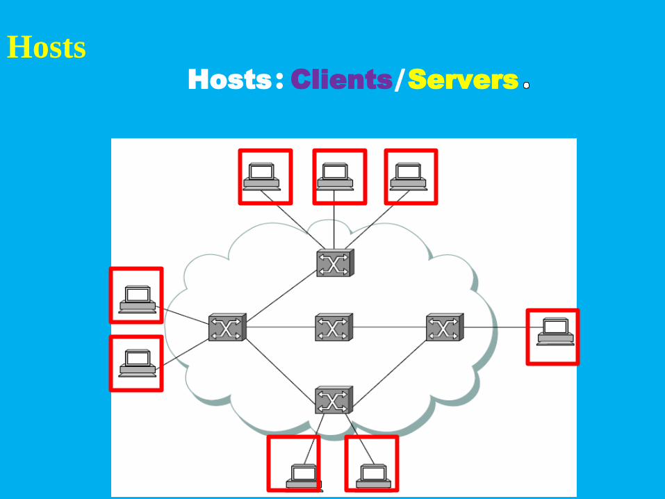
Hosts: Clients/ServersHosts

Host
Client or Server.
A client is a Computer, access a sever through
the Network.
A server is a Computer, usually, responds or
gives services to many clients.
A server usually is more powerful, in
processing and storage, than clients.
Network Core A part of a computer network which
interconnects networks, providing paths for
data communication between different LANs
or sub networks.
Main parts: Switches and Routers.
Each computer-based part in Edge or Core are
called a Node.

Core Nodes
Network Cores, Switches/Routers

Types of communication
Unicast: one node (address) at each end.
Multicast: one sending node; more than one
receiving nodes (addresses).
Broadcast: one sending node; to all nodes of a
sub-network

Types of communication
Multicast and Broadcast: one-way Communication
Multicast and Broadcast: need special core nodes

Time relation between sending and receiving
Simplex: Only one-way.
Half duplex: Sending and receiving in turn,
only one at a time .
Full duplex: Possible sending and receiving
simultaneously.
Hubs are Half duplex

Time relation between sending and receiving
Half duplex: one communication channel.
Full duplex: two communication channels, physical or logical.

Problem: high number of physical channels
If a network with n nodes is to use direct links,
it needs n(n-1)/2 links.
Solution: Switching, and/or Multiple Access.

Switching Networks
Three types:
Circuit switching.
Packet Switching.
Multiple access. ( sometimes the previous two
types are considered subset of this)

Circuit Switching
A physical channel is dedicated to one
communication throughout the communication.
Mostly used in non-data communication.
Inefficient in data communication, Data usually
has Burst nature

Circuit Switching

Packet Switching
Breaking the communication information down
into packets.
Destination address contained within each
packet, plus some other redundancies.
The same physical channel can be shared
among many nodes in a network.
Each packet can take a different route to its
destination (connectionless)
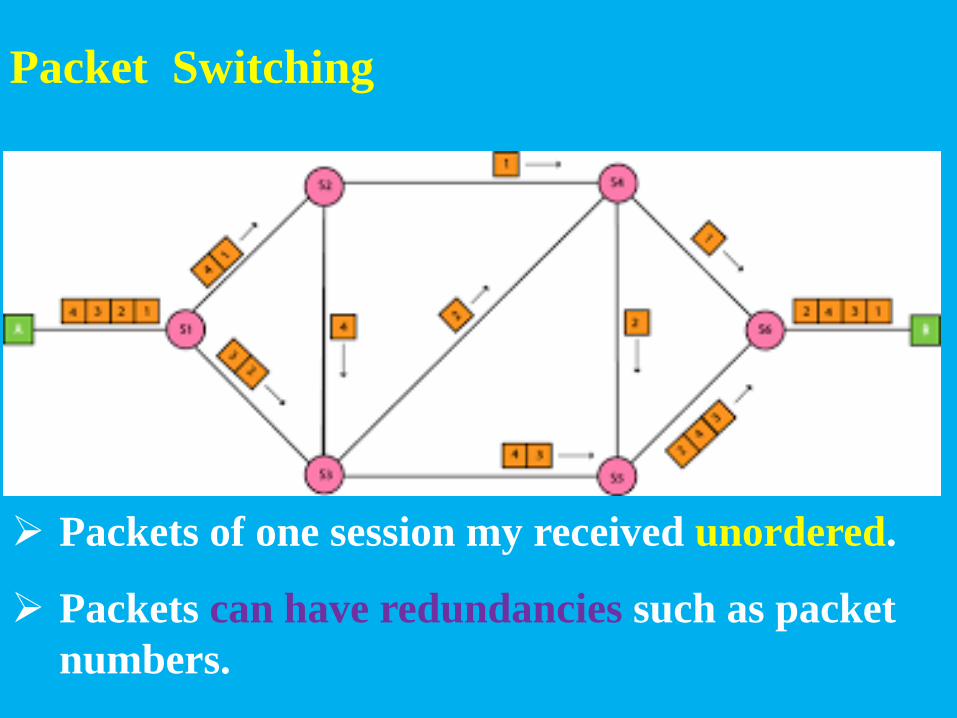
Packet Switching
Packets of one session my received unordered.
Packets can have redundancies such as packet
numbers.

Multiple Access
Techniques which are used to provide
communication service to multiple users over a
single channel simultaneously.

Multiple Access

Multiple Access Methods
● Frequency Division Multiple Access (FDMA)
● Time Division Multiple Access (TDMA)
● Wavelength Division Multiple Access (WDMA)
● Code Division Multiple Access (CDMA) / Spread Spectrum Multiple Access (SSMA)
● Packet Mode Multiple Access(Packet switching)

Multiple Access

Multiple Access in Networks
Packet Mode Multiple Access(Packet
switching).

Multiple Access in Networks
Packet switching when established between two
points, such as two routers, it is like TDMA
Multiplexing with random (stochastic) time
slots!

Multiple Access vs Multiplexing
There are similarities but:
Multiple access means many can access at one time,
one sends many receive but only one is desired
receiver (if unicast), such as Ethernet.
Multiplexing is a process to combine multiple signals
for transmitting it (the combined) over a single
channel or media. Generally multiplexing combines
several lower-speed signals for transmission over a
single higher-speed connection. One sends, different
data, one receives, different data. ADSL uses a type of
Multiplexing to separate data and voice.

Multiple Access vs Multiplexing
Multiplexing: There is no possibility that two
transmitted channel will damage each other’s
data.
Multiple access: if not just between two points,
there is always the possibility of collision
between the senders data.
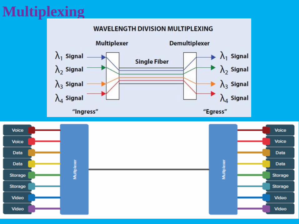
Multiplexing

Multiple Access & Switching
Circuit switching, FDMA, TDMA, CDMA may
be used for connection between networks,
especially when a media is shared between
computer networks and other networks(non-
data). They are not used in a computer
network.
ADSL uses a type of FDMA Multiplexing to
separate data and voice.

Layering in Computer Networks
Simplify communication.
Level abstraction in complicated
tasks(network programming).
Divide and Conquer in complex systems
(computer network).
Breaking up the sending messages into
separate components and activities. Each
component handles a different part of the
communication.

Layering in Computer Networks
Not unique definition.
The OSI 7 Layers model, more
theoretic.
The TCP/IP 5 Layers model, more
practical

OSI 7 Layers model

TCP/IP, 5 Layers model

OSI 7 Layers model vs TCP/IP, 5 Layers model
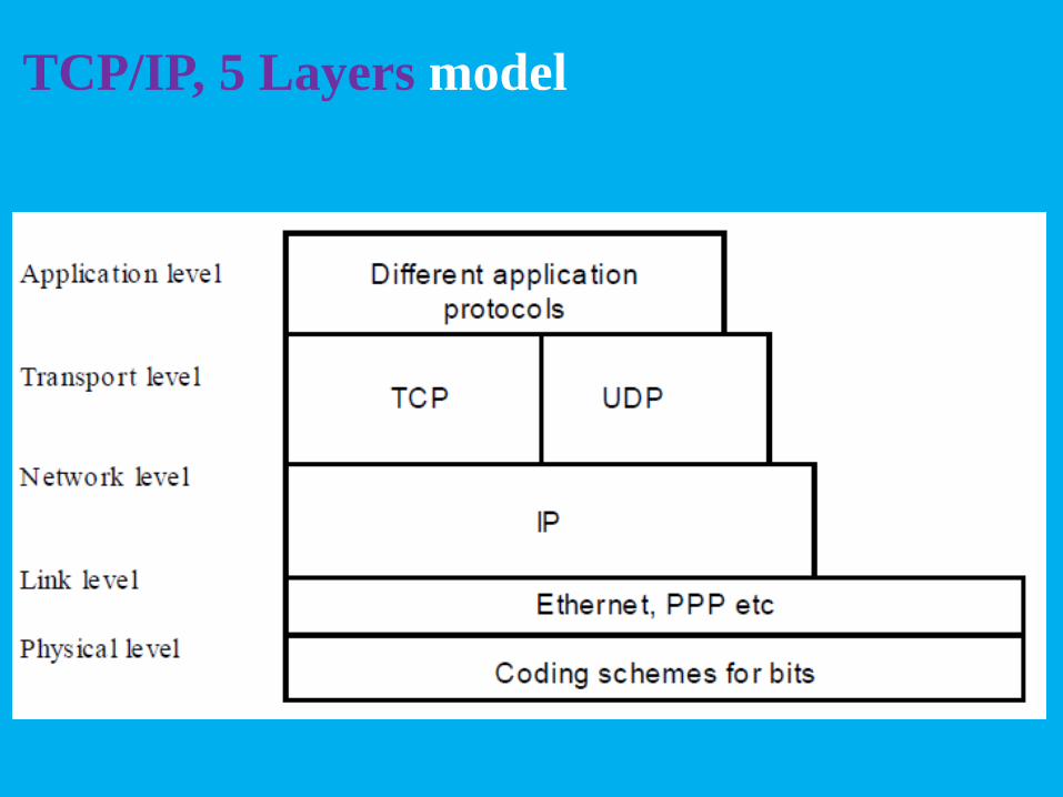
TCP/IP, 5 Layers model

Layers relation
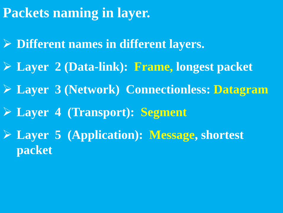
Packets naming in layer.
Different names in different layers.
Layer 2 (Data-link): Frame, longest packet
Layer 3 (Network) Connectionless: Datagram
Layer 4 (Transport): Segment
Layer 5 (Application): Message, shortest
packet

Packets size.
Transport layer: Maximum Segment size, MSS
MSS : Maximum Segment Size, in Bytes
Network layer: Maximum Datagram size, MTU
MTU : Maximum Transmission Unit, in Bytes
Data Link layer : Maximum Frame size, MTU

Layer protocols
A set of rules for communication within a
layer(two identical layers from sender and
receiver).
Protocols at one layer are unaware of issues at
another layer.
Protocol of physical layer is physical, such as:
transmission media(fiber, copper), signal
specification, Bandwidth.
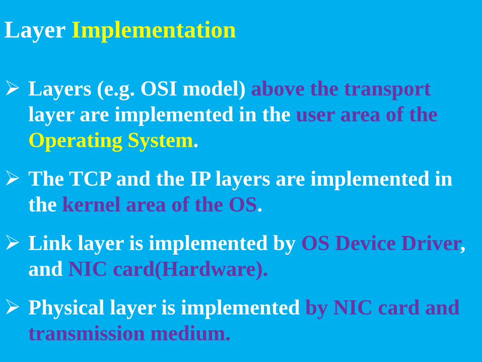
Layer Implementation
Layers (e.g. OSI model) above the transport
layer are implemented in the user area of the
Operating System.
The TCP and the IP layers are implemented in
the kernel area of the OS.
Link layer is implemented by OS Device Driver,
and NIC card(Hardware).
Physical layer is implemented by NIC card and
transmission medium.

Layer Implementation

Network categories
Based on distribution and size: WAN and LAN
In LANs, switches do routing in layer 2 (IEEE
802), or in layers 2 and 3 (IEEE 802/IP)
In WANs routers do routing in layer 3. routers
are very powerful and expensive.
In WANs for distance communication special
protocols for physical layer is needed, such as
channel coding, fiber channels, satellite channels,
WDM Multiplexing, …

Network categories A WAN, some routers, some LANs
A LAN can be as small as a router and a PC (a
core node and a host)

Internet? Internet with capital I.
Most important Computer Network.
A network with IP protocol in layer 3 and TCP
or UDP protocol in layer 4.
IP protocol is used in WANs and LANs

Local Area Network, LAN
Universal and pervasive: IEEE 802.x

IEEE 802.x
IEEE 802.x Layers

MAC Address
A 48-bit Address, such as D0-59-5C-03-8A-00
MAC Add. is unique (in World), for each NIC.
Most significant Bit: 0: Unicast, 1: Multicast; the
next bit: 0:External (LAN) Add., 1:Local
(LAN)Add.
FF-FF-FF-FF-FF-FF is Broadcast Add (in this LAN). Frames with this address are reached to every
NIC and received by that computer, on a given LAN.
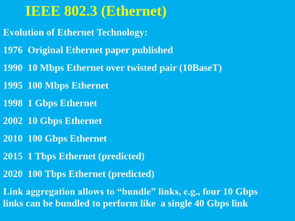
IEEE 802.3 (Ethernet)
Evolution of Ethernet Technology:
1976 Original Ethernet paper published
1990 10 Mbps Ethernet over twisted pair (10BaseT)
1995 100 Mbps Ethernet
1998 1 Gbps Ethernet
2002 10 Gbps Ethernet
2010 100 Gbps Ethernet
2015 1 Tbps Ethernet (predicted)
2020 100 Tbps Ethernet (predicted)
Link aggregation allows to “bundle” links, e.g., four 10 Gbps
links can be bundled to perform like a single 40 Gbps link

IEEE 802.3 (Ethernet)
Physical layer: Ethernet, medium: twisted wires
or fiber.
Switches have removed collisions.
Hubs (if used) possible of collision, IEEE 802.3 supports CSMA/CD.
Hubs communicate half-duplex and are used like
taps (only repeater not switch)

IEEE 802.3 (Ethernet)
Switches + star topology + full-duplex
No need to CSMA/CD
Problem: buffer (of switches) overflow. If the
Rate of packets sent for a node, from other
nodes, is more than the accepting rate of that node for a long time, results: buffer overflows.

Node distance in Ethernet
From a few meters to a few 100 meters.

Ethernet Frame structure
Maximum 1572 Bytes.
Last 4 Bytes are Checksum, for error detection.

IEEE 802.11(wireless LAN or Wi-Fi)
Commercial WLAN nodes supports at least, a,
b and g.
Some versions:

Multiple Access in Wi-Fi
Communication is Half-duplex
a, g and n use Orthogonal Frequency Division
Multiple Access (OFDM); b uses Direct
Sequence Spread Spectrum (DSSS)

Multiple Access in Wi-Fi, Spread Spectrum Techniques
Frequency Hopping Spread Spectrum
(FHSS).
Direct-Sequence Spread Spectrum
(DSSS)
Orthogonal Frequency-Division
Multiplexing (OFDM)

Multiple Access in Wi-Fi, FHSS The available frequency band is divided into smaller sub-bands,
f1, f2, …, fn.
The carrier frequency changes rapidly (hopping) among the
center frequencies of these sub-bands in a predetermined order.
In this example 3 channels defined, hopping time is 200 ms.

Multiple Access in Wi-Fi, FHSS The Pseudo random generator and the seed are the same for
Transmitter and Receiver.
Multiple access: with different frequency sequences.

Multiple Access in Wi-Fi, DSSS The data stream is combined via an XOR function with a high-
speed pseudo-random numerical sequence (PRN).
For 1 and 2 Mbps DSSS the PRN code is the 11-chip Barker
sequence, which is 10110111000.
The result is: 1: 01001000111 and 0: 10110111000

Multiple Access in Wi-Fi, DSSS
The code words have unique mathematical
properties that allow them to be correctly
distinguished from one another by a receiver
even in the presence of substantial noise and
interference.
Multiple access: with different codes.
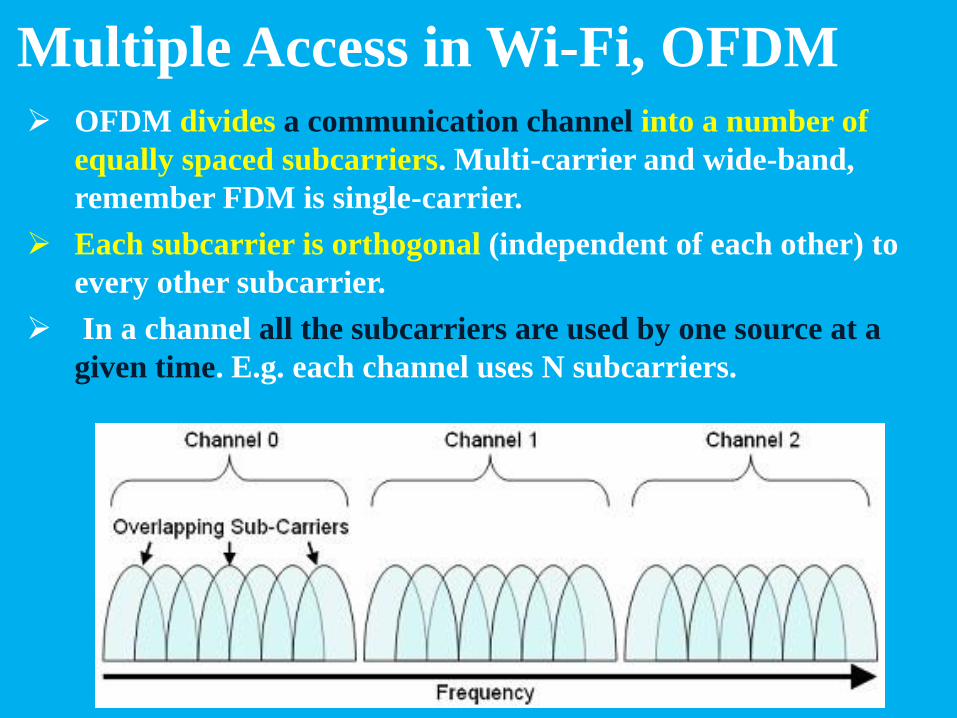
Multiple Access in Wi-Fi, OFDM OFDM divides a communication channel into a number of
equally spaced subcarriers. Multi-carrier and wide-band,
remember FDM is single-carrier.
Each subcarrier is orthogonal (independent of each other) to
every other subcarrier.
In a channel all the subcarriers are used by one source at a
given time. E.g. each channel uses N subcarriers.

Multiple Access in Wi-Fi, OFDM
Sources contend with one another at the data
link layer for access.
This is the reason why orthogonal subcarriers
are used in OFDM technology so that signals
going through different channels don’t interfere
with each other.
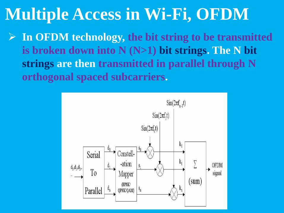
Multiple Access in Wi-Fi, OFDM
In OFDM technology, the bit string to be transmitted
is broken down into N (N>1) bit strings. The N bit
strings are then transmitted in parallel through N
orthogonal spaced subcarriers.
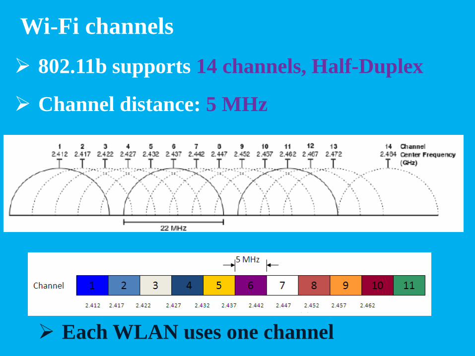
Wi-Fi channels
802.11b supports 14 channels, Half-Duplex
Channel distance: 5 MHz
Each WLAN uses one channel

Wi-Fi channels
In 802.11b channels overlap.
Best channels for adjacent WLANs are 1, 6 and 11,
otherwise increase of collisions and packet loss.

Wi-Fi channels
In 802.11a, just 8 channels without overlap. Each
WLAN, one channel Half-Duplex.

Wi-Fi problems
Problems: Hidden Nodes
and Exposed Nodes
Need resolutions.

Hidden Nodes
In an infrastructure WLAN, B is Access Point, host A and C
can not see (reach) each other, so A and C may start
communication with B, in a time.
A lot of collisions in B. Although some loss is acceptable but
it can result abnormal loss.

Exposed Node problem
In an infrastructure WLAN, A and D are Access
Points, host B sees A (not D) and C sees D (not A), B
and C are in range of each other. Each node can see
just its adjacent nodes
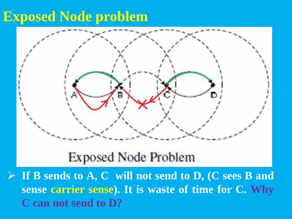
Exposed Node problem
If B sends to A, C will not send to D, (C sees B and
sense carrier sense). It is waste of time for C. Why
C can not send to D?

Resolution for Hidden Node and Exposed Node
Multiple Access with Collision Avoidance (MACA);
IEEE 802.11 RTS/CTS
A transmitting station sends a RTS frame to the
receiving station. The receiving station replies by
sending a CTS frame. On receipt of CTS frame, the
transmitting station begins transmission.
Any station hearing the RTS is close to the
transmitting station and remains silent long enough
for the CTS.
Any station hearing the CTS is close to the
receiving station and remains silent for a specified
time indicated in RTS/CTS frames.

Resolution for Hidden Node and Exposed Node
Multiple Access with Collision Avoidance (MACA);
IEEE 802.11 RTS/CTS
If C hears a CTS, without sending a RTS, it
understands that another host (here A) is sending
data to B and suspends transmission for a specified
time indicated in RTS/CTS frames.

Resolution for Hidden Node and Exposed Node
Multiple Access with Collision Avoidance (MACA);
IEEE 802.11 RTS/CTS
If C hears a RTS, but then doesn’t hear a CTS, it
understands that it is able to send data to D.

Resolution for Exposed Node
Multiple Access with Collision Avoidance (MACA);
IEEE 802.11 RTS/CTS
Directional antenna and WLAN sectorization also
can avoid exposed node problems.

WiFi frame format
Three types: Data, Control and Management.
The bits Type and subtype in Frame Control byte
determine the type of the frame.
Wi-Fi Modes of Operation
Two types:
Infrastructure
Ad-HOC or Peer to Peer
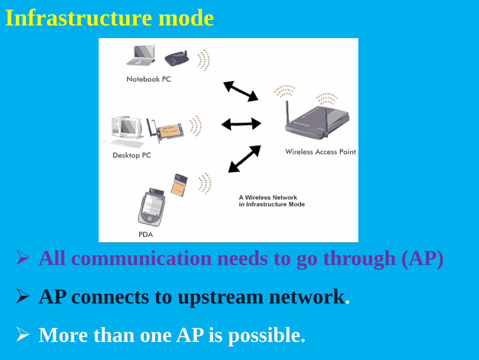
Infrastructure mode
All communication needs to go through (AP)
AP connects to upstream network.
More than one AP is possible.
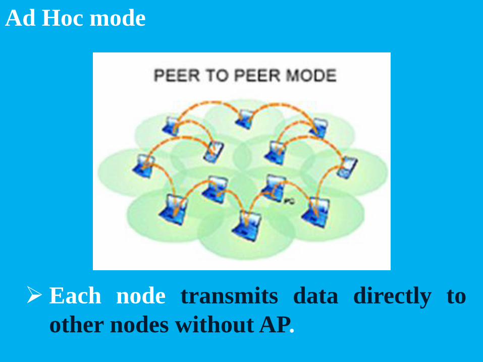
Ad Hoc mode
Each node transmits data directly to
other nodes without AP.

Infrastructure Security
Two modes: Secure and Open(without security)
Security Types: WEP(oldest), WPA, WPA2,
WPA3,
More complicate encryption , more secure.

Internetworking
Network of Networks
Connecting different networks by using
intermediary (core) devices such as routers devices.
Internetworking
Network of Networks
LANs, can, have different standards.
WANs protocols in layers 3, or 3 and 4.
The most important protocol: Internet

Internetworking
A network in layer3, or 3 and 4.
Networks Integration.
Internet
Full-Duplex
IP in layer 3.
UDP or TCP in layer 4.
IPv4, IPv6

Packet or Datagram in IPv4
IP is connectionless protocol (Complete
address on each packet; Datagram).
Each Datagram (packet) containing the
origin and destination Addresses.
The address is used to decide the next
hop at each routing point.

Packet or Datagram in IPv4
Length indicates the datagram length, max: 65535

Datagram Fragmentation and Reassembly in IPv4
Datagram must be fragmented to the new
datagrams equal to the smallest MTU of the
lower layer of the nodes (networks) it needs
to pass to reach to the destination.
In destination , the data in fields Ident, Flags
and Offset are used to Reassemble main
datagram.
Internet protocol mandates that all nodes
must support datagram with length 576,
otherwise they must fragment their frames.

Datagram Fragmentation and Reassembly in IPv6
Datagram are not fragmented in IPv6
Internet protocol mandates that all nodes
must support datagram with length 1280,
otherwise they must fragment their frames.

Addressing
IPv4; Address: 32 bits; possible add. = 232
= 4,294,967,296
IPv6; Address: 128 bits; possible add.= 2128

IPv4 Addressing
Two types: Classful and classless
Classful is becoming obsolete, and
replaced with classless.
Classful has three main classes and two
especial classes.

Classful(IPv4)
The first three bits determine the class.
Class D is for Multicast, class E is reserved.

Classful Addressing

Classful Addressing
Two parts: Network and Host
Network part is used by Routers.

Classful Addressing
Two parts: Network and Host
Class A can have to 128 Nets and 224 hosts.
Class C can have to 224 Nets and 128 hosts.

The network prefix identifies a network and the host number identifies a specific host (actually, interface on the network).
How do we know how long the network prefix is? – The network prefix is implicitly defined (see class-
based addressing)
– The network prefix is indicated by a netmask.
Network prefix and Host number
network prefix host number

Classful weakness
An address is dedicated to one user(router),
all hosts are reserved for this user. Waste of
the addresses.
Example: Address 144.144.x.x ( 144.144.0.0
to 144.144.255.255) can be routed to one
destination and can be sold to one user!
Internet growth cannot be supported.

Classless addressing and Subnetting
Replace classful addressing.
Finding Net Address (router Address) by use
of subnet Mask Address.

Basic Idea of Subnetting
Split the host number portion of an IP address into a subnet number and a (smaller) host number.
• Result is a 3-layer hierarchy
Then: • Subnets can be freely assigned within the organization
• Internally, subnets are treated as separate networks
• Subnet structure is not visible outside the organization
network prefix host number
subnet number network prefix host number
extended network prefix

Classless addressing and Subnetting
Bitwise AND ands one 32 Bits IP Address and a
subnet MASK; is used to find Network Address.
Network Address = IP Address AND Subnet Mask

Classless addressing and Subnetting
Host Address can be found from Net and IP addresses
Host Add. = IP Add. – Network Add.
144.16.72.57 – 144.16.64.0 = 0.0.8.57

192.168.5.130 /24 Subnet mask = 255.255.255.0
4 Subnets , 62 hosts/subnet Borrow 2 bits from host byte
Subnet A -> 192.168.5.1/26 to 192.168.5.62/26 Net ID : 192.168.5.62 & Subnet Mask = 192.168.5.0 Subnet B -> 192.168.5.65/26 to 192.168.5.126/26 Net ID : 192.168.5.126 & Subnet Mask = 192.168.5.64 Subnet C -> 192.168.5.129/26 to 192.168.5.190/26 Net ID: 192.168.5.190 & Subnet Mask = 192.168.5.128 Subnet D -> 192.168.5.193/26 to 192.168.5.254/26 Net ID: 192.168.5.254 & Subnet Mask = 192.168.5.192
192.168.5.0 = Net ID(routing)
Subnet Mask = 255.255.255.192 = /26

Classless InterDomain Routing
w.x.y.z/m
New routers use CIDR.
Makes the routing table smaller.
The same as using Subnet mask.
Addresses such as:
m or prefix shows the number of MSbs of Mask
which are 1, others are 0.
w.x.y.z is IP Address (Net Id must be extracted)

Classless InterDomain Routing
w.x.y.z/m
CIDR abandons the notion of classes.
Key Concept: The length of the network id (prefix,
m) in the IP addresses is kept arbitrary.
Consequence: Routers advertise the IP address and
the length of the prefix, m.

CIDR and Address assignments Backbone ISPs obtain large block of IP
addresses space and then reallocate portions of their address blocks to their customers.
Example: Assume that an ISP owns the address block 206.0.64.0/18,
which represents 16,384 (2(32-18)) IP addresses for sub-nets and hosts. Mask = 255.255.192.0
Suppose a client requires a sub-net with 800 host addresses.
CIDR: Assign a /22 block, e.g., 206.0.68.0/22, (one Address
From 206.0.64.0/22 to 206.0.124.0/22) 1 and allocate a block of 1,024 (210) IP addresses. e.g: 206D.0D.01000100b.0D to 206D.0D.01000111b.255D ; (1024-800 addresses are reserved for this client).
1. From 206D.0D.01000000b.0D to 206D.0D.01111100b.0D

Classless InterDomain Routing
CIDR: 32 M (225 ) Europe Addresses need only one input of routing table, 194.0.0.0/7 (In a router out
of Europe), 194=11000100; Mask = 254.0.0.0

Private IP Addresses
There are a few reserved IPv4 address spaces
which cannot be used on the internet.
These addresses cannot be routed on the
Internet, so packets containing these private
addresses are dropped by the Routers.
Private IP Addresses
These addresses are reserved as Private IP addresses.
These IPs can be used within a network, campus,
company and are private to it.
These IP addresses must be translated to some public
IP addresses using NAT process, or Web Proxy server
can be used.
Why Private Addresses:
• To overcome public(routable) IP Addresses shortage.
• It is more secure than the use of a public IP address,
private IP addresses are not directly visible on the
Internet (they are behind NAT).

IP Routing; Hop-by-Hop
The basis of today's IP networks.
Routing decisions are made at each router
independently and locally.
Algorithms of finding the shortest-paths
between nodes, such as the Dijkstra's
algorithm, can guarantee that no forwarding
loop exists in a network.
Each packet contains destination address.
Each router chooses next‐hop to destination.

IP Routing; Hop-by-Hop

IP Routing; Hop-by-Hop

Address Resolution Protocol, ARP
ARP is a procedure for mapping a dynamic IP address to a
permanent physical machine address (Media Access Control
or MAC) in a LAN.
Translate 32-bit addresses to 48-bit addresses and vice-
versa.
Translate layer 3 (IP Add.) Address to layer 2 (link layer, or
Ethernet) Address and vice-versa.
The ARP conversion table is updated every 15 minutes, (one
side Add. May change, e.g. Ethernet card in a host fails and
is replaced by a new one.
IPv6 uses the Neighbor Discovery Protocol, and its
extensions such as Secure Neighbor Discovery, rather than
ARP.

Transport Layer Protocols
The Layer 4(Transport) protocol.

Transport Layer Protocols, requirements
End-to-End: transmits the entire message
(Application layer packet) to the destination.
Therefore, it ensures the end-to-end delivery of an
entire message from a source to the destination.

Transport Layer Protocols, requirements
Give services to application layer messages.
Reliable delivery (connection oriented): provides
reliability message transfer by retransmitting the
lost and damaged packets.
Application discrimination, using port address.
Different application on end points. Working with
different application in a time.
Flow control: is used to prevent the sender from
overwhelming the receiver, or receiver overflow.

Transport layer protocols: TCP , UDP
Used in Internet. TCP/IP or TCP/UDP

Transport layer protocols: TCP , UDP
They provide Best-Effort network service, do not
provide any guarantee that data is delivered or that
delivery meets any Quality of Service (QoS).
Transport layer protocol: TCP
Connection oriented: Maintains state to provide reliable
service.
Byte-stream oriented: Handles byte streams instead of
messages
Full Duplex (needs response), inappropriate for Multicast and
Broadcast.
Flow control : Prevents sender from overrunning the receiver.
Congestion control: Prevents sender from overloading the
network (any node in the route). Uses feedback.
Uses handshake protocol like SYN, SYN-ACK, ACK .

TCP Frame
e.g. : source port, destination port and sequence
number.

Transport layer protocol: UDP
Connectionless: Does not maintains state, no reliable
service.
No response for a datagram, appropriate for
Multicast and Broadcast.
No Congestion control
No fixed order, all packets are independent of each
other.
UDP is faster ( error recovery is not attempted).
Just a single error checking mechanism (checksums).

UDP Frame
Just 8 bytes header.

Port Address or Port Number
A communication endpoint.
Used with TCP and UDP.
Provide a multiplexing service for multiple services or
multiple communication sessions at one network
address.
If clients, the port number is likely a temporary
number. If servers, the port number is likely a well-
known port number.

Some Well-Known Port numbers

Applications use proper layer 4 protocol

Performance Metrics
Macro-level
• Throughput
• Response time
• Availability
• Reliability
Micro-level
• Bandwidth
• Utilization
• Error rate
• Peak load
• Average load
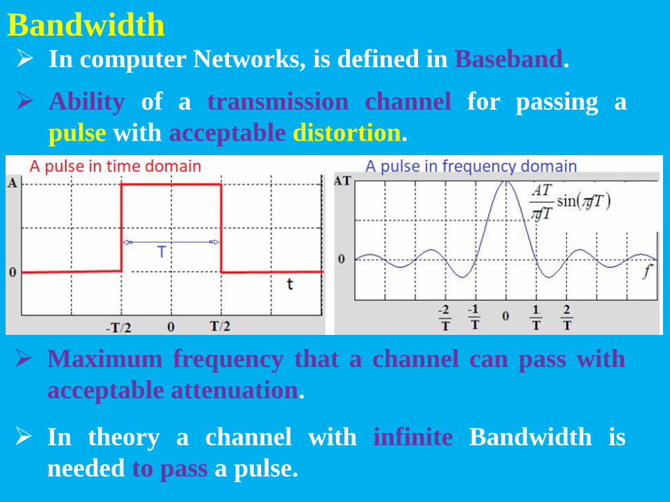
Bandwidth In computer Networks, is defined in Baseband.
Ability of a transmission channel for passing a
pulse with acceptable distortion.
Maximum frequency that a channel can pass with
acceptable attenuation.
In theory a channel with infinite Bandwidth is
needed to pass a pulse.

Bandwidth = B = (1/T) Hz
Bandwidth, practical
Black pulse is passed from a channel with
Bandwidth = (1/T) Hz, red is the input of the
channel or the output of an ideal channel.

Bit Rate (BR) and Baud Rate(fs)
Bit Rate(BR): The number of bits are transferred in
a network per unit of time, in bits per second (bps).
B >= BR / 2; Minimum Nyquist Bandwidth
Baud: One baud is one electronic state change per
second.
Baud Rate(fs ): or symbol rate or modulated rate,
The number of symbols are transferred in a
network per second, in Baud or symbols/s.
Each symbol is N bits, or N bits modulated with one
symbol.
fs = BR / N; fs < = 2*Bandwidth;
QPSK Modulation: N = 2, BR <= 2*2*Bandwidth
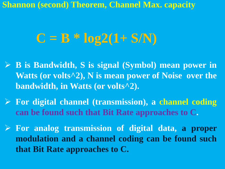
Shannon (second) Theorem, Channel Max. capacity
C = B * log2(1+ S/N)
B is Bandwidth, S is signal (Symbol) mean power in
Watts (or volts^2), N is mean power of Noise over the
bandwidth, in Watts (or volts^2).
For digital channel (transmission), a channel coding
can be found such that Bit Rate approaches to C.
For analog transmission of digital data, a proper
modulation and a channel coding can be found such
that Bit Rate approaches to C.

Latency
The time it takes for a packet, to travel from its point of origin
to the point of destination. The sum of:
Propagation delay: is a function of distance over speed with
which the signal propagates.
Transmission delay: is a function of the packet’s length and
data rate of the link.
Processing delay: Amount of time required to process the
packet header, check for bit-level errors, and determine the
packet’s destination.
Queuing delay: Amount of time the packet is waiting in the
queue until it can be processed.
It is defined one-way and include resending (if any) in reliable
communication.
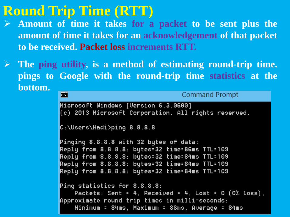
Round Trip Time (RTT) Amount of time it takes for a packet to be sent plus the
amount of time it takes for an acknowledgement of that packet
to be received. Packet loss increments RTT.
The ping utility, is a method of estimating round-trip time.
pings to Google with the round-trip time statistics at the
bottom.

Jitter
Variation in RTT.

Throughput
𝑻𝒉𝒓𝒐𝒖𝒈𝒉𝒑𝒖𝒕 =𝑵𝒆𝒕𝑴𝒆𝒔𝒔𝒂𝒈𝒆𝑷𝒂𝒄𝒌𝒆𝒕𝑺𝒊𝒛𝒆
𝑴𝒆𝒔𝒔𝒂𝒈𝒆 𝑷𝒂𝒄𝒌𝒆𝒕𝑺𝒊𝒛𝒆
𝑴𝒆𝒔𝒔𝒂𝒈𝒆𝑷𝒂𝒄𝒌𝒆𝒕𝑺𝒊𝒛𝒆
𝑻𝒓𝒂𝒏𝒔𝒇𝒆𝒓𝑻𝒊𝒎𝒆
𝑻𝒉𝒓𝒐𝒖𝒈𝒉𝒑𝒖𝒕 =𝑵𝒆𝒕𝑴𝒆𝒔𝒔𝒂𝒈𝒆𝑷𝒂𝒄𝒌𝒆𝒕𝑺𝒊𝒛𝒆
𝑻𝒓𝒂𝒏𝒔𝒇𝒆𝒓𝑻𝒊𝒎𝒆
NetMessagePacketSize = The length of end-to-end packet
without redundancies.
MessagePacketSize= The length of whole end-to-end packet.
TransferTime= RTT + message packet duration.
Packet loss and redundancies in packets, increase RTT and
reduce Throughput.