advanced ptz keyboard controller - flir · advanced ptz keyboard controller acckbd150. thank you...
TRANSCRIPT

Copyright © 2009 Digimerge Technology Inc.
www.digimerge.com
Right For Business™
INSTRUCTION MANUALEnglish Version 1.0
ADVANCED PTZ KEYBOARD CONTROLLER
ACCKBD150

Thank you for purchasing this product. Digimerge is committed to providing our customers with a high quality, reliable security solution.This manual refers to the following models:
• ACCKBD150
For more information on this product, firmware updates, and accessory products, please visit us at:
www.digimerge.com
CAUTION
RISK OF ELECTRIC SHOCKDO NOT OPEN
CAUTION: TO REDUCE THE RICK OF ELECTRIC SHOCK DO NOT REMOVE COVER. NO USER SERVICABLE PARTS INSIDE.
REFER SERVICING TO QUALIFIED SERVICE PERSONNEL.
The lightning flash with arrowhead symbol, within an equilateral triangle, is intended to alert the user to the presence of uninsulated "dangerous voltage" within the products ' enclosure that may be of sufficient magnitude to constitute a risk of electric shockThe exclamation point within an equilateral triangle is intended to alert the user to the presence of important operating and maintenance (servicing) instructions in the literature accompanying the appliance.
WARNING: TO PREVENT FIRE OR SHOCK HAZARD, DO NOT EXPOSE THIS UNIT TO RAIN OR MOISTURE.
CAUTION: TO PREVENT ELECTRIC SHOCK, MATCH WIDE BLADE OF THE PLUG TO THE WIDE SLOT AND FULLY INSERT.

FCC COMPLIANCE STATEMENT
FCC INFORMATION: THIS EQUIPMENT HAS BEEN TESTED AND FOUND TO COMPLY WITH
THE LIMITS FOR A CLASS A DIGITAL DEVICE, PURSUANT TO PART 15 OF THE FCC RULES.
THESE LIMITS ARE DESIGNED TO PROVIDE REASONABLE PROTECTION AGAINST
HARMFUL INTERFERENCE WHEN THE EQUIPMENT IS OPERATED IN A COMMERCIAL
ENVIRONMENT. THIS EQUIPMENT GENERATES, USES, AND CAN RADIATE RADIO
FREQUENCY ENERGY AND IF NOT INSTALLED AND USED IN ACCORDANCE WITH THE
INSTRUCTION MANUAL, MAY CAUSE HARMFUL INTERFERENCE TO RADIO
COMMUNICATIONS. OPERATION OF THIS EQUIPMENT IN A RESIDENTIAL AREA IS LIKELY
TO CAUSE HARMFUL INTERFERENCE IN WHICH CASE THE USER WILL BE REQUIRED TO
CORRECT THE INTERFERENCE AT HIS OWN EXPENSE.
CAUTION: CHANGES OR MODIFICATIONS NOT EXPRESSLY APPROVED BY THE PARTY
RESPONSIBLE FOR COMPLIANCE COULD VOID THE USER'S AUTHORITY TO OPERATE
THE EQUIPMENT.
THIS CLASS A DIGITAL APPARATUS COMPLIES WITH CANADIAN ICES-003.
CET APPAREIL NUMÉRIQUE DE LA CLASSE A EST CONFORME À LA NORME NMB-003 DU
CANADA.
CE COMPLIANCE STATEMENT
WARNING
THIS IS A CLASS A PRODUCT. IN A DOMESTIC ENVIRONMENT THIS PRODUCT MAY CAUSE
RADIO INTERFERENCE IN WHICH CASE THE USER MAY BE REQUIRED TO TAKE
ADEQUATE MEASURES.
i

ii
IMPORTANT SAFEGUARDS
1. Read these instructions. 2. Keep these instructions. 3. Heed all warnings. 4. Follow all instructions. 5. Do not use this apparatus near water. 6. Clean only with dry cloth. 7. Do not block any ventilation openings. Install in accordance with the
manufacturer's instructions. 8. Do not install near any heat sources such as radiators, heat registers, stoves, or other apparatus (including amplifiers) that product heat. 9. Do not defeat the safety purpose of the polarized or grounding-type
plug. A polarized plug has two blades with one wider than the other. A grounding type plug has two blades and a third grounding prong. The wide blade or the third prong is provided for your safety. If the provided plug does not fit into your outlet, consult an electrician for replacement of the obsolete outlet.
10. Protect the power cord from being walked on or pinched particularly at plugs, convenience receptacles, and the point where they exit from the apparatus.
11. Only use attachments/accessories specified by the manufacturer. 12. Unplug this apparatus during lightning storms or when unused for long periods of time. 13. Refer all servicing to qualified service personnel. Servicing is required
when the apparatus has been damaged in any way, such as power-supply cord or plug is damaged, liquid has been spilled or objects have fallen into the apparatus, the apparatus has been exposed to rain or moisture, does not operate normally, or has been dropped.
14. CAUTION - THESE SERVICING INSTRUCTIONS ARE FOR USE BY QUALIFIED SERVICE PERSONNEL ONLY. TO REDUCE THE RISK OF ELECTRIC SHOCK DO NOT PERFORM ANY SERVICING OTHER THAN THAT CONTAINED IN THE OPERATING INSTRUCTIONS UNLESS YOU ARE QUALIFIED TO DO SO.
15. Use Certified/Listed Class 2 power supply transformer only.
iii
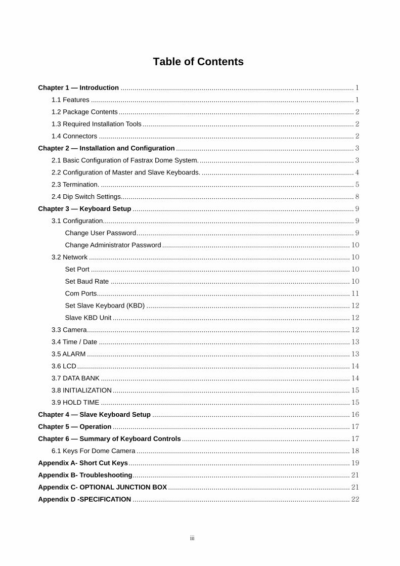
Table of Contents
Chapter 1 — Introduction ...................................................................................................................... 1
1.1 Features ..................................................................................................................................... 1
1.2 Package Contents ....................................................................................................................... 2
1.3 Required Installation Tools ........................................................................................................... 2
1.4 Connectors ................................................................................................................................. 2
Chapter 2 — Installation and Configuration .......................................................................................... 3
2.1 Basic Configuration of Fastrax Dome System. .............................................................................. 3
2.2 Configuration of Master and Slave Keyboards. ............................................................................. 4
2.3 Termination. ................................................................................................................................ 5
2.4 Dip Switch Settings...................................................................................................................... 8
Chapter 3 — Keyboard Setup ................................................................................................................ 9
3.1 Configuration............................................................................................................................... 9
Change User Password.............................................................................................................. 9
Change Administrator Password ............................................................................................... 10
3.2 Network .................................................................................................................................... 10
Set Port ................................................................................................................................... 10
Set Baud Rate ......................................................................................................................... 10
Com Ports................................................................................................................................ 11
Set Slave Keyboard (KBD) ....................................................................................................... 12
Slave KBD Unit ........................................................................................................................ 12
3.3 Camera..................................................................................................................................... 12
3.4 Time / Date ............................................................................................................................... 13
3.5 ALARM ..................................................................................................................................... 13
3.6 LCD .......................................................................................................................................... 14
3.7 DATA BANK .............................................................................................................................. 14
3.8 INITIALIZATION ........................................................................................................................ 15
3.9 HOLD TIME .............................................................................................................................. 15
Chapter 4 — Slave Keyboard Setup .................................................................................................... 16
Chapter 5 — Operation ........................................................................................................................ 17
Chapter 6 — Summary of Keyboard Controls ..................................................................................... 17
6.1 Keys For Dome Camera ............................................................................................................ 18
Appendix A- Short Cut Keys ................................................................................................................ 19
Appendix B- Troubleshooting.............................................................................................................. 21
Appendix C- OPTIONAL JUNCTION BOX ............................................................................................ 21
Appendix D -SPECIFICATION .............................................................................................................. 22

Chapter 1 — Introduction
1.1 Features This keyboard controller is capable of controlling dome cameras.
Variable speed control joystick with zoom controlling handle.
Program and recall programmed preset positions, auto scan, tour, pattern, from the selected dome camera.
Two levels of password are supported for higher security, administrator and user.
Up to 254 dome cameras controllable including 64 dome cameras with Alarm mode.
Up to 3 slave of the same type keyboard controllers can be connected to the master keyboard.
Battery backed-up clock displays real time on the LCD screen.
Up to two dome cameras’ programmed data can be downloaded to nonvolatile memory space, and later uploaded to the new dome camera.
The dome with the ID up to 3999 can be controlled.
Scan range option: 32, 254, 3999.
Figure 1 – Typical system Configuration
1

1.2 Package Contents
The package contains the following.
Description Quantity
Keyboard controller 1
Instruction manual 1
12VDC Power supply (SMPS) 1
Power Cord 1
1.3 Required Installation Tools
No special tools are required to install the KBD controller. Refer to the installation manuals for the other
items that make up part of your system.
1.4 Connectors
CONNECTOR USAGE
RS232 RS232:UPGRADE
DOME2 RS485:DOME/SLAVE KEYBOARD
DOME1 RS485:DOME
DATA2 FOR JUNCTION BOX ONLY
DATA1 FOR JUNCTION BOX ONLY
DC12V FOR POWER SUPPLY
NOTE: DON’T CONNECT THE DATA1 PORT AND DC12V PORT TOGETHER.
2
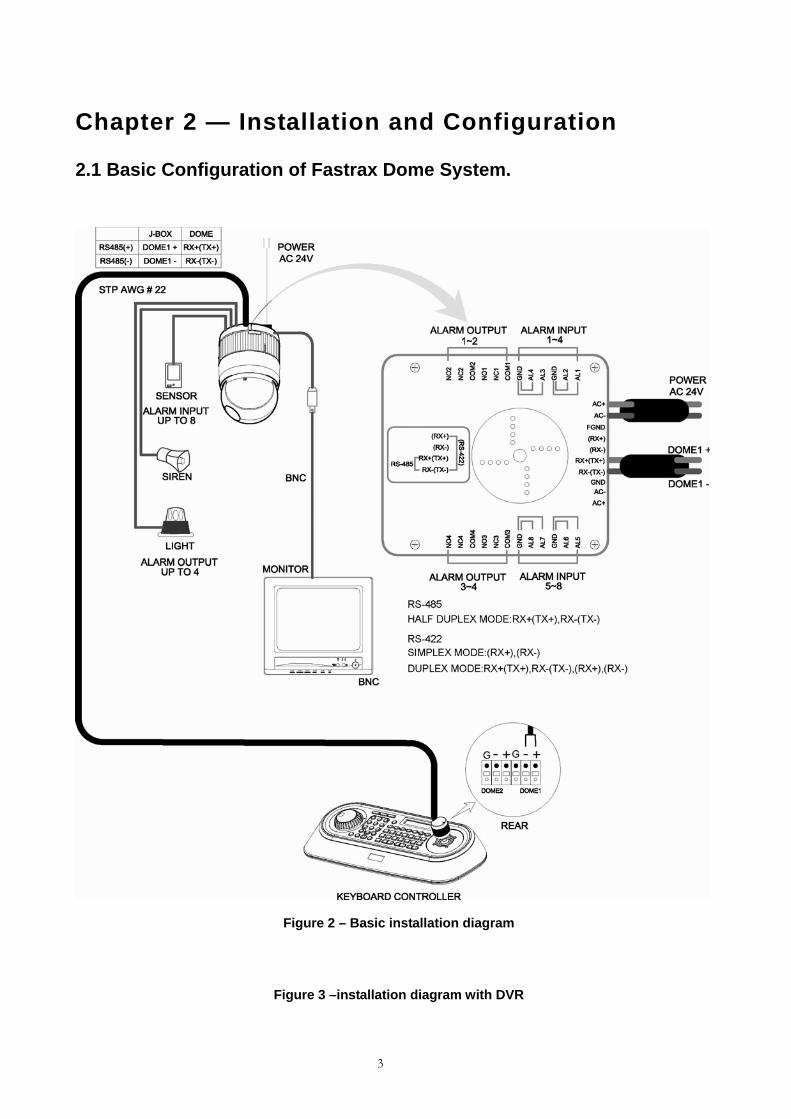
Chapter 2 — Installation and Configuration
2.1 Basic Configuration of Fastrax Dome System.
Figure 2 – Basic installation diagram
Figure 3 –installation diagram with DVR
3

2.2 Configuration of Master and Slave Keyboards.
Figure 3 –Master and Slave keyboard connection
Note: Connect the DOME1 port of all slave keyboards to the DOME2 port of the master keyboard
and set the DIP SW 1 and 2 as the figure above.
4

Without J-BOX
Master Keyboard Setting Slave Keyboard Setting
1. 1. Dip switch the of S1 is "ON"
2.
th8
2.
3.
4.
5

With J-BOX
Master Keyboard Setting Slave Keyboard Setting
1.
1. Dip switch the of S1 is "ON"
2.
th8
6
2.
3.
4.
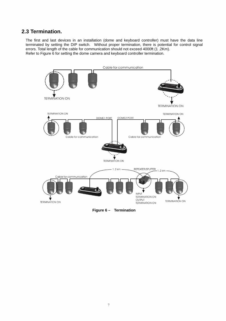
2.3 Termination. The first and last devices in an installation (dome and keyboard controller) must have the data line terminated by setting the DIP switch. Without proper termination, there is potential for control signal errors. Total length of the cable for communication should not exceed 4000ft (1 .2Km). Refer to Figure 6 for setting the dome camera and keyboard controller termination.
Figure 6 – Termination
7

2.4 Dip Switch Settings.
Termination and Master/Slave: Set the switches according to your configuration.
ON
9JS1 1 2 3 4 5 6 7 8
Figure 7 – Keyboard DIP Switches
NO SETTING DESCRIPTION ON 1 OFF DOME1 Termination
ON 2 OFF DOME2 Termination
ON 3 OFF J-BOX Data2 Termination
4~6 OFF Reserved ON DOWNLOAD ON 7 OFF DOWNLOAD OFF ON SLAVE
8 OFF MASTER
Table 1 - S1 Switch Setting
8

Chapter 3 — Keyboard Setup To setup the keyboard controllers, the user needs to setup the network, passwords and perform special tasks such as Uploading and Downloading programmed data from the dome cameras. To enter the Keyboard menu, press and hold CTRL and press MENU expressed as CTRL+MENU in the manual. You will see the following menu.
MAIN MENU
1.Configuration
2.Network
3.camera
4.Time/Date
5.Alarm
6.LCD
7.Data Bank
8.Initialization
9.Hold time:005s
Save and Exit
MAIN MENU
1.Configuration
To scroll menu items, move the joystick up or down.
To enter the sub menu, push the joystick to the right.
To change the value, twist the joystick handle.
3.1 Configuration
1. Key beep:ON ON: the KBD controller’s internal speaker will sound when you press key.
2. key-lock:OFF OFF - Disable Auto Key-Lock function. 15Min, 30Min, 60Min - After elapsed setup time, keyboard locks automatically. User needs the login password to operate the Keyboard again
3. S-Range:32 Scan Range: 32, 254, 3999 –scan dome cameras up to setting number.
4. Chg User PW Enters the change user password submenu.
5. Chg Admin PW Enters the change administrator password submenu.
6. Rescan dome Rescan the connected dome cameras.
Save and exit Save the changed settings and return to the previous menu
Change User Password Current PW : XXXX
NEW PW : YYYY Confirm PW : YYYY Save and Exit
This screen allows you to change user password.
Enter 4 digits password and press ENTER . Factory Default setting is 1111.
The user is not allowed to setup or program the KBD controller and the Dome Camera.
9

Change Administrator Password Current PW : XXXX NEW PW : YYYY Confirm PW : YYYY Save and Exit
This screen allows you to change administrator password.
Enter 4 digits password and press ENTER . Factory Default setting is 9999.
Note) Factory default Administrator’s password is 9 9 9 9 + ENTR . User password is 1 1 1 1 + ENTR If you forgot your own password, contact service personnel or distributor.
3.2 Network
1. J-BOX Set: OFF Select to use the optional Junction Box or not.
2. Set Port Select the baud rate and the connected unit’s protocol.
3. MUX Config Not supported.
4. Set Slave KBD Select to use the slave keyboard or not.
Save and exit Save the changed settings and return to the previous menu Set Port 1.Set Baud Rate
2.Com Ports
Exit(ESC)
Set Baud Rate Enters the Baud Rate setup submenu.
Com Ports Enters the Communications Ports setup submenu.
Exit Return to the previous menu.
Set Baud Rate
10
Set Baud Rate
1.DOME1 : 9600
2.DOME2 : 9600
3.RS232 : 9600
Save and Exit
Set Baud Rate
1.DOME1 : 9600
2.D2/DVR : 9600
3.ALARMPC : 9600
4.MUX/KBD : 9600
5.DVR/AUX : 9600
Save and Exit
< J-BOX :OFF> < J-BOX :ON>

Com Ports
Com Ports
1.DOME1 : DOME
2.DOME2 : NONE
3.RS232 : NONE
Save and Exit
Com Ports
1.DOME1 : DOME
2.D2/DVR : NONE
3.ALARMPC: NONE
4.MUX/KBD: NONE
5.DVR/AUX: NONE
Save and Exit
< J-BOX :OFF> < J-BOX :ON>
J-BOX :OFF
DOME1 2400~38400 None/Dome
DOME2 2400~38400 None/Dome/KBDDUP/KBDTRI/AUX IN
RS232 2400~38400 None/AUX IN
J-BOX :ON
DOME1 2400~38400 RS485 :None/Dome
D2/DVR 2400~38400 RS485 :None/Dome/AUX IN
ALARMPC 2400~38400 RS232 :None/AUX IN
MUX/KBD 2400~38400 RS485 :None/AUX IN
DVR/AUX 2400~38400 RS232 :None/AUX IN
AUX IN : outputs the auxiliary signal input to Dome1(FASTRAX,PELCO only)
Note: JBOX is an optional device that is not included with the KBD.
JBOX menu has to be set to OFF in the menu if you do not have this optional JBOX.
11

Set Slave Keyboard (KBD) Set Slave Kbd 1.Slave KBD : OFF
2.MUX cont : OFF
3.DVR cont : OFF
4.Dome Menu : OFF
5.Slave KBD Unit
Save and Exit
Note: MUX and DVR control are not supported.
This screen allows you set up Slave KBD controller.
1. Slave KBD ON: Slave KBD controller can control the unit which is connected Master KBD controller.
4. Dome Menu ON: Slave KBD controller is allowed to access Dome menu setup.
5. Slave KBD Unit Enters the Slave keyboard unit submenu.
Save and exit Save the changed settings and return to the previous menu
Slave KBD Unit 1.Slave ID1 : OFF
2.Slave ID2 : OFF
3.Slave ID3 : OFF
Save and Exit
Slave KBD Unit
This setup allows you set up the slave keyboard, how many slave keyboards. To use the slave keyboard, set ON.
3.3 Camera Cam<- PR PT BR
0001 F2E D1 9600
Cam : Camera ID PR : Protocol[F2,F2E,P-D(PELCO-D),P-P(PELCO-P)] PT : Port[D1(DOME1),D2(DOME2)] BR : Baud rate
This camera setup is listed up to 64 cameras and the camera ID has up to 3999. When the keyboard has that the Alarm Check option is ON, the camera setup is set automatically after the keyboard checks the camera at the first power on or after the scan dome function.
12

At this time, the F2E protocol could not be changed. To add the other camera: 1. Select the blank line (- - -) by moving the joystick down or up. 2. Twist the handle of the joystick clockwise, then the next camera number displays or press camera
number and CAM key, if that number is not already defined, the camera number displays. 3. Set the appropriate protocol and port moving the cursor (←)by the joystick.
Alarm check option is ON: P-D (PELCO-D), P-P (PELCO-P) Alarm check option is OFF: F2, F2E, P-D (PELCO-D), P-P (PELCO-P)
4. Set the appropriate baud rate of the camera. 5. Repeat step 1-4 to add a new camera. 6. Press CTRL to save and exit. 7. To change the camera, repeat step 2-6 after selecting the desired camera number. Press OFF to delete the saved camera. Press the ESC key to exit without saving. Note) The baud rate of the F2E is according to the value of the set baud rate menu. When the keyboard has that the alarm check option is OFF, the camera setup displays the blank value after the first power on. At this time, set all cameras according to the procedure above.
3.4 Time / Date
TIME/DATE
1.Dispaly :ON
2.Year :2007
3.Month :JUL
4.Day :02 MON
5.Hour :12
6.Minute :20
Save and Exit
Set the KBD controllers’ Time & Date 3.5 ALARM
Alarm
1.Check :ON
2.Beep :ON
Save and Exit
1. Alarm Check When set to ON, the KBD controller will check alarm signal and each port can be connected 32 dome cameras. When set to OFF, it will not check alarm signal and each port can be connected 128 dome cameras.
2. Alarm Beep When set to ON, the KBD controller will sound beep when alarm signal is detected.
Save and exit Save the changed settings and return to the previous menu
NOTE: When domes are installed more than 64 at one dome port, you should set the alarm
check to OFF.
13

3.6 LCD LCD
1.Bright :03
2.Backlight :ON
Save and Exit
- Bright : 01~12 - Backlight : ON/OFF
Data Bank
1:Download->
2:Download->
Exit(ESC)
3.7 DATA BANK The data bank function allows you to download the programmed data from the selected camera and to upload the saved data of the keyboard to the selected camera. Push the joystick to the right to download.
Data Bank 1
065.5%
After downloading, if success, press ENTER. Data Bank 1
Download OK
After downloading, if fail, press ENTER. Data Bank 1
Download Error
After downloading, it displays as the right figure. Data Bank
1: 0001E
2: Download->
Data Bank 1
Upload
Clear Data
Exit(ESC)
To upload, select the upload and push the joystick to the right. To clear the saved data, select the clear data and push the joystick to the right.
14

3.8 INITIALIZATION MAIN MENU
8.Initialization To initialize the keyboard, select Initialization. After Initialization, the keyboard returns it to the factory value.
ARE YOU SURE?
ENTER OR ESC
3.9 HOLD TIME
MAIN MENU
9.Hold time:005s When the dome ID of the master keyboard is the same as the slave keyboard or the one from AUX IN mode(dome2 port), during the hold time after the master keyboard control the dome, the slave keyboard and the unit from the AUX IN mode(dome2 port) cannot control the dome.
INF (Infinite) Slave Keyboard user never has the right to control the dome which is selected by master Keyboard users.
1 ~ 200 second After select hold time, the slave keyboard can control the dome.
When the dome ID of the master keyboard is not the same as the slave keyboard or the one from AUX IN mode (dome2 port), the hold time has no relation.
15

Chapter 4 — Slave Keyboard Setup Master keyboard should be setup as following procedure. 1. Check for dip switch the 8th of S1 “OFF”. 2. Press CTRL + MENU. Check Slave KBD setting “ON”. Network � Set Slave KBD � Slave KBD : ON Network � Set Slave KBD � Slave KBD Unit: ON for the desired slave keyboard Slave keyboard need to be setup with the following procedure. 1. Check for dip switch the 8th of S1 is “ON”. 2. If you setup all connection correctly and turn on slave keyboard, you should see following screen.
Ver x.x Slave1
Password : xxxx
←Current Device ID = 1
←Default setting is 9 9 9 9 for administrator, 1 1 1 1 for user
Not connected
←means that the controller is not connected to master keyboard
3. Press CTRL + MENU. Set the Slave ID to 01
16
MAIN MENU
1.Configuration
2.Network
3.LCD
4.Initialization
Exit(ESC)
Configuration
1.Key Beep : ON
2.key Lock : OFF
3.Chg User PW
4.Chg Admin PW
Save and Exit
LCD
1.Bright :03
2.Backlight :ON
Save and Exit
Network
1.J-BOX Set : OFF
2.Keyboard ID : 01
3.BPS:9600
Save and Exit

Chapter 5 — Operation
5.1 Keyboard Lock/Unlock (Hidden command) When the user leaves the control desk, he may wish to lock the keyboard controller to prevent unauthorized use. Pressing 7 7 7 + ENTER will lock the keyboard controller. Pressing 7 7 7 + ENTER while the keyboard is locked will open the password screen. If the correct password is entered, the keyboard controller will return to normal operation. If the power is turned OFF and ON while the keyboard is locked, it will ask for the password. Entering the correct password will cause the keyboard controller to return to normal operation. NOTE : If you forget your own passwords, turn off the keyboard controller, contact your distributor to get a 4-digit back door password. This will change the passwords to the factory default. Contact your distributor to get the 4-digit back door password.
Chapter 6 - Summary of Keyboard Controls
Key operation example CTRL + MENU : Press and hold down CTRL Key and press MENU Key.
1 + CAM : Press 1 Key, CAM Key sequentially.
CTRL + JOYSTICK : Press and hold down CTRL Key while manipulate Joystick Handle.
ENTER + JOYSTICK : Press and hold down ENTER Key while manipulate Joystick Handle.
17

6.1 Keys for Dome camera
Function Key Label Descriptions
Camera Selection No. +
Displays the selected camera and allows the camera to be controlled by the keyboard controller, if the selected camera is a dome camera. Function number selection with function keys. (e.g., 1 + CAM, 3 + TOUR, 5 + SCAN, 6 + PRST)
Cancel
Cancels current inputs. Exits from currently running functions or menu, error status, etc.
Alarm
Disregards all currently activated alarms and turns off the beep temporarily. If alarm is activated again within the programmed hold time, the timer will restart and beep again.
Relay ON
Relay No. 1~4 + ON will activate the selected relay.
Relay OFF
Relay No. 1~4 + OFF will disable the selected relay.
Home
Immediately calls Home function. Deletes selected value or function in programming mode
Global
Sends all cameras to preset (e.g., 1, 2… 5 5 + ENTER). 8 8 8 + ENTER: Night shot mode, 9 9 9 + ENTER: Normal mode
Call Preset position
Pressing Prst will bring up the preset programming menu. Recalls preset;( e.g.; 1 , 2 … 3 1 … 2 4 0 + PRST ) In the preset or tour programming mode, the operator can review the exiting preset (selected by cursor) by pressing this key.
Tour
Pressing TOUR will bring up the tour programming menu directly Recalls programmed presets or functions sequentially. (e.g., 1 + TOUR)
Pattern
Pressing PTRN will bring up the pattern programming menu directly. Repeats the selected pattern of the current dome camera. (e.g., 1 + PTRN)
Auto Scan
Pressing Scan will bring up the Auto Scan programming menu. Calls Auto panning function (e.g., 2 + SCAN repeats Auto Scan 2).
Configuration
Enters programming menu. CTRL+MENU will invoke Keyboard set up menu
Program
No. + CTRL + PRST will store current view as a preset directly. No. + CTRL + TOUR will open programming menu No. + CTRL + SCAN will open programming menu
Control
CTRL+Joystick : In a programming mode (Preset, Pattern, Scan, Privacy….) the joystick operates as if in the normal control mode. While pressing and holding down the CTRL key, all movements of the joystick will start recording when in the pattern programming menu. CTRL+Joystick:, In normal operation mode, manual speed of the joystick control will be operated in turbo mode.
Enter
Completes entering data for the password or title.
Manual Focus Overrides auto focus. Moving the Zoom handle reactivates Auto Focus mode.
Manual Iris Overrides auto iris. Moving the joystick reactivates Auto Iris mode.
Zoom Zoom control.
Joystick Twist ,Up / Down Left / Right
Zoom control (proportional to position) Tilt control, Cursor Up / Down in the menu Pan control, Cursor Left / Right or Page scroll in the Menu.
18

19
Appendix A- Short Cut Keys
Short Cut Key Function
PRST Pop up preset setup menu.
TOUR Pop up Tour setup menu.
PTRN Pop up Pattern setup menu.
SCAN Pop up Auto Scan setup menu.
NO.+PGM +PRST Store the current view at the selected number.
Short Cut Key Function Short Cut Key Function
1 + ON Turn On Relay 1. 1 + OFF Turn Off Relay.
2 + ON Turn On Relay 2. 2 + OFF Turn Off Relay.
3 + ON Turn On Relay 3. 3 + OFF Turn Off Relay.
4 + ON Turn On Relay 4. 4 + OFF Turn Off Relay.
7 + ON Change FOCUS to AUTO 7 + OFF Change FOCUS
to manual
8 + ON Change AE to AUTO 8 + OFF Change AE to manual
9 + ON Change Night Shot to AUTO
10 + ON Night Shot on (go to the manual
mode) 10 + OFF
Night Shot off (go to the
manual mode)
11 + ON BLC on (AE auto mode) 11 + OFF BLC off (AE auto mode)
12 + ON Digital Zoom on (According to
digital zoom setting) 12 + OFF Digital Zoom off
13 + ON Dome OSD on 13 + OFF Dome OSD off
14 + ON Dome Area Title Display on 14 + OFF Dome Area Title Display
off
15 + ON View Direction on 15 + OFF View Direction off
100 + ON Shutter speed auto
101 + ON Shutter speed 1/4(PAL 1/3)sec
102 + ON Shutter speed 1/2 sec
103 + ON Shutter speed 1 sec
104 + ON WDR ON 104 + OFF WDR off
105 + ON Image Stabilizer ON 105 + OFF Image Stabilizer off
* Some function may not operate according to the model.

20
Short Cut Key Function Short Cut Key Function
150 + ON Image Flip ON 150 + OFF Image Flip off
151 + ON Origin Check
152 + ON Place the camera in the 0° area horizontally.
153 + ON Go to the slow speed mode 153 + OFF Go to the normal speed
mode
154 + ON Display System Information
155 + ON Flip the camera in the 180° area horizontally.
250 + PRESET Set the dome ID up to 3999
888 + ENTER Night Shot on (in the global mode only)
999 + ENTER Night Shot off (in the global mode only)
For Keyboard controller
777 + ENTER Lock the keyboard controller. To unlock the keyboard, enter the password of the
Keyboard.
* Some function may not operate according to the model.

Appendix B- Troubleshooting
If problems occur, verify the installation of the camera with the instructions in this manual and with other operating equipment. Isolate the problem to the specific piece of equipment in the system and refer to the equipment manual for further information.
Problem Possible Solution
Joystick can’t control system. Check that the dome camera IDs are set properly.
Check the polarity of the data line
Forgot Password Consult your supplier, distributor or service
Center
Appendix C- OPTIONAL JUNCTION BOX
Description Q’ty
Junction box (J-box) 1
3m 8pin cable (Unshielded cable) 2
M4 x L10 Self tapping screws 4
Figure -Front & Rear
NOTE: This junction box is not included in the keyboard box.
NOTE: Don’t supply the power to the keyboard and the junction box together. When you use the junction box with the keyboard, connect the power adaptor of the keyboard to the junction box.
21
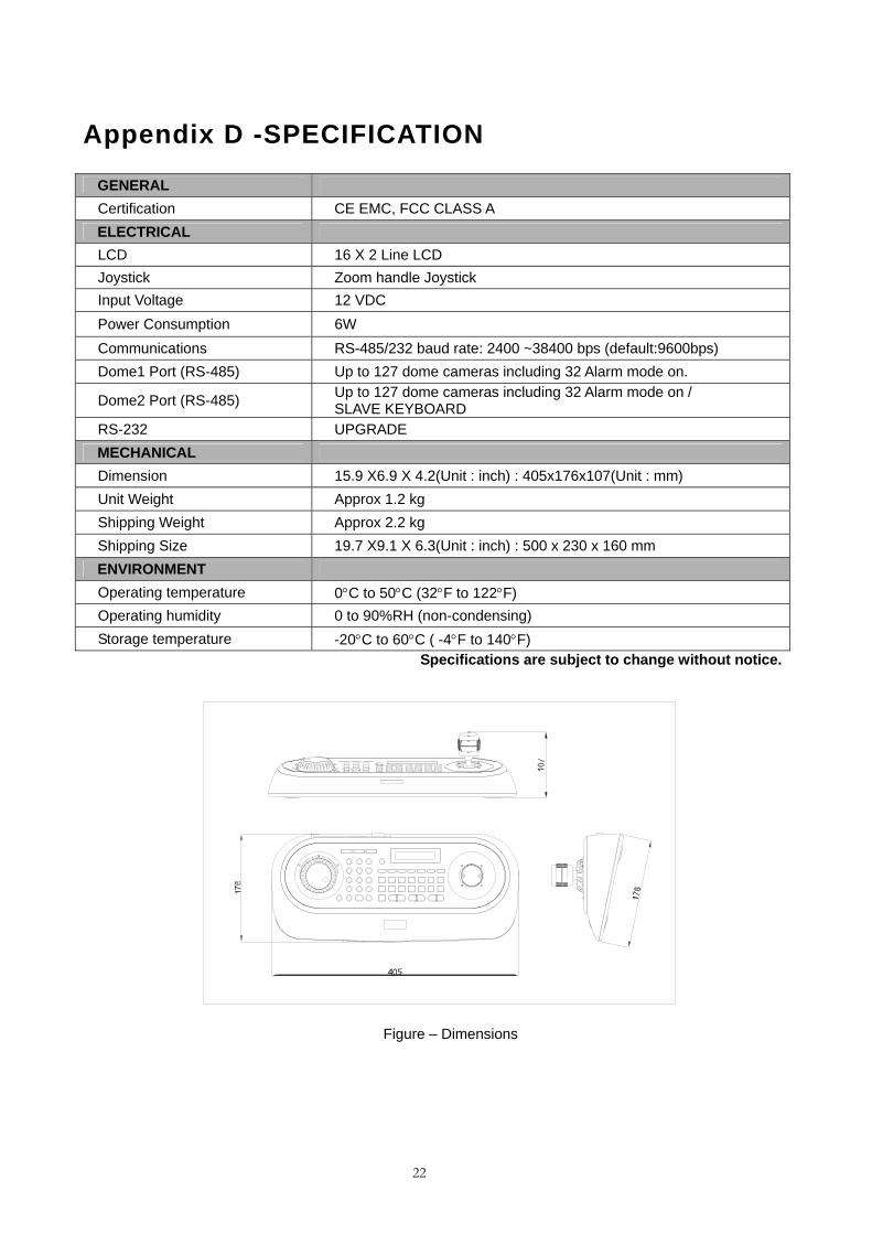
Appendix D -SPECIFICATION
GENERAL Certification CE EMC, FCC CLASS A ELECTRICAL LCD 16 X 2 Line LCD Joystick Zoom handle Joystick Input Voltage 12 VDC Power Consumption 6W Communications RS-485/232 baud rate: 2400 ~38400 bps (default:9600bps) Dome1 Port (RS-485) Up to 127 dome cameras including 32 Alarm mode on.
Dome2 Port (RS-485) Up to 127 dome cameras including 32 Alarm mode on / SLAVE KEYBOARD
RS-232 UPGRADE MECHANICAL Dimension 15.9 X6.9 X 4.2(Unit : inch) : 405x176x107(Unit : mm) Unit Weight Approx 1.2 kg Shipping Weight Approx 2.2 kg Shipping Size 19.7 X9.1 X 6.3(Unit : inch) : 500 x 230 x 160 mm ENVIRONMENT Operating temperature 0°C to 50°C (32°F to 122°F) Operating humidity 0 to 90%RH (non-condensing) Storage temperature -20°C to 60°C ( -4°F to 140°F)
Specifications are subject to change without notice.
Figure – Dimensions
22

MEMO

We welcome your feedback at info@digimerge.com---------------------------------------------For more information, visit www.digimerge.com
North America: 1-866-344-4674
Technical support ( for technical / instal lat ion issues)
Press opt ion 2 for tech support
Mon-Fr i 8.30 am to 7.00pm EST
� BY PHONE:
VE R S I O N 1 - M A R C H , 2007
NEED HELP?
3 Easy Ways To Contact Us
Product support is avai lable 24/7 including product
information, user manuals, quick start up guides and
FAQ’s at www.digimerge.com
ONLINE:�WWW
Please make sure to visit our website www.digimerge.com to receive product updates and information.
Technical support ( for technical / instal lat ion issues)
BY EMAIL:�
at
--

© Digimerge Technology Inc.www.digimerge.com
VISIT / VISITEZ / VISITEwww.digimerge.com
IT’S ALL ON THE WEB!Tout est sur le Web!
¡Todo está en la Web! Product InformationInformation sur le produitInformación acerca del producto
User ManualsGuides de l’utilisateurGuías del usuario
Quick Start GuidesGuides de démarrage rapideGuías de arranque rápido
Specification SheetsFiches signalétiquesFichas de especificaciones
Software UpgradesMises à jour du logicielActualizaciones del programa
Firmware UpgradesMises à jour du micro-logicielActualizaciones del microprograma