advanced software engineering lecture 2: requirement engineering prof. harold liu
TRANSCRIPT
Advanced Software Engineering
Lecture 2: Requirement Engineering
Prof. Harold Liu
Outline Software Requirement Requirement Engineering Requirement Modeling

We Aim to Answer: What is the user requirement, system requirement?
How to express them?
Functional and non-functional requirement
What is SRS? How to write SRS?
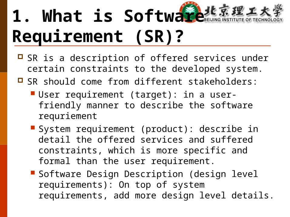
1. What is Software Requirement (SR)?
SR is a description of offered services under certain constraints to the developed system.
SR should come from different stakeholders: User requirement (target): in a user-friendly manner to
describe the software requriement System requirement (product): describe in detail the
offered services and suffered constraints, which is more specific and formal than the user requirement.
Software Design Description (design level requirements): On top of system requirements, add more design level details.
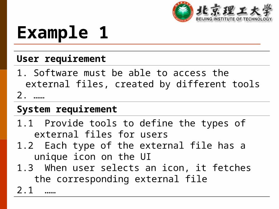
Example 1User requirement1. Software must be able to access the external files, created by
different tools2. ……System requirement1.1 Provide tools to define the types of external files for users1.2 Each type of the external file has a unique icon on the UI1.3 When user selects an icon, it fetches the corresponding
external file2.1 ……
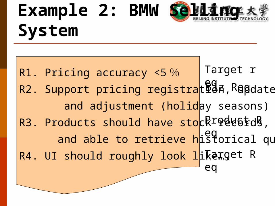
Example 2: BMW Selling System
R1. Pricing accuracy <5%R2. Support pricing registration, update,
and adjustment (holiday seasons)
R3. Products should have stock records,
and able to retrieve historical quotes
R4. UI should roughly look like….
Target req
Biz Req
Product Req
Target Req
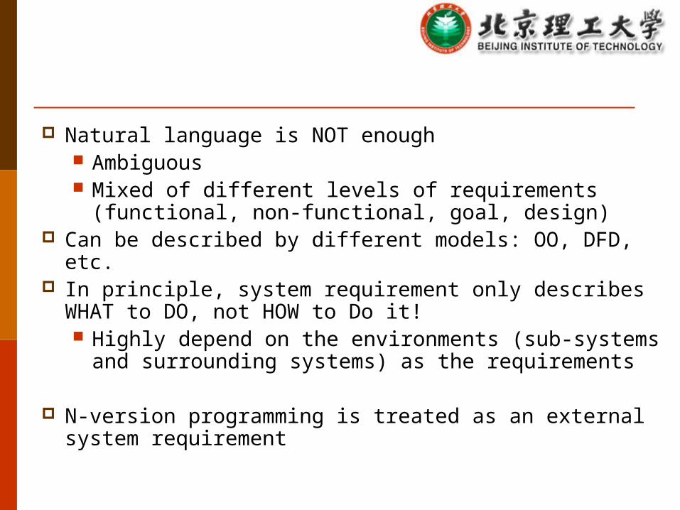
Natural language is NOT enough Ambiguous Mixed of different levels of requirements (functional, non-
functional, goal, design) Can be described by different models: OO, DFD, etc. In principle, system requirement only describes WHAT to DO,
not HOW to Do it! Highly depend on the environments (sub-systems and
surrounding systems) as the requirements
N-version programming is treated as an external system requirement
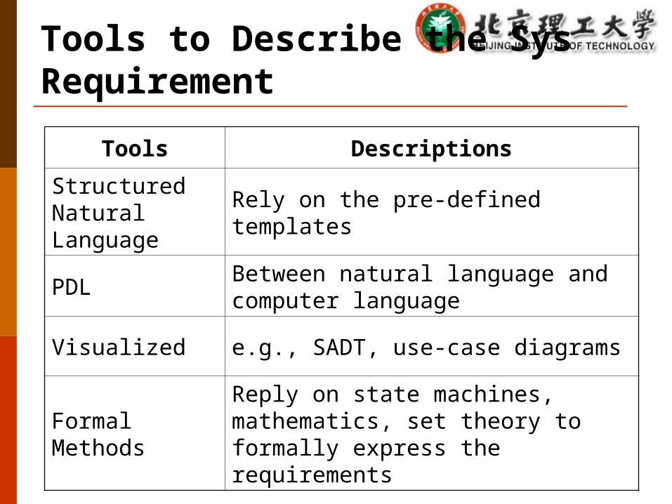
Tools to Describe the Sys Requirement
Tools Descriptions
Structured Natural Language Rely on the pre-defined templates
PDL Between natural language and computer language
Visualized e.g., SADT, use-case diagrams
Formal MethodsReply on state machines, mathematics, set theory to formally express the requirements
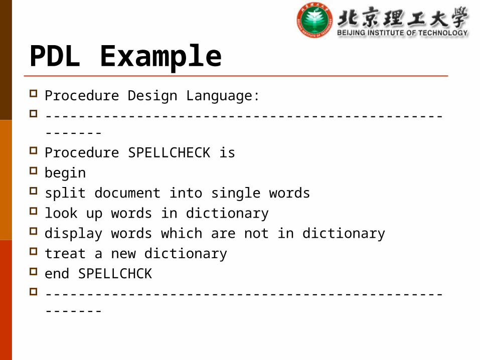
PDL Example Procedure Design Language: ------------------------------------------------------- Procedure SPELLCHECK is begin split document into single words look up words in dictionary display words which are not in dictionary treat a new dictionary end SPELLCHCK -------------------------------------------------------
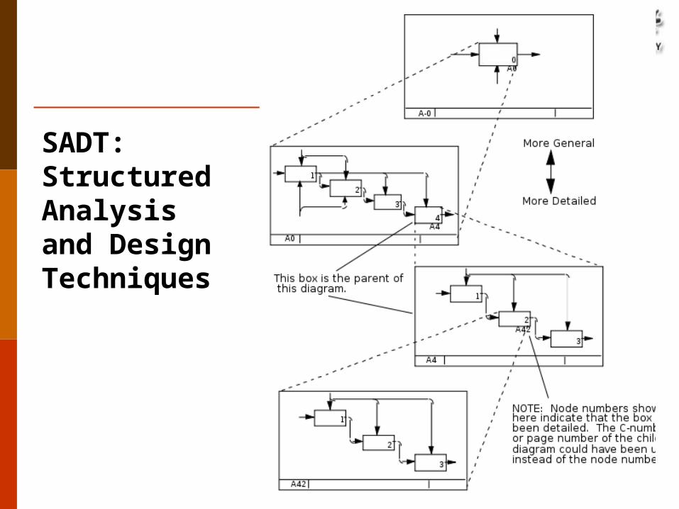
SADT: Structured Analysis and Design Techniques
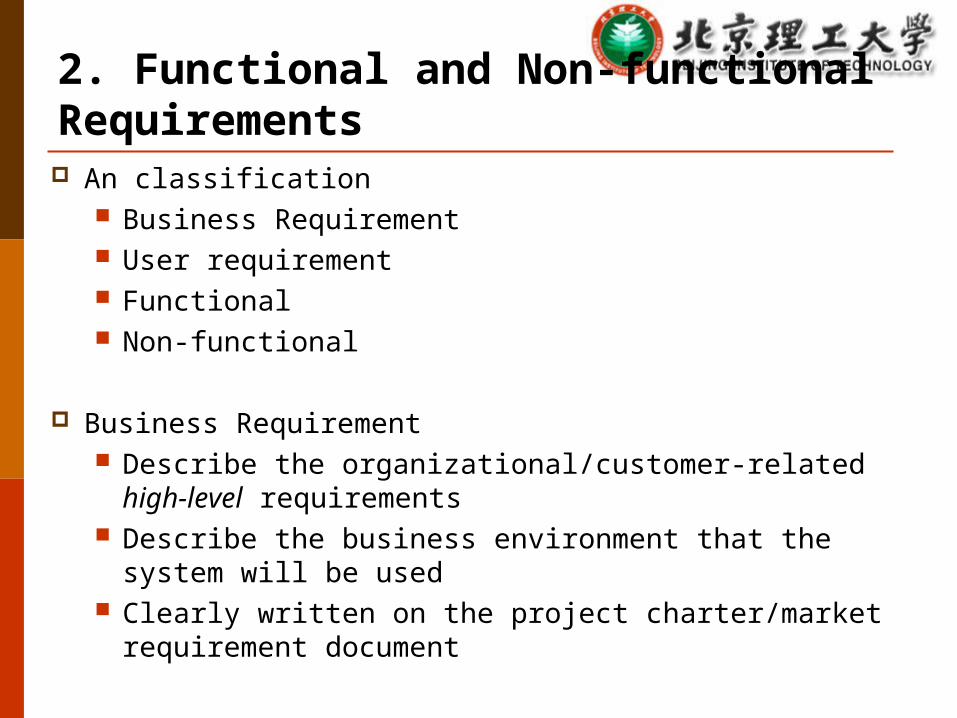
2. Functional and Non-functional Requirements An classification
Business Requirement User requirement Functional Non-functional
Business Requirement Describe the organizational/customer-related high-level
requirements Describe the business environment that the system will be used Clearly written on the project charter/market requirement
document
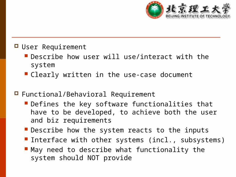
User Requirement Describe how user will use/interact with the system Clearly written in the use-case document
Functional/Behavioral Requirement Defines the key software functionalities that have to be
developed, to achieve both the user and biz requirements Describe how the system reacts to the inputs Interface with other systems (incl., subsystems) May need to describe what functionality the system should
NOT provide

Non-functional Requirement Constraints to the provided functionality/service,
including, performance targets, quality attribute, external APIs, constraint for design and implementations, timing
Some non-functional requirement may not be verified (since they cannot be quantified)
Conflicts with functional requirements Conflicts between non-functional requirements
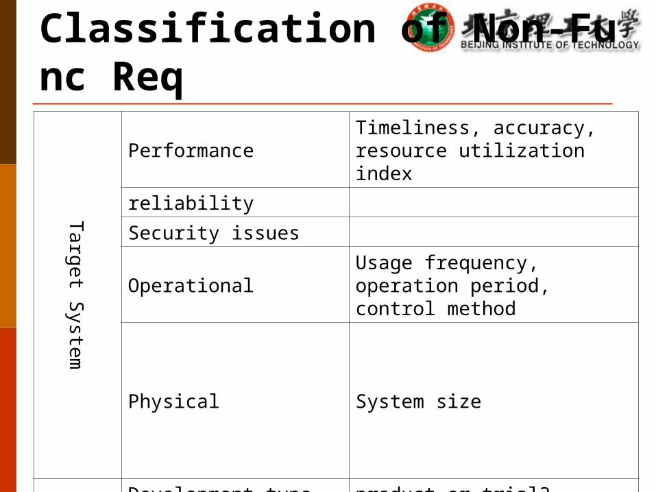
Classification of Non-Func Req
Target System
Performance Timeliness, accuracy, resource utilization index
reliability
Security issues
Operational Usage frequency, operation period, control method
Physical System size
Developm
ent and M
aintenance
Development type product or trial?
Workload estimation
Methodology Quality control, milestones, acceptance criterion
Priority and changeability
maintenance
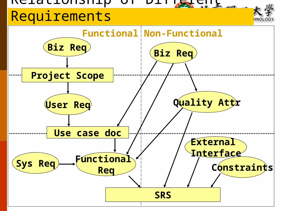
Functional Non-FunctionalBiz Req
User Req Quality Attr
External Interface
Sys Req ConstraintsFunctional
Req
Project Scope
Use case doc
SRS
Biz Req
Relationship of Different Requirements
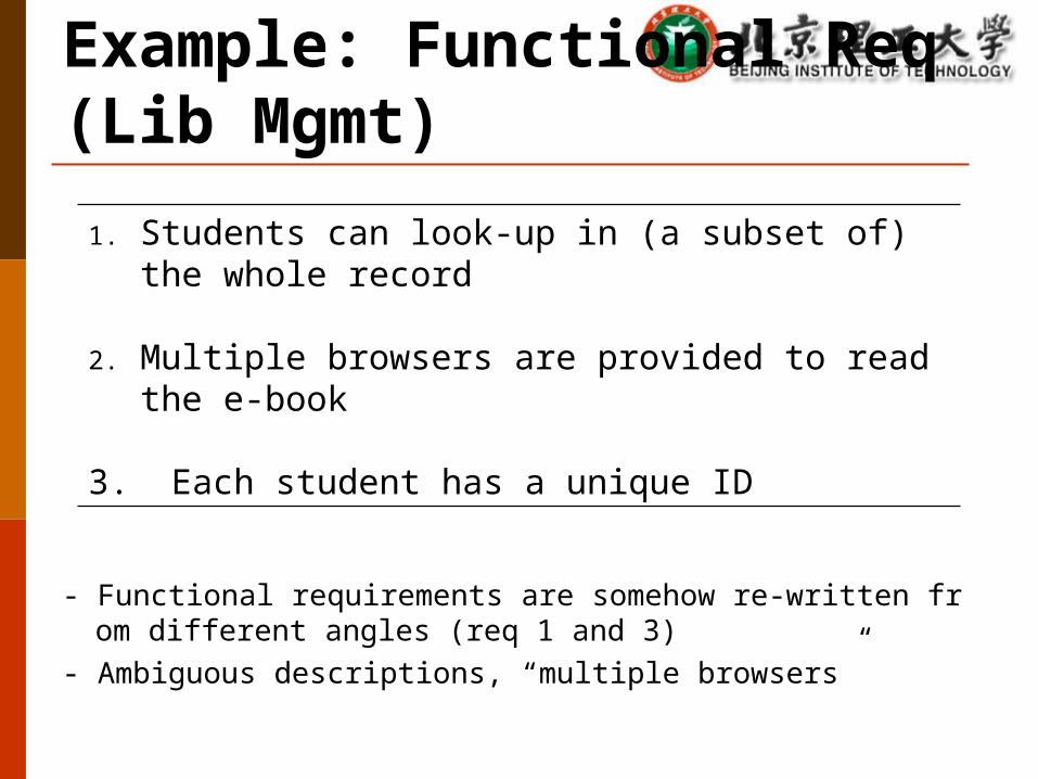
Example: Functional Req (Lib Mgmt)
1. Students can look-up in (a subset of) the whole record
2. Multiple browsers are provided to read the e-book
3. Each student has a unique ID
- Functional requirements are somehow re-written from different angles (req 1 and 3)
- Ambiguous descriptions, “multiple browsers”
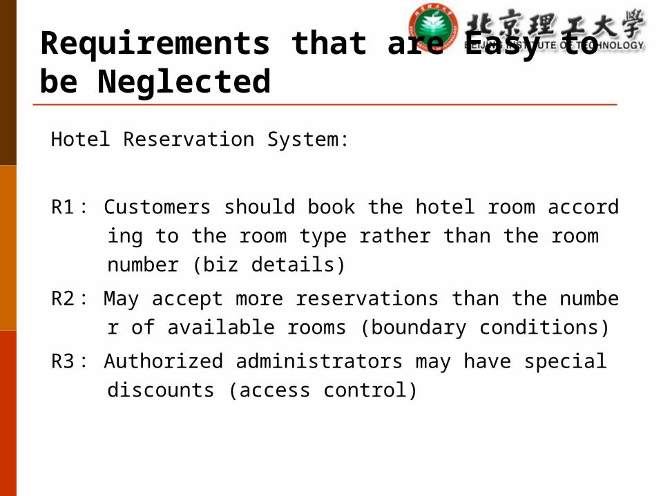
Requirements that are Easy to be Neglected
Hotel Reservation System:
R1: Customers should book the hotel room according to the room type rather than the room number (biz details)
R2:May accept more reservations than the number of available rooms (boundary conditions)
R3: Authorized administrators may have special discounts (access control)
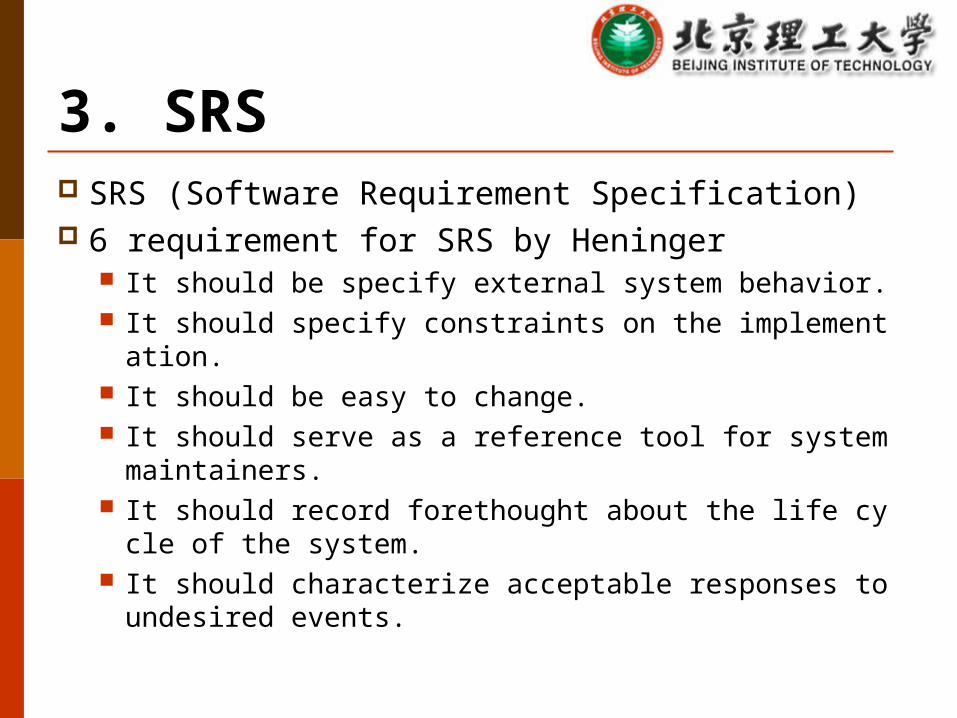
3. SRS SRS (Software Requirement Specification) 6 requirement for SRS by Heninger
It should be specify external system behavior. It should specify constraints on the implementation. It should be easy to change. It should serve as a reference tool for system maintainers. It should record forethought about the life cycle of the syst
em. It should characterize acceptable responses to undesired e
vents.

Introduction Purpose Definitions System overview References
Overall description Product perspective
System Interfaces User Interfaces Hardware interfaces Software interfaces Communication Interfaces Memory Constraints Operations Site Adaptation Requirements
Product functions User characteristics Constraints, assumptions and dependencies
Specific requirements External interface requirements Functional requirements Performance requirements Design constraints
Standards Compliance Logical database requirement Software System attributes
Reliability Availability Security Maintainability Portability
Other requirements
SRS Outline
Outline Software Requirement Requirement Engineering Requirement Modeling
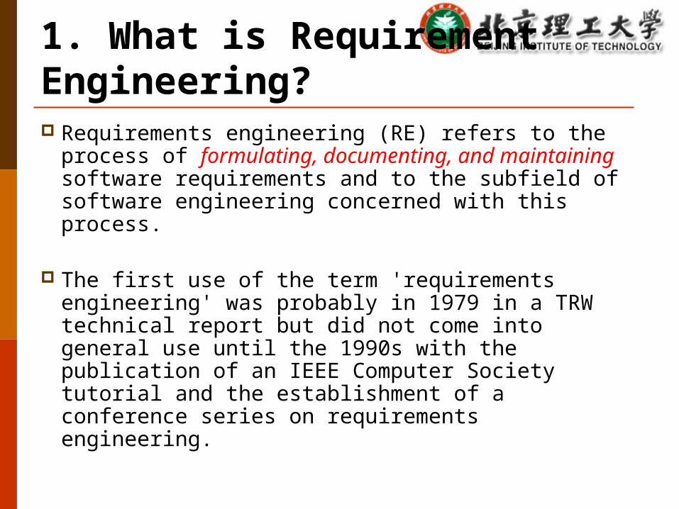
1. What is Requirement Engineering? Requirements engineering (RE) refers to the process
of formulating, documenting, and maintaining software requirements and to the subfield of software engineering concerned with this process.
The first use of the term 'requirements engineering' was probably in 1979 in a TRW technical report but did not come into general use until the 1990s with the publication of an IEEE Computer Society tutorial and the establishment of a conference series on requirements engineering.
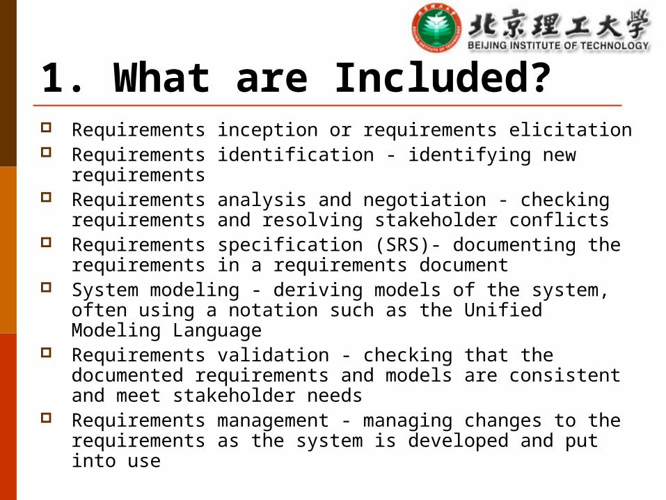
Requirements inception or requirements elicitation Requirements identification - identifying new requirements Requirements analysis and negotiation - checking
requirements and resolving stakeholder conflicts Requirements specification (SRS)- documenting the
requirements in a requirements document System modeling - deriving models of the system, often
using a notation such as the Unified Modeling Language Requirements validation - checking that the documented
requirements and models are consistent and meet stakeholder needs
Requirements management - managing changes to the requirements as the system is developed and put into use
1. What are Included?
Who are Evolved in Requirement Inception?
Contract regulators: propose milestones, constraints and project plan
Customers Users PM: to understand the potential impact and consequence
of the developed system Designers: to propose the acceptable and feasible solution Testers: to make sure the software system satisfy each
requirement in the SRS
Requirement Inception is Important! 40% -60% of the defects of a Software project are coming
from the requirements analysis phase (Davis 1993, Leffingwell 1997)
Identifying and managing the user requirements are the two most problematic issues for sofware projects (ESPITI 1995)
Problems are due to the improper ways of collecting, recording, negotiating and modifying the requirements Informal information gathering Has not specified the desired function Mistaken assumption without prior communications Requirement change without careful investigations
2. Feasibility Study Key issues:
System meets the organization's overall goal? Whether the system can be completed on time and within
budget? Integration with other existing systems?
Tasks: Technological study Economical study Impact on society study Operational study
Feasibility Study Report
(1) Introduction(2) Prerequisite(3) Analysis of existing system(4) Technical feasibility of the proposed system(5) Economic feasibility of the proposed system(6) Social factor analysis(7) Other alternatives(8) Conclusions

3. What information are needed for a SRS?
1) Physical Environment2) Interfaces3) User and Human Factors4) Functionality5) Documentation6) Data7) Resources8) Security9) Quality Assurance
What is the main purpose of the system?
What is the surrounding physical environment ? e.
g., temperature, humidity, interference?
Quantity?
1) Physical Environment
Input from other (multiple) system(s)?
Output to other (multiple) system(s)?
Data format conversion?
Where is the data stored?
2) Interface Description
Who are the users? How many types of the users? Their technical sense? Training needed? To what extend user may misuse the system?
3) User and Human Factors

What does the system work?
When (what regularity) will the system work?
Operational methods?
If the system will change from time being?
Response time, data volume, throughput?
4) Function Description
5) Documents
What docs are needed?
In what format these docs are stored, used, and
revised?
Who are the readers? (technical) Language barriers?
6) Data
I/O data formats? I/O data frequency?
Accuracy?
Volume?
Storage?
7) Resource Description
Materials, labor, financial resources? Development techniques as a pre-requisite?
Physical size?
Project schedule? Deadline?
SW/HW dependencies?
Data access under control? How to isolate data of different users? How to isolate codes of different users and OS? How to do system back up? Where to store the backup? What measures should be taken upon fire, water and theft?
8) Security Issues
If the system must be effectively tested and to isolate faults? Mean Time Between Failure (MTBF)? How long should we restart the system after a failure? How to cope with changes as part of the new design? Maintenance is only to correct errors, or includes system
improvement? System response time? Portability, maintainability? How to demonstrate the system features?
9) Quality Assurance
4. Verify the SRS To make sure the SRS clearly and completely express the required software quality attribute
s To make sure how we call it “qualified”
What to verify? Consistency Requirements are practical? Completeness Efficiency
Method Review and conduct more requirement analysis Test cases (black box test) and User manual Implement a prototype Leveraging tools
5. Requirement Management Requirements management is the process of documenting, analyzing,
tracing, prioritizing and agreeing on requirements and then controlling change and communicating to relevant stakeholders.
It is a continuous process throughout a project. Begins with: the analysis and elicitation of the objectives and
constraints of the organization. Further includes supporting planning for requirements, integrating
requirements and the organization for working with them (attributes for requirements), as well as relationships with other information delivering against requirements, and changes for these.
Three phases: Problem analysis and change description Change analysis and cost analysis Change adopted and implementation
Activities Define the baseline requirement Review the request, and evaluation the potential impact
to make the decision Integrate the approved changes into the project plan Synchronize the project plan and new SRS Find the corresponding solution (design, codes, test
cases) Always track the requirement status and potential new
changes
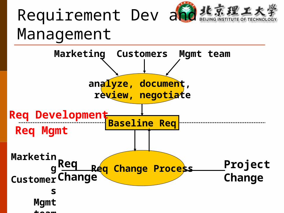
ReqChange
Requirement Dev and Management
analyze, document, review, negotiate
Req Change Process
Baseline Req
Marketing Customers Mgmt team
Req DevelopmentReq Mgmt
MarketingCustomers
Mgmt team
ProjectChange
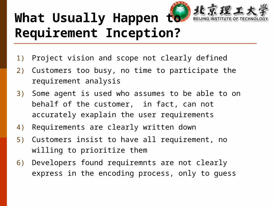
What Usually Happen to Requirement Inception?
1) Project vision and scope not clearly defined
2) Customers too busy, no time to participate the requirement analysis
3) Some agent is used who assumes to be able to on behalf of the customer, in fact, can not accurately exaplain the user requirements
4) Requirements are clearly written down
5) Customers insist to have all requirement, no willing to prioritize them
6) Developers found requiremnts are not clearly express in the encoding process, only to guess
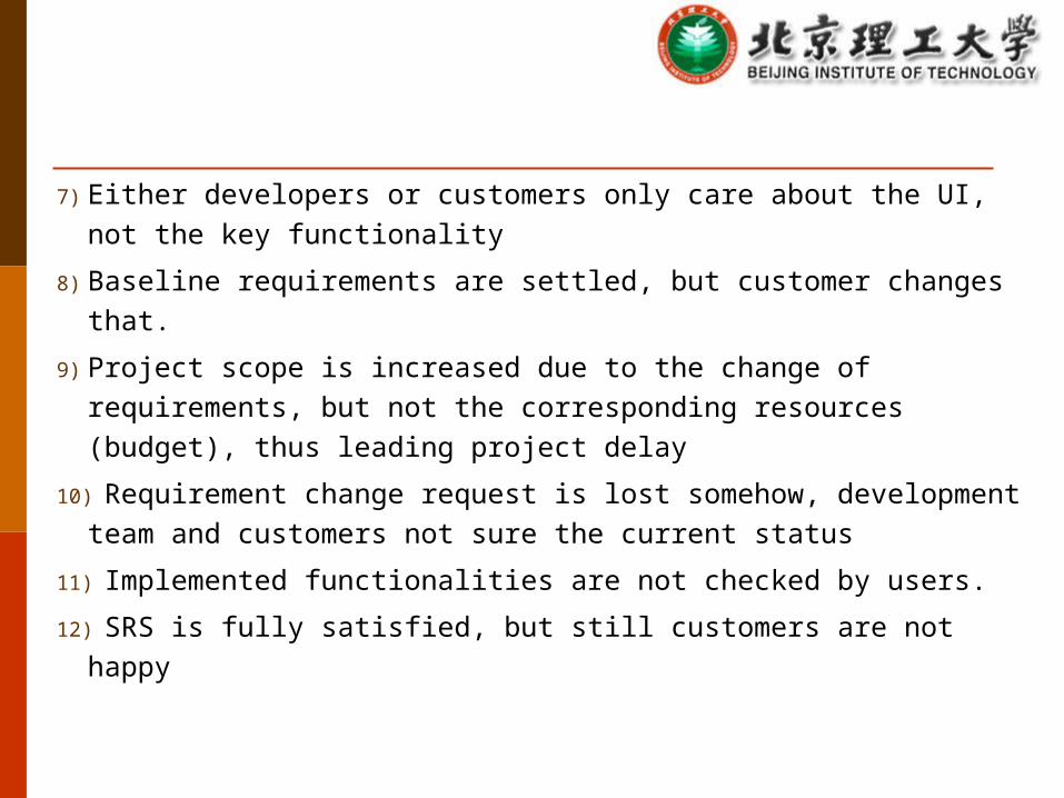
7) Either developers or customers only care about the UI, not the key functionality
8) Baseline requirements are settled, but customer changes that.
9) Project scope is increased due to the change of requirements, but not the corresponding resources (budget), thus leading project delay
10) Requirement change request is lost somehow, development team and customers not sure the current status
11) Implemented functionalities are not checked by users.
12) SRS is fully satisfied, but still customers are not happy
Outline Software Requirement Requirement Engineering Requirement Modeling

Models Do NOT include the implementation details.
Contextual model: e.g., use-case model State machine model: to describe the system behavior in
response of both the internal and external events. Structural model: e.g., architectural design and data
structures Data flow model: to describe how the inputs are
flowing/processed in the system, somehow can correspond to the contextual model (system contexts)
E-R Model for database UML for OO
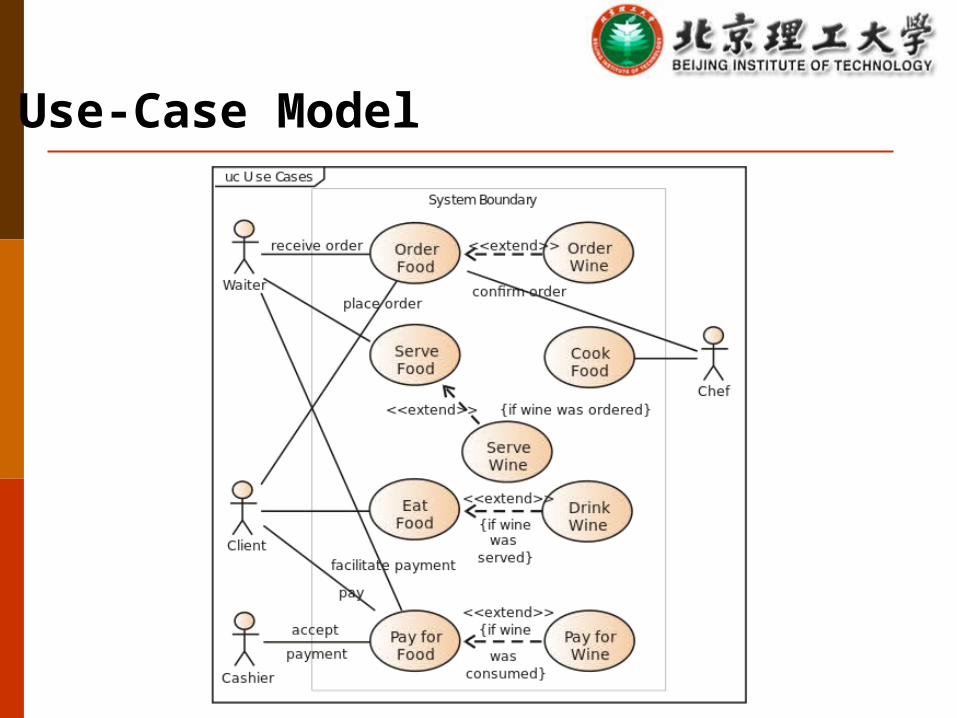
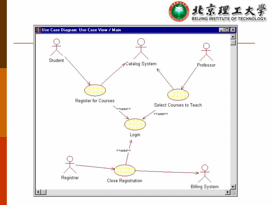
Use-Case Model
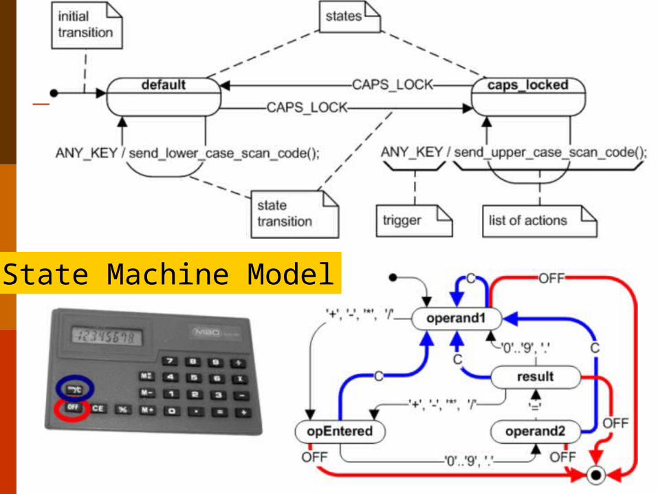
State Machine Model
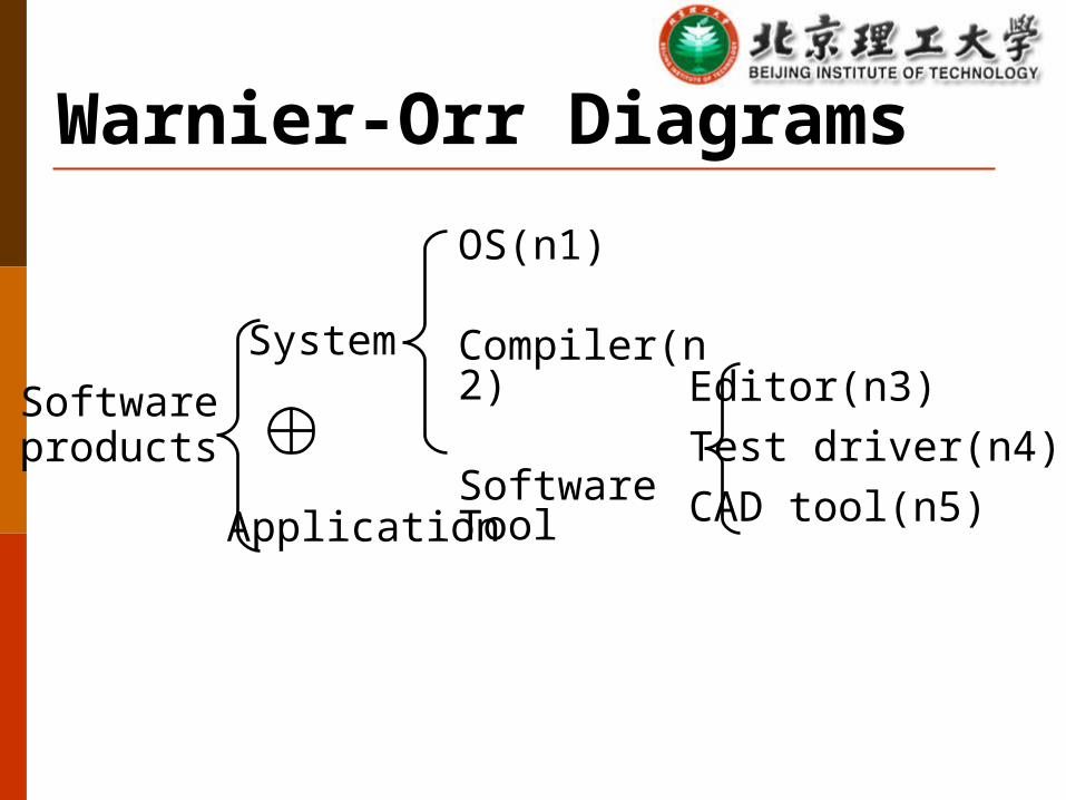
Warnier-Orr Diagrams
Softwareproducts
System
Application
OS(n1)
Compiler(n2)
Software ToolEditor(n3)Test driver(n4)CAD tool(n5)

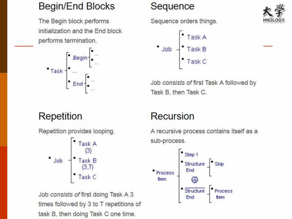
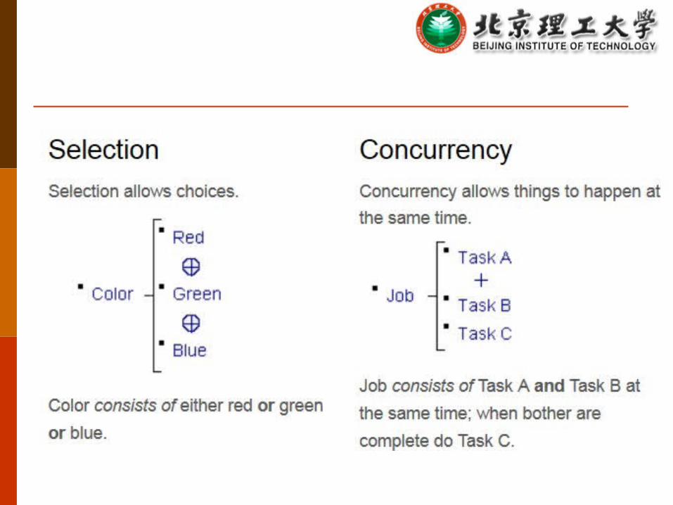
Eight Fundamental Building Blocks

IPO Diagrams
Oldmasterfiles
Otherfiles
Input Process OutputVerifyPrimaryRecord
VerifyOtherRecord
Updaterecord
ValidPrimaryRecord
ValidOtherRecord
Updatedfiles
Entity-Relationship Model Originally proposed by Peter Chen's 1976 paper Process of describing the data, relationships between
the data, and the constraints on the data. The focus is on the data, rather than on the processes. The output of the conceptual database design is a
Conceptual Data Model (+Data Dictionary)
ER Modeling is a top-down approach to database design.
Entity Relationship (ER) Diagram A detailed, logical representation of the entities, associations
and data elements for an organization or business Notation uses three main constructs
Data entities Relationships Attributes
Chen Model & Crow’s Foot Model
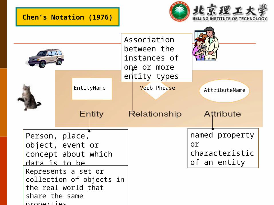
Person, place, object, event or concept about which data is to be maintained
named property or characteristic of an entity
Association between the instances of one or more entity types
Represents a set or collection of objects in the real world that share the same properties
Chen’s Notation (1976)
EntityName Verb Phrase AttributeName
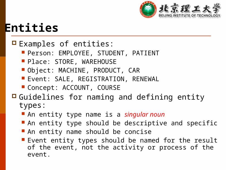
Examples of entities: Person: EMPLOYEE, STUDENT, PATIENT Place: STORE, WAREHOUSE Object: MACHINE, PRODUCT, CAR Event: SALE, REGISTRATION, RENEWAL Concept: ACCOUNT, COURSE
Guidelines for naming and defining entity types: An entity type name is a singular noun An entity type should be descriptive and specific An entity name should be concise Event entity types should be named for the result of the
event, not the activity or process of the event.
Entities
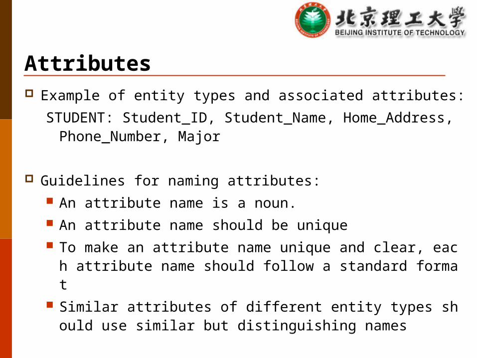
Attributes Example of entity types and associated attributes:
STUDENT: Student_ID, Student_Name, Home_Address, Phone_Number, Major
Guidelines for naming attributes: An attribute name is a noun. An attribute name should be unique To make an attribute name unique and clear, each attribute
name should follow a standard format Similar attributes of different entity types should use similar
but distinguishing names
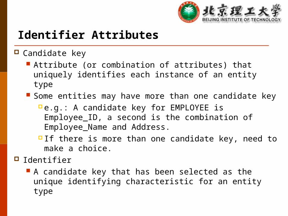
Identifier Attributes Candidate key
Attribute (or combination of attributes) that uniquely identifies each instance of an entity type
Some entities may have more than one candidate key e.g.: A candidate key for EMPLOYEE is Employee_ID, a
second is the combination of Employee_Name and Address.
If there is more than one candidate key, need to make a choice.
Identifier A candidate key that has been selected as the unique
identifying characteristic for an entity type

Relationships
Associations between instances of one or more entity types that is of
interest Given a name that describes its function.
• relationship name is an active or a passive verb.
Associations between instances of one or more entity types that is of
interest Given a name that describes its function.
• relationship name is an active or a passive verb.
Author Book
Relationship name: writes
An author writes one or more booksA book can be written by one or more authors.
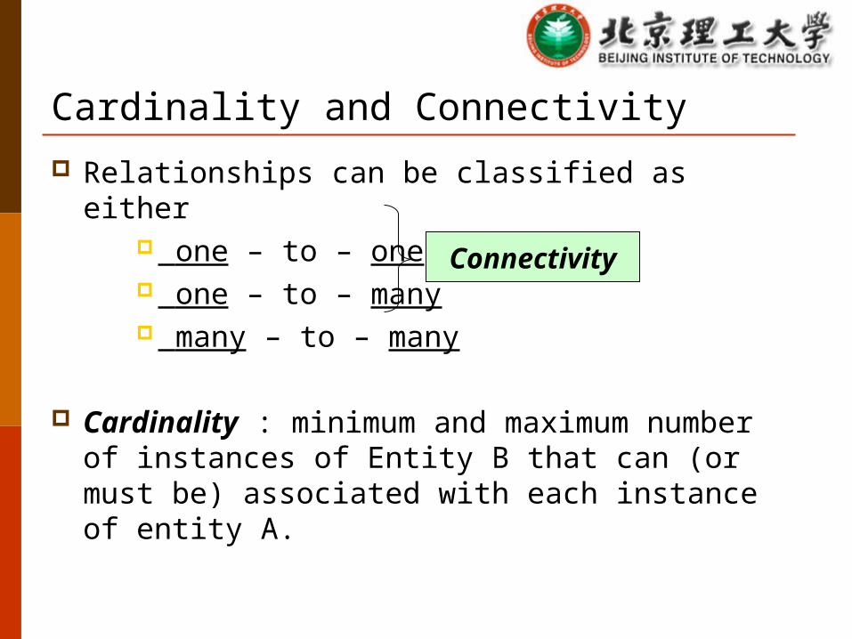
Cardinality and Connectivity Relationships can be classified as either
one – to – one one – to – many many – to – many
Cardinality : minimum and maximum number of instances of Entity B that can (or must be) associated with each instance of entity A.
Connectivity
Connectivity
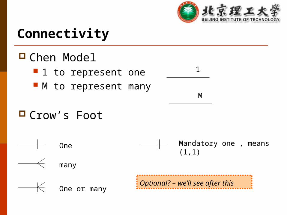
Chen Model 1 to represent one M to represent many
Crow’s Foot
many
One
One or many
1
M
Mandatory one , means (1,1)
Optional? – we’ll see after this
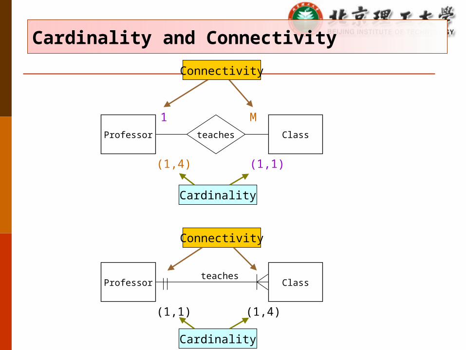
Cardinality and Connectivity
Professor Classteaches
Professor Classteaches
1 M
Connectivity
Connectivity
(1,1)
(1,1)
(1,4)
(1,4)
Cardinality
Cardinality
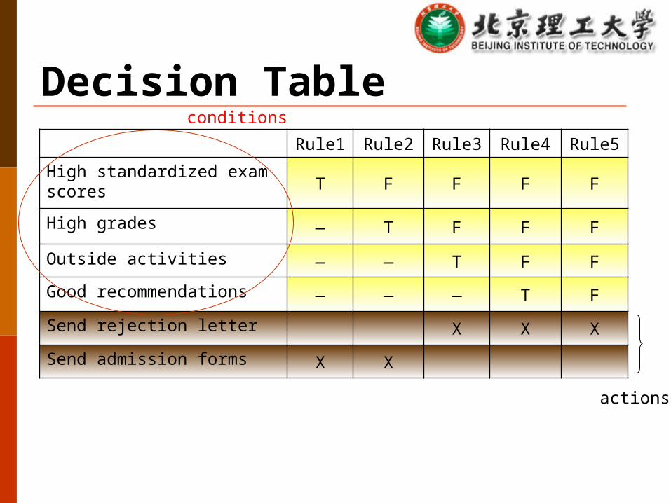
Decision TableRule1 Rule2 Rule3 Rule4 Rule5
High standardized exam scoresT F F F F
High grades — T F F F
Outside activities — — T F F
Good recommendations — — — T F
Send rejection letter X X X
Send admission forms X X
actions
conditions

Functional Descriptions
kji SCSf ,
StateSi
StateSk
Condition, Cj
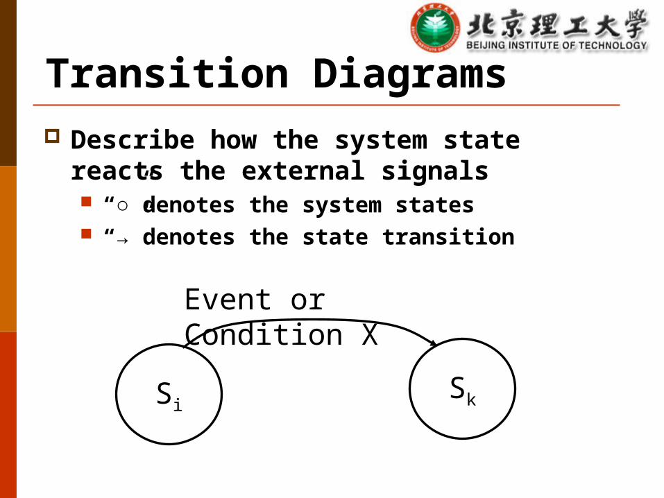
Transition Diagrams
SiSk
Event or Condition X
Describe how the system state reacts the external signals “○”denotes the system states “→”denotes the state transition
Benefits Clearly shows the system state transitions Easy to use analysis tools

Fence Diagram showing State Transitions (Hotel reservations)
(Null)Requested
On waiting list
Confirmed
UsedCanceledArchive
Use UML to Represent OO OMG (Object Management Group) have adopted
UML as the OO notational standard. UML can be used to visualize, specify, or document a
problem. UML can be used throughout the software
development process.
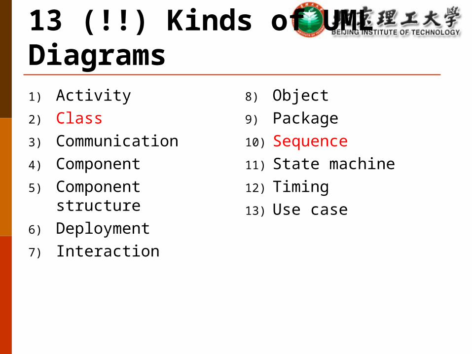
13 (!!) Kinds of UML Diagrams1) Activity2) Class3) Communication4) Component5) Component structure6) Deployment7) Interaction
8) Object9) Package10) Sequence11) State machine12) Timing13) Use case
69
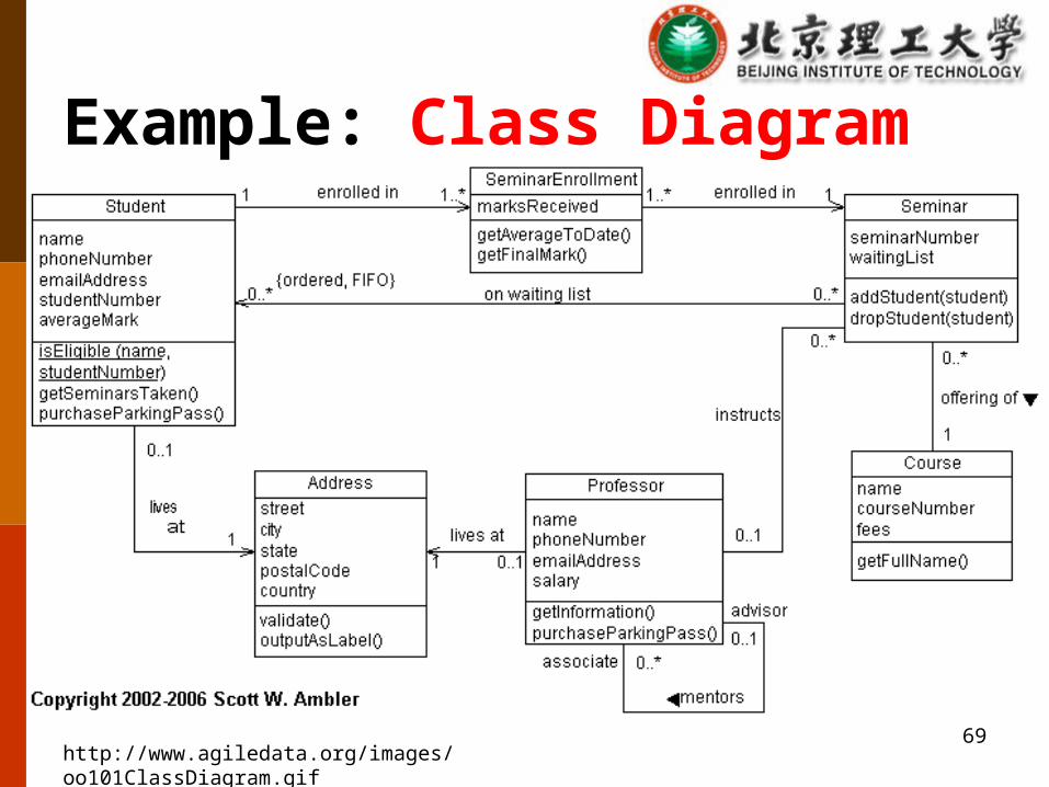
Example: Class Diagram
http://www.agiledata.org/images/oo101ClassDiagram.gif
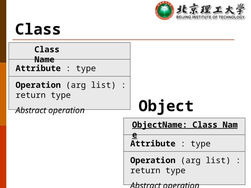
ClassClass Name
Attribute : type
Operation (arg list) : return type
Abstract operation ObjectObjectName: Class Name
Attribute : type
Operation (arg list) : return type
Abstract operation

Role of A
Role of B
EdgesClass A Class B
Source TargetRole name
Client SupplierDependency
Navigability
Association
Role name
Multiplicities on Edges (Cardinalities)1 Exactly one* Many (any number)0..1 Optional (zero or one)m..n Specified range{ordered}* Ordered
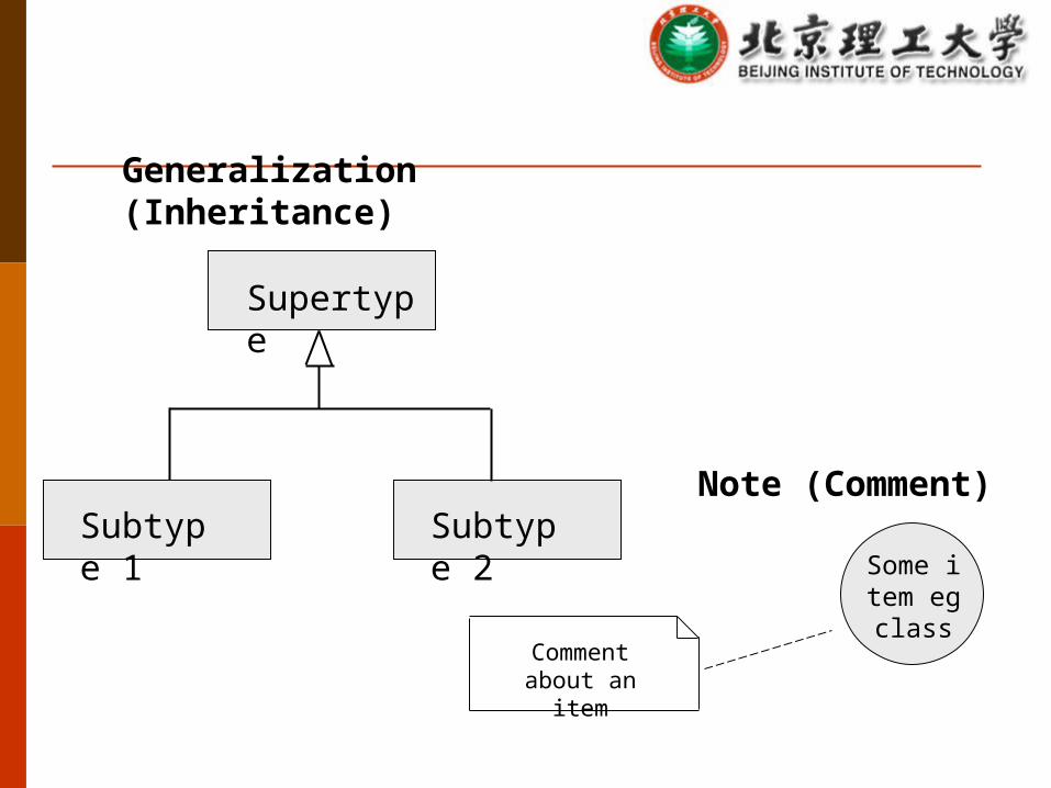
Generalization (Inheritance)
Supertype
Subtype 1 Subtype 2
Comment about an item
Some item eg class
Note (Comment)
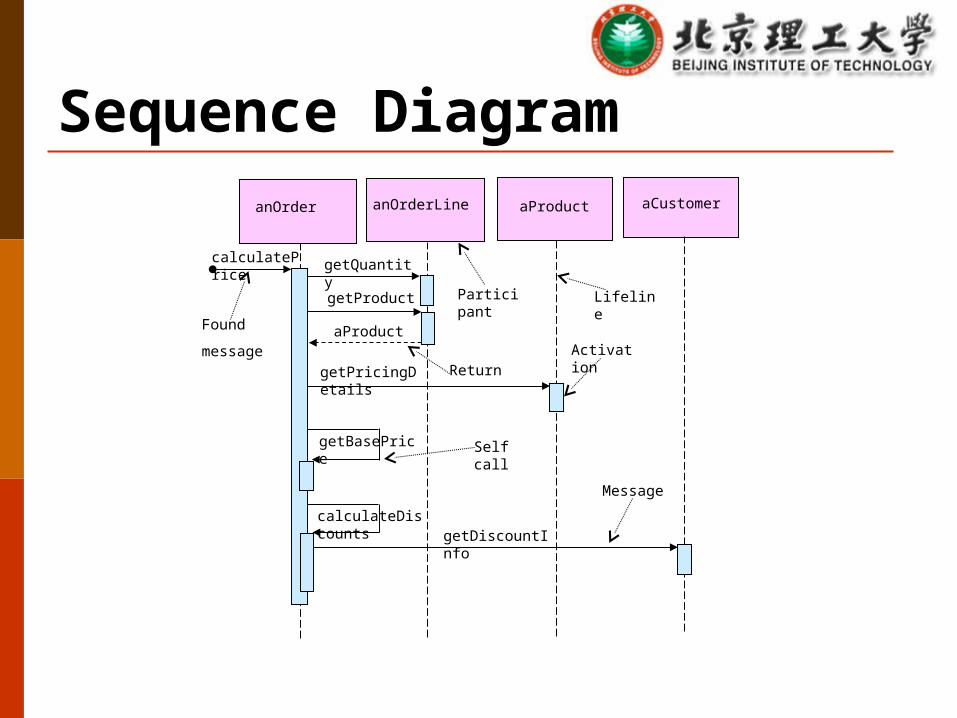
Sequence DiagramanOrder anOrderLine aProduct aCustomer
calculatePrice getQuantity
getProduct
getPricingDetails
getBasePrice
calculateDiscountsgetDiscountInfo
aProductFound
message
Participant Lifeline
ReturnActivation
Self call
Message
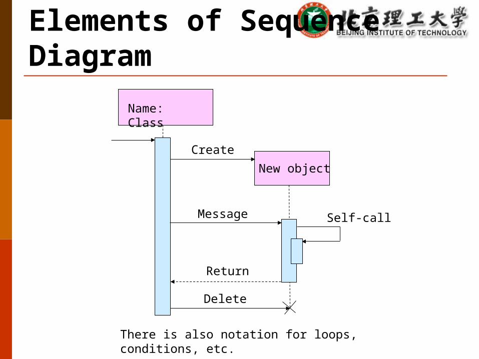
Elements of Sequence Diagram
There is also notation for loops, conditions, etc.
Name: Class
New object
Create
Message
Return
Delete
Self-call
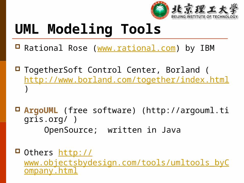
UML Modeling Tools Rational Rose (www.rational.com) by IBM
TogetherSoft Control Center, Borland (http://www.borland.com/together/index.html)
ArgoUML (free software) (http://argouml.tigris.org/ ) OpenSource; written in Java
Others http://www.objectsbydesign.com/tools/umltools_byCompany.html

Rational RoseStandardToolbar
Browser
DocumentationWindow
Diagram WindowDiagram Toolbar
StatusBar