advanced transportation management system (atms) city of mississauga feb 15... · advanced...
TRANSCRIPT

Advanced Transportation
Management System (ATMS)Presentation to the
ITS Technology Workshop for Municipalities
February 15, 2017

ATMS Project Background
• Increasing traffic volumes– Roadway network is near capacity, and in some areas,
at capacity during am/pm peak periods.
• Increased urbanization
• Other transportation agencies– Need to integrate our efforts with Region of Peel/MTO
who are also stakeholders in the transportation network.

ATMS Project Background
• Public expectations
– The public expects the City to provide an efficient
transportation network, to be able to respond to issues,
and to provide timely/accurate information.

ATMS Project Background
• Operational needs– The existing Traffic Control System is at the end of its
life cycle and needs replacement.
– There is a need to upgrade to a more robust traffic signal communication.
– A Traffic Management Centre is needed to provide staff with the workspace/resources to pro-actively manage traffic.

ATMS Project Background
• The Advanced Transportation Management
System (ATMS) Project provides a means to meet
our operational needs and the expectations of the
public.

ATMS Project Vision
• To move from “passive” to “active” management.

ATMS Project Goals
• Maximize the available capacity of the roadway
network
• Minimize the impact of roadway incidents to users
• Pro-actively manage traffic
• Assist in the provision of emergency services
• Create and maintain public confidence in traffic
management

A well designed ATMS will make it possible to:
• Monitor travel conditions
• Influence the operation of traffic signals
• Disseminate information
• Interact with other transportation modes and
agencies

ATMS Project Components
The following components are in various stages:
1. Build a Traffic Management Centre (TMC)
2. Upgrade traffic signal communications
3. Replace the traffic control system
4. Implement Intelligent Transportation Systems (ITS)
5. Explore future ATMS initiatives

1. Traffic Management Centre (TMC)
• The design and construction of a physical central
space where traffic staff can monitor and respond
to traffic.
• This component of the project is substantially
complete.


1. Traffic Management Centre
Before After

2. Traffic Signal Communications• Leverage the City’s Ethernet IP Network
– Hybrid of wired fibre, Wi-Fi and cellular
• 120 traffic signals have migrated to the new communication network
• Remaining signals to be completed by the end of 2018

Public Sector Network
(PSN)

What’s at an intersection?
Intersection of Burnhamthorpe Rd & Central Parkway

19
Typical Fibre & Wireless Communication
Scenario at an intersection

The “IT Cabinet” connects the devices at
the
intersection to the City’s fibre network
Network switch
Power
Fibre

What’s up on the pole?
Traffic Cameras & Wireless Access
Points

It starts with fibre nodes …

Then we add WIFI access points …

Finally, we spread the coverage …(which enables the Internet of Things (IoT)
Any network-connected device can be added in the
future

3. Traffic Control System Replacement
• Replace Traffic Control
System
• Replace Traffic Signal
Controllers in the field

3. Traffic Control System Replacement
Objectives: • Accommodate future modules and technology advancements (ex.
traveler information)
• Ability to share information with the Region of Peel, MTO and
neighbouring municipalities
• Ability to integrate with Transit and Fire (ex. traffic signal priority)
• Use the City’s network to communicate to Traffic Signal Controllers
and other devices (ex. traffic cameras)
• Pro-actively manage traffic signals

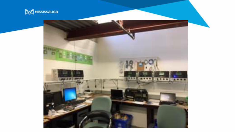
3. Traffic Control System ReplacementStep 1: Install new system
Parsons iNet System Selected
Installed on City Servers
Tested against an approved Acceptance Plan
Tested on 10 bench controllers ( 3 ATC CU’s )
Documentation and training
3. Traffic Control System ReplacementStep 2: Proof of Concept
Deploy to 30 Intersections in the field
Operate the System as Normal
Document Performance
Report Anomalies
Establish / Re-create Processes
Select the System Controller Unit (Timer)

3. Traffic Control System ReplacementStep 3: Full Deployment
Establish the process ( 760 intersections to deploy)
Flowchart ( story board )
Group together “ tasks “ from the flowchart
Establish Realistic Timelines for Each Task
Divide Related Tasks into Realistic Time Blocks
Established a 6 Week Deployment Cycle
Capable of Deploying 10 Intersections per Week

3. Traffic Control System ReplacementStep 3: Full Deployment
Establish the process ( 760 intersections to deploy)
flowchart ( story board )
Group together “ tasks “ from the flowchart
establish realistic timelines for each task
divide related tasks into realistic time blocks
Established a 6 Week deployment cycle
Capable of deploying 10 Intersections per week

CU Delivery Date Deployment Feb. 9, 2017
Batch 1 Complete
14-Nov wk1
5 CU's arr 21-Nov wk2
28-Nov wk3
05-Dec wk4 Batch 2 Complete
12-Dec wk5 wk1 Batch 3 Complete
70 CU's arr 19-Dec wk6 wk2 wk1
26-Dec 5
02-Jan wk3 wk2 Batch 4
09-Jan wk4 wk3 wk1 Batch 5
16-Jan wk5 wk4 wk2 wk1 Batch 6
23-Jan wk6 wk5 wk3 wk2 wk1 Batch 7
30-Jan 10 wk6 wk4 wk3 wk2 wk1 Batch 8
75 CU's arr 06-Feb 10 wk5 wk4 wk3 wk2 wk1 Batch 9
13-Feb wk6 wk5 wk4 wk3 wk2 wk1 Batch 10
20-Feb 10 wk6 wk5 wk4 wk3 wk2 wk1 Batch11
27-Feb 11 wk6 wk5 wk4 wk3 wk2 wk1 Batch 12
75 CU's arr 06-Mar 10 wk6 wk5 wk4 wk3 wk2 wk1 Batch 13
13-Mar 10 wk6 wk5 wk4 wk3 wk2 wk1 Batch 14
20-Mar Batch 15 10 wk6 wk5 wk4 wk3 wk2 wk1
27-Mar wk1 Batch 16 10 wk6 wk5 wk4 wk3 wk2
75 CU's arr 03-Apr wk2 wk1 Batch 17 10 wk6 wk5 wk4 wk3
10-Apr wk3 wk2 wk1 Batch 18 10 wk6 wk5 wk4
17-Apr wk4 wk3 wk2 wk1 Batch 19 10 wk6 wk5
24-Apr wk5 wk4 wk3 wk2 wk1 Batch 20 10 wk6
75 CU's arr 01-May wk6 wk5 wk4 wk3 wk2 wk1 Batch 21 10
08-May 10 wk6 wk5 wk4 wk3 wk2 wk1 Batch 22
15-May 10 wk6 wk5 wk4 wk3 wk2 wk1 Batch 23
22-May 10 wk6 wk5 wk4 wk3 wk2 wk1 Batch 24
29-May 10 wk6 wk5 wk4 wk3 wk2 wk1 Batch 25
75 CU's arr 05-Jun 10 wk6 wk5 wk4 wk3 wk2 wk1 Batch 26
12-Jun 10 wk6 wk5 wk4 wk3 wk2 wk1 Batch 27
19-Jun 10 wk6 wk5 wk4 wk3 wk2 wk1 Batch 28
26-Jun 10 wk6 wk5 wk4 wk3 wk2 wk1
75 CU's arr 03-Jul 10 wk6 wk5 wk4 wk3 wk2
10-Jul 10 wk6 wk5 wk4 wk3
17-Jul 10 wk6 wk5 wk4
24-Jul 10 wk6 wk5
31-Jul 10 wk6
07-Aug 10
Christmas Week
1) Cawthra Rd. @ South Service Rd.
2) Cawthra Rd. @ QEW E/B Off Ramp (South Terminal)
3) Cawthra Rd. @ QEW W/B Off Ramp (North Terminal)
4) Cawthra Rd. @ North Service Rd.
5) South Service Rd. @ Ogden Ave.
6) South Service Rd. @ Haig Blvd. / Dixie Mall Access
7) South Service Rd. @ Dixie Plaza Access
8) North Service Rd. @ Stanfield Rd.
9) Dixie Rd. @ Rometown Dr. / Mall Access
10) Dixie Rd. @ South Service Rd.

Weekly Activities
Publish
Send notification e-mail
Week One
Collect Intersection Data
Send Intersection Data to Parsons
Detail Communication Requirements to IT
Week Two
Parsons builds Database
Prepare CU Field Installation Checklist
Week Three
Receive DB from Parsons
Receive Cell Modems
CU Burn in
Week Four
Bench Test CU
Collect Required Field Equipment
Week Five
Complete Pre CU Installation
Define Intersection on iNET
Week Six
Complete CU Field Installation
Complete Central Confirmation


CU Delivery Date Deployment
Batch 1 Complete
14-Nov wk1
5 CU's arr 21-Nov wk2
28-Nov wk3
05-Dec wk4 Batch 2 Complete
12-Dec wk5 wk1 Batch 3 Complete
70 CU's arr 19-Dec wk6 wk2 wk1
26-Dec 5
02-Jan wk3 wk2 Batch 4
09-Jan wk4 wk3 wk1 Batch 5
16-Jan wk5 wk4 wk2 wk1 Batch 6
23-Jan wk6 wk5 wk3 wk2 wk1 Batch 7
30-Jan 10 wk6 wk4 wk3 wk2 wk1
75 CU's arr 06-Feb 10 wk5 wk4 wk3 wk2
13-Feb wk6 wk5 wk4 wk3
20-Feb 10 wk6 wk5 wk4
27-Feb 11 wk6 wk5
75 CU's arr 06-Mar 10 wk6
Christmas Week
1) Cawthra Rd. @ South Service Rd.
2) Cawthra Rd. @ QEW E/B Off Ramp (South Terminal)
3) Cawthra Rd. @ QEW W/B Off Ramp (North Terminal)
4) Cawthra Rd. @ North Service Rd.
5) South Service Rd. @ Ogden Ave.
6) South Service Rd. @ Haig Blvd. / Dixie Mall Access
7) South Service Rd. @ Dixie Plaza Access
8) North Service Rd. @ Stanfield Rd.
9) Dixie Rd. @ Rometown Dr. / Mall Access
10) Dixie Rd. @ South Service Rd.

4. Intelligent Transportation Systems (ITS)
• ITS involves the use of smart technologies.
• Currently, 38 traffic monitoring cameras set-
up along high profile corridors.– Target: 150 cameras throughout the City in the long
term
• Piloting new detection technology (i.e.
Radar) to detect vehicles, bicycles and
pedestrians.

4. Intelligent Transportation Systems• ATMS Demonstration to take place along
Dundas Street (Ninth Line to Mississauga Road)
• Test and evaluate different traffic management technologies (ex. adaptive traffic control, incident management, traveller information)
• Targeted to start in 2017

City of Mississauga – ATMS Solution: Work Package #4 – ATMS Demonstration
WP#4 OVERVIEW
• Intelligent Traffic Responsive Control of 13 Intersections
• Adaptive Signal Control of 13 Intersections
• VISSIM Micro-simulation Model of Corridor (3 Time Periods)
• Travel Time:
Travel Time Detection with Bluetooth Readers
Display of Travel Times on Trail Blazer Signs
40

City of Mississauga – ATMS Solution: Work Package #4 – ATMS Demonstration
WP#4 OVERVIEW
• Arterial VMS (Optional)
• iNET Incident Management Module
Enter and Track Events
Provide Selection of Timing Plan Patterns
• Integration with 5 City CCTV Traffic Cameras
• Integration with MTO COMPASS Video Feed and Event Feed
41

City of Mississauga – ATMS Solution: Work Package #4 – ATMS Demonstration
Intelligent Traffic Responsive Control (iRC)
• Monitors Historical and Current Traffic Flow Characteristics, and Identifies Unusual Traffic Congestion
• During “Normal” Recurrent Traffic Conditions:
Implements Scheduled Time Based Operations (TBC)
• During Non-recurrent Traffic Congestion Conditions:
Implements Suitable Timing Plan
• Timing Plans Selections include:
No Plan (TBC) Inbound Plan (AM Peak) Outbound Plan (PM Peak) Balanced Congestion Plan Event Plan
• Polls Detector Data on Periodic Intervals, Processes, and Compares to Historical Data (e.g., every 5 min)
42

City of Mississauga – ATMS Solution: Work Package #4 – ATMS Demonstration
iRC – Detector Requirements
• Required Data: Volume and Occupancy
Data used to Identify Historical and Current Traffic Flow Characteristics
e.g., Inbound, Outbound, Balanced
• Locations: Mid-block or Link Entry
Located Upstream of where Recurrent Queues Typically Extend
Corridor Entry Locations
Downstream of Major Traffic Sources / Major Intersections
43

City of Mississauga – ATMS Solution: Work Package #4 – ATMS Demonstration
iRC – Detector Requirements
44

City of Mississauga – ATMS Solution: Work Package #4 – ATMS Demonstration
Adaptive Signal Control (ASC)
• Cycle-by-cycle Traffic Measurements & Signal Timing Updates
Designed Based on Predicting Traffic Trend
• Modifies Current Timing Plan CSO Values
Controllers Still Operate with Existing Local VA
• Once per Cycle, iNET/ASC:
Uploads Traffic Volumes per Movement per Phase for Past Cycle
45

City of Mississauga – ATMS Solution: Work Package #4 – ATMS Demonstration
Adaptive Signal Control (ASC)
• In Current Cycle, Central Algorithms:
Calculate Sat. Flows per Lane for Past Cycle (Stop Line Detectors)
Predict Traffic Volumes for Next Cycle
Optimize & Download Cycle, Splits and Offsets for Next Cycle
Download Small Increment Changes to CSOs
• Controller Implements Updated CSOs at Top of Next Cycle
46

City of Mississauga – ATMS Solution: Work Package #4 – ATMS Demonstration
ASC – Detector Requirements
• Locations: Stop Line
Data primarily used to Optimize Cycle Lengths & Green Splits
Major Multi-phase Intersections
Measure Left and Thru Movements
• Locations: Link Entry
Data primarily used to Improve Downstream Traffic Predictions
Corridor Entry Locations
Upstream of Major Intersections
Measure Demand to Major Intersection
• No Detectors at Very Minor Intersections
47

City of Mississauga – ATMS Solution: Work Package #4 – ATMS Demonstration
ASC – Detector Requirements
48

City of Mississauga – ATMS Solution: Work Package #4 – ATMS Demonstration
Available Detector Technologies
• MS Sedco Radar Detectors
Tracking Radar (Range of 150 m)
4 Detector Inputs per Unit
• Reno S1201 4-Channel Detector Cards
Works with Existing Presence Detection Loops to Provide:
Vehicle Presence
Vehicle Stop Line Counts
• Existing System Detectors (Pulse Loops)
49

City of Mississauga – ATMS Solution: Work Package #4 – ATMS Demonstration
Proposed Detector Technology Strategy• MS Sedco Radar Detectors
All Mainline Stop Line Locations
All Mainline Link Entry Locations
• Reno S1201 4-Channel Detector Cards
All Sidestreet Stop Line Locations
• Won’t be using Existing System Detectors for Control
Dundas @ Ridgeway/Winston Park – EBL & WBL (MS Sedco)
Dundas @ Mississauga – EB & WB, East of Intersection (Too Close)
Dundas @ Hampshire Gate – EBL, WBL and NB (MS Sedco & Reno)
50

City of Mississauga – ATMS Solution: Work Package #4 – ATMS Demonstration
Travel Time Subsystem
• Provides Motorists with Current Travel Times along Dundas Street West Corridor
• TPANA Travel Time Service
Collects and Processes Measured Travel Times
Provides Travel Time Estimates every 1 Minute
51

City of Mississauga – ATMS Solution: Work Package #4 – ATMS Demonstration
Travel Time Subsystem
• iNET ATMS
Integrated with TPANA
Displays Current Travel Times on Dynamic Signs
• Field Equipment
Bluetooth Readers
Trail Blazer Signs
Arterial VMS (Optional)
52

City of Mississauga – ATMS Solution: Work Package #4 – ATMS Demonstration
Travel Time Subsystem
53

City of Mississauga – ATMS Solution: Work Package #4 – ATMS Demonstration
Travel Time – Equipment Locations
• Locate BT Readers at Major Signalized Intersections
Provides Precise Travel Time(s) to Destination(s)
Pick up Traffic Entering Corridor
Easier Access to Power and Communications (at Controller)
• Locate Trail Blazer Signs in Advance of Alternate Route (Decision Point) so that Drivers have Option take Alternate Route
At Signalized Intersection Upstream of Major Arterial Street
Easier Access to Power and Communications (at Controller)
Traffic Signal Pole (Downstream Side of Intersection)
54

City of Mississauga – ATMS Solution: Work Package #4 – ATMS Demonstration
Travel Time – Equipment Locations
55

City of Mississauga – ATMS Solution: Work Package #4 – ATMS Demonstration
Arterial VMS (Optional)
• Full Matrix Dynamic Message Sign
• On Dundas St Upstream of Ninth Line & Hwy 403
Provides adequate reaction time for drivers to read the message and react before they reach the downstream diversion decision point
• Typical Messages:
Travel Time – Eastbound on Dundas St W
Incident – on Dundas St W or Hwy 403
56

City of Mississauga – ATMS Solution: Work Package #4 – ATMS Demonstration
Arterial VMS – Sample Messages
57
EVENT MESSAGE CAPTION
Travel Time
TRAVEL TIME TO
MISSISSAUGA RD
6 MIN
Incident along Dundas St
1 LEFT LANE
BLOCKED
AT WCB
Traffic Congestion on Hwy 403
HWY 403 NB
SLOW
TO HWY 407
Min 8” Character Height for Typical Approach Speed

City of Mississauga – ATMS Solution: Work Package #4 – ATMS Demonstration
Proposed Arterial VMS Location
58
Proposed PVMS Distance from
Downstream Intersection: 330 m
VMS Legibility Distance: 80 m
Posted Road Speed: 60 km/h

5. Future ATMS Initiatives• Awareness of future
smart technologies to ensure that our Traffic Control System has the ability to incorporate these and other advancements.
• Subject to the business planning process.

ATMS Project 2014 2015 2016 2017 2018 2019 2020
Traffic Signal Control Replacement
Traffic Signal Communication Upgrade
Traffic Management Centre (TMC)
Intelligent Transportation Systems (ITS)
Future ATMS Initiatives
2014 2015 2016 2017 2018 2019 2020
Year

??? Questions ???