advanced_compact_test_range for both radome and antenna measurement
TRANSCRIPT
7/21/2019 Advanced_compact_test_range for Both Radome and Antenna Measurement
http://slidepdf.com/reader/full/advancedcompacttestrange-for-both-radome-and-antenna-measurement 1/4
Advanced Compact Test Range
for both Radome and Antenna measurement
B. Widenberg*
* Chelton Applied Composites AB, P.O. Box 130 70, SE-580 13 Linköping, Sweden. E-mail: [email protected]
Abstract A new advanced Compact Test Range (CTR) for
both radome measurements and antenna measurements has
been installed at Chelton Applied Composites AB (CAC) in
Linköping, Sweden. The CTR is designed for a wide range of
applications; from small missile radomes up to large fighter
radomes, and so forth to waveguide horns and reflector
antennas. The CTR have a very advanced positioner which
has two particular characteristics; 1) several axes can be
moved simultaneously, so that virtual axis can be realized or
axes can be counter-steered to each other, 2) radome antenna
can be put in monopulse tracking mode so that the antenna
automatic and independent track the incident wave. The paper
presents the CTR and all its characteristics.
1 INTRODUCTION
This paper presents a new advanced Compact Test
Range (CTR) for both radome measurements and
antenna measurements. The CTR is located at
Chelton Applied Composites AB (CAC) in
Linköping, Sweden, and the installation was
completed in May 2004. MI Technologies [1] has
designed and installed the CTR as a turnkey system.
The specification of the CTR was written during
the spring 2002, and in the summer the inquiries
were sent to the vendors. During the fall 2002 the proposals from the vendors was evaluated, and
during the winter the specification of the CTR was
rewritten. In March 2003 the contract for the CTR
was written with MI Technologies, and during
March and April 2004 the CTR was installed at CAC
in Linköping.
The range of applications for the CTR is described
in Section 2, and in Section 3 the design of the CTR
and the components of the CTR are presented.
Finally, the validation is described in Section 4.
2 RANGE OF APPLICATIONS
The compact test range is used for both radome and
antenna measurements. The radomes are mainly high
performance fighter radomes, missile radomes and
other military radomes. The antennas are
electronically/mechanically scanned arrays, reflector
antennas, horn antennas, as well as monopulse and
single beam antennas.
The radome measurements include measurements
of transmission efficiency, antenna pattern
degradation and boresight error. The antennas are
measured with respect to antenna pattern, gain, cross
polarization, (relative) boresight error, and
reflectivity.
3 DESIGN OF COMPACT TEST RANGE
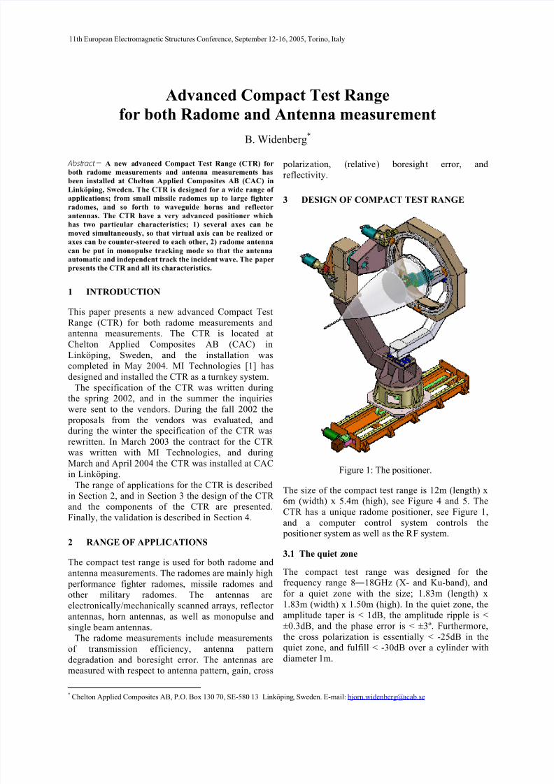
Figure 1: The positioner.
The size of the compact test range is 12m (length) x
6m (width) x 5.4m (high), see Figure 4 and 5. The
CTR has a unique radome positioner, see Figure 1,
and a computer control system controls the
positioner system as well as the RF system.
3.1 The quiet zone
The compact test range was designed for the
frequency range 8―18GHz (X- and Ku-band), and
for a quiet zone with the size; 1.83m (length) x
1.83m (width) x 1.50m (high). In the quiet zone, the
amplitude taper is < 1dB, the amplitude ripple is <
±0.3dB, and the phase error is < ±3º. Furthermore,
the cross polarization is essentially < -25dB in the
quiet zone, and fulfill < -30dB over a cylinder with
diameter 1m.
11th European Electromagnetic Structures Conference, September 12-16, 2005, Torino, Italy
7/21/2019 Advanced_compact_test_range for Both Radome and Antenna Measurement
http://slidepdf.com/reader/full/advancedcompacttestrange-for-both-radome-and-antenna-measurement 2/4
3.2 Reflector and Feed
The reflector is a standard reflector from MI
Technologies, denoted MI-5706 [1]. It is an offset
parabolic reflector with serrated edges, see Figure 4
and 5. The size of the reflector is 4.2m width and3.2m high, and the focal length is 3.6m. The
serrations follow the curvature of the reflector and
the size of the serrations is 0.6m.
The CTR has a floor mounted feed. The feed is
linearly polarized and the feed positioner has a
computer controlled roll axes for polarization of the
field in the quiet zone. Two feeds cover the
frequency band (X-band feed and Ku-band feed) and
the feeds are exchanged manually.
3.3 Positioner
At microwave measurements in the CTR, the deviceunder test (DUT, radome or antenna) is mounted on
a very advanced positioner with 7 computer
controlled axes, see Figure 1. There are 3 axes for
moving the radome, and the axis order is roll-over-
elevation-over-azimuth. On the antenna post is a
sophisticated gimbal mounted and the gimbal has 3
axes for moving the radome antenna with the axis
order elevation-over-azimuth-over-roll. The accuracy
for the gimbal axes and for the radome azimuth is
±0.005º, and the accuracy is ±0.05º for the other
axes. The remaining computer controlled axes is the
lower slide which can move the complete positioner
1.8m in down-range direction.Furthermore the radome antenna post can manually
be moved 0.2m in both down range and cross range
direction. The gimbal can also simply be exchanged
for other gimbals to fit particular radomes or radome
antennas.
For antenna measurements, the antenna under test
(AUT) is mounted either on the radome antenna post
or on the radome roll ring. If the AUT is mounted on
the roll ring the gimbal can be dismounted.
The positioner is constructed very robust because it
shall be able to carry radomes up to 150kg without
bending more than 0.1mRad.
3.4 Virtual axis and Counter-steering
Several computer controlled axes can be moved
simultaneously, so that virtual axis can be realized or
axes can be counter-steered to each other. It is a
necessity for transmission measurements, because
the radome antenna post is attached to the radome
azimuth. The counter-steering is applied in order to
keep the boresight of the radome antenna in the
down range direction.
3.5 Tracking
A very unique characteristic of this positioner and
this control system is that the radome antenna can be
put in monopulse tracking mode. This means that the
antenna automatically and independent tracks theincident wave and find the boresight. This is very
useful during boresight measurements, because then
the control system moves the radome, the radome
antenna automatically compensates for the boresight
error and this compensated angles are recorded by
the system.
3.6 Reflectometer
Another large quality of the CTR is that a
reflectormeter is integrated in the CTR so that the
reflection coefficient for the radome or antenna can
be measured while the DUT is mounted in the CTR.This reduce the handling of the DUT, and by placing
the reflectometer near the DUT, the measurement
uncertainty intrinsic to long cable runs can be
minimized. Details about the reflectometer can be
found in [2].
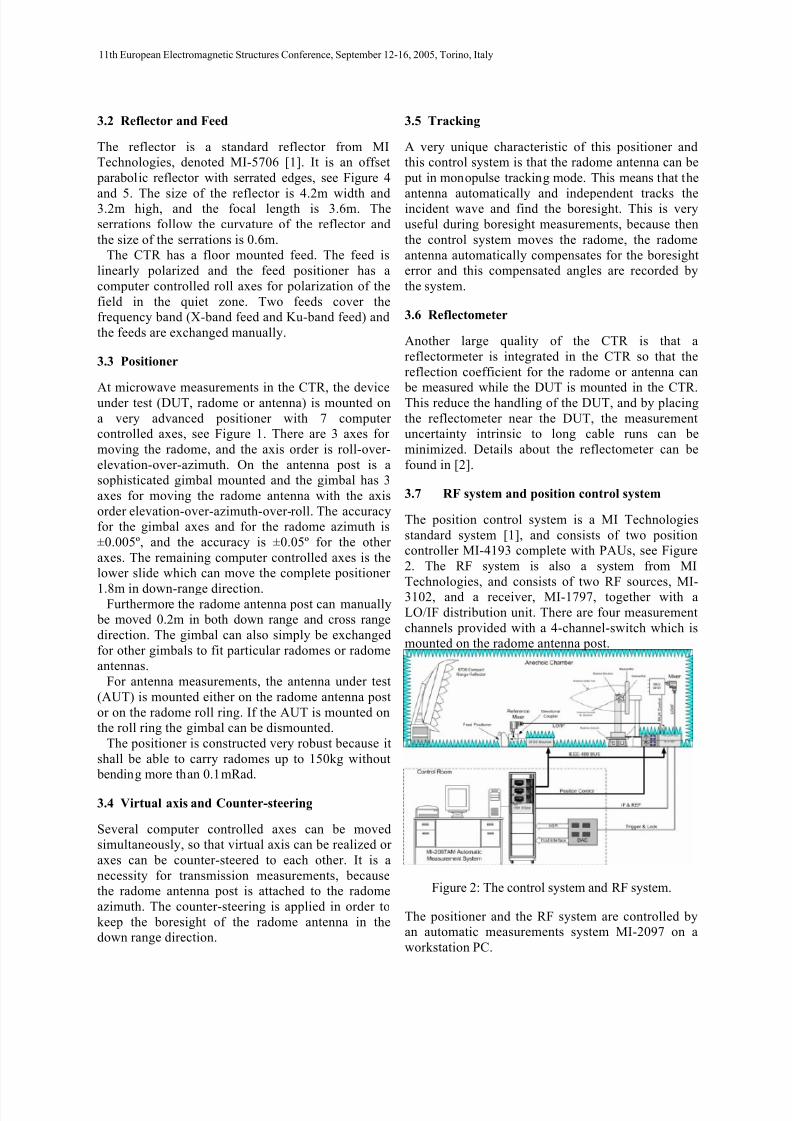
3.7 RF system and position control system
The position control system is a MI Technologies
standard system [1], and consists of two position
controller MI-4193 complete with PAUs, see Figure
2. The RF system is also a system from MI
Technologies, and consists of two RF sources, MI-
3102, and a receiver, MI-1797, together with a
LO/IF distribution unit. There are four measurement
channels provided with a 4-channel-switch which is
mounted on the radome antenna post.
Figure 2: The control system and RF system.
The positioner and the RF system are controlled by
an automatic measurements system MI-2097 on a
workstation PC.
11th European Electromagnetic Structures Conference, September 12-16, 2005, Torino, Italy
7/21/2019 Advanced_compact_test_range for Both Radome and Antenna Measurement
http://slidepdf.com/reader/full/advancedcompacttestrange-for-both-radome-and-antenna-measurement 3/4
4 VALIDATION
A range of measurements have been made in order to
assess the performance of the Compact Test Range.
They are divided into four main groups; 1) Positioner
Alignment, 2) Amplitude and Phase aperture scans,3) Reference Antenna Diagrams, 4) Reference
Radome Measurements,. The first two tests were
included in Acceptance Test Procedure, ATP, and
was performed by MI Technologies before and
during the installation. The other two tests were
performed by CAC after the installation. CAC did
also validate the dynamic range for the RF system
and check the performance of the tracking system.
4.1 Positioner Aligment (FAT)
The verification of the positioner, axes, alignment,
and accuracies was already completed by MITechnologies at time of installation of the test site.
This measurement set was carried out by MI
Technologies as part of the ATP but in the factory
before shipping to Chelton (Factory Acceptance
Test, FAT).
There were only 2 failures, and these two failures
were only marginal failures of the reverse limits for
the Antenna Roll and Azimuth axes.
4.2 Quiet zone scans (ATP)
The verification of the Quiet Zone, Co and Cross
polar, Amplitude and Phase Scans was completed byMI Technologies during time of installation of the
test site.
This measurement set was made using special quiet
zone scanning equipment which is not part of the
supplied test facility. It was therefore carried out by
MI Technologies as part of the ATP before the
antenna/radome elevation positioner was installed.
There are two sets of data – one set (the quiet zone)
fully analyzed by MI Technologies and a second set
not analyzed. This second set for the extended area
outside the specified quiet zone (2.4m x 2.4m) is for
get knowledge of the performance outside the quiet
zone.The main conclusions can be summarized as the
amplitude and phase scans generally meet the
requirement with the exception of the cross polar
component, which were a few dB to high for some
positions on edges in quiet zone.
4.3 Golden Antenna Measurements
The reference antenna measurements were
performed by CAC, and measurements were made
using high gain antennas at different slide positions.
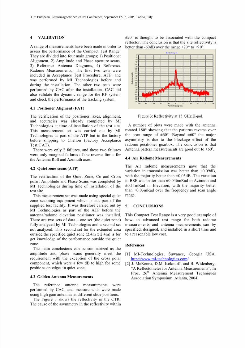
The Figure 3 shows the reflectivity in the CTR.
The cause of the asymmetry in the reflectivity within
±20o is thought to be associated with the compact
reflector. The conclusion is that the site reflectivity is
better than -60dB over the range ±20° to ±90°.
Reflectivity f4
Az imuth (Degr ees)
100806040200-20-40-60-80-100
R e f l e c t i v i t y ( d B )
0
-5
-10
-15
-20
-25
-30
-35
-40
-45
-50
-55
-60
-65
-70
-75
-80
-85
-90
-95
-100
Figure 3: Reflectivity at 15 GHz H-pol.
A number of plots were made with the antenna
rotated 180° showing that the patterns reverse over
the scan range of ±60°. Beyond ±60° the major
asymmetry is due to the blockage effect of the
radome positioner gearbox. The conclusion is that
Antenna pattern measurements are good out to ±60o.
4.4 Air Radome Measurements
The Air radome measurements gave that the
variation in transmission was better than ±0.09dB,
with the majority better than ±0.05dB. The variation
in BSE was better than ±0.046mRad in Azimuth and
±0.11mRad in Elevation, with the majority better
than ±0.03mRad over the frequency and scan angle
range.
5 CONCLUSIONS
This Compact Test Range is a very good example of
how an advanced test range for both radome
measurements and antenna measurements can by
specified, designed, and installed in a short time and
to a reasonable low cost.
References
[1] MI-Technologies, Suwanee, Georgia USA.
http://www.mi-technologies.com/.
[2] J. McKenna, D.M. Kokotoff, and B. Widenberg,
“A Reflectometer for Antenna Measurements”, In
Proc. 26th Antenna Measurement Techniques
Association Symposium, Atlanta, 2004.
11th European Electromagnetic Structures Conference, September 12-16, 2005, Torino, Italy

7/21/2019 Advanced_compact_test_range for Both Radome and Antenna Measurement
http://slidepdf.com/reader/full/advancedcompacttestrange-for-both-radome-and-antenna-measurement 4/4
Figure 4: Side view of the Compact Test Range.
Figure 5: Top view of the Compact Test Range.
11th European Electromagnetic Structures Conference, September 12-16, 2005, Torino, Italy