advancements in automotive antennas - intechopencdn.intechweb.org/pdfs/13369.pdf · advancements in...
TRANSCRIPT

26
Advancements in Automotive Antennas
Brendan D. Pell, Edin Sulic, Wayne S. T. Rowe, Kamran Ghorbani and Sabu John
RMIT University
Australia
1. Introduction
Today's production vehicles are fitted with a multitude of antennas to facilitate
communication and enable a moving vehicle to connect with the outside world. Recent
years have seen the introduction of new electronic devices to the automotive environment.
These devices are usually designed to aid the driver, increase safety, or enhance the driving
experience, and many of them rely on wireless communication to perform their task.
Antennas are a necessary part of any wireless communication system, enabling transmission
and reception of signals in free-space.
At the same time, automobile manufacturers have been seeking to create cost effective, fuel
efficient vehicles with attractive styling. This leads to a focus on sleek, lightweight vehicles
with reduced aerodynamic drag and improved styling - an emphasis that would naturally
conflict with fitment of traditional antennas. These market preferences, along with the
technological factors, have combined in the past few years to drive significant innovation in
the world of vehicular antennas.
In this chapter, we review the basics of antennas and radiation and examine the frequencies
and services which are commonly used in the automotive environment. We will briefly
discuss the antennas traditionally used on vehicles, and then detail the recent developments
and trends in automotive antenna research.
2. Antenna fundamentals
Antennas are necessary components of any wireless communications device or system. An
antenna is a device designed to send or receive radio waves. The antenna takes a guided
wave, usually bound to a transmission line of some type such as a coaxial line, waveguide
or microstrip transmission line and allows that same energy to propagate through free
space. Antennas are passive devices, meaning that they do not require an external power
source. They are also linear, meaning that their function is preserved regardless of the
applied power level, and reciprocal, which implies that they behave in an equivalent
manner in either transmit or receive modes.
Electrically conductive materials are commonly used to create antennas. Most antennas are
made from metals, although they can be constructed from dielectric materials.
www.intechopen.com
New Trends and Developments in Automotive System Engineering
514
2.1 Key properties of antennas Specialised terminology is used to describe antenna performance. This language allows
engineers to express antenna behaviour, specify requirements, and compare various design
options. Some of the most commonly used terms are included below. Text which appears
in quotation marks is from the IEEE Standard Definitions of Terms for Antennas (IEEE Std
145-1993).
Bandwidth
The bandwidth of an antenna refers to “the range of frequencies within which the
performance of the antenna, with respect to some characteristic, conforms to a specified
standard”. The most common usage of bandwidth is in the sense of impedance bandwidth,
which refers to those frequencies over which an antenna may operate. This is often defined
with the aid of the Voltage Standing Wave Ratio (VSWR) or return loss values from
measurements.
Other bandwidths which may be referred to are gain bandwidth, which defines the range of
frequencies over which the gain is above a certain value, and axial ratio bandwidth which may
be used in the case of a circularly polarised antenna.
Radiation Pattern
The radiation pattern represents the energy radiated from the antenna in each direction, often
pictorially. The IEEE Definition states that it is “the spatial distribution of a quantity that
characterizes the electromagnetic field generated by an antenna”. Most often this is the
radiation intensity or power radiated in a given direction.
Gain
In many wireless systems an antenna is designed to enhance radiation in one direction while
minimising radiation in other directions. This is achieved by increasing the directivity of the
antenna which leads to gain in a particular direction. The gain is thus “the ratio of the
radiation intensity, in a given direction, to the radiation intensity that would be obtained if
the power accepted by the antenna were radiated isotropically” (that is, equally in all
directions). In the case of a receiving antenna, an increase in gain produces increased
sensitivity to signals coming from one direction with the corollary of a degree of rejection to
signals coming from other directions. Antenna gain is often related to the gain of an
isotropic radiator, resulting in units dBi. An alternative is to relate the gain of any given
antenna to the gain of a dipole thus producing the units dBd. (0 dBd = 2.15 dBi). Antenna
gain may be viewed with the aid of a radiation pattern.
Polarisation
Polarisation of the wave radiated from an antenna describes the behaviour of the electric and
magnetic field vectors as they propagate through free space. Polarisation is typically
approximately linear. When linear the polarisation may be further described as either
vertical or horizontal based on the orientation of the electric field with respect to earth. In the
automotive environment, the polarisation of signals depends on the service in question.
Many satellite services (such as GPS) use circularly polarised signals. For best performance
the polarisation of the receive antenna should match the polarisation of the transmitted
signal.
www.intechopen.com
Advancements in Automotive Antennas
515
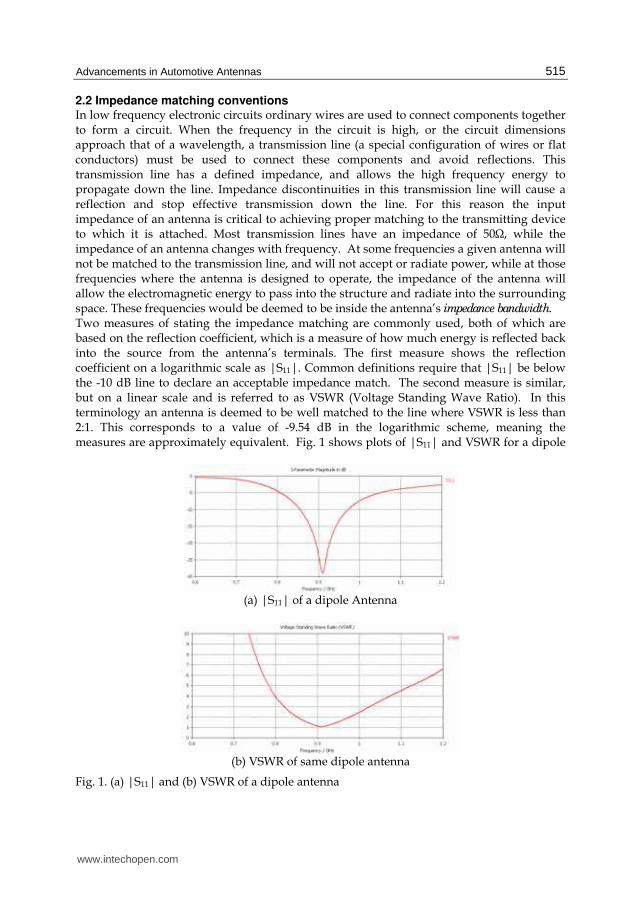
2.2 Impedance matching conventions In low frequency electronic circuits ordinary wires are used to connect components together to form a circuit. When the frequency in the circuit is high, or the circuit dimensions approach that of a wavelength, a transmission line (a special configuration of wires or flat conductors) must be used to connect these components and avoid reflections. This transmission line has a defined impedance, and allows the high frequency energy to propagate down the line. Impedance discontinuities in this transmission line will cause a reflection and stop effective transmission down the line. For this reason the input impedance of an antenna is critical to achieving proper matching to the transmitting device to which it is attached. Most transmission lines have an impedance of 50Ω, while the impedance of an antenna changes with frequency. At some frequencies a given antenna will not be matched to the transmission line, and will not accept or radiate power, while at those frequencies where the antenna is designed to operate, the impedance of the antenna will allow the electromagnetic energy to pass into the structure and radiate into the surrounding space. These frequencies would be deemed to be inside the antenna’s impedance bandwidth. Two measures of stating the impedance matching are commonly used, both of which are based on the reflection coefficient, which is a measure of how much energy is reflected back into the source from the antenna’s terminals. The first measure shows the reflection coefficient on a logarithmic scale as |S11|. Common definitions require that |S11| be below the -10 dB line to declare an acceptable impedance match. The second measure is similar, but on a linear scale and is referred to as VSWR (Voltage Standing Wave Ratio). In this terminology an antenna is deemed to be well matched to the line where VSWR is less than 2:1. This corresponds to a value of -9.54 dB in the logarithmic scheme, meaning the measures are approximately equivalent. Fig. 1 shows plots of |S11| and VSWR for a dipole
(a) |S11| of a dipole Antenna
(b) VSWR of same dipole antenna
Fig. 1. (a) |S11| and (b) VSWR of a dipole antenna
www.intechopen.com
New Trends and Developments in Automotive System Engineering
516
antenna which is resonant near 900 MHz. Although the shape of the curves is different due
to the use of either log or linear scaling, both plots reveal that the antenna presents a good
impedance match to frequencies in the range from approximately 850 MHz to 970 MHz.
Although a 10 dB return loss is typically required in the majority of antenna applications,
there are some exceptions. While some high performance systems may specify more precise
matching, a notable exception is the cellular phone industry which permits more relaxed
specifications. Most modern cellular phone antennas meet an |S11| requirement of
-6 dB (Waterhouse, 2008) which is equivalent to a VSWR of 3:1. Recent years of handset
design have led to a trade off which sacrifices antenna performance in order to obtain an
attractive small sized handset. The signal strengths used in cellular networks combined
with advances in receiver technology and modulation schemes compensate for handset
antennas having low radiation efficiency and poor electrical performance, resulting in
adequate performance of the overall system.
2.3 Radiation pattern essentials Gain and Radiation Pattern were introduced in Section 2.1. This section describes some
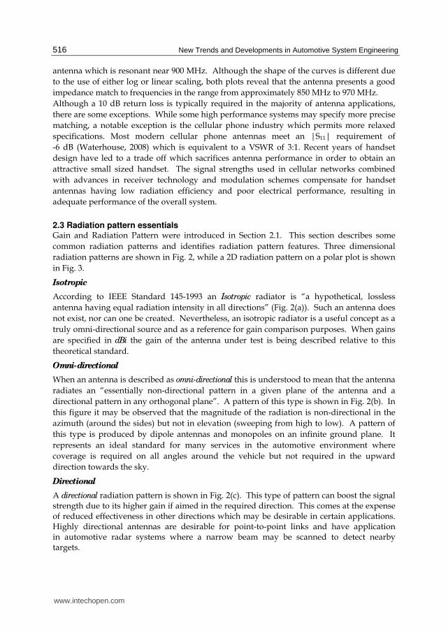
common radiation patterns and identifies radiation pattern features. Three dimensional
radiation patterns are shown in Fig. 2, while a 2D radiation pattern on a polar plot is shown
in Fig. 3.
Isotropic
According to IEEE Standard 145-1993 an Isotropic radiator is “a hypothetical, lossless
antenna having equal radiation intensity in all directions” (Fig. 2(a)). Such an antenna does
not exist, nor can one be created. Nevertheless, an isotropic radiator is a useful concept as a
truly omni-directional source and as a reference for gain comparison purposes. When gains
are specified in dBi the gain of the antenna under test is being described relative to this
theoretical standard.
Omni-directional
When an antenna is described as omni-directional this is understood to mean that the antenna
radiates an “essentially non-directional pattern in a given plane of the antenna and a
directional pattern in any orthogonal plane”. A pattern of this type is shown in Fig. 2(b). In
this figure it may be observed that the magnitude of the radiation is non-directional in the
azimuth (around the sides) but not in elevation (sweeping from high to low). A pattern of
this type is produced by dipole antennas and monopoles on an infinite ground plane. It
represents an ideal standard for many services in the automotive environment where
coverage is required on all angles around the vehicle but not required in the upward
direction towards the sky.
Directional
A directional radiation pattern is shown in Fig. 2(c). This type of pattern can boost the signal strength due to its higher gain if aimed in the required direction. This comes at the expense of reduced effectiveness in other directions which may be desirable in certain applications. Highly directional antennas are desirable for point-to-point links and have application in automotive radar systems where a narrow beam may be scanned to detect nearby targets.
www.intechopen.com
Advancements in Automotive Antennas
517
(a) Isotropic (b) Omni-directional (c) Directional
Fig. 2. Three dimensional radiation patterns
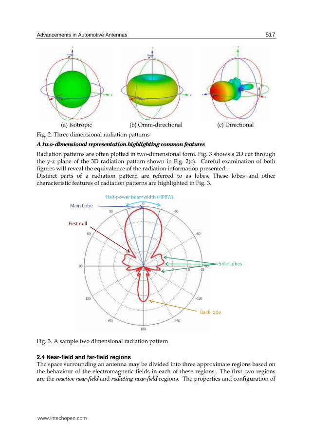
A two-dimensional representation highlighting common features
Radiation patterns are often plotted in two-dimensional form. Fig. 3 shows a 2D cut through the y-z plane of the 3D radiation pattern shown in Fig. 2(c). Careful examination of both figures will reveal the equivalence of the radiation information presented. Distinct parts of a radiation pattern are referred to as lobes. These lobes and other characteristic features of radiation patterns are highlighted in Fig. 3.
Main Lobe
Half-power beamwidth (HPBW)
Side Lobes
First null
Back lobe
Fig. 3. A sample two dimensional radiation pattern
2.4 Near-field and far-field regions The space surrounding an antenna may be divided into three approximate regions based on the behaviour of the electromagnetic fields in each of these regions. The first two regions are the reactive near-field and radiating near-field regions. The properties and configuration of
www.intechopen.com

New Trends and Developments in Automotive System Engineering
518
surrounding material in these regions may alter antenna performance, and the field at any angle is dependent on the distance to the antenna. In the third region known as the far-field
region however it can be assumed that the antenna is a point source. The far-field region is normally regarded as beginning when the distance to the antenna is equal to 2D2/λ, where D is the maximum overall dimension of the antenna and continues on to infinity. Once in the far-field region, the radiation pattern and gain may be measured.
2.5 System considerations Antennas are necessary components of all wireless systems, but are not of themselves sufficient for signal reception. Antennas do not operate in isolation. Here we briefly examine other important factors related to vehicular antenna systems.
Diversity Reception
Some automotive services use diversity to enhance the quality of the received signal. In non-line-of-site propagation environments such as the urban environment, reflections and shadows cast by buildings and other structures can cause fading in the signal strength in particular spatial locations or in given directions. In a diversity scheme two or more antennas are mounted in different locations or with different orientations on the vehicle. This provides two independent propagation paths for the signal. On an elementary level the diversity receiver switches between antennas to choose the one with the stronger signal. This provides a higher quality signal with fewer dropouts. Diversity is most commonly employed for FM radio reception purposes. Given that cars fitted with multiple antennas are regarded as being less visually appealing, vehicle manufacturers tend to combine an external mast antenna with a glass mounted antenna to give two distinct antennas for diversity purposes. This approach often achieves spatial and polarisation diversity, along with diversity in radiation direction.
Noise, Sensitivity and the Receiver
Any communications system receives the desired signal plus an unwanted signal which we may call noise. Noise comes from a variety of sources, ranging from the random movement of electrons inside any conductor (at a temperature above absolute zero) to Electromagnetic Interference (EMI) coupled in with the signal from nearby devices. In the automotive environment the vehicle’s ignition system can be a source of significant EMI, meaning that antennas mounted near the front of the vehicle may receive more noise than an equivalent antenna mounted towards the rear. Receiving systems have a specified sensitivity, which relates the minimum signal strength at
the input required to achieve an acceptable Signal-to-Noise ratio (SNR). The sensitivity of
commercial automotive receiving systems will have a large impact on the overall quality of
the received service, particularly in areas of low signal strength.
In car radio systems the receiver may be called a tuner since it tunes its internal oscillators to demodulate the required station. The input impedance of the tuner, along with other fundamental properties are important in ensuring proper system operation.
3. Automotive frequencies and wireless services
In previous decades the use of antennas in vehicles was primarily limited to those employed for AM and FM radio. In contrast, today's vehicles are often fitted with many antennas for
www.intechopen.com
Advancements in Automotive Antennas
519
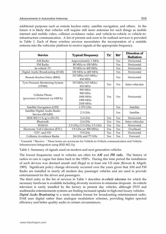
additional purposes such as remote keyless entry, satellite navigation, and others. In the future it is likely that vehicles will require still more antennas for such things as mobile internet and mobile video, collision avoidance radar, and vehicle-to-vehicle or vehicle-to-infrastructure communication. A list of present and soon to be realised services is provided in Table 1. Each of these wireless services necessitates the incorporation of a suitable antenna into the vehicular platform to receive signals at the appropriate frequency.
Service Typical Frequency Tx* Rx#Direction of
Radiation
AM Radio Approximately 1 MHz Yes Horizontal
FM Radio 88 MHz to 108 MHz Yes Horizontal
In-vehicle TV 50 MHz to 400 MHz Yes Horizontal
Digital Audio Broadcasting (DAB) 100 MHz to 400 MHz Yes Horizontal
Remote Keyless Entry (RKE) 315 MHz/413 MHz/
434 MHz Yes Horizontal
Tyre Pressure Monitoring System (TPMS)
315 MHz/413 MHz/ 434 MHz
Yes Yes Intra-vehicular
Cellular Phone (provision of Internet via HSPA)
850 MHz 900 MHz 1800 MHz 1900 MHz 2100 MHz
Yes Yes Horizontal
Satellite Navigation (GPS) 1.575 GHz Yes Satellite
Satellite Digital Audio Radio Service (SDARS)
2.3 GHz Yes Satellite
IEEE 802.11 b/g/n (Wi-Fi) 2.4 GHz Yes Yes Horizontal
Bluetooth 2.4 GHz Yes Yes Intra-vehicular
WiMAX 2.3 GHz/2.5 GHz/3.5 GHz Yes Yes Horizontal
Electronic Toll Collection (ETC) 5.8 GHz (or 900 MHz) Yes Yes Overhead
V2V+ and VII+ 5.9 GHz Yes Yes Horizontal
Collision Avoidance Radar 24 GHz and 77 GHz Yes Yes Forward
* Transmit # Receive + These terms are acronyms for Vehicle-to-Vehicle communication and Vehicle-Infrastructure-Integration using IEEE 802.11p
Table 1. Summary of signals used on modern and next generation vehicles
The lowest frequencies used in vehicles are often for AM and FM radio. The history of
radios in cars is vague but dates back to the 1920’s. During this time period the installation
of such devices was deemed unsafe and illegal in at least one US state (Rowan & Altgelt,
1985). Significant policy change obviously occurred over the years given that AM and FM
Radio are installed in nearly all modern day passenger vehicles and are used to provide
entertainment for the driver and passengers.
The third entry in the list of services in Table 1 describes in-vehicle television for which the necessary hardware is available including diversity receivers to minimise dropouts. In-vehicle television is rarely installed by the factory in present day vehicles, although DVD and multimedia entertainments systems are finding increased uptake in high-end luxury vehicles. Digital Audio Broadcasting is a more modern format for broadcasting entertainment radio. DAB uses digital rather than analogue modulation schemes, providing higher spectral efficiency and better quality audio in certain circumstances.
www.intechopen.com

New Trends and Developments in Automotive System Engineering
520
Many present day vehicles are able to be locked and unlocked by pressing a button on a radio transmitter integrated into the car’s key or key ring. These services are known as Remote Keyless Entry, and typically operate in one of the low power bands shown in the table. These bands are often shared with Tyre Pressure Monitoring Systems which are finding increased acceptance in the passenger vehicle market and are available as third-party accessories. A typical TPMS has an air pressure sensor and wireless transmitter fitted to each wheel with a receiver unit mounted in or on the dash. The system can alert the driver to low tyre pressure before a flat tyre becomes a safety hazard. Many frequency bands are used globally for cellular telephone (a.k.a. mobile telephone). Blocks of new spectrum are occasionally released by the authorities and purchased by telecommunications companies to cater for increased demand. The most commonly used frequencies are provided in the table. Inclusion of these frequency bands into a vehicle could allow for voice calls and additionally a full suite of services based on high speed access to the internet provided by HSPA (High Speed Packet Access). This has the potential to bring about a realisation of useful Location Based Services, XML based traffic updates and internet connectivity almost anywhere in urban and rural environments. Guidance and navigation facilities are becoming more cost effective and seeing large uptake in the modern market. These navigation systems usually rely on the constellation of approximately thirty Global Positioning System (GPS) satellites to determine the location of the vehicle before plotting it on a map. The GPS L1 band is received in a narrow 20 MHz channel centred at 1.575 GHz. The Satellite Digital Audio Radio Service is also described in the table. This service delivers hundreds of additional radio stations and is implemented by using circularly polarised signals from satellites arranged in an orbit which dwells over the North American continent. In urban environments where buildings can cause multipath and shadowing of the satellites, terrestrial based transmitters are also used. The 2.4 GHz ISM band has seen enormous growth in the past decade due to the ubiquitous
application and implementation of Wi-Fi and Bluetooth which occupy part of this band.
Bluetooth is incorporated into many present day vehicles to allow hands free calling and
operation of an equipped mobile through the vehicle’s multimedia system. Future vehicles
may be fitted with Wi-Fi to enable passengers to access the internet while on a journey.
An emerging technology that will need to compete with LTE and HSPA technologies is
WiMAX. In a manner similar to the 3G and 4G cellular wireless standards, WiMAX could
be used to provide a high speed wireless internet connection to a moving vehicle many
kilometres from a base station.
Many Electronic Toll Collection systems are implemented at 5.8 GHz, often achieved by
windscreen mounted removable wireless tags operating in an active-RFID system.
Vehicle-to-Vehicle communication systems are currently being developed and trialled to enable
safer and more efficient road transport. A portion of spectrum at 5.9 GHz has been reserved
in many countries for this purpose, where vehicles and road side objects would form
networks and share safety information as part of an Intelligent Transportation System (ITS).
As an example a system such as this would alert the driver to sudden braking in traffic
ahead, and of upcoming lane closures or unexpected obstructions. Emergency vehicles
could broadcast warnings to drivers up to 1km away, signalling their presence and
intentions. Many phrases have been coined to describe this technology including Dedicated
Short Range Communications (DSRC), Vehicle2Vehicle (V2V), and Vehicle-Infrastructure-
www.intechopen.com
Advancements in Automotive Antennas
521
Integration (VII). The relevant IEEE standard upon which the wireless connection is based is
IEEE 802.11p. The US Department of Transport is developing these technologies in the
IntellidriveSM program.
Collision Avoidance Radar is a technology which integrates with the Adaptive Cruise Control
(ACC) system of a vehicle to prevent accidents, or in the case where a collision is
unavoidable, reduce the severity of the impact. In normal use the system uses RADAR (or
optionally LIDAR) to scan the road ahead and will reduce the throttle and apply brakes to
automatically maintain a safe buffer distance to the car in front. Some systems will also
detect pedestrians or other objects. In the event that the system detects an imminent
collision, it may apply emergency braking and other precautionary measures to increase
vehicle safety. Collision Avoidance Radar uses very high frequencies for numerous reasons
including spectrum availability, the small size of antenna elements enabling integration of
necessary phased array radar antennas, and the fact that a higher frequency helps to
increase the Radar Cross Section, and therefore, the detection range of targets of interest,
such as pedestrians and other vehicles.
4. Traditional AM/FM antennas
4.1 Mast antennas The low frequency and relatively high signal strengths encountered in AM and FM car radio
systems have allowed the use of uncomplicated antenna systems in the past. The most
common antenna traditionally used for these bands is the mast antenna. A conductive rod is
used to form a monopole antenna, approximately one quarter wavelength (λ/4) in length,
which equates to approximately 75 cm in the middle of the FM band. Locating such an
antenna in the centre of the roof gives the best radiation performance, with the antenna
elevated above obstructions and surrounded by a conducting ground plane of
approximately equal extent in all directions. Despite this, the front or rear fender is usually
preferred for aesthetic reasons. Retractable and non-retractable versions are commercially
available.
Antennas for receiving FM radio in vehicles should receive signals equally well from all
directions around the horizon, due to the movement and rotation of the vehicle with respect
to the transmitting source. This quarter wavelength monopole antenna would provide an
ideal radiation pattern in the azimuth if it was mounted above an infinite ground plane.
Typical fender mounting provides a very non-ideal ground plane however, leading to
radiation patterns that are less omni-directional (ie. the radiation becomes directional).
Hence, designing such antennas for vehicles has traditionally been an iterative process
involving several stages of prototyping and measurement on completed vehicle bodies.
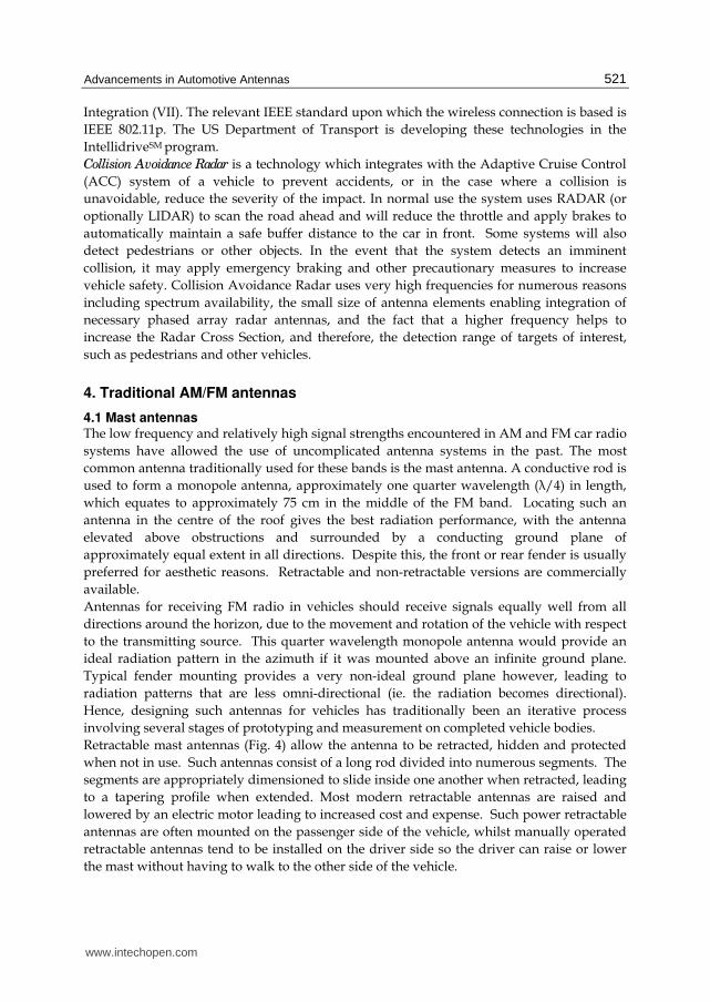
Retractable mast antennas (Fig. 4) allow the antenna to be retracted, hidden and protected
when not in use. Such antennas consist of a long rod divided into numerous segments. The
segments are appropriately dimensioned to slide inside one another when retracted, leading
to a tapering profile when extended. Most modern retractable antennas are raised and
lowered by an electric motor leading to increased cost and expense. Such power retractable
antennas are often mounted on the passenger side of the vehicle, whilst manually operated
retractable antennas tend to be installed on the driver side so the driver can raise or lower
the mast without having to walk to the other side of the vehicle.
www.intechopen.com
New Trends and Developments in Automotive System Engineering
522
(a) Manually retractable mast antenna (b) Power retractable mast antenna
Fig. 4. Technical drawings of typical mast antennas
4.2 Glass mounted AM/FM Antennas A second kind of AM and FM antenna is the glass mounted antenna. AM and FM antennas
using this technique have became very common in the last decade, as pre-amplifiers have
helped to compensate for poor radiation performance. On modern vehicles, these antennas
are similar in appearance to the demister elements commonly embedded in the rear
windscreen.
Many glass mounted antennas installed in present day vehicles are based on wire geometry
although the antenna may or may not be an actual wire. It can be formed by using wire of a
very thin diameter or a silk screened film which is laminated between layers of glass in the
vehicle windows (Jensen, 1971). Glass mounted antennas provide no additional
aerodynamic drag and create no wind noise which is a significant advantage over mast type
designs. They also require no holes to be created in the vehicle body, which may lead to
cheaper tooling for the metal work. Despite this, on glass antennas tend to be more
directional than mast antennas, which can lead to nulls in the reception on certain angles
around the vehicle.
On-glass antennas where first located in the rear windscreen, and this remains a common
position on sedans made today. Many SUV’s or station wagons use the rear quarter window
in preference to the rear window. A variety of different shapes are used for the antennas,
often forming grid or meandering geometries, with a shape that works well on one vehicle
not necessarily performing well on other vehicles (Gottwald, 1998). No universal glass
mounted antenna has yet been discovered. This is due to the effect of the vehicle body on
the antenna’s impedance and radiation, which is significant for on-glass antennas. Antenna
oriented vertically may provide better reception of vertically polarised signals.
Fig. 5 shows a typical active rear window antenna. Early designs adopted the defogger
elements themselves and connected through a DC blocking capacitor to the radio tuner.
Newer designs often separate these two functions, having a defogger element which
occupies most of the glass, with a smaller area set aside for antenna lines.
www.intechopen.com

Advancements in Automotive Antennas
523
Fig. 5. Schematic of a typical rear windscreen glass antenna.
5. New developments and research outcomes
Examination of production vehicles produced over the past ten to fifteen years reveals a shift away from the traditional quarter wavelength mast antenna towards more aesthetically pleasing antennas. This section provides a review of new findings and innovative solutions to vehicular antenna problems along with the advantages and disadvantages of each type.
5.1 Bee-sting antennas The bee-sting antenna is a wire antenna similar to the mast antenna used for many decades, but consists of a shortened element installed in a raked back attitude (Fig. 6). An amplifier is used to boost the signal level to compensate for the poor performance obtained by the shorter antenna length (Cerretelli & Biffi Gentili, 2007). Some antennas also include a separate feed for a Cellular phone or DAB system.
Fig. 6. Bee sting antenna © IEEE with permission (Cerretelli & Biffi Gentili, 2007)
5.2 Blade or Shark-fin antennas Many varieties of shark-fin antennas exist, having been popularised primarily by the European marques near the turn of the 21st century. Shark-fin antennas are commonly a collection of several antennas. Most designs consist of multiple narrowband antennas all located together under a single radome or housing. This housing is typically shaped like a blade or dorsal fin, and is usually located on the roof towards the rear of the vehicle. Two examples of shark-fin designs are shown in Fig. 7.
Coaxial
Cable
www.intechopen.com

New Trends and Developments in Automotive System Engineering
524
(a) (b)
Fig. 7. Shark-fin Antennas
Fig. 8 shows an early shark-fin antenna design in detail. This design was fitted to the BMW 3-Series (E46) and provides for cellular phone frequencies. The antenna consists of a cast steel base and a fin-shaped cover made from an ABS and Polycarbonate polymer. Radiating elements are on both sides of an FR-4 circuit board which stands erect in the middle of the device. Rubber gaskets are used to seal the inner components from the environment. The design achieves an impedance match (shown in Fig. 9) at the required frequencies by incorporating inline filters which allow the radiators to be a quarter wavelength long at high
(a) Shark-fin on vehicle roof (b) Shark-fin with radome removed showing
filters
Fig. 8. BMW 3-Series E46 Sharkfin Antenna
Fig. 9. Measured reflection coefficient of BMW 3-series E46 Shark-fin Antenna
www.intechopen.com

Advancements in Automotive Antennas
525
and low frequencies simultaneously. A surface mount resistor is used in conjunction with a printed inductor on the reverse side of the board to form a filter. This filter has the effect of connecting the upper radiating elements at lower frequencies by creating an electrical short circuit. At higher frequencies the filter creates an open circuit, leaving only the short elements connected to the feed line. Fig. 10 shows a shark-fin style antenna which was published in the literature for use in US automobiles (J.F. Hopf et al., 2007). With the cover removed, it is clear that this antenna demonstrates the case where multiple individual antennas are located together under a single radome. The leftmost antenna in the figure is a GPS antenna, constructed using a probe fed patch design on a high dielectric constant substrate. This provides a hemispherical radiation pattern covering the sky which is appropriate for receiving satellite signals. Circular polarisation may be induced in patch antennas such as these by truncating diagonally opposite corners of the patch, or by feeding the antenna off centre. The white antenna to the right of centre in the figure is a crossed frame antenna for SDARS reception. The two posts present in the design provide for cellular telephone reception. The elements are based on quarter wavelength monopoles with top loading elements to increase the effective electrical length at the low end of the band. The presence of these posts is typical of shark-fin antennas, however these particular posts contain filters which have been optimized to have minimal effect on the nearby SDARS antenna.
Fig. 10. Internals of a modern shark-fin antenna © IEEE with permission (J.F. Hopf et al., 2007)
5.3 TV antennas on glass Research has continued into traditional AM and FM antennas mounted on glass even today (Bogdanov et al., 2010), particularly in the area of effective simulation techniques. At the same time, antenna configurations for other services have also been investigated. An early paper describes the system shown in Fig. 11 of a diversity reception system for analogue TV. The antennas are printed on the rear quarter glass and have four branches. The antennas are arranged symmetrically on the left and right sides of the vehicle. The design includes some meandering elements which give a long electrical length in a small space. Other branches of the design include slanted and short horizontal elements. The authors claim the system provides improved performance over a rod antenna, and is capable of operating in the range from 90 MHz to 770 MHz (Toriyama et al., 1987).
www.intechopen.com

New Trends and Developments in Automotive System Engineering
526
Fig. 11. Analogue TV Antenna system in rear quarter glass © IEEE with permission (Toriyama et al., 1987)
A glass mounted antenna designed for the newer Digital Terrestrial TV reception is shown in Fig. 12. The H-shaped elements allow both long and short current paths to be formed, providing a wideband impedance match (Iizuka et al., 2005). The long path occurs when current flows diagonally from top left to bottom right in Fig. 12(a), while the shorter path runs diagonally from bottom left to top right. The impedance matching of this design results in a VSWR of less than 3:1 from 470 MHz to 710 MHz when connected to a 110Ω line. The antenna is formed on a low cost FR-4 substrate, and is integrated with an RF circuit which provides a balun, some filtering, and a Low Noise Amplifier (LNA) to boost the signal before it is sent down the transmission line to the tuner. Four of these antennas were installed in the test vehicle shown in Fig. 12(b), being located in the upper portion of both the front and rear windscreen on both driver and passenger sides. The gain and radiation pattern of the system was measured at 530 MHz, and it was found that the radiation pattern was nearly omni-directional at this frequency when all four antennas were excited.
Fig. 12. Digital TV Antenna attached to vehicle glass © IEEE with permission (Iizuka et al., 2005)
www.intechopen.com

Advancements in Automotive Antennas
527
5.4 Circular microstrip patch antenna on glass Microstrip Patch antennas have many advantages in communication systems including being thin, cheap to produce, and easy to integrate into devices. The application of this kind of antenna to automotive glass has been investigated by several researchers. One paper suggested two methods of patch antenna integration (Economou & Langley, 1998). The first is a patch antenna formed on a traditional microwave substrate such as Rogers RT Duroid® which is then attached to the inside of a vehicle windscreen (Fig. 13(a)). The second describes a more integrated concept which uses a layer of glass itself as the antenna substrate, and excites the patch with a proximity coupled feed line (Fig. 13(b)). Patch antennas using the first method of integration were designed to resonate near 2 GHz and 6 GHz respectively, and were adhered to a vehicle windscreen for testing. A useful increase in impedance bandwidth from less than 2% to about 7% was observed due to the addition of a thick dielectric superstrate. Presence of the glass also generates surface waves which create undesirable ripples in the far-field radiation pattern. The second method using glass as the antenna substrate poses fabrication complexities, and would lead to a high windscreen replacement cost in the event of cracking or breakage, so was only investigated by simulation. Simulation results showed that this geometry would also result in lower radiation efficiency due to increased surface wave losses. The electrical properties of the layers in the windscreen were ┝r1 = 6.75, tan ├ = 0.03 for the glass and ┝r2 = 2.9, tan ├ = 0.05 for the middle plastic layer. The thickness of automotive glass may vary by up to 15% in the standard manufacturing process. This causes no problems or distortions for driver vision, but could present a problem for patch antennas attached to glass. The centre frequency of the antenna may be shifted by up to 3% and could be coupled with an additional but slight change in the impedance bandwidth.
Fig. 13. Patch Antennas on glass © IEEE with permission (Economou & Langley, 1998)
5.5 Rear spoiler with built-in antenna In the late 1990’s a team of Japanese engineers working with Toyota and Aisin Seiki developed a rear spoiler to be mounted up high on the rear of a compact SUV. This spoiler was the first to be fitted with an invisible antenna (Fig. 14). The paper describes a blow molded part made from a polymeric material (Koike et al., 1999). The spoiler is located high
(a)
(b)
www.intechopen.com

New Trends and Developments in Automotive System Engineering
528
on the vehicle, minimizing shadowing from passing traffic. The antenna is similar to a dipole which would normally require a balanced feed. In order to connect a dipole antenna to a coaxial line, a balun is usually required. The geometry of the spoiler and processing temperature during manufacture would make integration of such a balun difficult. In order to overcome this, an innovative antenna design is used. The shorter element in Fig. 14(a) is approximately λ/4 long, while the longer element is approximately λ/2. Parametric investigations found that a tab at the end of the longer radiating element improved antenna performance by coupling to the vehicle’s metallic roof. Although the directivity is less than perfect (Fig. 14(b)), it is adequate for the intended application.
(a) (b)
Fig. 14. Integrated antenna in spoiler © SAE International with permission (Koike et al., 1999)
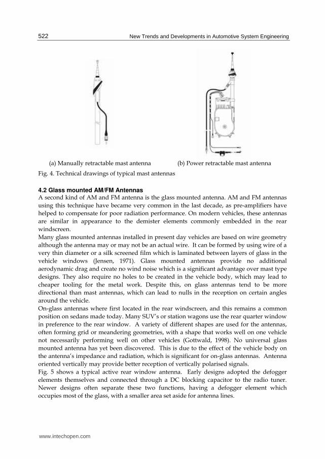
5.6 Volvo XC90 aperture antenna Swedish manufacturer Volvo fitted a unique antenna to their XC90 SUV, launched in 2003.
The system provides an alternative to glass mounted wire antennas which may be adversely
affected by heated windscreen elements and window tinting films containing conductive
metallic layers. The XC90 is fitted with a traditional metallic skinned “turret top” roof, but
an aperture is created at the rear of the vehicle. This opening is covered with a polymeric
panel, and forms an ideal location for some hidden antennas (Low et al., 2006). Fig. 15(a)
shows the XC90 from above and Fig. 15(b) shows some simulation results of the vehicle’s
metallic structure for different antenna configurations. The aperture in the vehicle body is
clearly shown. The portion of roof which contains the antennas is the black unpainted
section at the rear of the vehicle in Fig. 15(a) which at first glance may look like a sunroof.
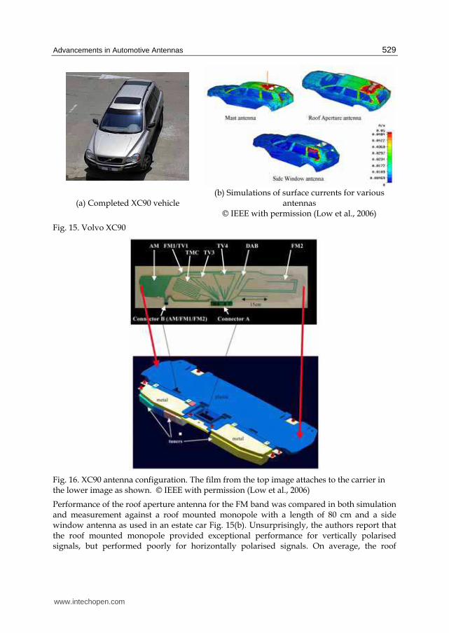
Seven antenna components (Fig. 16) are formed by printing wire shapes onto a large
polyester film using conductive ink. The antennas act as monopole probes, exciting the
aperture in which they are placed. For some services, multiple antennas are used in different
locations to achieve radiation and polarisation differences between elements allowing
diversity reception. The film bearing the printed antennas is attached to a plastic carrier
which contains the necessary amplifiers, and the whole unit is located in the aperture and
covered with a black polymeric composite material. Examination of Fig. 16 reveals that
these antennas are for low frequency services, with Table 1 revealing each service is centred
well below 1 GHz. This low frequency implies a long wavelength which requires physically
long antenna elements. Note that the services targeted in this design are different from
those commonly used in the smaller shark-fin style antennas.
www.intechopen.com
Advancements in Automotive Antennas
529
(a) Completed XC90 vehicle (b) Simulations of surface currents for various
antennas © IEEE with permission (Low et al., 2006)
Fig. 15. Volvo XC90
Fig. 16. XC90 antenna configuration. The film from the top image attaches to the carrier in the lower image as shown. © IEEE with permission (Low et al., 2006)
Performance of the roof aperture antenna for the FM band was compared in both simulation and measurement against a roof mounted monopole with a length of 80 cm and a side window antenna as used in an estate car Fig. 15(b). Unsurprisingly, the authors report that the roof mounted monopole provided exceptional performance for vertically polarised signals, but performed poorly for horizontally polarised signals. On average, the roof
www.intechopen.com
New Trends and Developments in Automotive System Engineering
530
mounted aperture antenna performed approximately 2 dB better than the side window antenna, but was unable to trump the roof mounted monopole for vertical polarisation gain.
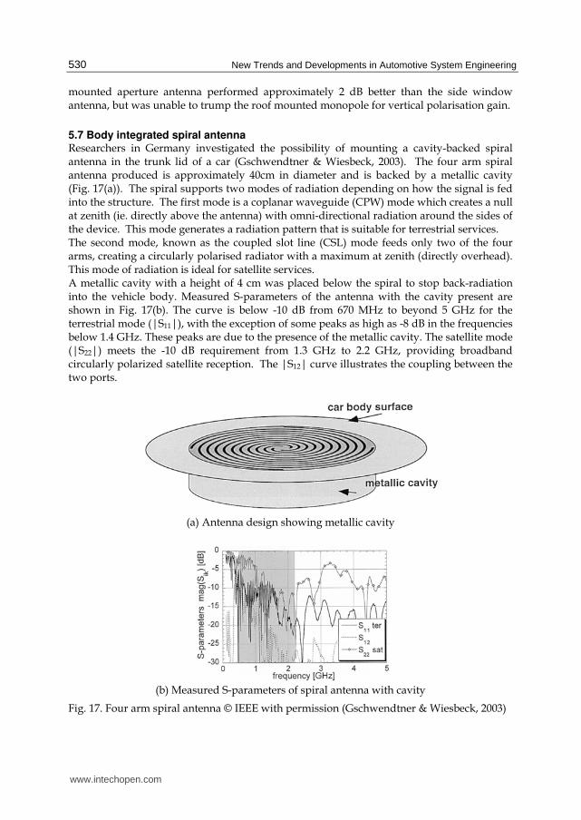
5.7 Body integrated spiral antenna Researchers in Germany investigated the possibility of mounting a cavity-backed spiral antenna in the trunk lid of a car (Gschwendtner & Wiesbeck, 2003). The four arm spiral antenna produced is approximately 40cm in diameter and is backed by a metallic cavity (Fig. 17(a)). The spiral supports two modes of radiation depending on how the signal is fed into the structure. The first mode is a coplanar waveguide (CPW) mode which creates a null at zenith (ie. directly above the antenna) with omni-directional radiation around the sides of the device. This mode generates a radiation pattern that is suitable for terrestrial services. The second mode, known as the coupled slot line (CSL) mode feeds only two of the four arms, creating a circularly polarised radiator with a maximum at zenith (directly overhead). This mode of radiation is ideal for satellite services. A metallic cavity with a height of 4 cm was placed below the spiral to stop back-radiation into the vehicle body. Measured S-parameters of the antenna with the cavity present are shown in Fig. 17(b). The curve is below -10 dB from 670 MHz to beyond 5 GHz for the terrestrial mode (|S11|), with the exception of some peaks as high as -8 dB in the frequencies below 1.4 GHz. These peaks are due to the presence of the metallic cavity. The satellite mode (|S22|) meets the -10 dB requirement from 1.3 GHz to 2.2 GHz, providing broadband circularly polarized satellite reception. The |S12| curve illustrates the coupling between the two ports.
(a) Antenna design showing metallic cavity
(b) Measured S-parameters of spiral antenna with cavity
Fig. 17. Four arm spiral antenna © IEEE with permission (Gschwendtner & Wiesbeck, 2003)
www.intechopen.com
Advancements in Automotive Antennas
531
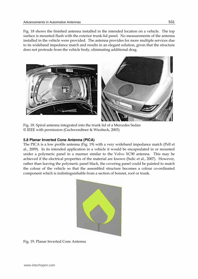
Fig. 18 shows the finished antenna installed in the intended location on a vehicle. The top surface is mounted flush with the exterior trunk-lid panel. No measurements of the antenna installed in the vehicle were provided. The antenna provides for more multiple services due to its wideband impedance match and results in an elegant solution, given that the structure does not protrude from the vehicle body, eliminating additional drag.
Fig. 18. Spiral antenna integrated into the trunk lid of a Mercedes Sedan © IEEE with permission (Gschwendtner & Wiesbeck, 2003)
5.8 Planar Inverted Cone Antenna (PICA) The PICA is a low profile antenna (Fig. 19) with a very wideband impedance match (Pell et
al., 2009). In its intended application in a vehicle it would be encapsulated in or mounted
under a polymeric panel in a manner similar to the Volvo XC90 antenna. This may be
achieved if the electrical properties of the material are known (Sulic et al., 2007). However,
rather than leaving the polymeric panel black, the covering panel could be painted to match
the colour of the vehicle so that the assembled structure becomes a colour co-ordinated
component which is indistinguishable from a section of bonnet, roof or trunk.
Fig. 19. Planar Inverted Cone Antenna
www.intechopen.com

New Trends and Developments in Automotive System Engineering
532
The use of a wideband antenna is similar in concept to that used by Gschwendtner and Wiesbeck in the previously examined spiral antenna. Due to its wide impedance bandwidth, a single antenna can cover more than one service if appropriate interfacing hardware is provided. In contrast to the cavity-backed spiral antenna, the PICA provides a wider impedance bandwidth and is fabricated on industry standard circuit board material (FR-4), making series production affordable. It requires no cavity, giving a thinner overall structure, and may be attached to the underside of surfaces which feature a gentle curve, making it a truly conformal solution. Being fabricated on a square 20 cm x 20 cm substrate, the enlarged uniplanar CPW-fed PICA provides a suitable antenna for many of the services in Table 1. It presents a good impedance match to a 50 ohm line over a wide range of frequencies extending from 730 MHz to beyond 10 GHz (Fig. 20).
Fig. 20. Simulated impedance response of the Large PICA antenna
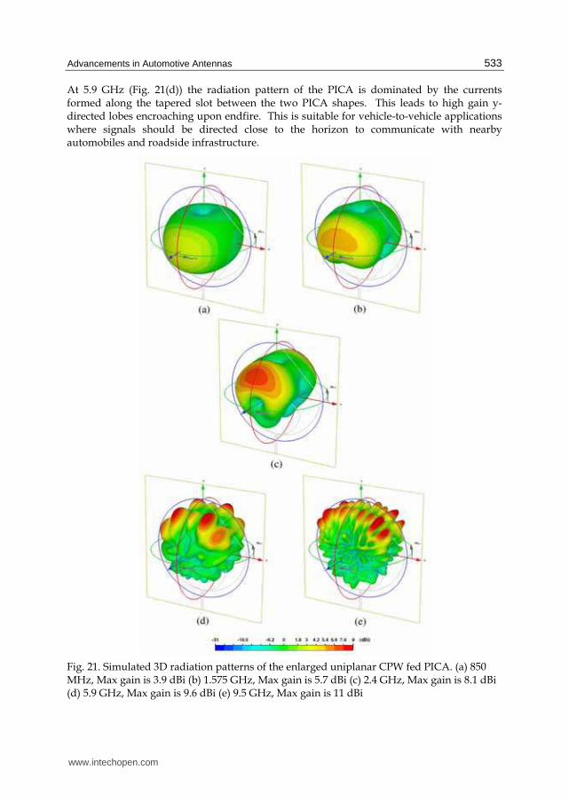
In the case where an antenna such as the PICA may be encapsulated in the middle of a dielectric material, it may experience deformation due to the pressure and flow of material during the moulding process. This requires a thorough understanding of the rheology of the material to be used (Sulic et al., 2010). An understanding of the properties of the polymer may influence the temperature at which the material is cured during manufacturing, and will impact on the way the charge is loaded into the tool in preparation for moulding. The radiation pattern of the antenna in free space changes across the frequency band in a manner convenient for the application. At each frequency the level of gain in the required direction is suitable for vehicular use when mounted in a horizontal attitude, as would be the case in a bonnet, roof or trunk lid. Fig. 21 shows the simulated radiation pattern of the antenna at key frequencies in the band. Where possible, these frequencies were selected to align with an automotive service. At cellular phone frequencies (Fig. 21(a)) the pattern is wide with low directivity. The peak gain occurs at broadside to the antenna substrate, yet in the plane of the substrate (x-y plane) the gain averages about 0 dBi with a null in the y direction. Given that cellular phone towers are terrestrially based, it is this horizontal part of the radiation pattern which is critical, and the gain is adequate. Fig. 21(b) shows the radiation pattern at the frequency used for GPS. The radiation pattern has become slightly more directed, with a realised gain of 5.7 dBi. Despite the lack of circular polarisation, the radiation performance of the PICA should provide a satisfactory signal to a modern receiver unit like the SiRFStarIII™ to enable accurate positioning. Verification of this assumption is a matter of present investigation.
www.intechopen.com
Advancements in Automotive Antennas
533
At 5.9 GHz (Fig. 21(d)) the radiation pattern of the PICA is dominated by the currents formed along the tapered slot between the two PICA shapes. This leads to high gain y-directed lobes encroaching upon endfire. This is suitable for vehicle-to-vehicle applications where signals should be directed close to the horizon to communicate with nearby automobiles and roadside infrastructure.
Fig. 21. Simulated 3D radiation patterns of the enlarged uniplanar CPW fed PICA. (a) 850 MHz, Max gain is 3.9 dBi (b) 1.575 GHz, Max gain is 5.7 dBi (c) 2.4 GHz, Max gain is 8.1 dBi (d) 5.9 GHz, Max gain is 9.6 dBi (e) 9.5 GHz, Max gain is 11 dBi
www.intechopen.com
New Trends and Developments in Automotive System Engineering
534
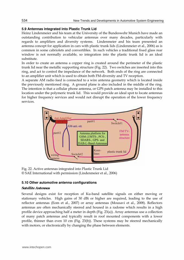
5.9 Antennas integrated into Plastic Trunk Lid Heinz Lindenmeier and his team at the University of the Bundeswehr Munich have made an outstanding contribution to vehicular antennas over many decades, particularly with regards to amplifiers and diversity systems. Lindenmeier and his team presented an antenna concept for application in cars with plastic trunk lids (Lindenmeier et al., 2006) as is common in some cabriolets and convertibles. In such vehicles a traditional fixed glass rear window is not normally available, so integration into the plastic trunk lid is an ideal substitute. In order to create an antenna a copper ring is created around the perimeter of the plastic trunk lid near the metallic supporting structure (Fig. 22). Two switches are inserted into this ring, and act to control the impedance of the network. Both ends of the ring are connected to an amplifier unit which is used to obtain both FM-diversity and TV reception. A separate AM radio feed is connected to a wire antenna geometry which is located inside the previously mentioned ring. A ground plane is also included in the middle of the ring. The intention is that a cellular phone antenna, or GPS patch antenna may be installed to this location under the polymeric trunk lid. This would provide an ideal spot to locate antennas for higher frequency services and would not disrupt the operation of the lower frequency services.
Fig. 22. Active antennas integrated into Plastic Trunk Lid © SAE International with permission (Lindenmeier et al., 2006)
5.10 Other automotive antenna configurations
Satellite Antennas
Several designs exist for reception of Ku-band satellite signals on either moving or
stationary vehicles. High gains of 30 dBi or higher are required, leading to the use of
reflector antennas (Eom et al., 2007) or array antennas (Mousavi et al., 2008). Reflectors
antennas are often mechanically steered and housed in a radome which results in a high
profile device approaching half a meter in depth (Fig. 23(a)). Array antennas use a collection
of many patch antennas and typically result in roof mounted components with a lower
profile, thinner than even 10 cm (Fig. 23(b)). These systems may be steered mechanically
with motors, or electronically by changing the phase between elements.
www.intechopen.com

Advancements in Automotive Antennas
535
(a) (b)
Fig. 23. (b) Satellite reflector system © IEEE with permission (Eom et al., 2007), (c) Satellite phased array system © IEEE with permission (Mousavi et al., 2008)
Collision Avoidance Radar
Antennas designed to work as part of a collision avoidance radar system are very small because of the high frequencies of operation (typically 24 GHz or 77 GHz) which leads to a correspondingly short wavelength, and small antenna size. 77 GHz is preferred for Long
Range Radar detection, up to 150 m in front of the vehicle, while 24 GHz systems are used for Short Range Radar where the distance is less than 30 m. Many requirements need to be satisfied in designing such antennas (Hoare & Hill, 2000). Fig. 24 shows some recently presented antennas for these purposes. Fig. 24(a) and (c) show antennas for 77 GHz radar systems published in the literature, while Fig. 24(b) shows a commercial system used by Mercedes.
(a) (b) (c)
Fig. 24. Automotive Radar antenna configurations (a) a fabricated 2x1 77 GHz Patch array © IEEE with permission (Lee et al., 2005) (b) the Mercedes Long Range Radar System © IEEE with permission (Wenger, 2005) (c) a 77 GHz Yagi-Uda antenna used to feed a reflector © IEEE with permission (Beer et al., 2009)
6. The effect of automotive paints on vehicular antennas
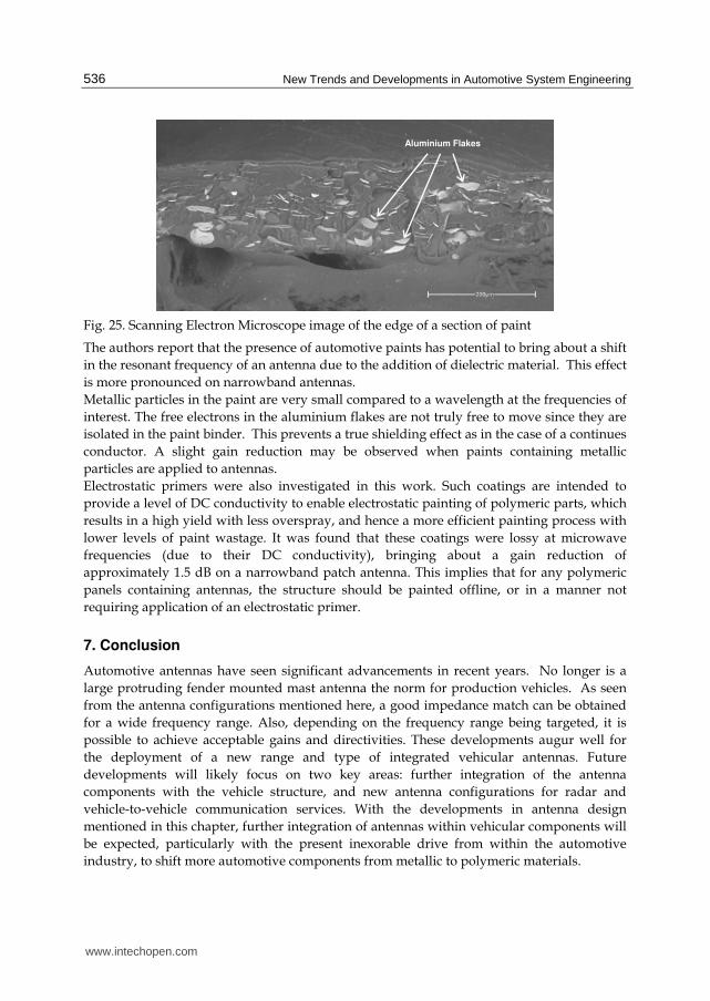
The effect of automotive paints on vehicular antennas was recently studied in depth (Pell et al., n.d.). Two different paint families were investigated including a traditional polyurethane chemistry and the modern water-based paints which are gaining increased use because of their environmental benefits. Both metallic and non-metallic varieties of the paints were investigated. Metallic paints present an interesting scenario for antenna applications. Such paints create a shimmering visual effect by the inclusion of thousands of small flakes of aluminium in the paint (Fig. 25), yet these flakes are inherently conductive. It seems reasonable that the presence of these conductive flakes in the near-field of an antenna may potentially cause severe disruption to proper antenna operation.
www.intechopen.com
New Trends and Developments in Automotive System Engineering
536
Fig. 25. Scanning Electron Microscope image of the edge of a section of paint
The authors report that the presence of automotive paints has potential to bring about a shift
in the resonant frequency of an antenna due to the addition of dielectric material. This effect
is more pronounced on narrowband antennas.
Metallic particles in the paint are very small compared to a wavelength at the frequencies of
interest. The free electrons in the aluminium flakes are not truly free to move since they are
isolated in the paint binder. This prevents a true shielding effect as in the case of a continues
conductor. A slight gain reduction may be observed when paints containing metallic
particles are applied to antennas.
Electrostatic primers were also investigated in this work. Such coatings are intended to
provide a level of DC conductivity to enable electrostatic painting of polymeric parts, which
results in a high yield with less overspray, and hence a more efficient painting process with
lower levels of paint wastage. It was found that these coatings were lossy at microwave
frequencies (due to their DC conductivity), bringing about a gain reduction of
approximately 1.5 dB on a narrowband patch antenna. This implies that for any polymeric
panels containing antennas, the structure should be painted offline, or in a manner not
requiring application of an electrostatic primer.
7. Conclusion
Automotive antennas have seen significant advancements in recent years. No longer is a
large protruding fender mounted mast antenna the norm for production vehicles. As seen
from the antenna configurations mentioned here, a good impedance match can be obtained
for a wide frequency range. Also, depending on the frequency range being targeted, it is
possible to achieve acceptable gains and directivities. These developments augur well for
the deployment of a new range and type of integrated vehicular antennas. Future
developments will likely focus on two key areas: further integration of the antenna
components with the vehicle structure, and new antenna configurations for radar and
vehicle-to-vehicle communication services. With the developments in antenna design
mentioned in this chapter, further integration of antennas within vehicular components will
be expected, particularly with the present inexorable drive from within the automotive
industry, to shift more automotive components from metallic to polymeric materials.
Aluminium Flakes
www.intechopen.com

Advancements in Automotive Antennas
537
8. Acknowledgement
The authors wish to acknowledge other members of the research group, Kefei Zhang and Rahul Gupta. Brendan D. Pell thanks Hao V. Nguyen for sharing his knowledge and experience.
9. References
Beer, S., Adamiuk, G. & Zwick, T. (2009) Novel Antenna Concept for Compact Millimeter-Wave Automotive Radar Sensors. Antennas and Wireless Propagation Letters, IEEE, 8, pp.771-774.
Bogdanov, F., Karkashadze, D., Jobava, R., Gheonjian, A., Yavolovskaya, E., Bondarenko, N. & Ullrich, C. (2010) Validation of Hybrid MoM Scheme With Included Equivalent Glass Antenna Model for Handling Automotive EMC Problems. IEEE Transactions
on Electromagnetic Compatibility, 52 (1), pp.164-172. Cerretelli, M. & Biffi Gentili, G. (2007) Progress in Compact Multifunction Automotive
Antennas. In: International Conference on Electromagnetics in Advanced Applications. pp.93-96.
Economou, L. & Langley, J. (1998) Circular microstrip patch antennas on glass for vehicle applications. IEE Proceedings Microwaves, Antennas and Propagation, 145 (5), pp.416-420.
Eom, S.Y., Son, S.H., Jung, Y.B., Jeon, S.I., Ganin, S., Shubov, A., Tobolev, A. & Shishlov, A. (2007) Design and Test of a Mobile Antenna System With Tri-Band Operation for Broadband Satellite Communications and DBS Reception. IEEE Transactions on
Antennas and Propagation, 55 (11), pp.3123-3133. Gottwald, G. (1998) Numerical Analysis of Integrated Glass Antenna Systems. In: SAE
Technical Paper Series. Paper ID 982386, Society of Automotive Engineers. Gschwendtner, E. & Wiesbeck, W. (2003) Ultra-broadband car antennas for communications
and navigation applications. IEEE Transactions on Antennas and Propagation, 51 (8), pp.2020-2027.
Hoare, E. & Hill, R. (2000) System requirements for automotive radar antennas. In: IEE
Colloquium on Antennas for Automotives. pp.1/1-111. Hopf, J., Reiter, L. & Lindenmeier, S. (2007) Compact multi-antenna system for cars with
electrically invisible phone antennas for SDARS frequencies. In: 2nd International
ITG Conference on Antennas, 2007. INICA '07. pp.171-175. IEEE Std 145-1993 (1993) IEEE Standard Definitions of Terms for Antennas. [Internet].
Available from: <10.1109/IEEESTD.1993.119664>. Iizuka, H., Watanabe, T., Sato, K. & Nishikawa, K. (2005) Modified H-Shaped Antenna for
Automotive Digital Terrestrial Reception. IEEE Transactions on Antennas and
Propagation, 53 (8), pp.2542-2548. Jensen, W.K. (1971) Concealed Windshield Broadband Antenna, U.S. Pat. 3,576,576. Koike, T., Hase, N., Koide, E., Murakami, Y., Izawa, S., Ohira, T., Nagasaka, O., Tanaka, Y. &
Suzuki, T. (1999) Development of a Rear Spoiler with Built-in Antenna. In: SAE
Technical Paper Series. Paper ID 1999-01-0807, Society of Automotive Engineers. Lee, H.S., Jeong-Geun Kim, Songcheol Hong & Jun-Bo Yoon (2005) Micromachined CPW-
fed suspended patch antenna for 77 GHz automotive radar applications. In: The
www.intechopen.com

New Trends and Developments in Automotive System Engineering
538
European Conference on Wireless Technology, 2005. pp.249-252. Available from: <10.1109/ECWT.2005.1617704>.
Lindenmeier, H., Reiter, L., Ramadan, A., Hopf, J. & Lindenmeier, S. (2006) A New Design Principle of Active Receiving Antennas Applied with a High Impedance Amplifier-Diversity-Module in a Compact Multi-Band-Antenna-System on a Plastic Trunk Lid. In: SAE Technical Paper Series. Paper ID 2006-01-0480, Society of Automotive Engineers.
Low, L., Langley, R., Breden, R. & Callaghan, P. (2006) Hidden Automotive Antenna Performance and Simulation. IEEE Transactions on Antennas and Propagation, 54 (12), pp.3707-3712.
Mousavi, P., Fakharzadeh, M., Jamali, S., Narimani, K., Hossu, M., Bolandhemmat, H., Rafi, G. & Safavi-Naeini, S. (2008) A Low-Cost Ultra Low Profile Phased Array System for Mobile Satellite Reception Using Zero-Knowledge Beamforming Algorithm. IEEE Transactions on Antennas and Propagation, 56 (12), pp.3667-3679.
Okada, Y., Tanaka, H. & Yamane, K. (2007) Electromagnetic Field Analysis for Smart Key Antenna. In: SAE Technical Paper Series. Paper ID 2007-01-0943, Society of Automotive Engineers.
Pell, B.D., Sulic, E., Rowe, W.S.T. & Ghorbani, K. (2009) Custom-directional wideband PICA for multi-service vehicular applications. In: APMC 2009. Asia Pacific Microwave
Conference, 2009. pp.1863-1866. Pell, B.D., Sulic, E., Rowe, W.S.T., Ghorbani, K. & John, S. Experimental Study of the Effect
of Modern Automotive Paints on Vehicular Antennas. Accepted (August 2010) for
publication in IEEE Transactions on Antennas and Propagation. Rowan, C.W. & Altgelt, C.A. (1985) When car radios were illegal: A history of early
American and European car radios. In: SAE Technical Paper Series. Paper ID 850019, Society of Automotive Engineers.
Sulic, E., Pell, B., John, S., Gupta, R., Rowe, W., Ghorbani, K., Zhang, K. & Lewis, M. (2007) Parametric Evaluation of Communication Devices in Smart Composite Structures. In: Proceedings of the 5th Australasian Congress on Applied Mechanics (ACAM). Brisbane, Australia, Engineers Australia, pp.477-482.
Sulic, E., Pell, B., John, S., Gupta, R., Rowe, W., Ghorbani, K. & Zhang, K. (2010) Deformation Evaluation of Embedded Antennas in Vehicular Components. In: Proceedings of the World Congress of Engineering 2010. London, UK, pp.2389-2394.
Toriyama, H., Ohe, J., Kondo, H. & Yotsuya, H. (1987) Development of printed-on glass TV antenna system for car. In: 37th IEEE Vehicular Technology Conference, 1987. pp.334-342.
Waterhouse, R. (2008) Printed Antennas for Wireless Communications. Wiley. p30. Wenger, J. (2005) Automotive radar - status and perspectives. In: IEEE Compound
Semiconductor Integrated Circuit Symposium, 2005. CSIC '05. p.4 pp. Available from: <10.1109/CSICS.2005.1531741>.
www.intechopen.com

New Trends and Developments in Automotive System EngineeringEdited by Prof. Marcello Chiaberge
ISBN 978-953-307-517-4Hard cover, 664 pagesPublisher InTechPublished online 08, January, 2011Published in print edition January, 2011
InTech EuropeUniversity Campus STeP Ri Slavka Krautzeka 83/A 51000 Rijeka, Croatia Phone: +385 (51) 770 447 Fax: +385 (51) 686 166www.intechopen.com
InTech ChinaUnit 405, Office Block, Hotel Equatorial Shanghai No.65, Yan An Road (West), Shanghai, 200040, China
Phone: +86-21-62489820 Fax: +86-21-62489821
In the last few years the automobile design process is required to become more responsible and responsiblyrelated to environmental needs. Basing the automotive design not only on the appearance, the visualappearance of the vehicle needs to be thought together and deeply integrated with the “power†developed by the engine. The purpose of this book is to try to present the new technologies developmentscenario, and not to give any indication about the direction that should be given to the research in this complexand multi-disciplinary challenging field.
How to referenceIn order to correctly reference this scholarly work, feel free to copy and paste the following:
Brendan D. Pell, Edin Sulic, Wayne S. T. Rowe, Kamran Ghorbani and Sabu John (2011). Advancements inAutomotive Antennas, New Trends and Developments in Automotive System Engineering, Prof. MarcelloChiaberge (Ed.), ISBN: 978-953-307-517-4, InTech, Available from: http://www.intechopen.com/books/new-trends-and-developments-in-automotive-system-engineering/advancements-in-automotive-antennas