advancements in desalination
TRANSCRIPT

Advancements in Desalination
Jim Lozier, P.ECH2M HILL

Presentation Outline
• The Need for Desalination
• Technology Overview
• Traditional Desalting Technologies
• Evolution and Current Status of Reverse Osmosis
• Recently Commercial Desalting Technologies
• Developmental Desalting Technologies
• Conclusions
2

World-Wide Water Stress Is Increasing
3From National Water IntelligenceResearch, 2912

Water Demand/Supply Gap Drives Need forLower-Cost Desalting Technologies
4From Ng et. Al, Desalination , 308, 2013
Desalination represents best source of new fresh water
<1% readily accessible

Overview of Desalting Technologies
5
Established
Developmental
Emerging
Forward Osmosis(FO)-RO
ElectrochemicallyMediated
CapacitiveDeionization (CDI)
FO-Evap/Condensation
Graphene
Aquaporins(Biomimetric)
Thin-FilmNanocomposite RO

Energy Comparison
Electrical Energy
(kWh/m3)
Thermal Energy
(kWh/m3)
Total Equivalent
Electrical Energy
(kWhe/m3)
Brackish Water RO1 1-1.5 0 1-1.5
Seawater Reverse
Osmosis (SWRO)24-4.5 0 4-4.5
Multiple Effect
Distillation (MED)21 60-70 16-18.5
Multi-Stage Flash
(MSF)25 70-80 22.5-25
1GWI 2008 (TDS<4,000 mg/L)2 Huehmer and Wang 2009 and Sharqawy, 2011

7
Progressive Advancements in ROMembrane Performance
99.0%
99.1%
99.2%
99.3%
99.4%
99.5%
99.6%
99.7%
99.8%
99.9%
3000 4000 5000 6000 7000 8000 9000 10000 11000 12000
Reje
cti
on
(%)
Flow (gpd)
1985
2005
2000
1995
1990
High productivityHigh rejection

Energy consumption of RO has beenreduced significantly
Minimum energyconsumption is 0.78kWh/m3

Emerging Technologies
– Nano-composite RO
– Capacitive Deionization
– Forward Osmosis
9

Thin-Film Nanocomposite PA RO
• Thin-film nanocomposite (TFN) membranes incorporatezeolite particles into PA rejecting layer to increase waterpermeability while retaining salt rejection
• First developed by Dr. Eric Hoek at UCLA
• Commercialized by NanoH2O
• Practical benefit is reduced energy consumption; mostrelevant to seawater desalination
10From Pendergast and Hoek, Energy Environ. Sci., 4, 2011

Capacitive Deionization (CDI)
• Uses activated carbon to adsorb ions under a low voltage electricfield (1-2 V) based on electric double-layer capacitor principle
• System operates in a two-step process:
– Applied electric field produces ion adsorption
– Reversal (or relaxation) of electric field produces desorption
• Several commercially available CDI systems on the market (Enpar,Aqua EWP, Voltea)
• Most suitable for brackish water desalination due to limited specificion adsorption of current carbon materials
11

Capacitive Deionization
• Benefits
– Doesn’t concentrate ions as saltsmore suitable for highscaling waters w/o need for scale inhibitors
– Low pressure, can use plastics to reduce cost and corrosion
• Limitations
– Current carbon materials have:
• limited salt removal (70-80%)
• higher energy consumption than RO (1.8 versus 0.4 kWH/m3for brackish RO)
• Subject to organic fouling (effluent applications)
• New materials promise improved performance
– Carbon nanotubes
– Graphene
12Suppliers: Enpar, Aqua-EWP, Voltea

Forward Osmosis
• Uses osmotic pressure gradient (∆п) to transport water across a semi-permeable membrane
• No energy is needed to drive the water flux of an FO process
• A high osmotic pressure ‘draw’ solution is used as driving forcein the FO process.
• Diluted draw solution must then be re-constituted by removingthe transported water
Courtesy of KAUSTCourtesy of KAUST
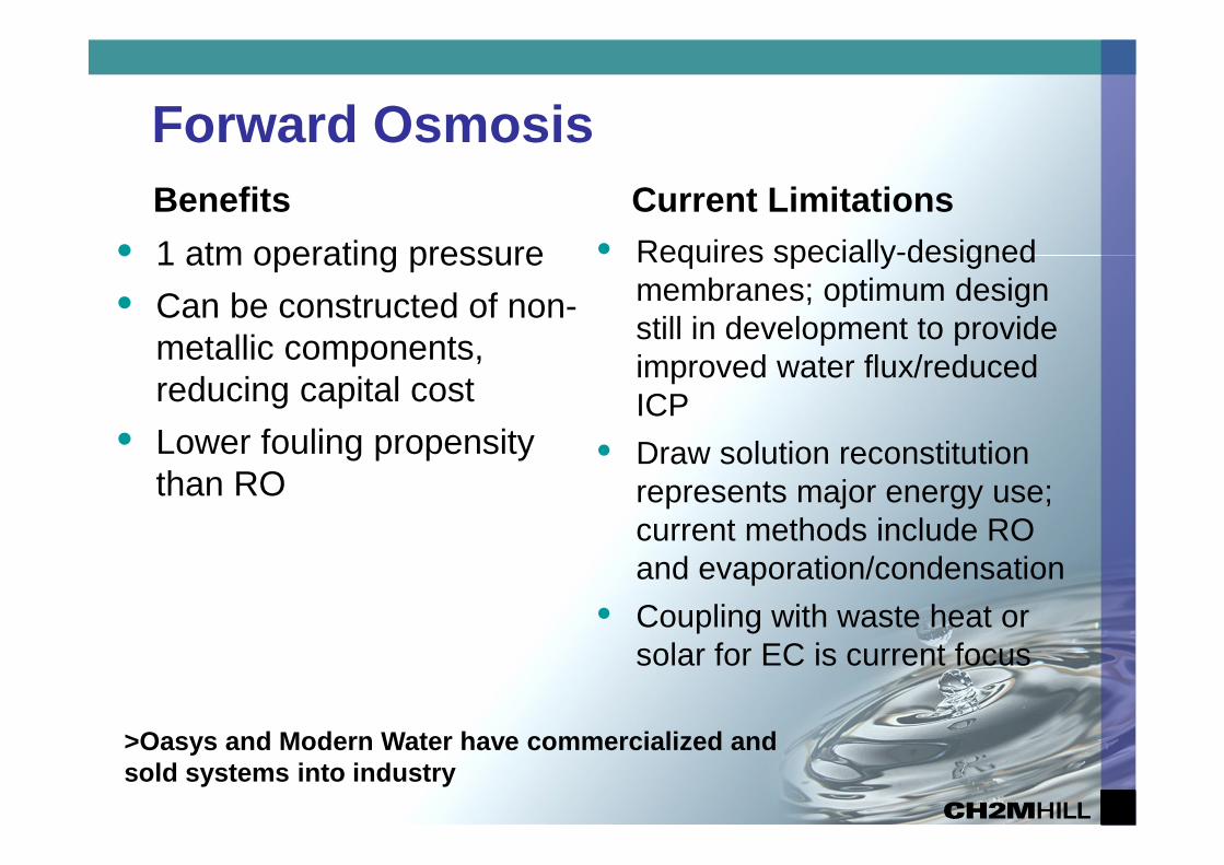
Forward Osmosis
Benefits
• 1 atm operating pressure
• Can be constructed of non-metallic components,reducing capital cost
• Lower fouling propensitythan RO
Current Limitations
• Requires specially-designedmembranes; optimum designstill in development to provideimproved water flux/reducedICP
• Draw solution reconstitutionrepresents major energy use;current methods include ROand evaporation/condensation
• Coupling with waste heat orsolar for EC is current focus
>Oasys and Modern Water have commercialized andsold systems into industry

Near-Term DevelopmentalTechnologies
– Combined Electrodialysis/Electrodeionization
– Forward Osmosis
– Adsorptive/Desorptive Desalination
– Membrane Distillation
– Biomimetric Membranes
– Graphene Nanoporous Membranes
– Microbial
15

Siemens ElectrochemicalDesalination
16
PumpingElectrodialysis(ED)
ContinuousElectrodeionization
(CEDI)
Seawater TDS~ 35,000 ppm
Drinking WaterTDS < 500 ppm
UltrafiltrationPretreatment
• Developed under a Challenge Grant from theGovernment of Singapore (innovative, low energymethod of desalting seawater @ <1.5 kWh/m3*)
• Utilizes a innovative combination of existing processes.
• Initial prototype demonstrate energy consumption of 1.8kWh/m3 while producing product TDS <500 mg/L
*Includes pretreatment, desalting and post-treatment.

Electrochemical Desalination
• Advantages (versus RO)
– Low pressure (40 psi) non-metallic componentry
– Low noiseno high pressure pumps, ERDs or valves
– Chlorine resistant membranes effective control of biofouling
• Current design
– 3 modules in series
• Pilot systems currently in operation
17Graphic courtesy of Siemens

Silica-Based Adsorption/Desorption(AD) Desalination
Developed at National University of Singapore(NUS) ; demonstrated at KAUST
• Uses silica gel to adsorb water vapor evaporatedfrom seawater at low pressure and temperature
• Heat applied to water-adsorbed gel releasesvapor which is then condensed as pure water
• Energy for desorption derived from waste heat orrenewable sources including solar or geothermal

AD Desalination• Features
– reduced scaling and corrosion issues (low temperature salinewater)
– reduced energy requirements - 1.4 kWH/m3 if ‘free’ wasteheat available (versus 3.5 kWH/m3 for SWRO)
– still requires significant capital and operating cost associatedwith cooling load to exhaust heat associated with adsorptionand condensation
Demonstration Unit at KAUST

Membrane Distillation (MD)
• Couples membrane technologyand distillation in a single unitprocess
• Microporous, hydrophobicmembrane passes water vaporwhile retaining liquid water
• Driving force for vapor transport istemperature differential across themembrane, typically 30-50 deg C.
• Rate of vapor transport (water flux)is proportional to temperaturedifferential
• Produces very low TDS distillate
∆T is the driving force
75oC 20oC

Membrane Distillation
• Benefits
– Low-pressure and -energy process
– Potential to use low-grade, waste heat or heat derived from solarenergy
– Lower membrane fouling potentialless expensive pretreatmentthan RO and more robust cleaning capability
– Product quality (TDS) is independent of feed TDS (can treatmore saline sources than RO)
• Limitations
– Higher-flux membranes required to reduce capital cost
– Membrane wetting by organic agents must be minimized toavoid pore filling by water and passage of contaminants
• Commercial systems manufactured by MemSys andMemstill, among others

Longer-Term DevelopmentalTechnologies
– Electrochemically-Mediated Desalination
– Biomimetric Membranes
– Graphene Nanoporous Membranes
22

Biomimetric Membranes - Aquaporins
• Aquaporins are pore-forming proteins, ubiquitous in living cells
• Incorporate water channels that provide extremely high permeabilityand selectivity (orders of magnitude greater than RO)
• Offer best chance to revolutionize desalination but are furthest fromcommercialization (Pendergast et. al, Energy Env. Sciences, 2011)
23
(from Kumar et. al, Proc. Nat’l Acad. of Sci., 2009)side view of AqpZ(from Tang et. al, Desalination, 2013)

Aquaporins – Current status
• Aquaporins have been synthesizedoutside the cell (cell-free synthesis)
• Practical desal membrane has beenfabricated by incorporating Aqpproteoliposomes within aconventional polyamide structure.
• Aqp-PA composite membrane has:– 4.0 LMH/bar (9.8 GFD/psi) permeability
– 96.3% salt rejection
• Other fabrication methods havebeen employed but are limited bycomplexity, lack of robustness orcost
24
(From Tang et. al, Desalination, 2013)
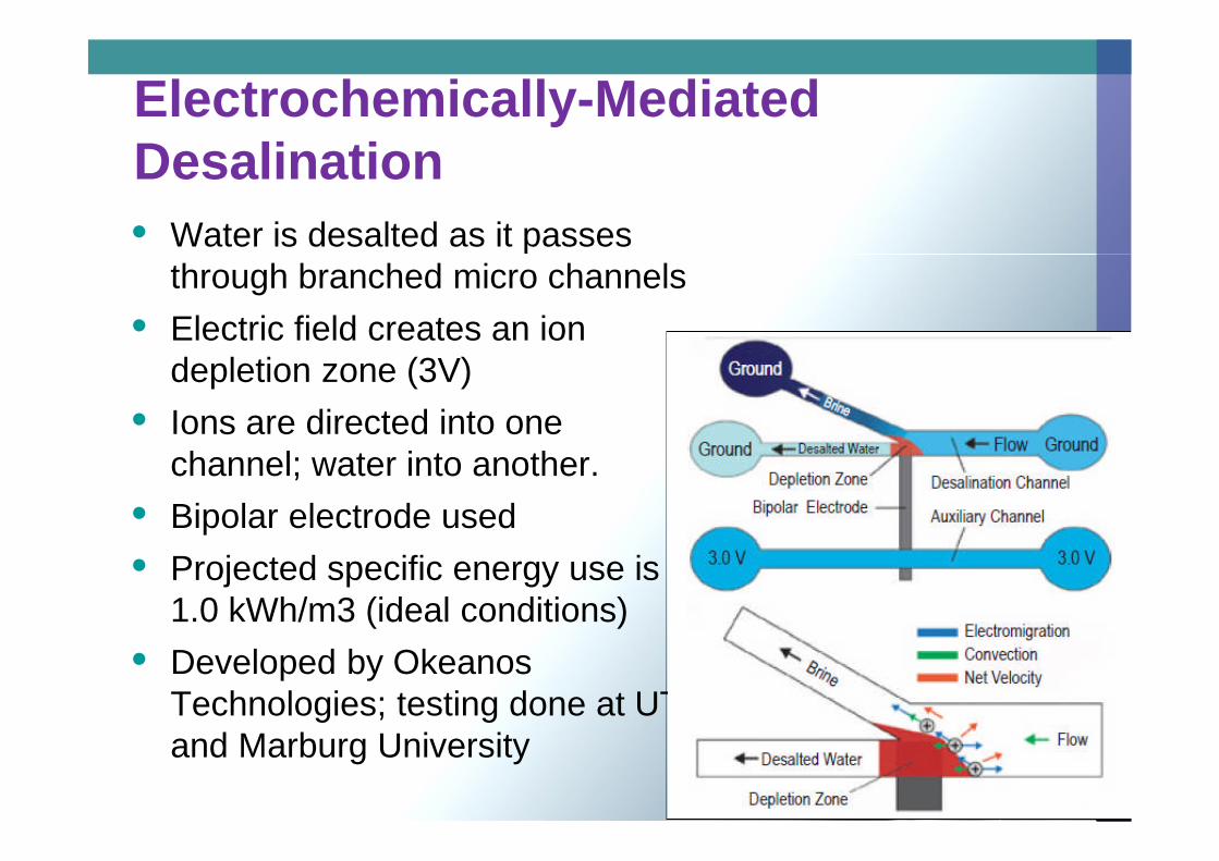
Electrochemically-MediatedDesalination
• Water is desalted as it passesthrough branched micro channels
• Electric field creates an iondepletion zone (3V)
• Ions are directed into onechannel; water into another.
• Bipolar electrode used
• Projected specific energy use is 11.0 kWh/m3 (ideal conditions)
• Developed by OkeanosTechnologies; testing done at UTand Marburg University

Nanoporous Graphene
26
• Cohen-Tanugi and Grossman at MIT/Nano Letters
• Using computer simulations via molecular dynamics, demonstratedthat an atom-thick graphene sheet containing 1-nm holes canseparate NaCl from water at several orders of magnitude the waterflux of RO membranes
• No current methods available to fabricate such graphene sheets
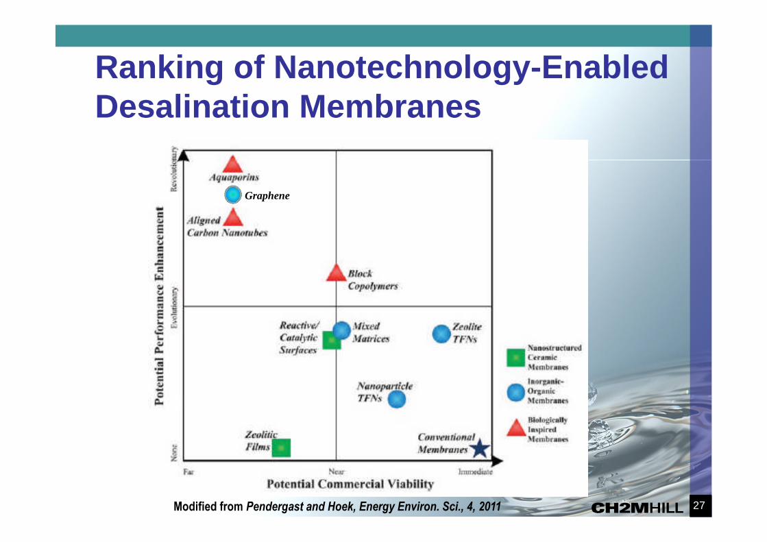
Ranking of Nanotechnology-EnabledDesalination Membranes
27Modified from Pendergast and Hoek, Energy Environ. Sci., 4, 2011
Graphene

Conclusions
• Innovations in desalting technologies are occurring inmany areas and at varying pace.
• Enhancements to RO and ED have occurred and willcontinue.
• Availability of low grade or solar heat for coupling with MD,FO and adsorptive technologies represent means toreduce energy consumption and life cycle costs,particularly for higher salinity feeds.
• Advancements in membrane fabrication are key forcommercialization of MD, FO in short term andnanomaterial, graphene and biomimetric membranes inlong term