advances in ethernet - dspcsp
TRANSCRIPT

AdvancesAdvancesAdvancesAdvancesin in
EthernetEthernetEthernetEthernetYaakov (J) Stein June 2010 Chief ScientistRAD Data Communications

OutlineOutlineOutlineOutline
Modern EthernetModern EthernetVLANs and their usesEthernet servicesEthernet servicesAdditional bridging functionsQoS AspectspLink aggregationEthernet protection mechanismsEFMRPREthernet OAMEthernet securityS h Eth t
AdvEth Slide 2
Synchronous Ethernet

Modern EthernetModern EthernetModern EthernetModern Ethernet
Carrier grade EthernetIEEE 802 viewIEEE 802 viewITU-T viewMEF vieweIETF view
AdvEth Slide 3

What is Ethernet anyway?What is Ethernet anyway?What is Ethernet anyway?What is Ethernet anyway?Ethernet has evolved far from its roots of half-duplex/CSMA/CD LANs
and is hard to pin down today
we may use the term today to describefull duplex 10G point-to-point optical links
Metcalf’s original sketch of Ethernet
p p p p“Ethernet in the first mile” DSL accesspassive optical “GEPON” networksmetro Ethernet networksmetro Ethernet networks“wireless Ethernet” 10M hot spotsetc.
AdvEth Slide 4

“Carrier grade” Ethernet“Carrier grade” EthernetCarrier grade EthernetCarrier grade Ethernet
Ethernet started out as a LAN technologyLAN networks are relatively small and operated by consumerLAN networks are relatively small and operated by consumerhence there are usually no management problems
Eth t t h l i d t f th LAN i tas Ethernet technologies advances out of the LAN environment
new mechanisms are needed, e.g.– OAM– OAM– deterministic (Connection-Oriented) connections– synchronization
the situation is further complicated by different “world views”
of various SDOs working on Ethernet standardization
AdvEth Slide 5

44 viewsviews4 4 viewsviews
IEEE 802 LAN/MAN standards committee (since 1980)IEEE 802 LAN/MAN standards committee (since 1980)
Ethernet is a set of LAN/MAN standards
ITU-T (since 1865 / 1956)
Ethernet is several packet-based layer networks
Metro Ethernet Forum (since 2001)Metro Ethernet Forum (since 2001)
Ethernet is a service provided to a customer
Internet Engineering Task Force (since 1986)
Eth t i IP h l
AdvEth Slide 6
Ethernet is an IP-helper

IEEEIEEE 802802, misc WGs, documents, misc WGs, documentsIEEE IEEE 802802, misc WGs, documents, misc WGs, documents802 LAN/MAN Standards Committee
802-2001802.1 LAN protocols WG
– 802.1D-2004– 802.1Q-2005
802 1 d
Note:
working groups and study groups– 802.1ad– 802.1ah
802.2 LLC
working groups and study groups (e.g 802.1, 802.3) are semi-permanent
projects and task forces802.3 Ethernet WG
– 802.3-2005– 802.3z GbE– 802.3ad link aggregation
p j(e.g. 802.3z, EFM) are temporary
project outputs are usually 802.3ad link aggregation– 802.3ah EFM– 802.3as 2000 byte frames
802.11 Wireless LAN WG (WiFi)
absorbed into main WG document
– 802.11-2005– 802.11a– 802.11b– 802.11g
AdvEth Slide 7
g802.16 Broadband Wireless Access WG (WiMax)802.17 RPR WG
802802..33802802..33actually, IEEE only calls 802.3 Ethernet
802.3 is a large standard, defining
MAC frame format, including VLAN supportmedium specifications and attachment units (UTP, coax, fiber, PON)
repeatersinterfaces (e.g. MII, GMII)
rate autonegotiationli k ti ( ill di l t )link aggregation (we will discuss later)
new projects continue to expand scope802.3aq 10GBASE-LRM802.3ar congestion management802 3as frame expansion
AdvEth Slide 8
802.3as frame expansion

MAC frame formatMAC frame formatMAC frame formatMAC frame format
a MAC frame uses either of the following frame formats :g
64 1518 B
DA (6B) SA (6B) T/L (2B) data (0-1500B) pad (0-46) FCS (4B)
64 – 1518 B
68 – 1522 B
DA(6B) SA(6B) T/L(2B) data (0-1500B) pad(0-46) FCS(4B)VT(2B) VLAN(2B)
8100
802.3as expanded frame size to 2000B (approved September 2006)
AdvEth Slide 9
Note: PHY frame may be larger – e.g. preamble, start-frame deliminator, etc.
Ethernet AddressingEthernet AddressingEthernet AddressingEthernet Addressing
th t i t t t f t l’ h d th dd fi ldthe most important part of any protocol’s overhead are the address fields
Ethernet has both source (SA) and destination (DA) fieldsEthernet has both source (SA) and destination (DA) fieldsthe addresses need to be unique to the network
the fields are 6 bytes in length in EUI 48 formatthe fields are 6-bytes in length in EUI-48 format(once called MAC-48, EUI = Extended Unique Identifier)248 = 281 474 976 710 656 possible addresses248 = 281,474,976,710,656 possible addresses
addresses can be “universally administered” (burned in) or “locally administered” (SW assigned)
AdvEth Slide 10

EUIEUI--4848 and EUIand EUI--6464EUIEUI 48 48 and EUIand EUI 6464EUI-48 used by
Ethernet (802 3)Ethernet (802.3)Token ring (802.5)WiFi (802.11)Bl t thBluetoothFDDISCSI/fiber-channel
IEEE defined a “next generation” 8-byte address called EUI-64EUI-64 used for U 6 used o
IEEE 1394 (firewire)802.15.4 (personal area networks)IPv6 (LSBs of non-temporary unicast address)IPv6 (LSBs of non-temporary unicast address)
EUI addresses usually expressed in hex-hex format
AdvEth Slide 11
Broadcast address is FF-FF-FF-FF-FF-FF

EUI formatEUI formatEUI formatEUI formatOUI1 OUI2 OUI3 EXT1 EXT2 EXT3
X X X X X X U M OUI 00-20-D2
OUI (ex “company name”) is assigned by the IEEE Registration Authority
X X X X X X U M OUI 00 20 D2 is assigned to RAD
OUI (ex company name ) is assigned by the IEEE Registration Authority
each OUI gives 16M addresses (IEEE expects not to run out before 2100)
the LSB of the OUI is the Multicast indicator (0=unicast, 1=multicast)
the next to LSB is the Universal / local bit
0 means UNIVERSALLY allocated address (all assigned OUIs have zero)
1 means there is no OUI - use any unique address
WARNING – bit is reversed in IPv6!
OUI l d b LLC SNAP d i l t l
AdvEth Slide 12
OUIs are also used by LLC SNAP and in slow protocols

Ethernet clientsEthernet clientsEthernet clientsEthernet clientsthe 2-byte Ethertype identifies the client type
assigned by IEEE Registration Authorityall Ethertypes are greater than 0600 (1536 decimal)
some useful Ethertypes :0800 IPv40806 ARP22F3 TRILL22F4 IS-IS8100 VLAN tag8138 Novell IPX8138 Novell IPX814C SNMP over Ethernet86DD IPv68809 slow protocols8847 MPLS unicast8847 MPLS unicast8848 MPLS multicast88D8 CESoETH88A8 Q-in-Q SVID / MAC-in-MAC BVID88F5 MVRP88F6 MMRP88F7 IEEE 1588v28902 CFM OAM
AdvEth Slide 13
see them all at http://standards.ieee.org/regauth/ethertype/eth.txtget your own for only $2,500 ! (RAD has acquired 22E8 for bonding protocol)
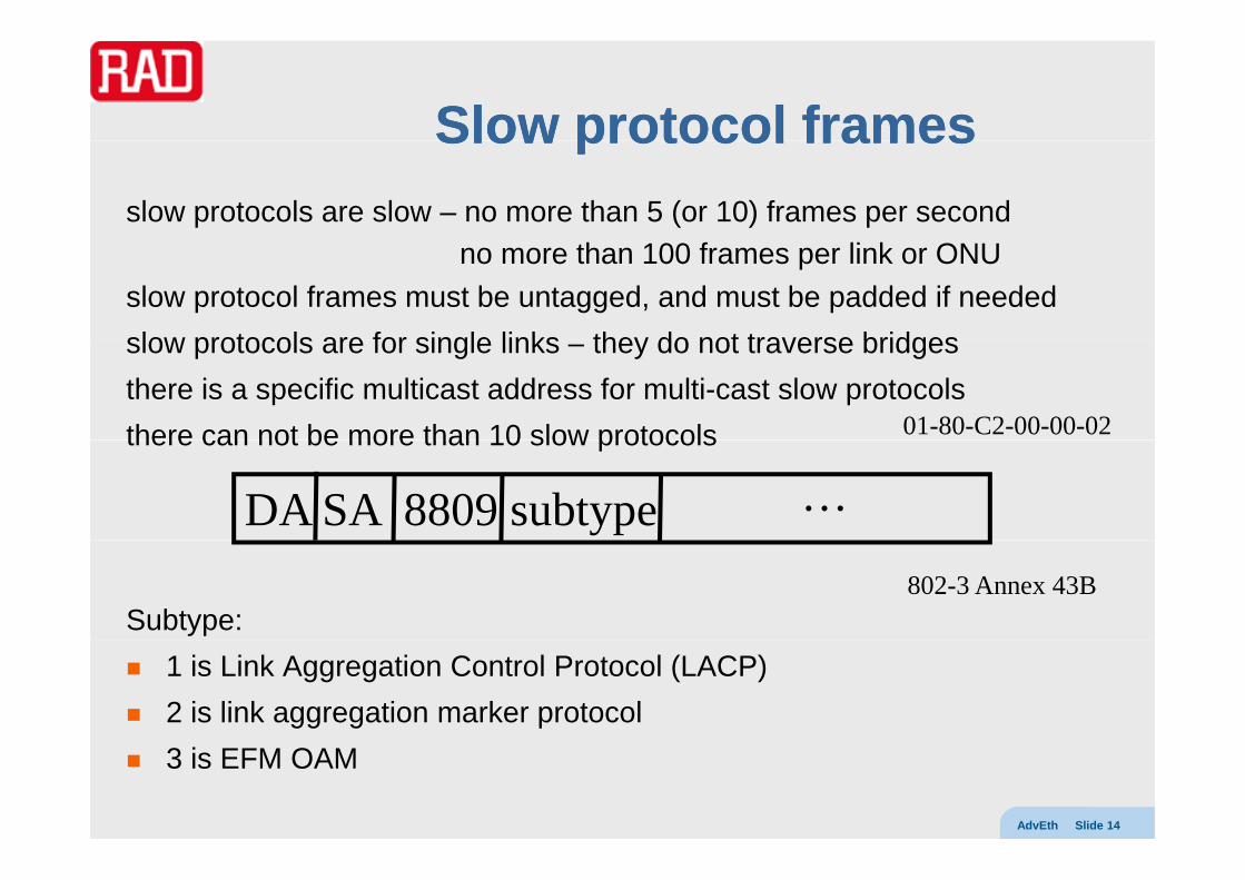
Slow protocol framesSlow protocol framesSlow protocol framesSlow protocol framesslow protocols are slow – no more than 5 (or 10) frames per second
no more than 100 frames per link or ONUslow protocol frames must be untagged, and must be padded if neededslow protocols are for single links they do not traverse bridgesslow protocols are for single links – they do not traverse bridgesthere is a specific multicast address for multi-cast slow protocolsthere can not be more than 10 slow protocols 01-80-C2-00-00-02there can not be more than 10 slow protocols
DA SA 8809 subtype …
Subtype:802-3 Annex 43B
1 is Link Aggregation Control Protocol (LACP) 2 is link aggregation marker protocol
AdvEth Slide 14
3 is EFM OAM

LLCLLCLLCLLCThere are other ways to differentiate clients (other than by Ethertype)
802 2 (Logical Link Control)802.2 (Logical Link Control) first three bytes of payload : – Destination Service Access Point (1B)
S S i A P i t (1B)– Source Service Access Point (1B)– Control Field (1 or 2 B)
DA SA len LLC payload
Example SAPs 04 IBM SNA
06 IP
80 3Com80 3Com
AA SNAP
BC Banyan
AdvEth Slide 15
E0 Novel IPX/SPX
F4 FE CLNS

SNAPSNAPSNAPSNAPDA SA len LLC SNAP payload
Sub-Network Access Protocol LLC parameters plus expanded capabilitiesSNAP can support IPX/SPX, TCP/IP, AppleTalk Phase 2, etc. th fi t i ht b t f l dthe first eight bytes of payload : – Destination Service Access Point (1B) = 0xAA– Source Service Access Point (1B) = 0xAA
Control Field (1B) = 0x03– Control Field (1B) = 0x03– OUI (3B)– Type (2B) (if OUI=00:00:00 then EtherType)
IPX (old Netware method, “raw”) - first 2B of payload FF:FF– Note: standard DSAP/SSAP values can not be FF !
AdvEth Slide 16
RFC 1042 allows IPv4 over Ethernet with SNAP– DSAP=AA, SSAP=AA, Control=3, SNAP=0 followed by Ethertype

ParsingParsingParsingParsing
if EtherType/Length > 1500 then EtherType
else if payload starts with FF-FF then Netware
else if payload starts with AA then SNAPelse if payload starts with AA then SNAP
else LLC e se C
DA SA len/Ethertype XX payload
AdvEth Slide 17

LL2 2 control protocolscontrol protocolsThe IEEE (and others) have defined various control protocols (L2CPs)
Here are a few well-known L2CPs :Here are a few well known L2CPs :
protocol DA referenceSTP/RSTP/MSTP 01 80 C2 00 00 00 802 1D §8 9STP/RSTP/MSTP 01-80-C2-00-00-00
802.2 LLC802.1D §8,9802.1D§17 802.1Q §13
PAUSE 01-80-C2-00-00-01 802.3 §31B 802.3x
LACP/LAMP 01-80-C2-00-00-02Eth T 88 09
802.3 §43 (ex 802.3ad)EtherType 88-09
Subtype 01 and 02Link OAM 01-80-C2-00-00-02
EtherType 88-09Subtype 03
802.3 §57 (ex 802.3ah)
ypPort Authentication 01-80-C2-00-00-03 802.1X
E-LMI 01-80-C2-00-00-07 MEF-16
Provider MSTP 01-80-C2-00-00-08 802.1D § 802.1ad§
Provider MMRP 01-80-C2-00-00-0D 802.1ak
LLDP 01-80-C2-00-00-0EEtherType 88-CC
802.1AB-2009
AdvEth Slide 18
GARP (GMRP, GVRP) Block 01-80-C2-00-00-20 through 01-80-C2-00-00-2F
802.1D §10, 11, 12
Note: we won’t discuss autonegotiation as it is a physical layer protocol (uses link pulses)
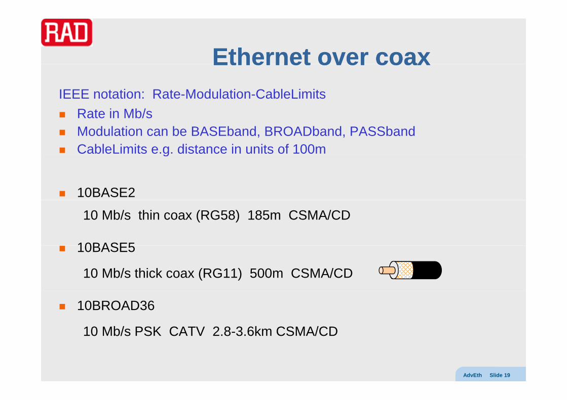
Ethernet over coaxEthernet over coaxEthernet over coaxEthernet over coaxIEEE notation: Rate-Modulation-CableLimits
R t i Mb/Rate in Mb/sModulation can be BASEband, BROADband, PASSbandCableLimits e.g. distance in units of 100mg
10BASE2
10 Mb/s thin coax (RG58) 185m CSMA/CD
10BASE510BASE5
10 Mb/s thick coax (RG11) 500m CSMA/CD
10BROAD36
10 Mb/s PSK CATV 2.8-3.6km CSMA/CD
AdvEth Slide 19

Ethernet over twisted pairsEthernet over twisted pairsEthernet over twisted pairsEthernet over twisted pairs10BASE-T (T=Twisted pair)
10 Mb/s, Manchester, >100m, 2 pairs of UTP, CSMA/CD or FD
100BASE-TX
“fast Ethernet”, 100Mb/s, 4B5B encoding, 2 pair CAT5, FD
1000BASE-T1000BASE-T
(ex 802.3ab, now 802.3 clause 40)
GbE 4D TCM PAM5/EC 100m 4 pairs CAT5/5e/6 FDGbE, 4D-TCM-PAM5/EC, 100m, 4 pairs CAT5/5e/6, FD
10PASS-TS
( EFM 802 3 l 62) 10Mb/ 750 DMT VDSL(ex EFM, now 802.3 clause 62), 10Mb/s, 750m DMT VDSL
2BASE-TL
AdvEth Slide 20
(ex EFM, now 802.3 clause 63), 2Mb/s, 2.7km, SHDSL

Ethernet over optical fiberEthernet over optical fiberEthernet over optical fiberEthernet over optical fiber10BASE-FL
10 Mb/s, P2P, CSMA/CD / FD, 2km, backward-compatible with FOIRL, , , , p
100BASE-FX
100 Mb/s multimode fiber 4B5B 400m HD / 2km FD100 Mb/s, multimode fiber, 4B5B, 400m HD / 2km FD
1000BASE-LX
l λ (1270 1355 ) 8B10B 2k ( i l d ) FD llong λ (1270-1355 nm), 8B10B, >2km (single-mode), FD only
1000BASE-SX
short- λ (850nm near IR), 8B10B, 220m (multi-mode), FD only
10GBASE-SR/LR/ER/LX4
ex 802.3ae, short-range, long-range, extended range, WDM
AdvEth Slide 21

802802..11DD802802..11DD802.1 discusses MAC bridges
802 1D i l large t d d d fi i802.1D is also a large standard, defining
bridge operation (learning, aging, STP, etc.)the architectural model of a bridgethe architectural model of a bridgebridge Protocol and BPDUsGARP management protocolsGARP management protocols
802.1Q is a separate document on VLAN operation
new projects continue to expand scope802.1ad – Q-in-Q802 1af MAC key security802.1af – MAC key security802.1ag – OAM802.1ah – MAC-in-MAC
AdvEth Slide 22
802.1aj – 2-port MAC relay802.1au – congestion notification

802802..11 Baggy pants modelBaggy pants model802802..1 1 Baggy pants modelBaggy pants model
higher layer entitieshigher layer entities(STP entity, bridge management, etc.)
frames
LLC LLCinfo
MAC relay entity MAC entityMAC entity
mediadependentfunctions
mediadependentfunctions
port 1 port 2
N b id h l 2
AdvEth Slide 23
Note: a bridge must have at least 2 portshere we depict exactly 2 ports

Baggy pantsBaggy pants -- forwardingforwardingBaggy pants Baggy pants forwardingforwarding
higher layer entitieshigher layer entities(STP entity, bridge management, etc.)
LLC LLC
MAC relay entity MAC entityMAC entity
receiveframe
transmitframe
port 1 port 2
N l i f 2
AdvEth Slide 24
Note: relay entity passes frame to port 2dependent on port state and filtering database

Baggy pantsBaggy pants -- learninglearningBaggy pants Baggy pants learninglearning
higher layer entitieshigher layer entities(STP entity, bridge management, etc.)
LLC LLC
portlearning
MAC entityMAC entity
portstate
filtering DBreceiveframe
transmitframe
filtering DB
port 1 port 2
N d h f di f k h
AdvEth Slide 25
Note: we do not show forwarding of packet that may occur

Baggy pantsBaggy pants -- STPSTPBaggy pants Baggy pants STPSTP
bridgebridge protocol
entity
LLC LLC
port port
filtering DB
portstate
portstate
RCV XMT RCVXMT
port 1 port 2
N PDU d i d b h b id l i
AdvEth Slide 26
Note: PDUs are sent and received by the bridge protocol entitybridge protocol entity updates filtering DB and port states

Translation to G.Translation to G.805805Translation to G.Translation to G.805805we can redraw the baggy pants model per G.805(from G.8010 Appendix II) Note: drawn for CO case only
ETH/BP ETH/BP
ETHETH
ETH
ETY/ETH ETY/ETH
ETY ETY
AdvEth Slide 27

Extension to N portsExtension to N portsExtension to N portsExtension to N ports
i th b t dihigher layer entities in the baggy pants diagramport 1 and port 2 are identical
so it is enough to draw once
higher layer entities(STP entity, bridge management, etc.)
so it is enough to draw once
if there are many portsthe relay entity becomes
LLC
the relay entity becomesan internal LAN !MAC relay entityMAC entity
mediadependentfunctions
port 1 MACentity
MACentity
MACentity
…
AdvEth Slide 28port 1
entity
port 2
entity
port N
entity

ITUITU--T viewT viewITUITU T viewT viewthe name Ethernet disguises many different layer networks
ETH (MAC layer) is a packet/frame CO/CL network
there is also a VLAN variant called ETH-mETH can run over various server layers, including ETY
ETY (PHY layer) has a number of optionsETY (PHY layer) has a number of options
ETYn n = 1, 2.1, 2.2, 3.1, 3.2, 3.3, 4ETY1 : 10BASE-T (twisted pair electrical; full-duplex only) ETY2.1: 100BASE-TX (twisted pair electrical; full-duplex only; for further study) ETY2.2: 100BASE-FX (optical; full-duplex only; for further study)ETY3.1: 1000BASE-T (copper; for further study) ( pp ; y)ETY3.2: 1000BASE-LX/SX (long- and short-haul optical; full duplex only)ETY3.3: 1000BASE-CX (short-haul copper; full duplex only; for further study) ETY4 : 10GBASE-S/L/E (optical; for further study)
AdvEth Slide 29
ETY4 : 10GBASE-S/L/E (optical; for further study)

ITUITU--T RecommendationsT RecommendationsITUITU T RecommendationsT Recommendations
G.8001 – EoT definitionsG 8010 Ethernet layer network architectureG.8010 – Ethernet layer network architectureG.8011 – Ethernet over Transport services frameworkG 8011 1 – Ethernet private line serviceG.8011.1 Ethernet private line serviceG.8011.2 – Ethernet virtual private line serviceG.8012 – Ethernet UNI and NNIG.8021 – Ethernet transport equipment characteristicsG.8031 – Ethernet linear protection switchingG.8032 – Ethernet ring protection switchingY.1730 – Ethernet OAM - requirements
AdvEth Slide 30
Y.1731 – Ethernet OAM

Ethernet serversEthernet serversEthernet serversEthernet servers
Ethernet can be carried over coaxial cabletwisted copper pairsETYnoptical fibers
synchronous (TDM) networks
packet switched networks (PSN)
AdvEth Slide 31

Ethernet over TDMEthernet over TDMEthernet over TDMEthernet over TDM
SONET/SDH ( E S )over SONET/SDH (see EoS course)PoS (PPP/HDLC)LAPSLAPSGFP
over low-rate TDM
PPP/HDLCGFP
OTNover OTN
GFP
AdvEth Slide 32

Ethernet over PSNEthernet over PSNEthernet over PSNEthernet over PSN
IP (EtherIP RFC 3378)
MPLSMPLS
Ethernet PW (RFC 4448, Y.1415)see PWE3 course
L2VPN services (VPWS/VPLS) see VPLS course
Ethernet (MAC-in-MAC 802.1ah)
ATM (LAN emulation)
AdvEth Slide 33

ETH layer networkETH layer networkETH layer networkETH layer network
ETH is a packet/frame-based layer networkp y
it maintains client/server relationships with other networksnetworks that use Ethernet are Ethernet clients
t k th t Eth t Eth tnetworks that Ethernet uses are Ethernet serverssometimes Ethernet ETY is the lowest server
i.e. there is no lower layer server networkETH is usually connectionless
but connection-oriented variants have been proposed (PBT, PVT, etc)
ETH is a relatively simple layer network it has no real forwarding operations
just filtering and topology pruningj g p gy p git has no real control plane
just STP, GARP, “slow protocol frames”, etc.until recently it had no OAM
AdvEth Slide 34
until recently it had no OAMbut now there are two

ETH adaptationsETH adaptationsETH adaptationsETH adaptationsETH_TFP ETH_FP ETH_TFP ETH_FP s
SRV/ETH SRV/ETH-mSRV/ETH SRV/ETH-m
the adaptation from ETH to the server layer (e.g. ETY) has
SRV_AP SRV_AP
1 ETH Termination Flow Point responsible for DA, SA, P bits, OAM
1 (for ETH-m between 1 and 4094) ETH Flow Point(s)( ) ( )where the ETH CI enters
1 SRV Access Point (SRV can be ETY, but can be other server networks)
AdvEth Slide 35
( , )

Traffic conditioningTraffic conditioningTraffic conditioningTraffic conditioning
G.8010 defines a new function (not in G.805/G.809)
t ffi diti i f ti
ETH_FP
traffic conditioning function:
inputs CI
l ifi t ffi it di t fi d lETH
classifies traffic units according to configured rules
meters traffic units within class to determine eligibility
li f t t ffi itpolices non-conformant traffic units
outputs remaining traffic units as CIETH_FP
technically, the TC function is placed by expanding the ETH Flow Point
AdvEth Slide 36

MEF viewMEF viewMEF viewMEF viewMEF focuses on Ethernet as a service to a customerthe service is provided by a Metro Ethernet Network (any technology / architecture)
the service is seen by the Customer Edge the UNI is the demarcation point between customer and MENeach UNI serves a single customer, presents a standard Ethernet interface
at the UNI CE and MEN exchanged service (MAC) framesconnection between UNIs called an Ethernet Virtual Connection
CE CE
UNI UNI
CE CEMEN
ingress
AdvEth Slide 37
ingressegress

MEF Technical SpecificationsMEF Technical SpecificationsMEF 1 Ethernet Services Model - Phase 1 (obsoleted by MEF 10)MEF 2 Requirements and Framework for Ethernet Service ProtectionMEF 3 Circuit Emulation Requirements MEF 4 MEN Architecture Framework Part 1: Generic Frameworkc ec u e a e o a Ge e c a e oMEF 5 Traffic Management Specification – Phase 1 (obsoleted by MEF 10)MEF 6.1 Metro Ethernet Services Definitions (Phase 2)MEF 7.1 EMS-NMS Information Model (Phase 2)MEF 8 PDH over MEN Implementation Agreement (CESoETH)p g ( )MEF 9 Abstract Test Suite for Ethernet Services at the UNIMEF 10.2 Ethernet Services Attributes (Phase 2)MEF 11 User Network Interface (UNI) Requirements and FrameworkMEF 12 MAN Architecture Framework Part 2: Ethernet Services LayeryMEF 13 User Network Interface (UNI) Type 1 Implementation AgreementMEF 14 Abstract Test Suite for Ethernet Services at the UNIMEF 15 MEN Management Requirements - Phase 1 Network ElementsMEF 16 Ethernet Local Management InterfacegMEF 17 Service OAM Framework and Requirements MEF 18 Abstract Test Suite for Circuit Emulation Services MEF 19 Abstract Test Suite for UNI Type 1MEF 20 UNI Type 2 Implementation Agreement yp p gMEF 21 Abstract Test Suite for UNI Type 2 Part 1 Link OAM MEF 22 Mobile Backhaul Implementation Agreement MEF 23 Class of Service Phase 1 Implementation AgreementMEF 24 Abstract Test Suite for UNI Type 2 Part 2 E-LMI
AdvEth Slide 38
ypMEF 25 Abstract Test Suite for UNI Type 2 Part 3 Service OAMMEF 26 External Network Network Interface - ENNI (Phase 1)

Other reference pointsOther reference pointsOther reference pointsOther reference points
the UNI stands between the CE and MENthe processing functions needed at the CE to connect to the MEN
are called UNI-Cthe processing functions needed at the MEN to connect to the CE
are called UNI-N
between networks elements of a MEN we have I-NNI interfaceswhile between different MENs we have E-NNI interfaces(MEF 4 also defines NI-NNI, SI-NNI and SNI interfaces)
CEUNI
MENUNI-C UNI-N
E-NNII-NNI MEN-y
AdvEth Slide 39
MEN-x

EVCsEVCsEVCsEVCsa public MEN can not behave like a shared LAN
since ingress frames must not be delivered to incorrect customerssince ingress frames must not be delivered to incorrect customers
an association of 2 or more UNIs is called an EVCingress frames must be delivered only to UNI(s) in the same EVC
when several UNIs frames may be flooded to all or selectively forwarded
frames with FCS errors must be dropped in the MEN (to avoid incorrect delivery)
a single UNI may belong to several EVCs (differentiated by port and/or VLAN ID)
HQEVC 1 EVC 2
HQMENEVCs 1, 2, 3
AdvEth Slide 40
EVC 3

EVC typesEVC typesEVC typesEVC typesa point-to-point EVC associates exactly 2 UNIs
the service provided is called E LINE [MEF 6] UNIUNIthe service provided is called E-LINE [MEF-6]
a multipoint-to-multipoint EVC connects 2 or more UNIs
UNIMENUNI
p p
Note: MP2MP w/ 2 UNIs is different from P2P (new UNIs can be added)
unicast frames may flooded or selectively forwardedunicast frames may flooded or selectively forwardedbroadcast/multicast frames are replicated and sent to all UNIs in the EVC
the service provided is called E-LAN [MEF-6]
we will see more details on Ethernet services laterUNI
UNIMENUNI
AdvEth Slide 41
UNI

New MEF Model (New MEF Model (1212..11))New MEF Model (New MEF Model (1212..11))MEF is updating their architecture model
Metro Carrier so MEN CENEVC is no longer a transport entityEthernet Connection (EC) is the entity that connectsEthernet Connection (EC) is the entity that connects Ethernet flow termination pointsECs traversing several CENs are composed of EC segments (ECS)Operator Virtual Connections (OVCs) connect ENNIs with other ENNIs or UNIs
CEN 2CEN 1
UNI-N UNI-NUNI-C UNI-C
UNI UNI
ENNI-N ENNI-N
ENNISubscriber SubscriberCEN 2CEN 1
EVC
SubscriberA B
S-EC
AdvEth Slide 42
S-ECSsOVCs
O-ECSs
S EC
SP-EC
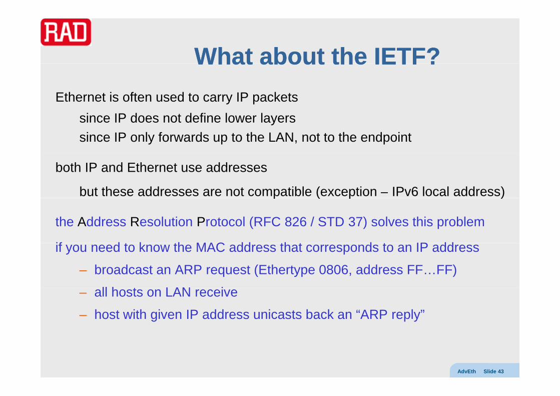
What about the IETF?What about the IETF?What about the IETF? What about the IETF? Ethernet is often used to carry IP packets
since IP does not define lower layerssince IP only forwards up to the LAN, not to the endpoint
both IP and Ethernet use addresses
but these addresses are not compatible (exception – IPv6 local address)p ( p )
the Address Resolution Protocol (RFC 826 / STD 37) solves this problem
if d t k th MAC dd th t d t IP ddif you need to know the MAC address that corresponds to an IP address
– broadcast an ARP request (Ethertype 0806, address FF…FF)
ll h t LAN i– all hosts on LAN receive
– host with given IP address unicasts back an “ARP reply”
AdvEth Slide 43

Other ARPOther ARP--like protocolslike protocolsOther ARPOther ARP like protocolslike protocolsother related protocols (some use the ARP packet format)
GARP (gratuitous ARP – WARNING not 802.1 GARP)host sends its MAC-IP binding without request (e.g. backup server)
Proxy ARProuter responds to ARP request to capture frames
Reverse ARP, BOOTP, DHCPhost sends its MAC and wants to know its IP address
Inverse ARPframe-relay station unicasts DLCI to find out remote IP address
ARP mediationmediate over L2VPN between networks using different ARPs (e.g. Ethernet on one side and FR on the other)
AdvEth Slide 44
(e g e e o o e s de a d o e o e )

VLANsVLANsVLANsVLANs
VLANstagging (802 1Q)tagging (802.1Q) SVL and IVL switchesVLAN stacking stac gPBN and PBBNPBT MPLS-TP
AdvEth Slide 45

Virtual LANsVirtual LANsin standard practice each LAN needs its own infrastructure
1 broadcast domain per set of cables and hubsll t ti LAN ll t ffiall stations on LAN see all traffic
we may want a single physical infrastructure to support many LANssimpler and less expensive than maintaining separate infrastructuressimpler and less expensive than maintaining separate infrastructuresmultiple low-speed LANs on one high-speed infrastructuresegment broadcast domains (lower BW/processing) without routerssecurity for different departments in company / groups in campussecurity for different departments in company / groups in campus
separation may be based on switch ports or MAC address or VLAN ID (tag)
ill t d l d l i t VLAN h ( Q )we will not delve deeply into VLANs here (see e.g. 802.1Q Appendix D)I assume that this is treated in elementary Ethernet course
port-basedVLAN
AdvEth Slide 46

VirtualVirtual LANsLANs (cont.)(cont.)Virtual Virtual LANs LANs (cont.)(cont.)
initially there were proprietary solutions to tagging
802.1Q & 802.1p projects defined format, protocols, and procedures802.1p results were incorporated into 802.1D-1998p p– priority
802.1Q intentionally left separate and NOT incorporated considered sufficiently distinct from non-VLAN bridgingy g g– in particular, baggy pants model enhanced– new protocol – GVRP (see below)
802.1ad and 802.1ah further extend tagging formats and procedures
VID VLAN
AdvEth Slide 47

VLAN ID (VID)VLAN ID (VID)VLAN ID (VID)VLAN ID (VID)
bi C2B VLAN tag
P-bits(3b) CFI(1b) VID(12b)Canonical Format Indicator
802.1Q mandates 12 bit VID (carried after Ethertype 8100)2 bytes carry P (priority) bits, CFI (not important here, always 0) and VID4094 possible VID values (0 and 4095 are reserved)p ( )VID=0 frames are priority tagged, able to carry P bits
VLAN-aware switches take VID into account when forwardingtake VID into account when forwardingperform VID insertion/removalnever output a priority-tagged frame
when VLAN aware switch receiveswhen VLAN-aware switch receivesVLAN tagged frame – treats according to VIDuntagged frame – may push permanent VID (PVID) of receive portpriority tagged frame treated like untagged frame (VLAN tag MAY be added)
AdvEth Slide 48
priority-tagged frame treated like untagged frame (VLAN tag MAY be added)
Insertion / removal of VLAN tag necessitates recomputing FCS and adjusting padding
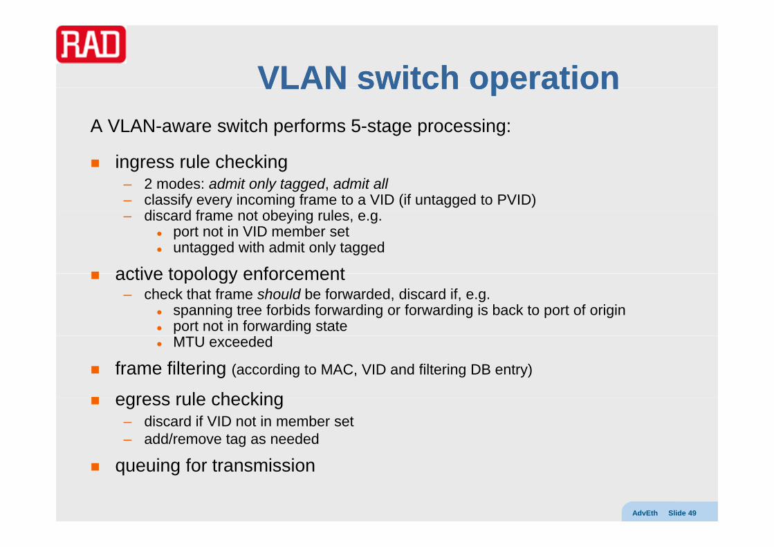
VLAN switch operationVLAN switch operationVLAN switch operationVLAN switch operationA VLAN-aware switch performs 5-stage processing:
ingress rule checking – 2 modes: admit only tagged, admit all– classify every incoming frame to a VID (if untagged to PVID)
di d f t b i l– discard frame not obeying rules, e.g. port not in VID member setuntagged with admit only tagged
active topology enforcementactive topology enforcement– check that frame should be forwarded, discard if, e.g.
spanning tree forbids forwarding or forwarding is back to port of originport not in forwarding stateMTU exceeded
frame filtering (according to MAC, VID and filtering DB entry)
egress rule checkingegress rule checking– discard if VID not in member set– add/remove tag as needed
i f t i i
AdvEth Slide 49
queuing for transmission
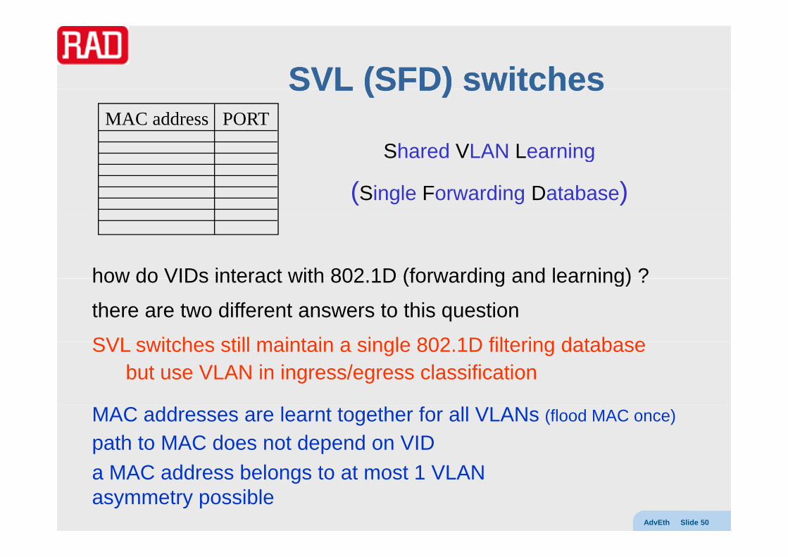
SVL (SFD) switchesSVL (SFD) switchesSVL (SFD) switchesSVL (SFD) switches
Shared VLAN LearningMAC address PORT
Shared VLAN Learning
(Single Forwarding Database)
how do VIDs interact with 802 1D (forwarding and learning) ?how do VIDs interact with 802.1D (forwarding and learning) ?
there are two different answers to this question
SVL switches still maintain a single 802 1D filtering databaseSVL switches still maintain a single 802.1D filtering databasebut use VLAN in ingress/egress classification
MAC addresses are learnt together for all VLANs (flood MAC once)
path to MAC does not depend on VIDMAC dd b l t t t 1 VLAN
AdvEth Slide 50
a MAC address belongs to at most 1 VLANasymmetry possible

Asymmetry caseAsymmetry caseAsymmetry caseAsymmetry case
1
2
3
green PC can talk to server untagged frames on port 1 are tagged with VID=1tags removed when sent to servertags removed when sent to server
red PC can talk to server untagged frames on port 2 are tagged with VID=1t d h t ttags removed when sent to server
server can reply to both untagged frames are tagged with VID=3gg ggtags removed when sent out of ports 1 or 2
but green and red PCs can NOT talk to each otherVID 1 traffic can not be sent to red PC with MAC associated with VID 2
AdvEth Slide 51
VID=1 traffic can not be sent to red PC with MAC associated with VID=2VID=2 traffic can not be sent to green PC with MAC associated with VID=1

IVL (MFD) switchesIVL (MFD) switchesIVL (MFD) switchesIVL (MFD) switchesMAC address PORT
MAC address PORT
VID=1
VID=2MAC address PORT
MAC address PORT
MAC address PORT
VID=2
VID=3…
Independent VLAN Learning
(Multiple Forwarding Databases)MAC address PORT
IVL switches maintain separate 802.1D filtering databases per VID
MAC addresses are learnt independently for each VID (more flooding)1 MAC dd b l t l VLAN1 MAC address can belong to several VLANs
but path to MAC depends on VIDasymmetry impossible
AdvEth Slide 52
Note: IVL switch can be implemented as 60 (48+12) bit lookup

VLAN stackingVLAN stackingVLAN stackingVLAN stacking
we tag Ethernet frames by using Ethertype 8100we tag Ethernet frames by using Ethertype 8100
type data pad FCSDA SA 8100 VLAN 1
first Ethertype is set to 8100second Ethertype is payload protocol (as in untagged frame)but what if we add another Ethertype to 8100 ?
d t d FCS8100 VLAN 2 8100 VLAN 1SADA t
this is called VLAN stackingW i
data pad FCS8100 VLAN 2 8100 VLAN 1SADA type
or (for obvious reasons) Q-in-Q
stacking is not mentioned in 802.1Q
Warning:although superficially Q-in-Q looks like an MPLS stack, th i t k l i h
AdvEth Slide 53
but not ruled out either! there is no network layering here –the DA remains the same!

Provider BridgesProvider Bridges –– 802802..11adadProvider Bridges Provider Bridges 802802..11adadwhy stack VLANs? CE CEPE PEPBN1 reason is for Provider Bridge Networks
customers may use VIDs for internal reasons and will want them maintained across the PBN
but what if multiple customers use the same VIDs ? 802.1adapproved Dec 2005
the provider must either:manage customer VIDs – allocate ranges to customers
t i d
published May 2006
– swap at ingress and egress ortreat them as Customer VIDs, and push a Service VID (customer ID)
CVID=1…100SVID=1…2 CECE
AdvEth Slide 54
CVID=1…100 PE PECECE

CVID and SVIDCVID and SVIDCVID and SVIDCVID and SVIDcustomer frames have C-TAGs, may only have priority S-TAGs
PBN f h S TAG d ll h C TAGPBN frames have S-TAGs and usually have C-TAGsC-TAG contains a C-VIDS-TAG contains an S-VID
C-TAGs are standard format VLAN tags802.1ad S-TAGs are similar, but use Ethertype 88A8
since they have Drop Eligible Indicator instead of CFIsince they have Drop Eligible Indicator instead of CFI
service transparencyPE inserts S-TAG C-TAG becomes invisible to PBNPE inserts S TAG, C TAG becomes invisible to PBNPE removes S-TAG, C-TAG becomes visible to customer network
D
C
P S-VID88A8 (S-TAG)DEI
AdvEth Slide 55
P C-VID8100 (C-TAG)CFI

Problems with PBNsProblems with PBNsProblems with PBNsProblems with PBNs
Q-in-Q PBNs simplify provider-customer interface, but
are limited to 4K SVIDs, i.e. 4K customers(VLANs derive from enterprise (not carrier) applications)(VLANs derive from enterprise (not carrier) applications)do not provide true client/server (decoupled) relationship– customer VIDs are hidden
but not customer MAC addresses– no true OAM trace functionality
provider switches still have to learn customer MAC addressesprovider switches still have to learn customer MAC addresses
we would really like full decoupling, i.e. a client/server relationshipthis can be done via MAC-in-MACthis can be done via MAC in MAC
AdvEth Slide 56

Progress to MACProgress to MAC--inin--MACMACProgress to MACProgress to MAC inin MACMAC
802.1Dpayload FCSDA SA T
802 1QVLAN8100 payload FCSDA SA
802.1QT
S-TAG88A8 C-TAG8100 payload FCSDA SA802.1ad
T
B-TAG88A8 I-TAGTBDB-SAB-DA
S TAG88A8 C TAG8100 l d FCSDA SA
…802.1ah
TS-TAG88A8 C-TAG8100 payload FCSDA SA T
AdvEth Slide 57

PBBN PBBN 802802..11ahah CE802 1ahCE
CE CEPBN
CE
BE PE802 1D or 802 1Q interface
802.1ad interface
802.1ah approved – June 2008
CE PBN
CE
CEN
CEPBBNBE BE
BE
PE802.1D or 802.1Q interface
BB
Provider Backbone Bridge Networksbackbone provider is a “carrier’s carrier”
CE
PBNPE802.1ah interface
backbone provider is a carrier s carrierBackbone Edge switches use
I-TAGs with I-SIDB TAG ith B VID
CECE CE
B-TAG with B-VIDone or more I-TAGs and a B-TAG
I-TAG is a new format, I-SID is a 24-bit label (no more 4K limitation)( )
4B I-TAG
AdvEth Slide 58
I-P(3b) I-DEI(1b) RES(4b) ISID (24b)

PBT (PBBPBT (PBB--TE)TE) 802802..11QayQayPBT (PBBPBT (PBB TE) TE) 802802..11QayQayProvider Backbone Transport builds on 802.1ah PBBNs
to achieves reliable deterministic carrier class behaviorto achieves reliable, deterministic, carrier-class behavior
802.1ah gives backbone provider its own addressing space (MAC + VLAN)
dd t h d ith t ( d t l t MAC )addresses not shared with customer (no need to learn customer MACs)and so provider is free to use address space as it sees fit
we saw before that IVL switches forward based on 60 bit addresseswe saw before that IVL switches forward based on 60-bit addressesbut their capabilities limited due to limitations of STP, flooding, etc
but most IVL switches allow static FID (preconfigured forwarding behavior)but most IVL switches allow static FID (preconfigured forwarding behavior)and support turning off learning/STP/flooding/aging
we can thus set up pure connection-oriented topology
BVID=1
p p p gy
we can use management (OSS)or control plane protocols (e.g. RSVP-TE) to populate FID tables
BVID=2
AdvEth Slide 59
p p ( g ) p p(IETF GELS/CCAMP, ITU G.pbt)

What about MPLS ?What about MPLS ?What about MPLS ?What about MPLS ?
th f i t Eth t f id t kanother way of carrying customer Ethernet frames over a provider networkis to use MPLS (Ethernet PW, VPWS, VPLS)
(see MPLS, PWE and VPLS courses)
also complete decouples customer and provider networks
furthermore, MPLS is carrier-class (deterministic, CO, OAM, etc.)
and widely deployed (for IP and L3VPN applications)
MPLS can be carried over carrier SONET/SDH networks
MPLS l b l PW l b l CW C TAG8100 l d FCSTSADAMPLS label PW label CW C-TAG8100 payload FCST SADA
AdvEth Slide 60

PBT vs. MPLSPBT vs. MPLSPBT vs. MPLSPBT vs. MPLS
both achieve complete client/server decoupling
PBT exploits existing IVL switchesbut many switches today can do MPLS forwarding– but many switches today can do MPLS forwarding
Ethernet frame has SA, so OAM traceback easy– MPLS swaps labels and contains only destination semanticsp y
so need OAM for CV and mismerge detectionPBT can co-exist with bridged Ethernet
MPLS has highly developed control plane– Ethernet presently requires manual configuration– can use OSS but not standardizedcan use OSS, but not standardized– may be able to use GMPLS control plane (GELS)
MPLS can transport non-Ethernet clients (IP, PWs)
AdvEth Slide 61

MoreMore alternativesalternativesMore More alternativesalternativesthere are other ways to
set up CO connectionsset up CO connections avoid use of customer MAC addresses
MPLS-TP (Transport Profile)MPLS-TP (Transport Profile)add an MPLS label to the ETH overheadin provider network switch solely based on label
similar to regular MPLS, butperformed by switch instead of LSR various transport extensions such as linear/ring protection, OAMvarious transport extensions such as linear/ring protection, OAM
TRILL (Transparent Interconnection of Lots of Links ) - see later oninvented by Radia Perlman (inventor of STP and IS IS)invented by Radia Perlman (inventor of STP and IS-IS)uses IS-IS directly on MAC addresses (no need to configure IP addresses)adds outer MAC header + shim header (with TTL)i l t l " t h" ( l d l )
AdvEth Slide 62
is completely "no-touch" (plug-and-play).finds optimal paths
Ethernet servicesEthernet servicesEthernet servicesEthernet services
EVCs and bundlingEVCs and bundling
Ethernet Private Line (EPL)
Ethernet Virtual Private Line (EVPL)Ethernet Virtual Private Line (EVPL)
Ethernet Private LAN (EPLAN)
Eth t Vi t l P i t LAN (EVPLAN)Ethernet Virtual Private LAN (EVPLAN)
AdvEth Slide 63

Ethernet servicesEthernet servicesEthernet servicesEthernet serviceswe previously defined
E LINE point to point layer 2 serviceE-LINE point-to-point layer 2 serviceE-LAN multipoint-to-multipoint Ethernet service
but MEF and ITU have gone a step furtherbut MEF and ITU have gone a step further
MEF 6 splits E-LINE into EPL and EVPLMEF 6 splits E LINE into EPL and EVPLITU followed - Recommendations: G.8011.1 and G.8011.2
and E-LAN can be split into EPLAN and EVPLANp
these distinctions are made in order to live up to SLAs i id d fi d i tt ib ti.e. provide defined service attributes
AdvEth Slide 64

EVCs revisitedEVCs revisitedEVCs revisitedEVCs revisitedin our previous discussion of EVCs we didn’t mention VLANs
li t EVC b di ti i h d b VLAN IDwe now realize customer EVCs can be distinguished by VLAN IDs
if the transport infrastructure is ETH, there may be an SVID
if the customer wants to have several EVCs, there will be a CVID (here we simply mean the customer’s 802.1Q VLAN ID)
the provider may promise “VLAN preservation”i.e. not change CVIDs (untagged remain untagged)i.e. not change CVIDs (untagged remain untagged)
at the UNI-N there will be a CVID to EVC map (see MEF 10.1)
there can be three types of maps:all to oneone to one (not MEF 10 term)
AdvEth Slide 65
one to one (not MEF 10 term)arbitrary (not MEF 10 term)

All to one bundling mapAll to one bundling mapAll to one bundling mapAll to one bundling map
all frames (independent of CVID) are mapped to the same EVCall frames (independent of CVID) are mapped to the same EVCVLAN preservationno need for customer-provider coordinationpwhen p2p: similar to leased linewhen mp2mp: similar to TLSsupport multiple customer EVCs by different switch portscan’t mix all to one switch with other map types in single EVC
1 EVC 1
all CVIDs all to one
1501
2
EVC 1
EVC 2arbitrary1 .. 100101 200
150
150
AdvEth Slide 66
all CVIDs 101 .. 200150
wrong switch gets response

One to one bundling mapOne to one bundling mapOne to one bundling mapOne to one bundling map
h CVID d t diff t EVCeach CVID mapped to a different EVCuntagged (and priority tagged) mapped to default EVCsupport multiple EVCs from a single switch portsupport multiple EVCs from a single switch portno VLAN preservation can makes customer configuration easiersimilar to frame relay (DLCI identifies PVC)
CVID=1001C
CVID 1EVC 1CVID=1
CVID=2CVID=1002
SP CCVID 1
CVID=1
EVC 2
default EVC
CVID 2
CVID=1003
SP CCVID=1
CVID=1
AdvEth Slide 67
default EVCuntagged
CVID 1003
C

Arbitrary bundling mapArbitrary bundling mapArbitrary bundling mapArbitrary bundling mapmultiple CVIDs per EVCbut multiple EVCs per portVLAN preservation can ensure customer traffic only goes to sites where VLAN is neededcan ensure customer traffic only goes to sites where VLAN is neededmore efficient BW useneed customer and SP coordination as to CVID – EVC map
can coexist with one to one switches on same EVC
EVC 1
EVC 2
CVID=1 … 100
CVID=101 … 200 EVC 2
default EVCuntagged
AdvEth Slide 68

EPLEPLEPLEPLEthernet Private Line is a dedicated-BW E-LINE (p2p) service
transport network seems to be a transparent cable
no frame loss unless FCS errorsS
transport layer may benative Ethernet – dedicated to single EVC (e g 100 Mb/s)
CE CEPE PESP
native Ethernet – dedicated to single EVC (e.g. 100 Mb/s)TDM or SONET/SDH timeslot (e.g. X.86, GFP)VPWS service in TE tunnel
ITU further divides EPL into type 1 – terminate ETY, transport MAC frame over server (SDH/GFP-F, MPLS)t 2 t t t t ( GFP T)type 2 – transparent transport (e.g. GFP-T)native (special case for 10GBASE-W)
AdvEth Slide 69
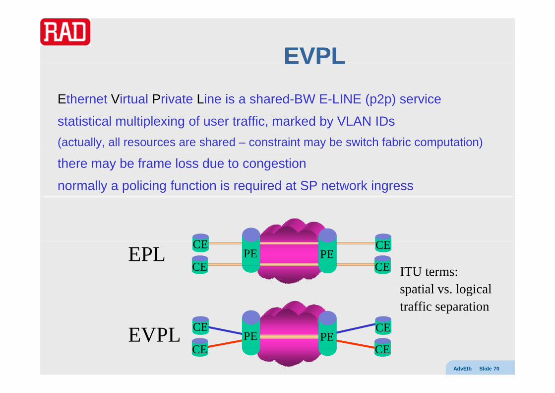
EVPLEVPLEVPLEVPLEthernet Virtual Private Line is a shared-BW E-LINE (p2p) service
statistical multiplexing of user traffic, marked by VLAN IDs(actually, all resources are shared – constraint may be switch fabric computation)
there may be frame loss due to congestion
normally a policing function is required at SP network ingress
CE CE
CE CEPE PE
CE CEEPLITU terms:
ti l l i l
CE CEEVPL
spatial vs. logical traffic separation
AdvEth Slide 70
CE CEPE PE
CE CEEVPL

EPLANEPLANEPLANEPLAN
Ethernet Private LAN is a dedicated-BW E-LAN service
possible SP topologiesfull mesht
CE PEPE CEstarmain switch PE
CE
PE
PEPE CEP CE
CECE PEPE CE
PE
CE
AdvEth Slide 71

EVPLANEVPLANEVPLANEVPLANEthernet Virtual Private LAN is a shared-BW E-LAN service
statmuxed BW and switch fabric are shared among customers
useful service, but most difficult to manage (not yet studied)
when server is MPLS, this is VPLS
best effort version is widely deployed
CE
CE PEPE CECE
CE
CEPE
CECE CE
CE
AdvEth Slide 72

Additional bridging functionsAdditional bridging functionsAdditional bridging functionsAdditional bridging functions
GARP GVRP GMRP (802 1ak)GARP, GVRP, GMRP (802.1ak)
rapid spanning tree (802.1w)
lti l i t (802 1 2002)multiple spanning trees (802.1s-2002)
Rbridges
AdvEth Slide 73
GARPGARP ((802802..11D clauseD clause 1212))GARP GARP ((802802..11D clause D clause 1212))
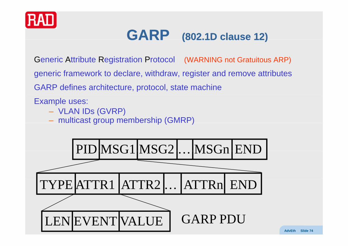
Generic Attribute Registration Protocol (WARNING not Gratuitous ARP)
generic framework to declare, withdraw, register and remove attributes
GARP defines architecture, protocol, state machine
Example uses:– VLAN IDs (GVRP)– multicast group membership (GMRP)g p p ( )
PID MSG1 MSG2 MSGn ENDPID MSG1 MSG2 … MSGn END
TYPE ATTR1 ATTR2 … ATTRn END
AdvEth Slide 74
LEN EVENT VALUE GARP PDU

GVRPGVRP ((802802..11Q clauseQ clause 1111))GVRP GVRP ((802802..11Q clause Q clause 1111))GARP VLAN Registration Protocol performs automatic VLAN configuration
to properly process VLAN tagged frames the VLAN switches need to knowto properly process VLAN tagged frames, the VLAN switches need to know the VLANs in which it participateswhich ports to use for VLAN members
VLAN configuration of all switches needs to be consistent
802.1Q allows:static provisioning of VLAN membership information (via management mechanisms)dynamic configuration and distribution of VLAN membership info
to add a new switch to a VLAN:with static provisioning need to configure every switch p g g ywith GVRP need to configure only one switchGVRP then sends out info needed to configure all the other switches
AdvEth Slide 75
GMRPGMRP ((802802..11D clauseD clause 1010))GMRP GMRP ((802802..11D clause D clause 1010))
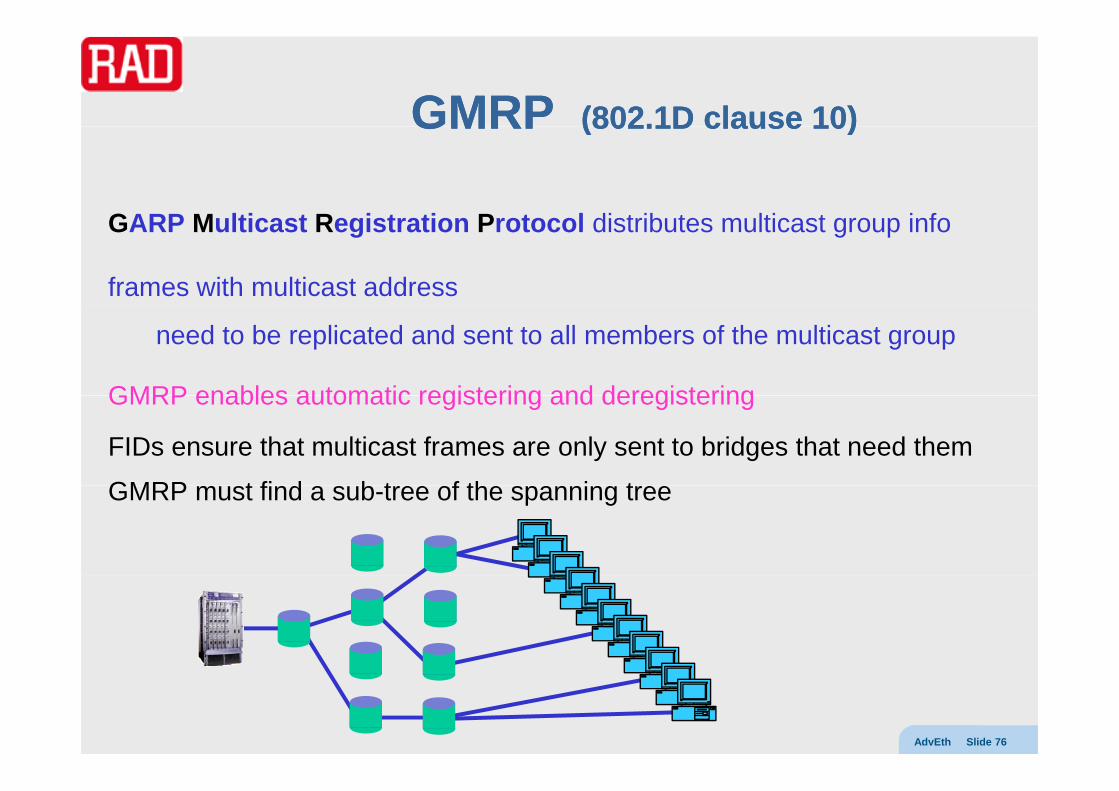
GARP M lti t R i t ti P t l di t ib t lti t i fGARP Multicast Registration Protocol distributes multicast group info
frames with multicast address
need to be replicated and sent to all members of the multicast group
GMRP enables automatic registering and deregisteringGMRP enables automatic registering and deregistering
FIDs ensure that multicast frames are only sent to bridges that need them
GMRP t fi d b t f th i tGMRP must find a sub-tree of the spanning tree
AdvEth Slide 76
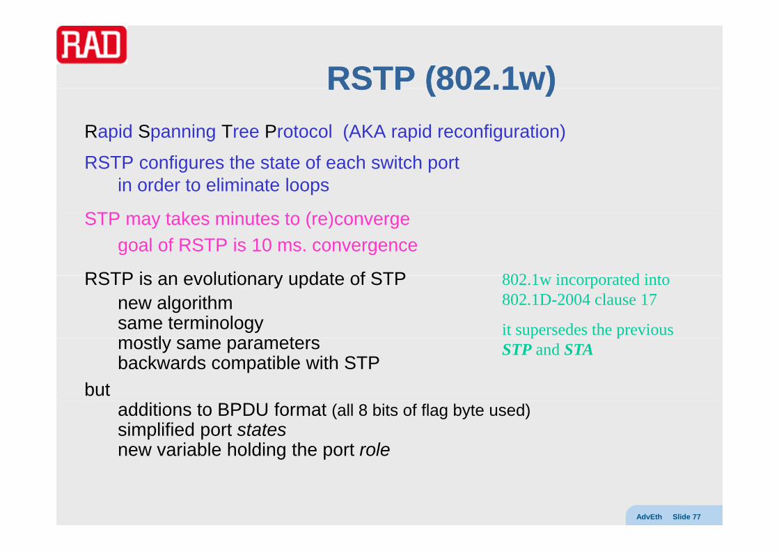
RSTP (RSTP (802802..11w)w)RSTP (RSTP (802802..11w)w)Rapid Spanning Tree Protocol (AKA rapid reconfiguration)
RSTP configures the state of each switch portin order to eliminate loops
STP t k i t t ( )STP may takes minutes to (re)convergegoal of RSTP is 10 ms. convergence
RSTP is an evolutionary update of STP 802 1 i t d i tRSTP is an evolutionary update of STPnew algorithmsame terminology
tl t
802.1w incorporated into 802.1D-2004 clause 17
it supersedes the previous mostly same parametersbackwards compatible with STP
but
p pSTP and STA
additions to BPDU format (all 8 bits of flag byte used)simplified port statesnew variable holding the port role
AdvEth Slide 77

RSTP states and rolesRSTP states and rolesRSTP states and rolesRSTP states and rolesThe 802.1D concept of port state includes both
forwarding state (blocks or forwards traffic) and topology role (root port, designated port).
802.1w decouples the concepts
802 1D h 5 t t t 802 1 h l 3802.1D has 5 port states 802.1w has only 3disabledblocking discardingli t ilisteninglearning learningforwarding forwarding802.1D defines a concept of port role, but has no matching variable
Spanning Tree Algorithm determines role based on BPDUs 802 1w defines 4 port roles802.1w defines 4 port roles
rootdesignatedbackup
AdvEth Slide 78
backupalternate
multiple spanning treesmultiple spanning trees 802802..11ssmultiple spanning trees multiple spanning trees 802802..11ss
conventionally, all VLANs use the same spanning treeconventionally, all VLANs use the same spanning tree (even if IVL switches use different FIDs)
so links blocked by STP will never carry any traffic
we can utilize these links if different VLANs could use different spanning treesif different VLANs could use different spanning trees
Multiple Spanning Tree Protocol - 1998 amendment to 802.1Q th t l d l ith i 802 1Q 2003 l 13 d 14the protocol and algorithm are now in 802.1Q-2003 clauses 13 and 14
MSTP configures a separate spanning tree for each VLAN blocks redundant links separately for each spanning tree
Cisco has its own Per VLAN Spanning Tree (PVST and PVST+) protocols
AdvEth Slide 79

RbridgesRbridges (IETF TRILL WG)(IETF TRILL WG)Rbridges Rbridges (IETF TRILL WG)(IETF TRILL WG)
Spanning tree is a clean protocol - needs no configuration
but STP converges slowly
and may make inefficient treeshosts that are actually close become far aparthosts that are actually close become far apart
we could use IP routing protocolsbut that requires allocating IP addresses, etc.
A new solution TRansparent Interconnection of Lots of Links
defines a combination of router and bridge called an Rbridgedefines a combination of router and bridge called an Rbridgethat run a link state protocol (e.g. OSPF, IS-IS)
Rbridges have the advantages of both with the disadvantages of neitherRbridges have the advantages of both with the disadvantages of neither
optimized paths but no configuration
AdvEth Slide 80
gno IP layer

AlgorhymeAlgorhymeAlgorhymeAlgorhyme
I think that I shall never see a graph more lovely than a tree.
A tree whose crucial property is loop free connectivityis loop-free connectivity.
A tree that must be sure to span so packet can reach every LAN. p y
First, the root must be selected. by ID, it is elected.
Least-cost paths from root are traced. in the tree, these paths are placed.
A mesh is made by folks like meA mesh is made by folks like me, then bridges find a spanning tree.
R di P l
AdvEth Slide 81
Radia Perlman

Algorhyme vAlgorhyme v22Algorhyme vAlgorhyme v22
I hope that we shall one day seeI hope that we shall one day seea graph more lovely than a tree.
A graph to boost efficiencyhil till fi ti fwhile still configuration-free.
A network where RBridges canroute packets to their target LAN.route packets to their target LAN.
The paths they find, to our elation,are least cost paths to destination.
With packet hop counts we now see,the network need not be loop-free.
RBridges work transparentlyRBridges work transparently.without a common spanning tree.
Ray Perlner
AdvEth Slide 82

QoS AspectsQoS AspectsQoS AspectsQoS Aspects
Flow control (PAUSE frames)
handling QoS
prioritization (802.1p)
MEF service attributes
AdvEth Slide 83

Flow controlFlow controlFlow controlFlow control
When an Ethernet switch receives traffic faster than it can process itp
it needs to tell its immediate neighbor(s) to slow down
O h lf d l li k th b k b l dOn half-duplex links the back pressure can be employedoverloaded device jams the shared media by sending preambles or idle frames detected by other devices as collisions causing senders to wait (CSMA/CD)
On full-duplex point-to-point links, PAUSE frames are sent
Since they are sent on a point to point link the DA is unimportantSince they are sent on a point-to-point link, the DA is unimportant, and the standard multicast address 01-80-C2-00-00-01 is used making the PAUSE frame easy to recognize
The PAUSE frame encodes the requested pause period as a 2-byte unsigned integer representing units of 512 bit times
AdvEth Slide 84

Handling QoSHandling QoSHandling QoSHandling QoSEthernet switches have FIFO buffers
h t' i t d t toutput
output
output
on each port's input and output
But prioritization may be needed
t port 1
t port 2
t port 3
so output buffers may be divided into multiple queues
outgoing frames put into queues of specified priority switchfabric
switchfabric
we could base priority on input port
fabricfabric
but then for the next switch to know the priority toowe would need to send to its appropriate port too
so the number of both input and output ports
input por
input por
input porso the number of both input and output portswould be multiplied by the number of priority levels!
a better way is to mark the frames
rt 1
rt 2
rt 3
AdvEth Slide 85
a better way is to mark the frames

802802..11pp802802..11p p
the VLAN tag reserves a 3 bit user priority field AKA P-bitsthe VLAN tag reserves a 3 bit user priority field AKA P bits
P-bits allow marking individual frames with a value 0 … 7
non-VLAN frames can use priority tagging (VLAN=0)non VLAN frames can use priority tagging (VLAN 0)
just to have a user priority field
user priority levels map to traffic classes (CoS)
traffic class indicates drop probability, latency across the switch, etc.but there are no BW/latency/jitter guaranteesbut there are no BW/latency/jitter guarantees
P=0 means non-expedited traffic
802.1Q recommends mappings from P-bits to traffic class
l t f RPR t ffi l d i it
AdvEth Slide 86
see later for RPR traffic classes and priority

(MEF) Service attributes(MEF) Service attributes(MEF) Service attributes(MEF) Service attributesall per EVC, per CoS
frame lossfraction of frames that should be delivered that actually are deliveredspecified by T (time interval) and L (loss objective)specified by T (time interval) and L (loss objective)
frame delaymeasured UNI-N to UNI-N on delivered framesspecified by T, P (percentage) and D (delay objective)
f d l i iframe delay variationspecified by T, P, L (difference in arrival times), V (FDV objective)
BW profiles per EVC, per CoS, per UNI
AdvEth Slide 87
specified by CIR, CBS, EIR, EBS, …

Burst size token bucketsBurst size token bucketsBurst size token bucketsBurst size token bucketsthe profile is enforced in the following waythere are two byte buckets C of size CBS and E of size EBSthere are two byte buckets, C of size CBS and E of size EBStokens are added to the buckets at rate CIR/8 and EIR/8when bucket overflows tokens are lost (use it or lose it)
if ingress frame length < number of tokens in C bucket
frame is green and its length in tokens is debited from C bucketl if i f l h b f k i E b kelse if ingress frame length < number of tokens in E bucket
frame is yellow and its length of tokens is debited from E bucketelse frame is redelse frame is red
green frames are delivered and service objectives apply
CBSEBS
yellow frames are delivered by service objectives don’t applyred frames are discarded C E
AdvEth Slide 88

Hierarchical BW profilesHierarchical BW profilesHierarchical BW profilesHierarchical BW profilesMEF 10.1 allows bandwidth profile
per UNI (can be different at different UNIs of same multipoint EVC)p ( p )per EVC and CoS
but doesn’t allow a single frame to be subject to more than 1 profile
N k i th MEF i i d t ll iNew work in the MEF is aimed at allowingper CoS bandwidth profile, followed byper EVC color-aware profile
The idea is to allow the user to use excess “paid for” bandwidth for lower priority traffic (BW sharing)
Thusframes will never be downgraded (green yellow or yellow red) couplingin
g(green yellow, or yellow red)frames may be upgraded (red yellow, yellow green)
shar
iThere are complex inter-relationships
between sharing and couplingAdvEth Slide 89

Link aggregationLink aggregationLink aggregationLink aggregation
Link aggregation (ex 802.3ad, 802.3 clause 43)
Link Aggregation Control Protocol (LACP)Link Aggregation Control Protocol (LACP)
conversations
AdvEth Slide 90

Link Aggregation task forceLink Aggregation task forceLink Aggregation task forceLink Aggregation task forceEthernet needed “link aggregation”
(AKA bonding Ethernet trunk inverse mux NIC teaming etc)(AKA bonding, Ethernet trunk, inverse mux, NIC teaming, etc)
enables bonding several ports together as single uplinkincreased uplink BW can exceed 1 Gb/s (or now 10Gb/s)increased uplink BW can exceed 1 Gb/s (or now 10Gb/s)common practice to install multiple fibers/cablesincrementally grow uplink capacity– needn’t purchase new expensive Gb switch when exceed 100 Mbneedn t purchase new expensive Gb switch when exceed 100 Mb
increased availability continue at reduced rate when 1 link failsneedn’t constrain peak capacity of individual ports
Link Aggregation 802.3ad task forcePAR approved June 1998WG ballot Nov 1999LMSC ballot Nov 1999standard Feb 2000folded into 802.3-2000 as clause 43
AdvEth Slide 91
Alternative inverse MUX defined by EFM task force (EFM bonding)

Link aggregation in actionLink aggregation in actionLink aggregation in actionLink aggregation in actionLink Aggregation Group controlled by aggregatoraggregation port looks standard Ethernet MAC (no SN, etc.)
MAC address may be one that of one of the linksonly for p2p full duplex operationthe aggregator = frame distributor + frame collector + parser + multiplexer
di t ib t f t li k ki LAGdistributes frames to links making up LAGcollects frames from LAG and passes to clients
link aggregation should not cause misordering, replication, etc.gg g g p
binding of ports to LAGs distributed via Link Aggregation Control ProtocolLACP uses slow protocol frameslinks may be dynamically added/removed from LAGoptional marker protocol provides sequence markers
AdvEth Slide 92

LALA conversationsconversationsLA LA conversationsconversationsframe distributor assigns all frames from a conversation to one linkg
a conversation is defined as frames with same:SADADA reception portprotocol (Ethertype)higher layer protocol (LC info)higher layer protocol (LC info)
hash on above maps to port
before moving conversation to a different link, be o e o g co e sat o to a d e e t ,ensure that all transmitted frames have been received (marker protocol)
LACP continuously monitors to detect if changes needed
AdvEth Slide 93
Ethernet protectionEthernet protectionEthernet protectionEthernet protection
Linear protection
Ring protectionRing protection
Y(J)S APS Slide 94

APSAPSAPSAPSAutomatic Protection Switching (APS)
is a functionality of carrier-grade transport networksis often called resilience
since it enables service to quickly recover from failuressince it enables service to quickly recover from failuresis required to ensure high reliability and availability
APS includes :detection of failures (signal fail or signal degrade) on a working channel
switching traffic transmission to a protection channel
selecting traffic reception from the protection channel
(optionally) reverting back to the working channel once failure is repaired(optionally) reverting back to the working channel once failure is repaired
Y(J)S APS Slide 95

Using STP and LAGUsing STP and LAGUsing STP and LAGUsing STP and LAGSTP and RSTP automatically converge to a loop-free topology
RSTP converges in about the same time as STPbut can reconverge after a topology change in less than 1 second
Thus RSTP can be used as a protection mechanismThus RSTP can be used as a protection mechanismHowever, the switching time will be many tens of ms to 100s of ms
LAG also detects failures (using physical layer or LACP) and automatically removes failed links
Thus LAG too can be used as a primitive protection mechanism
When used this way it is called worker/standby or N+N modeWhen used this way it is called worker/standby or N N mode
The restoration time will be on the order of 1 second
Y(J)S APS Slide 96

G.G.80318031G.G.80318031Q9 of SG15 in the ITU-T is responsible for protection switching
In 2006 it produced G.8031 Linear Ethernet Protection Switching
G.8031 uses standard Ethernet formats, but is incompatible with STP
The standard addresses point-to-point VLAN connectionsSNC (local) protection classSNC (local) protection class1+1 and 1:1 protection typesunidirectional and bidirectional switching for 1+1bidirectional switching for 1:1bidirectional switching for 1:1revertive and nonrevertive modes1-phase signaling protocol
G.8031 uses Y.1731 OAM CCM messages in order to detect failures
G.8031 defines a new OAM opcode (39) for APS signaling messages
Y(J)S APS Slide 97
Switching times should be under 50 ms (only holdoff timers when groups)
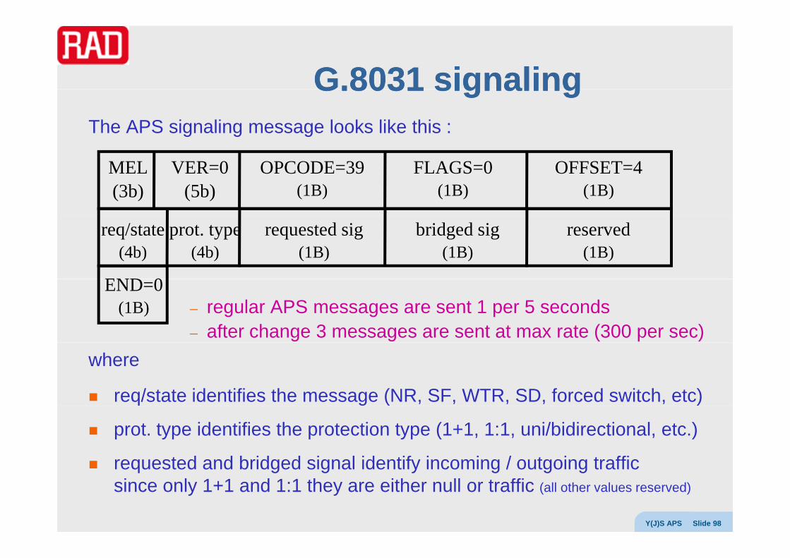
G.G.80318031 signalingsignalingG.G.8031 8031 signalingsignalingThe APS signaling message looks like this :
MEL(3b)
VER=0(5b)
OPCODE=39(1B)
FLAGS=0(1B)
OFFSET=4(1B)
req/state(4b)
prot. type(4b)
requested sig(1B)
bridged sig(1B)
reserved(1B)
END 0– regular APS messages are sent 1 per 5 seconds– after change 3 messages are sent at max rate (300 per sec)
END=0(1B)
where
req/state identifies the message (NR, SF, WTR, SD, forced switch, etc)
prot. type identifies the protection type (1+1, 1:1, uni/bidirectional, etc.)
requested and bridged signal identify incoming / outgoing traffic
Y(J)S APS Slide 98
requested and bridged signal identify incoming / outgoing traffic since only 1+1 and 1:1 they are either null or traffic (all other values reserved)

G.G.8031 18031 1::11 revertiverevertive operationoperationG.G.8031 18031 1::1 1 revertiverevertive operationoperationIn the normal (NR) state :
head-end and tail-end exchange CCM (at 300 per second rate)g ( p )on both working and protection channelshead-end and tail-end exchange NR APS messageson the protection channel (every 5 seconds)
When a failure appears in the working channeltail-end stops receiving 3 CCM messages on working channeltail-end enters SF statetail-end enters SF statetail-end sends 3 SF messages at 300 per second on the APS channeltail-end switches selector (bi-d and bridge) to the protection channelhead-end (receiving SF) switches bridge (bi-d and selector) to protection channelhead-end (receiving SF) switches bridge (bi-d and selector) to protection channeltail-end continues sending SF messages every 5 secondshead-end sends NR messages but with bridged=normal
Wh h f il i l dWhen the failure is clearedtail-end leaves SF state and enters WTR state (typically 5 minutes, 5..12 min)tail-end sends WTR message to head-end (in nonrevertive - DNR message)t il d d WTR 5 d
Y(J)S APS Slide 99
tail-end sends WTR every 5 secondswhen WTR expires both sides enter NR state

Ethernet rings ?Ethernet rings ?Ethernet rings ?Ethernet rings ?Ethernet has become carrier grade :
deterministic connection-oriented forwardingOAMsynchronizationy
The only thing missing to completely replace SDH is ring protection
However, Ethernet and ring architectures don’t go togetherHowever, Ethernet and ring architectures don t go togetherEthernet has no TTL, so looped traffic will loop foreverSTP builds trees out of any architecture – no loops allowed
There are two ways to make an Ethernet ringopen loop– cut the ring by blocking some linkg y g– when protection is required - block the failed link closed loop
di bl STP (b t id i fi it l i !)
Y(J)S APS Slide 100
– disable STP (but avoid infinite loops in some way !)– when protection is required - steer and/or wrap traffic

Ethernet ring protocolsEthernet ring protocolsEthernet ring protocolsEthernet ring protocols
Open loop methodsp pG.8032 (ERPS)rSTP (ex 802.1w)RFER (RAD)RFER (RAD)ERP (NSN)RRST (based on RSTP)REP (Cisco)REP (Cisco)RRSTP (Alcatel)RRPP (Huawei)EAPS (E t RFC 3619)EAPS (Extreme, RFC 3619)EPSR (Allied Telesis)PSR (Overture)
Closed loop methodsRPR (IEEE 802.17)
Y(J)S APS Slide 101
CLEER and NERT (RAD)
G.G.80328032G.G.80328032Q9 of SG15 produced G.8032 between 2006 and 2008
G.8032 is similar to G.8031strives for 50 ms protection (< 1200 km, < 16 nodes)
but here this number is deceiving as MAC table is flushed– but here this number is deceiving as MAC table is flushedstandard Ethernet format but incompatible with STPuses Y.1731 CCM for failure detection
l Y 1731 t i f R APS i li ( d 40)employs Y.1731 extension for R-APS signaling (opcode=40)R-APS message format similar to APS of G.8031(but between every 2 nodes and to MAC address 01-19-A7-00-00-01)revertive and nonrevertive operation defined
However, G.8032 is more complex due torequirement to avoid loop creation under any circumstancesneed to localize failures need to maintain consistency between all nodes on ring
Y(J)S APS Slide 102
need to maintain consistency between all nodes on ringexistence of a special node (RPL owner)

RPLRPLRPLRPL
G.8032 defines the Ring Protection Link (RPL)g ( )as the link to be blocked (to avoid closing the loop) in NR state
One of the 2 nodes connected to the RPL is designated the RPL owner
Unlike RAD’s RFER th i l RPLthere is only one RPL ownerthe RPL and owner are designated before setupoperation is usually revertive
All ring nodes are simultaneously in 1 of 2 modes – idle or protectingin idle mode the RPL is blocked in protecting mode the failed link is blocked and RPL is unblockedin protecting mode the failed link is blocked and RPL is unblockedin revertive operationonce the failure is cleared the block link is unblocked
d th RPL i bl k d i
Y(J)S APS Slide 103
and the RPL is blocked again

G.G.80328032 revertiverevertive operationoperationG.G.8032 8032 revertiverevertive operationoperationIn the idle state :
adjacent nodes exchange CCM at 300 per second rate (including over RPL)j g p ( g )exchange NR RB (RPL Blocked) messages in dedicated VLAN every 5 seconds (but not over RPL)R-APS messages are never forwarded
When a failure appears between 2 nodesnode(s) missing CCM messages peek twice with holdoff timenode(s) block failed link and flush MAC tablenode(s) block failed link and flush MAC tablenode(s) send SF message (3 times @ max rate, then every 5 sec)node receiving SF message will check priority and unblock any blocked linknode receiving SF message will send SF message to its other neighbornode receiving SF message will send SF message to its other neighborin stable protecting state SF messages over every unblocked link
When the failure is clearedd ( ) d t t CCM d t t d ti (bl k ti R APS )node(s) detect CCM and start guard timer (blocks acting on R-APS messages)
node(s) send NR messages to neighbors (3 times @ max rate, then every 5 sec)RPL owner receiving NR starts WTR timerwhen WTR expires RPL owner blocks RPL flushes table and sends NR RB
Y(J)S APS Slide 104
when WTR expires RPL owner blocks RPL, flushes table, and sends NR RBnode receiving NR RB flushes table, unblocks any blocked ports, sends NR RB

G.G.80328032--20102010After coming out with G.8032 in 2008 (G.8032v1)
the ITU came out with G.8032-2010 (G.8032v2) in 2010( )
This new version is not backwards-compatible with v1but a v2 node must support v1 as well (but then operation is according to v1)
Major differences :2 designated nodes – RPL owner and RPL nodesignificant changes to – state machine– priority logicpriority logic– commands (forced/manual/clear) and protocol
new Wait To Block timersupports more general topologies (sub-rings)– ladders (For Further Study in v1)– multi-ring
ring subringsubring
gring topology discoveryvirtual channel based on VLAN or MAC address
Y(J)S APS Slide 105
ladder

EFMEFMEFM EFM
Ethernet in the First Mile (ex-802.3ah)
EFM bondingEFM bonding
xDSL (2M and 10M)
P2P opticsP2P optics
P2MP optics (EPON)
EFM OAMEFM OAM
AdvEth Slide 106

EFM task forceEFM task forceEFM task forceEFM task forcein IEEE new works starts with a Call For Interestafter which a Study Group is formed to consider a new projectafter which a Study Group is formed to consider a new projectSG was formed in Nov. 2000 to think about Ethernet in the First Milethe next step is defining a Project Authorization Requestp g j qPAR is approved if it passes the 5 criteria1. Broad market potential2 Compatibility2. Compatibility3. Distinct identity4. Technical feasibility5 Economic feasibility5. Economic feasibilityEFM PAR was approved in Sept 2001a task force or task group in a WG works on a specific projectg p p p jit receives a name of the form WG.unique_charsthe EFM task force was called 802.3ah
AdvEth Slide 107

EFM task forceEFM task force (cont.)(cont.)EFM task force EFM task force (cont.)(cont.)
a task force reviews proposalsa task force reviews proposals
and then produces and refines drafts
when complete the draft goes to WG ballot (need 75%)p g G ( 5%)
EFM went to WG ballot in July 2003
after WG ballot, sponsor ballot (75%), p ( )
and then LMSC Standards Body approval
EFM became full standard in June 2004
after approval the standard is published
1 year later available free of chargey g
it is usually combined with the WG standard at its next revision
EFM was folded into 802.3-2005
AdvEth Slide 108

EFMEFMEFMEFM
the 802.3ah task force had 4 tracks:
…
OAM (57)
LLC (802.2)
the 802.3ah task force had 4 tracks:
Copper (now in clause 61)– 10PASS-TS (10M, 750m) (now in clause 62) MAC
MP MAC (64)
OAM (57)
( , ) ( )– 2BASE-TL (2M, 2.7km) (now in clause 63)– PME aggregation (now in subclause 61.2.2)
reconciliation
MAC
MIIOptics – 100M (now in clause 58)
1G ( i l 59 60)
PCS (61)
TC (G.993.1)
MII
– 1G (now in clauses 59, 60)– EPON (now in clause 65 see GPON/GEPON course)
P2MP clause 64
( )
PMA (62/63)
PMD P2MP clause 64– logic to enable EPON (see GPON/GEPON course)
OAM (see OAM section below) clause 57
(58/59/60/62/63)
AdvEth Slide 109
( )PCS = Physical Coding SublayerTC = Transmission ConvergencePMA = Physical Medium AttachmentPMD = Physical Medium Dependent

EFM bondingEFM bonding (PME Aggregation)(PME Aggregation)EFM bonding EFM bonding (PME Aggregation)(PME Aggregation)
Physical Medium Entity inverse MUX (EFM bonding)Defined in 802 3 2005 61 2 2 and ITU T G 998 2 (ITU T allows for ADSL as well)Defined in 802.3-2005 61.2.2 and ITU-T G.998.2 (ITU-T allows for ADSL as well)
Optional feature applicable only to copper EFM (DSL) linksPME Aggregation Function (PAF) is part of PCS (between MII and TC)PME Aggregation Function (PAF) is part of PCS (between MII and TC)
fragments Ethernet frame forms non-Ethernet fragments (16b header + fragment)
Di id f t h i l li k ( h i i i l t ti d d t)Divides fragments over physical links (mechanism is implementation dependent)
Uses 14-bit sequence number to recover order of fragmentsFragments can be from 64 to 512 bytes in length (all multiple of 4 except EOP)Fragments can be from 64 to 512 bytes in length (all multiple of 4 except EOP)
Fragments delineated by TC layer framing (64/65 octet coding – not HDLC)
Can compensate for prate ratios up to 4differential delay up to 15,000 bit times(delay is due to modem interleaving and rate differences)(delay is due to modem interleaving and rate differences)
AdvEth Slide 110

PME AggregationPME Aggregation (cont.)(cont.)PME Aggregation PME Aggregation (cont.)(cont.)
IPG preamble SFD Ethernet frame IPGIPG preamble SFD Ethernet frame IPGthe Ethernet frame from DA SA to FCS is fragmented
h d f t 1 h d f t 5CRCheader fragment 1 header fragment 5 …
header fragment 2 header fragment 6 …
CRC
CRC
PME 1
PME 2 g g
header fragment 3 header fragment 7 …CRCPME 3
mechanism for choosing fragment size and order is implementation dependent
header fragment 4 header fragment 8 …CRCPME n
CRC is 16 bits for VDSL 32 bits for SHDSL with polynomials defined in 802.3 61.3.3.3
Fragmentation header :
AdvEth Slide 111
sequence number (14b)
EOP (1b)
SOP (1b)

RPRRPR –– 802802..1717RPR RPR 802802..1717
Resilient Packet Rings
resilience and fairness requirements
MAC operation
topology discovery
AdvEth Slide 112

RPRRPR –– 802802..1717RPR RPR 802802..1717Resilient Packet Rings
are compatible with standard Ethernetare compatible with standard Ethernetare robust (lossless, <50ms protection, OAM)are fair (based on client throttling)
t Q S (3 l A B C)support QoS (3 classes – A, B, C)are efficient (full spatial reuse)are plug and play (automatic station autodiscovery)
ringlet0
extend use of existing fiber rings
counter-rotating add/drop ringlets, running ringlet1g p g , gSONET/SDH (any rate, PoS, GFP or LAPS) or “packetPHY” (1 or 10 Gb/s ETH PHY)
ringlet1
developed by 802.17 WGbased on Cisco’s Spatial Reuse Protocol (RFC 2892)
AdvEth Slide 113
p ( )

Why rings?Why rings?Why rings?Why rings?conventional Ethernet topologies are
point to point bus starpoint-to-point bus star
while conventional SONET/SDH topologies are rings
advantages of ring topologiesprotectionfairnesssimple multicast support
RPR mechanisms– input shaping– ringlet selection
AdvEth Slide 114
ringlet selection– buffer insertion– transit buffer(s)

Basic queuingBasic queuing
traffic going around ring traffic for local sink
AC B
g g gplaced into internal bufferin dual-transit queue mode
placed into 1 of 2 buffers
traffic for local sinkplaced in output buffer
according to service class
according to service classsent according to fairness
PTQ
STQ
traffic from local source
AC B
fairnessPrimary/Secondary Transit Queue
AdvEth Slide 115
sourcesent according to fairnessfirst sent to ringlet selection

RPR service classesRPR service classesRPR service classesRPR service classesRPR defines 3 main classes
class A : real time (low latency/FDV)class A : real time (low latency/FDV)class B : near real time (bounded predictable latency/FDV)class C : best effort
class use info rate D/FDV FE
A0 RT reserved low No
A1 RT allocated low NoA1 RT allocated,
reclaimable
low No
B-CIR near RT allocated, bounded NoB CIR near RT ,
reclaimableNo
B-EIR near RT opportunistic unbounded Yes
AdvEth Slide 116
C BE opportunistic unbounded Yes

Class useClass useClass useClass useA0 ring BW is reserved – not reclaimed even if no traffic
in dual-transit queue mode:class A frames from the ring are queued in PTQclass B, C in STQ
priority for egressframes in PTQ local class A frameslocal class B (when no frames in PTQ)frames in STQlocal class C (when no PTQ, STQ, local A or B)
Notes:class A have minimal delayclass B have higher priority than STQ transit frames, so bounded delay/FDVclasses B and C share STQ, so once in ring have similar delay
AdvEth Slide 117

RPRRPR -- fairnessfairnessRPR RPR fairnessfairness
8M4M2M1M
1M 2M 4M 8M 16M
regular Ethernet is inherently unfair!
RPR ne er discards packets to resol e congestionRPR never discards packets to resolve congestioninstead uses ingress policing
an upstream node can potentially starve a downstream nodean upstream node can potentially starve a downstream nodewhen a downstream node experiences BW starvation
it sends a fairness request upstream
AdvEth Slide 118
upstream node MUST reduce its traffic injection rate

RPRRPR -- protectionprotectionRPR RPR protectionprotection
rings give inherent protection against single point of failurerings give inherent protection against single point of failure
RPR specifies 2 mechanismssteering s ee gwrapping (optional)
(implementations may also do wrapping then steering)(implementations may also do wrapping then steering)
steering info
wrap
steering info
AdvEth Slide 119
wrap

Twice as efficient as EoS ?Twice as efficient as EoS ?Twice as efficient as EoS ?Twice as efficient as EoS ?it is frequently said that RPR is twice as efficient as EoShow could that be true?RPR has inherent spatial re-useslots in SONET/SDH rings are typically not re-used
due to management complexity
slot used BW dused
AdvEth Slide 120
data remains in slot –removed by originator
BW reused
RPRRPR -- multicastmulticastRPR RPR multicastmulticast
for regular Ethernet multicast requires replicating frames
for RPR, broadcast/flooding/multicasti l i t i f f isimply requires not removing frame from ring
multicast can be unidirectional or bidirectional
when TTL=0 the frame is finally removedwhen TTL=0 the frame is finally removed
AdvEth Slide 121

RPR frame formatsRPR frame formatsRPR frame formatsRPR frame formats802.17 defines 4 frame types:
data frameETH MAC frame + TTL, frame type and flag fields
t l fcontrol frameattribute discovery, topology, protection, round-trip measure, OAM, etc.
fairness framefairness framesent upstream to indicate required fair rate
idle frameidle framesent to neighboring node to avoid PTQ overflow due to lack of sync
AdvEth Slide 122
Ethernet OAMEthernet OAMEthernet OAMEthernet OAM
OAM functionsOAM functions
link OAM (802.3ah)
service OAM (Y 1731 802 1ag)service OAM (Y.1731, 802.1ag)
AdvEth Slide 123

OAMOAMOAMOAManalog channels and 64 kbps digital channels
did not have mechanisms to check signal validity and qualitydid not have mechanisms to check signal validity and qualitythus
major faults could go undetected for long periods of timeh d t h t i d l li f lt h t dhard to characterize and localize faults when reportedminor defects might be unnoticed indefinitely
as PDH networks evolved, more and more overhead was dedicated to,Operations, Administration and Maintenance (OAM) functions
including:it i f lid i lmonitoring for valid signal
defect reporting alarm indication/inhibition
when SONET/SDH was designed overhead was reserved for OAM functions
t d i id i l t OAM l ti
AdvEth Slide 124
today service providers require complete OAM solutions

OAMOAM (cont.)(cont.)OAM OAM (cont.)(cont.)OAM is a user-plane function
but may influence control and management plane operationsbut may influence control and management plane operationsfor example
OAM may trigger protection switching, but doesn’t switchOAM d t t i i d li k b t d ’t i i thOAM may detect provisioned links, but doesn’t provision them
OAM is more complex and more critical for PSNs
since in addition to previous problems loss of signalbit errorsbit errors
we have new defect typespackets may be lostypackets may be delayedpackets may incorrectly delivered
OAM requirements are different for CO and CL modes
AdvEth Slide 125
OAM requirements are different for CO and CL modes

ITUITU--T concept T concept -- TrailTrailppsince OAM is critical to proper network functioning
OAM must be added to the concept of a connectiona trail is defined as a connection along with integrity supervision
clients gain access to the trail at access points (AP)
the trail termination function is responsible for generating / processing OAM
=AP APtrail
TCP TCP
AdvEth Slide 126

Trail Termination FunctionsTrail Termination FunctionsTrail Termination FunctionsTrail Termination Functionswhat functionality does the trail termination function add ?
Continuity Check (e.g. LOS, periodic CC packets)Connectivity Verification (detect misrouting)signal quality monitoring (e.g. error detection coding)g q y g ( g g)defect notification/alarm inhibition (AIS(FDI), RDI(BDI))
source termination functions:t h k dgenerates error check code (FEC, CRC, etc)
returns remote indications (REI, RDI)inserts trail trace identification information
sink termination functions:detects misconnectionsdetects loss of signal loss of framing AIS instead of signal etcdetects loss of signal, loss of framing, AIS instead of signal, etc.detects code violations and/or bit errorsmonitors performance
AdvEth Slide 127

Defects, Faults, etc.Defects, Faults, etc.Defects, Faults, etc.Defects, Faults, etc.G.806 defines:
l ( ) ll t b bl dianomaly (n): smallest observable discrepancy between desired and actual characteristics
defect (d): density of anomalies that interrupts some required functionfault cause (c): root cause behind multiple defectsfault cause (c): root cause behind multiple defectsfailure (f): persistent fault cause - ability to perform function is terminatedaction (a): action requested due to fault cause
f ( ) fperformance parameter (p): calculatable value representing ability to function
for example: equipment specifications define relationshipspdLOS = loss of signal defectcPLM = payload mismatch causeaAIS = insertion of AIS action
equipment specifications define relationshipse.g. aAIS <= dAIS or dLOS or dLOF
alarms are human observable failure indications
AdvEth Slide 128

Supervision FlowchartSupervision Flowchart
performanceit i
statisticsth i
pX
anomaly
monitoring gathering
nXy
defectcorrelation
persistencemonitoring
fXcX
defect filter dX
consequentaction
aXN.B. this is a greatly simplified picture
AdvEth Slide 129
more generally there are external signals, time constants, etc.

Ethernet OAM functionalityEthernet OAM functionalityEthernet OAM functionalityEthernet OAM functionality
Continuity Check / Connectivity VerificationContinuity Check / Connectivity Verification
LoopBacks – in-service (nonintrusive)– in-service (nonintrusive) – out-of service (intrusive)– linktrace
defect notification / alarm inhibition– AIS (FDI)– RDI (BDI)– RDI (BDI)
performance monitoringframe loss– frame loss
– one-way delay– round-trip delay– delay variation
AdvEth Slide 130
– delay variation– throughput

Two flavorsTwo flavorsTwo flavorsTwo flavors
for many years there was no OAM for Ethernetnow there are two incompatible ones!now there are two incompatible ones!
Link layer OAM – EFM 802.3ah 802.3 clause 57single link onlysingle link onlylimited functionality
Service OAM – Y.1731, 802.1ag (CFM)any network configurationfull OAM functionality
in some cases ma need to r n both ( ETH ETY)in some cases may need to run both (e.g. ETH over ETY)while in others only service OAM makes sense
AdvEth Slide 131

EFM OAMEFM OAMEFM OAMEFM OAMEFM networks are mostly p2p links or p2mp PONs
thus a link layer OAM is sufficient for EFM applicationsthus a link layer OAM is sufficient for EFM applicationsSince EFM link is between customer and Service Provider
EFM OAM entities are classified as active (SP) or passive (customer)active entity can place passive one into LB mode but not the reverseactive entity can place passive one into LB mode, but not the reverse
but link OAM may be used for any Ethernet link, not just EFM ones
EFM OAMPDUs are a slow protocol frames not forwarded by bridgesEFM OAMPDUs are a slow protocol frames – not forwarded by bridges
Ethertype = 88-09 and subtype 03messages multicast to slow protocol specific group addressOAMPDUs must be sent once per second (heartbeat)messages are TLV-based
DA01-80-C2-
SATYPE
8809
SUBTYPE
03
FLAGS(2B)
CODE(1B) DATA CRC
AdvEth Slide 132
00-00-02 8809 03

EFM OAM capabilitiesEFM OAM capabilitiesEFM OAM capabilitiesEFM OAM capabilities
6 codes are definedInformation (autodiscovery, heartbeat, fault notification)Event notification (statistics reporting)Variable request (active entity query passive’s configuration) (not really OAM)a ab e equest (act e e t ty que y pass e s co gu at o ) ( ot ea y O )Variable response (passive entity responds to query) (not really OAM)Loopback control (active entity enable/disable of passive’s PHY LB mode)Organization specific (proprietary extensions)g p (p p y )
flags are in every OAMPDUexpedite notification of critical eventsexpedite notification of critical events – link fault (RDI)– dying gasp
ifi d– unspecifiedmonitor slowly degradations in performance
AdvEth Slide 133

Y.Y.17311731 OAMOAMY.Y.1731 1731 OAMOAMSPs want to monitor full networks, not just single links
Service layer OAM provides end-to-end integrity of the Ethernet service over arbitrary server layersy y
Ethernet is the hardest case for OAM
connectionless – can’t use ATM-like connection continuity checkMP2MP – so need full connectivity verificationlayering – need separate OAM for operator, SPs, customerspecific ETH behaviors – flooding, multicast, etc.
AdvEth Slide 134

Y.Y.17311731 messagesmessagesY.Y.1731 1731 messagesmessages
Y 1731 supports many OAM message types:Y.1731 supports many OAM message types:
Continuity Check proactive heartbeat with 7 possible rates
L B k i t/ lti t i ith ti l ttLoopBack unicast/multicast pings with optional patternsLink Trace identify path taken to detect failures and loopsAIS periodically sent when CC fails, useful when no STPyRDI LoCK signal inform peer entity about intentional diagnostic actionsTest signal in service/out of service tests for loss rate etcTest signal in-service/out-of-service tests for loss rate, etc.Automatic Protection SwitchingMaintenance Communications Channel remote maintenanceEXPerimentalVendor SPecific
AdvEth Slide 135

Y.Y.17311731 frame formatframe formatY.Y.1731 1731 frame formatframe formatafter DA, SA and Ethertype (8902)
Y.1731/802.1ag PDUs have the following header (may be VLAN tagged)
LEVEL OPCODEVER FLAGS TLV OFFLEVEL(3b)
OPCODE(1B)
VER(5b)
FLAGS(1B)
TLV-OFF(1B)
if there are sequence numbers/timestamp(s), they immediately follow
th TLV th “ d TLV” f ll d b th CRCthen come TLVs, the “end TLV”, followed by the CRC
TLVs have 1B type and 2B length fields
there may or not be a value fieldthe “end-TLV” has type = zero and no length or value fields
AdvEth Slide 136

MEPs and MIPsMEPs and MIPsMEPs and MIPsMEPs and MIPsMaintenance Entity (ME) – entity that requires maintenanceME is a relationship between ME end pointsp pbecause Ethernet is MP2MP, we need to define a ME GroupMEGs can be nested, but not overlappedMEG LEVEL takes a value 0 … 7by default - 0,1,2 operator, 3,4 SP, 5,6,7 customerMEP = MEG end point (MEG = ME group ME = Maintenance Entity)MEP = MEG end point (MEG = ME group, ME = Maintenance Entity)
(in IEEE MEG MA = Maintenance Association)unique MEG IDs specify to which MEG we send the OAM messageMEPs responsible for OAM messages not leaking out
but transparently transfer OAM messages of higher levelMIPs = MEG Intermediate PointsMIPs = MEG Intermediate Points
never originate OAM messages, process some OAM messagestransparently transfer others
AdvEth Slide 137
transparently transfer others

MEPs and MIPsMEPs and MIPs (cont.)(cont.)MEPs and MIPs MEPs and MIPs (cont.)(cont.)
AdvEth Slide 138

Ethernet securityEthernet securityEthernet securityEthernet security
Security functions
802.1X
MACsec (802.1AE)
MACkey (802.1af)
AdvEth Slide 139

Security functionsSecurity functionsSecurity functionsSecurity functions
Some threats that may need to be countered in Ethernet networksdenial of service (DoS) to all or some stationstheft of servicetheft of serviceaccess to confidential informationmodification of informationcontrol of restricted resourcescontrol of restricted resources
Some security functions that solve some of these problemsth ti tisource authentication
confidentialitydata integrityreplay protectionnon-repudiationblocking DoS attacks
AdvEth Slide 140
gprotection against traffic analysis

802802..11XX802802..11XX
802.1X is a port-based access control mechanismpit enables or blocks traffic from a port
It provides authentication for devices wishing to communicate
It is based on the Extensible Authentication Protocol (RFC3748)
It is used in 802.11i for WiFi (WPA2)
In 802.1X there are three entities :the authenticatort e aut e t catothe supplicantthe authentication server (usually a RADIUS server)
802.1X PDUs use EtherType 88-8E and multicast address 01-80-C2-00-00-03
AdvEth Slide 141

802802..11X operationX operation802802..11X operationX operation
Upon detection of a new supplicantp ppthe authenticator’s switch port is set to unauthorizedonly 802.1X traffic is allowed
The authenticator sends EAP-Request identity to the supplicant
The supplicant responds with EAP-response
The authenticator forwards response to the authenticating (RADIUS) server
If the server accepts the request the authenticator sets the port to the "authorized" mode traffic from supplicant is allowed in
AdvEth Slide 142

MACsecMACsecMACsecMACsec802.1AE was approved in June 2006based on well known AES-128 encryptionbased on well known AES 128 encryption
but with a new mode - Galois Counter ModeMain features
k C ti l t k b f iworks over Connectionless network by forming secure associationsintegrated into Ethernet frame formatgkey management and association establishment outside scope
802 1AE MACsec provides802.1AE MACsec providesorigin authenticationconfidentiality
ti l d t i t itconnectionless data integrityreplay protectionlimited blocking of DoS attacks
AdvEth Slide 143
but may lower some QoS attributes (e.g. introduces bounded delay)

MACsec formatMACsec formatMACsec formatMACsec format
DA SA Type payload FCS
DA SA d t FCS’S TAG ICVDA SA secure data FCS’SecTAG (incl. IV) ICV
optionalconfidentiality
SecTAG contains
integrity
MACsec Ethertype (88E5)4B Packet Number (sequence number)8B Secure Channel Identifier 12 B Initialization Vector
…
AdvEth Slide 144

AES/GCM advantagesAES/GCM advantagesAES/GCM advantagesAES/GCM advantagesencryption is provided by “state-of-the-art” AES (128/256 bit keys)
mode of operation uses a counter to thwart replay attacks
Integrity Check Value verifies the payload integrity
encryption, integrity, and source authentication by a single algorithm
authentication can be performed without encrypting
data not in packet payload (e g source identifiers) can be authenticated toodata not in packet payload (e.g. source identifiers) can be authenticated too
Initialization Vector nonce can be any length (but should not repeat for given key)
algorithm can be efficiently implemented in softwarealgorithm can be efficiently implemented in software
computation can be parallelized for high speed hardware implementations
unencumbered by IPR claims
adopted by IEEE 802.1ae for MACsec and RFCs 4106 and 4543 for IPsec
AdvEth Slide 145

AES/GCM Input / OutputAES/GCM Input / OutputAES/GCM Input / OutputAES/GCM Input / OutputEncryption Input
( 236 32 )plaintext to be encrypted (up to 236-32 bytes)encryption key (128 or 256 bits)per-packet randomly generated IV (12 B recommended)additional data to be authenticated but not encrypted (0 2^61 B)additional data to be authenticated but not encrypted (0 .. 2 61 B)
Encryption Outputciphertext (length = length of plaintext)ICV (16 B)ICV (16 B)
Decryption Inputciphertextciphertextencryption keyIV used for encryptionICV generated by encryption
Encryption OutputAuthentication pass/failif pass - plaintext
AdvEth Slide 146
p p
802802..11afaf802802..11afafMACsec peers need to share encryption keys
keys need to be regularly updated
MACkey (802 1af) is a key distribution protocolMACkey (802.1af) is a key distribution protocolprovides authenticated distribution of keys needed by MACsec
C f CMACkey defines MAC Key Distribution Protocol Data Units MKDPDUs
Authentication based on Extensible Authentication Protocol (RFC 3748)( C 3 8)uses a centrally administered Authentication Server MACkey defines EAP encapsulation over LANs (EAPOL)
AdvEth Slide 147
OtherOther 802802 security documentssecurity documentsOther Other 802 802 security documentssecurity documents802.1AR - Secure Device IdentityExtends 802 1X specifying unique per device identifiers (DevID)Extends 802.1X specifying unique per-device identifiers (DevID)Management and binding of a device to its identifiers
802.11i Enhanced WiFi securityWiFi's Wired Equivalent Privacy encryption broken by Biham (Technion)802 11i (WPA2) amendment approved June 2004802.11i (WPA2) amendment approved June 2004Uses 802.1X/EAP and AES block cipher
802.10 Enhanced WiFi securityFormer 802 security protocol (approved 1998)y p ( pp )Had security associations, key management, confidentiality, integrityUsed by Cisco’s Inter Switch Link (ISL) protocolWithdrawn (Jan 2004) due to lack of use
AdvEth Slide 148
Withdrawn (Jan 2004) due to lack of use

Synchronous EthernetSynchronous EthernetSynchronous EthernetSynchronous Ethernet
synchronizing networks
packet time protocols
synchronous Ethernet physical layer
AdvEth Slide 149

Synchronizing networksSynchronizing networksSynchronizing networksSynchronizing networksSONET/SDH/PDH/TDM networks require highly accurate timingin every such network there is a primary reference clockin every such network there is a primary reference clockall other clocks derive timing from the PRCthe clock signal is carried in the physical layer
we can say that such networks distribute data + timing
applications needing accurate timing get it “free”applications needing accurate timing get it freecellular base stationselectric power facilitiesdata/modem terminalsTDMoIP GWshigh quality audio/video systemshigh quality audio/video systems
PSNs such as Ethernet have no physical layer clock
AdvEth Slide 150
and thus do not natively distribute timinghow can we support applications needing timing?

Packet time protocolsPacket time protocolsPacket time protocolsPacket time protocols
TDM t k di t ib t t f b t t ll l kTDM networks distribute accurate frequency but not wall-clockRAD has developed methods for adaptive frequency recovery
for TDMoIP applicationsfor TDMoIP applications
There are packet-based protocols for timing distribution, e.g., IETF NTP ( UDP/IP)IETF NTP (over UDP/IP)IEEE 1588 (over UDP/IP or pure Ethernet)
both are based on time servers that send timestampsboth are based on time servers that send timestampsusually frequency is acquired first, then ranging, then calibration
NTP and 1588 can be used for frequency distributionNTP and 1588 can be used for frequency distributionpresent versions are not sufficiently accurate for all applications1588 can exploit Transparent Clocks and Boundary Clocks
AdvEth Slide 151

SynchronousSynchronous Ethernet (Ethernet (SyncESyncE))Synchronous Synchronous Ethernet (Ethernet (SyncESyncE))
Ethernet started as a CSMA/CD bursty LAN technologyEthernet started as a CSMA/CD bursty LAN technologyreceiver acquired the transmitter clock by locking onto preamble
But for all continuously transmitting full duplex ETY layerswe can lock clocks based on PHY layer
then synchronous Ethernet distributes clock just like TDM networks
This requires modifications to the Ethernet PHYThis requires modifications to the Ethernet PHY but no other changes to network
S E i t ith h Eth tSyncE can co-exist with nonsynchronous Ethernetand makes IEEE 1588 wall-clock distribution work even better!
AdvEth Slide 152

ESMCESMCESMCESMCSynchronous network devices need to identify their clock qualityy y q y
This is traditionally done using Synchronization Status Messages
G 8264 defines an Ethernet Synchronization Messaging ChannelG.8264 defines an Ethernet Synchronization Messaging Channel
ESMC frames are slow protocol frames ith th ITU’ OUI (0 0019A7)– with the ITU’s OUI (0x0019A7)
– and a new slow protocol subtype 0x0A
The frames carry a 4-bit SSM codeThis code can contain any of the usual SSM values (PRC, SSU, SEC, …)
or one of 2 new values defined for SyncE interfacesor one of 2 new values defined for SyncE interfaces
AdvEth Slide 153