advances in neutron radiography and tomographyxrsi.cmit.csiro.au/tomowkshop/pdfs/banhart.pdf · aus...
TRANSCRIPT
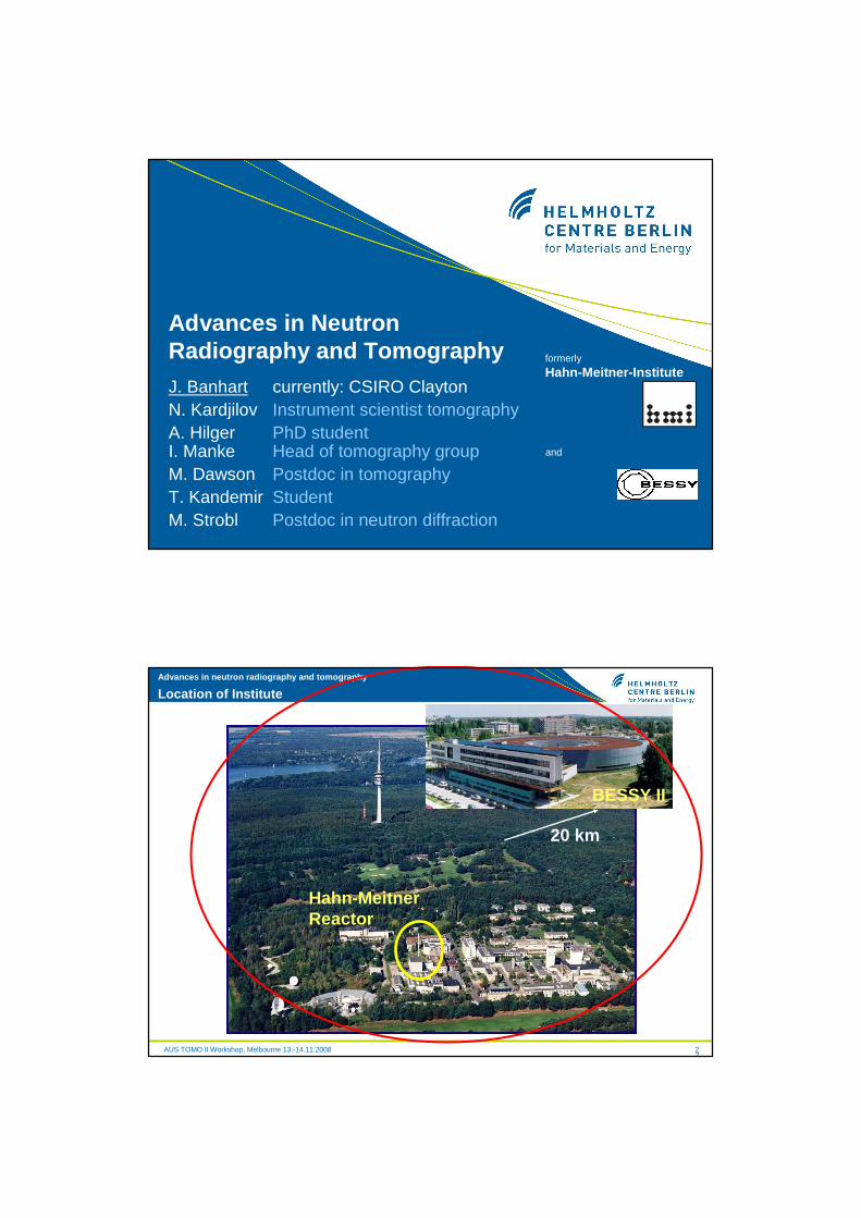
formerly
Hahn-Meitner-Institute
and
Advances in NeutronRadiography and TomographyJ. Banhart currently: CSIRO ClaytonN. Kardjilov Instrument scientist tomographyA. Hilger PhD studentI. Manke Head of tomography groupM. Dawson Postdoc in tomographyT. Kandemir StudentM. Strobl Postdoc in neutron diffraction
AUS TOMO II Workshop, Melbourne 13.-14.11.2008
Advances in neutron radiography and tomography
22
Hahn-MeitnerReactor
20 km
BESSY II
Location of Institute

AUS TOMO II Workshop, Melbourne 13.-14.11.2008
Advances in neutron radiography and tomography
3
Application Centre Tomographic Methods
Neutron tomography
X-ray tomography and microscopy
2 µm
Focused Ion Beam-Tomography
14x14x253nm3
3D atom probe
40 nm
Electron tomography
1 m10 mm0,1 mm1 µm10 nm1Å
AUS TOMO II Workshop, Melbourne 13.-14.11.2008
Advances in neutron radiography and tomography
4
Contents
� Neutron absorption imaging� principles� optimisation of beam and detection system
� Applications� fuel cell, combustion chamber, spark plug,
cellular materials, battery
� Alternative contrast mechanisms� energy scanning � (phase contrast and dark field imaging)� use of polarised neutrons

AUS TOMO II Workshop, Melbourne 13.-14.11.2008
Advances in neutron radiography and tomography
5
X-ray radiography
AUS TOMO II Workshop, Melbourne 13.-14.11.2008
Advances in neutron radiography and tomography
6
Neutron radiography in early days
Taken from C.O. Fischer’s article in WCNR-4
Berlin, 1935 – 1938H. Kallmann & Kuhn with Ra-Be neutron generator
Berlin, until Dec. 1944O. Peter with anaccelerator neutron source
More sophisticated programs with neutrons after WW II at the research reactor in Harwell (UK)
Comparison between X-ray and neutron images: valves , manometers, injectors
Renewed interest since about 1995
AUS TOMO II Workshop, Melbourne 13.-14.11.2008
Advances in neutron radiography and tomography
7
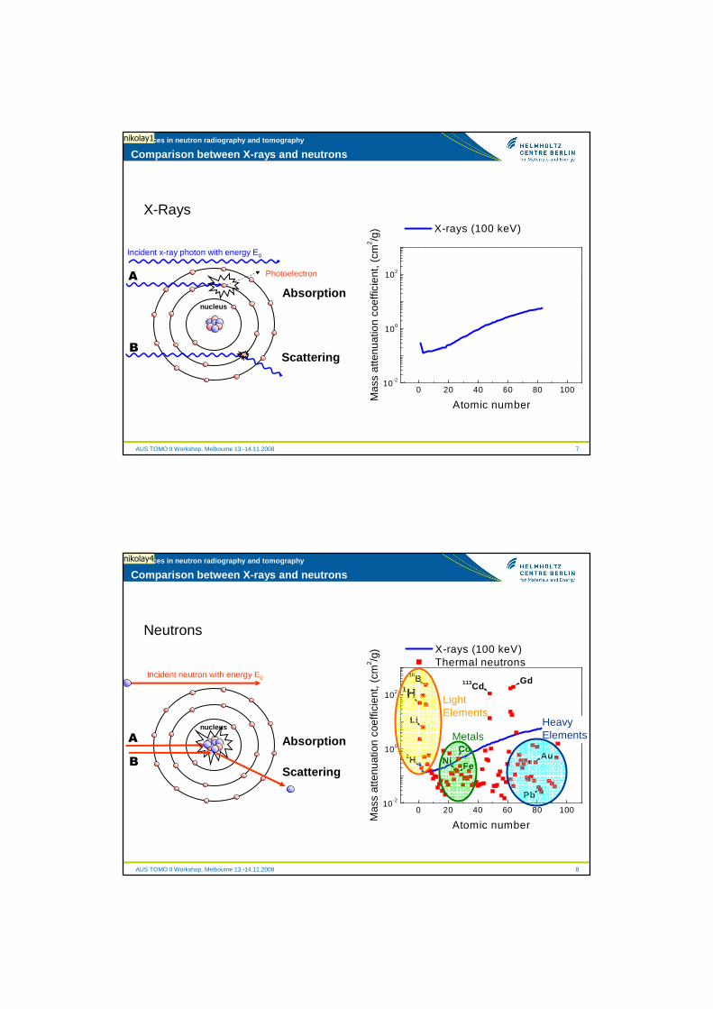
Comparison between X-rays and neutrons
X-Rays
A
B
Photoelectron
Absorption
Incident x-ray photon with energy E0
Scattering
0 20 40 60 80 10010-2
100
102
Mas
s at
tenu
atio
n co
effic
ient
, (cm
2 /g)
Atomic number
X-rays (100 keV)
nucleus
nikolay1
AUS TOMO II Workshop, Melbourne 13.-14.11.2008
Advances in neutron radiography and tomography
8
Comparison between X-rays and neutrons
Neutrons
A
B
Absorption
Incident neutron with energy E0
Scattering
nucleus
0 20 40 60 80 10010-2
100
102
Fe
Mas
s at
tenu
atio
n co
effic
ient
, (cm
2 /g)
Atomic number
X-rays (100 keV) Thermal neutrons
Gd113Cd10B
Li
2H
1H
CoNi
Pb
Au
LightElements
MetalsHeavyElements
nikolay4

Slide 7
nikolay1 Kardjilov, 29/05/2005
Slide 8
nikolay4 Kardjilov, 29/05/2005

AUS TOMO II Workshop, Melbourne 13.-14.11.2008
Advances in neutron radiography and tomography
9
Contrast
Resolution
• given by beam characteristics• often limited by detector
• given by neutron interaction with matter
Contrast and Resolution
AUS TOMO II Workshop, Melbourne 13.-14.11.2008
Advances in neutron radiography and tomography
10
Neutron imaging - contrast
Neutrons: hydrogen-containing parts appear dark, metal light grey
X-rays: thicker metallic components are hard to penetrate, hydrogen-containing parts hardly visible
AUS TOMO II Workshop, Melbourne 13.-14.11.2008
Advances in neutron radiography and tomography
11
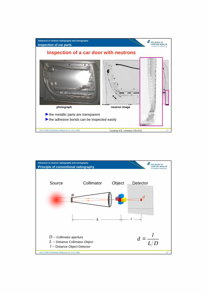
Inspection of a car door with neutrons
►the metallic parts are transparent
►the adhesive bonds can be inspected easily
photograph neutron image
Inspection of car parts
Courtesy of E. Lehmann, PSI (CH)
AUS TOMO II Workshop, Melbourne 13.-14.11.2008
Advances in neutron radiography and tomography
12
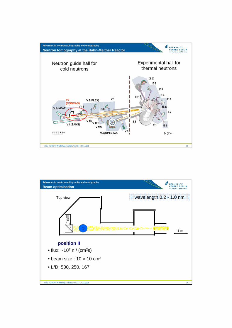
Principle of conventional radiography
d
ld
L D=
L l
D
L – Distance Collimator-Object
l – Distance Object-Detector
D – Collimator aperture
Source Collimator DetectorObject

AUS TOMO II Workshop, Melbourne 13.-14.11.2008
Advances in neutron radiography and tomography
13
Resolution: dependence on l
3,5" floppy drive images with l = 0 cm 10 cm and 20 cm distance,detection: film + Gd sandwich, cold neutron guide with L/D=71.
B. Schillinger, FRM-I
increasing l
AUS TOMO II Workshop, Melbourne 13.-14.11.2008
Advances in neutron radiography and tomography
14
Resolution: dependence on L/D
L/D=71 L/D=115 L/D=320 L/D>500
increasing L/D
B. Schillinger, FRM-I
But: higher L/D implies lower flux and longer exposition time
Neutron radiographs of a small engine
AUS TOMO II Workshop, Melbourne 13.-14.11.2008
Advances in neutron radiography and tomography
15
Neutron tomography at the Hahn-Meitner Reactor
V7 (CONRAD)
Experimental hall forthermal neutrons
Neutron guide hall forcold neutrons
AUS TOMO II Workshop, Melbourne 13.-14.11.2008
Advances in neutron radiography and tomography
16
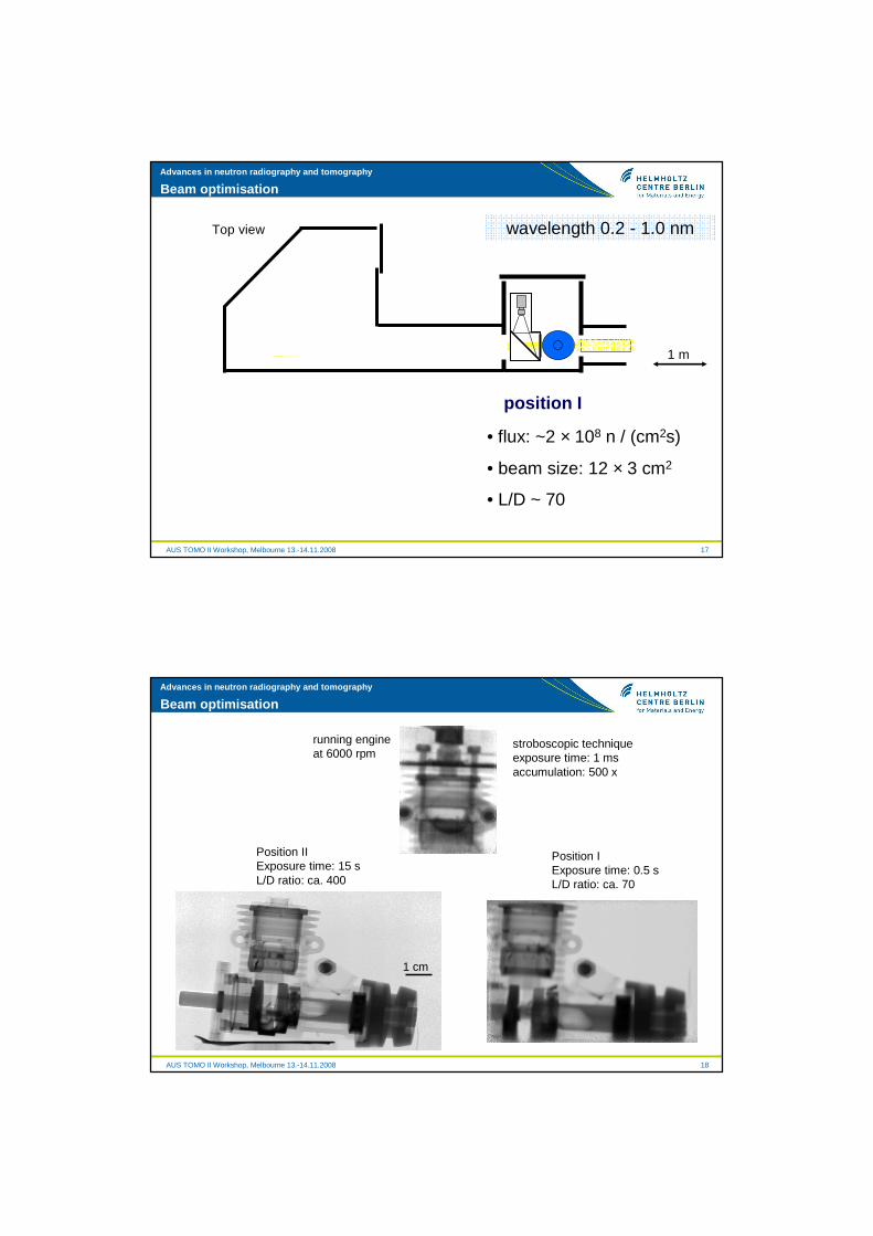
position II
Beam optimisation
• flux: ~107 n / (cm2s)
• beam size : 10 × 10 cm2
• L/D: 500, 250, 167
wavelength 0.2 - 1.0 nm
1 m
Top view
AUS TOMO II Workshop, Melbourne 13.-14.11.2008
Advances in neutron radiography and tomography
17
position I
Beam optimisation
• flux: ~2 × 10⁸ n / (cm2s)
• beam size: 12 × 3 cm2
• L/D ~ 70
wavelength 0.2 - 1.0 nm
1 m
Top view
AUS TOMO II Workshop, Melbourne 13.-14.11.2008
Advances in neutron radiography and tomography
18
position Iposition II
Beam optimisation
• flux: ~107 n / (cm2s)
• beam size : 10 × 10 cm2
• L/D: 500, 250, 167
Position II Exposure time: 15 sL/D ratio: ca. 400
1 cm
running engineat 6000 rpm
stroboscopic techniqueexposure time: 1 msaccumulation: 500 x
Position IExposure time: 0.5 sL/D ratio: ca. 70

AUS TOMO II Workshop, Melbourne 13.-14.11.2008
Advances in neutron radiography and tomography
1919
500 400 300 200 100 µm
Standard setup Improved lenses + Improved screenScintillator: 200 µm 6LiFLens system: 50 mmPixel size: 100 µmExposure time: 20 s
Scintillator: 200 µm 6LiFLens system: 105 mmPixel size: 30 µmExposure time: 20 s
Scintillator: 5 µm GadoxLens system: 105 mmPixel size: 30 µmExposure time: 120 s
100 µm
60 µm
Detector optimisation – qualitative estimation
AUS TOMO II Workshop, Melbourne 13.-14.11.2008
Advances in neutron radiography and tomography
20
6Li+ZnS 400 1926Li+ZnS 200 1376Li+ZnS 100 1086Li+ZnS 50 72Gadox 30 76Gadox 20 58Gadox 10 52Gadox 5 48
Gadox 30 61Gadox 20 33Gadox 10 27Gadox 5 25
Scintillatormaterial
Spatial resolution [μm]
Scintillatorthickness [μm]
105 mm lens
200 mm lens
Detector optimisation
FOV : 60 x 60 mm2
FOV : 27 x 27 mm2

AUS TOMO II Workshop, Melbourne 13.-14.11.2008
Advances in neutron radiography and tomography
21
Comparison X-ray / neutrons
Microfocus X-ray scanner
Pixel size: 23 µm
Flat panel
Cold neutrons
Pixel size: 30 µm
Lens: 105 mm
Scintillating screen: 10µm Gadox
1 cm
AUS TOMO II Workshop, Melbourne 13.-14.11.2008
Advances in neutron radiography and tomography
22
Fuel cells
Polymer electrolyte fuel cell
• Nafion membrane
• carbon fibre Gas Diff. Layer
• typ. 100 cells in a stack

AUS TOMO II Workshop, Melbourne 13.-14.11.2008
Advances in neutron radiography and tomography
23
In-situ neutron radiography: fuel cells
neutron radiography (fast motion)
operating fuel cell applying realistic power profilesPEM fuel cell
14 cm L/D 167, ~ 108 n/cm 2s, ∆∆∆∆T = 10 s
liquid water accumulation ⇒ gas flow in the channels hinderedwater management: a major challenge for PEM fuel cells
AUS TOMO II Workshop, Melbourne 13.-14.11.2008
Advances in neutron radiography and tomography
Fuel cell: neutron tomogram of stopped triple-stack cell

AUS TOMO II Workshop, Melbourne 13.-14.11.2008
Advances in neutron radiography and tomography
Fuel cell: neutron tomogram of water in flowfield channe ls
I. Manke, C. Hartnig, N. Kardjilov, A. Hilger, J. B anhart et alQuasi-in situ neutron tomography on polymer electrolyte membrane fuel cell stacksApplied Physics Letters 90, 184101 (2007)
AUS TOMO II Workshop, Melbourne 13.-14.11.2008
Advances in neutron radiography and tomography
26
Neutron tomography: fuel sediments in combustion ch amber
2 cm
Fuel sediments

AUS TOMO II Workshop, Melbourne 13.-14.11.2008
Advances in neutron radiography and tomography
27
X-ray tomographyNeutron tomography
Glue between spheres Steel hollow spheres
Complementarity of neutrons and X-rays
AUS TOMO II Workshop, Melbourne 13.-14.11.2008
Advances in neutron radiography and tomography
28
Neutron tomography X-ray tomography
Highly absorbing regions: hydride remnants?
Complementarity of neutrons and X-rays

AUS TOMO II Workshop, Melbourne 13.-14.11.2008
Advances in neutron radiography and tomography
29
Partially dischargedca. 1,3V
Fully charged1,6V
Examples: battery discharge
Neutrontomography
X-raytomography
KOH, H2O
Steel container
H+I. Manke et al., Appl. Phys. Lett.90, 214102 (2007)
AUS TOMO II Workshop, Melbourne 13.-14.11.2008
Advances in neutron radiography and tomography
30
Beam monochromatisation
polychromaticbeam
monochromaticbeam
Double crystal monochromator: PCG crystals (mosaicity of 0.8°)
Range: 2.0 – 6.5 Å
Band width (∆λ/λ): ~ 3%
Neutron flux: ~ 4x10⁵ n/cm2s (at λ=3.0 Å)
Beam size: 5 x 20 cm2

AUS TOMO II Workshop, Melbourne 13.-14.11.2008
Advances in neutron radiography and tomography
31
Coherent scattering – Bragg edges
dhkl
2dhklsinθ=λpolychromatic neutron beam
polycrystallinematerial
Bragg‘s law
DCM
λ
2 θ
AUS TOMO II Workshop, Melbourne 13.-14.11.2008
Advances in neutron radiography and tomography
32
polychromatic neutron beam
DCM
λ
Coherent scattering – Bragg edges
2dhklsin90°=λdhkl
2dhkl=λ (110)
polycrystallinematerial
Bragg‘s law
Cross-sections of iron per atom

AUS TOMO II Workshop, Melbourne 13.-14.11.2008
Advances in neutron radiography and tomography
33
Energy scanning radiography
Welded joint (photo)
3.8 Å 4.0 Å 4.2 Å
1 cm *Collaboration work with PSI, Switzerland
2 3 4 5 6 70.4
0.6
0.8
1.0
1.2
1.4
1.6
1.8
2.0
Atte
nuat
ion
coef
ficie
nt, Σ
[cm
-1]
Wavelength [Å]
Fe (110)
AUS TOMO II Workshop, Melbourne 13.-14.11.2008
Advances in neutron radiography and tomography
34
2 3 4 5 6 70.4
0.6
0.8
1.0
1.2
1.4
1.6
1.8
2.0
Atte
nuat
ion
coef
ficie
nt, Σ
[cm
-1]
Wavelength [Å]
Fe
θ
θ
ββββhkl
dhkl
−=
hklhkl d2
arcsin2
λπβ
(110)
2 4 6
-2
0
2
Wavelength [Å]
Data: Derivative1_Eisen0059GModel: GaussEquation: y=y0 + (A/(w*sqrt(PI/2)))*exp(-2*((x-xc)/w)^2)Weighting: y No weighting Chi^2/DoF = 0.24436R^2 = 0.5796 y0 0.2702 ±0.07067xc 4.00941 ±0.02468w 0.31818 ±0.05082A -1.03499 ±0.15132
Derivative of Eisen0059_G Gauss fit of Derivative1_Eisen0059G
Energy scanning radiography
AUS TOMO II Workshop, Melbourne 13.-14.11.2008
Advances in neutron radiography and tomography
35
Quantitative texture analysis
35
AUS TOMO II Workshop, Melbourne 13.-14.11.2008
Advances in neutron radiography and tomography
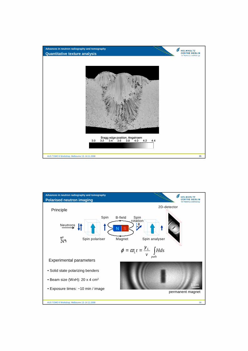
36
Neutrons
Spin polariser Spin analyser
2D-detector
Spin
Magnet
B-field
N Sϕ
Spinrotation
x
y
z
Neutrons
Spin polariser Spin analyser
2D-detector
Spin
Magnet
B-field
N Sϕ
Spinrotation
x
y
z
Polarised neutron imaging
Principle
Experimental parameters
• Solid state polarizing benders
• Beam size (WxH): 20 x 4 cm2
• Exposure times: ~10 min / image
∫==path
LL Hds
vt
γωϕ
1 cm
permanent magnet

AUS TOMO II Workshop, Melbourne 13.-14.11.2008
Advances in neutron radiography and tomography
37
Neutrons
Spin polariser Spin analyser
2D-detector
Spin
Magnet
B-field
N Sϕ
Spinrotation
x
y
z
Neutrons
Spin polariser Spin analyser
2D-detector
Spin
Magnet
B-field
N Sϕ
Spinrotation
x
y
z
Polarised neutron imaging
Principle
Experimental parameters
• Solid state polarazing benders
• Beam size (WxH): 20 x 4 cm2
• Exposure times: ~10 min / image
Al slab
AUS TOMO II Workshop, Melbourne 13.-14.11.2008
Advances in neutron radiography and tomography
38
Neutrons
Spin polariser Spin analyser
2D-detector
Spin
Magnet
B-field
N Sϕ
Spinrotation
x
y
z
Neutrons
Spin polariser Spin analyser
2D-detector
Spin
Magnet
B-field
N Sϕ
Spinrotation
x
y
z
Polarised neutron imaging
Principle
Experimental parameters
• Solid state polarazing benders
• Beam size (WxH): 20 x 4 cm2
• Exposure times: ~10 min / image 1 cm
non-dipole magnets
Al slab

AUS TOMO II Workshop, Melbourne 13.-14.11.2008
Advances in neutron radiography and tomography
39
Polarised neutron tomography
7.0 K
7.2 K
6.9 K
1 cm
Pb cylinder(polycrystalline)
T
7.196 K (Tc)
7.0 K
Example: Flux Trapping
Tomographyrotation
axis
trappedflux
N. Kardjilov, I. Manke, M. Strobl, A. Hilger, W. Treimer, Th. Krist, M. Meissner, J. Banhart, Nature Physics 4, 399-403 (2008)
AUS TOMO II Workshop, Melbourne 13.-14.11.2008
Advances in neutron radiography and tomography
40
Access to neutron tomography instrument CONRAD
� http://www.hmi.de/bensc/
� Next proposal deadlines: 15th March and 15th September 2009
� Online proposal submission: https://www.hmi.de/pubbin/bensc_club.pl
2005/I 2005/II 2006/I 2006/II 2007/I 2007/II 2008/I 2008/II 2009/I0.0
0.5
1.0
1.5
2.0
Load
fact
or fo
r ex
tern
al p
ropo
sals
Load factor for the neutron imaging beamline CONRAD at HZB

AUS TOMO II Workshop, Melbourne 13.-14.11.2008
Advances in neutron radiography and tomography
AUS TOMO II Workshop, Melbourne 13.-14.11.2008 41
1. Some Mathematical Concepts for Tomographic Reconstruction
2. Visualisation, Processing and Analysis of Tomographic Data
3. Radiation Sources and Interaction of Radiation with Matter
4. Synchrotron X-ray Absorption Tomography
5. Phase Contrast and Holographic Tomography
6. Tomography using magnifying optics7. Scanning X-ray Tomography8. Three-dimensional X-ray Diffraction
(3DXRD)9. Detectors for Synchrotron Tomography10. Fundamentals of Electron Tomography11. Applications of Electron Tomography12. Neutron Absorption Tomography13. Neutron Phase Contrast and Polarised
Neutron Tomography14. Neutron Refraction and Small-Angle
Scattering Tomography
AUS TOMO II Workshop, Melbourne 13.-14.11.2008
Advances in neutron radiography and tomography
42
Thank you !Further questions and discussions?
→ [email protected] (until 03/09)→ [email protected] (after 04/09)