advances in optical engineering for future telescopes
TRANSCRIPT
DOI: 10.29026/oea.2021.210040
Advances in optical engineering for futuretelescopesDaewook Kim1,2,3*, Heejoo Choi1,3, Trenton Brendel1, Henry Quach1,Marcos Esparza1, Hyukmo Kang1, Yi-Ting Feng1, Jaren N. Ashcraft1,Xiaolong Ke4, Tianyi Wang5 and Ewan S. Douglas2
Significant optical engineering advances at the University of Arizona are being made for design, fabrication, and con-struction of next generation astronomical telescopes. This summary review paper focuses on the technological ad-vances in three key areas. First is the optical fabrication technique used for constructing next-generation telescope mir-rors. Advances in ground-based telescope control and instrumentation comprise the second area of development. Thisincludes active alignment of the laser truss-based Large Binocular Telescope (LBT) prime focus camera, the new MOBI-US modular cross-dispersion spectroscopy unit used at the prime focal plane of the LBT, and topological pupil segmentoptimization. Lastly, future space telescope concepts and enabling technologies are discussed. Among these, theNautilus space observatory requires challenging alignment of segmented multi-order diffractive elements. The OASISterahertz space telescope presents unique challenges for characterizing the inflatable primary mirror, and the Hyperionspace telescope pushes the limits of high spectral resolution, far-UV spectroscopy. The Coronagraphic Debris and Exo-planet Exploring Pioneer (CDEEP) is a Small Satellite (SmallSat) mission concept for high-contrast imaging of circums-tellar disks and exoplanets using vector vortex coronagraph. These advances in optical engineering technologies willhelp mankind to probe, explore, and understand the scientific beauty of our universe.
Keywords: computer controlled optical surfacing; CCOS multiplexing; dwell time optimization; optical metrology; telescope alignment; large binocular telescope; MOBIUS; pupil segmentation; OASIS; nautilus; hyperion; CDEEP; vectorvortex coronagraph
Kim D, Choi H, Brendel T, Quach H, Esparza M et al. Advances in optical engineering for future telescopes. Opto-Electron Adv 4,210040 (2021).
IntroductionAstronomical advances are largely coupled with techno-logical improvements. From the invention of the first op-tical telescope used by Galileo in 1609 and through theforeseeable future, astronomy and optical engineering
are forever linked. In this paper, several advances aresummarized that will enable future telescopes to probeand expand our scientific understanding of the universe.
To begin, Section Deterministic computer controlledoptical surfacing technologies covers optical fabrication
1Wyant College of Optical Sciences, University of Arizona, 1630 E. University Blvd., Tucson, AZ 85721, USA; 2Department of Astronomy and
Steward Observatory, University of Arizona, 933 N. Cherry Ave., Tucson, AZ 85721, USA; 3Large Binocular Telescope Observatory, University of
Arizona, 933 N. Cherry Ave., Tucson, AZ 85721, USA; 4School of Mechanical and Automotive Engineering, Xiamen University of Technology,
Xiamen 361024, China; 5National Synchrotron Light Source II (NSLS-II), Brookhaven National Laboratory, PO Box 5000, Upton, New York
11973, USA.*Correspondence: D Kim, E-mail: [email protected]: 29 March 2021; Accepted: 20 May 2021; Published: 20 June 2021
Opto-Electronic Advances
Review2021, Vol. 4, No. 6
Open Access This article is licensed under a Creative Commons Attribution 4.0 International License.To view a copy of this license, visit http://creativecommons.org/licenses/by/4.0/.
© The Author(s) 2021. Published by Institute of Optics and Electronics, Chinese Academy of Sciences.
210040-1
and manufacturing process optimization technologies.Fabrication of large optics is an extremely time-consumingprocess due to the large size and high-accuracy require-ments1−4. For example, polishing each segment of the Gi-ant Magellan Telescope (GMT) to the specified accuracyconsumed about one year. Modern precision optical sur-faces are manufactured with Computer Controlled Op-tical Surfacing (CCOS) processes5−7, such as small-toolpolishing5,7, bonnet polishing8, magnetorheological fin-ishing, ion beam figuring9,10, etc. With these systems,there are two main categories of methods for improvingpolishing efficiency: increasing the material removal rateand minimizing the total dwell time. In this section, bothcategories are addressed. The mathematical theory ofmultiplexed two CCOS runs for simultaneous use of twopolishing tools has been developed6. Dwell time optimiz-ation is demonstrated via Robust Iterative Fourier Trans-form-based dwell time Algorithm (RIFTA)9. These emer-ging technologies provide opportunity to increase speedand reduce cost of large optics manufacturing.
Section Very large telescope control system, instru-ment, and segmentation summarizes optical engineeringtechnology developments for very large telescopes. As afirst example, the Large Binocular Telescope (LBT) teamis developing a laser-truss based alignment system formaintaining telescope collimation and pointing11,12. Thelaser truss metrology system, able to measure the relativeposition of optics in six degrees of freedom, is the first ofits kind to be implemented on large, ground-based tele-scopes. A second innovation for the LBT system is an in-strument package referred to as MOBIUS (Mask-Ori-ented Breadboard Implementation for UnscramblingSpectra). The MOBIUS system adds cross-dispersioncapability to the existing LUCI (LBT Utility Camera inthe Infrared) near infrared (NIR) imagers and spectro-graphs13. By inserting the MOBIUS module, we extendsimultaneous coverage down to 0.32 μm by binocularobservations with one MODS (The Multi-Object DoubleSpectrographs) and one LUCI. The final example dis-cussed in Section Very large telescope control system, in-strument, and segmentation is segmentation of primarymirror apertures. A pinwheel aperture segmentation is apromising approach which obtains a point spread func-tion (PSF) with enhanced axial symmetry. This ismodeled using Fraunhofer diffraction theory with thePython-based POPPY simulation tool14.
Section Future space telescope concepts and enabling
technologies introduces some next generation space tele-scope concepts. The multi-order diffractive engineered(MODE) lens is a novel optical element that is light-weight, achromatic across a large spectrum and has morerelaxed tolerances than mirror segments of a similarsize15−19. The Nautilus Space Observatory conceptprovides a new solution utilizing the transmissiveMODE lens segments. Our group has developed both amechanism to align MODE lens segments20 and an in-process metrology system to monitor the lens alignmentwhile the segments are being bonded together21. The Or-biting Astronomical Satellite for Investigating Stellar Sys-tems (OASIS) is a proposed terahertz space observatorythat will explore the role of water in the evolution ofplanetary systems and features a 20-meter diameterprimary mirror, which is obtained by using inflatablemembrane technology19,22−24. By pressurizing one trans-parent and one metallized membrane sealed around a ri-gid tensioning ring, a lenticular surface with immenselight-collecting power can be obtained. We present ametrology technique for measuring the surface figure ofsuch novel inflatable mirrors24. At the other end of theoptical spectrum, the next generation UV space tele-scope concept, Hyperion, is designed to examine the ori-gin of the star formation25,26. At the atomic-to-molecularinterstellar boundary layer, the fuel for star formation(SF) exists in a state of H2. Both the reflective telescopeand cross-dispersion instrumentation design using free-form optics are presented. The Coronagraphic Debrisand Exoplanet Exploring Pioneer (CDEEP) is a SmallSatmission concept for high-contrast imaging of circumstel-lar disks and exoplanets. CDEEP is equipped with a vec-tor vortex coronagraph (VVC) to achieve the contrastnecessary to resolve debris disks in scattered light at vis-ible wavelengths (<10-8 with post processing). This in-strument will enable the classification of transport-dom-inated debris disks by measuring the albedo, composi-tion, and morphology with extreme sensitivity. Thedesign of the CDEEP mission and associated vacuumcompatible high-contrast imaging testbed are docu-mented in Maier et al27.
The authors acknowledge that this invited summarypaper is significantly based on and directly overlaps withmany parts of a previous conference publication28. Thegoal of this extended review article is to provide compre-hensive details and substantial updates with additional/reorganized materials presenting the latest optical engin-eering technology developments conducted at the Uni-versity of Arizona.
Opto-Electron Adv 4, 210040 (2021) https://doi.org/10.29026/oea.2021.210040
210040-2
Deterministic computer controlled opticalsurfacing technologiesFabricating the large, complicated optical surfacesrequired by future telescopes is continuously being im-proved with innovative techniques to reduce cost andtime. In this section, two approaches are discussed. Sim-ultaneous polishing with multiple tools of different sizesprovides a holistic approach to polishing because toolsize is related to the spatial frequency of the surface er-rors that can be corrected. The other method, dwell timeoptimization, improves the efficiency of the removal byspending more effort on the high surface and minimiz-ing time spent in regions with low error. Both tech-niques help make future telescopes a reality.
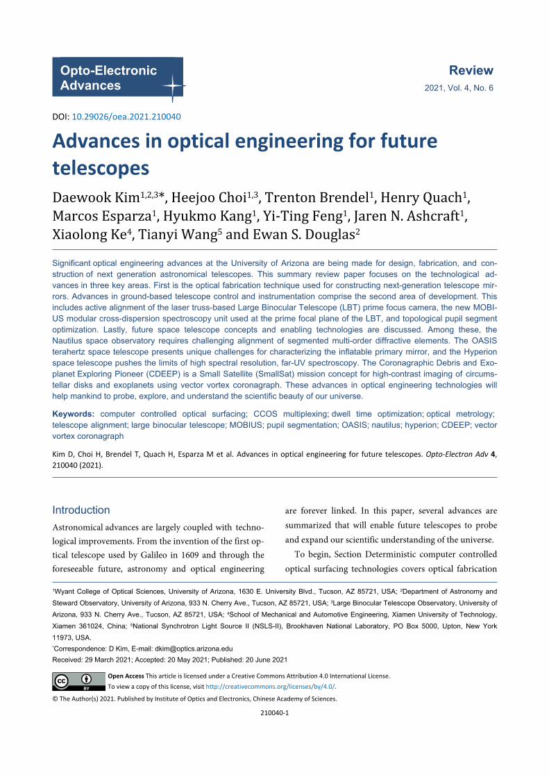
Dual-tool multiplexed polishing model for computercontrolled optical surfacingMany future telescope system designs utilize non-trivialoptical surfaces and components such as freeform lens ormirrors in order to control the aberrations especially forwide field of view systems. Those precision optics manu-facturing efficiency can be significantly improved if mul-tiple fabrication tools are adopted simultaneously in asingle polishing process. For instance, the Large Polish-ing Machine (LPM) in Fig. 1 consists of two tools withdifferent sizes. A 1.2 m diameter stressed lap (labelledTool1) and a 0.3 m diameter non-Newtonian lap (la-belled Tool2) have been used in the LPM to ensure ad-equate removal for the Large Synoptic Survey Telescope(LSST) and GMT. They can be controlled simultan-eously and independently during a single CCOS run.
In order to accelerate the polishing process speed, adual-tool multiplexing polishing model enabling simul-taneous running of the two polishing heads was de-
veloped6. The convolutional material removal model ofan individual tool is defined as
Z (x, y) = R(u, v) ∗ ∗[T (x, y)× V (x, y)× P (x, y)] , (1)
where “**” represents the convolution operator; Z(x,y) isthe removed material distribution, which is equal to theconvolution between the basic Tool Influence Function(TIF) R(u,v) and the product of the dwell time T(x,y), thevelocity V(x,y), and the contact pressures P(x,y). Equa-tion (1) is still valid in the dual-tool multiplexing model.Moreover, since the material removed at a certain dwellpoint in the single-tool model is required to be identicalto that in the dual-tool model, the following boundarycondition BC (BC-1) should be fulfilled,
BC-1 : Zs1(x, y) ≡ Zm
1 (x, y) and Zs2(x, y) ≡ Zm
2 (x, y) ,(2)
Zs1 (x, y) Zs
2 (x, y)
(x, y)Zm1 (x, y) Zm
2 (x, y)(x, y)
where and represents the material re-moved by R1 (the basic TIF of Tool1) and R2 (the basicTIF of Tool2) at in the single-tool model, respect-ively; and represents the material re-moved by R1 and R2 at in the dual-tool model, re-spectively. Since R1 and R2 remain invariant, Eq. (2) canbe further transformed into {
Ts1 × Vs
1 × Ps1 = Tm
1 × Vm1 × Pm
1
Ts2 × Vs
2 × Ps2 = Tm
2 × Vm2 × Pm
2, (3)
Ts1 Vs
1 Ps1
Ts2 Vs
2 Ps2
Tm1 Vm
1 Pm1 Tm
2 Vm2 Pm
2
where , and are the dwell time, the velocity, andthe contact pressure of Tool1 in the single-tool model, re-spectively; and , and are the dwell time, the velo-city, and the contact pressure of Tool2 in the single-toolmodel, respectively. Similarly, , , , , and are the corresponding parameters for Tool1 and Tool2 inthe dual-tool model.
Since LPM works in workpiece rotation mode (seeFig. 1), the simultaneous run of the two tools requires thedwell time for each individual tool to be synchronized.This is achieved by setting one tool (e.g. Tool1) as theprimary tool so that its dwell time and velocities remaininvariant, i.e. {
Ts1(x, y) = Tm
1 (x, y)Vs
1(x, y) = Vm1 (x, y)
. (4)
Tm2
In addition, during simultaneous polishing, Tool1 andTool2 are placed at the opposite locations (i.e. 180°).Therefore, can be calculated with the machine-specif-ic BC (BC-2) as
BC-2 : Tm2 (x, y) ≡ rotate(Tm
1 (x, y), 180◦). (5)
It is worth mentioning that the separation anglebetween Tool1 and Tool2 can be arbitrary. The 180° is
Segment size: Ø8.4 m
Tool2:0.3 m
T2, V2, P2
Tool1:1.2 m
T1, V1, P1
Fig. 1 | Large polishing machine (LPM) with dual tools at theUniversity of Arizona. Figure reproduced with permission from ref.6,
Optical Society of America.
Opto-Electron Adv 4, 210040 (2021) https://doi.org/10.29026/oea.2021.210040
210040-3
Vm2
just the most convenient angle to implement the dual-tool model under LPM’s specific gantry-type configura-tion. Based on Eqs. (4) and (5), is determined as:
Vm2 (x, y) = Vs
2(x, y)Ts
2(x, y)Tm
2 (x, y). (6)
Vm2 (x, y)
Vm2 (x, y)
Vmax2 Tm
2 (x, y) Tm1 (x, y)
Vm1 (x, y)
Vm1 (x, y) Vmax
1
Tm1 (x, y) Tm
2 (x, y) Vm2 (x, y)
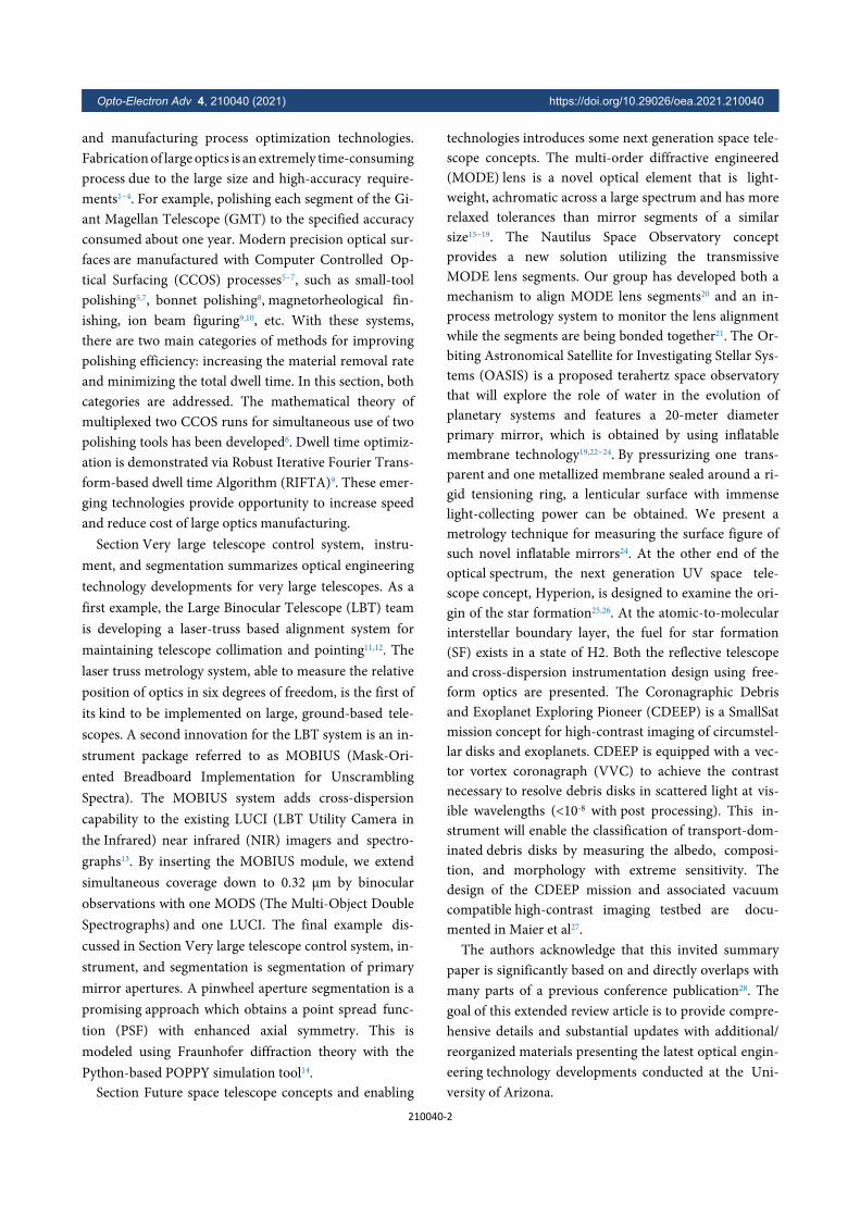
As the contact pressure is often set as constants, all ofthe parameters for the dual-tool model are now syn-chronized. However, obtained from Eq. (6) mayexceed the maximum velocity allowed by the polishingmachine. Therefore, the Velocity Adjustment Algorithm(VAA) shown by the algorithm in Fig. 2 is employed toconstrain the velocities under the valid range. VAA ad-justs the velocities of Tool2 and Tool1 in two loops, re-spectively. In the first loop, is clamped to the
if it is over the range, and , and are updated accordingly. Similarly, in the
second loop, is clamped to the if it is overthe range, and , and are up-dated accordingly.
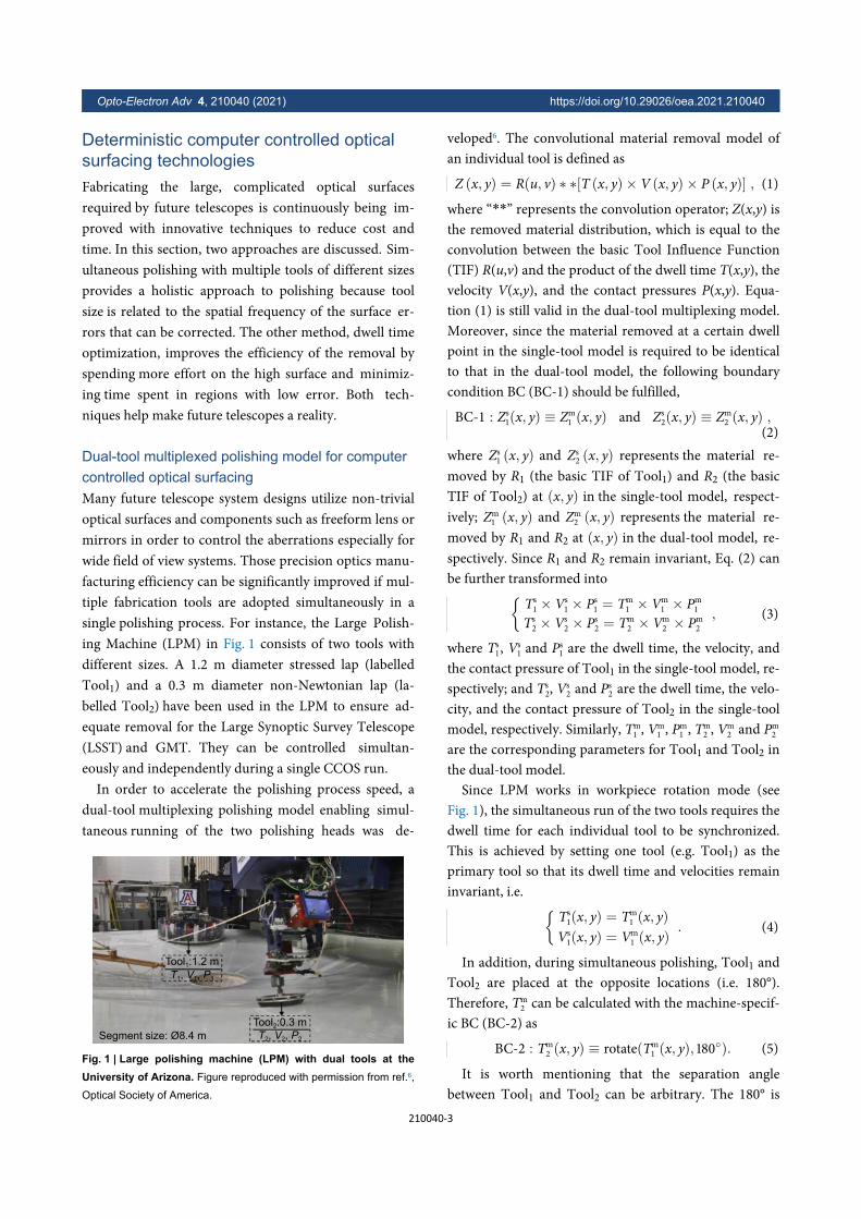
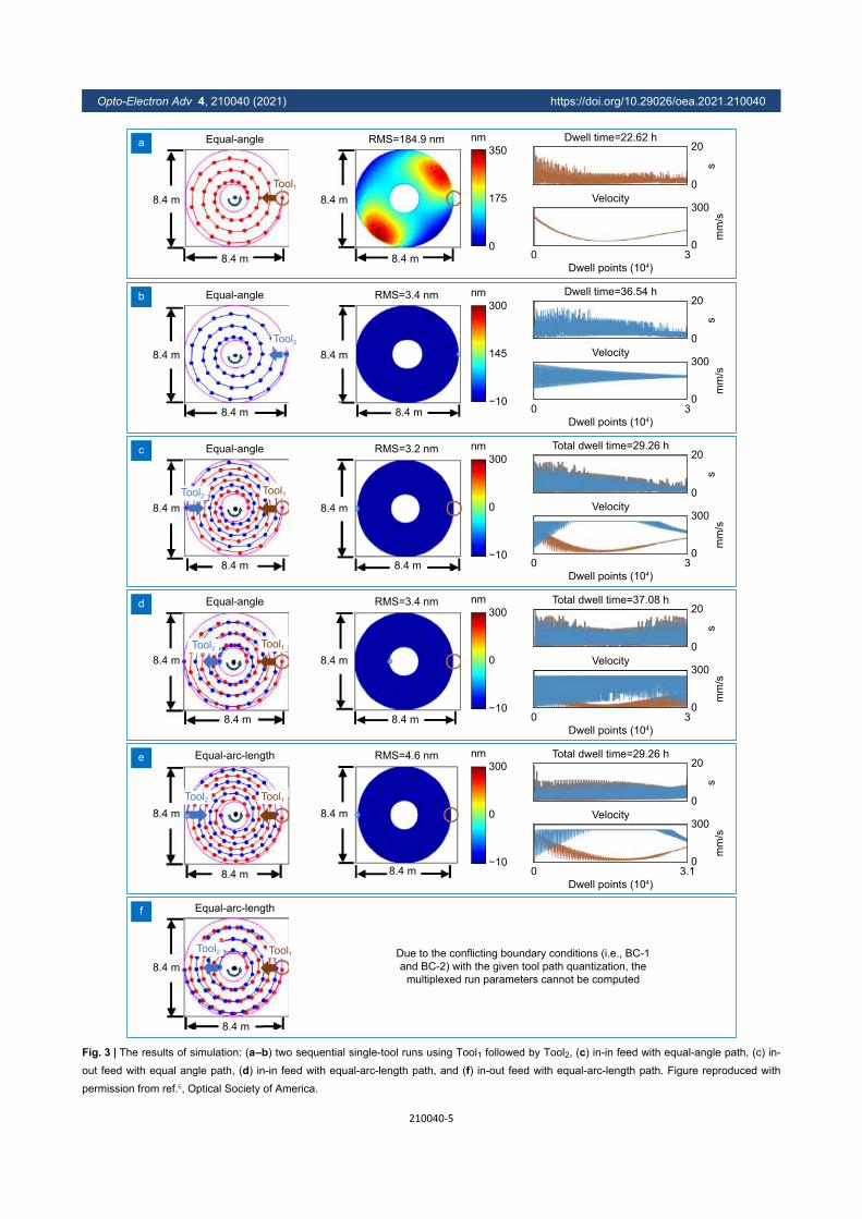
The performances of the single-tool sequential polish-ing and dual-tool simultaneous polishing are studied us-ing a simulated surface error map in shown in Fig. 3,where Figs. 3(a) and 3(b) are the results of two sequen-tial single-tool runs. The figure error is reduced from1.72 μm RMS to 184.9 nm RMS after processed by Tool1(see Fig. 3(a)), which is then further decreased to 3.4 nmRMS by Tool2 shown in Fig. 3(b). The total dwell time ofthe sequential runs is 22.62 + 36.54 = 59.16 h.
In the dual-tool multiplexed model, two tool-feedmodes are tested, namely the in-out mode shown in Figs.3(d) and 3(f) and the in-in mode shown in Figs. 3(c) and3(e). The in-out mode is generally applicable to any dual-tool polishing scenario, because Tool1 and Tool2 move inthe same direction and the tool collision can be avoided.
The in-in mode has the potential problem of tool colli-sion, however, it can also be applied for the GMT on-ax-is segment here, since this problem is automatically re-solved because of the hole at the mirror’s center. Tool1 isselected as the primary tool in the dual-tool polishing, sothat the parameters of Tool2 (i.e. the dwell time and velo-cities) are adjusted and synchronized with those of Tool1.The performances of the in-in and the in-out feed modesare studied with equal-angel and equal-arc-length pathtypes, respectively. With the equal-angel paths, as shownin Figs. 3(c) and 3(d), the in-in feed mode achieves 29.26h, which is shorter than that (37.08 h) of the in-out feedmode. Compared with the single-tool sequential result,the polishing efficiency is improved by 50.54% with thein-in mode.
The two feed modes with the equal-arc-length pathsare further demonstrated in Figs. 3(e) and 3(f). The totaldwell time of the in-in feed mode shown in Fig. 3(e) is29.26 h, which achieves a similar residual error as thosein Figs. 3(c) and 3(d). It is worth mentioning that,however, the in-out feed mode cannot be applied withthe equal-arc-length path as shown in Fig. 3(f), since thetwo tools have different redial positions at any instant sothat the arc lengths cannot be equal.
In a word, the multiplexed dual-tool deterministic pol-ishing model can enable the efficient polishing of largeoptics. Also, the dual-tool multiplexing model can befurther extended to an N-tool model multiplexing Ntools, in which case the polishing efficiency can be fur-ther improved.
Robust iterative Fourier transform-based dwell timealgorithm for CCOSOne of the most essential numerical optimization prob-lems of a CCOS process is to optimize the dwell timewhich controls how much time a tool dwells at a certainposition on the surface of a workpiece. The dwell timeoptimization is guided by the convolutional polishingmodel29,
z (x, y) = b (x, y) ∗ t (x, y) , (7)
∗ b (x, y)z (x, y)
t (x, y) z (x, y)b (x, y) t (x, y)
t (x, y)
where “ ” represents the convolution operation, is the Tool Influence Function (TIF), is the re-moved material, and is the dwell time. and
are known, is thus calculated via deconvo-lution, which is an ill-posed operation that may not res-ult in a reliable and unique solution of . Equation
1: procedure: VAA (Vm1), (V
m2), (T
m1), (T
m2)
2: [m, n] ← [rows (Vm
1), cols (Vm
1)]
4: if Vm2 (x, y) > V2
max then
10: if Vm1 (x, y) > V1
max then
5: Vm2 (x, y) ← V2
max
11: Vm1 (x, y) ← V1
max
6: Tm2 (x, y) = Ts
2 (x, y) × Vs
2 (x, y)/Vm
2 (x, y)
12: Tm1 (x, y) = Ts
1 (x, y) × Vs
1 (x, y)/Vm
1 (x, y)
7: Tm1 ← rotate (Tm
2 , 180°)
13: Tm2 ← rotate (Tm
1 , 180°)
8: Vm1 ← Vs
1 × Ts1/T
m1
14: Vm2 ← Vs
2 × Ts2/T
m2
Adjust Vm2 and Tm
2
Adjust Vm1 and Tm
1
Eq.(5)
Eq.(6)
Eq.(5)
Eq.(6)
3: while y < m and x < n do
9: while y < m and x < n do
Fig. 2 | Flow of velocity adjustment algorithm. Figure reproduced
with permission from ref.6, Optical Society of America.
Opto-Electron Adv 4, 210040 (2021) https://doi.org/10.29026/oea.2021.210040
210040-4
c Equal-angle
8.4 m
8.4 m
Tool1Tool2
RMS=3.2 nm
8.4 m
8.4 m−10
0
300nm
s
20
0
Total dwell time=29.26 h
0 3
mm
/s
300
0
Velocity
Dwell points (104)
d Equal-angle
8.4 m
8.4 m
Tool1Tool2
RMS=3.4 nm
8.4 m
8.4 m−10
0
300nm
s
20
0
Total dwell time=37.08 h
Velocity
0 3m
m/s
300
0
Dwell points (104)
e Equal-arc-length
8.4 m
8.4 m
Tool1Tool2
RMS=4.6 nm
8.4 m
8.4 m−10
0
300nm
s
20
0
Total dwell time=29.26 h
0 3.1
mm
/s
300
0
Velocity
Dwell points (104)
a Equal-angle
8.4 m
8.4 m
Tool1
RMS=184.9 nm
8.4 m
8.4 m0
175
350nm
0 3
mm
/s
300
0
Velocity
Dwell points (104)
s
20
0
Dwell time=22.62 h
f Equal-arc-length
8.4 m
8.4 m
Tool1Tool2 Due to the conflicting boundary conditions (i.e., BC-1
and BC-2) with the given tool path quantization, the
multiplexed run parameters cannot be computed
Equal-angle
8.4 m
8.4 m
Tool2
RMS=3.4 nm
8.4 m
8.4 m−10
145
300nm
s
20
0
Dwell time=36.54 h
0 3
mm
/s
300
0
Velocity
Dwell points (104)
b
Fig. 3 | The results of simulation: (a–b) two sequential single-tool runs using Tool1 followed by Tool2, (c) in-in feed with equal-angle path, (c) in-
out feed with equal angle path, (d) in-in feed with equal-arc-length path, and (f) in-out feed with equal-arc-length path. Figure reproduced with
permission from ref.6, Optical Society of America.
Opto-Electron Adv 4, 210040 (2021) https://doi.org/10.29026/oea.2021.210040
210040-5
t (x, y)
b (x, y) t (x, y)
t (x, y)
(1) implies that, to achieve the desired figure in a ClearAperture (CA), should be optimized on a DwellGrid (DG) which is larger than the outline perimeter ofthe CA with the radius of . A reliable solu-tion should fulfill three requirements. First, it should benon-negative, since CCOS techniques usually do nothave the material adding capability. Second, it shouldminimize the estimated residual in the CA with theshortest total dwell time to guarantee the fabrication effi-ciency. Third, the computation time of should bereasonable.
t (x, y)
t (x, y)
t (x, y) ∗ b (x, y)z (x, y) t (x, y)
t (x, y)
Three categories of dwell time optimization al-gorithms, namely the matrix-based algorithms30−34, theBayesian algorithm35, and the Fourier transform-basedalgorithm36, that partially fulfill these requirements havebeen attempted. The matrix-based algorithms modeledthe deconvolution in an algebraic way, where issolved from an over-determined linear system. Since thematrix is ill-conditioned and rank-deficient, is al-ways unsmooth, unless certain constraints areadded32−34,37. However, the introduction of constraintsmakes the linear system much more complicated whichcannot be efficiently solved when the measurement scaleis large. The Bayesian algorithm35 assumes a Poisson dis-tribution of and a uniform distributionof , from which is solved via the Richard-son-Lucy algorithm38. This algorithm automaticallyguarantees the non-negativity of , however, it con-tains a regularization hyper-parameter, which is hard totune in practice. The Fourier transform-basedalgorithm36 is very computationally efficient since decon-volution is transferred to pointwise division in fre-quency domain by the Fast Fourier Transform (FFT) al-gorithm as
t (x, y) = F−1[Zd (u, v)B (u, v)
], (8)
F−1
Zd (u, v)zd (x, y) B (u, v)b (x, y)
where “ ” represents the inverse Fourier transform, is the Fourier transform of the desired removal
on the dwell grid, i.e. , and is the Fouriertransform of the TIF . However, the close-to-zerofrequencies during the division may amplify the noiseand a thresholded inverse filtering step is introduced as
t (x, y) = F−1[Zd (u, v)B (u, v; γ)
], (9)
where γ is the threshold value and
B (u, v; γ) ={B (u, v) , ∥B (u, v)∥ > γ
γ, otherwise. (10)
This threshold value again, becomes a hyper-paramet-er that is usually chosen by trial-and-error.
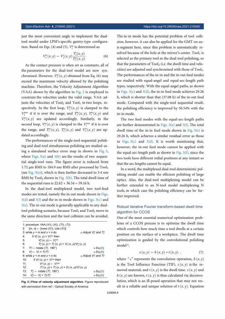
Based on the Fourier transform-based algorithm, weproposed a Robust Iterative Fourier Transform-baseddwell time Algorithm (RIFTA)9 that fulfills all the threecharacteristics of dwell time mentioned above whilemaintains FFT’s high computational efficiency. First, theNelder-Mead algorithm39 was employed to directlysearch the optimal threshold γ for the thresholded in-verse filtering. Second, a two-level iterative scheme wasproposed to guarantee the non-negativity of the dwelltime with the minimal increase in the total dwell time.Third, bicubic resampling was introduced to flexibly ad-apt the calculated dwell time to any machining intervalsin a real CCOS process. The algorithm flow of RIFTA isgiven in Algorithm 1, which is briefly explained in thefollowings. Details of RIFTA can be found in ref.9.
zrzd
z (x, y)
Finding the optimal γ. We define a residual map tobe the difference between the desired removal and theremoved material as
zr = zd − z . (11)t (x, y)
zr RMS [zr]
The effectiveness of can ben quantitatively eval-uated by interrogating the Root Mean Square (RMS) of
as . The optimal γ can be found from an un-constrained optimization problem as
γopt = argminγ
RMS [zr (x, y)] . (12)
Substituting Eqs. (7), (9) and (11) to Eq. (12), the op-timization objective can be reformulated as
γopt =
argminγ
RMS{zd (x, y)− b (x, y) ∗ F−1
[ZDG (u, v)B (u, v; γ)
]}.
(13)
γopt γiniRMS [zd] RMS [zr]
γ = 1
It can be observed that the optimization space in Eq.(13) is not smooth due to the thresholding and croppingoperations. Its gradients thus cannot be calculated so thatany derivative-based optimization algorithms can hardlybe applied. In RIFTA, as shown in Line 8 in the RIFTAalgorithm in Fig. 4, the Nelder-Mead algorithm is ap-plied to directly search . The initial guess is ob-tained as the ratio between and when
.zd
tTwo-level iterative scheme. If the smallest entry of
is outside the CA, to ensure the non-negativity of , aconstant piston should be added to offset the smallestentry in the DG. This operation, however, will inadvert-ently increase the total dwell time. Therefore, in RIFTA,
Opto-Electron Adv 4, 210040 (2021) https://doi.org/10.29026/oea.2021.210040
210040-6
zr_ca zdmin (zr_ca) min (·)
·t
zd
as shown by Lines 6 – 16 in Algorithm (Fig. 4), the inneriterations only depend on the residuals in the CA, i.e
, to adjust the pistons in the DG. In each iteration, is only offset by a piston of , where rep-resents the minimum entry in “ ”. The negative entries inthe calculated , as shown in Line 9, are set as zeros inLine 10. In this way, is always guaranteed to be adjus-ted by the smallest pistons during the iterative updates.As shown in Line 15, these inner iterations are per-formed until the Standard Deviation (STD) of the differ-ence between the current and the previous residuals inthe CA is less than the threshold std_t or the maximumnumber of iteration max_it is reached. The outer itera-tions are then added to tune the size of the DG, since we
zr_ca
s = ⌊rb/2⌋
found that a much smaller DG is sufficient to obtain thedesired while the total dwell time is significantly re-duced. As shown in Algorithm 1, starting from
, the outer iterations keep searching for thesmallest s that fulfills the same stopping criteria as the in-ner iterations.
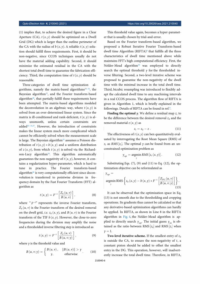
Bicubic resampling. To enable the flexibility of hav-ing different sampling intervals between metrology andfabrication hardware, we use bicubic resampling todownsample t to any required machining intervals that aCCOS process requires. As shown in Fig. 5, the al-gorithmic accuracy is not affected by this resamplingscheme.
The performance of RIFTA is evaluated on real meas-urement data shown in Fig. 5(a), where a rectangular flatmirror is measured with 0.12 mm sampling interval us-ing the sub-aperture stitching interferometry plat-form40,41. The size of the CA is set as 200 mm × 5 mm.The initial figure error in the CA is 167.02 nm Peak-to-Valley (PV) and 38.39 nm RMS. We use a Gaussian TIFwith the peak removal rate of 1 nm/s and a radius of5 mm so that the initial DG size is 210 mm × 15 mm.
γini = 1.6709× 10⁶
γopt = 1.6650× 10⁶
Figures 5(b−f) shows the different dwell time calcula-tion results. The corresponding estimated residuals inthe CA are given in Figs. 5(g−k). Without using RIFTA,as shown in Figs. 5(b) and 5(g), the total dwell time is3411.32 mins while the residual in the CA remains at8.44 nm RMS using , which indicatesthat the calculated dwell time is far from the optimalsolution. After γ is optimized as , the
Algorithm 1. RIFTA dwell time algorithm
2: rb ← radius of b, s ← [rb/2]
4: it ← 0, zr_ca ← Inf5: do
15: while STD [zr_ca − ] ≥ std_t and it < max_it
6: zr_ca ← zr_ca
7: zd ← zd − min(zr_ca)
8: γopt = Opt_ γ(γini
, zd, b)
10: t(t < 0) = 011: z = b × t
12: zr = zd − z13: zr_ca = zr [size(CA)]
18: t = Bicubic_Resampling(t)19: return t
14: it ← it + 1
16: s ← s + 1
pre
zr_capre
17: while STD [zr_ca − ] ≥ std_t and s < rbzr_cas=r
b
3: do
9: t = F−1 [Zd/B]−
Outer iterations
Inneriterations
Piston adjustmentEq.(13)
Eq.(9 & 10)
Eq.(7)
Eq.(11)
Residual in CA
Resample t
1: procedure RIFTA (zd, b, CA, std_t, max_it)
Fig. 4 | Flow of RIFTA dwell time algorithm.
15 mm
15 mm
15 mm
12.6 mm
12.6 mm
35.6 mm
5 mm
PV=1511.36 nm, RMS=237.26 nm
Total dwell time=3411.32 mins
Total dwell time=3411.76 mins
Total dwell time=584.28 mins
Total dwell time=479.08 mins
Total dwell time=488.77 mins
306.11
−1205.25
nm
nm
nm
nm
167.02
−16.68
−1.781.93
13.80
0
nm
nm
nm
s
s
s
s
s
−2.07
−2.08
1.93
1.97
−2.091.97
216.1 mm
Initial figure error, PV=167.02 nm, RMS=38.39 nm
200 mm
PV=30.66 nm, RMS=8.44 nm
PV=3.71 nm, RMS=0.47 nm
PV=4.01 nm, RMS=0.46 nm
PV=4.05 nm, RMS=0.46 nm
PV=4.07 nm, RMS=0.47 nm
210 mm
210 mm
210 mm
207.4 mm
207.4 mm
Clear aperture
Add γ optimization
Add inner iterations
Add outer iterations
Resample to 1 mm
1.06
0
1.04
0
0.28
0
0.28
0
18.88
0
b
c
d
e
f
a
g
h
i
j
k
Without γ optimization
Fig. 5 | (a) Initial surface error map from real measurement, (b−f) dwell time calculation results, and (g−k) estimated residuals in the CA without
using RIFTA (b, g), adding γ optimization (c, h), adding inner iterations (d, i), adding outer iterations (e, j), and resampling to 1 mm (f, k).
Opto-Electron Adv 4, 210040 (2021) https://doi.org/10.29026/oea.2021.210040
210040-7
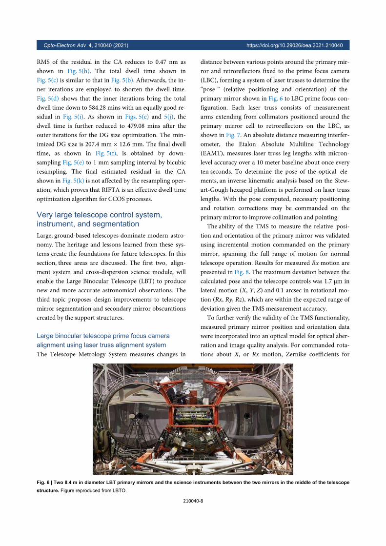
RMS of the residual in the CA reduces to 0.47 nm asshown in Fig. 5(h). The total dwell time shown inFig. 5(c) is similar to that in Fig. 5(b). Afterwards, the in-ner iterations are employed to shorten the dwell time.Fig. 5(d) shows that the inner iterations bring the totaldwell time down to 584.28 mins with an equally good re-sidual in Fig. 5(i). As shown in Figs. 5(e) and 5(j), thedwell time is further reduced to 479.08 mins after theouter iterations for the DG size optimization. The min-imized DG size is 207.4 mm × 12.6 mm. The final dwelltime, as shown in Fig. 5(f), is obtained by down-sampling Fig. 5(e) to 1 mm sampling interval by bicubicresampling. The final estimated residual in the CAshown in Fig. 5(k) is not affected by the resampling oper-ation, which proves that RIFTA is an effective dwell timeoptimization algorithm for CCOS processes.
Very large telescope control system,instrument, and segmentationLarge, ground-based telescopes dominate modern astro-nomy. The heritage and lessons learned from these sys-tems create the foundations for future telescopes. In thissection, three areas are discussed. The first two, align-ment system and cross-dispersion science module, willenable the Large Binocular Telescope (LBT) to producenew and more accurate astronomical observations. Thethird topic proposes design improvements to telescopemirror segmentation and secondary mirror obscurationscreated by the support structures.
Large binocular telescope prime focus cameraalignment using laser truss alignment systemThe Telescope Metrology System measures changes in
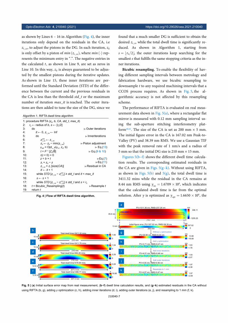
distance between various points around the primary mir-ror and retroreflectors fixed to the prime focus camera(LBC), forming a system of laser trusses to determine the“pose ” (relative positioning and orientation) of theprimary mirror shown in Fig. 6 to LBC prime focus con-figuration. Each laser truss consists of measurementarms extending from collimators positioned around theprimary mirror cell to retroreflectors on the LBC, asshown in Fig. 7. An absolute distance measuring interfer-ometer, the Etalon Absolute Multiline Technology(EAMT), measures laser truss leg lengths with micron-level accuracy over a 10 meter baseline about once everyten seconds. To determine the pose of the optical ele-ments, an inverse kinematic analysis based on the Stew-art-Gough hexapod platform is performed on laser trusslengths. With the pose computed, necessary positioningand rotation corrections may be commanded on theprimary mirror to improve collimation and pointing.
The ability of the TMS to measure the relative posi-tion and orientation of the primary mirror was validatedusing incremental motion commanded on the primarymirror, spanning the full range of motion for normaltelescope operation. Results for measured Rx motion arepresented in Fig. 8. The maximum deviation between thecalculated pose and the telescope controls was 1.7 μm inlateral motion (X, Y, Z) and 0.1 arcsec in rotational mo-tion (Rx, Ry, Rz), which are within the expected range ofdeviation given the TMS measurement accuracy.
To further verify the validity of the TMS functionality,measured primary mirror position and orientation datawere incorporated into an optical model for optical aber-ration and image quality analysis. For commanded rota-tions about X, or Rx motion, Zernike coefficients for
Fig. 6 | Two 8.4 m in diameter LBT primary mirrors and the science instruments between the two mirrors in the middle of the telescopestructure. Figure reproduced from LBTO.
Opto-Electron Adv 4, 210040 (2021) https://doi.org/10.29026/oea.2021.210040
210040-8
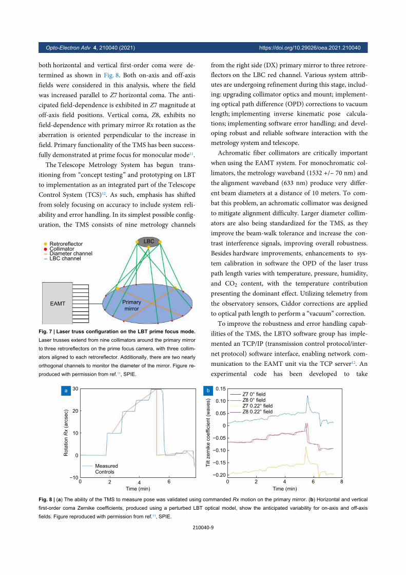
both horizontal and vertical first-order coma were de-termined as shown in Fig. 8. Both on-axis and off-axisfields were considered in this analysis, where the fieldwas increased parallel to Z7 horizontal coma. The anti-cipated field-dependence is exhibited in Z7 magnitude atoff-axis field positions. Vertical coma, Z8, exhibits nofield-dependence with primary mirror Rx rotation as theaberration is oriented perpendicular to the increase infield. Primary functionality of the TMS has been success-fully demonstrated at prime focus for monocular mode11.
The Telescope Metrology System has begun trans-itioning from “concept testing” and prototyping on LBTto implementation as an integrated part of the TelescopeControl System (TCS)12. As such, emphasis has shiftedfrom solely focusing on accuracy to include system reli-ability and error handling. In its simplest possible config-uration, the TMS consists of nine metrology channels
from the right side (DX) primary mirror to three retrore-flectors on the LBC red channel. Various system attrib-utes are undergoing refinement during this stage, includ-ing: upgrading collimator optics and mount; implement-ing optical path difference (OPD) corrections to vacuumlength; implementing inverse kinematic pose calcula-tions; implementing software error handling; and devel-oping robust and reliable software interaction with themetrology system and telescope.
Achromatic fiber collimators are critically importantwhen using the EAMT system. For monochromatic col-limators, the metrology waveband (1532 +/– 70 nm) andthe alignment waveband (633 nm) produce very differ-ent beam diameters at a distance of 10 meters. To com-bat this problem, an achromatic collimator was designedto mitigate alignment difficulty. Larger diameter collim-ators are also being standardized for the TMS, as theyimprove the beam-walk tolerance and increase the con-trast interference signals, improving overall robustness.Besides hardware improvements, enhancements to sys-tem calibration in software the OPD of the laser trusspath length varies with temperature, pressure, humidity,and CO2 content, with the temperature contributionpresenting the dominant effect. Utilizing telemetry fromthe observatory sensors, Ciddor corrections are appliedto optical path length to perform a “vacuum” correction.
To improve the robustness and error handling capab-ilities of the TMS, the LBTO software group has imple-mented an TCP/IP (transmission control protocol/inter-net protocol) software interface, enabling network com-munication to the EAMT unit via the TCP server12. Anexperimental code has been developed to take
EAMT
RetroreflectorCollimatorDiameter channelLBC channel
LBC
Primary
mirror
Fig. 7 | Laser truss configuration on the LBT prime focus mode.Laser trusses extend from nine collimators around the primary mirror
to three retroreflectors on the prime focus camera, with three collim-
ators aligned to each retroreflector. Additionally, there are two nearly
orthogonal channels to monitor the diameter of the mirror. Figure re-
produced with permission from ref.11, SPIE.
MeasuredControls
30
20
10
0
−100 2 4
Time (min)
6 0 2 4
Time (min)
6 8
0.15
0.10
0.05
0
−0.05
−0.10
−0.15
−0.20
Tilt
zern
ike c
oeffic
ient (w
ave
s)
a b
Rot
atio
n Rx
(arc
sec)
Z7 0° fieldZ8 0° fieldZ7 0.22° fieldZ8 0.22° field
Fig. 8 | (a) The ability of the TMS to measure pose was validated using commanded Rx motion on the primary mirror. (b) Horizontal and vertical
first-order coma Zernike coefficients, produced using a perturbed LBT optical model, show the anticipated variability for on-axis and off-axis
fields. Figure reproduced with permission from ref.11, SPIE.
Opto-Electron Adv 4, 210040 (2021) https://doi.org/10.29026/oea.2021.210040
210040-9
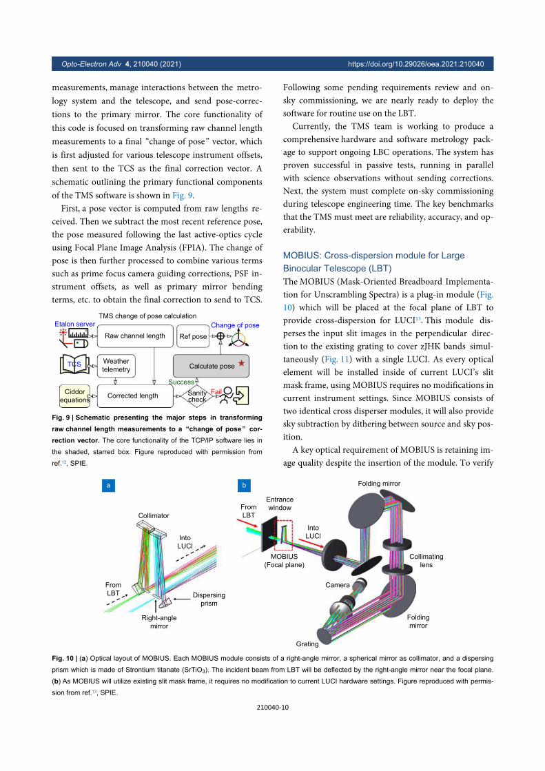
measurements, manage interactions between the metro-logy system and the telescope, and send pose-correc-tions to the primary mirror. The core functionality ofthis code is focused on transforming raw channel lengthmeasurements to a final “change of pose” vector, whichis first adjusted for various telescope instrument offsets,then sent to the TCS as the final correction vector. Aschematic outlining the primary functional componentsof the TMS software is shown in Fig. 9.
First, a pose vector is computed from raw lengths re-ceived. Then we subtract the most recent reference pose,the pose measured following the last active-optics cycleusing Focal Plane Image Analysis (FPIA). The change ofpose is then further processed to combine various termssuch as prime focus camera guiding corrections, PSF in-strument offsets, as well as primary mirror bendingterms, etc. to obtain the final correction to send to TCS.
Following some pending requirements review and on-sky commissioning, we are nearly ready to deploy thesoftware for routine use on the LBT.
Currently, the TMS team is working to produce acomprehensive hardware and software metrology pack-age to support ongoing LBC operations. The system hasproven successful in passive tests, running in parallelwith science observations without sending corrections.Next, the system must complete on-sky commissioningduring telescope engineering time. The key benchmarksthat the TMS must meet are reliability, accuracy, and op-erability.
MOBIUS: Cross-dispersion module for LargeBinocular Telescope (LBT)The MOBIUS (Mask-Oriented Breadboard Implementa-tion for Unscrambling Spectra) is a plug-in module (Fig.10) which will be placed at the focal plane of LBT toprovide cross-dispersion for LUCI13. This module dis-perses the input slit images in the perpendicular direc-tion to the existing grating to cover zJHK bands simul-taneously (Fig. 11) with a single LUCI. As every opticalelement will be installed inside of current LUCI’s slitmask frame, using MOBIUS requires no modifications incurrent instrument settings. Since MOBIUS consists oftwo identical cross disperser modules, it will also providesky subtraction by dithering between source and sky pos-ition.
A key optical requirement of MOBIUS is retaining im-age quality despite the insertion of the module. To verify
TMS change of pose calculation
Etalon server
TCS
Ciddor
equations
Raw channel length Ref pose
Change of pose
Weather
telemetry
Corrected length
Calculate pose
Sanitycheck
Success
Fail
Fig. 9 | Schematic presenting the major steps in transformingraw channel length measurements to a “change of pose” cor-rection vector. The core functionality of the TCP/IP software lies in
the shaded, starred box. Figure reproduced with permission from
ref.12, SPIE.
From
LBT
Collimator
Into
LUCl
Dispersing
prism
Right-angle
mirror
From
LBT
Entrance
window
MOBIUS
(Focal plane)
Into
LUCl
Folding mirror
Collimating
lens
Folding
mirror
Camera
Grating
a b
Fig. 10 | (a) Optical layout of MOBIUS. Each MOBIUS module consists of a right-angle mirror, a spherical mirror as collimator, and a dispersing
prism which is made of Strontium titanate (SrTiO3). The incident beam from LBT will be deflected by the right-angle mirror near the focal plane.
(b) As MOBIUS will utilize existing slit mask frame, it requires no modification to current LUCI hardware settings. Figure reproduced with permis-
sion from ref.13, SPIE.
Opto-Electron Adv 4, 210040 (2021) https://doi.org/10.29026/oea.2021.210040
210040-10
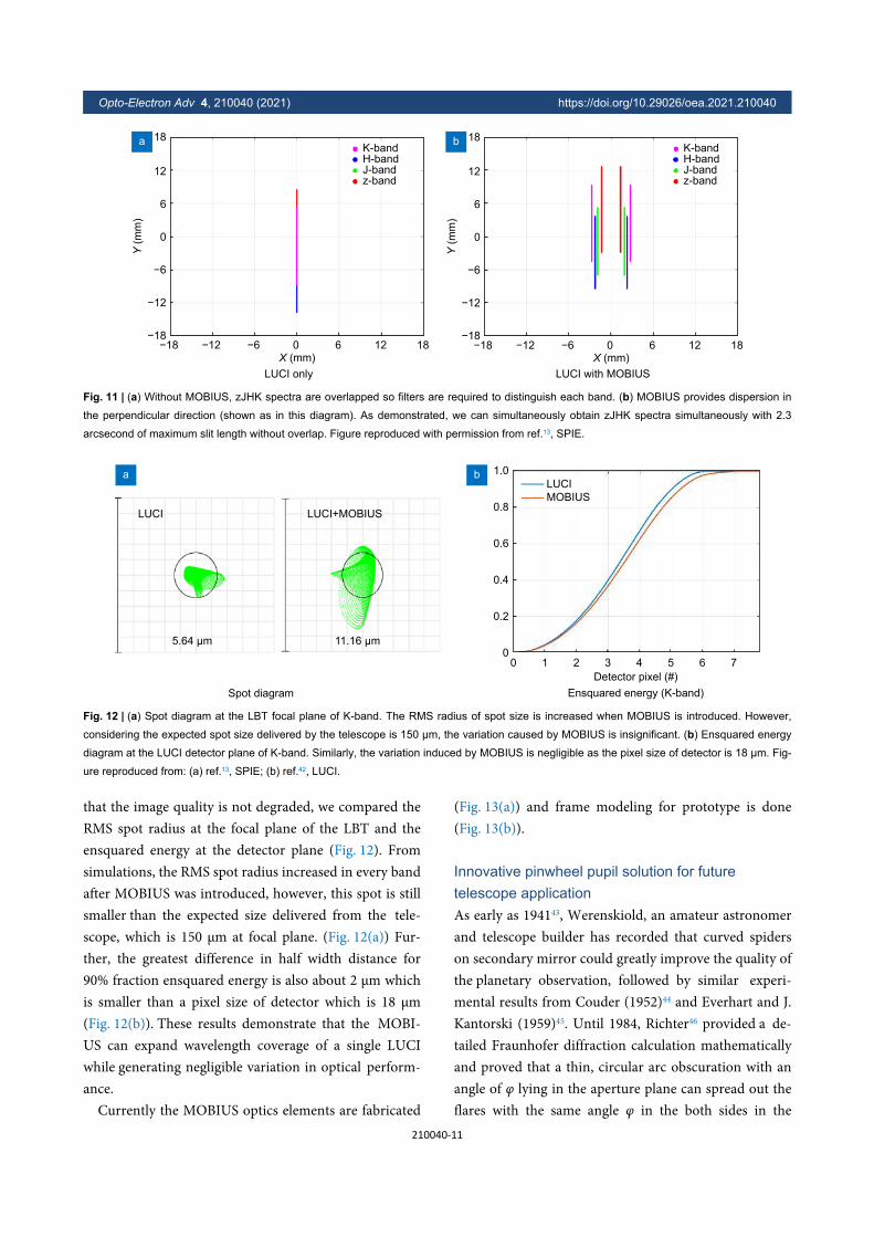
that the image quality is not degraded, we compared theRMS spot radius at the focal plane of the LBT and theensquared energy at the detector plane (Fig. 12). Fromsimulations, the RMS spot radius increased in every bandafter MOBIUS was introduced, however, this spot is stillsmaller than the expected size delivered from the tele-scope, which is 150 μm at focal plane. (Fig. 12(a)) Fur-ther, the greatest difference in half width distance for90% fraction ensquared energy is also about 2 μm whichis smaller than a pixel size of detector which is 18 μm(Fig. 12(b)). These results demonstrate that the MOBI-US can expand wavelength coverage of a single LUCIwhile generating negligible variation in optical perform-ance.
Currently the MOBIUS optics elements are fabricated
(Fig. 13(a)) and frame modeling for prototype is done(Fig. 13(b)).
Innovative pinwheel pupil solution for futuretelescope applicationAs early as 194143, Werenskiold, an amateur astronomerand telescope builder has recorded that curved spiderson secondary mirror could greatly improve the quality ofthe planetary observation, followed by similar experi-mental results from Couder (1952)44 and Everhart and J.Kantorski (1959)45. Until 1984, Richter46 provided a de-tailed Fraunhofer diffraction calculation mathematicallyand proved that a thin, circular arc obscuration with anangle of φ lying in the aperture plane can spread out theflares with the same angle φ in the both sides in the
18
12
6
0
−6
−12
−18−18 −12 −6 0
X (mm)6 12 18
Y (
mm
)18
12
6
0
−6
−12
−18−18 −12 −6 0
X (mm)6 12 18
Y (
mm
)
K-bandH-bandJ-bandz-band
LUCI only LUCI with MOBIUS
K-bandH-bandJ-bandz-band
a b
Fig. 11 | (a) Without MOBIUS, zJHK spectra are overlapped so filters are required to distinguish each band. (b) MOBIUS provides dispersion in
the perpendicular direction (shown as in this diagram). As demonstrated, we can simultaneously obtain zJHK spectra simultaneously with 2.3
arcsecond of maximum slit length without overlap. Figure reproduced with permission from ref.13, SPIE.
LUCI
5.64 μm
LUCI+MOBIUS
11.16 μm
Spot diagram
a
Ensquared energy (K-band)
LUCI
MOBIUS
1.0
0.8
0.6
0.4
0.2
00 1 2 3 4
Detector pixel (#)
5 6 7
b
Fig. 12 | (a) Spot diagram at the LBT focal plane of K-band. The RMS radius of spot size is increased when MOBIUS is introduced. However,
considering the expected spot size delivered by the telescope is 150 μm, the variation caused by MOBIUS is insignificant. (b) Ensquared energy
diagram at the LUCI detector plane of K-band. Similarly, the variation induced by MOBIUS is negligible as the pixel size of detector is 18 μm. Fig-
ure reproduced from: (a) ref.13, SPIE; (b) ref.42, LUCI.
Opto-Electron Adv 4, 210040 (2021) https://doi.org/10.29026/oea.2021.210040
210040-11
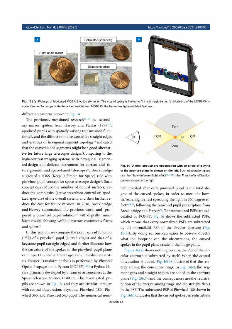
diffraction patterns, shown in Fig. 14.The previously-mentioned research43−45, the second-
ary mirror spiders from Harvey and Ftaclas (1995)47,apodized pupils with spatially varying transmission func-tions48, and the diffraction noise caused by straight edgesand gratings of hexagonal segment topology49 indicatedthat the curved-sided segments might be a good alternat-ive for future large telescopes design. Comparing to thehigh-contrast imaging systems with hexagonal segmen-ted design and delicate instrument for current and fu-ture ground- and space-based telescopes50, Breckinridgesuggested a KISS (Keep It Simple for Space) rule withpinwheel pupil concept for space telescope design51. Suchconcept can reduce the number of optical surfaces, re-duce the complexity (active wavefront control or apod-ized aperture) of the overall system, and then further re-duce the cost for future mission. In 2018, Breckinridgeand Harvey summarized the previous work, and pro-posed a pinwheel pupil solution49 with digitally simu-lated results showing without narrow continuous flaresand spikes52.
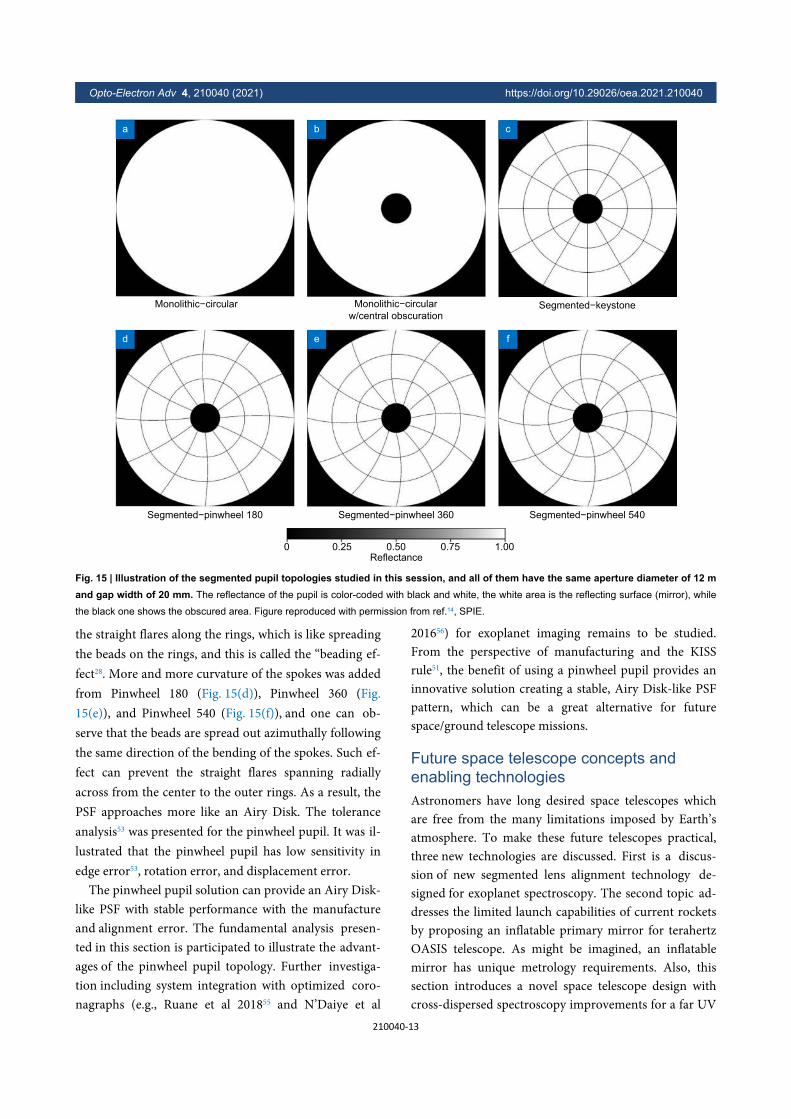
In this section, we compare the point spread function(PSF) of a pinwheel pupil (curved edges) and that of akeystone pupil (straight edges) and further illustrate howthe curvature of the spokes in the pinwheel pupil planecan impact the PSF in the image plane. The discrete mat-rix Fourier Transform analysis is performed by PhysicalOptics Propagation in Python (POPPY)53,54, a Python lib-rary primarily developed by a team of astronomers at theSpace Telescope Science Institute. The investigated pu-pils are shown in Fig. 15, and they are circular, circularwith central obscuration, keystone, Pinwheel 180, Pin-wheel 360, and Pinwheel 540 pupil. The numerical num-
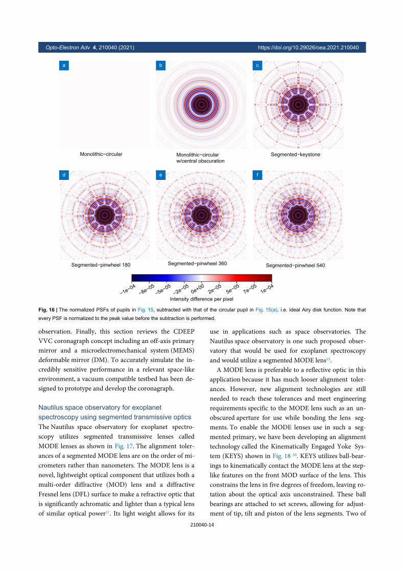
ber indicated after each pinwheel pupil is the total de-gree of the curved spokes, in order to meet the bow-tie/searchlight effect spreading the light in 360 degree ef-fect46,49,53, following the pinwheel pupil prescription fromBreckinridge and Harvey52. The normalized PSFs are cal-culated by POPPY. Fig. 16 shows the subtracted PSFs,which means that every normalized PSFs are subtractedby the normalized PSF of the circular aperture (Fig.15(a)). By doing so, one can easier to observe directlywhat the footprint can the obscurations, the curvedspokes in the pupil plane create in the image plane.
Figure 16(a) shows nothing because the PSF of the cir-cular aperture is subtracted by itself. When the centralobscuration is added, Fig. 16(b) illustrated that the en-ergy among the concentric rings. In Fig. 16(c), the seg-ment gaps and straight spokes are added to the apertureplane (Fig. 15(c)), and the consequences are the redistri-bution of the energy among rings and the straight flaresin the PSF. The subtracted PSF of Pinwheel 180 shown inFig. 16(d) indicates that the curved spokes can redistribute
Right-angle mirror
Collimator (spherical)
Dispersing prism
a b
Fig. 13 | (a) Pictures of fabricated MOBIUS optics elements. The size of optics is limited to fit in slit mask frame. (b) Modeling of the MOBIUS-in-
stalled frame. To compensate the added weight from MOBIUS, the frame has light-weighted features.
Light Light
Dark
Dark
φ φ
Fig. 14 | A thin, circular arc obscuration with an angle of φ lyingin the aperture plane is shown on the left. Such obscuration gives
rise the “bow-tie/searchlight effect46,49,53in the Fraunhofer diffraction
pattern shown on the right.
Opto-Electron Adv 4, 210040 (2021) https://doi.org/10.29026/oea.2021.210040
210040-12
the straight flares along the rings, which is like spreadingthe beads on the rings, and this is called the “beading ef-fect28. More and more curvature of the spokes was addedfrom Pinwheel 180 (Fig. 15(d)), Pinwheel 360 (Fig.15(e)), and Pinwheel 540 (Fig. 15(f)), and one can ob-serve that the beads are spread out azimuthally followingthe same direction of the bending of the spokes. Such ef-fect can prevent the straight flares spanning radiallyacross from the center to the outer rings. As a result, thePSF approaches more like an Airy Disk. The toleranceanalysis53 was presented for the pinwheel pupil. It was il-lustrated that the pinwheel pupil has low sensitivity inedge error53, rotation error, and displacement error.
The pinwheel pupil solution can provide an Airy Disk-like PSF with stable performance with the manufactureand alignment error. The fundamental analysis presen-ted in this section is participated to illustrate the advant-ages of the pinwheel pupil topology. Further investiga-tion including system integration with optimized coro-nagraphs (e.g., Ruane et al 201855 and N’Daiye et al
201656) for exoplanet imaging remains to be studied.From the perspective of manufacturing and the KISSrule51, the benefit of using a pinwheel pupil provides aninnovative solution creating a stable, Airy Disk-like PSFpattern, which can be a great alternative for futurespace/ground telescope missions.
Future space telescope concepts andenabling technologiesAstronomers have long desired space telescopes whichare free from the many limitations imposed by Earth’satmosphere. To make these future telescopes practical,three new technologies are discussed. First is a discus-sion of new segmented lens alignment technology de-signed for exoplanet spectroscopy. The second topic ad-dresses the limited launch capabilities of current rocketsby proposing an inflatable primary mirror for terahertzOASIS telescope. As might be imagined, an inflatablemirror has unique metrology requirements. Also, thissection introduces a novel space telescope design withcross-dispersed spectroscopy improvements for a far UV
Monolithic−circular Monolithic−circularw/central obscuration
Segmented−keystone
Segmented−pinwheel 180 Segmented−pinwheel 360 Segmented−pinwheel 540
0 0.25 0.50Reflectance
0.75 1.00
a b c
d e f
Fig. 15 | Illustration of the segmented pupil topologies studied in this session, and all of them have the same aperture diameter of 12 mand gap width of 20 mm. The reflectance of the pupil is color-coded with black and white, the white area is the reflecting surface (mirror), while
the black one shows the obscured area. Figure reproduced with permission from ref.14, SPIE.
Opto-Electron Adv 4, 210040 (2021) https://doi.org/10.29026/oea.2021.210040
210040-13
observation. Finally, this section reviews the CDEEPVVC coronagraph concept including an off-axis primarymirror and a microelectromechanical system (MEMS)deformable mirror (DM). To accurately simulate the in-credibly sensitive performance in a relevant space-likeenvironment, a vacuum compatible testbed has been de-signed to prototype and develop the coronagraph.
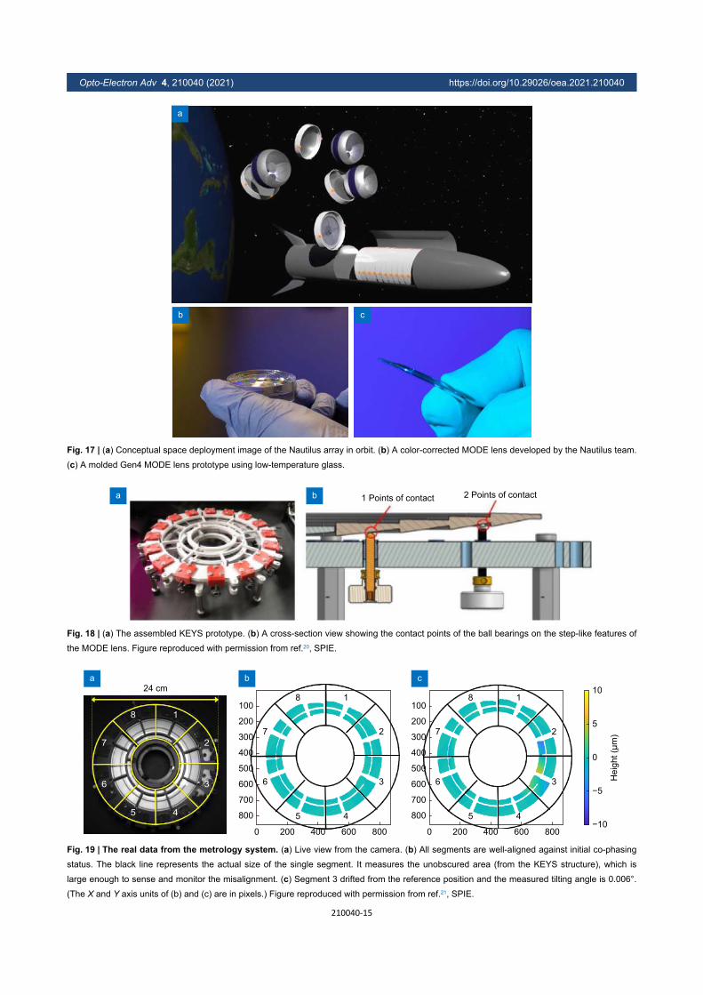
Nautilus space observatory for exoplanetspectroscopy using segmented transmissive opticsThe Nautilus space observatory for exoplanet spectro-scopy utilizes segmented transmissive lenses calledMODE lenses as shown in Fig. 17. The alignment toler-ances of a segmented MODE lens are on the order of mi-crometers rather than nanometers. The MODE lens is anovel, lightweight optical component that utilizes both amulti-order diffractive (MOD) lens and a diffractiveFresnel lens (DFL) surface to make a refractive optic thatis significantly achromatic and lighter than a typical lensof similar optical power57. Its light weight allows for its
use in applications such as space observatories. TheNautilus space observatory is one such proposed obser-vatory that would be used for exoplanet spectroscopyand would utilize a segmented MODE lens15.
A MODE lens is preferable to a reflective optic in thisapplication because it has much looser alignment toler-ances. However, new alignment technologies are stillneeded to reach these tolerances and meet engineeringrequirements specific to the MODE lens such as an un-obscured aperture for use while bonding the lens seg-ments. To enable the MODE lenses use in such a seg-mented primary, we have been developing an alignmenttechnology called the Kinematically Engaged Yoke Sys-tem (KEYS) shown in Fig. 18 20. KEYS utilizes ball-bear-ings to kinematically contact the MODE lens at the step-like features on the front MOD surface of the lens. Thisconstrains the lens in five degrees of freedom, leaving ro-tation about the optical axis unconstrained. These ballbearings are attached to set screws, allowing for adjust-ment of tip, tilt and piston of the lens segments. Two of
Monolithic−circular Monolithic−circularw/central obscuration
Segmented−keystone
Segmented−pinwheel 180 Segmented−pinwheel 360 Segmented−pinwheel 540
−1e−04−8e−05
−5e−05−2e−05
0e+002e−05
5e−057e−05
1e−04
Intensity difference per pixel
a b c
d e f
Fig. 16 | The normalized PSFs of pupils in Fig. 15, subtracted with that of the circular pupil in Fig. 15(a), i.e. ideal Airy disk function. Note that
every PSF is normalized to the peak value before the subtraction is performed.
Opto-Electron Adv 4, 210040 (2021) https://doi.org/10.29026/oea.2021.210040
210040-14
a
b c
Fig. 17 | (a) Conceptual space deployment image of the Nautilus array in orbit. (b) A color-corrected MODE lens developed by the Nautilus team.
(c) A molded Gen4 MODE lens prototype using low-temperature glass.
1 Points of contact 2 Points of contacta b
Fig. 18 | (a) The assembled KEYS prototype. (b) A cross-section view showing the contact points of the ball bearings on the step-like features of
the MODE lens. Figure reproduced with permission from ref.20, SPIE.
24 cm
5 4
8 1
36
27
10
5
0
Hei
ght (
μm)
−5
−10800
2000
5 4
8 1
36
27
400 600 800
700
600
500
400
300
200
100
800
2000
5 4
8 1
36
27
400 600 800
700
600
500
400
300
200
100
a b c
Fig. 19 | The real data from the metrology system. (a) Live view from the camera. (b) All segments are well-aligned against initial co-phasing
status. The black line represents the actual size of the single segment. It measures the unobscured area (from the KEYS structure), which is
large enough to sense and monitor the misalignment. (c) Segment 3 drifted from the reference position and the measured tilting angle is 0.006°.
(The X and Y axis units of (b) and (c) are in pixels.) Figure reproduced with permission from ref.21, SPIE.
Opto-Electron Adv 4, 210040 (2021) https://doi.org/10.29026/oea.2021.210040
210040-15
the setscrews are mounted on folded flexures which al-low for two degrees of freedom of adjustment in thetransverse plane.
A prototype KEYS was tested on a 240-mm, segmen-ted PMMA MOD lens (no DFL). Our alignment wastested using a deflectometry measurement system and aZYGO scanning white-light interferometer (SWLI). Us-ing the SWLI, we were able to align segments within 20microns which is within our tolerances for optical per-formance and our deflectometry system showed we had atilt adjustment resolution of 0.006° as shown in Fig. 19 21.
However, it has become necessary to adjust the lenswhile testing optical performance in order to be able tocompensate for errors made during molding of glassMODE lens segments. In order to accomplish this, weare developing an automatic KEYS that uses actuatorsrather than manual set screws to make orientation andposition adjustments to the lens segments. A stepper mo-tor is coupled to a fine-thread setscrew using a flexible,helical coupling. To achieve finer resolution, those set
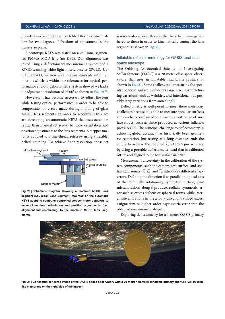
screws push on lever flexures that have ball bearings ad-hered to them in order to kinematically contact the lenssegment as shown in Fig. 20.
Inflatable reflector metrology for OASIS terahertzspace telescopeThe Orbiting Astronomical Satellite for InvestigatingStellar Systems (OASIS) is a 20-meter class space obser-vatory that uses an inflatable membrane primary asshown in Fig. 21. Some challenges to measuring the spec-ular concave surface include its large size, manufactur-ing variations such as wrinkles, and intentional but pos-sibly large variations from annealing58.
λ/8 ≈ 67.5 μm
Deflectometry is well-posed to meet these metrologychallenges because it is able to measure specular surfacesand can be reconfigured to measure a vast range of sur-face slopes, such as those produced at various inflationpressures59,60. The principal challenge to deflectometry inachieving global accuracy has historically been geomet-ric calibration, but testing at a long distance lends theability to achieve the required accuracyby using a portable deflectometer head that is calibratedoffsite and aligned to the test surface in-situ24.
⇀rc,⇀rm,
⇀rsz
z
x y
Measurement uncertainty in the calibration of the sys-tem components, such the camera, test surface, and spa-tial light source, and , introduces different shapeerrors. Defining the direction as parallel to optical axisof the nominally rotationally symmetric surface, axialmiscalibrations along produces radially symmetric er-ror such as excess defocus or spherical terms, while later-al miscalibrations in the or directions embed excessastigmatism or higher order asymmetric error into theobtained measurement shape61.
Exploring deflectometry for a 1-meter OASIS primary
Mock lens segment Flexure
Set screw
Helical coupling
Stepper motor
Fig. 20 | Schematic diagram showing a mock-up MODE lenssegment (i.e., Mock Lens Segment) mounted on the automaticKEYS adopting computer-controlled stepper motor actuators tomake closed-loop orientation and position adjustments (i.e.,alignment and co-phasing) to the mock-up MODE lens seg-ments.
Fig. 21 | Conceptual rendered image of the OASIS space observatory with a 20-metrer diameter inflatable primary aperture (yellow disk-like membrane on the right side of the image).
Opto-Electron Adv 4, 210040 (2021) https://doi.org/10.29026/oea.2021.210040
210040-16
εz
λ/8
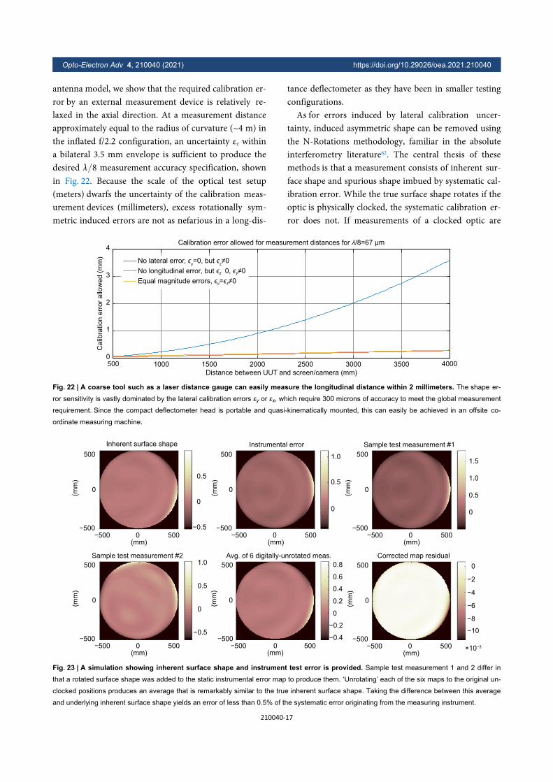
antenna model, we show that the required calibration er-ror by an external measurement device is relatively re-laxed in the axial direction. At a measurement distanceapproximately equal to the radius of curvature (~4 m) inthe inflated f/2.2 configuration, an uncertainty withina bilateral 3.5 mm envelope is sufficient to produce thedesired measurement accuracy specification, shownin Fig. 22. Because the scale of the optical test setup(meters) dwarfs the uncertainty of the calibration meas-urement devices (millimeters), excess rotationally sym-metric induced errors are not as nefarious in a long-dis-
tance deflectometer as they have been in smaller testingconfigurations.
As for errors induced by lateral calibration uncer-tainty, induced asymmetric shape can be removed usingthe N-Rotations methodology, familiar in the absoluteinterferometry literature62. The central thesis of thesemethods is that a measurement consists of inherent sur-face shape and spurious shape imbued by systematic cal-ibration error. While the true surface shape rotates if theoptic is physically clocked, the systematic calibration er-ror does not. If measurements of a clocked optic are
500 1000 1500 2000 2500 3000 3500 4000
Distance between UUT and screen/camera (mm)
0
1
2
3
4
Calib
ratio
n e
rror
allo
we
d (
mm
)
Calibration error allowed for measurement distances for λ/8=67 μm
No lateral error, ϵy=0, but ϵ
z≠0
0
0No longitudinal error, but ϵz 0, ϵy≠Equal magnitude errors, ϵy=ϵz≠
Fig. 22 | A coarse tool such as a laser distance gauge can easily measure the longitudinal distance within 2 millimeters. The shape er-
ror sensitivity is vastly dominated by the lateral calibration errors εy or εx, which require 300 microns of accuracy to meet the global measurement
requirement. Since the compact deflectometer head is portable and quasi-kinematically mounted, this can easily be achieved in an offsite co-
ordinate measuring machine.
Inherent surface shape
500
0
(mm
)
−500−500 0
(mm)500
0.5
0
−0.5
500
0
(mm
)
−500−500 0
(mm)500
500
0
(mm
)
−500−500 0
(mm)500
500
0
(mm
)
−500−500 0
(mm)500
500
0
(mm
)
−500−500 0
(mm)500
500
0
(mm
)
−500−500 0
(mm)500 ×10−3
Instrumental error Sample test measurement #1
Sample test measurement #2 Avg. of 6 digitally-unrotated meas. Corrected map residual
1.0
0.5
0
1.5
1.0
0.5
0
0
−2
−4
−6
−8−10
0.8
0.6
0.4
0.2
0
−0.2
−0.4
1.0
0.5
0
−0.5
Fig. 23 | A simulation showing inherent surface shape and instrument test error is provided. Sample test measurement 1 and 2 differ in
that a rotated surface shape was added to the static instrumental error map to produce them. ‘Unrotating’ each of the six maps to the original un-
clocked positions produces an average that is remarkably similar to the true inherent surface shape. Taking the difference between this average
and underlying inherent surface shape yields an error of less than 0.5% of the systematic error originating from the measuring instrument.
Opto-Electron Adv 4, 210040 (2021) https://doi.org/10.29026/oea.2021.210040
210040-17
digitally unrotated and then averaged, rotationally asym-metric terms can be precisely cancelled out. Fig. 23demonstrates this concept by simulating an inherent testshape and systematic error (in mm), measurements ofthe clocked optic, and the asymmetric term removal res-ult. A clocking uncertainty of 0.5 degrees is added intothe 6-rotation simulation to demonstrate its efficacy evenwith physical rotation stages.
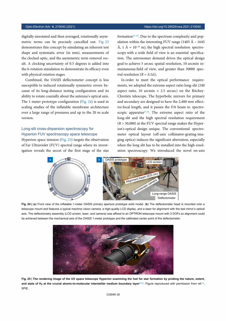
Combined, the OASIS deflectometer concept is lesssusceptible to induced rotationally symmetric errors be-cause of its long-distance testing configuration and itsability to rotate coaxially about the antenna’s optical axis.The 1-meter prototype configuration (Fig. 24) is used inscaling studies of the inflatable membrane architectureover a large range of pressures and up to the 20 m scaleversion.
Long-slit cross-dispersion spectroscopy forHyperion FUV spectroscopy space telescopeHyperion space mission (Fig. 25) targets the observationof Far Ultraviolet (FUV) spectral range where its invest-igation reveals the secret of the first stage of the star
formation63−65. Due to the spectrum complexity and pop-ulation within the interesting FUV range (1405 Å – 1645Å, 1 Å = 10–10 m), the high spectral resolution spectro-scopy with a wide field of view is an essential specifica-tion. The astronomer demand drives the optical designgoal to achieve 5 arcsec spatial resolution, 10 arcmin in-stantaneous field of view, and greater than 30000 spec-tral resolution (R = λ/Δλ).
In order to meet the optical performance require-ments, we adopted the extreme aspect ratio long-slit (240aspect ratio, 10 arcmin × 2.5 arcsec) on the Ritchey-Chretién telescope. The hyperbolic mirrors for primaryand secondary are designed to have the 2,400 mm effect-ive focal length, and it passes the F/6 beam to spectro-scopic apparatus25,26. The extreme aspect ratio of thelong-slit and the high spectral resolution requirement(R > 30,000) at the FUV spectral range makes the Hyper-ion's optical design unique. The conventional spectro-meter optical layout (off-axis collimator-grating-ima-ging optics) induces the significant aberration, especiallywhen the long slit has to be installed into the high-resol-ution spectroscopy. We introduced the novel on-axis
LCD screen
Long-range OASIS
Deflectometer
Alignment beam (633 nm)
Monoscopic camera
OASIS prototypea b
Fig. 24 | (a) Front view of the inflatable 1-meter OASIS primary aperture prototype solid model. (b) The deflectometer head is mounted onto a
telescope mount and features a typical machine vision camera, a high-quality LCD display, and a laser for alignment with the test mirror’s optical
axis. The deflectometry assembly (LCD screen, laser, and camera) was affixed to an OPTRON telescope mount with 3 DOFs so alignment could
be achieved between the mechanical axis of the OASIS 1-meter prototype and the calibrated center point of the deflectometer.
Fig. 25 | The rendering image of the UV space telescope Hyperion examining the fuel for star formation by probing the nature, extent,and state of H2 at the crucial atomic-to-molecular interstellar medium boundary layer25,26. Figure reproduced with permission from ref.25,
SPIE.
Opto-Electron Adv 4, 210040 (2021) https://doi.org/10.29026/oea.2021.210040
210040-18

layout applying the collimation mirror on-axis throughthe center hole of the first grating (échelle grating), andthe freeform imaging mirrors are embodied (Fig. 26).The elliptical center hole on the échelle grating is de-signed to have zero photon loss by matching the second-ary mirror's obstacle as shown in Fig. 26(a).
The on-axis layout of the primary mirror – secondarymirror – tertiary mirror – first grating (échelle) gives theminimized the field aberration along the slit length66,67.Moreover, the in-plane layout of the first grating(échelle) – cross dispersion grating – two freeform mir-ror – detector allows us to estimate and handle the aber-ration easily. Since the cross dispersion divergence angleafter both gratings is large, the formation of the two free-
form mirrors and surfaces are optimized based on thepreviously reported Type-4 design form approach68.Once the optical design is selected, the diffractive per-formance is evaluated for the entire spectral range. Eventhough the geometric optical optimization carefully se-lects the grating diffraction order and line density, itdoesn’t confirm the spectral efficiency. Furthermore, be-cause the high-order échelle grating has a delicate spec-tral sensitivity, the diffraction efficiency simulation is anessential procedure. Based on the electromagnetic wavepropagation simulation, both gratings’ blaze angles aredetermined to have the best efficiency at the targeting or-der as shown in Fig. 27.
80 mm
From telescope
Slitlocation
Freeformmirror
200 mm
Detector
Cross dispersiongrating
Freeformmirror
Optic axis oftelescope
Collimatingmirror (tertiary)
Ellipticalcenter hole
110
mm
z
y
Echellegrating
a b
Fig. 26 | The cross-dispersion spectroscopy optics layout (b) and beam footprint on the échelle grating plane (a). Figure reproduced with permis-
sion from ref.25, SPIE.
Efficiency (blaze angle θB=38.9°)100
80
Eff
icie
ncy (
%)
60
40
20
140 145
Spectrum 1 Spectrum 2 Spectrum 3
150 155Wavelength λ (nm)
160 165 1700
Order (m)
a
Efficiency (blaze angle θB=13.275°)100
80
Eff
icie
ncy (
%)
60
40
20
140 145
Spectrum 1 Spectrum 2 Spectrum 3
150 155Wavelength λ (nm)
160 165 1700
Order (m)
b
cSpectrum 1
148 nm 156 nm 164 nm
141 nm 148 nm
Slit length
156 nm
Spectrum 2 Spectrum 3(156 nm−164 nm)m=−19
m=−18(148 nm−148 nm)(141 nm−156 nm)
m=−17
m=−2m=−1m=0
Fig. 27 | The diffraction efficiency calculation results for (a) échelle grating and (b) cross dispersion and (c) spectrum distribution on the 52 mm ×
52 mm sensor plane. The three orders of the échelle grating are overlapped, but those are separated by cross dispersion horizontally on the
sensor. The high-order of échelle grating dispersive the spectrum rapidly, and it implements the R >30000. Figure reproduced with permission
from ref.25, SPIE.
Opto-Electron Adv 4, 210040 (2021) https://doi.org/10.29026/oea.2021.210040
210040-19
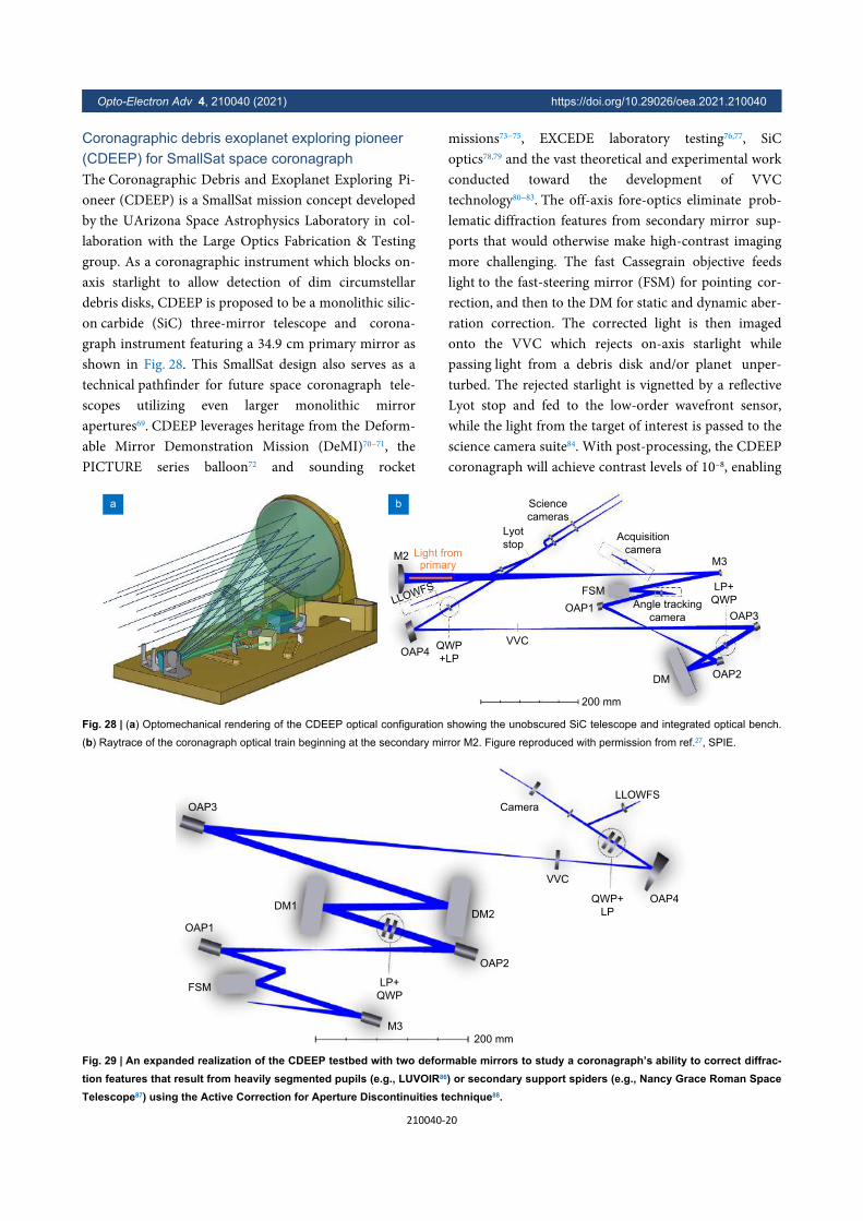
Coronagraphic debris exoplanet exploring pioneer(CDEEP) for SmallSat space coronagraphThe Coronagraphic Debris and Exoplanet Exploring Pi-oneer (CDEEP) is a SmallSat mission concept developedby the UArizona Space Astrophysics Laboratory in col-laboration with the Large Optics Fabrication & Testinggroup. As a coronagraphic instrument which blocks on-axis starlight to allow detection of dim circumstellardebris disks, CDEEP is proposed to be a monolithic silic-on carbide (SiC) three-mirror telescope and corona-graph instrument featuring a 34.9 cm primary mirror asshown in Fig. 28. This SmallSat design also serves as atechnical pathfinder for future space coronagraph tele-scopes utilizing even larger monolithic mirrorapertures69. CDEEP leverages heritage from the Deform-able Mirror Demonstration Mission (DeMI)70−71, thePICTURE series balloon72 and sounding rocket
missions73−75, EXCEDE laboratory testing76,77, SiCoptics78,79 and the vast theoretical and experimental workconducted toward the development of VVCtechnology80−83. The off-axis fore-optics eliminate prob-lematic diffraction features from secondary mirror sup-ports that would otherwise make high-contrast imagingmore challenging. The fast Cassegrain objective feedslight to the fast-steering mirror (FSM) for pointing cor-rection, and then to the DM for static and dynamic aber-ration correction. The corrected light is then imagedonto the VVC which rejects on-axis starlight whilepassing light from a debris disk and/or planet unper-turbed. The rejected starlight is vignetted by a reflectiveLyot stop and fed to the low-order wavefront sensor,while the light from the target of interest is passed to thescience camera suite84. With post-processing, the CDEEPcoronagraph will achieve contrast levels of 10–8, enabling
M2
LLOWFS
OAP4QWP
+LP
VVC
Lyot
stop
OAP1OAP3
OAP2DM
Acquisition
camera
Angle tracking
camera
FSM
M3
Science
cameras
Light fromprimary
200 mm
LP+
QWP
a b
Fig. 28 | (a) Optomechanical rendering of the CDEEP optical configuration showing the unobscured SiC telescope and integrated optical bench.
(b) Raytrace of the coronagraph optical train beginning at the secondary mirror M2. Figure reproduced with permission from ref.27, SPIE.
OAP3
OAP1
FSM
DM1
LP+
QWP
M3
200 mm
OAP2
DM2
VVC
QWP+
LP
Camera
LLOWFS
OAP4
Fig. 29 | An expanded realization of the CDEEP testbed with two deformable mirrors to study a coronagraph’s ability to correct diffrac-tion features that result from heavily segmented pupils (e.g., LUVOIR86) or secondary support spiders (e.g., Nancy Grace Roman SpaceTelescope87) using the Active Correction for Aperture Discontinuities technique88.
Opto-Electron Adv 4, 210040 (2021) https://doi.org/10.29026/oea.2021.210040
210040-20

the direct detection of debris disks and exoplanets27.To prototype this mission and develop a platform for
exploring future high-contrast imaging concepts, a vacu-um-compatible testbed based on the optical layout ofCDEEP (Fig. 29) is under construction at the Universityof Arizona. This testbed will serve as the primaryplatform for testing the CDEEP mission concept, as wellas investigations into VVC technology and electric fieldconjugation focal plane wavefront sensing85. The high-performance and compact form factor are ideal for pro-totyping future high-contrast imaging instrumentationintended for spaceborne observatories. Presently, the op-tical and mechanical design of the testbed are completed,and construction is slated to begin in 2021. The testbedwill begin operations in a cleanroom environment, butultimately be integrated into a vacuum chamber for fur-ther testing and refinement in a relevant environment.The development of the CDEEP testbed marks the be-ginning of The University of Arizona’s journey to devel-oping high-performance optical satellite payloads in sup-port of space astrophysics and planetary science investig-ations.
Concluding remarkA diverse selection of ground-based and space-based fu-ture telescope technologies are actively being conceptual-ized, designed, prototyped, and demonstrated at the Uni-versity of Arizona. Optical polishing enhancements dis-cussed in Section Deterministic computer controlled op-tical surfacing technologies enable efficient productionof future optical elements. New engineering technologyin Section Very large telescope control system, instru-ment, and segmentation will upgrade and expand capab-ilities of existing very large ground-based or space tele-scopes. Finally, in Section Future space telescope con-cepts and enabling technologies, a view of the futureshows how space-based telescopes that had previouslybeen only a dream, are now realizable through the ad-vances in optical engineering technologies. This suite ofoptical technologies serves the next generation of astro-nomical investigations by offering novel yet applicableapproaches that the wider design and engineering com-munity can practically use. It is our hope that these con-tributions in design and instrumentation will not onlyprovide new practical benchmarks for modern astro-nomy today, but also precipitate the next great insightsand questions about our universe.
References Martin HM, Allen RG, Burge JH, Kim DW, Kingsley JS et al.Fabrication and testing of the first 8.4-m off-axis segment forthe Giant Magellan Telescope. Proc SPIE 7739, 77390A(2010).
1.
Martin HM, Allen RG, Burge JH, Kim DW, Kingsley JS et al.Production of 8.4m segments for the Giant Magellan Tele-scope. Proc SPIE 8450, 84502D (2012).
2.
Martin HM, Burge JH, Davis JM, Kim DW, Kingsley JS et al.Status of mirror segment production for the Giant MagellanTelescope. Proc SPIE 9912, 99120V (2016).
3.
Martin HM, Allen R, Gasho V, Jannuzi BT, Kim DW et al. Man-ufacture of primary mirror segments for the Giant MagellanTelescope. Proc SPIE 10706, 107060V (2018).
4.
Kim DW, Kim SW, Burge JH. Non-sequential optimization tech-nique for a computer controlled optical surfacing process us-ing multiple tool influence functions. Opt Express 17,21850–21866 (2009).
5.
Ke XL, Wang TY, Choi H, Pullen W, Huang L et al. Dual-toolmultiplexing model of parallel computer controlled optical sur-facing. Opt Lett 45, 6426–6429 (2020).
6.
Kim DW, Park WH, Kim SW, Burge JH. Edge tool influencefunction library using the parametric edge model for computercontrolled optical surfacing. Proc SPIE 7426, 74260G (2009).
7.
Negi VS, Garg H, Shravan Kumar RR, Karar V, Tiwari UK et al.Parametric removal rate survey study and numerical modelingfor deterministic optics manufacturing. Opt Express 28,26733–26749 (2020).
8.
Wang TY, Huang L, Kang H, Choi H, Kim DW et al. RIFTA: arobust iterative Fourier transform-based dwell time Algorithmfor ultra-precision ion beam figuring of synchrotron mirrors. SciRep 10, 8135 (2020).
9.
Wang TY, Huang L, Zhu Y, Vescovi M, Khune D et al. Devel-opment of a position–velocity–time-modulated two-dimension-al ion beam figuring system for synchrotron x-ray mirror fabric-ation. Appl Opt 59, 3306–3314 (2020).
10.
Rodriguez S, Rakich A, Hill J, Kuhn O, Brendel T et al. Imple-mentation of a laser-truss based telescope metrology systemat the Large Binocular Telescope. Proc SPIE 11487, 114870E(2020).
11.
Rakich A, Choi H, Veillet C, Hill JM, Bec M et al. A laser-trussbased optical alignment system on LBT. Proc SPIE 11445,114450R (2020).
12.
Kang H, Thompson D, Conrad A, Vogel C, Lamdan A et al.Modular plug-in extension enabling cross-dispersed spectro-scopy for Large Binocular Telescope. Proc SPIE 11116,1111606 (2019).
13.
Feng YT, Ashcraft JN, Breckinridge JB, Harvey JE, DouglasES et al. Topological pupil segmentation and point spreadfunction analysis for large aperture imaging systems. ProcSPIE 11568, 115680I (2020).
14.
Apai D, Milster TD, Kim DW, Bixel A, Schneider G et al. Athousand earths: a very large aperture, ultralight space tele-scope array for atmospheric biosignature surveys. Astron J
15.
Opto-Electron Adv 4, 210040 (2021) https://doi.org/10.29026/oea.2021.210040
210040-21
158, 83 (2019). Apai D, Milster TD, Arenberg J, Kim D, Liang R et al. Nautilusdeep space observatory: a giant segmented space telescopearray for a galactic biosignature survey. In Deep Space Gate-way Concept Science Workshop 3127 (LPI, 2018). Bibcode:2018LPICo2063.3127A
16.
Apai D, Milster TD, Kim DW, Bixel A, Schneider G et al.Nautilus Observatory: a space telescope array based on verylarge aperture ultralight diffractive optical elements. Proc SPIE11116, 1111608 (2019).
17.
Milster TD, Apai D, Kim DW, Kim YS, Kim GH et al. Progresstoward optical design and fabrication of ultralight, large aper-ture transmissive lenses for space telescopes. In Frontiers inOptics 2020 FM1A.2 (OSA, 2020); https://doi.org/10.1364/FIO.2020.FM1A.2.
18.
Kim DW, Walker CK, Apai D, Milster TD, Takashima Y et al.Disruptive space telescope concepts, designs, and develop-ments: OASIS and Nautilus -INVITED. EPJ Web Conf 238,06001 (2020).
19.
Esparza MA, Choi H, Kim DW. Alignment of Multi-Order Dif-fractive Engineered (MODE) lens segments using the Kinemat-ically-Engaged Yoke System. Proc SPIE 11487, 114870V(2020).
20.
Choi H, Esparza MA, Lamdan A, Feng TT, Milster T et al. In-process metrology for segmented optics UV curing control.Proc SPIE 11487, 114870M (2020).
21.
Walket CK, Smith IS, Goldsmith PF, O’Dougherty S, Takashi-ma Y et al. Spherical reflectors for space based telescopes. InProceedings of 2017 IEEE MTT-S International MicrowaveSymposium (IMS) 1884 –1887 (IEEE, 2017); https://doi.org/10.1109/MWSYM.2017.8059024.
22.
Chandra A, Sirsi S, Choi H, Phan A, Takashima Y et al.Thermally formed inflatable reflectors for space telescopes. InProceedings of 2020 IEEE Aerospace Conference 1–9 (IEEE,2020); https://doi.org/10.1109/AERO47225.2020.9172651.
23.
Quach H, Berkson J, Sirsi S, Choi H, Dominguez R et al. Full-aperture optical metrology for inflatable membrane mirrors.Proc SPIE 11487, 114870N (2020).
24.
Choi H, Trumper IL, Feng YT, Kang H, Berkson J et al. Long-slit cross-dispersion spectroscopy for Hyperion UV space tele-scope. J Astron Telesc, Instrum, Syst 7, 014006 (2021).
25.
Choi H, Trumper I, Feng YT, Kang H, Hamden E et al. Hyper-ion: far-UV cross dispersion spectroscope design. Proc SPIE11487, 114870W (2020).
26.
Maier ER, Douglas ES, Kim DW, Su K, Ashcraft JN et al.Design of the vacuum high contrast imaging testbed forCDEEP, the Coronagraphic Debris and Exoplanet ExploringPioneer. Proc SPIE 11443, 114431Y (2020).
27.
Kim DW, Esparza M, Quach H, Rodriguez S, Kang H et al. Op-tical technology for future telescopes. Proc SPIE 11761,1176103 (2021).
28.
Cheng H. Independent Variables for Optical Surfacing Sys-tems: Synthesis, Characterization and Application. (Springer-Verlag, Berlin, 2014).
29.
Carnal CL, Egert CM, Hylton KW. Advanced matrix-based al-30.
gorithm for ion-beam milling of optical components. Proc SPIE1752, 54–62 (1992). Wu JF, Lu ZW, Zhang HX, Wang TS. Dwell time algorithm inion beam figuring. Appl Opt 48, 3930–3937 (2009).
31.
Huang T, Zhao D, Cao ZC. Trajectory planning of optical pol-ishing based on optimized implementation of dwell time. Pre-cis Eng 62, 223–231 (2020).
32.
Zhou L, Dai YF, Xie XH, Jiao CJ, Li SY. Model and method todetermine dwell time in ion beam figuring. Nanotechnol PrecisEng 5, 107–112 (2007).
33.
Zhang YF, Fang FZ, Huang W, Fan W. Dwell time algorithmbased on bounded constrained least squares under dynamicperformance constraints of machine tool in deterministic optic-al finishing. Int J Precis Eng Manuf-Green Technol (2021).
34.
Jiao CJ, Li SY, Xie XH. Algorithm for ion beam figuring of low-gradient mirrors. Appl Opt 48, 4090–4096 (2009).
35.
Wilson SR, McNeil JR. Neutral ion beam figuring of large optic-al surfaces. Proc SPIE 0818, 320–324 (1987).
36.
Wang TY, Huang L, Vescovi M, Kuhne D, Tayabaly K et al.Study on an effective one-dimensional ion-beam figuring meth-od. Opt Express 27, 15368–15381 (2019).
37.
Richardson WH. Bayesian-based iterative method of imagerestoration. J Opt Soc Am 62, 55–59 (1972).
38.
Nelder JA, Mead R. A simplex method for function minimiza-tion. Comput J 7, 308–313 (1965).
39.
Huang L, Wang TY, Tayabaly K, Kuhne D, Xu WH et al. Stitch-ing interferometry for synchrotron mirror metrology at NationalSynchrotron Light Source II (NSLS-II). Opt Lasers Eng 124,105795 (2020).
40.
Huang L, Wang TY, Nicolas J, Vivo A, Polack F et al. Two-di-mensional stitching interferometry for self-calibration of high-order additive systematic errors. Opt Express 27,26940–26956 (2019).
41.
Heidt J, Thompson D. LUCI Users Manual. September 7, 2016https://sites.google.com/a/lbto.org/luci/documents-and-links.
42.
Werenskiold CH. Improved telescope spider design. J Roy As-tron Soc Can 35, 268 (1941).
43.
Couder A. Dealing with spider diffraction. In Amateur Tele-scope Making (Book Two), Ingalls AG, ed, 8th Printing620–622 (Scientific American, Inc, 1952).
44.
Everhart E, Kantorski JW. Diffraction patterns produced by ob-structions in reflecting telescopes of modest size. Astron J 64,455 (1959).
45.
Richter JL. Spider diffraction: a comparison of curved andstraight legs. Appl Opt 23, 1907–1913 (1984).
46.
Harvey JE, Ftaclas C. Diffraction effects of telescope second-ary mirror spiders on various image-quality criteria. Appl Opt34, 6337–6349 (1995).
47.
Kasdin NJ, Vanderbei RJ, Spergel DN, Littman MG. Extrasolarplanet finding via optimal apodized-pupil and shaped-pupilcoronagraphs. Astrophys J 582, 1147–1161 (2003).
48.
Breckinridge JB, Harvey JE, Crabtree K, Hull T. Exoplanet tele-scope diffracted light minimized: the pinwheel-pupil solution.Proc SPIE 10698, 106981P (2018).
49.
Snik F, Absil O, Baudoz P, Beaulieu M, Bendek E et al.50.
Opto-Electron Adv 4, 210040 (2021) https://doi.org/10.29026/oea.2021.210040
210040-22
Review of high-contrast imaging systems for current and fu-ture ground-based and space-based telescopes III: techno-logy opportunities and pathways. Proc SPIE 10706, 107062L(2018). Breckinridge JB, Harvey JE, Irvin R, Chipman R, Kupinski M etal. ExoPlanet Optics: conceptual design processes for stealthtelescopes. Proc SPIE 11115, 111150H (2019).
51.
Harvey JE, Breckinridge JB, Irvin RG, Pfisterer RN. Noveldesigns for minimizing diffraction effects of large segmentedmirror telescopes. Proc SPIE 10745, 107450L (2018).
52.
Perrin M, Long J, Douglas E, Sivaramakrishnan A, Slocum Cet al. POPPY: physical optics propagation in PYthon. Astro-physics Source Code Library, record ascl: 1602.018 (2016).
53.
Perrin MD, Soummer R, Elliott EM, Lallo MD, Sivaramakrish-nan A. Simulating point spread functions for the James WebbSpace Telescope with WebbPSF. Proc SPIE 8442, 84423D(2012).
54.
Ruane G, Riggs A, Coker CT, Shaklan SB, Sidick E et al. FastLinearized Coronagraph Optimizer (FALCO) IV: coronagraphdesign survey for obstructed and segmented apertures. Proc
SPIE 10698, 106984U (2018).
55.
N’Diaye M, Soummer R, Pueyo L, Carlotti A, Stark CC et al.Apodized pupil lyot coronagraphs for arbitrary apertures. Astro-
phys J 818, 163 (2016).
56.
Kim Y, Wang ZC, Milster T. Ultralight very large aperture spacetelescopes using MODE lens technology. In Optical Designand Fabrication 2019 FM4B.4 (OSA, 2019).https://doi.org/10.1364/FREEFORM.2019.FM4B.4.
57.
Walker C, Kulesa C, Smith IS, Perry B, Takashima Y et al. Or-biting Astronomical Satellite for Investigating Stellar Systems(OASIS): following water from the interstellar medium tooceans. Bulletin of the AAS [Internet]. 2019 Sep 30;51(7). ht-tps://baas.aas.org/pub/2020n7i047.
58.
Knauer MC, Kaminski J, Hausler G. Phase measuring deflec-tometry: a new approach to measure specular free-form sur-faces. Proc SPIE 5457, 366–376 (2004).
59.
Su P, Parks RE, Wang LR, Angel RP, Burge JH. Software con-figurable optical test system: a computerized reverse Hart-mann test. Appl Opt 49, 4404–4412 (2010).
60.
Su TQ, Wang SS, Parks RE, Su P, Burge JH. Measuring roughoptical surfaces using scanning long-wave optical test system.Appl Opt 52, 7117–7126 (2013).
61.
Evans CJ, Kestner RN. Test optics error removal. Appl Opt 35,1015–1021 (1996).
62.
Decataldo D, Pallottini A, Ferrara A, Vallini L, Gallerani S. Pho-toevaporation of jeans-unstable molecular clumps. Mon Not
Roy Astron Soc 487, 3377–3391 (2019).
63.
Gould RJ, Salpeter EE. The interstellar abundance of the hy-drogen molecule. I. Basic processes. Astrophys J 138, 393(1963).
64.
Krumholz MR. The big problems in star formation: the starformation rate, stellar clustering, and the initial mass function.Phys Rep 539, 49–134 (2014).
65.
Smith WJ. Modern Lens Design 2nd ed (McGraw-Hill, NewYork, 2005).
66.
Shannon RR. The Art and Science of Optical Design (Cam-bridge University Press, Cambridge, 1997).
67.
Trumper I, Anderson AQ, Howard JM, West G, Kim DW.Design form classification of two-mirror unobstructed freeformtelescopes. Opt Eng 59, 025105 (2020).
68.
West SC, Bailey SH, Bauman S, Cuerden B, Granger Z et al. Aspace imaging concept based on a 4m structured spun-castborosilicate monolithic primary mirror. Proc SPIE 7731,77311O (2010).
69.
Allan G, Douglas ES, Barnes D, Egan M, Furesz G et al. Thedeformable mirror demonstration mission (DeMi) CubeSat: op-tomechanical design validation and laboratory calibration. ProcSPIE 10698, 1069857 (2018).
70.
Morgan RE, Douglas ES, Allan GW, Bierden P, Chakrabarti Set al. MEMS deformable mirrors for space-based high-contrastimaging. Micromachines 10, 366 (2019).
71.
Mendillo CB, Howe GA, Hewawasam K, Martel J, Finn SC etal. Optical tolerances for the PICTURE-C mission: error budgetfor electric field conjugation, beam walk, surface scatter, andpolarization aberration. Proc SPIE 10400, 1040010 (2017).
72.
Mendillo CB, Hicks BA, Cook TA, Bifano TG, Content DA et al.PICTURE: a sounding rocket experiment for direct imaging ofan extrasolar planetary environment. Proc SPIE 8442, 84420E(2012).
73.
Chakrabarti S, Mendillo CB, Cook TA, Martel JF, Finn SC et al.Planet Imaging Coronagraphic Technology Using a Reconfig-urable Experimental Base (PICTURE-B): the second in theseries of suborbital exoplanet experiments. J Astron Inst 5,1640004 (2016).
74.
Douglas ES, Mendillo CB, Cook TA, Cahoy KL, Chakrabarti S.Wavefront sensing in space: flight demonstration II of the PIC-TURE sounding rocket payload. J Astron Telesc, Instrum, Syst4, 019003 (2018).
75.
Belikov R, Lozi J, Pluzhnik E, Hix TT, Bendek E et al. EX-CEDE technology development III: first vacuum tests. ProcSPIE 9143, 914323 (2014).
76.
Sirbu D, Thomas SJ, Belikov R, Lozi J, Bendek E et al. EX-CEDE technology development IV: demonstration of polychro-matic contrast in vacuum at 1.2 λ/D. Proc SPIE 9605, 96050J(2015).
77.
Tinker F, Ragan C, Bodden A, Dahlberg K. 2016. SiliconCarbide Optical Telescopes in “Small Satellite” Constellations.AIAA/USU Conference on Small Satellites, August.https://digitalcommons.usu.edu/smallsat/2016/Poster3/4.
78.
Tinker F, Xin K. Fabrication of SiC aspheric mirrors with lowmid-spatial error. Proc SPIE 8837, 88370M (2013).
79.
Mawet D, Serabyn E, Liewer K, Hanot C, McEldowney S et al.Optical vectorial vortex coronagraphs using liquid crystal poly-mers: theory, manufacturing and laboratory demonstration. OptExpress 17, 1902–1918 (2009).
80.
Mawet D, Serabyn E, Liewer K, Burruss R, Hickey J et al. Thevector vortex coronagraph: laboratory results and first light atPalomar observatory. Astrophys J 709, 53–57 (2010).
81.
Ruane G, Crill B, Patterson K, Prada CM, Seo BJ et al.Decadal survey testbed commissioning roadmap: demonstrating
82.
Opto-Electron Adv 4, 210040 (2021) https://doi.org/10.29026/oea.2021.210040
210040-23
technology for imaging new worlds. Jet Propulsion Laboratory,NASA ExEP Program roadmap, 11 (2019). Serabyn G, Mawet D, Ruane G, Mejia-Prada C, Jovanovic N.Technology development for exoplanet MISSONS: technologymilestone white paper vortex coronagraph technology. TDEMWhite Paper, JPL TDEM Whitepaper (2019).
83.
Singh G, Martinache F, Baudoz P, Guyon O, Matsuo T et al.Lyot-based low order wavefront sensor for phase-maskcoronagraphs: principle, simulations and laboratory experi-ments. Publ Astron Soc Pac 126, 586–594 (2014).
84.
Belikov R, Give’on A, Kern B, Cady E, Carr M et al. Demon-stration of high contrast in 10% broadband light with theshaped pupil coronagraph. Proc SPIE 6693, 66930Y (2007).
85.
Pueyo L, Stark C, Juanola-Parramon R, Zimmerman N, BolcarM et al. The LUVOIR Extreme Coronagraph for Living Planet-ary Systems (ECLIPS) I: searching and characterizing exo-planetary gems. Proc SPIE 11117, 1111703 (2019).
86.
Kasdin NJ, Bailey VP, Mennesson B, Zellem RT, Ygouf M etal. The Nancy grace roman space telescope coronagraph in-strument (CGI) technology demonstration. Proc SPIE 11443,114431U (2020).
87.
Mazoyer J, Pueyo L. Fundamental limits to high-contrast wave-front control. Proc SPIE 10400, 1040014 (2017).
88.
AcknowledgementsThe authors would like to acknowledge the Gordon and Betty MooreFoundation for their financial support of the development of the MODE
lens and its enabling alignment technologies. Also, we would like to ac-knowledge the II-VI Foundation Block-Gift, Technology Research Initiat-ive Fund Optics/Imaging Program, and Friends of Tucson Optics EndowedScholarships in Optical Sciences for helping support the optical design andmetrology research conducted in the LOFT group. We also thank Prof. GregSmith for his technical and editorial inputs and helps during the manuscriptwriting process.
Author contributionsD. Kim supervised/co-supervised the overall optical engineering projectspresented in this review summary paper. H. Choi co-supervised overallprojects including the LBT prime focus camera alignment using laser trussalignment system and the Nautilus MODE lens segment UV curing system,and designed the long-slit cross-dispersion spectroscopy of Hyperion spacetelescope. T. Brendel co-developed and summarized the LBT prime focuscamera alignment methodology using laser truss alignment system. H.Quach co-developed the OASIS inflatable reflector metrology system for theterahertz very large space observatory. M. Esparza co-developed theNautilus segmented transmissive optics alignment technology for MODElens. H. Kang co-designed and assembled the LBT MOBIUS cross-disper-sion unit. Y. T. Feng performed the pupil segmentation topology simula-tions and investigated the point spread functions. J. N. Ashcraft co-de-signed the CDEEP space coronagraph telescope’s optical system and itsTVAC testbed system. X. L. Ke and T. Y. Wang researched and co-investig-ated the CCOS run multiplexing theory and dwell time optimization al-gorithm. E. S. Douglas is the PI of the CDEEP project and co-edited this re-view summary manuscript with D. Kim.
Competing interestsThe authors declare no competing financial interests.
Opto-Electron Adv 4, 210040 (2021) https://doi.org/10.29026/oea.2021.210040
210040-24