advancing engineering frontiers€¢ project management • experimental design • investigative...
TRANSCRIPT

Integrity Management
AdvancingEngineeringFrontiers

C-FERTechnologies Printed September 2015

For over 30 years, C-FER Technologies has created innovative technologies and developed
new processes for the energy, transportation and manufacturing industries that have reduced
costs, increased revenues, extended the life of systems and ensured regulatory compliance.
C-FER holds patents and intellectual property rights to dozens of energy industry products and processes including revolutionary Downhole Oil/Water Separation technology, PC-PUMP® software, CalTranTM software, PIRAMID™ software and more. C-FER offers state-of-the-art structural, mechanical and reliability engineering expertise in the following areas:
Corporate Profile
C-FERTechnologies
www.cfertech.com
• Project Management • Experimental Design • Investigative Engineering • Computer Modeling • Prototype Design and Manufacture • Failure Analysis/Structural Testing
• Production Engineering • Limit States Design • Software Development • Solid Mechanics • Field Services • Risk and Reliability Engineering
The C-FER Advantage When there is a lot at risk, operators and suppliers alike rely on C-FER’s third party, independent verification methodology. Whether you are pushing the boundaries of technology, optimizing design, or quantifying reliability, C-FER’s expertise and one-of-a-kind facility can meet your performance qualification requirements.
For energy producers who use technology for strategic advantage, C-FER’s innovation expertise is a powerful resource for improving profitability and safety. Our know-how extends beyond applied research to include collaboration with manufacturers and service companies to ensure the viable commercialization of new energy industry products and services.
One of the keys to successfully bringing new technologies to market lies in the ability to perform tests at full scale, simulated within a controlled environment.
C-FER’s world class laboratory services offer a powerful combination of testing and analysis tools designed to accommodate a vast range of applied research to meet energy industry requirements. C-FER has the know-how to make solutions work in the real world.
For more information on our products and services visit
Real World Solutions

Risk and Reliability
C-FERTechnologies
Expertise• Risk Assessment and Management • Integrity Management, Planning and Optimization • Structural and Mechanical Reliability Analysis • Release Consequence Modeling and Evaluation • Probabilistic Modeling of Loads and System Response • Decision Analysis Uncertainty
Applications• Maintenance planning including segment ranking and optimization of maintenance activities • Planning of hydrostatic and inspection intervals and repair schedules • Regulatory exceptions including pressure uprating and class upgrade deferrals • Design of arctic, high strength and deep water pipelines
Software• PIRAMID–a comprehensive quantitative risk-based pipeline maintenance planning and optimization tool for onshore and offshore pipelines • PRISM–a reliability estimation tool for the key threats affecting pipeline design and assessment decisions
Predicted Failure Rate as a Function of Time
Risk Ranking Matrix
Immediate Action
Scheduled Action
No Action
Total Risk Profile
www.cfertech.com

C-FERTechnologies
PIRAMID™PIRAMID Worldwide Applications
www.cfertech.com

Excavated pipe subject to ground movement and its associated analyis model
C-FERTechnologies
Strain–Based DesignPipe–Soil Interaction Models• Loads induced on buried pipeline by ground movement
(frost heave, thaw subsidence, slope failure, and seismic action)
• Interaction of pipeline and soil characterized using 2D or 3D soil-spring models
• Finite Element Analysis simulates elastic-plastic response of pipe
• Output determines demand on compressive and tensile strains
Compressive Strain Limits• Critical buckling strain defined as a function of D/t, internal pressure and stress-strain curve
• Can be established using empirical equations, finite element analyses and large-scale testing
Tensile Strain Limits• Tensile strain capability limited by girth weld defects or weld mismatch
• Can be established by curved wide plate tests, biaxial tests, finite element analysis, and empirical equations
www.cfertech.com
3.0%
2.5%
2.0%
1.5%
1.0%
0.5%
0.0%20 40 60 80 100C
ompr
essi
ve S
trai
n Li
mit
D/t
high internal pressurelow internal pressureno internal pressure
0
1
2
3
4
5
6
7
0.0% 0.5% 1.0% 1.5% 2.0% 2.5% 3.0% 3.5%
8 mm flaw7 mm flaw6 mm flaw5 mm flaw
CM
OD
(mm
)
Tesile Strain
Finite element simulation of weld flaw openingCompressive Strain Limit as a function of D/t and pressure

LOAD FRAMES C-FER operates a variety of large-scale servo-hydraulic load frames to simulate complex loading scenarios representative of field conditions.
Auxiliary Equipment Example Tests
• Electric resistive or inductive heating systems • Hydrotest equipment• High pressure cooling system • Leak detection equipment• Bending systems• Torsion systems• Pass-through pressure vessels
• ISO / Thermal well casing connections • Biaxial Tension/Compression of line pipe• Four-point bend of line pipe • Wave loading on composite risers• Makeup of subsea pipeline collets• Drilling top drive assemblies • Crack growth in aerospace structural panels• Seismic building dampers
System Universal Testing System Tubular Testing System
Connection Testing System
Horizontal Testing System
Maximum Specimen Dimensions
Length 6 mBase 2 x 18 m
Length 15 mDiameter 1.5 m
Length 11.6 mBase 2 x 2 m
Length 5.5 mDiameter 1.2 m
System can be reconfigured to accept larger specimens
Maximum Load
Compression 15 MNTension 15 MNDynamic 5 MN
Structurally capable of 22 MN with additional actuators
Compression 15 MNTension 15 MN
Compression 15 MNTension 15 MN
Tension 71 MN
Frame Orientation
Vertical Vertical Vertical Horizontal
Special Features
Maximum stroke rate 100 mm/sec
Bending capacity of 27 MNm
Bending capacity 27 MNm
Bending capacity 8 MNm
Sour service capability
Energy dissipation system for destructive testing
Laboratory Facilities
Laboratory Facilities
C-FERTechnologies
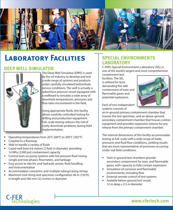
DEEP WELL SIMULATOR The Deep Well Simulator (DWS) is used by the oil industry to develop and test a wide range of systems and products under carefully simulated bottomhole service conditions. The well is actually a subsurface pressure vessel equipped with a wellhead to simulate a wide array of downhole temperatures, pressures and flow rates encountered in the field.
Using appropriate fluids, this facility allows carefully controlled testing for drilling and production equipment. Full–scale testing reduces the risk of costly downhole problems during field implementation.
• Operating temperatures from 20°C (68°F) to 200°C (392°F) • Coupled to a flowloop • Able to handle a variety of fluids • Cased well bore 0.6 metres (2 feet) in diameter, providing 14 MPa (2,000 psi) containment capacity • Control tests on pump systems with full pressure fluid mixing (single and two phase), flowmeters, and tankage • Easy access to electric and hydraulic power, fluid handling and instrumentation • Accommodates concentric and multiple tubing/casing strings • Maximum tool string and specimen configuration 46 m (150 ft) in length and 560 mm (22 inches) in diameter
SPECIAL ENVIRONMENTS LABORATORY C-FER’s Special Environments Laboratory (SEL) is one of the world’s largest and most comprehensive containment test facilities. The SEL is utilized for tests demanding the safe containment of toxic and flammable gases and potential explosions.
Each of two independent systems consists of an in-ground primary containment chamber that houses the test specimen, and an above-ground secondary containment chamber that houses control equipment and provides expansion volume for any release from the primary containment chamber.
The internal dimensions of this facility accommodate testing at full–scale with a wide range of loads, pressures and fluid flow conditions, yielding results that are more representative of processes occurring under real field conditions.
• Twin in-ground test chambers provide secondary containment for toxic and flammable gases, with capacity to fully contain explosions • Simulation of corrosive and flammable environments, including flow • External remote control of test systems • Sealable below-ground test vessel, 12 m deep x 2.5 m diameter
www.cfertech.com

Laboratory Facilities
C-FERTechnologies
EXPERIMENTAL FLOW LOOP The Experimental Flow Loop is used to test the performance of downhole pumping systems over a range of operating temperatures, pressures, flowrates and gas/liquid ratios.
The flow loop consists of an 85 ft long, 244.5 mm OD (9 5/8”, 40 lb/ft), casing section; separator; and heating and cooling equipment.
Physical Setup • Accommodates downhole- and surface- driven pump systems up to 24.4 m (80 ft) in length, up to 12 m (40 ft) per section; • Allows for downhole gas (steam and air) separation at the pump intake with a simulated submergence of approximately 2 m (6.6 ft); • 11” 3000# API wellhead flange which allows for a variety of standard wellheads to be installed. • Fully instrumented to allow real time pressure, temperature, flow measurements and pump torque and speed.
Pressure and Temperature Limits • Pump intake pressure from 100 kPag to 4140 kPag (15-600 psig); • Pump discharge pressure to 7580 kPag (1100 psig); • Pump intake temperature from 60°C to 200°C (140-400°F).
Volumetric Capacity • Liquid flow rate up to 800 m3/d (5050 bpd) – Water, oil or oil/water mixture • Air injection up to 120 std-m3/h (70 scfm) at 4140 kPag (600 psig) at the downhole pump intake.
www.cfertech.com

Laboratory Facilities
C-FERTechnologies
DEEPWATER EXPERIMENTAL CHAMBER C-FER’s Deepwater Experimental Chamber (DEC) enables full-scale testing of deepwater pipeline and production equipment. The vessel is unique because of the size, pressure rating and ease of access. Equipped with quick release end caps, the vessel ensures rapid installation and removal of equipment, reducing both testing time and cost.
Full-scale tests with comprehensive instrumentation, control and video monitoring minimizes the potential for costly equipment failures in deep water.
• Working pressures to 55 MPa (8,000 psi) • 10.7 m (35 ft) long with a 1.22 m (4 ft) diameter • Equipped with internal rams and reaction frames to apply tension, compression, torsion and bending loads to specimens while under pressure • Full–scale pipeline testing at working pressures, both internally and externally • Rapid installation and removal of test specimens and assemblies • Internal video monitoring • Accommodates hydraulic, electrical, video and instrumentation leads
www.cfertech.com
STRONG FLOOR AND WALLS • High capacity multi-use reaction floor (22 m x 12 m) • Buttressed multi-directional reaction wall (15 m long x 6 m high) for application of multi-directional loading • Accommodates large-scale structural assemblies and components with more than 1,300 tie-down locations • Serviced by 15 tonne overhead travelling crane
COMPONENT TESTING • 1000 kN capacity servohydraulic MTS machine for coupon testing under a variety of load & temperature conditions • 16,200 N-m torsion testing unit, with independently operated axial tensile load capacity to 1,300 kN • Other self-contained computer-controlled load and pressure systems for serviceability and proof testing of hoisting equipment, couplings, valves, vessels, etc.

C-FERTechnologies www.cfertech.com
Contacts MANAGING DIRECTOR
780.450.8989 x253
Francisco Alhanati [email protected]
DRILLING & COMPLETIONS780.450.8989 x236Kirk Hamilton, Manager
EXPLORATION & PRODUCTION
780.450.8989 x246
Kelly Piers, Director [email protected]
ENGINEERING SERVICES 780.450.8989 x299
Paul Skoczylas, Manager [email protected]
PIPELINES & STRUCTURES 587.754.2339 x215
Qishi Chen, Director [email protected]
DESIGN & CONSTRUCTION 587.754.2339 x259
Chris Timms, Manager [email protected]
INTEGRITY & OPERATIONS 587.754.2339 x308
Jason Skow, Manager [email protected]
C-FER FELLOW 780.450.8989 x252
Cam Matthews [email protected]
CHIEF ENGINEER & C-FER FELLOW 587.754.2339 x207
Maher Nessim [email protected]
BUSINESS DEVELOPMENT & PLANNING780.450.8989 x235Brian Wagg, Director [email protected]
PRODUCTION OPERATIONS780.450.8989 x306Wayne Klaczek, Manager [email protected]

C-FERTechnologies
200 Karl Clark Road Edmonton, Alberta Canada T6N 1H2
www.cfertech.com