advisory circular ac91-21 rnav 1, rnav 2, rnp 1, rnp 2 ... · rnav 1, rnav 2, rnp 1, rnp 2, rnp...
TRANSCRIPT

Published by Civil Aviation Authority
PO Box 3555 Wellington 6140
Authorised by
Manager International and Regulatory Strategy
Advisory Circular AC91-21
Revision 0.3
RNAV 1, RNAV 2, RNP 1, RNP 2, RNP APCH and BARO VNAV—Operational Approvals
5 September 2016
General Civil Aviation Authority advisory circulars contain guidance and information about standards, practices, and procedures that the Director has found to be an acceptable means of compliance with the associated rules and legislation.
However the information in the advisory circular does not replace the requirement for participants to comply with their own obligations under the Civil Aviation Rules, the Civil Aviation Act 1990 and other legislation.
An advisory circular reflects the Director’s view on the rules and legislation. It expresses CAA policy on the relevant matter. It is not intended to be definitive. Consideration will be given to other methods of compliance that may be presented to the Director. When new standards, practices, or procedures are found to be acceptable they will be added to the appropriate advisory circular. Should there be any inconsistency between this information and the rules or legislation, the rules and legislation take precedence.
An advisory circular may also include guidance material generally, including guidance on best practice as well as guidance to facilitate compliance with the rule requirements. However, guidance material must not be regarded as an acceptable means of compliance.
An advisory circular may also include technical information that is relevant to the standards or requirements.
Purpose This advisory circular provides an acceptable means of compliance with the airworthiness design standards and operating procedures required to obtain approval by the Director to conduct Performance Based Navigation (PBN) operations under RNP 1, RNP 2, RNAV 1, RNAV 2, RNP APCH and BARO VNAV within New Zealand. Approval by the Director may be granted upon satisfactory assessment of the aircraft navigation system and documented operator procedures, and confirmation of the training and qualification of pilots.

Related Rules This advisory circular relates specifically to the applicable provisions of New Zealand Civil Aviation Rule Part 91.
It also relates to the pilot training and qualification requirements in Parts 61, 119, 121, 125 and 135.
Change Notice Revision 0.3 updates the interim transitional clarification notice for Part 91 participants in regard to gaining RNP 1 approvals. The other content from Revision 0.2 remains unchanged.
Advisory Circular AC91-21 Revision 0.3
5 September 2016 1 CAA of NZ
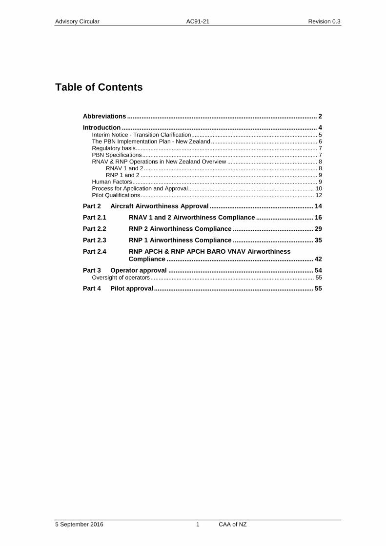
Table of Contents
Abbreviations .......................................................................................................... 2 Introduction ............................................................................................................. 4
Interim Notice - Transition Clarification ............................................................................. 5 The PBN Implementation Plan - New Zealand ................................................................. 6 Regulatory basis ............................................................................................................... 7 PBN Specifications ........................................................................................................... 7 RNAV & RNP Operations in New Zealand Overview ....................................................... 8
RNAV 1 and 2 .......................................................................................................... 8 RNP 1 and 2 ............................................................................................................ 9
Human Factors ................................................................................................................. 9 Process for Application and Approval ............................................................................. 10 Pilot Qualifications .......................................................................................................... 12
Part 2 Aircraft Airworthiness Approval .......................................................... 14 Part 2.1 RNAV 1 and 2 Airworthiness Compliance ................................ 16
Part 2.2 RNP 2 Airworthiness Compliance ............................................. 29
Part 2.3 RNP 1 Airworthiness Compliance ............................................. 35
Part 2.4 RNP APCH & RNP APCH BARO VNAV Airworthiness Compliance .................................................................................. 42
Part 3 Operator approval ................................................................................. 54 Oversight of operators .................................................................................................... 55
Part 4 Pilot approval ......................................................................................... 55

Advisory Circular AC91-21 Revision 0.3
5 September 2016 2 CAA of NZ
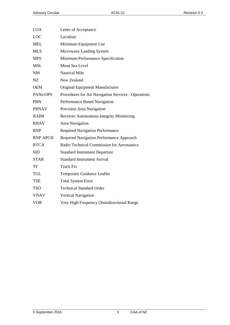
Abbreviations
AC Advisory Circular
ADS-B Automatic Dependent Surveillance - Broadcast
AIP Aeronautical Information Publication
AIRAC Aeronautical Information Regulation and Control
APCH Approach
ARINC Aeronautical Radio, Incorporated
ARP Aerodrome Reference Point
ASE Altimetry System Error
ATS Air Traffic Service
BARO VNAV Barometric Vertical Navigation
CAA Civil Aviation Authority
CAR New Zealand Civil Aviation Rule
CDI Course Deviation Indicator
CFR Code of Federal Regulations
DF Direct Fix
DME Distance Measuring Equipment
Doc Document
EASA European Aviation Safety Agency
FAA Federal Aviation Administration
FD Fault Detection
FDE Fault Detection and Exclusion
FIR Flight Information Region
FMS Flight Management System
Ft Feet
FTE Flight Technical Error
GNSS Global Navigation Satellite system
GPS Global Positioning System
HSI Horizontal Situation Indicator
ICAO International Civil Aviation Organization
IF Initial Fix
IFR Instrument Flight Rules
ILS Instrument Landing System
INU Inertial Navigation Unit
IRU Inertial Reference Unit
JAA Joint Aviation Authority
Advisory Circular AC91-21 Revision 0.3
5 September 2016 3 CAA of NZ
LOA Letter of Acceptance
LOC Localiser
MEL Minimum Equipment List
MLS Microwave Landing System
MPS Minimum Performance Specification
MSL Mean Sea Level
NM Nautical Mile
NZ New Zealand
OEM Original Equipment Manufacturer
PANs-OPS Procedures for Air Navigation Services - Operations
PBN Performance Based Navigation
PRNAV Precision Area Navigation
RAIM Receiver Autonomous Integrity Monitoring
RNAV Area Navigation
RNP Required Navigation Performance
RNP APCH Required Navigation Performance Approach
RTCA Radio Technical Commission for Aeronautics
SID Standard Instrument Departure
STAR Standard Instrument Arrival
TF Track Fix
TGL Temporary Guidance Leaflet
TSE Total System Error
TSO Technical Standard Order
VNAV Vertical Navigation
VOR Very High Frequency Omnidirectional Range

Advisory Circular AC91-21 Revision 0.3
5 September 2016 4 CAA of NZ
Introduction
The purpose of this Advisory Circular (AC) is to provide an acceptable means of compliance with the requirements for RNAV and RNP in order to achieve approval by the Director to conduct these operations. The approval will be specific to an operator and aircraft, with conditions related to the applicable navigation specification(s). This approval process will enable operators to utilise the desired navigation capability in the interests of safety and efficiency.
A reference to “operational approval” in this AC means approval by the Director in writing to conduct flight operations in accordance with any of the following navigation specifications:
i. RNP 1 ii. RNP 2
iii. RNAV 1 iv. RNAV 2 v. RNP APCH
vi. Baro VNAV
The requirements for operational approval are based on rule 91.246 and 91.519 and include aircraft navigation systems and operator procedures. The standards for aircraft equipment and operator procedures are derived from international standards (ICAO) and best practice. Operator procedures must be documented in the Aircraft Flight Manual (AFM), AFM Supplement, Avionics or Aircraft manufacturer’s Pilot Operating Handbook, RNP and/or RNAV manual (as applicable). In the case of the holder of an air operator certificate issued under Part 119, the required information may be documented in the operator’s exposition, provided the operator can demonstrate that the required procedures are complete and appropriately linked. As part of the approval process the Director must also be satisfied that the operator has systems in place to ensure pilots are trained and qualified to conduct the relevant RNAV and RNP operations or instrument procedures.
The process for application is detailed on page 9 of this AC. Airworthiness approval is detailed in Part 2 of this AC and the operator approval process is detailed in Part 3 of this AC.
This AC provides one acceptable means of compliance. If it is not practical for an aircraft operator to get operational approval as specified in this AC, then the operator may apply to the Director to achieve compliance by an alternative means which provides an equivalent level of safety. It is recommended that the operator contact the CAA at their earliest convenience should an alternative means of compliance be contemplated.
The CAA is receptive to any comments on how this AC can be improved in the New Zealand context, and any changes will be highlighted in subsequent versions. The CAA acknowledges the contribution of industry stakeholders in the development of this document.

Advisory Circular AC91-21 Revision 0.3
5 September 2016 5 CAA of NZ
Part 1 General Interim Notice - Transition Clarification
· Terminal Operations:
o Legacy RNAV(GNSS): All aircraft with existing GPS-IFR Terminal approvals may continue to operate on legacy GNSS SID/STAR procedures indefinitely.
o RNAV 1: Except those fitted with equipment listed in interim Table 1, all aircraft with existing GPS-IFR Terminal approvals are approved to conduct RNAV 1 SID/STAR procedures. Owners/Operators of aircraft with equipment listed in interim Table 1 are not authorised to conduct RNAV 1 SID/STAR procedures unless specifically approved to do so by the CAA. Those affected should contact the CAA in the first instance.
o RNP 1: RNP 1 operations require an RNP1 approval. For operations under Part 91 a simplified application form for airworthiness approval is on the CAA website (CAA091-10). Pilots operating under Part 91 who hold a current GNSS rating have RNAV 1, RNAV 2 and RNAV (GNSS) privileges and may exercise RNP 1 privileges as they have met the knowledge and training requirements for pilot approval. After 1 January 2017, pilots wishing to exercise, or continue to exercise, RNP 1 privileges must complete a GNSS rating issue or renewal flight test as outlined in AC61-17 Rev 12.
· Enroute Operations:
o RNAV2: Aircraft with existing GPS-IFR enroute approvals are approved to operate on RNAV2 ATS routes until the next revision of AC91-21 is published.
o RNP2: RNP2 enroute operations must not be published in New Zealand until the next revision of AC91-21 is published.
· CAA is working on PBN implementation as part of New Southern Sky, AC91-21 will be revised as part of New Southern Sky activity.
Interim Table 1: FAA AC 90-100A Non-Compliant Equipment
GPS-IFR Equipment Requiring CAA Approval for RNAV1 SID/STAR Procedures
Manufacturer: Model:
Garmin GPS 155, GPS 165, GPS 300, GPS 155XL
GNC 300XL
Apollo 2001, Apollo 2101, Apollo SL50, Apollo SL60, Apollo SL65, Apollo GX50, Apollo GX55, Apollo GX60, Apollo GX65
Honeywell
(also Bendix King)
CDU-XLS
GNS-500, GNS-1000, GNS-X, GNS-XES, GNS-XL, GNS-XLS
KLN-89B, KLN-90A, KLN-90B, KLN-94, KLN-900
KLS-670
KNS-660

Advisory Circular AC91-21 Revision 0.3
5 September 2016 6 CAA of NZ
The PBN Implementation Plan - New Zealand The PBN implementation plan, available on the CAA website, provides for a number of domestic flight information region RNAV and RNP operations. They comprise standard instrument departures (SIDs), en-route tracks, standard instrument arrivals (STARs), and approaches.
These procedures enable area navigation procedures in surveillance or non-surveillance environments, using GNSS as a primary navigation reference; in certain operations DME/DME/INU may be used as an acceptable navigation reference. The procedures shall be clearly identified in the Aeronautical Information Publication as an RNAV X, RNP X or RNP APCH; the operator shall be responsible for ensuring compliance to these area navigation procedures and seeking approval from the CAA.
New Zealand is moving towards area navigation procedures that have less reliance on ground-based navigation aids. Those operators that adopt area navigation as specified in this AC will benefit from more direct routes, prioritisation and economic operating benefits. The number of area navigation routes will be increasing and the need to maintain the ground based navigation structure as it is today will decrease. Operators that continue to operate referencing ground-based navigation aids will eventually notice less optimal routing and delays as the ground based navigation infrastructure is minimised.
The standards and guidance material used in developing this AC are contained in the following ICAO Documents:
· Annex 10 Volume 1 – Aeronautical telecommunications
· Doc 4444 – Air traffic management
· Doc 7030 – Regional Supplementary Procedures
· Doc 8168 – Aircraft Operations (PANs-OPS)
· Doc 9613 – Performance Based Navigation (PBN), and
· Doc 9849 – Global Navigation Satellite System (GNSS) Manual
The development and operation of area navigation routes and procedures involves design, assessment and approval within the air traffic management system as well as an operational approval.
Operational approval is based upon the following:
Aircraft Capability: the requirements for airworthiness approval are set out in Part 2 of this AC. Operators must demonstrate that the aircraft is eligible for the navigation specification sought, and show that the instruments and equipment comply with one of the airworthiness options.
Operator Procedures: The requirements for operator approval are set out in Part 3 of this AC. These procedures must be documented in a RNP and/or RNAV manual (as applicable), or as part of the operator’s exposition in the case of operations being conducted under Part 119.
Pilot training and qualification: The applicant for operational approval must demonstrate that they have systems in place to ensure that pilots are appropriately trained in accordance with the applicable rule requirements.
The route design approval and operational approval are tightly coupled to provide safety of the operation.
This advisory circular details the requirements for obtaining operational approval to conduct these operations.

Advisory Circular AC91-21 Revision 0.3
5 September 2016 7 CAA of NZ
Regulatory basis Operational approval is based upon the following:
· Aircraft capability: The aircraft must be eligible for the navigation specification sought as demonstrated by the aircraft flight manual or manufacturer instruction. The aircraft instrument and equipment requirements must comply with rule 91.501(2)(ii)(A) and rule 9.519. Part 2 of this AC defines the criteria that the Director will use in assessing for compliance
· Operator Procedures The operator must have procedures in place to ensure crews comply with the requirements of rules 91.409(b), 121.169, 125.165, and 135.165. For RNP operations the documented procedures must include, as a minimum, the information required under rule 91.246(e). The general requirements of rule 91.246(e) also provide a good basis for operator procedures for RNAV. Part 3 of this AC defines he criteria that the director will use in assessing for compliance.
· Pilot training and qualification. Pilot training and qualification requirements for RNAV and RNP are detailed in:
o rule part 61, Subpart Q Instrument ratings;
o rule 91.246(a)(4) Operations in RNP designated airspace;
o rules 119.53 and 19.103 Personnel competency requirements;
o rule part 121 subpart I training, and subpart J Crew Member Competency Requirements;
o rule part 125 subpart I Training, and subpart J Crew Member Competency Requirements; and
o rule part 135 subpart I Training, and subpart J Crew Member Competency Requirements.
The applicant for operational approval must demonstrate that they have systems in place to ensure that pilots are appropriately trained and qualified in accordance with the applicable rule requirements.
PBN Specifications The PBN specifications adopted in the New Zealand FIR are:
For departures (SIDs) and arrivals (STARs)
RNAV 1
RNP 1 (Initially named Basic RNP 1)
Note: The existing RNAV GNSS arrivals and SIDs may be used until 14th November 2013. By this date they must be replaced by RNAV 1 or RNP 1 procedures. The existing GNSS IFR terminal approvals on the CAA Form 2129 and operation specifications are acceptable for the existing RNAV GNSS arrivals and SIDs until 14th November 2013.
For en route operations
RNAV2
Note: Initially these routes will all be available to approved GNSS equipped aircraft, and most routes will be available to DME/DME/IRU equipped aircraft. Operators of the non-GNSS aircraft must ensure that their aircraft only operate on routes applicable to their operational approval.

Advisory Circular AC91-21 Revision 0.3
5 September 2016 8 CAA of NZ
Note: Aircraft with existing GNSS IFR enroute approval may operate RNAV 2 until 14th November 2013, after this date the operator must have applied for and been approved for RNAV 2 operations as defined in this advisory circular.
RNP 2:
Note: By 14th November 2013, RNAV 2 routes that are not available to DME/DME/IRU equipped aircraft will be designated RNP 2 routes.
For approach operations
RNP APCH
Note: Existing RNAV (GNSS) approaches may continue to be flown by operators with existing operational approvals or conditions on CAA Form 2129 and operational specifications which permit their use.
Note: RNP APCH operations requires approval as defined in this advisory circular, no credit will be given for existing RNAV (GNSS) approach approvals.
BARO VNAV
RNAV & RNP Operations in New Zealand Overview RNAV 1 and 2 RNAV operations normally take place in a surveillance environment, the operator is responsible for navigation accuracy and the ATS provider ensures the integrity of the navigation and separation through monitoring. RNAV operations may be conducted using either GNSS or DME/DME/IRU equipment. Where ATS surveillance is not available, ATS will provide procedural separation and pilots must exercise vigilance to ensure navigation remains within tolerance.
RNAV 1 operations: take place in terminal areas and require that the aircraft remains within 0.5 nm of the track (FTE). This will require a display in front of the pilot (within ±15º of the pilots primary field of view) confirming that the aircraft is within the required track tolerance.
For DME/DME/IRU applications the CDI full scale deflection must be set at ±1 nm for the entire procedure; the aircraft must remain within ½ scale deflection of the CDI
For GNSS applications within 30NM of the Aerodrome Reference Point (ARP), CDI scaling in certificated GNSS equipment has a full scale deflection of ±1NM, so the aircraft must remain within ½ scale deflection of the CDI. The RAIM integrity limit is set at 1nm.
GNSS outside 30NM of the ARP:
In the case of receivers certificated to TSO C145/146, the CDI scaling defaults to ±2NM, whereas receivers certificated to TSO C129, the CDI scaling defaults to ±5NM. In cases where the system cannot be set to RNAV 1, the CDI scales must be set to ±1NM full scale deflection. Alternate compliance may be shown by use of navigational display maps with digital readout, refer to specific requirements set out in Part 2 of this advisory circular.
RNAV 2 operations take place in the en-route environment and require that the aircraft can remain within 1NM of track. This also requires a display in front of the pilot (within ±15º of the pilots primary field of view) confirming that the aircraft is within the required track tolerance.
For DME/DME/IRU applications the CDI full scale deflection must be set at ±2 nm for the entire procedure; the aircraft must remain within ½ scale deflection of the CDI

Advisory Circular AC91-21 Revision 0.3
5 September 2016 9 CAA of NZ
For GNSS receivers certificated to TSO 145/146 the CDI is set to ±2NM and the aircraft must remain within ½ scale deflection of the CDI.
For GNSS receivers certificated to TSO C129, the CDI scaling is set at ±5NM. This scaling is acceptable for RNAV 2 operations, the aircraft must remain within ±1NM of the desired track i.e. remain within 1/5th of the full scale deflection.
RNP 1 and 2 RNP operations may take place outside areas of surveillance and the aircraft operator is responsible for ensuring the integrity of the navigation solution. This requires on board performance monitoring and alerting as well as monitoring of flight technical error. Most IFR-approved GNSS receivers with RAIM meet the on board performance monitoring and alerting requirement.
To ensure obstacle clearance and traffic separation it is essential that pilots conducting RNP operations keep their aircraft within the track tolerances appropriate to the route or procedure.
RNP 1 operations take place in terminal areas and require that the aircraft remains within 0.5NM of the track (FTE). This will require a display in front of the pilot (within ±15º of the pilots primary field of view) confirming that the aircraft is within the required track tolerance.
Within 30NM of the aerodrome reference point (ARP), CDI scaling in certificated GNSS equipment has a full scale deflection of ±1NM, so the aircraft must remain within ½ scale deflection of the CDI. The RAIM integrity limit is set at 1NM.
Outside 30NM of the ARP:
In the case of receivers certificated to TSO C145/146, the CDI scaling defaults to ±2NM, whereas receivers certificated to TSO C129, the CDI scaling defaults to ±5NM. In cases where the system cannot be set to RNP 1, the CDI scales must be set to ±1NM full scale deflection. Alternate compliance may be shown by use of navigational display maps with digital readout, refer to specific requirements set out in Part 2 of this advisory circular.
Beyond 30NM of the ARP the RAIM integrity limit changes from 1NM to 2NM. The pilot and system must be capable of setting the RAIM integrity alert to 1NM when 30NM beyond the ARP.
RNP 2 operations take place in the en-route environment and require that the aircraft can remain within 1NM of track. This also requires a display in front of the pilot (within ±15º of the pilots primary field of view) confirming that the aircraft is within the required track tolerance.
In the case of receivers certificated to TSO 145/146 the CDI is set to ±2NM and the aircraft must remain within ½ scale deflection of the CDI.
In the case of receivers certificated to TSO C129, the CDI scaling is set at ±5NM. The CDI scales must be set to ±2NM full scale deflection. Alternate compliance may be shown by use of navigational display maps with digital readout, refer to specific requirements set out in Part 2 of this advisory circular
Human Factors There are a number of human factors issues associated with the transition to PBN that can present hazards. Care must be taken in the installation of the equipment, the design and charting of the procedures, the use of navigation databases, and the operational practices developed to minimise the risks.
Refer to specific aircraft system requirements in Part 2 of this advisory circular for the operation being conducted.
Advisory Circular AC91-21 Revision 0.3
5 September 2016 10 CAA of NZ
Refer to specific operational requirements in Part 3 of this advisory circular for the operation being conducted.
Published procedures should be at least as easy to interpret and follow as a standard VOR/DME approach plate. They should be presented in a standard format in compliance with ICAO Doc 8168.
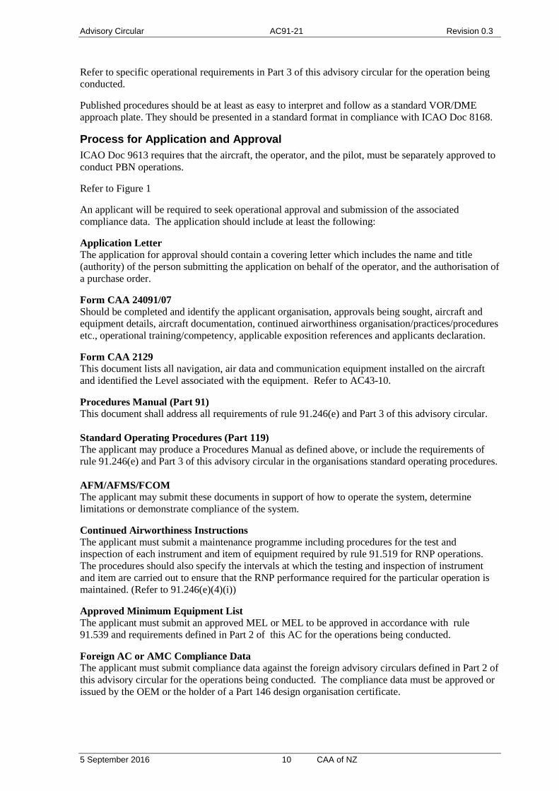
Process for Application and Approval ICAO Doc 9613 requires that the aircraft, the operator, and the pilot, must be separately approved to conduct PBN operations.
Refer to Figure 1
An applicant will be required to seek operational approval and submission of the associated compliance data. The application should include at least the following:
Application Letter The application for approval should contain a covering letter which includes the name and title (authority) of the person submitting the application on behalf of the operator, and the authorisation of a purchase order.
Form CAA 24091/07 Should be completed and identify the applicant organisation, approvals being sought, aircraft and equipment details, aircraft documentation, continued airworthiness organisation/practices/procedures etc., operational training/competency, applicable exposition references and applicants declaration.
Form CAA 2129 This document lists all navigation, air data and communication equipment installed on the aircraft and identified the Level associated with the equipment. Refer to AC43-10.
Procedures Manual (Part 91) This document shall address all requirements of rule 91.246(e) and Part 3 of this advisory circular. Standard Operating Procedures (Part 119) The applicant may produce a Procedures Manual as defined above, or include the requirements of rule 91.246(e) and Part 3 of this advisory circular in the organisations standard operating procedures. AFM/AFMS/FCOM The applicant may submit these documents in support of how to operate the system, determine limitations or demonstrate compliance of the system.
Continued Airworthiness Instructions The applicant must submit a maintenance programme including procedures for the test and inspection of each instrument and item of equipment required by rule 91.519 for RNP operations. The procedures should also specify the intervals at which the testing and inspection of instrument and item are carried out to ensure that the RNP performance required for the particular operation is maintained. (Refer to 91.246(e)(4)(i))
Approved Minimum Equipment List The applicant must submit an approved MEL or MEL to be approved in accordance with rule 91.539 and requirements defined in Part 2 of this AC for the operations being conducted.
Foreign AC or AMC Compliance Data The applicant must submit compliance data against the foreign advisory circulars defined in Part 2 of this advisory circular for the operations being conducted. The compliance data must be approved or issued by the OEM or the holder of a Part 146 design organisation certificate.

Advisory Circular AC91-21 Revision 0.3
5 September 2016 11 CAA of NZ
NZ AC Compliance Data The applicant must submit compliance data against the New Zealand requirements defined in Part 2 of this advisory circular for the operations being conducted. The compliance data must be approved or issued by the OEM or the holder of a Part 146 design organisation certificate.
Electrical Loads Analysis The applicant must submit an electrical loads analysis as defined in the “Aircraft Airworthiness Compliance” section of each operation defined in Part 2 of this advisory circular. The compliance data must be issued by the OEM, STC holder or the holder of a Part 146 design organisation certificate.
If the aircraft electrical loads have not changed since delivery of the aircraft from the OEM, and the original configuration includes equipment required by this advisory circular, and the OEM states compliance to the relevant advisory circulars defined in Part 2, the applicant will not be required to submit an electrical loads analysis.
System Safety Analysis The applicant must submit a System Safety Analysis as defined in the “Aircraft Airworthiness Compliance” section of each operation defined in Part 2 of this AC, demonstrating compliance of the “Aircraft Navigation System Integrity”. The compliance data must be issued by the OEM, STC holder or the holder of a Part 146 design organisation certificate.
If the aircraft navigation systems have not changed since delivery of the aircraft from the OEM, and the original configuration includes equipment required by this AC, and the OEM states compliance to the relevant ACs defined in Part 2, the applicant will not be required to submit a system safety analysis.
Note: Each pilot must be approved for RNAV or RNP Operations. In the case of Part 91 operations the pilot will have been assessed in accordance with AC61-17 and their logbook endorsed with the specific operation. Pilots within a Part 119 organisation must be trained and authorised by that organisation in accordance with their exposition for the aircraft and type operation (i.e. navigation specification).
Upon receipt of the application and associated compliance documentation the CAA will review the data pack content and advise the applicant of any missing data. Once all data is with the CAA a review will be carried out by flight operational and aircraft certification staff. Any non-conformance will be identified to the applicant; it may be necessary for the applicant to go back to the OEM or Part 146 design organisation. If considered necessary, the CAA may require a flight evaluation to confirm function and performance requirements are satisfied.
Where an applicant is successful the following will be issued by the CAA:
CAA Form 2129 issued with conditions i.e. RNAV1 RNP1, RNP APCH
Operational Specifications: In the case of Part 119 operators, stating the approval levels.
Letter of Operational Approval: In the case of Part 91 operators, stating the approval levels.
Standard Operating Procedure Acceptance Letter: In the case of Part 119 operators.
Procedures Manual Acceptance Letter: In the case of Part 91 operators.
Advisory Circular AC91-21 Revision 0.3
5 September 2016 12 CAA of NZ
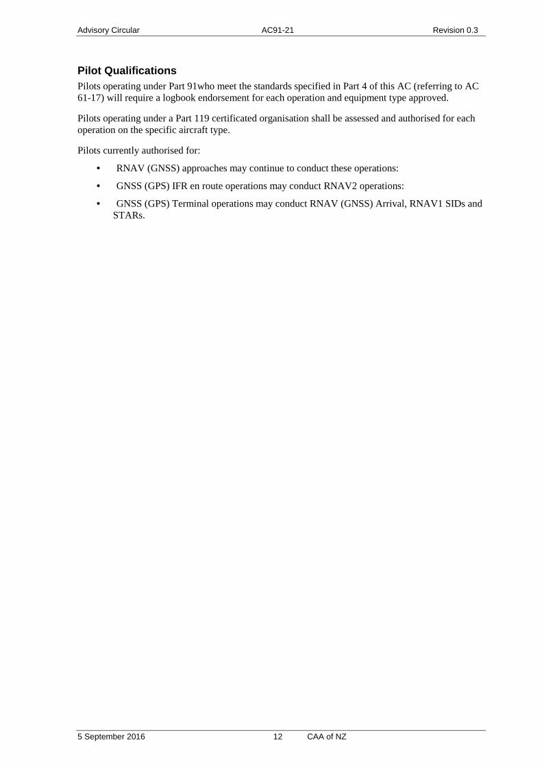
Pilot Qualifications Pilots operating under Part 91who meet the standards specified in Part 4 of this AC (referring to AC 61-17) will require a logbook endorsement for each operation and equipment type approved.
Pilots operating under a Part 119 certificated organisation shall be assessed and authorised for each operation on the specific aircraft type.
Pilots currently authorised for:
· RNAV (GNSS) approaches may continue to conduct these operations:
· GNSS (GPS) IFR en route operations may conduct RNAV2 operations:
· GNSS (GPS) Terminal operations may conduct RNAV (GNSS) Arrival, RNAV1 SIDs and STARs.

Advisory Circular AC91-21 Revision 0.3
5 September 2016 13 CAA of NZ
Figure 1: Operational Approval Application Process Applicant Request
Letter to CAA
CompletedForm CAA 24091/07
CompletedForm CAA 2129
Procedures Manual/Standard Operating
Procedures
AFM or AFMS or FCOM
Foreign AC or AMC Compliance Data
NZ AC Compliance Data
Electrical Loads Analysis Safety Analysis
Approved Minimum Equipment List
Continued Airworthiness Instructions
Applicant Data Pack Submission
Airworthiness Compliance Data to be issued by OEM or an approved Design Organisation
CAA Application Review Additional Application Data Request
Part 91 Pilot
Logbook Entry
CAA Compliance Review
Aircraft Certification Unit
Form CAA2129RNAV & RNP Conditions
Air Transport Flight Operation Unit
Operational Specifications
Authorised
Standard Operating ProceduresAccepted
General Aviation Group
RNAV – RNP Operational Letter
of Approval
Procedures Manual Acceptance
Personnel & Flight Training Unit
RNAV – RNP Operational Letter
of Approval
Procedures Manual Acceptance
Part 61Pilot Licenses & Ratings
NZ AC 61-17(RNAV & RNP)
Additional Compliance Data Request
All Operators Part 119 Operators Part 91 General Aviation Operators Part 91/141 Flying School/Training Operators
Aircraft Compliant

Advisory Circular AC91-21 Revision 0.3
5 September 2016 14 CAA of NZ
Part 2 Aircraft Airworthiness Approval
This AC provides guidance on airworthiness compliance of the following operations:
· Part 2.1: RNAV 1 or 2
· Part 2.2: RNP 2
· Part 2.3: RNP 1
· Part 2.4: RNP APCH and BARO VNAV
New Zealand has adopted the ICAO guidance defined in Performance Based Manual Document 9613 edition 4.
Compliance demonstration takes reference to EASA AMC’s or FAA AC’s as well as specific requirements defined in the tables of the sections referenced above. Where possible it is the intent of the CAA to review and accept existing approvals.
The introduction of the RNAV and RNP operations above affects the GPS IFR approvals issued to date; aircraft systems will need to be reviewed to demonstrate compliance. The approvals above are specific to the route/procedure classification; they do not affect existing equipment approvals for routes not defined as RNAV 1 or 2, RNP 1, RNP 2 or RNPS APCH (BARO VNAV).
In the case of RNAV 2, existing GPS IFR en-route approvals will be valid on RNAV 2 routes until 14th November 2013; operators are encouraged to apply for RNAV 2 approvals well in advance of this date to allow a reasonable period for CAA assessment and to avoid a period of ineligibility to use GNSS en route navigation.
Existing GPS IFR terminal approvals will be valid on existing GNSS Arrivals and SIDs until the 14th November 2013, after that date these procedures will be reclassified as RNAV 1 or RNP 1. Operators are encouraged to apply for RNAV 1 or RNP 1 approvals well in advance of this date to allow a reasonable period for CAA assessment and to avoid a period of ineligibility to use GNSS en route navigation.
Aircraft eligibility must be determined through demonstration of compliance against the relevant requirements and criteria set out in this AC. Airworthiness aspects of compliance must be demonstrated by the OEM, approved data acceptable to the Director, or approved Part 146 design organization. Credit may be taken for compliance statements in OEM approved documents or holder of approved installation documentation. Limitations of installation/systems must be clearly defined in aircraft flight manuals or aircraft flight manual supplements.
Use of GNSS
This section provides an overview of the GNSS requirements with respect to RNAV and RNP operations. The requirements are driven by aircraft navigation system integrity and navigation continuity, these are defined in the relevant aircraft airworthiness tables of the operation being conducted and are summarised below:
· Aircraft navigation system integrity failure classification: Major (1e-5)
· Navigation continuity classification:
o Minor (1e-3), if an alternative means of navigation is available to proceed to a suitable airport.
Advisory Circular AC91-21 Revision 0.3
5 September 2016 15 CAA of NZ
o Major (1e-5), if no alternate navigation means exist.
Note: determining that the aircraft system satisfies the major classification will require an assessment of aircraft systems including: power source reliability and protection, GNSS receiver reliability, GNSS antenna reliability, display reliability etc. This assessment should be conducted following the guidance of FAA AC 23.1309 or AC25.1309 and their referenced documents.
Note: GNSS receivers with approved fault detection exclusion (FDE) functionality provide capability to exclude satellite vehicle integrity failures and continue to provide a navigation solution. Those GNSS receivers without FDE (most TSO-C129()1 receivers) will not provide a navigation solution upon a single satellite vehicle integrity failure; the aircraft systems will need to be assessed for particular risk analysis relating to satellite vehicle integrity failures.
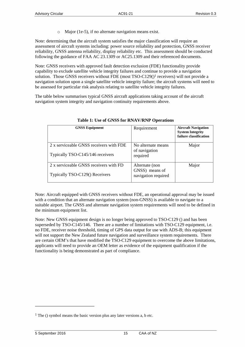
The table below summarises typical GNSS aircraft applications taking account of the aircraft navigation system integrity and navigation continuity requirements above.
Table 1: Use of GNSS for RNAV/RNP Operations GNSS Equipment Requirement Aircraft Navigation
System Integrity failure classification
2 x serviceable GNSS receivers with FDE
Typically TSO-C145/146 receivers
No alternate means of navigation required
Major
2 x serviceable GNSS receivers with FD
Typically TSO-C129() Receivers
Alternate (non GNSS) means of navigation required
Major
Note: Aircraft equipped with GNSS receivers without FDE, an operational approval may be issued with a condition that an alternate navigation system (non-GNSS) is available to navigate to a suitable airport. The GNSS and alternate navigation system requirements will need to be defined in the minimum equipment list.
Note: New GNSS equipment design is no longer being approved to TSO-C129 () and has been superseded by TSO-C145/146. There are a number of limitations with TSO-C129 equipment, i.e. no FDE, receiver noise threshold, timing of GPS data output for use with ADS-B; this equipment will not support the New Zealand future navigation and surveillance system requirements. There are certain OEM’s that have modified the TSO-C129 equipment to overcome the above limitations, applicants will need to provide an OEM letter as evidence of the equipment qualification if the functionality is being demonstrated as part of compliance.
1 The () symbol means the basic version plus any later versions a, b etc.

Advisory Circular AC91-21 Revision 0.3
5 September 2016 16 CAA of NZ
Part 2.1 RNAV 1 and 2 Airworthiness Compliance
The Director may approve RNAV 1 and 2 in accordance with the guidance and navigation specifications in ICAO Document 9613 (4th edition). The USA issued FAA AC 90-100, followed on by AC 90-100A for RNAV 1 and 2; Europe (JAA) issued TGL 10 for RNAV 1 and 2. There are differences between the USA and European guidance. ICAO document 9613 defines an international standard for RNAV 1 and 2 and accounts for the differences between the USA and European guidance material. A New Zealand Civil Aviation Authority RNAV 1 and 2 approval will satisfy the airworthiness requirements of ICAO (adopted NZ standard), as well as meeting the USA and European requirements.
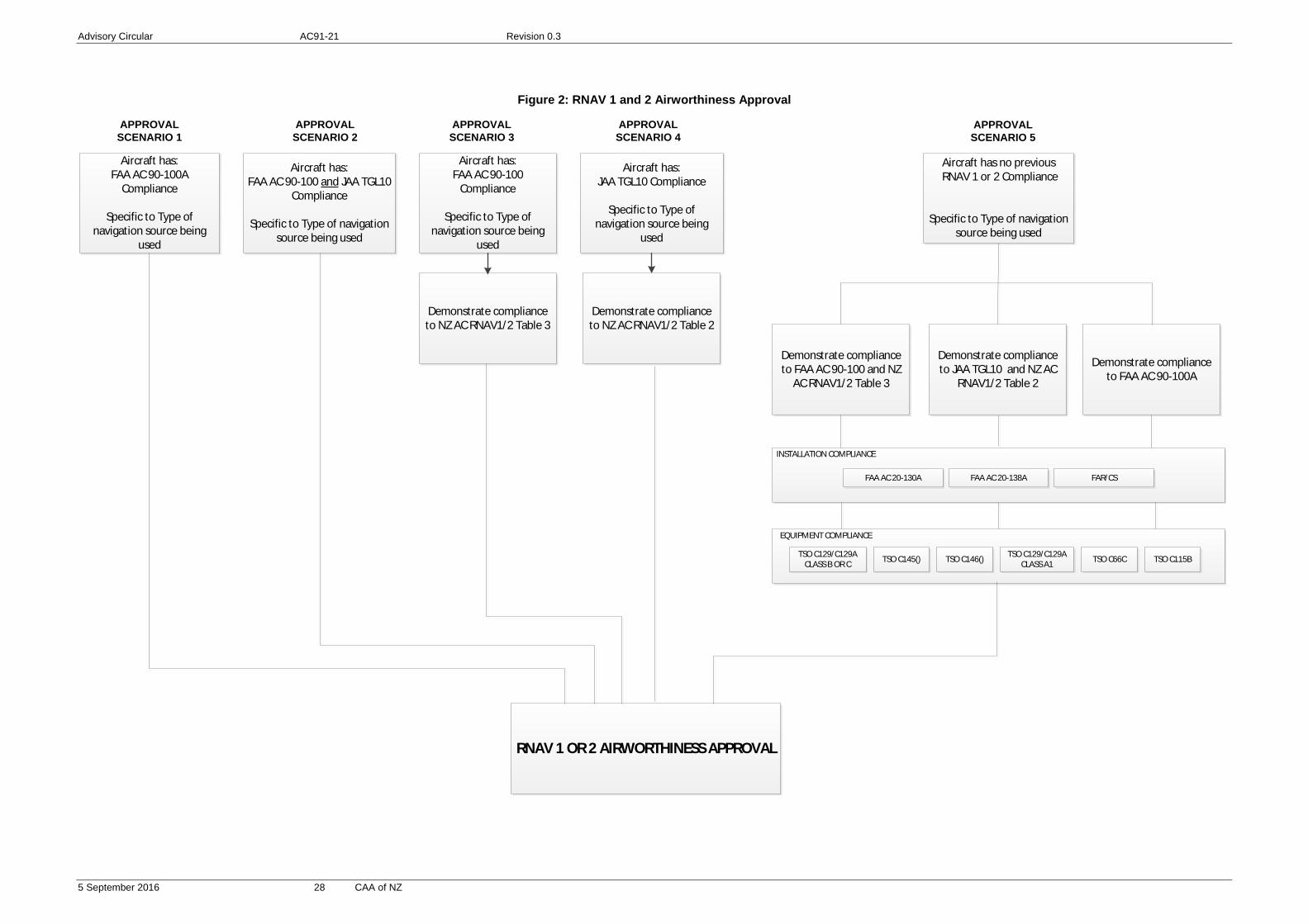
An overview of compliance demonstration is detailed in Figure 2.
Credit can be taken for compliance to USA and/or European guidance, it may be necessary to demonstrate additional compliance to specific NZ requirements.
Table 2 provides information about the operation as well as defining specific airworthiness requirements. Table 3 through Table 7 define additional airworthiness requirements depending on the specific navigation structure being used to demonstrate compliance.
The applicant is required to demonstrate compliance to the rows in Table 2 that are identified with “airworthiness requirement” as well as other tables referenced within Table 2 for the particular navigation source or operation.
Table 2: AIRWORTHINESS ASPECTS OF RNAV 1 and RNAV 2
Specification/Requirement Definition/Compliance
Purpose RNAV 1 and 2 may be used enroute and in terminal area navigation. Terminal navigation includes SIDS, STARS and approach procedures up to the FAF
Surveillance Environment RNAV 1 and 2 are expected to be conducted in a surveillance environment; operation outside surveillance or below Minimum Vectoring Altitude requires a state safety case.
Communications Environment (airworthiness requirement)
RNAV1 and 2 are conducted in direct controller-pilot communication. All aircraft must have dual communication systems to ensure continued pilot-controller communications.
Applicable Specification:
ICAO PBN Doc 9613 Volume II, Part B Chapter 3
Procedure Accuracy (TSE): (airworthiness requirement)
RNAV 1 Lateral/Along track total system error must be within +/-1nm for at least 95% of the total flight time. RNAV 2 Lateral/Along track total system error must be within +/-2nm for at least 95% of the total flight time.
Navigation infrastructure supporting the navigation specification (airworthiness requirement)
· GNSS · DME/DME* · DME/DME/INU**
*Note: due to DME coverage in NZ, DME/DME operations will be limited.
**Note: IRU position error expected to be less than 2nm per 15

Advisory Circular AC91-21 Revision 0.3
5 September 2016 17 CAA of NZ
Table 2: AIRWORTHINESS ASPECTS OF RNAV 1 and RNAV 2
Specification/Requirement Definition/Compliance
minutes FMS Note: Operators dependent on INU during DME outages must
ensure the FMS does not use VOR/DME before reverting to INU coasting.
RAIM Note: Operators dependent on GNSS must ensure RAIM availability during flight planning
Aircraft with existing RNAV 1/2 approvals that provide complete airworthiness compliance (airworthiness requirement) Note: compliance is being sought for the specific navigation structure being used and referenced in the operational approval
Refer to Figure 2 Aircraft compliant to PRNAV (TGL 10) AND USA RNAV FAA AC 90-100 satisfy the requirements of NZ RNAV1/2
OR Aircraft compliant to FAA AC 90-100A
Aircraft with existing RNAV 1/2 approvals that provide partial airworthiness compliance (airworthiness requirement) Note: compliance is being sought for the specific navigation structure being used and referenced in the operational approval
Refer to Figure 2 Aircraft compliant to PRNAV (TGL 10) OR USA RNAV FAA AC 90-100 For TGL10 approvals, additional compliance demonstration to Table 3 is required. For FAA AC 90-100 approvals, additional compliance demonstration to Table 4 is required
Aircraft with no previous RNAV 1/2 airworthiness compliance (airworthiness requirement) Note: compliance is being sought to the specific navigation structure being used and referenced in the operational approval
Refer to Figure 2 Compliance to be provided by the OEM or holder of the installation approval for :
· TGL No.10 and Table 3 OR
· FAA AC 90-100 and Table 4 OR
· FAA AC 90-100A
Aircraft Airworthiness Compliance (airworthiness requirement)
Compliance demonstration is dependent on existing compliance to RNAV 1 and 2, the specific RNAV 1 or 2 operation being conducted and aircraft configuration. Figure 2 provides an overview of the various approaches to airworthiness compliance. In addition to FAA AC’s or EASA AMC’s there may be need to demonstrate compliance to NZ requirements outlined in this appendix tables and outlined in the preceding three rows. Note: A key aspect of compliance is system safety, the classification of
aircraft navigation system failure is Major, and compliance will need to be demonstrated by a system safety analysis in accordance with FAA AC xx.1309 methodologies. If the aircraft navigation systems have not changed since delivery of the aircraft from the OEM, and the original configuration includes equipment required by this advisory circular, and the OEM states compliance to the relevant advisory circulars defined in Part 2, the applicant will not be required to submit a system safety analysis.
Note: An electrical loads analysis is required to demonstrate that the aircraft battery system is capable of supporting 30minutes or 60

Advisory Circular AC91-21 Revision 0.3
5 September 2016 18 CAA of NZ
Table 2: AIRWORTHINESS ASPECTS OF RNAV 1 and RNAV 2
Specification/Requirement Definition/Compliance
minute operation upon primary power generation failure. Duration is dependent on applicable certification rule and operation. If the aircraft electrical loads have not changed since delivery of the aircraft from the OEM, and the original configuration includes equipment required by this advisory circular, and the OEM states compliance to the relevant advisory circulars defined in Part 2, the applicant will not be required to submit an electrical loads analysis.
Note: System/equipment requirements are dependent on the specific performance and functionalities listed herein, as well as the operational RNAV Continuity requirement below.
Acceptable GNSS Types and Installation Requirements (airworthiness requirement)
· TSO C129/C129A sensor (Class B or C) and requirements of TSO-C115b FMS, installed for IFR in accordance with FAA AC 20-130A
· TSO C145()and requirements of TSO-C115b FMS, installed for IFR in accordance with FAA AC 20-130A or AC 20-138A.
· *TSO-C129/C129A Class A1 installed for IFR in accordance with FAA AC 20-138 or AC 20-138A
· *TSO-C146() installed for IFR in accordance with FAA AC20-138A
*Note: These systems must not deviate from the functionality described in Table 5.
Acceptable DME/DME Types (airworthiness requirement)
· TSO-C66c DME · Compliance to be shown against requirements of Table 6
Acceptable DME/DME/IRU Configuration (airworthiness requirement)
· Same requirements as acceptable DME/DME types, Table 6
AND · Compliance is shown against requirements of Table 7
Aircraft Navigation System Integrity
Malfunction of an aircraft system is classified as a Major condition (1x10⁻⁵ per hour)
RNAV Continuity (operational requirement that may affect system and airworthiness requirements)
For RNAV operations the loss of function is minor if the operator can revert to a different navigation system and proceed to a suitable airport. If no alternate means exist then the loss of functions considered Major.
Minimum Equipment List (airworthiness requirement)
RNAV 1 and 2 provisions must be included in the MEL approved by the CAA.
Continuing Airworthiness (airworthiness requirement)
The operator must submit continuing airworthiness instructions for the aircraft configuration, including a reliability program for monitoring equipment. A means to verify and accept subsequent changes or service bulletins to the aircraft does not invalidate the operational approval.

Advisory Circular AC91-21 Revision 0.3
5 September 2016 19 CAA of NZ
Table 3 : RNAV 1 or 2 APPROVAL FROM A TGL 10 APPROVAL
Aircraft has TGL10 approval
Need to confirm these performance capabilities
for NZ RNAV 1 and RNAV 2 Note
If approval includes use of DME/VOR (DME/VOR may be used as the only positioning input where this is explicitly allowed.)
RNAV 1 does not accommodate any routes based on DME/VOR RNAV
RNAV system performance must be based on GNSS, DME/DME, or DME/DME/IRU. However, DME/VOR input does not have to be inhibited or deselected
If approval includes use of DME/DME
No action required if RNAV system performance meets specific navigation criteria in Table 6 (DME/DME only) or Table 7 (DME/DME/IRU)
Operator can ask manufacturer or check FAA website for list of compliant systems (see the Note below at foot of this table)
RNAV SID specific requirement with DME/DME aircraft
RNAV guidance available no later than 500ft above field elevation (AFE) on AC 90-100 Type B procedure
Operator should add these operational procedures
If approval includes use of GNSS
No action required
Note— http://www.faa.gov/about/office_org/headquarters_offices/avs/offices/afs/afs400/afs410/policy_guidance/
Table 4 : RNAV 1 or 2 APPROVAL FROM FAA AC 90-100 APPROVAL
Aircraft has FAA AC 90-100 Approval
Need to confirm these performance capabilities
for NZ RNAV 1 and RNAV 2 Note
If approval is based on GNSS (TSO-C129)
GPS pseudo-range step detector and GPS health word checking is required in accordance with TSO C129a/ETSO C129a
The operator should check if pseudo-range step detector and health word checking is supported by the installed GPS receiver or check if GPS receiver is approved in accordance with TSO C129a/ETSO C129a
No navigation database updating process required under AC 90-100
Data suppliers and avionics data suppliers must have Letter of Acceptance (LOA) in accordance with Table 5 m)
The operator should ask the data supplier for the status of the RNAV equipment
Advisory Circular AC91-21 Revision 0.3
5 September 2016 20 CAA of NZ
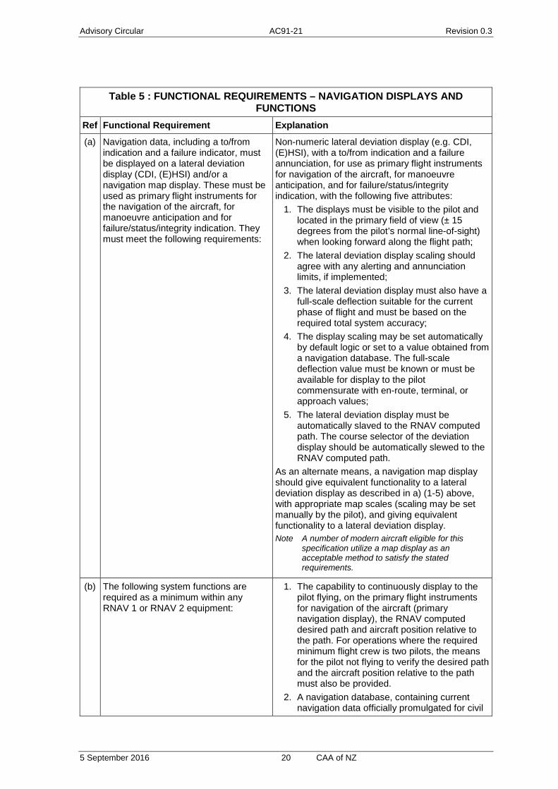
Table 5 : FUNCTIONAL REQUIREMENTS – NAVIGATION DISPLAYS AND FUNCTIONS
Ref Functional Requirement Explanation
(a) Navigation data, including a to/from indication and a failure indicator, must be displayed on a lateral deviation display (CDI, (E)HSI) and/or a navigation map display. These must be used as primary flight instruments for the navigation of the aircraft, for manoeuvre anticipation and for failure/status/integrity indication. They must meet the following requirements:
Non-numeric lateral deviation display (e.g. CDI, (E)HSI), with a to/from indication and a failure annunciation, for use as primary flight instruments for navigation of the aircraft, for manoeuvre anticipation, and for failure/status/integrity indication, with the following five attributes:
1. The displays must be visible to the pilot and located in the primary field of view (± 15 degrees from the pilot’s normal line-of-sight) when looking forward along the flight path;
2. The lateral deviation display scaling should agree with any alerting and annunciation limits, if implemented;
3. The lateral deviation display must also have a full-scale deflection suitable for the current phase of flight and must be based on the required total system accuracy;
4. The display scaling may be set automatically by default logic or set to a value obtained from a navigation database. The full-scale deflection value must be known or must be available for display to the pilot commensurate with en-route, terminal, or approach values;
5. The lateral deviation display must be automatically slaved to the RNAV computed path. The course selector of the deviation display should be automatically slewed to the RNAV computed path.
As an alternate means, a navigation map display should give equivalent functionality to a lateral deviation display as described in a) (1-5) above, with appropriate map scales (scaling may be set manually by the pilot), and giving equivalent functionality to a lateral deviation display. Note A number of modern aircraft eligible for this
specification utilize a map display as an acceptable method to satisfy the stated requirements.
(b) The following system functions are required as a minimum within any RNAV 1 or RNAV 2 equipment:
1. The capability to continuously display to the pilot flying, on the primary flight instruments for navigation of the aircraft (primary navigation display), the RNAV computed desired path and aircraft position relative to the path. For operations where the required minimum flight crew is two pilots, the means for the pilot not flying to verify the desired path and the aircraft position relative to the path must also be provided.
2. A navigation database, containing current navigation data officially promulgated for civil

Advisory Circular AC91-21 Revision 0.3
5 September 2016 21 CAA of NZ
Table 5 : FUNCTIONAL REQUIREMENTS – NAVIGATION DISPLAYS AND FUNCTIONS
Ref Functional Requirement Explanation
aviation, which can be updated in accordance with the aeronautical information regulation and control (AIRAC) cycle and from which ATS routes can be retrieved and loaded into the RNAV system. The stored resolution of the data must be sufficient to achieve negligible path definition error. The database must be protected against pilot modification of the stored data.
3. The means to display the validity period of the navigation data to the pilot.
4. The means to retrieve and display data stored in the navigation database relating to individual waypoints and navigation aids, to enable the pilot to verify the route to be flown.
5. The capacity to load from the database into the RNAV system the entire RNAV segment of the SID or STAR to be flown.
Note Due to variability in RNAV systems, this document defines the RNAV segment from the first occurrence of a named waypoint, track, or course to the last occurrence of a named waypoint, track, or course. Heading legs prior to the first named waypoint or after the last named waypoint do not have to be loaded from the database.
(c) The means to display the following items, either in the pilot’s primary field of view, or on a readily accessible display page:
1. the active navigation sensor type; 2. the identification of the active (To) waypoint; 3. the ground speed or time to the active (To)
waypoint; and 4. the distance and bearing to the active (To)
waypoint.
(d) The capability to execute a “direct to” function.
(e) The capability for automatic leg sequencing with the display of sequencing to the pilot.
(f) The capability to execute ATS routes extracted from the on-board database, including the capability to execute flyover and fly-by turns.
(g) The aircraft must have the capability to automatically execute leg transitions and maintain tracks consistent with the following ARINC 424 path terminators, or their equivalent. — initial fix (IF) — course to fix (CF) — direct to fix (DF)
Note 1 Path terminators are defined in ARINC Specification 424, and their application is described in more detail in RTCA documents DO-236B and DO-201A, and EUROCAE ED-75B and ED-77.
Note 2 Numeric values for courses and tracks must be automatically loaded from the RNAV system database.

Advisory Circular AC91-21 Revision 0.3
5 September 2016 22 CAA of NZ
Table 5 : FUNCTIONAL REQUIREMENTS – NAVIGATION DISPLAYS AND FUNCTIONS
Ref Functional Requirement Explanation
— track to fix (TF)
(h) The aircraft must have the capability to automatically execute leg transitions consistent with VA, VM and VI ARINC 424 path terminators, or must be able to be manually flown on a heading to intercept a course or to go direct to another fix after reaching a procedure-specified altitude.
(i) The aircraft must have the capability to automatically execute leg transitions consistent with CA and FM ARINC 424 path terminators, or the RNAV system must permit the pilot to readily designate a waypoint and select a desired course to or from a designated waypoint.
(j) The capability to load an RNAV ATS route from the database, by route name, into the RNAV system is a recommended function. However, if all or part of the RNAV route (not SID or STAR) is entered through the manual entry of waypoints from the navigation database, the paths between a manually entered waypoint and the preceding and following waypoints must be flown in the same manner as a TF leg in terminal airspace.
(k) The capability to display an indication of the RNAV system failure, including the associated sensors, in the pilot’s primary field of view.
(l) For multi-sensor systems, the capability for automatic reversion to an alternate RNAV sensor if the primary RNAV sensor fails. This does not preclude providing a means for manual navigation source selection.
(m) Database integrity The navigation database suppliers should comply with RTCA DO-200A/EUROCAE document ED 76, Standards for Processing Aeronautical Data. A Letter of Acceptance (LOA), issued by the appropriate regulatory authority to each of the participants in the data chain demonstrates compliance with this requirement. Discrepancies that invalidate a route must be reported to the navigation database supplier and affected routes must be prohibited by an operator’s notice to its flight crew. Aircraft operators should consider the need to conduct periodic checks of the operational

Advisory Circular AC91-21 Revision 0.3
5 September 2016 23 CAA of NZ
Table 5 : FUNCTIONAL REQUIREMENTS – NAVIGATION DISPLAYS AND FUNCTIONS
Ref Functional Requirement Explanation
navigation databases in order to meet existing quality system requirements.
Table 6 : CRITERIA FOR DME/DME RNAV SYSTEM
Ref Functional Requirement Explanation
(a) Accuracy is based on the performance standards of TSO-C66c.
(b) Tuning and updating position of DME facilities
The DME/DME RNAV system must: 1. position update within 30 seconds of tuning
DME navigation facilities; 2. auto-tune multiple DME facilities; and 3. provide continuous DME/DME position
updating. A third DME facility or a second pair has been available for at least the previous 30 seconds, there must be no interruption in DME/DME positioning when the RNAV system switches between DME stations/pairs.
(c) Using facilities in the State AIPs DME/DME RNAV systems must only use DME facilities identified in State AIPs. The systems must not use facilities indicated by the State as inappropriate for RNAV 1 and/or RNAV 2 operations in the AIP or facilities associated with an ILS or MLS that uses a range offset. This may be accomplished by:
1. excluding specific DME facilities, which are known to have a deleterious effect on the navigation solution, from the aircraft’s navigation database, when the RNAV routes are within reception range of these DME facilities.
2. using an RNAV system that performs reasonableness checks to detect errors from all received DME facilities and excludes these facilities from the navigation position solution, when appropriate (e.g. preclude tuning co-channel DME facilities when the DME facilities signals-in-space overlap). (See the guidance on testing of reasonableness checks beginning in section l) of this table.
(d) DME facility relative angles When needed to generate a DME/DME position, the RNAV system must use, as a minimum, DMEs with a relative include angle between 30° and 150°.
(e) RNAV system use of DMEs The RNAV system may use any valid receivable DME facility (listed in the AIP) regardless of its
Advisory Circular AC91-21 Revision 0.3
5 September 2016 24 CAA of NZ
Table 6 : CRITERIA FOR DME/DME RNAV SYSTEM
Ref Functional Requirement Explanation
location. A valid DME facility: 1. broadcasts an accurate facility identifier signal; 2. satisfies the minimum field strength
requirements; and 3. is protected from other interfering DME signals
according to the co-channel and adjacent channel requirements.
When needed to generate a DME/DME position, as a minimum, the RNAV system must use an available and valid terminal (low altitude) and/or en-route (high altitude) DME anywhere within the following region around the DME facility:
1. greater than or equal to 3 NM from the facility; and
2. less than 40 degrees above the horizon when viewed from the DME facility and out to 160 NM.
Note The use of a figure-of-merit in approximating the designated operational coverage (DOC) of a particular facility is accepted, provided precautions are taken to ensure that the figure-of-merit is coded so that the aircraft will use the facility everywhere within the DOC. The use of DMEs associated with ILS or MLS is not required.
(f) No requirement to use VOR, NDB, LOC, IRU or AHRS
There is no requirement to use VOR (VHF omnidirectional radio range), LOC (localizer), NDB (non-directional radio beacon), IRU (inertial reference unit) or AHRS (attitude and heading reference system) during normal operation of the DME/DME RNAV system.
(g) Position estimation error When using a minimum of two DME facilities meeting the criteria in section e) of this table, and any other DME facilities not meeting that criteria, the 95 per cent position estimation error must be better than or equal to the following equation:
2 2 2 21, 1, 2, 2,
/( ) ( )
2 2sin( )
s + s + s + ss £
aair sis air sis
DME DME
Where: ssis = 0.05 NM sair is MAX {0.085 NM, (0.125 per cent of
distance)} µ inclusion angle (30° to 150°) Note This performance requirement is met for any
navigation system that uses two DME stations simultaneously, limits the DME inclusion angle to between 30° and 150° and uses DME sensors that meet the accuracy requirements of TSO-C66c. If the RNAV system uses DME facilities outside of

Advisory Circular AC91-21 Revision 0.3
5 September 2016 25 CAA of NZ
Table 6 : CRITERIA FOR DME/DME RNAV SYSTEM
Ref Functional Requirement Explanation
their published designated operational coverage, the DME signal-in-space error of valid facilities can still be assumed to be sground=0.05NM.
(h) Preventing erroneous guidance from other facilities
The RNAV system must ensure that the use of facilities outside their service volume (where the minimum field strength, co-channel and adjacent-channel interference requirements may not be satisfied) do not cause erroneous guidance. This could be accomplished by including reasonableness checking when initially tuning a DME facility or excluding a DME facility when there is a co-channel DME within line-of-sight.
(i) Preventing erroneous VOR signals-in-space
VOR may be used by the RNAV system, however, the RNAV system must ensure an erroneous VOR signal-in-space does not affect the position error when in DME/DME coverage. For example, this may be accomplished by weighting and/or monitoring the VOR signal with DME/DME to ensure it does not mislead position results (e.g. through reasonableness checks in section l) of this table).
(j) Ensuring RNAV systems use operational facilities
The RNAV system must use operational DME facilities. DME facilities listed by NOTAM as unavailable (e.g. under test or other maintenance) could still reply to an airborne interrogation, therefore, non-operational facilities must not be used. An RNAV system may exclude non-operational facilities by checking the identification or inhibiting the use of facilities identified as not operational.
(k) Operational mitigations Operational mitigations such as pilot monitoring of the RNAV system’s navigation updating source(s), or time-intensive programming/de-selection of multiple DME stations, should be performed before any workload-intensive or critical phase of flight. Note De-selecting single facilities listed by NOTAM
as out-of-service and/or programming route-defined “critical” DME is acceptable when this mitigation requires no pilot action during a critical phase of flight. A programming requirement also does not imply the pilot should complete manual entry of DME facilities which are not in the navigation database.
(l) Reasonableness checks Many RNAV systems perform a reasonableness check to verify valid DME measurements. Reasonableness checks are very effective against database errors or erroneous system acquisition (such as co-channel facilities), and typically fall into two classes:
1. those the RNAV system uses after it acquires a new DME, where it compares the aircraft’s position before using the DME to the aircraft’s

Advisory Circular AC91-21 Revision 0.3
5 September 2016 26 CAA of NZ
Table 6 : CRITERIA FOR DME/DME RNAV SYSTEM
Ref Functional Requirement Explanation
range to the DME; and 2. those the RNAV system continuously uses,
based on redundant information (e.g. extra DME signals or IRU data).
General requirements. The reasonableness checks are intended to prevent navigation aids from being used for navigation update in areas where the data can lead to radio position fix errors due to co-channel interference, multipath, and direct signal screening. In lieu of using the published service volume of the radio navigation aid, the navigation system should provide checks which preclude the use of duplicate frequency navaids within range, over-the-horizon navaids, and use of navaids with poor geometry. Assumptions. Under the following conditions, reasonableness checks can be invalid:
1. A DME signal does not remain valid just because it was valid when acquired.
2. Extra DME signals may not be available. The intent of this specification is to support operations where the infrastructure is minimal (e.g. when only two DMEs are available for parts of the route).
Use of stressing conditions to test effectiveness. When a reasonableness check is used to satisfy any requirement in these criteria, the effectiveness of the check must be tested under stressful conditions. An example of this condition is a DME signal that is valid at acquisition and ramps off during the test (similar to what a facility undergoing testing might do), when there is only one other supporting DME or two signals of equal strength.
Table 7 : CRITERIA FOR DME/DME AND INERTIAL REFERNCE RNAV SYSTEM Ref Functional Requirement Explanation
(a) Inertial system performance must satisfy the criteria of US 14 CFR Part 121, Appendix G.
(b) Automatic position updating capability from the DME/DME solution is required.
Note Operators/pilots should contact manufacturers to discern if any annunciation of inertial coasting is suppressed following loss of radio updating.
(c) Since some aircraft systems revert to VOR/DME-based navigation before reverting to inertial coasting, the impact of VOR radial accuracy, when the VOR is greater than 40 NM from the aircraft, must not affect aircraft position accuracy.
One means of accomplishing this objective is for RNAV systems to exclude VORs greater than 40 NM from the aircraft.

Advisory Circular AC91-21 Revision 0.3
5 September 2016 27 CAA of NZ
Advisory Circular AC91-21 Revision 0.3
5 September 2016 28 CAA of NZ
Figure 2: RNAV 1 and 2 Airworthiness Approval
APPROVAL SCENARIO 1
APPROVAL SCENARIO 2
APPROVAL SCENARIO 3
Aircraft has:FAA AC 90-100A
Compliance
Specific to Type of navigation source being
used
Aircraft has:FAA AC 90-100 and JAA TGL10
Compliance
Specific to Type of navigation source being used
Aircraft has:FAA AC 90-100
Compliance
Specific to Type of navigation source being
used
Aircraft has:JAA TGL10 Compliance
Specific to Type of navigation source being
used
Aircraft has no previous RNAV 1 or 2 Compliance
Specific to Type of navigation source being used
APPROVAL SCENARIO 4
APPROVAL SCENARIO 5
RNAV 1 OR 2 AIRWORTHINESS APPROVAL
Demonstrate compliance to NZ AC RNAV1/2 Table 3
Demonstrate compliance to NZ AC RNAV1/2 Table 2
Demonstrate compliance to FAA AC 90-100 and NZ
AC RNAV1/2 Table 3
Demonstrate compliance to JAA TGL10 and NZ AC
RNAV1/2 Table 2
Demonstrate compliance to FAA AC 90-100A
INSTALLATION COMPLIANCE
FAA AC 20-130A FAA AC 20-138A FAR/CS
TSO C129/C129ACLASS B OR C TSO C145() TSO C146() TSO C129/C129A
CLASS A1
EQUIPMENT COMPLIANCE
TSO C66C TSO C115B

Advisory Circular AC91-21 Revision 0.3
5 September 2016 29 CAA of NZ
Part 2.2 RNP 2 Airworthiness Compliance
RNP 2 may be approved by the Director in accordance with the guidance and navigation specifications in ICAO Document 9613 (4th edition). RNP 2 is a recent addition to the ICAO navigation manual. The ICAO manual and existing FAA ACs (AC 20-130A, AC 20-138A, AC20-138B, as applicable) provide guidance on the airworthiness requirements for RNP 2 and will be used to inform he CAA operational approval decision. The airworthiness requirements specified in table 8 and table 9 of this AC also apply
An overview of compliance demonstration is detailed in Figure 3.
The applicant is required to demonstrate compliance to the rows in Table 8 that are identified with “airworthiness requirement” as well as other tables referenced within Table 8 for the particular operation.
Table 8: AIRWORTHINESS ASPECTS OF RNP 2
Specification/Requirement Definition/Compliance
Purpose RNP 2 is used for enroute applications. This AC does not address fixed radius transitions OR remote and oceanic operations using RNP2.
Surveillance Environment RNP2 is expected to be conducted in a limited or no surveillance environment
Communications Environment (airworthiness requirement)
RNP2 requires communications commensurate with operational considerations such as route spacing, traffic density, complexity and contingency procedures. All aircraft must have dual communication systems to ensure continued pilot-controller communications.
Applicable Specification:
ICAO PBN Doc 9613 Volume II, Part C Chapter 2
Procedure Accuracy (TSE): (airworthiness requirement)
RNP 2 Lateral/Along track system error must be within +/-2nm for at least 95% of the total flight time. Note pilots of an aircraft with RNP input selection capability should
select a navigation accuracy of 2nm.
Flight Technical Error (airworthiness requirement)
Flight technical error shall not exceed 1nm. This must be demonstrated by the pilot being able to operate the aircraft within the FTE utilizing displays, autopilot or flight guidance. Note The use of a deviation indicator with 2 NM full-scale deflection
has been found to be an acceptable means of compliance. The use of an autopilot or flight director has been found to be an acceptable means of compliance; this means of compliance requires monitoring of FTE.
Note The lateral deviation scaling should be 2nm, for some TSO-C129a equipment it will be necessary to adjust the scaling from +/-5nm to +/-2nm
Note Some aircraft do not display or compute path during turns, brief deviations of FTE (e.g. overshoots or undershoots) during and immediately after turns up to 2nm are permitted. FTE of 1nm must be satisfied during intercepts following turns and on straight segments.
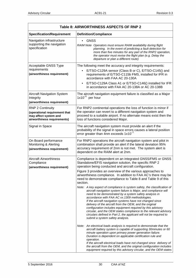
Advisory Circular AC91-21 Revision 0.3
5 September 2016 30 CAA of NZ
Table 8: AIRWORTHINESS ASPECTS OF RNP 2
Specification/Requirement Definition/Compliance
Navigation infrastructure supporting the navigation specification
· GNSS RAIM Note Operators must ensure RAIM availability during flight
planning. In the event of predicting a fault detection for more than five minutes for any part of the RNP2 operation, the operator must revise the flight plan (e.g. Delay the departure or plan a different route)
Acceptable GNSS Type requirements (airworthiness requirement)
The following meet the accuracy and integrity requirements: · E/TSO-C129A sensor (Class B or C), E/TSO-C145() and
requirements of E/TSO-C115b FMS, installed for IFR in accordance with FAA AC 20-130A
· E/TSO-C129A Class A1 or E/TSO-C146() installed for IFR in accordance with FAA AC 20-138A or AC 20-138B
Aircraft Navigation System Integrity (airworthiness requirement)
The aircraft navigation equipment failure is classified as a Major 1x10⁻⁵ per hour
RNP 2 Continuity (operational requirement that may affect system and airworthiness requirements)
For RNP2 continental operations the loss of function is minor if the operator can revert to a different navigation system and proceed to a suitable airport. If no alternate means exist then the loss of functions considered Major.
Signal in Space The aircraft navigation system must provide an alert if the probability of the signal in space errors causes a lateral position error greater than 4nm exceeds 1x10⁻⁷.
On Board performance Monitoring & Alerting (airworthiness requirement)
For RNP2 operations the aircraft navigation system and pilot in combination shall provide an alert if the lateral deviation 95% accuracy requirement of 2nm is not met. The system alert is dependent on the RAIM alert at 2nm.
Aircraft Airworthiness Compliance (airworthiness requirement)
Compliance is dependent on an integrated GNSS/FMS or GNSS Standalone/EFIS navigation solution, the specific RNP 2 operation being conducted and aircraft configuration. Figure 3 provides an overview of the various approaches to airworthiness compliance. In addition to FAA AC’s there may be need to demonstrate compliance to Table 8 and Table 9 of this section. Note: A key aspect of compliance is system safety, the classification of
aircraft navigation system failure is Major, and compliance will need to be demonstrated by a system safety analysis in accordance with FAA AC xx.1309 methodologies. If the aircraft navigation systems have not changed since delivery of the aircraft from the OEM, and the original configuration includes equipment required by this advisory circular, and the OEM states compliance to the relevant advisory circulars defined in Part 2, the applicant will not be required to submit a system safety analysis.
Note: An electrical loads analysis is required to demonstrate that the aircraft battery system is capable of supporting 30minutes or 60 minute operation upon primary power generation failure. Duration is dependent on applicable certification rule and operation. If the aircraft electrical loads have not changed since delivery of the aircraft from the OEM, and the original configuration includes equipment required by this advisory circular, and the OEM states
Advisory Circular AC91-21 Revision 0.3
5 September 2016 31 CAA of NZ
Table 8: AIRWORTHINESS ASPECTS OF RNP 2
Specification/Requirement Definition/Compliance
compliance to the relevant advisory circulars defined in Part 2, the applicant will not be required to submit an electrical loads analysis.
Note System/equipment requirements are dependent on the specific performance and functionalities listed herein, as well as the operational RNP2 Continuity requirement above. The operational continuity requirement may require dual GNSS receivers with FDE.
Minimum Equipment List (airworthiness requirement)
RNP2 provisions must be included in the MEL approved by the CAA.
Continuing Airworthiness (airworthiness requirement)
The operator must submit continuing airworthiness instructions for the aircraft configuration, including a reliability program for monitoring equipment. A means to verify and accept subsequent changes or service bulletins to the aircraft does not invalidate the operational approval.
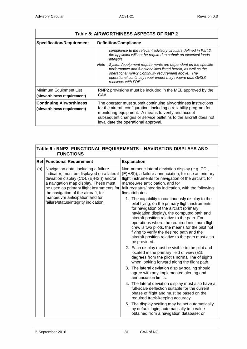
Table 9 : RNP2 FUNCTIONAL REQUIREMENTS – NAVIGATION DISPLAYS AND FUNCTIONS
Ref Functional Requirement Explanation
(a) Navigation data, including a failure indicator, must be displayed on a lateral deviation display (CDI, (E)HSI)) and/or a navigation map display. These must be used as primary flight instruments for the navigation of the aircraft, for manoeuvre anticipation and for failure/status/integrity indication.
Non-numeric lateral deviation display (e.g. CDI, (E)HSI)), a failure annunciation, for use as primary flight instruments for navigation of the aircraft, for manoeuvre anticipation, and for failure/status/integrity indication, with the following five attributes:
1. The capability to continuously display to the pilot flying, on the primary flight instruments for navigation of the aircraft (primary navigation display), the computed path and aircraft position relative to the path. For operations where the required minimum flight crew is two pilots, the means for the pilot not flying to verify the desired path and the aircraft position relative to the path must also be provided.
2. Each display must be visible to the pilot and located in the primary field of view (±15 degrees from the pilot’s normal line of sight) when looking forward along the flight path.
3. The lateral deviation display scaling should agree with any implemented alerting and annunciation limits.
4. The lateral deviation display must also have a full-scale deflection suitable for the current phase of flight and must be based on the required track-keeping accuracy
5. The display scaling may be set automatically by default logic; automatically to a value obtained from a navigation database; or

Advisory Circular AC91-21 Revision 0.3
5 September 2016 32 CAA of NZ
Table 9 : RNP2 FUNCTIONAL REQUIREMENTS – NAVIGATION DISPLAYS AND FUNCTIONS
Ref Functional Requirement Explanation
manually by flight crew procedures. The full-scale deflection value must be known or must be available for display to the pilot commensurate with the required track keeping accuracy.
6. The lateral deviation display must be automatically slaved to the computed path. The course selector of the deviation display should be automatically slewed to the computed path or the pilot must adjust the CDI or HSI selected course to the computed desired track.
As an alternate means of compliance, a navigation map display can provide equivalent functionality to a lateral deviation display as described in 1-6 above, with appropriate map scales and giving equivalent functionality to a lateral deviation display. The map scale should be set manually to a value appropriate for the RNP 2 operation.
(b) The RNP 2 operation requires the following minimum system and equipment functions:
1. A navigation database, containing current navigation data officially promulgated for civil aviation, which can be updated in accordance with the aeronautical information regulation and control (AIRAC) cycle and from which RNP 2 routes can be retrieved and loaded into the RNP system. The stored resolution of the data must be sufficient to achieve negligible PDE. Database protections must prevent pilot modification of the on-board, stored data.
2. A means to display the validity period of the navigation data to the pilot.
3. A means to retrieve and display data stored in the navigation database relating to individual waypoints and NAVAIDs (when applicable), to enable the pilot to verify the RNP 2 route to be flown.
4. For RNP 2 tracks in oceanic/remote continental airspace using flexible (e.g. organized) tracks, a means to enter the unique waypoints required to build a track assigned by the ATS provider.
(c) The means to display the following items, either in the pilot’s primary field of view, or on a readily accessible display:
1. the active navigation sensor type; 2. the identification of the active (To) waypoint; 3. the groundspeed or time to the active (To)
waypoint; and 4. the distance and bearing to the active (To)
waypoint.
(d) The capability to execute a “direct to” function.
The aircraft and avionics manufacturers should identify any limitations associated with conducting the “direct to” function during RNP 2 operations in
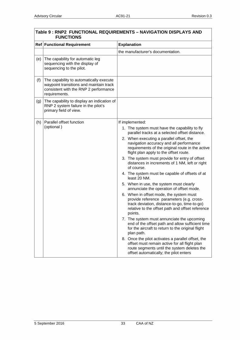
Advisory Circular AC91-21 Revision 0.3
5 September 2016 33 CAA of NZ
Table 9 : RNP2 FUNCTIONAL REQUIREMENTS – NAVIGATION DISPLAYS AND FUNCTIONS
Ref Functional Requirement Explanation
the manufacturer’s documentation.
(e) The capability for automatic leg sequencing with the display of sequencing to the pilot.
(f) The capability to automatically execute waypoint transitions and maintain track consistent with the RNP 2 performance requirements.
(g) The capability to display an indication of RNP 2 system failure in the pilot’s primary field of view.
(h) Parallel offset function (optional )
If implemented: 1. The system must have the capability to fly
parallel tracks at a selected offset distance. 2. When executing a parallel offset, the
navigation accuracy and all performance requirements of the original route in the active flight plan apply to the offset route.
3. The system must provide for entry of offset distances in increments of 1 NM, left or right of course.
4. The system must be capable of offsets of at least 20 NM.
5. When in use, the system must clearly annunciate the operation of offset mode.
6. When in offset mode, the system must provide reference parameters (e.g. cross-track deviation, distance-to-go, time-to-go) relative to the offset path and offset reference points.
7. The system must annunciate the upcoming end of the offset path and allow sufficient time for the aircraft to return to the original flight plan path.
8. Once the pilot activates a parallel offset, the offset must remain active for all flight plan route segments until the system deletes the offset automatically; the pilot enters
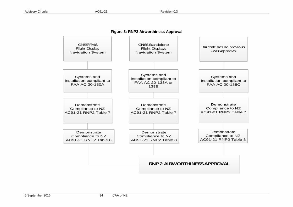
Advisory Circular AC91-21 Revision 0.3
5 September 2016 34 CAA of NZ
Figure 3: RNP2 Airworthiness Approval
Systems and installation compliant to
FAA AC 20-130A
Demonstrate Compliance to NZ
AC91-21 RNP2 Table 8
RNP 2 AIRWORTHINESS APPROVAL
Demonstrate Compliance to NZ
AC91-21 RNP2 Table 7
GNSS/FMSFlight Display
Navigation System
GNSS StandaloneFlight Displays
Navigation System
Systems and installation compliant to
FAA AC 20-138A or 138B
Demonstrate Compliance to NZ
AC91-21 RNP2 Table 8
Demonstrate Compliance to NZ
AC91-21 RNP2 Table 7
Aircraft has no previous GNSS approval
Systems and installation compliant to
FAA AC 20-138C
Demonstrate Compliance to NZ
AC91-21 RNP2 Table 8
Demonstrate Compliance to NZ
AC91-21 RNP2 Table 7

Advisory Circular AC91-21 Revision 0.3
5 September 2016 35 CAA of NZ
Part 2.3 RNP 1 Airworthiness Compliance
New Zealand will approve RNP 1 in accordance with the guidance and navigation specifications in ICAO Document 9613 (4th edition).
Compliance is based upon existing FAA advisory circulars and the specific airworthiness requirements in Table 10 and all requirements in Table 11 of this appendix.
The applicant is required to demonstrate compliance to the rows in Table 10 that are identified with “airworthiness requirement” as well as other tables referenced within Table 10 for the particular operation.
An overview compliance demonstration is detailed in Figure 4.
Note RNP 1 was originally published as Basic RNP 1; approvals under the original nomenclature remain valid.
Table 10: AIRWORTHINESS ASPECTS OF RNP 1
Specification/Requirement Definition/Compliance
Purpose RNP 1 is used for terminal applications. The procedures are referred to as SIDS and STARS, but are also intended to be applicable to initial and intermediate approach segments. This advisory circular does not address radius to fix legs.
Surveillance Environment RNP1 is expected to be conducted in a limited or no surveillance environment
Communications Environment (airworthiness requirement)
RNP1 requires comms commensurate with operational considerations such as route spacing, traffic density, complexity and contingency procedures. All aircraft must have dual communication systems to ensure continued pilot-controller communications.
Applicable Specification:
ICAO PBN Doc 9613 Volume II, Part C Chapter 3
Procedure Accuracy (TSE): (airworthiness requirement)
RNP 1 Lateral/along track total system error must be within +/-1nm for at least 95% of the total flight time. Note pilots of an aircraft with RNP input selection capability should
select a navigation accuracy of 1nm.
Flight Technical Error (airworthiness requirement)
Flight technical error shall not exceed 0.5nm. This must be demonstrated by the pilot being able to operate the aircraft within the FTE utilizing displays, autopilot or flight guidance. Note The use of a deviation indicator with 1 NM full-scale deflection
has been found to be an acceptable means of compliance. The use of an autopilot or flight director has been found to be an acceptable means of compliance; this means of compliance requires monitoring of FTE.
Note GNSS default to a lateral deviation scale greater than 1nm when beyond 30nm the Airport Reference Point (ARP). For RNP1 operations beyond 30nm from the ARP the lateral deviation scale will need to be set at 1nm. The pilot must be competent in changing scales.
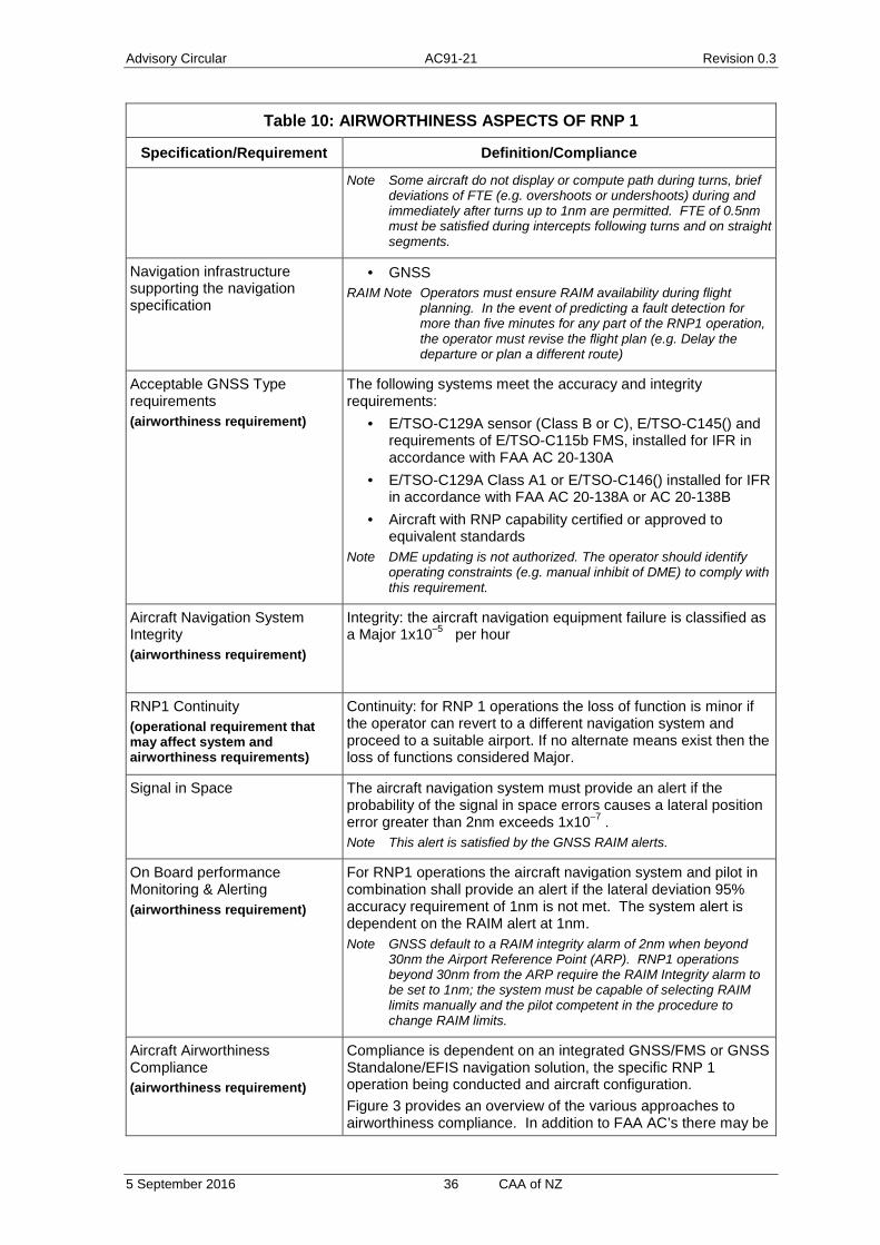
Advisory Circular AC91-21 Revision 0.3
5 September 2016 36 CAA of NZ
Table 10: AIRWORTHINESS ASPECTS OF RNP 1
Specification/Requirement Definition/Compliance
Note Some aircraft do not display or compute path during turns, brief deviations of FTE (e.g. overshoots or undershoots) during and immediately after turns up to 1nm are permitted. FTE of 0.5nm must be satisfied during intercepts following turns and on straight segments.
Navigation infrastructure supporting the navigation specification
· GNSS RAIM Note Operators must ensure RAIM availability during flight
planning. In the event of predicting a fault detection for more than five minutes for any part of the RNP1 operation, the operator must revise the flight plan (e.g. Delay the departure or plan a different route)
Acceptable GNSS Type requirements (airworthiness requirement)
The following systems meet the accuracy and integrity requirements:
· E/TSO-C129A sensor (Class B or C), E/TSO-C145() and requirements of E/TSO-C115b FMS, installed for IFR in accordance with FAA AC 20-130A
· E/TSO-C129A Class A1 or E/TSO-C146() installed for IFR in accordance with FAA AC 20-138A or AC 20-138B
· Aircraft with RNP capability certified or approved to equivalent standards
Note DME updating is not authorized. The operator should identify operating constraints (e.g. manual inhibit of DME) to comply with this requirement.
Aircraft Navigation System Integrity (airworthiness requirement)
Integrity: the aircraft navigation equipment failure is classified as a Major 1x10⁻⁵ per hour
RNP1 Continuity (operational requirement that may affect system and airworthiness requirements)
Continuity: for RNP 1 operations the loss of function is minor if the operator can revert to a different navigation system and proceed to a suitable airport. If no alternate means exist then the loss of functions considered Major.
Signal in Space The aircraft navigation system must provide an alert if the probability of the signal in space errors causes a lateral position error greater than 2nm exceeds 1x10⁻⁷ . Note This alert is satisfied by the GNSS RAIM alerts.
On Board performance Monitoring & Alerting (airworthiness requirement)
For RNP1 operations the aircraft navigation system and pilot in combination shall provide an alert if the lateral deviation 95% accuracy requirement of 1nm is not met. The system alert is dependent on the RAIM alert at 1nm. Note GNSS default to a RAIM integrity alarm of 2nm when beyond
30nm the Airport Reference Point (ARP). RNP1 operations beyond 30nm from the ARP require the RAIM Integrity alarm to be set to 1nm; the system must be capable of selecting RAIM limits manually and the pilot competent in the procedure to change RAIM limits.
Aircraft Airworthiness Compliance (airworthiness requirement)
Compliance is dependent on an integrated GNSS/FMS or GNSS Standalone/EFIS navigation solution, the specific RNP 1 operation being conducted and aircraft configuration. Figure 3 provides an overview of the various approaches to airworthiness compliance. In addition to FAA AC’s there may be

Advisory Circular AC91-21 Revision 0.3
5 September 2016 37 CAA of NZ
Table 10: AIRWORTHINESS ASPECTS OF RNP 1
Specification/Requirement Definition/Compliance
need to demonstrate compliance to Table 10 and Table 11 of this section. Note: A key aspect of compliance is system safety, the classification of
aircraft navigation system failure is Major, and compliance will need to be demonstrated by a system safety analysis in accordance with FAA AC xx.1309 methodologies. If the aircraft navigation systems have not changed since delivery of the aircraft from the OEM, and the original configuration includes equipment required by this advisory circular, and the OEM states compliance to the relevant advisory circulars defined in Part 2, the applicant will not be required to submit a system safety analysis.
Note: An electrical loads analysis is required to demonstrate that the aircraft battery system is capable of supporting 30minutes or 60 minute operation upon primary power generation failure. Duration is dependent on applicable certification rule and operation. If the aircraft electrical loads have not changed since delivery of the aircraft from the OEM, and the original configuration includes equipment required by this advisory circular, and the OEM states compliance to the relevant advisory circulars defined in Part 2, the applicant will not be required to submit an electrical loads analysis.
Note System/equipment requirements are dependent on the specific
performance and functionalities listed herein, as well as the operational RNP1 Continuity requirement above. The continuity requirement may require dual GNSS receivers with FDE.
Minimum Equipment List (airworthiness requirement)
RNP1 provisions must be included in the MEL approved by the CAA.
Continuing Airworthiness (airworthiness requirement)
The operator must submit continuing airworthiness instructions for the aircraft configuration, including a reliability program for monitoring equipment. A means to verify and accept subsequent changes or service bulletins to the aircraft does not invalidate the operational approval.
Table 11 : RNP 1 FUNCTIONAL REQUIREMENTS – NAVIGATION DISPLAYS AND FUNCTIONS
Ref Functional Requirement Explanation
(a) Navigation data, including a failure indicator, must be displayed on a lateral deviation display (CDI, (E)HSI)) and/or a navigation map display. These must be used as primary flight instruments for the navigation of the aircraft, for manoeuvre anticipation and for failure/status/integrity indication.
Non-numeric lateral deviation display (e.g. CDI, (E)HSI)), a failure annunciation, for use as primary flight instruments for navigation of the aircraft, for manoeuvre anticipation, and for failure/status/integrity indication, with the following attributes:
1. The capability to continuously display to the pilot flying, on the primary flight instruments for navigation of the aircraft
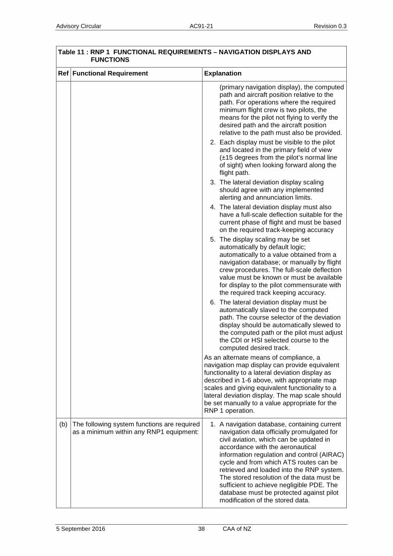
Advisory Circular AC91-21 Revision 0.3
5 September 2016 38 CAA of NZ
Table 11 : RNP 1 FUNCTIONAL REQUIREMENTS – NAVIGATION DISPLAYS AND FUNCTIONS
Ref Functional Requirement Explanation
(primary navigation display), the computed path and aircraft position relative to the path. For operations where the required minimum flight crew is two pilots, the means for the pilot not flying to verify the desired path and the aircraft position relative to the path must also be provided.
2. Each display must be visible to the pilot and located in the primary field of view (±15 degrees from the pilot’s normal line of sight) when looking forward along the flight path.
3. The lateral deviation display scaling should agree with any implemented alerting and annunciation limits.
4. The lateral deviation display must also have a full-scale deflection suitable for the current phase of flight and must be based on the required track-keeping accuracy
5. The display scaling may be set automatically by default logic; automatically to a value obtained from a navigation database; or manually by flight crew procedures. The full-scale deflection value must be known or must be available for display to the pilot commensurate with the required track keeping accuracy.
6. The lateral deviation display must be automatically slaved to the computed path. The course selector of the deviation display should be automatically slewed to the computed path or the pilot must adjust the CDI or HSI selected course to the computed desired track.
As an alternate means of compliance, a navigation map display can provide equivalent functionality to a lateral deviation display as described in 1-6 above, with appropriate map scales and giving equivalent functionality to a lateral deviation display. The map scale should be set manually to a value appropriate for the RNP 1 operation.
(b) The following system functions are required as a minimum within any RNP1 equipment:
1. A navigation database, containing current navigation data officially promulgated for civil aviation, which can be updated in accordance with the aeronautical information regulation and control (AIRAC) cycle and from which ATS routes can be retrieved and loaded into the RNP system. The stored resolution of the data must be sufficient to achieve negligible PDE. The database must be protected against pilot modification of the stored data.
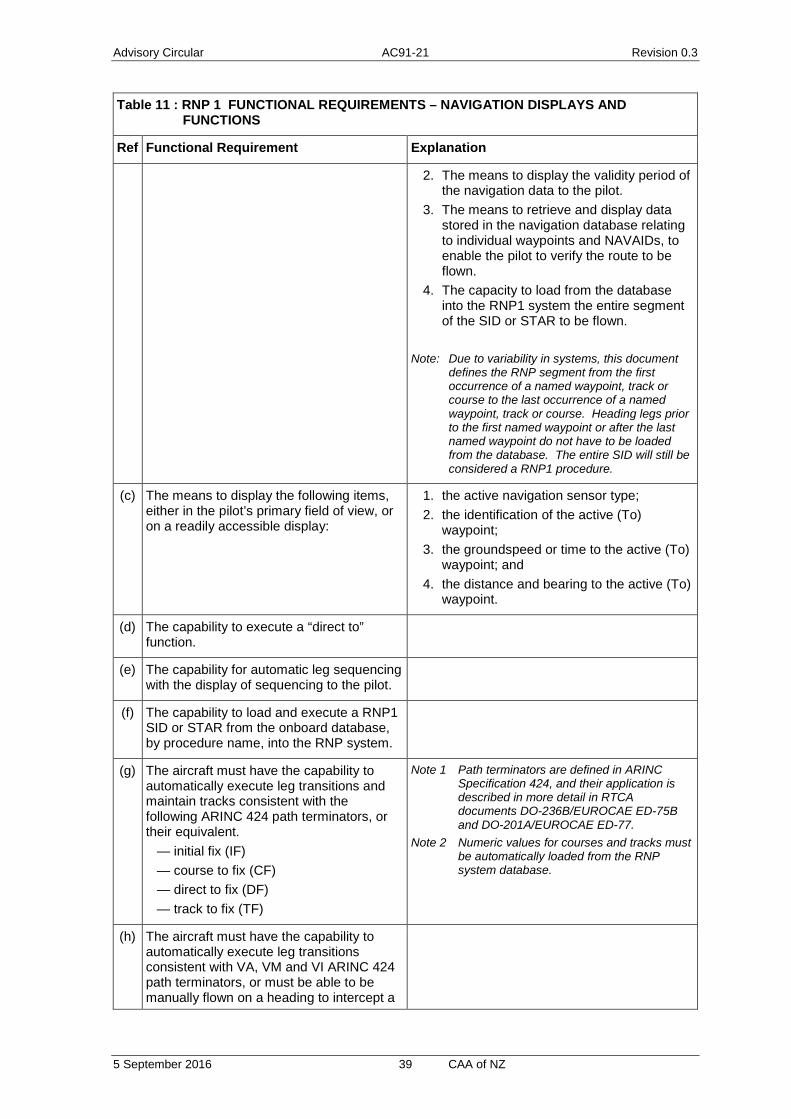
Advisory Circular AC91-21 Revision 0.3
5 September 2016 39 CAA of NZ
Table 11 : RNP 1 FUNCTIONAL REQUIREMENTS – NAVIGATION DISPLAYS AND FUNCTIONS
Ref Functional Requirement Explanation
2. The means to display the validity period of the navigation data to the pilot.
3. The means to retrieve and display data stored in the navigation database relating to individual waypoints and NAVAIDs, to enable the pilot to verify the route to be flown.
4. The capacity to load from the database into the RNP1 system the entire segment of the SID or STAR to be flown.
Note: Due to variability in systems, this document
defines the RNP segment from the first occurrence of a named waypoint, track or course to the last occurrence of a named waypoint, track or course. Heading legs prior to the first named waypoint or after the last named waypoint do not have to be loaded from the database. The entire SID will still be considered a RNP1 procedure.
(c) The means to display the following items, either in the pilot’s primary field of view, or on a readily accessible display:
1. the active navigation sensor type; 2. the identification of the active (To)
waypoint; 3. the groundspeed or time to the active (To)
waypoint; and 4. the distance and bearing to the active (To)
waypoint.
(d) The capability to execute a “direct to” function.
(e) The capability for automatic leg sequencing with the display of sequencing to the pilot.
(f) The capability to load and execute a RNP1 SID or STAR from the onboard database, by procedure name, into the RNP system.
(g) The aircraft must have the capability to automatically execute leg transitions and maintain tracks consistent with the following ARINC 424 path terminators, or their equivalent. — initial fix (IF) — course to fix (CF) — direct to fix (DF) — track to fix (TF)
Note 1 Path terminators are defined in ARINC Specification 424, and their application is described in more detail in RTCA documents DO-236B/EUROCAE ED-75B and DO-201A/EUROCAE ED-77.
Note 2 Numeric values for courses and tracks must be automatically loaded from the RNP system database.
(h) The aircraft must have the capability to automatically execute leg transitions consistent with VA, VM and VI ARINC 424 path terminators, or must be able to be manually flown on a heading to intercept a

Advisory Circular AC91-21 Revision 0.3
5 September 2016 40 CAA of NZ
Table 11 : RNP 1 FUNCTIONAL REQUIREMENTS – NAVIGATION DISPLAYS AND FUNCTIONS
Ref Functional Requirement Explanation
course or to go direct to another fix after reaching a procedure-specified altitude.
(i) The aircraft must have the capability to automatically execute leg transitions consistent with CA and FM ARINC 424 path terminators, or the RNP system must permit the pilot to readily designate a waypoint and select a desired course to or from a designated waypoint.
(j) The capability to display an indication of the RNP 1 The capability to display an indication of the RNP 1 system failure, in the pilot’s primary field of view.

Advisory Circular AC91-21 Revision 0.3
5 September 2016 41 CAA of NZ
Figure 4: RNP 1 Airworthiness Approval
Systems and installation are compliant to
FAA AC 20-130A
Demonstrate Compliance to NZ AC91-21 RNP1
Table 10
RNP 1 AIRWORTHINESS APPROVAL
Demonstrate Compliance to NZ
AC91-21 RNP1 Table 9
GNSS/FMSFlight Display
Navigation System(previously certified)
GNSS StandaloneFlight Displays
Navigation System(previously certified)
Systems and installation are compliant to
FAA AC 20-138A or 138B
Aircraft has no previous GNSS or RNP1 approval
Systems and installation are compliant to
FAA AC 20-138C
Aircraft has RNP approvals that satisfy
RNP1(CAA Review required)
Demonstrate Compliance to NZ AC91-21 RNP1
Table 10
Demonstrate Compliance to NZ AC91-21 RNP1
Table 10
Demonstrate Compliance to NZ
AC91-21 RNP1 Table 9
Demonstrate Compliance to NZ
AC91-21 RNP1 Table 9

Advisory Circular AC91-21 Revision 0.3
5 September 2016 42 CAA of NZ
Part 2.4 RNP APCH & RNP APCH BARO VNAV Airworthiness Compliance
New Zealand will approve RNP APCH and BARO VNAV in accordance with the guidance and navigation specifications in ICAO Document 9613 (4th edition).
Compliance is based upon existing FAA advisory circulars and the specific airworthiness requirements in Table 12 and requirements in Table 14 and Table 12 of this subpart.
The applicant is only required to demonstrate compliance to the rows in Table 12 that are identified with “airworthiness requirement”.
An overview of RNP APCH compliance demonstration is detailed in Figure 5, an overview of BARO VNAV compliance demonstration is detailed in Figure 6.
The section is made up of three tables. For RNP APCH compliance consult Table 12 and Table 14. For BARO VNAV compliance to support RNP APCH consult Table 13.
Table 12: AIRWORTHINESS ASPECTS OF RNP APCH
Specification/Requirement Definition/Compliance
Purpose RNP APCH is used for approach applications with a straight segment down to LNAV minima. The airworthiness requirements for Baro VNAV are defined in Table 13. Missed approach procedures may be supported by either GNSS RNAV or conventional aids such as VOR, DME, NDB Radius to Fix legs are not covered by this advisory circular.
Surveillance Environment RNP APCH does not include requirements for specific surveillance environment.
Communications Environment
RNP APCH does not include requirements for specific communication environment.
Applicable Specification:
ICAO PBN Doc 9613 Volume II, Part C Chapter 5
Procedure Accuracy (TSE): (airworthiness requirement)
RNP APCH lateral/along track total system error must be within +/-1NM for at least 95% of the total flight time for initial and intermediate segments, as well as for RNAV missed approach. RNP APCH lateral/along track total system error must be within +/-0.3NM for at least 95% of the total flight time for the final approach segment.
Flight Technical Error (airworthiness requirement)
During initial and intermediate segments, as well as for RNAV missed approach the 95% flight technical error shall not exceed 0.5nm. During the final approach segment the 95% flight technical error shall not exceed 0.25nm Note: The use of a deviation indicator with 1NM full-scale deflection on
the initial and intermediate segments, and for the RNAV missed approach and 0.3NM full-scale deflection on the final approach segment, has been found to be an acceptable means of
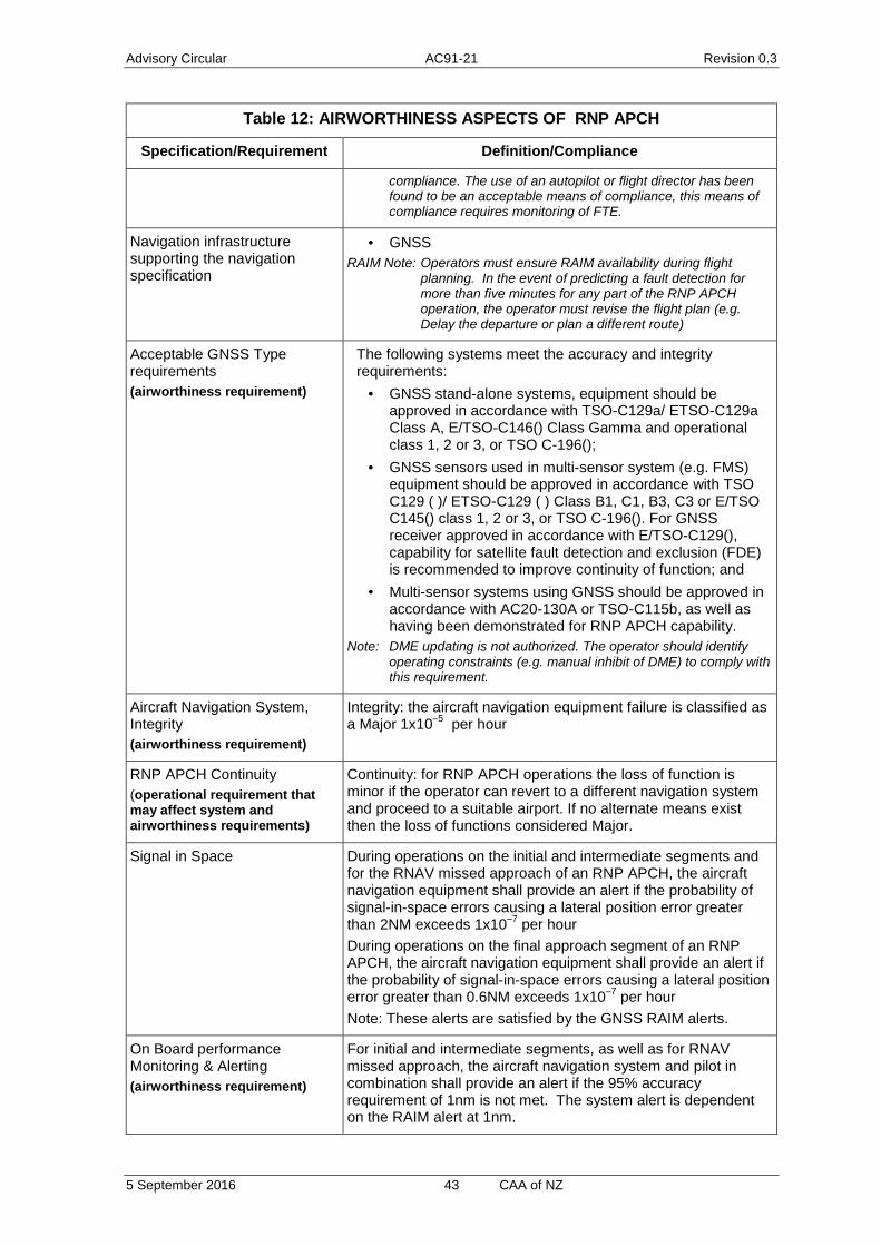
Advisory Circular AC91-21 Revision 0.3
5 September 2016 43 CAA of NZ
Table 12: AIRWORTHINESS ASPECTS OF RNP APCH
Specification/Requirement Definition/Compliance
compliance. The use of an autopilot or flight director has been found to be an acceptable means of compliance, this means of compliance requires monitoring of FTE.
Navigation infrastructure supporting the navigation specification
· GNSS RAIM Note: Operators must ensure RAIM availability during flight
planning. In the event of predicting a fault detection for more than five minutes for any part of the RNP APCH operation, the operator must revise the flight plan (e.g. Delay the departure or plan a different route)
Acceptable GNSS Type requirements (airworthiness requirement)
The following systems meet the accuracy and integrity requirements:
· GNSS stand-alone systems, equipment should be approved in accordance with TSO-C129a/ ETSO-C129a Class A, E/TSO-C146() Class Gamma and operational class 1, 2 or 3, or TSO C-196();
· GNSS sensors used in multi-sensor system (e.g. FMS) equipment should be approved in accordance with TSO C129 ( )/ ETSO-C129 ( ) Class B1, C1, B3, C3 or E/TSO C145() class 1, 2 or 3, or TSO C-196(). For GNSS receiver approved in accordance with E/TSO-C129(), capability for satellite fault detection and exclusion (FDE) is recommended to improve continuity of function; and
· Multi-sensor systems using GNSS should be approved in accordance with AC20-130A or TSO-C115b, as well as having been demonstrated for RNP APCH capability.
Note: DME updating is not authorized. The operator should identify operating constraints (e.g. manual inhibit of DME) to comply with this requirement.
Aircraft Navigation System, Integrity (airworthiness requirement)
Integrity: the aircraft navigation equipment failure is classified as a Major 1x10⁻⁵ per hour
RNP APCH Continuity (operational requirement that may affect system and airworthiness requirements)
Continuity: for RNP APCH operations the loss of function is minor if the operator can revert to a different navigation system and proceed to a suitable airport. If no alternate means exist then the loss of functions considered Major.
Signal in Space During operations on the initial and intermediate segments and for the RNAV missed approach of an RNP APCH, the aircraft navigation equipment shall provide an alert if the probability of signal-in-space errors causing a lateral position error greater than 2NM exceeds 1x10⁻⁷ per hour During operations on the final approach segment of an RNP APCH, the aircraft navigation equipment shall provide an alert if the probability of signal-in-space errors causing a lateral position error greater than 0.6NM exceeds 1x10⁻⁷ per hour Note: These alerts are satisfied by the GNSS RAIM alerts.
On Board performance Monitoring & Alerting (airworthiness requirement)
For initial and intermediate segments, as well as for RNAV missed approach, the aircraft navigation system and pilot in combination shall provide an alert if the 95% accuracy requirement of 1nm is not met. The system alert is dependent on the RAIM alert at 1nm.
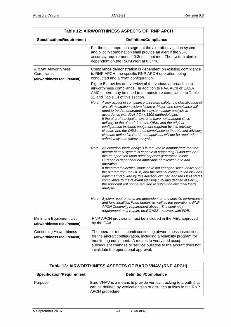
Advisory Circular AC91-21 Revision 0.3
5 September 2016 44 CAA of NZ
Table 12: AIRWORTHINESS ASPECTS OF RNP APCH
Specification/Requirement Definition/Compliance
For the final approach segment the aircraft navigation system and pilot in combination shall provide an alert if the 95% accuracy requirement of 0.3nm is not met. The system alert is dependent on the RAIM alert at 0.3nm.
Aircraft Airworthiness Compliance (airworthiness requirement)
Compliance demonstration is dependent on existing compliance to RNP APCH, the specific RNP APCH operation being conducted and aircraft configuration. Figure 5 provides an overview of the various approaches to airworthiness compliance. In addition to FAA AC’s or EASA AMC’s there may be need to demonstrate compliance to Table 12 and Table 14 of this section. Note: A key aspect of compliance is system safety, the classification of
aircraft navigation system failure is Major, and compliance will need to be demonstrated by a system safety analysis in accordance with FAA AC xx.1309 methodologies. If the aircraft navigation systems have not changed since delivery of the aircraft from the OEM, and the original configuration includes equipment required by this advisory circular, and the OEM states compliance to the relevant advisory circulars defined in Part 2, the applicant will not be required to submit a system safety analysis.
Note: An electrical loads analysis is required to demonstrate that the aircraft battery system is capable of supporting 30minutes or 60 minute operation upon primary power generation failure. Duration is dependent on applicable certification rule and operation. If the aircraft electrical loads have not changed since delivery of the aircraft from the OEM, and the original configuration includes equipment required by this advisory circular, and the OEM states compliance to the relevant advisory circulars defined in Part 2, the applicant will not be required to submit an electrical loads analysis.
Note: System requirements are dependent on the specific performance
and functionalities listed herein, as well as the operational RNP APCH Continuity requirement above. The continuity requirement may require dual GNSS receivers with FDE.
Minimum Equipment List (airworthiness requirement)
RNP APCH provisions must be included in the MEL approved by the CAA.
Continuing Airworthiness (airworthiness requirement)
The operator must submit continuing airworthiness instructions for the aircraft configuration, including a reliability program for monitoring equipment. A means to verify and accept subsequent changes or service bulletins to the aircraft does not invalidate the operational approval.
Table 13: AIRWORTHINESS ASPECTS OF BARO VNAV (RNP APCH)
Specification/Requirement Definition/Compliance
Purpose Baro VNAV is a means to provide vertical tracking to a path that can be defined by vertical angles or altitudes at fixes in the RNP APCH procedure.

Advisory Circular AC91-21 Revision 0.3
5 September 2016 45 CAA of NZ
Table 13: AIRWORTHINESS ASPECTS OF BARO VNAV (RNP APCH)
Specification/Requirement Definition/Compliance
The vertical path is contained in the instrument procedure within the RNP system navigation database The RNP system shall use barometric altimetry as a basis for its navigational capability.
Applicable Specification:
ICAO PBN Doc 9613 Volume II, Attachment A
VNAV System Altimetry Source (airworthiness requirement)
The Navigation system shall automatically determine aircraft position in the vertical plane from equipment that can include:
1. FAA TSO-C106, Air Data Computer; 2. 3. air data system, ARINC 706, Mark 5 Air Data System; 4. barometric altimeter system, DO-88 Altimetry, ED-26 MPS
for Airborne Altitude Measurements and Coding Systems, ARP-942 Pressure Altimeter Systems, ARP-920 Design and Installation of Pitot Static Systems for Transport Aircraft; and
5. Type certified integrated systems providing an air data system capability comparable to item 2.
Altimetry System Performance (airworthiness requirement)
Altimetry system performance is demonstrated separately through the static pressure systems certification (e.g. FAR or CS xx.1325), where performance must be 30 ft per 100 KIAS. Altimetry systems meeting such a requirement will satisfy the altimetry system error (ASE) requirements for Barometric VNAV. No further demonstration or compliance is necessary. The 99.7 per cent aircraft altimetry system error for each aircraft (assuming the temperature and lapse rates of the International Standard Atmosphere) must be less than or equal to the following:
Where H is the true altitude of the aircraft. Altimetry error refers to the electrical output and includes all errors attributable to the aircraft altimetry installation including position effects resulting from normal aircraft flight attitudes. In high performance aircraft, it is expected that altimetry correction will be provided. Such a correction should be done automatically. In lower performance aircraft, upgrading of the altimetry system may be necessary.
VNAV System Performance (airworthiness requirement)
The error of the airborne VNAV equipment (excluding altimetry, horizontal coupling and flight technical error) on a 99.7 per cent probability basis should be demonstrated to be less than:
Descent Along Specified Vertical Profile (angle) (ft)
At or below 5,000ft (MSL) 100
5,000ft to 10,000ft (MSL) 150
10,000ft to 15,000ft (MSL) 220
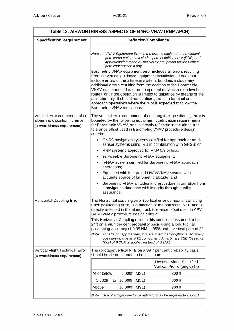
Advisory Circular AC91-21 Revision 0.3
5 September 2016 46 CAA of NZ
Table 13: AIRWORTHINESS ASPECTS OF BARO VNAV (RNP APCH)
Specification/Requirement Definition/Compliance
Note 1 VNAV Equipment Error is the error associated to the vertical
path computation. It includes path definition error (PDE) and approximation made by the VNAV equipment for the vertical path construction if any.
Barometric VNAV equipment error includes all errors resulting from the vertical guidance equipment installation. It does not include errors of the altimeter system, but does include any additional errors resulting from the addition of the Barometric VNAV equipment. This error component may be zero in level en-route flight if the operation is limited to guidance by means of the altimeter only. It should not be disregarded in terminal and approach operations where the pilot is expected to follow the Barometric VNAV indications.
Vertical error component of an along track positioning error (airworthiness requirement)
The vertical error component of an along track positioning error is bounded by the following equipment qualification requirements for Barometric VNAV, and is directly reflected in the along-track tolerance offset used in Barometric VNAV procedure design criteria:
· GNSS navigation systems certified for approach or multi-sensor systems using IRU in combination with GNSS; or
· RNP systems approved for RNP 0.3 or less; · serviceable Barometric VNAV equipment; · VNAV system certified for Barometric VNAV approach
operations; · Equipped with integrated LNAV/VNAV system with
accurate source of barometric altitude; and · Barometric VNAV altitudes and procedure information from
a navigation database with integrity through quality assurance.
Horizontal Coupling Error The Horizontal coupling error (vertical error component of along track positioning error) is a function of the horizontal NSE and is directly reflected in the along track tolerance offset used in APV BAROVNAV procedure design criteria. This Horizontal Coupling error in this context is assumed to be 24ft on a 99.7 per cent probability basis using a longitudinal positioning accuracy of 0.05 NM at 95% and a vertical path of 3°. Note For straight approaches, it is assumed that longitudinal accuracy
does not include an FTE component. An arbitrary TSE (based on NSE) of 0.2NM is applied instead of 0.3NM.
Vertical Flight Technical Error (airworthiness requirement)
The (pilotage)vertical FTE on a 99.7 per cent probability basis should be demonstrated to be less than:
Descent Along Specified Vertical Profile (angle) (ft)
At or below 5,000ft (MSL) 200 ft
5,000ft to 10,000ft (MSL) 300 ft
Above 10,000ft (MSL) 300 ft
Note Use of a flight director or autopilot may be required to support
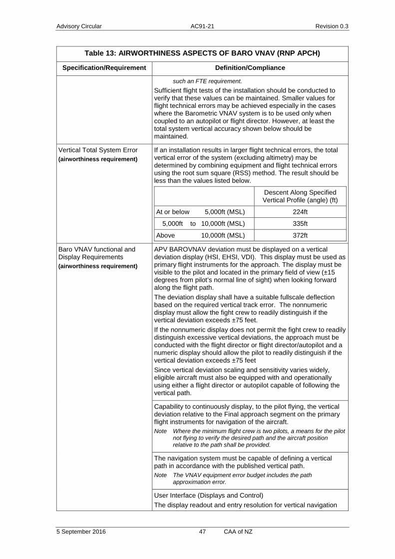
Advisory Circular AC91-21 Revision 0.3
5 September 2016 47 CAA of NZ
Table 13: AIRWORTHINESS ASPECTS OF BARO VNAV (RNP APCH)
Specification/Requirement Definition/Compliance
such an FTE requirement. Sufficient flight tests of the installation should be conducted to verify that these values can be maintained. Smaller values for flight technical errors may be achieved especially in the cases where the Barometric VNAV system is to be used only when coupled to an autopilot or flight director. However, at least the total system vertical accuracy shown below should be maintained.
Vertical Total System Error (airworthiness requirement)
If an installation results in larger flight technical errors, the total vertical error of the system (excluding altimetry) may be determined by combining equipment and flight technical errors using the root sum square (RSS) method. The result should be less than the values listed below.
Descent Along Specified Vertical Profile (angle) (ft)
At or below 5,000ft (MSL) 224ft
5,000ft to 10,000ft (MSL) 335ft
Above 10,000ft (MSL) 372ft
Baro VNAV functional and Display Requirements (airworthiness requirement)
APV BAROVNAV deviation must be displayed on a vertical deviation display (HSI, EHSI, VDI). This display must be used as primary flight instruments for the approach. The display must be visible to the pilot and located in the primary field of view (±15 degrees from pilot’s normal line of sight) when looking forward along the flight path. The deviation display shall have a suitable fullscale deflection based on the required vertical track error. The nonnumeric display must allow the fight crew to readily distinguish if the vertical deviation exceeds ±75 feet. If the nonnumeric display does not permit the fight crew to readily distinguish excessive vertical deviations, the approach must be conducted with the flight director or flight director/autopilot and a numeric display should allow the pilot to readily distinguish if the vertical deviation exceeds ±75 feet Since vertical deviation scaling and sensitivity varies widely, eligible aircraft must also be equipped with and operationally using either a flight director or autopilot capable of following the vertical path.
Capability to continuously display, to the pilot flying, the vertical deviation relative to the Final approach segment on the primary flight instruments for navigation of the aircraft. Note Where the minimum flight crew is two pilots, a means for the pilot
not flying to verify the desired path and the aircraft position relative to the path shall be provided.
The navigation system must be capable of defining a vertical path in accordance with the published vertical path. Note The VNAV equipment error budget includes the path
approximation error.
User Interface (Displays and Control) The display readout and entry resolution for vertical navigation

Advisory Circular AC91-21 Revision 0.3
5 September 2016 48 CAA of NZ
Table 13: AIRWORTHINESS ASPECTS OF BARO VNAV (RNP APCH)
Specification/Requirement Definition/Compliance
information shall be as follow:
Parameter Display Resolution
Entry Resolution
Altitude
Above altitude transition level Flight Level Flight Level
Below altitude transition level 1 foot 1 foot
Vertical Path Deviation 10 feet Not Applicable
Flight Path Angle 0.1° (*) 0.1°
Temperature* 1° 1°
*Temperature input is only for systems with temperature compensation functionality. The navigation database must contain all the necessary data/information to fly the published APV BAROVNAV approach. The navigation database must contain the waypoints and associated vertical information (e.g. VPA) for the procedure. Vertical Constraints associated with published procedures must be automatically extracted from the navigation database upon selecting the approach procedure.
Indication of loss of navigation (e.g. system failure) in the pilot’s primary field of view by means of a navigation warning flag or equivalent indicator on the vertical navigation display.
The aircraft must display barometric altitude from two independent altimetry sources, one in each pilots’ primary field of view. When single pilot operation is permitted, the two displays must be visible from the pilot position.
Temperature Limits (airworthiness requirement)
For aircraft using Barometric VNAV without temperature compensation to conduct the approach, low temperature limits are reflected in the procedure design and identified along with any high temperature limits on the charted procedure. Cold temperatures reduce the actual glide path angle, while high temperatures increase the actual glide path angle. Aircraft using Barometric VNAV with temperature compensation may disregard the temperature restrictions
Aircraft Airworthiness Compliance (airworthiness requirement)
Compliance demonstration is dependent on existing compliance to BARO VNAV (if any). Figure 6 provides an overview of the various approaches to airworthiness compliance. In addition to FAA AC’s or EASA AMC’s there may be need to demonstrate compliance to Table 13 of this section.
Minimum Equipment List (airworthiness requirement)
BARO VNAV provisions must be included in the MEL approved by the CAA.
Continuing Airworthiness (airworthiness requirement)
The operator must submit continuing airworthiness instructions for the aircraft configuration, including a reliability program for monitoring equipment. A means to verify and accept subsequent changes or service bulletins to the aircraft does not

Advisory Circular AC91-21 Revision 0.3
5 September 2016 49 CAA of NZ
Table 13: AIRWORTHINESS ASPECTS OF BARO VNAV (RNP APCH)
Specification/Requirement Definition/Compliance
invalidate the operational approval.
Table 14 : RNP APCH FUNCTIONAL REQUIREMENTS – NAVIGATION DISPLAYS AND FUNCTIONS
Ref Functional Requirement Explanation
(a) Navigation data, including a to/from indication, and a failure indication, must be displayed on a lateral deviation display (CDI, (E)HSI) and/or a navigation map display. These must be used as primary flight instruments for the navigation of the aircraft, for maneuver anticipation and for failure/status/integrity indication:
1. The displays must be visible to the pilot and located in the primary field of view (±15 degrees from the pilot’s normal line of sight) when looking forward along the flight path;
2. The lateral deviation display scaling should agree with any alerting and annunciation limits;
3. The lateral deviation display must also have a full-scale deflection suitable for the current phase of flight and must be based on the total system error (TSE) requirement. Scaling is ±1 NM for the initial and intermediate segments and ±0.3 NM for the final segment;
4. The display scaling may be set automatically by default logic or set to a value obtained from a navigation database. The full-scale deflection value must be known or must be available for display to the pilot commensurate with approach values;
5. As an alternate means, a navigation map display must give equivalent functionality to a lateral deviation display with appropriate map scales (scaling may be set manually by the pilot). To be approved, the navigation map display must be shown to meet the TSE requirements;
6. It is highly recommended that the course selector of the deviation display is automatically slaved to the RNAV computed path; Note This does not apply for installations
where an electronic map display contains a graphical display of the flight path and path deviation.
7. A flight director and/or autopilot is not required for this type of operation, however, if the lateral TSE cannot be demonstrated without these systems, it becomes mandatory. In this case, coupling to the flight director and/or automatic pilot from the RNP system must be clearly indicated at the cockpit level; and
8. Enhanced navigation display (e.g. electronic map display or enhanced EHSI) to improve lateral situational awareness, navigation
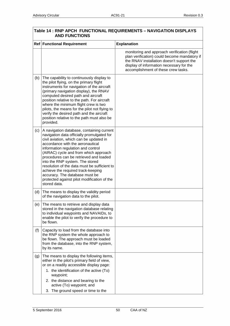
Advisory Circular AC91-21 Revision 0.3
5 September 2016 50 CAA of NZ
Table 14 : RNP APCH FUNCTIONAL REQUIREMENTS – NAVIGATION DISPLAYS AND FUNCTIONS
Ref Functional Requirement Explanation
monitoring and approach verification (flight plan verification) could become mandatory if the RNAV installation doesn’t support the display of information necessary for the accomplishment of these crew tasks.
(b) The capability to continuously display to the pilot flying, on the primary flight instruments for navigation of the aircraft (primary navigation display), the RNAV computed desired path and aircraft position relative to the path. For aircraft where the minimum flight crew is two pilots, the means for the pilot not flying to verify the desired path and the aircraft position relative to the path must also be provided.
(c) A navigation database, containing current navigation data officially promulgated for civil aviation, which can be updated in accordance with the aeronautical information regulation and control (AIRAC) cycle and from which approach procedures can be retrieved and loaded into the RNP system. The stored resolution of the data must be sufficient to achieve the required track-keeping accuracy. The database must be protected against pilot modification of the stored data.
(d) The means to display the validity period of the navigation data to the pilot.
(e) The means to retrieve and display data stored in the navigation database relating to individual waypoints and NAVAIDs, to enable the pilot to verify the procedure to be flown.
(f) Capacity to load from the database into the RNP system the whole approach to be flown. The approach must be loaded from the database, into the RNP system, by its name.
(g) The means to display the following items, either in the pilot’s primary field of view, or on a readily accessible display page:
1. the identification of the active (To) waypoint;
2. the distance and bearing to the active (To) waypoint; and
3. The ground speed or time to the

Advisory Circular AC91-21 Revision 0.3
5 September 2016 51 CAA of NZ
Table 14 : RNP APCH FUNCTIONAL REQUIREMENTS – NAVIGATION DISPLAYS AND FUNCTIONS
Ref Functional Requirement Explanation
active (To) waypoint.
(h) The means to display the following items on a readily accessible display page:
1. the display of distance between flight plan waypoints;
2. the display of distance to go; 3. the display of along-track distances;
and 4. the active navigation sensor type, if
there is another sensor in addition to the GNSS sensor.
(i) The capability to execute a “Direct to” function.
(j) The capability for automatic leg sequencing with the display of sequencing to the pilot.
(k) The capability to execute procedures extracted from the on-board database, including the capability to execute flyover and fly-by turns.
(l) The capability to automatically execute leg transitions and maintain tracks consistent with the following ARINC 424 path terminators, or their equivalent:
· ARINC 424 path terminators · Initial fix (IF) · Track to fix (TF) · Direct to fix (DF)
Note Path terminators are defined in ARINC Specification 424, and their application is described in more detail in RTCA/EUROCAE documents DO 236B/ED-75B and DO-201A/ED-77.
(m) The capability to display an indication of the RNP system failure, including the associated sensors, in the pilot’s primary field of view.
(n) The capability to indicate to the crew when NSE alert limit is exceeded (alert provided by the “on-board performance monitoring and alerting function”).
(o) The capability to automatically load numeric values for courses and tracks from the RNP system database.
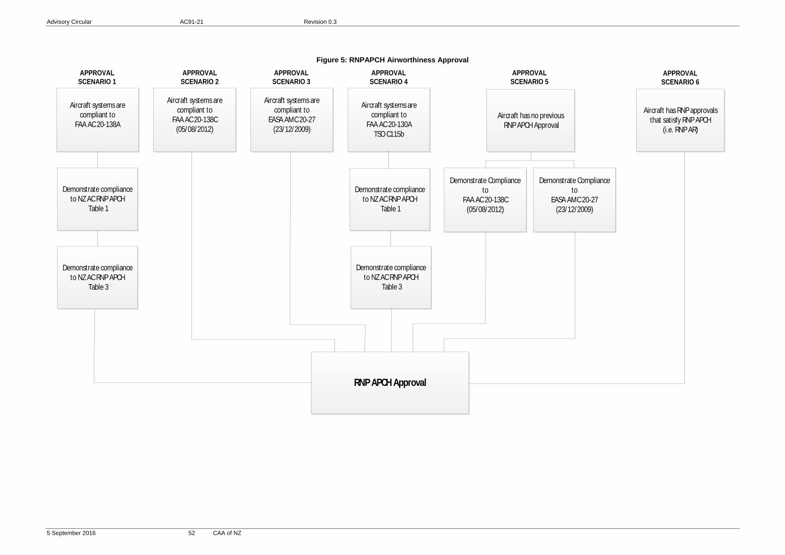
Advisory Circular AC91-21 Revision 0.3
5 September 2016 52 CAA of NZ
Figure 5: RNPAPCH Airworthiness Approval
APPROVAL SCENARIO 1
APPROVAL SCENARIO 2
APPROVAL SCENARIO 3
Aircraft systems are compliant to
FAA AC 20-138AAircraft has no previous
RNP APCH Approval
APPROVAL SCENARIO 4
APPROVAL SCENARIO 5
RNP APCH Approval
Demonstrate compliance to NZ AC RNP APCH
Table 1
Demonstrate compliance to NZ AC RNP APCH
Table 3
Aircraft systems are compliant to
FAA AC 20-138C(05/08/2012)
Aircraft systems are compliant to
EASA AMC 20-27(23/12/2009)
Aircraft systems are compliant to
FAA AC 20-130ATSO C115b
Demonstrate compliance to NZ AC RNP APCH
Table 1
Demonstrate compliance to NZ AC RNP APCH
Table 3
Demonstrate Compliance to
FAA AC 20-138C(05/08/2012)
Demonstrate Compliance to
EASA AMC 20-27(23/12/2009)
APPROVAL SCENARIO 6
Aircraft has RNP approvals that satisfy RNP APCH
(i.e. RNP AR)

Advisory Circular AC91-21 Revision 0.3
5 September 2016 53 CAA of NZ
Figure 6: RNPAPCH BARO VNAV Airworthiness Approval
APPROVAL SCENARIO 1
APPROVAL SCENARIO 2
APPROVAL SCENARIO 3
Aircraft systems are compliant to
FAA AC 20-129
Aircraft has no previous RNP APCH BARO VNAV
Approval
APPROVAL SCENARIO 4
APPROVAL SCENARIO 5
RNP APCH BARO VNAV Approval
Demonstrate compliance to NZ AC RNP APCH BARO
VNAV Table 2
Aircraft systems are compliant to
FAA AC 20-138CBARO VNAV
(05/08/2012)
Aircraft systems are compliant to
EASA AMC 20-27BARO VNAV
(23/12/2009)
Aircraft systems are compliant to
FAA AC 90-105
Demonstrate Compliance to
FAA AC 20-138CBARO VNAV
(05/08/2012)
Demonstrate Compliance to
EASA AMC 20-27BARO VNAV
(23/12/2009)
APPROVAL SCENARIO 6
Aircraft has RNP approvals that satisfy BARO VNAV(i.e. RNP AR APCH BARO
VNAV)
Demonstrate compliance to NZ AC RNP APCH BARO
VNAV Table 2

Advisory Circular AC91-21 Revision 0.3
5 September 2016 54 CAA of NZ
Part 3 Operator approval
The application and operator approval is described in Part 1, Process for Application and Approval.
The application shall include a copy of the operations manual/standard operating procedures required by rule 91.246(a) through (f).
In addition to the details specified in rule 91.246(e), the following must be included:
(a) Pilot currency requirements
(b) The operating procedures for the equipment to be used, including:
· Selection and checking of SIDs, routes, STARs, and approaches from the navigation database.
· Selection of the aerodrome of departure prior to take off to ensure a RNP 1 alert capability during departures.
· The actions to be taken in the event of inability to maintain PBN standards in flight due to RAIM outage, system malfunction, or intentional or unintentional interference.
(c) Control of the navigation database process
(d) Pre-flight planning including RAIM prediction if appropriate.
(e) Management of lateral deviation limits, RAIM limits and FTE
(f) The operator maintenance programme, procedures, and monitoring must satisfy the requirements of rule 91.246(e) for RNP operations and must include similar requirements for RNAV operations.
In addition to above, Part 119 operators must include in their checklists/manuals the operational and training requirements defined in ICAO Doc 9613 as follows:
RNAV1/2: Volume II, Part B, Chapter 3, 3.3.4 Operating Procedures Volume II, Part B, Chapter 3, 3.3.5 Pilot Knowledge & Training
RNP2: Volume II, Part C, Chapter 2, 2.3.4 Operating Procedures Volume II, Part C, Chapter 2, 2.3.5 Pilot Knowledge & Training
RNP1 Volume II, Part C, Chapter 3, 3.3.5 Operating Procedures Volume II, Part C, Chapter 3, 3.3.6 Pilot Knowledge & Training
RNP APCH Volume II, Part C, Chapter 5, A.5.3.4 Operating Procedures Volume II, Part C, Chapter 5, A.5.3.5 Pilot Knowledge & Training
BARO VNAV Volume II, Attachment A, 4.16 Operating Procedures Volume II, Attachment A, 4.21 Pilot Knowledge & Training

Advisory Circular AC91-21 Revision 0.3
5 September 2016 55 CAA of NZ
Oversight of operators Operators are responsible for monitoring their operation to ensure compliance with requirements and achievement of safety standards. This requires robust reporting of deviations and occurrences by crew members, and appropriate investigation and response by operators. For RNP operations, operators must monitor navigation performance and record deviations in accordance with rule 91.246. In the case of RNAV operations, operators are also encouraged to conduct navigation performance monitoring and report deviations to promote system safety The CAA will also conduct ongoing monitoring of operators to ensure compliance and safety. This will include auditing of operators systems and observation of flights. In the case of deviations, deficiencies or occurrences pertaining to operational approvals specified in this AC, the CAA will monitor to ensure the operator is taking appropriate corrective and preventative action. It is in the interest of all stakeholders that good communication of safety issues takes place to improve the system and avoid serious occurrences.
Part 4 Pilot approval
Pilots may not perform any of the types of operation specified in this AC unless they have been trained and certificated in accordance with Appendix III to AC61-17.
For pilots within a Part 119 organisation, pilot competency is achieved through operator compliance with their training programme and adherence to the standard operating procedures specified in their exposition.