advisory circular-lycaa/ac-ops.h 001caa.gov.ly/en/wp-content/uploads/pdf/ac-ops-h.001-jan...
TRANSCRIPT

Advisory Circular-LYCAA/AC-OPS.H 001
2
1. PURPOSE
This For the purpose of providing the operators with a single document contains acceptable
means of compliance , guidance material and information on Libyan off-shore installations to
accountable Organisations (Responsible for the safety oversight of helideck operating
companies), and to helideck Operators to meet the offshore operations requirements, the LYCAA
has adopted the Guidance Material contained in the (UK CAA CAP 437 (Standards for offshore
helicopter landing areas) This Advisory Circular is issued to reflect this policy and to ensure
unified approach for the development and implementation of the CAP 437.
The Libyan Civil Aviation Authority (LYCAA) Requirements for Air Operators, Operational
Requirements AIR-OPS, Part SPA (Subpart K-HOFO), are reflected in CAP 437 Appendix
material e.g. Appendix A is substantially based on GM2 SPA.HOFO.115 Use of offshore locations
2. Operational Regulations (Helicopters):
Provides regulation specifically for helicopter operations Helideck operators should make
reference to this document as an appreciation of the helicopter Operators’ responsibilities as
holder of an air operator certificate (AOC). Such operators shall ensure that all pilots are familiar
with the regulations and procedures pertinent to the performance of their duties.
3. Flight Safety Department (Operations section):
Flight Operations Managers shall assess the application of the operations for which the facility is
designed, in relation to LYCARs-AIR OPS (H). This will include the direction of flight; the
assessment of the obstacle environment on the basis of the intended use of a FATO; the
acceptance of the Declared Distances and obstacle limitation surfaces in relation to the most
critical helicopter type for which the helideck is intended.
One of the longer term intentions of this AC was to improve safety on helidecks.
4. REFERENCES:
4.1. The LYCARs Part SPA (Subpart K), Part NCC, and Part SPO.
4.2. ICAO ANNEX 6 Part III.
4.3. UK CAA CAP 437 (Copy attached and downloadable from:
http://publicapps.caa.co.uk/modalapplication.aspx?appid=11&mode=detail&id=523)
5. Applicability
This Advisory Circular is applicable to all Air Operators, and shall be effective from 15 February
2018.
-----------End-----------
Safety Regulation Group
Standards for offshore helicopter landing areas
CAP 437

CAP 437
December 2016
Published by the Civil Aviation Authority, 2016
Civil Aviation Authority,
Aviation House,
Gatwick Airport South,
West Sussex,
RH6 0YR.
You can copy and use this text but please ensure you always use the most up to date version and use it in context so as not to
be misleading, and credit the CAA.
ISBN 9780 11792 914 2
First published 1981
Second edition December 1993
Third edition October 1998
Fourth edition September 2002
Fifth edition August 2005
Sixth edition December 2008
Amendment 01/2010 April 2010
Amendment 02/2010 August 2010
Edition 7 May 2012
Amendment 01/2013 February 2013
Edition 8 December 2016
Enquiries regarding the content of this publication should be addressed to: [email protected]
Intelligence, Strategy & Policy, Safety & Airspace Regulation Group, Civil Aviation Authority, Aviation House, Gatwick Airport
South, West Sussex, RH6 0YR
The latest version of this document is available in electronic format at www.caa.co.uk, where you may also register for e-mail
notification of amendments.
CAP 437 Contents
December 2016 Page 1
Contents
Contents ............................................................................................................................... 1
Revision history ..................................................................................................................... 9
Foreword ............................................................................................................................. 13
Glossary of terms and abbreviations ................................................................................... 20
Chapter 1 ........................................................................................................................... 25
Introduction ......................................................................................................................... 25
History of development of criteria for offshore helicopter landing areas, 1964-1973 .... 25
Department of Energy and the Health and Safety Executive guidance on the design and
construction of offshore installations, 1973 onwards .................................................... 25
Applicability of standards in other cases .............................................................. 30
Worldwide application .......................................................................................... 30
Chapter 2 ........................................................................................................................... 32
Helicopter performance considerations ............................................................................... 32
General considerations ................................................................................................ 32
Safety philosophy ........................................................................................................ 32
Factors affecting performance capability ..................................................................... 33
Chapter 3 ........................................................................................................................... 34
Helicopter landing areas – Physical characteristics ............................................................. 34
General ....................................................................................................................... 34
Helideck design considerations – Environmental effects ............................................. 35
Introduction .......................................................................................................... 35
Helideck design guidance .................................................................................... 37
Design criteria ...................................................................................................... 37
Structural design .................................................................................................. 41
Loads ................................................................................................................... 43
Size and obstacle protected surfaces ................................................................... 46

CAP 437 Contents
December 2016 Page 2
Temporary combined operations ................................................................................. 52
Multiple platform configurations/location of standby vessels ........................................ 54
Surface ................................................................................................................ 55
Helicopter tie-down points .................................................................................... 60
Perimeter safety net ............................................................................................. 61
Access points ....................................................................................................... 62
Winching (hoist) operations .................................................................................. 64
Normally Unattended Installations (NUIs) ............................................................ 64
Criteria for parking areas ...................................................................................... 65
Chapter 4 ........................................................................................................................... 68
Visual aids .......................................................................................................................... 68
General ....................................................................................................................... 68
Helideck landing area markings ................................................................................... 70
Lighting ........................................................................................................................ 79
Perimeter lighting ................................................................................................. 80
Floodlighting, lit TD/PM circle and lit heliport identification ‘H’ marking ................. 81
Helideck status light system ................................................................................. 83
UPS requirement ................................................................................................. 86
Obstacles – Marking and lighting ................................................................................. 86
Chapter 5 ........................................................................................................................... 89
Helideck rescue and fire fighting facilities ............................................................................ 89
Introduction ................................................................................................................. 89
Key design characteristics – Principal agent ................................................................ 89
Use and maintenance of foam equipment ................................................................... 94
Complementary media ......................................................................................... 95
Normally unattended installations ................................................................................ 96
The management of extinguishing media stocks ......................................................... 98
Rescue equipment....................................................................................................... 98
Personnel levels ........................................................................................................ 100
CAP 437 Contents
December 2016 Page 3
Personal Protective Equipment (PPE) ....................................................................... 100
Training ..................................................................................................................... 101
Emergency procedures ............................................................................................. 101
Further advice ........................................................................................................... 101
Chapter 6 ......................................................................................................................... 102
Miscellaneous operational standards ................................................................................ 102
Landing area height above water level ...................................................................... 102
Wind direction (vessels) ............................................................................................ 102
Helideck movement ................................................................................................... 102
Helideck motion reporting .................................................................................. 105
Meteorological information ......................................................................................... 106
Meteorological observations .............................................................................. 106
Assessment of wind speed and direction ........................................................... 107
Reporting of meteorological information ............................................................. 107
Pre-flight weather reports ................................................................................... 107
Radio messages ................................................................................................ 108
Collection and retention of meteorological information ....................................... 108
Real-time web-based systems ........................................................................... 109
Meteorological observer training ........................................................................ 109
Calibration of meteorological equipment sensors ............................................... 109
Location in respect to other landing areas in the vicinity ............................................ 110
Control of crane movement in the vicinity of landing areas ........................................ 111
General precautions .................................................................................................. 111
Installation/Vessel helideck operations manual and general requirements ................ 112
Helicopter operations support equipment .................................................................. 112
Chapter 7 ......................................................................................................................... 114
Helicopter fuelling facilities – Systems design and construction ........................................ 114
General ..................................................................................................................... 114
Product identification ................................................................................................. 115
CAP 437 Contents
December 2016 Page 4
Fuelling system description ................................................................................ 115
Design considerations ............................................................................................... 116
Static storage tanks ........................................................................................... 117
Sample reclaim tank .......................................................................................... 120
Delivery system ................................................................................................. 121
Transfer system ................................................................................................. 133
Transit tanks ...................................................................................................... 134
Chapter 8 ......................................................................................................................... 138
Helicopter fuelling facilities – Maintenance and fuelling procedures .................................. 138
Fuel quality sampling and sample retention ............................................................... 139
Fuel sample containers ...................................................................................... 139
Fuel sampling .................................................................................................... 140
Fuel sample retention ........................................................................................ 144
Decanting from sample reclaim tanks ................................................................ 145
Recommended maintenance schedules .................................................................... 146
Transit tanks ...................................................................................................... 146
Static storage tanks ........................................................................................... 149
Delivery systems ................................................................................................ 151
Miscellaneous inspection frequency ................................................................... 163
System breakdown .................................................................................................... 164
Sample reclaim tanks ................................................................................................ 165
Transit tanks .............................................................................................................. 166
Filling of transit tanks ......................................................................................... 166
Receipt of transit tanks offshore ......................................................................... 167
Decanting from transit tanks to static storage ..................................................... 168
Set-up for fuelling direct from transit tanks ......................................................... 169
Set-up for fuelling from static storage tanks ....................................................... 170
Static storage tank draining ................................................................................ 171
Long term storage of aviation fuel .............................................................................. 173
CAP 437 Contents
December 2016 Page 5
Aircraft refuelling ....................................................................................................... 173
Quality control documentation ................................................................................... 176
Chapter 9 ......................................................................................................................... 178
Helicopter landing areas on vessels .................................................................................. 178
Vessels supporting offshore mineral workings and specific standards for landing areas
on merchant vessels .................................................................................................. 178
Amidships helicopter landing areas – Purpose-built or non-purpose-built ship’s
centreline ................................................................................................................... 179
Size and obstacle environment .......................................................................... 179
Helicopter landing area marking and lighting ...................................................... 182
Ship’s side non-purpose-built landing area ................................................................ 184
Ship’s side non-purpose-built landing area markings ......................................... 186
Night operations ........................................................................................................ 188
Poop deck operations ................................................................................................ 188
Chapter 10 ....................................................................................................................... 189
Helicopter winching areas on vessels and on wind turbine platforms ................................ 189
Winching areas on vessels ........................................................................................ 189
Design and obstacle restriction .......................................................................... 189
Visual aids ......................................................................................................... 190
Obstructions ....................................................................................................... 192
Hoisting above accommodation spaces ............................................................. 192
Helicopter winching areas on wind turbine platforms ................................................. 192
Platform design .................................................................................................. 193
Obstacle restriction ............................................................................................ 196
Visual aids ......................................................................................................... 196
Further operational conditions ................................................................................... 200
Appendix A ...................................................................................................................... 201
Use of offshore locations ................................................................................................... 201
AMC1 SPA.HOFO.115 .............................................................................................. 201
General .............................................................................................................. 201

CAP 437 Contents
December 2016 Page 6
GM1 SPA.HOFO.115 ................................................................................................ 207
Appendix B ...................................................................................................................... 209
Bibliography ...................................................................................................................... 209
References ................................................................................................................ 209
Health and Safety Executive .............................................................................. 209
International Civil Aviation Organization ............................................................. 210
Other publications .............................................................................................. 210
Civil Aviation Authority – CAPs, research papers and policy statements ............ 211
Sources ..................................................................................................................... 213
Appendix C ...................................................................................................................... 215
Specification for helideck lighting scheme comprising perimeter lights, lit
touchdown/positioning marking and lit heliport identification marking ................................ 215
Overall operational requirement................................................................................. 215
Definitions .......................................................................................................... 217
The perimeter light requirement ................................................................................. 218
The touchdown/positioning marking circle requirement ............................................. 219
The heliport identification marking requirement ......................................................... 223
General characteristics .............................................................................................. 226
Requirements .................................................................................................... 226
Other considerations ................................................................................................. 227
Appendix D ...................................................................................................................... 229
Helideck fire fighting provisions for existing NUI assets on the UK continental shelf ......... 229
Appendix D1 .............................................................................................................. 229
Introduction ........................................................................................................ 229
Definitions .......................................................................................................... 232
H1/H2 scheme details ........................................................................................ 232
Appendix D2 .............................................................................................................. 235
Letter to industry July 2011 ................................................................................ 235
Appendix E ...................................................................................................................... 258

CAP 437 Contents
December 2016 Page 7
Additional guidance relating to the provision of meteorological information from offshore
installations ....................................................................................................................... 258
Introduction ............................................................................................................... 258
Contents and standardisation of the weather reports issued by each offshore installation
.................................................................................................................................. 258
Wind .................................................................................................................. 258
Visibility .............................................................................................................. 259
Lightning ............................................................................................................ 259
Present weather ................................................................................................. 259
Cloud ................................................................................................................. 261
Air temperature and dew point ........................................................................... 261
QNH and QFE (atmospheric pressure) .............................................................. 261
Significant wave height ...................................................................................... 261
Pitch, roll, helideck inclination and significant heave rate ................................... 262
Remarks ............................................................................................................ 262
Missing or unavailable information ..................................................................... 262
Example offshore report ............................................................................................ 262
Definition of an offshore meteorological observer ...................................................... 265
Applicability of meteorological equipment to helideck categories ............................... 265
Design, siting and back-up requirements for meteorological equipment installed in
offshore installations .................................................................................................. 266
Wind speed and direction ................................................................................... 266
Temperature ...................................................................................................... 268
Pressure ............................................................................................................ 269
Visibility .............................................................................................................. 271
Present weather sensor ..................................................................................... 273
Cloud ................................................................................................................. 274
Calibration, maintenance and servicing periods ................................................. 276
Appendix F ...................................................................................................................... 277

CAP 437 Contents
December 2016 Page 8
Procedure for authorising offshore helicopter landing areas – letter to offshore helicopter
operators, October 2011 ................................................................................................... 277
Appendix G ...................................................................................................................... 279
Guidance for helideck floodlighting systems ...................................................................... 279
Introduction ............................................................................................................... 279
General considerations for helideck floodlighting ....................................................... 279
Improved floodlighting system ................................................................................... 281
Appendix H ...................................................................................................................... 283
Risk assessment for helicopter operations to helidecks in the UKCS which are sub-1D .... 283
Appendix I ....................................................................................................................... 291
CAA protocol for operations against operating status lights or black decks ....................... 291
Appendix J ...................................................................................................................... 296
Specification for a helicopter hoist status light ................................................................... 296
Application ................................................................................................................. 296
Operational requirements .......................................................................................... 296
Location ............................................................................................................. 296
Performance ...................................................................................................... 297
Day/Night operation ........................................................................................... 297
Characteristics ........................................................................................................... 298
Appendix K ...................................................................................................................... 301
Helideck friction survey protocol ........................................................................................ 301
Introduction ............................................................................................................... 301
Friction measuring equipment ................................................................................... 301
Survey procedure ...................................................................................................... 302
General .............................................................................................................. 302
Preparation ........................................................................................................ 302
Survey ............................................................................................................... 302
Presentation of results ............................................................................................... 303

CAP 437 Revision history
December 2016 Page 9
Revision history
Edition 1 September 1981
The first edition of CAP 437 was published to give guidance on the criteria applied by
the CAA in assessing the standard of helicopter offshore landing areas for worldwide
use by helicopters registered in the UK. The criteria in the CAP relating to fixed and
mobile installations in the area of the UK Continental Shelf were based on the
helicopter landing area standards of the Department of Energy. Additional criteria
were given relating to vessels used in the support of offshore mineral exploitation
and tankers, cargo vessels and passenger vessels which were not subject to the
Department of Energy certification. These criteria were evolved following
consultation with the Department of Trade (Marine Division) and the Inter-
governmental Maritime Consultative Organisation. In addition to explaining the
reasons behind the chosen criteria, the first edition of CAP 437 described their
application to particular classes of landing area.
Edition 2 December 1993
The guidance in CAP 437 was revised in the light of International Civil Aviation
Organization (ICAO) recommendations and Health and Safety Executive (HSE)/CAA
experience gained from offshore helideck inspections.
Edition 3 October 1998
Amendments were made to incorporate the results of valuable experience gained by
CAA staff during three and a half years of offshore helideck inspecting with the HSE
and from cooperation with the British Helicopter Advisory Board (BHAB). Analysis of
the results of the inspection regime, completed in April 1995, resulted in changes to
the way in which helidecks were authorised for use by helicopter operators. Other
changes reflected knowledge gained from accidents, incidents, occurrences and
research projects. The section concerning the airflow environment, and the impact
on this environment from exhaust and venting systems, was revised. Also the
paragraph numbering was changed for easier reference.
Edition 4 September 2002
The CAP was amended to incorporate new house-style.
CAP 437 Revision history
December 2016 Page 10
Edition 5 August 2005
The CAP was extensively revised to incorporate valuable experience gained from
CAA funded research projects conducted with the support of the UK offshore
industry into improved helideck lighting, helideck environmental effects and
operations to moving helidecks. The sections concerning helideck lighting were
considerably revised to ensure that UK good practice adequately reflected the
changes made in 2004 to the ICAO Standards and Recommended Practices
(SARPs) for TLOF lighting. The fifth edition also pulled together revised
requirements harmonised amongst North Sea States as a result of initiatives taken
by the Group of Aerodrome Safety Regulators (GASR) Helideck Working Group.
Edition 6 December 2008
The sixth edition is revised to incorporate further results of valuable experience
gained from CAA funded research projects conducted with the support of the UK
offshore industry into improved helideck lighting and the conclusion of projects,
jointly funded with the Health and Safety Executive (HSE), relating to offshore
helideck environmental issues. In respect of helideck lighting, a detailed specification
for stage 2 lighting systems (addressing illumination of the heliport identification ‘H’
marking and the Touchdown/Positioning Marking Circle) is provided in an Appendix;
and a new reference to the final specification for helideck status lights systems is
provided in Chapter 4. In regard to now-completed helideck environmental projects,
Chapter 3 provides formal notification of the new turbulence criterion and the
removal of the long-standing vertical flow criterion.
The sixth edition has also been amended to include new ICAO SARPs relating to
offshore helidecks and shipboard heliports, which generally become applicable from
November 2009. This edition has also been revised to include material which is part
of the fourth edition of the International Chamber of Shipping (ICS) Guide to
Helicopter/Ship Operations, published in December 2008. For the first time,
provisions are included for the design of winching area arrangements located on
wind turbine platforms.
Edition 6 amendment 01/2010 April 2010
This amendment was issued to provide operators with Additional Guidance Relating

CAP 437 Revision history
December 2016 Page 11
to the Provision of Meteorological Information from Offshore Installations. Editorial
amendments convenient to be included at this time have also been incorporated.
Edition 6 amendment 01/2010 August 2010
This amendment was issued to correct an error in Chapter 10, paragraph 2 that
referred to a requirement for a medium intensity (rather than a low intensity) steady
red obstruction light. The opportunity has been taken to update part of Chapter 4
relating to helideck lighting and part of Chapter 5 relating to the location of foam-
making equipment. Editorial amendments convenient to be included at this time have
also been incorporated.
Edition 7 May 2012
The seventh edition is revised to incorporate the full and final specification for the
Helideck Lighting Scheme comprising Perimeter Lights, Lit Touchdown/Positioning
Marking Circle and Lit Heliport Identification 'H' Marking.
The seventh edition has also been updated to reflect ICAO SARPs for Annex 14
Volume II due to become applicable for States from November 2013. Provisions for
the design of winching area arrangements located on wind turbines, first introduced
at the sixth edition, has been reviewed and updated to reflect current best practice
with the benefit of lessons learned through various industry forums attended since
2008.
Edition 7 amendment 01/2013 February 2013
This amendment was issued to clarify aspects of the final specification and
installation arrangements for the Lit Touchdown/Positioning Marking Circle and Lit
Heliport Identification Marking. Further amendments convenient to be included at this
time have also been incorporated.
Edition 8 December 2016
The eighth edition presents several new topics not previously addressed in CAP 437
including a risk assessment for helicopter operations to helidecks in the UKCS which
are sub-1D and criteria for parking areas. In addition there is a comprehensive
update on the section related to helideck surface including new friction requirements
for flat helidecks with micro-texture finishes and for profiled helidecks. An update on
best practice for temporary combined operations, multiple platform configurations

CAP 437 Revision history
December 2016 Page 12
and helideck movement are also included. This amendment is issued to present the
final specification and the installation arrangements for the Lit Touchdown/
Positioning Marking Circle and Lit Heliport Identification Marking. Finally the
European Aviation Safety Agency (EASA) Requirements for Air Operators,
Operational Requirements Part-OPS, Annex VI Part SPA (AMC1 SPA.HOFO.115
Use of offshore locations) are reflected in Appendix material.

CAP 437 Foreword
December 2016 Page 13
Foreword
1. This publication, re-named Standards for Offshore Helicopter Landing
Areas at seventh edition, has become an accepted world-wide source of
reference. The amendments made to the eighth edition introduce several
new topics not previously addressed by CAP 437 including a risk
assessment for helicopter operations to helidecks in the UKCS which are
sub-1D and criteria for parking areas. In addition there is a comprehensive
update on the section related to helideck surfaces including new friction
requirements for flat helidecks with micro-texture finishes and for profiled
helidecks. An update on best practice for temporary combined operations,
multiple platform configurations and operations to moving helidecks are
also included. The European Aviation Safety Agency (EASA)
Requirements for Air Operators, Operational Requirements Part-OPS,
Annex VI Part SPA, which were adopted into EU legislation during
summer 2016, are reflected in CAP 437 Appendix material i.e. Appendix A
is substantially based on AMC1 SPA.HOFO.115 Use of offshore
locations. The eighth edition amendment presents the final specification
and installation arrangements for the Lit Touchdown/Positioning Marking
Circle and Lit Heliport Identification ‘H’ Marking. As a consequence of the
introduction-to-service of new lighting systems, the CAA, with the full
support of the offshore industry, is committed to assist implementation on
all existing and new-build installations operating on the UK Continental
Shelf (UKCS) by no later than 31st March 2018 if night operations are to
continue to be permitted after this date. The CAA believes that the new
lighting scheme represents a significant safety enhancement over
traditional floodlighting and is working actively with all sectors of the
industry to encourage prompt deployment of the new lighting scheme. The
TD/PM Circle and Heliport Identification ('H') Marking lighting forms an
acceptable alternative to floodlights in International Civil Aviation
Organization (ICAO) Annex 14 Volume II and provision of an equivalent
circle and H scheme that meets national requirements will effectively be

CAP 437 Foreword
December 2016 Page 14
mandated in Europe, by mid-2018, through the implementation of the
European Aviation Safety Agency (EASA) Requirements for Air
Operators, Operational Requirements Part-OPS, Annex VI Part SPA,
AMC1 SPA.HOFO.115 Use of offshore locations.
2. At international level the UK CAA continues to participate in the ICAO
Heliport Design Working Group (HDWG) tasked with the substantial
revision of Annex 14 Volume II including a review of the International
Standards and Recommended Practices relating to offshore helidecks
and shipboard heliports, and supporting guidance material in the Heliport
Design and Services Manual (doc. 9261). The latest tranche of
amendments were approved by the ICAO Air Navigation Commission
(ANC) in 2015, adopted by the Council in March 2016, became effective
in July and with applicability to States from November 2016. The
amendments, albeit fairly minor, reflect the size of TD/PM Circle and
Heliport Identification ('H') painted markings, which may be a smaller size
on new helidecks and shipboard heliports which have a D-value below
16.0m. A new ICAO recommendation related to the drive to reduce the
height of essential non-frangible objects around a helideck and shipboard
heliport, is supported by this 8th Edition of CAP 437, with a
recommendation for implementation on new builds by no later than 10
November 2018. Current work programmes of the ICAO HDWG include a
comprehensive review of Chapter 6, Rescue and Fire-Fighting Services,
and the supporting guidance in the Heliport Design & Services Manual.
This substantial piece of work is due to complete in late 2017/ early 2018
and it is anticipated that developments in best practice will be addressed
in chapter 5 of a forthcoming update to CAP 437 8th Edition.
3. Also at international level, the UK CAA participated in a technical group
that consisted of marine and aviation experts tasked with reviewing and
updating the International Chamber of Shipping’s (ICS) Guide to
Helicopter/Ship Operations. A fourth edition of the Guide was published in
December 2008 and current best practice from the ICS Guide is reflected
in Chapters 9 and 10 of the eighth edition of CAP 437. The UK CAA is

CAP 437 Foreword
December 2016 Page 15
grateful to the ICS for providing a number of the figures for these
chapters.
4. In February 2014, following a series of fatal accidents and incidents in the
North Sea, CAA commissioned and published a safety review of offshore
public transport helicopter operations in support of the exploitation of oil
and gas; reported in CAP 1145. In regard to helidecks it was noted that
the CAA’s drive to certificate helidecks had received the support of the
helicopter operators who viewed a tighter control of the helideck and its
environment as a positive step to improving safety. The report added that
“certification directly by the CAA or through an appropriately qualified
entity would provide the framework for raising standards on helidecks.” As
a consequence an action (A13) was raised for CAA to assume
responsibility for the certification of UK helidecks and to consult with
industry on how to achieve this. The outcome from the subsequent
consultation conducted via CAP 1295 “Consultation: The CAA's intention
to assume responsibility for the certification of UK helidecks”, was
reported in September 2016 in CAP 1386 “Safety review of offshore public
transport helicopter operations in support of the exploitation of oil and gas.
Progress report: 2016”. Summarising the outcome from the CAP 1295
consultation in May 2015, CAP 1386 noted that, although the CAA-
chaired Offshore Helicopter Safety Action Group (OHSAG) was
supportive of a certification scheme, it could not be implemented without
appropriate legal authority which it was estimated would take several
years to establish. As a consequence, in the shorter term CAA plans to
enhance oversight of helidecks using existing CAA resources and working
towards the final desired solution in collaboration with the Helideck
Certification Agency (HCA).
5. Since the mid-1990’s the offshore helicopter operators, in seeking to
discharge the duty placed on them by the UK Air Navigation Order (ANO)
have used the services of the HCA to inspect and certificate helidecks
operated on the UKCS, to satisfy the helicopter operators that they are ‘fit
for purpose’. Previous editions of CAP 47 have noted that the procedure
described for authorising the use of helidecks on fixed and floating
CAP 437 Foreword
December 2016 Page 16
installations operating on the UKCS is co-ordinated by the HCA in a
process which involves OGUK; the British Rig Owners’ Association
(BROA); and the International Association of Drilling Contractors (IADC)
and members’ individual owner/operator safety management systems.
RenewablesUK can now be added to the list as HCA also authorise
helidecks which are used to service the growing offshore renewable
energy sector.
6. In addition to administering the certification process on behalf of the
helicopter operators, HCA presently assumes the role of chairing the
Helideck Steering Committee (HSC) which includes senior operational
flying staff from all the offshore helicopter operators. In future, determining
the governance structure of the HSC, and how (specifically by whom) the
Helideck Limitations List (HLL) is controlled and amended, will form part of
the detailed review needed to develop an effective CAA-led scheme for
the certification of helidecks. Currently the HCA Helideck Steering
Committee functions to ensure that standardisation is achieved between
the offshore helicopter operators in the development and application of
operational policies and limitations and that non-compliances, where
identified, are treated in a consistent manner by each operator. The HCA
publishes these in the Helideck Limitations List (HLL) which contains
details of known helidecks including any operator-agreed limitations
applied to specific helidecks in order to compensate for any failings or
deficiencies in meeting CAP 437 criteria such that the safety of flights is
not compromised.
7. Accepting that the process described above is an industry-agreed system,
the legal responsibility for the suitability of offshore helicopter landing
areas, ahead of the introduction of a legally binding certification scheme,
rests ultimately with the helicopter operators. The CAA accepts the
process described above as being an acceptable way in which the
assessment of the CAP 437 criteria can be made, but is seeking to
develop the model into a CAA-led certification scheme. The CAA, in
discharging its regulatory responsibility, will audit the application of the
process on which the helicopter operator relies. As part of the flight

CAP 437 Foreword
December 2016 Page 17
operations function for the oversight of the AOC holder, the CAA intends
to forge closer ties with the HCA to review and audit their procedures and
processes, to assess how they assist the present legal responsibilities
and requirements of the offshore helicopter operators, and how these
arrangements might be used to inform a future CAA-led scheme. At the
present time helidecks on the UKCS continue to be regarded as
‘unlicensed landing areas’ and offshore helicopter operators are required
to satisfy themselves that each helideck to which they operate is fit for
purpose.
8. CAP 437 presents the criteria required by the CAA in assessing the
standards of offshore helicopter landing areas for world-wide use by
helicopters registered in the UK. These landing areas may be located on:
fixed offshore installations;
mobile offshore installations;
vessels supporting offshore mineral exploitation;
offshore wind farms; or
other vessels, e.g. tankers, cargo vessels, passenger vessels.
9. If an offshore helideck does not meet the criteria in CAP 437, or if a
change to the helideck environment is proposed, the case should be
referred to the HCA in the first instance to enable them to collate
information on behalf of the helicopter operators so that the process for
authorising the use of the helideck can be completed in a timely fashion.
Early consultation with the HCA is essential if maximum helicopter
operational flexibility is to be realised and incorporated into the installation
design philosophy. It is important that changes are not restricted to
consideration of the physical characteristics and obstacle protected
surfaces of the helideck. Of equal, and sometimes even greater,
importance are changes to the installation or vessel, and to adjacent
installation or vessel structures which may affect the local atmospheric
environment over the helideck (and adjacent helidecks) or approach and
take-off paths. In the case of ‘new-builds’ or major modifications to
existing Installations that may have an effect on helicopter operations, the

CAP 437 Foreword
December 2016 Page 18
CAA has published guidance on helideck design considerations in CAA
Paper 2008/03, which is available to assist with the interpretation and the
application of criteria stated in CAP 437.
10. The criteria in this publication relating to fixed and mobile installations in
the area of the UKCS, whether they are operating for Oil and Gas or
renewable energy sectors, provide standards which are accepted by the
HSE and referred to in HSE offshore legislation. The criteria address
minimum standards required in order to achieve a clearance which will
attract no helicopter performance (payload) limitations. CAP 437 is an
amplification of internationally agreed standards contained in ICAO Annex
14 to the Convention on International Civil Aviation, Volume II, ‘Heliports’.
Additionally it provides advice on ‘best practice’ obtained from many
aviation sources. ‘Best practice’, naturally, should be moving forward
continuously and it should be borne in mind that CAP 437 reflects ‘current’
best practice at the time of publication. There may be alternative
equivalent means of meeting the criteria presented in CAP 437 and these
will be considered on their merits.
11. Additional criteria are given relating to vessels used in support of offshore
mineral exploitation or renewable energy, which are not necessarily
subject to HSE offshore regulation and also for other vessels such as
tanker, cargo and passenger vessels.
12. In this publication the term ‘helideck’ refers to all helicopter landing areas
on fixed or floating offshore facilities used for the exploration or
exploitation of oil and gas. For helicopter landing areas on vessels the
term 'shipboard heliport' may be used in preference to ‘helideck’.
13. Whenever the term ‘CAA’ is used in this publication, it means the UK Civil
Aviation Authority unless otherwise indicated.
14. As standards for best practice, this document applies the term “should”
when referring to either an ICAO Standard or a Recommended Practice.
The term “may” is used when a variation or alternative approach could be
acceptable to the CAA. The UK HSE accepts that conformance with CAP

CAP 437 Foreword
December 2016 Page 19
437 will demonstrate compliance with applicable offshore regulations.
CAP 437 is under continuous review resulting from technological
developments and experience; comments are always welcome on its
application in practice. The CAA should be contacted on matters relating
to interpretation and applicability of these standards and Aviation Law.

CAP 437 Glossary of terms and abbreviations
December 2016 Page 20
Glossary of terms and abbreviations
AAIB Air Accidents Investigation Branch
AMSL Above Mean Sea Level
ANC Air Navigation Commission
ANO The Air Navigation Order
AOC Air Operator’s Certificate
CAFS Compressed Air Foam System
CFD Computational Fluid Dynamics
Class societies Organisations that establish and apply technical standards to the
design and construction of marine facilities including ships.
D-circle A circle, usually hypothetical unless the helideck itself is circular,
the diameter of which is the D-value of the largest helicopter the
helideck is intended to serve.
D-value The largest overall dimension of the helicopter when rotors are
turning. This dimension will normally be measured from the most
forward position of the main rotor tip path plane to the most
rearward position of the tail rotor tip path plane (or the most
rearward extension of the fuselage in the case of Fenestron or
Notar tails).
DIFFS Deck Integrated Fire Fighting System(s)
DSV Diving Support Vessel
EASA European Aviation Safety Agency
Falling 5:1 gradient A surface extending downwards on a gradient of 5:1 measured
from the edge of the safety netting located around the landing
area below the elevation of the helideck to water level for an arc of
not less than 180° that passes through the centre of the landing
area and outwards to a distance that will allow for safe clearance
from obstacles below the helideck in the event of an engine failure
for the type of helicopter the helideck is intended to serve. For

CAP 437 Glossary of terms and abbreviations
December 2016 Page 21
helicopters operated in Performance Class 1 or 2 the horizontal
extent of this distance will be compatible with the one-engine
inoperative capability of the helicopter type to be used.
FMS Fixed Monitor System
FOD Foreign Object Debris/Damage
FPSO Floating Production Storage and Offloading units
FSU Floating Storage Unit
HCA Helideck Certification Agency. The HCA is the certifying agency
acting on behalf of the UK offshore helicopter operators that
audits and inspects all helidecks and shipboard heliports on
offshore installations and vessels operating in UK waters to the
standards laid down in CAP 437.
HDWG Heliport Design Working Group (of ICAO Aerodromes panel)
Helideck A helicopter landing area located on a fixed or floating offshore
facility.
HHOP Helicopter Hoist Operations Passengers
HLAC The Helicopter Landing Area Certificate issued by the HCA, and
required by UK offshore helicopters operators, to authorise the
use of a helideck or shipboard heliport.
HLL Helideck Limitations List. Published and distributed by the HCA in
UKCS or other National Authority accepted bodies in other
European States.
HLO Helicopter Landing Officer
HMS Helideck Motion System
HSC Health and Safety Commission
HSE Health and Safety Executive
IATA International Air Transport Association
ICAO International Civil Aviation Organization
ICP Independent and competent person as defined in the Offshore
Installations (Safety Case) Regulations 2005 who is selected to
perform functions under the verification scheme.
CAP 437 Glossary of terms and abbreviations
December 2016 Page 22
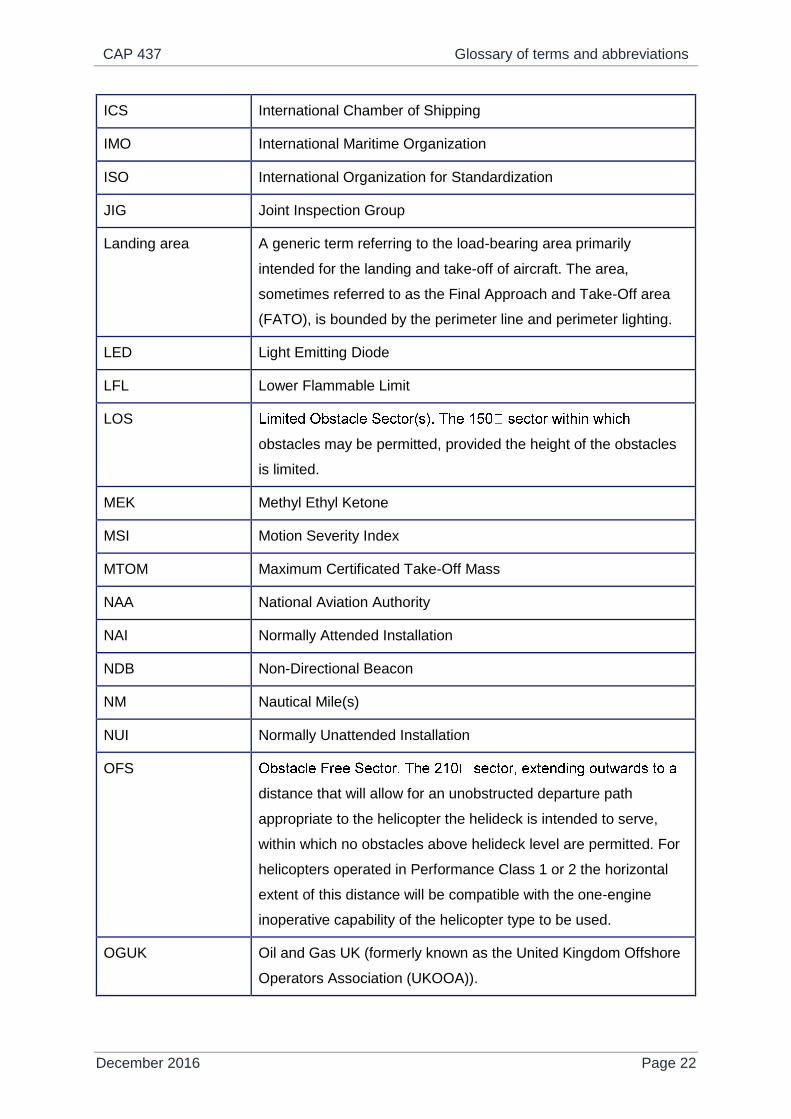
ICS International Chamber of Shipping
IMO International Maritime Organization
ISO International Organization for Standardization
JIG Joint Inspection Group
Landing area A generic term referring to the load-bearing area primarily
intended for the landing and take-off of aircraft. The area,
sometimes referred to as the Final Approach and Take-Off area
(FATO), is bounded by the perimeter line and perimeter lighting.
LED Light Emitting Diode
LFL Lower Flammable Limit
LOS
obstacles may be permitted, provided the height of the obstacles
is limited.
MEK Methyl Ethyl Ketone
MSI Motion Severity Index
MTOM Maximum Certificated Take-Off Mass
NAA National Aviation Authority
NAI Normally Attended Installation
NDB Non-Directional Beacon
NM Nautical Mile(s)
NUI Normally Unattended Installation
OFS
distance that will allow for an unobstructed departure path
appropriate to the helicopter the helideck is intended to serve,
within which no obstacles above helideck level are permitted. For
helicopters operated in Performance Class 1 or 2 the horizontal
extent of this distance will be compatible with the one-engine
inoperative capability of the helicopter type to be used.
OGUK Oil and Gas UK (formerly known as the United Kingdom Offshore
Operators Association (UKOOA)).

CAP 437 Glossary of terms and abbreviations
December 2016 Page 23
OIAC Offshore Industry Advisory Committee
OIAC-HLG Offshore Industry Advisory Committee – Helicopter Liaison Group
OIS Offshore Information Sheet
PAI Permanently Attended Installation (same as NAI)
PCF Post-Crash Fire
Perimeter D marking The marking located in the perimeter line in whole numbers; i.e.
the D-value (see above) rounded up or down to the nearest whole
number.
PPE Personal Protective Equipment
RD Rotor Diameter
RFF Rescue and Fire Fighting
RFFS Rescue and Fire-Fighting Services
RMS Ring-Main System (as an alternative to DIFFS or FMS on an
existing installation)
Run-off area An extension to the Landing Area designed to accommodate a
parked helicopter; sometimes referred to as the Parking Area.
SASF Southern Aviation Safety Forum
Shipboard heliport A heliport located on a vessel which may be purpose-built or non-
purpose-built.
SHR Significant Heave Rate
TD/PM circle Touchdown/Positioning Marking Circle. Described as the Aiming
Circle in earlier editions of CAP 437, the TD/PM Circle is the
aiming point for a normal touchdown (landing) so located that
when the pilot’s seat is over the marking, the whole of the
undercarriage will be within the landing area and all parts of the
helicopter will be clear of any obstacles by a safe margin.
NOTE: It should be noted that only correct positioning over
the TD/PM Circle will ensure proper clearance with
respect to physical obstacles and provision of ground
effect and provision of adequate passenger
access/egress.
CAP 437 Glossary of terms and abbreviations
December 2016 Page 24
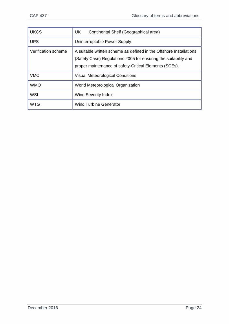
UKCS UK Continental Shelf (Geographical area)
UPS Uninterruptable Power Supply
Verification scheme A suitable written scheme as defined in the Offshore Installations
(Safety Case) Regulations 2005 for ensuring the suitability and
proper maintenance of safety-Critical Elements (SCEs).
VMC Visual Meteorological Conditions
WMO World Meteorological Organization
WSI Wind Severity Index
WTG Wind Turbine Generator
CAP 437 Chapter 1: Introduction
December 2016 Page 25
Chapter 1
Introduction
History of development of criteria for offshore helicopter landing areas, 1964-1973
1.1 In the early 1960s it became apparent that there would be a continuing
requirement for helicopter operations to take place on fixed and mobile
offshore installations. Various ideas were put forward by oil companies
and helicopter operators as to the appropriate landing area standards for
such operations. In 1964, draft criteria were published which used
helicopter rotor diameter as a determinant of landing area size and
associated obstacle-free area. In the light of experience and after further
discussions, the criteria were amended and re-published in 1968. These
criteria were then, and still are, based upon helicopter overall length (from
the most forward position of main rotor tip to the most rearward position of
tail rotor tip plane path, or rearmost extension of the fuselage in the case
of fenestron or Notar tails). This length is commonly referred to as ‘D’ for
any particular helicopter as the determinant of landing area size,
associated characteristics, and obstacle-protected surfaces.
Department of Energy and the Health and Safety Executive guidance on the design and construction of offshore installations, 1973 onwards
1.2 In the early 1970s, the Department of Energy began the process of
collating guidance standards for the design and construction of
‘installations’ – both fixed and mobile. This led to the promulgation of the
Offshore Installations (Construction and Survey Regulations) 1974, which
were accompanied by an amplifying document entitled ‘Offshore
Installations: Guidance on the design and construction of offshore
installations’ (the 4th Edition Guidance). This guidance included criteria for

CAP 437 Chapter 1: Introduction
December 2016 Page 26
helicopter landing areas which had been slightly amended from those
issued in 1968. During 1976 and 1977, the landing area criteria were
developed even further during a full-scale revision of this document,
following consultations between the CAA, the British Helicopter Advisory
Board and others. This material was eventually published in November
1977 and amended further in 1979. This latter amendment introduced the
marking of the landing area to show the datum from which the obstacle-
free area originated, the boundary of the area, and the maximum overall
length of helicopter for which operations to the particular landing area
were suitable. The first edition of CAP 437 was published in 1981,
amended in 1983 and revised in December 1993 (second edition) and
October 1998 (third edition). Following a further amendment in January
2001, a fourth edition of CAP 437, incorporating the new house style, was
placed on the Publications section of the CAA website at www.caa.co.uk
in September 2002. This was superseded by the fifth edition of CAP 437
in August 2005 and a sixth edition in December 2008. Following two
interim amendments, a seventh edition was published in May 2012 and
updated in February 2013. The major changes incorporated into this latest
eighth edition are summarised in the revision history on page 11.
1.3 In April 1991 the Health and Safety Commission (HSC) and the Health
and Safety Executive (HSE) took over from the Department of Energy the
responsibility for offshore safety regulation. The Offshore Safety Act 1992,
implementing the Cullen recommendations following the Piper Alpha
disaster, transferred power to the HSE on a statutory footing. The HSE
also took over sponsorship of the 4th Edition and Section 55 ‘Helicopter
landing areas’ referring to all installations.
1.4 Since April 1991, the HSE has introduced five sets of modern goal-setting
regulations which contain provisions relating to helicopter movements and
helideck safety on offshore installations. These update and replace the old
prescriptive legislation. The provisions are as follows:

CAP 437 Chapter 1: Introduction
December 2016 Page 27
Regulations Covers
1 The Offshore
Installations
(Safety Case)
Regulations 2005
(SCR) (SI
2005/3117)
These regulations
remain applicable
until the
installation has
transitioned its
safety case to
SCR 2015 as
required by
Regulation 39
and Schedule 14
Regulation 2(1) defines a major accident and this includes the
collision of a helicopter with an installation. Regulation 2(1)
defines safety-critical elements (SCEs) and Regulation 2(5)
refers to a verification scheme for ensuring by means described
in Regulation 2(6) that the SCEs will be suitable and remain in
good repair and condition. Helidecks and their associated
systems are deemed to be SCEs. Regulation 6 requires the
submission of a design notification containing the particulars
specified in Schedule 1. Regulation 12(1) requires that a safety
case should demonstrate: the adequacy of the safety
management system to ensure compliance with relevant
statutory provisions; the adequacy of arrangements for audit; that
all hazards with the potential to cause a major accident have
been identified and evaluated; and that measures have been
taken to ensure that the relevant statutory provisions will be
complied with.
2 The Offshore
Installations
(Offshore Safety
Directive)(Safety
Case etc)
Regulations 2015
(SCR 2015)
Regulation 2 defines a major accident and this includes an event
involving a fire, explosion… causing, or with a significant potential
to cause death or serious personal injury to persons on the
installation or engaged in an activity on or in connection with it. It
also is defined as an event involving major damage to the
structure of the installation or plant affixed to it. Although the
specific SCR 2005 reference to helicopter collision has been
removed, both of these SCR 2015 definitions are taken to include
helicopter collision. Regulation 2 defines safety and environment
-critical elements (SECEs) and Regulations 9 and 10 refer to a
verification scheme for ensuring that the SECEs will be suitable
and remain in good repair and condition. Helidecks and their
associated systems are deemed to be SECEs. Regulations 15
and 19 require the submission of a design notification containing
the particulars specified in Schedule 5. Regulation 16(1)
requires that a safety case should demonstrate: the adequacy of
the safety management system to ensure compliance with

CAP 437 Chapter 1: Introduction
December 2016 Page 28
relevant statutory provisions; the adequacy of arrangements for
audit; that all major accident risks have been identified and
evaluated; and that suitable measures will be taken to control
those risks and to ensure that the relevant statutory provisions
will be complied with.
3 The Offshore
Installations
(Prevention of
Fire and
Explosion, and
Emergency
Response)
Regulations 1995
(PFEER)
(SI 1995/743)
Regulation 6(1)(c) requires a sufficient number of personnel
trained to deal with helicopter emergencies to be available during
helicopter movements. Regulation 7 requires the operator/owner
of a fixed/mobile installation to ensure that equipment necessary
for use in the event of an accident involving a helicopter is kept
available near the helicopter landing area. Equipment provided
under Regulation 7 must comply with the suitability and
condition requirements of Regulation 19(1) of PFEER.
Regulations 9, 12 and 13 make general requirements for the
prevention of fire and explosion, the control of fire and explosion
which would take in helicopter accidents. Regulation 17 of
PFEER requires arrangements to be made for the rescue of
people near the installation from helicopter ditchings.
4 The Offshore
Installations and
Pipeline Works
(Management
and
Administration)
Regulations 1995
(MAR) (SI
1995/738)
Regulation 8 requires people to co-operate with the Helicopter
Landing Officer to enable him to perform his function referred to
in Regulation 13. Regulation 11 requires comprehensible
instructions to be put in writing and brought to the attention of
everybody to whom they relate. Circumstances where written
instructions might be needed include helideck operations
(particularly if involving part-time helideck crew). Regulation
12(b) requires arrangements which are appropriate for health and
safety purposes to be in place for effective communication
between an installation, the shore, aircraft and other installations.
Arrangements must also be in place for effective communication
where a helicopter is to land on or take off from an installation
aboard which there will be no person immediately before landing
or after the take-off, and between the helicopter and a suitable
offshore installation with persons on board or, where there is no
suitable installation, suitable premises ashore. Regulation 13
requires the operator/owner of a fixed/mobile installation to

CAP 437 Chapter 1: Introduction
December 2016 Page 29
ensure that a competent person is appointed to be in control of
helideck operations on the installation (i.e. the Helicopter Landing
Officer (HLO)), is present on the installation and is in control
throughout such operations, and procedures are established and
plant provided as will secure so far as is reasonably practicable
that helideck operations including landing/take-off are without
risks to health and safety. Regulation 14 requires the duty holder
to make arrangements for the collection and keeping of
meteorological and oceanographic information and information
relating to the movement of the offshore installation. This is
because environmental conditions may affect helicopter
operations and the ability to implement emergency plans.
Regulation 19 requires the operator/owner of an offshore
installation to ensure that the installation displayed its name in
such a manner as to make the installation readily identifiable by
sea or air; and displays no name, letters or figures likely to be
confused with the name or other designation of another offshore
installation.
5 The Offshore
Installations and
Wells (Design
and Construction,
etc.) Regulations
1996 (DCR) (SI
1996/913)
Regulation 11 – Helicopter Landing Area requires the
operator/owner of a fixed/mobile installation to ensure that every
landing area forming part of an installation is large enough, and
has sufficient clear approach/departure paths, to enable any
helicopter intended to use the landing area safely to land and
take off in any wind and weather conditions permitting helicopter
operations, and is of a design and construction adequate for its
purpose.
The HSE has published guidance documents on SCR, SCR 2015, MAR and DCR and, in
the case of PFEER, combined guidance and an Approved Code of Practice.
1.5 In February 2005 UKOOA (now OGUK) published “Guidelines for the
Management of Offshore Helideck Operations” (Issue 5) preceded in 2004
by an HSE publication ”Offshore Helideck Design Guidelines” which was
sponsored by the HSE and the CAA, and endorsed by the Offshore
Industry Advisory Committee – Helicopter Liaison Group (OIAC-HLG).
The UKOOA ‘Guidelines’ have now been superseded by the Oil and Gas
CAP 437 Chapter 1: Introduction
December 2016 Page 30
UK “Guidelines for the Management of Aviation Operations” (Issue 6, April
2011) which are in the process of being updated. The "Offshore Helideck
Design Guidelines” have been withdrawn by the HSE and the OIAC has
been replaced by OMAHAC (Offshore Major Accident Hazard Advisory
Committee) but with no dedicated Helicopter Liason Group attached.
Applicability of standards in other cases
1.6 For vessels engaged in supporting mineral exploitation (such as crane or
derrick barges, pipe-laying vessels, diving support vessels, seismic
research vessels, etc.), which are not classed as ‘offshore installations’
and so are not subject to a verification scheme, the CAA recommends the
application of the Chapter 9 standards for helicopter landing areas as
contained in this CAP. Compliance with this recommendation will enable
helicopter operators to fulfil their own legal obligations and responsibilities.
1.7 On other merchant vessels where it is impracticable for these standards to
be achieved, for example where the landing area has to be located
amidships or is non-purpose-built on a ship’s side, further criteria to be
used are included in Chapter 9 of this publication. Criteria for helicopter
winching areas on ships and on renewable energy wind turbines are
presented in Chapter 10. For heli-hoist operations, whether to shipboard
winching areas or at wind turbines, specific operational guidance should
be obtained from the helicopter operator or, where a query has to do with
the design of the winching area, from the agency responsible for
certification of the winching area.
Worldwide application
1.8 It should be noted that references are made to United Kingdom legislative
and advisory bodies. However, this document is written so that it may
provide minimum standards applicable for the safe operation of
helicopters to offshore helidecks throughout the world.
1.9 CAP 437 is therefore particularly relevant to UK (G) registered helicopters
operating within and outside the UKCS areas; whether or not they have

CAP 437 Chapter 1: Introduction
December 2016 Page 31
access to the UK authorisation process. In cases where the UK
authorisation process is not applicable or available, helicopter operators
should have in place a system for assessing and authorising the
operational use of each helideck. Within Europe, through the European
Aviation Safety Agency (EASA) Requirements for Air Operators,
Operational Requirements Part-OPS, Annex VI Part SPA, authorisation of
each helicopter landing area is a specific requirement laid down in Part
HOFO (Helicopter Offshore Operations) with guidance on the criteria for
use of offshore locations given in an ‘acceptable means of compliance’
(AMC) (AMC1 SPA.HOFO.115 'Use of offshore locations' which is
reproduced in CAP 437, Appendix A). Throughout the range of operations
covered by Part-SPA.HOFO, agreement has been made to share all
helideck information between helicopter operators by the fastest possible
means. An example of a typical template is shown in Figure 1 of GM1
SPA.HOFO.115.
1.10 Other helicopter operators, who operate outside the areas covered by
EASA Requirements for Air Operators and who are using this document,
are recommended to establish a system for assessing and authorising
each helideck for operational use. It is a fact that many installations and
vessels do not fully comply with the criteria contained in the following
chapters. A system for the assessment of the level of compliance, with
processes and procedures for the management of rectification actions
(where practicable) plus a system for imposing compensating operational
limitations (where rectification actions are impractical), is often the only
fail-safe way of ensuring that the level of safety to flights is not
compromised.

CAP 437 Chapter 2: Helicopter performance considerations
December 2016 Page 32
Chapter 2
Helicopter performance considerations
General considerations
2.1 The criteria for helicopter landing areas on offshore installations and
vessels result from the need to ensure that UK registered helicopters are
afforded sufficient space to be able to operate safely at all times in the
varying conditions experienced offshore.
2.2 The helicopter’s performance requirements and handling techniques are
contained in the Rotorcraft Flight Manual and/or the operator’s Operations
Manual.
2.3 Helicopter companies operating for public transport are required to hold
an AOC which is neither granted nor allowed to remain in force unless
they provide procedures for helicopter crews which safely combine the
space and performance requirements mentioned above.
Safety philosophy
2.4 Aircraft performance data is scheduled in the Flight Manual and/or the
Operations Manual which enables flight crew to accommodate the varying
ambient conditions and operate in such a way that the helicopter has
sufficient space and sufficient engine performance to approach, land on
and take off from helidecks in safety.
2.5 Additionally, Operations Manuals recognise the remote possibility of a
single engine failure in flight and state the flying procedures and
performance criteria which are designed to minimise the exposure time of
the aircraft and its occupants during the short critical periods during the
initial stage of take-off, or final stage of landing.
CAP 437 Chapter 2: Helicopter performance considerations
December 2016 Page 33
Factors affecting performance capability
2.6 On any given day helicopter performance is a function of many factors
including the actual all-up mass; ambient temperature; pressure altitude;
effective wind speed component; and operating technique. Other factors,
concerning the physical and airflow characteristics of the helideck and
associated or adjacent structures, will also combine to affect the length of
the exposure period referred to in paragraph 2.5. These factors are taken
into account in the determination of specific and general limitations which
may be imposed in order to ensure adequate performance and to ensure
that the exposure period is kept to a minimum. In many circumstances the
period will be zero. It should be noted that, following a rare power unit
failure, it may be necessary for the helicopter to descend below deck level
to gain sufficient speed to safely fly away, or in extremely rare
circumstances to land on the water. In certain circumstances, where
exposure periods would otherwise be unacceptably long, it will probably
be necessary to reduce helicopter mass (and therefore payload) or even
to suspend flying operations.

CAP 437 Chapter 3: Helicopter landing areas – Physical characteristics
December 2016 Page 34
Chapter 3
Helicopter landing areas – Physical characteristics
General
3.1 This chapter provides criteria on the physical characteristics of helicopter
landing areas (helidecks) on offshore installations and some vessels.
Where a scheme of verification is required it should state for each
helicopter landing area the maximum size (overall length) of the helicopter
authorised to use the landing area expressed in terms of D-value and the
maximum allowable take-off mass (MTOM) of the helicopter for which that
area is being authorised with regard to its structural limitations, expressed
as a 't' value. Where criteria cannot be met in full for a particular type of
helicopter it may be necessary to promulgate operational restrictions in
order to compensate for deviations from these criteria. The helicopter
operators are notified of any restrictions through the Helideck Limitations
List (HLL).
3.2 The criteria which follow are based on helicopter overall length and mass.
This data is summarised in Table 1 below.
Table 1: D-value, 't' value and other helicopter type criteria
Type
D-
value
(m)
Perimeter
‘D’
marking
Rotor
diameter
(m)
Max
weight
(kg)
‘t’
value Landing net size
Bolkow Bo 105D 12.00 12 9.90 2400 2.4 Not recommended
EC 135 T2+ 12.20 12 10.20 2910 2.9 Not recommended
Bolkow 117 13.00 13 11.00 3200 3.2 Not recommended
Agusta A109 13.05 13 11.00 2600 2.6 Small

CAP 437 Chapter 3: Helicopter landing areas – Physical characteristics
December 2016 Page 35
Dauphin AS365
N2 13.68 14 11.93 4250 4.3 Small
Dauphin AS365
N3 13.73 14 11.94 4300 4.3 Small
EC 155B1 14.30 14 12.60 4850 4.9 Medium
Sikorsky S76 16.00 16 13.40 5307 5.3 Medium
Agusta/Westland
AW 139 16.63 17 13.80 6800 6.8 Medium
Agusta/Westland
AW 189
17.60 18 14.60 8600 8.6t Medium
Airbus H175 18.06 18 14.80 7500 7.5 Medium
Super Puma
AS332L
18.70 19 15.60 8599 8.6t Medium
Bell 214ST 18.95 19 15.85 7938 7.9t Medium
Super Puma
AS332L2
19.50 20 16.20 9300 9.3t Medium
EC 225 (H225) 19.50 20 16.20 11000 11.0t Medium
Sikorsky S92A 20.88 21 17.17 12565 12.6t Large
Sikorsky S61N 22.20 22 18.90 9298 9.3t Large
AW101 22.80 23 18.90 14600 14.6t Large
NOTE: Where skid-fitted helicopters and/or a deck integrated fire fighting system
(DIFFS) are in use landing nets should not be fitted.
Helideck design considerations – Environmental effects
Introduction
3.3 The safety of helicopter flight operations can be seriously degraded by
environmental effects that may be present around installations or vessels
and their helidecks. The term “environmental effects” is used here to
represent the effects of the installation or vessel and/or its systems and/or
processes on the surrounding environment, which result in a degraded
local environment in which the helicopter is expected to operate. These
CAP 437 Chapter 3: Helicopter landing areas – Physical characteristics
December 2016 Page 36
environmental effects are typified by structure-induced turbulence,
turbulence and thermal effects caused by gas turbine exhausts, thermal
effects of flares and diesel exhaust emissions, and unburnt hydrocarbon
gas emissions from cold flaring or, more particularly, emergency blow-
down systems. It is almost inevitable that helidecks installed on the
cramped topsides of offshore installations will suffer to some degree from
one or more of these environmental effects, and controls in the form of
operational restrictions may be necessary in some cases. Such
restrictions can be minimised by careful attention to the design and layout
of the installation topsides and, in particular, the location of the helideck.
3.4 Advice on the design and placement of offshore helidecks is provided in
this document, and includes certain environmental criteria (see paragraph
3.8). These criteria have been set to define safe operating boundaries for
helicopters in the presence of known environmental hazards. Where these
criteria cannot be met, a limitation is placed in the HLL. These entries are
usually specific to particular combinations of wind speed and direction,
and either restrict helicopter mass (payload), or prevent flying altogether
in certain conditions.
3.5 The HLL system is operated for the benefit of the offshore helicopter
operators and should ensure that landings on offshore helidecks are
properly controlled when adverse environmental effects are present. On
poorly designed helidecks, severe operational restrictions may result,
leading to significant commercial penalties for an installation operator or
vessel owner. Well designed and ‘helicopter friendly’ platform topsides
and helidecks should result in efficient operations and cost savings for the
installation operator.
NOTE: It is important that the helicopter operators through the agency responsible for
the certification of the helideck are always consulted at the earliest stage of
design to enable them to provide advice and information so that the process for
authorising the use of the helideck can be completed in a timely fashion and in a
manner which ensures that maximum helicopter operational flexibility is realised.
Information from helideck flow assessment studies (see paragraphs 3.9 and
CAP 437 Chapter 3: Helicopter landing areas – Physical characteristics
December 2016 Page 37
3.10) should be made available to the helicopter operators as early as possible
to enable them to identify any potential adverse environmental effects that may
impinge on helicopter flight operations and which, if not addressed at the design
stage, could lead to operational limitations being imposed to ensure that safety is
not compromised.
Helideck design guidance
3.6 A review of offshore helideck environmental issues (see CAA Paper
99004) concluded that many of the decisions leading to poor helideck
operability had been made in the very early stages of design, and
recommended that it would be easier for designers to avoid these pitfalls if
comprehensive helideck design guidance was made available to run in
parallel with CAP 437. As part of the subsequent research programme,
material covering environmental effects on offshore helideck operations
was commissioned by the HSE and the CAA. This material is now
presented in CAA Paper 2008/03: “Helideck Design Considerations –
Environmental Effects” and is available on the Publications section of the
CAA website at www.caa.co.uk/ publications. It is strongly recommended
that platform designers and offshore duty holders consult CAA Paper
2008/03 at the earliest possible stage of the design process.
3.7 The objective of CAA Paper 2008/03 is to help platform designers to
create offshore installation topside designs and helideck locations that are
safe and ‘friendly’ to helicopter operations by minimising exposure to
environmental effects. It is hoped that, if used from ‘day one’ of the
offshore installation design process when facilities are first being laid out,
this manual will prevent or minimise many helideck environmental
problems at little or no extra cost to the design or construction of the
installation. See also HSE Offshore Information sheet (OIS) No. 5/2011,
issued June 2011.
Design criteria
3.8 The design criteria given in the following paragraphs represent the current
best information available and should be applied to new installations, to

CAP 437 Chapter 3: Helicopter landing areas – Physical characteristics
December 2016 Page 38
significant modifications to existing installations, and to combined
operations (where a mobile platform or vessel is operating in close
proximity to another installation). In the case of multiple platform
configurations, the design criteria should be applied to the arrangement as
a whole.
NOTE: When considering the volume of airspace to which the following criteria apply,
installation designers should consider the airspace up to a height above helideck
level which takes into consideration the requirement to accommodate helicopter
landing and take-off decision points or committal points. This is deemed to be up
to a height above the helideck corresponding to 30 ft plus wheels-to-rotor height
plus one rotor diameter.
3.9 All new-build offshore helidecks, modifications to existing topside
arrangements which could potentially have an effect on the environmental
conditions around an existing helideck, or helidecks where operational
experience has highlighted potential airflow problems should be subject to
appropriate wind tunnel testing or Computational Fluid Dynamics (CFD)
studies to establish the wind environment in which helicopters will be
expected to operate. As a general rule, a limit on the standard deviation of
the vertical airflow velocity of 1.75 m/s should not be exceeded. The
helicopter operator should be informed at the earliest opportunity of any
wind conditions for which this criterion is not met. Operational restrictions
may be necessary.
NOTE 1: Following completion of the validation exercise, the provisional limit on the
standard deviation of the vertical airflow velocity of 2.4 m/s specified in CAP 437
fifth edition was lowered to a threshold advisory limit of 1.75 m/s. This change
was made to allow for flight in reduced cueing conditions, for the less able or
experienced pilot, and to better align the associated measure of pilot workload
with operational experience. However, it was known at the time that the lower
criterion is close to onshore background turbulence levels, and that it would be
unusual for a helideck not to exceed the lower threshold limit for at least some
wind speeds and directions. In consideration of this the lower threshold limit of
1.75 m/s is intended to draw attention to conditions that might result in operating
difficulties and to alert pilots to exercise caution, unless, or until, operating
CAP 437 Chapter 3: Helicopter landing areas – Physical characteristics
December 2016 Page 39
experience has confirmed the airflow characteristics to be acceptable. Therefore
the lower limit functions as the baseline which may be refined in light of in-
service experience. Conversely if the airflow significantly exceeds the upper
criterion of 2.4 m/s it may be advisable to consider modifications to the helideck
to improve airflow (such as by increasing the air-gap), if operating restrictions are
to be avoided. It is recommended that use is made of the helicopter operators’
existing operations monitoring programmes to include the routine monitoring of
pilot workload and that this be used to continuously inform and enhance the
quality of the HLL entries for each platform (see CAA Paper 2008/02 – Validation
of the Helicopter Turbulence Criterion for Operations to Offshore Platforms).
NOTE 2: Following the establishment of the new turbulence criterion for helicopters
operating to offshore installations, the need for retention of the long-standing
CAP 437 criterion related to a vertical wind component of 0.9 m/s has been
reviewed. As it has not been possible to link the criterion to any helicopter
performance (i.e. torque related) or handling (pilot work related) hazard, it is
considered that the vertical mean wind speed criterion can be removed from
CAP 437. The basis for the removal from CAP 437 is described in detail in CAA
Paper 2008/02 Study II – A Review of 0.9 m/s Vertical Wind Component
Criterion for Helicopters Operating to Offshore Installations.
3.10 Unless there are no significant heat sources on the installation or vessel,
offshore duty holders should commission a survey of ambient temperature
rise based on a Gaussian dispersion model and supported by wind tunnel
tests or CFD studies for new-build helidecks, for significant modifications
to existing topside arrangements, or for helidecks where operational
experience has highlighted potential thermal problems. When the results
of such modelling and/or testing indicate that there may be a rise of air
temperature of more than 2°C (averaged over a three-second time
interval), the helicopter operator should be consulted at the earliest
opportunity so that appropriate operational restrictions may be applied.
3.11 Previous editions of CAP 437 have suggested that ‘some form of exhaust
plume indication should be provided for use during helicopter operations,
for example, by the production of coloured smoke’. Research has been
conducted into the visualisation of gas turbine exhaust plumes and

CAP 437 Chapter 3: Helicopter landing areas – Physical characteristics
December 2016 Page 40
guidance on how this can be achieved in practice has been established.
This work is now reported in CAA Paper 2007/02 which recommends that
consideration should be given to installing a gas turbine exhaust plume
visualisation system on platforms having a significant gas turbine exhaust
plume problem in order to highlight the hazards to pilots and thereby
minimising its effects by making it easier to avoid encountering the plume.
It is further recommended that use is made of the helicopter operators’
existing operations monitoring programmes to establish and continuously
monitor the temperature environments around all offshore platforms. This
action is aimed at identifying any ‘problem’ platforms, supporting and
improving the contents of the HLL, identifying any new problems caused
by changes to platform topsides or resulting from combined operations,
and identifying any issues related to flight crew training or procedures.
3.12 The maximum permissible concentration of hydrocarbon gas within the
helicopter operating area is 10% Lower Flammable Limit (LFL).
Concentrations above 10% LFL have the potential to cause helicopter
engines to surge and/or flame out with the consequent risk to the
helicopter and its passengers. It should also be appreciated that, in
forming a potential source of ignition for flammable gas, the helicopter can
pose a risk to the installation itself. It is considered unlikely that routine
‘cold flaring’ will present any significant risk, but the operation of
emergency blow-down systems should be assumed to result in excessive
gas concentrations. Installation operators should have in place a
management system which ensures that all helicopters in the vicinity of
any such releases are immediately advised to stay clear.
NOTE: The installation of ‘Status Lights’ systems (see Chapter 4, paragraph 4.25) is not
considered to be a solution to all potential flight safety issues arising from
hydrocarbon gas emissions; these lights are only a visual warning that the
helideck is in an unsafe condition for helicopter operations.
3.13 For ‘permanent’ multiple platform configurations, usually consisting of two
or more bridge-linked fixed platforms in close proximity, where there is a
physical separation of the helideck from the production and process

CAP 437 Chapter 3: Helicopter landing areas – Physical characteristics
December 2016 Page 41
operation, the environmental effects of hazards emanating from the
‘remote’ production platform should be considered on helideck operations.
This is particularly appropriate for the case of hot or cold gas exhausts
where there will always be a wind direction that carries any exhaust
plumes from a neighbouring platform (bridge-linked module) in the
direction of the helideck.
3.14 For ‘temporary’ combined operations, where one mobile installation or
vessel (e.g. a flotel) is operated in close proximity to a fixed installation,
the environmental effects of hazards emanating from one installation (or
vessel) on the other installation (or vessel) should be fully considered.
This ‘assessment’ should consider the effect of the turbulent wake from
one platform impinging on the helideck of the other, and of any hot or cold
gas exhausts from one installation or vessel influencing the approach to
the other helideck. On occasions there may be more than two installations
and/or vessels in a ‘temporary combined’ arrangement. Where this is the
case, the effect of turbulent wake and hot gas exhausts from each
installation or vessel on all helideck operations within the combined
arrangement should be considered.
NOTE: Paragraphs 3.13 and 3.14 are primarily concerned with the issue of
environmental effects on the helideck design. In respect of permanent multi-
platform configurations and ‘temporary’ combined operations there are a number
of other considerations that may need to be addressed. These include, but may
not be limited to, the effect of temporary combined operations on helideck
obstacle protection criteria. Additional considerations are described in more
detail in Chapter 3 paragraphs 3.31 to 3.33 (Temporary Combined Operations)
and in paragraphs 3.34 to 3.36 (Multiple Platform Configurations).
Structural design
3.15 The take-off and landing area should be designed for the heaviest and
largest helicopter anticipated to use the facility (see Table 1). Helideck
structures should be designed in accordance with relevant International
Organization for Standardization (ISO) codes for offshore structures and
for floating installations. The maximum size and mass of helicopters for
CAP 437 Chapter 3: Helicopter landing areas – Physical characteristics
December 2016 Page 42
which the helideck has been designed should be stated in the Installation
Operations Manual and Verification and/or Classification document. For
structural design requirements for helicopter landing areas located on
vessels (i.e. non-installations), reference may be made to appropriate
Class Society rules.
3.16 Optimal operational flexibility may be gained from considering the
potential life and usage of the facility along with likely future developments
in helicopter design and technology.
3.17 Consideration should also be given in the design to other types of loading
such as personnel, other traffic, snow and ice, freight, refuelling
equipment, rotor downwash etc. as stated in the relevant ISO codes or
Class Society rules. It may be assumed that single main rotor helicopters
will land on the wheel or wheels of two landing gear (or both skids if
fitted). The resulting loads should be distributed between two main
undercarriages. Where advantageous a tyre contact area may be
assumed in accordance with the manufacturer’s specification. Working
stress design or ultimate limit state (ULS) methods may be used for the
design of the helideck structure, including girders, trusses, pillars,
columns, plating and stiffeners. A serviceability limit check should also be
performed to confirm that the maximum deflection of the helideck under
maximum load is within code limits. This check is intended to reduce the
likelihood of the helideck structure being so damaged during an
emergency incident as to prevent other helicopters from landing.
NOTE: Requirements for the structural design of helidecks are comprehensively set out
in ISO 19901-3 Petroleum and natural gas industries – Specific requirements for
offshore structures, Part 3: Topsides structure (first published in December
2010).
3.18 Consideration should be given to the possibility of accommodating an
unserviceable helicopter in a designated parking or run-off area (where
provided) adjacent to the helideck to allow a relief helicopter to land. If this
contingency is designed into the construction/operating philosophy of the

CAP 437 Chapter 3: Helicopter landing areas – Physical characteristics
December 2016 Page 43
installation, the helicopter operator should be advised of any weight
restrictions imposed on the relief helicopter by structural integrity
considerations. Where a parking or run-off area is provided it is assumed
that the structural considerations will at least meet the loads criteria
applicable for helicopters at rest (see paragraph 3.21). Parking areas are
addressed in more detail in paragraphs 3.59 to 3.62.
3.19 Alternative loading criteria equivalent to those recommended here and in
paragraphs 3.20 and 3.21 may be used where aircraft-specific loads have
been derived by the aircraft manufacturer from a suitable engineering
assessment taking account of the full range of potential landing
conditions, including failure of a single engine at a critical point, and the
behaviour of the aircraft undercarriage and the response of the helideck
structure. The aircraft manufacturer should provide information to
interested parties, including the owner or operator of the installation and
the helicopter operators to justify use of alternative criteria. The aircraft
manufacturer may wish to seek the opinion of the CAA on the basis of the
criteria to be used. In consideration of alternative criteria, the CAA is
content to assume that a single engine failure represents the worst case
in terms of rate of descent on to the helideck amongst likely survivable
emergencies.
Loads
Helicopters landing
3.20 The helideck should be designed to withstand all the forces likely to act
when a helicopter lands. The loads and load combinations to be
considered should include:
1) Dynamic load due to impact landing. This should cover both a
heavy normal landing and an emergency landing. For the former, an
impact load of 1.5 x MTOM of the design helicopter should be used,
distributed as described in paragraph 3.17. This should be treated as
an imposed load, applied together with the combined effect of 1) to

CAP 437 Chapter 3: Helicopter landing areas – Physical characteristics
December 2016 Page 44
7) in any position on the landing area so as to produce the most
severe load on each structural element. For an emergency landing,
an impact load of 2.5 x MTOM should be applied in any position on
the landing area together with the combined effects of 2) to 7)
inclusive. Normally, the emergency landing case will govern the
design of the structure.
2) Sympathetic response of landing platform. After considering the
design of the helideck structure’s supporting beams and columns
and the characteristics of the designated helicopter, the dynamic
load (see 1) above) should be increased by a suitable structural
response factor depending upon the natural frequency of the
helideck structure. It is recommended that a structural response
factor of 1.3 should be used unless further information derived from
both the helideck manufacturer and the helicopter manufacturer will
allow a lower factor to be calculated. Information required to do this
will include the natural periods of vibration of the helideck and the
dynamic characteristics of the design helicopter and its landing gear.
3) Overall superimposed load on the landing platform. To allow for
any appendages that may be present on the deck surface (e.g.
helideck net, "H" and circle lighting etc.) in addition to wheel loads,
an allowance of 0.5 kiloNewtons per square metre (kN/m2) should
be added over the whole area of the helideck.
4) Lateral load on landing platform supports. The landing platform
and its supports should be designed to resist concentrated horizontal
imposed loads equivalent to 0.5 x MTOM of the helicopter,
distributed between the undercarriages in proportion to the applied
vertical loading in the direction which will produce the most severe
loading on the element being considered.
5) Dead load of structural members. This is the normal gravity load
on the element being considered.
6) Wind loading. Wind loading should be allowed for in the design of
the platform. The helideck normal restricting wind conditions (i.e. 60
knots equivalent to 31 m/s) should be applied in the direction which,

CAP 437 Chapter 3: Helicopter landing areas – Physical characteristics
December 2016 Page 45
together with the imposed lateral loading, will produce the most
severe loading condition on each structural element.
7) Inertial actions due to platform motions for floating
installations. The effects of accelerations and dynamic amplification
arising from the predicted motions of a floating platform in a storm
condition with a 10-year return period should be considered.
8) Punching shear check (applicable to wooden or concrete
structures). A check should be made for the punching shear from a
wheel of the landing gear with a contact area of 65 x 103 mm2 acting
in any probable location. Particular attention to detailing should be
taken at the junction of the supports and the platform deck.
Helicopters at rest
3.21 The helideck should be designed to withstand all the applied forces that
could result from a helicopter at rest; the following loads should be taken
into account:
1) Imposed load from helicopter at rest. All areas of the helideck
accessible to a helicopter, including any separate parking or run-off
area, should be designed to resist an imposed load equal to the
MTOM of the design helicopter. This load should be distributed
between all the landing gear. It should be applied in any position on
the helideck so as to produce the most severe loading on each
element considered.
2) Overall superimposed load. To allow for personnel, freight,
refuelling equipment and other traffic, snow and ice, rotor downwash
etc., an allowance of 2.0 kiloNewtons per square metre (kN/m2)
should be added to the whole area of the helideck.
3) Dead load and wind load. The values for these loads are the same
as given in paragraph 3.20 5) and 6) and should be considered to
act simultaneously in combination with paragraph 3.21 1) and 2).
Consideration should also be given to the additional wind loading
from any parked or secured helicopter.

CAP 437 Chapter 3: Helicopter landing areas – Physical characteristics
December 2016 Page 46
4) Acceleration forces and other dynamic amplification forces. The
effect of these forces, arising from the predicted motions of mobile
installations and vessels, in the appropriate environmental conditions
corresponding to a 10-year return period, should be considered.
Size and obstacle protected surfaces
NOTE: The location of a specific helideck is often a compromise given the competing
requirements for space. Helidecks should be at or above the highest point of the
main structure. This is a desirable feature but it should be appreciated that if this
entails a landing area much in excess of 60 m above sea level, the regularity of
helicopter operations may be adversely affected in low cloud base conditions.
3.22 For any particular type of single main rotor helicopter, the helideck should
be sufficiently large to contain a circle of diameter D equal to the largest
dimension of the helicopter when the rotors are turning. This D-circle
should be totally unobstructed (see Table 1 for D values). Due to the
actual shape of most offshore helidecks the D-circle will be ‘hypothetical’
but the helideck shape should be capable of accommodating such a circle
within its physical boundaries.
3.23 From any point on the periphery of the above mentioned D-circle an
obstacle-free approach and take-off sector should be provided which
totally encompasses the landing area (and D-circle) and which extends
over a sector of at least 210°. Within this sector obstacle accountability
should be considered out to a distance from the periphery of the landing
area that will allow for an unobstructed departure path appropriate to the
helicopter the helideck is intended to serve. For helicopters operated in
Performance Class 1 or 2 the horizontal extent of this distance from the
helideck will be based upon the one-engine inoperative capability of the
helicopter type to be used. In consideration of the above, only the
following items essential for safe helideck operations may exceed the
height of the landing area, but should not do so by more than 25
centimetres. For new build helidecks completed on or after 10 November
2018 and for refurbishments, the height of essential items around the

CAP 437 Chapter 3: Helicopter landing areas – Physical characteristics
December 2016 Page 47
helideck should not exceed 15 cm for any helideck where the D-value is
greater than 16.01 m. For helidecks, where the D-value is 16.00 m or less
the height of essential items around the helideck should not exceed 5 cm.
Essential items include:
the guttering (associated with the requirements in paragraph 3.44);
the lighting required by Chapter 4;
the foam monitors (where provided); and
those handrails and other items (e.g. EXIT sign) associated with the
landing area which are incapable of complete retraction or lowering
for helicopter operations.
3.24 Objects whose function requires that they be located on the surface of the
helideck such as landing nets, tie-down points, and “circle” and “H”
lighting systems (see Appendix C) should not exceed a height of 25 mm.
Such objects should only be present above the surface of the touchdown
area provided they do not cause a hazard to helicopter operations.
3.25 The bisector of the 210° Obstacle Free Sector (OFS) should normally
pass through the centre of the D-circle. The sector may be ‘swung’ by up
to 15° as illustrated in Figure 1. Acceptance of the ‘swung’ criteria will
normally only be applicable to existing installations.
NOTE: If the 210° OFS is swung, then it would be normal practice to swing the 180°
falling 5:1 gradient by a corresponding amount to indicate, and align with, the
swung OFS.
3.26 The diagram at Figure 1 shows the extent of the two segments of the 150°
Limited Obstacle Sector (LOS) and how these are measured from the
centre of the (hypothetical) D-circle and from the perimeter of the landing
area. This diagram assumes, since most helidecks are designed to the
minimum requirement of accommodating a 1 D-circle, that the D-circle
perimeter and landing area perimeter are coincidental. No objects above
25 cm (or 5 cm where the D-value of the helideck is 16.00 m or less) are
permitted in the first (hatched area in Figure 1) segment of the LOS. The
first segment extends out to 0.62D from the centre of the D-circle, or
CAP 437 Chapter 3: Helicopter landing areas – Physical characteristics
December 2016 Page 48
0.12D from the landing area perimeter marking. The second segment of
the LOS, in which no obstacles are permitted to penetrate, is a rising 1:2
slope originating at a height of 0.05D above the helideck surface and
extending out to 0.83D from the centre of the D-circle (i.e. a further 0.21D
from the edge of the first segment of the LOS).
NOTE: The exact point of origin of the LOS is assumed to be at the periphery of the D-
circle.
3.27 Some helidecks are able to accommodate a landing area which covers a
larger area than the declared D-value; a simple example being a
rectangular deck with the minor dimension able to contain the D-circle. In
such cases it is important to ensure that the origin of the LOS (and OFS)
is at the perimeter of the landing area as marked by the perimeter line.
Any landing area perimeter should guarantee the obstacle protection
afforded by both segments of the LOS. The respective measurements of
0.12D from the landing area perimeter line plus a further 0.21D are to be
applied. On these larger decks there is thus some flexibility in deciding the
position of the perimeter line and landing area in order to meet the LOS
requirements and when considering the position and height of fixed
obstacles. Separating the origin of the LOS from the perimeter of the D-
circle in Figure 1 and moving it to the right of the page will demonstrate
how this might apply on a rectangular-shaped landing area.

CAP 437 Chapter 3: Helicopter landing areas – Physical characteristics
December 2016 Page 49
Figure 1: Obstacle limitation (single main rotor and side by side main rotor helicopters) showing position of touchdown/positioning marking circle
NOTE: Where the D-value is 16.00 m or less, objects in the first segment of the LOS are
restricted to 5 cm.
3.28 The extent of the LOS segments will, in all cases, be lines parallel to the
landing area perimeter line and follow the boundaries of the landing area

CAP 437 Chapter 3: Helicopter landing areas – Physical characteristics
December 2016 Page 50
perimeter (see Figure 1). Only in cases where the perimeter of the landing
area is circular will the extent of the LOS be in the form of arcs to the D-
circle. However, taking the example of an octagonal landing area as
drawn at Figure 1, it would be possible to replace the angled corners of
the two LOS segments with arcs of 0.12D and 0.33D centred on the two
adjacent corners of the landing area, thus cutting off the angled corners of
the LOS segments. If these arcs are applied they should not extend
beyond the two corners of each LOS segment so that minimum
clearances of 0.12D and 0.33D from the corners of the landing area are
maintained. Similar geometric construction may be made to a square or
rectangular landing area but care should be taken to ensure that the LOS
protected surfaces minima can be satisfied from all points on the inboard
perimeter of the landing area.
3.29 For new build helideck designs the minimum landing area size should
accommodate a circle encompassed by the outer edge of perimeter
marking of at least 1D (see paragraph 3.26). However, from time-to-time
new helicopter types may be introduced to the UKCS which were not in
operational use when an existing helideck was designed. In this case
there is a mechanism to review operations by larger (and usually heavier)
helicopters than were specified in the original design for the helideck,
when subject to a thorough risk assessment. The framework for a risk
assessment process for helicopter operations to helidecks on the UKCS,
which are sub-1D, is reproduced at Appendix H and may be used by a
helicopter operator to present a case for sub-1D operations to the CAA.
3.30 Whilst application of the criteria in paragraph 3.23 will ensure that no
unacceptable obstructions exist above the helicopter landing area level
over the whole 210° sector, it is necessary to consider the possibility of
helicopter loss of height due to a power unit failure during the latter stages
of the approach or early stages of take-off. Accordingly, a clear zone
should be provided below landing area level on all fixed and mobile
installations between the helideck and the sea. The falling 5:1 gradient
should be at least 180° with an origin at the centre of the D-circle and

CAP 437 Chapter 3: Helicopter landing areas – Physical characteristics
December 2016 Page 51
ideally it should cover the whole of the 210° OFS. It should extend
outwards for a distance that will allow for safe clearance from obstacles
below the helideck in the event of an engine failure for the type of
helicopter the helideck is intended to serve. (See also Glossary of Terms
and Abbreviations.) For helicopters operated in Performance Class 1 or 2
the horizontal extent of this distance from the helideck will be based upon
the one-engine inoperative capability of the helicopter type to be used
(see Figure 2). All objects that are underneath anticipated final approach
and take-off paths should be assessed.
NOTE 1: For practical purposes the falling obstacle limitation surface can be assumed to
be defined from points on the outboard edge of the helideck perimeter safety
netting supports (not less than 1.5 metres from deck edge). Minor infringements
of the surface by foam monitor platforms or access/escape routes may be
accepted only if they are essential to the safe operation of the helideck but may
also attract helicopter operational limitations.
NOTE 2: Research completed in 1999 (see Appendix B references) demonstrated that,
following a single engine failure in a twin engine helicopter after take-off decision
point, and assuming avoidance of the deck edge, the resulting trajectory will
carry the helicopter clear of any obstruction in the range 2:1 to 3:1. It is therefore
only necessary for operators to account for performance in relation to specified
5:1 falling gradient when infringements occur to a falling 3:1 rather than a 5:1
slope.

CAP 437 Chapter 3: Helicopter landing areas – Physical characteristics
December 2016 Page 52
Figure 2: Obstacle free areas - Below landing area level (for all types of helicopters)
Temporary combined operations
3.31 Temporary Combined Operations are essentially arrangements where two
or more offshore installations, whether fixed or floating, are in close
proximity ‘alongside’ or ‘pulled away’ from one another. They may be in
place for a matter of hours, days, months or for up to several years. On

CAP 437 Chapter 3: Helicopter landing areas – Physical characteristics
December 2016 Page 53
occasions, combined operations may include vessels working alongside
one or more fixed and/or floating installations. The close proximity of
installations and/or vessels one to another is likely to entail that one or
more of the landing areas becomes operationally restricted due to
obstacle protected surfaces being compromised and/or due to adverse
environmental effects.
3.32 So, for example, the installation pictured in the centre of Figure 3 has
obstacle protected sectors and surfaces (the extended OFSs as well as
the falling gradient) that are severely compromised by the proximity of the
other two installations. In these circumstances a landing prohibited marker
(a yellow cross on a red background) is placed on the drilling facility
(centre) to prevent operations to the helideck. Where temporary combined
operations are planned, a helicopter operator assessment should be
completed to review the physical, as well as the environmental, impact of
the arrangements and to assess whether any flight restrictions or
limitations, including prohibitions, should be disseminated to air crews. All
helicopter landing areas which are determined to be ‘unavailable’ should
display the relevant landing prohibited marker by day while, by day and
night, the perimeter lights should be displayed but all other helideck
lighting systems (circle/H lighting and/or helideck floodlights) should be
extinguished.
3.33 Combined operations usually involve both installations and/or vessels
being in close proximity ‘alongside’ one another (as pictured), where the
effect of one facility on the obstacle protected surfaces of another is
immediately obvious. However, during the life of a combined arrangement
there may also be periods when mobile installations and/or vessels are
‘pulled-away’ to a stand-off position, which could entail them being some
distance apart. It is necessary for helicopter operators to re-appraise the
situation for combined operations now in the ‘stand-off’ configuration as
with one or more installations or vessels ‘pulled-away’ there may then be
opportunity to relax or remove limitations otherwise imposed for the
‘alongside’ configuration.
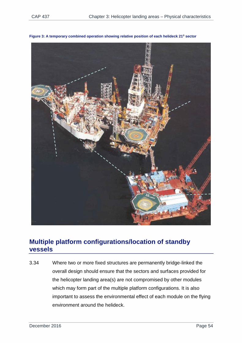
CAP 437 Chapter 3: Helicopter landing areas – Physical characteristics
December 2016 Page 54
Figure 3: A temporary combined operation showing relative position of each helideck 210 sector
Multiple platform configurations/location of standby vessels
3.34 Where two or more fixed structures are permanently bridge-linked the
overall design should ensure that the sectors and surfaces provided for
the helicopter landing area(s) are not compromised by other modules
which may form part of the multiple platform configurations. It is also
important to assess the environmental effect of each module on the flying
environment around the helideck.
CAP 437 Chapter 3: Helicopter landing areas – Physical characteristics
December 2016 Page 55
3.35 Where there is an intention to add new modules to an existing platform
arrangement it is important to make an assessment on the potential
impact that additional modules may have on helideck operations. This will
include an assessment of the sectors and surfaces for the helideck which
should not be compromised due to the location of a new module, or
modification to an existing module. This will include a detailed analysis of
the environmental impact on the flying environment around the helideck
(e.g. using CFD).
3.36 Where there is a requirement to position, at sea surface level, offshore
support vessels (e.g. a Standby Vessel or tanker) essential to the
operation of a fixed or floating offshore installation located within the
proximity of the fixed or floating installation’s obstacle free sector (OFS),
but below helideck level, care should be taken to ensure offshore support
vessels are not positioned to compromise the safety of helicopter
operations during take-off, departure and approach to landing.
Surface
NOTE: Where a helideck is constructed in the form of a grating, e.g. where a passive fire
retarding system is selected (see Chapter 5), the design of the helideck should
ensure that ground effect is not reduced.
3.37 The landing area should present a non-slip surface for helicopter
operations. The installation operator should ensure that the helideck is
kept free from oil, grease, ice, snow, excessive surface water or any other
contaminant (particularly guano) that could degrade the surface friction.
Assurance should be provided to the helicopter operator that procedures
are in place for elimination and removal of contaminants prior to helicopter
movements.
3.38 The minimum average surface friction values that should be achieved are
detailed in Table 2. The average surface friction values should be
confirmed using a test method acceptable to the CAA – see paragraphs
3.39, 3.40 and 3.41.

CAP 437 Chapter 3: Helicopter landing areas – Physical characteristics
December 2016 Page 56
Table 2: Friction requirements
Section of helideck Fixed helideck Moving helideck
Inside TD/PM circle 0.6 0.65
TD/PM circle and H painted markings 0.6 0.65
Outside TD/PM circle 0.5 0.5
3.39 For flat helidecks with a micro-texture finish (e.g. non-slip paint or grit-
blasted finish), the helideck friction test method should normally comprise
the following:
a survey of the entire helideck surface in two orthogonal directions to
a resolution of not less than 1 m2;
use of a tester employing the braked wheel technique and a tyre
made of the same material as helicopter tyres;
testing in the wet condition using a tester that is capable of
controlling the wetness of the deck during testing, and
use of a tester which provides electronic data collection, storage and
processing.
An example test protocol based on the use of the Findlay Irvine MicroGT
is presented in Appendix K.
NOTE 1: No two adjacent 1 m squares should achieve less than the average surface
friction value specified in paragraph 3.38 above.
NOTE 2: Where TD/PM circle and ‘H’ lighting is installed, testing of the TD/PM circle and
‘H’ painted markings is not required.
3.40 The helideck should be re-tested annually or when the condition of the
deck suggests more frequent testing is appropriate, e.g. build-up of guano
or other contaminant(s).
3.41 For profiled helideck surfaces, typically constructed from extruded
aluminium planks, a specimen should be submitted to a suitably qualified
and independent test facility for testing at full scale. The testing should
normally comprise the following:

CAP 437 Chapter 3: Helicopter landing areas – Physical characteristics
December 2016 Page 57
use of a representative helicopter wheel and tyre with a tyre contact
area of at least 200 cm2;
testing at a vertical load to produce a tyre contact pressure of at
least 0.95 N/mm2 and ideally 1 N/mm2, and also within the normal
range of loads and tyre pressures for the aircraft wheel being used
for the testing;
testing in the wet condition;
testing in all four permutations of wheel and surface profiling
directions, i.e. wheel in rolling (R) and non-rolling (N) directions,
along, i.e. longitudinal (L), and across, i.e. transverse (T), the ridges
of the profiling to give the four test conditions of RL, RT, NL and NT;
at least three test runs to be performed for each test condition;
the result for each test run should be the average surface friction
value for the run, excluding the initial peak due to static friction;
the result for each test condition should be the average of the (at
least three) test runs for that condition;
the overall result for the helideck specimen should be the lowest of
the results for the four conditions.
NOTE 1: Each test run may be performed using a ‘fresh’, undamaged section of the test
tyre.
NOTE 2: For the area outside the TD/PM Circle, an inadequate surface friction value (i.e.
< 0.5) may be rectified by grit blasting or by applying a suitable non-slip paint
coating. For the area inside the TD/PM Circle (< 0.6 for fixed helidecks, < 0.65
for moving helidecks), removal of the profiling prior to grit blasting or painting is
recommended or, alternatively, the fitment of a helideck net – see paragraph
3.42 below.
NOTE 3: The testing described in this paragraph represents a once-off type approval and
no further in-service monitoring or testing is required unless the helideck has to
be provided with a micro-texture finish in order to meet the minimum surface
friction values required. In that case, the in-service monitoring/testing protocol
specified in paragraph 3.39 should be applied with the friction tester to be used
being calibrated using the full scale test results. The calibration should comprise
multiplying the friction tester readings using the following scaling factor:

CAP 437 Chapter 3: Helicopter landing areas – Physical characteristics
December 2016 Page 58
𝑆𝑐𝑎𝑙𝑖𝑛𝑔 𝑓𝑎𝑐𝑡𝑜𝑟 = 𝑠𝑢𝑚 𝑜𝑓 𝑅𝐿 + 𝑅𝑇 𝑡𝑒𝑠𝑡 𝑐𝑜𝑛𝑑𝑖𝑡𝑖𝑜𝑛 𝑓𝑢𝑙𝑙 𝑠𝑐𝑎𝑙𝑒 𝑟𝑒𝑠𝑢𝑙𝑡𝑠
𝑠𝑢𝑚 𝑜𝑓 𝐿 + 𝑇 𝑎𝑣𝑒𝑟𝑎𝑔𝑒 𝑓𝑟𝑖𝑐𝑡𝑖𝑜𝑛 𝑡𝑒𝑠𝑡𝑒𝑟 𝑟𝑒𝑠𝑢𝑙𝑡𝑠
NOTE 4: Providing a lasting non-slip paint finish to the tops of ribs can be challenging. Grit
blasted micro-texture finishes are likely to be more effective and more durable
than non-slip paint finishes on profiled helideck surfaces.
3.42 For the area that encompasses the TD/PM Circle only, a helideck net may
be used to mitigate for insufficient surface friction provided that the
average surface friction value is at least 0.5. The net should be installed
and tensioned in accordance with the manufacturer’s instructions and
should have the following properties:
the mesh size should be such as to present an area of between 400
and 900 cm2;
the net should be secured at intervals approximately 1.5 metres
between the lashing points around the landing area perimeter;
the breaking strain of the rope/webbing from which the net is
constructed and the load capacity of the net anchoring points should
be at least 10 kN;
the size of the net should such as to ensure coverage of the TD/PM
Circle area but should not cover the helideck identification marking
(name) or ‘t’ value markings.
NOTE 1: Helideck nets are incompatible with helicopters fitted with skid undercarriages
and should not be used where the operation of such aircraft is to take place.
NOTE 2: It should be borne in mind when selecting a helideck net that the height of the
netting (i.e. the thickness of the installed net including knots) should be in
accordance with the requirements specified in paragraph 3.23.
NOTE 3: The helideck net may be any shape but should cover the whole of the TD/PM
circle, but not be so large as to obscure other essential markings e.g. helideck
name marking, maximum allowable mass marking. The net should be
constructed from durable materials not prone to flaking due to prolonged
exposure to the weather (e.g. UV light), or to the elements (e.g. salt water).

CAP 437 Chapter 3: Helicopter landing areas – Physical characteristics
December 2016 Page 59
NOTE 4: If a helideck net is to be fitted, measures should be taken to ensure that:
the performance of TD/PM Circle and ‘H’ lighting is not impaired. This will
be especially evident at low angles (i.e. less than 6 degrees) of elevation;
the net does not impair the operation of automatic fire-fighting system ‘pop-
up’ nozzles, where fitted, or otherwise compromise the fire fighting
facilities.
3.43 In addition to paragraph 3.42 above, it will normally be necessary to install
helideck nets on Normally Unattended Installations (NUIs) where it is
impractical to guarantee that the helideck will remain clear of
contaminants such that there is no risk of helideck markings and visual
cues being compromised or friction properties reduced. It is
recommended that the design of new installations should incorporate the
provision of helideck net fittings regardless of the type of friction surface to
be provided.
3.44 Every landing area should be equipped with adequate surface drainage
arrangements and a free-flowing collection system that will quickly and
safely direct any rainwater and/or fuel spillage and/or fire fighting media
away from the helideck surface to a safe place. Helidecks on fixed
installations should be cambered (or laid to a fall) to approximately 1:100.
Any distortion of the helideck surface on an installation due to, for
example, loads from a helicopter at rest should not modify the landing
area drainage system to the extent of allowing spilled fuel to remain on
the deck. A system of guttering on a new-build or a slightly raised kerb
should be provided around the perimeter to prevent spilled fuel from
falling on to other parts of the installation and to conduct the spillage to an
appropriate drainage system. The capacity of the drainage system should
be sufficient to contain the maximum likely spillage of fuel on the helideck.
The calculation of the amount of spillage to be contained should be based
on an analysis of helicopter type, fuel capacity, typical fuel loads and
uplifts. The design of the drainage system should preclude blockage by
debris which is best achieved by use of a mesh type filtration system able

CAP 437 Chapter 3: Helicopter landing areas – Physical characteristics
December 2016 Page 60
to strain out smaller items of debris. The helideck area should be properly
sealed so that spillage will only route into the drainage system.
Helicopter tie-down points
3.45 Sufficient flush fitting (when not in use) tie-down points should be provided
for securing the maximum sized helicopter for which the helideck is
designed. They should be so located and be of such strength and
construction to secure the helicopter when subjected to weather
conditions pertinent to the installation design considerations. They should
also take into account, where significant, the inertial forces resulting from
the movement of floating units.
Figure 4: Example of suitable tie-down configuration
NOTE 1: The tie-down configuration should be based on the centre of the TD/PM Circle.
NOTE 2: Additional tie-downs will be required in a parking area.
NOTE 3: The outer circle is not required for D-values of less than 22.2 m.

CAP 437 Chapter 3: Helicopter landing areas – Physical characteristics
December 2016 Page 61
3.46 Tie-down strops held on the installation or vessel should be compatible
with the bar diameter of the helideck tie-down points. Tie-down points and
strops should be of such strength and construction so as to secure the
helicopter when subjected to weather conditions pertinent to the
installation design considerations. The maximum bar diameter of the tie-
down point should be 22 mm in order to match the strop hook dimension
of typical tie-down strops. Advice on recommended safe working load
requirements for strop/ring arrangements for specific helicopter types can
be obtained from the helicopter operator.
3.47 An example of a suitable tie-down configuration is shown at Figure 4. The
agency responsible for the certification of the helideck should be able to
provide guidance on the configuration of the tie-down points for specific
helicopter types.
Perimeter safety net
3.48 Safety nets for personnel protection should be installed around the
landing area except where adequate structural protection against a fall
exists. The netting used should be of a flexible nature, with the inboard
edge fastened just below the edge of the helicopter landing deck. The net
itself should extend at least 1.5 metres, but no more than 2.0 metres, in
the horizontal plane and be arranged so that the outboard edge does not
exceed the level of the landing area and angled so that it has an upward
and outward slope of approximately 10°.
3.49 A safety net designed to meet these criteria should ‘contain’ personnel
falling into it and not act as a trampoline. Where lateral or longitudinal
centre bars are provided to strengthen the net structure they should be
arranged and constructed to avoid causing serious injury to persons
falling on to them. The ideal design should produce a ‘hammock’ effect
which should securely contain a body falling, rolling or jumping into it,
without serious injury. When considering the securing of the net to the
structure and the materials used, care should be taken that each segment
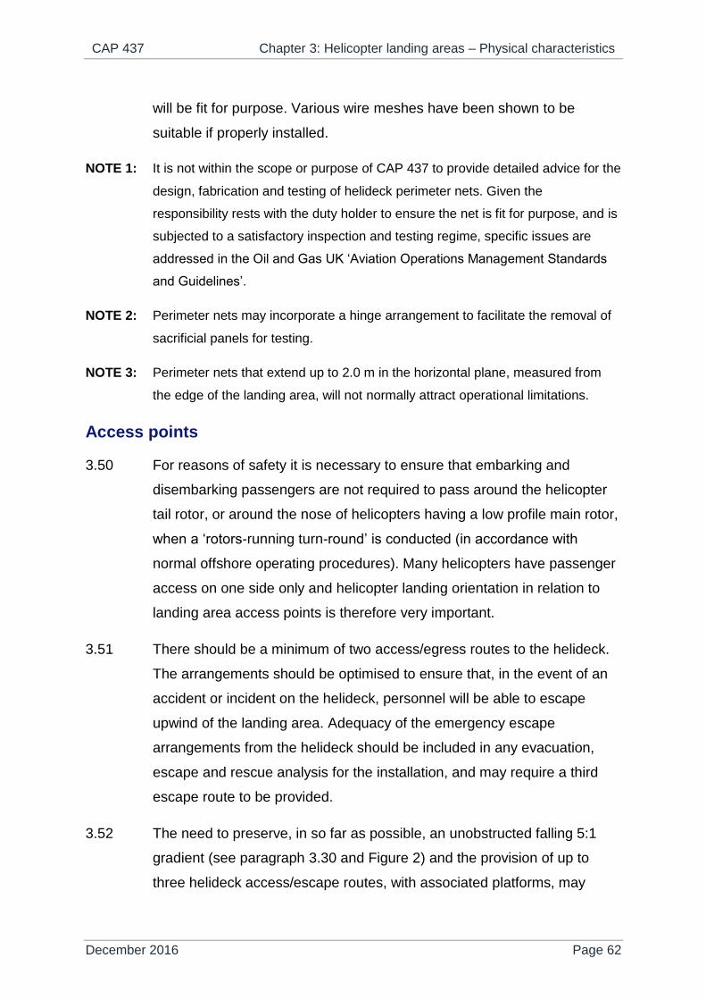
CAP 437 Chapter 3: Helicopter landing areas – Physical characteristics
December 2016 Page 62
will be fit for purpose. Various wire meshes have been shown to be
suitable if properly installed.
NOTE 1: It is not within the scope or purpose of CAP 437 to provide detailed advice for the
design, fabrication and testing of helideck perimeter nets. Given the
responsibility rests with the duty holder to ensure the net is fit for purpose, and is
subjected to a satisfactory inspection and testing regime, specific issues are
addressed in the Oil and Gas UK ‘Aviation Operations Management Standards
and Guidelines’.
NOTE 2: Perimeter nets may incorporate a hinge arrangement to facilitate the removal of
sacrificial panels for testing.
NOTE 3: Perimeter nets that extend up to 2.0 m in the horizontal plane, measured from
the edge of the landing area, will not normally attract operational limitations.
Access points
3.50 For reasons of safety it is necessary to ensure that embarking and
disembarking passengers are not required to pass around the helicopter
tail rotor, or around the nose of helicopters having a low profile main rotor,
when a ‘rotors-running turn-round’ is conducted (in accordance with
normal offshore operating procedures). Many helicopters have passenger
access on one side only and helicopter landing orientation in relation to
landing area access points is therefore very important.
3.51 There should be a minimum of two access/egress routes to the helideck.
The arrangements should be optimised to ensure that, in the event of an
accident or incident on the helideck, personnel will be able to escape
upwind of the landing area. Adequacy of the emergency escape
arrangements from the helideck should be included in any evacuation,
escape and rescue analysis for the installation, and may require a third
escape route to be provided.
3.52 The need to preserve, in so far as possible, an unobstructed falling 5:1
gradient (see paragraph 3.30 and Figure 2) and the provision of up to
three helideck access/escape routes, with associated platforms, may

CAP 437 Chapter 3: Helicopter landing areas – Physical characteristics
December 2016 Page 63
present a conflict of requirements. A compromise may therefore be
required between the size of the platform commensurate with its
effectiveness and the need to retain the protection of an unobstructed
falling 5:1 gradient. In practice, the 5:1 gradient is taken from the outboard
edge of the helideck perimeter safety net supports. Emergency access
points which extend outboard from the perimeter safety net constitute a
compromise in relation to an unobstructed falling 5:1 gradient which may
lead, in some instances, to the imposition of helicopter operating
limitations. It is therefore important to construct access point platforms in
such a manner as to infringe the falling 5:1 gradient by the smallest
possible amount but preferably not at all. Suitable positioning of two major
access points clear of the requirements of the protection of the falling 5:1
gradient should be possible. However, the third access referred to at
paragraph 10.2 will probably lie within the falling 5:1 sector and where this
is the case it should be constructed within the dimensions of the helideck
perimeter safety net supports (i.e. contained within a horizontal distance
of 1.5 - 2.0 m measured from the edge of the landing area).
3.53 Where foam monitors are co-located with access points care should be
taken to ensure that no monitor is so close to an access point as to cause
injury to escaping personnel by operation of the monitor in an emergency
situation.
3.54 Where handrails associated with helideck access/escape points exceed
the height limitations given at paragraph 3.23 they should be retractable,
collapsible or removable. When retracted, collapsed or removed the rails
should not impede access/egress or lead to gaps which could result in a
potential fall from height. Handrails which are retractable, collapsible and
removable should be painted in a contrasting colour scheme. Procedures
should be in place to retract, collapse or remove them prior to helicopter
arrival. Once the helicopter has landed, and the crew have indicated that
passenger movement may commence (see Note below), the handrails
may be raised and locked in position. The handrails should be retracted,
collapsed or removed again prior to the helicopter taking off.

CAP 437 Chapter 3: Helicopter landing areas – Physical characteristics
December 2016 Page 64
NOTE: The helicopter crew will switch off the anti-collision lights to indicate that the
movement of passengers and/or freight may take place (under the control of the
HLO). Installation/vessel safety notices placed on approach to the helideck
access should advise personnel not to approach the helicopter when the anti-
collision lights are on.
Winching (hoist) operations
3.55 Except for operations to Wind Turbine Generators (WTGs) – see Chapter
10, paragraph 10.14 – for any other installation or vessel, attended or
unattended, fixed or mobile for which helicopters are a normal mode of
transport for personnel, a helicopter landing area should be provided.
Winching should not be adopted as a normal method of transfer except to
WTGs. However, in cases where heli-hoist operations are required, they
should be conducted in accordance with procedures agreed between the
helicopter operator and the CAA and contained within the helicopter
operator’s Operations Manual. Requirements for winching operations
should be discussed with the specific helicopter operator well in advance.
Winching area design arrangements are described in more detail in
Chapter 10.
Normally Unattended Installations (NUIs)
3.56 The CAA has in the past provided guidance for helicopter operators on
the routeing of helicopters intending to land on NUIs. CAA Flight
Operations (Helicopters) is able to provide guidance and advice to
helicopter operators in consideration of specific safety cases and risk
analyses intended to address routeing philosophy.
3.57 Guano and associated bird debris is a major problem for NUIs. Associated
problems concern the health hazard on board; degradation of visual aids
(markings and lighting) and friction surfaces; and the potential for Foreign
Object Debris/Damage (FOD). Helicopter operators should continuously
monitor the condition of NUI helidecks and advise the owner/operator
before marking and lighting degradation becomes a safety concern.
Experience has shown that, unless adequate cleaning operations are

CAP 437 Chapter 3: Helicopter landing areas – Physical characteristics
December 2016 Page 65
undertaken or effective preventative measures are in place, essential
visual aids will quickly become obliterated. NUIs should be monitored
continuously for signs of degradation of visual cues and flights should not
be undertaken to helidecks where essential visual cues for landing are
insufficient.
3.58 Guano is an extremely effective destroyer of friction surfaces whenever it
is allowed to remain. Because of the difficulty of ensuring that a friction
surface is kept clear of contaminants (see paragraph 3.37), permanent
removal of the landing net on NUIs is not normally a viable option unless
effective preventative measures are in place.
Criteria for parking areas
3.59 The ability to park a helicopter on an offshore installation or vessel and
still be able to use the landing area for other helicopter operations
provides greater operational flexibility. A parking area, where provided,
should be located within the 150 degree limited obstacle sector (LOS) and
equipped with markings to provide effective visual cues to assist flight
crews positioning helicopters on the parking area.
3.60 It is therefore necessary for a parking area to be clearly distinguishable
from the landing area. By day this is achieved by ensuring a good contrast
between the surface markings of the landing area and the surface
markings of the parking area. For a standard dark green helideck, a
parking area painted in a light grey colour utilising a high friction coating,
will provide suitable contrast.
3.61 The dimensions of the parking area should be able to accommodate a
circle with a minimum diameter of 1 x D for the design helicopter. A
minimum clearance between the edge of the parking area and the edge of
the landing area of 1/3 (0.33D) based on the design helicopter should be
provided. The 0.33D clearance area represents the parking transition area
(PTA) — and should be kept free of obstacles when a helicopter is located
in the parking area. Figure 5 defines the basic scheme for a 1D landing
area with associated 1D parking area. The thickness of the parking area

CAP 437 Chapter 3: Helicopter landing areas – Physical characteristics
December 2016 Page 66
positioning marking circle should be 1m while the yellow lead-in line from
the PTA to the parking area should be at-least 0.5m. “PARKING AREA”
should be painted inside the yellow circle using characters no less than
1.5m in height.
Figure 5: General arrangement - 1D helicopter landing area with associated 1D parking area separated by a parking transition areas (PTA)
3.62 To provide illumination for the parking area at night, and to ensure a pilot
is able to differentiate between the parking area and the landing area, it is
recommended that blue parking area perimeter lights are provided; the
colour green should be avoided for the parking area and the associated
PTA. As the perimeter lights around the parking area do not need to be
viewed at range, unlike the landing area perimeter lights, the parking area
perimeter lights may be a low intensity light — no less than 5 candelas at
any angle of elevation (and subject to a maximum of 60 cds at any angle).
A typical parking area lighting scheme is illustrated at Figure 6.
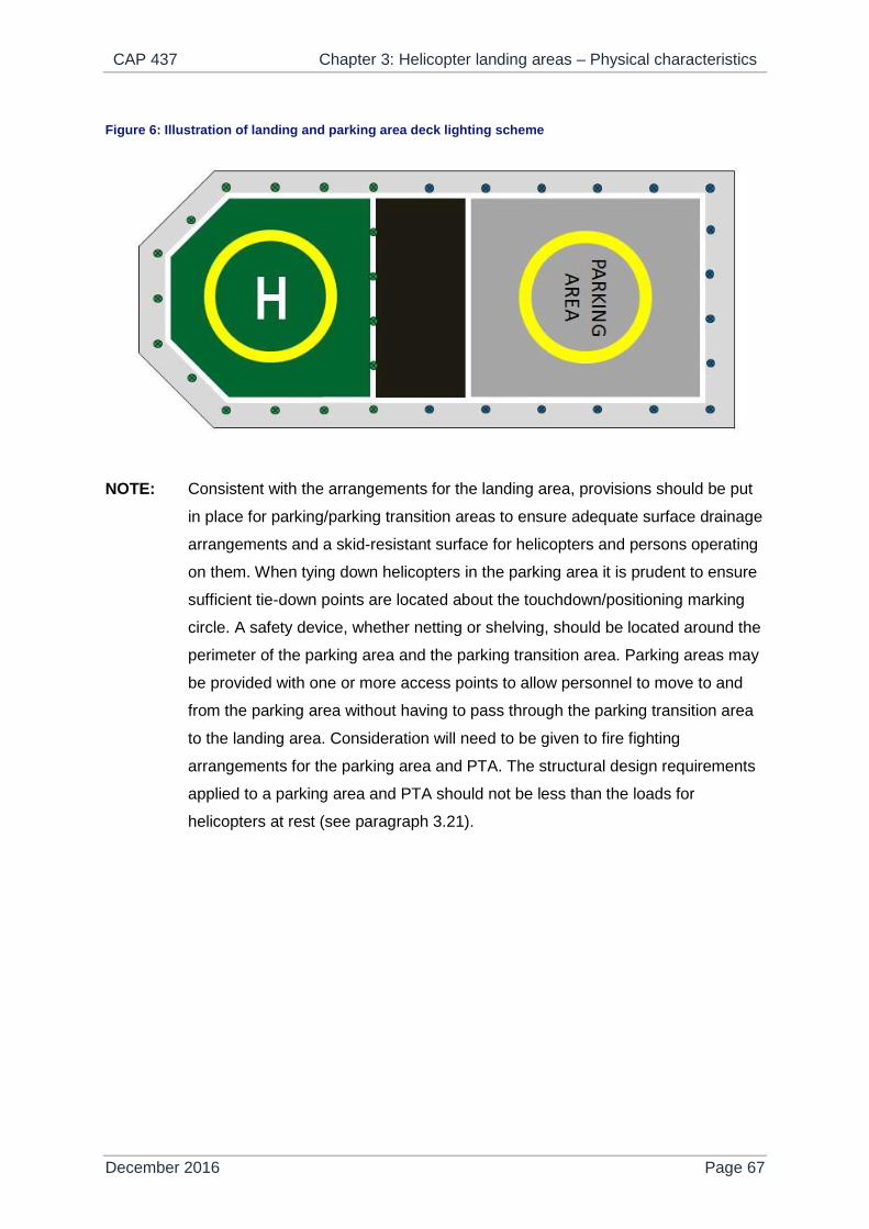
CAP 437 Chapter 3: Helicopter landing areas – Physical characteristics
December 2016 Page 67
Figure 6: Illustration of landing and parking area deck lighting scheme
NOTE: Consistent with the arrangements for the landing area, provisions should be put
in place for parking/parking transition areas to ensure adequate surface drainage
arrangements and a skid-resistant surface for helicopters and persons operating
on them. When tying down helicopters in the parking area it is prudent to ensure
sufficient tie-down points are located about the touchdown/positioning marking
circle. A safety device, whether netting or shelving, should be located around the
perimeter of the parking area and the parking transition area. Parking areas may
be provided with one or more access points to allow personnel to move to and
from the parking area without having to pass through the parking transition area
to the landing area. Consideration will need to be given to fire fighting
arrangements for the parking area and PTA. The structural design requirements
applied to a parking area and PTA should not be less than the loads for
helicopters at rest (see paragraph 3.21).

CAP 437 Chapter 4: Visual aids
December 2016 Page 68
Chapter 4
Visual aids
General
4.1 The name of the installation should be clearly displayed in such positions
on the installation so that it can be readily identified from the air and sea
from all normal angles and directions of approach. For identification from
the air the helideck name and the side identification panels are used. It is
not necessary, nor is it a legal requirement, to complicate recognition
processes by inclusion of ‘block numbers’, company logos, or other
designators. In fact, complication of identifiers can be confusing and will
unnecessarily, and undesirably, extend the mental process of recognition
at the critical time when the pilots’ concentration is being fully exercised
by the demands of the landing manoeuvre. The names on both
identification markings should be identical, simple and unique and
facilitate unambiguous communication via radio. The approved radio
callsign of the installation should be the same name as painted on the
helideck and displayed on the side panel identifier. Where the inclusion of
‘block numbers’ on side identification panels is deemed to be essential
(i.e. for purposes other than recognition), the name of the installation
should also be included; e.g. ‘NAME. BLOCK NO.’ The installation
identification panels should be highly visible in all light conditions and from
all directions of approach. They should be suitably illuminated at night and
in conditions of poor visibility. In order to minimise the possibility of ‘wrong
rig landings’ use of new technology is encouraged so that identification
can be confirmed in the early stages of the approach by day and night.
Modern technology is capable of meeting this requirement in most
ambient lighting conditions. Use of high-intensity Light Emitting Diode
(LED) cluster or fibre-optic systems in other applications have been
shown to be effective even in severely reduced visibility. Additionally, it is
recognised that alternative technologies have been developed consisting

CAP 437 Chapter 4: Visual aids
December 2016 Page 69
of highly visible reflective side signage that has been successfully
installed on some installations with the co-operation of the helicopter
operator. (HSE Operations Notice 39, re-issued in June 2008, provides
‘Guidance on Identification of Offshore Installations’.)
4.2 Helideck markings (specifically the installation identification marking) and
side identification panels are used by pilots to obtain a final pre-landing
confirmation that the correct helideck is being approached. It is therefore
VITAL that the helideck markings and side identification panels are
maintained in the best possible condition, regularly re-painted and kept
free of all visibility-reducing contaminants. Helideck owners/operators
should ensure that specific inspection and re-painting maintenance
procedures and schedules for helideck markings and side identification
panels take account of the importance of their purpose. Side identification
panels should be kept free of any obscuring paraphernalia (draped hoses
etc.) and be as high as possible on the structure.
4.3 The installation identification (see paragraphs 4.1 and 4.2) should be
marked in white characters on the helideck surface between the origin of
the OFS and the TD/PM Circle in symbols not less than 1.2 metres where
a helideck is below 16.0m. For all helidecks 16.0m and greater, whether
new builds or at the next scheduled repaint, the character height should
be increased to 1.5m in white which contrasts with the helideck surface.
The name should not be obscured by the deck net (where fitted). For an
unpainted aluminium surface the installation identification (in white
characters) should be displayed against a black background.
4.4 Helideck perimeter line marking and lighting serves to identify the limits of
the Landing Area (see Glossary) for day and night operations
respectively.
4.5 A wind direction indicator (windsock) should be provided and located so
as to indicate the free stream wind conditions at the installation/vessel
location. It is often inappropriate to locate the primary windsock as close
to the helideck as possible where it may compromise obstacle protected
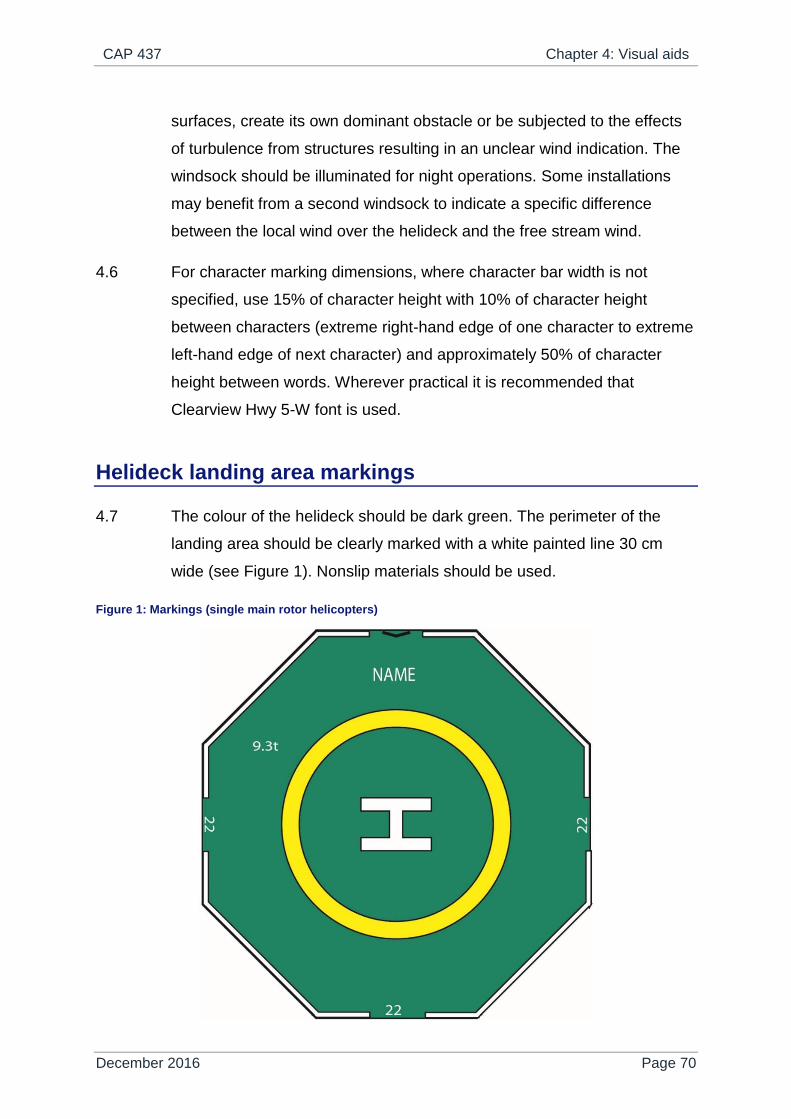
CAP 437 Chapter 4: Visual aids
December 2016 Page 70
surfaces, create its own dominant obstacle or be subjected to the effects
of turbulence from structures resulting in an unclear wind indication. The
windsock should be illuminated for night operations. Some installations
may benefit from a second windsock to indicate a specific difference
between the local wind over the helideck and the free stream wind.
4.6 For character marking dimensions, where character bar width is not
specified, use 15% of character height with 10% of character height
between characters (extreme right-hand edge of one character to extreme
left-hand edge of next character) and approximately 50% of character
height between words. Wherever practical it is recommended that
Clearview Hwy 5-W font is used.
Helideck landing area markings
4.7 The colour of the helideck should be dark green. The perimeter of the
landing area should be clearly marked with a white painted line 30 cm
wide (see Figure 1). Nonslip materials should be used.
Figure 1: Markings (single main rotor helicopters)

CAP 437 Chapter 4: Visual aids
December 2016 Page 71
4.8 Aluminium helidecks are in use throughout the offshore industry. Some of
these are a natural light grey colour and may present painting difficulties.
The natural light grey colour of aluminium may be acceptable in specific
helideck applications where these are agreed with the agency responsible
for the certification of the helideck. This should be discussed in the early
design phase. In such cases the conspicuity of the helideck markings may
need to be enhanced by, for example, overlaying white markings on a
painted black background. Additionally, conspicuity of the yellow TD/PM
Circle may be enhanced by outlining the deck marking with a thin black
line (typically 10 cm).
4.9 The origin of the 210° OFS for approach and take-off as specified in
Chapter 3 should be marked on the helideck by a black chevron, each leg
being 79 cm long and 10 cm wide forming the angle in the manner shown
in Figure 2. On minimum sized helidecks where there is no room to place
the chevron where indicated, the chevron marking, but not the point of
origin, may be displaced towards the D-circle centre. Where the OFS is
swung in accordance with the provision of Chapter 3 paragraph 3.25 this
should be reflected in the alignment of the chevron. The purpose of the
chevron is to provide visual guidance to the HLO so that he can ensure
that the 210° OFS is clear of obstructions before giving a helicopter
clearance to land. The black chevron may be painted on top of the
(continuous) white perimeter line to achieve maximum clarity for the
helideck crew.

CAP 437 Chapter 4: Visual aids
December 2016 Page 72
Figure 2: Helideck D-value and obstacle-free marking
4.10 The actual D-value of the helideck (see Chapter 3, paragraph 3.22)
should be painted on the helideck adjacent to, and where practical
inboard of, the chevron in alphanumeric symbols 10 cm high. Where, for
an existing installation, a helideck has been accepted which does not
meet the normal minimum OFS requirements of 210°, the black chevron
should represent the angle which has been accepted and this value
should be marked inboard of the chevron in a similar manner to the
certificated D-value. It is expected that new-builds will always comply in
full with the requirement to provide a minimum 210° OFS.
4.11 The helideck D-value should also be marked around the perimeter of the
helideck in white characters no less than 90 cm high, in the manner
shown in Figures 1 and 2. The D-value should be expressed to the
nearest whole number with 0.5 rounded down, e.g. 18.5 marked as 18
(see Chapter 3, Table 1). For an unpainted aluminium surface helideck D-

CAP 437 Chapter 4: Visual aids
December 2016 Page 73
value(s) (in white characters) should be displayed against a black
background.
NOTE: Helidecks designed specifically for AS332L2 and EC 225 helicopters, each
having a D-value of 19.5 m, should be rounded up to 20 in order to differentiate
between helidecks designed specifically for L1 models. For helidecks where the
actual D-value is less than 15.00 m, the height of the numbers may be reduced
from 90 cm to no less than 60 cm.
4.12 A maximum allowable mass marking should be marked on the helideck in
a position which is readable from the preferred final approach direction,
i.e. towards the OFS origin. The marking should consist of a two- or three-
digit number expressed to one decimal place rounded to the nearest 100
kg and followed by the letter ‘t’ to indicate the allowable helicopter mass in
tonnes (1000 kg). The height of the figures should be 90 cm with a line
width of approximately 12 cm and should be white i.e. be in a colour which
contrasts with the helideck surface. For an unpainted aluminium surface a
maximum alllowable mass marking (in white characters) should be
displayed against a black background. Where possible the mass marking
should be well separated from the installation identification marking (see
paragraph 4.3) in order to avoid possible confusion on recognition. Refer
also to Figure 1 and Chapter 3, Table 1.
4.13 A Touchdown/Positioning Marking (TD/PM) should be provided (see
Figures 1 and 3). The marking should be a yellow circle with an inner
diameter of 0.5 of the certificated D-value of the helideck and a line width
of 1 metre (for new build helidecks below 16m the line width may be
reduced to 0.5m). The centre of the marking should be concentric with the
centre of the D-circle.
CAP 437 Chapter 4: Visual aids
December 2016 Page 74
Figure 3: Touchdown/Positioning marking circle (TD/PM circle to be painted yellow
NOTE: On a helideck the centre of the TD/PM Circle will normally be located at the
centre of the landing area, except that the marking may be offset away from the
origin of the OFS by no more than 0.1D where an aeronautical study indicates
such offsetting to be beneficial, provided that the offset marking does not
adversely affect the safety of flight operations or ground handling issues.
4.14 A white heliport identification marking ‘H’ marking should be marked co-
located with the TD/PM with the cross bar of the ‘H’ lying along the
bisector of the OFS. Its dimensions are as shown in Figure 4. For new
build helidecks having a D-value below 16.0m, the dimensions of the 'H'
marking may be reduced to 3m x 2m x 0.5m.

CAP 437 Chapter 4: Visual aids
December 2016 Page 75
Figure 4: Dimensions of heliport identification marking 'H' ('H' to be painted white)
4.15 Where the OFS has been swung in accordance with Chapter 3 paragraph
3.25 the positioning of the TD/PM and ‘H’ should comply with the normal
unswung criteria. However, the ‘H’ should be orientated so that the bar is
parallel to the bisector of the swung sector.
4.16 Prohibited landing heading sectors should be marked where it is
necessary to protect the tail of the helicopter from landing or manoeuvring
in close proximity to limiting obstructions which, for example, infringe the
150° LOS protected surfaces. When required, prohibited sectors are to be
shown by red hatching of the TD/PM, with white and red hatching
extending from the red hatching out to the edge of the landing area as
shown in Figures 5 and 6.
NOTE: When positioning over the TD/PM helicopters should be manoeuvred so as to
keep the aircraft nose clear of the hatched prohibited sector(s) at all times.
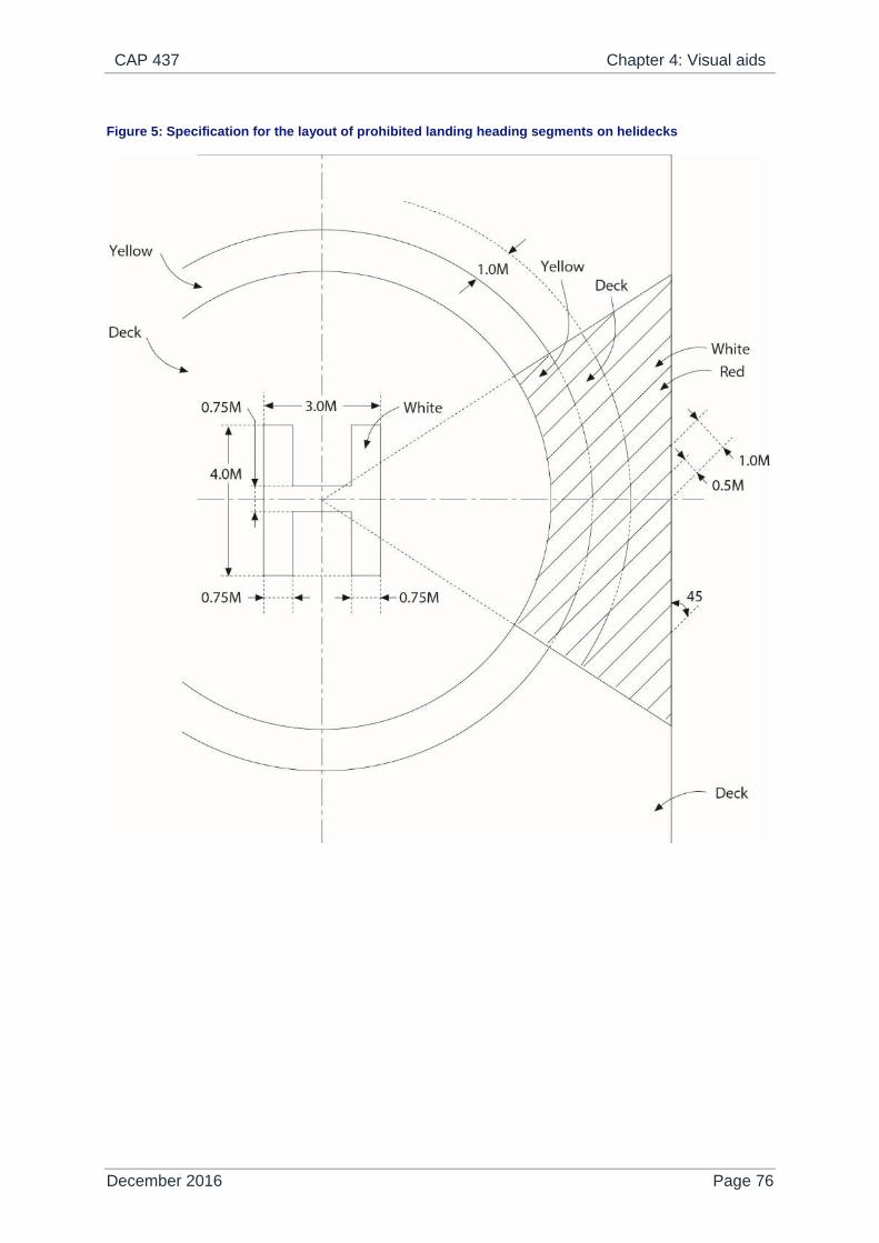
CAP 437 Chapter 4: Visual aids
December 2016 Page 76
Figure 5: Specification for the layout of prohibited landing heading segments on helidecks

CAP 437 Chapter 4: Visual aids
December 2016 Page 77
Figure 6: Example of prohibited landing heading marking
NOTE: The position of the ‘H’ and the orientation of the prohibited landing heading
segment will depend on the obstacle.
4.17 For certain operational or technical reasons an installation may have to
prohibit helicopter operations. In such circumstances, where the helideck
cannot be used, the ‘closed’ state of the helideck should be indicated by
use of the signal shown in Figure 7. This signal is the standard ‘landing
prohibited’ signal given in the Rules of the Air and Air Traffic Control
Regulations, except that it has been altered in size to just cover the letter
‘H’ inside the TD/PM.

CAP 437 Chapter 4: Visual aids
December 2016 Page 78
Figure 7: Landing on installation/vessel prohibited
NOTE: Signal covers ‘H’ inside TD/PM.
4.18 Colours should conform with the following BS 381C (1996) standard or
the equivalent BS 4800 colour. White should conform to the RAL charts.
RED
BS 381C: 537 / RAL 3001 (Signal Red)
BS 4800: 04.E.53 / RAL 2002 (Poppy)
YELLOW
BS 381C: 309 / RAL1018 (Canary Yellow)
BS 4800: 10.E.53 / RAL1023 (Sunflower Yellow)
DARK GREEN
BS 381C: 267 / RAL 6020 (Deep Chrome Green)
BS 4800: 14.C.39 (Holly Green)
WHITE
RAL 9010 (Pure White)
RAL 9003 (Signal White)

CAP 437 Chapter 4: Visual aids
December 2016 Page 79
Lighting
NOTE 1: The paragraphs below should be read in conjunction with Appendix C which
contains the specification for the full helideck lighting scheme comprising
perimeter lights, lit TD/PM Circle and lit heliport identification "H" marking. The
specification for each element is fully described in Appendix C with the overall
operational requirement detailed in paragraph 1 of the Appendix. The helideck
lighting scheme is a requirement for the conduct of night operations and is
intended to provide effective visual cues for a pilot throughout the approach and
landing manoeuvre at night. Starting with the initial acquisition of the helideck,
the lighting needs to enable a pilot to easily locate the position of the helideck on
the installation at long range on an often well lit offshore structure. The lighting
should then guide the helicopter to a point above the landing area and then
provide visual cues to assist with the touchdown. At night, when a helideck is not
in use, and to mitigate the possibility of a 'wrong rig landing' on an unsafe
helideck, the Lit Touchdown/ Positioning Marking and Lit Heliport Identification
Marking and/or helideck floodlighting should be extinguished. However, green
perimeter lights should remain 'on' so that the outline of the helideck can be
distinguished from the air.
NOTE 2: The specification has an in-built assumption that the performance of the helideck
lighting system will not be diminished by any other lighting due to the relative
intensity, configuration or colour of other lighting sources on the installation or
vessel. Where other non-aeronautical ground lights have the potential to cause
confusion or to diminish or prevent the clear interpretation of helideck lighting
systems, it will be necessary for an installation or vessel operator to extinguish,
screen or otherwise modify these lights to ensure that the effectiveness of the
helideck lighting system is not compromised. This will include, but may not be
limited to, an assessment of the effect of general installation lighting on the
performance of the helideck lighting scheme. The CAA recommends that
installation and vessel operators give serious consideration to shielding high
intensity light sources (e.g. by fitting screens or louvers) from helicopters
approaching and landing, and maintaining a good colour contrast between the
helideck lighting and surrounding installation lighting. Particular attention should
be paid to the areas of the installation adjacent to the helideck.

CAP 437 Chapter 4: Visual aids
December 2016 Page 80
NOTE 3: The specification contained in Appendix C includes a facility to increase the
intensity of some elements of the helideck lighting to compensate for installations
or vessels with high levels of background lighting. The setting of the intensity of
the helideck lighting should be carried out in conjunction with the helicopter
operator as a once-off exercise following installation of the lighting, and
subsequently if required following changes to the lighting environment at the
installation or vessel. The intensity of the helideck lighting should not be routinely
changed, and in any event should not be altered without the involvement and
agreement of the helicopter operator.
Perimeter lighting
4.19 The periphery of the landing area should be delineated by omni-
directional green perimeter lights visible from on or above the landing
area; however, the pattern formed by the lights should not be visible to the
pilot from below the elevation of the landing area. Perimeter lights should
be mounted above the level of the helideck but should not exceed the
height limitations specified in Appendix C, paragraph C.16. The lights
should be equally spaced at intervals of not more than three metres
around the perimeter of the landing area, coincident to or adjacent with
the white line delineating the perimeter (see paragraph 4.7 above). In the
case of square or rectangular decks there should be a minimum of four
lights along each side including a light at each corner of the landing area.
Recessed helideck perimeter lights may be used at the inboard (150° LOS
origin) edge of the landing area where an operational need exists to move
large items of equipment to and from the landing area, e.g. where a run-
off area is provided there may be a need to move the helicopter itself to
and from the landing area onto the adjacent run-off (parking) area. Care
should be taken to select recessed helideck perimeter lights that will meet
the iso-candela requirements stated in Appendix C, Table 2.
4.20 Where the declared D-value of the helideck is less than the physical
helideck area, the perimeter lights should be coincidental with the white
perimeter marking and black chevron and delineate the limit of the
useable landing area so that, in unusual circumstances where a helicopter
CAP 437 Chapter 4: Visual aids
December 2016 Page 81
touches down inboard of the TD/PM Circle, it can land safely by reference
to the perimeter lights on the 150° LOS ‘inboard’ side of the helideck
without risk of the main rotor striking obstructions in this sector. By
applying the LOS clearances (given in Chapter 3, paragraphs 3.26 to
3.27) from the perimeter marking and coincident lighting, adequate main
rotor to obstruction separation should be achieved for the worst-case
helicopter intended to operate to the helideck.
Floodlighting, lit TD/PM circle and lit heliport identification ‘H’
marking
4.21 In order to aid the visual task of final approach and hover and landing it is
important that adequate visual cues be provided. For use at night, this has
previously been achieved using floodlighting; however, these systems can
adversely affect the visual cueing environment by reducing the conspicuity
of helideck perimeter lights during the approach, and by causing glare and
loss of pilots' night vision during the hover and landing. Furthermore,
floodlighting systems often fail to provide adequate illumination of the
centre of the landing area leading to the so-called 'black-hole effect'.
4.22 A new lighting scheme comprising a lit TD/PM Circle and a lit heliport
identification 'H' marking has therefore been developed and is effectively
mandated for operations taking place at night on the UKCS from 1st April
2018. This scheme, described in detail in Appendix C, has been clearly
demonstrated to provide the visual cues required by the pilot earlier on in
the approach, and much more effectively than floodlighting and without
the disadvantages associated with floodlights such as glare. The CAA has
therefore replaced the traditional floodlighting systems with the new
offshore helideck lighting scheme meeting the specification given in
Appendix C.
NOTE 1: As a result of the G-REDU accident in February 2009, the Air Accidents
Investigation Branch (AAIB) has published Air Accident Report 1/2011 which
addresses a number of safety recommendations including Safety
Recommendation 2011-053 recommending the amendment of CAP 437 to

CAP 437 Chapter 4: Visual aids
December 2016 Page 82
encourage operators of vessels and offshore installations equipped with
helidecks to adopt the new lighting standard presented as a final specification in
Appendix C.
NOTE 2: The new lighting scheme has been developed to be compatible with helicopters
having wheeled undercarriages, this being the prevailing configuration on the
UKCS during the development of the specification and at the time of publication.
Although the design specifications detailed in Appendix C will ensure the
segments and subsections containing lighting elements are compliant with the
ICAO maximum obstacle height of 25 mm and likely to be able to withstand the
point loading presented by (typically) lighter skidded aircraft, compatibility should
be considered before operating skidded helicopters to helidecks fitted with the
new lighting. Due to the potential for raised fittings to induce dynamic rollover of
helicopters equipped with skids, it is important that, where the new lighting
scheme is installed on helidecks used by skid-fitted helicopters, the height of the
system (including any mounting arrangements) should be kept as low as
possible.
4.23 Although no longer recommended for the provision of primary visual
cueing, the CAA has no objection to floodlighting systems conforming to
the guidance contained in Appendix G being retained for the purpose of
providing a source of illumination for on-deck operations such as refuelling
and passenger handling and, where required, for lighting the installation
name on the helideck surface or as a back-up to the new lighting (see
Note 2 below). Unless otherwise instructed by the aircrew the floodlights
should be switched off during the acquisition, approach to hover, landing
and take-off phases. In addition, particular care should be taken to
maintain correct alignment to ensure that floodlights do not cause dazzle
or glare to pilots while either in-flight or landed on the helideck. All
floodlights should be capable of being switched on and off at the pilot's
request. The floodlighting controls should be accessible to, and controlled
by, the HLO or Radio Operator.
4.24 For helidecks located on normally unattended installations (NUIs), it is
essential to ensure that the main structure of the platform (or 'legs') are
adequately illuminated to improve depth perception and to mitigate the

CAP 437 Chapter 4: Visual aids
December 2016 Page 83
visual illusion that the landing area appears to be 'floating in space'. This
is best achieved by providing, in consultation with the helicopter
operator(s), floodlighting of the main structure beneath the helideck. Care
should be taken to ensure that any potential source of glare from structure
lighting is eliminated by directing it away from the approach path of the
helicopter, and/or by providing louvres as appropriate.
NOTE: Prior to 1st April 2018 floodlighting may be retained as a temporary source of
alternative helideck lighting, e.g. in the event of guano rendering the new circle-H
lighting ineffective on some NUIs. It is the CAA's view that the guano problem
should be addressed, but it may nevertheless be desirable to retain Appendix G
compliant floodlighting as a temporary back-up on some installations.
Helideck status light system
4.25 A visual warning system should be installed if a condition can exist on an
installation which may be hazardous for the helicopter or its occupants.
The system (Status Lights) should be a flashing red light (or lights), visible
to the pilot from any direction of approach and on any landing heading.
The aeronautical meaning of a flashing red light is either “do not land,
aerodrome not available for landing” or “move clear of landing area”. The
system should be automatically initiated at the appropriate hazard level
(e.g. gas release) as well as being capable of manual activation by the
HLO. It should be visible at a range in excess of the distance at which the
helicopter may be endangered or may be commencing a visual approach.
CAA Paper 2008/01 provides a specification for a status light system
which is summarised below:
Where required, the helideck status signalling system should be
installed either on or adjacent to the helideck. Additional lights may
be installed in other locations on the platform where this is necessary
to meet the requirement that the signal be visible from all approach
directions, i.e. 360° in azimuth.

CAP 437 Chapter 4: Visual aids
December 2016 Page 84
The effective intensity should be a minimum of 700 cd between 2°
and 10° above the horizontal and at least 176 cd at all other angles
of elevation.
The system should be provided with a facility to enable the output of
the lights (if and when activated) to be dimmed to an intensity not
exceeding 60 cd while the helicopter is landed on the helideck.
The signal should be visible from all possible approach directions
and while the helicopter is landed on the helideck, regardless of
heading, with a vertical beam spread as shown in the second bullet
point above.
The colour of the status light(s) should be red, as defined in ICAO
Annex 14 Volume 1 Appendix 1, Colours for aeronautical ground
lights.
The light system as seen by the pilot at any point during the
approach should flash at a rate of 120 flashes per minute. Where
two or more lights are needed to meet this requirement, they should
be synchronised to ensure an equal time gap (to within 10%)
between flashes. While landed on the helideck, a flash rate of 60
flashes per minute is acceptable. The maximum duty cycle should be
no greater than 50%.
The light system should be integrated with platform safety systems
such that it is activated automatically in the event of a process upset.
Facilities should be provided for the HLO to manually switch on the
system and/or override automatic activation of the system.
The light system should have a response time to the full intensity
specified not exceeding three seconds at all times.
Facilities should be provided for resetting the system which, in the
case of NUIs, do not require a helicopter to land on the helideck.
The system should be designed so that no single failure will prevent
the system operating effectively. In the event that more than one
light unit is used to meet the flash rate requirement, a reduced flash
frequency of at least 60 flashes per minute is considered acceptable
in the failed condition for a limited period.

CAP 437 Chapter 4: Visual aids
December 2016 Page 85
The system and its constituent components should comply with all
regulations relevant to the installation.
Where the system and its constituent components are mounted in
the 210º OFS or in the first segment of the LOS, the height of the
installed system should not exceed 25 cm above deck level (or
exceed 5 cm for any helideck where the D-value is 16.00 m or less).
Where supplementary ‘repeater’ lights are employed for the
purposes of achieving the ‘on deck’ 360° coverage in azimuth, these
should have a minimum intensity of 16 cd and a maximum intensity
of 60 cd for all angles of azimuth and elevation
4.26 All components of the status light system should be tested by an
independent test house to ensure verification with the specification in CAA
Paper 2008/01. The photometrical and colour measurements performed in
the optical department of the test house should be accredited according to
the version of EN ISO/IEC 17025 current at the time of the testing.
4.27 Manufacturers are reminded that the minimum intensity specification
stated above is considered acceptable to meet the current operational
requirements, which specify a minimum meteorological visibility of 1400 m
(0.75 NM). Development of offshore approach aids which permit lower
minima (e.g. differential GPS) will require a higher intensity. Revised
intensities are specified for the lowest anticipated meteorological visibility
of 900 m (0.5 NM) in CAA Paper 2008/01, Appendix A.
4.28 Where helideck status light systems installed on normally unattended
installations (NUIs) malfunction, whether the outcome is light(s)
permanently flashing or disabled/depowered, in these cases, to allow
them to be manually reset at the platform, a duty-holder may present a
case-specific risk assessment to the helicopter operator, who if satisfied
with the duty-holder's risk assessment, may raise a dispensation request
to CAA Flight Operations (Helicopters) that, where accepted, would permit
flights against operating status lights or black platforms to occur. A CAA
CAP 437 Chapter 4: Visual aids
December 2016 Page 86
Protocol for operations against operating status lights or black decks is
attached at Appendix I.
UPS requirement
4.29 Installation/vessel emergency power supply design should include the
entire landing area lighting system (see Appendix C). Any failures or
outages should be reported immediately to the helicopter operator. The
lighting should be fed from an Uninterruptable Power Supply (UPS)
system.
Obstacles – Marking and lighting
4.30 Fixed obstacles which present a hazard to helicopters should be readily
visible from the air. If a paint scheme is necessary to enhance
identification by day, alternate black and white, black and yellow, or red
and white bands are recommended, not less than 0.5 metres nor more
than six metres wide. The use of 'Day-Glo' orange may also be
acceptable. The colour should be chosen to contrast with the background
to the maximum extent. Paint colours should conform to the references at
paragraph 4.18.
4.31 Obstacles to be marked in these contrasting colours include any lattice
tower structures and crane booms, in addition to obstacles which are
close to the helideck or the LOS boundary. Similarly, parts of the leg or
legs of jack-up units adjacent to the landing area which extend, or can
extend, above it should also be marked in the same manner. Lattice
towers should be painted in their entirety.
4.32 Omnidirectional low intensity steady red obstruction lights conforming to
the specifications for low intensity obstacle (Group A) lights described in
CAP 168 Licensing of Aerodromes, Chapter 4 and Table 6A.1, having a
minimum intensity of 10 candelas for angles of elevation between 0
degrees and 30 degrees should be fitted at suitable locations to provide
the helicopter pilot with visual information on the proximity and height of

CAP 437 Chapter 4: Visual aids
December 2016 Page 87
objects which are higher than the landing area and which are close to it or
to the LOS boundary. This should apply, in particular, to all crane booms
on the installation or vessel. Objects which are more than 15 metres
higher than the landing area should be fitted with intermediate low
intensity steady red obstruction lights of the same intensity spaced at 10-
metre intervals down to the level of the landing area (except where such
lights would be obscured by other objects). It is often preferable for some
structures such as flare booms and towers to be illuminated by floodlights
as an alternative to fitting intermediate steady red lights, provided that the
lights are arranged such that they will illuminate the whole of the structure
and not dazzle the helicopter pilot. Such arrangements should be
discussed with the helicopter operator. Offshore duty holders may, where
appropriate, consider alternative equivalent technologies to highlight
dominant obstacles in the vicinity of the helideck.
4.33 An omni-directional low intensity steady red obstruction light should be
fitted to the highest point of the installation. The light should conform to
the specifications for a low intensity obstacle (Group B) light described in
CAP 168 Licensing of Aerodromes, Chapter 4 and Table 6A.1, having a
minimum intensity of 50 candelas for angles of elevation between 0 and
15 degrees, and a minimum intensity of 200 candelas between 5 and 8
degrees. Where it is not practicable to fit a light to the highest point of the
installation (e.g. on top of flare towers) the light should be fitted as near to
the extremity as possible.
4.34 In the particular case of jack-up units, it is recommended that when the
tops of the legs are the highest points on the installation, they should be
fitted with omni-directional low intensity steady red lights of the same
intensity and characteristics as described in paragraph 4.33. In addition
the leg or legs adjacent to the helideck should be fitted with intermediate
low intensity steady red lights of the same intensity and characteristics as
described in paragraph 4.32 at 10-metre intervals down to the level of the
landing area. As an alternative the legs may be floodlit providing the
helicopter pilot is not dazzled.

CAP 437 Chapter 4: Visual aids
December 2016 Page 88
4.35 Any ancillary structure within one kilometre of the landing area, and which
is 10m or more above helideck height, should be similarly fitted with red
lights.
4.36 Red lights should be arranged so that the locations of the objects which
they delineate are visible from all directions of approach above the landing
area.
4.37 Installation/vessel emergency power supply design should include all
forms of obstruction lighting. Any failures or outages should be reported
immediately to the helicopter operator. The lighting should be fed from a
UPS system.

CAP 437 Chapter 5: Helideck rescue and fire fighting facilities
December 2016 Page 89
Chapter 5
Helideck rescue and fire fighting facilities
Introduction
5.1 This Chapter sets out the requirements regarding provision of equipment,
extinguishing media, personnel, training, and emergency procedures for
offshore helidecks on installations and vessels.
Key design characteristics – Principal agent
5.2 A key aspect in the successful design for providing an efficient, integrated
helideck rescue and fire fighting facility is a complete understanding of the
circumstances in which it may be expected to operate. A helicopter
accident, which results in a fuel spillage with wreckage and/or fire and
smoke, has the capability to render some of the equipment inventory
unusable or preclude the use of some passenger escape routes.
5.3 Delivery of fire fighting media to the landing area at the appropriate
application rate should be achieved in the quickest possible time. The
CAA strongly recommends that a delay of less than 15 seconds,
measured from the time the system is activated to actual production at the
required application rate, should be the objective. The operational
objective should ensure that the system is able to bring under control a
helideck fire associated with a crashed helicopter within 30 seconds
measured from the time the system is producing foam at the required
application rate for the range of weather conditions prevalent for the
UKCS.
NOTE: A fire is deemed to be ‘under control’ at the point when it becomes possible for
the occupants of the helicopter to be effectively rescued by trained fire-fighters.
5.4 Foam-making equipment should be of adequate performance and be
suitably located to ensure an effective application of foam to any part of

CAP 437 Chapter 5: Helideck rescue and fire fighting facilities
December 2016 Page 90
the landing area irrespective of the wind strength/direction or accident
location when all components of the system are operating in accordance
with the manufacturer’s technical specifications for the equipment.
However, for a Fixed Monitor System (FMS), consideration should also be
given to the loss of a downwind foam monitor either due to limiting
weather conditions or a crash situation occurring. The design specification
for an FMS should ensure remaining monitors are capable of delivering
foam to the landing area at or above the minimum application rate. For
areas of the helideck or its appendages which, for any reason, may be
otherwise inaccessible to an FMS, it is necessary to provide additional
hand-controlled foam branches as described in paragraph 5.12.
5.5 Consideration should be given to the effects of the weather on static
equipment. All equipment forming part of the facility should be designed to
withstand protracted exposure to the elements or be protected from them.
Where protection is the chosen option, it should not prevent the
equipment being brought into use quickly and effectively (see paragraph
5.3). The effects of condensation on stored equipment should be
considered.
5.6 The minimum capacity of the foam production system will depend on the
D-value of the helideck, the foam application rate, discharge rates of
installed equipment and the expected duration of application. It is
important to ensure that the capacity of the main helideck fire pump is
sufficient to guarantee that finished foam can be applied at the
appropriate induction ratio and application rate and for the minimum
duration to the whole of the landing area when all helideck monitors are
being discharged simultaneously.
5.7 The application rate is dependent on the types of foam concentrate in use
and the types of foam application equipment selected. For fires involving
aviation kerosene, ICAO has produced a performance test which
assesses and categorises the foam concentrate. Most foam concentrate
manufacturers will be able to advise on the performance of their

CAP 437 Chapter 5: Helideck rescue and fire fighting facilities
December 2016 Page 91
concentrate against this test. The CAA recommends that foam
concentrates compatible with seawater and meeting at least performance
level ‘B’ are used. Level B foams should be applied at a minimum
application rate of 6.0 litres per square metre per minute.
5.8 Calculation of Application Rate: Example for a D-value 22.2 metre
helideck (Level B foams) Application rate = 6.0 x π x r² (6.0 x 3.142 x 11.1
x 11.1) = 2322 litres per minute.
NOTE: ICAO Annex 14 Volume I and the Doc. 9137-AN/898 Airport Services Manual,
Part 1 - Rescue and Fire-fighting Fourth Edition 2015 support the use of
performance level C foams which are proven to be more efficient in their
extinguishing ability than level B foams. It is established that the application rate
for foam meeting performance level C may be reduced to 3.75 litres per square
metre per minute and, where level C foams are selected for new systems, 3.75
may be used in the calculation in lieu of 6.0 litres.
Calculation of Application Rate: Example for a D-value 22.2 metre helideck
(Level C foams) Application rate = 3.75 x π x r² (3.75 x 3.142 x 11.1 x 11.1) =
1452 litres per minute.
5.9 Given the remote location of helidecks the overall capacity of the foam
system should exceed that necessary for initial extinction of any fire. Five
minutes’ discharge capability is generally considered by the CAA to be
reasonable.
5.10 Calculation of Minimum Operational Stocks: Using the 22.2 metre
example as shown in paragraph 5.8, a 1% foam solution discharged over
five minutes at the minimum application rate will require 2322 x 1% x 5 =
116 litres of foam concentrate. A 3% foam solution discharged over five
minutes at the minimum application rate will require 2322 x 3% x 5 = 348
litres of foam concentrate.
NOTE: Sufficient reserve foam stocks to allow for replenishment as a result of operation
of the system during an incident, or following training or testing, will also need to
be held.
CAP 437 Chapter 5: Helideck rescue and fire fighting facilities
December 2016 Page 92
5.11 Low expansion foam concentrates can generally be applied in either
aspirated or unaspirated form. It should be recognised that whilst
unaspirated foam may provide a quick knockdown of any fuel fire,
aspiration, i.e. induction of air into the foam solution by monitor or by
hand-controlled foam branch (see below), gives enhanced protection after
extinguishment. Wherever non-aspirated foam equipment is selected
during design, additional equipment capable of producing aspirated foam
for post-fire security/control should be provided.
5.12 Not all fires are capable of being accessed by monitors and on some
occasions the use of monitors may endanger passengers. Therefore, in
addition to a fixed foam system monitor, there should be the ability to
deploy at least two deliveries with hand-controlled foam branches for the
application of aspirated foam at a minimum rate of 225 litres/min through
each hose line. A single hose line, capable of delivering aspirated foam at
a minimum application rate of 225 litres/min, may be acceptable where it
is demonstrated that the hose line is of sufficient length, and the hydrant
system of sufficient operating pressure, to ensure the effective application
of foam to any part of the landing area irrespective of wind strength or
direction. The hose line(s) provided should be capable of being fitted with
a branch pipe capable of applying water in the form of a jet or spray
pattern for cooling, or for specific fire fighting tactics. Where a Deck
Integrated Fire Fighting System (DIFFS) capable of delivering foam and/or
seawater in a spray pattern to the whole of the landing area (see
paragraphs 5.13 to 5.15 and Note below) is selected in lieu of an FMS,
the provision of additional hand-controlled foam branches may not be
necessary to address any residual fire situation. Instead any residual fire
may be tackled with the use of hand-held extinguishers (see paragraph 4).
5.13 As an effective alternative to an FMS, offshore duty holders are strongly
encouraged to consider the provision of DIFFS. These systems typically
consist of a series of 'pop-up' nozzles, with both a horizontal and vertical
component, designed to provide an effective spray distribution of foam to
the whole of the landing area and protection for the helicopter for the

CAP 437 Chapter 5: Helideck rescue and fire fighting facilities
December 2016 Page 93
range of weather conditions prevalent on the UKCS. A DIFFS should be
capable of supplying performance level B or level C foam solution to bring
under control a fire associated with a crashed helicopter within the time
constraints stated in paragraph 5.3 achieving an average (theoretical)
application rate over the entire landing area (based on the D-circle) of 6.0
litres per square metre per minute for level B foams or 3.75 litres per
square metre per minute for level C foams, for a duration which at least
meets the minimum requirements stated in paragraph 5.9.
5.14 The precise number and layout of pop-up nozzles will be dependent on
the specific helideck design, particularly the dimensions of the critical
area. However, nozzles should not be located adjacent to helideck egress
points as this may hamper quick access to the helideck by trained rescue
crews and/or impede occupants of the helicopter escaping to a safe place
beyond the helideck. Notwithstanding this, the number and layout of
nozzles should be sufficient to provide an effective spray distribution of
foam over the entire landing area with a suitable overlap of the horizontal
element of the spray pattern from each nozzle assuming calm wind
conditions. It is recognised in meeting the objective for the average
(theoretical) application rate specified in paragraph 2.10 for performance
level B or C foams that there may be some areas of the helideck,
particularly where the spray patterns of nozzles significantly overlap,
where the average (theoretical) application rate is exceeded in practice.
Conversely for other areas of the helideck the application rate in practice
may fall below the average (theoretical) application rate specified in
paragraph 5.13. This is acceptable provided that the actual application
rate achieved for any portion of the landing area does not fall below two-
thirds of the rates specified in paragraph 5.13 for the critical area
calculation.
NOTE: Where a DIFFS is used in tandem with a passive fire-retarding system
demonstrated to be capable of removing significant quantities of unburned fuel
from the surface of the helideck in the event of a fuel spill from a ruptured aircraft
tank, it is permitted to select a seawater-only DIFFS to deal with any residual fuel

CAP 437 Chapter 5: Helideck rescue and fire fighting facilities
December 2016 Page 94
burn. A seawater-only DIFFS should meet the same application rate and
duration as specified for a performance level B foam DIFFS in paragraphs 5.13
and 5.14. (See also paragraph 5.29 for NUIs.)
5.15 In a similar way to where an FMS is provided (see paragraph 5.4), the
performance specification for a DIFFS needs to consider the likelihood
that one or more of the popup nozzles may be rendered ineffective by the
impact of a helicopter on the helideck. Any local damage to the helideck,
nozzles and distribution system caused by a helicopter crash should not
unduly hinder the system's ability to deal effectively with a fire situation.
To this end a DIFFS supplier should be able to verify that the system
remains fit for purpose, in being able to bring a helideck fire associated
with a crashed helicopter "under control" within 30 seconds measured
from the time the system is producing foam at the required application
rate for the range of weather conditions prevalent for the UKCS (see also
paragraph 5.3).
5.16 If life saving opportunities are to be maximised it is essential that all
equipment should be ready for immediate use on, or in the immediate
vicinity of, the helideck whenever helicopter operations are being
conducted. All equipment should be located at points having immediate
access to the landing area. The location of the storage facilities should be
clearly indicated.
Use and maintenance of foam equipment
5.17 Mixing of different concentrates in the same tank, i.e. different either in
make or strength, is generally unacceptable. Many different strengths of
concentrate are on the market. Any decision regarding selection should
take account of the design characteristics of the foam system. It is
important to ensure that foam containers and tanks are correctly labelled.
5.18 Induction equipment ensures that water and foam concentrate are mixed
in the correct proportions. Settings of adjustable inductors, if installed,
should correspond with strength of concentrate in use.

CAP 437 Chapter 5: Helideck rescue and fire fighting facilities
December 2016 Page 95
5.19 All parts of the foam production system, including the finished foam,
should be tested by a competent person on commissioning and annually
thereafter. The tests should assess the performance of the system against
original design expectations while ensuring compliance with any relevant
pollution regulations. Further information for testing of helideck foam
production systems is stated in HSE OIS 6/2011, issued August 2011.
Complementary media
5.20 While foam is considered the principal medium for dealing with fires
involving fuel spillages, the wide variety of fire incidents likely to be
encountered during helicopter operations – e.g. engine, avionic bays,
transmission areas, hydraulics – may require the provision of more than
one type of complementary agent. Dry powder and gaseous agents are
generally considered acceptable for this task. The complementary agents
selected should comply with the appropriate specifications of the ISO.
Systems should be capable of delivering the agents through equipment
which will ensure effective application.
NOTE: Halon extinguishing agents are no longer specified for new installations.
Gaseous agents, including CO2, have replaced them. The effectiveness of CO2
is accepted as being half that of halon.
5.21 The CAA recommends the use of dry powder as the primary
complementary agent. The minimum total capacity should be 45 kg
delivered from one or two extinguishers. The dry powder system should
have the capacity to deliver the agent anywhere on the landing area and
the discharge rate of the agent should be selected for optimum
effectiveness of the agent. Containers of sufficient capacity to allow
continuous and sufficient application of the agent should be provided.
5.22 The CAA recommends the use of a gaseous agent in addition to the use
of dry powder as the primary complementary agent. Therefore, in addition
to dry powder specified at paragraph 5.21, there should be a quantity of
gaseous agent provided with a suitable applicator for use on engine fires.
The appropriate minimum quantity delivered from one or two
CAP 437 Chapter 5: Helideck rescue and fire fighting facilities
December 2016 Page 96
extinguishers is 18 kg. The discharge rate of the agent should be selected
for optimum effectiveness of the agent. Due regard should be paid to the
requirement to deliver gaseous agents to the seat of the fire at the
recommended discharge rate. Because of the weather conditions
prevalent on the UKCS, all complementary agents could be adversely
affected during application and training evolutions should take this into
account.
5.23 All offshore helicopters have integral engine fire protection systems
(predominantly halon) and it is therefore considered that provision of foam
as the principal agent plus suitable water/foam branch lines plus sufficient
levels of dry powder with a quantity of secondary gaseous agent will form
the core of the fire extinguishing system. It should be borne in mind that
none of the complementary agents listed will offer any post-fire
security/control.
5.24 All applicators are to be fitted with a mechanism which allows them to be
hand controlled.
5.25 Dry chemical powder should be of the ‘foam compatible’ type.
5.26 The complementary agents should be sited so that they are readily
available at all times.
5.27 Reserve stocks of complementary media to allow for replenishment as a
result of activation of the system during an incident, or following training or
testing, should be held.
5.28 Complementary agents should be subject to annual visual inspection by a
competent person and pressure testing in accordance with manufacturers’
recommendations.
Normally unattended installations
NOTE: The criteria given in paragraphs 5.29 to 5.31 address current best practice
criteria for new-build NUIs. For 117 existing NUI assets located on the UKCS a

CAP 437 Chapter 5: Helideck rescue and fire fighting facilities
December 2016 Page 97
number of alternative options were disseminated in the form of an industry letter
dated 1 July 2011. This letter was reproduced in the seventh edition of CAP 437
in Appendix D - and is now retained in Appendix D2. However, on 1st July 2016
CAA agreed a new scheme with the industry aimed at addressing deficiencies in
the fire fighting provisions at these 117 normally unattended installations (NUIs)
operating on the UKCS. The scheme, detailed at Appendix D1, provides platform
duty holders with a further degree of flexibility in meeting CAA’s minimum
requirements for effective fire fighting provisions, for both the cases when fire
fighting equipment is attended and when it is unattended, in order to adequately
mitigate the reasonably foreseeable event of a post crash fire on an NUI. The
scheme is summarised in a table in Appendix D1 and is based on an agreed
start date of 1st January 2017. The Scheme is underpinned by a CAA Safety
Directive addressing offshore Helicopter Helideck Operations.
5.29 In the case of new–build NUIs, the selection and provision of foam should
be assumed as the principal agent. For an NUI, where helideck Rescue
and Fire Fighting (RFF) equipment will be unattended during certain
helicopter movements, the pressurised discharge of foam through a
manually operated fixed monitor system is not recommended. For
installations which are at times unattended the effective delivery of foam
to the whole of the landing area is best achieved by means of a DIFFS.
See paragraphs 5.13 to 5.15.
5.30 For NUIs the CAA may also consider other ‘combination solutions’ where
these can be demonstrated to be effective in dealing with a running fuel
fire. This may permit, for example, the selection of a seawater-only DIFFS
used in tandem with a passive fire-retarding system demonstrated to be
capable of removing significant quantities of unburned fuel from the
surface of the helideck in the event of a fuel spill from a ruptured aircraft
tank.
5.31 DIFFS on NUIs should be integrated with platform safety systems such
that pop-up nozzles are activated automatically in the event of an impact
of a helicopter on the helideck where a Post-Crash Fire (PCF) is the
outcome. The overall design of a DIFFS should incorporate a method of
fire detection and be configured to avoid spurious activation. It should be
CAP 437 Chapter 5: Helideck rescue and fire fighting facilities
December 2016 Page 98
capable of manual over-ride by the HLO and from the mother installation
or from an onshore control room. Similar to a DIFFS provided for a
Permanently Attended Installation (PAI) or vessel, a DIFFS provided on
an NUI needs to consider the eventuality that one or more nozzles may be
rendered ineffective by, for example, a crash. The basic performance
assumptions stated in paragraphs 5.13 to 5.15 should also apply for a
DIFFS located on an NUI.
The management of extinguishing media stocks
5.32 Consignments of extinguishing media should be used in delivery order to
prevent deterioration in quality by prolonged storage.
5.33 The mixing of different types of foam concentrate may cause serious
sludging and possible malfunctioning of foam production systems. Unless
evidence to the contrary is available it should be assumed that different
types are incompatible. In these circumstances it is essential that the
tank(s), pipework and pump (if fitted) are thoroughly cleaned and flushed
using fresh water prior to the new concentrate being introduced.
5.34 Consideration should be given to the provision of reserve stocks for use in
training, testing and recovery from emergency use.
Rescue equipment
5.35 In some circumstances, lives may be lost if simple ancillary rescue
equipment is not readily available.
5.36 The CAA strongly recommends the provision of at least the following
equipment. Sizes of equipment are not detailed but should be appropriate
for the types of helicopter expected to use the facility.

CAP 437 Chapter 5: Helideck rescue and fire fighting facilities
December 2016 Page 99
Helicopter RFF category
H1 / H2 H3
Adjustable wrench 1 1
Rescue axe, large (non wedge or aircraft type) 1 1
Cutters, bolt 1 1
Crowbar, large 1 1
Hook, grab or salving 1 1
Hacksaw (heavy duty) and six spare blades 1 1
Blanket, fire resistant 1 1
Ladder (two-piece)* 1 1
Life line (5 mm circumference x 15 m in length) plus rescue harness 1 1
Pliers, side cutting (tin snips) 1 1
Set of assorted screwdrivers 1 1
Harness knife and sheath or harness cutters** ** **
Man-Made Mineral Fibre (MMMF) Filter masks** ** **
Gloves, fire resistant** ** **
Power cutting tool*** - 1
* For access to casualties in an aircraft on its side.
** This equipment is required for each helideck crew member.
*** Requires additional approved training by competent personnel.
5.37 A responsible person should be appointed to ensure that the rescue
equipment is checked and maintained regularly. Rescue equipment
should be stored in clearly marked and secure watertight cabinets or
chests. An inventory checklist of equipment should be held inside each
equipment cabinet/chest.
CAP 437 Chapter 5: Helideck rescue and fire fighting facilities
December 2016 Page 100
Personnel levels
5.38 The facility should have sufficient trained fire fighting personnel
immediately available whenever aircraft movements are taking place.
They should be deployed in such a way as to allow the appropriate fire
fighting and rescue systems to be operated efficiently and to maximum
advantage so that any helideck incident can be managed effectively. The
HLO should be readily identifiable to the helicopter crew as the person in
charge of helideck operations. The preferred method of identification is a
brightly coloured ‘HLO’ tabard. For guidance on helideck crew
composition refer to the OGUK Guidelines for the Management of Aviation
Operations.
Personal Protective Equipment (PPE)
5.39 All responding rescue and fire fighting personnel should be provided with
appropriate PPE to allow them to carry out their duties in an effective
manner.
5.40 Sufficient Helideck Emergency Response Trained personnel to operate
the RFF equipment effectively should be dressed in protective clothing
prior to helicopter movements taking place.
5.41 For the selection of appropriate PPE account should be taken of the
Provision and Use of Work Equipment Regulations (PUWER) and the
Personal Protective Equipment at Work Regulations (PPEWR), which
require equipment to be suitable and safe for intended use, maintained in
a safe condition and (where appropriate) inspected to ensure it remains fit
for purpose. In addition, equipment should only be used by personnel who
have received adequate information, instruction and training. PPE should
be accompanied by suitable safety measures (e.g. protective devices,
markings and warnings). Appropriate PPE should be determined through
a process of risk assessment.
CAP 437 Chapter 5: Helideck rescue and fire fighting facilities
December 2016 Page 101
5.42 A responsible person(s) should be appointed to ensure that all PPE is
installed, stored in sufficiently sized storage with drying facilities, used,
checked and maintained in accordance with the manufacturer’s
instructions.
Training
5.43 If they are to effectively utilise the equipment provided, all personnel
assigned to RFF duties on the helideck should be fully trained to carry out
their duties to ensure competence in role and task. The CAA recommends
that personnel attend an established helicopter fire fighting course.
5.44 In addition, regular training in the use of all RFF equipment, helicopter
familiarisation and rescue tactics and techniques should be carried out.
Correct selection and use of principal and complementary media for
specific types of incident should form an integral part of personnel
training.
Emergency procedures
5.45 The installation or vessel emergency procedures manual should specify
the actions to be taken in the event of an emergency involving a helicopter
on or near the installation or vessel. Exercises designed specifically to test
these procedures and the effectiveness of the fire fighting teams should
take place at regular intervals.
Further advice
5.46 Advice is available from the CAA’s Aerodrome Standards Department
regarding the choice and specification of fire extinguishing agents.
CAP 437 Chapter 6: Miscellaneous operational standards
December 2016 Page 102
Chapter 6
Miscellaneous operational standards
Landing area height above water level
6.1 In consideration of the effects upon aircraft performance in the event of an
engine failure (see Chapter 2) the height of the landing area above water
level will be taken into account when deciding on any operational
limitations to be applied to specific helidecks. Landing area height above
water level is to be included in the information supplied on the helideck
template for the purpose of authorising the use of the helideck (see
Appendix A).
Wind direction (vessels)
6.2 The ability of a vessel to manoeuvre may be helpful in providing an
acceptable wind direction in relation to the helideck location and
information provided should include whether the installation or vessel is
normally fixed at anchor, single point moored, or semi- or fully
manoeuvrable.
Helideck movement
6.3 Floating installations and vessels experience dynamic motions due to
wave action which represent a potential hazard to helicopter operations.
Operational limitations are therefore set by the helicopter operators which
are promulgated in the HLL and incorporated in their Operations Manuals.
Helideck downtime due to excessive deck motion can be minimised by
careful consideration of the location of the helideck on the installation or
vessel at the design stage. Guidance on helideck location and how to
assess the impact of the resulting helideck motion on operability is
presented in CAA Paper 2008/03 ‘Helideck Design Considerations –

CAP 437 Chapter 6: Miscellaneous operational standards
December 2016 Page 103
Environmental Effects’ which is available on the Publications section of
the CAA website at www.caa.co.uk. It is strongly recommended that
mobile installation and vessel designers consult CAA Paper 2008/03 at
the earliest possible stage of the design process.
6.4 In the interests of safety, the helicopter pilots need to know the magnitude
and rate of movement of the helideck surface. The helicopter operator’s
Operations Manual limitations specify the movement of the helideck in
terms of pitch, roll, inclination, and Significant Heave Rate (SHR). It is
necessary for details of these motions to be recorded by the vessel’s
Helideck Monitoring System (HMS) and reported as part of the overall
Offshore Weather Report (see Appendix E) prior to, and during, all
helicopter movements. A helideck motion status ‘traffic light’ indication
should be displayed on the HMS to indicate whether the deck is 'in limits'
for approach to land (BLUE (or GREEN) = deck safe for landing) or
whether 'out of limits' for approach to land (RED = nil landing).
NOTE: Vessel heading is also important on some types of vessel as this can affect the
visual cues that will be available to the pilot on landing.
6.5 Pitch and roll reports to helicopters should include values, in degrees,
about both axes of the true vertical datum (i.e. relative to the true horizon).
It is important that reported values are only related to the true vertical and
do not relate to any ‘false’ datum (i.e. a ‘list’) created, for example, by
anchor patterns or displacement. Pitch should be expressed in terms of
‘up’ and ‘down’; roll should be expressed in terms of ‘left’ and ‘right’;
helideck inclination is the angle measured in degrees between the
absolute horizon and the plane of the helideck. The pitch, roll and
inclination values reported to the helicopter should be the maximum
values measured during the previous 20 minutes and should be reported
to one decimal place.
6.6 The SHR value, being twice the Root Mean Square (RMS) heave rate
measured over the previous 20-minute period, should be reported in
metres per second to one decimal place. Due to the nature of the SHR

CAP 437 Chapter 6: Miscellaneous operational standards
December 2016 Page 104
signal, the following trigger logic should be applied to the SHR input to the
helideck motion status:
The helideck motion status becomes RED if:
the HR limit is exceeded; and
all of the records in the previous 2 minutes have also exceeded
the HR limit (or equivalently, the minimum SHR in the previous
2 minutes exceeds the HR limit).
Once the deck motion status is RED, it becomes GREEN again
only if:
the SHR falls below 95% of the HR limit, and
the mean of the records in the previous 10 minutes is below the
HR limit.
NOTE: For helicopter operations on the UKCS, the long-standing helideck heave
limitation was replaced by heave rate in November 2010. Heave rate is
considered to be a more appropriate parameter and has been used in the
Norwegian sector for many years. The measure of heave rate recommended
(SHR) is different to that previously used in the Norwegian sector (Maximum
Average Heave Rate (MAHR)), and has been adopted because it provides a
simpler, less ambiguous and more representative measure of heave rate than
MAHR.
6.7 It is strongly recommended that all moving helidecks are equipped with
electronic motion-sensing systems (i.e. HMS) which are necessary to
calculate SHR, and also provide an appropriate level of accuracy and
integrity for all safety critical helideck motion information. A suitable HMS
standard is published by the Helideck Certification Agency (Standard
Helideck Monitoring Systems Rev 8c 2012 07 23 – see
www.helidecks.org).
6.8 A new specification is presently being produced and validated through in-
service trials which will add the following functions to the HMS:
Improved, ‘standardised’ system displays to reduce the incidence of
helideck motion reporting errors.

CAP 437 Chapter 6: Miscellaneous operational standards
December 2016 Page 105
Deck-mounted helideck motion status repeater lights to provide
helicopter pilots with a direct means of establishing the motion status
of the helideck, which are necessary to support the relative wind
monitoring function.
Relative wind monitoring function to detect unsafe wind conditions
after landing due, for example, to the passage of ‘line squalls’ or loss
of vessel heading control.
Advisory only Motion Severity Index (MSI)/Wind Severity Index
(WSI) scheme. Research has indicated that the likelihood of a
helicopter tipping or sliding on a moving helideck is directly related to
helideck accelerations and to the prevailing wind conditions. The
MSI and WSI parameters relate directly to these phenomena. The
scheme is to initially be introduced with a conservative, generic limit
covering all helicopter types. It is expected that validated helicopter
type-specific limits will be introduced as and when produced by
helicopter manufacturers.
Helideck motion reporting
6.9 Information on helideck movement should be passed to the helicopter in
an unambiguous format using a standard radio message. This will, in
most cases, be sufficient to enable the helicopter flight crew to make
safety decisions. Should the helicopter flight crew require other motion
information or amplification of the standard message, the crew will request
it (for example, yaw and heading information). For further guidance refer
to CAP 413 Radiotelephony Manual.
6.10 The following provides a representative example of the correct message
format:
Situation: The maximum vessel movement (over the preceding 20-
minute period) about the pitch axis is 2.1° up and 2.3° down. The
maximum vessel movement (over the preceding 20-minute period)
about the roll axis is 1.6° to port and 3.6° to starboard (i.e. this
vessel may have a permanent list of 1° to starboard and is rolling a

CAP 437 Chapter 6: Miscellaneous operational standards
December 2016 Page 106
further 2.6° either side of this ‘false’ datum). The SHR recorded over
the preceding 20-minute period is 1.1 metres per second. The
maximum helideck inclination is 2.8°.
Report: “Pitch 2.1° up and 2.3° down; roll 1.6° left and 3.6° right;
Significant Heave Rate 1.1 metres per second; maximum helideck
inclination 2.8°”.
Meteorological information
(Relevant references are listed in Appendix B.)
(Additional guidance is listed in Appendix E.)
6.11 Accurate, timely and complete meteorological observations are necessary
to support safe and efficient helicopter operations.
Meteorological observations
6.12 In addition to the data covered by paragraph 6.3, it is strongly
recommended that installations are provided with an automated means of
ascertaining the following meteorological information at all times:
wind speed and direction (including variations in direction);
air temperature and dew point temperature;
QNH and, where applicable, QFE;
cloud amount and height of base (Above Mean Sea Level (AMSL));
visibility; and
present weather.
NOTE 1: Where an installation is within 10nm of another installation that is equipped with
an automated means of ascertaining the cloud amount and height of base,
visibility and present weather, and which also makes this information routinely
available to other installations, the output from the sensors may be used by the
other installation's Met Observer as the basis for a report providing that the
information has been manually checked and qualified before it is issued.
CAP 437 Chapter 6: Miscellaneous operational standards
December 2016 Page 107
NOTE 2: Appropriate consideration and provision for service continuity of automated
observing equipment should be made, including any necessary support facilities,
such as back-up equipment and power.
NOTE 3: Contingency meteorological observing equipment providing manual
measurements of air and dew point temperatures, wind speed and direction and
pressure is recommended to be provided in case of the failure or unavailability of
the automated sensors.
Assessment of wind speed and direction
6.13 For recording purposes an anemometer positioned in an unrestricted air
flow is required. A second anemometer, located at a suitable height and
position, can give useful information on wind velocity at hover height over
the helideck in the event of turbulent or disturbed air flows over the deck.
An indication of wind speed and direction should also be provided visually
to the pilot by the provision of a wind sock coloured so as to give
maximum contrast with the background (see also Chapter 4, paragraph
4.5).
Reporting of meteorological information
6.14 Up-to-date, accurate meteorological information is used by helicopter
operators for flight planning purposes and by crews to facilitate the safe
operation of helicopters in the take-off and landing phases of flight.
Reports should be provided by the Met Observer at the platform
concerned and not by Met Observers located on neighbouring platforms
or from safety boats in the vicinity.
Pre-flight weather reports
6.15 The latest weather report from each installation should be made available
to the helicopter operator one hour before take-off. These reports should
contain:
the name and location of the installation;
the date and time the observation was made;
wind speed and direction;

CAP 437 Chapter 6: Miscellaneous operational standards
December 2016 Page 108
visibility;
present weather (including presence of lightning);
cloud amount and height of base;
temperature and dew point;
QNH and QFE;
SHR;
pitch and roll;
helideck inclination; and
details of unserviceable Met sensors (including the original date that
the sensor became unserviceable).
Where measured, the following information should also be included in the
weather report:
significant wave height.
NOTE: Additional non-meteorological information may be required to be provided, e.g.
fuelling installation, radio frequencies or passenger numbers.
Radio messages
6.16 A standard radio message should be passed to the helicopter operator
which contains information on the helideck weather in a clear and
unambiguous format. When passing weather information to flight crews it
is recommended that the information be consistently sent in a standard
order as detailed in CAP 413 ‘Radiotelephony Manual’ and in the OGUK
‘Guidelines for the Management of Aviation Operations’. This message
will usually be sufficient to enable the helicopter crew to make informed
safety decisions. Should the helicopter crew require other weather
information or amplification of the standard message they will request it.
Collection and retention of meteorological information
6.17 Records of all meteorological reports that are issued are required to be
retained for a period of at least 30 days.

CAP 437 Chapter 6: Miscellaneous operational standards
December 2016 Page 109
Real-time web-based systems
6.18 North Sea offshore installations should supply meteorological information
to the UK oil and gas industry's web-based system (Helimet). Helimet
provides an efficient and consistent method of submitting weather reports
and information from automated sensors to the helicopter operators. This
enables a greater sharing of weather information so that helicopter
operators, installation duty holders and others can access the latest
information in one place and in real time, thereby enhancing users'
situational awareness of weather conditions across the North Sea.
Helimet also performs some verification of information submitted via the
system which reduces the risk of data entry errors. Where appropriate,
AUTO METARS may be generated from these reports which, provided all
the required parameters are being generated, may be made available on
the Aeronautical Fixed Service (AFS) channels, including the Aeronautical
Fixed Telecommunications Network (AFTN).
Meteorological observer training
6.19 Personnel who carry out meteorological observations on offshore
installations should undergo formal meteorological observer training and
be certificated by a CAA approved training organisation for this role.
Observers should complete refresher training provided by a CAA
approved training organisation every two years to ensure they remain
familiar with any changes to meteorological observing practices and
procedures.
6.20 Training on the use of contingency meteorological equipment and
procedures should be provided to enable a suitable level of accuracy and
regularity of observations to be maintained in case of the failure or
unavailability of automated sensors.
Calibration of meteorological equipment sensors
6.21 Calibration of primary and back-up meteorological equipment sensors
used to provide the data listed in paragraph 6.12 should be periodically

CAP 437 Chapter 6: Miscellaneous operational standards
December 2016 Page 110
carried out in accordance with the manufacturers’ recommendations in
order to demonstrate continuing adequacy for purpose.
Location in respect to other landing areas in the vicinity
6.22 Mobile installations and support vessels with helidecks may be positioned
adjacent to other installations so that mutual interference/overlap of
obstacle protected surfaces occur. Also on some installations there may
be more than one helideck which may result in a confliction of obstacle
protected surfaces.
6.23 Where there is confliction as mentioned above, within the OFS and/or
falling gradient out to a distance that will allow for both an unobstructed
departure path and safe clearance for obstacles below the helideck in the
event of an engine failure for the type of helicopter the helideck is
intended to serve (see also Glossary of Terms. Note: for helicopters
operated in Performance Class 1 or 2 the horizontal extent of this distance
from the helideck will be based upon the one-engine inoperative capability
of the helicopter type to be used), simultaneous operation of two
helicopter landing areas is not to take place without prior consultation with
the helicopter operator. It is possible, depending upon the distance
between landing areas and the operational conditions which may pertain,
that simultaneous operations can be permitted but suitable arrangements
for notification of helicopter crews and other safety precautions will need
to be established. In this context, ‘flotels’ will be regarded in the same way
as any other mobile installation which may cause mutual interference with
the parent installation approach and take-off sector. For a detailed
treatment of this subject readers are recommended to refer to the OGUK
‘Guidelines for the Management of Aviation Operations’. See also Chapter
3 which addresses issues from the perspective of the impact of
environmental effects on helideck operations.

CAP 437 Chapter 6: Miscellaneous operational standards
December 2016 Page 111
Control of crane movement in the vicinity of landing areas
6.24 Cranes can adversely distract pilots’ attention during helicopter approach
and take-off from the helideck as well as infringe fixed obstacle protected
surfaces. Therefore it is essential that when helicopter movements take
place (±10 minutes) crane work ceases and jibs, ‘A’ frames, etc. are
positioned clear of the obstacle protected surfaces and flight paths.
6.25 The HLO should be responsible for the control of cranes in preparation for
and during helicopter operations.
General precautions
6.26 Whenever a helicopter is stationary on board an offshore installation with
its rotors turning, except in case of emergency, no person should enter
upon or move about the helicopter landing area otherwise than within view
of a helicopter flight crew member or the HLO and at a safe distance from
its engine exhausts and tail rotor. It may also be dangerous to pass under
the main rotor disc in front of helicopters which have a low main rotor
profile.
6.27 The practical implementation of paragraph 6.26 is best served through
consultation with the helicopter operator for a clear understanding of the
approach paths approved for personnel and danger areas associated with
a rotors-running helicopter. These areas are type-specific but, in general,
the approved routes to and from the helicopter are at the 2–4 o’clock and
8–10 o’clock positions. Avoidance of the 12 o’clock (low rotor profile
helicopters) and 6 o’clock (tail rotor danger areas) positions should be
maintained.
6.28 Personnel should not approach the helicopter while the helicopter anti-
collision (rotating/flashing) beacons are operating. In the offshore
environment, the helideck should be kept clear of all personnel while anti-
collision lights are on.

CAP 437 Chapter 6: Miscellaneous operational standards
December 2016 Page 112
Installation/Vessel helideck operations manual and general requirements
6.29 The maximum helicopter mass and D-value for which the deck has been
designed and the maximum size and weight of helicopter for which the
installation is certified should be included in the Operations Manual. The
extent of the obstacle-free area should also be stated and reference made
to any helideck operating limitation imposed by helicopter operators as a
result of any non-compliance. Non-compliances should also be listed.
Helicopter operations support equipment
6.30 Provision should be made for equipment needed for use in connection
with helicopter operations including:
chocks and tie-down strops/ropes (strops are preferable);
heavy-duty, calibrated, accurate scales for passenger baggage and
freight weighing;
a suitable power source for starting helicopters if helicopter shut-
down is seen as an operational requirement; and
equipment for clearing the helicopter landing area of snow and ice
and other contaminants.
6.31 Chocks should be compatible with helicopter undercarriage/wheel
configurations. Helicopter operating experience offshore has shown that
the most effective chock for use on helidecks is the ‘NATO sandbag’ type.
Alternatively, ‘rubber triangular’ or ‘single piece fore and aft’ type chocks
may be used as long as they are suited to all helicopters likely to operate
to the helideck. The ‘rubber triangular’ chock is generally only effective on
decks without nets.
6.32 For securing helicopters to the helideck it is recommended that adjustable
tie-down strops are used in preference to ropes. Specifications for tie-
downs should be agreed with the helicopter operators.

CAP 437 Chapter 6: Miscellaneous operational standards
December 2016 Page 113
6.33 Detailed guidance on the provision and operation of aeronautical
communications and navigation facilities associated with offshore
helicopter landing areas is given in the UKOOA publications ’Guidelines
for the Management of Aviation Operations’ and ‘Guidelines for Safety
Related Telecommunications Systems On Fixed Offshore Installations’.
6.34 Offshore Radio Operators, HLOs, Helideck Assistants and other persons
who operate VHF aeronautical radio equipment are required to hold a UK
CAA Offshore Aeronautical Radio Station Operator’s Certificate of
Competence. Further information can be found in CAP 452 'Aeronautical
Radio Station Operator's Guide' and CAP 413 'Radiotelephony Manual'
which can be found on the CAA website at www.caa.co.uk/cap452 and
www.caa.co.uk/cap413.
6.35 Offshore fixed installations, mobile installations and vessels which have
aeronautical radio equipment and/or aeronautical Non-Directional Radio
Beacons (NDBs) installed on them and are operating in UK Internal
Waters, UK Territorial Waters or within the limits of the UKCS are required
to hold a valid Wireless Telegraphy (WT) Act licence and Air Navigation
Order (ANO) approval. It should be noted, however, that the provision of
an NDB on fixed installations, mobile installations and vessels is not
mandatory and use should be discussed with the provider of helicopter
services to ascertain their needs. The UK CAA Form SRG 1417
'Application to Establish or Change an Aeronautical Ground Radio Station'
may be to apply for both the WT Act licence and ANO approval and can
be found on the CAA website at www.caa.co.uk/srg1417.
6.36 The UK Office of Communications (Ofcom) has an agreement with the UK
CAA, Directorate of Airspace Policy (DAP), Surveillance and Spectrum
Management (S&SM) to administer WT Act licences for aircraft,
aeronautical (ground) radio stations and navigation aids on their behalf.
Further information can be found on the CAA website at
www.caa.co.uk/radiolicensing.

CAP 437 Chapter 7: Helicopter fuelling facilities – Systems design and
construction
December 2016 Page 114
Chapter 7
Helicopter fuelling facilities – Systems design and construction
General
7.1 The contents of this chapter are intended to give general advice/best
practice for the design and construction requirements for helicopter
fuelling systems intended for use on fixed offshore installations, Mobile
Offshore Units and vessels. The information has been compiled by Oil &
Gas UK in consultation with the UK offshore oil and gas industry and
specialist fuelling companies. Additionally, as a reference document for
best practice, the information provided herein should act as guidance for
the continued improvement of existing offshore helicopter fuelling
systems. As refuelling equipment technology and design improves, when
the risks associated with offshore helicopter fuelling can be further
reduced by implementing improvements and / or alternate technical
solutions, this should be carried out whenever practicable. Works
undertaken on existing refuelling systems that are subject to repair and /
or refurbishment should, where practicable and economically viable,
comply with these standards and guidelines.
7.2 This chapter has been prepared with the relevant content of CAP 748
‘Aircraft Fuelling and Fuel Installation Management’ in mind. However,
additional detailed technical information and codes of practice can be
obtained from the EI/JIG (Energy Institute and Joint Inspection Group)
Standard 1530, EI Aviation Fuel Handling Standards and JIG Standards 1
to 4. Where the reader is referred to other standards or alternative
guidance, the reference documents used should always be checked by
the reader to ensure they are up-to-date and reflect current best practice.
7.3 Jet A-1 refuelling systems designed and manufactured by an OEM for
installation on Mobile Offshore Units and vessels by the owner /

CAP 437 Chapter 7: Helicopter fuelling facilities – Systems design and
construction
December 2016 Page 115
purchaser, should also comply with classification society rules (e.g. ABS,
Bureau Veritas, DNV-GL, and Lloyds Register) to meet the end
requirements for gaining a Certificate of Compliance.
Product identification
7.4 It is essential to ensure at all times that aviation fuel delivered to
helicopters from offshore installations and vessels is of the highest quality.
A major contributor toward ensuring that fuel quality is maintained and
contamination is prevented is to provide clear and unambiguous product
identification on all system components and pipelines denoting the fuel
type (e.g. Jet A-1) following the standard aviation convention for markings
and colour code. Details can be found in EI Standard 1542 ‘Identification
markings for dedicated aviation fuel manufacturing and distribution
facilities, airport storage and mobile fuelling equipment’. The correct
identification markings should initially be applied during system
manufacture and routinely checked for clarity during subsequent
maintenance inspections.
Fuelling system description
7.5 It should be noted that an offshore fuelling system may vary according to
the particular application for which it was designed. Nevertheless the
elements of all offshore fuelling systems are basically the same and
refuelling systems will generally fall into one of two categories:
‘Transportable Tank System’ consisting of:
transit tanks,
a fuel delivery pumping system, and
a dispensing system.
‘Static Storage Tank System’ consisting of:
static storage facilities and, if installed, a sample reclaim tank (see
note),

CAP 437 Chapter 7: Helicopter fuelling facilities – Systems design and
construction
December 2016 Page 116
fuel delivery and fuel transfer pumping systems or a combined
delivery and transfer pumping system,
a dispensing system, and
transit tanks.
NOTE: On existing (legacy) Transportable Tank Systems where built-in static storage
tanks are not provided, delivery of fuel is direct to the aircraft from transit tanks.
In this case, sample reclaim tanks should not be used in order to prevent un-
quantified mixing of fuel batches within transit tanks; where fuel relative density
requires to be tightly controlled.
Design considerations
7.6 When preparing a layout design for aviation fuelling systems on offshore
installations and vessels it is important to make provisions for suitable
segregation and bunding of the areas set aside for the tankage, pumping
and dispensing systems. Facilities for containing possible fuel leakage
until waste fuel can be properly disposed of should be given full and
proper consideration.
7.7 Although Jet A-1 is a flammable hydrocarbon, it is a relatively safe fuel in
comparison to other shorter-chain hydrocarbons, having a flash point of
38˚C, and is designed to ignite in an atomised form as it is injected into an
aircraft engine. It is not designed to burn in liquid form at temperatures
below its flashpoint. System design should therefore take into
consideration engineering controls to prevent fuel from being exposed to
conditions similar to ideal ignition conditions as the presence of Jet A-1 in
an offshore environment constitutes a major safety hazard.
Proximity to heat sources may necessitate consideration of heat
shielding.
Earth bonding is a requirement throughout the system, from tank
earthing leads and clamps, through system pipework and equipment
bonding to nozzle ground wires and the main aircraft earth bonding

CAP 437 Chapter 7: Helicopter fuelling facilities – Systems design and
construction
December 2016 Page 117
lead as the movement of fuel and system components will generate
electrostatic charge.
Protection of system components from over-pressurisation due to
thermal expansion should be considered, especially in sections of
the system where components can be isolated from the mandatory
filter water separator thermal expansion relief valve by closure of
isolation valves.
Provision of fire control should be given full and proper
consideration.
Adequate protection should be provided from potential dropped
objects (e.g. due to crane operations) which could cause
uncontrolled release of fuel under pressure if damage were to occur,
or the potential effects should be mitigated.
Any tank top openings that are easily opened should have the
capability of being locked or having a frangible seal installed to verify
contents have not been tampered with.
Static storage tanks
7.8 All New Build Offshore Static Storage Tank Fuelling Systems should
provide static storage tanks constructed to suitable standards. Acceptable
standards include ASME VIII, PED 97/23/EC and EN13445. The tank
should be cylindrical and mounted with an obstacle free centre line slope
(e.g. no baffles fitted) to a small sump or low point. This slope should be
at least 1 in 30, although 1 in 25 is preferred.
7.9 Tanks may be constructed from stainless steel or mild steel. If mild steel is
used, then the tanks should be lined internally with a suitable white
coloured, fuel-resistant epoxy lining. External surfaces should be lined
with a suitable paint system to resist the marine operating environment
and fuel spillage.
7.10 Tanks should be clearly and permanently marked on the identification
plate with the tank capacity and tank serial number.
7.11 Static tanks should be equipped with the following:

CAP 437 Chapter 7: Helicopter fuelling facilities – Systems design and
construction
December 2016 Page 118
Manhole
1. A 450 mm (18”) or greater diameter manhole which should normally be
hinged to assist easy opening.
Inspection hatch
2. A 150 mm (6”) sample hatch to allow for a visual inspection of the low end
of the tank or for taking mid level and high level samples (e.g. using a
sample flask) in order to investigate fuel contamination issues.
Contents measuring device
3. A suitable dipstick or dip-tape should be provided, with a means of access
to the tank interior. A sight glass or contents gauge may also be provided
to determine the tank contents. Additionally, tanks may be fitted with low
and high level transmitters interfaced with the control system to safeguard
against pump cavitation and to prevent overfilling.
NOTE: A dipstick is required to accurately determine the tank contents and the amount
of usable fuel remaining in the tank. This will not be achieved using a level gauge
and thus, it will increase the risk of entrained air being delivered into the aircraft
fuel tanks.
Vent
4. A free vent or an emergency pressure/vacuum relief valve should be
fitted. Type and pressure settings should be in accordance with the
manufacturer’s recommendations.
Outlet and fill connections.
5. Separate outlet and fill connections with the fill point arranged so that
there is no free-fall of product at any stage of the tank filling. The draw-off
point for the tank should be designed such that there is at least 150 mm
(6”) of ‘dead-stock’ fuel when the tank breaks suction. This can be
achieved by either positioning the draw-off point higher than the lowest
point of the tank or preferably by use of a floating suction arm.

CAP 437 Chapter 7: Helicopter fuelling facilities – Systems design and
construction
December 2016 Page 119
Sample connection
6. A stainless steel sample point should be fitted to the sump at the lowest
point of the tank. The sample line should be double valved with the
downstream valve being a full bore ball valve to prevent trapping of
sediment and to allow samples to be taken under full flow conditions in a
controlled manner. Where practicable, the downstream valve should have
spring return operation as a safety feature. Sample lines should be a
minimum of 19 mm (¾”) nominal bore but preferably 25 mm (1”) nominal
bore. It should terminate with a captive dust cap at a location conducive to
sampling operations and positioned such as to allow sufficient access,
space and height to accommodate at least a standard 3 litre sample jar,
but preferably able to accommodate a 12 litre stainless steel sampling
bucket.
Floating suction.
7. When floating suction is embodied then a bonded floating suction check
wire pull assembly should be fitted directly to the top of the tank. Floating
suction offers some advantages over other outlet types, including shorter
fuel settling times after replenishment, and is therefore strongly
recommended. However, the size and shape of the tank should also be
considered to determine suitability for incorporating into a fixed or mobile
installation design along with the capacity required to service the intended
offshore helicopter operations.
Remotely operated closure valves
8. Remotely operated quick closure valves for fill and discharge points
should be fitted. These may be integral to the tank, such as an actuated
foot valve arrangement, or may be mounted to the tank nozzles. These
valves should be capable of operation from both the helideck and from
another point which is at a safe distance from the tank.

CAP 437 Chapter 7: Helicopter fuelling facilities – Systems design and
construction
December 2016 Page 120
Tank shell outer surface finish.
9. The static storage tank shell should be suitably primed and then finished
in safety yellow (BS 4800, Type 08.E.51). Where the tank shell is
fabricated from stainless steel it may remain unpainted. Safety yellow is
not mandatory but has been generally accepted for helifuel tanks. All
component parts should be properly bonded for earth continuity before
being painted. Whether the tank barrel is painted yellow or otherwise, Jet
A-1 static storage tanks should be correctly identified by placing clear
product identification markings on all sides, particularly above the tank
outlet and fill connections.
Tank shell inner surface finish.
10. The internal finish should be sufficiently smooth to ensure that liquid run-
off is clean and allow the tank to be wiped down during internal
inspections without dragging threads or lint from the cleaning cloth. Weld
roots should be laid or ground flush with the bottom centre-line of the tank
to prevent water or contaminant traps.
Sample reclaim tank
7.12 If the fuelling system includes a static storage tank, water-free and
sediment-free fuel samples can be disposed of into a dedicated reclaim
tank (if installed). The sample reclaim tank should be equipped with a
removable 100 mesh strainer at the fill point, a lockable sealing lid, a
conical or dished base (slope of 1 in 20 is recommended) with a sample
point at the sump and a return line (fitted with a check valve) to re-
introduce reclaimed fuel to the storage tank via an EI 1581 approved filter
water separator or an approved EI 1583 filter monitor. In addition, sample
reclaim tanks should include the following:
Means for access and visual inspection.
Means to prevent spillage / overfill.
Means for venting.
Suitable secondary containment as applicable.

CAP 437 Chapter 7: Helicopter fuelling facilities – Systems design and
construction
December 2016 Page 121
Suitable identification to denote its use (e.g. "Jet A-1 Recovery Tank
Intended for Aviation Use").
Tank should have sloped bottom to a positive sump with a drain for
sampling contents prior to decant.
Pump pick-up should be designed such that a quantity of dead-stock
remains in the sample reclaim tank upon breaking suction during
sample reclamation which should then be removed through the drain
point and disposed of. Quantity of dead-stock may vary dependent
on tank design, but should not be less than 10 litres.
All tank appurtenances, access entrances, vents, inspection ports,
etc. should be accessible, and designed to prevent the ingress of
contaminants.
7.13 Where the system does not include a functioning static storage tank and
fuelling is direct from transit tanks, if a sample reclaim tank has been
installed fuel samples may be drained to it. However, the reclaim tank
contents should only be decanted directly from the sample point into
drums or other suitable receptacles and then properly disposed of.
Delivery system
7.14 The delivery system to pump fuel from static storage tanks or transit tanks
to the aircraft should include the following components:
Suction hose and hose unit.
1. In order to connect transit tanks to the pumping system pipework, a
flexible suction hose with 2½” self-sealing hose unit requires to be fitted.
In order to reduce yellow metal contact with fuel, stainless steel hose units
should ideally be used, however, aluminium is currently acceptable. The
hose unit should be fitted with a captive dust plug. The suction hose
should be an approved, smooth bore, semi-conducting type to EN ISO
1825:2011 Type C, Grade 2, and should be as a minimum, 50 mm (2”)
nominal bore fitted with reusable safety clamp adaptors. Dependent on
pump suction characteristics, it may be necessary to use one of the hose
variants with an integral reinforcing galvanised wire or non-metallic helix.

CAP 437 Chapter 7: Helicopter fuelling facilities – Systems design and
construction
December 2016 Page 122
Suitable types include the Elaflex TW 50 or TW-E 50 range. Historically,
single or double braided stainless steel annular convoluted B-Flex hoses
have been in use, however, the annular convoluted design has been
found to act as a contaminant trap. Although still acceptable for use at
present, where practicable to do so (e.g. when a hose requires to be
renewed due to damage or leakage) B-Flex hoses should be replaced
with smooth bore EN ISO 1825 aviation approved equivalents. For static
tanks, connection to the pumping system should be stainless steel
pipework.
Pumps
2. Where practicable, systems should be designed to incorporate a twin
pump skid in order to provide redundancy should one pump fail in service.
The pumps should be manufactured from materials compatible with
aviation fuel service and be electrically, hydraulically or pneumatically
driven, centrifugal or positive displacement types with a head and flow
rate suited to the particular installation. The pump(s) should be able to
deliver up to 225 litres (50 imperial gallons) per minute under normal flow
conditions. Pump discharge pressure should be set to overcome head
loss and equipment pressure drops such that pressure measured at the
dispensing cabinet against a closed head does not exceed 50 psi (3.45
bar). In order to provide protection, a pump inlet Y-strainer with 60 mesh
(or finer) screen should be fitted. The strainer should be orientated in the
vertical plane with the basket pointing downwards so that contaminants
settle out of the fuel path. Pot type strainers should not be used as
removal of accumulated contaminants is difficult. A remote start/stop
control should be provided at the helideck close to the hose storage
location (in a position where the operator is able to view the whole fuelling
operation). Additionally there should be a local emergency stop control
adjacent to the pump(s).
NOTE: Hand pumps for delivery of fuel to an aircraft should not be incorporated in
refuelling system designs and should be removed from existing systems where
fitted. Lack of use over long periods of time may result in deterioration of the

CAP 437 Chapter 7: Helicopter fuelling facilities – Systems design and
construction
December 2016 Page 123
hand pumps' internal components, causing them to become a potential source of
system contamination. However, hand pumps may be used to transfer fuel
samples to and from closed circuit samplers and as such, should be
manufactured from stainless steel.
Pump and aircraft bonding safety systems.
3. The pumping system should be equipped with an automatically switched,
flashing pump-running warning beacon that is visible from the helideck to
clearly show that the fuel delivery pumps are running. Ideally, the flashing
beacon should be coloured amber to distinguish it from other helideck
lighting and to ensure it is visible against the general installation lighting.
The colour red should not be used. In addition, there should be an
automatic interlock (i.e. an Earth Proving Unit (EPU)) that prevents the
pump from running and the pump-running warning flashing until such time
as there is positive earth bonding established between the aircraft and the
refuelling system. It is important that only approved earth bonding
connection points are used for attaching the EPU lead to; the location and
type of approved points will vary depending on aircraft make and model.
For operational reasons, it should be possible to run the system by
earthing the EPU to something other than an aircraft in order to draw daily
samples and carry out maintenance activities. The system should be
robustly designed to prevent inadvertent disconnection during operation
whilst at the same time ensuring 'breakaway device' integrity is
maintained as temperamental operation may be a contributing factor to
intentional by-pass of aircraft bonding during refuelling operations. In the
event of an earth bonding fault occurring, the system should be designed
such that 'steady-state' enunciator lights are extinguished at the
dispensing cabinet (e.g. at the control panel) and a manual intervention is
required prior to re-starting the pump. Although one side of the earth loop
will be connected to the control circuit, the electrical resistance between
the end connection of the second side of the loop and the system
pipework should not be more than 25 ohms. The selected length of cable
provided should be consistent with easily reaching the helicopter earth

CAP 437 Chapter 7: Helicopter fuelling facilities – Systems design and
construction
December 2016 Page 124
bonding points when the aircraft is correctly positioned on the helideck. In
the event that a helicopter has to lift off quickly, a quick-release
mechanism should be provided by fitting a 'breakaway device' into the
bonding cable a short distance away from the clamp / pin at the helicopter
end.
In the case of existing delivery systems an EPU should be installed.
Where this is not practicable, an earth bonding cable should be fitted as
detailed in paragraph 7.14, 9.
NOTE: Regardless of the status of the EPU that prevents the pump from running and
the pump-running warning beacon flashing, the flight crew/HLO remain
responsible for ensuring that the bonding cable has been disconnected from the
aircraft and is properly stowed prior to clearance for flight (see also Chapter 8,
paragraphs 8.50, 7 and 8).
Flow meter
4. The flow meter should be manufactured from materials compatible with
aviation fuel service and ideally be of the positive displacement type due
to a greater degree of accuracy attainable, however, other types may be
considered where they can be set up to guarantee acceptable accuracy
levels for the intended duty; meters should be appropriately sized to suit
the system flow rate. Flow meters should be fitted with a read-out in litres
and should be positioned upstream of the fuel filter monitor or combined
three-stage filter vessel due to the risk of system contamination from
potential breakdown or wear of moving parts inside the flow meter body.
System designs should take fully into consideration flow meter
manufacturers' recommendations including the installation of strainers and
air eliminators when appropriate, especially when placed before a
combined three-stage filter vessel. In the case of existing systems with
flow meters installed downstream from the fuel filter monitor,
consideration should be given to relocating the flow meter upstream,
where it is practicable to do so. Alternatively, suitable controls (e.g. an
additional sample point from the meter body) and procedures should be

CAP 437 Chapter 7: Helicopter fuelling facilities – Systems design and
construction
December 2016 Page 125
put in place to ensure that the system can be routinely monitored for
entrained particulate matter.
Filtration
5. System filtration should either consist of a two-vessel design, where first
and second stage filtration takes place within a filter water separator
vessel and third stage filtration takes place within a fuel filter monitor
vessel, or alternatively a single vessel design may be used in the form of
a combined three-stage filter vessel. Vessels should comply with the
general requirements of EI 1596 ‘Design and construction of aviation fuel
filter vessels’ (latest edition) as well as meeting the following criteria:
Filter water separator
Filter water separators should be sized to suit the discharge
rate and pressure of the delivery system and be fitted with an
automatic air eliminator and pressure relief valve. Units should
comply with the latest edition of EI 1581 ‘Specification and
qualification procedures for aviation jet fuel filter/separators’
(with reference to Joint Inspection Group (JIG) Aviation Fuel
QC Bulletin No. 7). These filters should provide protection
down to 1 micron particle size or better.
A direct read differential pressure gauge (e.g. Gammon Model
GTP-534 series or equivalent) with calibrated reading should
be fitted in order to provide a means of monitoring element
condition during operation.
Filter units should be fitted with a sample line at the lowest
point of the vessel to enable contaminants, including coalesced
water, to be drained from the unit and to prove cleanliness of
the fuel. The connection for the sample line should therefore be
after the first stage of filtration (coalescer elements) and before
the second stage of filtration (separator element). Vessels may
be fitted with additional drain points, but these should generally
not be used as sample points in daily use. The sample line
should be double valved, with the downstream valve being a

CAP 437 Chapter 7: Helicopter fuelling facilities – Systems design and
construction
December 2016 Page 126
full bore ball valve to prevent trapping of sediment and to allow
samples to be taken under full flow conditions in a controlled
manner. Where practicable, the downstream valve should have
spring return operation as a safety feature. The stainless steel
sample line should terminate with a captive dust cap. Sample
lines on filter units should be a minimum of 12 mm (½") nominal
bore but, in general, the larger the diameter of the sample line,
the better.
Where practicable to do so, existing filter vessels/systems
should be upgraded to meet the requirements of EI 1581 (latest
edition) and JIG Aviation Fuel QC Bulletin No. 7.
In addition, all filter vessels should be equipped with:
Manual sump drains - Valves with handles spring loaded
to the closed position are recommended.
Placard indicating month and year of last filter change.
Fuel filter monitor
A fuel filter monitor should be sized to suit the discharge rate
and pressure of the delivery system and be fitted with an
automatic air eliminator. The elements should be EI 1583
‘Laboratory tests and minimum performance levels for aviation
fuel filter monitors’ (latest edition) approved and be designed to
absorb water still present in the fuel down to 1 ppm and to cut
off the flow of fuel if the amount of water in the fuel exceeds an
acceptable limit compromising fuel quality. The monitor is
described as an Aviation Fuel Filter Monitor with absorbent
type elements.
A differential pressure gauge with calibrated reading should be
fitted in order to provide a means of monitoring element
condition during operation.
Filter units should be fitted with a stainless steel sample line at
the lowest point of the vessel’s pre-filtration chamber to enable
contaminants to be drained from the unit and to prove
cleanliness of the fuel. The sample line should be double

CAP 437 Chapter 7: Helicopter fuelling facilities – Systems design and
construction
December 2016 Page 127
valved with the downstream valve being a full bore ball valve to
prevent trapping of sediment and to allow samples to be taken
under full flow conditions in a controlled manner. Where
practicable, the downstream valve should have spring return
operation as a safety feature. The sample line should terminate
with a captive dust cap. Sample lines on filter units should be a
minimum of 12 mm (½") nominal bore but, in general, the larger
the diameter of the sample line, the better.
NOTE: Consideration should be given to equipping the direct reading differential
pressure gauge with a pressure limiting device to prevent excessive differential
pressure. See JIG bulletin 58 and ATA 103 2-7-2b.1.
Combined three-stage filter vessel
Combined three-stage filter vessels should incorporate first-
stage coalescer elements, second-stage separator elements
and third-stage monitor elements within a single vessel and
should be sited adjacent to or within the dispensing cabinet.
Vessels should be sized to suit the discharge rate and pressure
of the delivery system and be fitted with an automatic air
eliminator and pressure relief valve. Units should be in
compliance with EI 1581 (to the latest edition with reference to
JIG Aviation Fuel QC Bulletin No. 7) and such filters should
provide protection down to 1 micron particle size or better.
Third-stage monitor elements should comply with EI 1583
(latest addition) and be designed to absorb water still present in
the fuel down to 1 ppm and to cut off the flow of fuel if the
amount of water in the fuel exceeds an acceptable limit
compromising fuel quality.
A differential pressure gauge system with calibrated reading
(e.g. two PDIs) should be fitted in order to provide an effective
means of monitoring the condition of all filtration elements
during operation. In order to prevent undetected element
rupture or bypass, it is important that 1st stage coalescer and

CAP 437 Chapter 7: Helicopter fuelling facilities – Systems design and
construction
December 2016 Page 128
3rd stage monitor element differential pressure readings are
able to be monitored independently from each other.
Filter units should be fitted with a stainless steel sample line at
the lowest point of the vessel to enable contaminants, including
coalesced water, to be drained from the unit and to prove
cleanliness of the fuel. The connection for the sample line
should therefore be after the first stage of filtration (coalescer
elements) and before the second stage of filtration (separator
element). Vessels may be fitted with additional drain points, but
these should generally not be used as sample points in daily
use. The sample line should be double valved with the
downstream valve being a full bore ball valve to prevent
trapping of sediment and to allow samples to be taken under
full flow conditions in a controlled manner. Where practicable,
the downstream valve should have spring return operation as a
safety feature.
The sample line should terminate with a captive dust cap.
Sample lines on filter units should be a minimum 12 mm (½")
nominal bore but, in general, the larger the diameter of the
sample line, the better.
Closed circuit sampler
6. Fitment of a closed circuit sampler is recommended where sampling is
made difficult due to the exposure of manual sample point connections to
airborne contaminants such as blown debris or rainfall. A closed circuit
sampler should be fitted in addition to, not instead of, manual sample
points as a tee-off from the sample line as near to the upstream side of
the manual ball valve as possible and can be used for sampling tanks,
filter vessels or even pressure refuelling couplings with the right
connections fitted. Multiple samplers may be installed, or one sampler can
be used for sampling multiple pieces of equipment depending on system
layout and if appropriately manifolded. Routing of piping or
instrumentation tubing from sample lines to the closed circuit sampler
CAP 437 Chapter 7: Helicopter fuelling facilities – Systems design and
construction
December 2016 Page 129
should keep vertical rises and dog legs to a minimum in order to aid free
movement of any contaminants which may be present in the fuel being
sampled. As the nominal bore of the entry point connection to closed
circuit samplers is generally small (⅜”), piping or instrumentation tubing
size is not restricted to the stipulations laid out for tank and filter vessel
sample lines and smaller bore instrumentation may be used, although it is
recommended that no smaller than 12 mm (½”) OD tubing with an
nominal bore around 10 mm (⅜”) be used.
Hose reel assembly
7. A robust delivery hose reel should be fitted within the dispensing cabinet
to allow correct stowage and protection of the fuel delivery hose. It should
be sized to accommodate the length and diameter of hose fitted to the
system ensuring that the minimum bend radius of the hose is considered.
It is recommended that the reel is of stainless steel construction, however,
painted mild steel and aluminium are also acceptable on condition that all
wetted metal parts are stainless steel so as not to expose the fuel to
potential contamination. It is recommended that an electric or
pneumatically powered rewind mechanism is fitted to overcome potential
manual handling issues when rewinding the hose. However, a manual
rewind facility should also be fitted in case of motor failure. Power rewind
reels should be equipped with some form of slip drive (e.g. a slip motor,
dead-man’s switch, clutch or dead-man’s pneumatic valve) to protect
against entanglement when rewinding the hose.
Fuel delivery hose
8. The fuel delivery hose should be an approved semi-conducting type to EN
ISO 1825:2011 Type C, Grade 2, 38 mm (1½”) nominal bore fitted with
reusable safety clamp adaptors; hoses of larger diameter may be required
if a higher flow rate is specified. The selected length of refuelling hose
provided should be consistent with easily reaching the helicopter refuelling
points when the aircraft is correctly positioned on the helideck.
CAP 437 Chapter 7: Helicopter fuelling facilities – Systems design and
construction
December 2016 Page 130
Bonding cable
9. Where it is not practicable to fit an aircraft bonding safety system (e.g. an
EPU) to existing refuelling systems as detailed in paragraph 1.13, 3 a
suitable high visibility bonding cable should be provided to earth the
helicopter airframe before any fuelling commences. The cable should be
earth-bonded, common to the system pipework at one end, and be fitted
with a correct earthing adaptor to attach to the aircraft at the aircraft end.
It is important that only approved earth bonding connection points are
used for attaching the bonding cable to; the location and type of approved
points will vary depending on aircraft make and model. In the event that a
helicopter has to lift off quickly, a quick-release mechanism should be
provided by fitting a 'breakaway device' into the bonding cable, a short
distance away from the clamp at the helicopter end. The electrical
resistance between the end connection and the system pipework should
not be more than 25 ohms. The selected length of bonding cable provided
should be consistent with easily reaching the helicopter refuelling points
when the aircraft is correctly positioned on the helideck.
Fuelling nozzle
10. Fuel delivery to the aircraft may be either by gravity (overwing) or
pressure (underwing) refuelling. It is operationally advantageous to have
the ability to refuel by either means to suit the aircraft type using the
helideck:
Gravity
The nozzle should be 38 mm (1½”) spout diameter fitted with
100 mesh strainer. Suitable types include the EMCO G180-
GRTB and Elaflex ZVF 40.3 refuelling nozzle or equivalent.
Pressure
For pressure refuelling the coupling should be 63.5 mm (2½”)
with 100 mesh strainer and quick disconnect. Suitable types
include Carter, Avery Hardoll and Meggitt couplings. Couplings

CAP 437 Chapter 7: Helicopter fuelling facilities – Systems design and
construction
December 2016 Page 131
should be fitted with a regulator/surge control device with a
maximum spring rating of 241.3 kPa (35 psi).
NOTE: Although a correctly functioning pressure refuelling coupling surge controller will
restrict delivery pressure to the aircraft fuel system to the setting of the surge
controller’s internal spring, it is not recommended that this be relied upon as the
sole means of system pressure regulation.
Hose-end adaptor
To be able to readily change between pressure and gravity
refuelling in order to meet different aircraft type requirements, a
self-sealing hose-end adaptor can be fitted to the hose-end and
matching actuators fitted to the different nozzles. Suitable types
include the Gammon GTP-919. Alternatively, a short length of
hose fitted with an aircraft adaptor on one end (to fit to the
pressure refuelling coupling) and with the gravity nozzle
attached to the other end can be used as required. This
arrangement gives the flexibility to provide direct pressure
refuelling or, with the extension hose attached, a means of
providing gravity refuelling.
Interconnecting pipework
11. Interconnecting pipework (e.g. between refuelling system pump skid and
dispensing cabinet) is generally the responsibility of the installation
contractor and should be designed and fabricated to suit the duty flow rate
requirements of the system; 2” nominal bore piping is most typically used,
however, 3” nominal bore may be required to reduce pressure losses
dependent on pipe-run length.
Piping material should be 316L or equivalent grade stainless steel as a
minimum standard. Higher grades may be selected depending on
operating parameters.
Pipework should be fabricated using butt weld / weld neck fittings and full
penetration welding. Socket weld fittings should not be used as this can

CAP 437 Chapter 7: Helicopter fuelling facilities – Systems design and
construction
December 2016 Page 132
cause dirt traps. Slip on weld flanges are acceptable where an internal
fillet weld can be laid. Pipe-run design should aim to minimise the number
of doglegs and low points which could act as accumulation points for
contaminants; low points should be fitted with drainage connections.
Piping should either remain unpainted or be primed and finished with a
suitable paint system to resist the marine operating environment. It is best
practice to fit flange to flange earth bonding straps across every flanged
connection where there is a flow of fuel in order to dissipate electrostatic
charge generated by the movement of fuel, however, as a minimum, earth
bonding straps should be fitted when a paint lining is applied ensuring
paint is bared back on both sides of one flange bolt hole to allow a metal
to metal contact. Flange fixings should be stainless steel, with
specifications being dictated by pressure calculations. In special
circumstances, it may be necessary to use carbon steel fixings, and in this
case, it will also be a mandatory requirement to fit flange earth straps as
the carbon steel fixings should be installed with insulation kits (e.g.
Maloney kits) to prevent dissimilar metal corrosion and surface pitting of
the flanges (e.g. galvanic corrosion). Earth straps will be required to
contact the flange surface and insulation kits should be fitted through the
earth straps. Gasket material should be selected to meet piping
specification requirement but with the caveat in place that system
cleanliness should not be compromised. Plain graphite gaskets should
under no circumstances be used due to the flake nature of graphite.
Likewise, plain CNAF gaskets have been found to shed fibres. Composite
material gaskets such as PTFE impregnated CNAF where fibre shed is
not an issue are more suitable. If piping specification does require
graphite gaskets be used, only gaskets where the graphite is not in
contact with the fuel will be acceptable, such as certain types of spiral
wound gasket.

CAP 437 Chapter 7: Helicopter fuelling facilities – Systems design and
construction
December 2016 Page 133
Weather protection
12. The delivery system, including hoses and nozzles, should be equipped
with adequate weather protection to prevent deterioration of hoses and
ingress of dust and water into the nozzles.
Transfer system
7.15 Where a static storage tank or tanks are fitted and in use, depending on
system layout, it may be possible to utilise the delivery system equipment
to transfer fuel from transit tanks into the storage tanks, but if not
additional equipment may be required for fuel transfer. This generally
consists of:
Transfer pump(s)
1. Where practicable, systems should be designed to incorporate a twin
pump skid in order to provide redundancy should one pump fail in-service.
This may not always be possible due to space restrictions. The pumps
should be manufactured from materials compatible with aviation fuel
service and be electrically, hydraulically or pneumatically driven,
centrifugal or positive displacement types with a head and flow rate suited
to the particular installation. There is no set transfer flow rate requirement
however, pumps should not be able to deliver more than the rated flow of
the transfer filter vessel. Operation of pumps should be controlled through
a local control station. There should be a local emergency stop control
adjacent to the pumps.
Transfer flow meter
2. There is no requirement to have a transfer flow meter fitted if fuel
quantities transferred can be quantified by other means (e.g. tank
calibration chart, accurate level gauge or known ‘supplied quantity’ and
‘break suction quantities). If a flow meter is fitted, it should manufactured
from materials compatible with aviation fuel service and ideally be of the
positive displacement type due to a greater degree of accuracy attainable,
however, other types may be considered where they can be set up to
CAP 437 Chapter 7: Helicopter fuelling facilities – Systems design and
construction
December 2016 Page 134
guarantee acceptable accuracy levels for the intended duty; meters
should be appropriately sized to suit the transfer flow rate. Flow meters
should be fitted with a read-out in litres and should be positioned
upstream of transfer filter due to the risk of system contamination from
potential breakdown or wear of moving parts inside the flow meter body.
System designs should take fully into consideration flow meter
manufacturers' recommendations including the installation of strainers and
air eliminators when appropriate.
Transfer filtration
3. Transfer filtration should either consist of a filter water separator or a fuel
filter monitor. Although it is not recommended or necessary, it is
acceptable to fit both a filter water separator and a fuel filter monitor or a
combined three-stage filter vessel. Vessels should meet the same criteria
as described for delivery system filter vessels.
Transit tanks
7.16 Transit tanks should be constructed to satisfy the requirements of
Intergovernmental Marine Consultative Organisation (IMCO), International
Maritime Dangerous Goods (IMDG) Codes and the latest EU regulations.
Current inspection and repair codes of practice are EN12079 and ISO
10855.
7.17 Tanks may be constructed from stainless steel or mild steel. If mild steel is
used, then the tanks should be lined internally with a suitable white
coloured fuel-resistant epoxy lining. External surfaces should be lined with
a suitable paint system to resist the marine operating environment and
fuel spillage.
7.18 The tanks should be encased in a robust steel cage with four main lifting
eyes designed and certified to DNV 2.7-1 standard. (It should be noted
that use of BS 7072 framed tanks has been prohibited since 1st January
2015 in the UKCS). Where possible, stainless steel fasteners in
conjunction with stainless steel fittings should be used. The tank frame

CAP 437 Chapter 7: Helicopter fuelling facilities – Systems design and
construction
December 2016 Page 135
(cage) should incorporate cross-members to provide an integral ‘ladder’
access to the tank top. When horizontal vessels are mounted in the transit
frame there should be a tank centre line slope towards a low point.
Vertical vessels should have dished ends providing adequate drainage
towards the tank low point. This slope should be at least 1 in 30, although
1 in 25 is preferred.
7.19 Tanks should be clearly and permanently marked on the identification
plate with the tank capacity, IMDG ‘T’ classification number and tank
serial number. Tanks should also be clearly marked with the date of the
last lifting gear inspection and initial and most recent IMDG pressure test.
7.20 Tanks should be equipped with the following:
Manhole
1. A 450 mm (18”) or greater manhole to allow physical access to the interior
of the tank.
Inspection hatch
2. If the manhole position and/or cover type is unsuitable for inspecting the
lower end of the tank, a 150 mm (6”) hatch should be fitted to enable
inspection.
Dipstick connection
3. A suitable access point to allow a dipstick to be used in order to determine
the tank contents. A captive dipstick may also be attached to the tank
frame or held within the tank vessel.
NOTE: A millimetre dipstick and calibration chart suited to each individual style of tank is
required to accurately determine the tank contents at the point of filling and
return to shore for Customs & Excise purposes. As access to the top of
transportable tanks whilst offshore is largely restricted due to “Working at Height”
hazards, fuel stock can most accurately be determined by completion of accurate
fuel quality control documentation; fuel usage should be recorded daily to
accurately determine the amount of usable fuel remaining in the tank. This will

CAP 437 Chapter 7: Helicopter fuelling facilities – Systems design and
construction
December 2016 Page 136
not be achieved using a level gauge (even most integral (captive) dipsticks are
only ±5% accurate) and thus, it will increase the risk of entrained air being
delivered into the aircraft fuel tanks.
Emergency pressure relief
4. A stainless steel 63.5 mm (2½”) pressure/vacuum relief valve fitted with
weatherproof anti-flash cowl. The valve settings will depend on the type of
tank in use and manufacturers’ recommendations should be followed.
Sample connection
5. A stainless steel sample point, fitted at the lowest point of the tank. A foot-
valve should be fitted in the sample line, complete with an extension pipe
terminating with a full bore ball valve with a captive dust cap. Sample lines
should be a minimum of 19 mm (¾”) nominal bore. In order to allow a
standard 3–litre sample jar to be used, the sample point should be
designed with sufficient access, space and height to accommodate the
jars.
Fill/Discharge connection
6. The fill / discharge connection should be a flanged fitting with a 76 mm
(3”) internal foot valve terminating to a 63.5 mm (2½”) self-sealing coupler
complete with captive dust cap. The draw point for the tank outlet should
be at least 150 mm (6”) higher than the lowest point of the tank.
Document container
7. A suitably robust container should be positioned close to the fill/discharge
point to hold the tank and fuel certification documents.
Tank barrel and frame external surface finishes
8. The tank barrel and frame should be suitably primed and then finished in
safety yellow (BS 4800, Type 08.E.51). Where the barrel is fabricated
from stainless steel it may remain unpainted. Safety yellow is not
mandatory but has been generally accepted for helifuel tanks. All
component parts, e.g. tank, frame etc., should be properly bonded for

CAP 437 Chapter 7: Helicopter fuelling facilities – Systems design and
construction
December 2016 Page 137
earth continuity before being painted and the tank should be fitted with an
unpainted bonding pin or plate made from brass or stainless steel.
Whether the tank barrel is painted yellow or otherwise, Jet A-1 Transit
Tanks should be correctly identified by placing clear product identification
markings on all sides, particularly above the tank fill and discharge
connection.
Tank shell internal finish
9. The internal finish should be sufficiently smooth to ensure that liquid run-
off is clean and allow the tank to be wiped down during internal
inspections without dragging threads or lint from the cleaning cloth. Weld
roots should be laid or ground flush with the bottom centre-line of the tank
to prevent water or contaminant traps.

CAP 437 Chapter 8: Helicopter fuelling facilities – Maintenance and fuelling
procedures
December 2016 Page 138
Chapter 8
Helicopter fuelling facilities – Maintenance and fuelling procedures
8.1 This chapter provides general advice and best practice on the necessary
requirements for fuelling system maintenance and the fuelling of
helicopters on offshore installations and vessels. It includes
recommended procedures for the onshore filling of transit tanks, the
transfer of fuel from transit tanks to static storage, the refuelling of aircraft
from both transportable and static storage tank systems, static storage
tank draining and long term fuel storage.
8.2 The management of helicopter fuelling facilities and the associated
operations should be formally hazard / risk assessed as part of the
organizations Safety Case or Safety Management System. Additionally,
safety controls for fuelling facilities and fuel handling, identified through
the hazard / risk assessment processes, should be included in the
facilities / operators internal Quality Assurance (QA) program.
8.3 Fuel storage, handling and quality control are key elements for ensuring,
at all times, the safety of aircraft in flight. For this reason, personnel
assigned supervisory and operating responsibilities should be certified as
properly trained and competent to undertake systems maintenance,
inspection and fuelling of aircraft.
8.4 This chapter has been prepared by Oil & Gas UK, in consultation with the
offshore oil and gas industry and aviation specialists, with the relevant
content of CAP 748 ‘Aircraft Fuelling and Fuel Installation Management’ in
mind. However, additional detailed technical information and codes of
practice can be obtained from the EI/JIG (Energy Institute and Joint
Inspection Group) Standard 1530, EI Aviation Fuel Handling Standards
and JIG Standards 1 to 4. Where the reader is referred to other standards
or alternative guidance, the reference documents used should always be

CAP 437 Chapter 8: Helicopter fuelling facilities – Maintenance and fuelling
procedures
December 2016 Page 139
checked by the reader to ensure they are up-to-date and reflect current
best practice.
8.5 Alternative procedures from other recognised national sources may be
used where duty holders can satisfy themselves that the alternative is
adequate for the purpose, and achieves equivalence, considering
particularly the hostile conditions to which the fuelling systems may be
subjected and the vital and overriding importance of a supply of clean fuel.
8.6 Management and handling of the Jet A-1 fuel supply chain and offshore
helicopter fuelling processes requires that all personnel involved in the
fuel supply chain be fully trained and regularly assessed, by an
independent assessor, as competent for these specialist activities.
8.7 It is recommended that duty holders refer to Oil & Gas UK Guidelines for
the Management of Aviation Operations – Part D Personnel Training &
Competence and OPITO Training and Competence Standards for detailed
refuelling team training and competence requirements.
Fuel quality sampling and sample retention
8.8 Throughout the critical processes of aviation fuel system maintenance and
fuelling operations, routine fuel sampling is required to ensure that
delivered fuel is scrupulously clean and free from any contamination that
may enter the aircraft fuel tanks which could ultimately result in engine
malfunctions. The requirement to distinguish between colours during fuel
sample testing (e.g. water detector tests) should be taken into account
when selecting personnel for this task. The condition of colour blindness
could potentially cause erroneous results.
Fuel sample containers
8.9 Fuel samples drawn from transit/static storage tanks and the fuel delivery
system during daily and weekly tests should be retained in appropriate
containers for specified periods. The sample containers should be kept
locked in a secure, suitably constructed light-excluding store and kept
CAP 437 Chapter 8: Helicopter fuelling facilities – Maintenance and fuelling
procedures
December 2016 Page 140
away from sunlight until they are disposed of (aviation fuel is affected by
UV light).
8.10 Only scrupulously clean, standard 3-litre clear glass sampling jars should
be used for taking fuel samples unless using a closed circuit sampler. It is
strongly recommended that they are also used for initial storage.
Supplementary items such as buckets and funnels, fitted with earth cable
and clamp, should be manufactured from stainless steel. To prevent
sample contamination, sampling jars and all supplementary items should
be scrupulously cleaned before each use using lint free cloth. In this
context, lint is defined as “short, fine fibres which separate from the
surface of cloth”.
8.11 It is recommended that the fuel samples are no longer kept in 5-litre
International Air Transport Association (IATA) lacquer-lined sample cans
because their design prevents scrupulous cleaning and visual
confirmation of removal of all sources of contamination (e.g. trace
sediments) prior to re-use. Sediments trapped in IATA cans are likely to
result in highly inaccurate representations of drawn fuel samples when
submitted for laboratory analysis, in the event of an aircraft incident where
fuel is a suspected causal factor.
8.12 When drawn fuel samples are requested for analysis as evidence, the
appropriate samples should be decanted from glass sample jars into
unused, purpose-made IATA sample cans for transportation. Sample cans
should be conditioned prior to use by subjecting them to a 48 hour soak
with uncontaminated fuel in order to remove pigmentation and other
surface chemicals from the lacquer lining.
Fuel sampling
8.13 Fuel samples taken from any aviation fuelling system sample point should
be the correct colour, clear, bright and free from solid matter. They should
also be checked for dissolved water by using a syringe and water detector
capsule. If a sample does not meet the quality criteria as laid out below,
the sample should be disposed of, sampling equipment should be cleaned

CAP 437 Chapter 8: Helicopter fuelling facilities – Maintenance and fuelling
procedures
December 2016 Page 141
and the sampling process repeated until an acceptable result is achieved.
However, sampling should not be repeated indefinitely but should take
into consideration whether or not sample quality is improving over
subsequent attempts as well as the nature of contamination. If
consistently unacceptable samples are obtained with little or no
improvement (after more than 3 times), it may become necessary to
contact the fuel inspection company responsible for certification of the
fuelling system.
8.14 Filter vessel and hose end samples should be taken under pump
pressure. Where a closed circuit sampler is fitted to static storage tank
sample points, unless the tanks are sufficiently elevated or the sampler
sufficiently lowered, to provide enough head of pressure for filling the
sampler at a reasonable rate. If a hand pump is fitted for lifting fuel, it
should be used with sufficient force to obtain a reasonable flow of fuel into
the closed circuit sampler.
8.15 Checking for fuel quality using a manual sample point and 3 litre glass jar
should be carried out whilst making observations in the following manner:
1) Samples should be drawn into scrupulously clean, clear glass
sample jars at full flush (or as close to full flush as is reasonably
practicable without causing spillage). The jar lid should be fitted as
soon as possible to reduce the likelihood of airborne contamination
of the sample.
2) The fuel sample should be visually checked to ensure it is of the
correct colour, clear, bright and free from solid matter and dissolved
water. (Jet A-1 may vary from colourless to straw colour.)
3) Free water will appear as droplets on the sides, or bulk water on the
bottom, of the sample jar. If there is any evidence of free water the
sample should be rejected.
4) Suspended water will appear as a cloud or haze, however, small air
bubbles may also appear as a haze. Air bubbles can appear in fuel
samples from filter vessels for 2 to 3 days following a filter change. If
CAP 437 Chapter 8: Helicopter fuelling facilities – Maintenance and fuelling
procedures
December 2016 Page 142
there is any sign of a haze, the sample should be left for 60 seconds
to determine whether or not this indicates presence of air or water;
air bubbles will settle out upwards whilst water will either remain, or
will settle to the bottom of the jar where the droplets can form
together to create free water. If the evidence points towards
suspended water, the sample should be rejected. If in doubt, a water
detector capsule test will determine the correct outcome.
5) Solid matter is usually made up of small amounts of dust, rust, scale
etc. suspended in the fuel or settled out on the jar bottom. When
testing for solid contaminants, swirl the sample to form a vortex; any
dirt present will concentrate at the centre of the vortex making it
more readily visible. ‘Trace’ amounts of sediment are acceptable. If
more than a ‘trace’ of solid matter is detected, the sample should be
rejected.
6) A ‘trace’ of solid matter in the context of sediment present in Jet A-1
Aviation Fuel samples is defined as, 2 to 3 particles of debris not
exceeding 0.5 mm diameter.
7) Testing for dissolved water should be carried out using a syringe and
proprietary water detector capsule (e.g. Shell type or an approved
alternative). Fit a capsule to the syringe, immerse in the fuel sample
and immediately draw a 5 ml fuel sample into the syringe. If the
capsule is withdrawn from the fuel and there is less than 5 ml in the
syringe, the capsule should be discarded and the test repeated using
a new capsule. Examine the capsule for any colour change. If there
is any colour change the fuel should be rejected.
NOTE 1: Empty syringe contents slowly with the tip immersed back in the fuel sample. Do
not spray the 5ml syringe contents into the atmosphere because this creates a
hazardous Jet A-1 explosive mixture.
NOTE 2: The same sampling criteria as set out in 8.13 above should be applied. If
consistently unacceptable samples are obtained with little or no improvement, it
may become necessary to contact the fuel inspection company responsible for
certification of the fuelling system.
CAP 437 Chapter 8: Helicopter fuelling facilities – Maintenance and fuelling
procedures
December 2016 Page 143
8.16 Checking for fuel quality using a closed circuit sampler is similar to
sampling carried out as described in section 8.13 above and the same
pass/fail criteria applied to samples, however, the order in which checks
are carried out does vary. Carry out sampling and make observations in
the following manner:
1) Samples should be drawn into the closed circuit sampler at full flush
(or as close to full flush as is reasonably practicable without causing
spillage out of the lid). The sampler should have been cleaned prior
to filling and the lid should be closed, however, the lid does not form
a pressure tight seal.
2) As the fuel enters the jar off-centre, it immediately creates a vortex,
therefore any solid contaminants and any free water present will
concentrate at the centre of the vortex making it more readily visible.
Vortex checks should therefore be carried out first.
3) The fuel should then be allowed to settle until the vortex slows or
stops. This will allow colour, appearance and suspended water
checks to be carried out.
4) Testing for dissolved water should be carried out as the final test
using a syringe and proprietary water detector capsule (e.g. Shell
type or an approved alternative). Some closed circuit samplers come
equipped with a water detector port on the inlet line, whilst others
require the test to be carried out by opening the sampler lid.
8.17 Capsules should be kept tightly sealed in their container when not in use.
Capsule tubes are marked with the relevant expiry date and capsules
should be used before the end of the month shown on the container.
Capsules should not be re-used.
NOTE: The use of water-finding paper or paste is no longer recommended. These
methods do not meet the minimum standards for detecting water content at the
fuel delivery point of 30 ppm (see IATA Guidance Material for Aviation Fuel
Specifications).

CAP 437 Chapter 8: Helicopter fuelling facilities – Maintenance and fuelling
procedures
December 2016 Page 144
Fuel sample retention
8.18 The purpose of retaining selected fuel samples during the handling
processes is to provide proof of fuel quality when delivered to an aircraft.
8.19 In the event of an aircraft incident where fuel may be considered to be a
causal factor, retained fuel samples will subsequently be requested by the
helicopter operator to support technical investigations.
8.20 The following table summarises the minimum recommended fuel sampling
and retention requirements for offshore helicopter operations.
Sample Reason for sampling and
when taken
Sample retention period
1 Transit tanks Filling onshore Until transit tank is returned
onshore
2 Transit tanks Within 24 hours of placement
in a bunded storage area and
weekly thereafter until tank
becomes next on-line
24 hours
3 Transfer filters Prior to fuel transfer or
weekly, whichever occurs
first
When an acceptable clean fuel
sample has been obtained,
samples can be discarded
4 Transit tanks Prior to decanting to bulk
storage tank or daily when
on-line or next in-line
24 hours
5 Static storage tank Daily - prior to system use 48 hours
6 Delivery filter water
separator and filter
monitor
Daily - prior to system use When an acceptable clean fuel
sample has been obtained,
samples can be discarded
7 Delivery hose end
(refuelling nozzle)
Daily - prior to system use When an acceptable clean fuel
sample has been obtained,
samples can be discarded or
retained as a pre-refuel sample

CAP 437 Chapter 8: Helicopter fuelling facilities – Maintenance and fuelling
procedures
December 2016 Page 145
8 Delivery hose end
(or fuel filter
monitor if pressure
refuelling with no
nozzle sampler)
Before aircraft refuelling,
this sample to be checked
by the pilot
When an acceptable clean fuel
sample has been obtained and
the flight crew have seen the
evidence (vortex / particle
check and water test), samples
can be discarded
9 Delivery hose end
(or fuel filter
monitor if pressure
refuelling with no
nozzle sampler).
Immediately after aircraft
refuelling, this sample it to
be checked by the pilot
24 hours. However, if the same
aircraft is refuelled again on the
same day, the previous sample
may be discarded and the new
one retained
10 Tanks and delivery
system
After heavy rainfall, storms, if
subject to water/foam deluge
on activation of the fire
protection system or after
snow on tanks is thawing
When taken, these samples
replace the ones taken for 4
and 5 above
8.21 Fuel Sample Labelling – The following information should be clearly
marked on the retained fuel samples:
Transit/Static tanks: Tank No. / Date / Time
Post refuel sample: A/C Reg. / Date / Time
Decanting from sample reclaim tanks
8.22 Before transfer of fuel takes place from a sample reclaim tank to bulk
storage, the reclaim tank should be sampled to ensure the fuel is in good
condition.
8.23 Any samples taken prior to transfer should not be returned until transfer
from the sample reclaim tank to the bulk tank has been completed as this
could stir up contaminants on the bottom of the vessel. After each
transfer, the residue in the bottom of the vessel should be fully drained
and disposed of to allow the recovery tank to be cleaned using lint free
cloths.

CAP 437 Chapter 8: Helicopter fuelling facilities – Maintenance and fuelling
procedures
December 2016 Page 146
8.24 The transfer filter vessel should also be sampled under pump pressure
before the storage tank inlet valve is opened, to ensure that no
contamination is present in the filter vessel. Any contaminated samples
should be disposed of into a suitable container.
Recommended maintenance schedules
8.25 Different elements and components of the helicopter fuelling systems
require maintenance at different times, ranging from daily checks of the
delivery system up to three yearly checks on static storage tanks.
8.26 Particularly in the UK, responsible bodies within the offshore oil and gas
and aviation industries have developed maintenance regimes and
inspection cycles to suit their specific operations. There may therefore
appear to be anomalies between different source guidance on filter
element replacement periodicity, hose inspection and replacement
periodicity, static storage tank inspection periodicity and bonding lead
continuity checks.
8.27 The various components of fuelling systems are listed with their
recommended servicing requirements in the following paragraphs and
tables.
Transit tanks
8.28 All transit tanks should be subject to a ‘trip inspection’ each time the tank
is filled and, in addition, their condition should be re-checked weekly. Six-
monthly and twelve-monthly inspections should be carried out on all lined
carbon steel tanks. For stainless steel tanks, the inspections can be
combined at twelve month intervals.
Trip inspection
1. Each time a transit tank is offered for refilling onshore the following items
should be checked:

CAP 437 Chapter 8: Helicopter fuelling facilities – Maintenance and fuelling
procedures
December 2016 Page 147
Items Activity
1 Tank shell Visual check for condition. Has the shell suffered any
damage since its previous filling?
2 Filling/discharge and
sampling points
Visual check for condition, leakage and caps in place.
3 Lifting frame, lugs and
four-point sling
Visual check for signs of damage.
4 Tank top fittings Check for condition, caps in place, dirt free and watertight.
5 Tank identification Check that serial number, capacity and contents and
hazard identification labels are properly displayed.
6 Tank certificate Ensure internal cleanliness certificate is valid and located in
the document container. (See paragraph 8.60.) Ensure
lifting equipment and IMDG pressure testing certification is
in date and tank data plates are hard stamped accordingly.
‘On receipt’ inspection
2. On receipt of a tank offshore, the following checks should be carried out
as the responsibility of the HLO, although tasks may be delegated.
Items Activity
1 Custom’s seals Check that custom’s seals are intact on all points of entry to,
or exit from, the tank interior. Are there any signs that the
contents have been tampered with?
2 Tank shell Check for any evidence of damage, i.e. dents or deep scoring.
Report any damage as dents may mean damage to the
internal paint lining of carbon steel tanks.
3 Tank fill/discharge
and sample valves
Check for damage, run finger around flanges and threaded
connections for any signs of fuel leakage. Check dust caps or
plugs are in place.
4 Tank lifting gear Check lifting lugs, slings and shackles for signs of damage,
check split pins are in place.

CAP 437 Chapter 8: Helicopter fuelling facilities – Maintenance and fuelling
procedures
December 2016 Page 148
5 Tank top fittings Check all fittings are in place, clean and all dust caps are
fitted. Check valves are closed and inspection hatches
tightened down.
6 Tank labels Check that tank identification and serial number (if different)
are clearly visible as well as tank capacity. Check that “Jet A-
1”, “Flammable UN 1863” and “Marine Pollutant” stickers are
in place and that the tank capacity is visible.
Weekly inspection
3. Each transit tank whether it is full or empty, onshore or offshore, should
be given a weekly inspection similar to the ‘On Receipt’ inspection as
above to ensure that the tank remains serviceable and fit for purpose. The
weekly inspection should primarily be for damage and leakage; it may not
be possible to check custom’s seals integrity if the tank is in use. The
completion of this check should be signed for on the Serviceability Report
(see paragraph 8.60).
Six-monthly and twelve-monthly inspection
4. The six-monthly and twelve-monthly inspections should be carried out
onshore by a specialist organisation. The scope of the two inspections is
identical and should include:
Items Activity
1 Tank identification plate Check details.
2 Tank shell Visual check for damage.
3 Paint condition (external) Check for deterioration.
4 Paint condition (internal) Check for deterioration, particularly around seams if
applicable.
5 Lining materials (if
applicable)
Check for deterioration, lifting, etc. Acetone test should be
carried out on any lining repairs.
6 Tank fittings (internal) Check condition.
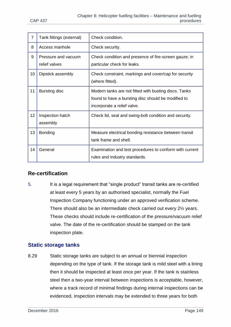
CAP 437 Chapter 8: Helicopter fuelling facilities – Maintenance and fuelling
procedures
December 2016 Page 149
7 Tank fittings (external) Check condition.
8 Access manhole Check security.
9 Pressure and vacuum
relief valves
Check condition and presence of fire-screen gauze; in
particular check for leaks.
10 Dipstick assembly Check constraint, markings and cover/cap for security
(where fitted).
11 Bursting disc Modern tanks are not fitted with busting discs. Tanks
found to have a bursting disc should be modified to
incorporate a relief valve.
12 Inspection hatch
assembly
Check lid, seal and swing-bolt condition and security.
13 Bonding Measure electrical bonding resistance between transit
tank frame and shell.
14 General Examination and test procedures to conform with current
rules and industry standards.
Re-certification
5. It is a legal requirement that “single product” transit tanks are re-certified
at least every 5 years by an authorised specialist, normally the Fuel
Inspection Company functioning under an approved verification scheme.
There should also be an intermediate check carried out every 2½ years.
These checks should include re-certification of the pressure/vacuum relief
valve. The date of the re-certification should be stamped on the tank
inspection plate.
Static storage tanks
8.29 Static storage tanks are subject to an annual or biennial inspection
depending on the type of tank. If the storage tank is mild steel with a lining
then it should be inspected at least once per year. If the tank is stainless
steel then a two-year interval between inspections is acceptable, however,
where a track record of minimal findings during internal inspections can be
evidenced, inspection intervals may be extended to three years for both
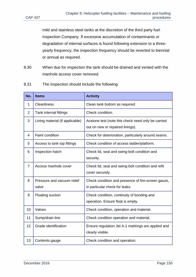
CAP 437 Chapter 8: Helicopter fuelling facilities – Maintenance and fuelling
procedures
December 2016 Page 150
mild and stainless steel tanks at the discretion of the third party fuel
Inspection Company. If excessive accumulation of contaminants or
degradation of internal surfaces is found following extension to a three-
yearly frequency, the inspection frequency should be reverted to biennial
or annual as required.
8.30 When due for inspection the tank should be drained and vented with the
manhole access cover removed.
8.31 The inspection should include the following:
No. Items Activity
1 Cleanliness Clean tank bottom as required.
2 Tank internal fittings Check condition.
3 Lining material (if applicable) Acetone test (note this check need only be carried
out on new or repaired linings).
4 Paint condition Check for deterioration, particularly around seams.
5 Access to tank top fittings Check condition of access ladder/platform.
6 Inspection hatch Check lid, seal and swing-bolt condition and
security.
7 Access manhole cover Check lid, seal and swing-bolt condition and refit
cover securely.
8 Pressure and vacuum relief
valve
Check condition and presence of fire-screen gauze,
in particular check for leaks.
9 Floating suction Check condition, continuity of bonding and
operation. Ensure float is empty.
10 Valves Check condition, operation and material.
11 Sump/drain line Check condition operation and material.
12 Grade identification Ensure regulation Jet A-1 markings are applied and
clearly visible.
13 Contents gauge Check condition and operation.

CAP 437 Chapter 8: Helicopter fuelling facilities – Maintenance and fuelling
procedures
December 2016 Page 151
14 Bonding Measure electrical bonding resistance between tank
and system pipework.
Delivery systems
8.32 The offshore delivery system should normally be inspected every three
months by a fuel inspection company, contracted by the offshore asset
owner or duty holder to inspect and certify the system is fit for uplifting fuel
by the helicopter operator.
NOTE: Inspection in this context is not to be confused with Auditing. It is physical
intervention / trades supervision by a fully trained and competent engineer for
determining condition and replacement of key system components, prior to
certifying the system is fit for purpose.
8.33 The function of fuel inspection is twofold; firstly, it allows necessary
scheduled invasive and specialist work-scopes to be carried out by an
approved engineer, and secondly, it provides system certification on
completion of a successful inspection.
8.34 No system should exceed four months between successive inspections
and certification may be withdrawn if the system is not maintained in
accordance with the requirements noted below.
8.35 The system should be subject to daily and weekly checks by offshore
fuelling personnel to ensure sustained operability and satisfactory fuel
quality.
Daily checks
1. The following checks should be carried out each day and is the
responsibility of the HLO, although tasks may be delegated to another
competent person.

CAP 437 Chapter 8: Helicopter fuelling facilities – Maintenance and fuelling
procedures
December 2016 Page 152
Items Activity
1 Filter water separator
and fuel filter monitor
Drain the fuel from the sump/sample line until it is clear. The
sample taken should be checked and retained as noted in
paragraph 8.20.
NOTE: This check excludes the transfer filter which
should be checked weekly or prior to use,
whichever is the sooner. This can only be carried
out when fuel is being transferred.
2 Transit tank/storage
tank
A fuel sample should be drawn from each compartment of
the transit tank/storage tank (as applicable) and checked for
quality as noted in paragraphs 8.13 and 8.16.
3 Floating suction The floating suction assembly should be checked for
buoyancy and freedom of movement.
4 Delivery hose end
(refuelling nozzle)
A sample should be drawn from the hose end and checked
for quality as noted in paragraphs 8.13 and 8.16.
5 General system
checks
Check for signs of leakage from the system.
Ensure that all dispensing equipment is stowed inside the
dispensing cabinet with the door closed for protection from
the elements when not in use.
6 Complete
documentation
Daily checks should be recorded on the ‘Daily Storage
Check’ quality control documentation.
Weekly checks
2. In addition to the daily checks specified in paragraph 1 above the
following checks should be carried out each week and is the responsibility
of the HLO, although tasks may be delegated to another competent
person.
Items Activity
1 Transit tanks Carry out weekly tank checks as detailed in paragraph 8.28.3.

CAP 437 Chapter 8: Helicopter fuelling facilities – Maintenance and fuelling
procedures
December 2016 Page 153
2 Suction hose
and hose
coupling
For EN ISO 1825 rubber hoses:
Lay out straight to allow the hose to be examined along its
length for damage i.e. “soft spots”, bulges, blistering, cuts,
abrasions, kinks or crushing. Light surface damage is
acceptable, however, no white canvas braiding should be
visible through the skin of the hose.
Check hose end clamps for security.
For B-Flex annular convoluted hoses:
Check hose has not been coiled too tightly.
Check condition of outer protective cover where fitted.
Feel along hose length checking for crush damage.
General checks:
Check complete assembly for any indication of leakage.
Check correct operation of hose coupling.
Check captive dust plug is present.
3 Static storage
tanks
Check all tank top fittings are in place, clean and all dust caps are
fitted.
Check that valves are closed and inspection hatches tightened
down.
4 Pump
skid/cabinet
Check pump bearings are adequately greased.
For air motor driven systems:
Ensure air-line lubricators are adequately topped up with
suitable oil and drain air- line water traps.
For electric motor driven systems:
Check pump drive gearbox oil level and top up as required.
5 Differential
pressure
gauges
For delivery filter vessels:
Obtain weekly differential pressure readings for each vessel
during refuelling under full flow conditions. If no refuel has
taken place during any given week, a sufficient quantity of
fuel should be run off into a drum at full flow to allow
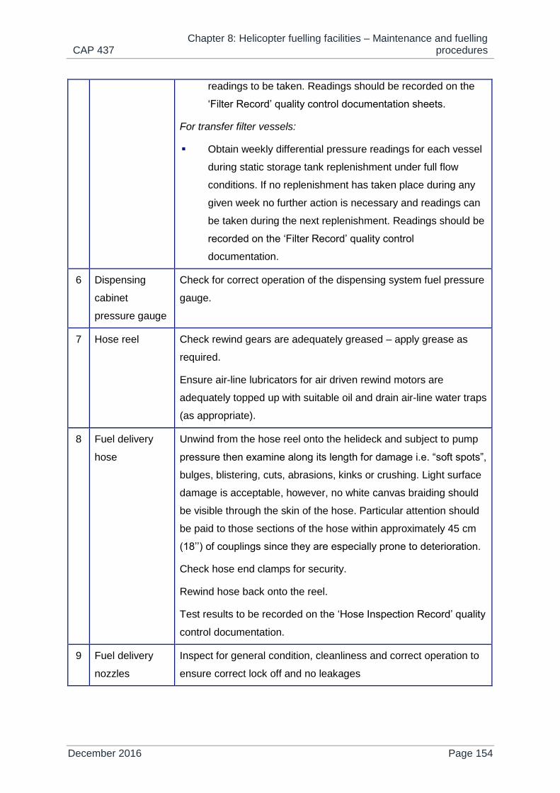
CAP 437 Chapter 8: Helicopter fuelling facilities – Maintenance and fuelling
procedures
December 2016 Page 154
readings to be taken. Readings should be recorded on the
‘Filter Record’ quality control documentation sheets.
For transfer filter vessels:
Obtain weekly differential pressure readings for each vessel
during static storage tank replenishment under full flow
conditions. If no replenishment has taken place during any
given week no further action is necessary and readings can
be taken during the next replenishment. Readings should be
recorded on the ‘Filter Record’ quality control
documentation.
6 Dispensing
cabinet
pressure gauge
Check for correct operation of the dispensing system fuel pressure
gauge.
7 Hose reel Check rewind gears are adequately greased – apply grease as
required.
Ensure air-line lubricators for air driven rewind motors are
adequately topped up with suitable oil and drain air-line water traps
(as appropriate).
8 Fuel delivery
hose
Unwind from the hose reel onto the helideck and subject to pump
pressure then examine along its length for damage i.e. “soft spots”,
bulges, blistering, cuts, abrasions, kinks or crushing. Light surface
damage is acceptable, however, no white canvas braiding should
be visible through the skin of the hose. Particular attention should
be paid to those sections of the hose within approximately 45 cm
(18’’) of couplings since they are especially prone to deterioration.
Check hose end clamps for security.
Rewind hose back onto the reel.
Test results to be recorded on the ‘Hose Inspection Record’ quality
control documentation.
9 Fuel delivery
nozzles
Inspect for general condition, cleanliness and correct operation to
ensure correct lock off and no leakages
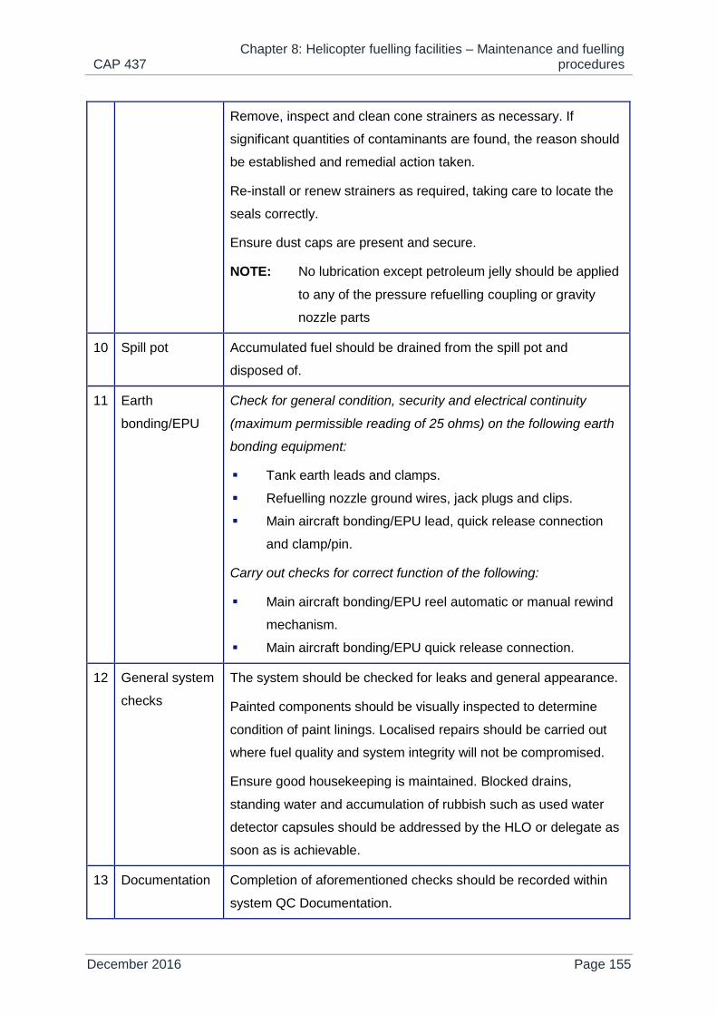
CAP 437 Chapter 8: Helicopter fuelling facilities – Maintenance and fuelling
procedures
December 2016 Page 155
Remove, inspect and clean cone strainers as necessary. If
significant quantities of contaminants are found, the reason should
be established and remedial action taken.
Re-install or renew strainers as required, taking care to locate the
seals correctly.
Ensure dust caps are present and secure.
NOTE: No lubrication except petroleum jelly should be applied
to any of the pressure refuelling coupling or gravity
nozzle parts
10 Spill pot Accumulated fuel should be drained from the spill pot and
disposed of.
11 Earth
bonding/EPU
Check for general condition, security and electrical continuity
(maximum permissible reading of 25 ohms) on the following earth
bonding equipment:
Tank earth leads and clamps.
Refuelling nozzle ground wires, jack plugs and clips.
Main aircraft bonding/EPU lead, quick release connection
and clamp/pin.
Carry out checks for correct function of the following:
Main aircraft bonding/EPU reel automatic or manual rewind
mechanism.
Main aircraft bonding/EPU quick release connection.
12 General system
checks
The system should be checked for leaks and general appearance.
Painted components should be visually inspected to determine
condition of paint linings. Localised repairs should be carried out
where fuel quality and system integrity will not be compromised.
Ensure good housekeeping is maintained. Blocked drains,
standing water and accumulation of rubbish such as used water
detector capsules should be addressed by the HLO or delegate as
soon as is achievable.
13 Documentation Completion of aforementioned checks should be recorded within
system QC Documentation.

CAP 437 Chapter 8: Helicopter fuelling facilities – Maintenance and fuelling
procedures
December 2016 Page 156
Three-monthly inspection
3. A three-monthly inspection is the foundation on which the more in-depth
six-monthly and annual inspection work scopes are based. Three-monthly
inspection work scopes should only be carried out by an authorised Fuel
Inspector and will vary dependent on the particular installation and fuel
system set up.
NOTE 1: An authorised Fuel Inspector is defined as an individual that is independent from
the business unit procuring the inspection service. Inspectors should be
technically qualified and competent and be able to demonstrate they have
relevant experience on the offshore refuelling systems, components and
equipment subjected to examination and verification.
NOTE 2: On some installations, duty holders may require specific work activities to be
undertaken by an on-board maintenance team member (e.g. an electrician and /
or mechanic) as part of the maintenance management plan. In such cases, the
work undertaken by the duty holder should not include activities for breaking into
system fuel containment, without receipt of written approval from the authorised /
certifying Fuel Inspection Company. Any work done may additionally require
inspection and verification following completion.
The following checklist is included as a general guide only, but should
cover most equipment scenarios. Additional items may be included when
considered appropriate.
Items Activity
1 Transit
tanks
Carry out weekly tank checks as detailed in paragraph 8.28.3.
2 Suction
hose and
hose
coupling
For EN ISO 1825 rubber hoses:
Lay out straight to allow the hose to be examined along its length
for damage i.e. “soft spots”, bulges, blistering, cuts, abrasions,
kinks or crushing. Light surface damage is acceptable, however,
no white canvas braiding should be visible through the skin of
the hose.

CAP 437 Chapter 8: Helicopter fuelling facilities – Maintenance and fuelling
procedures
December 2016 Page 157
Check hose end clamps for security.
For B-Flex annular convoluted hoses:
Check hose has not been coiled too tightly.
Check condition of outer protective cover where fitted.
Feel along hose length checking for crush damage.
General checks:
Check complete assembly for any indication of leakage.
Check correct operation of hose coupling.
Check captive dust plug is present.
3 Static
storage
tanks
Check all tank top fittings are in place, clean and all dust caps are
fitted.
Check that valves are closed and inspection hatches tightened down.
4 Pump
skid/cabinet
Remove, clean and inspect Y-strainer baskets. Where a track record of
minimal findings during previous inspections can be evidenced,
inspection intervals may be extended to six months at the discretion of
the third party fuel inspection company. If an excessive accumulation of
contaminants are found following extension to a six-monthly frequency,
the inspection frequency should be reverted to three-monthly as
required.
Check pump bearings are adequately greased.
For air motor driven systems:
Ensure air line lubricators are adequately topped up with suitable
oil and drain air line water traps.
Check air line lubricator drip feed rate is set correctly.
For electric motor driven systems:
Check pump drive gearbox oil level and top up as required.
5 All filtration
units (e.g.
transfer
and
delivery
Check vessels for condition, security of fittings, evidence of leakage
and correct product identification labels.
Obtain a fuel sample from each filtration unit and perform fuel quality
checks as noted in paragraphs 8.13 and 8.16. Note results of the
sample checks on system QC documentation.

CAP 437 Chapter 8: Helicopter fuelling facilities – Maintenance and fuelling
procedures
December 2016 Page 158
filter
vessels)
If consistently unacceptable samples are evident during the three-
monthly check it could indicate the presence of bacteriological growth
in the vessel. This will require the following action to be taken:
Open the filter vessel and inspect for surfactants, bacteriological
presence, mechanical damage and condition of lining (as
applicable).
Clean out any sediment and carry out a water test on the water
separator element (as applicable).
Inspect the coalescer/monitor elements (as applicable) and
renew as necessary.
Reassemble and repeat testing.
6 Differential
pressure
gauges
Check condition and security of gauges.
Check for correct operation during functional testing and check for full
scale deflection and return to ‘zero’ where gauges have been set up
with test valves.
For delivery filter vessels:
Obtain weekly differential pressure readings for each vessel
during refuelling under full flow conditions. If no refuel has taken
place during any given week, a sufficient quantity of fuel should
be run off into a drum at full flow to allow readings to be taken.
Readings should be recorded on the ‘Filter Record’ quality
control documentation sheets.
For transfer filter vessels:
Obtain weekly differential pressure readings for each vessel
during static storage tank replenishment under full flow
conditions. If no replenishment has taken place during any given
week no further action is necessary and readings can be taken
during the next replenishment. Readings should be recorded on
the ‘Filter Record’ quality control documentation.
7 Automatic
air
eliminators
Prime and check for correct operation of all installed air eliminators. If a
manual air vent valve is fitted, replace it with an automatic type.

CAP 437 Chapter 8: Helicopter fuelling facilities – Maintenance and fuelling
procedures
December 2016 Page 159
8 System
pressure
relief valves
Visually check for condition and note certification frequency and due
dates on the system inspection report.
9 Dispensing
cabinet
pressure
gauge
Check for correct operation of the dispensing system fuel pressure
gauge.
10 Hose reel Ensure reel rewind mechanism operates correctly by testing operation
using powered and manual rewinds (as appropriate).
Check bearings and rewind gears are adequately greased – apply
grease as required.
Ensure air-line lubricators for air driven rewind motors are adequately
topped up with suitable oil and drain air-line water traps (as
appropriate).
Check air-line lubricator drip feed rate is set correctly (as appropriate).
Inspect inlet swivel and swan neck hose connection for condition.
11 Fuel
delivery
hose
Unwind from the hose reel onto the helideck and subject to pump
pressure then examine along its length for damage i.e. “soft spots”,
bulges, blistering, cuts, abrasions, kinks or crushing. Light surface
damage is acceptable; however, no white canvas braiding should be
visible through the skin of the hose. Particular attention should be paid
to those sections of the hose within approximately 45 cm (18’’) of
couplings since they are especially prone to deterioration.
Check hose end clamps for security.
Rewind hose back onto the reel.
Test results to be recorded on the ‘Hose Inspection Record’ quality
control documentation.
12 Fuel
delivery
nozzles
Inspect for general condition, cleanliness and correct operation to
ensure correct lock off and no leakages.
Remove, inspect and clean cone strainers as necessary. If significant
quantities of contaminants are found, the reason should be established
and remedial action taken.

CAP 437 Chapter 8: Helicopter fuelling facilities – Maintenance and fuelling
procedures
December 2016 Page 160
Re-install or renew strainers as required, taking care to locate the seals
correctly.
Ensure dust caps are present and secure.
NOTE: No lubrication except petroleum jelly should be applied to
any of the pressure refuelling coupling or gravity nozzle
parts.
13 Spill pot Accumulated fuel should be drained from the spill pot and disposed of.
14 Earth
bonding/
EPU
Check for general condition, security and electrical continuity
(maximum permissible reading of 25 ohms) on the following earth
bonding equipment:
Tank earth leads and clamps.
Refuelling nozzle ground wires, jack plugs and clips.
Main aircraft bonding/EPU lead, quick release connection and
clamp/pin.
Carry out checks for correct function of the following:
Main aircraft bonding/EPU reel automatic or manual rewind
mechanism.
Main aircraft bonding/EPU quick release connection.
15 General
system
checks
The system should be checked for leaks and general appearance.
Painted components should be visually inspected to determine
condition of paint linings. Localised repairs should be carried out where
fuel quality and system integrity will not be compromised.
Ensure good housekeeping is maintained. Blocked drains, standing
water and accumulation of rubbish such as used water detector
capsules should be addressed by the HLO or delegate as soon as is
achievable.
16 Documenta
tion
Completion of aforementioned checks should be recorded within
system QC Documentation.
Six-monthly inspection
4. Six-monthly inspections should be carried out only by an authorised Fuel
Inspector. The content of a six-monthly inspection should include all of the

CAP 437 Chapter 8: Helicopter fuelling facilities – Maintenance and fuelling
procedures
December 2016 Page 161
three-monthly inspection checks detailed in paragraph c above and, in
addition, should include the following items:
NOTE: On some installations, duty holders may require specific work activities to be
undertaken by an on-board maintenance team member (e.g. an electrician and /
or mechanic) as part of the maintenance management plan. In such cases, work
undertaken by the duty holder should not include activities for breaking into
system fuel containment, without receipt of written approval from the authorised /
certifying Fuel Inspection Company. Any work done may additionally require
inspection and verification following completion.
Items Activity
1 Pump
skid/cabinet
Check coupling between motor and pump for wear and signs of
misalignment.
Refer to refuel system supplier / pump manufacturer’s
recommended maintenance schedule for additional items.
For electric motor driven systems:
All electrical circuits to be checked by a qualified electrician.
2 Interconnecting
pipework
Check for clear fuel grade identification labelling in accordance with
EI 1542.
3 Flow Meter Lubricate the meter register head, drive and calibration gears with
petroleum jelly.
Remove, inspect and clean strainer basket as necessary. If
significant quantities of contaminants are found, the reason should
be established and remedial action taken.
Re-install or renew strainer as required, taking care to locate the
seals correctly.
4 Hose reel Check tension on chain drive and adjust if necessary.
5 Documentation Completion of aforementioned checks should be recorded within the
QC Documentation.
6 Pump
skid/cabinet
Check coupling between motor and pump for wear and signs of
misalignment.
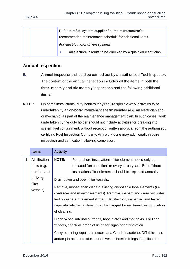
CAP 437 Chapter 8: Helicopter fuelling facilities – Maintenance and fuelling
procedures
December 2016 Page 162
Refer to refuel system supplier / pump manufacturer’s
recommended maintenance schedule for additional items.
For electric motor driven systems:
All electrical circuits to be checked by a qualified electrician.
Annual inspection
5. Annual inspections should be carried out by an authorised Fuel Inspector.
The content of the annual inspection includes all the items in both the
three-monthly and six-monthly inspections and the following additional
items:
NOTE: On some installations, duty holders may require specific work activities to be
undertaken by an on-board maintenance team member (e.g. an electrician and /
or mechanic) as part of the maintenance management plan. In such cases, work
undertaken by the duty holder should not include activities for breaking into
system fuel containment, without receipt of written approval from the authorised /
certifying Fuel Inspection Company. Any work done may additionally require
inspection and verification following completion.
Items Activity
1 All filtration
units (e.g.
transfer and
delivery
filter
vessels)
NOTE: For onshore installations, filter elements need only be
replaced “on condition” or every three years. For offshore
installations filter elements should be replaced annually
Drain down and open filter vessels.
Remove, inspect then discard existing disposable type elements (i.e.
coalescer and monitor elements). Remove, inspect and carry out water
test on separator element if fitted. Satisfactorily inspected and tested
separator elements should then be bagged for re-fitment on completion
of cleaning.
Clean vessel internal surfaces, base plates and manifolds. For lined
vessels, check all areas of lining for signs of deterioration.
Carry out lining repairs as necessary. Conduct acetone, DfT thickness
and/or pin hole detection test on vessel interior linings if applicable.

CAP 437 Chapter 8: Helicopter fuelling facilities – Maintenance and fuelling
procedures
December 2016 Page 163
NOTE: These need only be carried out to check for correct curing
when lining is new or has been repaired.
Fit new disposable elements.
Fit tested separator element or renew as required (if fitted).
Fit new head gasket / seal, close up the vessel and tighten the head
securing bolts.
Mark the filter body with the dates of the filter element change.
2 Delivery
hose
Ascertain when the hose was fitted from system records.
Delivery hoses should be pressure tested and recertified (ISO 1825)
every two years. However, for operational expediency, duty holders
may elect to replace the hose at the prescribed interval or earlier if any
defects are found which cannot be repaired.
In the absence of facilities for offshore testing, a removed hose should
be tested and re-certified onshore.
The hose will have a ten-year life from date of manufacture.
Miscellaneous inspection frequency
6. Inspection of some items of equipment within the fuelling system fall out-
with standard frequencies. This may be because of individual component
manufacturer’s recommendations or over-riding platform or vessel
standards as examples. Generally, where there is a conflict in inspection
frequency, it is preferred that the more stringent standard is adopted. The
inspection scopes listed below should be carried out by an authorised
Fuel Inspector:
Items Activity
1 Pressure relief
valves
Change-out or recertification frequency for relief valves fitted to filter
vessels, static storage tanks, pipework or other equipment is often
dictated by installation specific standards.
Relief valves fitted to transit tanks are always managed under IMDG
test requirements, i.e. 2½ year frequency.

CAP 437 Chapter 8: Helicopter fuelling facilities – Maintenance and fuelling
procedures
December 2016 Page 164
Relief valves may be included in a general installation relief valve
register but should only be changed out by an authorised third party
Fuel Inspector.
Wherever possible relief valve change-out should be aligned with
scheduled invasive work on the equipment to which it is fitted (e.g.
filter change or static storage tank internal inspection).
2 Flow meter Flow meters may be included in a general installation
instrumentation register but should only be changed out by an
authorised Fuel Inspector.
The flow meter calibration frequency should be in accordance with
the manufacturer recommendations. This may be based on elapsed
time or throughput.
If there is evidence of inaccuracy such as metered quantities not
aligning with aircraft instrument readings, investigation and / or
rectification / calibration may need to be completed out-with the
manufacturer recommendations.
3 Gauges and
instrumentation
Pressure and differential pressure gauge calibration or replacement
frequencies may be based on gauge type, criticality, manufacturer
or operator requirements.
System breakdown
8.36 In the event of a system breakdown, as a general rule, before carrying out
‘in-house’ repairs on fuelling system equipment, the HLO or his delegate
should consult with the issuer of the current system certification to discuss
the symptoms of the problem and to seek advice and permission before
carrying out any work in order to maintain third party certification of the
system. Some work scopes will be permissible following a brief
discussion, others will be permissible if carried out by following written
instructions or procedures and still others will not be permissible as an in-
house repair at all, requiring the mobilisation of an authorised Fuel
Inspector.
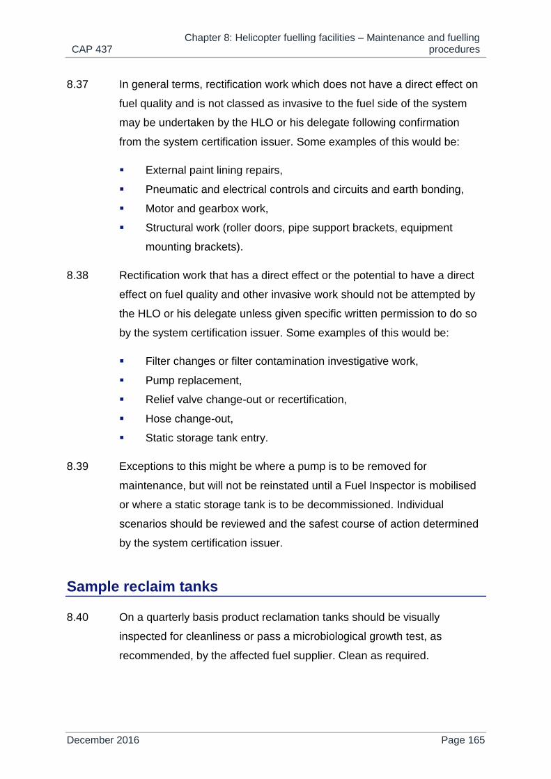
CAP 437 Chapter 8: Helicopter fuelling facilities – Maintenance and fuelling
procedures
December 2016 Page 165
8.37 In general terms, rectification work which does not have a direct effect on
fuel quality and is not classed as invasive to the fuel side of the system
may be undertaken by the HLO or his delegate following confirmation
from the system certification issuer. Some examples of this would be:
External paint lining repairs,
Pneumatic and electrical controls and circuits and earth bonding,
Motor and gearbox work,
Structural work (roller doors, pipe support brackets, equipment
mounting brackets).
8.38 Rectification work that has a direct effect or the potential to have a direct
effect on fuel quality and other invasive work should not be attempted by
the HLO or his delegate unless given specific written permission to do so
by the system certification issuer. Some examples of this would be:
Filter changes or filter contamination investigative work,
Pump replacement,
Relief valve change-out or recertification,
Hose change-out,
Static storage tank entry.
8.39 Exceptions to this might be where a pump is to be removed for
maintenance, but will not be reinstated until a Fuel Inspector is mobilised
or where a static storage tank is to be decommissioned. Individual
scenarios should be reviewed and the safest course of action determined
by the system certification issuer.
Sample reclaim tanks
8.40 On a quarterly basis product reclamation tanks should be visually
inspected for cleanliness or pass a microbiological growth test, as
recommended, by the affected fuel supplier. Clean as required.

CAP 437 Chapter 8: Helicopter fuelling facilities – Maintenance and fuelling
procedures
December 2016 Page 166
Transit tanks
8.41 On a quarterly basis product reclamation tanks should be visually
inspected for cleanliness or pass a microbiological growth test, as
recommended, by the affected fuel supplier. Clean as required.
Filling of transit tanks
8.42 A ‘trip inspection’ should be carried out as specified in paragraph 8.28 on
return to the tank filling depot. The tank should then be dipped to
ascertain the quantity of fuel in the tank in order to calculate the volume of
fuel required to fill the tank. Assuming the tank is in serviceable condition,
the following actions should then be completed:
1) Draw fuel from transit tank sample line and discard until the samples
appear free from water and solid contaminants.
2) Carry out fuel quality check as noted in paragraphs 8.13 and 8.16.
3) Once satisfied that the fuel is free from free and dissolved water,
draw off sufficient fuel to measure its specific gravity with a clean
hydrometer. The fuel temperature should also be noted in order to
correct the measured specific gravity to a relative density (RD) using
a correction chart.
4) The RD of the fuel sample taken from the transit tank should be
compared with that of the previous recorded RD after the last tank
filling. The RD of the previous batch of fuel should be taken from the
previous release note or from the label on the retained sample. If the
difference in relative densities exceeds 3.0kg/m3 the contents of the
transit tank may have been contaminated with some other product
refilling should not take place and the contents of the tank may need
to be disposed of.
5) Assuming the RD of the returned fuel is within specification, connect
the bonding wire to the transit tank then connect the delivery hose
coupling to the tank filling point and start the transfer pump to fill the
tank. When the meter register head indicates that the required
quantity of fuel has been transferred, stop the transfer pump, remove

CAP 437 Chapter 8: Helicopter fuelling facilities – Maintenance and fuelling
procedures
December 2016 Page 167
the coupling from the tank and then remove the bonding connection.
The dust cap should then be replaced on the filling point.
6) Leave the tank to settle for ten minutes. A further sample should be
drawn from the tank once it has been filled. The sample should be
subjected to a RD check following the same process given in
paragraph 4 and the density should be within 3.0kg/m3 of the
composite RD of the bulk tank contents and transit tank residue. This
sample should be transferred to a retention can which should be
labelled with the tank number, the fuel batch number, date of filling
and measured RD. The sample should then be retained safely until
the tank is offered again for refilling in order to continue the fuel
traceability. This fuel sample will be required as a proof of fuel quality
in the event of an aircraft incident where fuel may be considered to
be a causal factor.
7) The tank should then be sealed to prevent tampering and a release
note completed with all the required particulars; special attention
should be paid that the correct grade of fuel is included on this
release note.
8) A copy of the release note should be secured in the tank document
container and a further copy retained for reference.
Receipt of transit tanks offshore
8.43 Transit tanks transported offshore are often exposed to sea spray and
harsh weather conditions on supply vessels and this could potentially
cause ingress of water into the fuel. It is strongly recommended that fuel
sampling is carried out as soon as the appropriate settling time has
elapsed or at least within 24 hours of the tank being placed into a bunded
storage area on the installation or vessel. Settling times are one hour per
foot depth of fuel in the tank.
8.44 The following procedure should then be followed:
1) Check transit tank seals are still intact.

CAP 437 Chapter 8: Helicopter fuelling facilities – Maintenance and fuelling
procedures
December 2016 Page 168
2) Check transit tank fuel grade markings match the fuel grade stated
on the fuel release certificate.
3) Check tank shell for damage, particularly around welded seams.
4) Check fuel release certificate for the following:
a) correct grade,
b) quantity,
c) batch number.
d) date filled
e) certified free from solid contaminants and water; and
f) signed by authorised product inspector.
5) Take fuel samples from the transit tank and discard until the samples
appear free from water as indicated in paragraph 8.13.
Decanting from transit tanks to static storage
8.45 Before commencing any transfer of fuel it is necessary to check the static
storage tank fuel level using a dipstick, dip tape or level gauge to ensure
that the contents of the transit tank can be accommodated.
8.46 The transit tank should have had sufficient time to settle once positioned
correctly for the transfer operation. Settling times are one hour per foot
depth of fuel in the tank.
8.47 Static storage tanks equipped with a floating suction device need at least
one hour for settling time and tanks without floating suction should be left
for a period in hours approximately equal to the depth of fuel in feet.
8.48 The following procedure should then be followed:
1) Connect an earth bonding lead to the transit tank.
2) Carry out checks for fuel quality as described in paragraph 8.13.
3) Once a satisfactory sample has been obtained, the suction hose
should be connected to the transit tank discharge point and the tank
foot valve should be opened.
4) With the system valves set up to supply fuel from the transit tank to
the transfer pump and on to the transfer filter vessel, the transfer
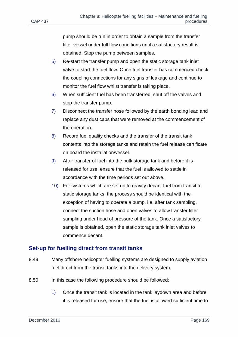
CAP 437 Chapter 8: Helicopter fuelling facilities – Maintenance and fuelling
procedures
December 2016 Page 169
pump should be run in order to obtain a sample from the transfer
filter vessel under full flow conditions until a satisfactory result is
obtained. Stop the pump between samples.
5) Re-start the transfer pump and open the static storage tank inlet
valve to start the fuel flow. Once fuel transfer has commenced check
the coupling connections for any signs of leakage and continue to
monitor the fuel flow whilst transfer is taking place.
6) When sufficient fuel has been transferred, shut off the valves and
stop the transfer pump.
7) Disconnect the transfer hose followed by the earth bonding lead and
replace any dust caps that were removed at the commencement of
the operation.
8) Record fuel quality checks and the transfer of the transit tank
contents into the storage tanks and retain the fuel release certificate
on board the installation/vessel.
9) After transfer of fuel into the bulk storage tank and before it is
released for use, ensure that the fuel is allowed to settle in
accordance with the time periods set out above.
10) For systems which are set up to gravity decant fuel from transit to
static storage tanks, the process should be identical with the
exception of having to operate a pump, i.e. after tank sampling,
connect the suction hose and open valves to allow transfer filter
sampling under head of pressure of the tank. Once a satisfactory
sample is obtained, open the static storage tank inlet valves to
commence decant.
Set-up for fuelling direct from transit tanks
8.49 Many offshore helicopter fuelling systems are designed to supply aviation
fuel direct from the transit tanks into the delivery system.
8.50 In this case the following procedure should be followed:
1) Once the transit tank is located in the tank laydown area and before
it is released for use, ensure that the fuel is allowed sufficient time to

CAP 437 Chapter 8: Helicopter fuelling facilities – Maintenance and fuelling
procedures
December 2016 Page 170
settle in accordance with the following time periods. Settling times
are one hour per foot depth of fuel in the tank.
2) Connect an earth bonding lead to the transit tank.
3) Take fuel samples from the transit tank and discard until the samples
appear free from water and solid contaminants.
4) Carry out checks for fuel quality as described in paragraph 8.13.
5) Once a satisfactory sample has been obtained the suction hose
should be connected to the transit tank discharge point and the tank
foot valve should be opened.
6) With the system valves set up to supply fuel from the transit tank to
the delivery pump and on to the delivery filter vessels, the delivery
pump should be run in order obtain a sample from the delivery filter
water separator and, fuel filter monitor or combined three-stage
vessel followed by the hose end until a satisfactory result is obtained
from each. Stop the pump between samples. Record fuel quality
checks, sample quantities taken and retain the fuel release
certificate on board the installation/vessel.
7) With the system valves set up to supply fuel from the transit tank to
the delivery pump and on to the delivery filter vessels, the delivery
pump should be run in order obtain a sample from the delivery filter
water separator and, fuel filter monitor or combined three-stage
vessel followed by the hose end until a satisfactory result is obtained
from each. Stop the pump between samples. Record fuel quality
checks, sample quantities taken and retain the fuel release
certificate on board the installation/vessel.
8) The system is now ready for fuelling an aircraft.
Set-up for fuelling from static storage tanks
8.51 The process for refuelling from static storage tanks should be identical to
that of refuelling from transit tanks with the exception of setting up system
valves to route fuel from the static storage tank to the pumps.
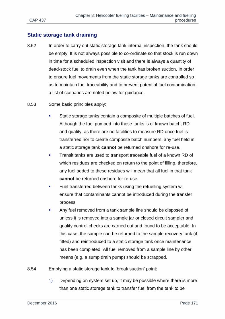
CAP 437 Chapter 8: Helicopter fuelling facilities – Maintenance and fuelling
procedures
December 2016 Page 171
Static storage tank draining
8.52 In order to carry out static storage tank internal inspection, the tank should
be empty. It is not always possible to co-ordinate so that stock is run down
in time for a scheduled inspection visit and there is always a quantity of
dead-stock fuel to drain even when the tank has broken suction. In order
to ensure fuel movements from the static storage tanks are controlled so
as to maintain fuel traceability and to prevent potential fuel contamination,
a list of scenarios are noted below for guidance.
8.53 Some basic principles apply:
Static storage tanks contain a composite of multiple batches of fuel.
Although the fuel pumped into these tanks is of known batch, RD
and quality, as there are no facilities to measure RD once fuel is
transferred nor to create composite batch numbers, any fuel held in
a static storage tank cannot be returned onshore for re-use.
Transit tanks are used to transport traceable fuel of a known RD of
which residues are checked on return to the point of filling, therefore,
any fuel added to these residues will mean that all fuel in that tank
cannot be returned onshore for re-use.
Fuel transferred between tanks using the refuelling system will
ensure that contaminants cannot be introduced during the transfer
process.
Any fuel removed from a tank sample line should be disposed of
unless it is removed into a sample jar or closed circuit sampler and
quality control checks are carried out and found to be acceptable. In
this case, the sample can be returned to the sample recovery tank (if
fitted) and reintroduced to a static storage tank once maintenance
has been completed. All fuel removed from a sample line by other
means (e.g. a sump drain pump) should be scrapped.
8.54 Emptying a static storage tank to ‘break suction’ point:
1) Depending on system set up, it may be possible where there is more
than one static storage tank to transfer fuel from the tank to be

CAP 437 Chapter 8: Helicopter fuelling facilities – Maintenance and fuelling
procedures
December 2016 Page 172
inspected into another storage tank by orientating the valves to draw
from one tank and pump through the transfer vessel into the other
tank.
2) If fuel cannot be transferred from one storage tank to another and it
is possible to locate a transportable tank on the helideck or within
reach of the fuel delivery hose, fuel can be pumped to a
transportable tank using a crossover connection to connect the
delivery system to the tank fill connection as if refuelling an aircraft.
The tank should be earth bonded prior to pumping fuel into it. This
fuel can then be sampled and transferred back to a static storage
tank once maintenance has been completed, however, fuel residues
after breaking suction cannot be returned onshore for re-use.
Residues can either be returned onshore for disposal in the tank, or
transferred into a drum or hazardous drain however, the tank should
be adequately labelled as containing scrap fuel and manifested as
such. Additionally, the tank supplier should be informed that the tank
has contained mixed RD fuel and should be cleaned and conditioned
once returned onshore.
3) If fuel cannot be handled as described above in order to control its
quality for re-use, then all fuel in the static storage tank should be
decanted to waste. This can be accomplished using the fuel delivery
system to pump into a waste fuel tank, drums or hazardous drains
until the tank breaks suction. Alternatively, a tank could be drained
by fitting a sump drain pump to the sample line before breaking
suction as described below.
8.55 Emptying static storage tank dead-stock:
1) Dead-stock can be sampled and if satisfactory, decanted into the
sample recovery tank (if fitted) and reintroduced to a static storage
tank once maintenance has been completed, however, this is a long
and laborious process and sample recovery tanks will often not have
sufficient capacity to contain all dead-stock.

CAP 437 Chapter 8: Helicopter fuelling facilities – Maintenance and fuelling
procedures
December 2016 Page 173
2) A sump drain pump (e.g. a 1” air driven diaphragm pump) can be
connected to the static storage sample line end connection and run
to suck all fuel out until the tank is empty. This fuel can be pumped
to a waste fuel tank, drums or hazardous drains.
Long term storage of aviation fuel
8.56 The long term storage of aviation fuel offshore should be discouraged.
Should fuel stocks remain unused offshore for an extended period (i.e. six
months after the filling date) then, prior to use, samples should be drawn
from the tank and sent onshore for laboratory testing to ensure fuel
quality. An alternative course of action is to return the transit tank(s) to an
onshore fuel depot for further action.
Aircraft refuelling
8.57 Refuelling during thunderstorms and significant lightning activity poses
significant risks and should therefore be avoided.
8.58 Always ensure before starting any refuel that the fuel in the static storage
tank or transit tank is properly settled. Refer to paragraph 1.66.1 for
correct settling times.
8.59 Before the commencement of any helicopter refuel, the HLO should be
notified. Unless for specific safety reasons (see 10 below), passengers
should normally be disembarked from the helicopter and should be clear
of the helideck before refuelling commences. The helideck fire team
should be in attendance at all times during any refuelling operation. The
following procedure should then apply:
1) When the aircraft captain is ready and it has been ascertained how
much fuel is required and that the grade of fuel is correct for the
particular aircraft, take a fuel sample from the overwing nozzle or
from the pressure refuelling coupling sample point and carry out a
water detection and fuel quality check in the presence of a flight crew

CAP 437 Chapter 8: Helicopter fuelling facilities – Maintenance and fuelling
procedures
December 2016 Page 174
member (e.g. non-handling pilot) who should witness and
acknowledge that the fuel sample colour and water test is acceptable
and the fuel is clear from sediments. Morning samples are generally
accepted, but a fresh sample may be requested by the pilot. If a
flight crew member does not witness the water detection and fuel
quality checks in progress, the water detection capsule and sample
jar contents should be shown to a flight crew member (e.g. non-
handling pilot) after the checks have been carried out.
NOTE: Only if there is no pressure refuelling coupling sample point should a sample be
drawn from the fuel filter monitor sample point.
2) Run out the earth bonding/EPU lead and attach it to the approved
aircraft bonding point. Next, run out the delivery hose on the helideck
to the aircraft refuelling point.
3) If pressure refuelling, first connect the secondary bonding lead to the
approved aircraft bonding point to bond the refuelling nozzle to the
aircraft, then connect the pressure coupling to the aircraft and
remain adjacent to the fuelling point.
4) If gravity refuelling, first connect the secondary bonding lead to bond
the refuelling nozzle to the aircraft, then open the tank filler and
insert the nozzle and prepare to operate the fuel lever when
signalled to do so by the person in charge of refuelling. Ensure fire
cover is provided next to the filler point in the form of a dry powder
extinguisher.
5) The nominated person in charge of the refuelling (e.g. a Helideck
Assistant - HDA) should operate the system pump switches and
open any necessary valves to start the flow of fuel only when given
clearance by the pilot via the HLO; using correct hand signals. The
HLO should remain in a position whereby he has full view of both the
helicopter refuelling point, pilot (handling) and person operating the
fuel station (e.g. HDA). Ideally refuelling teams should be wearing
listening headsets so that HLO can communicate instantly with both
them and the pilot in the event of an emergency.

CAP 437 Chapter 8: Helicopter fuelling facilities – Maintenance and fuelling
procedures
December 2016 Page 175
6) If any abnormalities are observed during the refuelling the “off”
switch should immediately be operated. When refuelling is complete
or when the pilot signals that tanks are full, the pump should be shut
down and the nozzle handle released.
7) Remove the refuelling nozzle or disconnect the pressure coupling as
appropriate and replace the aircraft filler and nozzle caps. Finally
disconnect the secondary bonding lead. A further fuel sample should
now be taken as in 1 above and a fuel water and quality check
should again be carried out. The process should be witnessed by a
flight crew member or the capsule and fuel sample shown to a flight
crew member on completion of the tests. See also paragraph 8.18
for sample retention requirements.
8) Remove the delivery hose from the helideck and carry out a final
check that the aircraft filler cap is secure, then disconnect the main
bonding lead from the aircraft and check that all equipment is clear
from the proximity of the aircraft. The hose should be rewound onto
its reel.
9) Enter the fuel quantity onto the daily refuelling sheet and obtain the
pilot’s signature for the fuel received.
10) IMPORTANT SAFETY CONSIDERATIONS
If for clear flight and helideck operational safety reasons the aircraft
captain, in consultation with the HLO, has decided that the refuelling
should be carried out with engines and/or rotors running and/or with
passengers embarked, the following additional precautions should
be undertaken:
NOTE: Refuelling (engines and/or rotors running or stopped) should never be
executed while the passengers are embarking or disembarking. The
passengers are either on board in accordance with the precautions listed
below, or they are kept at a safe distance.
a) Constant communications should be maintained between the
flight crew (pilot handling), HLO and the refuelling crew.

CAP 437 Chapter 8: Helicopter fuelling facilities – Maintenance and fuelling
procedures
December 2016 Page 176
b) The HLO should remain in a position whereby he has full view
of both the helicopter refuelling point, pilot (handling) and the
person operating the fuelling installation. Ideally refuel teams
should be wearing listening headsets so that HLO can
communicate instantly with both them and the pilot in the event
of an emergency.
c) The passengers should be briefed by the pilot and HLO on
what actions to take if an incident occurs during refuelling.
d) The emergency exits opposite the refuelling point should be
unobstructed and ready for use (and remain open, weather
permitting). Doors on the refuelling side of the helicopter should
remain closed.
NOTE: Unless the Rotorcraft Flight Manual (RFM) gives other safety instructions.
e) Passengers’ seatbelts should be undone.
f) At least one competent HDA should be positioned ready to
supervise disembarkation in the event of an emergency.
g) Provision should be made for safe and rapid evacuation as
directed by competent helideck team personnel (HDAs). The
area beneath the emergency exits should be kept clear.
NOTE: If the presence of fuel vapour is detected inside the helicopter, or any other
hazard arises during refuelling, fuelling should be stopped immediately.
Quality control documentation
8.60 Recording of aviation refuelling system/component manufacture, routine
maintenance and rectification, testing, fuel transfer history and aircraft
refuelling, etc. should be completed on official company documentation.
This documentation is normally provided by the helicopter operators
and/or specialist fuel suppliers and system maintainers. As a minimum,
the documentation used should comprise:
Fuel Release Certificate;

CAP 437 Chapter 8: Helicopter fuelling facilities – Maintenance and fuelling
procedures
December 2016 Page 177
record of transit tank receipt;
daily and weekly serviceability report;
daily storage checks;
differential pressure record;
hose inspection and nozzle filters test record;
storage tank checks before and after replenishment;
fuel system maintenance record;
tank inspection and cleaning record; and
fuelling daily log sheet.
8.61 All helifuel related QA documentation should be checked for
completeness annually, during an independent inspection or audit. This
check should also include helideck team access to CAP 437 Chapters 7
and 8 (latest edition).

CAP 437 Chapter 9: Helicopter landing areas on vessels
December 2016 Page 178
Chapter 9
Helicopter landing areas on vessels
Vessels supporting offshore mineral workings and specific standards for landing areas on merchant vessels
9.1 Helidecks on vessels used in support of the offshore oil and gas industry
should be designed to comply with the requirements of the preceding
chapters of this publication.
9.2 The ICS has published a ‘Guide to Helicopter/Ship Operations’, updated
in 2008, which comprehensively describes physical criteria and
procedures on ships having shipboard heliport landing or winching area
arrangements. Other than to address the basic design criteria and
marking and lighting schemes related to shipboard heliport landing area
arrangements, it is not intended to reproduce detail from the ICS
document here in CAP 437. However, it is recommended that the 2008
4th edition of the ICS ‘Guide’ should be referenced in addition to this
chapter and, where necessary, in conjunction with Chapter 10 which
includes information relating to shipboard heliport winching area
arrangements.
9.3 Helicopter landing areas on vessels which comply with the criteria and
which have been satisfactorily assessed will be included in the HLL. This
list will specify the D-value of the helicopter landing area; include pitch
and roll, SHR and helideck inclination category information with helicopter
operator derived landing limits; list any areas of non-compliance against
CAP 437; and detail any specific limitations applied to the landing area.
Vessels having ships’-side or amidships purpose-built or non-purpose-
built landing areas may be subject to specific limitations.

CAP 437 Chapter 9: Helicopter landing areas on vessels
December 2016 Page 179
9.4 Helicopter landing areas on vessels should always have an approved D-
value equal to or greater than the ‘D’ dimension of the helicopter intending
to land on it.
9.5 Helicopter landing areas which cannot be positioned so as to provide a full
210º obstacle-free sector surface for landing and take-off will be assessed
against specific criteria described in this chapter and appropriate
limitations will be imposed.
9.6 It should be noted that helicopter operations to small vessels with reduced
visual cues, such as bow decks or a deck mounted above the bridge
superstructure with the landing direction facing forwards (bow deck) or
abeam (high deck), in cases where deck landings are permitted at night,
will have stricter landing limits imposed with respect to the vessel’s
movement in pitch and roll, SHR and helideck inclination.
Amidships helicopter landing areas – Purpose-built or non-purpose-built ship’s centreline
9.7 The following special requirements apply to vessels which can only
accommodate a helicopter landing area in an obstructed environment
amidships. The centre of the landing area will usually be co-located on the
centreline of the vessel, but may be offset from the ship’s centreline either
to the port or starboard side up to the extent that the edge of the landing
area is coincidental with the ship’s side.
Size and obstacle environment
9.8 The reference D-value (overall dimension of helicopter) given at Table 1
(Chapter 3) also applies to vessels’ landing areas referred to in this
Chapter. It should also be noted that amidships landing areas are only
considered suitable for single main rotor helicopters.
9.9 Forward and aft of the minimum 1D landing area should be two
symmetrically located 150° LOS with apexes on the circumference of the
‘D’ reference circle. Within the area enclosing these two sectors, and to

CAP 437 Chapter 9: Helicopter landing areas on vessels
December 2016 Page 180
provide ‘funnel of approach protection’ over the whole of the D-circle,
there should be no obstructions above the level of the landing area except
those referred to in Chapter 3, paragraph 3.32 which are permitted up to a
maximum height of 25 cm above the landing area level. For new build
shipboard heliports completed on or after 10 November 2018 and for
refurbishments, the height of essential items around the helideck should
not exceed 15 cm for any shipboard heliport where the D-value is greater
than 16.01m., For any shipboard heliport where the D-value is 16.00 m or
less the height of essential items around the helideck should not exceed 5
cm above the landing area level.
9.10 On the surface of the landing area itself, objects whose function requires
them to be located there, such as deck-mounted lighting systems (see
Chapter 4, paragraph 4.22 and Appendix C) and landing area nets (see
Chapter 3, paragraph 3.42), should not exceed a height of 2.5 cm.
9.11 To provide protection from obstructions adjacent to the landing area, an
obstacle protection surface should extend both forward and aft of the
landing area. This surface should extend at a gradient of 1:5 out to a
distance of D as shown in Figure 1.
9.12 Where the requirements for the LOS cannot be fully met but the landing
area size is acceptable, it may be possible to apply specific operational
limitations or restrictions which will enable helicopters up to a maximum
D-value of the landing area to operate to the deck.
9.13 The structural requirements referred to in Chapter 3 should be applied
whether providing a purpose-built amidships shipboard heliport above a
ship’s deck or providing a non-purpose-built landing area arrangement
utilising part of the ship’s structure, e.g. a large hatch cover.
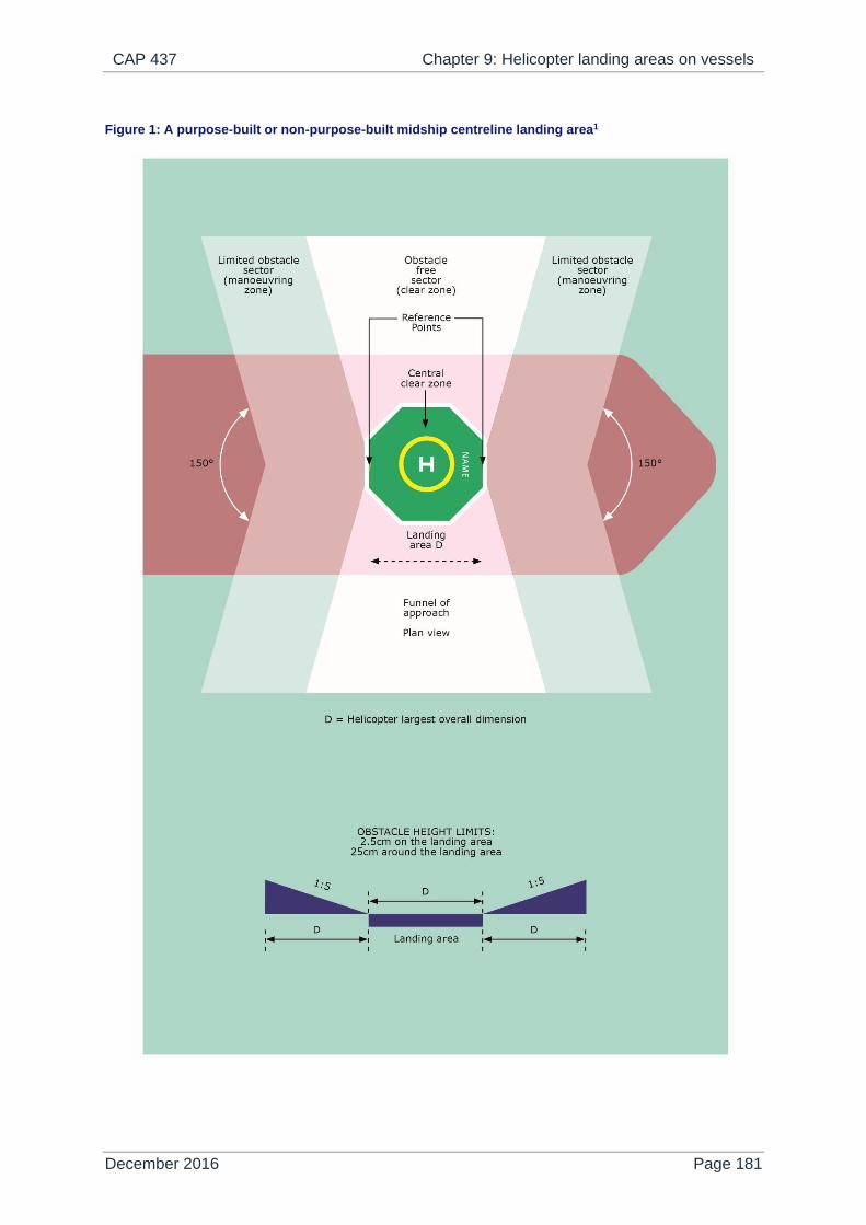
CAP 437 Chapter 9: Helicopter landing areas on vessels
December 2016 Page 181
Figure 1: A purpose-built or non-purpose-built midship centreline landing area1

CAP 437 Chapter 9: Helicopter landing areas on vessels
December 2016 Page 182
NOTE: Where the D-value is 16.00 m or less the obstacle height limitation around the
landing area is restricted to 5 cm (see paragraph 9.9).
Helicopter landing area marking and lighting
9.14 The basic marking and lighting requirements referred to at Chapter 4 and
Appendix C will also apply to helicopter landing areas on ships ensuring
that for amidships helicopter landing areas the TD/PM Circle should
always be positioned in the centre of the landing area and both the
forward and aft ‘origins’ denoting the LOS should be marked with a black
chevron (see Chapter 4, Figure 2). In addition, where there is an
operational requirement, vessel owners should consider providing the
helideck name marking and maximum allowable mass ‘t’ marking both
forward and aft of the painted helideck identification ‘H’ marking and
TD/PM Circle.
1 Figure courtesy of International Chamber of Shipping, Helicopter Ship Guide (2008).
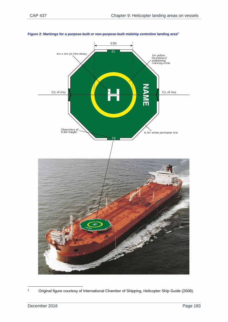
CAP 437 Chapter 9: Helicopter landing areas on vessels
December 2016 Page 183
Figure 2: Markings for a purpose-built or non-purpose-built midship centreline landing area2
2 Original figure courtesy of International Chamber of Shipping, Helicopter Ship Guide (2008).

CAP 437 Chapter 9: Helicopter landing areas on vessels
December 2016 Page 184
Ship’s side non-purpose-built landing area
9.15 A non-purpose-built landing area located on a ship’s side should consist
of a clear zone and a manoeuvring zone as shown in Figure 3. The clear
zone should be capable of containing a circle with a minimum diameter of
1 x D. No objects should be located within the clear zone except aids
whose presence is essential for the safe operation of the helicopter, and
then only up to a maximum height of 2.5 cm. Such objects should only be
present if they do not represent a hazard to helicopters. Where there are
immovable fixed objects located in the clear zone, such as a Butterworth
lid, these should be marked conspicuously and annotated on the ship’s
operating area diagram (a system of annotation is described in detail in
Appendix F to the ICS Helicopter Ship Guide). In addition, a manoeuvring
zone should be established, where possible, on the main deck of the ship.
The manoeuvring zone, intended to provide the helicopter with an
additional degree of protection to account for rotor overhang beyond the
clear zone, should extend beyond the clear zone by a minimum of 0.25D.
The manoeuvring zone should only contain obstacles whose presence is
essential for the safe operation of the helicopter, and up to a maximum
height of 25 cm. Where the D-circle accommodated is 16.00 m or less,
obstacles contained in the manoeuvring zone should not exceed a height
of 5 cm.

CAP 437 Chapter 9: Helicopter landing areas on vessels
December 2016 Page 185
Figure 3: Ship's side - Non-purpose-built landing area (16.0 m or greater)
9.16 Where the operating area is coincident with the ship’s side, and in order to
improve operational safety, the clear zone should extend to a distance of
1.5D at the ship’s side while the manoeuvring zone should extend to a
distance of 2D measured at the ship’s side. Within this area, the only
obstacles present should be those essential for the safe operation of the
helicopter, with a maximum height of 25 cm (or 5 cm where the D-circle
accommodated has a diameter of 16.00 m or less). Where there are
immovable fixed objects such as tank cleaning lines they should be
marked conspicuously and annotated on the ship’s operating area
diagram (see Appendix F in the ICS Helicopter Ship Guide).
9.17 Any railings located on the ship’s side should be removed or stowed
horizontally along the entire length of the manoeuvring zone at the ship’s
side (i.e. over a distance of at least 2D). All aerials, awnings, stanchions
and derricks and cranes within the vicinity of the manoeuvring zone
should be either lowered or securely stowed. All dominant obstacles
within, or adjacent to, the manoeuvring zone should be conspicuously
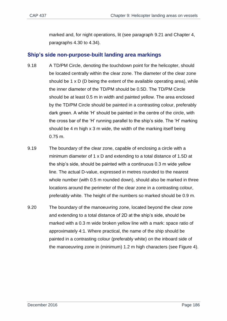
CAP 437 Chapter 9: Helicopter landing areas on vessels
December 2016 Page 186
marked and, for night operations, lit (see paragraph 9.21 and Chapter 4,
paragraphs 4.30 to 4.34).
Ship’s side non-purpose-built landing area markings
9.18 A TD/PM Circle, denoting the touchdown point for the helicopter, should
be located centrally within the clear zone. The diameter of the clear zone
should be 1 x D (D being the extent of the available operating area), while
the inner diameter of the TD/PM should be 0.5D. The TD/PM Circle
should be at least 0.5 m in width and painted yellow. The area enclosed
by the TD/PM Circle should be painted in a contrasting colour, preferably
dark green. A white ‘H’ should be painted in the centre of the circle, with
the cross bar of the ‘H’ running parallel to the ship’s side. The ‘H’ marking
should be 4 m high x 3 m wide, the width of the marking itself being
0.75 m.
9.19 The boundary of the clear zone, capable of enclosing a circle with a
minimum diameter of 1 x D and extending to a total distance of 1.5D at
the ship’s side, should be painted with a continuous 0.3 m wide yellow
line. The actual D-value, expressed in metres rounded to the nearest
whole number (with 0.5 m rounded down), should also be marked in three
locations around the perimeter of the clear zone in a contrasting colour,
preferably white. The height of the numbers so marked should be 0.9 m.
9.20 The boundary of the manoeuvring zone, located beyond the clear zone
and extending to a total distance of 2D at the ship’s side, should be
marked with a 0.3 m wide broken yellow line with a mark: space ratio of
approximately 4:1. Where practical, the name of the ship should be
painted in a contrasting colour (preferably white) on the inboard side of
the manoeuvring zone in (minimum) 1.2 m high characters (see Figure 4).

CAP 437 Chapter 9: Helicopter landing areas on vessels
December 2016 Page 187
Figure 4: Ship's side non-purpose-built landing area markings3

CAP 437 Chapter 9: Helicopter landing areas on vessels
December 2016 Page 188
Night operations
9.21 Details of landing area lighting for purpose-built landing areas are given at
Chapter 4 and Appendix C. In addition, Figure 5 shows an example of the
overall lighting scheme for night helicopter operations (example shows a
non-purpose-built ship’s side arrangement).
Figure 5: Representative landing area lighting scheme for a non-purpose-built ship’s side arrangement4
Poop deck operations
9.22 Poop deck operations are addressed fully in the ICS Guide.
3 Original figure courtesy of International Chamber of Shipping, Helicopter Ship Guide (2008). 4 Figure courtesy of International Chamber of Shipping, Helicopter Ship Guide (2008).

CAP 437 Chapter 10: Helicopter winching areas on vessels and on wind
turbine platforms
December 2016 Page 189
Chapter 10
Helicopter winching areas on vessels and on wind turbine platforms
Winching areas on vessels
10.1 Where practicable, the helicopter should always land rather than hoist,
because safety is enhanced when the time spent hovering is reduced. In
both cases the Vessel’s Master should be fully aware of, and in
agreement with, the helicopter pilot’s intentions.
10.2 The ICS has published a ‘Guide to Helicopter/Ship Operations’, updated
in 2008, which comprehensively describes physical criteria and
procedures applicable for a shipboard winching area operation. It is not
intended to reproduce the procedures from the ICS document in detail in
this eighth edition of CAP 437 and therefore the ICS Guide may need to
be referenced in addition to Chapter 10, paragraph 10.1.
Design and obstacle restriction
10.3 A winching area should be located over an area to which the helicopter
can safely hover whilst hoisting to or from the vessel. Its location should
allow the pilot an unimpeded view of the whole of the clear zone whilst
facilitating an unobstructed view of the vessel. The winching area should
be located so as to minimise aerodynamic and wave motion effects. The
area should preferably be clear of accommodation spaces (see also
paragraph 10.13) and provide adequate deck area adjacent to the
manoeuvring zone to allow for safe access to the winching area from
different directions. In selecting a winching area the desirability for
keeping the hoisting height to a minimum should also be borne in mind.
10.4 A winching area should provide a manoeuvring zone with a minimum
diameter of 2D (twice the overall dimension of the largest helicopter
permitted to use the area). Within the manoeuvring zone a clear zone

CAP 437 Chapter 10: Helicopter winching areas on vessels and on wind
turbine platforms
December 2016 Page 190
should be centred. This clear zone should be at least 5 m in diameter and
should be a solid surface capable of accommodating personnel and/or
stores during hoisting operations. It is accepted that a portion of the
manoeuvring zone, outside the clear area, may be located beyond the
ship’s side but should nonetheless comply with obstruction requirements
shown in Figure 1. In the inner portion of the manoeuvring zone no
obstructions should be higher than 3 m. In the outer portion of the
manoeuvring zone no obstructions should be higher than 6 m.
Visual aids
10.5 Winching area markings should be located so that their centres coincide
with the centre of the clear zone (see Figure 1).
10.6 The 5 m minimum diameter clear zone should be painted in a
conspicuous colour, preferably yellow, using non-slip paint.
10.7 A winching area outer manoeuvring zone marking should consist of a
broken circle with a minimum line width of 30 cm and a mark: space ratio
of approximately 4:1. The marking should be painted in a conspicuous
colour, preferably yellow. The extent of the inner manoeuvring zone may
be indicated by painting a thin white line, typically 10 cm thickness.
10.8 Within the manoeuvring zone, in a location adjacent to the clear area,
‘WINCH ONLY’ should be easily visible to the pilot, painted in not less
than 2 m characters, in a conspicuous colour.
10.9 Where hoisting operations to vessels are required at night, winching area
floodlighting should be provided to illuminate the clear zone and
manoeuvring zone areas. Floodlights should be arranged and adequately
shielded so as to avoid glare to pilots operating in the hover.
10.10 The spectral distribution of winching area floodlights should be such that
the surface and obstacle markings can be clearly identified. The
floodlighting arrangement should ensure that shadows are kept to a
minimum.
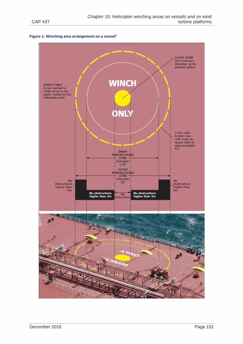
CAP 437 Chapter 10: Helicopter winching areas on vessels and on wind
turbine platforms
December 2016 Page 191
Figure 1: Winching area arrangement on a vessel5

CAP 437 Chapter 10: Helicopter winching areas on vessels and on wind
turbine platforms
December 2016 Page 192
Obstructions
10.11 To reduce the risk of a hoist hook or cable becoming fouled, all guard
rails, awnings, stanchions, antennae and other obstructions within the
vicinity of the manoeuvring zone should, as far as possible, be either
removed, lowered or securely stowed.
10.12 All dominant obstacles within, or adjacent to, the manoeuvring zone
should be conspicuously marked and, for night operations, be adequately
illuminated (see paragraphs 10.9 and 10.10. Also see Chapter 4,
paragraphs 4.30 to 4.34).
Hoisting above accommodation spaces
10.13 Some vessels may only be able to provide winching areas which are
situated above accommodation spaces. Due to the constraints of
operating above such an area only twin-engined helicopters should be
used for such operations and the following procedures adhered to:
Personnel should be cleared from all spaces immediately below the
helicopter operating area and from those spaces where the only
means of escape is through the area immediately below the
operating area.
Safe means of access to and escape from the operating area should
be provided by at least two independent routes.
All doors, ports, skylights etc. in the vicinity of the aircraft operating
area should be closed. This also applies to deck levels below the
operating area.
Fire and rescue personnel should be deployed in a ready state but
sheltered from the helicopter operating area.
Helicopter winching areas on wind turbine platforms
NOTE 1: CAP 764 provides CAA policy and guidelines on wind turbines.
5 Figure courtesy of International Chamber of Shipping, Helicopter Ship Guide (2008).

CAP 437 Chapter 10: Helicopter winching areas on vessels and on wind
turbine platforms
December 2016 Page 193
NOTE 2: Helicopter hoist operations to wind turbine platforms should be conducted by day
in Visual Meteorological Conditions (VMC) only.
NOTE 3: The platform design criteria in the following paragraphs have been developed to
promote a 'safe and friendly' environment for helicopter hoist operations. It
should be recognised that any departure from 'best practice' topside
arrangements / platform designs laid out in paragraphs 10.14 to 10.26, including
deviations from specified dimensions, has potential to compromise the 'safe and
friendly' environment secured for helicopter hoist operations. Therefore any
proposed conceptual arrangements should be subjected to appropriate testing
including wind tunnel testing and/or CFD studies to establish the wind
environment at and above the operating area. Studies undertaken should assess
any impact on safe operations that may be caused by an increase in the
incidence of turbulence and/or of rotor downwash effects as a result of proposed
modified topside arrangements / platform design.
Platform design
10.14 The winching area platform (clear area) should be square or rectangular
and capable of containing a circle having a minimum diameter of 4.0 m.
10.15 In addition to the winching area platform, provision needs to be made for a
safety zone to accommodate Helicopter Hoist Operations Passengers
(HHOP) at a safe distance away from the winching area during helicopter
hoist operations. The minimum safe distance is deemed to be not less
than 1.5 m from the inboard edge of the winching (clear) area.
10.16 The safety zone should be connected by an access route to the winching
area platform located inboard of the winching area platform. The safety
zone and associated access route should have the same surface
characteristics as the winching area platform (see paragraphs 10.18,
10.19 and 10.20) except that the overall size may be reduced, such that
the dimensions of the safety zone and access route are not less than 2.5
m (length) x 0.9 m (width).
CAP 437 Chapter 10: Helicopter winching areas on vessels and on wind
turbine platforms
December 2016 Page 194
NOTE: The dimensions of the safety zone may need to be increased according to the
maximum number of HHOP that need to be accommodated safely away from the
winching (clear) area during helicopter hoist operations.
10.17 To differentiate the safety zone and the associated access route from the
winching area, it is recommended that the safety zone and access route
be painted in contrasting colours to indicate to HHOP where it is safe to
congregate during helicopter hoist operations (see paragraph 10.27 and
Figure 2).
10.18 The platform should be constructed so that it generates as little turbulence
as possible. The overall platform design should take account of the need
for downdraft from the main rotor to disperse away from the platform. The
incidence regarding the discharge of static electricity from the helicopter
should be addressed by ensuring that the platform is capable of grounding
the hoist wire and aircraft.
10.19 The platform deck should be capable of supporting a mass that is
approximately five times the weight of an average HHOP.
10.20 The surface of the platform, including the safety zone and associated
access route, should display suitable friction characteristics to ensure the
safe movement of HHOP in all conditions. The minimum friction
coefficient, which should be verified prior to installation, is 0.5.
10.21 The winching area platform and associated access route and safety zone
should be completely enclosed by a 1.5 m high railing system to ensure
the safety and security of HHOP at all times. The design of the safety rails
should ensure that a free flow of air through the structure is not prevented
or disrupted whilst also guaranteeing that no possibility exists for the hoist
hook to get entangled in the railing or in any other part of the platform
structure. It is permitted for the 1.5m high railing system to be located
along the edge, within the specified clear area, of the winching area
platform, the associated access route and safety zone.

CAP 437 Chapter 10: Helicopter winching areas on vessels and on wind
turbine platforms
December 2016 Page 195
10.22 The surface of the platform should be essentially flat for helicopter hoist
operations. However, the floor may slope down towards the outboard
edge of the platform to prevent the pooling of water on the platform. It is
recommended that a slope not exceeding 2% (1:50) be provided.
10.23 The outboard edge of the winching area platform should be located at a
minimum horizontal distance from the plane of rotation of the turbine
blades that is not less than 1 x the Rotor Diameter (RD) of the largest
helicopter intending to conduct hoist operations to the platform. For single
main rotor types, the RD is assumed to represent the largest overall width
dimension of the helicopter, so that for the widest helicopter authorised to
operate to the platform, when located with the centre of the disc directly
above the outboard edge of the platform (as depicted in Figure 3), a
minimum rotor-tip-to-obstacle clearance of ½ RD (i.e. one rotor radius) is
assured. To make allowance for circumstances that may require a
helicopter in the hover to move laterally from the edge of the platform in
the direction of the turbine blades, a reduction in the minimum rotor-tip-to-
obstacle clearance below ½ RD may be permitted. However, in no
circumstances should the clearance between the tip-path plane of the
main rotor and the plane of rotation of the turbine blades be reduced
below 4 m for any helicopter intending to conduct hoist operations to the
platform.
10.24 During helicopter hoist operations, it is essential that the nacelle should
not turn in azimuth and that the turbine blades should also be prevented
from rotating by the application of the braking system. Experience in other
sectors indicates that it is normal practice for the nacelle to be motored 90
degrees out of wind so that the upwind blade is horizontal and points into
the prevailing wind. This is considered to be the preferred orientation for
helicopter hoist operations; however, the actual orientation of the blades
may vary to suit specific operational requirements.

CAP 437 Chapter 10: Helicopter winching areas on vessels and on wind
turbine platforms
December 2016 Page 196
Obstacle restriction
10.25 Within a horizontal distance of 1.5 m measured from the winching (clear)
area, no obstacles are permitted to extend above the top of the 1.5 m
railing.
10.26 Beyond 1.5 m, and out to a distance corresponding to the plane of rotation
of the turbine rotor blades, obstacles are permitted up to a height not
exceeding 3 m above the surface of the winching area. It is required that
only fixed obstacles essential to the safety of the operation are present,
e.g. anemometer masts, communications antennae, helihoist status light
etc.
Visual aids
10.27 The surface of the winching area (a minimum 4 m square 'clear area')
should be painted yellow. For the safety zone, green is recommended and
a contrasting grey for the associated access route (see Figure 2).
10.28 The railings around the entire winching area, safety zone and associated
access route should be painted in a conspicuous colour, preferably red.
10.29 The wind turbine structure should be clearly identifiable from the air using
a simple designator (typically a two-digit or three-digit number with block
identification), painted in 1.5 m (minimum) characters in a contrasting
colour, preferably black. The turbine designator should be painted on the
nacelle top cover ideally utilising an area adjacent to the turbine rotor
blades.
10.30 A procedure should be put in place to indicate to the helicopter operator
that the turbine blades and nacelle are safely secured in position prior to
helicopter hoist operations commencing. Experience in other sectors has
demonstrated that this is best achieved by the provision of a helihoist
status light located on the nacelle of the WTG within the pilot's field of
view, which is capable of being operated remotely and from the platform
itself or from within the nacelle. In consultation with the industry CAA has
developed a system specification utilising a green light capable of

CAP 437 Chapter 10: Helicopter winching areas on vessels and on wind
turbine platforms
December 2016 Page 197
displaying in both steady and flashing signal mode. A steady green light is
displayed to indicate to the pilot that the turbine blades and nacelle are
secure and it is safe to operate. A flashing green light is displayed to
indicate that the turbine is in a state of preparation to accept hoist
operations or, when displayed during hoist operations, that parameters
are moving out of limits. When the light is extinguished this indicates to
the operator that it is not safe to conduct helicopter hoist operations. The
full specification for a heli-hoist status light is reproduced at Appendix J.
10.31 Requirements for lighting of wind turbine generators in United Kingdom
territorial waters, aimed at 'warning off' aircraft transiting the generic area,
are addressed in Article 223 of the ANO 2016. See also Directorate of
Airspace Policy – Policy Statement for The Lighting of Wind Turbine
Generators in United Kingdom Territorial Waters.
10.32 Obstruction lighting in the vicinity of the winching area that has a potential
to cause glare or dazzle to the pilot or to a helicopter hoist operations
crew member should be switched off prior to, and during, helicopter hoist
operations.
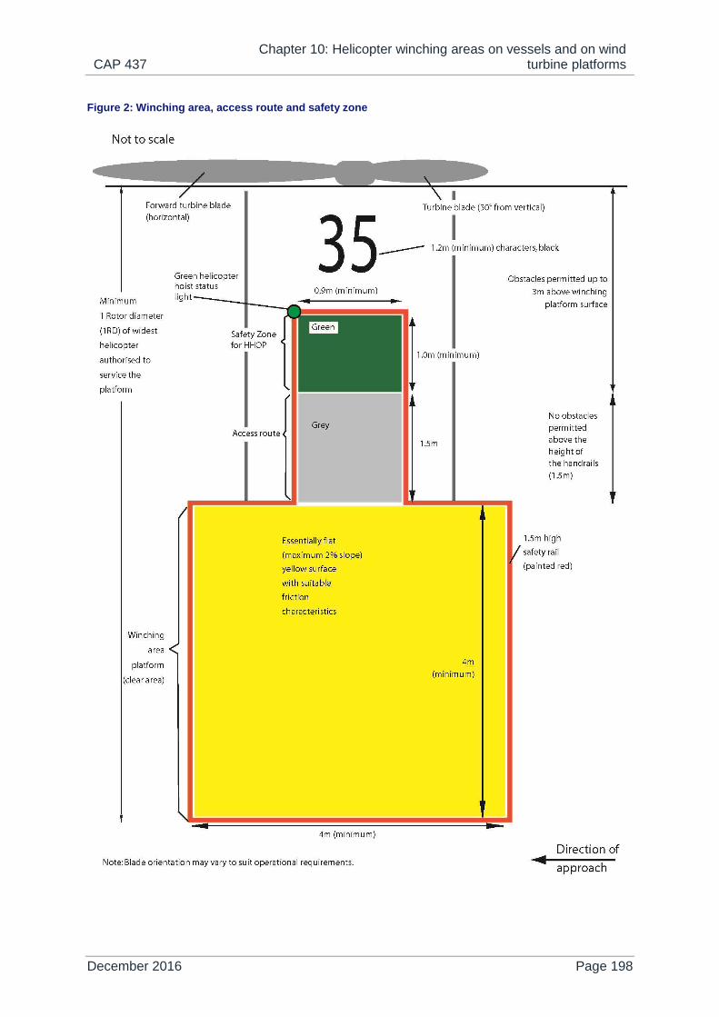
CAP 437 Chapter 10: Helicopter winching areas on vessels and on wind
turbine platforms
December 2016 Page 198
Figure 2: Winching area, access route and safety zone

CAP 437 Chapter 10: Helicopter winching areas on vessels and on wind
turbine platforms
December 2016 Page 199
Figure 3: General arrangement drawing showing surfaces and sectors

CAP 437 Chapter 10: Helicopter winching areas on vessels and on wind
turbine platforms
December 2016 Page 200
Further operational conditions
10.33 For UK operations it is understood to be normal practice for the hoist
arrangement to be located on the right hand side of the helicopter with the
pilot positioned just on the inboard side of the outboard winching (clear
area) platform railings (see Figure 3). In this configuration the pilot’s
perspective of the platform and turbine blade arrangement should be
unimpeded and it is not considered usually necessary to provide any
additional visual cues to assist in the maintenance of a safe lateral
distance between the helicopter main rotor and the nearest dominant
obstacle.
10.34 Where cross-cockpit helicopter hoist operations are envisaged an aiming
point system may need to be established to assist the pilot in determining
the position of the helicopter in relation to the winching area platform and
to obstacles. This may be achieved by the provision of a sight point
marker system or similar aids. Further guidance may be obtained from
Flight Operations Inspectorate (Helicopters) Section.
10.35 Offshore Renewables Aviation Guidance (ORAG) on Good Practices for
Offshore Renewable Energy Developments was published by
RenewableUK in June 2016 - see Appendix B. It is recommended that
helicopter hoist operators consult this additional reference source.

CAP 437 Use of offshore locations
December 2016 Page 201
Appendix A
Use of offshore locations
AMC1 SPA.HOFO.115
General
A.1 The operations manual relating to the specific usage of offshore helicopter
landing areas (Part C for CAT operators) should contain, or make
reference to, a directory of helidecks (Helideck Directory (HD)) intended to
be used by the operator. The directory should provide details of helideck
limitations and a pictorial representation of each offshore location and its
helicopter landing area recording all necessary information of a
permanent nature using a standardised template. The HD entries should
show, and be amended as necessary, the most recent status of each
helideck concerning non-compliance with applicable national standards
(i.e. UK CAA CAP 437), limitations, warnings, cautions or other comments
of operational importance. An example of a typical template is shown in
figure 1 of GM1 SPA.HOFO.115.
A.2 In order to ensure that the safety of flights is not compromised, the
operator should obtain relevant information and details for compilation of
the HD, and the pictorial representation from the owner/operator of the
offshore helicopter landing area.
A.3 If more than one name of the offshore location exists, the common name
painted on the surface of the landing area should be listed, but other
names should also be included in the HD (e.g. radio call sign if different).
After renaming an offshore location, the old name should also be included
in the HD for the following 6 months.
A.4 Any limitations associated with an offshore location should be included in
the HD. With complex installation arrangements including combinations of
installations/vessels (e.g. Combined Operations), a separate listing in the

CAP 437 Use of offshore locations
December 2016 Page 202
HD, accompanied by diagrams/pictures where necessary, may be
required.
A.5 Each offshore helicopter landing area should be inspected and assessed
based on limitations, warnings, instructions and restrictions to determine
its acceptability with respect to the following as a minimum:
1) The physical characteristics of the landing area including size and
load bearing capability and the appropriate ‘D’ and ‘t’ values.
NOTE: ‘D’ is the overall length of the helicopter from the most forward position of main
rotor tip to the most rearward position of tail rotor tip plane path, or rearmost
extension of the fuselage in the case of fenestron or Notar tails. ‘t’ is the
maximum allowable mass in tonnes.
2) The preservation of obstacle-protected surfaces (an essential
safeguard for all flights). These surfaces are:
a) the minimum 210° obstacle-free surface (OFS) above helideck
level;
b) the 150° limited obstacle surface (LOS) above helideck level;
and
c) the minimum 180° falling ‘5:1’ gradient with respect to
significant obstacles below helideck level.
If these sectors/surfaces are infringed, even on a temporary basis,
and/or if an adjacent installation or vessel infringes the obstacle
protected surfaces related to the landing area, an assessment
should be made to determine whether it is necessary to impose
operating limitations and/or restrictions to mitigate any non-
compliance with the criteria.
3) Marking and lighting:
a) for operations at night, adequate illumination of the perimeter of
the landing area, utilising perimeter lighting meeting national
requirements (i.e UK CAA CAP 437);
b) for operations at night, adequate illumination of the location of
the touchdown marking by use of a lit touchdown/positioning

CAP 437 Use of offshore locations
December 2016 Page 203
marking and lit heliport identification marking meeting national
requirements (i.e.UK CAA CAP 437);
c) status lights (for night and day operations, indicating the status
of the helicopter landing area e.g. a red flashing light indicates
‘landing area unsafe: do not land’) meeting national
requirements (i.e. UK CAA CAP 437);
d) dominant obstacle paint schemes and lighting;
e) condition of helideck markings; and
f) adequacy of general installation and structure lighting.
Any limitations with respect to non-compliant lighting arrangements
may require the HD to be annotated ‘daylight only operations’.
4) Deck surface:
a) assessment of surface friction;
b) adequacy and condition of helideck net (where provided);
c) fit for purpose drainage system;
d) deck edge safety netting or shelving;
e) a system of tie-down points adequate for the range of
helicopters in use; and
f) procedures to ensure that the surface is kept clean of all
contaminants e.g. bird guano, sea spray, snow and ice.
5) Environment:
a) foreign object damage;
b) an assessment of physical turbulence generators e.g.
structure-induced turbulence due to clad derrick;
c) bird control measures;
d) air flow degradation due to gas turbine exhaust emissions
(turbulence and thermal effects), flares (thermal effects) or cold
gas vents (unburned flammable gas); and
e) adjacent offshore installations may need to be included in the
environmental assessment.
To assess for potential adverse environmental effects described in
(b), (d) and (e), an offshore location should be subject to appropriate
studies e.g. wind tunnel testing, CFD analysis.
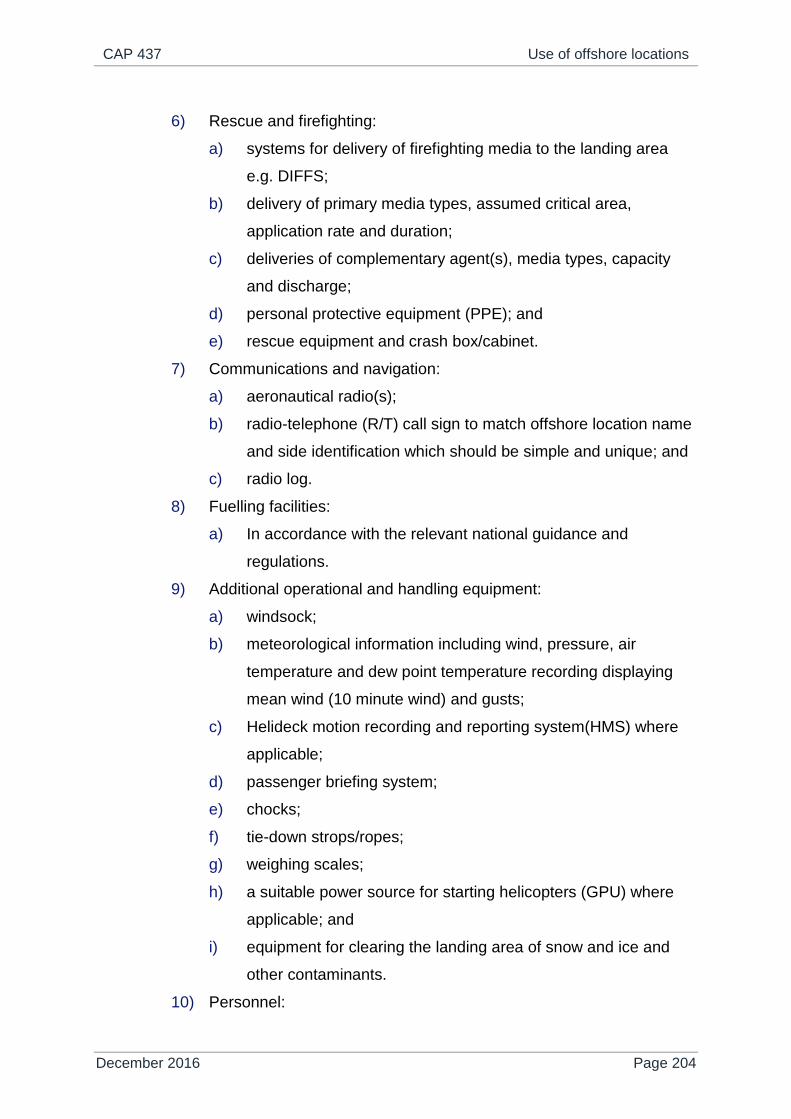
CAP 437 Use of offshore locations
December 2016 Page 204
6) Rescue and firefighting:
a) systems for delivery of firefighting media to the landing area
e.g. DIFFS;
b) delivery of primary media types, assumed critical area,
application rate and duration;
c) deliveries of complementary agent(s), media types, capacity
and discharge;
d) personal protective equipment (PPE); and
e) rescue equipment and crash box/cabinet.
7) Communications and navigation:
a) aeronautical radio(s);
b) radio-telephone (R/T) call sign to match offshore location name
and side identification which should be simple and unique; and
c) radio log.
8) Fuelling facilities:
a) In accordance with the relevant national guidance and
regulations.
9) Additional operational and handling equipment:
a) windsock;
b) meteorological information including wind, pressure, air
temperature and dew point temperature recording displaying
mean wind (10 minute wind) and gusts;
c) Helideck motion recording and reporting system(HMS) where
applicable;
d) passenger briefing system;
e) chocks;
f) tie-down strops/ropes;
g) weighing scales;
h) a suitable power source for starting helicopters (GPU) where
applicable; and
i) equipment for clearing the landing area of snow and ice and
other contaminants.
10) Personnel:
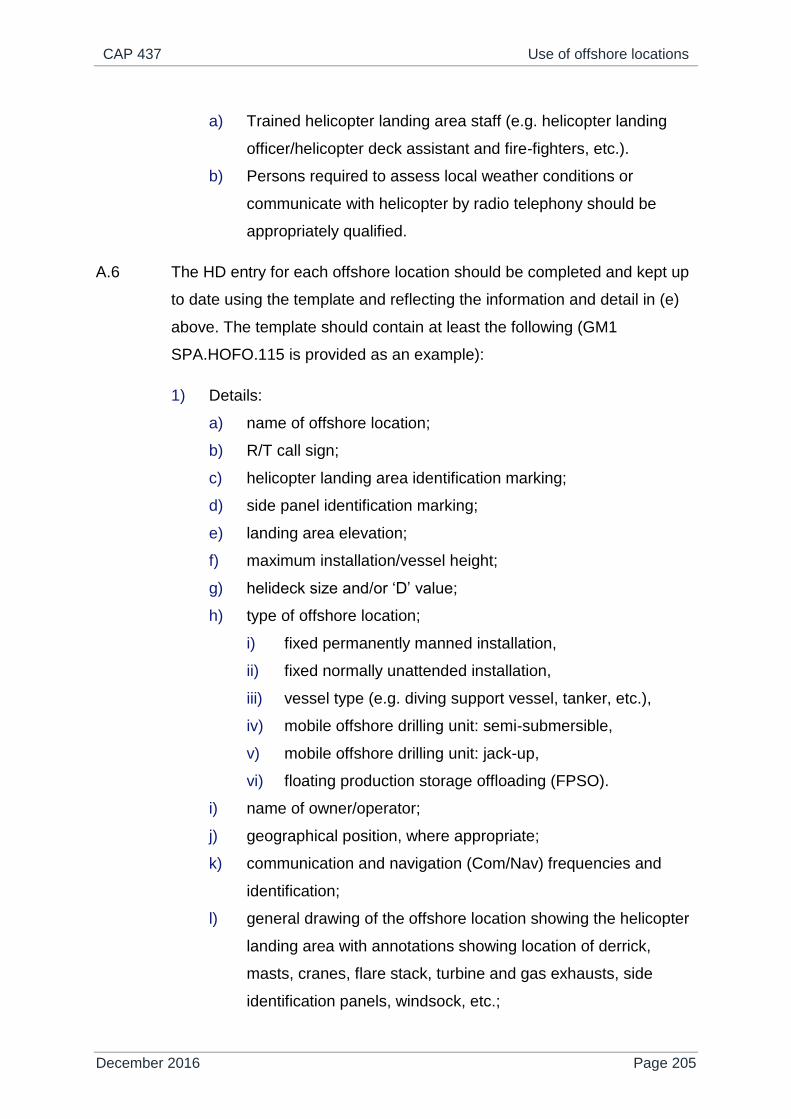
CAP 437 Use of offshore locations
December 2016 Page 205
a) Trained helicopter landing area staff (e.g. helicopter landing
officer/helicopter deck assistant and fire-fighters, etc.).
b) Persons required to assess local weather conditions or
communicate with helicopter by radio telephony should be
appropriately qualified.
A.6 The HD entry for each offshore location should be completed and kept up
to date using the template and reflecting the information and detail in (e)
above. The template should contain at least the following (GM1
SPA.HOFO.115 is provided as an example):
1) Details:
a) name of offshore location;
b) R/T call sign;
c) helicopter landing area identification marking;
d) side panel identification marking;
e) landing area elevation;
f) maximum installation/vessel height;
g) helideck size and/or ‘D’ value;
h) type of offshore location;
i) fixed permanently manned installation,
ii) fixed normally unattended installation,
iii) vessel type (e.g. diving support vessel, tanker, etc.),
iv) mobile offshore drilling unit: semi-submersible,
v) mobile offshore drilling unit: jack-up,
vi) floating production storage offloading (FPSO).
i) name of owner/operator;
j) geographical position, where appropriate;
k) communication and navigation (Com/Nav) frequencies and
identification;
l) general drawing of the offshore location showing the helicopter
landing area with annotations showing location of derrick,
masts, cranes, flare stack, turbine and gas exhausts, side
identification panels, windsock, etc.;
CAP 437 Use of offshore locations
December 2016 Page 206
m) plan view drawing, chart orientation from the general drawing,
to show the above. The plan view will also show the 210
degree sector orientation in degrees true;
n) type of fuelling:
i) pressure and gravity,
ii) pressure only,
iii) gravity only,
iv) none.
o) type and nature of fire-fighting equipment;
p) availability of ground power unit (GPU);
q) deck heading;
r) ‘t’ value and any approved variations;
s) status light system (yes/no);
t) revision date of publication; and
u) one or more diagram/photograph and any other suitable
guidance to assist pilots.
A.7 For offshore locations on which there is incomplete information, ‘restricted’
usage based on the information available may be considered by the
operator, subject to risk assessment prior to the first helicopter visit.
During subsequent operations, and before any restriction on usage is
lifted, information should be gathered and the following should apply:
1) Pictorial (static) representation:
a) template blanks (GM1 SPA.HOFO.115 is provided as an
example) should be available to be filled in during flight
preparation on the basis of the information given by the
offshore location owner/operator and flight crew observations;
b) where possible, suitably annotated photographs may be used
until the HD entry and template have been completed;
c) until the HD entry and template have been completed,
conservative operational restrictions (e.g. performance, routing,
etc.) may be applied;
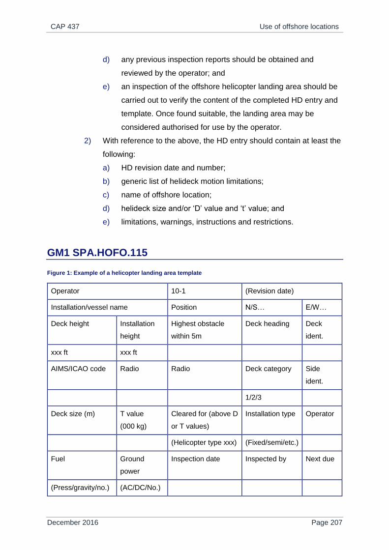
CAP 437 Use of offshore locations
December 2016 Page 207
d) any previous inspection reports should be obtained and
reviewed by the operator; and
e) an inspection of the offshore helicopter landing area should be
carried out to verify the content of the completed HD entry and
template. Once found suitable, the landing area may be
considered authorised for use by the operator.
2) With reference to the above, the HD entry should contain at least the
following:
a) HD revision date and number;
b) generic list of helideck motion limitations;
c) name of offshore location;
d) helideck size and/or ‘D’ value and ‘t’ value; and
e) limitations, warnings, instructions and restrictions.
GM1 SPA.HOFO.115
Figure 1: Example of a helicopter landing area template
Operator 10-1 (Revision date)
Installation/vessel name Position N/S… E/W…
Deck height Installation
height
Highest obstacle
within 5m
Deck heading Deck
ident.
xxx ft xxx ft
AIMS/ICAO code Radio Radio Deck category Side
ident.
1/2/3
Deck size (m) T value
(000 kg)
Cleared for (above D
or T values)
Installation type Operator
(Helicopter type xxx) (Fixed/semi/etc.)
Fuel Ground
power
Inspection date Inspected by Next due
(Press/gravity/no.) (AC/DC/No.)

CAP 437 Use of offshore locations
December 2016 Page 208
Wind direction Wind speed Limitations
(All)
(000-050)
All
(>30)
(Performance requirements)
(Table 2)
etc.
5:1 non-compliances
Additional information

CAP 437 Bibliography
December 2016 Page 209
Appendix B
Bibliography
References
Where a chapter is indicated below it shows where in this CAP the document is
primarily referenced.
Health and Safety Executive
Chapter 1
A guide to the Integrity, Workplace Environment and Miscellaneous Aspects of the
Offshore Installations and Wells (Design and Construction, etc.) Regulations 1996
HSE Books ISBN 0 7176 1164 7
A guide to the Offshore Installations (Safety Case) Regulations 2005, Third edition
2006 HSE Books, ISBN 0 7176 6184 9
A guide to the Offshore Installations and Pipeline Works (Management and
Administration) Regulations 1995 HSE Books ISBN 0 7176 0938 3
Prevention of Fire and Explosion, and Emergency Response on Offshore
Installations, Approved Code of Practice and Guidance 1995, HSE Books ISBN 0
7176 0874 3
Chapter 2
Offshore Information Sheet No. 6/2011: Offshore helidecks – testing of helideck
foam production systems, August 2011
Chapter 3
Offshore Information Sheet No. 5/2011: Offshore helideck design considerations –
environment effects, June 2011

CAP 437 Bibliography
December 2016 Page 210
Chapter 4
Operations Notice No. 39: Guidance on identification of offshore installations, June
2008
International Civil Aviation Organization
ICAO Annex 3 Meteorological Service for International Air Navigation
ICAO Annex 14 Volume II Heliports
ICAO Doc 9261 AN/903 Heliport Manual
ICAO Doc 9284 AN/905 Technical Instruction for the Safe Transport of
Dangerous Goods by Air
Other publications
Chapter 3
IMO (International Maritime Organization) Mobile Offshore Drilling Units (MODU)
Code (2001 consolidated)
ISO (International Organization for Standardization) International Standard ISO
19901-3: Petroleum and Natural Gas Industries – Specific Requirements for
Offshore Structures, Part 3: topsides structure (2010-12-10) www.iso.org
Oil & Gas UK Guidelines for the Management of Aviation Operations (Issue 6 - April
2011)
Review of falling 5-in-1 Gradient Criteria of Offshore Platform Operations.
Dr Douglas G Thomson/Prof Roy Bradley – Final Report March 1997. Dr Douglas G
Thomson – Addendum to Final Report – July 1999
Chapter 5
Offshore Petroleum Industry Training Organisation (OPITO) Helicopter Landing
Officer’s Handbook (10th Edition, 2014)
Chapter 6
UKOOA Guidelines for Safety Related Telecommunications Systems On Fixed
Offshore Installations
CAP 437 Bibliography
December 2016 Page 211
WMO (World Meteorological Organization) Publication No. 306 Manual on Codes
Volume 1.1, Part A Alphanumeric Codes, Code Table 3700 State of the Sea
Chapter 8
Helicopter Refuelling Handbook (7th Edition, 2014)
Chapter 9
Guide to Helicopter/Ship Operations, International Chamber of Shipping, Fourth
Edition, December 2008
Civil Aviation Authority – CAPs, research papers and policy
statements
Foreword
CAP 1145 Safety review of offshore public transport helicopter
operations in support of the exploitation of oil and gas
CAP 1243 Safety review of offshore public transport helicopter
operations in support of the exploitation of oil and Gas.
Progress report
CAP 1295 Consultation: The CAA's intention to assume responsibility
for the certification of UK helidecks
CAP 1386 Safety review of offshore public transport helicopter
operations in support of the exploitation of oil and gas.
Progress report: 2016
Chapter 1
CAP 1484 CAA/HSE/HSENI Memorandum of Understanding guidance
(January 2017)
Chapter 3
CAA Paper 99004 Research on Offshore Helideck Environmental Issues
CAA Paper 2007/02 Visualisation of Offshore Gas Turbine Exhaust Plumes

CAP 437 Bibliography
December 2016 Page 212
CAA Paper 2008/02
Study I
Validation of the Helicopter Turbulence Criterion for
Operations to Offshore Platforms
CAA Paper 2008/02
Study II
A review of 0.9 m/s Vertical Wind Component Criterion for
Helicopters Operating to Offshore Installations
CAA Paper 2008/03 Helideck Design Considerations: Environmental Effects
Chapter 4
CAA Paper 2004/01 Enhancing Offshore Helideck Lighting – NAM K14 Trials
CAA Paper 2005/01 Enhancing Offshore Helideck Lighting – Onshore Trials at
Longside airfield
CAA Paper 2006/03 Enhancing Offshore Helideck Lighting – Onshore Trials at
Norwich Airport
CAA Paper 2008/01 Specification for an Offshore Helideck Status Light System
CAA Paper 2012/03 Specification for an Offshore Helideck Lighting System
Chapter 6
CAP 413 Radiotelephony Manual
CAP 452 Aeronautical Radio Station Operator’s Guide
CAP 670 Air Traffic Services Safety Requirements
CAP 746
(Appendix H)
Meteorological Observations at Aerodromes (Competency
of Observers)
Chapter 7
CAP 748 Aircraft Fuelling and Fuel Installation Management
Chapter 10
CAP 764 CAA Policy and Guidelines on Wind Turbines
CAP 789 Requirements and Guidance Material for Operators
DAP Policy
Statement
The Lighting of Wind Turbine Generators in United Kingdom
Territorial Waters

CAP 437 Bibliography
December 2016 Page 213
ORAG Offshore Renewables Aviation Guidance (ORAG) Good
Practice Guidelines for Offshore Renewable Energy
Developments June 2016
Sources
British Standards (BS) may be obtained from Her Majesty’s Stationery Office, PO
Box 276, Nine Elms Lane, London SW8 5DT. Telephone +44 (0) 20 7211 5656 or
from any HMSO. Advice on relevant codes (BS, EN and PREN) is available from the
CAA at SRG Gatwick.
Civil Aviation Publications (CAPs) and Civil Aviation Authority Papers (CAA Papers)
are published on the CAA website at www.caa.co.uk where you may register for e-
mail notification of amendments. Please see the inside cover of this CAP for details
of availability of paper copy.
HSE Publications from HSE Books, PO Box 1999, Sudbury, Suffolk, CO10 2WA.
Telephone +44 (0) 1787 881165 or e-mail [email protected]. Most
documents can be downloaded from HSE’s website www.hse.gov.uk.
ICAO Publications are available from Airplan Flight Equipment, 1a Ringway Trading
Estate, Shadowmoss Road, Manchester M22 5LH. Telephone +44 (0) 161 499 0023.
The ICAO website address is www.icao.int.
International Chamber of Shipping Publications from International Chamber of
Shipping, 12 Carthusian Street, London, EC1M 6EZ. Telephone +44 (0) 20 7417
2855. E-mail [email protected].
Oil & Gas UK Publications from Oil & Gas UK, 2nd Floor, 232-242 Vauxhall Bridge
Road, London SW1V 1AU. Telephone +44 (0) 20 7802 2400. Website
oilandgasuk.co.uk. E-mail [email protected].
OPITO Publications from OPITO, Inchbraoch house, South Quay, Ferryden,
Montrose, Scotland, DD10 9SL. Telephone +44 (0) 1674 662500.

CAP 437 Bibliography
December 2016 Page 214
RenewableUK, Greencoat House, Francis Street, London SW1P1DH. Telephone
+44 (0) 20 7901 3000. Website: www.RenewableUK.com. E-mail

CAP 437 Specification for helideck lighting scheme comprising perimeter lights, lit
touchdown/positioning marking and lit heliport identification marking
December 2016 Page 215
Appendix C
Specification for helideck lighting scheme comprising perimeter lights, lit touchdown/positioning marking and lit heliport identification marking
Overall operational requirement
C.1 The whole lighting configuration should be designed to be visible over a
range of 3600 in azimuth. It is possible, however, that on some offshore
installations the lighting may be obscured from the pilots’ view by topsides
structure when viewed from some directions. The design of the helideck
lighting is not required to address any such obscuration.
C.2 The visibility of the lighting configuration should be compatible with the
normal range of helicopter vertical approach paths from a range of 2
nautical miles (NM).
C.3 The purpose of the lighting configuration is to aid the helicopter pilot
perform the necessary visual tasks during approach and landing as stated
in Table 1.
Table 1: Visual tasks during approach and landing
Phase of
approach Visual task Visual cues/aids
Desired range
(NM)
5,000m
met. vis.
1,400 m
met. vis.
Helideck
location and
identification
Search within
platform structure
Shape of helideck; colour of
helideck; luminance of
helideck, perimeter lighting.
1.5
(2.8 km)
0.75
(1.4 km)
Final
approach
Detect helicopter
position in three
Apparent size/shape and
change of size/shape of
1.0
(1.8 km)
0.5
(900 m)

CAP 437 Specification for helideck lighting scheme comprising perimeter lights, lit
touchdown/positioning marking and lit heliport identification marking
December 2016 Page 216
axes, detect rate
of change of
position.
helideck, orientation and
change of orientation of
known features/markings/lights.
Hover and
landing
Detect helicopter
attitude, position
and rate of change
of position in three
axes (six degrees
of freedom).
Known
features/markings/lights,
Helideck texture.
0.03
(50 m)
0.03
(50 m)
C.4 The minimum intensities of the lighting configuration should be adequate
to ensure that, for a minimum Meteorological Visibility (Met. Vis.) of 1400
m and an illuminance threshold of 10-6.1 lux, each feature of the system
is visible and useable at night from ranges in accordance with C.5, C.6
and C.7.
C.5 The Perimeter Lights are to be visible at night from a minimum range of
0.75 NM.
C.6 The Touchdown/Positioning Marking (TD/PM) Circle on the helideck is to
be visible at night from a range of 0.5 NM.
C.7 The Heliport Identification Marking (‘H’) is to be visible at night from a
range of 0.25 NM.
C.8 The minimum ranges at which the TD/PM Circle and ‘H’ are visible and
useable (see paragraphs C.6 and C.7 above), should still be achieved
even where a correctly fitted landing net covers the lighting.
C.9 The design of the Perimeter Lights, TD/PM Circle and ‘H’ should be such
that the luminance of the Perimeter Lights is equal to or greater than that
of the TD/PM circle segments, and the luminance of the TD/PM circle
segments equal to or greater than that of the ‘H’.
C.10 The design of the TD/PM Circle and ‘H’ should include a facility to enable
their intensity to be increased by up to approximately two times the figures

CAP 437 Specification for helideck lighting scheme comprising perimeter lights, lit
touchdown/positioning marking and lit heliport identification marking
December 2016 Page 217
given in this specification to permit a once-off (tamper proof) adjustment at
installation; the maximum figures should not be exceeded. The purpose of
this facility is to ensure adequate performance at installations with high
levels of background lighting without risking glare at less well-lit
installations. The TD/PM Circle and ‘H’ should be adjusted together using
a single control to ensure that the balance of the overall lighting system is
maintained in both the ‘standard’ and ‘bright’ settings.
Definitions
C.11 The following definitions should apply:
Lighting element
C.12 A lighting element is a light source within a segment or sub-section and
may be discrete (e.g. a Light Emitting Diode (LED)) or continuous (e.g.
fibre optic cable, electro luminescent panel). An individual lighting element
may consist of a single light source or multiple light sources arranged in a
group or cluster, and may include a lens/diffuser.
Segment
C.13 A segment is a section of the TD/PM circle lighting. For the purposes of
this specification, the dimensions of a segment are the length and width of
the smallest possible rectangular area that is defined by the outer edges
of the lighting elements, including any lenses/diffusers.
Sub-section
C.14 A sub-section is an individual section of the ‘H’ lighting. For the purposes
of this specification, the dimensions of a sub-section are the length and
width of the smallest possible rectangular area that is defined by the outer
edges of the lighting elements, including any lenses/diffusers.

CAP 437 Specification for helideck lighting scheme comprising perimeter lights, lit
touchdown/positioning marking and lit heliport identification marking
December 2016 Page 218
The perimeter light requirement
Configuration
C.15 Perimeter lights, spaced at intervals of not more than 3 m, should be fitted
around the perimeter of the landing area of the helideck as described in
Chapter 4, paragraph 4.19.
Mechanical constraints
C.16 For any helideck where the D-value is greater than 16.00 m the perimeter
lights should not exceed a height of 25 cm above the surface of the
helideck. Where a helideck has a D-value of 16.00 m or less the perimeter
lights should not exceed a height of 5 cm above the surface of the
helideck.
Light intensity
C.17 The minimum light intensity profile is given in Table 2 below:
Table 2: Minimum light intensity profile for perimeter lights
Elevation Azimuth Intensity (min.)
0º to 10º -180º to +180º 30 cd
>10º to 20º -180º to +180º 15 cd
>20º to 90º -180º to +180º 3 cd
C.18 No perimeter light should have an intensity of greater than 60 cd at any
angle of elevation. Note that the design of the perimeter lights should be
such that the luminance of the perimeter lights is equal to or greater than
that of the TD/PM Circle segments.
Colour
C.19 The colour of the light emitted by the perimeter lights should be green, as
defined in ICAO Annex 14 Volume 1 Appendix 1, paragraph 2.1.1(c),
whose chromaticity lies within the following boundaries:

CAP 437 Specification for helideck lighting scheme comprising perimeter lights, lit
touchdown/positioning marking and lit heliport identification marking
December 2016 Page 219
Yellow boundary x = 0.360 – 0.080y
White boundary x = 0.650y
Blue boundary y = 0.390 – 0.171x
Serviceability
C.20 The perimeter lighting is considered serviceable provided that at least
90% of the lights are serviceable, and providing that any unserviceable
lights are not adjacent to each other.
The touchdown/positioning marking circle requirement
Configuration
C.21 The lit TD/PM circle should be superimposed on the yellow painted
marking such that it is concentric with the painted circle and contained
within it. It should comprise one or more concentric circles of at least 16
discrete lighting segments, of 40 mm minimum width. The segments
should be straight or curve in sympathy with the painted circle. A single
circle should be positioned such that the radius of the circle formed by the
centre line of the lighting segments is within 10 cm of the mean radius of
the painted circle. Multiple circles should be symmetrically disposed about
the mean radius of the painted circle. The lighting segments should be of
such a length as to provide coverage of between 50% and 75% of the
circumference and be equidistantly placed with the gaps between them
not less than 0.5 m. A single non-standard gap up to 25% larger or
smaller than the remainder of the circle is permitted at one location to
facilitate cable entry. The mechanical housing should be coloured yellow -
see CAP 437 Chapter 4 paragraph 4.18.
Mechanical constraints
C.22 The height of the lit TD/PM circle fixtures (e.g. segments) and any
associated cabling should be as low as possible and should not exceed
25 mm. The overall height of the system, taking account of any mounting
arrangements, should be kept to a minimum. So as not to present a trip

CAP 437 Specification for helideck lighting scheme comprising perimeter lights, lit
touchdown/positioning marking and lit heliport identification marking
December 2016 Page 220
hazard, the segments should not present any vertical outside edge
greater than 6 mm without chamfering at an angle not exceeding 300 from
the horizontal.
C.23 The overall effect of the lighting segments and cabling on deck friction
should be minimised. Wherever practical, the surfaces of the lighting
segments should meet the minimum deck friction limit coefficient (µ) of
0.65 (see Chapter 3 paragraph 3.38), e.g. on non-illuminated surfaces.
C.24 The TD/PM circle lighting components, fitments and cabling should be
able to withstand a pressure of at least 1,655 kPa (240 lbs/in2) and ideally
3,250 kPa (471 lbs/in2) without damage.
Intensity
C.25 The light intensity for each of the lighting segments, when viewed at
angles of azimuth over the range + 80° to -80° from the normal to the
longitudinal axis of the strip (see Figure 1), should be as defined in Table
3.
Table 3: Light intensity for lighting segments on the TD/PM circle
Elevation Intensity
Min. Max.
0° to 10° As a function of segment length as
defined in Figure 2
60 cd
>10° to 20° 25% of min intensity >0º to 10º 45 cd
>20° to 90° 5% of min intensity >0º to 10º 15 cd
C.26 For the remaining angles of azimuth on either side of the longitudinal axis
of the segment, the maximum intensity should be as defined in Table 3.
C.27 The intensity of each lighting segment should be nominally symmetrical
about its longitudinal axis. The design of the TD/PM Circle should be such
that the luminance of the TD/PM Circle segments is equal to or greater
than the sub-sections of the ‘H’.

CAP 437 Specification for helideck lighting scheme comprising perimeter lights, lit
touchdown/positioning marking and lit heliport identification marking
December 2016 Page 221
Figure 1: TD/PM segment measurement axis system
Figure 2: TD/PM segment intensity versus segment length
NOTE: Given the minimum gap size of 0.5 m and the minimum coverage of 50%, the
minimum segment length is 0.5 m. The maximum segment length depends on
deck size, but is given by selecting the minimum number of segments (16) and
the maximum coverage (75%).
C.28 If a segment is made up of a number of individual lighting elements (e.g.
LED’s) then they should be of the same nominal performance (i.e. within
manufacturing tolerances) and be equidistantly spaced throughout the
segment to aid textural cueing. Minimum spacing between the illuminated

CAP 437 Specification for helideck lighting scheme comprising perimeter lights, lit
touchdown/positioning marking and lit heliport identification marking
December 2016 Page 222
areas of the lighting elements should be 3 cm and maximum spacing
10 cm.
C.29 On the assumption that the intensities of the lighting elements will add
linearly at longer viewing ranges where intensity is more important, the
minimum intensity of each lighting element (i) should be given by the
formula:
i = I / n
where: I = required minimum intensity of segment at the 'look down'
(elevation) angle (see Table 3)
n = the number of lighting elements within the segment
NOTE: The maximum intensity at each angle of elevation should also be divided by the
number of lighting elements within the segment.
C.30 If the segment comprises a continuous lighting element (e.g. fibre optic
cable, electro luminescent panel), then to achieve textural cueing at short
range, the element should be masked at 3.0 cm intervals on a 1:1 mark-
space ratio.
Colour
C.31 The colour of the light emitted by the TD/PM circle should be yellow, as
defined in ICAO Annex 14 Volume 1 Appendix 1, paragraph 2.1.1(b),
whose chromaticity is within the following boundaries:
Red boundary y = 0.382
White boundary y = 0.790 – 0.667x
Green boundary y = x – 0.120
Serviceability
C.32 The TD/PM Circle: A segment is inoperative if less than 50% of its lighting
elements are operating; partially operative if less than 100% but 50% or
more of its lighting elements are operating. Up to 10% (or two whichever

CAP 437 Specification for helideck lighting scheme comprising perimeter lights, lit
touchdown/positioning marking and lit heliport identification marking
December 2016 Page 223
is the higher) of the segments may be inoperative or up to 20% (or four
whichever is the higher) of the segments may be partially inoperative.
NOTE: Where combinations of failures occur, one inoperative segment is equivalent to
two partially operative segments).
The heliport identification marking requirement
Configuration
C.33 The lit Heliport Identification Marking (‘H’) should be superimposed on the
4 m x 3 m white painted ‘H’ (limb width 0.75 m). The lit ‘H’ should be 3.9 to
4.1 m high, 2.9 to 3.1 m wide and have a stroke width of 0.7 to 0.8 m. The
centre point of the lit ‘H’ may be offset from the centre point of the painted
‘H’ in any direction by up to 10 cm in order to facilitate installation (e.g.
avoid a weld line on the helideck surface). The limbs should be lit in
outline form as shown in Figure 3.
Figure 3: Configuration and dimensions of heliport identification marking 'H'
C.34 An outline lit ‘H’ should comprise sub-sections of between 80 mm and 100
mm wide around the outer edge of the painted ‘H’ (see Figure 3). There
are no restrictions on the length of the sub-sections, but the gaps between

CAP 437 Specification for helideck lighting scheme comprising perimeter lights, lit
touchdown/positioning marking and lit heliport identification marking
December 2016 Page 224
them should not be greater than 10 cm. The mechanical housing should
be coloured white – see CAP 437 Chapter 4 paragraph 4.18.
Mechanical constraints
C.35 The height of the lit ‘H’ fixtures (e.g. subsections) and any associated
cabling should be as low as possible and should not exceed 25 mm. The
overall height of the system, taking account of any mounting
arrangements, should be kept to a minimum. So as not to present a trip
hazard, the lighting strips should not present any vertical outside edge
greater than 6 mm without chamfering at an angle not exceeding 30° from
the horizontal.
C.36 The overall effect of the lighting sub-sections and cabling on deck friction
should be minimised. Wherever practical, the surfaces of the lighting sub-
sections should meet the minimum deck friction limit coefficient (µ) of 0.65
(see Chapter 3 paragraph 3.38), e.g. on non-illuminated surfaces.
C.37 The ’H’ lighting components, fitments and cabling should be able to
withstand a pressure of at least 1,655 kPa (240 lbs/in2) and ideally 3,250
kPa (471 lbs/in2) without damage.
Intensity
C.38 The intensity of the lighting along the 4 m edge of an outline ‘H’ over all
angles of azimuth is given in Table 4 below.
Table 4: Light intensity of the 4 m edge of the 'H'
Elevation Intensity
Min. Max.
2º to 12º 3.5 cd 60 cd
>12º to 20º 0.5 cd 30 cd
>20º to 90º 0.2 cd 10 cd

CAP 437 Specification for helideck lighting scheme comprising perimeter lights, lit
touchdown/positioning marking and lit heliport identification marking
December 2016 Page 225
NOTE: For the purposes of demonstrating compliance with this specification, a sub-
section of the lighting forming the 4 m edge of the ‘H’ may be used. The
minimum length of the sub-section should be 0.5 m.
C.39 The outline of the H should be formed using the same lighting elements
throughout.
C.40 If a sub-section is made up of individual lighting elements (e.g. LED’s)
then they should be of nominally identical performance (i.e. within
manufacturing tolerances) and be equidistantly spaced within the sub-
section to aid textural cueing. Minimum spacing between the illuminated
areas of the lighting elements should be 3 cm and maximum spacing
10 cm.
C.41 With reference to C.29, due to the shorter viewing ranges for the ‘H’ and
the low intensities involved, the minimum intensity of each lighting
element (i) for all angles of elevation (i.e. 2° to 90°) should be given by the
formula:
i = I / n
where: I = required minimum intensity of sub-section at the ‘look down’
(elevation) angle between 2° and 12° (see Table 4).
n = the number of lighting elements within the sub-section.
NOTE: The maximum intensity at any angle of elevation should be the maximum
between 2° and 12° (see Table 4) divided by the number of lighting elements
within the sub-section.
C.42 If the ‘H’ is constructed from a continuous light element (e.g. fibre optic
cables or panels, electroluminescent panels), the luminance (B) of the 4 m
edge of the outline ‘H’ should be given by the formula:
B = I / A
where: I = intensity of the limb (see Table 4)
A = the projected lit area at the ‘look down’ (elevation) angle

CAP 437 Specification for helideck lighting scheme comprising perimeter lights, lit
touchdown/positioning marking and lit heliport identification marking
December 2016 Page 226
C.43 If the sub-section comprises a continuous lighting element (e.g. fibre optic
cable, electro luminescent panel), then to achieve textural cueing at short
range, the element should be masked at 3.0 cm intervals on a 1:1 mark-
space ratio.
Colour
C.44 The colour of the ‘H’ should be green, as defined in ICAO Annex 14
Volume 1 Appendix 1, paragraph 2.1.1(c), whose chromaticity is within the
following boundaries:
Yellow boundary x = 0.360 – 0.080y
White boundary x = 0.650y
Blue boundary y = 0.390 – 0.171x
Serviceability
C.45 The ‘H’: A subsection is inoperative if less than 50% of its lighting
elements are operating; partially operative if less than 100% but 50% or
more of its lighting elements are operating. Up to 10% (or three whichever
is the higher) of the subsections may be inoperative or up to 20% (or six
whichever is the higher) of the subsections may be partially inoperative.
NOTE: Where combinations of failures occur, one inoperative subsection is equivalent to
two partially operative subsections.
General characteristics
C.46 The general characteristics detailed in the paragraphs below apply to
helideck perimeter lighting as well as the TD/PM Circle and ‘H’ lighting
except where otherwise stated.
Requirements
C.47 The following items are fully defined and form firm requirements.
C.48 All lighting components should be tested by an independent test house.
The photometrical and colour measurements performed in the optical
CAP 437 Specification for helideck lighting scheme comprising perimeter lights, lit
touchdown/positioning marking and lit heliport identification marking
December 2016 Page 227
department of this test house should be accredited according to the
version of EN ISO/IEC 17025 current at the time of the testing.
C.49 As regards the attachment of the TD/PM Circle and ‘H’ to the helideck, the
failure mode requiring consideration is detachment of components of the
TD/PM Circle and ‘H’ lighting due to shear loads generated during
helicopter landings. The maximum horizontal load may be assumed to be
that defined in Chapter 3 paragraph 3.20, 4), i.e. the maximum take-off
mass (MTOM) of the largest helicopter for which the helideck is designed
multiplied by 0.5, distributed equally between the main undercarriage legs.
This requirement applies to components of the circle and H lighting having
an installed height greater than 6 mm and a plan view area greater than or
equal to 200 cm2.
NOTE 1: Example – for a helicopter MTOM of 14,600kg, a horizontal load of 35.8kN
should be assumed.
NOTE 2: For components having plan areas significantly larger than 200cm2, distribution
of shear loads should be considered.
C.50 Provision should be included in the design and installation of the system
to allow for the effective drainage of the helideck areas inside the TD/PM
Circle and the ‘H’ lighting (see Chapter 3 paragraph 3.44). The design of
the lighting and its installation should be such that, when mounted on a
smooth flat plate with a slope of 1:100, a fluid spill of 200 litres inside the
H lighting will drain from the circle within 2 minutes. The maximum
drainage time applies primarily to aviation fuel, but water may be used for
test purposes. The maximum drainage time does not apply to fire fighting
agents.
Other considerations
C.51 The considerations detailed in this section are presented to make
equipment designers aware of the operating environment and customer
expectations during the design of the products/system. They do not

CAP 437 Specification for helideck lighting scheme comprising perimeter lights, lit
touchdown/positioning marking and lit heliport identification marking
December 2016 Page 228
represent formal requirements but are desirable design considerations of
a good lighting system.
C.52 All lighting components and fitments should meet safety regulations
relevant to a helideck environment such as explosion proofing (Zone 1 or
2 as appropriate) and flammability and be tested by a notified body in
accordance with the ATEX directive or equivalent locally applicable
hazardous area certification standards.
C.53 All lighting components and fitments installed on the surface of the
helideck should be resistant to attack by fluids that they will likely or
inevitably be exposed to such as fuel, hydraulic fluid, and those used for
de-icing, cleaning and fire-fighting. In addition they should be resistant to
UV light, rain, sea spray, guano, snow and ice. Components should be
immersed in each of the fluids individually for at least one hour and then
checked to ensure no degradation of mechanical properties (i.e. surface
friction and resistance to contact pressure), any discolouration, or any
clouding of lenses/diffusers. Any other substances that may come into
contact with the system that may cause damage should be identified in
the installation and maintenance documentation.
C.54 All lighting components and fitments that are mounted on the surface of
the helideck should be able to operate within a temperature range
appropriate for the local ambient conditions.
C.55 All cabling should utilise low smoke/toxicity, flame retardant cable. Any
through-the-deck cable routing and connections should use sealed
glands, type approved for helideck use.
C.56 All lighting components and fitments should meet IEC International
Protection (IP) standard IP66 and IP67, i.e. dust tight and resistant to
powerful water jetting and temporary submersion in water. The intent is
that the system should be compatible with deck cleaning activities using
pressure washers, and local flooding (i.e. puddling) on the surface of the
helideck.

CAP 437 Helideck fire fighting provisions for existing NUI assets on the UK
continental shelf
December 2016 Page 229
Appendix D
Helideck fire fighting provisions for existing NUI assets on the UK continental shelf
Appendix D1
Introduction
On 1st July 2016 CAA agreed a new scheme with the industry aimed at addressing
deficiencies in the fire fighting provisions at the 117 normally unattended installations
(NUIs) operating on the UKCS listed in Appendix D2. The scheme provides
installation duty holders with a degree of flexibility in meeting the minimum
requirements for effective fire fighting provisions detailed in Chapter 5, for both the
case when fire fighting equipment is attended and when it is unattended, in order to
adequately address the reasonably foreseeable event of a post crash fire. The
scheme is summarised in the table below which is based on the agreed start date of
1st January 2017.
The basic concept behind the scheme is to allow the option of limiting exposure to
the risk of a post crash fire as an alternative to reducing the associated probability or
mitigating the consequences. In view of the wide range of potential causes,
achieving an adequate reduction in the probability of a post crash fire event is
considered to be unrealistic. Mitigation through the provision of fire-fighting
equipment as detailed in Chapter 5 is possible but may be uneconomic for some
installations.
The Scheme is mandated by a CAA Operational Directive addressing offshore
helicopter helideck operations, and comprises the following elements:
1. For any helidecks which do not comply with the requirements for the
installation of an automated fire-fighting system, from 1st January 2017 an
annual limit of 120 landings will be applied when the helideck is
unattended to constrain overall exposure. In addition, operations to such

CAP 437 Helideck fire fighting provisions for existing NUI assets on the UK
continental shelf
December 2016 Page 230
decks may not take place at night unless a circle and H helideck lighting
system compliant with Appendix C is fitted.
2. When helidecks without an automated fire-fighting system are attended by
personnel trained in the use of the fire-fighting equipment that is available,
operations may continue with that equipment until 31st December 2017.
3. From 1st January 2018, the fire-fighting facilities should meet or exceed
the H1 / H2 Rescue and Fire Fighting Service (RFFS) provisions detailed
in this appendix.
4. Helidecks without an automated fire-fighting system that do not upgrade
to the level stated in 3) above by 31st December 2017 will, in addition to
the limit on unattended landings, be subject to an annual limit on the total
number of landings of 200 from 1st January 2018), decreasing to 160
from 1st January 2019 and finally decreasing to 120 from 1st January
2020.
The scheme is summarised in the table below which is based on the agreed start
date of 1st January 2017. The limits on the number of landings are derived from CAP
789 where 120 landings represents the upper limit for ‘standard operations’.
Alternative solutions supported by a safety case acceptable to the CAA will be
considered. Safety cases should describe in detail the operation (number of
unattended / attended / day / night operations), aircraft types (including certification
standards and configuration) and fire-fighting provisions, and explain how the risks
are to be minimised and managed..

CAP 437 Helideck fire fighting provisions for existing NUI assets on the UK continental shelf
December 2016 Page 231
Equipment installed Number of unattended (total number) of landings permitted*
Automatic
fire fighting
H1/H2
compliant
Circle and
H lighting
From 01
January 2017
From 01
January 2018
From 01
April 2018
From 01
January 2019
From 01
January 2020
- UL UL UL UL UL
- UL UL UL
Night ban
UL
Night ban
UL
Night ban
120 (UL) 120 (UL) 120 (UL) 120 (UL) 120 (UL)
120 (UL)
Night ban **
120 (UL)
Night ban **
120 (UL)
Night ban
120 (UL)
Night ban
120 (UL)
Night ban
120 (UL) 120 (200) 120 (200) 120 (160) 120 (120)
120 (UL)
Night ban **
120 (200)
Night ban **
120 (200)
Night ban
120 (160)
Night ban
120 (120)
Night ban
* UL = unlimited.
** Night bans prior to 01 April 2018 apply to unattended landings only. Night time is defined as 30 minutes after sunset to 30
minutes prior to sunrise.
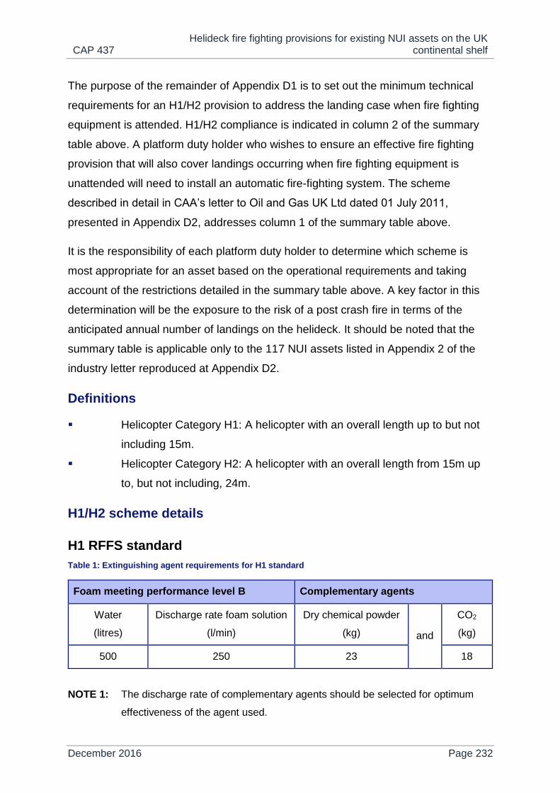
CAP 437 Helideck fire fighting provisions for existing NUI assets on the UK
continental shelf
December 2016 Page 232
The purpose of the remainder of Appendix D1 is to set out the minimum technical
requirements for an H1/H2 provision to address the landing case when fire fighting
equipment is attended. H1/H2 compliance is indicated in column 2 of the summary
table above. A platform duty holder who wishes to ensure an effective fire fighting
provision that will also cover landings occurring when fire fighting equipment is
unattended will need to install an automatic fire-fighting system. The scheme
described in detail in CAA’s letter to Oil and Gas UK Ltd dated 01 July 2011,
presented in Appendix D2, addresses column 1 of the summary table above.
It is the responsibility of each platform duty holder to determine which scheme is
most appropriate for an asset based on the operational requirements and taking
account of the restrictions detailed in the summary table above. A key factor in this
determination will be the exposure to the risk of a post crash fire in terms of the
anticipated annual number of landings on the helideck. It should be noted that the
summary table is applicable only to the 117 NUI assets listed in Appendix 2 of the
industry letter reproduced at Appendix D2.
Definitions
Helicopter Category H1: A helicopter with an overall length up to but not
including 15m.
Helicopter Category H2: A helicopter with an overall length from 15m up
to, but not including, 24m.
H1/H2 scheme details
H1 RFFS standard
Table 1: Extinguishing agent requirements for H1 standard
Foam meeting performance level B Complementary agents
Water
(litres)
Discharge rate foam solution
(l/min)
Dry chemical powder
(kg) and
CO2
(kg)
500 250 23 18
NOTE 1: The discharge rate of complementary agents should be selected for optimum
effectiveness of the agent used.

CAP 437 Helideck fire fighting provisions for existing NUI assets on the UK
continental shelf
December 2016 Page 233
NOTE 2: Dry chemical powder should be of a foam compatible type which is capable of
dealing with Class B fire for liquid hydrocarbons.
NOTE 3: Primary and secondary complementary agents should be delivered from one or
two extinguishers.
Table 1 is predicated on a helicopter with an overall length up to, but not including,
15.0m, having an assumed average fuselage length of 8.5m and an average
fuselage width of 1.5m (to which an additional width factor W1 of 4m is applied).
However, most of the H1 types currently operated on the UKCS have fuselage
lengths and fuselage widths which significantly exceed the H1 mean values derived
from Table 6-4 of the ICAO Heliport Manual (doc. 9261). Therefore it is necessary to
recalculate the critical area assumed for the larger AS365N2/N3 types on the basis
of a helicopter fuselage length of 11.63m and a fuselage width of 2.03m. See Table
2, H1 RFFS Large below.
H1 RFFS large
Table 2: Extinguishing agent requirements for AS365N2 and AS365N3 operations
Foam meeting performance level B Complementary agents
Water
(litres)
Discharge rate foam solution
(l/min)
Dry chemical powder
(kg) and
CO2
(kg)
770 385 23 18
NOTE 1: The discharge rate of complementary agents should be selected for optimum
effectiveness of the agent used.
NOTE 2: Dry chemical powder should be of a foam compatible type which is capable of
dealing with Class B fire for liquid hydrocarbons.
NOTE 3: Primary and secondary complementary agents should be delivered from one or
two extinguishers.
NOTE 4: As an alternative to H1 RFFS large, helidecks operating AS365N2/N3 types may
alternatively select the quantities applicable to H2 RFFS Standard in Table 3.
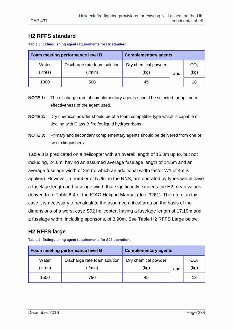
CAP 437 Helideck fire fighting provisions for existing NUI assets on the UK
continental shelf
December 2016 Page 234
H2 RFFS standard
Table 3: Extinguishing agent requirements for H2 standard
Foam meeting performance level B Complementary agents
Water
(litres)
Discharge rate foam solution
(l/min)
Dry chemical powder
(kg) and
CO2
(kg)
1000 500 45 18
NOTE 1: The discharge rate of complementary agents should be selected for optimum
effectiveness of the agent used.
NOTE 2: Dry chemical powder should be of a foam compatible type which is capable of
dealing with Class B fire for liquid hydrocarbons.
NOTE 3: Primary and secondary complementary agents should be delivered from one or
two extinguishers.
Table 3 is predicated on a helicopter with an overall length of 15.0m up to, but not
including, 24.0m, having an assumed average fuselage length of 14.5m and an
average fuselage width of 2m (to which an additional width factor W1 of 4m is
applied). However, a number of NUIs, in the NNS, are operated by types which have
a fuselage length and fuselage width that significantly exceeds the H2 mean values
derived from Table 6-4 of the ICAO Heliport Manual (doc. 9261). Therefore, in this
case it is necessary to recalculate the assumed critical area on the basis of the
dimensions of a worst-case S92 helicopter, having a fuselage length of 17.10m and
a fuselage width, including sponsons, of 3.90m. See Table H2 RFFS Large below.
H2 RFFS large
Table 4: Extinguishing agent requirements for S92 operations
Foam meeting performance level B Complementary agents
Water
(litres)
Discharge rate foam solution
(l/min)
Dry chemical powder
(kg) and
CO2
(kg)
1500 750 45 18

CAP 437 Helideck fire fighting provisions for existing NUI assets on the UK
continental shelf
December 2016 Page 235
NOTE 1: The discharge rate of complementary agents should be selected for optimum
effectiveness of the agent used.
NOTE 2: Dry chemical powder should be of a foam compatible type which is capable of
dealing with Class B fire for liquid hydrocarbons.
NOTE 3: Primary and secondary complementary agents should be delivered from one or
two extinguishers.
Appendix D2
Letter to industry July 2011
Safety Regulation Group
Flight Operations Inspectorate (Helicopters)
Mr Robert Paterson
Health, Safety and Employment Issues Director
Oil and Gas UK Ltd
3rd Floor
62 The Exchange
Market Street
Aberdeen
AB11 5PJ
01 July 2011
Dear Robert,
Helideck Fire-fighting Provisions For Existing Normally Unattended
Installation (NUI) Assets on the United Kingdom Continental Shelf
1. Background to the problem on existing NUI assets on the UKCS
Helidecks in the UK sector of the North Sea are regarded as unlicensed operating
sites. Under Article 96 of the Air Navigation Order (ANO), offshore helicopter
operators are required to satisfy themselves that each helideck they operate to is
‘suitable for the purpose’. Helicopter operators discharge their duty of care through

CAP 437 Helideck fire fighting provisions for existing NUI assets on the UK
continental shelf
December 2016 Page 236
an inspection programme undertaken on their behalf by the Helideck Certification
Agency (HCA), who assesses helidecks and related facilities against standards and
best practice in UK Civil Aviation Publication CAP 437. In essence the HCA
Certification process provides an assurance to the helicopter operators that they are
fulfilling their duty of care under the ANO in only operating to helidecks that are
suitable for the purpose.
Chapter 5 of CAP 437 contains detailed prescriptive requirements for Rescue and
Fire-Fighting Services (RFFS) that are based on international standards and
recommended practices in ICAO Annex 14 Volume II and the Heliport Manual (Doc.
9261). For manned installations and vessels and for new build NUIs, best practice
requirements specify the delivery of foam (e.g. AFFF) at a high application rate and
for an extended duration dispensed from either a Fixed Monitor System (FMS) or
from a Deck Integrated Fire-Fighting System (DIFFS). For a NUI, which is unmanned
for at least the first and last flight of the day, an automatically activated DIFFS ideally
with a passive fire-retarding surface is preferred since this solution provides for
automatic fire suppression and active intervention in the event of a major fire
situation occurring during a take-off or landing where all trained fire crews are
otherwise located in the helicopter.
Historically, for existing NUI facilities on the United Kingdom Continental Shelf
(UKCS), CAP 437 ‘current best practice’ has not been applied for RFFS and, until
recently platform operators selected an RFFS on the basis of United Kingdom
Offshore Operators Association (UKOOA) ‘Guidelines for the Management of
Offshore Helideck Operations’ (Issue 5 - Feb 2005). The ‘UKOOA Guidelines’, which
have been superseded by Oil and Gas UK ‘Guidance for the Management of
Aviation Operations (Issue 6, April 2011 - containing no specific reference to NUI
RFFS), stipulated only minimal fire-fighting media requirements which were broadly
equivalent to scales specified for a low intensity H1 helicopter operation at a
temporary onshore heliport (reference source: CAP 789, Annex 3 to Chapter 21). It
was not intended that such a minimal provision of primary fire-fighting media should
be deemed acceptable for a permanent heliport operation, operating in a remote
location in a hostile environment onto minimum size elevated landing areas, routinely
using helicopters that are not only larger than the H1 category, but also carry more

CAP 437 Helideck fire fighting provisions for existing NUI assets on the UK
continental shelf
December 2016 Page 237
passengers and fuel compared to helicopters typically utilizing the CAP 789 low
intensity requirements. Using the risk assessment elements promulgated in Section
1 of Appendix 1 to this letter, it is not justifiable to select such a reduced level of fire
cover when all these factors are considered together.
It is evident that the current arrangements for RFFS on fixed NUI platforms on the
UKCS are inadequate to address all likely, and reasonably foreseeable, fire
situations that may be encountered during routine offshore helicopter operations. For
this reason, taking account also of concerns raised by the offshore helicopter
operators and the HCA, and with the support of the UK Health and Safety Executive,
CAA has undertaken to conduct a review of the minimum scales of fire fighting
media that would be appropriate for existing NUI assets operating on the UK
Continental Shelf (for a full list of assets see Appendix 2). The following sections
provide detailed outcomes of the review conducted with reference to other sources
of UK best practice (including CAP 168 and CAP 789) and ICAO Annex 14 Volume II
and the Heliport Manual (doc. 9261). Offshore duty holders and helicopter operators
should be aware that the scales presented in this letter are considered to be
minimum requirements for each specific category and, having determined the
appropriate scale, agreed between the platform operator and helicopter operator,
specific NUIs may still decide to select scales of media that are different from those
prescribed, providing they are no lower than the appropriate baseline scale.
2. Determination of an appropriate Rescue and Fire Fighting Service (RFFS)
In the following sections a total of twenty seven separate options are provided for the
consideration of primary media within nine tables promulgated on the basis of the
following:
1) Whether the NUI operation is classed as “Low Intensity”, “Standard
Intensity” or “Higher intensity”. (See definitions in Appendix 1, Section 2.)
2) Whether the largest helicopter operating to the NUI is classed within
“Helicopter Category H1 Large”, “Helicopter Category H2 Medium” or
“Helicopter Category H2 Large”. (See definitions in Appendix 1,
Section 3.)

CAP 437 Helideck fire fighting provisions for existing NUI assets on the UK
continental shelf
December 2016 Page 238
3) Whether the type of foam being discharged meets “ICAO Performance
Level B”, “Performance Level B (Compressed Air Foam System)” or
“ICAO Performance Level C”. (See discussion in Appendix 1, Section 4.)
In all cases the complementary media requirements for gaseous media and Dry
Powder are identical, being based on CAP 437, Chapter 5, Section 4. Likewise the
rescue equipment requirements are the same for every category, being based on
CAP 437, Chapter 5, Section 7 (see also Appendix 1, Section 6). The requirements
for Personal Protective Equipment (PPE) are specified in Appendix 1, Section 7.
In accordance with Appendix 1, Section 5, there is an inbuilt assumption that
whatever method is used for discharging foam to the helideck, the response time
objectives of CAP 437, Chapter 5, Section 2.2 are upheld; such that a delay of less
than 15 seconds should be the operational objective measured from the time the
system is activated to the actual production of foam at the required application rate.
Depending on the overriding fire fighting objectives and assumptions (see Appendix
1, Section 5), the scales are presented to ensure the effective discharge of foam will
last either for a minimum of 2 minutes or 5 minutes.
3. Determining the appropriate scale for each individual NUI operation
On the assumption the largest helicopter operating to a NUI and the Performance
Level of selected foam are fully objectively derived, only the determination of
categorisation of intensity, whether ‘low’, ‘standard’ or ‘higher’, has any degree of
subjectivity attached. However, for each category of operation space for
interpretation is very restricted since the threshold limits on helicopter and passenger
movements, whether determined against a monthly or annual limit and the planned
occupation of the NUI are pre-supposed in the definition. The scales presented for a
low intensity operation, by taking account of the low number of annual movements,
accept that the likelihood of a serious accident occurring with a serious fire ensuing
are comparatively lower. When deciding whether an operation is classed as
‘standard’ or ‘higher’, there should be full recourse to the elements contained in the
helicopter transport risk assessment (see Appendix 1, Section 1) to determine which
of the remaining scales a specific NUI operation will fall into and whether in-fact
there is a case for providing an RFFS which exceeds the baseline limit. There should

CAP 437 Helideck fire fighting provisions for existing NUI assets on the UK
continental shelf
December 2016 Page 239
also be a commitment to reviewing the elements of the helicopter transport risk
assessment on an annual basis to ensure that the scales of RFFS provided for a NUI
continue to be appropriate in accordance with the overall level of risk. Any
conclusions arising from the risk assessment, to support a certain ‘level’ of operation,
should be agreed with the helicopter operator, through the HCA.
4. Methods for primary foam delivery to the helideck
For a NUI, regardless of the policy on manning, there will always be occasions when
a helicopter is required to approach to land or take-off from the installation when it is
unattended. When in an ‘unattended’ mode this assumes there is nobody on the
helideck to operate the foam dispensing equipment in the event of a crash occurring
involving a fire situation. Therefore, it is necessary that any system of foam delivery
is capable of discharging automatically, without the necessity for manual
intervention. CAP 437, Chapter 5 discusses the main options for the effective
discharge of foam to an offshore helicopter landing area and presents specifications
for a Fixed Monitor System (FMS) in Section 2.3 and for a Deck Integrated Fire
Fighting System (DIFFS) in Section 2.9. It is firstly essential for a NUI that where a
DIFFS or an FMS are selected to discharge foam to the landing area they are able to
be immediately and automatically activated in the event of a fire occurring. Likewise
these systems should be able to deliver finished foam to any part of the helideck at
or above the minimum application rate for the range of weather conditions prevalent
for the UKCS. A DIFFS, consisting of a series of pop-up nozzles by design should
more easily achieve the effective and even distribution of foam to all parts of the
landing area because the pattern of ‘pop-up’ sources can be arranged over the
whole landing area (note: individual pop-ups should be sited in such a way to allow
unimpeded right of entry to all access platforms). However, experience from other
offshore sectors in the North Sea operating automatic RFFS on NUIs, has
highlighted also the possibility of a ring-main system (RMS) arrangement, where a
series of nozzles are located equally-spaced right around the perimeter of the
landing area, within prescribed height limits for the 210° sector and 1st segment
limited obstacle sector, so that foam is discharged from all directions around the
helideck. Any system selected should be automatically initiated but with a manual
override function on the NUI and from an adjacent mother platform or from the

CAP 437 Helideck fire fighting provisions for existing NUI assets on the UK
continental shelf
December 2016 Page 240
beach. An FMS will need to have a built in capability to allow for self-oscillation of
monitors.
Whatever method of foam delivery is determined, it is important that the equipment
selected is low maintenance such that any checks prescribed by the manufacturer
can ideally be contained within routine maintenance cycles for the platform. It should
be the objective of platform operators to avoid having to make additional
unscheduled visits to the platform simply to service fire-fighting equipment, which
could have a detrimental effect on the overall risk profile for the platform. Experience
suggests, for example, that selecting pre-mix sealed foam systems, cable of
discharging aspirated or non-aspirated foam will usually require less effort to
maintain.
5. Which installations need to review their current RFFS provision?
Based on information provided by the HCA in interrogating the Helideck Limitations
List (HLL), there are understood to be 116 NUIs operating within the UKCS. These
installations are listed, by region, in Appendix 2. This list includes all NUIs regardless
of their existing RFFS provision. Thus Appendix 2 may be assumed as the definitive
list of installations that need to review their current RFFS provision. The list of 116
NUIs is understood to encompass the assets of approximately 20 offshore duty
holders currently serviced by a range of helicopters from three offshore helicopter
operators. It is important, before any rectification action is implemented, that the
platform operator provides full movement/manning data to the helicopter operator to
facilitate discussion and agree a methodology and programme for any upgrade of
RFFS. Prior to implementation, it will be necessary for the HCA to endorse any
action plan. HCA will wish to ensure that any rectification work, including the physical
location of foam dispensing equipment, does not compromise CAP 437 obstruction
criteria or invalidate any conditions of the current landing area certificate for the
installation.

CAP 437 Helideck fire fighting provisions for existing NUI assets on the UK
continental shelf
December 2016 Page 241
6. Scales of primary and secondary media for existing asset NUIs
Large H1 RFFS Standard Intensity
Extinguishing Agent Requirements
Foam Meeting Performance
Level B
Foam Meeting Performance
Level C
Complementary
Agent
Total
foam
solution
(Litres)
Minimum
discharge
rate of
foam
(L/Min)
Minimum
duration
(Min)
Total
foam
solution
(Litres)
Minimum
discharge
rate of
foam
(L/Min)
Minimum
duration
(Min)
Dry
chemical
powder
(kg)
Gaseous
agent
(kg)
900
(650)
450
(325)
2
(2) 600 300 2 45 18
Notes:
1) Complementary agents should be capable of discharge at an effective rate
delivered from one or two extinguishers.
2) Halon extinguishing agents are no longer prescribed for new installations.
Gaseous agents, including CO2 have replaced them. Gaseous extinguishers
should be provided with a suitable applicator for use on engine fires.
3) Dry Chemical Powder should be a foam compatible type capable of dealing with
Class B fire (or liquid hydrocarbons).
4) Pre-mix foam systems should be fully automatic and be capable of activating
instantaneously in the event of an impact of a helicopter on the helideck where
fire results. The automatic system should dispense aspirated or non-aspirated
foam in a jet or spray pattern.
5) Where a Compressed Air Foam System (CAFS) meeting Performance Level B is
selected in lieu of standard foam, the capacity and application rate may be
accordingly reduced. The minimum requirements for CAFS are shown within the
bracketed values in the above table.

CAP 437 Helideck fire fighting provisions for existing NUI assets on the UK
continental shelf
December 2016 Page 242
Large H1 RFFS Low Intensity
Extinguishing Agent Requirements
Foam Meeting Performance
Level B
Foam Meeting Performance
Level C
Complementary
Agent
Total
foam
solution
(Litres)
Minimum
discharge
rate of
foam
(L/Min)
Minimum
duration
(Min)
Total
foam
solution
(Litres)
Minimum
discharge
rate of
foam
(L/Min)
Minimum
duration
(Min)
Dry
chemical
powder
(kg)
Gaseous
agent
(kg)
150 75 2 120 60 2 45 18
Notes:
1) Complementary agents should be capable of discharge at an effective rate
delivered from one or two extinguishers.
2) Halon extinguishing agents are no longer prescribed for new installations.
Gaseous agents, including CO2 have replaced them. Gaseous extinguishers
should be provided with a suitable applicator for use on engine fires.
3) Dry Chemical Powder should be a foam compatible type capable of dealing with
Class B fire (or liquid hydrocarbons).
4) Premix-foam units may be aspirated or non-aspirated but should be capable of
delivering agent to the seat of the fire.
5) Where a Compressed Air Foam System (CAFS) meeting Performance Level B
selected in lieu of standard foam, the capacity and application rate may be
accordingly reduced. The minimum requirements for CAFS in this case are
assumed to be equivalent to amounts specified for Performance Level C foams.
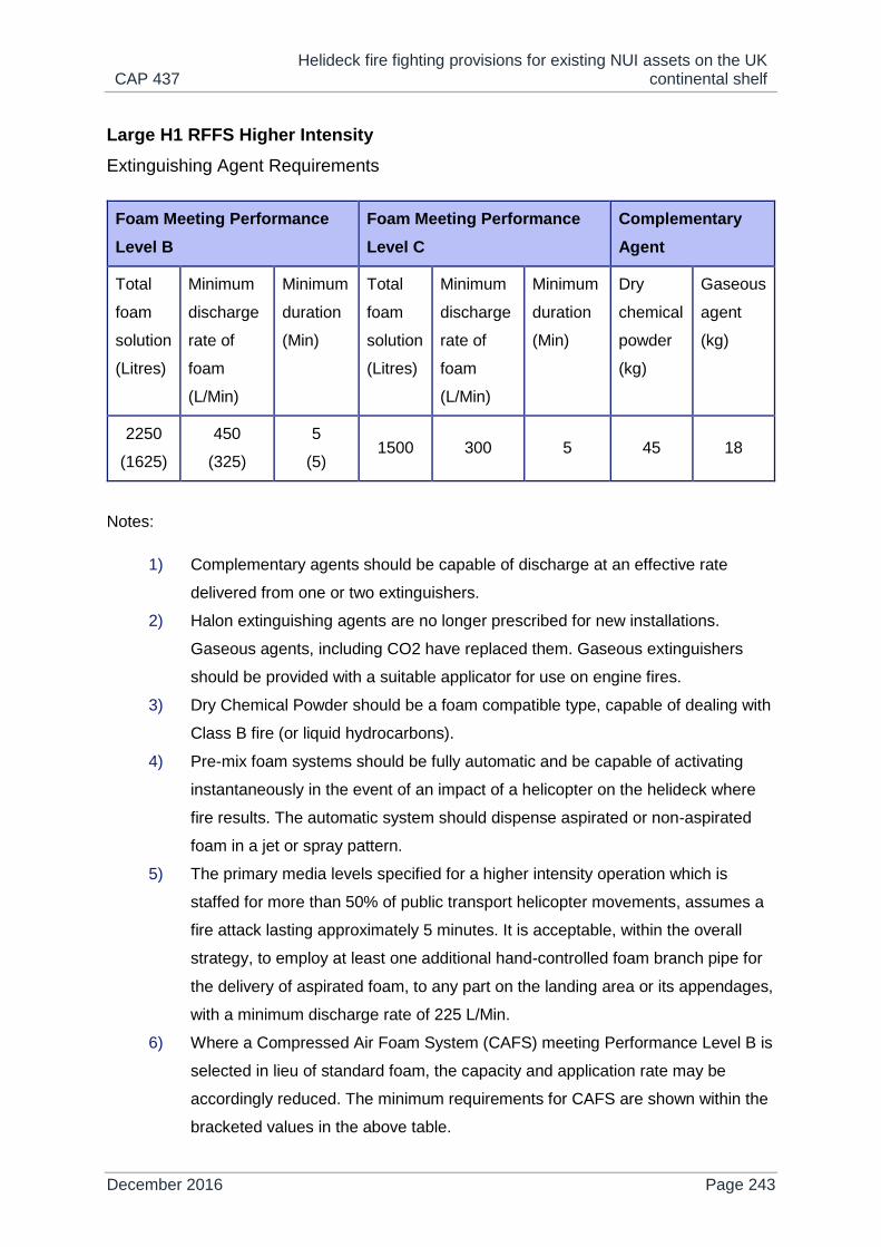
CAP 437 Helideck fire fighting provisions for existing NUI assets on the UK
continental shelf
December 2016 Page 243
Large H1 RFFS Higher Intensity
Extinguishing Agent Requirements
Foam Meeting Performance
Level B
Foam Meeting Performance
Level C
Complementary
Agent
Total
foam
solution
(Litres)
Minimum
discharge
rate of
foam
(L/Min)
Minimum
duration
(Min)
Total
foam
solution
(Litres)
Minimum
discharge
rate of
foam
(L/Min)
Minimum
duration
(Min)
Dry
chemical
powder
(kg)
Gaseous
agent
(kg)
2250
(1625)
450
(325)
5
(5) 1500 300 5 45 18
Notes:
1) Complementary agents should be capable of discharge at an effective rate
delivered from one or two extinguishers.
2) Halon extinguishing agents are no longer prescribed for new installations.
Gaseous agents, including CO2 have replaced them. Gaseous extinguishers
should be provided with a suitable applicator for use on engine fires.
3) Dry Chemical Powder should be a foam compatible type, capable of dealing with
Class B fire (or liquid hydrocarbons).
4) Pre-mix foam systems should be fully automatic and be capable of activating
instantaneously in the event of an impact of a helicopter on the helideck where
fire results. The automatic system should dispense aspirated or non-aspirated
foam in a jet or spray pattern.
5) The primary media levels specified for a higher intensity operation which is
staffed for more than 50% of public transport helicopter movements, assumes a
fire attack lasting approximately 5 minutes. It is acceptable, within the overall
strategy, to employ at least one additional hand-controlled foam branch pipe for
the delivery of aspirated foam, to any part on the landing area or its appendages,
with a minimum discharge rate of 225 L/Min.
6) Where a Compressed Air Foam System (CAFS) meeting Performance Level B is
selected in lieu of standard foam, the capacity and application rate may be
accordingly reduced. The minimum requirements for CAFS are shown within the
bracketed values in the above table.

CAP 437 Helideck fire fighting provisions for existing NUI assets on the UK
continental shelf
December 2016 Page 244
Medium H2 RFFS Standard Intensity
Extinguishing Agent Requirements
Foam Meeting Performance
Level B
Foam Meeting Performance
Level C
Complementary
Agent
Total
foam
solution
(Litres)
Minimum
discharge
rate of
foam
(L/Min)
Minimum
duration
(Min)
Total
foam
solution
(Litres)
Minimum
discharge
rate of
foam
(L/Min)
Minimum
duration
(Min)
Dry
chemical
powder
(kg)
Gaseous
agent
(kg)
1200
(850)
600
(425)
2
(2) 800 400 2 45 18
Notes:
1) Complementary agents should be capable of discharge at an effective rate
delivered from one or two extinguishers.
2) Halon extinguishing agents are no longer prescribed for new installations.
Gaseous agents, including CO2 have replaced them. Gaseous extinguishers
should be provided with a suitable applicator for use on engine fires.
3) Dry Chemical Powder should be a foam compatible type, capable of dealing with
Class B fire (or liquid hydrocarbons).
4) Pre-mix foam systems should be fully automatic and be capable of activating
instantaneously in the event of an impact of a helicopter on the helideck where
fire results. The automatic system should dispense aspirated or non-aspirated
foam in a jet or spray pattern.
5) Where a Compressed Air Foam System (CAFS) meeting Performance Level B is
selected in lieu of standard foam, the capacity and application rate may be
accordingly reduced. The minimum requirements for CAFS are shown within the
bracketed values in the above table.

CAP 437 Helideck fire fighting provisions for existing NUI assets on the UK
continental shelf
December 2016 Page 245
Medium H2 RFFS Low Intensity
Extinguishing Agent Requirements
Foam Meeting Performance
Level B
Foam Meeting Performance
Level C
Complementary
Agent
Total
foam
solution
(Litres)
Minimum
discharge
rate of
foam
(L/Min)
Minimum
duration
(Min)
Total
foam
solution
(Litres)
Minimum
discharge
rate of
foam
(L/Min)
Minimum
duration
(Min)
Dry
chemical
powder
(kg)
Gaseous
agent
(kg)
310 155 2 220 110 2 45 18
Notes:
1) Complementary agents should be capable of discharge at an effective rate
delivered from one or two extinguishers.
2) Halon extinguishing agents are no longer prescribed for new installations.
Gaseous agents, including CO2 have replaced them. Gaseous extinguishers
should be provided with a suitable applicator for use on engine fires.
3) Dry Chemical Powder should be a foam compatible type, capable of dealing with
Class B fire (or liquid hydrocarbons).
4) Premix-foam units may be aspirated or non-aspirated but should be capable of
delivering agent to the seat of the fire.
5) Where a Compressed Air Foam System (CAFS) meeting Performance Level B is
selected in lieu of standard foam, the capacity and application rate may be
accordingly reduced. The minimum requirements for CAFS in this case are
assumed to be equivalent to amounts specified for Performance Level C foams.

CAP 437 Helideck fire fighting provisions for existing NUI assets on the UK
continental shelf
December 2016 Page 246
Medium H2 RFFS Higher Intensity
Extinguishing Agent Requirements
Foam Meeting Performance
Level B
Foam Meeting Performance
Level C
Complementary
Agent
Total
foam
solution
(Litres)
Minimum
discharge
rate of
foam
(L/Min)
Minimum
duration
(Min)
Total
foam
solution
(Litres)
Minimum
discharge
rate of
foam
(L/Min)
Minimum
duration
(Min)
Dry
chemical
powder
(kg)
Gaseous
agent
(kg)
3000
(2125)
600
(425)
5
(5) 2000 400 5 45 18
Notes:
1) Complementary agents should be capable of discharge at an effective rate
delivered from one or two extinguishers.
2) Halon extinguishing agents are no longer prescribed for new installations.
Gaseous agents, including CO2 have replaced them. Gaseous extinguishers
should be provided with a suitable applicator for use on engine fires.
3) Dry Chemical Powder should be a foam compatible type, capable of dealing with
Class B fire (or liquid hydrocarbons).
4) Pre-mix foam systems should be fully automatic and be capable of activating
instantaneously in the event of an impact of a helicopter on the helideck where
fire results. The automatic system should dispense aspirated or non-aspirated
foam in a jet or spray pattern.
5) The primary media levels specified for a higher intensity operation which is
staffed for more than 50% of public transport helicopter movements, assumes a
fire attack lasting approximately 5 minutes. It is acceptable, within the overall
strategy, to employ at least one additional hand-controlled foam branch pipe for
the delivery of aspirated foam, to any part on the landing area or its appendages,
with a minimum discharge rate of 225 L/Min.
6) Where a Compressed Air Foam System (CAFS) meeting Performance Level B is
selected in lieu of standard foam, the capacity and application rate may be
accordingly reduced. The minimum requirements for CAFS are shown within the
bracketed values in the above table.

CAP 437 Helideck fire fighting provisions for existing NUI assets on the UK
continental shelf
December 2016 Page 247
Large H2 RFFS Standard Intensity
Extinguishing Agent Requirements
Foam Meeting Performance
Level B
Foam Meeting Performance
Level C
Complementary
Agent
Total
foam
solution
(Litres)
Minimum
discharge
rate of
foam
(L/Min)
Minimum
duration
(Min)
Total
foam
solution
(Litres)
Minimum
discharge
rate of
foam
(L/Min)
Minimum
duration
(Min)
Dry
chemical
powder
(kg)
Gaseous
agent
(kg)
1500
(1080)
750
(540)
2
(2) 1050 525 2 45 18
Notes:
1) Complementary agents should be capable of discharge at an effective rate
delivered from one or two extinguishers.
2) Halon extinguishing agents are no longer prescribed for new installations.
Gaseous agents, including CO2 have replaced them. Gaseous extinguishers
should be provided with a suitable applicator for use on engine fires.
3) Dry Chemical Powder should be a foam compatible type, capable of dealing with
Class B fire (or liquid hydrocarbons).
4) Pre-mix foam systems should be fully automatic and be capable of activating
instantaneously in the event of an impact of a helicopter on the helideck where
fire results. The automatic system should dispense aspirated or non-aspirated
foam in a jet or spray pattern.
5) Where a Compressed Air Foam System (CAFS) meeting Performance Level B is
selected in lieu of standard foam, the capacity and application rate may be
accordingly reduced. The minimum requirements for CAFS are shown within the
bracketed values in the above table.

CAP 437 Helideck fire fighting provisions for existing NUI assets on the UK
continental shelf
December 2016 Page 248
Large H2 RFFS Low Intensity
Extinguishing Agent Requirements
Foam Meeting Performance
Level B
Foam Meeting Performance
Level C
Complementary
Agent
Total
foam
solution
(Litres)
Minimum
discharge
rate of
foam
(L/Min)
Minimum
duration
(Min)
Total
foam
solution
(Litres)
Minimum
discharge
rate of
foam
(L/Min)
Minimum
duration
(Min)
Dry
chemical
powder
(kg)
Gaseous
agent
(kg)
350 175 2 250 125 2 45 18
Notes:
1) Complementary agents should be capable of discharge at an effective rate
delivered from one or two extinguishers.
2) Halon extinguishing agents are no longer prescribed for new installations.
Gaseous agents, including CO2 have replaced them. Gaseous extinguishers
should be provided with a suitable applicator for use on engine fires.
3) Dry Chemical Powder should be a foam compatible type, capable of dealing with
Class B fire (or liquid hydrocarbons).
4) Premix-foam units may be aspirated or non-aspirated but should be capable of
delivering agent to the seat of the fire.
5) Where a Compressed Air Foam System (CAFS) meeting Performance Level B is
selected in lieu of standard foam, the capacity and application rate may be
accordingly reduced. The minimum requirements for CAFS in this case are
assumed to be equivalent to amounts specified for Performance Level C foams.

CAP 437 Helideck fire fighting provisions for existing NUI assets on the UK
continental shelf
December 2016 Page 249
Large H2 RFFS Higher Intensity
Extinguishing Agent Requirements
Foam Meeting Performance
Level B
Foam Meeting Performance
Level C
Complementary
Agent
Total
foam
solution
(Litres)
Minimum
discharge
rate of
foam
(L/Min)
Minimum
duration
(Min)
Total
foam
solution
(Litres)
Minimum
discharge
rate of
foam
(L/Min)
Minimum
duration
(Min)
Dry
chemical
powder
(kg)
Gaseous
agent
(kg)
3750
(2700)
750
(540)
5
(5) 2625 525 5 45 18
Notes:
1) Complementary agents should be capable of discharge at an effective rate
delivered from one or two extinguishers.
2) Halon extinguishing agents are no longer prescribed for new installations.
Gaseous agents, including CO2 have replaced them. Gaseous extinguishers
should be provided with a suitable applicator for use on engine fires.
3) Dry Chemical Powder should be a foam compatible type, capable of dealing with
Class B fire (or liquid hydrocarbons).
4) Pre-mix foam systems should be fully automatic and be capable of activating
instantaneously in the event of an impact of a helicopter on the helideck where
fire results. The automatic system should dispense aspirated or non-aspirated
foam in a jet or spray pattern.
5) The primary media levels specified for a higher intensity operation which is
staffed for more than 50% of public transport helicopter movements, assumes a
fire attack lasting approximately 5 minutes. It is acceptable, within the overall
strategy, to employ at least one additional hand-controlled foam branch pipe for
the delivery of aspirated foam, to any part on the landing area or its appendages,
with a minimum discharge rate of 225 L/Min.
6) Where a Compressed Air Foam System (CAFS) meeting Performance Level B is
selected in lieu of standard foam, the capacity and application rate may be
accordingly reduced. The minimum requirements for CAFS are shown within the
bracketed values in the above table.

CAP 437 Helideck fire fighting provisions for existing NUI assets on the UK
continental shelf
December 2016 Page 250
7. Timescales for rectification action
NUIs projects that are classed as ‘higher intensity’ operations should be assigned
the highest priority and any necessary upgrade of RFFS should be completed within
three years from the date of this letter. For all other operations, with those classed
as ‘standard intensity’ receiving priority over those classed as ‘low intensity’,
rectification should be completed within six years with an absolute cut-off for
compliance of 30 June 2017.
8. Request to disseminate to industry asset duty holders
I would be grateful if you could disseminate this letter amongst your members. This
letter is copied for information to the offshore helicopter operators, the Helideck
Certification Agency and the Health and Safety Executive, Offshore Safety Division.
Yours sincerely,
Kevin P Payne
Flight Standards Officer
Flight Operations Inspectorate (Helicopters)
Appendix 1: Further explanatory guidance and background for
definitions and interpretations disseminated in the main letter
1. Elements to be considered for the helicopter transport risk analysis
1) The number of planned helicopter movements and frequency of
movements.
2) The number of passengers landing and taking off from the NUI –
whether or not the particular NUI is the final planned outbound or
inbound destination for passengers.
3) The types of helicopters utilised and specific hazards (e.g.
construction, fuel load).
CAP 437 Helideck fire fighting provisions for existing NUI assets on the UK
continental shelf
December 2016 Page 251
4) The characteristics of the helideck and platform general arrangement
(e.g. helideck access).
5) The largest helicopter authorised to operate to the helideck.
6) The level of planned occupation of the NUI including the off-shift
policy.
7) Whether the helideck is attended or unattended during helicopter
movements.
2. Definitions for low, standard and higher intensity operations
Low intensity operations: Low intensity operations are regarded as those
installations where the planned number of annual public transport helicopter
movements does not exceed 10 and/or where the annual number of passengers
landing on and taking off from the installation does not exceed 50. For an installation
to qualify as a low intensity operation there should be no planned off-shift stays.
Standard intensity operations: Standard intensity operations are regarded as
those where the planned number of annual public transport helicopter movements
and/or the annual number of passengers landing on and taking off from the
installation exceed the threshold levels prescribed for low intensity operations but
where the planned number of movements are not expected to exceed 10 public
transport helicopter movements per month and/or the number of passengers landing
on and taking off from the installation is not expected to exceed 50 per month. Within
this category, helicopters may be used to support regular visits to the installation
provided that no off-shift stays are planned.
Higher intensity operations: Higher intensity operations should include any
installations where off-shift stays are planned regardless of the frequency or duration
of stays. In addition where helicopter operations are engaged to support frequent
visits to an installation, but with no planned off-shift stays, these should also be
included within the minimum requirements prescribed for higher intensity operations
if the number of public transport helicopter movements exceeds 10 per month and/or
the number of passengers landing on and taking off from the installation exceeds 50
per month.
Notes:
CAP 437 Helideck fire fighting provisions for existing NUI assets on the UK
continental shelf
December 2016 Page 252
1) A movement is defined as one take-off or one landing. A helicopter landing or
taking off with no passengers on board may be regarded as a non-public
transport (positioning) flight.
2) Installations with planned off-shift stays should automatically consider at least
the minimum requirements prescribed for higher intensity operations.
3) Passenger numbers should take account of all persons on board the helicopter,
excluding aircrew, at the point of touchdown to land or on take-off from the
installation.
4) With the acceptance of the helicopter operator figures for projected future
helicopter movements and passenger numbers may be derived on the basis of
data collected for an installation over the previous three year period provided
there are no foreseeable changes in operating practices which might result in a
significant increase in one or either assessment parameter determining threshold
limits.
5) The helicopter operator should be consulted on any queries that may arise for an
interpretation of frequency of visits.
3. Definitions and interpretations for re-defining Helicopter fire fighting
categorisation
ICAO Annex 14 Volume II provides definitions for H1, H2 and H3 as follows:
Helicopter Category H1: A helicopter with an overall length up to but not
including 15m.
Helicopter Category H2: A helicopter with an overall length from 15m up
to but not including 24m.
Helicopter Category H3: A helicopter with an overall length from 24m up
to but not including 35m.
Note: H3 may be discounted on the basis there are no H3 helicopters operating to
NUIs on the UKCS.
For the purpose of calculating the critical area for helicopter fire fighting category H1,
H2 and H3 for a heliport, the ICAO Heliport Manual applies critical area calculations
based on average fuselage dimensions for each category (to form a rectangular area
of protection around a generic helicopter). For helicopter operations to NUIs, nearly
all the helicopters being operated have fuselage dimensions that are appreciably

CAP 437 Helideck fire fighting provisions for existing NUI assets on the UK
continental shelf
December 2016 Page 253
greater than the average fuselage dimensions assumed for each generic category.
Therefore, to ensure the critical area calculation addresses the fuselage dimensions
for a range of helicopters likely to operate to a NUI helideck, critical area
assumptions have been determined using the ‘worst case’ helicopter type within a
series of operating helicopters on the following basis:
Helicopter Category H1 Large: includes all Dauphin AS 365 variants.
Helicopter Category H2 Medium: includes all variants of the S76, AW
139 and the EC 155.
Helicopter Category H2 Large: includes EC 175, AS 332 L1 and L2, EC
225, S92, S61 and Bell 214.
For category H2 medium, the [bold] AW 139 is determined to be the worst case
helicopter with the largest dimensional combination of fuselage length x width (plus
4m) and for category H2 Large, the [bold] S92 is assumed to be the worst case
helicopter. Where NUIs adopt levels in accordance with these helicopter definitions it
may be automatically assumed that any other helicopters listed in the same
category, or in a lower category (where applicable), are also authorised to use the
helideck from the perspective of the adequacy of RFFS. However, no account is
taken of further additional types which might be introduced to service NUI operations
in the future.
4. Rationale for minimum application rates assumptions
According to ICAO Annex 14 Volume II and the Heliport Manual (Doc. 9261) any
foam concentrate used for heliport fire fighting should at least meet ICAO
Performance Level B (i.e. Performance Level A foams are not permitted). For
Performance Level B foam the standard application rate is 5.5 (L/min)/m2 based on
the assumed critical area (m2). This is the minimum application rate applied
throughout this document for ‘standard’ Performance Level B foam (e.g. AFFF,
FFFP). Advancements in foam technologies mean that the aviation sector is now
making increasing use of Compressed Air Foam Systems (CAFS). Due to the
superior fire suppression qualities of CAFS, it has been demonstrated through
comparative test programmes that where a Performance Level B Compressed Air
Foam System is utilised, the minimum application rate of the foam may be reduced

CAP 437 Helideck fire fighting provisions for existing NUI assets on the UK
continental shelf
December 2016 Page 254
to no less than 4.0 (L/min)/m². In addition it is anticipated ICAO Annex 14 Volume I
will in future sanction the use of Performance Level C foams for aircraft fire fighting.
In a similar way that Performance Level B foam is more efficient than a Level A
foam, which is reflected in a lower application rate requirement, so Level C foam is
proven to be more effective than a comparative Level B foam. Consequently
provision is made in the tables for the use of Performance Level C foam discharged
with a minimum application rate of not less than 3.75 (L/min)/m². These
developments effectively give offshore duty holders much more flexibility to select
foam systems based on the performance of each type of foam on the understanding
that the more effective the foam technology, the less overall foam solution will be
required to achieve the same results. This flexibility is especially useful for platforms
where additional topside weight and storage capability are most critical.
Note – ICAO Level C Foam: A new standard for fire fighting foam is currently proposed and
proceeding through the International Civil Aviation Organisation (ICAO) to be
published in Annex 14 (Volume I) to the Convention on International Civil
Aviation. The expected date for applicability of this amendment is 15 November
2012. The standard will require an improvement in fire fighting performance and
foam manufacturers will be working to develop foams to meet this new standard.
As with any product with an environmental impact, a balance will need to be
made between safety, cost and the effects on the environment.
5. Rationale for response time objective and discharge duration
requirements
It is proposed that for an installation with RFFS which is unattended for at-least 50%
of the time during public transport helicopter movements, a 2-minute minimum
discharge capability is permitted. This assumes the automatic application of primary
media at the required rate within 15 seconds of an accident occurring with the
objective that any fire should be brought “under control” within 1-minute from
commencing the discharge of primary foam media, thereby allowing the occupants of
the helicopter, during a survivable accident, the opportunity to escape from the
helicopter and clear the helideck environs, with the option for abandoning the
platform if necessary.
CAP 437 Helideck fire fighting provisions for existing NUI assets on the UK
continental shelf
December 2016 Page 255
For a platform to be classed as a higher intensity operation there is a good likelihood
that the RFFS will be attended for more than 50% of public transport helicopter
movements, such that there is a reasonable expectation that trained fire fighters will
be present to tackle any fire scenario that might be expected to occur on the helideck
including a helicopter crash with fire. In this case, having an additional 3 minutes of
media discharge (5 minutes instead of 2 minutes), there is opportunity for a
prolonged manual intervention to confront a fire situation and, having controlled the
fire with the objective of saving lives, to ensure that the fire is completely
extinguished, likely with media in hand to provide further post fire protection. In
consideration of these additional objectives, where the discharge duration for the
primary extinguishing agent for a higher intensity operation is increased from 2 to 5
minutes, it is acceptable that some of the additional media could be delivered from
one or two hand-controlled foam branch pipes to allow delivery of foam to areas
which might otherwise be inaccessible to fixed systems – see main letter and section
entitled “Methods of foam delivery to the helideck”.
For platforms classed as Low Intensity Operations the provision for an automated
means of foam delivery system may be waived providing the Platform Safety Case
records and justifies the non-availability of an automated fire-fighting protection
system in the event of an accident occurring, which results in a major fire ensuing
during a landing or take-off when the platform is unattended. During times when the
platform is attended trained fire and rescue crews should have at their disposal
appropriate equipment including primary and secondary media for the purpose of
saving life (in the event of an accident occurring) and/or for mopping up incidents
involving minor fires (e.g. an engine fire). The level of media prescribed is not
intended to provide for an extended and sustained attack on a major helicopter
incident with fire.
6. Rescue equipment
Rescue equipment should be provided in accordance with CAP 437, Chapter 5,
Section 7 and should be provided for all NUI assets regardless of their classification.
7. Personal Protective Equipment (PPE)

CAP 437 Helideck fire fighting provisions for existing NUI assets on the UK
continental shelf
December 2016 Page 256
All responding RFF personnel should be provided with appropriate PPE to allow
them to carry out their duties in an effective manner. Sufficient personnel to operate
the RFF equipment effectively, when an installation is attended, should be dressed in
suitable protective clothing.
For the selection of appropriate PPE, account should be taken of the HSE Personal
Protective Equipment at Work Regulations (PPEWR) and the Provision and Use of
Work Equipment Regulations (PUWER) which require equipment to be suitable and
safe for intended use, maintained in a safe condition and, where appropriate,
inspected to ensure it remains fit for purpose. In addition equipment should only be
used by personnel who have received adequate information, instruction and training.
PPE should be accompanied by suitable safety measures e.g. protective devices,
markings and warnings. A responsible person should be appointed to ensure all PPE
is installed, stored, checked and maintained in accordance with manufacturers’
instruction.
Appropriate PPE should be determined through a process of risk assessment
acceptable to the HCA and the offshore helicopter operators.
Appendix 2: Normally Unattended Installations – list of existing NUI
assets on the UKCS by region, requiring a review of Rescue and
Fire Fighting
Northern North Sea (10)
Beatrice B
Beatrice C
Beryl SPM 2
Beryl SPM 3
BP Unity
Erskine
Franklin
Goldeneye
Jade
Mungo
UK West Coast (10)
Calder
DP-3
DP-4
DP-6
DP-8
DPPA
Hamilton
Hamilton North
Lennox
Millorn West
Southern North Sea (96)
23E
49-30A (Davy)
Amethyst A1D
Amethyst A2D
Amethyst B1D
Amethyst C1D
Anglia A
Audrey WD
Audrey XW
Babbage

CAP 437 Helideck fire fighting provisions for existing NUI assets on the UK
continental shelf
December 2016 Page 257
Barque PB
Barque PL
Boulton BM
Caister
Carrack QA
Cavendish
Chiswick
Covette
Europa
Excalibur
Galahad
Galleon PG
Galleon PN
Ganymede
Garrow
Grove
Guinevere
Hewett 48/29B
Hewett 48/29C
Hewett 48/29Q
Hewett 52/5A
Hoton
Hyde
Inde 18A
Inde 18B
Inde 23C
Inde 23D
Kelvin
Ketch
Kilmar
Lancelot
Leman 27B
Leman 27C
Leman 27D
Leman 27E
Leman 27F
Leman 27G
Leman 27H
Leman 27J
Malory
Markham ST-1
Mirnas
Minerva
Munro
Neptune
North Valiant SP
Pickerill A
Pickerill B
Ravenspurn North ST2
Ravenspurn North ST3
Ravenspurn RA
Ravenspurn RB
Ravenspurn RC
Saturn
Schooner
Sean R
Shell B
Shell BT
Shell C
Shell D
Shell E
Shell F
Shell Lernan G
South Valiant
Tethys
Trent
Tyne
Vampire
Vanguard QD
Victor JD
Viking AR
Viking CD
Viking DD
Viking ED
Viking GD
Viking HD
Viking KD
Viking LD
Viscount
Vulcan 2 UR
Vulcan RD
Waveny
Wenlock
West Sole B
West Sole C
Windernere
Total No. NUIs = 116
+ 1 Camelot A (subsequently notified)

CAP 437 Additional guidance relating to the provision of meteorological information
from offshore installations
December 2016 Page 258
Appendix E
Additional guidance relating to the provision of meteorological information from offshore installations
Introduction
E.1 This Appendix provides additional guidance on the provision of
meteorological information from offshore installations, which is detailed in
Chapter 6.
E.2 The provision of meteorological information for the safety, efficiency and
regulation of international air navigation is subject to international
standards and recommended practices described in Annex 3 to the
Chicago Convention published by ICAO. Requirements for observer
training and observing accuracy are set out by the United Nation's World
Meteorological Organization (WMO).
E.3 CAP 746 Meteorological Observations at Aerodromes provides the policy
and guidance related to the provision of meteorological information at
aerodromes in the UK. To ensure compliance with these requirements,
and to standardise the provision of meteorological information provided,
where practicable CAP 746 applies. Specific exceptions are detailed
below.
Contents and standardisation of the weather reports issued by each offshore installation
Wind
E.4 To be reported as per CAP 746 (Chapter 4).

CAP 437 Additional guidance relating to the provision of meteorological information
from offshore installations
December 2016 Page 259
NOTE 1: The wind speed and direction reported should always be taken directly from the
automated information supplied by the anemometer even where these may be
sheltered.
NOTE 2: Gusts may be reported in pre-flight weather reports regardless of the difference
between mean wind speed and gust speed but should always be reported if they
exceed the mean wind speed as specified in CAP 746 (Chapter 4).
Visibility
E.5 To be reported in metres, as per CAP 746 (Chapter 4). The visibility
reported is the minimum visibility. Visibilities greater than 10 km should be
reported as 9999.
Lightning
E.6 When lightning is observed, it should be included in the report.
Present weather
E.7 Only the following weather phenomena are required to be reported:
Thunderstorm (no precipitation)
Thunderstorm with rain
Thunderstorm with rain and snow
Thunderstorm with snow
Thunderstorm with hail
Thunderstorm with heavy rain
Thunderstorm with heavy rain and snow
Thunderstorm with heavy snow
Thunderstorm with heavy hail
Thunderstorm in the vicinity
Drizzle
Heavy drizzle
Rain
Heavy rain
Rain and drizzle
Heavy rain and drizzle
Freezing rain
Heavy freezing rain
Freezing drizzle
Heavy freezing drizzle
Snow grains
Snow
Heavy snow
Rain and snow
Heavy rain and snow
Ice pellets
Rain shower
Heavy rain shower
Rain and snow shower
Heavy rain and snow shower
Snow shower
Heavy snow shower
Hail shower

CAP 437 Additional guidance relating to the provision of meteorological information
from offshore installations
December 2016 Page 260
Heavy hail shower
Shower in the vicinity
Fog
Freezing fog
Fog patches
Partial fog
Shallow fog
Fog in the vicinity
Haze
Mist
Smoke
Dust
Sea spray
Squall
Funnel cloud
Volcanic ash
Blowing sand
Sandstorm
NOTE 1: Guidance on the reporting of these present weather phenomena is as per CAP
746 (Chapter 4).
NOTE 2: No coding is required since the report is to be written in plain language.
NOTE 3: If none of the above is observed then the entry for Present Weather will be Nil.
NOTE 4: Where appropriate up to three of the above phenomena may be reported.
Reporting of fog
E.8 If there is fog within a 1000m and the visibility is <1000m in one or more
directions then Fog (or Freezing Fog) should be reported as the Present
Weather. If there is fog within a 1000m and the visibility is <1000m in only
some directions the Fog (or Freezing Fog) should be reported as Present
Weather and an annotation should be made in the remarks box denoting
the type of fog (i.e. Partial Fog (fog bank) or Fog Patches). Shallow Fog
will be presented as the Present Weather if it is observed, whether patchy
or as a continuous layer, within 1000m below helideck level (the visibility
within the shallow fog will be 1000m or more). Where there is no fog
within a 1000m, but fog can be seen within 8km, the Present Weather
should be reported as Fog in the vicinity with a note in the remarks section
indicating the presence of Shallow Fog, Partial Fog (fog bank) or Fog
Patches Additionally the remarks section could also include a direction in
which the fog is seen, e.g. Partial Fog to East.
CAP 437 Additional guidance relating to the provision of meteorological information
from offshore installations
December 2016 Page 261
Cloud
E.9 Cloud amount is reported as:
Few (FEW);
Scattered (SCT);
Broken (BKN); and
Overcast (OVC);
as per CAP 746 (Chapter 4). Sky Obscured (VV///) and No Significant
Cloud (NSC) should also be reported.
E.10 Cumulonimbus (CB) or Towering Cumulus (TCU) should be added to the
report when present.
E.11 Cloud heights are to be reported in plain language in feet AMSL, rounded
down to the nearest 100 ft. There is no requirement to report cloud above
5,000 ft unless CB or TCU is present.
E.12 A maximum of four cloud groups can be reported.
CAVOK (Cloud and Visibility OK)
E.13 To be reported as per CAP 746 (Chapter 4). When appropriate to do so,
CAVOK should be reported as Present Weather.
Air temperature and dew point
E.14 To be reported as per CAP 746 (Chapter 4).
QNH and QFE (atmospheric pressure)
E.15 To be reported as per CAP 746 (Chapter 4).
Significant wave height
E.16 Where sensors are deployed for the measurement of Significant Wave
Height the information should be included in the report. The Wave Height
should be reported to one decimal place, e.g. 7.6 m.
CAP 437 Additional guidance relating to the provision of meteorological information
from offshore installations
December 2016 Page 262
NOTE: Only wave height information from sensors deployed at the installation
concerned should be reported.
Pitch, roll, helideck inclination and significant heave rate
E.17 Current good practice is provided in CAP 437, Chapter 6.
Remarks
E.18 This part of the form can be used to report additional Meteorological-
related information that may assist the helicopter crew, e.g. Lightning
seen at 12.30, Fog bank to SW, or Heavy Rain shower at 16.20. When a
sensor is unavailable and an estimate has been made of the conditions, a
note should be recorded in the Remarks section including the original date
that the sensor became unserviceable.
Missing or unavailable information
E.19 Exceptionally, when a sensor is unserviceable and the contingency device
is not able to be accessed, or is also unserviceable, the report should be
annotated with N/A indicating that the information is not available and the
original date that the primary sensor became unserviceable should be
recorded in the Remarks section.
Example offshore report
E.20 A pre-flight weather report form template is given below that should be
used to supply the relevant information. An example report is also
provided (see Figure 2).

CAP 437 Additional guidance relating to the provision of meteorological information
from offshore installations
December 2016 Page 263
Figure 1: Offshore weather report form - Template

CAP 437 Additional guidance relating to the provision of meteorological information
from offshore installations
December 2016 Page 264
Figure 2: Offshore weather report - Example

CAP 437 Additional guidance relating to the provision of meteorological information
from offshore installations
December 2016 Page 265
Definition of an offshore meteorological observer
E.21 Offshore Meteorological Observer: any competent person who makes a
weather observation or who updates a weather observation which is
provided either as a Pre-Flight Weather Report or as a Radio Message to
a helicopter en route to a fixed or floating offshore facility. Such personnel
should be trained and qualified as a Meteorological Observer for Offshore
Helicopter Operations.
NOTE 1: Platform operators should allocate sufficient time resources to the meteorological
observing staff to enable them to carry out observing duties.
NOTE 2: Meteorological Observers should be located in a position that enables them to
assess the weather from an outside observing position, whenever possible, in
order to validate that observations are representative of the installation and its
vicinity.
E.22 Master Mariners who have been issued with a Marine Coastguard Agency
(MCA) Certificate Officer of the Watch (OOW) or equivalent qualification
and are regularly providing WMO-compliant ship meteorological
observations may be considered competent to provide weather
observations for offshore helicopter operations. However, Master Mariners
are recommended to become certificated Offshore Met Observers in order
to ensure that the information being provided specifically to helicopter
operators is to the standards required since there are a number of
important differences compared to WMO ship observations.
Applicability of meteorological equipment to helideck categories
E.23 The following categories of helideck should meet the requirements for
Meteorological instrumentation given in CAP 437:
fixed installations (HLL Code A);

CAP 437 Additional guidance relating to the provision of meteorological information
from offshore installations
December 2016 Page 266
semi-submersible, e.g. semi-submersible crane and lay barges,
purpose-built monohull Floating Storage Units (FSUs) and
production vessels (HLL Code 1); and
large ships, e.g. drill ships, Floating Production Storage and
Offloading units (FPSOs) whether purpose-built or converted oil
tankers, non-semi-submersible and lay barges and self-elevating rigs
on the move (HLL Code 1).
NOTE: Due to less frequent helicopter operations, the weather reports for smaller ships,
e.g. Diving Support Vessels (DSVs), support and seismic vessels and tankers
(HLL Codes 2 and 3), are required to contain only wind, pressure, air
temperature and dew point temperature information. For the purposes of this
note, 'less frequent helicopter operations' may be interpreted to mean 'not
exceeding 12 landings per year'. Similarly, where weather information is being
provided by NUIs, the weather report should include (as a minimum) wind,
pressure, air temperature and dew point temperature information. Following
notification to the Southern Aviation Safety Forum (SASF), only specific NUIs in
the southern North Sea are required to provide the information noted above.
Design, siting and back-up requirements for meteorological equipment installed in offshore installations
Wind speed and direction
E.24 See CAP 746, Chapter 7.
Performance
E.25 The wind measuring equipment should provide an accurate and
representative measurement of wind speed and direction.
E.26 Wind direction data should be oriented with respect to True North.
E.27 The wind speed measurement should be to an accuracy of within ±1 kt, or
±10% for wind speeds in excess of 10 kt, of the actual wind speed
(whichever is the greater), over the following ranges:

CAP 437 Additional guidance relating to the provision of meteorological information
from offshore installations
December 2016 Page 267
Table 1: Tolerance values of sensors and equipment - Wind speed
Variable In-tolerance operating range Recoverable range
Wind speed 0 to 100 kt 0 to 130 kt
E.28 With wind speeds in excess of 2 kt, the wind direction system should be
capable of producing an overall accuracy better than ±10°. The sensor
should be sampled at a minimum rate of four times every second. Where
wind systems measure the gust, the equipment should calculate the
three-second gust as a rolling average of the wind speed samples.
E.29 The equipment should be capable of producing two- and ten-minute
rolling averages of the wind speed and direction. The algorithms used for
the production of such averages should be defined. The average direction
displayed should take regard of the numerical discontinuity at North.
Back-up
E.30 Alternative anemometry meeting the siting requirements specified below
and in Chapter 6 should be provided.
NOTE: It is recommended that a hand-held anemometer is used as a back-up in case of
the failure or unavailability of the automated sensors; any readings that are taken
should be taken from the centre of the helideck. The pilot should be advised that
a hand-held anemometer has been used to estimate the wind speed and a
remark should be added to the offshore weather report form.
Siting
E.31 This is detailed in Chapter 6, paragraph 6.13, Assessment of Wind Speed
and Direction.
E.32 The aim is to site the wind sensor in such a position to capture the
undisturbed flow. It is recommended that the wind sensor be mounted at
the highest practical point, e.g. on the drilling derrick or the
telecommunications mast. However, it should be noted that regular
servicing is required and for that reason the flare stack should not be
used. If no suitable mast is available then a specific wind sensor mast
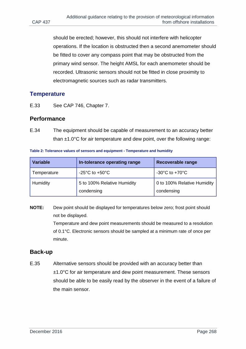
CAP 437 Additional guidance relating to the provision of meteorological information
from offshore installations
December 2016 Page 268
should be erected; however, this should not interfere with helicopter
operations. If the location is obstructed then a second anemometer should
be fitted to cover any compass point that may be obstructed from the
primary wind sensor. The height AMSL for each anemometer should be
recorded. Ultrasonic sensors should not be fitted in close proximity to
electromagnetic sources such as radar transmitters.
Temperature
E.33 See CAP 746, Chapter 7.
Performance
E.34 The equipment should be capable of measurement to an accuracy better
than ±1.0°C for air temperature and dew point, over the following range:
Table 2: Tolerance values of sensors and equipment - Temperature and humidity
Variable In-tolerance operating range Recoverable range
Temperature -25°C to +50°C -30°C to +70°C
Humidity 5 to 100% Relative Humidity
condensing
0 to 100% Relative Humidity
condensing
NOTE: Dew point should be displayed for temperatures below zero; frost point should
not be displayed.
Temperature and dew point measurements should be measured to a resolution
of 0.1°C. Electronic sensors should be sampled at a minimum rate of once per
minute.
Back-up
E.35 Alternative sensors should be provided with an accuracy better than
±1.0°C for air temperature and dew point measurement. These sensors
should be able to be easily read by the observer in the event of a failure of
the main sensor.
CAP 437 Additional guidance relating to the provision of meteorological information
from offshore installations
December 2016 Page 269
Siting
E.36 Temperature and humidity sensors should be exposed in an instrument
housing (e.g. Stevenson Screen), which provides protection from
atmospheric radiation and water droplets as either precipitation or fog.
The sensors should be located in an area that is representative of the air
around the landing area and away from exhausts of building heating and
equipment cooling systems. For this reason it is recommended that the
sensors are located as close to the helideck as possible. The most
common area is directly below the helideck, since this provides
mechanical protection to the Screen itself. The site should be free of
obstructions and away from areas where air may be stagnant, e.g. near
blast walls or close to the superstructure of the platform.
Pressure
E.37 See CAP 746, Chapter 7.
Performance
E.38 No observing system that determines pressure automatically should be
dependent upon a single sensor for pressure measurement. A minimum
of two co-located sensors should be used. The pressure sensors should
be accurate to within 0.5 hectoPascals of each other.
NOTE: In the event of failure of one or more individual pressure sensors, or where
pressure sensors are not accurate to within 0.5 hectoPascals of each other, the
system should not provide any pressure reading to the user.
E.39 Automatic sensors should be sampled at a minimum rate of once per
minute in order to detect significant changes.
E.40 The measurement system should provide a pressure reading to an
accuracy of ±0.5 hectoPascals or better over the following range:
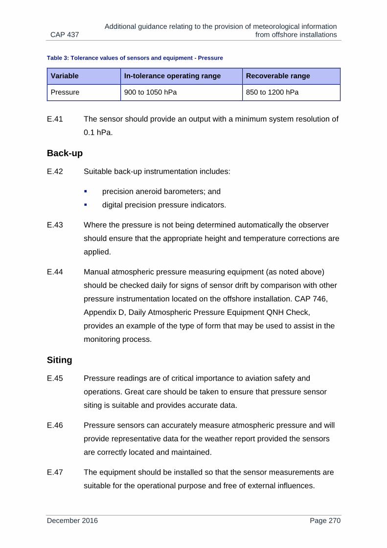
CAP 437 Additional guidance relating to the provision of meteorological information
from offshore installations
December 2016 Page 270
Table 3: Tolerance values of sensors and equipment - Pressure
Variable In-tolerance operating range Recoverable range
Pressure 900 to 1050 hPa 850 to 1200 hPa
E.41 The sensor should provide an output with a minimum system resolution of
0.1 hPa.
Back-up
E.42 Suitable back-up instrumentation includes:
precision aneroid barometers; and
digital precision pressure indicators.
E.43 Where the pressure is not being determined automatically the observer
should ensure that the appropriate height and temperature corrections are
applied.
E.44 Manual atmospheric pressure measuring equipment (as noted above)
should be checked daily for signs of sensor drift by comparison with other
pressure instrumentation located on the offshore installation. CAP 746,
Appendix D, Daily Atmospheric Pressure Equipment QNH Check,
provides an example of the type of form that may be used to assist in the
monitoring process.
Siting
E.45 Pressure readings are of critical importance to aviation safety and
operations. Great care should be taken to ensure that pressure sensor
siting is suitable and provides accurate data.
E.46 Pressure sensors can accurately measure atmospheric pressure and will
provide representative data for the weather report provided the sensors
are correctly located and maintained.
E.47 The equipment should be installed so that the sensor measurements are
suitable for the operational purpose and free of external influences.
CAP 437 Additional guidance relating to the provision of meteorological information
from offshore installations
December 2016 Page 271
E.48 If the equipment is not installed at the same level as the notified helideck
elevation, it should be given a correction factor in order to produce values
with respect to the reference point. For QNH this is the height above sea
level and for QFE the height of helideck above sea level.
E.49 Where required, the manufacturer's recommended venting method should
be employed to isolate the sensor from the internal environment. The
pressure sensor should be installed in a safe area, typically the
Telecommunications Room, and in close proximity to the Meteorological
processing system. In most cases, internal venting of the pressure
sensors will be satisfactory. However, if it is determined that internal
venting may affect the altimeter setting value to the extent that it is no
longer within the accuracy limits given below, outside venting should be
used. When the pressure sensor is vented to the outside a vent header
(water trap) should be used. The venting interface is designed to avoid
and dampen pressure variations and oscillations due to 'pumping' or
'breathing' of the pressure sensor venting equipment.
E.50 The sensors should also be located in an area free of jarring, vibration
and rapid temperature fluctuations (i.e. avoid locations exposed to direct
sunlight, draughts from open windows, and locations in the direct path of
air currents from heating or cooling systems). Regular inspections of the
vent header should be carried out to ensure that the header does not
become obstructed by dust etc.
Visibility
E.51 See CAP 746, Chapter 7.
Performance
E.52 The performance of the measuring system is limited by the range and field
of view of the sensor. The equipment should be capable of measurement
to the following accuracy limits to a range of 15 km:

CAP 437 Additional guidance relating to the provision of meteorological information
from offshore installations
December 2016 Page 272
Table 4: Performance of the visibility measuring system
Range Accuracy
Up to and including 550 m Visibility ±50 m
Between 600 m and 1,500 m Visibility ±10%
Between 1,5000 m and 15 km Visibility ±20%
E.53 The visibility measuring system should measure to a resolution of 50 m.
E.54 The sensor(s) should be sampled at a minimum rate of once per minute.
An averaging period of 10 minutes for weather reports should be used;
however, where a marked discontinuity occurs only those values after the
discontinuity should be used for obtaining mean values.
NOTE: A marked discontinuity occurs when there is an abrupt and sustained change in
visibility, lasting at least two minutes, which reaches or passes through the
following ranges:
10 km or more
5,000 m to 9 km
3,000 m to 4,900 m
2,000 m to 2,900 m
1,500 m to 1,900 m
800 m to 1,400 ,
740 m or less
Back-up
E.55 The accredited observer should assess the visibility by eye. Where
possible, visibility reference points should be provided. Structures
illuminated at night should be indicated. When the visibility has been
assessed by eye a remark should be included in the weather report form.

CAP 437 Additional guidance relating to the provision of meteorological information
from offshore installations
December 2016 Page 273
Siting
E.56 The sensor should be positioned in accordance with the manufacturer's
specifications and is normally mounted on a mast. The visibility sensor
transmits an infrared beam that measures the refraction caused by
suspended particles that obstruct visibility, i.e. mist, fog, haze, dust and
smoke. For this reason it is important to avoid any interference such as
flares, smoke vents, etc. Areas of the installation that are used for wash-
down or are susceptible to sea spray should be avoided. The sensor
should be located as far away as practicable from other light sources that
might affect the measurement, including direct sunlight or spotlights etc.,
as these will cause interference. These sensors are only suitable for safe
areas. These sensors require routine maintenance, calibration and
cleaning; hence they should be positioned in a location that is easily
accessible.
Present weather sensor
E.57 See CAP 746, Chapter 7.
Performance
E.58 The sensor should be capable of detecting a precipitation rate greater
than or equal to 0.05 mm per hour, within 10 minutes of the precipitation
commencing.
E.59 Where intensity is measured, the sensor should be capable of measuring
the range of intensity from 0.00 mm per hour to 100 mm per hour and
resolve this to the following resolutions:
Range Resolution
0 to 10 mm per hour 0.1 mm
10.5 to 50 mm per hour 0.5 mm
51 to 100 mm per hour 1.0 mm

CAP 437 Additional guidance relating to the provision of meteorological information
from offshore installations
December 2016 Page 274
E.60 The sensor should be accurate to within ±30% in the range 0.5 to 20 mm
per hour.
E.61 Where the sensor is capable of doing so, it should discriminate between
liquid precipitation and frozen precipitation.
Back-up
E.62 The accredited observer should assess the present weather manually,
assisted by reference material as appropriate. When the present weather
has been assessed manually a remark should be included in the offshore
weather report form.
Siting
E.63 The sensor should be positioned in accordance with the manufacturer's
specifications. The sensor should be located as far away as practicable
from the shielding effects of obstacles and structures.
Cloud
E.64 See CAP 746, Chapter 7.
Performance
E.65 The performance of the cloud base recorder is limited by the view of the
sensor. The equipment should be capable of measurement to the
following accuracy limits, from the surface up to 5,000 ft above ground
level:
Range Accuracy
Up to and including 300 ft Cloud height ±30 ft
Above 300 ft Cloud height ±10%
E.66 The cloud base recorder should measure to a resolution of 100 ft.
E.67 The sensor(s) should be sampled at a minimum rate of once per minute.

CAP 437 Additional guidance relating to the provision of meteorological information
from offshore installations
December 2016 Page 275
E.68 Where appropriate software is utilised, cloud base detection systems may
also provide an indication of the cloud amount. A cloud cover algorithm
unit calculates the cloud amounts and the heights of different cloud layers,
in order to construct an approximation of the entire sky. Such an
approximation is limited by the detection system's coverage of the sky and
should not be used in the weather report unless validated by the
accredited observer.
Back-up
E.69 The accredited observer should assess the cloud by eye and estimate the
height, assisted by reference material where appropriate. It should be
noted that human estimates of cloud height without reference to any form
of measuring equipment (particularly at night) may not meet the accuracy
requirements stated above, so it is essential that when the cloud height
has been assessed manually a remark is included in the offshore weather
report form.
Siting
E.70 The sensor should be positioned in accordance with the manufacturer's
specifications and is normally mounted on a platform or pedestal. The
sensor should be located as far away as practicable from other light
sources or reflections that might affect the measurement. Most
ceilometers are fitted with blowers that prevent precipitation from settling
on the lens; however, it is recommended that the sensor is installed in an
area free of sea spray and away from any areas that are used routinely for
wash-down. The sensor should have a clear view of the sky, uninterrupted
by cranes or other structures that may obscure the sensor’s view. The
height of the sensor above sea level should be noted to ensure that the
necessary correction is applied to all readings. These types of sensors are
only suitable for installation in safe areas and should not be installed near
to radars or other radio transmitters.

CAP 437 Additional guidance relating to the provision of meteorological information
from offshore installations
December 2016 Page 276
Calibration, maintenance and servicing periods
E.71 All primary and back-up sensors should be serviced by an engineer on at
least an annual basis. Calibration should take place according to the
instrument manufacturer's recommendation. Cleaning and routine
maintenance should take place according to the instrument
manufacturer's guidance; however, due to the harsh offshore
environment, cleaning routines may have to be increased in certain
conditions.
E.72 Unserviceable sensors should be repaired as soon as possible in order to
ensure that accurate, timely and complete meteorological observations
are provided in support of safe and efficient helicopter operations.

CAP 437 Procedure for authorising offshore helicopter landing areas – letter to
offshore helicopter operators, October 2011
December 2016 Page 277
Appendix F
Procedure for authorising offshore helicopter landing areas – letter to offshore helicopter operators, October 2011
Safety Regulation Group
Flight Ops Inspectorate (Helicopters)
October 2011
Dear Sirs
PROCEDURE FOR AUTHORISING OFFSHORE HELICOPTER LANDING AREAS
This letter updates the legal requirements and related industry procedure for the
authorisation of offshore helicopter landing areas on installations and vessels for the
worldwide use by helicopters registered in the United Kingdom.
Article 96 of the Air Navigation Order (ANO) 2009 requires a public transport
helicopter operator to reasonably satisfy himself that every place he intends to take
off or land is suitable for purpose.
A UK registered helicopter, therefore, shall not operate to an offshore helicopter
landing area unless the operator has satisfied itself that the helicopter landing area is
suitable for purpose and that it is properly described in the helicopter operator's
Operations Manual.
CAP 437 gives guidance on standards for the arrangements that the CAA expects
an operator to have in place in order to discharge this responsibility under article 96.
The Helideck Certification Agency (HCA) procedure is established through a
memorandum of understanding to withdraw helicopter landing area certification on
behalf of the four offshore helicopter operators - Bristow Helicopters Ltd, Bond
Offshore, CHC Scotia and British International Helicopters - to enable each to
discharge its responsibilities under the ANO.
CAP 437 Procedure for authorising offshore helicopter landing areas – letter to
offshore helicopter operators, October 2011
December 2016 Page 278
Article 12 of the ANO 2009 provides that to hold an Air Operator's Certificate (AOC)
an operator must satisfy the CAA that amongst other things its equipment,
organisation and other arrangements are such that it is able to secure the safe
operation of aircraft.
When looking at a particular operator, the CAA will therefore have regard to its ‘other
arrangements’. These arrangements include the manner in which the operator
discharges its duty under article 96, and the CAA for the grant or ongoing
assessment of an AOC will audit the helicopter operators’ application of the process
on which the operator relies. As part of such an audit the CAA will periodically audit
the processes and procedures of the HCA, in acting in the role of a sub-contractor to
the helicopter operators providing their services to AOC holders for the purpose of
authorising offshore helicopter landing areas. As part of such an audit, the CAA will
review the HCA procedures and processes and may accompany an operator when
the operator undertakes an audit of the HCA procedures or inspects an offshore
helicopter landing area.
The legal acceptance for the safety of landing sites rests with the helicopter operator.
Yours faithfully
Captain C Armstrong
Manager Flight Operations Inspectorate (Helicopters)

CAP 437 Guidance for helideck floodlighting systems
December 2016 Page 279
Appendix G
Guidance for helideck floodlighting systems
Introduction
G.1 Chapter 4 sets out the best practice requirements for helideck lighting
systems consisting of green perimeter lighting, a lit TD/PM Circle and a lit
heliport identification 'H' marking. The statement is made within this
paragraph that reliance on helideck floodlighting as a provision of primary
visual cueing is no longer supported. However, the CAA has no objection
to systems conforming to the good practice guidance contained in this
Appendix being retained as a back-up for the Circle and 'H' lighting.
Where required, floodlights may also be used for lighting the installation
name on the helideck.
G.2 In addition, floodlights may be used for the purpose of providing a source
of illumination for on-deck operations, such as refuelling and passenger
handling. Any floodlighting provided for on-deck operations should be
turned off for the approach, landing and take-off.
General considerations for helideck floodlighting
G.3 The whole of the landing area should be adequately illuminated if
intended for night use. Experience has shown that floodlighting systems,
even when properly aligned, can adversely affect the visual cueing
environment by reducing the conspicuity of helideck perimeter lights
during the approach, and by causing glare and loss of pilots' night vision
during the hover and landing. Furthermore, floodlighting systems often fail
to provide adequate illumination of the centre of the landing area leading
to the so called 'black-hole effect'. It is essential, therefore, that any
floodlighting arrangements take full account of these problems. Further
good practice guidance on suitable arrangements is provided (below) in

CAP 437 Guidance for helideck floodlighting systems
December 2016 Page 280
paragraph 3 'Improved Floodlighting System', extracted from a further
interim guidance letter issued by the CAA on 9 March 2006 and updated
for this Appendix.
G.4 Although the modified floodlighting schemes described will provide useful
illumination of the landing area without significantly affecting the
conspicuity of the perimeter lighting and will minimise glare, trials have
demonstrated that neither they nor any other floodlighting system is
capable of providing the quality of visual cueing available by illuminating
the TD/PM and 'H' (see Chapter 4, paragraph 4.22). These modified
floodlighting solutions should therefore be regarded as temporary
arrangements only. It is essential that any such floodlighting systems are
considered in collaboration with the helicopter operator who may wish to
fly a non-revenue approach to a helideck at night before confirming the
acceptability of the scheme.
G.5 The floodlighting should be arranged so as not to dazzle the pilot and, if
elevated and located off the landing area clear of the LOS, the system
should not present an obstacle to helicopters landing and taking off from
the helideck. All floodlights should be capable of being switched on and
off at the pilot's request. Setting up of lights should be undertaken with
care to ensure that the issues of adequate illumination and glare are
properly addressed and regularly checked. For some decks it may be
beneficial to improve depth perception by floodlighting the main structure
or 'legs' of the platform.
NOTE: It is important to confine the helideck lighting to the landing area, since any light
overspill may cause reflections from the sea. The floodlighting controls should be
accessible to, and controlled by, the HLO or Radio Operator.

CAP 437 Guidance for helideck floodlighting systems
December 2016 Page 281
Improved floodlighting system
A modified extract from the CAA’s letter to industry dated 9 March
2006
G.6 For helidecks located on platforms with a sufficiently high level of
illumination from cultural lighting, the need for an improved floodlighting
system may be reviewed with the helicopter operator(s), i.e. in such
circumstances it may be sufficient just to delete or disable the existing
deck level floodlighting. This concession assumes that the level of
illumination from cultural lighting is also sufficiently high to facilitate deck
operations such as movement of passengers and refuelling (where
applicable). It is a condition that, prior to the removal of floodlights,
extended trials of the 'no-floodlight' configuration are conducted and their
subsequent removal will be subject to satisfactory reports from air crews
to indicate the acceptability of operating to the helideck with the re-
configured lighting.
G.7 In the absence of sufficient cultural lighting, the CAA recommends that
installation owners consider a deck level floodlighting system consisting of
four deck-level xenon floodlights (or alternative lights having the same
photometric specification) equally spaced around the perimeter of the
helideck. In considering this solution, installation owners should ensure
that the deck-level xenon units do not present a source of glare or loss of
pilots' night vision on the helideck, and do not affect the ability of the pilots
to determine the location of the helideck on the installation. It is therefore
essential that all lights are maintained in correct alignment. It is also
desirable to position the lights such that no light is pointing directly away
from the prevailing wind. Floodlights located on the upwind (for the
prevailing wind direction) side of the deck should ideally be mounted so
that the centreline of the floodlight beam is at an angle of 45º to the
reciprocal of the prevailing wind direction. This will minimise any glare or
disruption to the pattern formed by the green perimeter lights for the

CAP 437 Guidance for helideck floodlighting systems
December 2016 Page 282
majority of approaches. An example of an acceptable floodlighting
arrangement is shown at Figure 1.
NOTE: For some larger helidecks it may be necessary to consider fitting more than four
deck-level xenon floodlights (or alternative lights having the same photometric
specification), but this should be carefully considered in conjunction with the
helicopter operator giving due regard to the issues of glare and loss of definition
of the helideck perimeter before further deck-level units are procured. The CAA
does not recommend more than six units even on the largest helidecks. The
height of any floodlighting when installed around the helideck should not exceed
25 cm above deck level or (for a helideck where the D-value is 16.00 m or less)
be more than 5 cm above deck level.
Figure 3: Typical floodlighting arrangement

CAP 437 Risk assessment for helicopter operations to helidecks in the UKCS which
are sub-1D
December 2016 Page 283
Appendix H
Risk assessment for helicopter operations to helidecks in the UKCS which are sub-1D
H.1 The following table should form the basis of an aeronautical study (risk
assessment) conducted by, or on behalf of, an offshore helicopter
operator when intending to service helidecks using helicopters with an
overall length (D) greater than the design D of the helideck (referred to in
this document as a sub-1D operation). The assumption is made that sub-
1D operations will only be considered in the following circumstances
and/or conditions:
1) Applicable only for multi-engine helicopters operating to performance
class 1 or class 1 equivalent, or to performance class 2 when taking
into account drop down and deck edge miss during the take-off and
landing phase.
2) For a helideck that provides a load bearing surface (represented by
the Touchdown and lift-off area - the TLOF) of between 0.83D and
1D, it should be ensured that a minimum 1D circle (representing the
Final approach and take-off area – the FATO) is assured for the
containment of the helicopter. From the periphery of the FATO (not
the TLOF) the LOS extends; the non load-bearing area between the
TLOF perimeter and the FATO perimeter should be entirely free of
‘non-permitted’ obstacles while ensuring that any objects essential
for the operation located on or around the TLOF (load bearing)
perimeter should not exceed the revised obstruction height criteria
set out in paragraph 5 below.
3) This assessment may be considered for any helideck on a fixed
offshore installation whether a PMI or NUI. An installation or vessel
that is subject to dynamic motions exceeding HCA stable deck
criteria in pitch, roll and heave, should not be considered for
alleviation from the CAP 437 1D Standard.

CAP 437 Risk assessment for helicopter operations to helidecks in the UKCS which
are sub-1D
December 2016 Page 284
4) This assessment when applied to helidecks completed on or before
1 January 2012, may take advantage of an ICAO alleviation
permitting the outboard edge of the (approximately) 1.5m helideck
perimeter netting to extend above the level of the landing area by no
more than 25 cm (i.e. no structural modification of deck edge netting
supports is mandated by Annex 14 where the 25 cm height limitation
is not exceeded for older installations). However, for installations
completed on or after 1 January 2012 it is expected that the 4th
Edition Annex 14 Volume II Standard (3.3.15) be met - this requires
that the height of the helideck safety net be no greater than the
adjacent helideck load-bearing surface.
5) For helidecks that are minimum size (0.83D), ICAO Annex 14
Volume II prescribes the height limit for permitted objects around the
edge of the TLOF, and in the 1st segment of the LOS, to be 5 cm.
For helidecks which are =>1D (and also have a D-value >16.00m) a
25 cm limitation is currently applied. This risk assessment is content
to permit for existing helidecks with a TLOF between the 0.83D
minimum and the 1D (standard) a rising scale for the treatment of
essential objects around of the TLOF perimeter and for the 1st
segment of the LOS. “Essential objects” permitted around the edge
of the TLOF are notified in CAP 437, Chapter 3, paragraph 3.23 and
include helideck guttering and raised kerb, helideck lighting, foam
monitors (or ring-main system) where provided and, helideck
perimeter netting for helidecks completed on or before 1 January
2012. For sub-1D operations the following limits may apply between
the TLOF and FATO boundary and in the LOS 1st segment: For a
TLOF: >0.83D = 5 cm ADL, >0.92D = 15 cm ADL, 1D> = not more
than 25 cm ADL. For helidecks completed after 14 November 2013
where the TLOF is 16.00m or less all essential objects around the
TLOF should be limited to 5 cm. Figure 1 illustrates a 0.83D
minimum size TLOF. The inner circle bounded by the octagonal-
shaped helideck represents the sub-1D TLOF (in the illustration a
0.83D load bearing surface). The outer circle illustrates the 1D FATO

CAP 437 Risk assessment for helicopter operations to helidecks in the UKCS which
are sub-1D
December 2016 Page 285
which provides containment of the helicopter and from which is
derived the origin of the LOS. The chevron denoting the origin
should be physically marked at the periphery of the FATO. The
diameter of the TLOF is the declared D, marked at the chevron.
6) Operations to sub-1D fixed helidecks should not be considered
below 0.83D. Operations to moving helidecks should not be
considered below 1D.
7) The size of the landing area should not be less than minimum
dimensions prescribed in the approved Rotorcraft Flight Manual
Supplement.
Table 5: Non-compliance with ICAO standards/considerations/mitigations to account for compromise
1 Potential for a
reduction in the
distance from
helideck (TLOF)
centre to the limited
obstacle sector (LOS)
(denoting the origin of
the 1st and 2nd
segments).
Annex 14 Volume II
(4th Edition), Section
4.2.16 and Figure 4-9
It is essential that clearance from obstacles in the LOS is
maintained; for this reason, the sub-1D load bearing (landing)
surface (the TLOF) should be surrounded by a 1D circle (the
FATO) that is (with the exception of permitted objects) free of
any obstacles. This will reflect the obstacle clearances
provided for a 1D helideck (but see also the provision of 6a).
To ensure that obstacle clearances are maintained for the
helicopter, the touchdown and positioning marking circle
should be 0.5 of the notional 1D FATO (not of the landing
surface (the TLOF)), and located at the centre of the TLOF;
and never offset (Annex 14, Volume II, 5.2.10.4 and CAP 437
Glossary of Terms for TD/PM circle refer). E.g.: For an AW
139 (a D=16.63m helicopter) operating to a 16.00m diameter
load bearing TLOF, the inner diameter of the TD/PM circle,
located on helideck (TLOF) centre, should be 16.63 x 0.5 =
8.315m. The FATO minimum diameter should be 16.63m.
2 Reduction in suitable
and sufficient visual
references required
for the pilot during all
flight phases.
Adequate visual cues provided for aircrew are essential for the
conduct of safe operations to helidecks. On a sub-1D helideck
it is likely these will to some extent be compromised. An
aeronautical study should ensure that visual cues, within their
field of view are adequate for aircrew to perform the following
visual tasks:

CAP 437 Risk assessment for helicopter operations to helidecks in the UKCS which
are sub-1D
December 2016 Page 286
ICAO Heliport
Manual, Chapter 5
Identification of helideck location early on in the
approach
Visual cues to help maintain the sight picture during
approach
Visual cues on final approach to hover position
Visual cues for landing
Visual references on lift-off and hover
It is important that the helideck visual cues (in the form of
effective markings and lighting) are in accordance with CAP
437, Chapter 4 and that markings and deck mounted lighting
remain uncontaminated at all times (e.g. deposits of guano on
the surface of a helideck may compromise markings and/or
deck-mounted lighting). A wind sock should be provided to
facilitate an accurate indication of wind direction and strength
over the helideck. For night operations lighting systems should
include effective obstruction lighting in addition to helideck
lighting (consisting of perimeter lights and “H” and circle
lighting) and an illuminated windsock.
3 Reduction in the
space available for
passengers and crew
to safely alight and
embark the helicopter
and to transit to and
from the operating
area safely.
ICAO Heliport
Manual, Section
2.3.1.3
The reduction in available load-bearing surface (area) means
that clearances between passengers/crew moving around the
helideck and the rotor systems of the helicopter are reduced. It
is essential that this is fully considered on a helicopter type
specific basis. It should be ensured that sufficient access
points are available to avoid the situation of passengers and
crew having to pass close to helicopter ‘no-go’ areas (e.g. in
relation to main and tail rotor systems). Where, to avoid these
issues, personnel are required to transit close to the deck
edge, an operating (wind) limit may need to be considered to
assure the safe movement of passengers. Additional lighting
may be required to ensure safe movements are maintained at
night.
4 Reduction in the
space available for
securing helicopters,
The surface area available should be able to comfortably
accommodate a sufficient tie-down pattern arrangement to
allow the most critical helicopter(s) to be tied-down (as

CAP 437 Risk assessment for helicopter operations to helidecks in the UKCS which
are sub-1D
December 2016 Page 287
for the conduct of safe
and efficient refuelling
operations (where
provided) and for
post-crash teams to
provide effective fire
and rescue
intervention in the
event of an incident or
accident occurring.
ICAO Heliport
Manual, Section
2.3.1.3 and Section
6.8.1
required). Where refuelling operations are conducted the
space available around the helicopter should allow this to
occur safely and efficiently at all times. Sufficient access
points should be provided to allow fire and rescue teams to
move to the scene of a helideck incident or accident from an
upwind location and to allow passengers to escape downwind
to safety.
5 Elements of the
helicopter will be over
permitted obstacles at
the edge of the load
bearing landing
surface.
ICAO Annex 14
Volume II, Section
3.3.4, 3.3.12 and
3.3.13
Commencing at the 3rd Edition of Annex 14 Volume II, the
permitted height for essential objects located around the TLOF
in the 210° obstacle free sector and in the 1st segment of the
150° limited obstacle sector reduced from 25 cm (10’) for a 1D
helideck to 5 cm (2’) for a TLOF which is less than 1D and/or
16.00m or less. For new builds this is regarded as adequate
mitigation for the reduction in the dimension of the load
bearing area to address the presence of objects which
because of their function are required to be located
immediately around the TLOF. For existing installations where
a TLOF is provided which is larger than the minimum (0.83D),
but <=1D, the maximum height of essential objects around the
perimeter may be relaxed [on an ascending scale] in
accordance with H.1 Condition 5.
6 Reduction in the
margin built-in to
allow for
touchdown/positioning
inaccuracies during
landing.
It should be assumed that even amongst experienced, well
trained aircrew there will inevitably be some degree of
variability in the actual point of touchdown within the landing
area. The touchdown/positioning marking circle provides an
effective visual reference to guide the handling pilot to the
point of touchdown (See CAP 437 Glossary of Terms,
including Note, for the TD/PM circle) but scatter has potential
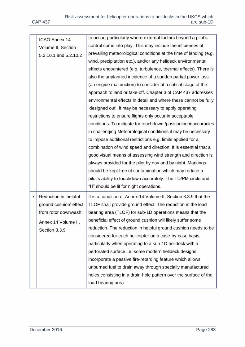
CAP 437 Risk assessment for helicopter operations to helidecks in the UKCS which
are sub-1D
December 2016 Page 288
ICAO Annex 14
Volume II, Section
5.2.10.1 and 5.2.10.2
to occur, particularly where external factors beyond a pilot’s
control come into play. This may include the influences of
prevailing meteorological conditions at the time of landing (e.g.
wind, precipitation etc.), and/or any helideck environmental
effects encountered (e.g. turbulence, thermal effects). There is
also the unplanned incidence of a sudden partial power loss
(an engine malfunction) to consider at a critical stage of the
approach to land or take-off. Chapter 3 of CAP 437 addresses
environmental effects in detail and where these cannot be fully
‘designed out’, it may be necessary to apply operating
restrictions to ensure flights only occur in acceptable
conditions. To mitigate for touchdown /positioning inaccuracies
in challenging Meteorological conditions it may be necessary
to impose additional restrictions e.g. limits applied for a
combination of wind speed and direction. It is essential that a
good visual means of assessing wind strength and direction is
always provided for the pilot by day and by night. Markings
should be kept free of contamination which may reduce a
pilot’s ability to touchdown accurately. The TD/PM circle and
“H” should be lit for night operations.
7 Reduction in ‘helpful
ground cushion’ effect
from rotor downwash.
Annex 14 Volume II,
Section 3.3.9
It is a condition of Annex 14 Volume II, Section 3.3.9 that the
TLOF shall provide ground effect. The reduction in the load
bearing area (TLOF) for sub-1D operations means that the
beneficial effect of ground cushion will likely suffer some
reduction. The reduction in helpful ground cushion needs to be
considered for each helicopter on a case-by-case basis,
particularly when operating to a sub-1D helideck with a
perforated surface i.e. some modern helideck designs
incorporate a passive fire-retarding feature which allows
unburned fuel to drain away through specially manufactured
holes consisting in a drain-hole pattern over the surface of the
load bearing area.

CAP 437 Risk assessment for helicopter operations to helidecks in the UKCS which
are sub-1D
December 2016 Page 289
Glossary of terms and abbreviations
FATO Final approach and take-off area – A defined area over which the final
phase of an approach manoeuvre to hover or landing is completed
and from which the take-off manoeuvre is commenced.
TLOF Touchdown and lift-off area – A dynamic load bearing area on which
a helicopter may touchdown and lift-off.
FATO/TLOF For helidecks of ≥ 1D, the FATO and TLOF are always coincidental
and therefore occupy the same space and have the same load
bearing characteristics. For helidecks which are < 1D, but no less
than 0.83D, it is the TLOF only that is permitted to reduce, the FATO
remains as 1D. In this case the TLOF and the FATO are assumed to
be collocated.
Essential objects
permitted
Includes, but may not be limited to a) around the TLOF: perimeter and
floodlights, guttering and raised kerb, foam monitors or ring main
system, handrails and associated signage, status lights, b) on the
TLOF: helideck net and helideck touchdown marking (“H” and “circle”)
lighting, c) in the area between the TLOF perimeter and the FATO
perimeter, helideck safety netting is present (for installations
completed on or before 1 January 2012 this is permitted to exceed
above the TLOF surface. For helidecks completed after 1 January
2012 the outboard edge of netting should be flush level with the load
bearing [landing] area).

CAP 437 Risk assessment for helicopter operations to helidecks in the UKCS which
are sub-1D
December 2016 Page 290
Figure 1: Obstacle limitation surface and sectors for a 0.83D TLOF

CAP 437 CAA protocol for operations against operating status lights or black decks
December 2016 Page 291
Appendix I
CAA protocol for operations against operating status lights or black decks
Platform: ......................................................................................................................
Name of offshore installation manager responsible: ....................................................
.....................................................................................................................................
Dispensation is requested to permit a Helicopter landing on subject platform’s
helideck, with NUI status lights flashing/non-functional. A Duty-Holder’s case-specific
risk assessment is attached to this dispensation request. Please provide as much
information as possible in column B.
Platform status is detailed below. Key permissive criteria are detailed on Page 2.
Installation status details
Helideck status
Column A Column B
1 Are or have the NUI status lights been
activated?
2 Are NUI status lights disabled or de-
powered?
3 Are NUI status lights reset and remain
functional?
4 Are helideck perimeter/circle lights
functional?
5 Are helideck floodlights functional?
6 Does the helideck have automated
fire-fighting?

CAP 437 CAA protocol for operations against operating status lights or black decks
December 2016 Page 292
7 Is the automated fire-fighting system
functional?
8 Is there anything else the pilot/operator
should be made aware of?
Installation status
9 Are comms live and showing
installation status?
10 Is the installation in ESD status/has the
system taken executive action?
11 Is the platform running under a normal
power supply?
12 Is the platform running under a UPS?
13 Have you been able to confirm the well
and pipeline valves confirmed shut?
14 Does the installation have automatic
venting/blowdown?
15 Have you been able to confirm the
blowdown valve(s) (if fitted) have
opened?
16 If so, have the topsides been vented
and confirmed diminished to an
expected and safe level?
17 Is power generation or back-up power
online?
18 Is the detected event ‘Gas’, ‘Fire’ or
‘Other’?
19 What was the initiating event?
Gas detection causal event (delete if not applicable)
20 Is detection of a confirmed or
unconfirmed nature?
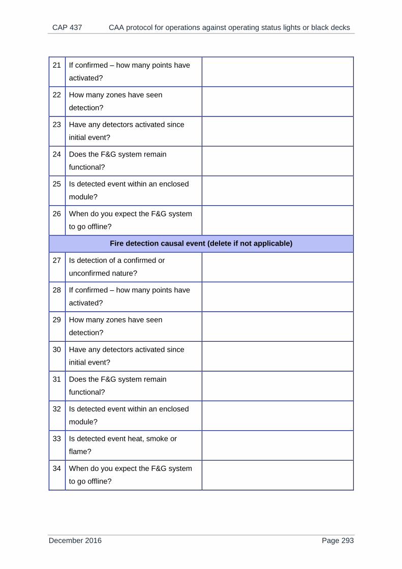
CAP 437 CAA protocol for operations against operating status lights or black decks
December 2016 Page 293
21 If confirmed – how many points have
activated?
22 How many zones have seen
detection?
23 Have any detectors activated since
initial event?
24 Does the F&G system remain
functional?
25 Is detected event within an enclosed
module?
26 When do you expect the F&G system
to go offline?
Fire detection causal event (delete if not applicable)
27 Is detection of a confirmed or
unconfirmed nature?
28 If confirmed – how many points have
activated?
29 How many zones have seen
detection?
30 Have any detectors activated since
initial event?
31 Does the F&G system remain
functional?
32 Is detected event within an enclosed
module?
33 Is detected event heat, smoke or
flame?
34 When do you expect the F&G system
to go offline?
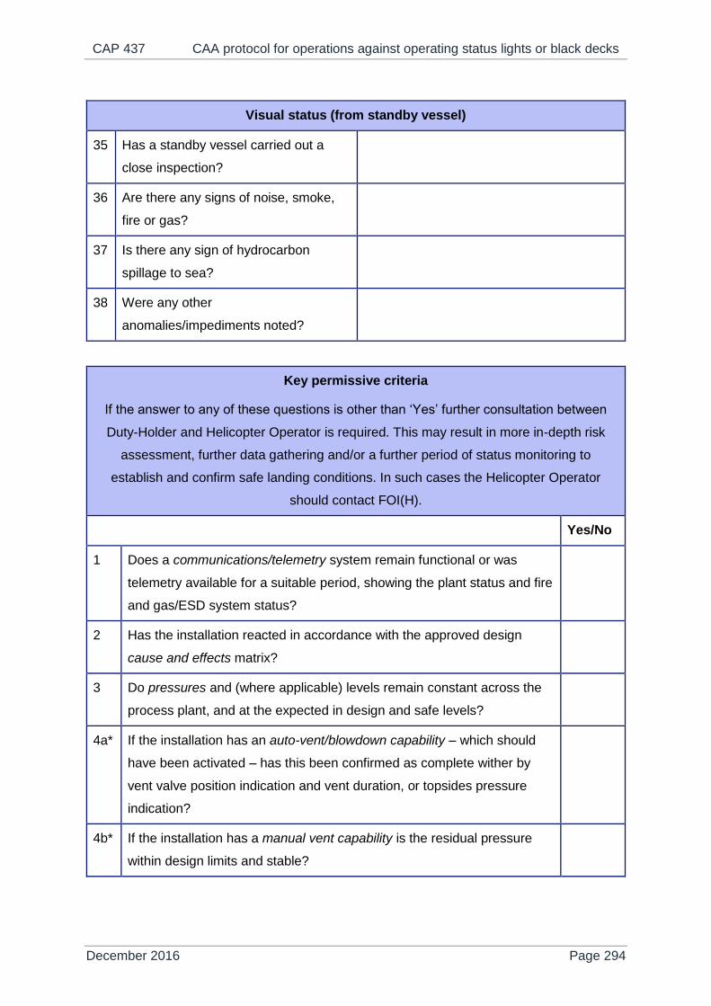
CAP 437 CAA protocol for operations against operating status lights or black decks
December 2016 Page 294
Visual status (from standby vessel)
35 Has a standby vessel carried out a
close inspection?
36 Are there any signs of noise, smoke,
fire or gas?
37 Is there any sign of hydrocarbon
spillage to sea?
38 Were any other
anomalies/impediments noted?
Key permissive criteria
If the answer to any of these questions is other than ‘Yes’ further consultation between
Duty-Holder and Helicopter Operator is required. This may result in more in-depth risk
assessment, further data gathering and/or a further period of status monitoring to
establish and confirm safe landing conditions. In such cases the Helicopter Operator
should contact FOI(H).
Yes/No
1 Does a communications/telemetry system remain functional or was
telemetry available for a suitable period, showing the plant status and fire
and gas/ESD system status?
2 Has the installation reacted in accordance with the approved design
cause and effects matrix?
3 Do pressures and (where applicable) levels remain constant across the
process plant, and at the expected in design and safe levels?
4a* If the installation has an auto-vent/blowdown capability – which should
have been activated – has this been confirmed as complete wither by
vent valve position indication and vent duration, or topsides pressure
indication?
4b* If the installation has a manual vent capability is the residual pressure
within design limits and stable?
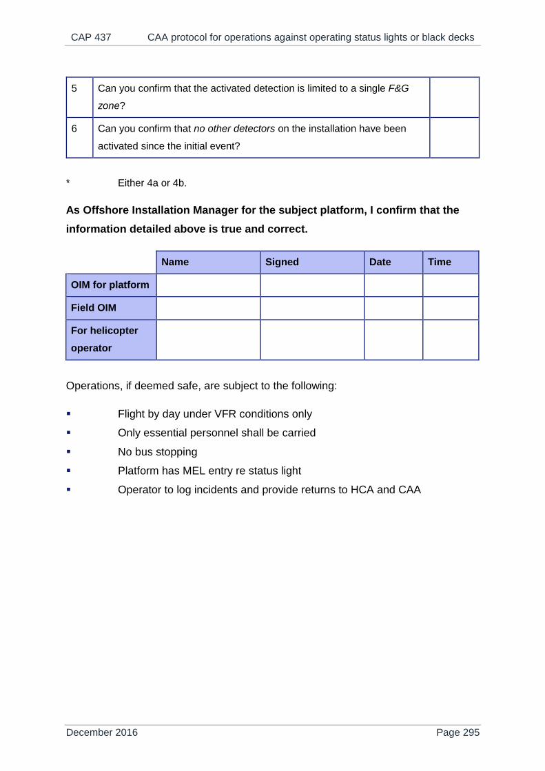
CAP 437 CAA protocol for operations against operating status lights or black decks
December 2016 Page 295
5 Can you confirm that the activated detection is limited to a single F&G
zone?
6 Can you confirm that no other detectors on the installation have been
activated since the initial event?
* Either 4a or 4b.
As Offshore Installation Manager for the subject platform, I confirm that the
information detailed above is true and correct.
Name Signed Date Time
OIM for platform
Field OIM
For helicopter
operator
Operations, if deemed safe, are subject to the following:
Flight by day under VFR conditions only
Only essential personnel shall be carried
No bus stopping
Platform has MEL entry re status light
Operator to log incidents and provide returns to HCA and CAA

CAP 437 Specification for a helicopter hoist status light
December 2016 Page 296
Appendix J
Specification for a helicopter hoist status light
Application
J.1 With reference to paragraph 10.30 in Chapter 10 of CAP 437 – Standards
for Offshore Helicopter Landing Areas, wind turbine platforms are required
to be provided with a means of indicating that the blades and nacelle are
safely secured prior to commencing helicopter hoist operations.
J.2 A single green light is recommended for this purpose which is capable of
displaying both a steady and flashing green signal. A steady green signal
is displayed to indicate to the pilot that the turbine blades and nacelle are
secure and it is safe to operate. A flashing green signal is displayed to
indicate that the turbine is in a state of preparation to accept hoist
operations or, when displayed during hoist operations, that parameters
are moving out of limits. When the light is extinguished this indicates that
it is not safe to conduct helicopter hoist operations.
Operational requirements
Location
J.3 The light should be located on the winching area platform of the wind
turbine such that it remains within the field of view of the pilot during the
approach to the wind turbine and throughout the winching operation, i.e.
the coverage should be 360 deg. in azimuth. (The preferred location of the
light is on top of the Safety Zone railing as shown in CAP 437, Chapter 10
and in Figure 3 below).
NOTE: Obscuration of the light when installed due to the wind turbine blades may be
ignored.

CAP 437 Specification for a helicopter hoist status light
December 2016 Page 297
Performance
J.4 The light should be conspicuous at a range of at least 500m and
detectable at a range of at least 700m in a meteorological visibility of 3km
in daylight (Et = 10-3.5) and, if required, at night (Et = 10-6.1).
J.5 The light should not present a source of glare or dazzle the pilot. The
critical case in this respect is when the helicopter is closest to the light
during the winching operation itself; at this point the lowest elevation of
the helicopter relative to the light is assumed to be 15 degrees, i.e. at
least 3m above the light and laterally displaced by no more than 10m.
Note that lights with small apertures (e.g. lights using LED sources) will
result in higher luminance and will be more likely to cause glare; care
should be taken in designing the light to avoid excessive luminance.
Day/Night operation
J.6 Winching operations are presently conducted in daylight (VMC)
conditions, but may be permitted to take place at night in the future. Light
intensities for both day time and night operations are therefore specified.
In the event that night time operations are being conducted, the light unit
intensity should be controlled by a photocell as operation of the light at the
daylight setting at night is very likely to dazzle the pilot. This photocell
needs to be shielded from direct sunlight in order to correctly measure
ambient light, particularly during sunset and sunrise when the sun is low in
the sky.
J.7 The light should transition from the daylight setting to the night time
setting when the ambient illuminance falls below 500 lux and should
switch before it reaches 50 lux. The light should transition from the night
time setting to the daylight setting when the ambient illuminance rises
above 50 lux and before it reaches 500 lux. The transition from one
setting to another should be accomplished smoothly (linear transition to
within ±10%) without any noticeable step changes.

CAP 437 Specification for a helicopter hoist status light
December 2016 Page 298
Characteristics
J.8 The following characteristics should apply for both steady burning and
flashing modes of the helicopter hoist status light. All intensities should be
measured in accordance with the test procedures for helideck status lights
contained in Appendix B of CAA Paper 2008/01. The modified-Allard
method (see Appendix C of CAA Paper 2008/01) should be used for
calculation of the effective intensity.
The effective intensity as a function of elevation should be as
detailed in Table 1 and illustrated in Figures 1 and 2.
The effective intensity specified in Table 1 should apply to all angles
of azimuth.
The colour of the helicopter hoist status light should be green as
defined in ICAO Annex 14 Vol.1 Appendix 1, para. 2.1.1(c), whose
chromaticity lies within the following boundaries:
Yellow boundary x = 0.360 – 0.080y
White boundary x = 0.650y
Blue boundary y = 0.390 – 0.171x
In flashing mode, the light should flash at a rate of 120 flashes per
minute (2 Hz), ±10%. The maximum duty cycle should be no greater
than 50%.
The system should be designed so that it fails safe, i.e. any failure in
the helicopter hoist status light system should result in the light being
extinguished.
The system and its constituent components should comply with all
regulations relevant to the installation.
The light should be tested by an independent test house. The optical
department of the test house should be accredited to ISO/IEC
17025.
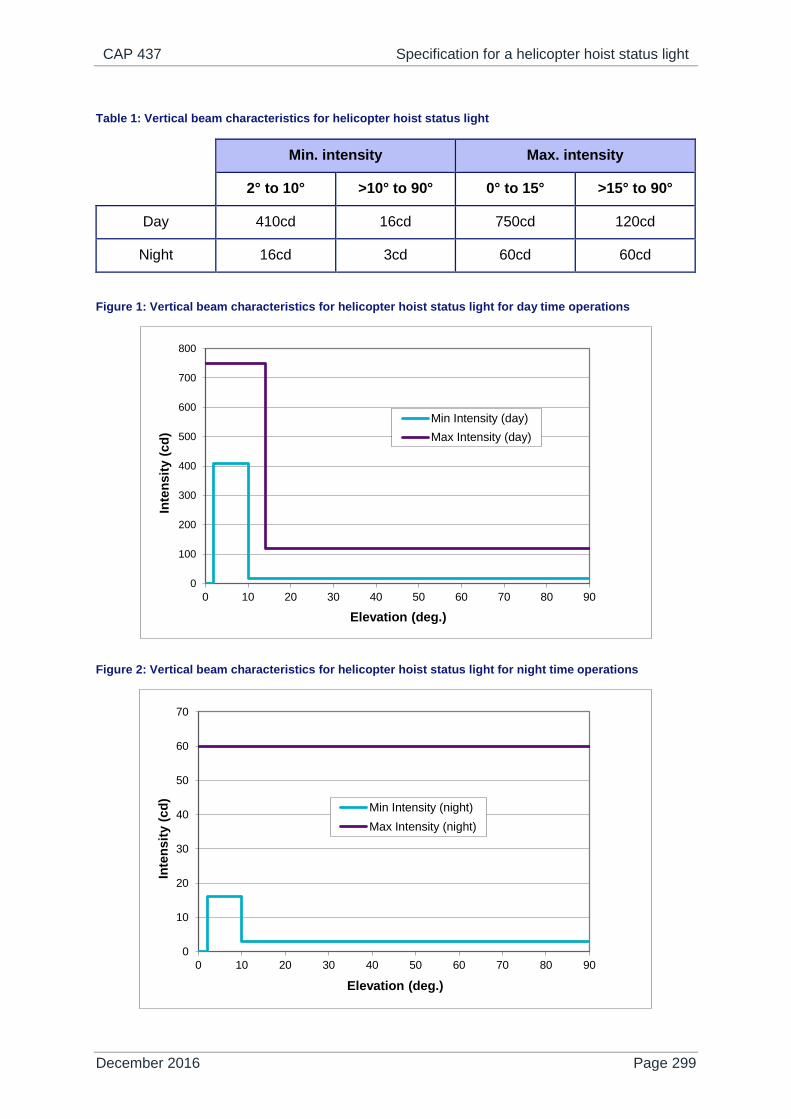
CAP 437 Specification for a helicopter hoist status light
December 2016 Page 299
Table 1: Vertical beam characteristics for helicopter hoist status light
Min. intensity Max. intensity
2° to 10° >10° to 90° 0° to 15° >15° to 90°
Day 410cd 16cd 750cd 120cd
Night 16cd 3cd 60cd 60cd
Figure 1: Vertical beam characteristics for helicopter hoist status light for day time operations
Figure 2: Vertical beam characteristics for helicopter hoist status light for night time operations
0
100
200
300
400
500
600
700
800
0 10 20 30 40 50 60 70 80 90
Inte
ns
ity (
cd
)
Elevation (deg.)
Min Intensity (day)
Max Intensity (day)
0
10
20
30
40
50
60
70
0 10 20 30 40 50 60 70 80 90
Inte
ns
ity (
cd
)
Elevation (deg.)
Min Intensity (night)
Max Intensity (night)

CAP 437 Specification for a helicopter hoist status light
December 2016 Page 300
Figure 3: Preferred location of the helicopter hoist status light (located on top of the safety railing)

CAP 437 Helideck friction survey protocol
December 2016 Page 301
Appendix K
Helideck friction survey protocol
Introduction
K.1 The protocol contained in this document represents a test method
acceptable to the CAA for the conduct of helideck friction surveys in
compliance with paragraph 3.39 of Chapter 3 of CAP 437, 8th edition,
Standards for Offshore Helicopter Landing Areas.
Friction measuring equipment
K.2 The exercise of measuring helideck friction involves a number of factors,
all of which have to be taken into consideration:
The limiting friction values cited in CAP 437 are related to the
threshold at which a helicopter would be expected to slide on a
helideck. The test method should therefore result in friction values
that are representative of the ‘real’ situation of a helicopter on a
helideck. For example, this suggests the use of a wheeled tester
employing a tyre made of the same material as helicopter tyres.
Within certain limits, a helicopter could land almost anywhere on a
helideck and an adequate level of friction should exist wherever the
helicopter wheels touchdown. This favours devices employing a
continuous measurement technique and surveys that cover the
entire surface of the helideck.
Human error and the influence of commercial pressure commonly
arise as factors in accidents, hence a measurement method that is
less reliant on human input would be expected to deliver greater
integrity. Devices that provide automatic electronic data collection,
storage and analysis are therefore to be preferred. In addition, this
also favours devices employing a continuous measurement
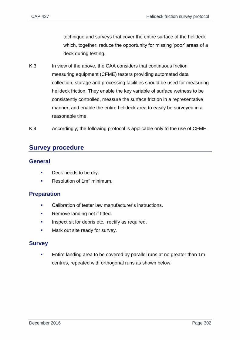
CAP 437 Helideck friction survey protocol
December 2016 Page 302
technique and surveys that cover the entire surface of the helideck
which, together, reduce the opportunity for missing ‘poor’ areas of a
deck during testing.
K.3 In view of the above, the CAA considers that continuous friction
measuring equipment (CFME) testers providing automated data
collection, storage and processing facilities should be used for measuring
helideck friction. They enable the key variable of surface wetness to be
consistently controlled, measure the surface friction in a representative
manner, and enable the entire helideck area to easily be surveyed in a
reasonable time.
K.4 Accordingly, the following protocol is applicable only to the use of CFME.
Survey procedure
General
Deck needs to be dry.
Resolution of 1m2 minimum.
Preparation
Calibration of tester iaw manufacturer’s instructions.
Remove landing net if fitted.
Inspect sit for debris etc., rectify as required.
Mark out site ready for survey.
Survey
Entire landing area to be covered by parallel runs at no greater than 1m
centres, repeated with orthogonal runs as shown below.

CAP 437 Helideck friction survey protocol
December 2016 Page 303
Figure 1: Helideck friction survey procedure using CFME testers
Presentation of results
For entire landing area, a matrix of readings for each 1 m square.
Average values for:
area inside TD/PM circle,
area outside TD/PM circle,
paint markings (where TD/PM circle and H lighting not installed).