aep and process bus
TRANSCRIPT

Abstract— American Electric Power (AEP) has defined
business goals, technical restraints and requirements for the
future installation of protection and control systems across the
entire AEP transmission network. The business goals are
focused on agile and cost effective deployment of Protection and
Control (P&C) systems that take advantage of IEC 61850 and
fiber optic technology. The technology shall meet the technical
performance of present day digital relays with conventional
practices while providing superior security and reliability in an
evolving NERC compliance environment. AEP has identified
“Process Bus”, or the concept of distributed I/O, as a key
technical element of standard protection systems to help meet
deployment goals. Process Bus, if implemented correctly, will
reduce field effort in wiring, testing, and commissioning without
sacrificing performance, reliability, and security of the system.
This paper will provide insight to the design criterion and
business objectives for a future protection and control system at
AEP.
1. INTRODUCTION
American Electric Power owns and operates, constructs and maintains, electric transmission infrastructure across eleven states within the continental U.S. Across this geographic footprint there is in excess of 1200 transmission and 2300 distribution substations. AEP transmission facilities operate in three different Regional Transmission Organizations (RTOs) that are responsible for coordinating operations of this infrastructure and the short-term reliability of the grid.
Figure 1-Regional Transmission Organizations
The reliability compliance for most of the North American
electric Grid is overseen by the North American Electric Reliability Corporation (NERC). NERC is subdivided into eight regional entities with AEP infrastructure existing in Reliability First Corporation (RFC), Southwest Power Pool (SPP), and Texas Reliability Corporation (TRE).
One reliability compliance standard that NERC enforces is the Critical Infrastructure Protection (CIP) requirements which are transitioning to Version 5 in 2016. The purpose of CIP is to address the physical and electronic security of cyber assets essential to the reliable operation of the electric grid. AEP, with more than 100 transmission facilities defined as critical under the incoming CIP Version 5, review CIP requirements very carefully and determine how they can impact engineering decisions for substation design.
Figure 2-NERC Regional Entities
Over the past two years, the AEP Transmission business has
grown substantially reaching an annual operating capital budget over $2 billion for new facilities and renovations to existing infrastructure. In fact, the capital budget has been trending upwards for the past five years when the $1 billion barrier was first passed for annual transmission projects. This is not unique to AEP Transmission, as many electric utility companies are seeing an increasing need for additional infrastructure and rehabilitation to an aging electrical grid. Protection and Control systems make up several pennies to the dollar of an overall transmission project, but these pennies add up to more than $100 million per year for AEP Transmission.
Protection and Control systems at AEP are designed and documented into “standards”, meaning these P&C systems are
AEP and Process Bus Balancing business goals and choosing the right technical solution
Jason M. Byerly, American Electric Power
highly developed for the predictable and reoccurring applications. Two examples of a standard relay package is a redundant line protection scheme consisting of two independent relays, designated as System 1 (Sys1) and System 2 (Sys2), and a separate breaker control/failure relay (Con1). The Sys1 and Sys2 protection systems are designed using different relay vendors to mitigate common failure modes.
Figure 3-Line protection (Sys1, Sys2) and breaker control/failure
(Con1)
One aspect of AEP standards that is essential to the efficient
execution of station projects and ongoing maintenance activities is the long life-cycle between replacements. It is not uncommon for standard relay applications to remain relatively unchanged for 8-10 years before revisions are considered to these protection packages. This approach in design philosophy increases repetition and therefore reduces training and documentation. The standards AEP uses provide many business and technical benefits, but one challenge is the ever-increasing field labor associated with copper wiring and wire terminations related to the integration of protection and control systems. To illustrate the labor requirements, a standard 345kV breaker and half line relay package with independent breaker control/failure protection will require 12 copper cables and more than 100 wire terminations between the substation yard equipment and relay systems in the control house.
The convergence of microprocessor relays and communications has brought about highly standardized communication frameworks such as IEC 61850. Utilities such as AEP appreciate the benefits of the IEC 61850 standards but cautiously approach change due to various business reasons such as training, change control, evolving industry regulations/standards, and technical evaluation. AEP is currently executing a plan to utilize IEC 61580 – Process Bus to reduce the time needed to construct, install, and commission protection and control systems. This paper will focus on the substation-yard environment and provide AEP’s viewpoint on the Process Bus solution that best fits our business and technical needs.
2. PROCESS BUS
The IEC 61850 9-2 standard pertains to a communication architecture between electronic devices located at the primary equipment in the substation yard and the protective relays located within the substation control house. The electronic device located at the primary equipment shall be named the Process Interface Unit (PIU) for purposes of this paper because it provides the interface to the primary equipment at the process level.
Figure 4-Process Interface Unit (PIU) design
Process Bus Data consists of two types of data: Sampled
Values (SV) and Generic Object Oriented Substation Event (GOOSE). The PIU will convert electrical measurements taken from traditional current and voltage transformers into a digital format called a Sampled Value. The PIU also supports contact inputs and outputs and digitizes data transmission to and from substation relays for the status and control of these inputs and outputs in the form of GOOSE messages.
With traditional copper wiring, a breaker and half line relay package and breaker control/failure protection requires 12 copper cables and more than 100 wire terminations, as previously stated. These numbers do not include panel wiring for routing of sources and controls from line protection to the breaker controls.
Purpose Cable Type Cable Qty Term. Qty
CT 4/C 4 32
VT 7/C 1 8
VT 7/C 1 8
Total 4 48
Table 1-Copper wiring for line relay (Sys1, Sys2)

Purpose Cable Type Cable Qty Term. Qty
Control 12/C 2 48
Control 7/C 2 16
CT 4/C 2 16
VT 4/C 2 16
Total 8 96
Table 2-Copper wiring for circuit breaker control/failure for two
breakers (Con1, Con2)
A Process Bus solution to this protection and control package requires 14 cables (4 copper, 10 fiber) with 28 fiber connections and 32 copper connections. The copper connections are for routing redundant DC power to the breaker mechanisms and PIU power supplies.
Purpose Cable Type Cable Qty Term. Qty
Control 1/F 4 8
VT 1/F 2 4
Total 6 12
Table 3-Fiber wiring for line relays (Sys1, Sys2)
Purpose Cable Type Cable Qty Term. Qty
Control 1/F 2 4
DC 4/C 4 32
VT 1/F 2 4
Total 8 40
Table 4-Fiber wiring for circuit breaker control/failure for two
breakers (Con1, Con2)
AEP has a large interest in this technology because we fully expect to see project cost reduction due to efficiencies gained in design, installation and ownership through the lifecycle of the equipment once we standardize the process bus application. The PIU will become the standard interface at the primary equipment and all field wiring will be reduced to fiber optic cables between the PIUs and protective relays. This will vastly reduce intensive field labor work by moving the wire terminations to the factory panel shops and equipment manufacturers.
The reduction in labor and commissioning cost is expected with any Process Bus technology but this alone cannot justify a migration to this technology. Protection and control engineers must consider all aspects of adopting Process Bus, from how it impacts field design and future maintenance to how the protective relay systems actually perform. Most importantly, protection and control systems are vital components to the power system and they must be available, reliable, and responsive to system abnormalities. Protection and control engineers need to understand the limits of performance before they can adopt a Process Bus System.
2.1. Competing Concepts
With the introduction of any new technology there is often competition among different design implementations that vie for market acceptance; ultimately the consumers determine the direction the technology takes. Process Bus in the North American market is still in an early adoption stage and many utility companies are exploring different architectures and
implementation concepts to see what best fits within their business model.
When it comes to choosing the best approach for implementing Process Bus within substations, the utility industry currently has two options. These options address the same problem and are not necessarily different in the data and function they perform; but are different more so in the engineering design approach they require. The difference in these two options is how they provide communications between PIUs and relays. One option uses an Ethernet switched network, and the other uses a direct point-to-point connection between PIUs and relays. AEP has evaluated both options and will discuss each approach below.
2.2. Switched Network
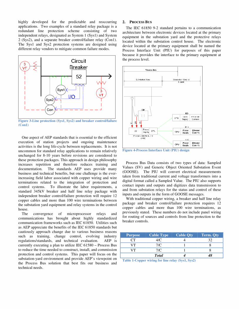
One design approach to a Process Bus implementation is referred to as the Switched Network (SN) Model. As the name implies, the PIU’s and the IED’s communicate over the Local Area Network (LAN) using Ethernet switches. The PIU datasets are published and multicast onto the LAN allowing any IED on the network the ability to subscribe to the datasets which are typically used for measurement and control purposes. To demonstrate the SN Process Bus concept, let’s return to the breaker and half example previously mentioned, and demonstrate how this may be implemented for line protection.
Figure 5 depicts a breaker and half – line zone example by applying relays from two different manufacturers. The blue color scheme applied to the PIU’s and IED signify one manufacturer and the green color signifies a second manufacturer. The two different relay manufacturers for the system #1 and #2 line protection is again an AEP requirement to prevent common mode of failure in the protection systems.
Each of the relay systems (PIU’s and IED’s) are connected to independent and redundant LAN’s with redundant GPS clocks. The Ethernet LAN is shown as a simplified box where in fact the LAN architecture may consist of multiple switches in various topologies.
The Process Bus datasets are published by the PIUs and multicast onto the LAN to allow the client (IED) the ability to subscribe to them for purposes of measurement acquisition and control functionality. Datasets from the various PIU’s area time aligned by a common external GPS clock source to account for network delays and data misalignment in the IED.
The design of a PIU using the SN Process Bus approach is not significantly different than the design of today’s protection and control IED. From a physical hardware standpoint, the SN PIU may include contact inputs and outputs for measurements and control as well as analog inputs for system measurements from traditional CT’s and VT’s.
The PIUs will be treated much like the relay in the substation control house from a programming standpoint. Each PIU will require configuration to subscribe to GOOSE datasets from the relays. They would also require configuration of SV datasets and the GOOSE datasets to be published. In addition to the aforementioned programming, the clock source identity and network addressing will need to be assigned and is now a critical component to the protection system.
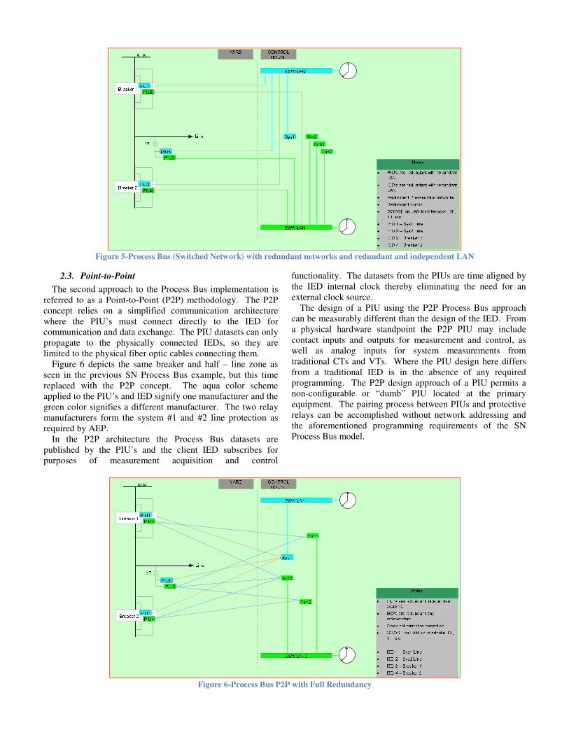
Figure 5-Process Bus (Switched Network) with redundant networks and redundant and independent LAN
2.3. Point-to-Point
The second approach to the Process Bus implementation is referred to as a Point-to-Point (P2P) methodology. The P2P concept relies on a simplified communication architecture where the PIU’s must connect directly to the IED for communication and data exchange. The PIU datasets can only propagate to the physically connected IEDs, so they are limited to the physical fiber optic cables connecting them.
Figure 6 depicts the same breaker and half – line zone as seen in the previous SN Process Bus example, but this time replaced with the P2P concept. The aqua color scheme applied to the PIU’s and IED signify one manufacturer and the green color signifies a different manufacturer. The two relay manufacturers form the system #1 and #2 line protection as required by AEP.
In the P2P architecture the Process Bus datasets are published by the PIU’s and the client IED subscribes for purposes of measurement acquisition and control
functionality. The datasets from the PIUs are time aligned by the IED internal clock thereby eliminating the need for an external clock source.
The design of a PIU using the P2P Process Bus approach can be measurably different than the design of the IED. From a physical hardware standpoint the P2P PIU may include contact inputs and outputs for measurement and control, as well as analog inputs for system measurements from traditional CTs and VTs. Where the PIU design here differs from a traditional IED is in the absence of any required programming. The P2P design approach of a PIU permits a non-configurable or “dumb” PIU located at the primary equipment. The pairing process between PIUs and protective relays can be accomplished without network addressing and the aforementioned programming requirements of the SN Process Bus model.
Figure 6-Process Bus P2P with Full Redundancy

3. PERSPECTIVE ON METHODOLOGY
In moving forward with an assessment for a best approach to accomplish Process Bus, it is important to remain focused on the goals of implementing this technology. It is every utility’s desire to find a technology that will save time and money during the overall life cycle of the equipment. While this is a worthy goal, if the reliability and performance of the protection and control assets are compromised by this new technology, it simply won’t be accepted.
Equally important considerations for a Process Bus technology are the security and simplicity of the overall design. Substation IED’s are not merely protective relays anymore, which in and of itself is critical; but IED’s facilitate automation, metering, annunciation, SCADA and controls the real-time management of the electrical system.
3.1. Performance
The primary requirement for any Process Bus protection system is simple: it must meet or exceed the performance and reliability of today’s hard wired copper protection and control systems. Process Bus must detect abnormal system conditions and operate to clear the faults fast enough to meet stability and safety requirements of the system. The protection and control equipment must be available to perform this primary task every time, all the time, 24/7.
3.1.1. Availability and Reliability
The protection and control system must work every time a fault occurs and the implementation of a Process Bus system will be different than traditional hard wired cable systems. What is needed for a Process Bus system to match that of a copper protection and control system is adequate redundancy and minimization of failure modes.
The P2P methodology relies on a communication architecture that does not involve any intermediary equipment like the Ethernet switch or GPS clock. The equipment used to build both P2P and SN PIUs is similar in hardware, which one can infer a similar Mean Time to Failure (MTTF) of this equipment. The major difference between a P2P and SN system that impacts availability and reliability is what occurs between the PIUs and IEDs.
Ethernet switches facilitate the transmission and reception of datasets between devices in a SN system and these datasets are time-aligned using distributed GPS clock sources. In contrast, a P2P system only requires physical connectivity using fiber optic cabling. The MTTF for the P2P system will therefore be improved over a reasonably designed SN Process Bus approach [1].
It is important to note that a P2P scheme will not eliminate the requirement for LAN equipment or redundancy protocols like Parallel Redundancy Protocol (PRP). These components will be used for redundant GOOSE message communication within the substation control house. The GOOSE implementation will replace traditional copper wiring for control interlocks, breaker failure initiates, and so forth.
3.1.2. Speed of System
Process Bus will introduce some time delay due to the use of fiber communications, sampled values, and GOOSE messaging between systems. To implement Process Bus, the speed of operation shall not adversely impact the protection and control systems and this is a primary goal of both approaches from the beginning.
There does not appear to be a clear advantage for either Process Bus approach over the other in regards to operating speed of the protection system. AEP has tested a P2P system approach and did validate and benchmark performance alongside a traditional copper wired P&C system. This evaluation is reviewed in section 5.
3.1.3. Repeatability and Determinism
The expectation is that protective relays and associated equipment will operate in the same fashion with the same operating times to achieve the intended results. Process Bus protective relay systems must match this repeatability of performance. Again, there seems to be no advantage for either Process Bus implementation approach.
The performance requirements are identical for the switched
network process bus and the point-to-point process bus methodologies. The characteristic that separates these two methods is availability and reliability of the P2P approach because they are not reliant on switched Ethernet connectivity and distributed time synchronization.
3.2. Security
The utilities in today’s business environment work with greater scrutiny from government and regulating entities than in previous years. The regulations imposed on the utilities often steer process and decisions on technologies such as Process Bus. One such regulation that has utilities devoting significant resources is the NERC Critical Infrastructure Protection (CIP) standards. The CIP standards have a deep impact on many business units at AEP, including substation design.
Several of the CIP requirements are related to cyber security. Their target is to protect the critical cyber infrastructure that may be vulnerable to a malicious attack from beyond the substation fence. The CIP requirements define what the critical substations of the electrical grid are, and the critical cyber assets and devices that are essential to the reliable operation of that substation. Cyber assets are also known as Programmable Electronic Devices (PED) which is widely considered any device with a microprocessor and field-updatable firmware, software or logic. AEP and other electrical utilities will have some variation on what details determine if a PED is a critical cyber asset but when a class of devices is deemed critical the CIP requirements are enforceable.
NERC CIP version 5 (CIP-5) will be implemented on April 1, 2016 and there are sections in these requirements that utilities should pay close attention to when choosing how to

best approach Process Bus. In the new requirements there is an important distinction made for critical cyber assets that are using externally routable connectivity and those that are not externally routable.
One section that highlights differences in requirements for routable versus non-routable cyber assets is the physical security of BES cyber systems [2]. Requirement R1 is basically mandating utilities to have a plan for physical security of critical cyber assets and reads as follows:
Each Responsible Entity shall implement, in a manner
that identifies, assesses, and corrects deficiencies, one or
more documented physical security plans that collectively
include all of the applicable requirement parts in CIP-
006-5 Table R1 –Physical Security Plan. [Violation Risk
Factor: Medium] [Time Horizon: Long Term Planning
and Same Day Operations].
Table R1 (Table 5, below) provides nine different requirements for protecting and monitoring critical cyber assets and only one of the nine requirements pertains to critical cyber assets without routable connectivity. To contrast, eight of the nine requirements apply to critical cyber assets with external routable connectivity. NERC CIP does not exclude PIUs implemented without external routable connectivity but the number of imposed requirements is far less and potentially easier to implement.
CIP-5 once again uses the external routable connectivity distinction in CIP-007-5 which deals with electronic security of the critical cyber assets. Devices without external routable connectivity are not specifically discussed in the electronics security sections of CIP-007-5 but devices with external routable connectivity will be subject to:
• Enable ports and services that are necessary and disabling all unnecessary ones (CIP-007-5 R1)
• Monitoring and alarming for failed logged activity and malicious code (CIP-007-5 R4)
• Enforce authentication of user access (CIP-007-5 R5)
• Management of shared access accounts (CIP-007-5 R5)
• Manage passwords for devices every 15 calendar months (CIP-007-5-R5)
These CIP requirements referenced and the others not
discussed mandate physical and electronic security is placed around all critical cyber assets. The level of security and management significantly changes for the class of devices without external routable connectivity to the class with external routable connectivity. It is recognized that a Process Bus system can be implemented with either P2P or SN topology, but it is also evident that a P2P system would be less problematic to apply into CIP substations.
AEP utilizes the substation control house as the physical security perimeter (PSP) and electronic security perimeter (ESP) for critical cyber assets. These critical cyber assets, under AEP design standards, do not leave the confines of the PSP and all routable connectivity of these critical cyber assets is prohibited from leaving the ESP. The concept of PSP and ESP is a complicating factor for adopting Process Bus, as the PIUs will be located with the primary equipment in the switchyard and a communication network of some type will be installed between PIUs and the control house.
The P2P Process Bus methodology adheres to the security constraints that AEP has placed on substation design because with this approach the PIU datasets communicate directly to the devices that need information without routable connection. This puts some bounds on cyber security risk without limiting the functional capabilities and requirements for a protection and control systems. Furthermore, it will reduce the number of requirements to implement into CIP substation and facilitate adoption more rapidly.
CIP-006-5 Table R1- Physical Security Plan
Part Applicable Systems Requirements Measures
1.1 Medium Impact BES Cyber Systems without External Routable
Connectivity Physical Access Control Systems (PACS) associated with: • High Impact BES Cyber Systems, or • Medium Impact BES Cyber Systems with External Routable
Connectivity
Define operational or procedural controls to restrict physical access.
An example of evidence may include, but is not limited to, documentation that operational or procedural controls exist.

1.2 Medium Impact BES Cyber Systems with External Routable Connectivity and their associated: 1. EACMS; and 2. PCA
Utilize at least one physical access control to allow unescorted physical access into each applicable Physical Security Perimeter to only those individuals who have authorized unescorted physical access.
An example of evidence may include, but is not limited to, language in the physical security plan that describes each Physical Security Perimeter and how unescorted physical access is controlled by one or more different methods and proof that unescorted physical access is restricted to only authorized individuals, such as a list of authorized individuals accompanied by access logs.
1.4 High Impact BES Cyber Systems and their associated: 1. EACMS; and 2. PCA Medium Impact BES Cyber Systems with External Routable Connectivity and their associated: 1. EACMS; and 2. PCA
Monitor for unauthorized access through a physical access point into a Physical Security Perimeter.
An example of evidence may include, but is not limited to, documentation of controls that monitor for unauthorized access through a physical access point into a Physical Security Perimeter.
1.5 High Impact BES Cyber Systems and their associated: 1. EACMS; and 2. PCA Medium Impact BES Cyber Systems with External Routable Connectivity and their associated: 1. EACMS; and 2. PCA
Issue an alarm or alert in response to detected unauthorized access through a physical access point into a Physical Security Perimeter to the personnel identified in the BES Cyber Security Incident response plan within 15minutes of detection.
An example of evidence may include, but is not limited to, language in the physical security plan that describes the issuance of an alarm or alert in response to unauthorized access through a physical access control into a Physical Security Perimeter and additional evidence that the alarm or alert was issued and communicated as identified in the BES Cyber Security Incident Response Plan, such as manual or electronic alarm or alert logs, cell phone or pager logs, or other evidence that documents that the alarm or alert was generated and communicated.
1.6 Physical Access Control Systems (PACS) associated with: • High Impact BES Cyber Systems, or • Medium Impact BES Cyber Systems with External Routable
Connectivity
Monitor each Physical Access Control System for unauthorized physical access to a Physical Access Control System.
An example of evidence may include, but is not limited to, documentation of controls that monitor for unauthorized physical access to a PACS.
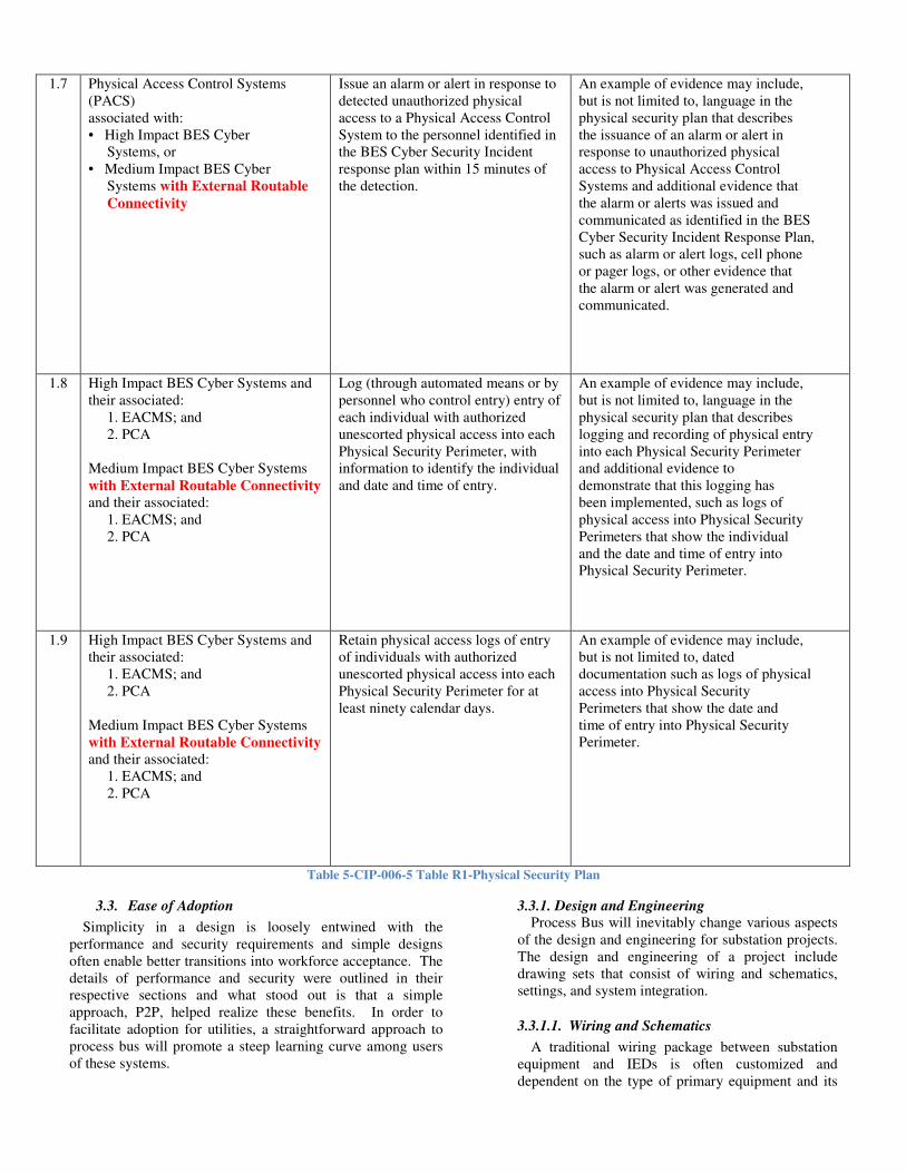
1.7 Physical Access Control Systems (PACS) associated with: • High Impact BES Cyber Systems, or • Medium Impact BES Cyber Systems with External Routable
Connectivity
Issue an alarm or alert in response to detected unauthorized physical access to a Physical Access Control System to the personnel identified in the BES Cyber Security Incident response plan within 15 minutes of the detection.
An example of evidence may include, but is not limited to, language in the physical security plan that describes the issuance of an alarm or alert in response to unauthorized physical access to Physical Access Control Systems and additional evidence that the alarm or alerts was issued and communicated as identified in the BES Cyber Security Incident Response Plan, such as alarm or alert logs, cell phone or pager logs, or other evidence that the alarm or alert was generated and communicated.
1.8 High Impact BES Cyber Systems and their associated: 1. EACMS; and 2. PCA Medium Impact BES Cyber Systems with External Routable Connectivity and their associated: 1. EACMS; and 2. PCA
Log (through automated means or by personnel who control entry) entry of each individual with authorized unescorted physical access into each Physical Security Perimeter, with information to identify the individual and date and time of entry.
An example of evidence may include, but is not limited to, language in the physical security plan that describes logging and recording of physical entry into each Physical Security Perimeter and additional evidence to demonstrate that this logging has been implemented, such as logs of physical access into Physical Security Perimeters that show the individual and the date and time of entry into Physical Security Perimeter.
1.9 High Impact BES Cyber Systems and their associated: 1. EACMS; and 2. PCA Medium Impact BES Cyber Systems with External Routable Connectivity and their associated: 1. EACMS; and 2. PCA
Retain physical access logs of entry of individuals with authorized unescorted physical access into each Physical Security Perimeter for at least ninety calendar days.
An example of evidence may include, but is not limited to, dated documentation such as logs of physical access into Physical Security Perimeters that show the date and time of entry into Physical Security Perimeter.
Table 5-CIP-006-5 Table R1-Physical Security Plan
3.3. Ease of Adoption
Simplicity in a design is loosely entwined with the performance and security requirements and simple designs often enable better transitions into workforce acceptance. The details of performance and security were outlined in their respective sections and what stood out is that a simple approach, P2P, helped realize these benefits. In order to facilitate adoption for utilities, a straightforward approach to process bus will promote a steep learning curve among users of these systems.
3.3.1. Design and Engineering
Process Bus will inevitably change various aspects of the design and engineering for substation projects. The design and engineering of a project include drawing sets that consist of wiring and schematics, settings, and system integration.
3.3.1.1. Wiring and Schematics
A traditional wiring package between substation equipment and IEDs is often customized and dependent on the type of primary equipment and its

layout. These variations in equipment wiring make this design step problematic due to time consumption. Adoption of Process Bus will simplify the wiring steps by standardizing how equipment is wired into PIUs and transition onsite field wiring work to equipment manufactures using lower cost factory labor.
The wiring stage will be simplified by choosing either process bus approach and will generally consist of running a fiber optic wire from the PIU to someplace inside the control house. For SN all fibers will terminate into Ethernet switches by separating
redundant systems to redundant LANs. For P2P the fiber optics will terminate into protection relays in much the same way as traditional copper wiring is done today but reducing the number of connections significantly.
The schematics of the protection systems will most likely transform into logic diagrams that will be used to document trips, lockouts, closes, interlocks, and so forth. There are various methods to document these details and that can vary depending on the engineer but either P2P or SN will see similar changes.
Figure 7-Fiber wiring comparison
3.3.1.2. Relay Settings and Integration
The settings required for both SN and P2P Process Bus may be very similar in process but this is not a requirement. The simplicity in design of a P2P system provides opportunity to simplify the process. For instance, the P2P does not require Ethernet connectivity and GPS time source assignments so the settings and integration can be reduced to simple commissioning steps or possibly eliminated.
Elimination of settings of the PIUs will have many benefits such as reduction of workload for engineers and commissioning, reduction in error, and a device without routable connectivity from a cyber-security standpoint.
It is AEP’s perspective that a PIU should be designed in a way that will eliminate programming, settings, updatable firmware, and is plug-in-play with protection relays. These design criteria will marry the benefits gained by implementing Process Bus without over-engineering a solution that is complicated, has a steep learning curve, and is difficult to achieve NERC CIP compliance.
3.3.2. Construction and Maintenance
Wiring, wire verification, and testing consumes much of the time during construction from a protection and control systems standpoint. As described earlier, process bus minimizes wiring and simplifies it to fiber optic terminations between PIUs and either Ethernet switches or relays.

Depending on how Process Bus is implemented the amount of time during commissioning may differ, therefore influencing a decision which to adopt. A simple design for the PIU that is strictly plug-and-play will tend to offer the least amount of change for individuals responsible for commissioning and testing. A PIU that is implemented as plug-and-play -without settings, will tend to act as a simple extension of a traditional relay backplane by moving the terminal blocks out into the switchyard.
For ease of adoption, the learning curve for Process Bus
implementation should be as flat as possible. One reason for this is the training cost associated with new technology and the standards development efforts in a large company like AEP are immense. A process bus approach that is similar to a copper-based solution will help the quick adoption during the transition because the engineering and design approach will be similar in nature.
4. PERSPECTIVE ON METHODOLOGY
In December of 2012, AEP and GE completed the installation of a distribution project at Roberts Road substation in Columbus, Ohio. This project was a pilot to monitor only the performance of the P2P method and validate against real system conditions. This project further demonstrated a brownfield installation and the efficiencies gained by installing a Process Bus system.
The Roberts Road project included eight distribution feeder circuit breakers, two 13.2kV distribution bus zones, and two 138/13.2kV distribution transformers. The P2P system was non-tripping of the primary equipment but fully monitored the performance against that of traditional hard-wired copper systems. Figure 8 provides a simplified one-line for the transformer (XF-4) and one bus bay of four distribution feeders (CB’s 11-14) at the substation.
Figure 8-Transformer #4 and Bus C Process Bus system
4.1. Process Bus Experience
With a pilot of the P2P system at a distribution voltage level, the frequency and quantity of system disturbances has provided many events to validate and benchmark its performance against the performance of the traditional copper systems. The P2P system was not wired to trip the primary equipment but to control a breaker simulator designed from auxiliary relays to provide an assessment of the system performance.
Numerous system events have been analyzed and benchmarked against the copper hard-wired relay systems. One such system event occurred on June 30th, 2013 at 12:13:38 UTC on circuit breaker 14. Analysis of the event and performance of the relay systems indicated a proper operation of the P2P system. The copper and P2P IED’s were all time aligned using IRIG-B so all event records can be compared. In the event records, the cursors are synchronized by common time so the delays between Process Bus and the copper systems are illustrated.

Figure 9-Evemt record captured by P2P and copper based protection systems
Careful attention to the event record traces of Figure 9
indicates a slight delay of 1-2 milliseconds for all analog traces. This delay is expected and inherent to the GE design of the PIU or “Hard Fiber Brick” system because of a pre-sampling requirement. The Hard Fiber Brick samples at a rate of 128/cycle and average an eight-sample window before sending the Process Bus data. The 1-2 millisecond delay as seen in the analog measurements is then migrated to the trip and close times in all events.
This event along with five other events were analyzed and the 1-2 millisecond delay was seen in all analog measurements and operating times. This time delay in operating was understood prior to the project and is acceptable for distribution and transmission system protection.
4.2. Direction of AEP on Process Bus Implementation
AEP will continue monitoring the performance of Process Bus at Roberts Road Substation, and due to the success of this project, we are moving forward with this technology. Our
perspective is the P2P methodology of Process Bus is the best solution for our transmission business for many reasons. This approach will be quick to adopt with a simple and intuitive design approach. Complications with CIP requirements will be limited; in addition, the architecture has fewer parts and will provide a more reliable and robust protection system.
In 2016, AEP will begin construction and put into service an all fiber based protection and control system at a green-field distribution substation named Flag City in Findlay, Ohio. This project will eliminate copper wires for any P&C system with the exception of AC/DC power cables for PIU’s and primary equipment voltage requirements. The protection and control systems will utilize the GE Brick for the PIU and the P2P Process Bus design will match AEP’s present copper protection design.
When this project is successfully installed and commissioned, AEP plans to evaluate its success versus a traditional design by examining the total project cost and breaking down cost components. It is very important to review and understand how a Process Bus design compares in

cost to a traditional design approach. We are expecting to see the total cost of future projects and time needed to construct and commission to be significantly less.
In parallel with the Flag City project, we plan to install a new P2P fiber based protection and control system from a second relay vendor. This project will replicate the goals of the Roberts Road project where the performance of the new system will be validated against a traditional copper based system. If successful, AEP will have two viable solutions to implement a P2P Process Bus solution at Transmission voltage levels that require redundant, dual vendor protection systems per AEP requirements.
5. REFERENCES
[1] T. S. Sidhu, and M. Kanabar, “Comparison of Reliability and Availability of IEC 61850-9-2 based Substation Process Bus Communication Architectures,” [Selected for publication] in Proc. International conference on Quality, Reliability, and Infocom Technology, New Delhi, India, Dec. 2009.
[2] North American Electric Reliability Corporation, “CIP-006 Cyber Security – Physical Security of BES Cyber Systems”, Jun. 2014.
6. BIOGRAPHY
Jason Byerly received his BSEE degree from the Ohio State University in Columbus, Ohio in 2004. He has been an engineer at American Electric Power (AEP) since 2005, working on substation projects as a protection and control (P&C) engineer and currently working in P&C Standards for transmission and distribution substation design. Jason is a member of IEEE and a Professional Engineer registered in Ohio.