aerial application pest control - utah department of agriculture and
TRANSCRIPT

STUDY GUIDE FOR AERIAL APPLICATION PEST CONTROL
The educational material in this study guide is practical information to prepare you to meet the written test requirements. It doesn’t include all the things you need to know about this pest-control subject or your pest-control profession. It will, however, help you prepare for your tests. Contributors include the Utah Department of Agriculture and Utah State University Extension Service. This study guide is based on a similar one published by the Nebraska Department of Agriculture. The information in this manual was adapted from the following sources: Aerial Application, Cooperative Extension Service, University of Wisconsin. 1993. Aerial Applicator Training Manual, Cooperative Extension Service, University of Florida. 1992. Pattern Your Ag Spray Plane, Cooperative Extension Service, University of Arkansas. Agriculture Aircraft Calibration and Setup for Spraying, Cooperative Extension Service, Kansas State University. 1992. Aerial Application of Pesticides, Cooperative Extension Service, University of Georgia. 1992. Aerial Pest Control for commercial/noncommercial pesticide applicators (category 12): Aerial Application is a adapted with permission from Iowa Commercial Pesticide Applicator Manual, Category 11, Aerial Application, published by Iowa State University. Editors were: Clyde L. Ogg, Extension Assistant, and Larry D. Schulze, Extension Pesticide Coordinator, University of Nebraska. Special thanks to William W. Lyon, Director of Operations, Department of Aeronautics for providing valuable comments after reviewing this manual. The information and recommendations contained in this study guide are based on data believed to be correct. However, no endorsement, guarantee or warranty of any kind, expressed or implied, is made with respect to the information contained herein. Other topics that may be covered in your examinations include First Aid, Personal Protective Equipment (PPE), Protecting the Environment, Pesticide Movement, Groundwater, Endangered Species, Application Methods and Equipment, Equipment Calibration, Insecticide Use, Application, Area Measurements, and Weights and Measures. Information on these topics can be found in the following books:
1. National Pesticide Applicator Certification Core Manual, Published by the National Association of State Departments of Agriculture Research Foundation.
2. The Workers Protection Standard for Agricultural Pesticides – How to Comply: What Employers Need to Know. U.S. EPA, Revised September 2005, Publication
EPA/735-B-05-002. These books can be obtained from the Utah Department of Agriculture or Utah State University Extension Service. Please contact your local Utah Department of Agriculture Compliance Specialists or Utah State University extension agent.

TABLE OF CONTENTS
INTRODUCTION . . . . . . . . . . . . . . . . . . . . . . . . . . . . . . . . . . . . . . . . . . . . . . . . . . . . . . . . . . . . 1
PESTICIDE LAWS AND REGULATIONS . . . . . . . . . . . . . . . . . . . . . . . . . . . . . . . . . . . . . . . . 1
APPLICATION EQUIPMENT . . . . . . . . . . . . . . . . . . . . . . . . . . . . . . . . . . . . . . . . . . . . . . . . . . 2
CALIBRATION . . . . . . . . . . . . . . . . . . . . . . . . . . . . . . . . . . . . . . . . . . . . . . . . . . . . . . . . . . . . . . 7
FIELD OPERATIONS . . . . . . . . . . . . . . . . . . . . . . . . . . . . . . . . . . . . . . . . . . . . . . . . . . . . . . . . 14
PROPER HANDLING AND USE . . . . . . . . . . . . . . . . . . . . . . . . . . . . . . . . . . . . . . . . . . . . . . . 16
DRIFT . . . . . . . . . . . . . . . . . . . . . . . . . . . . . . . . . . . . . . . . . . . . . . . . . . . . . . . . . . . . . . . . . . . . 22
THREATENED AND ENDANGERED SPECIES . . . . . . . . . . . . . . . . . . . . . . . . . . . . . . . . . . 27
WORKER PROTECTION STANDARDS . . . . . . . . . . . . . . . . . . . . . . . . . . . . . . . . . . . . . . . . 27
GROUNDWATER CONTAMINATION STANDARDS . . . . . . . . . . . . . . . . . . . . . . . . . . . . . 28
APPENDIX I . . . . . . . . . . . . . . . . . . . . . . . . . . . . . . . . . . . . . . . . . . . . . . . . . . . . . . . . . . . . . . . 29
1
INTRODUCTION
Aerial application of pesticides offers severaladvantages over ground application:
You can cover large areas quickly. You can treat cropsor areas (such as mid-season corn or forest stands) forwhich ground equipment isn’t suitable. The applicationcost per acre is comparatively low.
To reap the full benefit of these advantages, you andyour client must cooperate to develop a pest-control planthat will ensure a safe and effective operation. Yourplan must be based on full knowledge of thepest-pesticide relationship, pesticide activity andrestrictions, and the capabilities and limitations of youraircraft under prevailing conditions. You must also beaware of hazards to people, livestock, other crops, andthe environment.
Several factors limit the use of aerial application. Theseinclude weather conditions, fixed obstacles such aspower lines, field size, and the distance from the landingstrip to the target area. Your challenge is to know whenand how you can overcome these limitations and, just asimportantly, when these limitations make aerialapplication impractical.
PESTICIDE LAWS ANDREGULATIONS
This part of the manual presents laws and regulationspertaining specifically to the aerial application ofpesticides. However, when you prepare for and makesuch applications, you must understand and comply withall the pertinent pesticide laws and regulations.
Note that in explaining the following laws, we onlyparaphrase the actual laws and rules. You shouldconsult the laws and rules themselves if you havequestions about them.
FAA REGULATIONSThe application of agricultural chemicals, includingpesticides, from aircraft is regulated in part by theFederal Aviation Administration (FAA). The regulations
that govern aircraft operations are in the Code ofFederal Regulations, Title 14, Aeronautics and Space.This code includes regulations that deal specifically withagricultural aircraft operations.
Before applying pesticides by aircraft, you must have avalid pilot’s certificate, and you or your employer musthave a valid agricultural aircraft operator’s certificateissued by the FAA. Also, your aircraft must be certifiedas airworthy.
CERTIFICATION REQUIREMENTSYou must be certified in the Aerial Pest-ControlCategory prior to commercially applying pesticides inUtah.
Aerial pesticide-application operations conducted inUtah must be certified by the Utah Department ofAgriculture. Certification in this category includes applicatorsapplying pesticides by aircraft to control agricultural,forest, health- related, or any other pests. Applicatorsare also required to be certified in categories ofintended application.
HANDLERSYou must make sure that employees who mix or loadpesticides into your aircraft have had appropriatepesticide-safety training. Such employees must be eithercertified as applicators or have received pesticide-safetytraining for pesticide handlers as required under theWorker Protection Standard (WPS).
Anyone who is certified as a pesticide applicator in anycommercial category or as a private applicator or whohas been trained as a pesticide handler according to therequirements of the WPS may mix or load pesticides.Such a person would require certification in the AerialPest-Control Category only if he or she intended toapply pesticides aerially in addition to mixing or loadingpesticides.
PESTICIDE OVERSPRAY ANDDRIFTPesticide overspray is defined as applying pesticidebeyond the boundaries of the target area. Overspray isconsidered an inherently negligent action that

2
can’t be excused under any circumstance; it’s flatlyprohibited.
Pesticide drift, like overspray, often implies a lack ofproper care on the part of the pesticide applicator. Driftis defined as the movement of pesticide in air currents orby diffusion onto property beyond the boundaries of thetarget area. Applicators are responsible for confiningpesticide applications to the target area and for takingprecautions to prevent other persons or their propertyfrom being exposed to the pesticide you are applying.
APPLICATION EQUIPMENT
Equipment for aerial application of pesticides must beable to lift, transport and disperse pesticides safely andaccurately to the target area. You need to understandhow your equipment affects the application so that youcan ensure effective treatment under any conditions youencounter.
CHOICE OF AIRCRAFTYou can apply pesticides aerially using either a fixed-wing airplane or a helicopter, although most applicatorsuse airplanes. Airplanes are fast, maneuverable, andhave a large payload capacity per dollar invested.Helicopters are even more maneuverable, can beoperated over a range of speeds, and may be operatedin almost any area because a regular landing strip isn’tneeded. However, helicopters are more expensive tooperate per unit of flying time, so the pilot must minimizethe time lost in turnarounds and refilling.
DISPERSAL SYSTEMSMetering of spray material is a key function of allagricultural aircraft dispersal systems. Metering anddispersal equipment must deliver the labeled rate of aliquid or solid pesticide accurately, uniformly, and in ashort period of time.
LIQUID DISPERSAL SYSTEMSLiquid dispersal systems are the most widely used inagricultural aviation. They consist of a hydraulic circuit,including a tank, pump, hose, pressure gauge, boom,screens, flow regulators and nozzles. More and moreapplicators are finding that flow meters are valuable in
monitoring system output and improving applicationperformance.
Dispersal systems may be wind-driven or powereddirectly from the aircraft engine.
A typical system is shown in Figure 1.
Figure 1. The components of a liquid dispersalsystem on a Piper Brave airplane.
Tank or HopperThe tank should be corrosion-resistant; most are madeof fiberglass. Most tanks can be filled through anopening in the top. However, it’s preferable to fillthrough a pipe, equipped with a quick-coupling valve,which comes out the side of the fuselage. The tankshould also have a large emergency gate through whichthe load can be dumped in a matter of seconds. Theaircraft must have a gauge that measures tank contents.
The tank should have an air vent that will prevent avacuum from developing that would alter or stop thenormal flow of the liquid. Tanks are also fitted withbaffles to limit the sloshing of liquid during flight.
Airplane spray tanks. On an airplane, the tank isusually mounted in front of the cockpit and as close aspossible to the center of gravity of the plane so that thetrim won’t be affected as the tank empties.
Helicopter spray tanks. The spray tanks onhelicopters are usually mounted in pairs on each side of
3
the fuselage. A pipe connects the tanks so that the spray is usually low (in the 20 to 50 psi range), and a high flowis drawn equally from both tanks to keep the helicopter rate is required even for relatively low application ratesbalanced. The tanks on most helicopters used in aerial because the number of acres sprayed per unit of time isapplication have relatively small capacities in comparison high.to airplane tanks.
PumpsThe pump is necessary to ensure uniform and properflow rate, produce the desired atomization from nozzles,and maintain suspensions. The majority of pumps onairplanes are powered by a fan mounted under theaircraft in the slipstream of the propeller. Many fans areequipped with variable-pitch blades so the pump speedcan be changed. Pumps must be able to produce thedesired nozzle pressure (plus five psi for friction loss inthe line) to handle nozzle output and agitationrequirements. Air shear across the nozzle pattern helpsbreak the liquid into spray, so high pressure isn’trequired for atomization.
Carefully consider the size of the pump. A pump withtoo little capacity will require reducing the swath spacingto assure adequate deposition on the crop. If you use acentrifugal pump that has a capacity much greater thanrequired, the impeller may cavitate; this allows air intothe system and calibration becomes erratic.
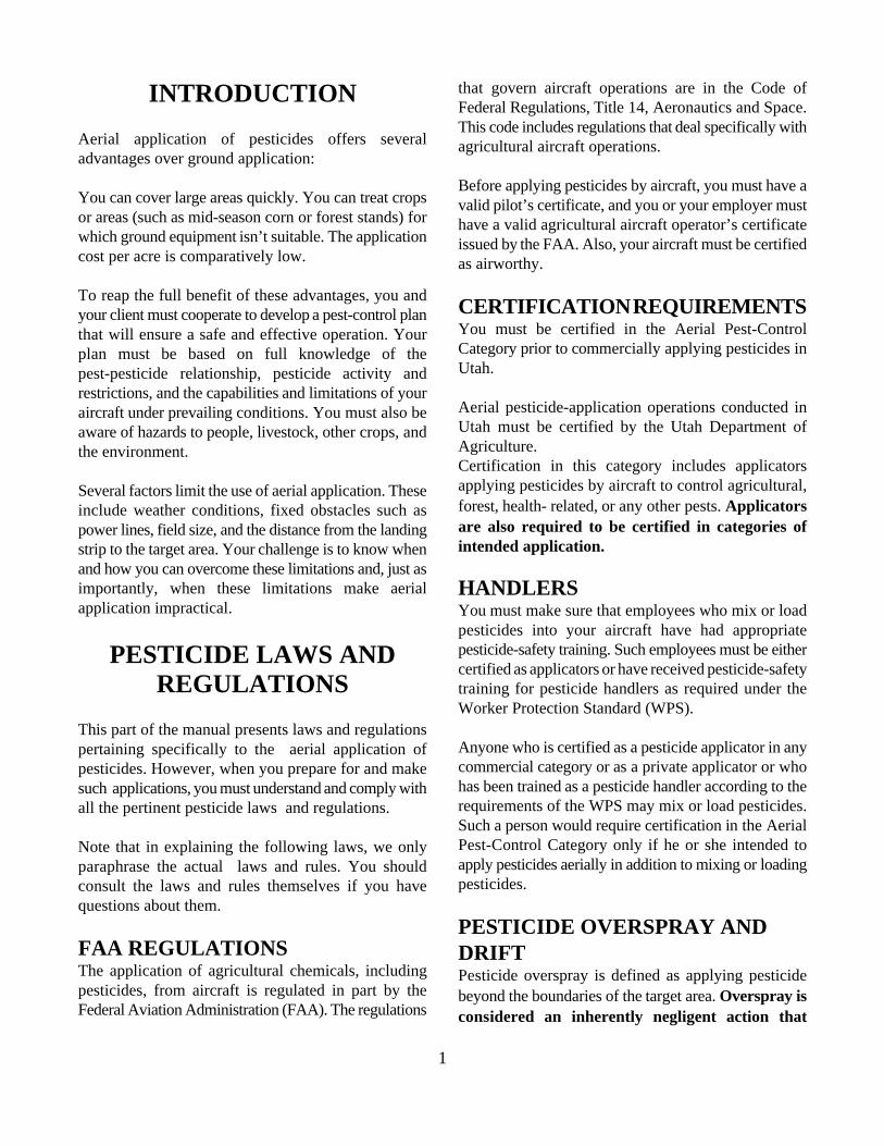
Centrifugal pump. The pump most widely used forspraying is the centrifugal pump (Figure 2). It’s availablein many sizes, handles all kinds of liquid formulationswith minimum wear, and can be operated without apressure-relief valve.
Figure 2. A centrifuge pump.
Centrifugal pumps that deliver a high flow rate whenusing a low operating pressure are generally used. Suchpumps are preferred because the spray-system pressure
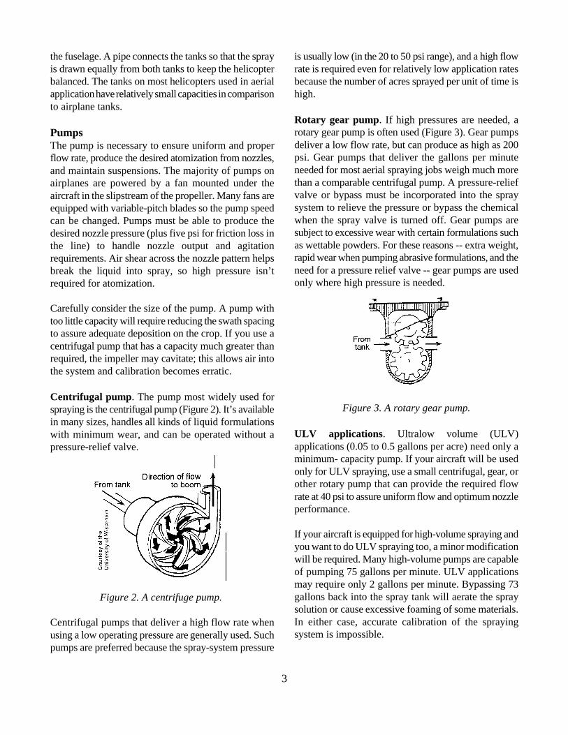
Rotary gear pump. If high pressures are needed, arotary gear pump is often used (Figure 3). Gear pumpsdeliver a low flow rate, but can produce as high as 200psi. Gear pumps that deliver the gallons per minuteneeded for most aerial spraying jobs weigh much morethan a comparable centrifugal pump. A pressure-reliefvalve or bypass must be incorporated into the spraysystem to relieve the pressure or bypass the chemicalwhen the spray valve is turned off. Gear pumps aresubject to excessive wear with certain formulations suchas wettable powders. For these reasons -- extra weight,rapid wear when pumping abrasive formulations, and theneed for a pressure relief valve -- gear pumps are usedonly where high pressure is needed.
Figure 3. A rotary gear pump.
ULV applications. Ultralow volume (ULV)applications (0.05 to 0.5 gallons per acre) need only aminimum- capacity pump. If your aircraft will be usedonly for ULV spraying, use a small centrifugal, gear, orother rotary pump that can provide the required flowrate at 40 psi to assure uniform flow and optimum nozzleperformance.
If your aircraft is equipped for high-volume spraying andyou want to do ULV spraying too, a minor modificationwill be required. Many high-volume pumps are capableof pumping 75 gallons per minute. ULV applicationsmay require only 2 gallons per minute. Bypassing 73gallons back into the spray tank will aerate the spraysolution or cause excessive foaming of some materials.In either case, accurate calibration of the sprayingsystem is impossible.

4
Installing a modification will make it possible to use the orifice size and materials being applied. The 20-meshsame spraying system for high-volume and ULV screens have the largest openings and would be usedapplications. with nozzles having a relatively large orifice. Nothing
Agitation SystemMany pesticide formulations require some form ofagitation during application to maintain the spraymixture. Recirculation of the spray mixture during ferrying to theworksite and during turnarounds is usually enough.When the aircraft is used to treat long fields whereturnarounds are limited, the pump must have sufficientcapacity to supply the boom and provide adequatebypass agitation. The return flow should wash thebottom of the tank to help prevent settling of pesticideresidue.
PlumbingAerial spray equipment must be designed with valves,piping, fittings and screens that are big enough for rapiddispersal of spray material.
Piping and fittings. Main piping and fittings shouldhave a large diameter (up to three inches) to apply highvolumes of liquids and a smaller diameter (about oneinch) for low-volume application; smaller piping canoften be used with helicopters because their slowerspeed makes it possible to get by with lower flow rates.The piping must be able to handle the pump pressure.
Hoses should be large enough to carry the desired flowand should be corrosion-resistant. They are less likely toblow off if the ends of the tubes are beaded or double-clamped. Avoid sharp bends in hoses as much aspossible, and change hoses when they swell or developsurface cracks.
Screens. Correctly sized line and nozzle screens mustprotect components from damage and nozzles fromclogging. The screens should be cleaned daily duringspray operation or whenever flow or pressure indicatesclogging.
Nozzle screen sizes of 20 to 100 mesh or an equivalentslotted strainer should be used, depending on nozzle
finer than 50-mesh screens should be used with wettablepowders.
Line screens should be of coarser mesh than nozzlescreens and should be located between the tank andpump and/or between the pump and boom. Locating theline screen between the tank and pump will protect thepump from damage; this screen, located in the suctionline, should have large mesh openings.
Figure 4. A positive cut-off spray valve.
Valves. Use a positive cut-off valve in the line toeliminate dripping when shutting off the spray at the endof the runs or when flying over pastures, lakes, streams,and other sensitive areas. A positive cut-off valve thatincorporates the suck-back feature (Figure 4) reducesthe risk of dripping nozzles. (Nozzle check valves will bediscussed later.) Suck-back is lost if the tank is empty orthe pump is off.
Pressure gauges. Attach the pressure-gauge sensingline near or at the boom to more accurately determinenozzle pressure. The ideal location for the pressure gauge is ina position where you can easily monitor pumpperformance from the cockpit. Because the flow of theliquid is related to the pressure, the pressure should bemaintained throughout a spraying operation. Pressuregauges can malfunction or the sensing line can partiallyplug. Check gauges periodically against a gauge youknow is accurate.
Pressure gauges are obviously valuable instruments formonitoring pump and nozzle performance. However,don’t rely solely on pressure gauges to calibrate an

5
aircraft. Nozzle manufacturers' tables give the gallons type. For ULV applications, flat-fan nozzles or rotaryper minute of water emitted by a particular nozzle at atomizers are often used.various pressures, but the actual output will vary fromaircraft to aircraft. An applicator who calibrates an Position the nozzles (and booms) so the spray won’taircraft using nozzles and pressure settings from catalog strike any part of the aircraft or the boom attachments.values will often be in for a surprise. Field checking your If the spray does strike any structural member of theaircraft's spray output and pattern is always advisable. aircraft, it will:
BoomsThe boom supports nozzles along the wingspan of anairplane. It may be round, airfoil-shaped or streamlined.Booms should be located behind and below the trailingedge of the wing to reduce drag and to place the nozzlesin cleaner airflow. Drop booms are often used to helpkeep nozzles in clean air. Research shows that the lowerposition is likely to give a better deposit pattern. Endcaps for booms should be removable for cleaning.
A boom about three-fourths as long as the wingspan ispreferable, because nozzles placed farther toward the tiphave a large amount of their output entrained in thewing-tip vortex and contribute to drift problems.Location of outboard nozzles on booms is critical,because wing tip and main rotor vortices (discussed inthe next section) influence pattern width and drift.Research has shown that nozzles placed outboard of thethree-fourths wingspan point contribute little towardincreasing swath width.
NozzlesIn ground application, the spray pattern from eachindividual nozzle is a major factor in distributing sprayuniformly across the swath. In aerial application, spraydistribution across the swath is affected considerably byaircraft wake; thus, it’s the overall pattern of all nozzles,rather than the individual pattern of each nozzle, whichis important. Therefore, nozzle features affecting spraydroplet size, droplet distribution, flow rate, and tendencyto clog are more critical than they would be for a groundsprayer.
Usually, the same nozzle tips, discs and cores, caps andscreens are used on both aerial- and ground-applicationequipment. The most commonly used spray system forhigher application rates is a boom with hydraulic conenozzles. The cone nozzles used most often in aerialapplication are the disc-core type and the whirl chamber
! Collect and fall off in large drops.! Distort the spray pattern.! Waste material. ! Cause corrosion of aircraft parts.
Ideally, the boom should have an end nozzle. However,if the outermost nozzle isn’t at the end of the boom,make provisions to purge the air trapped in the outerends of the boom. Trapped air will cause the spray tocontinue flowing after the spray valve is closed. Toeliminate trapped air, use a tee to attach each outboardnozzle to the boom and connect a small bleed line fromthe tee to the end of the boom. This will ensure rapidfilling of the boom, immediate flow from each nozzle,and quick and positive cutoff when the spray valve isclosed.
Rotary atomizers. Rotary nozzles allow you morecontrol over the size of the droplets released. Spraydroplets are formed by toothed, grooved, spinning discsor cups. Centrifugal force generated by the spinningaction causes the release of spray droplets. The speedat which the nozzle turns and the liquid flow rate controlthe size of the droplets. Rotary nozzles reduce the rangeof droplet sizes being applied, so very small and verylarge droplets are eliminated. However, they cangenerate a range of droplet sizes, enabling you to use thesame nozzles for coarse or fine sprays. Control ofdroplet size with rotary spray nozzles is especiallysignificant when oil carriers are used.
Rotary nozzles can apply a wide range of applicationrates. Because they have a relatively large meteringorifice, these nozzles don't clog as easily as conventionalnozzles when applying low-volume sprays with a highconcentration of chemicals in suspension.
You may need to fly up to 25 feet above the target toobtain a uniform deposit pattern. Uniformity alsodepends on how fine the spray is and the spacing of the
6
nozzles. For low-level work, six or more nozzles are Dry materials are dispensed from an airplane hopperrequired to provide a uniform swath. through a spreader mounted below the fuselage. The
Microfoil boom A microfoil boom can be used onhelicopters to control droplet size. It’s most often usedfor treating rights-of-way. This boom consists of a seriesof six-inch-long, airfoil-shaped nozzles. Sixty needleliketubes project from the trailing edge of each nozzle.Spray pressure and orifice diameter control droplet size.Droplets are formed on the needlelike tubes and pulledoff by the airstream, then they enter the non-turbulentair behind the nozzle. The microfoil boom is specificallydesigned for helicopters, because droplet size can’t bemaintained at high speeds. It can’t be used forhigh-viscosity sprays or wettable powders, because theorifices tend to clog.
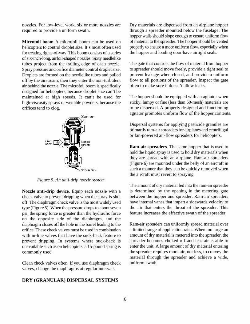
Figure 5. An anti-drip nozzle system.
Nozzle anti-drip device. Equip each nozzle with acheck valve to prevent dripping when the spray is shutoff. The diaphragm check valve is the most widely usedtype (Figure 5). When the pressure drops to about sevenpsi, the spring force is greater than the hydraulic forceon the opposite side of the diaphragm, and thediaphragm closes off the hole in the barrel leading to theorifice. These check valves must be used in combinationwith in-line valves that have the suck-back feature toprevent dripping. In systems where suck-back isunavailable such as on helicopters, a 15-pound spring iscommonly used.
Clean check valves often. If you use diaphragm checkvalves, change the diaphragms at regular intervals.
DRY (GRANULAR) DISPERSAL SYSTEMS
hopper walls should slope enough to ensure uniform flowof material to the spreader. The hopper should be ventedproperly to ensure a more uniform flow, especially whenthe hopper and loading door have airtight seals.
The gate that controls the flow of material from hopperto spreader should move freely, provide a tight seal toprevent leakage when closed, and provide a uniformflow to all portions of the spreader. Inspect the gateoften to make sure it doesn’t allow leaks.
The hopper should be equipped with an agitator whensticky, lumpy or fine (less than 60-mesh) materials areto be dispersed. A properly designed and functioningagitator promotes uniform flow of the hopper contents.
Dispersal systems for applying pesticide granules areprimarily ram-air spreaders for airplanes and centrifugalor fan-powered air-flow spreaders for helicopters.
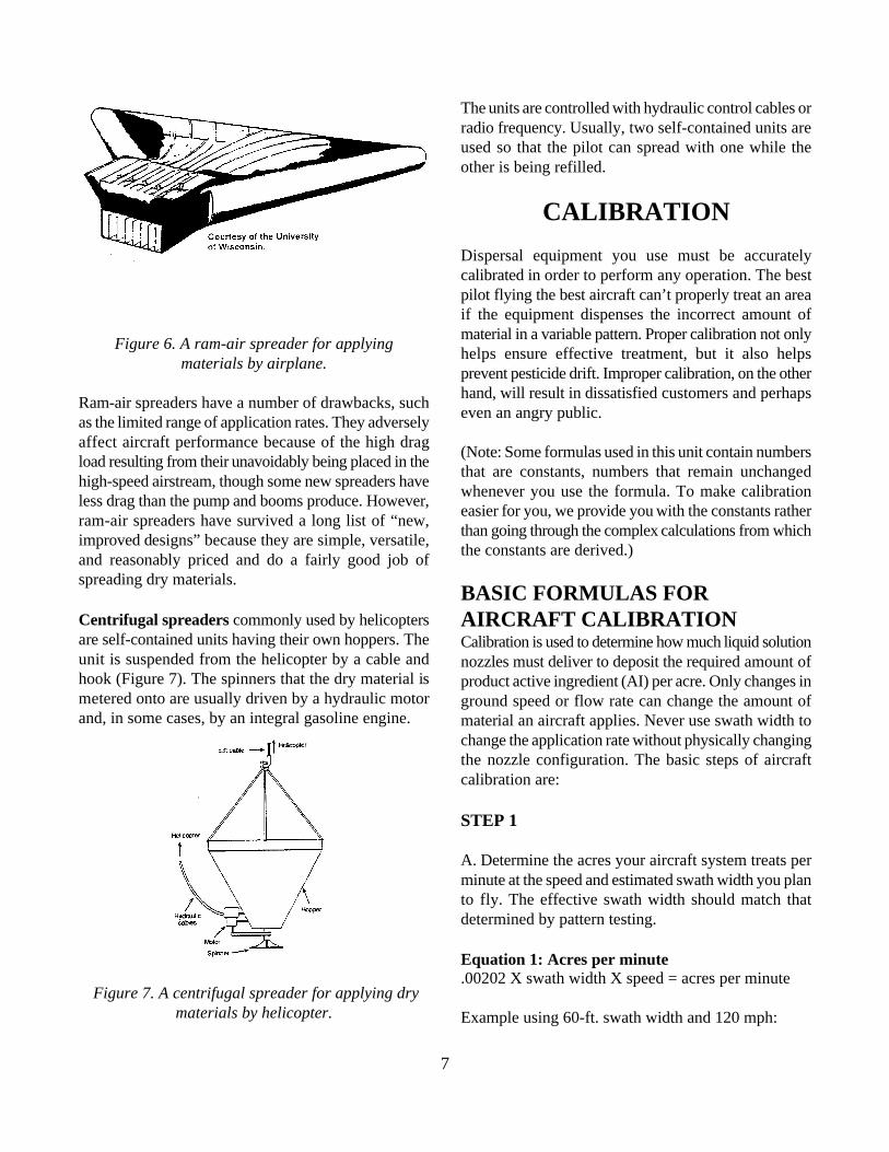
Ram-air spreaders. The same hopper that is used tohold the liquid spray is used to hold dry materials whenthey are spread with an airplane. Ram-air spreaders(Figure 6) are mounted under the belly of an aircraft insuch a manner that they can be quickly removed whenthe aircraft must revert to spraying.
The amount of dry material fed into the ram-air spreaderis determined by the opening in the metering gatebetween the hopper and spreader. Ram-air spreadershave internal vanes that impart a sidewards velocity tothe air that enters the throat of the spreader. Thisfeature increases the effective swath of the spreader.
Ram-air spreaders can uniformly spread material overa limited range of application rates. When too large anamount of dry material is metered into the spreader, thespreader becomes choked off and less air is able toenter the unit. A large amount of dry material enteringthe spreader requires more air, not less, to convey thematerial through the spreader and achieve a wide,uniform swath.
7
Figure 6. A ram-air spreader for applyingmaterials by airplane.
Ram-air spreaders have a number of drawbacks, suchas the limited range of application rates. They adverselyaffect aircraft performance because of the high dragload resulting from their unavoidably being placed in thehigh-speed airstream, though some new spreaders haveless drag than the pump and booms produce. However,ram-air spreaders have survived a long list of “new,improved designs” because they are simple, versatile,and reasonably priced and do a fairly good job ofspreading dry materials.
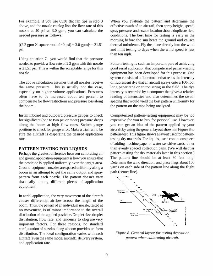
Centrifugal spreaders commonly used by helicoptersare self-contained units having their own hoppers. Theunit is suspended from the helicopter by a cable andhook (Figure 7). The spinners that the dry material ismetered onto are usually driven by a hydraulic motorand, in some cases, by an integral gasoline engine.
Figure 7. A centrifugal spreader for applying drymaterials by helicopter.
The units are controlled with hydraulic control cables orradio frequency. Usually, two self-contained units areused so that the pilot can spread with one while theother is being refilled.
CALIBRATION
Dispersal equipment you use must be accuratelycalibrated in order to perform any operation. The bestpilot flying the best aircraft can’t properly treat an areaif the equipment dispenses the incorrect amount ofmaterial in a variable pattern. Proper calibration not onlyhelps ensure effective treatment, but it also helpsprevent pesticide drift. Improper calibration, on the otherhand, will result in dissatisfied customers and perhapseven an angry public.
(Note: Some formulas used in this unit contain numbersthat are constants, numbers that remain unchangedwhenever you use the formula. To make calibrationeasier for you, we provide you with the constants ratherthan going through the complex calculations from whichthe constants are derived.)
BASIC FORMULAS FORAIRCRAFT CALIBRATIONCalibration is used to determine how much liquid solutionnozzles must deliver to deposit the required amount ofproduct active ingredient (AI) per acre. Only changes inground speed or flow rate can change the amount ofmaterial an aircraft applies. Never use swath width tochange the application rate without physically changingthe nozzle configuration. The basic steps of aircraftcalibration are:
STEP 1
A. Determine the acres your aircraft system treats perminute at the speed and estimated swath width you planto fly. The effective swath width should match thatdetermined by pattern testing.
Equation 1: Acres per minute.00202 X swath width X speed = acres per minute
Example using 60-ft. swath width and 120 mph:

8
.00202 X 60 ft. X 120 mph = 14.54 acres/minute Based on this calculation, select a nozzle that has a flow
B. Determine the gallons you must spray per minute to to 30 psi.apply the recommended gallonage rate.
Equation 2: Gallons per minute Acres per minute X application rate = gpm
Example using 10 gallons per acre:
14.54 a/min. X 10 gpa = 145.4 gpm
C. Once you have determined the flow rate, select thenozzle orifice size and number of nozzles needed todeliver the correct number of gallons per minute withinthe allowable operating-pressure range of your system.It’s generally recommended that spray pressuresremain greater than 18 psi and less than 40 psi(preferably 18 to 30 psi to minimize drift).
STEP 2
Determine the number of nozzles to use. Assume youare using a nozzle with a flow rate of 3 gpm at 25 psi.
Equation 3: Nozzles needed Total flow ÷ gpm per nozzle = number of nozzles needed
145.4 gpm ÷ 3 gpm per nozzle = 48.46 nozzles needed
To obtain the desired application rate at a three-gpmflow rate, you would need 48 operating nozzles. Positioneach nozzle and test the system pattern to verifydistribution pattern uniformity and required nozzle-pattern changes.
STEP 3
Determine what nozzle tip size to use. For thiscalculation, you must select the total number of nozzle-outlet positions on the boom or the total number ofpositions before calculations begin. Assume that 66nozzles are needed.
Equation 4: gpm per nozzleTotal flow ÷ number of nozzles = gpm per nozzle
145.4 gpm ÷ 66 nozzles = 2.2 gpm per nozzle
rate close to 2.2 gpm in the desired pressure range of 18
Once individual nozzles are mounted on a boom system,calculating flow rates is hard, especially if you’reequipping an aircraft for high application rates. Individualnozzle flow rates vary depending on location, turbulencein the boom, and the number of boom restrictions. Afteryou place the nozzles on the boom, make a trial run tobe sure you are applying the correct rate and depositingthe spray uniformly.
A high number of larger nozzles (larger orifices) resultsin high fluid velocities inside the boom and a largepressure drop from the center of the boom to the end ofthe boom where the last nozzle is located. This pressuredifferential may result in narrower effective swathwidths. Full three-inch liquid systems (no restrictionssmaller than three inches from the pump outlet on) arerecommended for field applications greater than ninegpa. The exact flow rate (gpm) or pressure (psi) neededfor a particular nozzle may not be listed in the availabletables. If you know the flow rate at one pressure, youcan calculate the pressure or flow rate for otherpressures or flow rates by using the following equation:
Equation 5: Flow rates and pressuresgpm ÷ gpm = square root of psi ÷ square root of psi1 2 1 2
If you know the desired pressure, you can calculate theunknown nozzle flow rate by rearranging the aboveequation as follows:
Equation 6: gpm at desired pressure(square root of gpm known) X (square root of psidesired) ÷ square root of psi known = gpm unknown
Or, if you know what flow rate you want, you can findthe pressure you need by rearranging Equation 6 asfollows:
Equation 7: Pressure at desired gpm[(gpm desired X (square root of psi known) ÷ (gpmknown)] = psi unknown2
This relationship between pressure and flow rate isaccurate for most hydraulic nozzles.
9
For example, if you use 6530 flat fan tips in step 3 When you evaluate the pattern and determine theabove, and the nozzle catalog lists the flow rate of this effective swath of an aircraft, then spray height, speed,nozzle at 40 psi as 3.0 gpm, you can calculate the spray pressure, and nozzle location should duplicate fieldneeded pressure as follows: conditions. The best time for testing is early in the
[(2.2 gpm X square root of 40 psi) ÷ 3.0 gpm] = 21.51 thermal turbulence. Fly the plane directly into the wind2
psi and limit testing to days when the wind speed is less
Using equation 7, you would find that the pressureneeded to provide a flow rate of 2.2 gpm with this nozzle Pattern-testing is such an important part of achievingis 21.51 psi. This is within the acceptable range for this good aerial application that computerized pattern-testingnozzle. equipment has been developed for this purpose. One
The above calculation assumes that all nozzles receive of fluorescent dye that an aircraft sprays onto a 100-footthe same pressure. This is usually not the case, long paper tape or cotton string in the field. The dyeespecially on higher volume applications. Pressures intensity is recorded by a computer that gives a relativeoften have to be increased about ten percent to reading of intensities and also determines the swathcompensate for flow restrictions and pressure loss along spacing that would yield the best pattern uniformity forthe boom. the pattern on the tape being analyzed.
Install inboard and outboard pressure gauges to check Computerized pattern-testing equipment may be toofor significant (one to two psi or more) pressure drops expensive for you to buy for personal use. However,along the boom at high flow rates. Switch gauge you can get an idea of the pattern applied by yourpositions to check for gauge error. Make a trial run to be aircraft by using the general layout shown in Figure 8 tosure the aircraft is dispersing the desired application pattern-test. This figure shows a layout used for pattern-rate. testing dry materials. For liquids, use a continuous piece
PATTERN TESTING FOR LIQUIDSPerhaps the greatest difference between calibrating airand ground application equipment is how you ensure thatthe pesticide is applied uniformly over the target area.Ground-equipment nozzles are spaced uniformly along aboom in an attempt to get the same output and spraypattern from each nozzle. The pattern doesn’t varydrastically among different pieces of applicationequipment.
In aerial application, the very movement of the aircraftcauses differential airflow across the length of theboom. Thus, the pattern of an individual nozzle, tested atno movement, is of minor importance to the overalldistribution of the applied pesticide. Droplet size, dropletdistribution, flow rate, and tendency to clog are veryimportant factors. For these reasons, no standardconfiguration of nozzles along a boom provides uniformdistribution. The ideal configuration varies with eachaircraft (even the same model aircraft), delivery system,and application rate.
morning before the sun heats the ground and causes
than ten mph.
system consists of a fluorometer that reads the intensity
of adding machine paper or water-sensitive cards ratherthan evenly spaced collection pans. (We will discusspattern-testing for dry materials later in this section.)The pattern line should be at least 80 feet long.Determine the wind direction, and place flags about 100yards on each side of the pattern line along the flightpath (center line).
Figure 8. General layout for testing depositionpattern when calibrating aircraft.

10
Regardless of which testing system you use, make surethat the boom and all nozzles, screens, and other parts ofthe spraying system are clean and rinsed before you testthe aircraft. Fill the spray tank with about 30 gallons ofwater, and add enough water-soluble dye to make adark solution. Fly a short pass to purge the boom of anyclear water and check for leaks.
You could also do this on the ground by attaching agarden hose to the end of the boom. The hose, usingexternal pressure, will force water containing dyethrough the boom and out of the nozzles. Turn off thehose and see if any nozzles continue to drip after thepressure is off. The dye will make any leaks or pluggeddrop-pipes easy to spot. Figure 9. Effective swath width of a typical
After takeoff, purge the boom and make sure that dyeleaves the end nozzles. Align the aircraft with the flagson a spray run that duplicates the actual field practices.Spray at least 100 yards on both sides of the pattern linewhile maintaining straight and level flight to ensure arepresentative spray pattern. Repeat the test to makesure the run was representative of typical spraydeposition.
Visual evaluation requires some experience, but youshould be able to identify common problems with sprayuniformity and swath width. Watch for light drop-densityareas around the centerline and uneven densities towardthe wing tips.
The effective swath width will be considerably narrowerthan the distance between the outside samples wheredye is evident (Figure 9). The amount of dye isreasonably constant for some distance on each side ofthe flight path and then begins to reduce until there is nodye evident. The effective swath width is the distancebetween the two points on the sloping ends of thepattern where the dye level is one-half the amount at thebeginning of the slope.
deposition pattern.
FACTORS THAT AFFECT DISPOSITIONPATTERNA number of factors influence swath width andapplication uniformity. Some, such as wing tip or rotorvortex, result from equipment design and must alwaysbe taken into consideration. Others, such as nozzleproblems, are maintenance problems that can becorrected. You can detect each of these problems withpattern testing. Next we will discuss how to diagnose,compensate for, or correct these and other commoncauses of non-uniform spray deposition.
Leaks. The dye makes it relatively easy for you todetect system leaks. If there are indications of systemleaks, such as very large drops of dye on the paper usedfor pattern evaluation, check the spray systemthoroughly.
Nozzle problems. It’s normal for small and largedroplets to appear on the sampling paper when patterntesting, because all atomizers generate a range ofdroplet sizes. If the range of droplets variestremendously between locations in the pattern, different-sized or badly worn nozzles may be the problem. (Youwill generally find finer droplets in the center of thepattern that are caused by the increased shear action ofthe high-speed prop blast.)
Sometimes, you may put different-sized nozzles on theboom on purpose. For example, you may use a fewnozzles with larger openings to counter prop wash

11
displacement. Nozzle wear usually doesn’t affect spray speed, and special cowlings such as speed rings, spraypattern significantly. You are likely to notice that you are droplet size, and spraying height.spraying too great a volume before the wear gets badenough to have a significant impact on the pattern. Helicopters exhibit similar rotor-wash characteristics.
Incorrect droplet spectrum. It’s impossible todetermine the size of droplets that are generated by anatomizer by measuring the droplet stain on the samplingpaper. However, an experienced operator can determinewhether droplet size is appropriate for the job to bedone. Generally, coarse droplets are used for applyingherbicides, small to medium for insecticides, and smallfor fungicides.
EFFECTS OF EQUIPMENT DESIGN ANDCONFIGURATIONAirplanes and helicopters must move air to fly. Theresulting air movement isn’t uniform, but it’s somewhatpredictable. Your challenges are to understand how airmoves around and under the aircraft and to compensatefor this movement in order to apply pesticides uniformlyacross the swath.
Again, although we mention some general guidelines forproducing a uniform spray pattern, remember that theactual placement of nozzles varies with each individualaircraft. There’s no standard configuration of nozzlesthat will provide a uniform pattern.
Prop and rotor wash. Prop-wash turbulence, which isthe result of the clockwise propeller air helix spiralinginto the fuselage, carries droplets from nozzles to theright of the fuselage and deposits them on the targetlocated beneath or to the left of the fuselage.Counterclockwise-rotation propellers (used withcounterclockwise-rotating engines such as the PZL)have similar but reversed prop-wash problems, with theexcess deposit on the opposite right side of the aircraft.
Prop wash results in a lack of spray deposit reachingtargets from the center to about six feet right (or left inthe case of the PZL engines) of the fuselage.Historically, a high percentage of the aircraft testedduring aerial- application workshops have requiredcompensation for this problem. The seriousness of prop-wash spray shift depends on factors that include aircraftfuselage and aerodynamics, propeller length and rotation
The rotation of the rotor creates a swirling, cone-shapedhelix that descends, trailing the direction of flight. Thisrotating air mass traps small spray droplets andtransports them, resulting in a distortion of the spraydeposit away from the leading rotor and in the directionof the trailing rotor. This shift may be influenced bymany factors, including aircraft aerodynamics, locationof boom mounting, spray droplet size, forward flightspeed, and weight of the aircraft.
Prop wash is anticipated in propeller aircraft, especiallythose with larger radial engines. Some compensation ispossible if nozzles are located correctly. Install extranozzles to the right of the fuselage, in line with or justinboard of a point directly behind the center of thepropeller.
To determine this point, align the propeller horizontally,and visualize a line parallel to the line of flight rearwardto the spray boom. Radial-powered Ag Cats typicallyrequire more nozzles on the right than other types ofaircraft. Engine speed rings alter the airflow around theengine and result in different distortions to the depositionpatterns than the same aircraft without a speed ring.The deposition pattern of the large Melex Dromaderaircraft is especially sensitive to the addition of third-party-manufactured speed rings. After adding orrelocating any nozzle position, pattern-test the aircraft toverify the change in deposition uniformity (Figure 10).
Wing-tip vortex. Wing-tip vortex originates in theturbulence behind the wing as the airstream movesquickly from the high-pressure area under the wing andmeets the low-pressure air from the top of the wingsurface. The air mass travels the shortest route, whichcauses part of the air to slip outward from under thewing and introduces a large amount of turbulence androtation. Visualize this rotation as a spinning cone of airwith the highest velocities toward the center of the cone.
The highest-velocity (strongest) vortex action isproduced by heavy, slow-moving aircraft. Bi-wingaircraft produce vortices at each of the wing tips thatquickly combine into a single vortex behind the aircraft.
12
The combined vortex is about equal in strength to thatproduced by a monowing aircraft of the same weightand air speed.
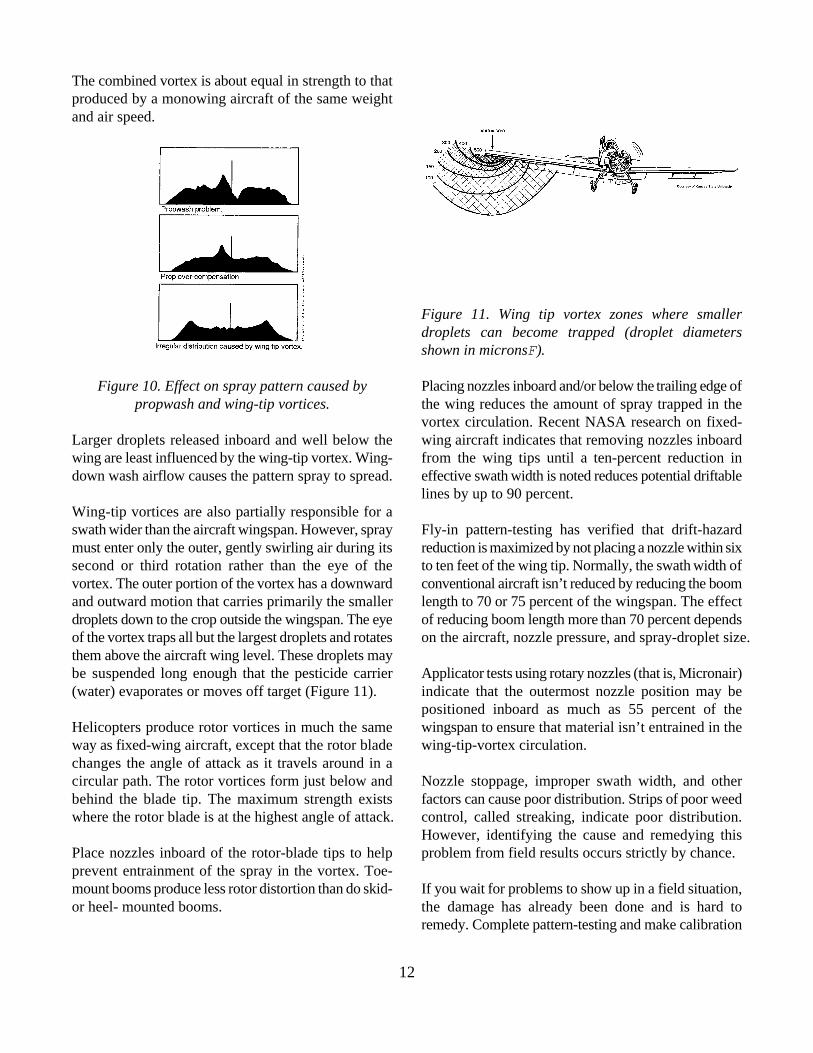
Figure 10. Effect on spray pattern caused by Placing nozzles inboard and/or below the trailing edge ofpropwash and wing-tip vortices. the wing reduces the amount of spray trapped in the
Larger droplets released inboard and well below the wing aircraft indicates that removing nozzles inboardwing are least influenced by the wing-tip vortex. Wing- from the wing tips until a ten-percent reduction indown wash airflow causes the pattern spray to spread. effective swath width is noted reduces potential driftable
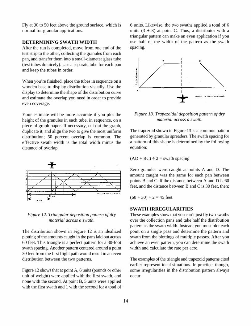
Wing-tip vortices are also partially responsible for aswath wider than the aircraft wingspan. However, spray Fly-in pattern-testing has verified that drift-hazardmust enter only the outer, gently swirling air during its reduction is maximized by not placing a nozzle within sixsecond or third rotation rather than the eye of the to ten feet of the wing tip. Normally, the swath width ofvortex. The outer portion of the vortex has a downward conventional aircraft isn’t reduced by reducing the boomand outward motion that carries primarily the smaller length to 70 or 75 percent of the wingspan. The effectdroplets down to the crop outside the wingspan. The eye of reducing boom length more than 70 percent dependsof the vortex traps all but the largest droplets and rotates on the aircraft, nozzle pressure, and spray-droplet size.them above the aircraft wing level. These droplets maybe suspended long enough that the pesticide carrier Applicator tests using rotary nozzles (that is, Micronair)(water) evaporates or moves off target (Figure 11). indicate that the outermost nozzle position may be
Helicopters produce rotor vortices in much the same wingspan to ensure that material isn’t entrained in theway as fixed-wing aircraft, except that the rotor blade wing-tip-vortex circulation.changes the angle of attack as it travels around in acircular path. The rotor vortices form just below and Nozzle stoppage, improper swath width, and otherbehind the blade tip. The maximum strength exists factors can cause poor distribution. Strips of poor weedwhere the rotor blade is at the highest angle of attack. control, called streaking, indicate poor distribution.
Place nozzles inboard of the rotor-blade tips to help problem from field results occurs strictly by chance. prevent entrainment of the spray in the vortex. Toe-mount booms produce less rotor distortion than do skid- If you wait for problems to show up in a field situation,or heel- mounted booms. the damage has already been done and is hard to
Figure 11. Wing tip vortex zones where smallerdroplets can become trapped (droplet diametersshown in micronsF).
vortex circulation. Recent NASA research on fixed-
lines by up to 90 percent.
positioned inboard as much as 55 percent of the
However, identifying the cause and remedying this
remedy. Complete pattern-testing and make calibration

13
adjustments to the aircraft to obtain uniform deposition [(acres per mile) X 60] ÷ seconds to fly 1 mile = acresbefore you make annual applications. per minute
CALIBRATION CALCULATIONSFOR SOLIDSGive equal attention to calibrating equipment thatdispenses solids and liquids. The type of spreader, typeof granular material, rate per acre, and amount of swathoverlap all affect calibration accuracy. If one conditionchanges, you must repeat the calibration procedure. Forexample, the size, shape, density and flowability of agranular material affects the swath width, applicationrate and pattern. Also, except at low rates, swath widthis inversely proportional to application rate; that is, if youincrease the rate, you decrease the swath width.
If the spreader manufacturer provided an owner'smanual that specifies gate settings for different deliveryrates and for different formulations, use this data as astarting point. Determine the actual pounds per minuteby conducting a hopper-refill test during the applicationof the first few swaths of material. (Hopper-refill testsare discussed later in this section.)
Assume a swath width based on previous experiencewith similar equipment. Once you know the flying speed,you can calculate the desired rate per minute.
Equation: 3600 ÷ mph = seconds to fly 1 mile
Example: If you assume a speed of 90 mph and a swath width of50 feet:
3600 ÷ 90 mph = 40 seconds
Equation:Swath width (feet) ÷ 8.25 = acres covered per mile
Example:50 ÷ 8.25 = 6.06 acres per mile
You can then calculate acres per minute as follows:
Equation:
Example:(6.06 X 60) ÷ 40 = 9.09 acres per minute
If the label calls for 10 pounds per acre, the desired flowrate is:
Equation:(pounds per acre) X (acres per minute) = pounds perminute
Example:(10) X (9.09) = 90.9 pounds per minute
If you don't have information regarding proper gatesettings, do some preliminary work on the ground. Timethe flow of 100 pounds of granules through the gateopening. The flow rate will be about twice as fast duringflight; use this to make an estimate, and adjust the gatefor the desired rate per acre.
For example, suppose in your ground test, it took twominutes for 100 pounds to flow through the gateopening. That would correspond to 100 pounds perminute while in flight. This output is too high; readjustthe gate opening and try again. When the value obtainedin the ground test is acceptable, check the distribution bydoing a test run.
PATTERN TESTING FOR DRY MATERIALSYou can determine the distribution pattern only bysetting out pans across a line of flight. The setup issimilar to that shown for liquid sprays in Figure 8 onpage 14. The pans should be at least four inches deepand padded inside with a thin layer of foam. The insidearea should be sufficient to catch a measurable amountof material. (For example, a 16-square-foot pan willcatch up to half an ounce if you apply granules at 100pounds per acre.) Place them at two-foot intervals for20 feet on each side of the swath centerline and atfive-foot intervals for an additional 30 feet on each side.Do this on flat ground, and be sure the total width isgreater than the expected swath width.
Perform the test during minimum wind conditions. Orientthe pans at right angles to the wind and fly into the wind.
14
Fly at 30 to 50 feet above the ground surface, which is 6 units. Likewise, the two swaths applied a total of 6normal for granular applications. units (3 + 3) at point C. Thus, a distributor with a
DETERMINING SWATH WIDTHAfter the run is completed, move from one end of thetest strip to the other, collecting the granules from eachpan, and transfer them into a small-diameter glass tube(test tubes do nicely). Use a separate tube for each panand keep the tubes in order.
When you’re finished, place the tubes in sequence on awooden base to display distribution visually. Use thedisplay to determine the shape of the distribution curveand estimate the overlap you need in order to provideeven coverage.
Your estimate will be more accurate if you plot theheight of the granules in each tube, in sequence, on apiece of graph paper. If necessary, cut out the graph,duplicate it, and align the two to give the most uniformdistribution; 50 percent overlap is common. Theeffective swath width is the total width minus thedistance of overlap.
Figure 12. Triangular deposition pattern of dry These examples show that you can’t just fly two swathsmaterial across a swath. over the collection pans and take half the distribution
The distribution shown in Figure 12 is an idealized point on a single pass and determine the pattern andplotting of the amounts caught in the pans laid out across swath from the plottings of multiple passes. After you60 feet. This triangle is a perfect pattern for a 30-foot achieve an even pattern, you can determine the swathswath spacing. Another pattern centered around a point width and calculate the rate per acre.30 feet from the first flight path would result in an evendistribution between the two patterns. The examples of the triangle and trapezoid patterns cited
Figure 12 shows that at point A, 6 units (pounds or other some irregularities in the distribution pattern alwaysunit of weight) were applied with the first swath, and occur.none with the second. At point B, 5 units were appliedwith the first swath and 1 with the second for a total of
triangular pattern can make an even application if youuse half of the width of the pattern as the swathspacing.
Figure 13. Trapezoidal deposition pattern of drymaterial across a swath.
The trapezoid shown in Figure 13 is a common patterngenerated by granular spreaders. The swath spacing fora pattern of this shape is determined by the followingequation:
(AD + BC) ÷ 2 = swath spacing
Zero granules were caught at points A and D. Theamount caught was the same for each pan betweenpoints B and C. If the distance between A and D is 60feet, and the distance between B and C is 30 feet, then:
(60 + 30) ÷ 2 = 45 feet
SWATH IRREGULARITIES
pattern as the swath width. Instead, you must plot each
earlier represent ideal situations. In practice, though,

15
After you plot the sample and determine the swath, formulation. They also won’t change appreciably fromcheck to see if the distribution of the granules remains ten to 20 pounds per acre. Thus, the same swath widthwithin acceptable tolerances (that is, where the amount can be used for this range of application rates, and anwithin each collection pan is within five percent of the annual check will be sufficient, provided that theaverage). equipment isn’t changed or damaged.
Non-symmetrical distribution pattern. A commontype of irregularity in the swath is non-symmetricaldistribution; that is, for any given swath, the pattern onthe right side of the aircraft is different from that on theleft.
If you fly all passes in the same direction in a race trackpattern, and there is 50 percent overlap, the left wingpattern comes over the right wing pattern (or vice versa)and results in a perfect total pattern. If you fly aback-and-forth pattern, the left wing overlaps the leftwing and the resulting pattern isn’t acceptable.
The goal of calibration is to make distribution patterns aseven as possible and the same on both sides of theaircraft. If you must adjust the pattern halfway out onthe left side, adjust the flow at the gate halfway left tocenter. Or you may have to adjust the spreader vaneshalfway left from center.
Determine the actual application rate. Afterchecking the swath width, pattern and calibration of thespreader, measure the application rate per acre. To dothis, load a known weight of pesticide product into thehopper. Fly a known number of passes of known length(minimum four passes, two in each direction), thenweigh the remaining material. The initial weight minusthat of the remaining material is the amount you applied.
You can determine the acres covered in the test run asfollows:
Number of swaths X field length (ft.) X swath width(ft.) ÷ 43,560 sq. ft. per acre = acres covered
The application rate is:
Pounds of material applied in the test run ÷ acrescovered in the test run = pounds per acre
Once you determine the swath width and pattern, theyusually won’t change for the same plane, spreader and
Still, you should check the application rate whenever youget a chance. Such checking shows exactly how manypounds were applied for each job. Calculate the rate peracre to check on the gate setting several times a day,and keep records of your checks. Many things canhappen to affect the rate, including these:
! Foreign material may enter the hopper and plug agate or spreader opening.
! Moisture may condense in the hopper overnight.The resulting sticky material would affectapplication rate.
! Water may splash onto the spreader during taxi ortake-off and cause wet areas around the openings,thus reducing the flow of granules.
By continually checking your delivery rate andcorrecting any problems, you will consistently makeeffective and accurate applications.
FIELD OPERATIONS
Scout the field from the air before actually starting sprayoperations. Circle the field at a very low altitude, buthigh enough to clear all obstructions by at least 50 feet.Look for wires and other obstructions (trees, buildings,windmills, radio antennas, road signs, pipeline markersand fences) in and near the fields to be treated. Beaware that trees may conceal power lines. Regard anybreak in the cultivation pattern in the field with suspicion.
After you circle the field and note the obvious hazards,fly just above and to one side along each power orphone wire and check each pole. Look for branch wires,guy wires, and transformers. Many times a wire is hardto spot from above, but if you look at the pole tops youcan see the insulators that attach these wires to the pole.Transformers usually have a branch wire that goes to ahouse, well or other structure. If a house is near thetreatment area, look for a line coming in from
16
somewhere to determine by what route it gets its power.A guy wire will normally be placed on the opposite sideof a pole from a branch wire or at the pole where amain line makes a turn.
Always remember that conditions change. The wire youflew under last year (or last week, for that matter) mayhave a new one under it today. You may be able to getunder a wire in the spring when a crop is first planted,but not later in the year when the crop is taller. And afield that had no lines last week may have power orphone lines today. Heat expands wires, making themlower to the ground during hot summer days.
FLIGHT PATTERNSPractice safe flying procedures during application toprotect you, your ground crew, and the environment andto ensure that the pesticide you are applying will beeffective.
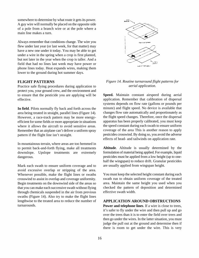
In field. Pilots normally fly back and forth across thearea being treated in straight, parallel lines (Figure 14).However, a race-track pattern may be more energy-efficient for some fields or more appropriate in situationswhere it allows the aircraft to avoid sensitive areas.Remember that an airplane can’t deliver a uniform spraypattern if the flight line isn’t straight.
In mountainous terrain, where areas are too hemmed into permit back-and-forth flying, make all treatmentsdownslope. Upslope treatments are extremelydangerous.
Mark each swath to ensure uniform coverage and toavoid excessive overlap or stripping of the area.Whenever possible, make the flight lines or swathscrosswind to assist in overlap and coverage uniformity.Begin treatments on the downwind side of the areas sothat you can make each successive swath without flyingthrough chemicals suspended in the air from previousswaths (Figure 14). Also try to make the flight lineslengthwise to the treated area to reduce the number ofturnarounds.
Figure 14. Routine turnaround flight patterns foraerial application.
Speed. Maintain constant airspeed during aerialapplication. Remember that calibration of dispersalsystems depends on flow rate (gallons or pounds perminute) and flight speed. No device is available thatchanges flow rate automatically and proportionately asthe flight speed changes. Therefore, once the dispersalapparatus has been properly calibrated, you must keepthe speed constant during each swath to ensure uniformcoverage of the area This is another reason to applypesticides crosswind. By doing so, you avoid the adverseeffects of head- and tailwinds on application rate.
Altitude. Altitude is usually determined by theformulation of material being applied. For example, liquidpesticides must be applied from a low height (up to one-half the wingspan) to reduce drift. Granular pesticidesare usually applied from wingspan height.
You must keep the selected height constant during eachswath run to obtain uniform coverage of the treatedarea. Maintain the same height you used when youchecked the pattern of deposition and determinedeffective swath width.
APPLICATION AROUND OBSTRUCTIONSPower and telephone lines. If a wire is close to trees,it’s safer to fly under the wire and then pull up and goover the trees than it is to enter the field over trees andthen go under the wires. In the latter situation, you mustjudge the pull out at the ground and determine then ifthere is room to get under the wire. This is very

17
dangerous. Don’t fly under wires that have fences or swath spacing or distance the aircraft must move over,other objects under them. maneuverability of the aircraft, power, load remaining,
Obstructions beside and at end of field. Ifobstructions (trees, power and telephone lines, orbuildings) are located at the beginning or end of theswath, turn the spray on late or shut it off early, perhapsone or two swath-widths from the end of the field. Thenwhen the field is completed, fly one or two swathscrosswise (parallel to the obstruction) to finish out thefield. Even though you may be over the target area, youmustn’t disburse materials when dropping in or pullingout of the field. The deposition pattern will be distortedand the pesticide will be likely to drift.
If there are obstructions along the sides of a field, flyparallel and as close to the obstruction as you safelycan. Leave an untreated border strip adjacent tobuildings, residences, and livestock areas to help avoidpesticide drift. You may treat obstructed borders whenthe wind is blowing toward the target area.
Obstructions within a field. Approach a tree, pole, orother obstruction that is within a field the same way youwould if it were at the end of the field -- stop sprayingone or two swath widths from the obstruction. Afterpulling up, make a 180-degree turn before dropping in onthe other side. This will allow you to control the speedsufficiently to avoid overshooting the other side. Workpast the obstruction, then run one or two swath widthson each side of it to complete the treatment around it.
THE TURNAROUNDThe turnaround is performed more often than any othermaneuver during aerial applications. When executedpoorly, it’s a major cause of accidents. The pullup anddownwind turn puts the aircraft in a low-speed,high-drag situation, so it must be executed carefully.You should never look back; accomplish orientation forthe next swath before the pullup.
If possible, start the turnaround at the end of each swathafter pulling up over obstructions. When applyingpesticides in the back-and-forth pattern, start theturnaround by turning 45 degrees downwind, leveling offfor several seconds, then making a smooth coordinatedreversal of 225 degrees (Figure 14). The number ofseconds you spend in level flight is determined by the
wind, temperature and elevation.
As you complete the turn, orient yourself to line up forthe next swath. Pilots often encounter difficulty duringthis part of the turn, so pace yourself. Avoid fast orintricate maneuvering to get into position. Complete theturnaround before dropping in over any obstructions onthe next swath. Any turning while dispensing will distortthe distribution pattern and make even applicationimpossible.
Avoid snapping reversal, lowball or wingover turns.When you must make a turn by going upwind first, youneed more space and time to complete the turn.
Avoid turnarounds over residences, farm buildings,penned poultry or livestock, watering places, ponds andreservoirs. Flying in a racetrack pattern may help youavoid these sensitive areas. Always stop the dischargebefore pulling up or making turnarounds.
APPLYING GRANULESAirspeeds of 100 to 120 mph (faster for some airplanes,slower for helicopters) are recommended when applyinggranules. These speeds maintain good airflow throughthe spreader and obtain proper distribution and maximumswath width. The flying height, airspeed, and correctground track must be held as constant as possible toobtain uniform results. Crosswinds have considerableeffect on offsetting the dispersal pattern from the groundtrack centerline because of the flying height required.Head or tail winds affect ground speed, and adjustmentsin flow rate and/or airspeed may be required to giveuniform distribution on alternating upwind-downwindpasses. Monitor operating conditions and weatherchanges carefully when you apply these materials,because a no-wind condition is seldom encountered forany length of time.
You can obtain maximum swath width at a certainwheel height above the crop. This height varies with thedensity, size and grading of the particles of materialbeing applied. For most materials, this is in the range of40 to 60 feet wheel height. Effective wheel height isdetermined by the lateral distance the spreader throwsthe heavier particles. Flying below this height allows

18
particles to hit the ground while still traveling in the ! Be acquainted with each chemical used, knowingspanwise direction. Flying above this height achieves no how to handle it safely, what clothing and devicesincrease in swath width because particles fall vertically should be worn for protection, antidotes that areafter the lateral energy is dissipated. Don’t fly higher required in the event of accidental overexposure,than necessary, or you may experience problems with special precautions that must be observed whenincreased swath displacement and difficulty in applying chemicals, where chemicals can be usedmaintaining desired ground-track height. safely, and the hazards if chemicals are applied
FERRYINGFly at an altitude of at least 500 feet during ferry flightsbetween the airstrip and worksite, whether the tanks areloaded or empty. Avoid flying over farm buildings,scattered residential areas, and penned poultry orlivestock. Too often, because of the noise they make ortheir mere presence, agricultural aircraft are accused ofdamaging or contaminating property. If you must makemany trips back to the same area, avoid taking the sameroute each time. Deviate one-eighth to one-fourth mileoff direct course to avoid flying close to the same areaseach time.
PROPER HANDLING ANDUSE
Every pesticide comes with its own set of risks tohumans and the environment. Everyone in youroperation has a responsibility to understand and avoidthese risks. If the risks are realized, you must know howto respond to them.
PILOTSThe pilot is responsible for efficient and successful aerialapplication. Training, ability, skill, judgment andcompetence can’t be overemphasized. A pilot must:
! Determine the best direction in which to spray ablock and adeptly maneuver an aircraft that isloaded to its maximum legal weight.
! Be trained in crop recognition, not only to ensurethat the correct field is treated but, moreimportantly, to ensure that any drift damage toadjacent crops is minimal.
! Read the label, and comply with application rate andsafety precautions.
incorrectly or in the wrong places.
! Know how weather affects the application ofsprays and granules to crops.
! Master his or her aircraft, using only the maneuversthat can be performed safely and avoiding others,and know the maximum load limit from short, rough,temporary airstrips.
Above all, the pilot must be aware of his or herown limitations in the aircraft.
Pilots should use extreme caution when loading aircraftwith pesticides. It’s hard, even with normal protectiveclothing and equipment, to load without some exposure.Accumulated exposures may bring on mild pesticidesymptoms, including dizziness and fixed contraction ofthe pupils (miosis) of the eye. The latter has beenreported to cause diminished visual acuity, especially atnight.
These mild symptoms may not be as serious to groundapplicators or the ground crew, but they are potentiallyfatal to a pilot, especially during night applications. Ifpilots are exposed when dispensing pesticides and duringloading operations, they may accumulate enough dosageto trigger symptoms. When crosswinds occur, the pilotshould begin application on the downwind side of thefield to avoid flying through the previous swath.
There is evidence that accidental, direct eyecontamination by organophosphates may causecontraction of the pupils for from seven to ten dayswithout any other symptoms. There have been severalreports of fatal injury to agricultural pilots who weredirectly exposed to organophosphates. Miosis wasdefinitely identified following the crash.
It’s very hard to prove that “pilot error” crashes werecaused by pesticide exposure, but present evidence

19
suggests pesticide exposures should be kept to a gloves in an enclosed container to prevent contaminationminimum. Pilots who exhibit symptoms characteristic of of the cockpit's interior.pesticide poisoning shouldn’t fly until the symptomsdisappear. Under the WPS, pilots may substitute certain protective
Remember, your body will tolerate small amounts of equipment. The substitutions that are allowed depend onmost pesticides. But if you accumulate doses of whether the cockpit is enclosed or open.pesticide from various operations -- flying, loading,mixing or cleaning, symptoms will begin when you reacha certain level.
There have been a number of air crashes after the pilotwas drenched with pesticide from a ruptured spray tank.Many pesticides are rapidly absorbed through the skin aswell as entering through the respiratory route. Alwaysremove contaminated clothing as soon as possible, thenrun for the nearest water for washing -- whether that isa ditch, creek, pond or hose. This isn’t the time formodesty. The California Department of Health reportedone pilot who, though not critically injured in the crash,was splashed with TEPP and phosdrin. He died oforganophosphate poisoning 20 minutes later.
Use a filter- or canister-type respirator appropriate forthe chemical being applied. If you need one for extendedperiods during hot weather, use a respirator andcrash-helmet combination that is ventilated with freshair.
PROTECTIVE CLOTHING ANDEQUIPMENTThe unit in Applying Pesticides Correctly provides anexcellent discussion of the types of, and need for,protective clothing and equipment. The WorkerProtection Standard (WPS) requires pesticidemanufacturers to list minimum personal protectiveequipment and clothing requirements on the label. Thelabel must specify the type of gloves to wear (such asnitrile) and, if applicable, the type of respirator to useand the respirator's MSHA/NIOSH approval-numberprefix. (For example, the label might say to use anorganic-vapor-removing cartridge and pre-filter withMSHA/NIOSH approval number prefix TC-23C.)
The WPS requires you to wear the protective glovesrequired by the labeling when entering or exiting anaircraft whose exterior is contaminated by pesticideresidue. Once inside the cockpit, you must keep the
gear for label-specified personal protective clothing and
Enclosed cockpits. Persons in enclosed cockpits arenot required to wear personal protective clothing orequipment, but they must wear long-sleeved shirts, longpants, shoes and socks.
Open cockpits. Persons in open cockpits must wearthe personal protective clothing and equipment requiredfor a ground applicator using that product, except thatchemical-resistant footwear isn’t required. You maysubstitute a helmet for chemical-resistant headgear anda visor for protective eyewear.
GROUND OR LOADING CREWMost pesticides are toxic in varying degrees. Theloading or ground crew has the most direct contact withpesticides and must wear protective clothing andequipment. The label on the pesticide specifies theprotection needed.
When you work around chemicals:
! Don’t breathe fumes from the mixer when you pourconcentrated chemicals into mixing equipment.Wear your respirator and face shield as required.
! Don’t eat your lunch or smoke around mixingequipment. Move out of the loading area, then washyour hands thoroughly.
! Don’t carry cigarettes or anything you eat in yourpocket while you load dust or liquid; they absorbchemical fumes.
! Chemicals can poison you by absorption through theskin, eyes or mouth or by breathing fumes. Protectyourself at all times.
! Triple-rinse or pressure-rinse chemical containersimmediately after emptying them.
20
! Never leave emptied chemical containers on an Point the airplane toward the runway while it’s beingunattended runway. Bring all containers back to loaded to avoid making sharp turns with a fully loadedwhere you normally dispose of them. Keep them airplane. Locate mixing tanks so that prop blast doesn’tunder lock and key, full or empty. blow sand or debris toward them. A wide, circular
! Stand upwind of mixing equipment when you pour area in the middle is often used. The fuel may also be inchemicals or while you wait for the airplane to the middle of the circle so you can refuel while loading;return for another load. however, remember to keep fuel and pesticides well
Wear protective clothing when you handlechemicals:
! Never handle insecticides without good, clean,unlined rubber gloves.
! Wear enough protective clothing to keep as much ofthe body unexposed to the chemical as possible.Liquid Category I and II chemicals require that youalso wear a waterproof apron when you mix andload.
! Don’t wipe your hands on your clothes; this willcontaminate them. Take a clean change of overallsto the job with you.
! Don’t wear dirty or contaminated clothes on the jobor home. Wash your clothing regularly.
! Wear good rubber footwear to avoid contaminationwith chemicals that are on the ground in the loadingarea.
! Dispose of emptied pesticide containers properly.
! Wash thoroughly with soap and water immediatelyif you accidentally spill chemicals on yourself.
Believe what you read on all labels. If you don’tcomply with them, you place yourself and others atgrave risk.
AIRSTRIP OPERATIONA well-organized airstrip ensures that the aircraft spendsthe minimum amount of time on the ground and themaximum time spraying. Airstrip layouts vary, but fuelsand pesticides must be kept well apart and protectedfrom sunlight and environmental extremes.
turnaround area with the chemical storage and mixing
apart.
Load the aircraft via a closed-transfer system. Do allground work on an impervious surface that allows anyaccidental spills to be contained, properly recovered, andused or disposed of.
You may need to reduce the aircraft payload from themanufacturer's maximum specification to compensatefor airstrip conditions or for the effect of atmosphericconditions.
AERIAL-APPLICATION CHECKLISTSWe suggest that pilots and crew, including flaggers,review a checklist at least weekly to help them avoidbecoming complacent and careless.
Pilot checklist. The pilot should do the followingbefore, during and after any application:
1. Don’t load or handle highly toxic pesticides,especially hazardous formulations, during anyoperation.
2. Turn off the engines during loading operations.
3. Wear an approved safety helmet, long-sleeved shirt,long pants, shoes, socks, and other protectiveequipment specified on the pesticide label.
4. Check the field and surrounding area before youapply chemicals to be sure there are no animals,humans, crops, waterways, streams or ponds thatmight be injured or contaminated either by directapplication or drift.
5. Don’t fly through the suspended spray of anapplication.
21
6. Stop treatment if winds rise and create a drifthazard.
7. Don’t turn on dispersal equipment or check the flowrate except in the area to be treated.
8. Refuse to fly if the customer is the flagger. Also,refuse if the customer insists on having pesticideapplied in a manner and at a time that may create ahazard to crops, humans, animals, and thesurrounding environment.
9. Read the label, and know the hazardouscharacteristics of the pesticides.
10. Know how far and in what direction the chemicalwill drift (that is, use smoker).
11. Don’t spray over the flagger or anyone else.
12. After you complete a job, don’t dump remnants onthe field. Carry it to the loading area so the crewcan store it in a safe manner for reuse as make-upwater.
Ground crew checklist. The ground crew should dothe following before, during and after any application.Also, the ground crew should be familiar with the pilot'schecklist.
1. Clean aircraft often, especially the cockpit.
2. Tightly seal tanks and hoppers so the chemicalswon’t blow back over the pilot.
3. Cover the hopper as soon as loading is completed.
4. Remove any chemical spilled near the fill opening.
5. When handling pesticides or cleaning aircraft orother equipment, use extreme care, and wearprotective clothing.
6. Don’t stand in runoff water or allow it to splash onyou.
7. Change clothing after handling pesticides or washingthe aircraft and contaminated equipment.
CLEANING EQUIPMENTClean application equipment adequately, so that itoperates properly. This helps prevent cross-contamination, which may result in plant damage orillegal residues. Generally speaking, it’s easier to removefungicides and insecticides than herbicides. Therefore,when possible, schedule daily operations so fungicidesare applied first, followed by insecticides. Applyherbicides last, so they can be thoroughly washed out atthe end of the day.
Pesticides vary considerably, so adapt rinse procedures.You can usually remove water-soluble powders andemulsifiable concentrates with water. However, youmay have to rinse certain oil formulations of 2,4-D withkerosene or another solvent before you wash them withwater and detergent or other additives, such as charcoal.Follow the manufacturer's recommendations on theproduct label to develop acceptable washing proceduresfor specific pesticides. Wash tanks and hoppersadequately inside and out to prevent carryover ofpesticides and damage to sensitive crops.
Provide a specific area in which to flush and cleanequipment. Locate it away from the office and tiedownarea so the equipment maintenance area will beprotected from contamination. A pad of concrete orother impervious material three feet to five feet widerthan the wingspan of the aircraft is ideal. Slope it to acentral collection sump that’s equipped with a pump totransfer waste to a suitable storage tank. Cover the padto prevent the collection of rain.
Follow these procedures for equipment on the collectionpad:
Emulsifiable concentrates and wettable or solublepowders
1. Drain excess spray solution from the tank orhopper.
2. Add a small amount of water and detergent to tank,then circulate and discharge it completely.
3. Add clean water to the tank, circulate it, anddischarge it completely again.

22
4. Check nozzles and screens and, if necessary, 4. Agitate it thoroughly for at least five minutes, pumpdisassemble them, clean them thoroughly, and the solution through the hoses, and dispose of liquidsreassemble them. in an appropriate manner.
5. Clean the outside of equipment, and collect and 5. Rinse the system thoroughly with clean water, andproperly dispose of the wash water. dispose of liquids in an appropriate manner.
Phenoxy herbicide. Herbicides, especially ester Important: These procedures don’t takeformulations of 2,4-D and related products, are hard toremove. Even in tiny amounts, they pose seriousproblems of phytotoxicity to sensitive crops.
Amine formulations (water-soluble)
1. Drain excess spray from the tank.
2. Flush the system with a small amount ofwater-detergent mixture, and collect the waste.
3. Fill the tank with a solution containing one quart ofhousehold ammonia per 25 gallons of water. Agitateit and pump enough out to fill the hoses and boom.Let this stand for 12 to 24 hours.
4. Check the nozzles and screens, disassemble them ifit’s necessary, clean them, and rinse themthoroughly.
5. Drain the ammonia solution and rinse it thoroughlywith clean water. Dispose of contaminated liquids inan appropriate manner.
6. Clean the outside of equipment. Dispose ofcontaminated liquid in an appropriate manner.
Ester formulations (oil-soluble)
1. Drain any excess spray from the tank.
2. Rinse the tank with kerosene instead of water, flushit, and dispose of liquids in an appropriate manner.
3. Fill the system with water containing two ounces oflaundry detergent and four ounces of activatedcharcoal for each ten gallons of water.
precedence over any specific instructions that mayappear on a pesticide product label. Labelinstructions must always be followed explicitly.
Even these cleaning procedures don’t guarantee that alltraces of pesticide have been removed. Therefore,before treating a sensitive crop with equipmentpreviously used to apply herbicides, you may want to fillthe equipment with water and apply it to a small croparea to determine the phytotoxic potential.
PESTICIDE CONTAINERS AND DISPOSALIt’s against the law to open-dump pesticide containers,whether they are rinsed or not. Pouring rinse water,unused mixtures, or unused concentrates onto theground or water is illegal. These generate hazardouswaste.
Container disposal. In order for pesticide containersto be classified as solid waste rather than hazardouswaste, the pesticide containers must be properly rinsed.Once the container is classified as a solid-waste product,it can be legally disposed at a sanitary landfill.
Liquid pesticide containers must be rinsed immediatelyafter they have been emptied. After the container iscleaned, puncture and/or crush it. Applicators have twooptions available to clean containers, pressure-rinse ortriple-rinse.
Pressure-rinse. A pressure-rinse nozzle screws ontoa hose as does a garden nozzle, but it’s much heavier,has a sharp point for puncturing the container, andsprays water in several directions to ensure good rinsing.
To pressure-rinse, allow the container to drain into thespray tank for 30 seconds. While holding the containerover the tank opening, insert the probe of a pressure-rinse nozzle into the bottom of the container.

23
For plastic containers, insert the probe near the corner labeled site or crop. Otherwise, collect the sprayor edge of the bottom. For metal containers, especially mixture, and hold it in rinsate tanks.larger than five gallon sizes, make the initial hole throughthe bottom with a punch or chisel, then insert the probethrough the hole.
Turn the rinse unit on to rinse the container. Rotate thenozzle slowly, allowing water to reach all sides of thecontainer. Continue to flush for a sufficient time (20 to30 seconds) to adequately rinse the container.
Turn the water off. Drain all rinsed contents from thecontainer into the spray tank. Remove the nozzle fromthe container. The container has been sufficientlycleaned.
Triple-rinse method. Drain the container into thespray tank for 30 to 60 seconds. Fill the container one-fourth to one-fifth full of water. Replace the cap andvigorously shake it for 30 seconds. Remove the cap, anddrain the contents into a spray tank for 30 seconds.Repeat this rinsing two more times. Puncture and/orcrush the container to ensure it won’t be used again.
Bag disposal. Empty the content of the pesticide baginto the applicator tank or hopper until all the pesticidehas been removed.
Tear open the container to make sure it’s completelyempty. Wrap the container in paper, and place it in asolid-waste collection system, or carry it to a sanitarylandfill.
Disposing of unused mixtures. Try not to mix morethan is needed. If some spray mixture is left, spray it ona labeled crop or site. You can spray rinsate over alabeled crop or site, or transfer it into a rinsate holdingtank. If you store rinsate, you must have properhazardous-waste storage permits. Label the tank bychemical type. Use it as make-up water for later tankmixtures of the same product formulation. Only 20percent of rinsate can be used for make-up water; therest must be clean water.
Cleaning out sprayer tanks, lines and nozzles. If itisn’t desirable to spray unused mixtures over a labeledcrop or site, dilute four to 12 gallons of mixture with 40to 70 gallons of clean water, and spray it over the
Warning: It’s possible that local landfills may havefurther restrictions on pesticide-container disposal.Locally owned or run landfills have the right of refusal.
FLAGGERSUse permanent or electronic markers to eliminate thepossibility of harm to flaggers. However, if flaggersmust be used, no person other than flaggers should be inthe field to be treated. Your flaggers should:
! Know which chemical is being applied so they canwear appropriate protective clothing and equipmentand so they react properly in case of emergency.Flaggers must wear chemical-resistant headgear ifthe application may result in overhead exposure.
! Always start flagging on the downwind side and flaginto the wind, never with the drift. Once the aircrafthas achieved a satisfactory heading on its swathrun, the flagger should move to the next swath inorder to maintain a safe separation from theaircraft. The pilot can maintain additional separationby working a swath behind the flagger.
! Avoid flagging near power lines or fences. If youcut the wires or snag the fence, the trailing wirescould hurt a flagger. Flaggers should never directyou toward a guy wire.
! Watch the aircraft at all times, and never turn theirbacks on an approaching aircraft.
! Move over to the next position after the aircraft islined up for a pass.
! Stay at the job site until the application is completedso they can help in case of an emergency.
! Advise you of any hazard or problem he or shesees.
Flaggers are considered pesticide handlers under theWorker Protection Standard. Thus, you or theiremployer must provide them with the personal protective

24
clothing and equipment, safety training, decontamination being used and what, if any, medical treatment tosite, and other provisions as required by the WPS. provide.
IF AN AIRCRAFT CRASHESTrain the ground crew and flaggers in the properprocedures to use in the event of a crash. Share thefollowing information with them, and develop a crashresponse plan. The ground crew and flaggers mustremember the following:
! Don’t panic. Stay calm, and try to help the pilot asmuch as possible.
! If a radio is available, call for additional help.
! Have a fire extinguisher available at all times. Takeit to the aircraft immediately.
! If the aircraft is on fire, stay out of the smoke. Getthe pilot out, and moved him or her to a safedistance. If it isn’t too dangerous, try to extinguishthe fire.
! See if the pilot is injured. If so, serious injuriesdemand immediate attention. Don’t move a pilotwho is seriously injured or unconscious unless theaircraft is burning. Check for strangling, choking orbleeding. If an artery is cut in an arm or leg, usedirect pressure on a pressure point. Use a tourniquetonly as a last resort. Call an ambulance and rescuesquad. Give your precise location. Then call yourcompany to apprise them of the situation.Accompany the pilot to the hospital.
! If the pilot isn’t seriously injured but has beenexposed to the pesticide, help him or her to thedecontamination site or the nearest water source.Wash several times -- with soap, if possible. In anumber of air crashes, the pilot has been drenchedwith pesticide from a ruptured spray tank. Thisexposure may cause more harm than the physicalinjuries suffered in the crash, so you must actquickly. Take the pilot to a doctor or hospital,whether or not there was any exposure topesticides. If it’s more appropriate, call a rescuesquad. Accompany the pilot to the doctor, taking acopy of the label or material safety-data sheet withyou. This will tell the doctor what pesticide was
DRIFT
Drift is the air-borne movement of pesticide to areasoutside the target area. Reducing drift is a significantaspect of pesticide application. Pilots who ignore thereality of drift do so at their own risk and to thedetriment of the entire aerial application industry.
We discuss drift in detail in a unit in your ApplyingPesticides Correctly manual.
Because this is such an important topic for aerialapplicators, we’ll review some basic facts about driftand present additional information specific to theproblem of drift in aerial applications.
FACTORS THAT CAUSE DRIFTWe can separate the factors that cause drift into twomain categories: weather-related (wind velocity,temperature inversions, air stability, and relativehumidity) and application-related (nozzle spray,placement of nozzles on boom, nozzle orientation,airspeed, spray heights, operating pressures, and choiceof formulation).
WEATHER-RELATED FACTORSWeather conditions at the time of application greatlyaffect whether, and to what extent, drift will occur.While you have no control over these conditions, youcan choose not to spray when conditions favor drift. Tomake the proper decision, you must understand whatconditions affect drift and how they do so.
Wind velocity. Obviously, the distance that spraydroplets travel, and the chances that they will leave thetarget area, increase with wind velocity. A simpleanemometer (an instrument that measures wind speed)should be part of your ground equipment. Use theanemometer as a safety measure, and keep a record ofwind speed as a legal reference.
Normally, the aircraft flies with a side wind of two to tenmph and works upwind across the field. Under suchconditions, some larger spray droplets (>100F in
25
diameter) may settle on the target area more than 150 Don’t make an aerial application when a temperaturefeet downwind of the flight path. You can plan for this inversion exists. To detect an inversion, measure the airswath displacement and apply the pesticide accordingly. temperature near the ground and at some higher altitude
However, droplets smaller than 100F may settle much present if the temperature near the ground is less thanfurther away, perhaps well beyond the target area. This the temperature at the higher altitude. Becausedrift is unacceptable. Thus, even though swath inversions tend to be localized, be sure to checkdisplacement occurs whenever there is even the conditions at the job site. slightest wind, the actual drift is greater than that whichyou see. Smoke is more practical to detect inversions. Inject oil
Apply pesticides when wind speed is low to minimize altitude to release a cloud of smoke. An inversion isthis risk. (However, as we’ll discuss later, you should present if the smoke levels off and travels laterallyalso avoid applying pesticides when the air is almost instead of rising. It’s your responsibility to be aware ofcalm.) Even when the wind is low, don’t apply pesticides an inversion by using a suitable detection technique.if it’s blowing toward residences, livestock areas, orother sensitive places.
Temperature inversions. Under normal conditions, importance of lateral air movement, but often overlooktemperature decreases with increasing altitude. A vertical air movement. temperature inversion exists when temperatureincreases with altitude to some point before it becomes As the ground warms up throughout the day, thecooler. temperature at the ground surface is significantly higher
Temperature inversions are usually caused by rapid set up convection and thermal air currents that lift smallcooling of the soil surface, coupled with evaporative particles. As the air becomes more severely unstable,cooling of crops. The lost heat radiates upward, causing vertical air currents become stronger and the size ofthe air above the ground surface to be warmer than air particles that are drift-prone increases. at or near the surface. The cooler air, since it’s heavierthan the warmer air, remains as a layer near the ground. Because these particles can be carried long distances
Maximum inversions occur when cool night under these conditions. This, along with generally highertemperatures follow high day temperatures. The wind velocities, is part of the reason that pesticides areinversion reaches its peak in the early morning. It then not disappears as the sun warms the land. This causes usually applied in the middle of the day.the air to warm at the soil surface and re-establishes the normal temperature Generally speaking, conditions are best for spraygradient. deposition when the air is mildly unstable and there is a
Temperature inversions provide the greatest opportunity because it prevents the buildup of harmfulfor drift. During a temperature inversion, the air is highly concentrations of drift-prone particles.stable. Small spray droplets can become trapped in thecool air beneath the inversion ceiling. They can move It’s undesirable to spray in perfectly calm conditions,laterally far enough and in sufficient amounts to cause because there’s no positive displacement of thedamage outside the target area. It’s unfortunate that drift-prone particle cloud. Without positive movement, aninversions are most likely to occur in the early morning, aircraft can’t avoid flying through the cloud. It’s also nota time when wind speeds are usually low and thus more possible to know where the drift cloud will go when airconducive to spraying. movement begins.
(at three and 32 feet above the ground). An inversion is
onto the hot exhaust manifold while flying at a low
Air stability. Air movement largely determines thedistribution of spray droplets. We recognize the
than that above the ground. The warm air rises and may
before they settle out, you should also avoid spraying
mild but steady wind. Mildly unstable air is desirable
26
Relative humidity. Relative humidity (RH) affects therate of evaporation of water from liquid drops. Thelower the RH, the faster the loss of water and thesmaller the drop becomes. The smaller the drop, theslower it falls and the farther it drifts. In addition, rate ofevaporation increases with decreasing droplet size; thus,the effect of low RH is most significant when there is alarge proportion of small droplets in the spray.
While RH isn’t one of the most important factorscontributing to drift problems, its importance becomesgreater as the size of the droplet spectrum decreases.RH doesn’t affect the rate of loss of petroleum- oroil-based liquids. (The evaporation of these liquids varieswith temperature and each liquid's vapor pressure.)
You can’t control the RH, but you can avoid sprayingwhen it’s very low. Also, you can select and operatespray equipment so as to produce few small droplets,and you can use low-volatile solvents and carriers. Wewill discuss these topics in more detail later.
Application-related factors. In many cases, smallerdroplets provide better coverage and are more effectivethan larger spray droplets. However, the smaller thedroplet, the more likely it is to drift.
This is because smaller droplets take longer to settle outand are subject to the effects of wind for a longer periodof time.
Droplets that are of most concern are those that are lessthan 100F (1/254 of an inch) in diameter. Thesedroplets are hardly visible and remain airborne for asignificant amount of time. Thus, your goal should be toproduce the coarsest spray that will provide an effectivetreatment and to minimize the total volume of thesesmaller droplets in particular. Essentially, eachapplication-related factor we’ll discuss involves reducingthe proportion of small droplets in the spray spectrum(Figure 15).
One way to describe the coarseness of a spectrum ofspray droplets is to use the volume median diameter(VMD). This is the diameter for which half of the totalspray volume is of droplets larger than the VMD andhalf is of droplets smaller than the VMD. Generallyspeaking, the larger the VMD, the smaller the proportion
of the small, drift-prone droplets in the droplet spectrum(Table 2).
Table 2. Basic Droplet Guide
Droplet SizeApplication Based on Volume
Median Diameter, VMD (FF)
Fungicide 150-250Insecticide 150-300Contact herbicide 250-400Phenoxy and incorporated herbicide 400+
Nozzle spray. Droplet size generally increases and thepercentage of small droplets decreases as the size of thenozzle opening increases. For example, with anoperating pressure of 50 psi, changing from a D4-45 toa D6-46 nozzle will increase the VMD from about 150to about 280.
Placement of nozzles on boom. Nozzles must beproperly distributed along a boom to account for prop-wash displacement and wing-tip vortices. Correctdistribution is important to ensure a uniform dispersalpattern and to prevent drift that may result if too muchspray is caught up in the vortices. This topic, includingthe implications on drift, was covered in the unit“Calibration.”
Nozzle orientation. Orientation of nozzles relative tothe direction of flight affects the droplet sizes producedby the nozzles (Figure 15). This is attributed to thedifference in the relative velocity between the air and spray liquid resulting from various nozzle orientations.
When the nozzle is pointed back (in the same directionas the airflow), the air shear forces that break up thespray are less than at any other orientation. The dropletspectrum produced will be relatively large. A nozzlepointed down will produce a smaller droplet spectrumbecause of the higher shear forces.
27
Figure 15. Droplet size is greatly affected by nozzle Because the small droplets add up to 50 percent of theorientation. More or less shear and liquid break-up total volume, the VMD is somewhere between the sizemay be obtained by varying orientation of nozzles of the large and the small droplets. with direction of flight.
The maximum shear forces and smallest droplets would degrees down, and now the spray consists of sevenbe generated if the nozzle was oriented forward into the droplets: one large droplet, the same size as before andairstream. This is normally not done except in situations still containing 50 percent of the spray volume; onewhere extremely fine droplets are desired (for example, smaller droplet, containing 25 percent of the sprayapplications in forested areas). Also, doing so tends to volume and the same size as before; and five evenbathe the aircraft in chemical spray. To give you an idea smaller droplets, each containing five percent of theof how important nozzle orientation is in reducing drift, spray volume (the five adding up to 25 percent of thelet's look at some data. spray volume). The VMD has not changed, but in the
Spray droplets less than 100F in diameter are the more prone to drift. droplets that are most likely to drift and thus causedamage outside the target area. When a D6-46 nozzle is This is an oversimplified example, but it illustrates theoriented straight back under specific conditions to obtain point that the size distribution of droplets can changethe data, the VMD of the droplet spectrum is 450F, and markedly, even if the VMD changes only slightly or notdroplets less than 100F account for 0.2 percent of the at all.total spray volume. If the nozzle is oriented straightdown under the same conditions, the VMD becomes290F, and droplets less than 100F now account for 2percent of the total spray volume. This is a ten-foldincrease in the volume of spray that has the potential tocause damage outside of the treatment area. Obviously,orienting the nozzles straight back is a simple andeffective way to greatly reduce drift.
While it helps to know the VMD, it’s important to knowthe total spectrum produced by an atomizer. Forexample, a D8-46 nozzle, used under specific conditionsto obtain the data, produces the same VMD (355F),whether directed straight back or back and down 45degrees. While that means that at each position, one-halfof the total spray volume is in droplets less than 355F, it
doesn’t mean that the size distribution of those dropletsis the same. In fact, a greater proportion of the dropletsare less than 100F when the nozzle is oriented back anddown 45 degrees. In this case, the result is a four-foldincrease (from 0.3 percent to 1.2 percent) in the volumeof droplets that are less than 100F.
To further explain the last example, suppose only threedroplets were produced when the nozzle was directedstraight back: one large droplet, containing 50 percent ofthe total spray volume, and two equal-sized smaller ones,each containing 25 percent of the total spray volume.
Now suppose you change the nozzles to back and 45
latter case there are even smaller droplets, which will be
Airspeed. Droplet size decreases as airspeed increasesbecause of the greater wind shear forces acting on thedroplets emitted by the atomizer.
Spray height. It’s a common misconception thatincreasing the aircraft spray height will result in a widerswath. Actually, swath width will increase only up to aheight of about 15 feet. However, the crosswind effectincreases the displacement of the swath as height isincreased. Not only must droplets fall farther and thusbe exposed to the crosswind longer, but wind velocitytends to increase with height above the crop.
In general, you should use the lowest spraying heightconsistent with aircraft safety and effective coverage.

28
Operating pressure. Increasing operating pressureusually reduces droplet size and increases the potentialfor drift. Thus, you should use the lowest pressurenecessary to get the job done properly. However, byusing a solid cone nozzle pointed straight back,increasing pressure increases droplet size because itdecreases the wind shear on the droplet.
If you need to increase your spray volume significantly,you should use nozzles with larger openings or use morenozzles on the boom, because an increase in pressuredoesn’t result in a proportional increase in output; youmust increase pressure fourfold to increase outputtwofold.
Formulation. While granules drift less than liquidsprays, they aren’t available for many of the applicationsyou make. However, even when you must use a liquid,you can reduce the likelihood of drift by selecting an
appropriate formulation or product. Use low-volatilesprays to prevent vaporization; oil-based sprays alsoreduce the rate of vaporization. (Remember,vaporization increases with increasing temperatureand/or decreasing RH.) Vaporized spray will move withair currents and may cause damage outside the targetarea.
You can also use adjuvants, which act as thickeningagents and increase the proportion of large droplets inthe spray spectrum. The benefits of using an adjuvantwill be largely negated if you don’t orient the nozzlesback (at worst, back and 45 degrees down) or if you useinappropriate nozzles or excessive operating pressure.
Always check the product label before adding anyadjuvants to the spray tank.
29
THREATENED AND WORKER PROTECTIONENDANGERED SPECIES STANDARDS
The Endangered Species Act (ESA) was passed byCongress to protect certain plants and wildlife that arein danger of becoming extinct. This act requires EPA toensure that these species are protected from pesticides.
Formulation of the Utah Threatened and EndangeredSpecies/Pesticides Plan is a cooperative effort betweenfederal, state, and private agencies and producers/usergroups, and is a basis for continuing future efforts toprotect threatened and endangered species frompesticides whenever possible. Furthermore, this planprovides agencies direction for management policies,regulations, enforcement and implementation ofthreatened and endangered species/pesticide strategies.
EPA has therefore launched a major new initiativeknown as the Endangered Species Labeling Project. Theaim is to remove or reduce the threat to threatened andendangered species from pesticide poisoning. EPA hasthe responsibility to protect wildlife and the environmentagainst hazards posed by pesticides. The ESA isadministered by the U.S. Fish and Wildlife Service(FWS) in the U.S. Department of Interior. The Fish andWildlife Service will determine jeopardy to threatenedand endangered species and report to EPA. EPA andFWS will work cooperatively to ensure that there isconsistency in their responses to pesticide users and toprovide necessary information. The Utah Department ofAgriculture is acting under the direction and authority ofEPA to carry out the ESA as it relates to the use ofpesticides in Utah.
Maps will show the boundaries of all threatened andendangered species habitats in affected counties. Themaps identify exactly where, in listed counties, use ofactive ingredients in certain pesticides is limited orprohibited. Product labels will be updated as necessary.The updated labels will reflect any additions or deletionsto the project. Because EPA's approach to theprotection of threatened and endangered species was inthe proposal phase at the time this guide was published,any and all of the above information on threatened andendangered species is subject to change and may not bevalid.
This final rule, which was proposed in 1988 and thatsubstantially revised standards first established in 1974,affects 3.9 million people whose jobs involve exposureto agricultural pesticides used on plants; peopleemployed on the nation’s farms; and in forests, nurseriesand greenhouses. The standard reduces pesticide risksto agricultural workers and pesticide handlers. Thestandard is enforceable on all pesticides with the WorkerProtection Standard labeling. The provisions becamefully enforceable in January 1995.
Agricultural workers in Utah now have a far greateropportunity to protect themselves, their families andothers. These workers will know, often for the first time,when they are working in the presence of toxicpesticides, understand the nature of the risks thesechemicals present, and get basic safety instructions.
Among the provisions of the rule are requirements thatemployers provide handlers and workers with amplewater, soap and towels for washing and decontaminationand that emergency transportation be made available inthe event of a pesticide poisoning or injury. The rule alsoestablishes restricted-entry intervals -- specific timeperiods when worker entry is restricted followingpesticide application -- and requires personal protectionequipment (PPE) for all pesticides used on farms or inforests, greenhouses and nurseries. Some pesticideproducts already carry restricted re-entry intervals andpersonal protection equipment requirements; this ruleraised the level of protection and requirements for allproducts.
Other major provisions require that employers informworkers and handlers about pesticide hazards throughsafety training, which handlers have easy access topesticide-label safety information, and that a listing ofpesticide treatments is centrally located at theagricultural facility. Finally, handlers are prohibited fromapplying a pesticide in a way that could expose workersor other people.
30
GROUNDWATERCONTAMINATION BY
PESTICIDES
Utah has implemented a comprehensive and coordinatedapproach to protect groundwater from pesticidecontamination.
Formulation of the Groundwater/Pesticide StateManagement Plan is a cooperative effort betweenfederal, state, and private agencies and producers/usergroups; it provides a basis for continuing future effortsto protect groundwater from contamination wheneverpossible. Furthermore, this plan provides agencies withdirection for management policies, regulations,enforcement and implementation of groundwaterstrategies.
While it’s recognized that the responsible and wise useof pesticides can have a positive economic impact, yielda higher quality of crops, enhance outdoor activities, andgive relief from annoying pests, the Utah Department ofAgriculture is authorized by the U.S. EnvironmentalProtection Agency (EPA) to enforce the protection ofgroundwater from pesticides. Product labels will beupdated as necessary.
The Utah Department of Agriculture, in concert withcooperating agencies and entities, admonishes strictcompliance with all pesticide labels, handling proceduresand usage to protect groundwater in the state.
Groundwater can be affected by what we do to ourland. Prevention of groundwater contamination isimportant, because once the water is polluted, it’s veryhard and costly to clean up. In some instances, it’simpossible, especially if it’s deep underground. City andurban areas especially contribute to pollution becausewater runoff that contains pesticides runs into drainage
tunnels, then into a river or an underground stream thatdrains into the river. For more complete informationabout what groundwater is and where it comes from,read the study manual "Applying Pesticides Correctly."Shallow aquifers or water tables are more susceptible tocontamination than deeper aquifers. Sandy soils allowmore pollution than clay or organic soils, because claysand organic matter absorb many of the contaminants.
The Federal Insecticide, Fungicide and Rodenticide Act(FIFRA), as amended, establishes a policy fordetermining the acceptability of a pesticide use or thecontinuation of that use, according to a risk/benefitassessment. As long as benefits outweigh adverseeffects, a pesticide can be registered by the EPA.Although the intent of a pesticide application is to applythe pesticide to the target or pest, part of the pesticidewill fall on the area around the target or pest. Rain orirrigation water then can pick up the part that isn’tdegraded or broken down and carry it to thegroundwater via leaching.
The major factors that influence the amount ofcontamination that can get into water are the chemicals'persistence in soil, retention time or time it remains in thesoil, the soil type, the time and frequency of theapplication(s), soil moisture, placement of the pesticide,and the ability of the chemical to persist once in theaquatic environment. Each of these factors willinfluence the amount of pesticide that can leave the rootzone or soil surface and percolate to groundwater.
Although some pesticides may have a high absorptionquality, when they are applied to sandy soil, they will stillmigrate to the water table because there are no fine clayparticles or organic matter to hold them. Themanagement and use of pesticides is up to the individualapplicator and/or land owner as to whether safepractices are used. Water is one of our most valuableresources; we must keep it as pure as possible.
31
APPENDIX I
CALIBRATION FORMULASThis appendix contains material that supplements theinformation found in the manual. This information isn’tcovered on your certification exam.
1. acres/swath run = [field length (ft.) X swath width(ft.)] ÷ 43,560oracres/swath run = [mph X swath width (ft.) Xseconds traveled X 1.467] ÷ 43,560
2. acres/minute = mph X swath width (ft.) X 0.00202
3. gallons/acre = [gpm X 495] ÷ [mph X swath width(ft.)]
4. gallons/minute = [gpa X mph X swath width (ft.)] ÷495
5. gpm/nozzle = [gpa X mph X swath width (ft.)] ÷ [#of nozzles X 495]
6. length of swath run = mph X seconds traveled X1.466
7. minutes/acre = 495 ÷ [mph X swath width (ft.)]
8. mph = [gpm X 495] ÷ [gpa X swath width (ft.)]ormph = [0.682 X distance traveled (ft.)] ÷ seconds
9. swath runs/load = acre load in hopper ÷ acres/swathrunorswath runs/load = number of gallons in hopper ÷[gpa X acres/swath run]
10. time (minutes)/load = [495 X number of gallons perload] ÷ [gpa X swath width (ft.) X mph]
11. time (minutes)/swath = [60 X length of run (ft.)] ÷[mph X 5280]ortime (minutes)/swath = [length of run (ft.) X0.01136] ÷ mph
12. time (seconds)/swath = [60 X 60 X length of run(ft.)] ÷ [mph X 5280]ortime (seconds)/swath = [length of run (ft.) X0.68182] ÷ mph

32
CALIBRATION INFORMATION
Conversion: Units One acre = 43,560 square feet Example: ½ acre = 21,780 square feet One mile = 5,280 feet Example: ¼ mile = 1320 feet One gallon = 128 fluid ounces Example: ½ gallon = 64 fluid ounces One quart = 2 pints = 4 cups = 32 fluid ounces Example: 2 quarts = 64 fluid ounces One pint = 2 cups = 16 fluid ounces Example: ½ pint = 1 cup = 8 fluid ounces One tablespoon = 3 teaspoons = 0.5 fluid ounces Example: 2 tablespoons = 1 fluid ounce One pound = 16 ounces Example: ¼ pound = 4 ounces One gallon = 231 cubic inches Example: 2 gallons = 462 cubic inches Weight 1 ounce = 28.35 grams 16 ounces = 1 pound = 453.59 grams 1 gallon water = 8.34 pounds = 3.785 liters = 3.78 kilograms Liquid Measure 1 fluid ounce = 2 tablespoons = 29.573 milliliters 16 fluid ounces = 1 pint = 0.473 liters 2 pints = 1 quart = 0.946 liters 8 pints = 4 quarts = 1 gallon = 3.785 liters Length 1 foot = 30.48 centimeters 3 feet = 1 yard = 0.9144 meters 16 1/2 feet = 1 rod = 5.029 meters 5280 feet = 320 rods = 1 mile = 1.6 kilometers Area 1 square foot = 929.03 square centimeters 9 square feet = 1 square yard = 0.836 square meters 43560 square feet = 160 square rods = 1 acre = 0.405 hectares Speed 1.466 feet per second = 88 feet per minute = 1 mph = 1.6 kilometers per hour (kph) Volume 27 cubic feet = 1 cubic yard = 0.765 cubic meters 1 cubic foot = 7.5 gallons = 28.317 cubic decimeters

33
Area and Volume Calculations:
Area of Rectangular or Square Shapes The area of a rectangle is found by multiplying the length (L) times the width (W). (Length) x (Width) = Area Example: (100 feet) x (40 feet) = 4000 square feet
Area of Circles The area of a circle is the radius (radius = one-half the diameter), times the radius, times 3.14. (radius) x (radius) x (3.14) = Area Example: (25 feet) x (25 feet) x (3.14) = 1962.5 square feet Area of Triangular Shapes To find the area of a triangle, multiply ½ times the width of the triangle’s base, times the height of the triangle. (½) x (base width) x (height) = Area Example: (½) x (15 feet) x (10 feet) = 75 square feet Area of Irregular Shapes Irregularly shaped sites can often be reduced to a combination of rectangles, circles, and triangles. Calculate the area of each shape and add the values together to obtain the total area. Example: Calculate the area of the rectangle, triangle,
square, and one-half of a circle. Another method is to convert the site into a circle. From a center point, measure the distance to the edge of the area in 10 or more increments. Average these measurements to find the radius, then calculate the area using the formula for a circle. Example: Approximate the area by calculating the area of a similarly sized circle.
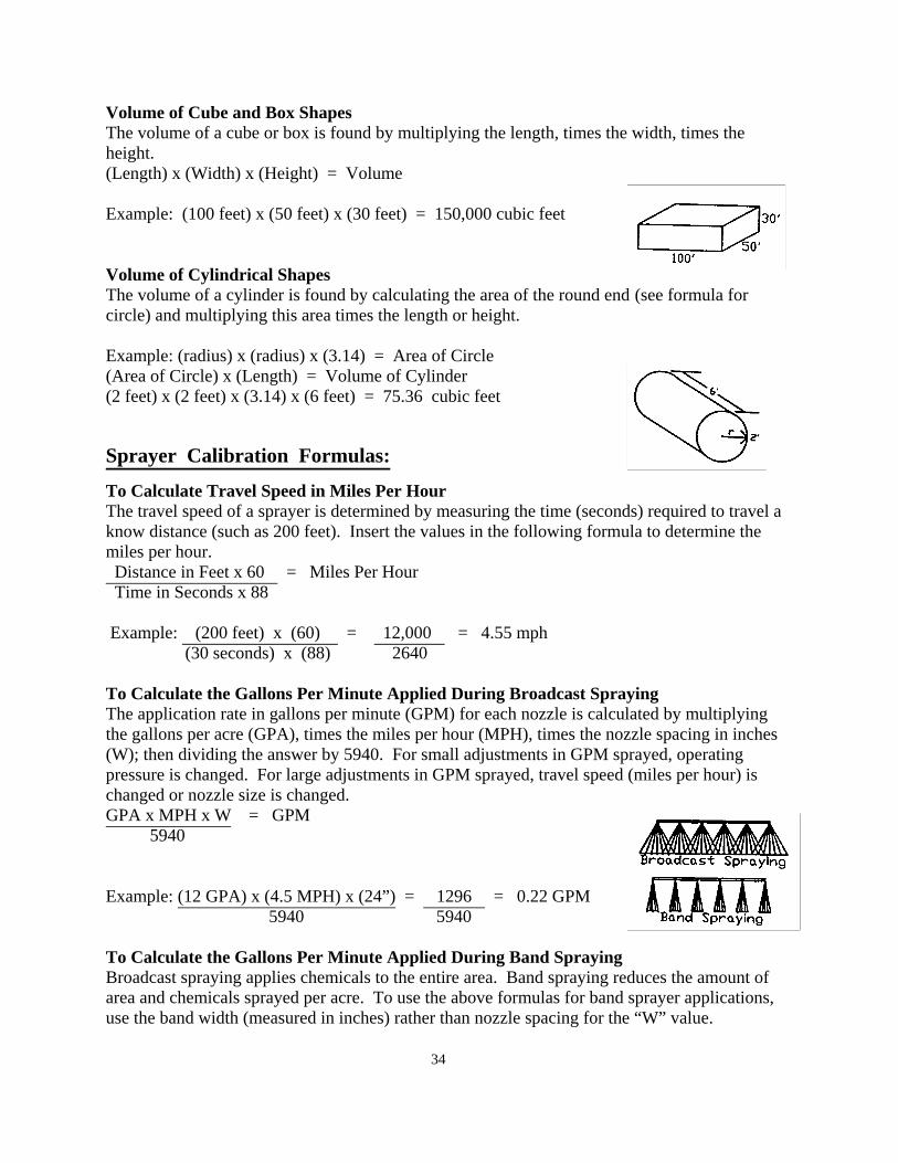
Volume of Cube and Box Shapes The volume of a cube or box is found by multiplying the length, times the width, times the height. (Length) x (Width) x (Height) = Volume Example: (100 feet) x (50 feet) x (30 feet) = 150,000 cubic feet Volume of Cylindrical Shapes The volume of a cylinder is found by calculating the area of the round end (see formula for circle) and multiplying this area times the length or height. Example: (radius) x (radius) x (3.14) = Area of Circle (Area of Circle) x (Length) = Volume of Cylinder (2 feet) x (2 feet) x (3.14) x (6 feet) = 75.36 cubic feet Sprayer Calibration Formulas: To Calculate Travel Speed in Miles Per Hour The travel speed of a sprayer is determined by measuring the time (seconds) required to travel a know distance (such as 200 feet). Insert the values in the following formula to determine the miles per hour. Distance in Feet x 60 = Miles Per Hour Time in Seconds x 88 Example: (200 feet) x (60) = 12,000 = 4.55 mph (30 seconds) x (88) 2640 To Calculate the Gallons Per Minute Applied During Broadcast Spraying The application rate in gallons per minute (GPM) for each nozzle is calculated by multiplying the gallons per acre (GPA), times the miles per hour (MPH), times the nozzle spacing in inches (W); then dividing the answer by 5940. For small adjustments in GPM sprayed, operating pressure is changed. For large adjustments in GPM sprayed, travel speed (miles per hour) is changed or nozzle size is changed. GPA x MPH x W = GPM 5940 Example: (12 GPA) x (4.5 MPH) x (24”) = 1296 = 0.22 GPM 5940 5940 To Calculate the Gallons Per Minute Applied During Band Spraying Broadcast spraying applies chemicals to the entire area. Band spraying reduces the amount of area and chemicals sprayed per acre. To use the above formulas for band sprayer applications, use the band width (measured in inches) rather than nozzle spacing for the “W” value. 34
35
Pesticide Mixing: Terminology The active ingredients of a pesticide are the chemicals in a formulation that control the target pests. The formulation is the pesticide product as sold, usually a mixture of concentrated active ingredients and an inert material. Restricted use pesticides are purchased in formulations requiring dilution prior to application. Formulations are diluted with inert substances such as water. The percentage of active ingredients in a pesticide formulation directly affects dilution and application rates. Given two pesticides, A = 50% active ingredients, B = 100% active ingredients; twice as much pesticide A formulation is required to equal pesticide B formulation. To Determine the Total Amount of Pesticide Formulation Required Per Tank To calculate the total amount of pesticide formulation needed per spray tank, multiply the recommended dilution, ounces/pints/cups/teaspoons/tablespoons/etc. of pesticide per gallon of liquid, times the total number of gallons to be mixed in the sprayer. A full or partial tank of pesticide spray may be mixed. (Dilution Per Gallon) x (Number of Gallons Mixed) = Required Amount of Pesticide Formulation Example: (3 ounces per gallon) x (75 gallons) = 225 ounces Note: 1 gallon = 128 ounces; through unit conversion 225 ounces = 1.76 gallons To Calculate the Amount of Pesticide Formulation Sprayed Per Acre The calculate the total amount of pesticide formulation sprayed per acre is determined by multiplying the quantity of formulation (ounces/pounds/pints/cups/teaspoons/tablespoons/etc.) mixed per gallon of water, times the number of gallons sprayed per acre. (Quantity of Formulation Per Gallon) x (Gallons Sprayed Per Acre) = Formulation Sprayed Per Acre Example: (1/2 pound per gallon) x (12 gallons per acre) = 6 pounds per acre To Calculate the Amount of Active Ingredients Sprayed Per Acre To calculate the total amount of active ingredients (AI) applied per acre, multiply the amount (pounds, gallons, ounces, etc) of pesticide formulation required per acre, times the percentage of active ingredients in the formulation (100%, 75%, 50%, 25%, etc.), and divide the value by 100. (Amount of Formulation Required Per Acre) x (Percentage of AI) = Active Ingredients Per Acre 100 Example: (4 pounds formulation sprayed per acre) x (75% AI) = 3 pounds of AI sprayed per acre 100 Note: 75 % = 0.75 To Calculate the Gallons of Pesticide Mixture Sprayed Per Acre The calculate the total amount of pesticide mixture sprayed per acre is determined by dividing the number of gallons sprayed by the number of acres sprayed. Gallons Sprayed = Gallons Sprayed Per Acre Acres Sprayed Example: 200 Gallons Sprayed = 20 gallons of pesticide mixture sprayed per acre 10 Acres Sprayed