aerodromes - szruibu.comszruibu.com › uploads › 201401 › icao_annex_14_2009.pdf · aerodromes...
TRANSCRIPT

Aerodromes
Annex 14to the Convention onInternational Civil Aviation
This edition incorporates all amendmentsadopted by the Council prior toand supersedes, on November 200 , all previouseditions of Annex 14, Volume I.
For information regarding the applicabilityof Standards and Recommended Practices,
Chapter 1, 1.2 and Foreword.see
5 March 200919 9
International Civil Aviation Organization
International Standards
and Recommended Practices
Fifth EditionJuly 2009
Volume IAerodrome Design and Operations

�������

International Standards and Recommended Practices
This edition incorporates all amendmentsadopted by the Council prior to 5 March 2009 and supersedes, on 19 November 2009, all previous editions of Annex 14, Volume I.
For information regarding the applicability of the Standards and Recommended Practices, see Chapter 1, 1.2 and Foreword.
Fifth Edition July 2009
International Civil Aviation Organization
Aerodromes________________________________
Annex 14 to the Convention on International Civil Aviation
Volume I Aerodrome Design and Operations

Published in separate English, Arabic, Chinese, French, Russian and Spanish editions by the INTERNATIONAL CIVIL AVIATION ORGANIZATION999 University Street, Montréal, Quebec, Canada H3C 5H7
For ordering information and for a complete listing of sales agents and booksellers, please go to the ICAO website at www.icao.int
First edition 1990 Second edition 1995 Third edition 1999 Fourth edition 2004 Fifth edition 2009
Annex 14, Volume I, Aerodrome Design and Operations Order Number: AN14-1 ISBN 978-92-9231-332-6
© ICAO 2009
All rights reserved. No part of this publication may be reproduced, stored in a retrieval system or transmitted in any form or by any means, without prior permission in writing from the International Civil Aviation Organization.

(iii)
AMENDMENTS
Amendments are announced in the supplements to the Catalogue of ICAO Publications; the Catalogue and its supplements are available on the ICAO website at www.icao.int. The space below is provided to keep a record of such amendments.
RECORD OF AMENDMENTS AND CORRIGENDA
AMENDMENTS CORRIGENDA
No.Date
applicableDate
enteredEntered
by No. Date
of issue Date
enteredEntered
by
1–10-A Incorporated in this edition


ANNEX 14 — VOLUME I (v) 19/11/09
TABLE OF CONTENTS
Page
Abbreviations and symbols............................................................................................................................... (x)
Publications ..................................................................................................................................................... (xi)
FOREWORD.................................................................................................................................................... (xiii)
CHAPTER 1. General.................................................................................................................................... 1-1 1.1 Definitions........................................................................................................................................ 1-1 1.2 Applicability .................................................................................................................................... 1-9 1.3 Common reference systems ............................................................................................................. 1-9 1.4 Certification of aerodromes.............................................................................................................. 1-10 1.5 Safety management .......................................................................................................................... 1-10 1.6 Airport design .................................................................................................................................. 1-11 1.7 Reference code................................................................................................................................. 1-11
CHAPTER 2. Aerodrome data ...................................................................................................................... 2-1 2.1 Aeronautical data ............................................................................................................................. 2-1 2.2 Aerodrome reference point .............................................................................................................. 2-2 2.3 Aerodrome and runway elevations................................................................................................... 2-2 2.4 Aerodrome reference temperature.................................................................................................... 2-2 2.5 Aerodrome dimensions and related information .............................................................................. 2-2 2.6 Strength of pavements...................................................................................................................... 2-3 2.7 Pre-flight altimeter check location ................................................................................................... 2-6 2.8 Declared distances............................................................................................................................ 2-6 2.9 Condition of the movement area and related facilities ..................................................................... 2-7 2.10 Disabled aircraft removal................................................................................................................. 2-8 2.11 Rescue and fire fighting ................................................................................................................... 2-8 2.12 Visual approach slope indicator systems.......................................................................................... 2-9 2.13 Coordination between aeronautical information services and aerodrome authorities ...................... 2-9
CHAPTER 3. Physical characteristics ........................................................................................................... 3-1 3.1 Runways........................................................................................................................................... 3-1 3.2 Runway shoulders ............................................................................................................................ 3-7 3.3 Runway turn pads............................................................................................................................. 3-8 3.4 Runway strips................................................................................................................................... 3-10 3.5 Runway end safety areas.................................................................................................................. 3-13 3.6 Clearways......................................................................................................................................... 3-14 3.7 Stopways .......................................................................................................................................... 3-15 3.8 Radio altimeter operating area ......................................................................................................... 3-16 3.9 Taxiways .......................................................................................................................................... 3-16 3.10 Taxiway shoulders ........................................................................................................................... 3-23 3.11 Taxiway strips .................................................................................................................................. 3-23 3.12 Holding bays, runway-holding positions, intermediate holding positions and road-holding positions...................................................................................................................... 3-24

Annex 14 — Aerodromes Volume I
Page
19/11/09 (vi)
3.13 Aprons.............................................................................................................................................. 3-26 3.14 Isolated aircraft parking position...................................................................................................... 3-27 3.15 De-icing/anti-icing facilities............................................................................................................. 3-27
CHAPTER 4. Obstacle restriction and removal ............................................................................................ 4-1 4.1 Obstacle limitation surfaces ............................................................................................................ 4-1 4.2 Obstacle limitation requirements ..................................................................................................... 4-6 4.3 Objects outside the obstacle limitation surfaces............................................................................... 4-12 4.4 Other objects .................................................................................................................................... 4-12
CHAPTER 5. Visual aids for navigation ....................................................................................................... 5-1 5.1 Indicators and signalling devices ..................................................................................................... 5-1 5.1.1 Wind direction indicator .................................................................................................... 5-1 5.1.2 Landing direction indicator................................................................................................ 5-1 5.1.3 Signalling lamp.................................................................................................................. 5-2 5.1.4 Signal panels and signal area ............................................................................................. 5-3 5.2 Markings .......................................................................................................................................... 5-3 5.2.1 General............................................................................................................................... 5-3 5.2.2 Runway designation marking ............................................................................................ 5-4 5.2.3 Runway centre line marking .............................................................................................. 5-6 5.2.4 Threshold marking............................................................................................................. 5-6 5.2.5 Aiming point marking........................................................................................................ 5-9 5.2.6 Touchdown zone marking ................................................................................................. 5-10 5.2.7 Runway side stripe marking............................................................................................... 5-11 5.2.8 Taxiway centre line marking ............................................................................................. 5-13 5.2.9 Runway turn pad marking.................................................................................................. 5-15 5.2.10 Runway-holding position marking .................................................................................... 5-16 5.2.11 Intermediate holding position marking .............................................................................. 5-17 5.2.12 VOR aerodrome checkpoint marking ................................................................................ 5-18 5.2.13 Aircraft stand marking ....................................................................................................... 5-18 5.2.14 Apron safety lines .............................................................................................................. 5-20 5.2.15 Road-holding position marking ......................................................................................... 5-21 5.2.16 Mandatory instruction marking.......................................................................................... 5-21 5.2.17 Information marking .......................................................................................................... 5-22 5.3 Lights ............................................................................................................................................... 5-23 5.3.1 General............................................................................................................................... 5-23 5.3.2 Emergency lighting............................................................................................................ 5-28 5.3.3 Aeronautical beacons......................................................................................................... 5-28 5.3.4 Approach lighting systems................................................................................................. 5-30 5.3.5 Visual approach slope indicator systems ........................................................................... 5-37 5.3.6 Circling guidance lights ..................................................................................................... 5-48 5.3.7 Runway lead-in lighting systems ....................................................................................... 5-49 5.3.8 Runway threshold identification lights .............................................................................. 5-50 5.3.9 Runway edge lights............................................................................................................ 5-50 5.3.10 Runway threshold and wing bar lights............................................................................... 5-51 5.3.11 Runway end lights ............................................................................................................. 5-54 5.3.12 Runway centre line lights .................................................................................................. 5-54 5.3.13 Runway touchdown zone lights ......................................................................................... 5-55 5.3.14 Rapid exit taxiway indicator lights .................................................................................... 5-57 5.3.15 Stopway lights ................................................................................................................... 5-58 5.3.16 Taxiway centre line lights.................................................................................................. 5-59

Chapter 1 Annex 14 — Aerodromes
Page
(vii) 19/11/09
5.3.17 Taxiway edge lights ........................................................................................................... 5-63 5.3.18 Runway turn pad lights ...................................................................................................... 5-64 5.3.19 Stop bars ............................................................................................................................ 5-65 5.3.20 Intermediate holding position lights .................................................................................. 5-67 5.3.21 De-icing/anti-icing facility exit lights ................................................................................ 5-67 5.3.22 Runway guard lights .......................................................................................................... 5-67 5.3.23 Apron floodlighting ........................................................................................................... 5-70 5.3.24 Visual docking guidance system........................................................................................ 5-71 5.3.25 Advanced visual docking guidance system ....................................................................... 5-73 5.3.26 Aircraft stand manoeuvring guidance lights ...................................................................... 5-75 5.3.27 Road-holding position light ............................................................................................... 5-76 5.4 Signs................................................................................................................................................. 5-76 5.4.1 General............................................................................................................................... 5-76 5.4.2 Mandatory instruction signs............................................................................................... 5-80 5.4.3 Information signs ............................................................................................................... 5-83 5.4.4 VOR aerodrome checkpoint sign....................................................................................... 5-85 5.4.5 Aerodrome identification sign ........................................................................................... 5-86 5.4.6 Aircraft stand identification signs...................................................................................... 5-87 5.4.7 Road-holding position sign................................................................................................ 5-87 5.5 Markers ............................................................................................................................................ 5-88 5.5.1 General............................................................................................................................... 5-88 5.5.2 Unpaved runway edge markers.......................................................................................... 5-88 5.5.3 Stopway edge markers ....................................................................................................... 5-89 5.5.4 Edge markers for snow-covered runways.......................................................................... 5-89 5.5.5 Taxiway edge markers ....................................................................................................... 5-89 5.5.6 Taxiway centre line markers.............................................................................................. 5-90 5.5.7 Unpaved taxiway edge markers ......................................................................................... 5-90 5.5.8 Boundary markers.............................................................................................................. 5-91
CHAPTER 6. Visual aids for denoting obstacles .......................................................................................... 6-1 6.1 Objects to be marked and/or lighted ................................................................................................ 6-1 6.2 Marking of objects ........................................................................................................................... 6-2 6.3 Lighting of objects ........................................................................................................................... 6-6 6.4 Wind turbines................................................................................................................................... 6-11
CHAPTER 7. Visual aids for denoting restricted use areas........................................................................... 7-1 7.1 Closed runways and taxiways, or parts thereof ................................................................................ 7-1 7.2 Non-load-bearing surfaces ............................................................................................................... 7-2 7.3 Pre-threshold area ............................................................................................................................ 7-3 7.4 Unserviceable areas.......................................................................................................................... 7-4
CHAPTER 8. Electrical systems ................................................................................................................... 8-1 8.1 Electrical power supply systems for air navigation facilities ........................................................... 8-1 8.2 System design .................................................................................................................................. 8-2 8.3 Monitoring ....................................................................................................................................... 8-4
CHAPTER 9. Aerodrome operational services, equipment and installations................................................ 9-1 9.1 Aerodrome emergency planning ...................................................................................................... 9-1 9.2 Rescue and fire fighting ................................................................................................................... 9-3 9.3 Disabled aircraft removal................................................................................................................. 9-9 9.4 Wildlife strike hazard reduction....................................................................................................... 9-10

Annex 14 — Aerodromes Volume I
Page
19/11/09 (viii)
9.5 Apron management service.............................................................................................................. 9-10 9.6 Ground servicing of aircraft ............................................................................................................. 9-11 9.7 Aerodrome vehicle operations ......................................................................................................... 9-11 9.8 Surface movement guidance and control systems............................................................................ 9-12 9.9 Siting of equipment and installations on operational areas .............................................................. 9-13 9.10 Fencing............................................................................................................................................. 9-15 9.11 Security lighting............................................................................................................................... 9-15
CHAPTER 10. Aerodrome maintenance ....................................................................................................... 10-1 10.1 General............................................................................................................................................. 10-1 10.2 Pavements ........................................................................................................................................ 10-1 10.3 Runway pavement overlays ............................................................................................................. 10-3 10.4 Visual aids........................................................................................................................................ 10-3
APPENDIX 1. Colours for aeronautical ground lights, markings, signs and panels ..................................... APP 1-1 1. General............................................................................................................................................. APP 1-1 2. Colours for aeronautical ground lights............................................................................................. APP 1-1 3. Colours for markings, signs and panels ........................................................................................... APP 1-3
APPENDIX 2. Aeronautical ground light characteristics.............................................................................. APP 2-1
APPENDIX 3. Mandatory instruction markings and information markings ................................................. APP 3-1
APPENDIX 4. Requirements concerning design of taxiing guidance signs.................................................. APP 4-1
APPENDIX 5. Aeronautical data quality requirements................................................................................. APP 5-1
APPENDIX 6. Location of lights on obstacles.............................................................................................. APP 6-1
ATTACHMENT A. Guidance material supplementary to Annex 14, Volume I........................................... ATT A-1 1. Number, siting and orientation of runways ...................................................................................... ATT A-1 2. Clearways and stopways .................................................................................................................. ATT A-2 3. Calculation of declared distances..................................................................................................... ATT A-3 4. Slopes on a runway .......................................................................................................................... ATT A-4 5. Runway surface evenness ................................................................................................................ ATT A-6 6. Determining and expressing the friction characteristics of snow- and ice-covered paved surfaces .................................................................................................................................. ATT A-7 7. Determination of friction characteristics of wet paved runways...................................................... ATT A-9 8. Strips ................................................................................................................................................ ATT A-11 9. Runway end safety areas.................................................................................................................. ATT A-12 10. Location of threshold ....................................................................................................................... ATT A-13 11. Approach lighting systems............................................................................................................... ATT A-14 12. Priority of installation of visual approach slope indicator systems .................................................. ATT A-21 13. Lighting of unserviceable areas ....................................................................................................... ATT A-22 14. Rapid exit taxiway indicator lights................................................................................................... ATT A-22 15. Intensity control of approach and runway lights .............................................................................. ATT A-22 16. Signal area........................................................................................................................................ ATT A-22 17. Rescue and fire fighting services ..................................................................................................... ATT A-23 18. Operators of vehicles ....................................................................................................................... ATT A-25 19. The ACN-PCN method of reporting pavement strength.................................................................. ATT A-26

Chapter 1 Annex 14 — Aerodromes
Page
(ix) 19/11/09
ATTACHMENT B. Obstacle limitation surfaces.......................................................................................... ATT B-1
LIMITED INDEX OF SIGNIFICANT SUBJECTS INCLUDED IN ANNEX 14, VOLUME I ..................... 1

Annex 14 — Aerodromes Volume I
19/11/09 (x)
ABBREVIATIONS AND SYMBOLS (used in Annex 14, Volume I)
Abbreviations Abbreviations
ACN Aircraft classification number aprx Approximately ASDA Accelerate-stop distance available ATS Air traffic services C Degree Celsius CBR California bearing ratio cd Candela CIE Commission Internationale de l’Éclairage cm Centimetre DME Distance measuring equipment ft Foot ILS Instrument landing system IMC Instrument meteorological conditions K Degree Kelvin kg Kilogram km Kilometre km/h Kilometre per hour kt Knot L Litre LDA Landing distance available m Metre max Maximum mm Millimetre mnm Minimum MN Meganewton
MPa Megapascal NM Nautical mile NU Not usable OCA/H Obstacle clearance altitude/height OFZ Obstacle free zone PCN Pavement classification number RESA Runway end safety area RVR Runway visual range TODA Take-off distance available TORA Take-off run available VMC Visual meteorological conditions VOR Very high frequency omnidirectional radio
range
Symbols
° Degree = Equals � Minute of arc � Friction coefficient > Greater than < Less than % Percentage ± Plus or minus

Publications Annex 14 — Aerodromes
(xi) 19/11/09
PUBLICATIONS(related to the specifications of this Annex)
Advanced Surface Movement Guidance and Control Systems (A-SMGCS) Manual (Doc 9830)
Aerodrome Design Manual (Doc 9157) Part 1 — Runways Part 2 — Taxiways, Aprons and Holding Bays Part 3 — Pavements Part 4 — Visual Aids Part 5 — Electrical Systems Part 6 — Frangibility
Aeronautical Information Services Manual (Doc 8126)
Aircraft Type Designators (Doc 8643)
Airport Planning Manual (Doc 9184) Part 1 — Master Planning Part 2 — Land Use and Environmental Control Part 3 — Guidelines for Consultant/Construction Services
Airport Services Manual (Doc 9137) Part 1 — Rescue and Fire Fighting Part 2 — Pavement Surface Conditions Part 3 — Bird Control and Reduction Part 5 — Removal of Disabled Aircraft Part 6 — Control of Obstacles Part 7 — Airport Emergency Planning Part 8 — Airport Operational Services Part 9 — Airport Maintenance Practices
Air Traffic Services Planning Manual (Doc 9426)
Airworthiness Manual (Doc 9760) Volume I — Organization and Procedures Volume II — Design Certification and Continuing Airworthiness
Guidance on the Balanced Approach to Aircraft Noise Management (Doc 9829)
Heliport Manual (Doc 9261)
Human Factors Training Manual (Doc 9683)
Manual of Aircraft Ground De-icing/Anti-icing Operations (Doc 9640)
Manual of Surface Movement Guidance and Control Systems (SMGCS) (Doc 9476)
Manual on Certification of Aerodromes (Doc 9774)
Manual on Laser Emitters and Flight Safety (Doc 9815)

Annex 14 — Aerodromes Volume I
19/11/09 (xii)
Manual on Simultaneous Operations on Parallel or Near-Parallel Instrument Runways (SOIR) (Doc 9643)
Manual on the ICAO Bird Strike Information System (IBIS) (Doc 9332)
Procedures for Air Navigation Services — Aircraft Operations (PANS-OPS) (Doc 8168) Volume I — Flight Procedures Volume II — Construction of Visual and Instrument Flight Procedures
Procedures for Air Navigation Services — Air Traffic Management (PANS-ATM) (Doc 4444)
Safety Management Manual (SMM) (Doc 9859)
Stolport Manual (Doc 9150)
World Geodetic System — 1984 (WGS-84) Manual (Doc 9674)
_____________________

ANNEX 14 — VOLUME I (xiii) 19/11/09
FOREWORD
Historical background
Standards and Recommended Practices for Aerodromes were first adopted by the Council on 29 May 1951 pursuant to the provisions of Article 37 of the Convention on International Civil Aviation (Chicago 1944) and designated as Annex 14 to the Convention. The Standards and Recommended Practices were based on recommendations of the Aerodromes, Air Routes and Ground Aids Division at its third session in September 1947 and at its fourth session in November 1949.
Table A shows the origin of subsequent amendments together with a list of the principal subjects involved and the dates on which the Annex and the amendments were adopted by the Council, when they became effective and when they became applicable.
Action by Contracting States
Notification of differences. The attention of Contracting States is drawn to the obligation imposed by Article 38 of the Convention by which Contracting States are required to notify the Organization of any differences between their national regulations and practices and the International Standards contained in this Annex and any amendments thereto. Contracting States are invited to extend such notification to any differences from the Recommended Practices contained in this Annex and any amendments thereto, when the notification of such differences is important for the safety of air navigation. Further, Contracting States are invited to keep the Organization currently informed of any differences which may subsequently occur, or of the withdrawal of any differences previously notified. A specified request for notification of differences will be sent to Contracting States immediately after the adoption of each amendment to this Annex.
The attention of States is also drawn to the provisions of Annex 15 related to the publication of differences between their national regulations and practices and the related ICAO Standards and Recommended Practices through the Aeronautical Information Service, in addition to the obligation of States under Article 38 of the Convention.
Promulgation of information. The establishment and withdrawal of and changes to facilities, services and procedures affecting aircraft operations provided in accordance with the Standards and Recommended Practices specified in this Annex should be notified and take effect in accordance with the provisions of Annex 15.
Status of Annex components
An Annex is made up of the following component parts, not all of which, however, are necessarily found in every Annex; they have the status indicated:
1.— Material comprising the Annex proper:
a) Standards and Recommended Practices adopted by the Council under the provisions of the Convention. They are defined as follows:
Standard: Any specification for physical characteristics, configuration, matériel, performance, personnel or procedure, the uniform application of which is recognized as necessary for the safety or regularity of international

Annex 14 — Aerodromes Volume I
19/11/09 (xiv)
air navigation and to which Contracting States will conform in accordance with the Convention; in the event of impossibility of compliance, notification to the Council is compulsory under Article 38.
Recommended Practice: Any specification for physical characteristics, configuration, matériel, performance, personnel or procedure, the uniform application of which is recognized as desirable in the interest of safety, regularity or efficiency of international air navigation, and to which Contracting States will endeavour to conform in accordance with the Convention.
b) Appendices comprising material grouped separately for convenience but forming part of the Standards and Recommended Practices adopted by the Council.
c) Definitions of terms used in the Standards and Recommended Practices which are not self-explanatory in that they do not have accepted dictionary meanings. A definition does not have independent status but is an essential part of each Standard and Recommended Practice in which the term is used, since a change in the meaning of the term would affect the specification.
d) Tables and Figures which add to or illustrate a Standard or Recommended Practice and which are referred to therein, form part of the associated Standard or Recommended Practice and have the same status.
2.— Material approved by the Council for publication in association with the Standards and Recommended Practices:
a) Forewords comprising historical and explanatory material based on the action of the Council and including an explanation of the obligations of States with regard to the application of the Standards and Recommended Practices ensuing from the Convention and the Resolution of Adoption.
b) Introductions comprising explanatory material introduced at the beginning of parts, chapters or sections of the Annex to assist in the understanding of the application of the text.
c) Notes included in the text, where appropriate, to give factual information or references bearing on the Standards or Recommended Practices in question, but not constituting part of the Standards or Recommended Practices.
d) Attachments comprising material supplementary to the Standards and Recommended Practices, or included as a guide to their application.
Selection of language
This Annex has been adopted in six languages — English, Arabic, Chinese, French, Russian and Spanish. Each Contracting State is requested to select one of those texts for the purpose of national implementation and for other effects provided for in the Convention, either through direct use or through translation into its own national language, and to notify the Organization accordingly.
Editorial practices
The following practice has been adhered to in order to indicate at a glance the status of each statement: Standards have been printed in light face roman; Recommended Practices have been printed in light face italics, the status being indicated by the prefix Recommendation; Notes have been printed in light face italics, the status being indicated by the prefix Note.
The following editorial practice has been followed in the writing of specifications: for Standards the operative verb “shall” is used, and for Recommended Practices the operative verb “should” is used.

Foreword Annex 14 — Aerodromes
(xv) 19/11/09
The units of measurement used in this document are in accordance with the International System of Units (SI) as specified in Annex 5 to the Convention on International Civil Aviation. Where Annex 5 permits the use of non-SI alternative units these are shown in parentheses following the basic units. Where two sets of units are quoted it must not be assumed that the pairs ofvalues are equal and interchangeable. It may, however, be inferred that an equivalent level of safety is achieved when either set of units is used exclusively.
Any reference to a portion of this document, which is identified by a number and/or title, includes all subdivisions of that portion.
Table A. Amendments to Annex 14, Volume I
Amendment Source(s) Subject(s)
Adopted/ApprovedEffective
Applicable
1st Edition Third and Fourth Sessions of the Aerodromes, Air Routes and Ground Aids Division
— 29 May 1951 11 November 1951 11 June 1952* 11 June 1954
1 to 6 Fifth Session of the Aerodromes, Air Routes and Ground Aids Division
Physical characteristics of runways, strips, clearways, stopways, taxiways and aprons; physical characteristics of channels, turning basins, taxi channels and mooring areas; approach areas; clearing and restriction of obstructions; obstruction marking; marking of unserviceable portions of the movement area; secondary power supply; aerodrome beacon; runway markings; stopway markers; approach, lead-in and runway lighting.
20 May 1953 11 September 1953 11 April 1954* 11 January 1955
7 to 13 Sixth Session of the Aerodromes, Air Routes and Ground Aids Division
Physical characteristics of runways, strips, taxiways and aprons; approach and take-off areas and surfaces; clearing and restriction of obstructions; obstruction markings; runway markings; stopway markers; taxiway markings; approach, runway and taxiway lighting; circling guidance lights; rescue and fire fighting services.
12 May 1958 11 September 1958 11 December 1958
14 Correspondence Precision approach lighting system. 17 May 1959 11 October 1959 11 October 1959
15 Vertical Separation Panel
Pre-flight altimeter checkpoint. 15 May 1959 11 October 1959 11 October 1959
16 Correspondence Extinguishing agents. 12 December 1960 12 December 1960 12 December 1960
17 Correspondence Pre-flight altimeter checkpoint. 12 December 1960 12 December 1960 12 December 1960
18 First Meeting of the ANC Visual Aids Panel
VASIS 19 June 1961 11 October 1961 11 October 1961
* Two applicability dates approved.

Annex 14 — Aerodromes Volume I
19/11/09 (xvi)
Amendment Source(s) Subject(s)
Adopted/ApprovedEffective
Applicable
19 Seventh Session of theAerodromes, Air Routes and Ground Aids Division
Physical characteristics of runways, clearways, stopways, taxiways and aprons; take-off and approach areas; clearing and restriction of obstructions; obstruction markings; wind direction indicator; landing direction indicator; aerodrome beacon; runway markings; approach lighting system; runway alignment indicator; runway centre line; touchdown zone and taxiway lighting; rescue and fire fighting services.
23 March 1964 11 August 1964 11 November 1964
20 Second Meeting of theANC Visual Aids Panel
Visual aids for use in operational performance category II conditions. 13 December 1965 13 April 1966 25 August 1966
21 Fourth Air Navigation Conference and Fourth Meeting of the ANC Visual Aids Panel
Emergency lighting; threshold marking; fixed distance marking; approach light beacons; taxiway centre line lighting; secondary power supply; maintenance of aerodrome lighting and marking aids; monitoring of visual aids.
28 June 1967 28 October 1967 18 February 1968
22 Correspondence and ANC Visual Aids Panel
VOR aerodrome checkpoint marking and sign. 28 June 1968 28 October 1968 18 September 1969
23 Fifth Air Navigation Conference
Declared distances; strength of pavements; information on aerodrome conditions; reference code letters; runway length correction for slope; runway strips; taxiway clearances; holding bays; taxi-holding position markings; approach lighting systems; visual approach slope indicator systems; secondary power supply; rescue and fire fighting services; bird hazard reduction services.
23 January 1969 23 May 1969 18 September 1969
24 Fifth Meeting of the ANC Visual Aids Panel and First Meeting of the ANC Rescue and Fire Fighting Panel
Marking of unusable or unserviceable portions of the movement area; touchdown zone markings; category II holding position marking and sign; T-VASIS and AT-VASIS; runway edge lighting; exit taxiway centre line lighting; stop bars and clearance bars; emergency access roads; colour specifications for lights.
31 March 1971 16 September 1971 16 January 1972
25 ANC Visual Aids Panel
Visual approach slope guidance for long-bodied aircraft. 26 May 1971 26 September 1971 16 January 1972
26 Seventeenth Session of the Assembly and Middle East/South East Asia Regional Air Navigation Meeting
Aerodrome security; water rescue vehicles. 15 December 1971 15 April 1972 17 December 1972
27 ANC Visual Aids Panel and Middle East/South East Asia Regional Air Navigation Meeting
Runway centre line light colour coding; maintenance services. 20 March 1972 20 July 1972 17 December 1972
28 Secretariat and Sixth Meeting of the ANC Visual Aids Panel
Definition for snow on the ground; frangibility of light fixtures; runway centre line marking; taxiway centre line lighting; colour specifications for lights.
11 December 1972 11 April 1973 16 August 1973
29 Council action in pursuance of Assembly Resolutions A17-10 and A18-10
Aerodrome security. 17 December 1973 17 April 1974 23 May 1974

Foreword Annex 14 — Aerodromes
(xvii) 19/11/09
Amendment Source(s) Subject(s)
Adopted/ApprovedEffective
Applicable
30 Eighth Air Navigation Conference and editorial revision of the Annex
Runway shoulders and strips; runway end safety areas; aerodrome reference temperature; clearways; holding bays; physical characteristics of taxiways; taxiway shoulders and strips; pavement strength; runway transverse slopes; runway braking action; obstacle limitation surfaces; category III runway lighting and marking; taxiway lighting; stop bars; rescue and fire fighting services; disabled aircraft removal.
13 February 1976 13 June 1976 30 December 1976
31 Seventh Meeting of the ANC Visual Aids Panel and Fifth Meeting of the ANC Obstacle Clearance Panel
Obstacle limitation surfaces; light intensity control; inset light temperatures; taxiway centre line lights; apron floodlighting; visual docking guidance systems; signs; maintenance of visual aids.
13 December 1976 13 April 1977 16 October 1977
32 Correspondence and ANC Visual Aids Panel
Definition of frangibility; siting and construction of equipment and installations on operational areas; colour specifications for lights and markings.
14 December 1977 14 April 1978 10 August 1978
33 Correspondence and Secretariat
Reporting of information on visual approach slope indicator systems; runway, taxiway and taxi-holding position markings; approach lighting for displaced thresholds; runway edge and centre line lights; aerodrome emergency planning.
26 March 1979 26 July 1979 29 November 1979
34 Eighth Meeting of the ANC Visual Aids Panel
Apron markings; precision approach lighting systems; visual approach slope indicator systems; circling guidance lights; runway lead-in lighting systems; stop bars; visual docking guidance system; aircraft stand manoeuvring guidance lights; aircraft stand identification signs; marking and lighting of obstacles.
30 November 1979 30 March 1980 27 November 1980
35 Secretariat and the ANC Visual Aids Panel
Reporting of pavement strength; visual approach slope indicator systems; approach lighting systems; maintenance of lighting.
23 March 1981 23 July 1981 26 November 1981
36 Aerodromes, Air Routes and Ground Aids Divisional Meeting (1981), NinthMeeting of the ANC Visual Aids Panel and Secretariat
Aerodrome reference code; runway friction characteristics; runway end safety areas; taxiway separation distances; rapid exit taxiways; taxiways on bridges; holding bays; obstacle limitation surfaces; PAPI; taxi-holding position marking and lights; runway centre line guidance; visual ground signals; rescue and fire fighting; apron management service; declared distances; ground servicing of aircraft; units of measure.
22 November 1982 23 March 1983 24 November 1983
37 Secretariat Fuelling. 29 March 1983 29 July 1983 24 November 1983
38 Secretariat and the ANC Visual Aids Panel
Aerodrome data; APAPI; colour coding of exit taxiway centre line lights; stop bars; taxi-holding position lights; taxiway edge markers; markers for overhead wires; obstacle lighting of lighthouses; maintenance of taxiway centre line lights; surface marking colours.
17 March 1986 27 July 1986 20 November 1986
Annex 14 — Aerodromes Volume I
19/11/09 (xviii)
Amendment Source(s) Subject(s)
Adopted/ApprovedEffective
Applicable
39(Annex 14, Volume I,
1st Edition)
Secretariat and the ANC Visual Aids Panel
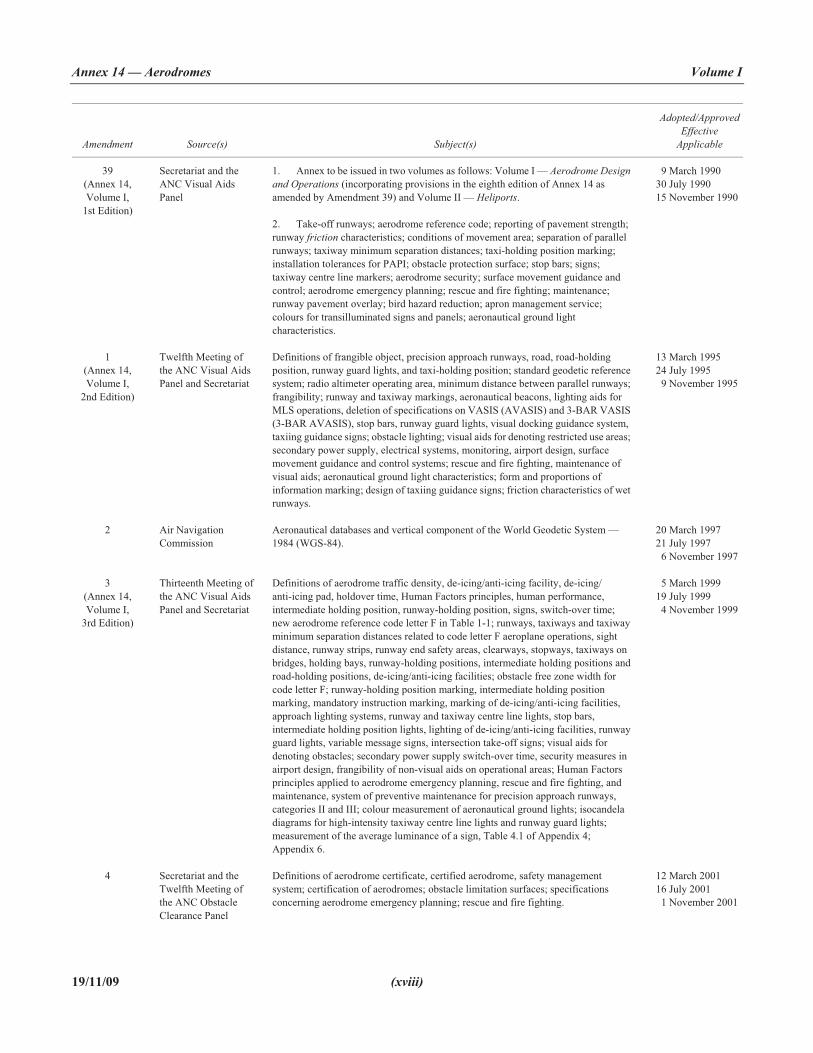
1. Annex to be issued in two volumes as follows: Volume I — Aerodrome Design and Operations (incorporating provisions in the eighth edition of Annex 14 as amended by Amendment 39) and Volume II — Heliports.
2. Take-off runways; aerodrome reference code; reporting of pavement strength; runway friction characteristics; conditions of movement area; separation of parallel runways; taxiway minimum separation distances; taxi-holding position marking; installation tolerances for PAPI; obstacle protection surface; stop bars; signs; taxiway centre line markers; aerodrome security; surface movement guidance and control; aerodrome emergency planning; rescue and fire fighting; maintenance; runway pavement overlay; bird hazard reduction; apron management service; colours for transilluminated signs and panels; aeronautical ground light characteristics.
19 March 1990 30 July 1990 15 November 1990
1(Annex 14, Volume I,
2nd Edition)
Twelfth Meeting of the ANC Visual Aids Panel and Secretariat
Definitions of frangible object, precision approach runways, road, road-holding position, runway guard lights, and taxi-holding position; standard geodetic reference system; radio altimeter operating area, minimum distance between parallel runways; frangibility; runway and taxiway markings, aeronautical beacons, lighting aids for MLS operations, deletion of specifications on VASIS (AVASIS) and 3-BAR VASIS (3-BAR AVASIS), stop bars, runway guard lights, visual docking guidance system, taxiing guidance signs; obstacle lighting; visual aids for denoting restricted use areas; secondary power supply, electrical systems, monitoring, airport design, surface movement guidance and control systems; rescue and fire fighting, maintenance of visual aids; aeronautical ground light characteristics; form and proportions of information marking; design of taxiing guidance signs; friction characteristics of wet runways.
13 March 1995 24 July 1995 19 November 1995
2 Air Navigation Commission
Aeronautical databases and vertical component of the World Geodetic System — 1984 (WGS-84).
20 March 1997 21 July 1997 16 November 1997
3(Annex 14, Volume I,
3rd Edition)
Thirteenth Meeting of the ANC Visual Aids Panel and Secretariat
Definitions of aerodrome traffic density, de-icing/anti-icing facility, de-icing/ anti-icing pad, holdover time, Human Factors principles, human performance, intermediate holding position, runway-holding position, signs, switch-over time; new aerodrome reference code letter F in Table 1-1; runways, taxiways and taxiway minimum separation distances related to code letter F aeroplane operations, sight distance, runway strips, runway end safety areas, clearways, stopways, taxiways on bridges, holding bays, runway-holding positions, intermediate holding positions and road-holding positions, de-icing/anti-icing facilities; obstacle free zone width for code letter F; runway-holding position marking, intermediate holding position marking, mandatory instruction marking, marking of de-icing/anti-icing facilities, approach lighting systems, runway and taxiway centre line lights, stop bars, intermediate holding position lights, lighting of de-icing/anti-icing facilities, runway guard lights, variable message signs, intersection take-off signs; visual aids for denoting obstacles; secondary power supply switch-over time, security measures in airport design, frangibility of non-visual aids on operational areas; Human Factors principles applied to aerodrome emergency planning, rescue and fire fighting, and maintenance, system of preventive maintenance for precision approach runways, categories II and III; colour measurement of aeronautical ground lights; isocandela diagrams for high-intensity taxiway centre line lights and runway guard lights; measurement of the average luminance of a sign, Table 4.1 of Appendix 4; Appendix 6.
15 March 1999 19 July 1999 14 November 1999
4 Secretariat and the Twelfth Meeting of the ANC Obstacle Clearance Panel
Definitions of aerodrome certificate, certified aerodrome, safety management system; certification of aerodromes; obstacle limitation surfaces; specifications concerning aerodrome emergency planning; rescue and fire fighting.
12 March 2001 16 July 2001 11 November 2001
Foreword Annex 14 — Aerodromes
(xix) 19/11/09
Amendment Source(s) Subject(s)
Adopted/ApprovedEffective
Applicable
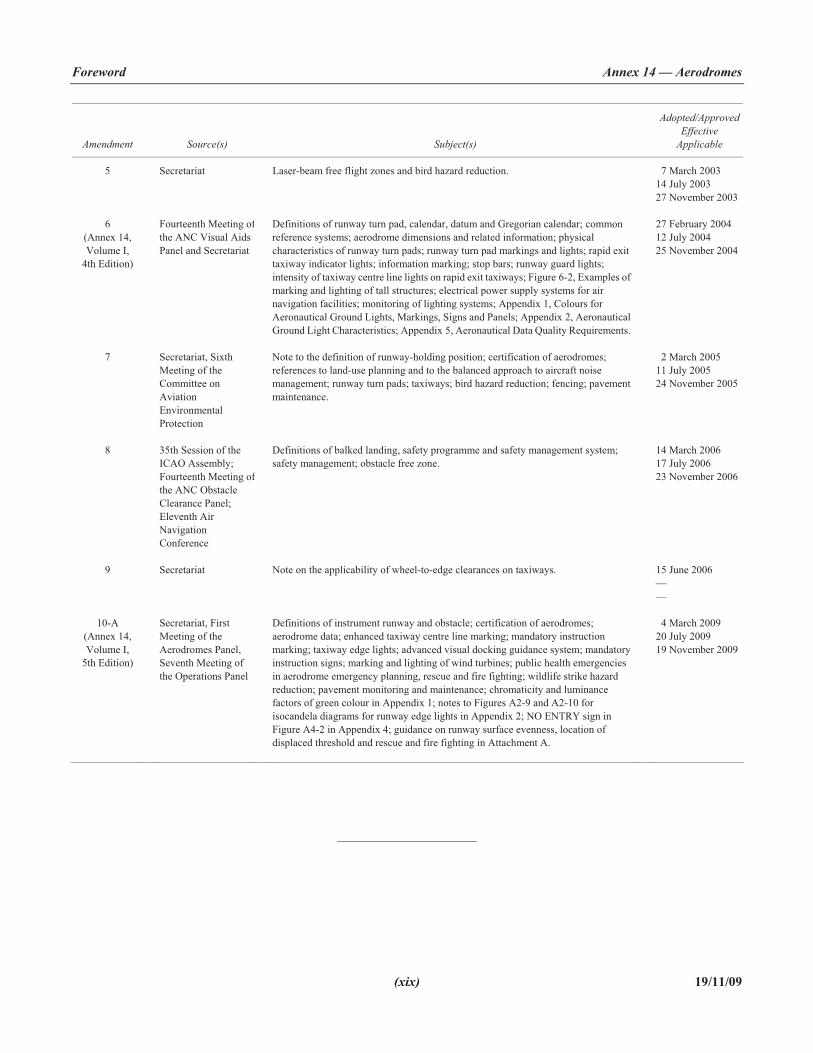
5 Secretariat Laser-beam free flight zones and bird hazard reduction. 17 March 2003 14 July 2003 27 November 2003
6(Annex 14, Volume I,
4th Edition)
Fourteenth Meeting ofthe ANC Visual Aids Panel and Secretariat
Definitions of runway turn pad, calendar, datum and Gregorian calendar; common reference systems; aerodrome dimensions and related information; physical characteristics of runway turn pads; runway turn pad markings and lights; rapid exit taxiway indicator lights; information marking; stop bars; runway guard lights; intensity of taxiway centre line lights on rapid exit taxiways; Figure 6-2, Examples of marking and lighting of tall structures; electrical power supply systems for air navigation facilities; monitoring of lighting systems; Appendix 1, Colours for Aeronautical Ground Lights, Markings, Signs and Panels; Appendix 2, Aeronautical Ground Light Characteristics; Appendix 5, Aeronautical Data Quality Requirements.
27 February 2004 12 July 2004 25 November 2004
7 Secretariat, Sixth Meeting of the Committee on AviationEnvironmental Protection
Note to the definition of runway-holding position; certification of aerodromes; references to land-use planning and to the balanced approach to aircraft noise management; runway turn pads; taxiways; bird hazard reduction; fencing; pavement maintenance.
12 March 2005 11 July 2005 24 November 2005
8 35th Session of the ICAO Assembly; Fourteenth Meeting ofthe ANC Obstacle Clearance Panel; Eleventh Air NavigationConference
Definitions of balked landing, safety programme and safety management system; safety management; obstacle free zone.
14 March 2006 17 July 2006 23 November 2006
9 Secretariat Note on the applicability of wheel-to-edge clearances on taxiways. 15 June 2006 ——
10-A (Annex 14, Volume I,
5th Edition)
Secretariat, First Meeting of the Aerodromes Panel, Seventh Meeting of the Operations Panel
Definitions of instrument runway and obstacle; certification of aerodromes; aerodrome data; enhanced taxiway centre line marking; mandatory instruction marking; taxiway edge lights; advanced visual docking guidance system; mandatory instruction signs; marking and lighting of wind turbines; public health emergencies in aerodrome emergency planning, rescue and fire fighting; wildlife strike hazard reduction; pavement monitoring and maintenance; chromaticity and luminance factors of green colour in Appendix 1; notes to Figures A2-9 and A2-10 for isocandela diagrams for runway edge lights in Appendix 2; NO ENTRY sign in Figure A4-2 in Appendix 4; guidance on runway surface evenness, location of displaced threshold and rescue and fire fighting in Attachment A.
14 March 2009 20 July 2009 19 November 2009
_____________________


ANNEX 14 — VOLUME I 1-1 19/11/09
INTERNATIONAL STANDARDS AND RECOMMENDED PRACTICES
CHAPTER 1. GENERAL
Introductory Note.— This Annex contains Standards and Recommended Practices (specifications) that prescribe the physical characteristics and obstacle limitation surfaces to be provided for at aerodromes, and certain facilities and technicalservices normally provided at an aerodrome. It also contains specifications dealing with obstacles outside those limitation surfaces. It is not intended that these specifications limit or regulate the operation of an aircraft.
To a great extent, the specifications for individual facilities detailed in Annex 14, Volume I, have been interrelated by a reference code system, described in this chapter, and by the designation of the type of runway for which they are to be provided, as specified in the definitions. This not only simplifies the reading of Volume I of this Annex, but in most cases, provides forefficiently proportioned aerodromes when the specifications are followed.
This document sets forth the minimum aerodrome specifications for aircraft which have the characteristics of those which are currently operating or for similar aircraft that are planned for introduction. Accordingly, any additional safeguards that might be considered appropriate to provide for more demanding aircraft are not taken into account. Such matters are left to appropriate authorities to evaluate and take into account as necessary for each particular aerodrome. Guidance on some possible effects of future aircraft on these specifications is given in the Aerodrome Design Manual (Doc 9157), Part 2.
It is to be noted that the specifications for precision approach runway categories II and III are only applicable to runways intended to be used by aeroplanes in code numbers 3 and 4.
Annex 14, Volume I, does not include specifications relating to the overall planning of aerodromes (such as separation between adjacent aerodromes or capacity of individual aerodromes), impact on the environment, or to economic and other non-technical factors that need to be considered in the development of an aerodrome. Information on these subjects is included in the Airport Planning Manual (Doc 9184), Part 1. Guidance material on the environmental aspects of the development and operation of an aerodrome is included in the Airport Planning Manual (Doc 9184), Part 2.
Aviation security is an integral part of aerodrome planning and operations. Annex 14, Volume I, contains several specifications aimed at enhancing the level of security at aerodromes. Specifications on other facilities related to security are given in Annex 17 and detailed guidance on the subject is contained in the ICAO Security Manual.
1.1 Definitions
When the following terms are used in this Annex they have the following meanings:
Accuracy. A degree of conformance between the estimated or measured value and the true value.

Annex 14 — Aerodromes Volume I
19/11/09 1-2
Note.— For measured positional data, the accuracy is normally expressed in terms of a distance from a stated position within which there is a defined confidence of the true position falling.
Aerodrome. A defined area on land or water (including any buildings, installations and equipment) intended to be used either wholly or in part for the arrival, departure and surface movement of aircraft.
Aerodrome beacon. Aeronautical beacon used to indicate the location of an aerodrome from the air.
Aerodrome certificate. A certificate issued by the appropriate authority under applicable regulations for the operation of an aerodrome.
Aerodrome elevation. The elevation of the highest point of the landing area.
Aerodrome identification sign. A sign placed on an aerodrome to aid in identifying the aerodrome from the air.
Aerodrome reference point. The designated geographical location of an aerodrome.
Aerodrome traffic density.
a) Light. Where the number of movements in the mean busy hour is not greater than 15 per runway or typically less than 20 total aerodrome movements.
b) Medium. Where the number of movements in the mean busy hour is of the order of 16 to 25 per runway or typically between 20 to 35 total aerodrome movements.
c) Heavy. Where the number of movements in the mean busy hour is of the order of 26 or more per runway or typically more than 35 total aerodrome movements.
Note 1.— The number of movements in the mean busy hour is the arithmetic mean over the year of the number of movements in the daily busiest hour.
Note 2.— Either a take-off or a landing constitutes a movement.
Aeronautical beacon. An aeronautical ground light visible at all azimuths, either continuously or intermittently, to designate a particular point on the surface of the earth.
Aeronautical ground light. Any light specially provided as an aid to air navigation, other than a light displayed on an aircraft.
Aeroplane reference field length. The minimum field length required for take-off at maximum certificated take-off mass, sea level, standard atmospheric conditions, still air and zero runway slope, as shown in the appropriate aeroplane flight manual prescribed by the certificating authority or equivalent data from the aeroplane manufacturer. Field length means balanced field length for aeroplanes, if applicable, or take-off distance in other cases.
Note.— Attachment A, Section 2, provides information on the concept of balanced field length and the Airworthiness Manual (Doc 9760) contains detailed guidance on matters related to take-off distance.
Aircraft classification number (ACN). A number expressing the relative effect of an aircraft on a pavement for a specified standard subgrade category.
Note.— The aircraft classification number is calculated with respect to the centre of gravity (CG) position which yields the critical loading on the critical gear. Normally the aftmost CG position appropriate to the maximum gross apron (ramp) mass is used to calculate the ACN. In exceptional cases the forwardmost CG position may result in the nose gear loading being more critical.

Chapter 1 Annex 14 — Aerodromes
1-3 19/11/09
Aircraft stand. A designated area on an apron intended to be used for parking an aircraft.
Apron. A defined area, on a land aerodrome, intended to accommodate aircraft for purposes of loading or unloading passengers, mail or cargo, fuelling, parking or maintenance.
Apron management service. A service provided to regulate the activities and the movement of aircraft and vehicles on an apron.
Balked landing. A landing manoeuvre that is unexpectedly discontinued at any point below the obstacle clearance altitude/height (OCA/H).
Barrette. Three or more aeronautical ground lights closely spaced in a transverse line so that from a distance they appear as a short bar of light.
Calendar. Discrete temporal reference system that provides the basis for defining temporal position to a resolution of one day (ISO 19108�).
Capacitor discharge light. A lamp in which high-intensity flashes of extremely short duration are produced by the discharge of electricity at high voltage through a gas enclosed in a tube.
Certified aerodrome. An aerodrome whose operator has been granted an aerodrome certificate.
Clearway. A defined rectangular area on the ground or water under the control of the appropriate authority, selected or prepared as a suitable area over which an aeroplane may make a portion of its initial climb to a specified height.
Cyclic redundancy check (CRC). A mathematical algorithm applied to the digital expression of data that provides a level of assurance against loss or alteration of data.
Data quality. A degree or level of confidence that the data provided meet the requirements of the data user in terms of accuracy, resolution and integrity.
Datum. Any quantity or set of quantities that may serve as a reference or basis for the calculation of other quantities (ISO 19104��).
De-icing/anti-icing facility. A facility where frost, ice or snow is removed (de-icing) from the aeroplane to provide clean surfaces, and/or where clean surfaces of the aeroplane receive protection (anti-icing) against the formation of frost or ice and accumulation of snow or slush for a limited period of time.
Note.— Further guidance is given in the Manual of Aircraft Ground De-icing/Anti-icing Operations (Doc 9640).
De-icing/anti-icing pad. An area comprising an inner area for the parking of an aeroplane to receive de-icing/anti-icing treatment and an outer area for the manoeuvring of two or more mobile de-icing/anti-icing equipment.
Declared distances.
a) Take-off run available (TORA). The length of runway declared available and suitable for the ground run of an aeroplane taking off.
b) Take-off distance available (TODA). The length of the take-off run available plus the length of the clearway, if provided.
� ISO Standard 19108, Geographic information — Temporal schema�� ISO Standard 19104, Geographic information — Terminology

Annex 14 — Aerodromes Volume I
19/11/09 1-4
c) Accelerate-stop distance available (ASDA). The length of the take-off run available plus the length of the stopway, if provided.
d) Landing distance available (LDA). The length of runway which is declared available and suitable for the ground run of an aeroplane landing.
Dependent parallel approaches. Simultaneous approaches to parallel or near-parallel instrument runways where radar separation minima between aircraft on adjacent extended runway centre lines are prescribed.
Displaced threshold. A threshold not located at the extremity of a runway.
Effective intensity. The effective intensity of a flashing light is equal to the intensity of a fixed light of the same colour which will produce the same visual range under identical conditions of observation.
Ellipsoid height (Geodetic height). The height related to the reference ellipsoid, measured along the ellipsoidal outer normal through the point in question.
Fixed light. A light having constant luminous intensity when observed from a fixed point.
Frangible object. An object of low mass designed to break, distort or yield on impact so as to present the minimum hazard to aircraft.
Note.— Guidance on design for frangibility is contained in the Aerodrome Design Manual (Doc 9157), Part 6.
Geodetic datum. A minimum set of parameters required to define location and orientation of the local reference system with respect to the global reference system/frame.
Geoid. The equipotential surface in the gravity field of the Earth which coincides with the undisturbed mean sea level (MSL) extended continuously through the continents.
Note.— The geoid is irregular in shape because of local gravitational disturbances (wind tides, salinity, current, etc.) and the direction of gravity is perpendicular to the geoid at every point.
Geoid undulation. The distance of the geoid above (positive) or below (negative) the mathematical reference ellipsoid.
Note.— In respect to the World Geodetic System — 1984 (WGS-84) defined ellipsoid, the difference between the WGS-84 ellipsoidal height and orthometric height represents WGS-84 geoid undulation.
Gregorian calendar. Calendar in general use; first introduced in 1582 to define a year that more closely approximates the tropical year than the Julian calendar (ISO 19108***).
Note.— In the Gregorian calendar, common years have 365 days and leap years 366 days divided into twelve sequential months.
Hazard beacon. An aeronautical beacon used to designate a danger to air navigation.
Heliport. An aerodrome or a defined area on a structure intended to be used wholly or in part for the arrival, departure and surface movement of helicopters.
Holding bay. A defined area where aircraft can be held, or bypassed, to facilitate efficient surface movement of aircraft.
*** ISO Standard 19108, Geographic information — Temporal schema

Chapter 1 Annex 14 — Aerodromes
1-5 19/11/09
Holdover time. The estimated time the anti-icing fluid (treatment) will prevent the formation of ice and frost and the accumulation of snow on the protected (treated) surfaces of an aeroplane.
Human Factors principles. Principles which apply to aeronautical design, certification, training, operations and maintenance and which seek safe interface between the human and other system components by proper consideration to human performance.
Human performance. Human capabilities and limitations which have an impact on the safety and efficiency of aeronautical operations.
Identification beacon. An aeronautical beacon emitting a coded signal by means of which a particular point of reference can be identified.
Independent parallel approaches. Simultaneous approaches to parallel or near-parallel instrument runways where radar separation minima between aircraft on adjacent extended runway centre lines are not prescribed.
Independent parallel departures. Simultaneous departures from parallel or near-parallel instrument runways.
Instrument runway. One of the following types of runways intended for the operation of aircraft using instrument approach procedures:
a) Non-precision approach runway. An instrument runway served by visual aids and a non-visual aid providing at least directional guidance adequate for a straight-in approach.
b) Precision approach runway, category I. An instrument runway served by ILS and/or MLS and visual aids intended for operations with a decision height not lower than 60 m (200 ft) and either a visibility not less than 800 m or a runway visual range not less than 550 m.
c) Precision approach runway, category II. An instrument runway served by ILS and/or MLS and visual aids intended for operations with a decision height lower than 60 m (200 ft) but not lower than 30 m (100 ft) and a runway visual range not less than 300 m.
d) Precision approach runway, category III. An instrument runway served by ILS and/or MLS to and along the surface of the runway and:
A — intended for operations with a decision height lower than 30 m (100 ft), or no decision height and a runway visual range not less than 175 m.
B — intended for operations with a decision height lower than 15 m (50 ft), or no decision height and a runway visual range less than 175 m but not less than 50 m.
C — intended for operations with no decision height and no runway visual range limitations.
Note 1.— See Annex 10, Volume I, for related ILS and/or MLS specifications.
Note 2.— Visual aids need not necessarily be matched to the scale of non-visual aids provided. The criterion for the selection of visual aids is the conditions in which operations are intended to be conducted.
Integrity (aeronautical data). A degree of assurance that an aeronautical data and its value has not been lost nor altered since the data origination or authorized amendment.
Intermediate holding position. A designated position intended for traffic control at which taxiing aircraft and vehicles shall stop and hold until further cleared to proceed, when so instructed by the aerodrome control tower.

Annex 14 — Aerodromes Volume I
19/11/09 1-6
Landing area. That part of a movement area intended for the landing or take-off of aircraft.
Landing direction indicator. A device to indicate visually the direction currently designated for landing and for take-off.
Laser-beam critical flight zone (LCFZ). Airspace in the proximity of an aerodrome but beyond the LFFZ where the irradiance is restricted to a level unlikely to cause glare effects.
Laser-beam free flight zone (LFFZ). Airspace in the immediate proximity of the aerodrome where the irradiance is restricted to a level unlikely to cause any visual disruption.
Laser-beam sensitive flight zone (LSFZ). Airspace outside, and not necessarily contiguous with, the LFFZ and LCFZ where the irradiance is restricted to a level unlikely to cause flash-blindness or after-image effects.
Lighting system reliability. The probability that the complete installation operates within the specified tolerances and that the system is operationally usable.
Manoeuvring area. That part of an aerodrome to be used for the take-off, landing and taxiing of aircraft, excluding aprons.
Marker. An object displayed above ground level in order to indicate an obstacle or delineate a boundary.
Marking. A symbol or group of symbols displayed on the surface of the movement area in order to convey aeronautical information.
Movement area. That part of an aerodrome to be used for the take-off, landing and taxiing of aircraft, consisting of the manoeuvring area and the apron(s).
Near-parallel runways. Non-intersecting runways whose extended centre lines have an angle of convergence/divergence of 15 degrees or less.
Non-instrument runway. A runway intended for the operation of aircraft using visual approach procedures.
Normal flight zone (NFZ). Airspace not defined as LFFZ, LCFZ or LSFZ but which must be protected from laser radiation capable of causing biological damage to the eye.
Obstacle. All fixed (whether temporary or permanent) and mobile objects, or parts thereof, that:
a) are located on an area intended for the surface movement of aircraft; or
b) extend above a defined surface intended to protect aircraft in flight; or
c) stand outside those defined surfaces and that have been assessed as being a hazard to air navigation.
Obstacle free zone (OFZ). The airspace above the inner approach surface, inner transitional surfaces, and balked landing surface and that portion of the strip bounded by these surfaces, which is not penetrated by any fixed obstacle other than a low-mass and frangibly mounted one required for air navigation purposes.
Orthometric height. Height of a point related to the geoid, generally presented as an MSL elevation.
Pavement classification number (PCN). A number expressing the bearing strength of a pavement for unrestricted operations.
Precision approach runway, see Instrument runway.
Primary runway(s). Runway(s) used in preference to others whenever conditions permit.

Chapter 1 Annex 14 — Aerodromes
1-7 19/11/09
Protected flight zones. Airspace specifically designated to mitigate the hazardous effects of laser radiation.
Road. An established surface route on the movement area meant for the exclusive use of vehicles.
Road-holding position. A designated position at which vehicles may be required to hold.
Runway. A defined rectangular area on a land aerodrome prepared for the landing and take-off of aircraft.
Runway end safety area (RESA). An area symmetrical about the extended runway centre line and adjacent to the end of the strip primarily intended to reduce the risk of damage to an aeroplane undershooting or overrunning the runway.
Runway guard lights. A light system intended to caution pilots or vehicle drivers that they are about to enter an active runway.
Runway-holding position. A designated position intended to protect a runway, an obstacle limitation surface, or an ILS/MLS critical/sensitive area at which taxiing aircraft and vehicles shall stop and hold, unless otherwise authorized by the aerodrome control tower.
Note.— In radiotelephony phraseologies, the expression “holding point” is used to designate the runway-holding position.
Runway strip. A defined area including the runway and stopway, if provided, intended:
a) to reduce the risk of damage to aircraft running off a runway; and
b) to protect aircraft flying over it during take-off or landing operations.
Runway turn pad. A defined area on a land aerodrome adjacent to a runway for the purpose of completing a 180-degree turn on a runway.
Runway visual range (RVR). The range over which the pilot of an aircraft on the centre line of a runway can see the runway surface markings or the lights delineating the runway or identifying its centre line.
Safety management system. A systematic approach to managing safety including the necessary organizational structure, accountabilities, policies and procedures.
Safety programme. An integrated set of regulations and activities aimed at improving safety.
Segregated parallel operations. Simultaneous operations on parallel or near-parallel instrument runways in which one runway is used exclusively for approaches and the other runway is used exclusively for departures.
Shoulder. An area adjacent to the edge of a pavement so prepared as to provide a transition between the pavement and the adjacent surface.
Sign.
a) Fixed message sign. A sign presenting only one message.
b) Variable message sign. A sign capable of presenting several predetermined messages or no message, as applicable.
Signal area. An area on an aerodrome used for the display of ground signals.
Slush. Water-saturated snow which with a heel-and-toe slap-down motion against the ground will be displaced with a splatter; specific gravity: 0.5 up to 0.8.

Annex 14 — Aerodromes Volume I
19/11/09 1-8
Note.— Combinations of ice, snow and/or standing water may, especially when rain, rain and snow, or snow is falling, produce substances with specific gravities in excess of 0.8. These substances, due to their high water/ice content, will have atransparent rather than a cloudy appearance and, at the higher specific gravities, will be readily distinguishable from slush.
Snow (on the ground).
a) Dry snow. Snow which can be blown if loose or, if compacted by hand, will fall apart again upon release; specific gravity: up to but not including 0.35.
b) Wet snow. Snow which, if compacted by hand, will stick together and tend to or form a snowball; specific gravity: 0.35 up to but not including 0.5.
c) Compacted snow. Snow which has been compressed into a solid mass that resists further compression and will hold together or break up into lumps if picked up; specific gravity: 0.5 and over.
Station declination. An alignment variation between the zero degree radial of a VOR and true north, determined at the time the VOR station is calibrated.
Stopway. A defined rectangular area on the ground at the end of take-off run available prepared as a suitable area in which an aircraft can be stopped in the case of an abandoned take off.
Switch-over time (light). The time required for the actual intensity of a light measured in a given direction to fall from 50 per cent and recover to 50 per cent during a power supply changeover, when the light is being operated at intensities of 25 per cent or above.
Take-off runway. A runway intended for take-off only.
Taxiway. A defined path on a land aerodrome established for the taxiing of aircraft and intended to provide a link between one part of the aerodrome and another, including:
a) Aircraft stand taxilane. A portion of an apron designated as a taxiway and intended to provide access to aircraft stands only.
b) Apron taxiway. A portion of a taxiway system located on an apron and intended to provide a through taxi-route across the apron.
c) Rapid exit taxiway. A taxiway connected to a runway at an acute angle and designed to allow landing aeroplanes to turn off at higher speeds than are achieved on other exit taxiways thereby minimizing runway occupancy times.
Taxiway intersection. A junction of two or more taxiways.
Taxiway strip. An area including a taxiway intended to protect an aircraft operating on the taxiway and to reduce the risk of damage to an aircraft accidentally running off the taxiway.
Threshold. The beginning of that portion of the runway usable for landing.
Touchdown zone. The portion of a runway, beyond the threshold, where it is intended landing aeroplanes first contact the runway.
Usability factor. The percentage of time during which the use of a runway or system of runways is not restricted because of the crosswind component.
Note.— Crosswind component means the surface wind component at right angles to the runway centre line.

Chapter 1 Annex 14 — Aerodromes
1-9 19/11/09
1.2 Applicability
1.2.1 The interpretation of some of the specifications in the Annex expressly requires the exercising of discretion, the taking of a decision or the performance of a function by the appropriate authority. In other specifications, the expression appropriate authority does not actually appear although its inclusion is implied. In both cases, the responsibility for whateverdetermination or action is necessary shall rest with the State having jurisdiction over the aerodrome.
1.2.2 The specifications, unless otherwise indicated in a particular context, shall apply to all aerodromes open to public use in accordance with the requirements of Article 15 of the Convention. The specifications of Annex 14, Volume I, Chapter 3, shall apply only to land aerodromes. The specifications in this volume shall apply, where appropriate, to heliports but shall not apply to stolports.
Note.— Although there are at present no specifications relating to stolports, it is intended that specifications for these aerodromes will be included as they are developed. In the interim, guidance material on stolports is given in the Stolport Manual (Doc 9150).
1.2.3 Wherever a colour is referred to in this Annex, the specifications for that colour given in Appendix 1 shall apply.
1.3 Common reference systems
1.3.1 Horizontal reference system
World Geodetic System — 1984 (WGS-84) shall be used as the horizontal (geodetic) reference system. Reported aeronautical geographical coordinates (indicating latitude and longitude) shall be expressed in terms of the WGS-84 geodetic reference datum.
Note.— Comprehensive guidance material concerning WGS-84 is contained in the World Geodetic System — 1984 (WGS-84) Manual (Doc 9674).
1.3.2 Vertical reference system
Mean sea level (MSL) datum, which gives the relationship of gravity-related height (elevation) to a surface known as the geoid,shall be used as the vertical reference system.
Note 1.— The geoid globally most closely approximates MSL. It is defined as the equipotential surface in the gravity field of the Earth which coincides with the undisturbed MSL extended continuously through the continents.
Note 2.— Gravity-related heights (elevations) are also referred to as orthometric heights while distances of points above the ellipsoid are referred to as ellipsoidal heights.
1.3.3 Temporal reference system
1.3.3.1 The Gregorian calendar and Coordinated Universal Time (UTC) shall be used as the temporal reference system.
1.3.3.2 When a different temporal reference system is used, this shall be indicated in GEN 2.1.2 of the Aeronautical Information Publication (AIP); see Annex 15, Appendix 1.

Annex 14 — Aerodromes Volume I
19/11/09 1-10
1.4 Certification of aerodromes
Note.— The intent of these specifications is to ensure the establishment of a regulatory regime so that compliance with the specifications in this Annex can be effectively enforced. It is recognized that the methods of ownership, operation and surveillance of aerodromes differ among States. The most effective and transparent means of ensuring compliance with applicable specifications is the availability of a separate safety oversight entity and a well-defined safety oversight mechanism with support of appropriate legislation to be able to carry out the function of safety regulation of aerodromes. When an aerodrome is granted a certificate, it signifies to aircraft operators and other organizations operating on the aerodrome that, at the time of certification, the aerodrome meets the specifications regarding the facility and its operation, and that it has, according to the certifying authority, the capability to maintain these specifications for the period of validity of the certificate. The certification process also establishes the baseline for continued monitoring of compliance with the specifications. Information on the status of certification of aerodromes would need to be provided to the appropriate aeronautical information services for promulgation in the Aeronautical Information Publication (AIP). See 2.13.1 and Annex 15, Appendix 1, AD 1.5.
1.4.1 States shall certify aerodromes used for international operations in accordance with the specifications contained in this Annex as well as other relevant ICAO specifications through an appropriate regulatory framework.
1.4.2 Recommendation.— States should certify aerodromes open to public use in accordance with these specifications as well as other relevant ICAO specifications through an appropriate regulatory framework.
1.4.3 The regulatory framework shall include the establishment of criteria and procedures for the certification of aerodromes.
Note.— Guidance on a regulatory framework is given in the Manual on Certification of Aerodromes (Doc 9774).
1.4.4 As part of the certification process, States shall ensure that an aerodrome manual which will include all pertinent information on the aerodrome site, facilities, services, equipment, operating procedures, organization and management including a safety management system, is submitted by the applicant for approval/acceptance prior to granting the aerodrome certificate.
Note.— The intent of a safety management system is to have in place an organized and orderly approach in the management of aerodrome safety by the aerodrome operator. Guidance on an aerodrome safety management system is given in the Safety Management Manual (SMM) (Doc 9859) and in the Manual on Certification of Aerodromes (Doc 9774).
1.5 Safety management
1.5.1 States shall establish a safety programme in order to achieve an acceptable level of safety in aerodrome operations.
1.5.2 The acceptable level(s) of safety to be achieved shall be established by the State(s) concerned.
Note.— Guidance on safety programmes and on defining acceptable levels of safety is contained in Attachment D to Annex 11 and in the Safety Management Manual (SMM) (Doc 9859).
1.5.3 States shall require, as part of their safety programme, that a certified aerodrome operator implements a safety management system acceptable to the State that, as a minimum:
a) identifies safety hazards;
b) ensures that remedial action necessary to maintain an acceptable level of safety is implemented;

Chapter 1 Annex 14 — Aerodromes
1-11 19/11/09
c) provides for continuous monitoring and regular assessment of the safety level achieved; and
d) aims to make continuous improvement to the overall level of safety.
1.5.4 A safety management system shall clearly define lines of safety accountability throughout a certified aerodrome operator, including a direct accountability for safety on the part of senior management.
Note.— Guidance on safety management systems is contained in the Safety Management Manual (SMM) (Doc 9859), and in the Manual on Certification of Aerodromes (Doc 9774).
1.6 Airport design
1.6.1 Architectural and infrastructure-related requirements for the optimum implementation of international civil aviation security measures shall be integrated into the design and construction of new facilities and alterations to existing facilities at an aerodrome.
Note.— Guidance on all aspects of the planning of aerodromes including security considerations is contained in the Airport Planning Manual (Doc 9184), Part 1.
1.6.2 Recommendation.— The design of aerodromes should take into account, where appropriate, land-use and environmental control measures.
Note.— Guidance on land-use planning and environmental control measures is contained in the Airport Planning Manual (Doc 9184), Part 2.
1.7 Reference code
Introductory Note.— The intent of the reference code is to provide a simple method for interrelating the numerous specifications concerning the characteristics of aerodromes so as to provide a series of aerodrome facilities that are suitablefor the aeroplanes that are intended to operate at the aerodrome. The code is not intended to be used for determining runway length or pavement strength requirements. The code is composed of two elements which are related to the aeroplane performance characteristics and dimensions. Element 1 is a number based on the aeroplane reference field length and element 2 is a letter based on the aeroplane wingspan and outer main gear wheel span. A particular specification is related tothe more appropriate of the two elements of the code or to an appropriate combination of the two code elements. The code letteror number within an element selected for design purposes is related to the critical aeroplane characteristics for which the facility is provided. When applying Annex 14, Volume I, the aeroplanes which the aerodrome is intended to serve are first identified and then the two elements of the code.
1.7.1 An aerodrome reference code — code number and letter — which is selected for aerodrome planning purposes shall be determined in accordance with the characteristics of the aeroplane for which an aerodrome facility is intended.
1.7.2 The aerodrome reference code numbers and letters shall have the meanings assigned to them in Table 1-1.
1.7.3 The code number for element 1 shall be determined from Table 1-1, column 1, selecting the code number corresponding to the highest value of the aeroplane reference field lengths of the aeroplanes for which the runway is intended.
Note.— The determination of the aeroplane reference field length is solely for the selection of a code number and is not intended to influence the actual runway length provided.

Annex 14 — Aerodromes Volume I
19/11/09 1-12
1.7.4 The code letter for element 2 shall be determined from Table 1-1, column 3, by selecting the code letter which corresponds to the greatest wingspan, or the greatest outer main gear wheel span, whichever gives the more demanding code letter of the aeroplanes for which the facility is intended.
Note.— Guidance to assist the appropriate authority in determining the aerodrome reference code is given in theAerodrome Design Manual (Doc 9157), Parts 1 and 2.
Table 1-1. Aerodrome reference code (see 1.7.2 to 1.7.4)
Code element 1 Code element 2
Codenumber
(1)
Aeroplane reference field length
(2)
Codeletter(3)
Wingspan (4)
Outer main gear wheel spana
(5)
1 Less than 800 m A Up to but not including 15 m
Up to but not including 4.5 m
2 800 m up to but not including 1 200 m
B 15 m up to but not including 24 m
4.5 m up to but not including 6 m
3 1 200 m up to but not including 1 800 m
C 24 m up to but not including 36 m
6 m up to but not including 9 m
4 1 800 m and over D 36 m up to but not including 52 m
9 m up to but not including 14 m
E 52 m up to but not including 65 m
9 m up to but not including 14 m
F 65 m up to but not including 80 m
14 m up to but not including 16 m
a. Distance between the outside edges of the main gear wheels.
Note.— Guidance on planning for aeroplanes with wingspans greater than 80 m is given in the Aerodrome Design Manual (Doc 9157), Parts 1 and 2.
_____________________

ANNEX 14 — VOLUME I 2-1 19/11/09
CHAPTER 2. AERODROME DATA
2.1 Aeronautical data
2.1.1 Determination and reporting of aerodrome-related aeronautical data shall be in accordance with the accuracy and integrity requirements set forth in Tables A5-1 to A5-5 contained in Appendix 5 while taking into account the established quality system procedures. Accuracy requirements for aeronautical data are based upon a 95 per cent confidence level and in that respect, three types of positional data shall be identified: surveyed points (e.g. runway threshold), calculated points (mathematical calculations from the known surveyed points of points in space, fixes) and declared points (e.g. flight information region boundary points).
Note.— Specifications governing the quality system are given in Annex 15, Chapter 3.
2.1.2 Contracting States shall ensure that integrity of aeronautical data is maintained throughout the data process from survey/origin to the next intended user. Aeronautical data integrity requirements shall be based upon the potential risk resulting from the corruption of data and upon the use to which the data item is put. Consequently, the following classifications and dataintegrity levels shall apply:
a) critical data, integrity level 1 × 10⁻⁸: there is a high probability when using corrupted critical data that the continued safe flight and landing of an aircraft would be severely at risk with the potential for catastrophe;
b) essential data, integrity level 1 × 10⁻⁵: there is a low probability when using corrupted essential data that the continued safe flight and landing of an aircraft would be severely at risk with the potential for catastrophe; and
c) routine data, integrity level 1 × 10⁻³: there is a very low probability when using corrupted routine data that the continued safe flight and landing of an aircraft would be severely at risk with the potential for catastrophe.
2.1.3 Protection of electronic aeronautical data while stored or in transit shall be totally monitored by the cyclic redundancy check (CRC). To achieve protection of the integrity level of critical and essential aeronautical data as classified in2.1.2, a 32- or 24-bit CRC algorithm shall apply respectively.
2.1.4 Recommendation.— To achieve protection of the integrity level of routine aeronautical data as classified in 2.1.2, a 16-bit CRC algorithm should apply.
Note.— Guidance material on the aeronautical data quality requirements (accuracy, resolution, integrity, protection and traceability) is contained in the World Geodetic System — 1984 (WGS-84) Manual (Doc 9674). Supporting material in respect of the provisions of Appendix 5 related to accuracy and integrity of aeronautical data is contained in RTCA Document DO-201A and European Organization for Civil Aviation Equipment (EUROCAE) Document ED-77, entitled Industry Requirements for Aeronautical Information.
2.1.5 Geographical coordinates indicating latitude and longitude shall be determined and reported to the aeronautical information services authority in terms of the World Geodetic System — 1984 (WGS-84) geodetic reference datum, identifying those geographical coordinates which have been transformed into WGS-84 coordinates by mathematical means and whose accuracy of original field work does not meet the requirements in Appendix 5, Table A5-1.
2.1.6 The order of accuracy of the field work shall be such that the resulting operational navigation data for the phases offlight will be within the maximum deviations, with respect to an appropriate reference frame, as indicated in the tables contained in Appendix 5.

Annex 14 — Aerodromes Volume I
19/11/09 2-2
2.1.7 In addition to the elevation (referenced to mean sea level) of the specific surveyed ground positions at aerodromes, geoid undulation (referenced to the WGS-84 ellipsoid) for those positions as indicated in Appendix 5 shall be determined and reported to the aeronautical information services authority.
Note 1.— An appropriate reference frame is that which enables WGS-84 to be realized on a given aerodrome and with respect to which all coordinate data are related.
Note 2.— Specifications governing the publication of WGS-84 coordinates are given in Annex 4, Chapter 2 and Annex 15, Chapter 3.
2.2 Aerodrome reference point
2.2.1 An aerodrome reference point shall be established for an aerodrome.
2.2.2 The aerodrome reference point shall be located near the initial or planned geometric centre of the aerodrome and shall normally remain where first established.
2.2.3 The position of the aerodrome reference point shall be measured and reported to the aeronautical information services authority in degrees, minutes and seconds.
2.3 Aerodrome and runway elevations
2.3.1 The aerodrome elevation and geoid undulation at the aerodrome elevation position shall be measured to the accuracy of one-half metre or foot and reported to the aeronautical information services authority.
2.3.2 For an aerodrome used by international civil aviation for non-precision approaches, the elevation and geoid undulation of each threshold, the elevation of the runway end and any significant high and low intermediate points along the runway shall be measured to the accuracy of one-half metre or foot and reported to the aeronautical information services authority.
2.3.3 For precision approach runway, the elevation and geoid undulation of the threshold, the elevation of the runway end and the highest elevation of the touchdown zone shall be measured to the accuracy of one-quarter metre or foot and reported to the aeronautical information services authority.
Note.— Geoid undulation must be measured in accordance with the appropriate system of coordinates.
2.4 Aerodrome reference temperature
2.4.1 An aerodrome reference temperature shall be determined for an aerodrome in degrees Celsius.
2.4.2 Recommendation.— The aerodrome reference temperature should be the monthly mean of the daily maximum temperatures for the hottest month of the year (the hottest month being that which has the highest monthly mean temperature).This temperature should be averaged over a period of years.
2.5 Aerodrome dimensions and related information
2.5.1 The following data shall be measured or described, as appropriate, for each facility provided on an aerodrome:

Chapter 2 Annex 14 — Aerodromes
2-3 19/11/09
a) runway — true bearing to one-hundredth of a degree, designation number, length, width, displaced threshold location to the nearest metre or foot, slope, surface type, type of runway and, for a precision approach runway category I, the existence of an obstacle free zone when provided;
b) strip runway end safety area length, width to the nearest metre or stopway foot, surface type;
c) taxiway — designation, width, surface type;
d) apron — surface type, aircraft stands;
e) the boundaries of the air traffic control service;
f) clearway — length to the nearest metre or foot, ground profile;
g) visual aids for approach procedures, marking and lighting of runways, taxiways and aprons, other visual guidance and control aids on taxiways and aprons, including taxi-holding positions and stopbars, and location and type of visual docking guidance systems;
h) location and radio frequency of any VOR aerodrome checkpoint;
i) location and designation of standard taxi-routes; and
j) distances to the nearest metre or foot of localizer and glide path elements comprising an instrument landing system (ILS) or azimuth and elevation antenna of a microwave landing system (MLS) in relation to the associated runway extremities.
2.5.2 The geographical coordinates of each threshold shall be measured and reported to the aeronautical information services authority in degrees, minutes, seconds and hundredths of seconds.
2.5.3 The geographical coordinates of appropriate taxiway centre line points shall be measured and reported to the aeronautical information services authority in degrees, minutes, seconds and hundredths of seconds.
2.5.4 The geographical coordinates of each aircraft stand shall be measured and reported to the aeronautical information services authority in degrees, minutes, seconds and hundredths of seconds.
2.5.5 The geographical coordinates of obstacles in Area 2 (the part within the aerodrome boundary) and in Area 3 shall be measured and reported to the aeronautical information services authority in degrees, minutes, seconds and tenths of seconds.In addition, the top elevation, type, marking and lighting (if any) of obstacles shall be reported to the aeronautical information services authority.
Note 1.— See Annex 15, Appendix 8, for graphical illustrations of obstacle data collection surfaces and criteria used to identify obstacles in Areas 2 and 3.
Note 2.— Appendix 5 provides requirements for obstacle data determination in Areas 2 and 3.
Note 3.— Implementation of Annex 15, provision 10.6.1.2, concerning the availability, as of 18 November 2010, of obstacle data according to Area 2 and Area 3 specifications would be facilitated by appropriate advance planning for the collection and processing of such data.
2.6 Strength of pavements
2.6.1 The bearing strength of a pavement shall be determined.

Annex 14 — Aerodromes Volume I
19/11/09 2-4
2.6.2 The bearing strength of a pavement intended for aircraft of apron (ramp) mass greater than 5 700 kg shall be made available using the aircraft classification number — pavement classification number (ACN-PCN) method by reporting all of the following information:
a) the pavement classification number (PCN);
b) pavement type for ACN-PCN determination;
c) subgrade strength category;
d) maximum allowable tire pressure category or maximum allowable tire pressure value; and
e) evaluation method.
Note.— If necessary, PCNs may be published to an accuracy of one-tenth of a whole number.
2.6.3 The pavement classification number (PCN) reported shall indicate that an aircraft with an aircraft classification number (ACN) equal to or less than the reported PCN can operate on the pavement subject to any limitation on the tire pressure,or aircraft all-up mass for specified aircraft type(s).
Note.— Different PCNs may be reported if the strength of the pavement is subject to significant seasonal variation.
2.6.4 The ACN of an aircraft shall be determined in accordance with the standard procedures associated with the ACN-PCN method.
Note.— The standard procedures for determining the ACN of an aircraft are given in the Aerodrome Design Manual (Doc 9157), Part 3. For convenience several aircraft types currently in use have been evaluated on rigid and flexible pavements founded on the four subgrade categories in 2.6.6 b) below and the results tabulated in that manual.
2.6.5 For the purposes of determining the ACN, the behaviour of a pavement shall be classified as equivalent to a rigid or flexible construction.
2.6.6 Information on pavement type for ACN-PCN determination, subgrade strength category, maximum allowable tire pressure category and evaluation method shall be reported using the following codes:
a) Pavement type for ACN-PCN determination: Code
Rigid pavement RFlexible pavement F Note.— If the actual construction is composite or non-standard, include a note to that effect(see example 2 below).
b) Subgrade strength category: Code
High strength: characterized by K = 150 MN/m3 and representing all K values above 120 MN/m3 for rigid pavements, and by CBR = 15 and representing all CBR values above13 for flexible pavements.
A

Chapter 2 Annex 14 — Aerodromes
2-5 19/11/09
Code
Medium strength: characterized by K = 80 MN/m3 and representing a range in K of 60 to 120 MN/m3 for rigid pavements, and by CBR = 10 and representing a range in CBR of 8 to 13 for flexible pavements.
B
Low strength: characterized by K = 40 MN/m3 and representing a range in K of 25 to 60 MN/m3 for rigid pavements, and by CBR = 6 and representing a range in CBR of 4 to 8 forflexible pavements.
C
Ultra low strength: characterized by K = 20 MN/m3 and representing all K values below 25 MN/m3 for rigid pavements, and by CBR = 3 and representing all CBR values below 4 forflexible pavements.
D
c) Maximum allowable tire pressure category:Code
High: no pressure limit W
Medium: pressure limited to 1.50 MPa X
Low: pressure limited to 1.00 MPa Y
Very low: pressure limited to 0.50 MPa Z
d) Evaluation method:Code
Technical evaluation: representing a specific study of the pavement characteristics andapplication of pavement behaviour technology.
T
Using aircraft experience: representing a knowledge of the specific type and mass of aircraftsatisfactorily being supported under regular use.
U
Note.— The following examples illustrate how pavement strength data are reported under the ACN-PCN method.
Example 1.— If the bearing strength of a rigid pavement, resting on a medium strength subgrade, has been assessed by technical evaluation to be PCN 80 and there is no tire pressure limitation, then the reported information would be:
PCN 80 / R / B / W / T
Example 2.— If the bearing strength of a composite pavement, behaving like a flexible pavement and resting on a high strength subgrade, has been assessed by using aircraft experience to be PCN 50 and the maximum tire pressure allowable is 1.00 MPa, then the reported information would be:
PCN 50 / F / A / Y / U
Note.— Composite construction.
Example 3.— If the bearing strength of a flexible pavement, resting on a medium strength subgrade, has been assessed by technical evaluation to be PCN 40 and the maximum allowable tire pressure is 0.80 MPa, then the reported information would be:
PCN 40 / F / B / 0.80 MPa /T
Example 4.— If a pavement is subject to a B747-400 all-up mass limitation of 390 000 kg, then the reported information would include the following note.
Note.— The reported PCN is subject to a B747-400 all-up mass limitation of 390 000 kg.

Annex 14 — Aerodromes Volume I
19/11/09 2-6
2.6.7 Recommendation.— Criteria should be established to regulate the use of a pavement by an aircraft with an ACN higher than the PCN reported for that pavement in accordance with 2.6.2 and 2.6.3.
Note.— Attachment A, Section 19, details a simple method for regulating overload operations while the Aerodrome Design Manual (Doc 9157), Part 3, includes the descriptions of more detailed procedures for evaluation of pavements and their suitability for restricted overload operations.
2.6.8 The bearing strength of a pavement intended for aircraft of apron (ramp) mass equal to or less than 5 700 kg shall bemade available by reporting the following information:
a) maximum allowable aircraft mass; and
b) maximum allowable tire pressure.
Example: 4 000 kg/0.50 MPa.
2.7 Pre-flight altimeter check location
2.7.1 One or more pre-flight altimeter check locations shall be established for an aerodrome.
2.7.2 Recommendation.— A pre-flight check location should be located on an apron.
Note 1.— Locating a pre-flight altimeter check location on an apron enables an altimeter check to be made prior to obtaining taxi clearance and eliminates the need for stopping for that purpose after leaving the apron.
Note 2.— Normally an entire apron can serve as a satisfactory altimeter check location.
2.7.3 The elevation of a pre-flight altimeter check location shall be given as the average elevation, rounded to the nearestmetre or foot, of the area on which it is located. The elevation of any portion of a pre-flight altimeter check location shall be within 3 m (10 ft) of the average elevation for that location.
2.8 Declared distances
The following distances shall be calculated to the nearest metre or foot for a runway intended for use by international commercial air transport:
a) take-off run available;
b) take-off distance available;
c) accelerate-stop distance available; and
d) landing distance available.
Note.— Guidance on calculation of declared distances is given in Attachment A, Section 3.

Chapter 2 Annex 14 — Aerodromes
2-7 19/11/09
2.9 Condition of the movement area and related facilities
2.9.1 Information on the condition of the movement area and the operational status of related facilities shall be provided to the appropriate aeronautical information services units, and similar information of operational significance to the air traffic services units, to enable those units to provide the necessary information to arriving and departing aircraft. The information shall be kept up to date and changes in conditions reported without delay.
2.9.2 The condition of the movement area and the operational status of related facilities shall be monitored and reports onmatters of operational significance or affecting aircraft performance given, particularly in respect of the following:
a) construction or maintenance work;
b) rough or broken surfaces on a runway, a taxiway or an apron;
c) snow, slush or ice on a runway, a taxiway or an apron;
d) water on a runway, a taxiway or an apron;
e) snow banks or drifts adjacent to a runway, a taxiway or an apron;
f) anti-icing or de-icing liquid chemicals on a runway or a taxiway;
g) other temporary hazards, including parked aircraft;
h) failure or irregular operation of part or all of the aerodrome visual aids; and
i) failure of the normal or secondary power supply.
2.9.3 To facilitate compliance with 2.9.1 and 2.9.2, inspections of the movement area shall be carried out each day at least once where the code number is 1 or 2 and at least twice where the code number is 3 or 4.
Note.— Guidance on carrying out daily inspections of the movement area is given in the Airport Services Manual(Doc 9137), Part 8 and in the Manual of Surface Movement Guidance and Control Systems (SMGCS) (Doc 9476).
Water on a runway
2.9.4 Recommendation.— Whenever water is present on a runway, a description of the runway surface conditions on the centre half of the width of the runway, including the possible assessment of water depth, where applicable, should be made available using the following terms:
DAMP — the surface shows a change of colour due to moisture. WET — the surface is soaked but there is no standing water. WATER PATCHES — significant patches of standing water are visible. FLOODED — extensive standing water is visible.
2.9.5 Information that a runway or portion thereof may be slippery when wet shall be made available.
2.9.6 A runway or portion thereof shall be determined as being slippery when wet when the measurements specified in 10.2.3 show that the runway surface friction characteristics as measured by a continuous friction measuring device are below the minimum friction level specified by the State.
Note.— Guidance on determining and expressing the minimum friction level is provided in Attachment A, Section 7.

Annex 14 — Aerodromes Volume I
19/11/09 2-8
2.9.7 Information on the minimum friction level specified by the State for reporting slippery runway conditions and the type of friction measuring device used shall be made available.
2.9.8 Recommendation.— When it is suspected that a runway may become slippery under unusual conditions, then additional measurements should be made when such conditions occur, and information on the runway surface friction characteristics made available when these additional measurements show that the runway or a portion thereof has become slippery.
Snow, slush or ice on a runway
Note 1.— The intent of these specifications is to satisfy the SNOWTAM and NOTAM promulgation requirements contained in Annex 15.
Note 2.— Runway surface condition sensors may be used to detect and continuously display current or predicted information on surface conditions such as the presence of moisture, or imminent formation of ice on pavements.
2.9.9 Recommendation.— Whenever a runway is affected by snow, slush or ice, and it has not been possible to clear the precipitant fully, the condition of the runway should be assessed, and the friction coefficient measured.
Note.— Guidance on determining and expressing the friction characteristics of snow- and ice-covered paved surfaces is provided in Attachment A, Section 6.
2.9.10 Recommendation.— The readings of the friction measuring device on snow-, slush-, or ice-covered surfaces should adequately correlate with the readings of one other such device.
Note.— The principal aim is to measure surface friction in a manner that is relevant to the friction experienced by an aircraft tire, thereby providing correlation between the friction measuring device and aircraft braking performance.
2.9.11 Recommendation.— Whenever dry snow, wet snow or slush is present on a runway, an assessment of the mean depth over each third of the runway should be made to an accuracy of approximately 2 cm for dry snow, 1 cm for wet snow and 0.3 cm for slush.
2.10 Disabled aircraft removal
Note.— See 9.3 for information on disabled aircraft removal services.
2.10.1 Recommendation.— The telephone/telex number(s) of the office of the aerodrome coordinator of operations for the removal of an aircraft disabled on or adjacent to the movement area should be made available, on request, to aircraft operators.
2.10.2 Recommendation.— Information concerning the capability to remove an aircraft disabled on or adjacent to the movement area should be made available.
Note.— The capability to remove a disabled aircraft may be expressed in terms of the largest type of aircraft which the aerodrome is equipped to remove.
2.11 Rescue and fire fighting
Note.— See 9.2 for information on rescue and fire fighting services.

Chapter 2 Annex 14 — Aerodromes
2-9 19/11/09
2.11.1 Information concerning the level of protection provided at an aerodrome for aircraft rescue and fire fighting purposes shall be made available.
2.11.2 Recommendation.— The level of protection normally available at an aerodrome should be expressed in terms of the category of the rescue and fire fighting services as described in 9.2 and in accordance with the types and amounts of extinguishing agents normally available at the aerodrome.
2.11.3 Changes in the level of protection normally available at an aerodrome for rescue and fire fighting shall be notifiedto the appropriate air traffic services units and aeronautical information services units to enable those units to provide the necessary information to arriving and departing aircraft. When such a change has been corrected, the above units shall be advised accordingly.
Note.— Changes in the level of protection from that normally available at the aerodrome could result from a change in the availability of extinguishing agents, equipment to deliver the agents or personnel to operate the equipment, etc.
2.11.4 Recommendation.— A change should be expressed in terms of the new category of the rescue and fire fighting service available at the aerodrome.
2.12 Visual approach slope indicator systems
The following information concerning a visual approach slope indicator system installation shall be made available:
a) associated runway designation number;
b) type of system according to 5.3.5.2. For an AT-VASIS, PAPI or APAPI installation, the side of the runway on which the lights are installed, i.e. left or right, shall be given;
c) where the axis of the system is not parallel to the runway centre line, the angle of displacement and the direction of displacement, i.e. left or right, shall be indicated;
d) nominal approach slope angle(s). For a T-VASIS or an AT-VASIS this shall be angle q according to the formula in Figure 5-18 and for a PAPI and an APAPI this shall be angle (B + C) ÷ 2 and (A + B) ÷ 2, respectively as in Figure 5-20; and
e) minimum eye height(s) over the threshold of the on-slope signal(s). For a T-VASIS or an AT-VASIS this shall be the lowest height at which only the wing bar(s) are visible; however, the additional heights at which the wing bar(s) plus one, two or three fly-down light units come into view may also be reported if such information would be of benefit to aircraft using the approach. For a PAPI this shall be the setting angle of the third unit from the runway minus 2�, i.e. angle B minus 2�, and for an APAPI this shall be the setting angle of the unit farther from the runway minus 2�, i.e. angle A minus 2�.
2.13 Coordination between aeronautical information services and aerodrome authorities
2.13.1 To ensure that aeronautical information services units obtain information to enable them to provide up-to-date pre-flight information and to meet the need for in-flight information, arrangements shall be made between aeronautical information services and aerodrome authorities responsible for aerodrome services to report to the responsible aeronautical information services unit, with a minimum of delay:
a) information on the status of certification of aerodromes and aerodrome conditions (ref. 1.4, 2.9, 2.10, 2.11 and 2.12);

Annex 14 — Aerodromes Volume I
19/11/09 2-10
b) the operational status of associated facilities, services and navigation aids within their area of responsibility;
c) any other information considered to be of operational significance.
2.13.2 Before introducing changes to the air navigation system, due account shall be taken by the services responsible for such changes of the time needed by aeronautical information services for the preparation, production and issue of relevant material for promulgation. To ensure timely provision of the information to aeronautical information services, close coordination between those services concerned is therefore required.
2.13.3 Of a particular importance are changes to aeronautical information that affect charts and/or computer-based navigation systems which qualify to be notified by the aeronautical information regulation and control (AIRAC) system, as specified in Annex 15, Chapter 6 and Appendix 4. The predetermined, internationally agreed AIRAC effective dates in addition to 14 days postage time shall be observed by the responsible aerodrome services when submitting the raw information/data to aeronautical information services.
2.13.4 The aerodrome services responsible for the provision of raw aeronautical information/data to the aeronautical information services shall do that while taking into account accuracy and integrity requirements for aeronautical data as specified in Appendix 5 to this Annex.
Note 1.— Specifications for the issue of NOTAM and SNOWTAM are contained in Annex 15, Chapter 5 and Appendices 6 and 2, respectively.
Note 2.— AIRAC information is distributed by the AIS at least 42 days in advance of the AIRAC effective dates with the objective of reaching recipients at least 28 days in advance of the effective date.
Note 3.— The schedule of the predetermined internationally agreed AIRAC common effective dates at intervals of 28 days, including 19 November 2009 and guidance for the AIRAC use are contained in the Aeronautical Information Services Manual(Doc 8126, Chapter 2).
_____________________

ANNEX 14 — VOLUME I 3-1 19/11/09
CHAPTER 3. PHYSICAL CHARACTERISTICS
3.1 Runways
Number and orientation of runways
Introductory Note.— Many factors affect the determination of the orientation, siting and number of runways.
One important factor is the usability factor, as determined by the wind distribution, which is specified hereunder. Another important factor is the alignment of the runway to facilitate the provision of approaches conforming to the approach surface specifications of Chapter 4. In Attachment A, Section 1, information is given concerning these and other factors.
When a new instrument runway is being located, particular attention needs to be given to areas over which aeroplanes will be required to fly when following instrument approach and missed approach procedures, so as to ensure that obstacles in these areas or other factors will not restrict the operation of the aeroplanes for which the runway is intended.
3.1.1 Recommendation.— The number and orientation of runways at an aerodrome should be such that the usability factor of the aerodrome is not less than 95 per cent for the aeroplanes that the aerodrome is intended to serve.
3.1.2 Recommendation.— The siting and orientation of runways at an aerodrome should, where possible, be such that the arrival and departure tracks minimize interference with areas approved for residential use and other noise-sensitive areas close to the aerodrome in order to avoid future noise problems.
Note.— Guidance on how to address noise problems is provided in the Airport Planning Manual (Doc 9184), Part 2, and in Guidance on the Balanced Approach to Aircraft Noise Management (Doc 9829).
3.1.3 Choice of maximum permissible crosswind components
Recommendation.— In the application of 3.1.1 it should be assumed that landing or take-off of aeroplanes is, in normal circumstances, precluded when the crosswind component exceeds:
— 37 km/h (20 kt) in the case of aeroplanes whose reference field length is 1 500 m or over, except that when poor runway braking action owing to an insufficient longitudinal coefficient of friction is experienced with some frequency, a crosswind component not exceeding 24 km/h (13 kt) should be assumed;
— 24 km/h (13 kt) in the case of aeroplanes whose reference field length is 1 200 m or up to but not including 1 500 m; and
— 19 km/h (10 kt) in the case of aeroplanes whose reference field length is less than 1 200 m.
Note.— In Attachment A, Section 1, guidance is given on factors affecting the calculation of the estimate of the usability factor and allowances which may have to be made to take account of the effect of unusual circumstances.

Annex 14 — Aerodromes Volume I
19/11/09 3-2
3.1.4 Data to be used
Recommendation.— The selection of data to be used for the calculation of the usability factor should be based on reliable wind distribution statistics that extend over as long a period as possible, preferably of not less than five years. The observations used should be made at least eight times daily and spaced at equal intervals of time.
Note.— These winds are mean winds. Reference to the need for some allowance for gusty conditions is made in Attachment A, Section 1.
Location of threshold
3.1.5 Recommendation.— A threshold should normally be located at the extremity of a runway unless operational considerations justify the choice of another location.
Note.— Guidance on the siting of the threshold is given in Attachment A, Section 10.
3.1.6 Recommendation.— When it is necessary to displace a threshold, either permanently or temporarily, from its normal location, account should be taken of the various factors which may have a bearing on the location of the threshold. Where this displacement is due to an unserviceable runway condition, a cleared and graded area of at least 60 m in length should be available between the unserviceable area and the displaced threshold. Additional distance should also be provided to meet the requirements of the runway end safety area as appropriate.
Note.— Guidance on factors which may be considered in the determination of the location of a displaced threshold is given in Attachment A, Section 10.
Actual length of runways
3.1.7 Primary runway
Recommendation.— Except as provided in 3.1.9, the actual runway length to be provided for a primary runway should be adequate to meet the operational requirements of the aeroplanes for which the runway is intended and should be not less than the longest length determined by applying the corrections for local conditions to the operations and performance characteristics of the relevant aeroplanes.
Note 1.— This specification does not necessarily mean providing for operations by the critical aeroplane at its maximum mass.
Note 2.— Both take-off and landing requirements need to be considered when determining the length of runway to be provided and the need for operations to be conducted in both directions of the runway.
Note 3.— Local conditions that may need to be considered include elevation, temperature, runway slope, humidity and the runway surface characteristics.
Note 4.— When performance data on aeroplanes for which the runway is intended are not known, guidance on the determination of the actual length of a primary runway by application of general correction factors is given in the Aerodrome Design Manual (Doc 9157), Part 1.

Chapter 3 Annex 14 — Aerodromes
3-3 19/11/09
3.1.8 Secondary runway
Recommendation.— The length of a secondary runway should be determined similarly to primary runways except that it needs only to be adequate for those aeroplanes which require to use that secondary runway in addition to the other runway or runways in order to obtain a usability factor of at least 95 per cent.
3.1.9 Runways with stopways or clearways
Recommendation.— Where a runway is associated with a stopway or clearway, an actual runway length less than that resulting from application of 3.1.7 or 3.1.8, as appropriate, may be considered satisfactory, but in such a case any combinationof runway, stopway and clearway provided should permit compliance with the operational requirements for take-off and landing of the aeroplanes the runway is intended to serve.
Note.— Guidance on use of stopways and clearways is given in Attachment A, Section 2.
Width of runways
3.1.10 Recommendation.— The width of a runway should be not less than the appropriate dimension specified in the following tabulation:
Code letter Code
number A B C D E F
1a 18 m 18 m 23 m – – – 2a 23 m 23 m 30 m – – – 3 30 m 30 m 30 m 45 m – – 4 – – 45 m 45 m 45 m 60 m
a. The width of a precision approach runway should be not less than 30 m where the codenumber is 1 or 2.
Note 1.— The combinations of code numbers and letters for which widths are specified have been developed for typical aeroplane characteristics.
Note 2.— Factors affecting runway width are given in the Aerodrome Design Manual (Doc 9157), Part 1.
Minimum distance between parallel runways
3.1.11 Recommendation.— Where parallel non-instrument runways are intended for simultaneous use, the minimum distance between their centre lines should be:
— 210 m where the higher code number is 3 or 4;
— 150 m where the higher code number is 2; and
— 120 m where the higher code number is 1.
Note.— Procedures for wake turbulence categorization of aircraft and wake turbulence separation minima are contained in the Procedures for Air Navigation Services — Air Traffic Management (PANS-ATM), Doc 4444, Chapter 4, 4.9 and Chapter 5, 5.8, respectively.

Annex 14 — Aerodromes Volume I
19/11/09 -4
3.1.12 here parallel instrument runways are intended for simultaneous use subject to conditions specified in the PANS-AT (Doc ) and the PANS- PS (Doc 16 ), olume I, the minimum distance between their centre lines should be:
— 1 35 m for independent parallel approaches
— 915 m for dependent parallel approaches
— 76 m for independent parallel departures
— 76 m for segregated parallel operations
except that:
a) for segregated parallel operations the specified minimum distance:
1) may be decreased by 3 m for each 15 m that the arrival runway is staggered toward the arriving aircraft, to a minimum of 3 m and
2) should be increased by 3 m for each 15 m that the arrival runway is staggered away from the arriving aircraft
b) for independent parallel approaches, combinations of minimum distances and associated conditions other than those specified in the PANS-AT (Doc ) may be applied when it is determined that such combinations would not adversely affect the safety of aircraft operations.
Note.— Procedures and facilities re uirements for simultaneous operations on parallel or near-parallel instrument runways are contained in the PANS-AT (Doc ), Chapter 6 and the PANS- PS (Doc 16 ), olume I, Part III, Section 2, and olume II, Part I, Section 3 Part II, Section 1 and Part III, Section 3, and relevant guidance is contained in the Manual on
imultaneous perations on Parallel or Near-Parallel Instrument Runways ( IR) (Doc 96 3).
lo es on run s
3.1.13 ongitudinal slopes
The slope computed by dividing the difference between the maximum and minimum elevation along the runway centre line by the runway length should not exceed:
— 1 per cent where the code number is 3 or and
— 2 per cent where the code number is 1 or 2.
3.1.14 Along no portion of a runway should the longitudinal slope exceed:
— 1.25 per cent where the code number is , except that for the first and last uarter of the length of the runway the longitudinal slope should not exceed . per cent
— 1.5 per cent where the code number is 3, except that for the first and last uarter of the length of a precision approach runway category II or III the longitudinal slope should not exceed . per cent and
— 2 per cent where the code number is 1 or 2.

er Annex 14 — Aerodromes
- 19/11/09
3.1.15 ongitudinal slope changes
here slope changes cannot be avoided, a slope change between two consecutive slopes should not exceed:
— 1.5 per cent where the code number is 3 or and
— 2 per cent where the code number is 1 or 2.
Note.— uidance on slope changes before a runway is given in Attachment A, Section .
3.1.16 The transition from one slope to another should be accomplished by a curved surface with a rate of change not exceeding:
— .1 per cent per 3 m (minimum radius of curvature of 3 m) where the code number is
— .2 per cent per 3 m (minimum radius of curvature of 15 m) where the code number is 3 and
— . per cent per 3 m (minimum radius of curvature of 7 5 m) where the code number is 1 or 2.
3.1.17 ight distance
here slope changes cannot be avoided, they should be such that there will be an unobstructed line of sight from:
— any point 3 m above a runway to all other points 3 m above the runway within a distance of at least half the length of the runway where the code letter is C, D, or F
— any point 2 m above a runway to all other points 2 m above the runway within a distance of at least half the length of the runway where the code letter is and
— any point 1.5 m above a runway to all other points 1.5 m above the runway within a distance of at least half the length of the runway where the code letter is A.
Note.— Consideration will have to be given to providing an unobstructed line of sight over the entire length of a single runway where a full-length parallel taxiway is not available. here an aerodrome has intersecting runways, additional criteria on the line of sight of the intersection area would need to be considered for operational safety. See the Aerodrome Design Manual (Doc 9157), Part 1.
3.1.1 Distance between slope changes
ndulations or appreciable changes in slopes located close together along a runway should be avoided. The distance between the points of intersection of two successive curves should not be less than:
a) the sum of the absolute numerical values of the corresponding slope changes multiplied by the appropriate value as follows:
— 3 m where the code number is
— 15 m where the code number is 3 and
— 5 m where the code number is 1 or 2 or

Annex 14 — Aerodromes Volume I
19/11/09 3-6
b) 45 m;
whichever is greater.
Note.— Guidance on implementing this specification is given in Attachment A, Section 4.
3.1.19 Transverse slopes
Recommendation.— To promote the most rapid drainage of water, the runway surface should, if practicable, be cambered except where a single crossfall from high to low in the direction of the wind most frequently associated with rain would ensure rapid drainage. The transverse slope should ideally be:
— 1.5 per cent where the code letter is C, D, E or F; and
— 2 per cent where the code letter is A or B;
but in any event should not exceed 1.5 per cent or 2 per cent, as applicable, nor be less than 1 per cent except at runway or taxiway intersections where flatter slopes may be necessary.
For a cambered surface the transverse slope on each side of the centre line should be symmetrical.
Note.— On wet runways with crosswind conditions the problem of aquaplaning from poor drainage is apt to be accentuated. In Attachment A, Section 7, information is given concerning this problem and other relevant factors.
3.1.20 Recommendation.— The transverse slope should be substantially the same throughout the length of a runway except at an intersection with another runway or a taxiway where an even transition should be provided taking account of the need for adequate drainage.
Note.— Guidance on transverse slope is given in the Aerodrome Design Manual (Doc 9157), Part 3.
Strength of runways
3.1.21 Recommendation.— A runway should be capable of withstanding the traffic of aeroplanes the runway is intended to serve.
Surface of runways
3.1.22 The surface of a runway shall be constructed without irregularities that would result in loss in friction characteristics or otherwise adversely affect the take-off or landing of an aeroplane.
Note 1.— Surface irregularities may adversely affect the take-off or landing of an aeroplane by causing excessive bouncing, pitching, vibration, or other difficulties in the control of an aeroplane.
Note 2.— Guidance on design tolerances and other information is given in Attachment A, Section 5. Additional guidance is included in the Aerodrome Design Manual (Doc 9157), Part 3.
3.1.23 The surface of a paved runway shall be so constructed as to provide good friction characteristics when the runway is wet.
3.1.24 Recommendation.— Measurements of the friction characteristics of a new or resurfaced runway should be made with a continuous friction measuring device using self-wetting features in order to assure that the design objectives withrespect to its friction characteristics have been achieved.

Chapter 3 Annex 14 — Aerodromes
3-7 19/11/09
Note.— Guidance on friction characteristics of new runway surfaces is given in Attachment A, Section 7. Additional guidance is included in the Airport Services Manual (Doc 9137), Part 2.
3.1.25 Recommendation.— The average surface texture depth of a new surface should be not less than 1.0 mm.
Note 1.— This normally requires some form of special surface treatment.
Note 2.— Guidance on methods used to measure surface texture is given in the Airport Services Manual (Doc 9137), Part 2.
3.1.26 Recommendation.— When the surface is grooved or scored, the grooves or scorings should be either perpendicular to the runway centre line or parallel to non-perpendicular transverse joints, where applicable.
Note.— Guidance on methods for improving the runway surface texture is given in the Aerodrome Design Manual (Doc 9157), Part�3.
3.2 Runway shoulders
General
Note.— Guidance on characteristics and treatment of runway shoulders is given in Attachment A, Section 8, and in theAerodrome Design Manual (Doc 9157), Part 1.
3.2.1 Recommendation.— Runway shoulders should be provided for a runway where the code letter is D or E, and the runway width is less than 60 m.
3.2.2 Recommendation.— Runway shoulders should be provided for a runway where the code letter is F.
Width of runway shoulders
3.2.3 Recommendation.— The runway shoulders should extend symmetrically on each side of the runway so that the overall width of the runway and its shoulders is not less than:
— 60 m where the code letter is D or E; and
— 75 m where the code letter is F.
Slopes on runway shoulders
3.2.4 Recommendation.— The surface of the shoulder that abuts the runway should be flush with the surface of the runway and its transverse slope should not exceed 2.5 per cent.
Strength of runway shoulders
3.2.5 Recommendation.— A runway shoulder should be prepared or constructed so as to be capable, in the event of an aeroplane running off the runway, of supporting the aeroplane without inducing structural damage to the aeroplane and of supporting ground vehicles which may operate on the shoulder.
Note.— Guidance on strength of runway shoulders is given in the Aerodrome Design Manual (Doc 9157), Part 1.

Annex 14 — Aerodromes Volume I
19/11/09 3-8
3.3 Runway turn pads
General
3.3.1 Where the end of a runway is not served by a taxiway or a taxiway turnaround and where the code letter is D, E or F, a runway turn pad shall be provided to facilitate a 180-degree turn of aeroplanes. (See Figure 3-1.)
3.3.2 Recommendation.— Where the end of a runway is not served by a taxiway or a taxiway turnaround and where the code letter is A, B or C, a runway turn pad should be provided to facilitate a 180-degree turn of aeroplanes.
Note 1.— Such areas may also be useful if provided along a runway to reduce taxiing time and distance for aeroplanes which may not require the full length of the runway.
Note 2.— Guidance on the design of the runway turn pads is available in the Aerodrome Design Manual (Doc 9157), Part 1.Guidance on taxiway turnaround as an alternate facility is available in the Aerodrome Design Manual (Doc 9157), Part 2.
3.3.3 Recommendation.— The runway turn pad may be located on either the left or right side of the runway and adjoining the runway pavement at both ends of the runway and at some intermediate locations where deemed necessary.
Note.— The initiation of the turn would be facilitated by locating the turn pad on the left side of the runway, since the leftseat is the normal position of the pilot-in-command.
3.3.4 Recommendation.— The intersection angle of the runway turn pad with the runway should not exceed 30 degrees.
3.3.5 Recommendation.— The nose wheel steering angle to be used in the design of the runway turn pad should not exceed 45 degrees.
3.3.6 The design of a runway turn pad shall be such that, when the cockpit of the aeroplane for which the turn pad is intended remains over the turn pad marking, the clearance distance between any wheel of the aeroplane landing gear and the edge of the turn pad shall be not less than that given by the following tabulation:
Code letter Clearance
A 1.5 m
B 2.25 m
C 3 m if the turn pad is intended to be used by aeroplanes with a wheel base less than 18 m;
4.5 m if the turn pad is intended to be used by aeroplanes with a wheel base equal to or greater than 18 m.
D 4.5 m
E 4.5 m
F 4.5 m
Note.— Wheel base means the distance from the nose gear to the geometric centre of the main gear.
3.3.7 Recommendation.— Where severe weather conditions and resultant lowering of surface friction characteristics prevail, a larger wheel-to-edge clearance of 6 m should be provided where the code letter is E or F.

Chapter 3 Annex 14 — Aerodromes
3-9 19/11/09
Figure 3-1. Typical turn pad layout
Slopes on runway turn pads
3.3.8 Recommendation.— The longitudinal and transverse slopes on a runway turn pad should be sufficient to prevent the accumulation of water on the surface and facilitate rapid drainage of surface water. The slopes should be the same as thoseon the adjacent runway pavement surface.
Strength of runway turn pads
3.3.9 Recommendation.— The strength of a runway turn pad should be at least equal to that of the adjoining runway which it serves, due consideration being given to the fact that the turn pad will be subjected to slow-moving traffic making hardturns and consequent higher stresses on the pavement.
Note.— Where a runway turn pad is provided with flexible pavement, the surface would need to be capable of withstanding the horizontal shear forces exerted by the main landing gear tires during turning manoeuvres.
Surface of runway turn pads
3.3.10 The surface of a runway turn pad shall not have surface irregularities that may cause damage to an aeroplane using the turn pad.
3.3.11 Recommendation.— The surface of a runway turn pad should be so constructed as to provide good friction characteristics for aeroplanes using the facility when the surface is wet.
Shoulders for runway turn pads
3.3.12 Recommendation.— The runway turn pads should be provided with shoulders of such width as is necessary to prevent surface erosion by the jet blast of the most demanding aeroplane for which the turn pad is intended, and any possible foreign object damage to the aeroplane engines.
Note.— As a minimum, the width of the shoulders would need to cover the outer engine of the most demanding aeroplane and thus may be wider than the associated runway shoulders.

Annex 14 — Aerodromes Volume I
19/11/09 3-10
3.3.13 Recommendation.— The strength of runway turn pad shoulders should be capable of withstanding the occasional passage of the aeroplane it is designed to serve without inducing structural damage to the aeroplane and to the supporting ground vehicles that may operate on the shoulder.
3.4 Runway strips
General
3.4.1 A runway and any associated stopways shall be included in a strip.
Length of runway strips
3.4.2 A strip shall extend before the threshold and beyond the end of the runway or stopway for a distance of at least:
— 60 m where the code number is 2, 3 or 4;
— 60 m where the code number is 1 and the runway is an instrument one; and
— 30 m where the code number is 1 and the runway is a non-instrument one.
Width of runway strips
3.4.3 A strip including a precision approach runway shall, wherever practicable, extend laterally to a distance of at least:
— 150 m where the code number is 3 or 4; and
— 75 m where the code number is 1 or 2;
on each side of the centre line of the runway and its extended centre line throughout the length of the strip.
3.4.4 Recommendation.— A strip including a non-precision approach runway should extend laterally to a distance of at least:
— 150 m where the code number is 3 or 4; and
— 75 m where the code number is 1 or 2;
on each side of the centre line of the runway and its extended centre line throughout the length of the strip.
3.4.5 Recommendation.— A strip including a non- instrument runway should extend on each side of the centre line of the runway and its extended centre line throughout the length of the strip, to a distance of at least:
— 75 m where the code number is 3 or 4;
— 40 m where the code number is 2; and
— 30 m where the code number is 1.

Chapter 3 Annex 14 — Aerodromes
3-11 19/11/09
Objects on runway strips
Note.— See 9.9 for information regarding siting of equipment and installations on runway strips.
3.4.6 Recommendation.— An object situated on a runway strip which may endanger aeroplanes should be regarded as an�obstacle and should, as far as practicable, be removed.
3.4.7 No fixed object, other than visual aids required for air navigation purposes and satisfying the relevant frangibilityrequirement in Chapter 5, shall be permitted on a runway strip:
a) within 77.5 m of the runway centre line of a precision approach runway category I, II or III where the code number is 4 and the code letter is F; or
b) within 60 m of the runway centre line of a precision approach runway category I, II or III where the code number is 3 or 4; or
c) within 45 m of the runway centre line of a precision approach runway category I where the code number is 1 or 2.
No mobile object shall be permitted on this part of the runway strip during the use of the runway for landing or take-off.
Grading of runway strips
3.4.8 Recommendation.— That portion of a strip of an instrument runway within a distance of at least:
— 75 m where the code number is 3 or 4; and
— 40 m where the code number is 1 or 2;
from the centre line of the runway and its extended centre line should provide a graded area for aeroplanes which the runway is intended to serve in the event of an aeroplane running off the runway.
Note.— Guidance on grading of a greater area of a strip including a precision approach runway where the code number is 3 or 4 is given in Attachment A, Section 8.
3.4.9 Recommendation.— That portion of a strip of a non-instrument runway within a distance of at least:
— 75 m where the code number is 3 or 4;
— 40 m where the code number is 2; and
— 30 m where the code number is 1;
from the centre line of the runway and its extended centre line should provide a graded area for aeroplanes which the runway is intended to serve in the event of an aeroplane running off the runway.
3.4.10 The surface of that portion of a strip that abuts a runway, shoulder or stopway shall be flush with the surface of the runway, shoulder or stopway.
3.4.11 Recommendation.— That portion of a strip to at least 30 m before a threshold should be prepared against blast erosion in order to protect a landing aeroplane from the danger of an exposed edge.

Annex 14 — Aerodromes Volume I
19/11/09 3-12
Slopes on runway strips
3.4.12 Longitudinal slopes
Recommendation.— A longitudinal slope along that portion of a strip to be graded should not exceed:
— 1.5 per cent where the code number is 4;
— 1.75 per cent where the code number is 3; and
— 2 per cent where the code number is 1 or 2.
3.4.13 Longitudinal slope changes
Recommendation.— Slope changes on that portion of a strip to be graded should be as gradual as practicable and abrupt changes or sudden reversals of slopes avoided.
3.4.14 Transverse slopes
Recommendation.— Transverse slopes on that portion of a strip to be graded should be adequate to prevent the accumulation of water on the surface but should not exceed:
— 2.5 per cent where the code number is 3 or 4; and
— 3 per cent where the code number is 1 or 2;
except that to facilitate drainage the slope for the first 3 m outward from the runway, shoulder or stopway edge should be negative as measured in the direction away from the runway and may be as great as 5 per cent.
3.4.15 Recommendation.— The transverse slopes of any portion of a strip beyond that to be graded should not exceed an upward slope of 5 per cent as measured in the direction away from the runway.
Strength of runway strips
3.4.16 Recommendation.— That portion of a strip of an instrument runway within a distance of at least:
— 75 m where the code number is 3 or 4; and
— 40 m where the code number is 1 or 2;
from the centre line of the runway and its extended centre line should be so prepared or constructed as to minimize hazards arising from differences in load-bearing capacity to aeroplanes which the runway is intended to serve in the event of an aeroplane running off the runway.
Note.— Guidance on preparation of runway strips is given in the Aerodrome Design Manual (Doc 9157), Part 1.
3.4.17 Recommendation.— That portion of a strip containing a non-instrument runway within a distance of at least:
— 75 m where the code number is 3 or 4;
— 40 m where the code number is 2; and

Chapter 3 Annex 14 — Aerodromes
3-13 19/11/09
— 30 m where the code number is 1;
from the centre line of the runway and its extended centre line should be so prepared or constructed as to minimize hazards arising from differences in load-bearing capacity to aeroplanes which the runway is intended to serve in the event of an aeroplane running off the runway.
3.5 Runway end safety areas
General
3.5.1 A runway end safety area shall be provided at each end of a runway strip where:
— the code number is 3 or 4; and
— the code number is 1 or 2 and the runway is an instrument one.
Note.— Guidance on runway end safety areas is given in Attachment A, Section 9.
Dimensions of runway end safety areas
3.5.2 A runway end safety area shall extend from the end of a runway strip to a distance of at least 90 m.
3.5.3 Recommendation.— A runway end safety area should, as far as practicable, extend from the end of a runway strip to a distance of at least:
— 240 m where the code number is 3 or 4; and
— 120 m where the code number is 1 or 2.
3.5.4 The width of a runway end safety area shall be at least twice that of the associated runway.
3.5.5 Recommendation.— The width of a runway end safety area should, wherever practicable, be equal to that of the graded portion of the associated runway strip.
Objects on runway end safety areas
Note.— See 9.9 for information regarding siting of equipment and installations on runway end safety areas.
3.5.6 Recommendation.— An object situated on a runway end safety area which may endanger aeroplanes should be regarded as an obstacle and should, as far as practicable, be removed.
Clearing and grading of runway end safety areas
3.5.7 Recommendation.— A runway end safety area should provide a cleared and graded area for aeroplanes which the runway is intended to serve in the event of an aeroplane undershooting or overrunning the runway.
Note.— The surface of the ground in the runway end safety area does not need to be prepared to the same quality as the runway strip. See, however, 3.5.11.

Annex 14 — Aerodromes Volume I
19/11/09 3-14
Slopes on runway end safety areas
3.5.8 General
Recommendation.— The slopes of a runway end safety area should be such that no part of the runway end safety area penetrates the approach or take-off climb surface.
3.5.9 Longitudinal slopes
Recommendation.— The longitudinal slopes of a runway end safety area should not exceed a downward slope of 5 per cent. Longitudinal slope changes should be as gradual as practicable and abrupt changes or sudden reversals of slopes avoided.
3.5.10 Transverse slopes
Recommendation.— The transverse slopes of a runway end safety area should not exceed an upward or downward slope of 5 per cent. Transitions between differing slopes should be as gradual as practicable.
Strength of runway end safety areas
3.5.11 Recommendation.— A runway end safety area should be so prepared or constructed as to reduce the risk of damage to an aeroplane undershooting or overrunning the runway, enhance aeroplane deceleration and facilitate the movement of rescue and fire fighting vehicles as required in 9.2.30 to 9.2.32.
Note.— Guidance on the strength of a runway end safety area is given in the Aerodrome Design Manual (Doc 9157),Part 1.
3.6 Clearways
Note.— The inclusion of detailed specifications for clearways in this section is not intended to imply that a clearway has to be provided. Attachment A, Section 2, provides information on the use of clearways.
Location of clearways
3.6.1 Recommendation.— The origin of a clearway should be at the end of the take-off run available.
Length of clearways
3.6.2 Recommendation.— The length of a clearway should not exceed half the length of the take-off run available.
Width of clearways
3.6.3 Recommendation.— A clearway should extend laterally to a distance of at least 75 m on each side of the extended centre line of the runway.

Chapter 3 Annex 14 — Aerodromes
3-15 19/11/09
Slopes on clearways
3.6.4 Recommendation.— The ground in a clearway should not project above a plane having an upward slope of 1.25 per cent, the lower limit of this plane being a horizontal line which:
a) is perpendicular to the vertical plane containing the runway centre line; and
b) passes through a point located on the runway centre line at the end of the take-off run available.
Note.— Because of transverse or longitudinal slopes on a runway, shoulder or strip, in certain cases the lower limit of the clearway plane specified above may be below the corresponding elevation of the runway, shoulder or strip. It is not intended that these surfaces be graded to conform with the lower limit of the clearway plane nor is it intended that terrain or objects which are above the clearway plane beyond the end of the strip but below the level of the strip be removed unless it is considered they may endanger aeroplanes.
3.6.5 Recommendation.— Abrupt upward changes in slope should be avoided when the slope on the ground in a clearway is relatively small or when the mean slope is upward. In such situations, in that portion of the clearway within a distance of 22.5 m or half the runway width whichever is greater on each side of the extended centre line, the slopes, slope changes and the transition from runway to clearway should generally conform with those of the runway with which the clearway is associated.
Objects on clearways
Note.— See 9.9 for information regarding siting of equipment and installations on clearways.
3.6.6 Recommendation.— An object situated on a clearway which may endanger aeroplanes in the air should be regarded as an obstacle and should be removed.
3.7 Stopways
Note.— The inclusion of detailed specifications for stopways in this section is not intended to imply that a stopway has to be provided. Attachment A, Section 2, provides information on the use of stopways.
Width of stopways
3.7.1 A stopway shall have the same width as the runway with which it is associated.
Slopes on stopways
3.7.2 Recommendation.— Slopes and changes in slope on a stopway, and the transition from a runway to a stopway, should comply with the specifications of 3.1.13 to 3.1.19 for the runway with which the stopway is associated except that:
a) the limitation in 3.1.14 of a 0.8 per cent slope for the first and last quarter of the length of a runway need not be applied to the stopway; and
b) at the junction of the stopway and runway and along the stopway the maximum rate of slope change may be 0.3�percent per 30 m (minimum radius of curvature of 10 000 m) for a runway where the code number is 3 or 4.

Annex 14 — Aerodromes Volume I
19/11/09 3-16
Strength of stopways
3.7.3 Recommendation.— A stopway should be prepared or constructed so as to be capable, in the event of an abandoned take-off, of supporting the aeroplane which the stopway is intended to serve without inducing structural damage to the aeroplane.
Note.— Attachment A, Section 2, presents guidance relative to the support capability of a stopway.
Surface of stopways
3.7.4 Recommendation.— The surface of a paved stopway should be so constructed as to provide a good coefficient of friction to be compatible with that of the associated runway when the stopway is wet.
3.7.5 Recommendation.— The friction characteristics of an unpaved stopway should not be substantially less than that of the runway with which the stopway is associated.
3.8 Radio altimeter operating area
General
3.8.1 Recommendation.— A radio altimeter operating area should be established in the pre-threshold area of a precision approach runway.
Length of the area
3.8.2 Recommendation.— A radio altimeter operating area should extend before the threshold for a distance of at least 300 m.
Width of the area
3.8.3 Recommendation.— A radio altimeter operating area should extend laterally, on each side of the extended centre line of the runway, to a distance of 60 m, except that, when special circumstances so warrant, the distance may be reduced to noless than 30 m if an aeronautical study indicates that such reduction would not affect the safety of operations of aircraft.
Longitudinal slope changes
3.8.4 Recommendation.— On a radio altimeter operating area, slope changes should be avoided or kept to a minimum. Where slope changes cannot be avoided, the slope changes should be as gradual as practicable and abrupt changes or sudden reversals of slopes avoided. The rate of change between two consecutive slopes should not exceed 2�per cent per 30 m.
Note.— Guidance on radio altimeter operating area is given in Attachment A, Section 4.3, and in the Manual of All-Weather Operations, (Doc 9365), Section 5.2. Guidance on the use of radio altimeter is given in the PANS-OPS, Volume II, Part II, Section 1.
3.9 Taxiways
Note.— Unless otherwise indicated the requirements in this section are applicable to all types of taxiways.

Chapter 3 Annex 14 — Aerodromes
3-17 19/11/09
General
3.9.1 Recommendation.— Taxiways should be provided to permit the safe and expeditious surface movement of aircraft.
Note.— Guidance on layout of taxiways is given in the Aerodrome Design Manual (Doc 9157), Part 2.
3.9.2 Recommendation.— Sufficient entrance and exit taxiways for a runway should be provided to expedite the movement of aeroplanes to and from the runway and provision of rapid exit taxiways considered when traffic volumes are high.
3.9.3 Recommendation.— The design of a taxiway should be such that, when the cockpit of the aeroplane for which the taxiway is intended remains over the taxiway centre line markings, the clearance distance between the outer main wheel of the aeroplane and the edge of the taxiway should be not less than that given by the following tabulation:
Code letter Clearance
A 1.5 m
B 2.25 m
C 3 m if the taxiway is intended to be used by aeroplanes with a wheel base less than 18 m;
4.5 m if the taxiway is intended to be used by aeroplanes with a wheel base equal to or greater than 18 m.
D 4.5 m
E 4.5 m
F 4.5 m
Note 1.— Wheel base means the distance from the nose gear to the geometric centre of the main gear.
Note 2.— Where the code letter is F and the traffic density is high, a wheel-to-edge clearance greater than 4.5 m may be provided to permit higher taxiing speeds.
3.9.4 As of 20 November 2008, the design of a taxiway shall be such that, when the cockpit of the aeroplane for which the taxiway is intended remains over the taxiway centre line markings, the clearance distance between the outer main wheel of the aeroplane and the edge of the taxiway shall be not less than that given by the following tabulation:
Code letter Clearance
A 1.5 m
B 2.25 m
C 3 m if the taxiway is intended to be used by aeroplanes with a wheel base less than 18 m;
4.5 m if the taxiway is intended to be used by aeroplanes with a wheel base equal to or greater than 18 m.
D 4.5 m
E 4.5 m
F 4.5 m
Note 1.— Wheel base means the distance from the nose gear to the geometric centre of the main gear.

Annex 14 — Aerodromes Volume I
19/11/09 3-18
Note 2.— Where the code letter is F and the traffic density is high, a wheel-to-edge clearance greater than 4.5 m may be provided to permit higher taxiing speeds.
Note 3.— This provision applies to taxiways first put into service on or after 20 November 2008.
Width of taxiways
3.9.5 Recommendation.— A straight portion of a taxiway should have a width of not less than that given by the following tabulation:
Code letter Taxiway width
A 7.5 m
B 10.5 m
C 15 m if the taxiway is intended to be used by aeroplanes with a wheel base less than 18 m;
18 m if the taxiway is intended to be used by aeroplanes with a wheel base equal to or greater than18 m.
D 18 m if the taxiway is intended to be used by aeroplanes with an outer main gear wheel span of lessthan 9 m;
23 m if the taxiway is intended to be used by aeroplanes with an outer main gear wheel span equal to or greater than 9 m.
E 23 m
F 25 m
Note.— Guidance on width of taxiways is given in the Aerodrome Design Manual (Doc 9157), Part 2.
Taxiway curves
3.9.6 Recommendation.— Changes in direction of taxiways should be as few and small as possible. The radii of the curves should be compatible with the manoeuvring capability and normal taxiing speeds of the aeroplanes for which the taxiway is intended. The design of the curve should be such that, when the cockpit of the aeroplane remains over the taxiway centre line markings, the clearance distance between the outer main wheels of the aeroplane and the edge of the taxiway should not be less than those specified in 3.9.3.
Note 1.— An example of widening taxiways to achieve the wheel clearance specified is illustrated in Figure 3-2. Guidance on the values of suitable dimensions is given in the Aerodrome Design Manual (Doc 9157), Part 2.
Note 2.— The location of taxiway centre line markings and lights is specified in 5.2.8.6 and 5.3.16.11.
Note 3.— Compound curves may reduce or eliminate the need for extra taxiway width.
Junctions and intersections
3.9.7 Recommendation.— To facilitate the movement of aeroplanes, fillets should be provided at junctions and intersections of taxiways with runways, aprons and other taxiways. The design of the fillets should ensure that the minimum wheel clearances specified in 3.9.3 are maintained when aeroplanes are manoeuvring through the junctions or intersections.

Chapter 3 Annex 14 — Aerodromes
3-19 19/11/09
Figure 3-2. Taxiway curve
Note.— Consideration will have to be given to the aeroplane datum length when designing fillets. Guidance on the design of fillets and the definition of the term aeroplane datum length are given in the Aerodrome Design Manual (Doc 9157), Part 2.
Taxiway minimum separation distances
3.9.8 Recommendation.— The separation distance between the centre line of a taxiway and the centre line of a runway, the centre line of a parallel taxiway or an object should not be less than the appropriate dimension specified in Table 3-1, except that it may be permissible to operate with lower separation distances at an existing aerodrome if an aeronautical study indicates that such lower separation distances would not adversely affect the safety or significantly affect the regularity of operations of aeroplanes.
Note 1.— Guidance on factors which may be considered in the aeronautical study is given in the Aerodrome Design Manual (Doc 9157), Part 2.
Note 2.— ILS and MLS installations may also influence the location of taxiways due to interferences to ILS and MLS signals by a taxiing or stopped aircraft. Information on critical and sensitive areas surrounding ILS and MLS installations is contained in Annex 10, Volume I, Attachments C and G (respectively).
Location of taxiway centreline markings (see 5.2.8.6)
Location of taxiway centreline lights (see 5.3.16.11)
Taxiwaywidth
(see 3.9.5)
Minimum wheelclearance (see 3.9.6)
Extrataxiwaywidth
TAXIWAY
The figure shows an example of taxiway widening to achievethe specified wheel clearances on taxiway curves (see 3.9.6).Guidance material on suitable dimensions is given in the
(Doc 9157), Part 2.Aerodrome Design Manual
x
x/2 x/2

Annex 14 — Aerodromes Volume I
19/11/09 3-20
Note 3.— The separation distances of Table 3-1, column�10, do not necessarily provide the capability of making a normal turn from one taxiway to another parallel taxiway. Guidance for this condition is given in the Aerodrome Design Manual (Doc 9157), Part 2.
Note 4.— The separation distance between the centre line of an aircraft stand taxilane and an object shown in Table 3-1, column 12, may need to be increased when jet exhaust wake velocity may cause hazardous conditions for ground servicing.
Slopes on taxiways
3.9.9 Longitudinal slopes
Recommendation.— The longitudinal slope of a taxiway should not exceed:
— 1.5 per cent where the code letter is C, D, E or F; and
— 3 per cent where the code letter is A or B.
Table 3-1. Taxiway minimum separation distances
Distance between taxiway centre line and runway centre line (metres)
Instrument runways Code number
Non-instrument runways Code number Code
letter 1 2 3 3 1 2 3 4
Taxiway centre line to taxiway centre line (metres)
Taxiway, other than
aircraft stand taxilane,
centre line to object (metres)
Aircraft stand taxilane
centre line to object (metres)
(1) (2) (3) (4) (5) (6) (7) (8) (9) (10) (11) (12)
A 82.5 82.5 – – 37.5 47.5 – – 23.75 16.25 12
B 87 87 – – 42 52 – – 33.5 21.5 16.5
C – – 168 – – – 93 – 44 26 24.5
D – – 176 176 – – 101 101 66.5 40.5 36
E – – – 182.5 – – – 107.5 80 47.5 42.5
F – – – 190 – – – 115 97.5 57.5 50.5
Note 1.— The separation distances shown in columns (2) to (9) represent ordinary combinations of runways and taxiways. The basis for development ofthese distances is given in the Aerodrome Design Manual (Doc 9157), Part 2.
Note 2.— The distances in columns (2) to (9) do not guarantee sufficient clearance behind a holding aeroplane to permit the passing of another aeroplaneon a parallel taxiway. See the Aerodrome Design Manual (Doc 9157), Part 2.

Chapter 3 Annex 14 — Aerodromes
3-21 19/11/09
3.9.10 Longitudinal slope changes
Recommendation.— Where slope changes on a taxiway cannot be avoided, the transition from one slope to another slope should be accomplished by a curved surface with a rate of change not exceeding:
— 1 per cent per 30 m (minimum radius of curvature of 3 000 m) where the code letter is C, D, E or F; and
— 1 per cent per 25 m (minimum radius of curvature of 2 500 m) where the code letter is A or B.
3.9.11 Sight distance
Recommendation.— Where a change in slope on a taxiway cannot be avoided, the change should be such that, from any point:
— 3 m above the taxiway, it will be possible to see the whole surface of the taxiway for a distance of at least 300 m from that point, where the code letter is C, D, E or F;
— 2 m above the taxiway, it will be possible to see the whole surface of the taxiway for a distance of at least 200 m from that point, where the code letter is B; and
— 1.5 m above the taxiway, it will be possible to see the whole surface of the taxiway for a distance of at least 150 m from that point, where the code letter is A.
3.9.12 Transverse slopes
Recommendation.— The transverse slopes of a taxiway should be sufficient to prevent the accumulation of water on the surface of the taxiway but should not exceed:
— 1.5 per cent where the code letter is C, D, E or F; and
— 2 per cent where the code letter is A or B.
Note.— See 3.13.4 regarding transverse slopes on an aircraft stand taxilane.
Strength of taxiways
3.9.13 Recommendation.— The strength of a taxiway should be at least equal to that of the runway it serves, due consideration being given to the fact that a taxiway will be subjected to a greater density of traffic and, as a result of slowmoving and stationary aeroplanes, to higher stresses than the runway it serves.
Note.— Guidance on the relation of the strength of taxiways to the strength of runways is given in the Aerodrome Design Manual (Doc 9157), Part 3.
Surface of taxiways
3.9.14 Recommendation.— The surface of a taxiway should not have irregularities that cause damage to aeroplane structures.
3.9.15 Recommendation.— The surface of a paved taxiway should be so constructed as to provide good friction characteristics when the taxiway is wet.

Annex 14 — Aerodromes Volume I
19/11/09 3-22
Rapid exit taxiways
Note.— The following specifications detail requirements particular to rapid exit taxiways. See Figure 3-3. General requirements for taxiways also apply to this type of taxiway. Guidance on the provision, location and design of rapid exit taxiways is included in the Aerodrome Design Manual (Doc 9157), Part 2.
3.9.16 Recommendation.— A rapid exit taxiway should be designed with a radius of turn-off curve of at least:
— 550 m where the code number is 3 or 4; and
— 275 m where the code number is 1 or 2;
to enable exit speeds under wet conditions of:
— 93 km/h where the code number is 3 or 4; and
— 65 km/h where the code number is 1 or 2.
Note.— The locations of rapid exit taxiways along a runway are based on several criteria described in the Aerodrome Design Manual (Doc 9157), Part 2, in addition to different speed criteria.
3.9.17 Recommendation.— The radius of the fillet on the inside of the curve at a rapid exit taxiway should be sufficient to provide a widened taxiway throat in order to facilitate early recognition of the entrance and turn-off onto the taxiway.
3.9.18 Recommendation.— A rapid exit taxiway should include a straight distance after the turn-off curve sufficient for an exiting aircraft to come to a full stop clear of any intersecting taxiway.
Figure 3-3. Rapid exit taxiway
TAXIWAY
Radius ofturn-offcurve
Rapid exit taxiway
Straight distance
RUNWAY
Intersection angle

Chapter 3 Annex 14 — Aerodromes
3-23 19/11/09
3.9.19 Recommendation.— The intersection angle of a rapid exit taxiway with the runway should not be greater than 45° nor less than 25° and preferably should be 30°.
Taxiways on bridges
3.9.20 The width of that portion of a taxiway bridge capable of supporting aeroplanes, as measured perpendicularly to the taxiway centre line, shall not be less than the width of the graded area of the strip provided for that taxiway, unless a provenmethod of lateral restraint is provided which shall not be hazardous for aeroplanes for which the taxiway is intended.
3.9.21 Recommendation.— Access should be provided to allow rescue and fire fighting vehicles to intervene in both directions within the specified response time to the largest aeroplane for which the taxiway bridge is intended.
Note.— If aeroplane engines overhang the bridge structure, protection of adjacent areas below the bridge from engine blast may be required.
3.9.22 Recommendation.— A bridge should be constructed on a straight section of the taxiway with a straight section on both ends of the bridge to facilitate the alignment of aeroplanes approaching the bridge.
3.10 Taxiway shoulders
Note.— Guidance on characteristics of taxiway shoulders and on shoulder treatment is given in the Aerodrome Design Manual (Doc 9157), Part 2.
3.10.1 Recommendation.— Straight portions of a taxiway where the code letter is C, D, E or F should be provided with shoulders which extend symmetrically on each side of the taxiway so that the overall width of the taxiway and its shoulders on straight portions is not less than:
— 60 m where the code letter is F;
— 44 m where the code letter is E;
— 38 m where the code letter is D; and
— 25 m where the code letter is C.
On taxiway curves and on junctions or intersections where increased pavement is provided, the shoulder width should be not less than that on the adjacent straight portions of the taxiway.
3.10.2 Recommendation.— When a taxiway is intended to be used by turbine-engined aeroplanes, the surface of the taxiway shoulder should be so prepared as to resist erosion and the ingestion of the surface material by aeroplane engines.
3.11 Taxiway strips
Note.— Guidance on characteristics of taxiway strips is given in the Aerodrome Design Manual (Doc 9157), Part 2.
General
3.11.1 A taxiway, other than an aircraft stand taxilane, shall be included in a strip.

Annex 14 — Aerodromes Volume I
19/11/09 3-24
Width of taxiway strips
3.11.2 Recommendation.— A taxiway strip should extend symmetrically on each side of the centre line of the taxiway throughout the length of the taxiway to at least the distance from the centre line given in Table 3-1, column 11.
Objects on taxiway strips
Note.— See 9.9 for information regarding siting of equipment and installations on taxiway strips.
3.11.3 Recommendation.— The taxiway strip should provide an area clear of objects which may endanger taxiing aeroplanes.
Note.— Consideration will have to be given to the location and design of drains on a taxiway strip to prevent damage to an aeroplane accidentally running off a taxiway. Suitably designed drain covers may be required.
Grading of taxiway strips
3.11.4 Recommendation.— The centre portion of a taxiway strip should provide a graded area to a distance from the centre line of the taxiway of at least:
— 11 m where the code letter is A;
— 12.5 m where the code letter is B or C;
— 19 m where the code letter is D;
— 22 m where the code letter is E; and
— 30 m where the code letter is F.
Slopes on taxiway strips
3.11.5 Recommendation.— The surface of the strip should be flush at the edge of the taxiway or shoulder, if provided, and the graded portion should not have an upward transverse slope exceeding:
— 2.5 per cent for strips where the code letter is C, D, E or F; and
— 3 per cent for strips of taxiways where the code letter is A or B;
the upward slope being measured with reference to the transverse slope of the adjacent taxiway surface and not the horizontal. The downward transverse slope should not exceed 5 per cent measured with reference to the horizontal.
3.11.6 Recommendation.— The transverse slopes on any portion of a taxiway strip beyond that to be graded should not exceed an upward or downward slope of 5 per cent as measured in the direction away from the taxiway.
3.12 Holding bays, runway-holding positions, intermediate holding positions and road-holding positions
General
3.12.1 Recommendation.— Holding bay(s) should be provided when the traffic density is medium or heavy.

Chapter 3 Annex 14 — Aerodromes
3-25 19/11/09
3.12.2 A runway-holding position or positions shall be established:
a) on the taxiway, at the intersection of a taxiway and a runway; and
b) at an intersection of a runway with another runway when the former runway is part of a standard taxi-route.
3.12.3 A runway-holding position shall be established on a taxiway if the location or alignment of the taxiway is such that a taxiing aircraft or vehicle can infringe an obstacle limitation surface or interfere with the operation of radio navigation aids.
3.12.4 Recommendation.— An intermediate holding position should be established on a taxiway at any point other than a runway-holding position where it is desirable to define a specific holding limit.
3.12.5 A road-holding position shall be established at an intersection of a road with a runway.
Location
3.12.6 The distance between a holding bay, runway-holding position established at a taxiway/runway intersection or road-holding position and the centre line of a runway shall be in accordance with Table 3-2 and, in the case of a precision approach runway, such that a holding aircraft or vehicle will not interfere with the operation of radio navigation aids.
Table 3-2. Minimum distance from the runway centre line to a holding bay, runway-holding position or road-holding position
Code number Type of runway 1 2 3 4
Non-instrument 30 m 40 m 75 m 75 m
Non-precision approach 40 m 40 m 75 m 75 m
Precision approach category I 60 mb 60 mb 90 ma,b 90 ma,b,c
Precision approach categories II and III — — 90 ma,b 90 ma,b,c
Take-off runway 30 m 40 m 75 m 75 m
a. If a holding bay, runway-holding position or road-holding position is at a lower elevation compared to the threshold, the distance may be decreased 5 m for every metre the bay or holding position is lower than the threshold, contingent upon not infringing the inner transitional surface.
b. This distance may need to be increased to avoid interference with radio navigation aids, particularly the glide path and localizer facilities. Informationon critical and sensitive areas of ILS and MLS is contained in Annex 10, Volume I, Attachments C and G, respectively (see also 3.12.6).
Note 1.— The distance of 90 m for code number 3 or 4 is based on an aircraft with a tail height of 20 m, a distance from the nose to the highest partof the tail of 52.7 m and a nose height of 10 m holding at an angle of 45° or more with respect to the runway centre line, being clear of the obstaclefree zone and not accountable for the calculation of OCA/H.
Note 2.— The distance of 60 m for code number 2 is based on an aircraft with a tail height of 8 m, a distance from the nose to the highest part of thetail of 24.6 m and a nose height of 5.2 m holding at an angle of 45° or more with respect to the runway centre line, being clear of the obstacle free zone.
c. Where the code letter is F, this distance should be 107.5 m.
Note.— The distance of 107.5 m for code number 4 where the code letter is F is based on an aircraft with a tail height of 24 m, a distance from thenose to the highest part of the tail of 62.2 m and a nose height of 10 m holding at an angle of 45° or more with respect to the runway centre line, beingclear of the obstacle free zone.

Annex 14 — Aerodromes Volume I
19/11/09 3-26
3.12.7 Recommendation.— At elevations greater than 700 m (2 300 ft) the distance of 90 m specified in Table 3-2 for a precision approach runway code number 4 should be increased as follows:
a) up to an elevation of 2 000 m (6 600 ft); 1 m for every 100 m (330 ft) in excess of 700 m (2 300 ft);
b) elevation in excess of 2 000 m (6 600 ft) and up to 4 000 m (13 320 ft); 13 m plus 1.5 m for every 100 m (330 ft) in excess of 2 000 m (6 600 ft); and
c) elevation in excess of 4 000 m (13 320 ft) and up to 5 000 m (16 650 ft); 43 m plus 2 m for every 100 m (330 ft) in excess of 4 000 m (13 320 ft).
3.12.8 Recommendation.— If a holding bay, runway-holding position or road-holding position for a precision approach runway code number 4 is at a greater elevation compared to the threshold, the distance of 90 m or 107.5 m, as appropriate, specified in Table 3-2 should be further increased 5 m for every metre the bay or position is higher than the threshold.
3.12.9 The location of a runway-holding position established in accordance with 3.12.3 shall be such that a holding aircraft or vehicle will not infringe the obstacle free zone, approach surface, take-off climb surface or ILS/MLS critical/ sensitive area or interfere with the operation of radio navigation aids.
3.13 Aprons
General
3.13.1 Recommendation.— Aprons should be provided where necessary to permit the on- and off-loading of passengers, cargo or mail as well as the servicing of aircraft without interfering with the aerodrome traffic.
Size of aprons
3.13.2 Recommendation.— The total apron area should be adequate to permit expeditious handling of the aerodrome traffic at its maximum anticipated density.
Strength of aprons
3.13.3 Recommendation.— Each part of an apron should be capable of withstanding the traffic of the aircraft it is intended to serve, due consideration being given to the fact that some portions of the apron will be subjected to a higher density of traffic and, as a result of slow moving or stationary aircraft, to higher stresses than a runway.
Slopes on aprons
3.13.4 Recommendation.— Slopes on an apron, including those on an aircraft stand taxilane, should be sufficient to prevent accumulation of water on the surface of the apron but should be kept as level as drainage requirements permit.
3.13.5 Recommendation.— On an aircraft stand the maximum slope should not exceed 1 per cent.
Clearance distances on aircraft stands
3.13.6 Recommendation.— An aircraft stand should provide the following minimum clearances between an aircraft using the stand and any adjacent building, aircraft on another stand and other objects:

Chapter 3 Annex 14 — Aerodromes
3-27 19/11/09
Code letter Clearance
A 3 m B 3 m C 4.5 m D 7.5 m E 7.5 m F 7.5 m
When special circumstances so warrant, these clearances may be reduced at a nose-in aircraft stand, where the code letter is D,E or F:
a) between the terminal, including any fixed passenger bridge, and the nose of an aircraft; and
b) over any portion of the stand provided with azimuth guidance by a visual docking guidance system.
Note.— On aprons, consideration also has to be given to the provision of service roads and to manoeuvring and storage area for ground equipment (see the Aerodrome Design Manual (Doc 9157), Part 2, for guidance on storage of ground equipment).
3.14 Isolated aircraft parking position
3.14.1 An isolated aircraft parking position shall be designated or the aerodrome control tower shall be advised of an areaor areas suitable for the parking of an aircraft which is known or believed to be the subject of unlawful interference, or whichfor other reasons needs isolation from normal aerodrome activities.
3.14.2 Recommendation.— The isolated aircraft parking position should be located at the maximum distance practicable and in any case never less than 100 m from other parking positions, buildings or public areas, etc. Care should be taken to ensure that the position is not located over underground utilities such as gas and aviation fuel and, to the extent feasible, electrical or communication cables.
3.15 De-icing/anti-icing facilities
Note.— Safe and efficient aeroplane operations are of primary importance in the development of an aeroplane de-icing/ anti-icing facility. For further guidance, see the Manual on Aircraft Ground De-icing/Anti-icing Operations (Doc 9640).
General
3.15.1 Recommendation.— Aeroplane de-icing/anti-icing facilities should be provided at an aerodrome where icing conditions are expected to occur.
Location
3.15.2 Recommendation.— De-icing/anti-icing facilities should be provided either at aircraft stands or at specified remote areas along the taxiway leading to the runway meant for take-off, provided that adequate drainage arrangements for the collection and safe disposal of excess de-icing/anti-icing fluids are available to prevent ground water contamination. The effect of volume of traffic and departure flow rates should also be considered.

Annex 14 — Aerodromes Volume I
19/11/09 -2
Note 1.— ne of the primary factors influencing the location of a de-icing anti-icing facility is to ensure that the holdover time of the anti-icing treatment is still in effect at the end of taxiing and when ta e-off clearance of the treated aeroplane isgiven.
Note 2.— emote facilities compensate for changing weather conditions when icing conditions or blowing snow are expected to occur along the taxi-route ta en by the aeroplane to the runway meant for ta e-off.
3.15.3 The remote de-icing anti-icing facility should be located to be clear of the obstacle limitation surfaces specified in Chapter , not cause interference to the radio navigation aids and be clearly visible from the air traffic control tower for clearing the treated aeroplane.
3.15.4 — The remote de-icing anti-icing facility should be so located as to provide for an expeditious traffic flow, perhaps with a bypass configuration, and not re uire unusual taxiing manoeuvre into and out of the pads.
Note.— The jet blast effects caused by a moving aeroplane on other aeroplanes receiving the anti-icing treatment or taxiing behind will have to be ta en into account to prevent degradation of the treatment.
e nd num er o de n n n ds
Note.— An aeroplane de-icing anti-icing pad consists of a) an inner area for par ing of an aeroplane to be treated, and b) an outer area for movement of two or more mobile de-icing anti-icing e uipment.
3.15.5 The si e of a de-icing anti-icing pad should be e ual to the par ing area re uired by the most demanding aeroplane in a given category with at least 3. m clear paved area all round the aeroplane for the movement of the de-icing anti-icing vehicles.
Note.— here more than one de-icing anti-icing pad is provided, consideration will have to be given to providing de-icing anti-icing vehicle movement areas of adjacent pads that do not overlap, but are exclusive for each pad. Consideration will also need to be given to bypassing of the area by other aeroplanes with the clearances specified in 3.15.9 and 3.15.1 .
3.15.6 The number of de-icing anti-icing pads re uired should be determined based on the meteorological conditions, the type of aeroplanes to be treated, the method of application of de-icing anti-icing fluid, the typeand capacity of the dispensing e uipment used, and the departure flow rates.
Note.— See the Aerodrome Design Manual (Doc 9157), Part 2.
lo es on de n n n ds
3.15.7 The de-icing anti-icing pads should be provided with suitable slopes to ensure satisfactory drainage of the area and to permit collection of all excess de-icing anti-icing fluid running off an aeroplane. The maximum longitudinal slope should be as little as practicable and the transverse slope should not exceed 1 per cent.
ren o de n n n ds
3.15. The de-icing anti-icing pad should be capable of withstanding the traffic of the aircraft it is intended to serve, due consideration being given to the fact that the de-icing anti-icing pad (li e an apron) will be subjected to a higher density of traffic and, as a result of slow-moving or stationary aircraft, to higher stresses than a runway.

Chapter 3 Annex 14 — Aerodromes
3-29 19/11/09
Clearance distances on a de-icing/anti-icing pad
3.15.9 Recommendation.— A de-icing/anti-icing pad should provide the minimum clearances specified in 3.13.6 for aircraft stands. If the pad layout is such as to include bypass configuration, the minimum separation distances specified in Table 3-1, column 12, should be provided.
3.15.10 Recommendation.— Where the de-icing/anti-icing facility is located adjoining a regular taxiway, the taxiway minimum separation distance specified in Table 3-1, column 11, should be provided. (See Figure 3-4.)
Environmental considerations
Note.— The excess de-icing/anti-icing fluid running off an aeroplane poses the risk of contamination of ground water in addition to affecting the pavement surface friction characteristics.
3.15.11 Recommendation.— Where de-icing/anti-icing activities are carried out, the surface drainage should be planned to collect the run-off separately, preventing its mixing with the normal surface run-off so that it does not pollute the ground water.
Figure 3-4. Minimum separation distance on a de-icing/anti-icing facility
_____________________
Minimum separationdistance (see 3.15.10 andTable 3-1, column 11)
De-icing/anti-icing facility
Intermediate holdingposition marking
Taxiway

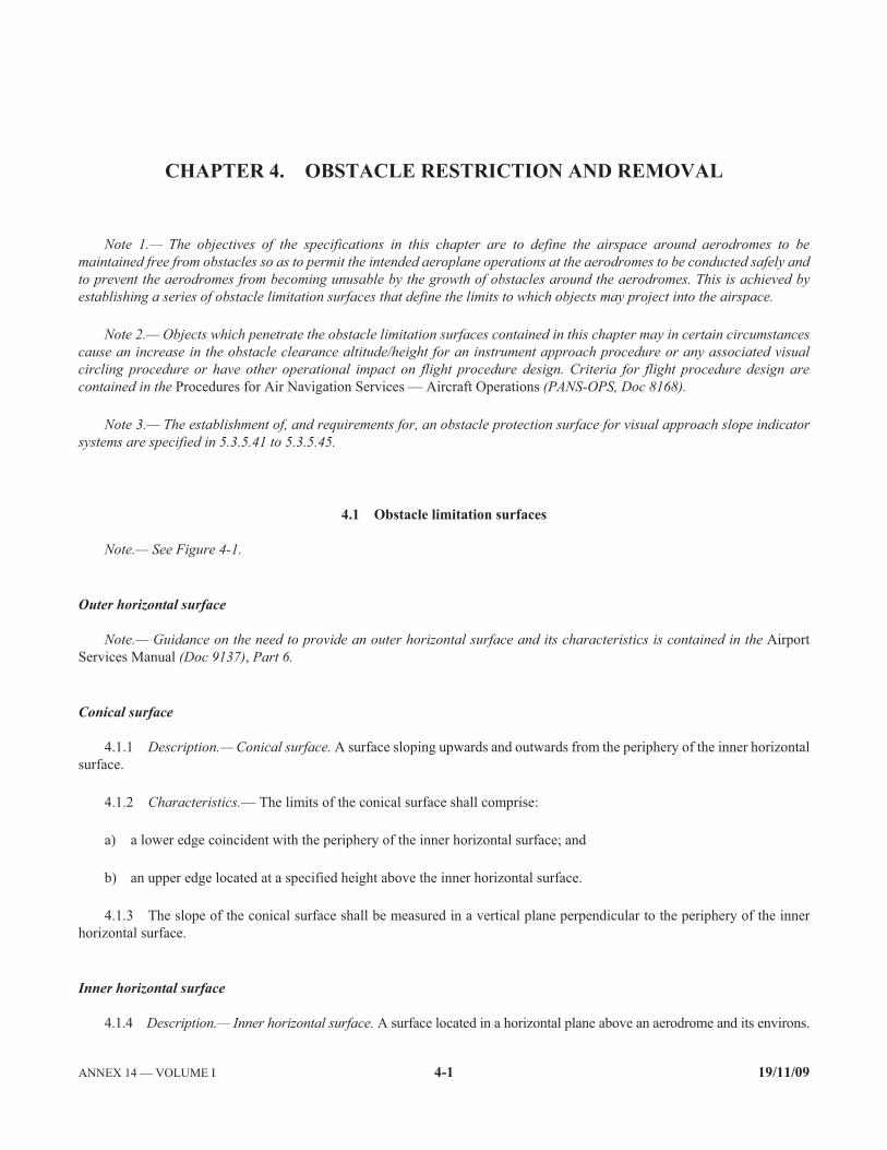
ANNEX 14 — VOLUME I 4-1 19/11/09
CHAPTER 4. OBSTACLE RESTRICTION AND REMOVAL
Note 1.— The objectives of the specifications in this chapter are to define the airspace around aerodromes to be maintained free from obstacles so as to permit the intended aeroplane operations at the aerodromes to be conducted safely and to prevent the aerodromes from becoming unusable by the growth of obstacles around the aerodromes. This is achieved by establishing a series of obstacle limitation surfaces that define the limits to which objects may project into the airspace.
Note 2.— Objects which penetrate the obstacle limitation surfaces contained in this chapter may in certain circumstancescause an increase in the obstacle clearance altitude/height for an instrument approach procedure or any associated visual circling procedure or have other operational impact on flight procedure design. Criteria for flight procedure design are contained in the Procedures for Air Navigation Services — Aircraft Operations (PANS-OPS, Doc 8168).
Note 3.— The establishment of, and requirements for, an obstacle protection surface for visual approach slope indicator systems are specified in 5.3.5.41 to 5.3.5.45.
4.1 Obstacle limitation surfaces
Note.— See Figure 4-1.
Outer horizontal surface
Note.— Guidance on the need to provide an outer horizontal surface and its characteristics is contained in the Airport Services Manual (Doc 9137), Part 6.
Conical surface
4.1.1 Description.— Conical surface. A surface sloping upwards and outwards from the periphery of the inner horizontal surface.
4.1.2 Characteristics.— The limits of the conical surface shall comprise:
a) a lower edge coincident with the periphery of the inner horizontal surface; and
b) an upper edge located at a specified height above the inner horizontal surface.
4.1.3 The slope of the conical surface shall be measured in a vertical plane perpendicular to the periphery of the inner horizontal surface.
Inner horizontal surface
4.1.4 Description.— Inner horizontal surface. A surface located in a horizontal plane above an aerodrome and its environs.

Annex 14 — Aerodromes Volume I
19/11/09 4-2
4.1.5 Characteristics.— The radius or outer limits of the inner horizontal surface shall be measured from a reference point or points established for such purpose.
Note.— The shape of the inner horizontal surface need not necessarily be circular. Guidance on determining the extent of the inner horizontal surface is contained in the Airport Services Manual (Doc 9137), Part 6.
4.1.6 The height of the inner horizontal surface shall be measured above an elevation datum established for such purpose.
Note.— Guidance on determining the elevation datum is contained in the Airport Services Manual (Doc 9137), Part 6.
Approach surface
4.1.7 Description.— Approach surface. An inclined plane or combination of planes preceding the threshold.
4.1.8 Characteristics.— The limits of the approach surface shall comprise:
a) an inner edge of specified length, horizontal and perpendicular to the extended centre line of the runway and located at a specified distance before the threshold;
b) two sides originating at the ends of the inner edge and diverging uniformly at a specified rate from the extended centre line of the runway;
c) an outer edge parallel to the inner edge; and
d) The above surfaces shall be varied when lateral offset, offset or curved approaches are utilized, specifically, two sides originating at the ends of the inner edge and diverging uniformly at a specified rate from the extended centre line of the lateral offset, offset or curved ground track.
4.1.9 The elevation of the inner edge shall be equal to the elevation of the midpoint of the threshold.
4.1.10 The slope(s) of the approach surface shall be measured in the vertical plane containing the centre line of the runway and shall continue containing the centre line of any lateral offset or curved ground track.
Note.— See Figure 4-2.
Inner approach surface
4.1.11 Description.— Inner approach surface. A rectangular portion of the approach surface immediately preceding the threshold.
4.1.12 Characteristics.— The limits of the inner approach surface shall comprise:
a) an inner edge coincident with the location of the inner edge of the approach surface but of its own specified length;
b) two sides originating at the ends of the inner edge and extending parallel to the vertical plane containing the centre lineof the runway; and
c) an outer edge parallel to the inner edge.
Transitional surface
4.1.13 Description.— Transitional surface. A complex surface along the side of the strip and part of the side of the approach surface, that slopes upwards and outwards to the inner horizontal surface.

Chapter 4 Annex 14 — Aerodromes
4-3 19/11/09
Figure 4-1. Obstacle limitation surfaces
Conical
Transitional
ApproachApproach
Inner approach Strip
Inner horizontal
Conical
Take-off climb
B
A A
B
Approach Take-off climb
Inner horizontalConical
Conical
Transitional
Section A-A
Section B-B
Approach Transitional
Inner horizontal
Inner approach
See Figure 4-2 for inner transitional and balked landing obstacle limitation surfaces andAttachment B for a three-dimensional view

Annex 14 — Aerodromes Volume I
19/11/09 4-4
Figure 4-2. Inner approach, inner transitional and balked landing obstacle limitation surfaces
4.1.14 Characteristics.— The limits of a transitional surface shall comprise:
a) a lower edge beginning at the intersection of the side of the approach surface with the inner horizontal surface and extending down the side of the approach surface to the inner edge of the approach surface and from there along the length of the strip parallel to the runway centre line; and
b) an upper edge located in the plane of the inner horizontal surface.
4.1.15 The elevation of a point on the lower edge shall be:
a) along the side of the approach surface — equal to the elevation of the approach surface at that point; and
b) along the strip — equal to the elevation of the nearest point on the centre line of the runway or its extension.
B
B
A ABalkedlanding
Inner transitional
Inner transitional
Inner transitional Inner horizontal
Inner approach
Balkedlanding
Balkedlanding
Section A-A
Section B-B

Chapter 4 Annex 14 — Aerodromes
4-5 19/11/09
Note.— As a result of b) the transitional surface along the strip will be curved if the runway profile is curved, or a plane ifthe runway profile is a straight line. The intersection of the transitional surface with the inner horizontal surface will also be a curved or a straight line depending on the runway profile.
4.1.16 The slope of the transitional surface shall be measured in a vertical plane at right angles to the centre line of therunway.
Inner transitional surface
Note.— It is intended that the inner transitional surface be the controlling obstacle limitation surface for navigation aids, aircraft and other vehicles that must be near the runway and which is not to be penetrated except for frangible objects. The transitional surface described in 4.1.13 is intended to remain as the controlling obstacle limitation surface for buildings, etc.
4.1.17 Description.— Inner transitional surface. A surface similar to the transitional surface but closer to the runway.
4.1.18 Characteristics.— The limits of an inner transitional surface shall comprise:
a) a lower edge beginning at the end of the inner approach surface and extending down the side of the inner approach surface to the inner edge of that surface, from there along the strip parallel to the runway centre line to the inner edge of the balked landing surface and from there up the side of the balked landing surface to the point where the side intersects the inner horizontal surface; and
b) an upper edge located in the plane of the inner horizontal surface.
4.1.19 The elevation of a point on the lower edge shall be:
a) along the side of the inner approach surface and balked landing surface — equal to the elevation of the particular surface at that point; and
b) along the strip — equal to the elevation of the nearest point on the centre line of the runway or its extension.
Note.— As a result of b) the inner transitional surface along the strip will be curved if the runway profile is curved or a plane if the runway profile is a straight line. The intersection of the inner transitional surface with the inner horizontal surfacewill also be a curved or straight line depending on the runway profile.
4.1.20 The slope of the inner transitional surface shall be measured in a vertical plane at right angles to the centre line of the runway.
Balked landing surface
4.1.21 Description.— Balked landing surface. An inclined plane located at a specified distance after the threshold, extending between the inner transitional surface.
4.1.22 Characteristics.— The limits of the balked landing surface shall comprise:
a) an inner edge horizontal and perpendicular to the centre line of the runway and located at a specified distance after the threshold;
b) two sides originating at the ends of the inner edge and diverging uniformly at a specified rate from the vertical plane containing the centre line of the runway; and

Annex 14 — Aerodromes Volume I
19/11/09 4-6
c) an outer edge parallel to the inner edge and located in the plane of the inner horizontal surface.
4.1.23 The elevation of the inner edge shall be equal to the elevation of the runway centre line at the location of the inneredge.
4.1.24 The slope of the balked landing surface shall be measured in the vertical plane containing the centre line of the runway.
Take-off climb surface
4.1.25 Description.— Take-off climb surface. An inclined plane or other specified surface beyond the end of a runway or clearway.
4.1.26 Characteristics.— The limits of the take-off climb surface shall comprise:
a) an inner edge horizontal and perpendicular to the centre line of the runway and located either at a specified distance beyond the end of the runway or at the end of the clearway when such is provided and its length exceeds the specified distance;
b) two sides originating at the ends of the inner edge, diverging uniformly at a specified rate from the take-off track to a specified final width and continuing thereafter at that width for the remainder of the length of the take-off climb surface; and
c) an outer edge horizontal and perpendicular to the specified take-off track.
4.1.27 The elevation of the inner edge shall be equal to the highest point on the extended runway centre line between the end of the runway and the inner edge, except that when a clearway is provided the elevation shall be equal to the highest pointon the ground on the centre line of the clearway.
4.1.28 In the case of a straight take-off flight path, the slope of the take-off climb surface shall be measured in the vertical plane containing the centre line of the runway.
4.1.29 In the case of a take-off flight path involving a turn, the take-off climb surface shall be a complex surface containing the horizontal normals to its centre line, and the slope of the centre line shall be the same as that for a straighttake-off flight path.
4.2 Obstacle limitation requirements
Note.— The requirements for obstacle limitation surfaces are specified on the basis of the intended use of a runway, i.e. take-off or landing and type of approach, and are intended to be applied when such use is made of the runway. In cases where operations are conducted to or from both directions of a runway, then the function of certain surfaces may be nullified becauseof more stringent requirements of another lower surface.
Non-instrument runways
4.2.1 The following obstacle limitation surfaces shall be established for a non-instrument runway:
— conical surface; — inner horizontal surface; — approach surface; and — transitional surfaces.
Chapter 4 Annex 14 — Aerodromes
4-7 19/11/09
4.2.2 The heights and slopes of the surfaces shall not be greater than, and their other dimensions not less than, those specified in Table 4-1.
4.2.3 New objects or extensions of existing objects shall not be permitted above an approach or transitional surface except when, in the opinion of the appropriate authority, the new object or extension would be shielded by an existing immovable object.
Note.— Circumstances in which the shielding principle may reasonably be applied are described in the Airport Services Manual (Doc 9137), Part 6.
4.2.4 Recommendation.— New objects or extensions of existing objects should not be permitted above the conical surface or inner horizontal surface except when, in the opinion of the appropriate authority, the object would be shielded by anexisting immovable object, or after aeronautical study it is determined that the object would not adversely affect the safety orsignificantly affect the regularity of operations of aeroplanes.
4.2.5 Recommendation.— Existing objects above any of the surfaces required by 4.2.1 should as far as practicable be removed except when, in the opinion of the appropriate authority, the object is shielded by an existing immovable object, or after aeronautical study it is determined that the object would not adversely affect the safety or significantly affect the regularity of operations of aeroplanes.
Note.— Because of transverse or longitudinal slopes on a strip, in certain cases the inner edge or portions of the inner edge ofthe approach surface may be below the corresponding elevation of the strip. It is not intended that the strip be graded to conform with the inner edge of the approach surface, nor is it intended that terrain or objects which are above the approach surface beyondthe end of the strip, but below the level of the strip, be removed unless it is considered they may endanger aeroplanes.
4.2.6 Recommendation.— In considering proposed construction, account should be taken of the possible future development of an instrument runway and consequent requirement for more stringent obstacle limitation surfaces.
Non-precision approach runways
4.2.7 The following obstacle limitation surfaces shall be established for a non-precision approach runway:
— conical surface; — inner horizontal surface; — approach surface; and — transitional surfaces.
4.2.8 The heights and slopes of the surfaces shall not be greater than, and their other dimensions not less than, those specified in Table 4-1, except in the case of the horizontal section of the approach surface (see 4.2.9).
4.2.9 The approach surface shall be horizontal beyond the point at which the 2.5 per cent slope intersects:
a) a horizontal plane 150 m above the threshold elevation; or
b) the horizontal plane passing through the top of any object that governs the obstacle clearance altitude/height (OCA/H);
whichever is the higher.
4.2.10 New objects or extensions of existing objects shall not be permitted above an approach surface within 3 000 m of the inner edge or above a transitional surface except when, in the opinion of the appropriate authority, the new object or extension would be shielded by an existing immovable object.
Note.— Circumstances in which the shielding principle may reasonably be applied are described in the Airport Services Manual (Doc 9137), Part 6.

Annex 14 — Aerodromes Volume I
19/11/09 4-8
Table 4-1. Dimensions and slopes of obstacle limitation surfaces — Approach runways
APPROACH RUNWAYS
RUNWAY CLASSIFICATION Precision approach category Non-instrument
Code number Non-precision approach
Code number I
Code number II or III
Code number Surface and dimensionsa 1 2 3 4 1,2 3 4 1,2 3,4 3,4
(1) (2) (3) (4) (5) (6) (7) (8) (9) (10) (11)
CONICAL Slope 5% 5% 5% 5% 5% 5% 5% 5% 5% 5% Height 35 m 55 m 75 m 100 m 60 m 75 m 100 m 60 m 100 m 100 m
INNER HORIZONTAL Height 45 m 45 m 45 m 45 m 45 m 45 m 45 m 45 m 45 m 45 m Radius 2 000 m 2 500 m 4 000 m 4 000 m 3 500 m 4 000 m 4 000 m 3 500 m 4 000 m 4 000 m
INNER APPROACH Width — — — — — — — 90 m 120 me 120 me
Distance from threshold — — — — — — — 60 m 60 m 60 m Length — — — — — — — 900 m 900 m 900 m Slope 2.5% 2% 2%
APPROACH Length of inner edge 60 m 80 m 150 m 150 m 150 m 300 m 300 m 150 m 300 m 300 m Distance from threshold 30 m 60 m 60 m 60 m 60 m 60 m 60 m 60 m 60 m 60 m Divergence (each side) 10% 10% 10% 10% 15% 15% 15% 15% 15% 15%
First section Length 1 600 m 2 500 m 3 000 m 3 000 m 2 500 m 3 000 m 3 000 m 3 000 m 3 000 m 3 000 m Slope 5% 4% 3.33% 2.5% 3.33% 2% 2% 2.5% 2% 2%
Second section Length — — — — — 3 600 mb 3 600 mb 12 000 m 3 600 mb 3 600 mb
Slope — — — — — 2.5% 2.5% 3% 2.5% 2.5%
Horizontal section Length — — — — — 8 400 mb 8 400 mb — 8 400 mb 8 400 mb
Total length — — — — — 15 000 m 15 000 m 15 000 m 15 000 m 15 000 m
TRANSITIONAL Slope 20% 20% 14.3% 14.3% 20% 14.3% 14.3% 14.3% 14.3% 14.3%
INNER TRANSITIONAL Slope — — — — — — — 40% 33.3% 33.3%
BALKED LANDING SURFACE Length of inner edge — — — — — — — 90 m 120 me 120 me
Distance from threshold — — — — — — — c 1 800 md 1 800 md
Divergence (each side) — — — — — — — 10% 10% 10% Slope — — — — — — — 4% 3.33% 3.33%
a. All dimensions are measured horizontally unless specified otherwise. b. Variable length (see 4.2.9 or 4.2.17). c. Distance to the end of strip. d. Or end of runway whichever is less.
e. Where the code letter is F (Column (3) of Table 1-1), the width isincreased to 155 m. For information on code letter F aeroplanes equippedwith digital avionics that provide steering commands to maintain an established track during the go-around manoeuvre, see Circular 301 —New Larger Aeroplanes — Infringement of the Obstacle Free Zone: Operational Measures and Aeronautical Study.

Chapter 4 Annex 14 — Aerodromes
4-9 19/11/09
4.2.11 Recommendation.— New objects or extensions of existing objects should not be permitted above the approach surface beyond 3 000 m from the inner edge, the conical surface or inner horizontal surface except when, in the opinion of the appropriate authority, the object would be shielded by an existing immovable object, or after aeronautical study it is determined that the object would not adversely affect the safety or significantly affect the regularity of operations of aeroplanes.
4.2.12 Recommendation.— Existing objects above any of the surfaces required by 4.2.7 should as far as practicable be removed except when, in the opinion of the appropriate authority, the object is shielded by an existing immovable object, or after aeronautical study it is determined that the object would not adversely affect the safety or significantly affect the regularity of operations of aeroplanes.
Note.— Because of transverse or longitudinal slopes on a strip, in certain cases the inner edge or portions of the inner edge of the approach surface may be below the corresponding elevation of the strip. It is not intended that the strip be graded to conform with the inner edge of the approach surface, nor is it intended that terrain or objects which are above the approach surface beyond the end of the strip, but below the level of the strip, be removed unless it is considered they may endanger aeroplanes.
Precision approach runways
Note 1.— See 9.9 for information regarding siting of equipment and installations on operational areas.
Note 2.— Guidance on obstacle limitation surfaces for precision approach runways is given in the Airport Services Manual (Doc 9137), Part 6.
4.2.13 The following obstacle limitation surfaces shall be established for a precision approach runway category I:
— conical surface; — inner horizontal surface; — approach surface; and — transitional surfaces.
4.2.14 Recommendation.— The following obstacle limitation surfaces should be established for a precision approach runway category I:
— inner approach surface; — inner transitional surfaces; and — balked landing surface.
4.2.15 The following obstacle limitation surfaces shall be established for a precision approach runway category II or III:
— conical surface; — inner horizontal surface; — approach surface and inner approach surface; — transitional surfaces; — inner transitional surfaces; and — balked landing surface.
4.2.16 The heights and slopes of the surfaces shall not be greater than, and their other dimensions not less than, those specified in Table 4-1, except in the case of the horizontal section of the approach surface (see 4.2.17).
4.2.17 The approach surface shall be horizontal beyond the point at which the 2.5 per cent slope intersects:

Annex 14 — Aerodromes Volume I
19/11/09 4-10
a) a horizontal plane 150 m above the threshold elevation; or
b) the horizontal plane passing through the top of any object that governs the obstacle clearance limit;
whichever is the higher.
4.2.18 Fixed objects shall not be permitted above the inner approach surface, the inner transitional surface or the balked landing surface, except for frangible objects which because of their function must be located on the strip. Mobile objects shallnot be permitted above these surfaces during the use of the runway for landing.
4.2.19 New objects or extensions of existing objects shall not be permitted above an approach surface or a transitional surface except when, in the opinion of the appropriate authority, the new object or extension would be shielded by an existing immovable object.
Note.— Circumstances in which the shielding principle may reasonably be applied are described in the Airport Services Manual (Doc 9137), Part 6.
4.2.20 Recommendation.— New objects or extensions of existing objects should not be permitted above the conical surface and the inner horizontal surface except when, in the opinion of the appropriate authority, an object would be shielded by an existing immovable object, or after aeronautical study it is determined that the object would not adversely affect the safety or significantly affect the regularity of operations of aeroplanes.
4.2.21 Recommendation.— Existing objects above an approach surface, a transitional surface, the conical surface and inner horizontal surface should as far as practicable be removed except when, in the opinion of the appropriate authority, an object is shielded by an existing immovable object, or after aeronautical study it is determined that the object would not adversely affect the safety or significantly affect the regularity of operations of aeroplanes.
Note.— Because of transverse or longitudinal slopes on a strip, in certain cases the inner edge or portions of the inner edge of the approach surface may be below the corresponding elevation of the strip. It is not intended that the strip be graded to conform with the inner edge of the approach surface, nor is it intended that terrain or objects which are above the approach surface beyond the end of the strip, but below the level of the strip, be removed unless it is considered they may endanger aeroplanes.
Runways meant for take-off
4.2.22 The following obstacle limitation surface shall be established for a runway meant for take-off:
— take-off climb surface.
4.2.23 The dimensions of the surface shall be not less than the dimensions specified in Table 4-2, except that a lesser length may be adopted for the take-off climb surface where such lesser length would be consistent with procedural measures adopted to govern the outward flight of aeroplanes.
4.2.24 Recommendation.— The operational characteristics of aeroplanes for which the runway is intended should be examined to see if it is desirable to reduce the slope specified in Table 4-2 when critical operating conditions are to be cateredto. If the specified slope is reduced, corresponding adjustment in the length of the take-off climb surface should be made so asto provide protection to a height of 300 m.
Note.— When local conditions differ widely from sea level standard atmospheric conditions, it may be advisable for the slope specified in Table 4-2 to be reduced. The degree of this reduction depends on the divergence between local conditions andsea level standard atmospheric conditions, and on the performance characteristics and operational requirements of the aeroplanes for which the runway is intended.

Chapter 4 Annex 14 — Aerodromes
4-11 19/11/09
Table 4-2. Dimensions and slopes of obstacle limitation surfaces
RUNWAYS MEANT FOR TAKE-OFF
Code number Surface and dimensionsa 1 2 3 or 4
(1) (2) (3) (4)
TAKE-OFF CLIMB
Length of inner edge 60 m 80 m 180 m
Distance from runway endb 30 m 60 m 60 m
Divergence (each side) 10% 10% 12.5%
Final width 380 m 580 m 1 200 m 1 800 mc
Length 1 600 m 2 500 m 15 000 m
Slope 5% 4% 2%d
a. All dimensions are measured horizontally unless specified otherwise. b. The take-off climb surface starts at the end of the clearway if the clearway length exceeds the specified distance.c. 1 800 m when the intended track includes changes of heading greater than 15° for operations conducted in IMC,
VMC by night. d. See 4.2.24 and 4.2.26.
4.2.25 New objects or extensions of existing objects shall not be permitted above a take-off climb surface except when, in the opinion of the appropriate authority, the new object or extension would be shielded by an existing immovable object.
Note.— Circumstances in which the shielding principle may reasonably be applied are described in the Airport Services Manual (Doc 9137), Part 6.
4.2.26 Recommendation.— If no object reaches the 2 per cent (1:50) take-off climb surface, new objects should be limited to preserve the existing obstacle free surface or a surface down to a slope of 1.6 per cent (1:62.5).
4.2.27 Recommendation.— Existing objects that extend above a take-off climb surface should as far as practicable be removed except when, in the opinion of the appropriate authority, an object is shielded by an existing immovable object, or after aeronautical study it is determined that the object would not adversely affect the safety or significantly affect the regularity of operations of aeroplanes.
Note.— Because of transverse slopes on a strip or clearway, in certain cases portions of the inner edge of the take-off climb surface may be below the corresponding elevation of the strip or clearway. It is not intended that the strip or clearway be graded to conform with the inner edge of the take-off climb surface, nor is it intended that terrain or objects which are abovethe take-off climb surface beyond the end of the strip or clearway, but below the level of the strip or clearway, be removed unless it is considered they may endanger aeroplanes. Similar considerations apply at the junction of a clearway and strip where differences in transverse slopes exist.

Annex 14 — Aerodromes Volume I
19/11/09 4-12
4.3 Objects outside the obstacle limitation surfaces
4.3.1 Recommendation.— Arrangements should be made to enable the appropriate authority to be consulted concerning proposed construction beyond the limits of the obstacle limitation surfaces that extend above a height established by that authority, in order to permit an aeronautical study of the effect of such construction on the operation of aeroplanes.
4.3.2 Recommendation.— In areas beyond the limits of the obstacle limitation surfaces, at least those objects which extend to a height of 150 m or more above ground elevation should be regarded as obstacles, unless a special aeronautical study indicates that they do not constitute a hazard to aeroplanes.
Note.— This study may have regard to the nature of operations concerned and may distinguish between day and night operations.
4.4 Other objects
4.4.1 Recommendation.— Objects which do not project through the approach surface but which would nevertheless adversely affect the optimum siting or performance of visual or non-visual aids should, as far as practicable, be removed.
4.4.2 Recommendation.— Anything which may, in the opinion of the appropriate authority after aeronautical study, endanger aeroplanes on the movement area or in the air within the limits of the inner horizontal and conical surfaces should beregarded as an obstacle and should be removed in so far as practicable.
Note.— In certain circumstances, objects that do not project above any of the surfaces enumerated in 4.1 may constitute a hazard to aeroplanes as, for example, where there are one or more isolated objects in the vicinity of an aerodrome.
_____________________

ANNEX 14 — VOLUME I 5-1 19/11/09
CHAPTER 5. VISUAL AIDS FOR NAVIGATION
5.1 Indicators and signalling devices
5.1.1 Wind direction indicator
Application
5.1.1.1 An aerodrome shall be equipped with at least one wind direction indicator.
Location
5.1.1.2 A wind direction indicator shall be located so as to be visible from aircraft in flight or on the movement area andin such a way as to be free from the effects of air disturbances caused by nearby objects.
Characteristics
5.1.1.3 Recommendation.— The wind direction indicator should be in the form of a truncated cone made of fabric and should have a length of not less than 3.6 m and a diameter, at the larger end, of not less than 0.9 m. It should be constructed so that it gives a clear indication of the direction of the surface wind and a general indication of the wind speed. The colour orcolours should be so selected as to make the wind direction indicator clearly visible and understandable from a height of at least 300 m, having regard to background. Where practicable, a single colour, preferably white or orange, should be used. Where a combination of two colours is required to give adequate conspicuity against changing backgrounds, they should preferably be orange and white, red and white, or black and white, and should be arranged in five alternate bands, the first andlast bands being the darker colour.
5.1.1.4 Recommendation.— The location of at least one wind direction indicator should be marked by a circular band 15 m in diameter and 1.2 m wide. The band should be centred about the wind direction indicator support and should be in a colour chosen to give adequate conspicuity, preferably white.
5.1.1.5 Recommendation.— Provision should be made for illuminating at least one wind indicator at an aerodrome intended for use at night.
5.1.2 Landing direction indicator
Location
5.1.2.1 Where provided, a landing direction indicator shall be located in a conspicuous place on the aerodrome.
Characteristics
5.1.2.2 Recommendation.— The landing direction indicator should be in the form of a “T”.

Annex 14 — Aerodromes Volume I
19/11/09 5-2
5.1.2.3 The shape and minimum dimensions of a landing “T” shall be as shown in Figure 5-1. The colour of the landing “T” shall be either white or orange, the choice being dependent on the colour that contrasts best with the background against which the indicator will be viewed. Where required for use at night the landing “T” shall either be illuminated or outlined by white lights.
5.1.3 Signalling lamp
Application
5.1.3.1 A signalling lamp shall be provided at a controlled aerodrome in the aerodrome control tower.
Characteristics
5.1.3.2 Recommendation.— A signalling lamp should be capable of producing red, green and white signals, and of:
a) being aimed manually at any target as required;
b) giving a signal in any one colour followed by a signal in either of the two other colours; and
c) transmitting a message in any one of the three colours by Morse Code up to a speed of at least four words per minute.
When selecting the green light, use should be made of the restricted boundary of green as specified in Appendix 1, 2.1.2.
5.1.3.3 Recommendation.— The beam spread should be not less than 1° nor greater than 3°, with negligible light beyond 3°. When the signalling lamp is intended for use in the daytime the intensity of the coloured light should be not less than 6 000 cd.
Figure 5-1. Landing direction indicator
0.4
m
0.4 m 4 m
4m

Chapter 5 Annex 14 — Aerodromes
5-3 19/11/09
5.1.4 Signal panels and signal area
Note.— The inclusion of detailed specifications for a signal area in this section is not intended to imply that one has to be provided. Attachment A, Section 16, provides guidance on the need to provide ground signals. Annex 2, Appendix 1, specifies the shape, colour and use of visual ground signals. The Aerodrome Design Manual (Doc 9157), Part 4, provides guidance on their design.
Location of signal area
5.1.4.1 Recommendation.— The signal area should be located so as to be visible for all angles of azimuth above an angle of 10° above the horizontal when viewed from a height of 300 m.
Characteristics of signal area
5.1.4.2 The signal area shall be an even horizontal surface at least 9 m square.
5.1.4.3 Recommendation.— The colour of the signal area should be chosen to contrast with the colours of the signal panels used, and it should be surrounded by a white border not less than 0.3 m wide.
5.2 Markings
5.2.1 General
Interruption of runway markings
5.2.1.1 At an intersection of two (or more) runways the markings of the more important runway, except for the runway side stripe marking, shall be displayed and the markings of the other runway(s) shall be interrupted. The runway side stripe marking of the more important runway may be either continued across the intersection or interrupted.
5.2.1.2 Recommendation.— The order of importance of runways for the display of runway markings should be as follows:
1st — precision approach runway;
2nd — non-precision approach runway; and
3rd — non-instrument runway.
5.2.1.3 At an intersection of a runway and taxiway the markings of the runway shall be displayed and the markings of the taxiway interrupted, except that runway side stripe markings may be interrupted.
Note.— See 5.2.8.7 regarding the manner of connecting runway and taxiway centre line markings.
Colour and conspicuity
5.2.1.4 Runway markings shall be white.

Annex 14 — Aerodromes Volume I
19/11/09 5-4
Note 1.— It has been found that, on runway surfaces of light colour, the conspicuity of white markings can be improved by outlining them in black.
Note 2.— It is preferable that the risk of uneven friction characteristics on markings be reduced in so far as practicable by the use of a suitable kind of paint.
Note 3.— Markings may consist of solid areas or a series of longitudinal stripes providing an effect equivalent to the solid areas.
5.2.1.5 Taxiway markings, runway turn pad markings and aircraft stand markings shall be yellow.
5.2.1.6 Apron safety lines shall be of a conspicuous colour which shall contrast with that used for aircraft stand markings.
5.2.1.7 Recommendation.— At aerodromes where operations take place at night, pavement markings should be made with reflective materials designed to enhance the visibility of the markings.
Note.— Guidance on reflective materials is given in the Aerodrome Design Manual (Doc 9157), Part 4.
Unpaved taxiways
5.2.1.8 Recommendation.— An unpaved taxiway should be provided, so far as practicable, with the markings prescribed for paved taxiways.
5.2.2 Runway designation marking
Application
5.2.2.1 A runway designation marking shall be provided at the thresholds of a paved runway.
5.2.2.2 Recommendation.— A runway designation marking should be provided, so far as practicable, at the thresholds of an unpaved runway.
Location
5.2.2.3 A runway designation marking shall be located at a threshold as shown in Figure 5-2 as appropriate.
Note.— If the runway threshold is displaced from the extremity of the runway, a sign showing the designation of the runway may be provided for aeroplanes taking off.
Characteristics
5.2.2.4 A runway designation marking shall consist of a two-digit number and on parallel runways shall be supplemented with a letter. On a single runway, dual parallel runways and triple parallel runways the two-digit number shall be the whole number nearest the one-tenth of the magnetic North when viewed from the direction of approach. On four or more parallel runways, one set of adjacent runways shall be numbered to the nearest one-tenth magnetic azimuth and the other set of adjacent runways numbered to the next nearest one-tenth of the magnetic azimuth. When the above rule would give a single digit number, it shall be preceded by a zero.

Chapter 5 Annex 14 — Aerodromes
5-5 19/11/09
Figure 5-2. Runway designation, centre line and threshold markings
5.2.2.5 In the case of parallel runways, each runway designation number shall be supplemented by a letter as follows, in the order shown from left to right when viewed from the direction of approach:
— for two parallel runways: “L” “R”;
— for three parallel runways: “L” “C” “R”;
— for four parallel runways: “L” “R” “L” “R”;
— for five parallel runways: “L” “C” “R” “L” “R” or “L” “R” “L” “C” “R”; and
— for six parallel runways: “L” “C” “R” “L” “C” “R”.
5.2.2.6 The numbers and letters shall be in the form and proportion shown in Figure 5-3. The dimensions shall be not less than those shown in Figure 5-3, but where the numbers are incorporated in the threshold marking, larger dimensions shall be used in order to fill adequately the gap between the stripes of the threshold marking.
� �� � � �
2� 2�
9 m
mnm
9 m mnm
9 m mnm6 m mnm
50 m
mnm
50 m
mnm
12 m
12 m
12 m
12 m
30 m
30 m
30 m
30 m
30 m
20 m
20 m
20 m
6 m
mnm 6 m mnm 6 m mnm
30 m
mnm
30 m
mnm
30 m
mnm
A – General and all precisionapproach runways
Precisionapproachcategory I
and non-precisionapproach runways
0.45 m mnmPrecision
approach categoryII and IIIrunways
0.9 m mnm
B – Parallel runways C – Optional pattern
22.5 m
� = 1.8 maprx.
Non-precisionapproachrunways
0.45 m mnmNon-instrument
runways0.3 m mnm
>
>

Annex 14 — Aerodromes Volume I
19/11/09 5-6
5.2.3 Runway centre line marking
Application
5.2.3.1 A runway centre line marking shall be provided on a paved runway.
Location
5.2.3.2 A runway centre line marking shall be located along the centre line of the runway between the runway designation markings as shown in Figure 5-2, except when interrupted in compliance with 5.2.1.1.
Characteristics
5.2.3.3 A runway centre line marking shall consist of a line of uniformly spaced stripes and gaps. The length of a stripe plus a gap shall be not less than 50 m or more than 75 m. The length of each stripe shall be at least equal to the length of the gap or 30 m, whichever is greater.
5.2.3.4 The width of the stripes shall be not less than:
— 0.90 m on precision approach category II and III runways;
— 0.45 m on non-precision approach runways where the code number is 3 or 4, and precision approach category I runways; and
— 0.30 m on non-precision approach runways where the code number is 1 or 2, and on non-instrument runways.
5.2.4 Threshold marking
Application
5.2.4.1 A threshold marking shall be provided at the threshold of a paved instrument runway, and of a paved non- instrument runway where the code number is 3 or 4 and the runway is intended for use by international commercial air transport.
5.2.4.2 Recommendation.— A threshold marking should be provided at the threshold of a paved non-instrument runway where the code number is 3 or 4 and the runway is intended for use by other than international commercial air transport.
5.2.4.3 Recommendation.— A threshold marking should be provided, so far as practicable, at the thresholds of an unpaved runway.
Note.— The Aerodrome Design Manual (Doc 9157), Part 4, shows a form of marking which has been found satisfactory for the marking of downward slopes immediately before the threshold.
Location
5.2.4.4 The stripes of the threshold marking shall commence 6 m from the threshold.

Chapter 5 Annex 14 — Aerodromes
5-7 19/11/09
Figure 5-3. Form and proportions of numbers and letters for runway designation markings
Note.— All units are expressed in metres.
0.3
0.8
9.0
4.0
2.4
2.6
0.5
1.5 1.5
1.5
1.5
1.5
1.5
1.5
1.5
1.51.
11.
5
1.0
1.5
1.4
5.4
3.6
1.11.1
3.0
3.0 3.0
3.0 3.0 3.0
3.03.5
3.0 3.03.9
2.7
2.9
3.4
1.5
1.5
1.5
1.5
1.5
1.5
1.5
1.5
1.5
2.7
4.8 0.8
0.3
9.0
0.8
2.0
2.0
5.5
3.9
5.1
1.0
2.0
2.0 0.8
4.0
6.0
0.8
9.0
3.02.2
3.8
5.6
0.8
9.0
3.8
5.2
2.1
4.8
2.1
1.5

Annex 14 — Aerodromes Volume I
19/11/09 5-8
Characteristics
5.2.4.5 A runway threshold marking shall consist of a pattern of longitudinal stripes of uniform dimensions disposed symmetrically about the centre line of a runway as shown in Figure 5-2 (A) and (B) for a runway width of 45 m. The number of stripes shall be in accordance with the runway width as follows:
Number of Runway width stripes
18 m 14 23 m 16 30 m 18 45 m 12 60 m 16
except that on non-precision approach and non-instrument runways 45 m or greater in width, they may be as shown in Figure 5-2 (C).
5.2.4.6 The stripes shall extend laterally to within 3 m of the edge of a runway or to a distance of 27 m on either side of a runway centre line, whichever results in the smaller lateral distance. Where a runway designation marking is placed within a threshold marking there shall be a minimum of three stripes on each side of the centre line of the runway. Where a runway designation marking is placed above a threshold marking, the stripes shall be continued across the runway. The stripes shall beat least 30 m long and approximately 1.80 m wide with spacings of approximately 1.80 m between them except that, where the stripes are continued across a runway, a double spacing shall be used to separate the two stripes nearest the centre line of therunway, and in the case where the designation marking is included within the threshold marking this spacing shall be 22.5 m.
Transverse stripe
5.2.4.7 Recommendation.— Where a threshold is displaced from the extremity of a runway or where the extremity of a runway is not square with the runway centre line, a transverse stripe as shown in Figure 5-4 (B) should be added to the threshold marking.
5.2.4.8 A transverse stripe shall be not less than 1.80 m wide.
Arrows
5.2.4.9 Where a runway threshold is permanently displaced, arrows conforming to Figure 5-4 (B) shall be provided on the portion of the runway before the displaced threshold.
5.2.4.10 When a runway threshold is temporarily displaced from the normal position, it shall be marked as shown in Figure 5-4 (A) or 5-4 (B) and all markings prior to the displaced threshold shall be obscured except the runway centre line marking, which shall be converted to arrows.
Note 1.— In the case where a threshold is temporarily displaced for only a short period of time, it has been found satisfactory to use markers in the form and colour of a displaced threshold marking rather than attempting to paint this marking on the runway.
Note 2.— When the runway before a displaced threshold is unfit for the surface movement of aircraft, closed markings, as described in 7.1.4, are required to be provided.

Chapter 5 Annex 14 — Aerodromes
5-9 19/11/09
Figure 5-4. Displaced threshold markings
5.2.5 Aiming point marking
Application
5.2.5.1 The provisions of Sections 5.2.5 and 5.2.6 shall not require the replacement of existing markings before 1 January 2005.
5.2.5.2 An aiming point marking shall be provided at each approach end of a paved instrument runway where the code number is 2, 3 or 4.
5.2.5.3 Recommendation.— An aiming point marking should be provided at each approach end of:
a) a paved non-instrument runway where the code number is 3 or 4;
b) a paved instrument runway where the code number is 1;
when additional conspicuity of the aiming point is desirable.
h mnm12h3
1.2 m mnmh = 10 m mnm
h5
Temporarilydisplacedthreshold
Runwayextremity
A – Temporarily displaced threshold B – Temporarily or permanentlydisplaced threshold
W
50 m
50 m
20 m
30 m
30 m
20 m
Transversestripe
1.80 m mnm
Displacedthreshold
Dimension ofarrow head
as in ‘A’
Runwayextremity
aprx. w2
>

Annex 14 — Aerodromes Volume I
19/11/09 5-10
Location
5.2.5.4 The aiming point marking shall commence no closer to the threshold than the distance indicated in the appropriate column of Table 5-1, except that, on a runway equipped with a visual approach slope indicator system, the beginning of the marking shall be coincident with the visual approach slope origin.
5.2.5.5 An aiming point marking shall consist of two conspicuous stripes. The dimensions of the stripes and the lateral spacing between their inner sides shall be in accordance with the provisions of the appropriate column of Table 5-1. Where a touchdown zone marking is provided, the lateral spacing between the markings shall be the same as that of the touchdown zone marking.
5.2.6 Touchdown zone marking
Application
5.2.6.1 A touchdown zone marking shall be provided in the touchdown zone of a paved precision approach runway where the code number is 2, 3 or 4.
5.2.6.2 Recommendation.— A touchdown zone marking should be provided in the touchdown zone of a paved non-precision approach or non-instrument runway where the code number is 3 or 4 and additional conspicuity of the touchdown zone is desirable.
Table 5-1. Location and dimensions of aiming point marking
Landing distance available
Location and dimensions (1)
Less than 800 m (2)
800 m up to but not including 1 200 m
(3)
1 200 m up to but not including 2 400 m
(4) 2 400 m and above
(5)
Distance from threshold to beginning of marking
150 m 250 m 300 m 400 m
Length of stripea 30–45 m 30–45 m 45–60 m 45–60 m
Width of stripe 4 m 6 m 6–10 mb 6–10 mb
Lateral spacing between inner sides of stripes
6 mc 9 mc 18–22.5 m 18–22.5 m
a. The greater dimensions of the specified ranges are intended to be used where increased conspicuity is required. b. The lateral spacing may be varied within these limits to minimize the contamination of the marking by rubber deposits. c. These figures were deduced by reference to the outer main gear wheel span which is element 2 of the aerodrome reference code at Chapter 1, Table 1-1.

Chapter 5 Annex 14 — Aerodromes
5-11 19/11/09
Location and characteristics
5.2.6.3 A touchdown zone marking shall consist of pairs of rectangular markings symmetrically disposed about the runway centre line with the number of such pairs related to the landing distance available and, where the marking is to be displayed at both the approach directions of a runway, the distance between the thresholds, as follows:
Landing distance available or the distance between thresholds Pair(s) of markings
less than 900 m 1
900 m up to but not including 1 200 m 2
1 200 m up to but not including 1 500 m 3
1 500 m up to but not including 2 400 m 4
2 400 m or more 6
5.2.6.4 A touchdown zone marking shall conform to either of the two patterns shown in Figure 5-5. For the pattern shown in Figure 5-5 (A), the markings shall be not less than 22.5 m long and 3 m wide. For the pattern shown in Figure�5-5�(B), each stripe of each marking shall be not less than 22.5 m long and 1.8 m wide with a spacing of 1.5 m between adjacent stripes. The lateral spacing between the inner sides of the rectangles shall be equal to that of the aiming point marking where provided. Where an aiming point marking is not provided, the lateral spacing between the inner sides of the rectangles shall correspond tothe lateral spacing specified for the aiming point marking in Table 5-1 (columns 2, 3, 4 or 5, as appropriate). The pairs of markings shall be provided at longitudinal spacings of 150 m beginning from the threshold, except that pairs of touchdown zone markings coincident with or located within 50 m of an aiming point marking shall be deleted from the pattern.
5.2.6.5 Recommendation.— On a non-precision approach runway where the code number is 2, an additional pair of touchdown zone marking stripes should be provided 150 m beyond the beginning of the aiming point marking.
5.2.7 Runway side stripe marking
Application
5.2.7.1 A runway side stripe marking shall be provided between the thresholds of a paved runway where there is a lack of contrast between the runway edges and the shoulders or the surrounding terrain.
5.2.7.2 Recommendation.— A runway side stripe marking should be provided on a precision approach runway irrespective of the contrast between the runway edges and the shoulders or the surrounding terrain.
Location
5.2.7.3 Recommendation.— A runway side stripe marking should consist of two stripes, one placed along each edge of the runway with the outer edge of each stripe approximately on the edge of the runway, except that, where the runway is greaterthan 60 m in width, the stripes should be located 30 m from the runway centre line.
5.2.7.4 Recommendation.— Where a runway turn pad is provided, the runway side stripe marking should be continued between the runway and the runway turn pad.

Annex 14 — Aerodromes Volume I
19/11/09 5-12
Figure 5-5. Aiming point and touchdown zone markings (illustrated for a runway with a length of 2 400 m or more)
150 m150 m
400 m18 m
22.5 m
150 m 150 m
300 m 300 m
150 m 150 m
150 m 150 m
Touchdownzone
markings
Touchdownzone
markings
Stripes1.8 m width
1.5 m spacing22.5 m mnm length 18 m
22.5 m
Runwayside
stripemarkings
400 m
A – Basic pattern B – With distance coding
Aiming point marking(see Table 5-1 for
location and dimensions)

Chapter 5 Annex 14 — Aerodromes
5-13 19/11/09
Characteristics
5.2.7.5 Recommendation.— A runway side stripe should have an overall width of at least 0.9 m on runways 30 m or more in width and at least 0.45 m on narrower runways.
5.2.8 Taxiway centre line marking
Application
5.2.8.1 Taxiway centre line marking shall be provided on a paved taxiway, de-icing/anti-icing facility and apron where the code number is 3 or 4 in such a way as to provide continuous guidance between the runway centre line and aircraft stands.
5.2.8.2 Recommendation.— Taxiway centre line marking should be provided on a paved taxiway, de-icing/anti-icing facility and apron where the code number is 1 or 2 in such a way as to provide continuous guidance between the runway centre line and aircraft stands.
5.2.8.3 Taxiway centre line marking shall be provided on a paved runway when the runway is part of a standard taxi-route and:
a) there is no runway centre line marking; or
b) where the taxiway centre line is not coincident with the runway centre line.
5.2.8.4 Recommendation.— Where it is necessary to denote the proximity of a runway-holding position, enhanced taxiway centre line marking should be provided.
Note.— The provision of enhanced taxiway centre line marking may form part of runway incursion prevention measures.
5.2.8.5 Where provided, enhanced taxiway centre line marking shall be installed at all taxiway/runway intersections at that aerodrome.
Location
5.2.8.6 Recommendation.— On a straight section of a taxiway the taxiway centre line marking should be located along the taxiway centre line. On a taxiway curve the marking should continue from the straight portion of the taxiway at a constant distance from the outside edge of the curve.
Note.— See 3.9.6 and Figure 3-2.
5.2.8.7 Recommendation.— At an intersection of a taxiway with a runway where the taxiway serves as an exit from the runway, the taxiway centre line marking should be curved into the runway centre line marking as shown in Figures 5-6 and 5-26. The taxiway centre line marking should be extended parallel to the runway centre line marking for a distance of at least 60 m beyond the point of tangency where the code number is 3 or 4, and for a distance of at least 30 m where the code number is 1 or 2.
5.2.8.8 Recommendation.— Where taxiway centre line marking is provided on a runway in accordance with 5.2.8.3, the marking should be located on the centre line of the designated taxiway.
5.2.8.9 Where provided, an enhanced taxiway centre line marking shall extend from the runway-holding position pattern A (as defined in Figure 5-6, Taxiway markings) to a distance of up to 45 m (a minimum of three (3) dashed lines) in thedirection of travel away from the runway or to the next runway-holding position, if within 45 m distance.

Annex 14 — Aerodromes Volume I
19/11/09 5-14
Figure 5-6. Taxiway markings (shown with basic runway markings)
RUNWAY-HOLDING POSITION MARKING
PATTERN A:4 lines and3 spaces at0.15 m each
PATTERN B:2 lines at0.3 m each1 space at0.6 m
INTERMEDIATE HOLDINGPOSITION MARKING
See 5.2.10.1and 3.12.2
See 5.2.10.1and 3.12.2
1.05 m
0.15 m 0.9 m
0.9 m
0.9 m
0.9 m
3 m
0.15 m
0.3
m
0.3
m
0 .6 m
0.3 m
0.9 m
0.9 m
0.3 m
0.9 m
0.15 m
0.9 m
0.15 m
60 m
mnm
1 .20 m