aerodromes - altervista
TRANSCRIPT

INTERNATIONAL STANDARDSAND RECOMMENDED PRACTICES
AERODROMES
ANNEX 14
TO THE CONVENTION ON INTERNATIONAL CIVIL AVIATION
VOLUME IAERODROME DESIGN AND OPERATIONS
THIRD EDITION — JULY 1999
This edition incorporates all amendments to Annex 14, Volume I,adopted by the Council prior to 6 March 1999 and
supersedes on 4 November 1999 all previous editionsof Annex 14, Volume I.
For information regarding the applicability of the Standards andRecommended Practices, see Chapter 1, 1.2 and Foreword.
INTERNATIONAL CIVIL AVIATION ORGANIZATION

AMENDMENTS
The issue of amendments is announced regularly in the ICAO Journal and in themonthly Supplement to the Catalogue of ICAO Publications and Audio-visualTraining Aids, which holders of this publication should consult. The space belowis provided to keep a record of such amendments.
RECORD OF AMENDMENTS AND CORRIGENDA
AMENDMENTS CORRIGENDA
No.Date
applicableDate
enteredEntered
by No.Date
of issueDate
enteredEntered
by
1-3 Incorporated in this edition
4 1/11/01
(ii)
TABLE OF CONTENTS
Page Page
Abbreviations and symbols; manuals . . . . . . . . . . . . . . . (v)
FOREWORD . . . . . . . . . . . . . . . . . . . . . . . . . . . . . . . . . (vii)
CHAPTER 1. General . . . . . . . . . . . . . . . . . . . . . . . . . 11.1 Definitions . . . . . . . . . . . . . . . . . . . . . . . . . . . . 11.2 Applicability . . . . . . . . . . . . . . . . . . . . . . . . . . 51.3 Certification of aerodromes . . . . . . . . . . . . . . . 61.4 Reference code. . . . . . . . . . . . . . . . . . . . . . . . . 6
CHAPTER 2. Aerodrome data. . . . . . . . . . . . . . . . . . . 72.1 Aeronautical data . . . . . . . . . . . . . . . . . . . . . . . 72.2 Aerodrome reference point . . . . . . . . . . . . . . . 72.3 Aerodrome and runway elevations . . . . . . . . . 82.4 Aerodrome reference temperature . . . . . . . . . . 82.5 Aerodrome dimensions and related
information. . . . . . . . . . . . . . . . . . . . . . . . . . . . 82.6 Strength of pavements . . . . . . . . . . . . . . . . . . . 82.7 Pre-flight altimeter check location. . . . . . . . . . 102.8 Declared distances . . . . . . . . . . . . . . . . . . . . . . 102.9 Condition of the movement area and related
facilities . . . . . . . . . . . . . . . . . . . . . . . . . . . . . . 102.10 Disabled aircraft removal. . . . . . . . . . . . . . . . . 112.11 Rescue and fire fighting . . . . . . . . . . . . . . . . . . 122.12 Visual approach slope indicator systems . . . . . 122.13 Coordination between aeronautical
information services and aerodrome authorities. . . . . . . . . . . . . . . . . . . . . . . . . . . . . 12
CHAPTER 3. Physical characteristics . . . . . . . . . . . . . 143.1 Runways. . . . . . . . . . . . . . . . . . . . . . . . . . . . . . 143.2 Runway shoulders . . . . . . . . . . . . . . . . . . . . . . 173.3 Runway strips. . . . . . . . . . . . . . . . . . . . . . . . . . 183.4 Runway end safety areas . . . . . . . . . . . . . . . . . 203.5 Clearways. . . . . . . . . . . . . . . . . . . . . . . . . . . . . 203.6 Stopways . . . . . . . . . . . . . . . . . . . . . . . . . . . . . 213.7 Radio altimeter operating area . . . . . . . . . . . . . 223.8 Taxiways . . . . . . . . . . . . . . . . . . . . . . . . . . . . . 223.9 Taxiway shoulders . . . . . . . . . . . . . . . . . . . . . . 263.10 Taxiway strips . . . . . . . . . . . . . . . . . . . . . . . . . 263.11 Holding bays, runway-holding positions,
intermediate holding positions and road-holding positions . . . . . . . . . . . . . . . . . . . 27
3.12 Aprons . . . . . . . . . . . . . . . . . . . . . . . . . . . . . . . 283.13 Isolated aircraft parking position . . . . . . . . . . . 293.14 De-icing/anti-icing facilities . . . . . . . . . . . . . . 29
CHAPTER 4. Obstacle restriction and removal . . . . . 324.1 Obstacle limitation surfaces . . . . . . . . . . . . . . 324.2 Obstacle limitation requirements . . . . . . . . . . . 36
4.3 Objects outside the obstacle limitationsurfaces . . . . . . . . . . . . . . . . . . . . . . . . . . . . . . . 40
4.4 Other objects . . . . . . . . . . . . . . . . . . . . . . . . . . . 40
CHAPTER 5. Visual aids for navigation . . . . . . . . . . . 415.1 Indicators and signalling devices . . . . . . . . . . . 41
5.1.1 Wind direction indicators . . . . . . . . . . 415.1.2 Landing direction indicator . . . . . . . . . 415.1.3 Signalling lamp . . . . . . . . . . . . . . . . . . 415.1.4 Signal panels and signal area . . . . . . . 42
5.2 Markings . . . . . . . . . . . . . . . . . . . . . . . . . . . . . . 425.2.1 General . . . . . . . . . . . . . . . . . . . . . . . . . 425.2.2 Runway designation marking . . . . . . . 435.2.3 Runway centre line marking . . . . . . . . 445.2.4 Threshold marking. . . . . . . . . . . . . . . . 455.2.5 Aiming point marking . . . . . . . . . . . . . 465.2.6 Touchdown zone marking . . . . . . . . . . 475.2.7 Runway side stripe marking . . . . . . . . 495.2.8 Taxiway centre line marking. . . . . . . . 495.2.9 Runway-holding position marking . . . 495.2.10 Intermediate holding position
marking . . . . . . . . . . . . . . . . . . . . . . . . 515.2.11 VOR aerodrome check-point
marking . . . . . . . . . . . . . . . . . . . . . . . . 525.2.12 Aircraft stand markings . . . . . . . . . . . . 525.2.13 Apron safety lines . . . . . . . . . . . . . . . . 535.2.14 Road-holding position marking. . . . . . 545.2.15 Mandatory instruction marking . . . . . . 545.2.16 Information marking . . . . . . . . . . . . . . 55
5.3 Lights . . . . . . . . . . . . . . . . . . . . . . . . . . . . . . . . 555.3.1 General . . . . . . . . . . . . . . . . . . . . . . . . . 555.3.2 Emergency lighting . . . . . . . . . . . . . . . 565.3.3 Aeronautical beacons. . . . . . . . . . . . . . 575.3.4 Approach lighting systems . . . . . . . . . 585.3.5 Visual approach slope indicator
systems . . . . . . . . . . . . . . . . . . . . . . . . . 615.3.6 Circling guidance lights. . . . . . . . . . . . 735.3.7 Runway lead-in lighting systems . . . . 735.3.8 Runway threshold identification
lights. . . . . . . . . . . . . . . . . . . . . . . . . . . 745.3.9 Runway edge lights . . . . . . . . . . . . . . . 745.3.10 Runway threshold and wing bar
lights. . . . . . . . . . . . . . . . . . . . . . . . . . . 745.3.11 Runway end lights . . . . . . . . . . . . . . . . 765.3.12 Runway centre line lights . . . . . . . . . . 775.3.13 Runway touchdown zone lights . . . . . 775.3.14 Stopway lights . . . . . . . . . . . . . . . . . . . 785.3.15 Taxiway centre line lights . . . . . . . . . . 785.3.16 Taxiway edge lights. . . . . . . . . . . . . . . 825.3.17 Stop bars . . . . . . . . . . . . . . . . . . . . . . . 835.3.18 Intermediate holding position lights . . 84
ANNEX 14 — VOLUME I (iii) 4/11/991/11/01
No. 4

Annex 14 — Aerodromes Volume I
Page Page
5.3.19 De-icing/anti-icing facility exit lights 845.3.20 Runway guard lights . . . . . . . . . . . . . . 855.3.21 Apron floodlighting. . . . . . . . . . . . . . . 875.3.22 Visual docking guidance system . . . . 875.3.23 Aircraft stand manoeuvring guidance
lights . . . . . . . . . . . . . . . . . . . . . . . . . . 885.3.24 Road-holding position light . . . . . . . . 89
5.4 Signs. . . . . . . . . . . . . . . . . . . . . . . . . . . . . . . . . 895.4.1 General . . . . . . . . . . . . . . . . . . . . . . . . 895.4.2 Mandatory instruction signs . . . . . . . . 905.4.3 Information signs . . . . . . . . . . . . . . . . 945.4.4 VOR aerodrome check-point sign . . . 965.4.5 Aerodrome identification sign . . . . . . 975.4.6 Aircraft stand identification signs . . . 975.4.7 Road-holding position sign. . . . . . . . . 97
5.5 Markers . . . . . . . . . . . . . . . . . . . . . . . . . . . . . . 975.5.1 General . . . . . . . . . . . . . . . . . . . . . . . . 975.5.2 Unpaved runway edge markers . . . . . 975.5.3 Stopway edge markers . . . . . . . . . . . . 985.5.4 Edge markers for snow-covered
runways . . . . . . . . . . . . . . . . . . . . . . . . 985.5.5 Taxiway edge markers . . . . . . . . . . . . 985.5.6 Taxiway centre line markers . . . . . . . 985.5.7 Unpaved taxiway edge markers . . . . . 995.5.8 Boundary markers . . . . . . . . . . . . . . . . 99
CHAPTER 6. Visual aids for denoting obstacles . . . . 1006.1 Objects to be marked and/or lighted . . . . . . . . 1006.2 Marking of objects . . . . . . . . . . . . . . . . . . . . . . 1016.3 Lighting of objects . . . . . . . . . . . . . . . . . . . . . . 104
CHAPTER 7. Visual aids for denoting restricteduse areas . . . . . . . . . . . . . . . . . . . . . . . . . . . . . . . . . . . . . 108
7.1 Closed runways and taxiways, or parts thereof . . . . . . . . . . . . . . . . . . . . . . . . . . . . . . . 108
7.2 Non-load-bearing surfaces . . . . . . . . . . . . . . . . 1087.3 Pre-threshold area . . . . . . . . . . . . . . . . . . . . . . 1087.4 Unserviceable areas . . . . . . . . . . . . . . . . . . . . . 110
CHAPTER 8. Equipment and installations . . . . . . . . . 1118.1 Secondary power supply . . . . . . . . . . . . . . . . . 1118.2 Electrical systems. . . . . . . . . . . . . . . . . . . . . . . 1138.3 Monitoring . . . . . . . . . . . . . . . . . . . . . . . . . . . . 1138.4 Fencing. . . . . . . . . . . . . . . . . . . . . . . . . . . . . . . 1138.5 Security lighting. . . . . . . . . . . . . . . . . . . . . . . . 1148.6 Airport design . . . . . . . . . . . . . . . . . . . . . . . . . 1148.7 Siting and construction of equipment and
installations on operational areas . . . . . . . . . . . 1148.8 Aerodrome vehicle operations . . . . . . . . . . . . . 1158.9 Surface movement guidance and control
systems. . . . . . . . . . . . . . . . . . . . . . . . . . . . . . . 115
CHAPTER 9. Emergency and other services . . . . . . . 1179.1 Aerodrome emergency planning . . . . . . . . . . . 1179.2 Rescue and fire fighting . . . . . . . . . . . . . . . . . . 1189.3 Disabled aircraft removal. . . . . . . . . . . . . . . . . 122
9.4 Maintenance . . . . . . . . . . . . . . . . . . . . . . . . . . . 1229.5 Bird hazard reduction . . . . . . . . . . . . . . . . . . . . 1259.6 Apron management service . . . . . . . . . . . . . . . 1269.7 Ground servicing of aircraft . . . . . . . . . . . . . . . 126
APPENDIX 1. Colours for aeronautical ground lights, markings, signs and panels . . . . . . . . . . . . . . . . . . . . . . . 127
1. General . . . . . . . . . . . . . . . . . . . . . . . . . . . . . . . . 1272. Colours for aeronautical ground lights . . . . . . . . 1273. Colours for markings, signs and panels . . . . . . . 128
APPENDIX 2. Aeronautical ground light characteristics. . . . . . . . . . . . . . . . . . . . . . . . . . . . . . . . . . 134
APPENDIX 3. Mandatory instruction markings andinformation markings. . . . . . . . . . . . . . . . . . . . . . . . . . . . 158
APPENDIX 4. Requirements concerning design oftaxiing guidance signs . . . . . . . . . . . . . . . . . . . . . . . . . . . 164
APPENDIX 5. Aeronautical data quality requirements . 175
APPENDIX 6. Location of lights on obstacles. . . . . . . 178
ATTACHMENT A. Guidance material supplementary to Annex 14, Volume I . . . . . . . . . . . . . . . . . . . . . . . . . . 187
1. Number, siting and orientation of runways. . . . . 1872. Clearways and stopways . . . . . . . . . . . . . . . . . . . 1873. Calculation of declared distances . . . . . . . . . . . . 1884. Slopes on a runway . . . . . . . . . . . . . . . . . . . . . . . 1895. Runway surface evenness . . . . . . . . . . . . . . . . . . 1896. Determining and expressing the friction
characteristics of snow- and ice-coveredpaved surfaces . . . . . . . . . . . . . . . . . . . . . . . . . . . 191
7. Determination of friction characteristics ofwet paved runways . . . . . . . . . . . . . . . . . . . . . . . 192
8. Strips . . . . . . . . . . . . . . . . . . . . . . . . . . . . . . . . . . 1949. Runway end safety areas . . . . . . . . . . . . . . . . . . . 19410. Location of threshold . . . . . . . . . . . . . . . . . . . . . 19411. Approach lighting systems . . . . . . . . . . . . . . . . . 19512. Priority of installation of visual approach slope
indicator systems . . . . . . . . . . . . . . . . . . . . . . . . . 20113. Lighting of unserviceable areas. . . . . . . . . . . . . . 20214. Intensity control of approach and
runway lights . . . . . . . . . . . . . . . . . . . . . . . . . . . . 20215. Signal area . . . . . . . . . . . . . . . . . . . . . . . . . . . . . . 20216. Rescue and fire fighting services . . . . . . . . . . . . 20317. Operators of vehicles. . . . . . . . . . . . . . . . . . . . . . 20418. The ACN-PCN method of reporting pavement
strength . . . . . . . . . . . . . . . . . . . . . . . . . . . . . . . . 205
ATTACHMENT B. Obstacle limitation surfaces. . . . . 206
LIMITED INDEX OF SIGNIFICANT SUBJECTSINCLUDED IN ANNEX 14, VOLUME I . . . . . . . . . . . 207
4/11/99 (iv)1/11/01
No. 4
ANNEX 14 — VOLUME I (v) 4/11/99
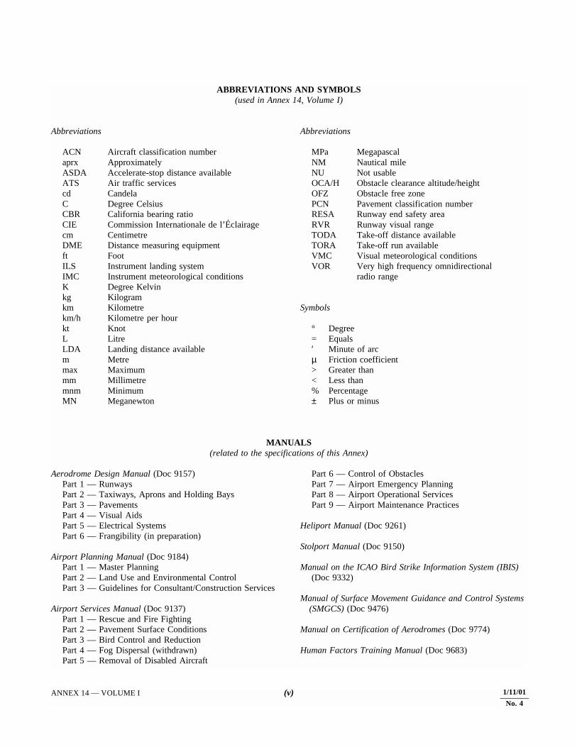
ABBREVIATIONS AND SYMBOLS(used in Annex 14, Volume I)
Abbreviations
ACN Aircraft classification numberaprx ApproximatelyASDA Accelerate-stop distance availableATS Air traffic servicescd CandelaC Degree CelsiusCBR California bearing ratioCIE Commission Internationale de l’Éclairagecm CentimetreDME Distance measuring equipmentft FootILS Instrument landing systemIMC Instrument meteorological conditionsK Degree Kelvinkg Kilogramkm Kilometrekm/h Kilometre per hourkt KnotL LitreLDA Landing distance availablem Metremax Maximummm Millimetremnm MinimumMN Meganewton
Abbreviations
MPa MegapascalNM Nautical mileNU Not usableOCA/H Obstacle clearance altitude/heightOFZ Obstacle free zonePCN Pavement classification numberRESA Runway end safety areaRVR Runway visual rangeTODA Take-off distance availableTORA Take-off run availableVMC Visual meteorological conditionsVOR Very high frequency omnidirectional
radio range
Symbols
° Degree= Equals′ Minute of arcµ Friction coefficient> Greater than< Less than% Percentage± Plus or minus
MANUALS(related to the specifications of this Annex)
Aerodrome Design Manual (Doc 9157)Part 1 — RunwaysPart 2 — Taxiways, Aprons and Holding BaysPart 3 — PavementsPart 4 — Visual AidsPart 5 — Electrical SystemsPart 6 — Frangibility (in preparation)
Airport Planning Manual (Doc 9184)Part 1 — Master PlanningPart 2 — Land Use and Environmental ControlPart 3 — Guidelines for Consultant/Construction Services
Airport Services Manual (Doc 9137)Part 1 — Rescue and Fire FightingPart 2 — Pavement Surface ConditionsPart 3 — Bird Control and ReductionPart 4 — Fog Dispersal (withdrawn)Part 5 — Removal of Disabled Aircraft
Part 6 — Control of ObstaclesPart 7 — Airport Emergency PlanningPart 8 — Airport Operational ServicesPart 9 — Airport Maintenance Practices
Heliport Manual (Doc 9261)
Stolport Manual (Doc 9150)
Manual on the ICAO Bird Strike Information System (IBIS)(Doc 9332)
Manual of Surface Movement Guidance and Control Systems (SMGCS) (Doc 9476)
Manual on Certification of Aerodromes (Doc 9774)
Human Factors Training Manual (Doc 9683)
1/11/01
No. 4
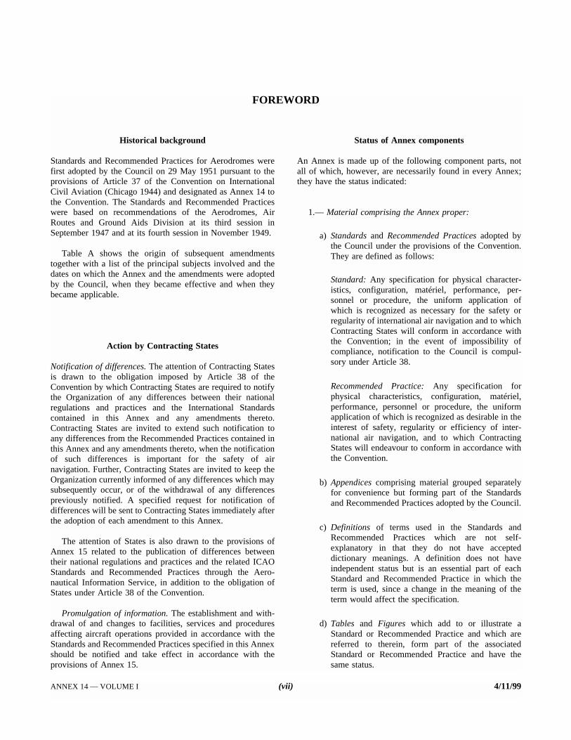
FOREWORD
Historical background
Standards and Recommended Practices for Aerodromes werefirst adopted by the Council on 29 May 1951 pursuant to theprovisions of Article 37 of the Convention on InternationalCivil Aviation (Chicago 1944) and designated as Annex 14 tothe Convention. The Standards and Recommended Practiceswere based on recommendations of the Aerodromes, AirRoutes and Ground Aids Division at its third session inSeptember 1947 and at its fourth session in November 1949.
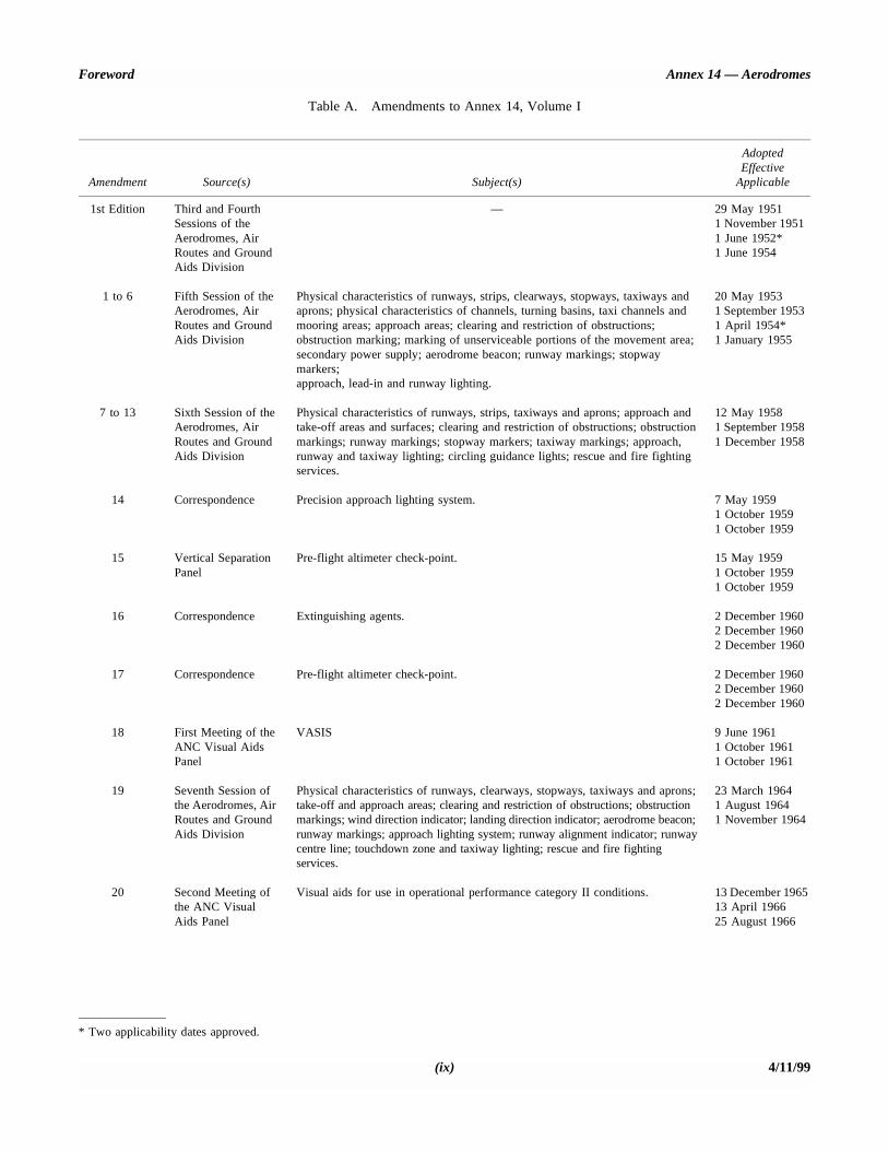
Table A shows the origin of subsequent amendmentstogether with a list of the principal subjects involved and thedates on which the Annex and the amendments were adoptedby the Council, when they became effective and when theybecame applicable.
Action by Contracting States
Notification of differences. The attention of Contracting Statesis drawn to the obligation imposed by Article 38 of theConvention by which Contracting States are required to notifythe Organization of any differences between their nationalregulations and practices and the International Standardscontained in this Annex and any amendments thereto.Contracting States are invited to extend such notification toany differences from the Recommended Practices contained inthis Annex and any amendments thereto, when the notificationof such differences is important for the safety of airnavigation. Further, Contracting States are invited to keep theOrganization currently informed of any differences which maysubsequently occur, or of the withdrawal of any differencespreviously notified. A specified request for notification ofdifferences will be sent to Contracting States immediately afterthe adoption of each amendment to this Annex.
The attention of States is also drawn to the provisions ofAnnex 15 related to the publication of differences betweentheir national regulations and practices and the related ICAOStandards and Recommended Practices through the Aero-nautical Information Service, in addition to the obligation ofStates under Article 38 of the Convention.
Promulgation of information. The establishment and with-drawal of and changes to facilities, services and proceduresaffecting aircraft operations provided in accordance with theStandards and Recommended Practices specified in this Annexshould be notified and take effect in accordance with theprovisions of Annex 15.
Status of Annex components
An Annex is made up of the following component parts, notall of which, however, are necessarily found in every Annex;they have the status indicated:
1.— Material comprising the Annex proper:
a) Standards and Recommended Practices adopted bythe Council under the provisions of the Convention.They are defined as follows:
Standard: Any specification for physical character-istics, configuration, matériel, performance, per-sonnel or procedure, the uniform application ofwhich is recognized as necessary for the safety orregularity of international air navigation and to whichContracting States will conform in accordance withthe Convention; in the event of impossibility ofcompliance, notification to the Council is compul-sory under Article 38.
Recommended Practice: Any specification forphysical characteristics, configuration, matériel,performance, personnel or procedure, the uniformapplication of which is recognized as desirable in theinterest of safety, regularity or efficiency of inter-national air navigation, and to which ContractingStates will endeavour to conform in accordance withthe Convention.
b) Appendices comprising material grouped separatelyfor convenience but forming part of the Standardsand Recommended Practices adopted by the Council.
c) Definitions of terms used in the Standards andRecommended Practices which are not self-explanatory in that they do not have accepteddictionary meanings. A definition does not haveindependent status but is an essential part of eachStandard and Recommended Practice in which theterm is used, since a change in the meaning of theterm would affect the specification.
d) Tables and Figures which add to or illustrate aStandard or Recommended Practice and which arereferred to therein, form part of the associatedStandard or Recommended Practice and have thesame status.
ANNEX 14 — VOLUME I (vii) 4/11/99
Annex 14 — Aerodromes Volume I
2.— Material approved by the Council for publication inassociation with the Standards and Recommended Practices:
a) Forewords comprising historical and explanatorymaterial based on the action of the Council andincluding an explanation of the obligations of Stateswith regard to the application of the Standards andRecommended Practices ensuing from the Conven-tion and the Resolution of Adoption.
b) Introductions comprising explanatory material intro-duced at the beginning of parts, chapters or sectionsof the Annex to assist in the understanding of theapplication of the text.
c) Notes included in the text, where appropriate, to givefactual information or references bearing on theStandards or Recommended Practices in question,but not constituting part of the Standards or Rec-ommended Practices.
d) Attachments comprising material supplementary tothe Standards and Recommended Practices, orincluded as a guide to their application.
Selection of language
This Annex has been adopted in five languages — English,Arabic, French, Russian and Spanish. Each Contracting Stateis requested to select one of those texts for the purpose ofnational implementation and for other effects provided for in
the Convention, either through direct use or throughtranslation into its own national language, and to notify theOrganization accordingly.
Editorial practices
The following practice has been adhered to in order to indicateat a glance the status of each statement: Standards have beenprinted in light face roman; Recommended Practices havebeen printed in light face italics, the status being indicated bythe prefix Recommendation; Notes have been printed in lightface italics, the status being indicated by the prefix Note.
The following editorial practice has been followed in thewriting of specifications: for Standards the operative verb“shall” is used, and for Recommended Practices the operativeverb “should” is used.
The units of measurement used in this document are inaccordance with the International System of Units (SI) asspecified in Annex 5 to the Convention on International CivilAviation. Where Annex 5 permits the use of non-SI alternativeunits these are shown in parentheses following the basic units.Where two sets of units are quoted it must not be assumed thatthe pairs of values are equal and interchangeable. It may,however, be inferred that an equivalent level of safety isachieved when either set of units is used exclusively.
Any reference to a portion of this document, which isidentified by a number and/or title, includes all subdivisions ofthat portion.
4/11/99 (viii)1/11/01
No. 4
Foreword Annex 14 — Aerodromes
Table A. Amendments to Annex 14, Volume I
Amendment Source(s) Subject(s)
AdoptedEffective
Applicable
1st Edition Third and Fourth Sessions of the Aerodromes, Air Routes and Ground Aids Division
— 29 May 1951 1 November 1951 1 June 1952* 1 June 1954
1 to 6 Fifth Session of the Aerodromes, Air Routes and Ground Aids Division
Physical characteristics of runways, strips, clearways, stopways, taxiways andaprons; physical characteristics of channels, turning basins, taxi channels andmooring areas; approach areas; clearing and restriction of obstructions;obstruction marking; marking of unserviceable portions of the movement area;secondary power supply; aerodrome beacon; runway markings; stopway markers;approach, lead-in and runway lighting.
20 May 1953 1 September 1953 1 April 1954* 1 January 1955
7 to 13 Sixth Session of the Aerodromes, Air Routes and Ground Aids Division
Physical characteristics of runways, strips, taxiways and aprons; approach andtake-off areas and surfaces; clearing and restriction of obstructions; obstructionmarkings; runway markings; stopway markers; taxiway markings; approach,runway and taxiway lighting; circling guidance lights; rescue and fire fightingservices.
12 May 1958 1 September 1958 1 December 1958
14 Correspondence Precision approach lighting system. 7 May 1959 1 October 1959 1 October 1959
15 Vertical Separation Panel
Pre-flight altimeter check-point. 15 May 1959 1 October 1959 1 October 1959
16 Correspondence Extinguishing agents. 2 December 1960 2 December 1960 2 December 1960
17 Correspondence Pre-flight altimeter check-point. 2 December 1960 2 December 1960 2 December 1960
18 First Meeting of the ANC Visual Aids Panel
VASIS 9 June 1961 1 October 1961 1 October 1961
19 Seventh Session of the Aerodromes, Air Routes and Ground Aids Division
Physical characteristics of runways, clearways, stopways, taxiways and aprons;take-off and approach areas; clearing and restriction of obstructions; obstructionmarkings; wind direction indicator; landing direction indicator; aerodrome beacon;runway markings; approach lighting system; runway alignment indicator; runwaycentre line; touchdown zone and taxiway lighting; rescue and fire fightingservices.
23 March 1964 1 August 1964 1 November 1964
20 Second Meeting of the ANC Visual Aids Panel
Visual aids for use in operational performance category II conditions. 13 December 1965 13 April 1966 25 August 1966
* Two applicability dates approved.
(ix) 4/11/99

Annex 14 — Aerodromes Volume I
21 Fourth Air Navigation Conference and Fourth Meeting of the ANC Visual Aids Panel
Emergency lighting; threshold marking; fixed distance marking; approach lightbeacons; taxiway centre line lighting; secondary power supply; maintenance ofaerodrome lighting and marking aids; monitoring of visual aids.
28 June 1967 28 October 1967 8 February 1968
22 Correspondence and ANC Visual Aids Panel
VOR aerodrome check-point marking and sign. 28 June 1968 28 October 1968 18 September 1969
23 Fifth Air Navigation Conference
Declared distances; strength of pavements; information on aerodrome conditions;reference code letters; runway length correction for slope; runway strips; taxiwayclearances; holding bays; taxi-holding position markings; approach lightingsystems; visual approach slope indicator systems; secondary power supply; rescueand fire fighting services; bird hazard reduction services.
23 January 1969 23 May 1969 18 September 1969
24 Fifth Meeting of the ANC Visual Aids Panel and First Meeting of the ANC Rescue and Fire Fighting Panel
Marking of unusable or unserviceable portions of the movement area; touchdownzone markings; category II holding position marking and sign; T-VASIS and AT-VASIS; runway edge lighting; exit taxiway centre line lighting; stop bars andclearance bars; emergency access roads; colour specifications for lights.
31 March 1971 6 September 1971 6 January 1972
25 ANC Visual Aids Panel
Visual approach slope guidance for long-bodied aircraft. 26 May 1971 26 September 1971 6 January 1972
26 Seventeenth Session of the Assembly and Middle East/South East Asia Regional Air Navigation Meeting
Aerodrome security; water rescue vehicles. 15 December 197115 April 1972 7 December 1971
27 ANC Visual Aids Panel and Middle East/South East Asia Regional Air Navigation Meeting
Runway centre line light colour coding; maintenance services. 20 March 1972 20 July 1972 7 December 1972
28 Secretariat and Sixth Meeting of the ANC Visual Aids Panel
Definition for snow on the ground; frangibility of light fixtures; runway centre linemarking; taxiway centre line lighting; colour specifications for lights.
11 December 1972 11 April 1973 16 August 1973
29 Council action in pursuance of Assembly Resolutions A17-10 and A18-10
Aerodrome security. 7 December 1973 7 April 1974 23 May 1974
30 Eighth Air Navigation Conference and editorial revision of the Annex
Runway shoulders and strips; runway end safety areas; aerodrome referencetemperature; clearways; holding bays; physical characteristics of taxiways;taxiway shoulders and strips; pavement strength; runway transverse slopes;runway braking action; obstacle limitation surfaces; category III runway lightingand marking; taxiway lighting; stop bars; rescue and fire fighting services;disabled aircraft removal.
3 February 1976 3 June 1976 30 December 1976
Amendment Source(s) Subject(s)
AdoptedEffective
Applicable
4/11/99 (x)

Foreword Annex 14 — Aerodromes
31 Seventh Meeting of the ANC Visual Aids Panel and Fifth Meeting of the ANC Obstacle Clearance Panel
Obstacle limitation surfaces; light intensity control; inset light temperatures;taxiway centre line lights; apron floodlighting; visual docking guidance systems;signs; maintenance of visual aids.
13 December 1976 13 April 1977 6 October 1977
32 Correspondence and ANC Visual Aids Panel
Definition of frangibility; siting and construction of equipment and installations onoperational areas; colour specifications for lights and markings.
14 December 1977 14 April 1978 10 August 1978
33 Correspondence and Secretariat
Reporting of information on visual approach slope indicator systems; runway,taxiway and taxi-holding position markings; approach lighting for displacedthresholds; runway edge and centre line lights; aerodrome emergency planning.
26 March 1979 26 July 1979 29 November 1979
34 Eighth Meeting of the ANC Visual Aids Panel
Apron markings; precision approach lighting systems; visual approach slopeindicator systems; circling guidance lights; runway lead-in lighting systems; stopbars; visual docking guidance system; aircraft stand manoeuvring guidance lights;aircraft stand identification signs; marking and lighting of obstacles.
30 November 1979 30 March 1980 27 November 1980
35 Secretariat and the ANC Visual Aids Panel
Reporting of pavement strength; visual approach slope indicator systems;approach lighting systems; maintenance of lighting.
23 March 1981 23 July 1981 26 November 1981
36 Aerodromes, Air Routes and Ground Aids Divisional Meeting (1981), Ninth Meeting of the ANC Visual Aids Panel and Secretariat
Aerodrome reference code; runway friction characteristics; runway end safetyareas; taxiway separation distances; rapid exit taxiways; taxiways on bridges;holding bays; obstacle limitation surfaces; PAPI; taxi-holding position markingand lights; runway centre line guidance; visual ground signals; rescue and firefighting; apron management service; declared distances; ground servicing ofaircraft; units of measure.
22 November 1982 23 March 1983 24 November 1983
37 Secretariat Fuelling. 29 March 1983 29 July 1983 24 November 1983
38 Secretariat and the ANC Visual Aids Panel
Aerodrome data; APAPI; colour coding of exit taxiway centre line lights; stopbars; taxi-holding position lights; taxiway edge markers; markers for overheadwires; obstacle lighting of lighthouses; maintenance of taxiway centre line lights;surface marking colours.
17 March 1986 27 July 1986 20 November 1986
39(Annex 14,Volume I,
1st Edition)
Secretariat and the ANC Visual Aids Panel
1. Annex to be issued in two volumes as follows: Volume I — AerodromeDesign and Operations (incorporating provisions in the eighth edition of Annex 14 as amended by Amendment 39) and Volume II — Heliports.
2. Take-off runways; aerodrome reference code; reporting of pavement strength;runway friction characteristics; conditions of movement area; separation ofparallel runways; taxiway minimum separation distances; taxi-holding positionmarking; installation tolerances for PAPI; obstacle protection surface; stop bars;signs; taxiway centre line markers; aerodrome security; surface movementguidance and control; aerodrome emergency planning; rescue and fire fighting;maintenance; runway pavement overlay; bird hazard reduction; apronmanagement service; colours for transilluminated signs and panels; aeronauticalground light characteristics.
9 March 1990 30 July 1990 15 November 1990
Amendment Source(s) Subject(s)
AdoptedEffective
Applicable
(xi) 4/11/99

Annex 14 — Aerodromes Volume I
1(Annex 14,Volume I,
2nd Edition)
Twelfth Meeting of the ANC Visual Aids Panel and Secretariat
Definitions of frangible object, precision approach runways, road, road-holdingposition, runway guard lights, and taxi-holding position; standard geodeticreference system; radio altimeter operating area, minimum distance betweenparallel runways; frangibility; runway and taxiway markings, aeronauticalbeacons, lighting aids for MLS operations, deletion of specifications on VASIS(AVASIS) and 3-BAR VASIS (3-BAR AVASIS), stop bars, runway guard lights,visual docking guidance system, taxiing guidance signs; obstacle lighting; visualaids for denoting restricted use areas; secondary power supply, electrical systems,monitoring, airport design, surface movement guidance and control systems;rescue and fire fighting, maintenance of visual aids; aeronautical ground lightcharacteristics; form and proportions of information marking; design of taxiingguidance signs; friction characteristics of wet runways.
13 March 199524 July 19959 November 1995
2 Air NavigationCommission
Aeronautical data bases and vertical component of the World Geodetic System — 1984 (WGS-84).
20 March 199721 July 19976 November 1997
3(Annex 14,Volume I,
3rd Edition)
Thirteenth Meeting of the ANC Visual Aids Panel and Secretariat
Definitions of aerodrome traffic density, de/anti-icing facility, de/anti-icing pad,holdover time, Human Factors principles, human performance, intermediate holding position, runway-holding position, signs, switch-over time; new aerodrome reference code letter F in Table1-1; runways, taxiways and taxiwayminimum separation distances related to code letter F aeroplane operations, sightdistance, runway strips, runway end safety areas, clearways, stopways, taxiways on bridges, holding bays, runway-holding positions, intermediate holding positions and road holding positions, de/anti-icing facilities; obstacle-free zone width for code letter F; runway-holding position marking, intermediate holding position marking, mandatory instruction marking, marking of de/anti-icing facilities, approach lighting systems, runway and taxiway centre line lights, stop bars, intermediate holding position lights, lighting of de/anti-icing facilities, runway guard lights, variable message signs, intersection take-off signs; visual aids for denoting obstacles; secondary power supply switch-over time, security measures in airport design, frangibility of non-visual aids on operational areas; Human Factors principles applied to aerodrome emergency planning, rescue and fire fighting, and maintenance, system of preventive maintenance for precision approach runways, categories II and III; colour measurement of aeronautical ground lights; isocandela diagrams for high-intensity taxiway centre line lights and runway guard lights; measurement of the average luminance of a sign, Table 4.1 of Appendix 4; Appendix 6.
5 March 199919 July 19994 November 1999
4 Secretariat and the Twelfth Meeting of the ANC Obstacle Clearance Panel
Definitions of aerodrome certificate, certified aerodrome, safety management system; certification of aerodromes; obstacle limitation surfaces; specifications concerning aerodrome emergency planning; rescue and fire fighting.
12 March 200116 July 20011 November 2001
Amendment Source(s) Subject(s)
AdoptedEffective
Applicable
4/11/99 (xii)1/11/01
No. 4

INTERNATIONAL STANDARDSAND RECOMMENDED PRACTICES
CHAPTER 1. GENERAL
Introductory Note.— This Annex contains Standards andRecommended Practices (specifications) that prescribe thephysical characteristics and obstacle limitation surfaces to beprovided for at aerodromes, and certain facilities and tech-nical services normally provided at an aerodrome. It is notintended that these specifications limit or regulate theoperation of an aircraft.
To a great extent, the specifications for individual facilitiesdetailed in Annex 14, Volume I, have been interrelated by areference code system, described in this chapter, and by thedesignation of the type of runway for which they are to beprovided, as specified in the definitions. This not onlysimplifies the reading of Volume I of this Annex, but in mostcases, provides for efficiently proportioned aerodromes whenthe specifications are followed.
This document sets forth the minimum aerodrome specifi-cations for aircraft which have the characteristics of thosewhich are currently operating or for similar aircraft that areplanned for introduction. Accordingly, any additional safe-guards that might be considered appropriate to provide formore demanding aircraft are not taken into account. Suchmatters are left to appropriate authorities to evaluate and takeinto account as necessary for each particular aerodrome.Guidance on some possible effects of future aircraft on thesespecifications is given in the Aerodrome Design Manual,Part 2.
It is to be noted that the specifications for precision approachrunways categories II and III are only applicable to runwaysintended to be used by aeroplanes in code numbers 3 and 4.
Annex 14, Volume I, does not include specificationsrelating to the overall planning of aerodromes (such asseparation between adjacent aerodromes or capacity ofindividual aerodromes) or to economic and other non-technical factors that need to be considered in thedevelopment of an aerodrome. Information on these subjects isincluded in the Airport Planning Manual, Part 1.
Aviation security is an integral part of aerodrome planningand operations. Annex 14, Volume I, contains severalspecifications aimed at enhancing the level of security ataerodromes. Specifications on other facilities related tosecurity are given in Annex 17 and detailed guidance on thesubject is contained in the ICAO Security Manual.
1.1 Definitions
When the following terms are used in this Annex they have thefollowing meanings:
Accuracy. A degree of conformance between the estimated ormeasured value and the true value.
Note.— For measured positional data, the accuracy isnormally expressed in terms of a distance from a statedposition within which there is a defined confidence of the trueposition falling.
Aerodrome. A defined area on land or water (including anybuildings, installations, and equipment) intended to be usedeither wholly or in part for the arrival, departure andsurface movement of aircraft.
Aerodrome beacon. Aeronautical beacon used to indicate thelocation of an aerodrome from the air.
Aerodrome certificate. A certificate issued by the appropriateauthority under applicable regulations for the operation ofan aerodrome.
Aerodrome elevation. The elevation of the highest point of thelanding area.
Aerodrome identification sign. A sign placed on an aero-drome to aid in identifying the aerodrome from the air.
Aerodrome reference point. The designated geographicallocation of an aerodrome.
Aerodrome traffic density.
a) Light. Where the number of movements in the meanbusy hour is not greater than 15 per runway or typicallyless than 20 total aerodrome movements.
b) Medium. Where the number of movements in the meanbusy hour is of the order of 16 to 25 per runway ortypically between 20 to 35 total aerodrome movements.
c) Heavy. Where the number of movements in the meanbusy hour is of the order of 26 or more per runway ortypically more than 35 total aerodrome movements.
ANNEX 14 — VOLUME I 1 4/11/991/11/01
No. 4

Annex 14 — Aerodromes Volume I
Note 1.— The number of movements in the mean busy houris the arithmetic mean over the year of the number ofmovements in the daily busiest hour.
Note 2.— Either a take-off or a landing constitutes amovement.
Aeronautical beacon. An aeronautical ground light visibleat all azimuths, either continuously or intermittently, todesignate a particular point on the surface of the earth.
Aeronautical ground light. Any light specially provided as anaid to air navigation, other than a light displayed on anaircraft.
Aeroplane reference field length. The minimum field lengthrequired for take-off at maximum certificated take-offmass, sea level, standard atmospheric conditions, still airand zero runway slope, as shown in the appropriateaeroplane flight manual prescribed by the certificatingauthority or equivalent data from the aeroplane manufac-turer. Field length means balanced field length foraeroplanes, if applicable, or take-off distance in other cases.
Note.— Attachment A, Section 2 provides information onthe concept of balanced field length and the AirworthinessManual (Doc 9760) contains detailed guidance on mattersrelated to take-off distance.
Aircraft classification number (ACN). A number expressingthe relative effect of an aircraft on a pavement for aspecified standard subgrade category.
Note.— The aircraft classification number is calculatedwith respect to the center of gravity (CG) position which yieldsthe critical loading on the critical gear. Normally the aftmostCG position appropriate to the maximum gross apron (ramp)mass is used to calculate the ACN. In exceptional cases theforwardmost CG position may result in the nose gear loadingbeing more critical.
Aircraft stand. A designated area on an apron intended to beused for parking an aircraft.
Apron. A defined area, on a land aerodrome, intended toaccommodate aircraft for purposes of loading or unloadingpassengers, mail or cargo, fuelling, parking or maintenance.
Apron management service. A service provided to regulatethe activities and the movement of aircraft and vehicles onan apron.
Barrette. Three or more aeronautical ground lights closelyspaced in a transverse line so that from a distance theyappear as a short bar of light.
Capacitor discharge light. A lamp in which high-intensityflashes of extremely short duration are produced by the
discharge of electricity at high voltage through a gasenclosed in a tube.
Certified aerodrome. An aerodrome whose operator has beengranted an aerodrome certificate.
Clearway. A defined rectangular area on the ground or waterunder the control of the appropriate authority, selected orprepared as a suitable area over which an aeroplane maymake a portion of its initial climb to a specified height.
Cyclic redundancy check (CRC). A mathematical algorithmapplied to the digital expression of data that provides alevel of assurance against loss or alteration of data.
Data quality. A degree or level of confidence that the dataprovided meet the requirements of the data user in terms ofaccuracy, resolution and integrity.
De-icing/anti-icing facility. A facility where frost, ice or snowis removed (de-icing) from the aeroplane to provide cleansurfaces, and/or where clean surfaces of the aeroplanereceive protection (anti-icing) against the formation of frostor ice and accumulation of snow or slush for a limitedperiod of time.
Note.— Further guidance is given in the Manual of AircraftGround De-icing/Anti-icing Operations (Doc 9640).
De-icing/anti-icing pad. An area comprising an inner area forthe parking of an aeroplane to receive de-icing/anti-icingtreatment and an outer area for the manoeuvring of two ormore mobile de-icing/anti-icing equipment.
Declared distances.
a) Take-off run available (TORA). The length of runwaydeclared available and suitable for the ground run of anaeroplane taking off.
b) Take-off distance available (TODA). The length of thetake-off run available plus the length of the clearway, ifprovided.
c) Accelerate-stop distance available (ASDA). The lengthof the take-off run available plus the length of thestopway, if provided.
d) Landing distance available (LDA). The length ofrunway which is declared available and suitable for theground run of an aeroplane landing.
Dependent parallel approaches. Simultaneous approaches toparallel or near-parallel instrument runways where radarseparation minima between aircraft on adjacent extendedrunway centre lines are prescribed.
Displaced threshold. A threshold not located at the extremityof a runway.
4/11/99 21/11/01
No. 4

Chapter 1 Annex 14 — Aerodromes
Effective intensity. The effective intensity of a flashing light isequal to the intensity of a fixed light of the same colourwhich will produce the same visual range under identicalconditions of observation.
Ellipsoid height (Geodetic height). The height related to thereference ellipsoid, measured along the ellipsoidal outernormal through the point in question.
Fixed light. A light having constant luminous intensity whenobserved from a fixed point.
Frangible object. An object of low mass designed to break,distort or yield on impact so as to present the minimumhazard to aircraft.
Note.— Guidance on design for frangibility is contained inthe Aerodrome Design Manual, Part 6 (in preparation).
Geodetic datum. A minimum set of parameters required todefine location and orientation of the local reference systemwith respect to the global reference system/frame.
Geoid. The equipotential surface in the gravity field of theEarth which coincides with the undisturbed mean sea level(MSL) extended continuously through the continents.
Note.— The geoid is irregular in shape because of localgravitational disturbances (wind tides, salinity, current, etc.)and the direction of gravity is perpendicular to the geoid atevery point.
Geoid undulation. The distance of the geoid above (positive)or below (negative) the mathematical reference ellipsoid.
Note.— In respect to the World Geodetic System — 1984(WGS-84) defined ellipsoid, the difference between the WGS-84 ellipsoidal height and orthometric height representsWGS-84 geoid undulation.
Hazard beacon. An aeronautical beacon used to designate adanger to air navigation.
Heliport. An aerodrome or a defined area on a structureintended to be used wholly or in part for the arrival,departure and surface movement of helicopters.
Holding bay. A defined area where aircraft can be held, orbypassed, to facilitate efficient surface movement ofaircraft.
Holdover time. The estimated time the anti-icing fluid(treatment) will prevent the formation of ice and frost andthe accumulation of snow on the protected (treated)surfaces of an aeroplane.
Human Factors principles. Principles which apply toaeronautical design, certification, training, operations and
maintenance and which seek safe interface between thehuman and other system components by proper consider-ation to human performance.
Human performance. Human capabilities and limitationswhich have an impact on the safety and efficiency ofaeronautical operations.
Identification beacon. An aeronautical beacon emitting acoded signal by means of which a particular point ofreference can be identified.
Independent parallel approaches. Simultaneous approaches toparallel or near-parallel instrument runways where radarseparation minima between aircraft on adjacent extendedrunway centre lines are not prescribed.
Independent parallel departures. Simultaneous departuresfrom parallel or near-parallel instrument runways.
Instrument runway. One of the following types of runwaysintended for the operation of aircraft using instrumentapproach procedures:
a) Non-precision approach runway. An instrument runwayserved by visual aids and a non-visual aid providing atleast directional guidance adequate for a straight-inapproach.
b) Precision approach runway, category I. An instrumentrunway served by ILS and/or MLS and visual aidsintended for operations with a decision height not lowerthan 60 m (200 ft) and either a visibility not less than800 m or a runway visual range not less than 550 m.
c) Precision approach runway, category II. An instrumentrunway served by ILS and/or MLS and visual aidsintended for operations with a decision height lowerthan 60 m (200 ft) but not lower than 30 m (100 ft) anda runway visual range not less than 350 m.
d) Precision approach runway, category III. An instrumentrunway served by ILS and/or MLS to and along thesurface of the runway and:
A — intended for operations with a decision heightlower than 30 m (100 ft), or no decision heightand a runway visual range not less than 200 m.
B — intended for operations with a decision heightlower than 15 m (50 ft), or no decision height anda runway visual range less than 200 m but not lessthan 50 m.
C — intended for operations with no decision heightand no runway visual range limitations.
Note 1.— See Annex 10, Volume I, Part I, for related ILSand/or MLS specifications.
3 4/11/991/11/01
No. 4
Annex 14 — Aerodromes Volume I
Note 2.— Visual aids need not necessarily be matched tothe scale of non-visual aids provided. The criterion for theselection of visual aids is the conditions in which operationsare intended to be conducted.
Integrity (aeronautical data). A degree of assurance that anaeronautical data and its value has not been lost nor alteredsince the data origination or authorized amendment.
Intermediate holding position. A designated position intendedfor traffic control at which taxiing aircraft and vehiclesshall stop and hold until further cleared to proceed, when soinstructed by the aerodrome control tower.
Landing area. That part of a movement area intended for thelanding or take-off of aircraft.
Landing direction indicator. A device to indicate visually thedirection currently designated for landing and for take-off.
Lighting system reliability. The probability that the completeinstallation operates within the specified tolerances and thatthe system is operationally usable.
Manoeuvring area. That part of an aerodrome to be used forthe take-off, landing and taxiing of aircraft, excludingaprons.
Marker. An object displayed above ground level in order toindicate an obstacle or delineate a boundary.
Marking. A symbol or group of symbols displayed on thesurface of the movement area in order to convey aero-nautical information.
Movement area. That part of an aerodrome to be used for thetake-off, landing and taxiing of aircraft, consisting of themanoeuvring area and the apron(s).
Near-parallel runways. Non-intersecting runways whoseextended centre lines have an angle of convergence/divergence of 15 degrees or less.
Non-instrument runway. A runway intended for the operationof aircraft using visual approach procedures.
Obstacle. All fixed (whether temporary or permanent) andmobile objects, or parts thereof, that are located on an areaintended for the surface movement of aircraft or that extendabove a defined surface intended to protect aircraft inflight.
Obstacle free zone (OFZ). The airspace above the innerapproach surface, inner transitional surfaces, and balkedlanding surface and that portion of the strip bounded bythese surfaces, which is not penetrated by any fixedobstacle other than a low-mass and frangibly mounted onerequired for air navigation purposes.
Orthometric height. Height of a point related to the geoid,generally presented as an MSL elevation.
Pavement classification number (PCN). A number expressingthe bearing strength of a pavement for unrestrictedoperations.
Precision approach runway, see Instrument runway.
Primary runway(s). Runway(s) used in preference to otherswhenever conditions permit.
Road. An established surface route on the movement areameant for the exclusive use of vehicles.
Road-holding position. A designated position at whichvehicles may be required to hold.
Runway. A defined rectangular area on a land aerodromeprepared for the landing and take-off of aircraft.
Runway end safety area (RESA). An area symmetrical aboutthe extended runway centre line and adjacent to the end ofthe strip primarily intended to reduce the risk of damage toan aeroplane undershooting or overrunning the runway.
Runway guard lights. A light system intended to cautionpilots or vehicle drivers that they are about to enter anactive runway.
Runway-holding position. A designated position intended toprotect a runway, an obstacle limitation surface, or an ILS/MLS critical/sensitive area at which taxiing aircraft andvehicles shall stop and hold, unless otherwise authorized bythe aerodrome control tower.
Runway strip. A defined area including the runway andstopway, if provided, intended:
a) to reduce the risk of damage to aircraft running off arunway; and
b) to protect aircraft flying over it during take-off orlanding operations.
Runway visual range (RVR). The range over which the pilotof an aircraft on the centre line of a runway can see therunway surface markings or the lights delineating therunway or identifying its centre line.
Safety management system. A system for the management ofsafety at aerodromes, including the organizational structure,responsibilities, procedures, processes and provisions forthe implementation of aerodrome safety policies by anaerodrome operator, which provides for control of safety at,and the safe use of, the aerodrome.
Segregated parallel operations. Simultaneous operations onparallel or near-parallel instrument runways in which one
4/11/99 41/11/01
No. 4
Chapter 1 Annex 14 — Aerodromes
runway is used exclusively for approaches and the otherrunway is used exclusively for departures.
Shoulder. An area adjacent to the edge of a pavement soprepared as to provide a transition between the pavementand the adjacent surface.
Sign.
a) Fixed message sign. A sign presenting only one message.
b) Variable message sign. A sign capable of presenting severalpre-determined messages or no message, as applicable.
Signal area. An area on an aerodrome used for the display ofground signals.
Slush. Water-saturated snow which with a heel-and-toe slap-down motion against the ground will be displaced with asplatter; specific gravity: 0.5 up to 0.8.
Note.— Combinations of ice, snow and/or standing watermay, especially when rain, rain and snow, or snow is falling,produce substances with specific gravities in excess of 0.8.These substances, due to their high water/ice content, willhave a transparent rather than a cloudy appearance and, atthe higher specific gravities, will be readily distinguishablefrom slush.
Snow (on the ground).
a) Dry snow. Snow which can be blown if loose or, ifcompacted by hand, will fall apart again upon release;specific gravity: up to but not including 0.35.
b) Wet snow. Snow which, if compacted by hand, will sticktogether and tend to or form a snowball; specificgravity: 0.35 up to but not including 0.5.
c) Compacted snow. Snow which has been compressedinto a solid mass that resists further compression andwill hold together or break up into lumps if picked up;specific gravity: 0.5 and over.
Station declination. An alignment variation between the zerodegree radial of a VOR and true north, determined at thetime the VOR station is calibrated.
Stopway. A defined rectangular area on the ground at the end oftake-off run available prepared as a suitable area in which anaircraft can be stopped in the case of an abandoned take-off.
Switch-over time (light). The time required for the actualintensity of a light measured in a given direction to fallfrom 50 per cent and recover to 50 per cent during a powersupply changeover, when the light is being operated atintensities of 25 per cent or above.
Take-off runway. A runway intended for take-off only.
Taxiway. A defined path on a land aerodrome established forthe taxiing of aircraft and intended to provide a linkbetween one part of the aerodrome and another, including:
a) Aircraft stand taxilane. A portion of an apron designatedas a taxiway and intended to provide access to aircraftstands only.
b) Apron taxiway. A portion of a taxiway system locatedon an apron and intended to provide a through taxi routeacross the apron.
c) Rapid exit taxiway. A taxiway connected to a runway atan acute angle and designed to allow landing aeroplanesto turn off at higher speeds than are achieved on otherexit taxiways thereby minimizing runway occupancytimes.
Taxiway intersection. A junction of two or more taxiways.
Taxiway strip. An area including a taxiway intended to protectan aircraft operating on the taxiway and to reduce the riskof damage to an aircraft accidentally running off thetaxiway.
Threshold. The beginning of that portion of the runway usablefor landing.
Touchdown zone. The portion of a runway, beyond thethreshold, where it is intended landing aeroplanes firstcontact the runway.
Usability factor. The percentage of time during which the useof a runway or system of runways is not restricted becauseof the cross-wind component.
Note.— Cross-wind component means the surface windcomponent at right angles to the runway centre line.
1.2 Applicability
1.2.1 The interpretation of some of the specifications inthe Annex expressly requires the exercising of discretion, thetaking of a decision or the performance of a function by theappropriate authority. In other specifications, the expressionappropriate authority does not actually appear although itsinclusion is implied. In both cases, the responsibility for what-ever determination or action is necessary shall rest with theState having jurisdiction over the aerodrome.
1.2.2 The specifications, unless otherwise indicated in aparticular context, shall apply to all aerodromes open to publicuse in accordance with the requirements of Article 15 of theConvention. The specifications of Annex 14, Volume I,Chapter 3 shall apply only to land aerodromes. The specifi-cations in this volume shall apply, where appropriate, toheliports but shall not apply to stolports.
5 4/11/991/11/01
No. 4
Annex 14 — Aerodromes Volume I
Note.— Although there are at present no specificationsrelating to stolports, it is intended that specifications for theseaerodromes will be included as they are developed. In theinterim, guidance material on stolports is given in the StolportManual.
1.2.3 Wherever a colour is referred to in this Annex, thespecifications for that colour given in Appendix 1 shall apply.
1.3 Certification of Aerodromes
Note.— The intent of these specifications is to ensure theestablishment of a regulatory regime so that compliance withthe specifications in this Annex can be effectively enforced. Itis recognized that the methods of ownership, operation andsurveillance of aerodromes differ among States. The mosteffective and transparent means of ensuring compliance withapplicable specifications is the availability of a separate safetyoversight entity and a well-defined safety oversight mechanismwith support of appropriate legislation to be able to carry outthe function of safety regulation of aerodromes.
1.3.1 As of 27 November 2003, States shall certifyaerodromes used for international operations in accordancewith the specifications contained in this Annex as well as otherrelevant ICAO specifications through an appropriate regulatoryframework.
1.3.2 Recommendation.— States should certify aero-dromes open to public use in accordance with thesespecifications as well as other relevant ICAO specificationsthrough an appropriate regulatory framework.
1.3.3 The regulatory framework shall include theestablishment of criteria for the certification of aerodromes.
Note.— Guidance on a regulatory framework is given in theManual on Certification of Aerodromes.
1.3.4 Recommendation.— A certified aerodrome shouldhave in operation a safety management system.
Note.— The intent of a safety management system is to havein place an organized and orderly approach in themanagement of aerodrome safety by the aerodrome operator.Guidance on an aerodrome safety management system is givenin the Manual on Certification of Aerodromes.
1.3.5 Recommendation.— As part of the certificationprocess, States should ensure that an aerodrome manual whichwill include all pertinent information on the aerodrome site,facilities, services, equipment, operating procedures,organization and management including a safety managementsystem, is submitted by the applicant for approval/acceptanceprior to granting the aerodrome certificate.
1.3.6 As of 24 November 2005, a certified aerodromeshall have in operation a safety management system.
1.4 Reference code
Introductory Note.— The intent of the reference code is toprovide a simple method for interrelating the numerousspecifications concerning the characteristics of aerodromes soas to provide a series of aerodrome facilities that are suitablefor the aeroplanes that are intended to operate at the aero-drome. The code is not intended to be used for determiningrunway length or pavement strength requirements. The code iscomposed of two elements which are related to the aeroplaneperformance characteristics and dimensions. Element 1 is anumber based on the aeroplane reference field length andelement 2 is a letter based on the aeroplane wing span andouter main gear wheel span. A particular specification isrelated to the more appropriate of the two elements of the codeor to an appropriate combination of the two code elements. Thecode letter or number within an element selected for designpurposes is related to the critical aeroplane characteristics forwhich the facility is provided. When applying Annex 14,Volume I, the aeroplanes which the aerodrome is intended toserve are first identified and then the two elements of the code.
1.4.1 An aerodrome reference code — code number andletter — which is selected for aerodrome planning purposesshall be determined in accordance with the characteristics ofthe aeroplane for which an aerodrome facility is intended.
1.4.2 The aerodrome reference code numbers and lettersshall have the meanings assigned to them in Table 1-1.
1.4.3 The code number for element 1 shall be determinedfrom Table 1-1, column 1, selecting the code numbercorresponding to the highest value of the aeroplane referencefield lengths of the aeroplanes for which the runway isintended.
Note.— The determination of the aeroplane reference fieldlength is solely for the selection of a code number and is notintended to influence the actual runway length provided.
1.4.4 The code letter for element 2 shall be determinedfrom Table 1-1, column 3, by selecting the code letter whichcorresponds to the greatest wing span, or the greatest outermain gear wheel span, whichever gives the more demandingcode letter of the aeroplanes for which the facility isintended.
Note.— Guidance to assist the appropriate authority indetermining the aerodrome reference code is given in theAerodrome Design Manual, Parts 1 and 2.
4/11/99 61/11/01
No. 4

Chapter 1 Annex 14 — Aerodromes
Table 1-1. Aerodrome reference code(see 1.4.2 to 1.4.4)
Note.— Guidance on planning for aeroplanes with wing spans greater than 80 m is given in the Aerodrome Design Manual,Parts 1 and 2.
Code element 1 Code element 2
Codenumber
(1)
Aeroplane referencefield length
(2)
Codeletter(3)
Wing span(4)
Outer main gearwheel spana
(5)
1 Less than 800 m A Up to but notincluding 15 m
Up to but notincluding 4.5 m
2 800 m up to but notincluding 1 200 m
B 15 m up to but notincluding 24 m
4.5 m up to but notincluding 6 m
3 1 200 m up to but notincluding 1 800 m
C 24 m up to but notincluding 36 m
6 m up to but notincluding 9 m
4 1 800 m and over D 36 m up to but notincluding 52 m
9 m up to but notincluding 14 m
E 52 m up to but notincluding 65 m
9 m up to but notincluding 14 m
F 65 m up to but not including 80 m
14 m up to but not including 16 m
a. Distance between the outside edges of the main gear wheels.
7 4/11/991/11/01
No. 46A

Annex 14 — Aerodromes Volume I
THIS PAGE INTENTIONALLY LEFT BLANK
4/11/99 81/11/01
No. 46B

CHAPTER 2. AERODROME DATA
2.1 Aeronautical data
2.1.1 Determination and reporting of aerodrome relatedaeronautical data shall be in accordance with the accuracy andintegrity requirements set forth in Tables 1 to 5 contained inAppendix 5 while taking into account the established qualitysystem procedures. Accuracy requirements for aeronauticaldata are based upon a 95 per cent confidence level and in thatrespect, three types of positional data shall be identified:surveyed points (e.g. runway threshold), calculated points(mathematical calculations from the known surveyed points ofpoints in space, fixes) and declared points (e.g. flightinformation region boundary points).
Note.— Specifications governing the quality system aregiven in Annex 15, Chapter 3.
2.1.2 Contracting States shall ensure that integrity ofaeronautical data is maintained throughout the data processfrom survey/origin to the next intended user. Aeronautical dataintegrity requirements shall be based upon the potential riskresulting from the corruption of data and upon the use towhich the data item is put. Consequently, the followingclassification and data integrity level shall apply:
a) critical data, integrity level 1 × 10⁻⁸: there is a highprobability when using corrupted critical data that thecontinued safe flight and landing of an aircraft would beseverely at risk with the potential for catastrophe;
b) essential data, integrity level 1 × 10⁻⁵: there is a lowprobability when using corrupted essential data thatthe continued safe flight and landing of an aircraftwould be severely at risk with the potential forcatastrophe; and
c) routine data, integrity level 1 × 10⁻³: there is a very lowprobability when using corrupted routine data that thecontinued safe flight and landing of an aircraft would beseverely at risk with the potential for catastrophe.
2.1.3 Protection of electronic aeronautical data whilestored or in transit shall be totally monitored by the cyclicredundancy check (CRC). To achieve protection of theintegrity level of critical and essential aeronautical data asclassified in 2.1.2 above, a 32 or 24 bit CRC algorithm shallapply respectively.
2.1.4 Recommendation. — To achieve protection of theintegrity level of routine aeronautical data as classified in2.1.2 above, a 16 bit CRC algorithm should apply.
Note.— Guidance material on the aeronautical data qualityrequirements (accuracy, resolution, integrity, protection andtraceability) is contained in the World Geodetic System —1984 (WGS-84) Manual (Doc 9674). Supporting material inrespect of the provisions of Appendix 5 related to accuracyand integrity of aeronautical data, is contained in RTCADocument DO-201A and European Organization for CivilAviation Equipment (EUROCAE) Document ED-77, entitledIndustry Requirements for Aeronautical Information.
2.1.5 Geographical coordinates indicating latitude andlongitude shall be determined and reported to the aeronauticalinformation services authority in terms of the World GeodeticSystem — 1984 (WGS-84) geodetic reference datum, ident-ifying those geographical coordinates which have beentransformed into WGS-84 coordinates by mathematical meansand whose accuracy of original field work does not meet therequirements in Appendix 5, Table 1.
2.1.6 The order of accuracy of the field work shall be suchthat the resulting operational navigation data for the phases offlight will be within the maximum deviations, with respect to anappropriate reference frame, as indicated in tables contained inAppendix 5.
2.1.7 In addition to the elevation (referenced to mean sealevel) of the specific surveyed ground positions at aerodromes,geoid undulation (referenced to the WGS-84 ellipsoid) forthose positions as indicated in Appendix 5, shall be determinedand reported to the aeronautical information services authority.
Note 1.— An appropriate reference frame is that whichenables WGS-84 to be realized on a given aerodrome and withrespect to which all coordinate data are related.
Note 2.— Specifications governing the publication ofWGS-84 coordinates are given in Annex 4, Chapter 2 andAnnex 15, Chapter 3.
2.2 Aerodrome reference point
2.2.1 An aerodrome reference point shall be establishedfor an aerodrome.
2.2.2 The aerodrome reference point shall be located nearthe initial or planned geometric centre of the aerodrome andshall normally remain where first established.
2.2.3 The position of the aerodrome reference point shallbe measured and reported to the aeronautical informationservices authority in degrees, minutes and seconds.
ANNEX 14 — VOLUME I 7 4/11/99

Annex 14 — Aerodromes Volume I
2.3 Aerodrome and runway elevations
2.3.1 The aerodrome elevation and geoid undulation at theaerodrome elevation position shall be measured to the accuracyof one-half metre or foot and reported to the aeronauticalinformation services authority.
2.3.2 For an aerodrome used by international civil aviationfor non-precision approaches, the elevation and geoid un-dulation of each threshold, the elevation of the runway end andany significant high and low intermediate points along therunway shall be measured to the accuracy of one-half metre orfoot and reported to the aeronautical information servicesauthority.
2.3.3 For precision approach runway, the elevation andgeoid undulation of the threshold, the elevation of the runwayend and the highest elevation of the touchdown zone shall bemeasured to the accuracy of one-quarter metre or foot andreported to the aeronautical information services authority.
Note.— Geoid undulation must be measured in accordancewith the appropriate system of coordinates.
2.4 Aerodrome reference temperature
2.4.1 An aerodrome reference temperature shall be deter-mined for an aerodrome in degrees Celsius.
2.4.2 Recommendation.— The aerodrome reference tem-perature should be the monthly mean of the daily maximumtemperatures for the hottest month of the year (the hottest monthbeing that which has the highest monthly mean temperature).This temperature should be averaged over a period of years.
2.5 Aerodrome dimensions and related information
2.5.1 The following data shall be measured or described,as appropriate, for each facility provided on an aerodrome:
a) runway — true bearing to one-hundredth of a degree,designation number, length, width, displaced thresholdlocation to the nearest metre or foot, slope, surface type,type of runway and, for a precision approach runwaycategory I, the existence of an obstacle free zone whenprovided;
c) taxiway — designation, width, surface type;
d) apron — surface type, aircraft stands;
e) the boundaries of the air traffic control service;
f) clearway — length to the nearest metre or foot, groundprofile;
g) visual aids for approach procedures, marking and lightingof runways, taxiways and aprons, other visual guidanceand control aids on taxiways and aprons, including taxi-holding positions and stopbars, and location and type ofvisual docking guidance systems;
h) location and radio frequency of any VOR aerodromecheck-point;
i) location and designation of standard taxi-routes; and
j) distances to the nearest metre or foot of localizer andglide path elements comprising an instrument landingsystem (ILS) or azimuth and elevation antenna ofmicrowave landing system (MLS) in relation to theassociated runway extremities.
2.5.2 The geographical coordinates of each threshold shallbe measured and reported to the aeronautical informationservices authority in degrees, minutes, seconds and hundredthsof seconds.
2.5.3 The geographical coordinates of appropriate taxiwaycentre line points shall be measured and reported to theaeronautical information services authority in degrees, minutes,seconds and hundredths of seconds.
2.5.4 The geographical coordinates of each aircraft standshall be measured and reported to the aeronautical informationservices authority in degrees, minutes, seconds and hundredthsof seconds.
2.5.5 The geographical coordinates of significant obstaclesin the approach and take-off areas, in the circling area and in thevicinity of an aerodrome shall be measured and reported to theaeronautical information services authority in degrees, minutes,seconds and tenths of seconds. In addition, the top elevationrounded up to the nearest metre or foot, type, marking andlighting (if any) of the significant obstacles shall be reported tothe aeronautical information services authority.
Note.— This information may best be shown in the form ofcharts such as those required for the preparation of aero-nautical publications as specified in Annexes 4 and 15.
2.6 Strength of pavements
2.6.1 The bearing strength of a pavement shall bedetermined.
b) striprunway end safety area length, width to the neareststopway metre or foot, surface type;
4/11/99 8

Chapter 2 Annex 14 — Aerodromes
2.6.2 The bearing strength of a pavement intended foraircraft of apron (ramp) mass greater than 5 700 kg shall bemade available using the aircraft classification number —pavement classification number (ACN-PCN) method byreporting all of the following information:
a) the pavement classification number (PCN);
b) pavement type for ACN-PCN determination;
c) subgrade strength category;
d) maximum allowable tire pressure category or maximumallowable tire pressure value; and
e) evaluation method.
Note.— If necessary, PCNs may be published to an accuracyof one-tenth of a whole number.
2.6.3 The pavement classification number (PCN) reportedshall indicate that an aircraft with an aircraft classificationnumber (ACN) equal to or less than the reported PCN canoperate on the pavement subject to any limitation on the tirepressure, or aircraft all-up mass for specified aircraft type(s).
Note.— Different PCNs may be reported if the strength of thepavement is subject to significant seasonal variation.
2.6.4 The ACN of an aircraft shall be determined inaccordance with the standard procedures associated with theACN-PCN method.
Note.— The standard procedures for determining the ACNof an aircraft are given in the Aerodrome Design Manual,Part 3. For convenience several aircraft types currently in usehave been evaluated on rigid and flexible pavements founded onthe four subgrade categories in 2.6.6 b) below and the resultstabulated in that manual.
2.6.5 For the purposes of determining the ACN, thebehaviour of a pavement shall be classified as equivalent to arigid or flexible construction.
2.6.6 Information on pavement type for ACN-PCNdetermination, subgrade strength category, maximum allowabletire pressure category and evaluation method shall be reportedusing the following codes:
a) Pavement type for ACN-PCN determination:
Code
Rigid pavement RFlexible pavement F
Note.— If the actual construction is composite or non-standard, include a note to that effect (see example 2below).
b) Subgrade strength category:Code
c) Maximum allowable tire pressure category:
Code
d) Evaluation method:
Code
Note.— The following examples illustrate how pavementstrength data are reported under the ACN-PCN method.
Example 1.— If the bearing strength of a rigid pavement,resting on a medium strength subgrade, has been assessed bytechnical evaluation to be PCN 80 and there is no tire pressurelimitation, then the reported information would be:
PCN 80 / R / B / W / T
High strength: characterized by K =150 MN/m3 and representing all K valuesabove 120 MN/m3 for rigid pavements, andby CBR = 15 and representing all CBRvalues above 13 for flexible pavements.
A
Medium strength: characterized by K =80 MN/m3 and representing a range in K of60 to 120 MN/m3 for rigid pavements, andby CBR = 10 and representing a range inCBR of 8 to 13 for flexible pavements.
B
Low strength: characterized by K =40 MN/m3 and representing a range in K of25 to 60 MN/m3 for rigid pavements, andby CBR = 6 and representing a range inCBR of 4 to 8 for flexible pavements.
C
Ultra low strength: characterized by K =20 MN/m3 and representing all K valuesbelow 25 MN/m3 for rigid pavements, andby CBR = 3 and representing all CBRvalues below 4 for flexible pavements.
D
High: no pressure limit W
Medium: pressure limited to 1.50 MPa X
Low: pressure limited to 1.00 MPa Y
Very low: pressure limited to 0.50 MPa Z
Technical evaluation: representing a speci-fic study of the pavement characteristicsand application of pavement behaviourtechnology.
T
Using aircraft experience: representing aknowledge of the specific type and mass ofaircraft satisfactorily being supported underregular use.
U
9 4/11/99
Annex 14 — Aerodromes Volume I
Example 2.— If the bearing strength of a compositepavement, behaving like a flexible pavement and resting on ahigh strength subgrade, has been assessed by using aircraftexperience to be PCN 50 and the maximum tire pressureallowable is 1.00 MPa, then the reported information would be:
PCN 50 / F / A / Y / U
Note.— Composite construction.
Example 3.— If the bearing strength of a flexible pavement,resting on a medium strength subgrade, has been assessed bytechnical evaluation to be PCN 40 and the maximum allowabletire pressure is 0.80 MPa, then the reported information would be:
PCN 40 / F / B / 0.80 MPa /T
Example 4.— If a pavement is subject to a B747-400 all-upmass limitation of 390 000 kg, then the reported informationwould include the following note.
Note.— The reported PCN is subject to a B747-400 all-upmass limitation of 390 000 kg.
2.6.7 Recommendation.— Criteria should be establishedto regulate the use of a pavement by an aircraft with an ACNhigher than the PCN reported for that pavement in accordancewith 2.6.2 and 2.6.3.
Note.— Attachment A, Section 18 details a simple method forregulating overload operations while the Aerodrome DesignManual, Part 3 includes the descriptions of more detailedprocedures for evaluation of pavements and their suitability forrestricted overload operations.
2.6.8 The bearing strength of a pavement intended foraircraft of apron (ramp) mass equal to or less than 5 700 kg shallbe made available by reporting the following information:
a) maximum allowable aircraft mass; and
b) maximum allowable tire pressure.
Example: 4 000 kg/0.50 MPa.
2.7 Pre-flight altimetercheck location
2.7.1 One or more pre-flight altimeter check locationsshall be established for an aerodrome.
2.7.2 Recommendation.— A pre-flight check locationshould be located on an apron.
Note 1.— Locating a pre-flight altimeter check location onan apron enables an altimeter check to be made prior toobtaining taxi clearance and eliminates the need for stoppingfor that purpose after leaving the apron.
Note 2.— Normally an entire apron can serve as asatisfactory altimeter check location.
2.7.3 The elevation of a pre-flight altimeter check locationshall be given as the average elevation, rounded to the nearestmetre or foot, of the area on which it is located. The elevation ofany portion of a pre-flight altimeter check location shall bewithin 3 m (10 ft) of the average elevation for that location.
2.8 Declared distances
The following distances shall be calculated to the nearest metreor foot for a runway intended for use by internationalcommercial air transport:
a) take-off run available;
b) take-off distance available;
c) accelerate-stop distance available; and
d) landing distance available.
Note.— Guidance on calculation of declared distances isgiven in Attachment A, Section 3.
2.9 Condition of the movement area andrelated facilities
2.9.1 Information on the condition of the movement areaand the operational status of related facilities shall be providedto the appropriate aeronautical information service units, andsimilar information of operational significance to the air trafficservices units, to enable those units to provide the necessaryinformation to arriving and departing aircraft. The informationshall be kept up to date and changes in conditions reportedwithout delay.
2.9.2 The condition of the movement area and the oper-ational status of related facilities shall be monitored and reportson matters of operational significance or affecting aircraftperformance given, particularly in respect of the following:
a) construction or maintenance work;
b) rough or broken surfaces on a runway, a taxiway or anapron;
c) snow, slush or ice on a runway, a taxiway or an apron;
d) water on a runway, a taxiway or an apron;
e) snow banks or drifts adjacent to a runway, a taxiway or anapron;
4/11/99 10

Chapter 2 Annex 14 — Aerodromes
f) anti-icing or de-icing liquid chemicals on a runway or ataxiway;
g) other temporary hazards, including parked aircraft;
h) failure or irregular operation of part or all of theaerodrome visual aids; and
i) failure of the normal or secondary power supply.
2.9.3 Recommendation.— To facilitate compliance with2.9.1 and 2.9.2 inspections of the movement area should becarried out each day at least once where the code number is 1or 2 and at least twice where the code number is 3 or 4.
Note.— Guidance on carrying out daily inspections of themovement area is given in the Airport Services Manual, Part 8and in the Manual of Surface Movement Guidance and ControlSystems (SMGCS).
Water on a runway
2.9.4 Recommendation.— Whenever water is present ona runway, a description of the runway surface conditions on thecentre half of the width of the runway, including the possibleassessment of water depth, where applicable, should be madeavailable using the following terms:
DAMP — the surface shows a change of colour due tomoisture.
WET — the surface is soaked but there is no standing water.WATER PATCHES — significant patches of standing water
are visible.FLOODED — extensive standing water is visible.
2.9.5 Information that a runway or portion thereof may beslippery when wet shall be made available.
2.9.6 A runway or portion thereof shall be determined asbeing slippery when wet when the measurements specified in9.4.5 show that the runway surface friction characteristics asmeasured by a continuous friction measuring device are belowthe minimum friction level specified by the State.
Note.— Guidance on determining and expressing theminimum friction level is provided in Attachment A, Section 7.
2.9.7 Information on the minimum friction level specifiedby the State for reporting slippery runway conditions and thetype of friction measuring device used shall be made available.
2.9.8 Recommendation.— When it is suspected that arunway may become slippery under unusual conditions, thenadditional measurements should be made when such conditionsoccur, and information on the runway surface friction charac-teristics made available when these additional measurementsshow that the runway or a portion thereof has become slippery.
Snow, slush or ice on a runway
Note 1.— The intent of these specifications is to satisfy theSNOWTAM and NOTAM promulgation requirements containedin Annex 15.
Note 2.— Runway surface condition sensors may be used todetect and continuously display current or predicted infor-mation on surface conditions such as the presence of moisture,or imminent formation of ice on pavements.
2.9.9 Recommendation.— Whenever a runway is affectedby snow, slush or ice, and it has not been possible to clear theprecipitant fully, the condition of the runway should beassessed, and the friction coefficient measured.
Note.— Guidance on determining and expressing the frictioncharacteristics of snow- and ice-covered paved surfaces isprovided in Attachment A, Section 6.
2.9.10 Recommendation.— The readings of the frictionmeasuring device on snow-, slush-, or ice-covered surfacesshould adequately correlate with the readings of one other suchdevice.
Note.— The principal aim is to measure surface friction in amanner that is relevant to the friction experienced by an aircrafttire, thereby providing correlation between the frictionmeasuring device and aircraft braking performance.
2.9.11 Recommendation.— Whenever dry snow, wetsnow or slush is present on a runway, an assessment of the meandepth over each third of the runway should be made to anaccuracy of approximately 2 cm for dry snow, 1 cm for wet snowand 0.3 cm for slush.
2.10 Disabled aircraft removal
Note.— See 9.3 for information on disabled aircraft removalservices.
2.10.1 Recommendation.— The telephone/telex number(s)of the office of the aerodrome coordinator of operations forthe removal of an aircraft disabled on or adjacent to themovement area should be made available, on request, to aircraftoperators.
2.10.2 Recommendation.— Information concerning thecapability to remove an aircraft disabled on or adjacent to themovement area should be made available.
Note.— The capability to remove a disabled aircraft may beexpressed in terms of the largest type of aircraft which theaerodrome is equipped to remove.
11 4/11/99

Annex 14 — Aerodromes Volume I
2.11 Rescue and fire fighting
Note.— See 9.2 for information on rescue and fire fightingservices.
2.11.1 Information concerning the level of protectionprovided at an aerodrome for aircraft rescue and fire fightingpurposes shall be made available.
2.11.2 Recommendation.— The level of protectionnormally available at an aerodrome should be expressed interms of the category of the rescue and fire fighting services asdescribed in 9.2 and in accordance with the types and amountsof extinguishing agents normally available at the aerodrome.
2.11.3 Significant changes in the level of protectionnormally available at an aerodrome for rescue and fire fightingshall be notified to the appropriate air traffic services units andaeronautical information units to enable those units to providethe necessary information to arriving and departing aircraft.When such a change has been corrected, the above units shall beadvised accordingly.
Note.— A significant change in the level of protection isconsidered to be a change in the category of the rescue and firefighting service from the category normally available at theaerodrome, resulting from a change in availability ofextinguishing agents, equipment to deliver the agents orpersonnel to operate the equipment, etc.
2.11.4 Recommendation.— A significant change shouldbe expressed in terms of the new category of the rescue and firefighting service available at the aerodrome.
2.12 Visual approach slopeindicator systems
The following information concerning a visual approach slopeindicator system installation shall be made available:
a) associated runway designation number;
b) type of system according to 5.3.5.2. For an AT-VASIS,PAPI or APAPI installation, the side of the runway onwhich the lights are installed, i.e. left or right, shall begiven;
c) where the axis of the system is not parallel to the runwaycentre line, the angle of displacement and the direction ofdisplacement, i.e. left or right shall be indicated;
d) nominal approach slope angle(s). For a T-VASIS or anAT-VASIS this shall be angle θ according to the formulain Figure 5-14 and for a PAPI and an APAPI this shall beangle (B + C) ÷ 2 and (A + B) ÷ 2, respectively as inFigure 5-16; and
e) minimum eye height(s) over the threshold of the on-slopesignal(s). For a T-VASIS or an AT-VASIS this shall bethe lowest height at which only the wing bar(s) arevisible; however, the additional heights at which the wingbar(s) plus one, two or three fly down light units comeinto view may also be reported if such information wouldbe of benefit to aircraft using the approach. For a PAPIthis shall be the setting angle of the third unit from therunway minus 2′, i.e. angle B minus 2′, and for an APAPIthis shall be the setting angle of the unit farther from therunway minus 2′, i.e. angle A minus 2′.
2.13 Coordination between aeronautical informationservices and aerodrome authorities
2.13.1 To ensure that aeronautical information servicesunits obtain information to enable them to provide up-to-datepre-flight information and to meet the need for in-flightinformation, arrangements shall be made between aeronauticalinformation services and aerodrome authorities responsible foraerodrome services to report to the responsible aeronauticalinformation services unit, with a minimum of delay:
a) information on aerodrome conditions (ref. 2.9, 2.10, 2.11and 2.12 above);
b) the operational status of associated facilities, services andnavigation aids within their area of responsibility;
c) any other information considered to be of operationalsignificance.
2.13.2 Before introducing changes to the air navigationsystem, due account shall be taken by the services responsiblefor such changes of the time needed by the aeronauticalinformation service for the preparation, production and issueof relevant material for promulgation. To ensure timelyprovision of the information to the aeronautical informationservice, close coordination between those services concernedis therefore required.
2.13.3 Of a particular importance are changes toaeronautical information that affect charts and/or computer-based navigation systems which qualify to be notified by theaeronautical information regulation and control (AIRAC)system, as specified in Annex 15, Chapter 6 and Appendix 4.The predetermined, internationally agreed AIRAC effectivedates in addition to 14 days postage time shall be observed bythe responsible aerodrome services when submitting the rawinformation/data to aeronautical information services.
2.13.4 The aerodrome services responsible for theprovision of raw aeronautical information/data to theaeronautical information services shall do that while taking
4/11/99 12

Chapter 2 Annex 14 — Aerodromes
into account accuracy and integrity requirements foraeronautical data as specified in Appendix 5 to this Annex.
Note 1.— Specifications for the issue of a NOTAM andSNOWTAM are contained in Annex 15, Chapter 5, Appendices6 and 2 respectively.
Note 2.— AIRAC information is distributed by the AIS atleast 42 days in advance of the AIRAC effective dates with the
objective of reaching recipients at least 28 days in advance ofthe effective date.
Note 3.— The schedule of the predetermined internationallyagreed AIRAC common effective dates at intervals of 28 days,including 6 November 1997 and guidance for the AIRAC useare contained in the Aeronautical Information Services Manual(Doc 8126, Chapter 3, 3.1.1 and Chapter 4, 4.4).
13 4/11/99
CHAPTER 3. PHYSICAL CHARACTERISTICS
3.1 Runways
Number and orientation of runways
Introductory Note.— Many factors affect the determinationof the orientation, siting and number of runways.
One important factor is the usability factor, as determinedby the wind distribution, which is specified hereunder. Anotherimportant factor is the alignment of the runway to facilitate theprovision of approaches conforming to the approach surfacespecifications of Chapter 4. In Attachment A, Section 1, infor-mation is given concerning these and other factors.
When a new instrument runway is being located, particularattention needs to be given to areas over which aeroplaneswill be required to fly when following instrument approachand missed approach procedures, so as to ensure thatobstacles in these areas or other factors will not restrict theoperation of the aeroplanes for which the runway is intended.
3.1.1 Recommendation.— The number and orientationof runways at an aerodrome should be such that the usabilityfactor of the aerodrome is not less than 95 per cent for theaeroplanes that the aerodrome is intended to serve.
3.1.2 Choice of maximum permissiblecross-wind components
Recommendation.— In the application of 3.1.1 it shouldbe assumed that landing or take-off of aeroplanes is, in normalcircumstances, precluded when the cross-wind componentexceeds:
— 37 km/h (20 kt) in the case of aeroplanes whose refer-ence field length is 1 500 m or over, except that whenpoor runway braking action owing to an insufficientlongitudinal coefficient of friction is experienced withsome frequency, a cross-wind component not exceeding24 km/h (13 kt) should be assumed;
— 24 km/h (13 kt) in the case of aeroplanes whose refer-ence field length is 1 200 m or up to but not including1 500 m; and
— 19 km/h (10 kt) in the case of aeroplanes whose refer-ence field length is less than 1 200 m.
Note.— In Attachment A, Section 1, guidance is given onfactors affecting the calculation of the estimate of the usabilityfactor and allowances which may have to be made to takeaccount of the effect of unusual circumstances.
3.1.3 Data to be used
Recommendation.— The selection of data to be used forthe calculation of the usability factor should be based onreliable wind distribution statistics that extend over as long aperiod as possible, preferably of not less than five years. Theobservations used should be made at least eight times dailyand spaced at equal intervals of time.
Note.— These winds are mean winds. Reference to the needfor some allowance for gusty conditions is made in Attachment A,Section 1.
Location of threshold
3.1.4 Recommendation.— A threshold should normallybe located at the extremity of a runway unless operationalconsiderations justify the choice of another location.
Note.— Guidance on the siting of the threshold is given inAttachment A, Section 10.
3.1.5 Recommendation.— When it is necessary todisplace a threshold, either permanently or temporarily, fromits normal location, account should be taken of the variousfactors which may have a bearing on the location of thethreshold. Where this displacement is due to an unserviceablerunway condition, a cleared and graded area of at least 60 min length should be available between the unserviceable areaand the displaced threshold. Additional distance should alsobe provided to meet the requirements of the runway end safetyarea as appropriate.
Note.— Guidance on factors which may be considered inthe determination of the location of a displaced threshold isgiven in Attachment A, Section 10.
Actual length of runways
3.1.6 Primary runway
Recommendation.— Except as provided in 3.1.8, theactual runway length to be provided for a primary runway
ANNEX 14 — VOLUME I 14 4/11/99

Chapter 3 Annex 14 — Aerodromes
should be adequate to meet the operational requirements ofthe aeroplanes for which the runway is intended and should benot less than the longest length determined by applying thecorrections for local conditions to the operations andperformance characteristics of the relevant aeroplanes.
Note 1.— This specification does not necessarily meanproviding for operations by the critical aeroplane at itsmaximum mass.
Note 2.— Both take-off and landing requirements need tobe considered when determining the length of runway to beprovided and the need for operations to be conducted in bothdirections of the runway.
Note 3.— Local conditions that may need to be consideredinclude elevation, temperature, runway slope, humidity andthe runway surface characteristics.
Note 4.— When performance data on aeroplanes for whichthe runway is intended are not known, guidance on the deter-mination of the actual length of a primary runway by appli-cation of general correction factors is given in the AerodromeDesign Manual, Part 1.
3.1.7 Secondary runway
Recommendation.— The length of a secondary runwayshould be determined similarly to primary runways except thatit needs only to be adequate for those aeroplanes whichrequire to use that secondary runway in addition to the otherrunway or runways in order to obtain a usability factor of atleast 95 per cent.
3.1.8 Runways with stopwaysor clearways
Recommendation.— Where a runway is associated with astopway or clearway, an actual runway length less than thatresulting from application of 3.1.6 or 3.1.7, as appropriate,may be considered satisfactory, but in such a case anycombination of runway, stopway and clearway providedshould permit compliance with the operational requirementsfor take-off and landing of the aeroplanes the runway isintended to serve.
Note.— Guidance on use of stopways and clearways isgiven in Attachment A, Section 2.
Width of runways
3.1.9 Recommendation.— The width of a runway shouldbe not less than the appropriate dimension specified in thefollowing tabulation:
a. The width of a precision approach runway should be notless than 30 m where the code number is 1 or 2.
Note 1.— The combinations of code numbers and letters forwhich widths are specified have been developed for typicalaeroplane characteristics.
Note 2.— Factors affecting runway width are given in theAerodrome Design Manual, Part 1.
Minimum distance between parallel runways
3.1.10 Recommendation.— Where parallel non-instru-ment runways are intended for simultaneous use, the minimumdistance between their centre lines should be:
— 210 m where the higher code number is 3 or 4;
— 150 m where the higher code number is 2; and
— 120 m where the higher code number is 1.
Note.— Procedures for wake turbulence categorization ofaircraft and wake turbulence separation minima are containedin the Procedures for Air Navigation Services — Air TrafficManagement (PANS-ATM), Doc 4444, Part V, Section 16.
3.1.11 Recommendation.— Where parallel instrumentrunways are intended for simultaneous use subject toconditions specified in the PANS-ATM (Doc 4444) and thePANS-OPS (Doc 8168), Volume I, the minimum distancebetween their centre lines should be:
— 1 035 m for independent parallel approaches;
— 915 m for dependent parallel approaches;
— 760 m for independent parallel departures;
— 760 m for segregated parallel operations;
except that:
a) for segregated parallel operations the specifiedminimum distance:
Code letter
Code number A B C D E F
1a 18 m 18 m 23 m – – –2a 23 m 23 m 30 m – – –3 30 m 30 m 30 m 45 m – –4 – – 45 m 45 m 45 m 60 m
15 4/11/991/11/01
No. 4

Annex 14 — Aerodromes Volume I
1) may be decreased by 30 m for each 150 m that thearrival runway is staggered toward the arrivingaircraft, to a minimum of 300 m; and
2) should be increased by 30 m for each 150 m that thearrival runway is staggered away from the arrivingaircraft;
b) for independent parallel approaches, combinations ofminimum distances and associated conditions other thanthose specified in the PANS-ATM (Doc 4444) may beapplied when it is determined that such combinationswould not adversely affect the safety of aircraftoperations.
Note.— Procedures and facilities requirements forsimultaneous operations on parallel or near-parallel instru-ment runways are contained in the PANS-ATM (Doc 4444),Part IV and the PANS-OPS (Doc 8168), Volume I, Part VIIand Volume II, Parts II and III and relevant guidance iscontained in the Manual of Simultaneous Operations onParallel or Near-Parallel Instrument Runways (Doc 9643).
Slopes on runways
3.1.12 Longitudinal slopes
Recommendation.— The slope computed by dividing thedifference between the maximum and minimum elevationalong the runway centre line by the runway length should notexceed:
— 1 per cent where the code number is 3 or 4; and
— 2 per cent where the code number is 1 or 2.
3.1.13 Recommendation.— Along no portion of arunway should the longitudinal slope exceed:
— 1.25 per cent where the code number is 4, except thatfor the first and last quarter of the length of the runwaythe longitudinal slope should not exceed 0.8 per cent;
— 1.5 per cent where the code number is 3, except that forthe first and last quarter of the length of a precisionapproach runway category II or III the longitudinalslope should not exceed 0.8 per cent; and
— 2 per cent where the code number is 1 or 2.
3.1.14 Longitudinal slope changes
Recommendation.— Where slope changes cannot beavoided, a slope change between two consecutive slopesshould not exceed:
— 1.5 per cent where the code number is 3 or 4; and
— 2 per cent where the code number is 1 or 2.
Note.— Guidance on slope changes before a runway isgiven in Attachment A, Section 4.
3.1.15 Recommendation.— The transition from oneslope to another should be accomplished by a curved surfacewith a rate of change not exceeding:
— 0.1 per cent per 30 m (minimum radius of curvature of30 000 m) where the code number is 4;
— 0.2 per cent per 30 m (minimum radius of curvature of15 000 m) where the code number is 3; and
— 0.4 per cent per 30 m (minimum radius of curvature of7 500 m) where the code number is 1 or 2.
3.1.16 Sight distance
Recommendation.— Where slope changes cannot beavoided, they should be such that there will be anunobstructed line of sight from:
— any point 3 m above a runway to all other points 3 m abovethe runway within a distance of at least half the length ofthe runway where the code letter is C, D, E or F.
— any point 2 m above a runway to all other points 2 m abovethe runway within a distance of at least half the length ofthe runway where the code letter is B; and
— any point 1.5 m above a runway to all other points 1.5 mabove the runway within a distance of at least half thelength of the runway where the code letter is A.
Note.— Consideration will have to be given to providing anunobstructed line of sight over the entire length of a singlerunway where a full-length parallel taxiway is not available.Where an aerodrome has intersecting runways, additionalcriteria on the line of sight of the intersection area would needto be considered for operational safety. See the AerodromeDesign Manual, Part 1.
3.1.17 Distance between slope changes
Recommendation.— Undulations or appreciable changesin slopes located close together along a runway should beavoided. The distance between the points of intersection of twosuccessive curves should not be less than:
a) the sum of the absolute numerical values of the corre-sponding slope changes multiplied by the appropriatevalue as follows:
4/11/99 161/11/01
No. 4
Chapter 3 Annex 14 — Aerodromes
— 30 000 m where the code number is 4;
— 15 000 m where the code number is 3; and
— 5 000 m where the code number is 1 or 2; or
b) 45 m;
whichever is greater.
Note.— Guidance on implementing this specification isgiven in Attachment A, Section 4.
3.1.18 Transverse slopes
Recommendation.— To promote the most rapid drainage ofwater, the runway surface should, if practicable, be camberedexcept where a single crossfall from high to low in the directionof the wind most frequently associated with rain would ensurerapid drainage. The transverse slope should ideally be:
— 1.5 per cent where the code letter is C, D, E or F; and
— 2 per cent where the code letter is A or B;
but in any event should not exceed 1.5 per cent or 2 per cent,as applicable, nor be less than 1 per cent except at runway ortaxiway intersections where flatter slopes may be necessary.
For a cambered surface the transverse slope on each side ofthe centre line should be symmetrical.
Note.— On wet runways with cross-wind conditions theproblem of aquaplaning from poor drainage is apt to beaccentuated. In Attachment A, Section 7, information is givenconcerning this problem and other relevant factors.
3.1.19 Recommendation.— The transverse slope shouldbe substantially the same throughout the length of a runwayexcept at an intersection with another runway or a taxiwaywhere an even transition should be provided taking account ofthe need for adequate drainage.
Note.— Guidance on transverse slope is given in theAerodrome Design Manual, Part 3.
Strength of runways
3.1.20 Recommendation.— A runway should be capableof withstanding the traffic of aeroplanes the runway isintended to serve.
Surface of runways
3.1.21 The surface of a runway shall be constructedwithout irregularities that would result in loss in friction
characteristics or otherwise adversely affect the take-off orlanding of an aeroplane.
Note 1.— Surface irregularities may adversely affect thetake-off or landing of an aeroplane by causing excessivebouncing, pitching, vibration, or other difficulties in thecontrol of an aeroplane.
Note 2.— Guidance on design tolerances and otherinformation is given in Attachment A, Section 5. Additionalguidance is included in the Aerodrome Design Manual, Part 3.
3.1.22 The surface of a paved runway shall be soconstructed as to provide good friction characteristics whenthe runway is wet.
3.1.23 Recommendation.— Measurements of thefriction characteristics of a new or resurfaced runway shouldbe made with a continuous friction measuring device usingself-wetting features in order to assure that the designobjectives with respect to its friction characteristics have beenachieved.
Note.— Guidance on friction characteristics of new runwaysurfaces is given in Attachment A, Section 7. Additionalguidance is included in the Airport Services Manual, Part 2.
3.1.24 Recommendation.— The average surface texturedepth of a new surface should be not less than 1.0 mm.
Note 1.— This normally requires some form of specialsurface treatment.
Note 2.— Guidance on methods used to measure surfacetexture is given in the Airport Services Manual, Part 2.
3.1.25 Recommendation.— When the surface is groovedor scored, the grooves or scorings should be either perpen-dicular to the runway centre line or parallel to non-perpendicular transverse joints, where applicable.
Note.— Guidance on methods for improving the runwaysurface texture is given in the Aerodrome Design Manual,Part 3.
3.2 Runway shoulders
General
Note.— Guidance on characteristics and treatment ofrunway shoulders is given in Attachment A, Section 8, and inthe Aerodrome Design Manual, Part 1.
3.2.1 Recommendation.— Runway shoulders should beprovided for a runway where the code letter is D or E, and therunway width is less than 60 m.
17 4/11/99

Annex 14 — Aerodromes Volume I
3.2.2 Recommendation.— Runway shoulders should beprovided for a runway where the code letter is F.
Width of runway shoulders
3.2.3 Recommendation.— The runway shoulders shouldextend symmetrically on each side of the runway so that theoverall width of the runway and its shoulders is not less than:
— 60 m where the code letter is D or E; and
— 75 m where the code letter is F.
Slopes on runway shoulders
3.2.4 Recommendation.— The surface of the shoulderthat abuts the runway should be flush with the surface of therunway and its transverse slope should not exceed 2.5 percent.
Strength of runway shoulders
3.2.5 Recommendation.— A runway shoulder should beprepared or constructed so as to be capable, in the event of anaeroplane running off the runway, of supporting the aeroplanewithout inducing structural damage to the aeroplane and ofsupporting ground vehicles which may operate on theshoulder.
Note.— Guidance on strength of runway shoulders is givenin the Aerodrome Design Manual, Part 1.
3.3 Runway strips
General
3.3.1 A runway and any associated stopways shall beincluded in a strip.
Length of runway strips
3.3.2 A strip shall extend before the threshold and beyondthe end of the runway or stopway for a distance of at least:
— 60 m where the code number is 2, 3 or 4;
— 60 m where the code number is 1 and the runway is aninstrument one; and
— 30 m where the code number is 1 and the runway is anon-instrument one.
Width of runway strips
3.3.3 A strip including a precision approach runway shall,wherever practicable, extend laterally to a distance of at least:
— 150 m where the code number is 3 or 4; and
— 75 m where the code number is 1 or 2;
on each side of the centre line of the runway and its extendedcentre line throughout the length of the strip.
3.3.4 Recommendation.— A strip including a non-precision approach runway should extend laterally to adistance of at least:
— 150 m where the code number is 3 or 4; and
— 75 m where the code number is 1 or 2;
on each side of the centre line of the runway and its extendedcentre line throughout the length of the strip.
3.3.5 Recommendation.— A strip including a non-instrument runway should extend on each side of the centreline of the runway and its extended centre line throughout thelength of the strip, to a distance of at least:
— 75 m where the code number is 3 or 4;
— 40 m where the code number is 2; and
— 30 m where the code number is 1.
Objects on runway strips
Note.— See 8.7 for information regarding siting andconstruction of equipment and installations on runway strips.
3.3.6 Recommendation.— An object situated on a runwaystrip which may endanger aeroplanes should be regarded asan obstacle and should, as far as practicable, be removed.
3.3.7 No fixed object, other than visual aids required forair navigation purposes and satisfying the relevant frangibilityrequirement in Chapter 5, shall be permitted on a runway strip:
a) within 77.5 m of the runway centre line of a precisionapproach runway category I, II or III where the codenumber is 4 and the code letter is F; or
b) within 60 m of the runway centre line of a precisionapproach runway category I, II or III where the codenumber is 3 or 4; or
c) within 45 m of the runway centre line of a precisionapproach runway category I where the code number is 1or 2.
4/11/99 18

Chapter 3 Annex 14 — Aerodromes
No mobile object shall be permitted on this part of the runwaystrip during the use of the runway for landing or take-off.
Grading of runway strips
3.3.8 Recommendation.— That portion of a strip of aninstrument runway within a distance of at least:
— 75 m where the code number is 3 or 4; and
— 40 m where the code number is 1 or 2;
from the centre line of the runway and its extended centre lineshould provide a graded area for aeroplanes which the run-way is intended to serve in the event of an aeroplane runningoff the runway.
Note.— Guidance on grading of a greater area of a stripincluding a precision approach runway where the codenumber is 3 or 4 is given in Attachment A, Section 8.
3.3.9 Recommendation.— That portion of a strip of anon-instrument runway within a distance of at least:
— 75 m where the code number is 3 or 4;
— 40 m where the code number is 2; and
— 30 m where the code number is 1;
from the centre line of the runway and its extended centre lineshould provide a graded area for aeroplanes which the run-way is intended to serve in the event of an aeroplane runningoff the runway.
3.3.10 The surface of that portion of a strip that abuts arunway, shoulder or stopway shall be flush with the surface ofthe runway, shoulder or stopway.
3.3.11 Recommendation.— That portion of a strip to atleast 30 m before a threshold should be prepared against blasterosion in order to protect a landing aeroplane from thedanger of an exposed edge.
Slopes on runway strips
3.3.12 Longitudinal slopes
Recommendation.— A longitudinal slope along thatportion of a strip to be graded should not exceed:
— 1.5 per cent where the code number is 4;
— 1.75 per cent where the code number is 3; and
— 2 per cent where the code number is 1 or 2.
3.3.13 Longitudinal slope changes
Recommendation.— Slope changes on that portion of astrip to be graded should be as gradual as practicable andabrupt changes or sudden reversals of slopes avoided.
3.3.14 Transverse slopes
Recommendation.— Transverse slopes on that portion ofa strip to be graded should be adequate to prevent the ac-cumulation of water on the surface but should not exceed:
— 2.5 per cent where the code number is 3 or 4; and
— 3 per cent where the code number is 1 or 2;
except that to facilitate drainage the slope for the first 3 moutward from the runway, shoulder or stopway edge should benegative as measured in the direction away from the runwayand may be as great as 5 per cent.
3.3.15 Recommendation.— The transverse slopes of anyportion of a strip beyond that to be graded should not exceedan upward slope of 5 per cent as measured in the directionaway from the runway.
Strength of runway strips
3.3.16 Recommendation.— That portion of a strip of aninstrument runway within a distance of at least:
— 75 m where the code number is 3 or 4; and
— 40 m where the code number is 1 or 2;
from the centre line of the runway and its extended centre lineshould be so prepared or constructed as to minimize hazardsarising from differences in load bearing capacity to aero-planes which the runway is intended to serve in the event of anaeroplane running off the runway.
Note.— Guidance on preparation of runway strips is givenin the Aerodrome Design Manual, Part 1.
3.3.17 Recommendation.— That portion of a stripcontaining a non-instrument runway within a distance of atleast:
— 75 m where the code number is 3 or 4;
— 40 m where the code number is 2; and
— 30 m where the code number is 1;
from the centre line of the runway and its extended centre lineshould be so prepared or constructed as to minimize hazardsarising from differences in load bearing capacity to aero-planes which the runway is intended to serve in the event of anaeroplane running off the runway.
19 4/11/99
Annex 14 — Aerodromes Volume I
3.4 Runway end safety areas
General
3.4.1 A runway end safety area shall be provided at eachend of a runway strip where:
— the code number is 3 or 4; and
— the code number is 1 or 2 and the runway is aninstrument one.
Note.— Guidance on runway end safety areas is given inAttachment A, Section 9.
Dimensions of runway end safety areas
3.4.2 A runway end safety area shall extend from the endof a runway strip to a distance of at least 90 m.
3.4.3 Recommendation.— A runway end safety areashould, as far as practicable, extend from the end of a runwaystrip to a distance of at least:
— 240 m where the code number is 3 or 4; and
— 120 m where the code number is 1 or 2.
3.4.4 The width of a runway end safety area shall be atleast twice that of the associated runway.
3.4.5 Recommendation.— The width of a runway endsafety area should, wherever practicable, be equal to that ofthe graded portion of the associated runway strip.
Objects on runway end safety areas
Note.— See 8.7 for information regarding siting andconstruction of equipment and installations on runway endsafety areas.
3.4.6 Recommendation.— An object situated on arunway end safety area which may endanger aeroplanesshould be regarded as an obstacle and should, as far aspracticable, be removed.
Clearing and grading of runway end safety areas
3.4.7 Recommendation.— A runway end safety areashould provide a cleared and graded area for aeroplaneswhich the runway is intended to serve in the event of anaeroplane undershooting or overrunning the runway.
Note.— The surface of the ground in the runway end safetyarea does not need to be prepared to the same quality as therunway strip. See, however, 3.4.11.
Slopes on runway end safety areas
3.4.8 General
Recommendation.— The slopes of a runway end safetyarea should be such that no part of the runway end safety areapenetrates the approach or take-off climb surface.
3.4.9 Longitudinal slopes
Recommendation.— The longitudinal slopes of a runwayend safety area should not exceed a downward slope of 5 percent. Longitudinal slope changes should be as gradual aspracticable and abrupt changes or sudden reversals of slopesavoided.
3.4.10 Transverse slopes
Recommendation.— The transverse slopes of a runwayend safety area should not exceed an upward or downwardslope of 5 per cent. Transitions between differing slopesshould be as gradual as practicable.
Strength of runway end safety areas
3.4.11 Recommendation.— A runway end safety areashould be so prepared or constructed as to reduce the risk ofdamage to an aeroplane undershooting or overrunning therunway, enhance aeroplane deceleration and facilitate themovement of rescue and fire fighting vehicles as required in9.2.26 to 9.2.28.
Note.— Guidance on strength of a runway end safety areais given in the Aerodrome Design Manual, Part 1.
3.5 Clearways
Note.— The inclusion of detailed specifications forclearways in this section is not intended to imply that aclearway has to be provided. Attachment A, Section 2 providesinformation on the use of clearways.
Location of clearways
3.5.1 Recommendation.— The origin of a clearwayshould be at the end of the take-off run available.
4/11/99 201/11/01
No. 4
Chapter 3 Annex 14 — Aerodromes
Length of clearways
3.5.2 Recommendation.— The length of a clearwayshould not exceed half the length of the take-off run available.
Width of clearways
3.5.3 Recommendation.— A clearway should extendlaterally to a distance of at least 75 m on each side of theextended centre line of the runway.
Slopes on clearways
3.5.4 Recommendation.— The ground in a clearwayshould not project above a plane having an upward slope of1.25 per cent, the lower limit of this plane being a horizontalline which:
a) is perpendicular to the vertical plane containing therunway centre line; and
b) passes through a point located on the runway centre lineat the end of the take-off run available.
Note.— Because of transverse or longitudinal slopes on arunway, shoulder or strip, in certain cases the lower limit ofthe clearway plane specified above may be below the corre-sponding elevation of the runway, shoulder or strip. It is notintended that these surfaces be graded to conform with thelower limit of the clearway plane nor is it intended that terrainor objects which are above the clearway plane beyond the endof the strip but below the level of the strip be removed unlessit is considered they may endanger aeroplanes.
3.5.5 Recommendation.— Abrupt upward changes inslope should be avoided when the slope on the ground in aclearway is relatively small or when the mean slope is upward.In such situations, in that portion of the clearway within adistance of 22.5 m or half the runway width whichever isgreater on each side of the extended centre line, the slopes,slope changes and the transition from runway to clearwayshould generally conform with those of the runway with whichthe clearway is associated.
Objects on clearways
Note.— See 8.7 for information regarding siting andconstruction of equipment and installations on clearways.
3.5.6 Recommendation.— An object situated on a clear-way which may endanger aeroplanes in the air should beregarded as an obstacle and should be removed.
3.6 Stopways
Note.— The inclusion of detailed specifications for stop-ways in this section is not intended to imply that a stopway hasto be provided. Attachment A, Section 2 provides informationon the use of stopways.
Width of stopways
3.6.1 A stopway shall have the same width as the runwaywith which it is associated.
Slopes on stopways
3.6.2 Recommendation.— Slopes and changes in slopeon a stopway, and the transition from a runway to a stopway,should comply with the specifications of 3.1.12 to 3.1.18 forthe runway with which the stopway is associated except that:
a) the limitation in 3.1.13 of a 0.8 per cent slope for thefirst and last quarter of the length of a runway need notbe applied to the stopway; and
b) at the junction of the stopway and runway and along thestopway the maximum rate of slope change may be0.3 per cent per 30 m (minimum radius of curvature of10 000 m) for a runway where the code number is 3 or 4.
Strength of stopways
3.6.3 Recommendation.— A stopway should be pre-pared or constructed so as to be capable, in the event of anabandoned take-off, of supporting the aeroplane which thestopway is intended to serve without inducing structuraldamage to the aeroplane.
Note.— Attachment A, Section 2 presents guidance relativeto the support capability of a stopway.
Surface of stopways
3.6.4 Recommendation.— The surface of a pavedstopway should be so constructed as to provide a goodcoefficient of friction to be compatible with that of theassociated runway when the stopway is wet.
3.6.5 Recommendation.— The friction characteristics ofan unpaved stopway should not be substantially less than thatof the runway with which the stopway is associated.
21 4/11/99

Annex 14 — Aerodromes Volume I
3.7 Radio altimeter operating area
General
3.7.1 Recommendation.— A radio altimeter operatingarea should be established in the pre-threshold area of aprecision approach runway.
Length of the area
3.7.2 Recommendation.— A radio altimeter operatingarea should extend before the threshold for a distance of atleast 300 m.
Width of the area
3.7.3 Recommendation.— A radio altimeter operatingarea should extend laterally, on each side of the extendedcentre line of the runway, to a distance of 60 m, except that,when special circumstances so warrant, the distance may bereduced to no less than 30 m if an aeronautical study indicatesthat such reduction would not affect the safety of operations ofaircraft.
Longitudinal slope changes
3.7.4 Recommendation.— On a radio altimeter oper-ating area, slope changes should be avoided or kept to aminimum. Where slope changes cannot be avoided, the slopechanges should be as gradual as practicable and abruptchanges or sudden reversals of slopes avoided. The rate ofchange between two consecutive slopes should not exceed2 per cent per 30 m.
Note.— Guidance on radio altimeter operating area isgiven in Attachment A, Section 4.3 and in the Manual of All-Weather Operations, (Doc 9365), Section 5.2. Guidance on theuse of radio altimeter is given in the PANS-OPS, Volume II,Part III, Chapter 21.
3.8 Taxiways
Note.— Unless otherwise indicated the requirements in thissection are applicable to all types of taxiways.
General
3.8.1 Recommendation.— Taxiways should be providedto permit the safe and expeditious surface movement of aircraft.
Note.— Guidance on layout of taxiways is given in theAerodrome Design Manual, Part 2.
3.8.2 Recommendation.— Sufficient entrance and exittaxiways for a runway should be provided to expedite themovement of aeroplanes to and from the runway and provisionof rapid exit taxiways considered when traffic volumes are high.
Note.— Where the end of a runway is not served by ataxiway, it may be necessary to provide additional pavement atthe end of the runway for the turning of aeroplanes. Suchareas may also be useful along the runway to reduce taxiingtime and distance for some aeroplanes.
3.8.3 Recommendation.— The design of a taxiwayshould be such that, when the cockpit of the aeroplane forwhich the taxiway is intended remains over the taxiway centreline markings, the clearance distance between the outer mainwheel of the aeroplane and the edge of the taxiway should benot less than that given by the following tabulation:
Code letter Clearance
A 1.5 m
B 2.25 m
C 3 m if the taxiway is intended to be used by aeroplanes with a wheel base less than 18 m;
4.5 m if the taxiway is intended to be used by aeroplanes with a wheel base equal to or greater than 18 m.
D 4.5 m
E 4.5 m
F 4.5 m
Note 1.— Wheel base means the distance from the nosegear to the geometric centre of the main gear.
Note 2.— Where the code letter is F and the traffic densityis high, a wheel-to-edge clearance greater than 4.5 m may beprovided to permit higher taxiing speeds.
Width of taxiways
3.8.4 Recommendation.— A straight portion of a taxi-way should have a width of not less than that given by thefollowing tabulation:
Code letter Taxiway width
A 7.5 m
B 10.5 m
4/11/99 22

Chapter 3 Annex 14 — Aerodromes
C 15 m if the taxiway is intended to be used by aeroplanes with a wheel base less than 18 m;
18 m if the taxiway is intended to be used by aeroplanes with a wheel base equal to or greater than 18 m.
D 18 m if the taxiway is intended to be used by aeroplanes with an outer main gear wheel span of less than 9 m;
23 m if the taxiway is intended to be used by aeroplanes with an outer main gear wheel span equal to or greater than 9 m.
E 23 m
F 25 m
Note.— Guidance on width of taxiways is given in theAerodrome Design Manual, Part 2.
Taxiway curves
3.8.5 Recommendation.— Changes in direction oftaxiways should be as few and small as possible. The radii ofthe curves should be compatible with the manoeuvringcapability and normal taxiing speeds of the aeroplanes forwhich the taxiway is intended. The design of the curve shouldbe such that, when the cockpit of the aeroplane remains overthe taxiway centre line markings, the clearance distancebetween the outer main wheels of the aeroplane and the edgeof the taxiway should not be less than those specified in 3.8.3.
Note 1.— An example of widening taxiways to achieve thewheel clearance specified is illustrated in Figure 3-1.Guidance on the values of suitable dimensions is given in theAerodrome Design Manual, Part 2.
Note 2.— The location of taxiway centre line markings andlights is specified in 5.2.8.4 and 5.3.15.10.
Note 3.— Compound curves may reduce or eliminate theneed for extra taxiway width.
23 4/11/99
Figure 3-1. Taxiway curve
Location of taxiway centreline markings (see 5.2.8.4)Location of taxiway centreline lights (see 5.3.15.10)
Taxiwaywidth
(see 3.8.4)
Minimum wheelclearance (see 3.8.5)
Extrataxiwaywidth
TAXIWAY
The figure shows an example of taxiway widening to achievethe specified wheel clearances on taxiway curves (see 3.8.5).Guidance material on suitable dimensions is given in the
Part 2.Aerodrome Design Manual,

Annex 14 — Aerodromes Volume I
Table 3-1. Taxiway minimum separation distances
Codeletter
Distance between taxiway centre lineand runway centre line (metres)
Taxiwaycentre lineto taxiwaycentre line(metres)
Taxiway,other than
aircraft standtaxilane,
centre lineto object(metres)
Aircraft standtaxilane
centre lineto object(metres)
Instrument runways
Code number
1 2 3 4
Non-instrument runways
Code number
1 2 3 4
(1) (2) (3) (4) (5) (6) (7) (8) (9) (10) (11) (12)
A 82.5 82.5 – – 37.5 47.5 – – 23.75 16.25 12
B 87 87 – – 42 52 – – 33.5 21.5 16.5
C – – 168 – – – 93 – 44 26 24.5
D – – 176 176 – – 101 101 66.5 40.5 36
E – – – 182.5 – – – 107.5 80 47.5 42.5
F – – – 190 – – – 115 97.5 57.5 50.5
Note 1.— The separation distances shown in columns (2) to (9) represent ordinary combinations of runways and taxiways. Thebasis for development of these distances is given in the Aerodrome Design Manual, Part 2.
Note 2.— The distances in columns (2) to (9) do not guarantee sufficient clearance behind a holding aeroplane to permit thepassing of another aeroplane on a parallel taxiway. See the Aerodrome Design Manual, Part 2.
Junctions and intersections
3.8.6 Recommendation.— To facilitate the movement ofaeroplanes, fillets should be provided at junctions andintersections of taxiways with runways, aprons and othertaxiways. The design of the fillets should ensure that theminimum wheel clearances specified in 3.8.3 are maintainedwhen aeroplanes are manoeuvring through the junctions orintersections.
Note.— Consideration will have to be given to theaeroplane datum length when designing fillets. Guidance onthe design of fillets and the definition of the term aeroplanedatum length are given in the Aerodrome Design Manual,Part 2.
Taxiway minimum separation distances
3.8.7 Recommendation.— The separation distancebetween the centre line of a taxiway and the centre line of arunway, the centre line of a parallel taxiway or an objectshould not be less than the appropriate dimension specified inTable 3-1, except that it may be permissible to operate withlower separation distances at an existing aerodrome if anaeronautical study indicates that such lower separationdistances would not adversely affect the safety or significantlyaffect the regularity of operations of aeroplanes.
Note 1.— Guidance on factors which may be considered inthe aeronautical study is given in the Aerodrome DesignManual, Part 2.
Note 2.— ILS and MLS installations may also influence thelocation of taxiways due to interferences to ILS and MLSsignals by a taxiing or stopped aircraft. Information on criticaland sensitive areas surrounding ILS and MLS installations iscontained in Annex 10, Volume I, Attachments C and G(respectively) to Part I.
Note 3.— The separation distances of Table 3-1,column 10, do not necessarily provide the capability ofmaking a normal turn from one taxiway to another paralleltaxiway. Guidance for this condition is given in the AerodromeDesign Manual, Part 2.
Note 4.— The separation distance between the centre lineof an aircraft stand taxilane and an object shown in Table 3-1,column 12, may need to be increased when jet exhaust wakevelocity may cause hazardous conditions for ground servicing.
Slopes on taxiways
3.8.8 Longitudinal slopes
Recommendation.— The longitudinal slope of a taxiwayshould not exceed:
4/11/99 24

Chapter 3 Annex 14 — Aerodromes
— 1.5 per cent where the code letter is C, D, E or F; and
— 3 per cent where the code letter is A or B.
3.8.9 Longitudinal slope changes
Recommendation.— Where slope changes on a taxiwaycannot be avoided, the transition from one slope to anotherslope should be accomplished by a curved surface with a rateof change not exceeding:
— 1 per cent per 30 m (minimum radius of curvature of3 000 m) where the code letter is C, D, E or F; and
— 1 per cent per 25 m (minimum radius of curvature of2 500 m) where the code letter is A or B.
3.8.10 Sight distance
Recommendation.— Where a change in slope on a taxi-way cannot be avoided, the change should be such that, fromany point:
— 3 m above the taxiway, it will be possible to see thewhole surface of the taxiway for a distance of at least300 m from that point, where the code letter is C, D, Eor F;
— 2 m above the taxiway, it will be possible to see thewhole surface of the taxiway for a distance of at least200 m from that point, where the code letter is B; and
— 1.5 m above the taxiway, it will be possible to see thewhole surface of the taxiway for a distance of at least150 m from that point, where the code letter is A.
3.8.11 Transverse slopes
Recommendation.— The transverse slopes of a taxiwayshould be sufficient to prevent the accumulation of water onthe surface of the taxiway but should not exceed:
— 1.5 per cent where the code letter is C, D, E or F; and
— 2 per cent where the code letter is A or B.
Note.— See 3.12.4 regarding transverse slopes on anaircraft stand taxilane.
Strength of taxiways
3.8.12 Recommendation.— The strength of a taxiwayshould be at least equal to that of the runway it serves, dueconsideration being given to the fact that a taxiway will besubjected to a greater density of traffic and, as a result of slow
moving and stationary aeroplanes, to higher stresses than therunway it serves.
Note.— Guidance on the relation of the strength of taxi-ways to the strength of runways is given in the AerodromeDesign Manual, Part 3.
Surface of taxiways
3.8.13 Recommendation.— The surface of a taxiwayshould not have irregularities that cause damage to aeroplanestructures.
3.8.14 Recommendation.— The surface of a pavedtaxiway should be so constructed as to provide good frictioncharacteristics when the taxiway is wet.
Rapid exit taxiways
Note.— The following specifications detail requirementsparticular to rapid exit taxiways. See Figure 3-2. Generalrequirements for taxiways also apply to this type of taxiway.Guidance on the provision, location and design of rapid exittaxiways is included in the Aerodrome Design Manual, Part 2.
3.8.15 Recommendation.— A rapid exit taxiway shouldbe designed with a radius of turn-off curve of at least:
— 550 m where the code number is 3 or 4; and
— 275 m where the code number is 1 or 2;
to enable exit speeds under wet conditions of:
— 93 km/h where the code number is 3 or 4; and
— 65 km/h where the code number is 1 or 2.
Note.— The locations of rapid exit taxiways along arunway are based on several criteria described in theAerodrome Design Manual, Part 2, in addition to differentspeed criteria.
3.8.16 Recommendation.— The radius of the fillet onthe inside of the curve at a rapid exit taxiway should besufficient to provide a widened taxiway throat in order tofacilitate early recognition of the entrance and turn-off ontothe taxiway.
3.8.17 Recommendation.— A rapid exit taxiway shouldinclude a straight distance after the turn-off curve sufficientfor an exiting aircraft to come to a full stop clear of anyintersecting taxiway.
3.8.18 Recommendation.— The intersection angle of arapid exit taxiway with the runway should not be greater than45° nor less than 25° and preferably should be 30°.
25 4/11/99

Annex 14 — Aerodromes Volume I
Figure 3-2. Rapid exit taxiway
TAXIWAY
Radius ofturn-offcurve
Rapid exit taxiway
Straight distance
RUNWAY
Intersection angle
Taxiways on bridges
3.8.19 The width of that portion of a taxiway bridgecapable of supporting aeroplanes, as measured perpendicularlyto the taxiway centre line, shall not be less than the width ofthe graded area of the strip provided for that taxiway, unless aproven method of lateral restraint is provided which shall notbe hazardous for aeroplanes for which the taxiway is intended.
3.8.20 Recommendation.— Access should be providedto allow rescue and fire fighting vehicles to intervene in bothdirections within the specified response time to the largestaeroplane for which the taxiway bridge is intended.
Note.— If aeroplane engines overhang the bridge structure,protection of adjacent areas below the bridge from engineblast may be required.
3.8.21 Recommendation.— A bridge should be con-structed on a straight section of the taxiway with a straightsection on both ends of the bridge to facilitate the alignmentof aeroplanes approaching the bridge.
3.9 Taxiway shoulders
Note.— Guidance on characteristics of taxiway shouldersand on shoulder treatment is given in the Aerodrome DesignManual, Part 2.
3.9.1 Recommendation.— Straight portions of a taxiwaywhere the code letter is C, D, E or F should be provided withshoulders which extend symmetrically on each side of thetaxiway so that the overall width of the taxiway and itsshoulders on straight portions is not less than:
— 60 m where the code letter is F;
— 44 m where the code letter is E;
— 38 m where the code letter is D; and
— 25 m where the code letter is C.
On taxiway curves and on junctions or intersections whereincreased pavement is provided, the shoulder width should benot less than that on the adjacent straight portions of thetaxiway.
3.9.2 Recommendation.— When a taxiway is intendedto be used by turbine-engined aeroplanes, the surface of thetaxiway shoulder should be so prepared as to resist erosionand the ingestion of the surface material by aeroplane engines.
3.10 Taxiway strips
Note.— Guidance on characteristics of taxiway strips isgiven in the Aerodrome Design Manual, Part 2.
4/11/99 26
Chapter 3 Annex 14 — Aerodromes
General
3.10.1 A taxiway, other than an aircraft stand taxilane,shall be included in a strip.
Width of taxiway strips
3.10.2 Recommendation.— A taxiway strip shouldextend symmetrically on each side of the centre line of thetaxiway throughout the length of the taxiway to at least thedistance from the centre line given in Table 3-1, column 11.
Objects on taxiway strips
Note.— See 8.7 for information regarding siting andconstruction of equipment and installations on taxiway strips.
3.10.3 Recommendation.— The taxiway strip shouldprovide an area clear of objects which may endanger taxiingaeroplanes.
Note.— Consideration will have to be given to the locationand design of drains on a taxiway strip to prevent damage toan aeroplane accidentally running off a taxiway. Suitablydesigned drain covers may be required.
Grading of taxiway strips
3.10.4 Recommendation.— The centre portion of ataxiway strip should provide a graded area to a distance fromthe centre line of the taxiway of at least:
— 11 m where the code letter is A;
— 12.5 m where the code letter is B or C;
— 19 m where the code letter is D;
— 22 m where the code letter is E; and
— 30 m where the code letter is F.
Slopes on taxiway strips
3.10.5 Recommendation.— The surface of the stripshould be flush at the edge of the taxiway or shoulder, ifprovided, and the graded portion should not have an upwardtransverse slope exceeding:
— 2.5 per cent for strips where the code letter is C, D, Eor F; and
— 3 per cent for strips of taxiways where the code letter isA or B;
the upward slope being measured with reference to thetransverse slope of the adjacent taxiway surface and not thehorizontal. The downward transverse slope should not exceed5 per cent measured with reference to the horizontal.
3.10.6 Recommendation.— The transverse slopes onany portion of a taxiway strip beyond that to be graded shouldnot exceed an upward or downward slope of 5 per cent asmeasured in the direction away from the taxiway.
3.11 Holding bays, runway-holding positions, intermediate holding positions
and road-holding positions
General
3.11.1 Recommendation.— Holding bay(s) should beprovided when the traffic density is medium or heavy.
3.11.2 A runway-holding position or positions shall beestablished:
a) on the taxiway, at the intersection of a taxiway and arunway; and
b) at an intersection of a runway with another runway whenthe former runway is part of a standard taxi-route.
3.11.3 A runway-holding position shall be established ona taxiway if the location or alignment of the taxiway is suchthat a taxiing aircraft or vehicle can infringe an obstaclelimitation surface or interfere with the operation of radionavigation aids.
3.11.4 Recommendation.— An intermediate holdingposition should be established on a taxiway at any point otherthan a runway-holding position where it is desirable to definea specific holding limit.
3.11.5 A road-holding position shall be established at anintersection of a road with a runway.
Location
3.11.6 The distance between a holding bay,runway-holding position established at a taxiway/runwayintersection or road-holding position and the centre line of arunway shall be in accordance with Table 3-2 and, in the caseof a precision approach runway, such that a holding aircraft orvehicle will not interfere with the operation of radio navigationaids.
3.11.7 Recommendation.— At elevations greater than700 m (2 300 ft) the distance of 90 m specified in Table 3-2 fora precision approach runway code number 4 should beincreased as follows:
27 4/11/99

Annex 14 — Aerodromes Volume I
Table 3-2. Minimum distance from the runway centre lineto a holding bay, runway-holding position or road-holding position
Code numberType of runway 1 2 3 4
Non-instrument 30 m 40 m 75 m 75 m
Non-precision approach 40 m 40 m 75 m 75 m
Precision approach category I 60 mb 60 mb 90 ma,b 90 ma,b,c
Precision approach categories IIand III – – 90 ma,b 90 ma,b,c
Take-off runway 30 m 40 m 75 m 75 m
a. If a holding bay, runway-holding position or road-holding position is at a lower elevation compared to the threshold, the distance may be decreased5 m for every metre the bay or holding position is lower than the threshold, contingent upon not infringing the inner transitional surface.
b. This distance may need to be increased to avoid interference with radio navigation aids, particularly the glide path and localizer facilities. Informationon critical and sensitive areas of ILS and MLS is contained in Annex 10, Volume I, Attachments C and G to Part I, respectively (see also 3.11.6).
Note 1.— The distance of 90 m for code number 3 or 4 is based on an aircraft with a tail height of 20 m, a distance from the nose to the highestpart of the tail of 52.7 m and a nose height of 10 m holding at an angle of 45° or more with respect to the runway centre line, being clear of theobstacle free zone and not accountable for the calculation of OCA/H.
Note 2.— The distance of 60 m for code number 2 is based on an aircraft with a tail height of 8 m, a distance from the nose to the highest partof the tail of 24.6 m and a nose height of 5.2 m holding at an angle of 45° or more with respect to the runway centre line, bein g clear of the obstaclefree zone.
c. Where the code letter is F, this distance should be 107.5 m.
Note.— The distance of 107.5 m for code number 4 where the code letter is F is based on an aircraft with a tail height of 24 m, a distance fromthe nose to the highest part of the tail of 62.2 m and a nose height of 10 m holding at an angle of 45° or more with respect to the runway centreline, being clear of the obstacle free zone.
a) up to an elevation of 2 000 m (6 600 ft); 1 m for every100 m (330 ft) in excess of 700 m (2 300 ft);
b) elevation in excess of 2 000 m (6 600 ft) and up to4 000 m (13 320 ft); 13 m plus 1.5 m for every 100 m(330 ft) in excess of 2 000 m (6 600 ft); and
c) elevation in excess of 4 000 m (13 320 ft) and up to5 000 m (16 650 ft); 43 m plus 2 m for every 100 m(330 ft) in excess of 4 000 m (13 320 ft).
3.11.8 Recommendation.— If a holding bay, runway-holding position or road-holding position for a precisionapproach runway code number 4 is at a greater elevationcompared to the threshold, the distance of 90 m or 107.5 m, asappropriate, specified in Table 3-2 should be further increased5 m for every metre the bay or position is higher than thethreshold.
3.11.9 The location of a runway-holding positionestablished in accordance with 3.11.3 shall be such that aholding aircraft or vehicle will not infringe the obstacle free
zone, approach surface, take-off climb surface or ILS/MLScritical/sensitive area or interfere with the operation of radionavigation aids.
3.12 Aprons
General
3.12.1 Recommendation.— Aprons should be providedwhere necessary to permit the on- and off-loading of pass-engers, cargo or mail as well as the servicing of aircraftwithout interfering with the aerodrome traffic.
Size of aprons
3.12.2 Recommendation.— The total apron area shouldbe adequate to permit expeditious handling of the aerodrometraffic at its maximum anticipated density.
4/11/99 28
Chapter 3 Annex 14 — Aerodromes
Strength of aprons
3.12.3 Recommendation.— Each part of an apronshould be capable of withstanding the traffic of the aircraft itis intended to serve, due consideration being given to the factthat some portions of the apron will be subjected to a higherdensity of traffic and, as a result of slow moving or stationaryaircraft, to higher stresses than a runway.
Slopes on aprons
3.12.4 Recommendation.— Slopes on an apron,including those on an aircraft stand taxilane, should besufficient to prevent accumulation of water on the surface ofthe apron but should be kept as level as drainage requirementspermit.
3.12.5 Recommendation.— On an aircraft stand themaximum slope should not exceed 1 per cent.
Clearance distances on aircraft stands
3.12.6 Recommendation.— An aircraft stand shouldprovide the following minimum clearances between an aircraftusing the stand and any adjacent building, aircraft on anotherstand and other objects:
Code letter Clearance
A 3 mB 3 mC 4.5 mD 7.5 mE 7.5 mF 7.5 m
When special circumstances so warrant, these clearances maybe reduced at a nose-in aircraft stand, where the code letter isD, E or F:
a) between the terminal, including any fixed passengerbridge, and the nose of an aircraft; and
b) over any portion of the stand provided with azimuthguidance by a visual docking guidance system.
Note.— On aprons, consideration also has to be given tothe provision of service roads and to manoeuvring and storagearea for ground equipment (see the Aerodrome DesignManual, Part 2, for guidance on storage of ground equipment).
3.13 Isolated aircraft parking position
3.13.1 An isolated aircraft parking position shall bedesignated or the aerodrome control tower shall be advised of
an area or areas suitable for the parking of an aircraft which isknown or believed to be the subject of unlawful interference,or which for other reasons needs isolation from normalaerodrome activities.
3.13.2 Recommendation.— The isolated aircraftparking position should be located at the maximum distancepracticable and in any case never less than 100 m from otherparking positions, buildings or public areas, etc. Care shouldbe taken to ensure that the position is not located overunderground utilities such as gas and aviation fuel and, to theextent feasible, electrical or communication cables.
3.14 De-icing/anti-icing facilities
Note.— Safe and efficient aeroplane operations are ofprimary importance in the development of an aeroplane de-icing/anti-icing facility. For further guidance, see the Manualon Aircraft Ground De-icing/Anti-icing Operations (Doc9640).
General
3.14.1 Recommendation.— Aeroplane de-icing/anti-icing facilities should be provided at an aerodrome where icingconditions are expected to occur.
Location
3.14.2 Recommendation.— De-icing/anti-icing facilitiesshould be provided either at aircraft stands or at specifiedremote areas along the taxiway leading to the runway meantfor take-off, provided that adequate drainage arrangements forthe collection and safe disposal of excess de-icing/anti-icingfluids are available to prevent ground water contamination.The effect of volume of traffic and departure flow rates shouldalso be considered.
Note 1.— One of the primary factors influencing thelocation of a de-icing/anti-icing facility is to ensure that theholdover time of the anti-icing treatment is still in effect at theend of taxiing and when take-off clearance of the treatedaeroplane is given.
Note 2.— Remote facilities compensate for changingweather conditions when icing conditions or blowing snow areexpected to occur along the taxi route taken by the aeroplaneto the runway meant for take-off.
3.14.3 Recommendation.— The remote de-icing/anti-icing facility should be located to be clear of the obstaclelimitation surfaces specified in Chapter 4, not causeinterference to the radio navigation aids and be clearly visiblefrom the air traffic control tower for clearing the treatedaeroplane.
29 4/11/991/11/01
No. 4

Annex 14 — Aerodromes Volume I
3.14.4 Recommendation.— The remote de-icing/anti-icing facility should be so located as to provide for anexpeditious traffic flow, perhaps with a bypass configuration,and not require unusual taxiing manoeuvre into and out of thepads.
Note. — The jet blast effects caused by a moving aeroplaneon other aeroplanes receiving the anti-icing treatment ortaxiing behind will have to be taken into account to preventdegradation of the treatment.
Size and number of de-icing/anti-icing pads
Note.— An aeroplane de-icing/anti-icing pad consists ofa) an inner area for parking of an aeroplane to be treated, andb) an outer area for movement of two or more mobile de-icing/anti-icing equipment.
3.14.5 Recommendation.— The size of a de-icing/anti-icing pad should be equal to the parking area required by themost demanding aeroplane in a given category with at least3.8 m clear paved area all round the aeroplane for themovement of the de-icing/anti-icing vehicles.
Note.— Where more than one de-icing/anti-icing pad isprovided, consideration will have to be given to providing de-icing/anti-icing vehicle movement areas of adjacent pads thatdo not overlap, but are exclusive for each pad. Considerationwill also need to be given to bypassing of the area by otheraeroplanes with the clearances specified in 3.14.9 and 3.14.10.
3.14.6 Recommendation.— The number of de-icing/anti-icing pads required should be determined based on themeteorological conditions, the type of aeroplanes to be treated,the method of application of de-icing/anti-icing fluid, the typeand capacity of the dispensing equipment used, and thedeparture flow rates.
Note.— See the Aerodrome Design Manual, Part 2.
Slopes on de-icing/anti-icing pads
3.14.7 Recommendation.— The de-icing/anti-icing padsshould be provided with suitable slopes to ensure satisfactorydrainage of the area and to permit collection of all excess
de-icing/anti-icing fluid running off an aeroplane. Themaximum longitudinal slope should be as little as practicableand the transverse slope should not exceed 1 per cent.
Strength of de-icing/anti-icing pads
3.14.8 Recommendation.— The de-icing/anti-icing padshould be capable of withstanding the traffic of the aircraft itis intended to serve, due consideration being given to the factthat the de-icing/anti-icing pad (like an apron) will besubjected to a higher density of traffic and, as a result of slow-moving or stationary aircraft, to higher stresses than arunway.
Clearance distances on a de-icing/anti-icing pad
3.14.9 Recommendation.— A de-icing/anti-icing padshould provide the minimum clearances specified in 3.12.6 foraircraft stands. If the pad layout is such as to include bypassconfiguration, the minimum separation distances specified inTable 3-1, column 12, should be provided.
3.14.10 Recommendation.— Where the de-icing/anti-icing facility is located adjoining a regular taxiway, thetaxiway minimum separation distance specified in Table 3-1,column 11, should be provided. (See Figure 3-3.)
Environmental considerations
Note.— The excess de-icing/anti-icing fluid running off anaeroplane poses the risk of contamination of ground water inaddition to affecting the pavement surface frictioncharacteristics.
3.14.11 Recommendation.— Where de-icing/anti-icingactivities are carried out, the surface drainage should be plannedto collect the run-off separately, preventing its mixing with thenormal surface run-off so that it does not pollute the groundwater.
4/11/99 301/11/01
No. 4

Chapter 3 Annex 14 — Aerodromes
Figure 3.3. Minimum separation distance on a de-icing/anti-icing facility
Minimum separationdistance (see 3.14.10 andTable 3-1, column 11)
De-icing/anti-icing facility
Intermediate holdingposition marking
Taxiway
31 4/11/991/11/01
No. 4

CHAPTER 4. OBSTACLE RESTRICTION AND REMOVAL
Note 1.— The objectives of the specifications in this chapterare to define the airspace around aerodromes to be maintainedfree from obstacles so as to permit the intended aeroplaneoperations at the aerodromes to be conducted safely and toprevent the aerodromes from becoming unusable by the growthof obstacles around the aerodromes. This is achieved byestablishing a series of obstacle limitation surfaces that definethe limits to which objects may project into the airspace.
Note 2.— Objects which penetrate the obstacle limitationsurfaces contained in this chapter may in certain circumstancescause an increase in the obstacle clearance altitude/height foran instrument approach procedure or any associated visualcircling procedure. Criteria for evaluating obstacles arecontained in Procedures for Air Navigation Services — AircraftOperations (PANS-OPS) (Doc 8168).
Note 3.— The establishment of, and requirements for, anobstacle protection surface for visual approach slope indicatorsystems are specified in 5.3.5.41 to 5.3.5.45.
4.1 Obstacle limitation surfaces
Note.— See Figure 4-1.
Outer horizontal surface
Note.— Guidance on the need to provide an outer horizontalsurface and its characteristics is contained in the AirportServices Manual, Part 6.
Conical surface
4.1.1 Description.— Conical surface. A surface slopingupwards and outwards from the periphery of the inner hori-zontal surface.
4.1.2 Characteristics.— The limits of the conical surfaceshall comprise:
a) a lower edge coincident with the periphery of the innerhorizontal surface; and
b) an upper edge located at a specified height above theinner horizontal surface.
4.1.3 The slope of the conical surface shall be measured ina vertical plane perpendicular to the periphery of the innerhorizontal surface.
Inner horizontal surface
4.1.4 Description.— Inner horizontal surface. A surfacelocated in a horizontal plane above an aerodrome and its environs.
4.1.5 Characteristics.— The radius or outer limits of theinner horizontal surface shall be measured from a referencepoint or points established for such purpose.
Note.— The shape of the inner horizontal surface need notnecessarily be circular. Guidance on determining the extent ofthe inner horizontal surface is contained in the Airport ServicesManual, Part 6.
4.1.6 The height of the inner horizontal surface shall bemeasured above an elevation datum established for such purpose.
Note.— Guidance on determining the elevation datum iscontained in the Airport Services Manual, Part 6.
Approach surface
4.1.7 Description.— Approach surface. An inclined planeor combination of planes preceding the threshold.
4.1.8 Characteristics.— The limits of the approach surfaceshall comprise:
a) an inner edge of specified length, horizontal and perpen-dicular to the extended centre line of the runway andlocated at a specified distance before the threshold;
b) two sides originating at the ends of the inner edge anddiverging uniformly at a specified rate from the extendedcentre line of the runway; and
c) an outer edge parallel to the inner edge.
The above surfaces shall be varied when lateral offset, offset orcurved approaches are utilized, specifically, two sidesoriginating at the ends of the inner edge and diverginguniformly at a specified rate from the extended centre line of thelateral offset, offset or curved ground track.
4.1.9 The elevation of the inner edge shall be equal to theelevation of the mid-point of the threshold.
4.1.10 The slope(s) of the approach surface shall bemeasured in the vertical plane containing the centre line of therunway and shall continue containing the centre line of anylateral offset or curved ground track.
4/11/99 32 ANNEX 14 — VOLUME I1/11/01
No. 4
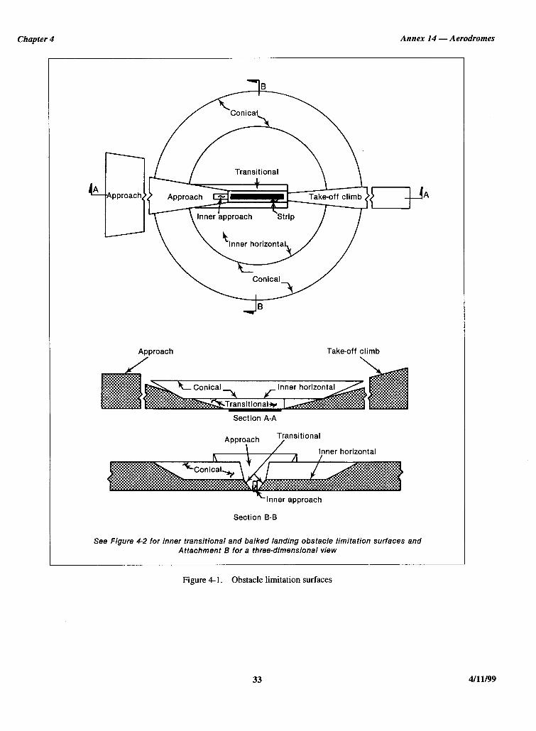
Chapter 4 Annex 14 - Aerodromes
Transitional
Take-off climb
Inner horizonta
Approach Take-off climb
Section A-A
Transitional
Inner horizontal
-Inner approach
Section B-B
See Figure 4-2 for inner transitional and balked landing obstacle limitation surfaces and Attachment B for a three-dimensional view
Figure 4- 1. Obstacle limitation surfaces
33 4/l 1199

Annex 14 — Aerodromes Volume I
Figure 4-2. Inner approach, inner transitional and balked landing obstacle limitation surfaces
B
B
A ABalkedlanding
Inner transitional
Inner transitional
Inner transitional Inner horizontal
Inner approach
Balkedlanding
Balkedlanding
Section A-A
Section B-B
Inner approach surface
4.1.11 Description.— Inner approach surface. A rectangu-lar portion of the approach surface immediately preceding thethreshold.
4.1.12 Characteristics.— The limits of the inner approachsurface shall comprise:
a) an inner edge coincident with the location of the inneredge of the approach surface but of its own specifiedlength;
b) two sides originating at the ends of the inner edge andextending parallel to the vertical plane containing thecentre line of the runway; and
c) an outer edge parallel to the inner edge.
Transitional surface
4.1.13 Description.— Transitional surface. A complexsurface along the side of the strip and part of the side of theapproach surface, that slopes upwards and outwards to the innerhorizontal surface.
4.1.14 Characteristics.— The limits of a transitionalsurface shall comprise:
a) a lower edge beginning at the intersection of the side ofthe approach surface with the inner horizontal surface and
4/11/99 341/11/01
No. 4

Chapter 4 Annex 14 — Aerodromes
extending down the side of the approach surface to theinner edge of the approach surface and from there alongthe length of the strip parallel to the runway centre line;and
b) an upper edge located in the plane of the inner horizontalsurface.
4.1.15 The elevation of a point on the lower edge shall be:
a) along the side of the approach surface — equal to theelevation of the approach surface at that point; and
b) along the strip — equal to the elevation of the nearestpoint on the centre line of the runway or its extension.
Note.— As a result of b) the transitional surface along thestrip will be curved if the runway profile is curved, or a plane ifthe runway profile is a straight line. The intersection of thetransitional surface with the inner horizontal surface will alsobe a curved or a straight line depending on the runway profile.
4.1.16 The slope of the transitional surface shall bemeasured in a vertical plane at right angles to the centre line ofthe runway.
Inner transitional surface
Note.— It is intended that the inner transitional surface bethe controlling obstacle limitation surface for navigation aids,aircraft and other vehicles that must be near the runway andwhich is not to be penetrated except for frangible objects. Thetransitional surface described in 4.1.13 is intended to remain asthe controlling obstacle limitation surface for buildings, etc.
4.1.17 Description.— Inner transitional surface. A surfacesimilar to the transitional surface but closer to the runway.
4.1.18 Characteristics.— The limits of an inner tran-sitional surface shall comprise:
a) a lower edge beginning at the end of the inner approachsurface and extending down the side of the innerapproach surface to the inner edge of that surface, fromthere along the strip parallel to the runway centre line tothe inner edge of the balked landing surface and fromthere up the side of the balked landing surface to the pointwhere the side intersects the inner horizontal surface; and
b) an upper edge located in the plane of the inner horizontalsurface.
4.1.19 The elevation of a point on the lower edge shall be:
a) along the side of the inner approach surface and balkedlanding surface — equal to the elevation of the particularsurface at that point; and
b) along the strip — equal to the elevation of the nearestpoint on the centre line of the runway or its extension.
Note.— As a result of b) the inner transitional surface alongthe strip will be curved if the runway profile is curved or a planeif the runway profile is a straight line. The intersection of theinner transitional surface with the inner horizontal surface willalso be a curved or straight line depending on the runway profile.
4.1.20 The slope of the inner transitional surface shall bemeasured in a vertical plane at right angles to the centre line ofthe runway.
Balked landing surface
4.1.21 Description.— Balked landing surface. An inclinedplane located at a specified distance after the threshold,extending between the inner transitional surface.
4.1.22 Characteristics.— The limits of the balked landingsurface shall comprise:
a) an inner edge horizontal and perpendicular to the centreline of the runway and located at a specified distance afterthe threshold;
b) two sides originating at the ends of the inner edge anddiverging uniformly at a specified rate from the verticalplane containing the centre line of the runway; and
c) an outer edge parallel to the inner edge and located in theplane of the inner horizontal surface.
4.1.23 The elevation of the inner edge shall be equal to theelevation of the runway centre line at the location of the inneredge.
4.1.24 The slope of the balked landing surface shall bemeasured in the vertical plane containing the centre line of therunway.
Take-off climb surface
4.1.25 Description.— Take-off climb surface. An inclinedplane or other specified surface beyond the end of a runway orclearway.
4.1.26 Characteristics.— The limits of the take-off climbsurface shall comprise:
a) an inner edge horizontal and perpendicular to the centreline of the runway and located either at a specifieddistance beyond the end of the runway or at the end of theclearway when such is provided and its length exceedsthe specified distance;
b) two sides originating at the ends of the inner edge,diverging uniformly at a specified rate from the take-off
35 4/11/99

Annex 14 — Aerodromes Volume I
track to a specified final width and continuing thereafterat that width for the remainder of the length of the take-off climb surface; and
c) an outer edge horizontal and perpendicular to thespecified take-off track.
4.1.27 The elevation of the inner edge shall be equal to thehighest point on the extended runway centre line between theend of the runway and the inner edge, except that when aclearway is provided the elevation shall be equal to the highestpoint on the ground on the centre line of the clearway.
4.1.28 In the case of a straight take-off flight path, theslope of the take-off climb surface shall be measured in thevertical plane containing the centre line of the runway.
4.1.29 In the case of a take-off flight path involving a turn,the take-off climb surface shall be a complex surface containingthe horizontal normals to its centre line, and the slope of thecentre line shall be the same as that for a straight take-off flightpath.
4.2 Obstacle limitation requirements
Note.— The requirements for obstacle limitation surfaces arespecified on the basis of the intended use of a runway, i.e. take-offor landing and type of approach, and are intended to be appliedwhen such use is made of the runway. In cases where operationsare conducted to or from both directions of a runway, then thefunction of certain surfaces may be nullified because of morestringent requirements of another lower surface.
Non-instrument runways
4.2.1 The following obstacle limitation surfaces shall beestablished for a non-instrument runway:
— conical surface;— inner horizontal surface;— approach surface; and— transitional surfaces.
4.2.2 The heights and slopes of the surfaces shall not begreater than, and their other dimensions not less than, thosespecified in Table 4-1.
4.2.3 New objects or extensions of existing objects shallnot be permitted above an approach or transitional surfaceexcept when, in the opinion of the appropriate authority, thenew object or extension would be shielded by an existingimmovable object.
Note.— Circumstances in which the shielding principle mayreasonably be applied are described in the Airport ServicesManual, Part 6.
4.2.4 Recommendation.— New objects or extensions ofexisting objects should not be permitted above the conicalsurface or inner horizontal surface except when, in the opinionof the appropriate authority, the object would be shielded by anexisting immovable object, or after aeronautical study it isdetermined that the object would not adversely affect the safetyor significantly affect the regularity of operations of aero-planes.
4.2.5 Recommendation.— Existing objects above any ofthe surfaces required by 4.2.1 should as far as practicable beremoved except when, in the opinion of the appropriateauthority, the object is shielded by an existing immovableobject, or after aeronautical study it is determined that theobject would not adversely affect the safety or significantlyaffect the regularity of operations of aeroplanes.
Note.— Because of transverse or longitudinal slopes on astrip, in certain cases the inner edge or portions of the inneredge of the approach surface may be below the correspondingelevation of the strip. It is not intended that the strip be gradedto conform with the inner edge of the approach surface, nor isit intended that terrain or objects which are above the approachsurface beyond the end of the strip, but below the level of thestrip, be removed unless it is considered they may endangeraeroplanes.
4.2.6 Recommendation.— In considering proposedconstruction, account should be taken of the possible futuredevelopment of an instrument runway and consequentrequirement for more stringent obstacle limitation surfaces.
Non-precision approach runways
4.2.7 The following obstacle limitation surfaces shall beestablished for a non-precision approach runway:
— conical surface;— inner horizontal surface;— approach surface; and— transitional surfaces.
4.2.8 The heights and slopes of the surfaces shall not begreater than, and their other dimensions not less than, thosespecified in Table 4-1, except in the case of the horizontalsection of the approach surface (see 4.2.9).
4.2.9 The approach surface shall be horizontal beyond thepoint at which the 2.5 per cent slope intersects:
a) a horizontal plane 150 m above the threshold elevation; or
b) the horizontal plane passing through the top of any objectthat governs the obstacle clearance altitude/height(OCA/H);
whichever is the higher.
4/11/99 36
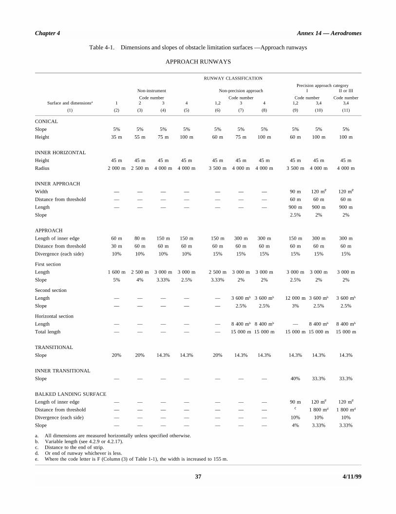
Chapter 4 Annex 14 — Aerodromes
37 4/11/99
Table 4-1. Dimensions and slopes of obstacle limitation surfaces —Approach runways
APPROACH RUNWAYS
RUNWAY CLASSIFICATION
Precision approach categoryNon-instrument
Code number
Non-precision approach
Code number
I
Code number
II or III
Code numberSurface and dimensionsa 1 2 3 4 1,2 3 4 1,2 3,4 3,4
(1) (2) (3) (4) (5) (6) (7) (8) (9) (10) (11)
CONICAL
Slope 5% 5% 5% 5% 5% 5% 5% 5% 5% 5%
Height 35 m 55 m 75 m 100 m 60 m 75 m 100 m 60 m 100 m 100 m
INNER HORIZONTAL
Height 45 m 45 m 45 m 45 m 45 m 45 m 45 m 45 m 45 m 45 m
Radius 2 000 m 2 500 m 4 000 m 4 000 m 3 500 m 4 000 m 4 000 m 3 500 m 4 000 m 4 000 m
INNER APPROACH
Width — — — — — — — 90 m 120 me 120 me
Distance from threshold — — — — — — — 60 m 60 m 60 m
Length — — — — — — — 900 m 900 m 900 m
Slope 2.5% 2% 2%
APPROACH
Length of inner edge 60 m 80 m 150 m 150 m 150 m 300 m 300 m 150 m 300 m 300 m
Distance from threshold 30 m 60 m 60 m 60 m 60 m 60 m 60 m 60 m 60 m 60 m
Divergence (each side) 10% 10% 10% 10% 15% 15% 15% 15% 15% 15%
First section
Length 1 600 m 2 500 m 3 000 m 3 000 m 2 500 m 3 000 m 3 000 m 3 000 m 3 000 m 3 000 m
Slope 5% 4% 3.33% 2.5% 3.33% 2% 2% 2.5% 2% 2%
Second section
Length — — — — — 3 600 mb 3 600 mb 12 000 m 3 600 mb 3 600 mb
Slope — — — — — 2.5% 2.5% 3% 2.5% 2.5%
Horizontal section
Length — — — — — 8 400 mb 8 400 mb — 8 400 mb 8 400 mb
Total length — — — — — 15 000 m 15 000 m 15 000 m 15 000 m 15 000 m
TRANSITIONAL
Slope 20% 20% 14.3% 14.3% 20% 14.3% 14.3% 14.3% 14.3% 14.3%
INNER TRANSITIONAL
Slope — — — — — — — 40% 33.3% 33.3%
BALKED LANDING SURFACE
Length of inner edge — — — — — — — 90 m 120 me 120 me
Distance from threshold — — — — — — — c 1 800 md 1 800 md
Divergence (each side) — — — — — — — 10% 10% 10%
Slope — — — — — — — 4% 3.33% 3.33%
a. All dimensions are measured horizontally unless specified otherwise.b. Variable length (see 4.2.9 or 4.2.17).c. Distance to the end of strip.d. Or end of runway whichever is less.e. Where the code letter is F (Column (3) of Table 1-1), the width is increased to 155 m.

Annex 14 — Aerodromes Volume I
4.2.10 New objects or extensions of existing objects shallnot be permitted above an approach surface within 3 000 m ofthe inner edge or above a transitional surface except when, inthe opinion of the appropriate authority, the new object orextension would be shielded by an existing immovable object.
Note.— Circumstances in which the shielding principle mayreasonably be applied are described in the Airport ServicesManual, Part 6.
4.2.11 Recommendation.— New objects or extensions ofexisting objects should not be permitted above the approachsurface beyond 3 000 m from the inner edge, the conical surfaceor inner horizontal surface except when, in the opinion of theappropriate authority, the object would be shielded by an existingimmovable object, or after aeronautical study it is determinedthat the object would not adversely affect the safety orsignificantly affect the regularity of operations of aeroplanes.
4.2.12 Recommendation.— Existing objects above any ofthe surfaces required by 4.2.7 should as far as practicable beremoved except when, in the opinion of the appropriateauthority, the object is shielded by an existing immovableobject, or after aeronautical study it is determined that theobject would not adversely affect the safety or significantlyaffect the regularity of operations of aeroplanes.
Note.— Because of transverse or longitudinal slopes on astrip, in certain cases the inner edge or portions of the inneredge of the approach surface may be below the correspondingelevation of the strip. It is not intended that the strip be gradedto conform with the inner edge of the approach surface, nor isit intended that terrain or objects which are above the approachsurface beyond the end of the strip, but below the level of thestrip, be removed unless it is considered they may endangeraeroplanes.
Precision approach runways
Note 1.— See 8.7 for information regarding siting andconstruction of equipment and installations on operationalareas.
Note 2.— Guidance on obstacle limitation surfaces forprecision approach runways is given in the Airport ServicesManual, Part 6.
4.2.13 The following obstacle limitation surfaces shall beestablished for a precision approach runway category I:
— conical surface;— inner horizontal surface;— approach surface; and— transitional surfaces.
4.2.14 Recommendation.— The following obstacle limi-tation surfaces should be established for a precision approachrunway category I:
— inner approach surface;— inner transitional surfaces; and— balked landing surface.
4.2.15 The following obstacle limitation surfaces shall beestablished for a precision approach runway category II or III:
— conical surface;— inner horizontal surface;— approach surface and inner approach surface;— transitional surfaces;— inner transitional surfaces; and— balked landing surface.
4.2.16 The heights and slopes of the surfaces shall not begreater than, and their other dimensions not less than, thosespecified in Table 4-1, except in the case of the horizontalsection of the approach surface (see 4.2.17).
4.2.17 The approach surface shall be horizontal beyond thepoint at which the 2.5 per cent slope intersects:
a) a horizontal plane 150 m above the threshold elevation; or
b) the horizontal plane passing through the top of any objectthat governs the obstacle clearance limit;
whichever is the higher.
4.2.18 Fixed objects shall not be permitted above the innerapproach surface, the inner transitional surface or the balkedlanding surface, except for frangible objects which because oftheir function must be located on the strip. Mobile objects shallnot be permitted above these surfaces during the use of therunway for landing.
4.2.19 New objects or extensions of existing objects shallnot be permitted above an approach surface or a transitionalsurface except when, in the opinion of the appropriate authority,the new object or extension would be shielded by an existingimmovable object.
Note.— Circumstances in which the shielding principle mayreasonably be applied are described in the Airport ServicesManual, Part 6.
4.2.20 Recommendation.— New objects or extensions ofexisting objects should not be permitted above the conicalsurface and the inner horizontal surface except when, in theopinion of the appropriate authority, an object would beshielded by an existing immovable object, or after aeronauticalstudy it is determined that the object would not adversely affectthe safety or significantly affect the regularity of operations ofaeroplanes.
4.2.21 Recommendation.— Existing objects above anapproach surface, a transitional surface, the conical surfaceand inner horizontal surface should as far as practicable beremoved except when, in the opinion of the appropriate
4/11/99 38
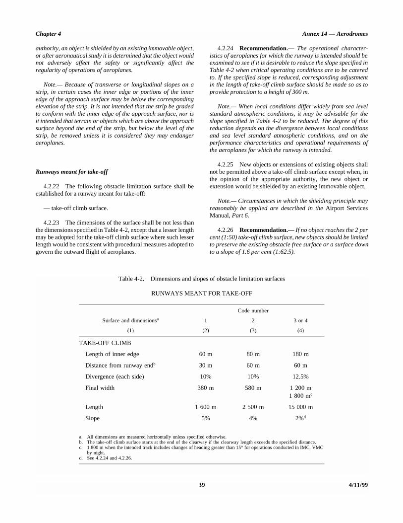
Chapter 4 Annex 14 — Aerodromes
authority, an object is shielded by an existing immovable object,or after aeronautical study it is determined that the object wouldnot adversely affect the safety or significantly affect theregularity of operations of aeroplanes.
Note.— Because of transverse or longitudinal slopes on astrip, in certain cases the inner edge or portions of the inneredge of the approach surface may be below the correspondingelevation of the strip. It is not intended that the strip be gradedto conform with the inner edge of the approach surface, nor isit intended that terrain or objects which are above the approachsurface beyond the end of the strip, but below the level of thestrip, be removed unless it is considered they may endangeraeroplanes.
Runways meant for take-off
4.2.22 The following obstacle limitation surface shall beestablished for a runway meant for take-off:
— take-off climb surface.
4.2.23 The dimensions of the surface shall be not less thanthe dimensions specified in Table 4-2, except that a lesser lengthmay be adopted for the take-off climb surface where such lesserlength would be consistent with procedural measures adopted togovern the outward flight of aeroplanes.
4.2.24 Recommendation.— The operational character-istics of aeroplanes for which the runway is intended should beexamined to see if it is desirable to reduce the slope specified inTable 4-2 when critical operating conditions are to be cateredto. If the specified slope is reduced, corresponding adjustmentin the length of take-off climb surface should be made so as toprovide protection to a height of 300 m.
Note.— When local conditions differ widely from sea levelstandard atmospheric conditions, it may be advisable for theslope specified in Table 4-2 to be reduced. The degree of thisreduction depends on the divergence between local conditionsand sea level standard atmospheric conditions, and on theperformance characteristics and operational requirements ofthe aeroplanes for which the runway is intended.
4.2.25 New objects or extensions of existing objects shallnot be permitted above a take-off climb surface except when, inthe opinion of the appropriate authority, the new object orextension would be shielded by an existing immovable object.
Note.— Circumstances in which the shielding principle mayreasonably be applied are described in the Airport ServicesManual, Part 6.
4.2.26 Recommendation.— If no object reaches the 2 percent (1:50) take-off climb surface, new objects should be limitedto preserve the existing obstacle free surface or a surface downto a slope of 1.6 per cent (1:62.5).
39 4/11/99
Table 4-2. Dimensions and slopes of obstacle limitation surfaces
RUNWAYS MEANT FOR TAKE-OFF
Code number
Surface and dimensionsa 1 2 3 or 4
(1) (2) (3) (4)
TAKE-OFF CLIMB
Length of inner edge 60 m 80 m 180 m
Distance from runway endb 30 m 60 m 60 m
Divergence (each side) 10% 10% 12.5%
Final width 380 m 580 m 1 200 m1 800 mc
Length 1 600 m 2 500 m 15 000 m
Slope 5% 4% 2%d
a. All dimensions are measured horizontally unless specified otherwise.b. The take-off climb surface starts at the end of the clearway if the clearway length exceeds the specified distance.c. 1 800 m when the intended track includes changes of heading greater than 15° for operations conducted in IMC, VMC
by night.d. See 4.2.24 and 4.2.26.

Annex 14 — Aerodromes Volume I
4.2.27 Recommendation.— Existing objects that extendabove a take-off climb surface should as far as practicable beremoved except when, in the opinion of the appropriateauthority, an object is shielded by an existing immovable object,or after aeronautical study it is determined that the object wouldnot adversely affect the safety or significantly affect theregularity of operations of aeroplanes.
Note.— Because of transverse slopes on a strip or clearway,in certain cases portions of the inner edge of the take-off climbsurface may be below the corresponding elevation of the stripor clearway. It is not intended that the strip or clearway begraded to conform with the inner edge of the take-off climbsurface, nor is it intended that terrain or objects which areabove the take-off climb surface beyond the end of the strip orclearway, but below the level of the strip or clearway, beremoved unless it is considered they may endanger aeroplanes.Similar considerations apply at the junction of a clearway andstrip where differences in transverse slopes exist.
4.3 Objects outside the obstacle limitation surfaces
4.3.1 Recommendation.— Arrangements should be madeto enable the appropriate authority to be consulted concerningproposed construction beyond the limits of the obstaclelimitation surfaces that extend above a height established bythat authority, in order to permit an aeronautical study of theeffect of such construction on the operation of aeroplanes.
4.3.2 Recommendation.— In areas beyond the limits of theobstacle limitation surfaces, at least those objects which extend toa height of 150 m or more above ground elevation should beregarded as obstacles, unless a special aeronautical studyindicates that they do not constitute a hazard to aeroplanes.
Note.— This study may have regard to the nature ofoperations concerned and may distinguish between day andnight operations.
4.4 Other objects
4.4.1 Recommendation.— Objects which do not projectthrough the approach surface but which would neverthelessadversely affect the optimum siting or performance of visual ornon-visual aids should, as far as practicable, be removed.
4.4.2 Recommendation.— Anything which may, in theopinion of the appropriate authority after aeronautical study,endanger aeroplanes on the movement area or in the air withinthe limits of the inner horizontal and conical surfaces should beregarded as an obstacle and should be removed in so far aspracticable.
Note.— In certain circumstances, objects that do not projectabove any of the surfaces enumerated in 4.1 may constitute ahazard to aeroplanes as, for example, where there are one ormore isolated objects in the vicinity of an aerodrome.
4/11/99 40

CHAPTER 5. VISUAL AIDS FOR NAVIGATION
5.1 Indicators and signalling devices
5.1.1 Wind direction indicators
Application
5.1.1.1 An aerodrome shall be equipped with at least onewind direction indicator.
Location
5.1.1.2 A wind direction indicator shall be located so asto be visible from aircraft in flight or on the movement areaand in such a way as to be free from the effects of airdisturbances caused by nearby objects.
Characteristics
5.1.1.3 Recommendation.— The wind direction indi-cator should be in the form of a truncated cone made of fabricand should have a length of not less than 3.6 m and adiameter, at the larger end, of not less than 0.9 m. It shouldbe constructed so that it gives a clear indication of thedirection of the surface wind and a general indication of thewind speed. The colour or colours should be so selected as tomake the wind direction indicator clearly visible andunderstandable from a height of at least 300 m, having regardto background. Where practicable, a single colour, preferablywhite or orange, should be used. Where a combination of twocolours is required to give adequate conspicuity againstchanging backgrounds, they should preferably be orange andwhite, red and white, or black and white, and should bearranged in five alternate bands, the first and last bands beingthe darker colour.
5.1.1.4 Recommendation.— The location of at least onewind direction indicator should be marked by a circular band15 m in diameter and 1.2 m wide. The band should be centredabout the wind direction indicator support and should be in acolour chosen to give adequate conspicuity, preferably white.
5.1.1.5 Recommendation.— Provision should be madefor illuminating at least one wind indicator at an aerodromeintended for use at night.
5.1.2 Landing direction indicator
Location
5.1.2.1 Where provided, a landing direction indicatorshall be located in a conspicuous place on the aerodrome.
Characteristics
5.1.2.2 Recommendation.— The landing direction indi-cator should be in the form of a “T”.
5.1.2.3 The shape and minimum dimensions of a landing“T” shall be as shown in Figure 5-1. The colour of the landing“T” shall be either white or orange, the choice beingdependent on the colour that contrasts best with the back-ground against which the indicator will be viewed. Whererequired for use at night the landing “T” shall either be il-luminated or outlined by white lights.
5.1.3 Signalling lamp
Application
5.1.3.1 A signalling lamp shall be provided at a con-trolled aerodrome in the aerodrome control tower.
Characteristics
5.1.3.2 Recommendation.— A signalling lamp should becapable of producing red, green and white signals, and of:
Figure 5-1. Landing direction indicator
0.4 m
0.4 m 4 m
4 m
ANNEX 14 — VOLUME I 41 4/11/99

Annex 14 — Aerodromes Volume I
a) being aimed manually at any target as required;
b) giving a signal in any one colour followed by a signal ineither of the two other colours; and
c) transmitting a message in any one of the three colours byMorse Code up to a speed of at least four words perminute.
When selecting the green light, use should be made of therestricted boundary of green as specified in Appendix 1, 2.1.2.
5.1.3.3 Recommendation.— The beam spread should benot less than 1° nor greater than 3°, with negligible lightbeyond 3°. When the signalling lamp is intended for use in thedaytime the intensity of the coloured light should be not lessthan 6 000 cd.
5.1.4 Signal panels and signal area
Note.— The inclusion of detailed specifications for a signalarea in this section is not intended to imply that one has to beprovided. Attachment A, Section 15 provides guidance on theneed to provide ground signals. Annex 2, Appendix 1 specifiesthe shape, colour and use of visual ground signals. TheAerodrome Design Manual, Part 4 provides guidance on theirdesign.
Location of signal area
5.1.4.1 Recommendation.— The signal area should belocated so as to be visible for all angles of azimuth above anangle of 10° above the horizontal when viewed from a heightof 300 m.
Characteristics of signal area
5.1.4.2 The signal area shall be an even horizontal surfaceat least 9 m square.
5.1.4.3 Recommendation.— The colour of the signalarea should be chosen to contrast with the colours of thesignal panels used, and it should be surrounded by a whiteborder not less than 0.3 m wide.
5.2 Markings
5.2.1 General
Interruption of runway markings
5.2.1.1 At an intersection of two (or more) runways themarkings of the more important runway, except for the runway
side stripe marking, shall be displayed and the markings of theother runway(s) shall be interrupted. The runway side stripemarking of the more important runway may be eithercontinued across the intersection or interrupted.
5.2.1.2 Recommendation.— The order of importance ofrunways for the display of runway markings should be asfollows:
1st — precision approach runway;
2nd — non-precision approach runway; and
3rd — non-instrument runway.
5.2.1.3 At an intersection of a runway and taxiway themarkings of the runway shall be displayed and the markings ofthe taxiway interrupted, except that runway side stripemarkings may be interrupted.
Note.— See 5.2.8.5 regarding the manner of connectingrunway and taxiway centre line markings.
Colour and conspicuity
5.2.1.4 Runway markings shall be white.
Note 1.— It has been found that, on runway surfaces oflight colour, the conspicuity of white markings can beimproved by outlining them in black.
Note 2.— It is preferable that the risk of uneven frictioncharacteristics on markings be reduced in so far as practi-cable by the use of a suitable kind of paint.
Note 3.— Markings may consist of solid areas or a seriesof longitudinal stripes providing an effect equivalent to thesolid areas.
5.2.1.5 Taxiway markings and aircraft stand markingsshall be yellow.
5.2.1.6 Apron safety lines shall be of a conspicuouscolour which shall contrast with that used for aircraft standmarkings.
5.2.1.7 Recommendation.— At aerodromes whereoperations take place at night, pavement markings should bemade with reflective materials designed to enhance thevisibility of the markings.
Note.— Guidance on reflective materials is given in theAerodrome Design Manual, Part 4.
4/11/99 42
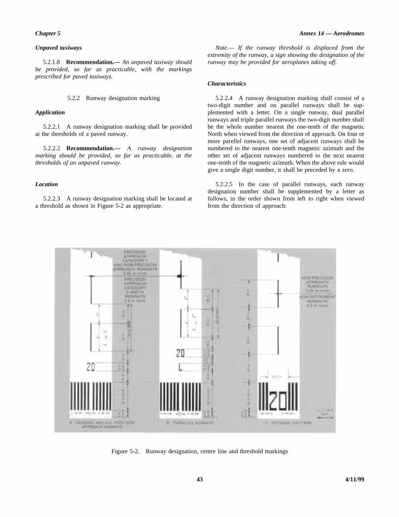
Chapter 5 Annex 14 — Aerodromes
Unpaved taxiways
5.2.1.8 Recommendation.— An unpaved taxiway shouldbe provided, so far as practicable, with the markingsprescribed for paved taxiways.
5.2.2 Runway designation marking
Application
5.2.2.1 A runway designation marking shall be providedat the thresholds of a paved runway.
5.2.2.2 Recommendation.— A runway designationmarking should be provided, so far as practicable, at thethresholds of an unpaved runway.
Location
5.2.2.3 A runway designation marking shall be located ata threshold as shown in Figure 5-2 as appropriate.
Note.— If the runway threshold is displaced from theextremity of the runway, a sign showing the designation of therunway may be provided for aeroplanes taking off.
Characteristics
5.2.2.4 A runway designation marking shall consist of atwo-digit number and on parallel runways shall be sup-plemented with a letter. On a single runway, dual parallelrunways and triple parallel runways the two-digit number shallbe the whole number nearest the one-tenth of the magneticNorth when viewed from the direction of approach. On four ormore parellel runways, one set of adjacent runways shall benumbered to the nearest one-tenth magnetic azimuth and theother set of adjacent runways numbered to the next nearestone-tenth of the magnetic azimuth. When the above rule wouldgive a single digit number, it shall be preceded by a zero.
5.2.2.5 In the case of parallel runways, each runwaydesignation number shall be supplemented by a letter asfollows, in the order shown from left to right when viewedfrom the direction of approach:
43 4/11/99
Figure 5-2. Runway designation, centre line and threshold markings
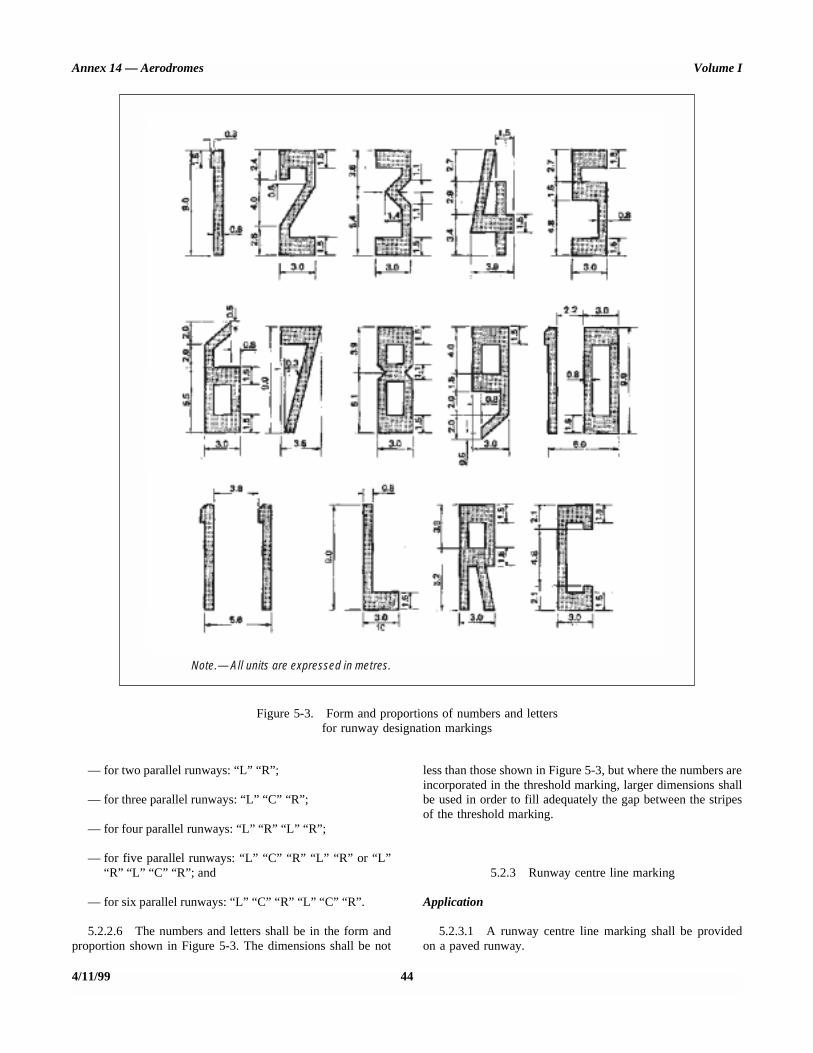
Annex 14 — Aerodromes Volume I
Figure 5-3. Form and proportions of numbers and lettersfor runway designation markings
Note.— All units are expressed in metres.
— for two parallel runways: “L” “R”;
— for three parallel runways: “L” “C” “R”;
— for four parallel runways: “L” “R” “L” “R”;
— for five parallel runways: “L” “C” “R” “L” “R” or “L”“R” “L” “C” “R”; and
— for six parallel runways: “L” “C” “R” “L” “C” “R”.
5.2.2.6 The numbers and letters shall be in the form andproportion shown in Figure 5-3. The dimensions shall be not
less than those shown in Figure 5-3, but where the numbers areincorporated in the threshold marking, larger dimensions shallbe used in order to fill adequately the gap between the stripesof the threshold marking.
5.2.3 Runway centre line marking
Application
5.2.3.1 A runway centre line marking shall be providedon a paved runway.
4/11/99 44

Chapter 5 Annex 14 — Aerodromes
Location
5.2.3.2 A runway centre line marking shall be locatedalong the centre line of the runway between the runwaydesignation markings as shown in Figure 5-2, except wheninterrupted in compliance with 5.2.1.1.
Characteristics
5.2.3.3 A runway centre line marking shall consist of aline of uniformly spaced stripes and gaps. The length of astripe plus a gap shall be not less than 50 m or more than 7 5m.The length of each stripe shall be at least equal to the lengthof the gap or 30 m, whichever is greater.
5.2.3.4 The width of the stripes shall be not less than:
— 0.90 m on precision approach category II and IIIrunways;
— 0.45 m on non-precision approach runways where thecode number is 3 or 4, and precision approach category Irunways; and
— 0.30 m on non-precision approach runways where thecode number is 1 or 2, and on non-instrument runways.
5.2.4 Threshold marking
Application
5.2.4.1 A threshold marking shall be provided at thethreshold of a paved instrument runway, and of a paved non-instrument runway where the code number is 3 or 4 and therunway is intended for use by international commercial airtransport.
5.2.4.2 Recommendation.— A threshold marking shouldbe provided at the threshold of a paved non-instrumentrunway where the code number is 3 or 4 and the runway isintended for use by other than international commercial airtransport.
5.2.4.3 Recommendation.— A threshold marking shouldbe provided, so far as practicable, at the thresholds of anunpaved runway.
Note.— The Aerodrome Design Manual, Part 4, shows aform of marking which has been found satisfactory for themarking of downward slopes immediately before the threshold.
Location
5.2.4.4 The stripes of the threshold marking shall com-mence 6 m from the threshold.
Characteristics
5.2.4.5 A runway threshold marking shall consist of apattern of longitudinal stripes of uniform dimensions disposedsymmetrically about the centre line of a runway as shown inFigure 5-2 (A) and (B) for a runway width of 45 m. Thenumber of stripes shall be in accordance with the runwaywidth as follows:
Number ofRunway width stripes
18 m 423 m 630 m 845 m 1260 m 16
except that on non-precision approach and non-instrumentrunways 45 m or greater in width, they may be as shown inFigure 5-2 (C).
5.2.4.6 The stripes shall extend laterally to within 3 m ofthe edge of a runway or to a distance of 27 m on either sideof a runway centre line, whichever results in the smaller lateraldistance. Where a runway designation marking is placedwithin a threshold marking there shall be a minimum of threestripes on each side of the centre line of the runway. Where arunway designation marking is placed above a thresholdmarking, the stripes shall be continued across the runway. Thestripes shall be at least 30 m long and approximately 1.80 mwide with spacings of approximately 1.80 m between themexcept that, where the stripes are continued across a runway,a double spacing shall be used to separate the two stripesnearest the centre line of the runway, and in the case where thedesignation marking is included within the threshold markingthis spacing shall be 22.5 m.
Transverse stripe
5.2.4.7 Recommendation.— Where a threshold is dis-placed from the extremity of a runway or where the extremityof a runway is not square with the runway centre line, atransverse stripe as shown in Figure 5-4 (B) should be addedto the threshold marking.
5.2.4.8 A transverse stripe shall be not less than 1.80 mwide.
Arrows
5.2.4.9 Where a runway threshold is permanently dis-placed, arrows conforming to Figure 5-4 (B) shall be providedon the portion of the runway before the displaced threshold.
45 4/11/99

Annex 14 — Aerodromes Volume I
Figure 5-4. Displaced threshold markings
5.2.4.10 When a runway threshold is temporarily dis-placed from the normal position, it shall be marked as shownin Figure 5-4 (A) or 5-4 (B) and all markings prior to thedisplaced threshold shall be obscured except the runway centreline marking, which shall be converted to arrows.
Note 1.— In the case where a threshold is temporarilydisplaced for only a short period of time, it has been foundsatisfactory to use markers in the form and colour of adisplaced threshold marking rather than attempting to paintthis marking on the runway.
Note 2.— When the runway before a displaced threshold isunfit for the surface movement of aircraft, closed markings, asdescribed in 7.1.4, are required to be provided.
5.2.5 Aiming point marking
Application
5.2.5.1 The provisions of Sections 5.2.5 and 5.2.6 shallnot require the replacement of existing markings before1 January 2005.
5.2.5.2 An aiming point marking shall be provided ateach approach end of a paved instrument runway where thecode number is 2, 3 or 4.
5.2.5.3 Recommendation.— An aiming point markingshould be provided at each approach end of:
a) a paved non-instrument runway where the code numberis 3 or 4,
b) a paved instrument runway where the code number is 1,
when additional conspicuity of the aiming point is desirable.
Location
5.2.5.4 The aiming point marking shall commence nocloser to the threshold than the distance indicated in theappropriate column of Table 5-1, except that, on a runwayequipped with a visual approach slope indicator system, thebeginning of the marking shall be coincident with the visualapproach slope origin.
4/11/99 46

Chapter 5 Annex 14 — Aerodromes
Table 5-1. Location and dimensions of aiming point marking
Location anddimensions
Landing distance available
Less than 800 m800 m up to but notincluding 1 200 m
1 200 m up to but notincluding 2 400 m 2 400 m and above
(1) (2) (3) (4) (5)
Distance from threshold to beginning of marking
150 m 250 m 300 m 400 m
Length of stripea 30-45 m 30-45 m 45-60 m 45-60 m
Width of stripe 4 m 6 m 6-10 mb 6-10 mb
Lateral spacing between inner sides of stripes
6 mc 9 mc 18-22.5 m 18-22.5 m
a. The greater dimensions of the specified ranges are intended to be used where increased conspicuity is required.b. The lateral spacing may be varied within these limits to minimize the contamination of the marking by rubber deposits.c. These figures were deduced by reference to the outer main gear wheel span which is element 2 of the aerodrome reference code at Chapter 1, Table 1-1.
5.2.5.5 An aiming point marking shall consist of two con-spicuous stripes. The dimensions of the stripes and the lateralspacing between their inner sides shall be in accordance withthe provisions of the appropriate column of Table 5-1. Wherea touchdown zone marking is provided, the lateral spacingbetween the markings shall be the same as that of the touch-down zone marking.
5.2.6 Touchdown zone marking
Application
5.2.6.1 A touchdown zone marking shall be provided inthe touchdown zone of a paved precision approach runwaywhere the code number is 2, 3 or 4.
5.2.6.2 Recommendation.— A touchdown zone markingshould be provided in the touchdown zone of a paved non-precision approach or non-instrument runway where the codenumber is 3 or 4 and additional conspicuity of the touchdownzone is desirable.
Location and characteristics
5.2.6.3 A touchdown zone marking shall consist of pairsof rectangular markings symmetrically disposed about therunway centre line with the number of such pairs related to thelanding distance available and, where the marking is to bedisplayed at both the approach directions of a runway, thedistance between the thresholds, as follows:
Landing distance availableor the distance between Pair(s) ofthresholds markings
less than 900 m 1
900 m up to but not 2including 1 200 m
1 200 m up to but not 3including 1 500 m
1 500 m up to but not 4including 2 400 m
2 400 m or more 6
5.2.6.4 A touchdown zone marking shall conform toeither of the two patterns shown in Figure 5-5. For the patternshown in Figure 5-5 (A), the markings shall be not less than22.5 m long and 3 m wide. For the pattern shown in Fig-ure 5-5 (B), each stripe of each marking shall be not less than22.5 m long and 1.8 m wide with a spacing of 1.5 m betweenadjacent stripes. The lateral spacing between the inner sides ofthe rectangles shall be equal to that of the aiming pointmarking where provided. Where an aiming point marking isnot provided, the lateral spacing between the inner sides of therectangles shall correspond to the lateral spacing specified forthe aiming point marking in Table 5-1 (columns 2, 3, 4 or 5,as appropriate). The pairs of markings shall be provided atlongitudinal spacings of 150 m beginning from the threshold
47 4/11/99

Annex 14 — Aerodromes Volume I
4/11/99 48
Figure 5-5. Aiming point and touchdown zone markings(illustrated for a runway with a length of 2 400 m or more)
Chapter 5 Annex 14 — Aerodromes
except that pairs of touchdown zone markings coincident withor located within 50 m of an aiming point marking shall bedeleted from the pattern.
5.2.6.5 Recommendation.— On a non-precision ap-proach runway where the code number is 2, an additional pairof touchdown zone marking stripes should be provided 150 mbeyond the beginning of the aiming point marking.
5.2.7 Runway side stripe marking
Application
5.2.7.1 A runway side stripe marking shall be providedbetween the thresholds of a paved runway where there is alack of contrast between the runway edges and the shouldersor the surrounding terrain.
5.2.7.2 Recommendation.— A runway side stripemarking should be provided on a precision approach runwayirrespective of the contrast between the runway edges and theshoulders or the surrounding terrain.
Location
5.2.7.3 Recommendation.— A runway side stripemarking should consist of two stripes, one placed along eachedge of the runway with the outer edge of each stripeapproximately on the edge of the runway, except that, wherethe runway is greater than 60 m in width, the stripes should belocated 30 m from the runway centre line.
Characteristics
5.2.7.4 Recommendation.— A runway side stripe shouldhave an overall width of at least 0.9 m on runways 30 m ormore in width and at least 0.45 m on narrower runways.
5.2.8 Taxiway centre line marking
Application
5.2.8.1 Taxiway centre line marking shall be provided ona paved taxiway, de-icing/anti-icing facility and apron wherethe code number is 3 or 4 in such a way as to providecontinuous guidance between the runway centre line andaircraft stands.
5.2.8.2 Recommendation.— Taxiway centre line markingshould be provided on a paved taxiway, de-icing/anti-icingfacility and apron where the code number is 1 or 2 in such away as to provide continuous guidance between the runwaycentre line and aircraft stands.
5.2.8.3 Taxiway centre line marking shall be provided ona paved runway when the runway is part of a standard taxi-route and:
a) there is no runway centre line marking; or
b) where the taxiway centre line is not coincident with therunway centre line.
Location
5.2.8.4 Recommendation.— On a straight section of ataxiway the taxiway centre line marking should be locatedalong the taxiway centre line. On a taxiway curve the markingshould continue from the straight portion of the taxiway at aconstant distance from the outside edge of the curve.
Note.— See 3.8.5 and Figure 3-1.
5.2.8.5 Recommendation.— At an intersection of a taxi-way with a runway where the taxiway serves as an exit fromthe runway, the taxiway centre line marking should be curvedinto the runway centre line marking as shown in Figures 5-6and 5-21. The taxiway centre line marking should be extendedparallel to the runway centre line marking for a distance of atleast 60 m beyond the point of tangency where the codenumber is 3 or 4, and for a distance of at least 30 m where thecode number is 1 or 2.
5.2.8.6 Recommendation.— Where taxiway centre linemarking is provided on a runway in accordance with 5.2.8.3,the marking should be located on the centre line of thedesignated taxiway.
Characteristics
5.2.8.7 A taxiway centre line marking shall be at least15 cm in width and continuous in length except where itintersects with a runway-holding position marking or anintermediate holding position marking as shown in Figure 5-6.
5.2.9 Runway-holding position marking
Application and location
5.2.9.1 A runway-holding position marking shall bedisplayed along a runway-holding position.
Note.— See 5.4.2 concerning the provision of signs atrunway-holding positions.
Characteristics
5.2.9.2 At an intersection of a taxiway and a non-instrument, non-precision approach or take-off runway, the
49 4/11/991/11/01
No. 4

Annex 14 - Aerodromes Volume I
RUNWAY-HOLDING POSITION MARKING
PATTERN A: 4 lines and 3 spaces at 0.15 m each
PATTERN 6: 2 lines at 0.3 m each 1 space at 0.6 m
INTERMEDIATE HOLDING POSITION MARKING
\ 6’ \\ \’ \’ \’ \’ \ L
\ ‘1 \ \ \ 1
\ ’ \ ’ ’ ‘1 \
’ ‘1 \ \ I
\ \ \ \
see 5.2.9.1 I+--- and 3.11.2
\ \
\ \\ \\ I\ \\ \’ I’ \\ I ’ \ ’ \ \ \ ‘*
I
---I
\
Figure 5-6. Taxiway markings (shown with basic nrnway markings)
4/l l/99 50

Chapter 5 Annex 14 — Aerodromes
runway-holding position marking shall be as shown inFigure 5-6, pattern A.
5.2.9.3 Where a single runway-holding position isprovided at an intersection of a taxiway and a precisionapproach category I, II or III runway, the runway-holdingposition marking shall be as shown in Figure 5-6, pattern A.Where two or three runway-holding positions are provided atsuch an intersection, the runway-holding position markingcloser (closest) to the runway shall be as shown in Figure 5-6,pattern A and the markings farther from the runway shall be asshown in Figure 5-6, pattern B.
5.2.9.4 The runway-holding position marking displayed ata runway-holding position established in accordance with3.11.3 shall be as shown in Figure 5-6, pattern A.
5.2.9.5 Recommendation.— Where increased conspicuityof the runway-holding position is required, the runway-holdingposition marking should be as shown in Figure 5-7, pattern A orpattern B, as appropriate.
5.2.9.6 Recommendation.— Where a pattern B runway-holding position marking is located on an area where it wouldexceed 60 m in length, the term “CAT II” or “CAT III” as
appropriate should be marked on the surface at the ends of therunway-holding position marking and at equal intervals of45 m maximum between successive marks. The letters shouldbe not less than 1.8 m high and should be placed not morethan 0.9 m beyond the holding position marking.
5.2.9.7 The runway-holding position marking displayed ata runway/runway intersection shall be perpendicular to thecentre line of the runway forming part of the standardtaxi-route. The pattern of the marking shall be as shown inFigure 5-7, pattern A.
5.2.10 Intermediate holding position marking
Application and location
5.2.10.1 Recommendation.— An intermediate holdingposition marking should be displayed along an intermediateholding position.
5.2.10.2 Recommendation.— An intermediate holdingposition marking should be displayed at the exit boundary ofa remote de-icing/anti-icing facility adjoining a taxiway.
51 4/11/99
Figure 5-7. Runway-holding position markings
2.10 m 1.50 m
0.15 m
0.9 m
0.9 m0.9 m
0.9 m
0.3 m 0.3 m
4 lines and3 spaces at0.3 m each
2 lines at0.3 m each1 space at 1.5 m
PATTERN B:
0.3 m
3.0 m0.15 m
PATTERN A:
0.3 m
0.9 m
0.9 m
1/11/01
No. 4

Annex 14 — Aerodromes Volume I
5.2.10.3 Where an intermediate holding position markingis displayed at an intersection of two paved taxiways, it shallbe located across the taxiway at sufficient distance from thenear edge of the intersecting taxiway to ensure safe clearancebetween taxiing aircraft. It shall be coincident with a stop baror intermediate holding position lights, where provided.
5.2.10.4 The distance between an intermediate holdingposition marking at the exit boundary of a remote de-icing/anti-icing facility and the centre line of the adjoining taxiwayshall not be less than the dimension specified in Table 3-1,column 11.
Characteristics
5.2.10.5 An intermediate holding position marking shallconsist of a single broken line as shown in Figure 5-6.
5.2.11 VOR aerodrome check-point marking
Application
5.2.11.1 When a VOR aerodrome check-point is estab-lished, it shall be indicated by a VOR aerodrome check-pointmarking and sign.
Note.— See 5.4.4 for VOR aerodrome check-point sign.
5.2.11.2 Site selection
Note.— Guidance on the selection of sites for VOR aero-drome check-points is given in Annex 10, Volume I, Attach-ment E to Part I.
Location
5.2.11.3 A VOR aerodrome check-point marking shall becentred on the spot at which an aircraft is to be parked toreceive the correct VOR signal.
Characteristics
5.2.11.4 A VOR aerodrome check-point marking shallconsist of a circle 6 m in diameter and have a line width of15 cm (see Figure 5-8 (A)).
5.2.11.5 Recommendation.— When it is preferable foran aircraft to be aligned in a specific direction, a line shouldbe provided that passes through the centre of the circle onthe desired azimuth. The line should extend 6 m outsidethe circle in the desired direction of heading and terminatein an arrowhead. The width of the line should be 15 cm(see Figure 5-8 (B)).
5.2.11.6 Recommendation.— A VOR aerodrome check-point marking should preferably be white in colour but shoulddiffer from the colour used for the taxiway markings.
Note.— To provide contrast, markings may be borderedwith black.
5.2.12 Aircraft stand markings
Note.— Guidance on the layout of aircraft stand markingsis contained in the Aerodrome Design Manual, Part 4.
4/11/99 52
Figure 5-8. VOR aerodrome check-point marking
A. – WITHOUT DIRECTION LINE B. – WITH DIRECTION LINE
Note.— A direction line need only be provided when an aircraft must bealigned in a specific direction.
1/11/01
No. 4
Chapter 5 Annex 14 — Aerodromes
Application
5.2.12.1 Recommendation.— Aircraft stand markingsshould be provided for designated parking positions on apaved apron and on a de-icing/anti-icing facility.
Location
5.2.12.2 Recommendation.— Aircraft stand markings ona paved apron and on a de-icing/anti-icing facility should belocated so as to provide the clearances specified in 3.12.6 andin 3.14.9 respectively, when the nose wheel follows the standmarking.
Characteristics
5.2.12.3 Recommendation.— Aircraft stand markingsshould include such elements as stand identification, lead-inline, turn bar, turning line, alignment bar, stop line and lead-out line, as are required by the parking configuration and tocomplement other parking aids.
5.2.12.4 Recommendation.— An aircraft stand identifi-cation (letter and/or number) should be included in the lead-in line a short distance after the beginning of the lead-in line.The height of the identification should be adequate to bereadable from the cockpit of aircraft using the stand.
5.2.12.5 Recommendation.— Where two sets of aircraftstand markings are superimposed on each other in order topermit more flexible use of the apron and it is difficult toidentify which stand marking should be followed, or safetywould be impaired if the wrong marking was followed, thenidentification of the aircraft for which each set of markings isintended should be added to the stand identification.
Note.— Example: 2A-B747, 2B-F28.
5.2.12.6 Recommendation.— Lead-in, turning and lead-out lines should normally be continuous in length and have awidth of not less than 15 cm. Where one or more sets of standmarkings are superimposed on a stand marking, the linesshould be continuous for the most demanding aircraft andbroken for other aircraft.
5.2.12.7 Recommendation.— The curved portions oflead-in, turning and lead-out lines should have radii ap-propriate to the most demanding aircraft type for which themarkings are intended.
5.2.12.8 Recommendation.— Where it is intended thatan aircraft proceed in one direction only, arrows pointing inthe direction to be followed should be added as part of thelead-in and lead-out lines.
5.2.12.9 Recommendation.— A turn bar should belocated at right angles to the lead-in line, abeam the left pilotposition at the point of initiation of any intended turn. Itshould have a length and width of not less than 6 m and 15 cm,respectively, and include an arrowhead to indicate thedirection of turn.
Note.— The distances to be maintained between the turnbar and the lead-in line may vary according to differentaircraft types, taking into account the pilot’s field of view.
5.2.12.10 Recommendation.— If more than one turn barand/or stop line is required, they should be coded.
5.2.12.11 Recommendation.— An alignment bar shouldbe placed so as to be coincident with the extended centre lineof the aircraft in the specified parking position and visible tothe pilot during the final part of the parking manoeuvre. Itshould have a width of not less than 15 cm.
5.2.12.12 Recommendation.— A stop line should belocated at right angles to the alignment bar, abeam the leftpilot position at the intended point of stop. It should have alength and width of not less than 6 m and 15 cm, respectively.
Note.— The distances to be maintained between the stopline and the lead-in line may vary according to differentaircraft types, taking into account the pilot’s field of view.
5.2.13 Apron safety lines
Note.— Guidance on apron safety lines is contained in theAerodrome Design Manual, Part 4.
Application
5.2.13.1 Recommendation.— Apron safety lines shouldbe provided on a paved apron as required by the parkingconfigurations and ground facilities.
Location
5.2.13.2 Apron safety lines shall be located so as todefine the areas intended for use by ground vehicles and otheraircraft servicing equipment, etc., to provide safe separationfrom aircraft.
Characteristics
5.2.13.3 Recommendation.— Apron safety lines shouldinclude such elements as wing tip clearance lines and serviceroad boundary lines as required by the parking configurationsand ground facilities.
53 4/11/991/11/01
No. 4

Annex 14 — Aerodromes Volume I
5.2.13.4 Recommendation.— An apron safety line shouldbe continuous in length and at least 10 cm in width.
5.2.14 Road-holding position marking
Application
5.2.14.1 A road-holding position marking shall beprovided at all road entrances to a runway.
Location
5.2.14.2 The road-holding position marking shall belocated across the road at the holding position.
Characteristics
5.2.14.3 The road-holding position marking shall be inaccordance with the local road traffic regulations.
5.2.15 Mandatory instruction marking
Note.— Guidance on mandatory instruction marking isgiven in the Aerodrome Design Manual, Part 4.
Application
5.2.15.1 Where it is impracticable to install a mandatoryinstruction sign in accordance with 5.4.2.1, a mandatoryinstruction marking shall be provided on the surface of thepavement.
5.2.15.2 Recommendation.— Where operationallyrequired, such as on taxiways exceeding 60 m in width, amandatory instruction sign should be supplemented by amandatory instruction marking.
Location
5.2.15.3 The mandatory instruction marking shall belocated on the left-hand side of the taxiway centre linemarking and on the holding side of the runway-holdingposition marking as shown in Figure 5-9. The distancebetween the nearest edge of the marking and the runway-holding position marking or the taxiway centre line markingshall be not less than 1 m.
5.2.15.4 Recommendation.— Except where oper-ationally required, a mandatory instruction marking shouldnot be located on a runway.
Characteristics
5.2.15.5 A mandatory instruction marking shall consist ofan inscription in white on a red background. Except for a NOENTRY marking, the inscription shall provide informationidentical to that of the associated mandatory instruction sign.
5.2.15.6 A NO ENTRY marking shall consist of aninscription in white reading NO ENTRY on a red background.
5.2.15.7 Where there is insufficient contrast between themarking and the pavement surface, the mandatory instructionmarking shall include an appropriate border, preferably whiteor black.
4/11/99 54
Figure 5-9. Mandatory instruction marking
To runway '09'
1 m mnm
1 m mnm

Chapter 5 Annex 14 — Aerodromes
5.2.15.8 Recommendation.— The character heightshould be 4 m. The inscriptions should be in the form andproportions shown in Appendix 3.
5.2.15.9 Recommendation.— The background should berectangular and extend a minimum of 0.5 m laterally andvertically beyond the extremities of the inscription.
5.2.16 Information marking
Note.— Guidance on information marking is contained inthe Aerodrome Design Manual, Part 4.
Application
5.2.16.1 Where an information sign would normally beinstalled and it is physically impossible to install a sign, aninformation marking shall be displayed on the surface of thepavement.
5.2.16.2 Recommendation.— Where operationally re-quired an information sign should be supplemented by aninformation marking.
Location
5.2.16.3 Recommendation.— The information markingshould be displayed across the surface of the taxiway or apronwhere necessary and positioned so as to be legible from thecockpit of an approaching aircraft.
Characteristics
5.2.16.4 An information marking shall consist of:
a) an inscription in yellow, when it replaces or supplementsa location sign; and
b) an inscription in black, when it replaces or supplements adirection or destination sign.
5.2.16.5 Where there is insufficient contrast between themarking and the pavement surface, the marking shall include:
a) a black background where the inscriptions are in yellow;and
b) a yellow background where the inscriptions are in black.
5.2.16.6 Recommendation.— The character heightshould be 4 m. The inscriptions should be in the form andproportions shown in Appendix 3.
5.3 Lights
5.3.1 General
Lights which may endanger the safety of aircraft
5.3.1.1 A non-aeronautical ground light near an aero-drome which might endanger the safety of aircraft shall beextinguished, screened or otherwise modified so as to elimin-ate the source of danger.
Lights which may cause confusion
5.3.1.2 Recommendation.— A non-aeronautical groundlight which, by reason of its intensity, configuration or colour,might prevent, or cause confusion in, the clear interpretationof aeronautical ground lights should be extinguished, screenedor otherwise modified so as to eliminate such a possibility. Inparticular, attention should be directed to a non-aeronauticalground light visible from the air within the areas describedhereunder:
a) Instrument runway — code number 4:
within the areas before the threshold and beyond the endof the runway extending at least 4 500 m in length fromthe threshold and runway end and 750 m either side of theextended runway centre line in width.
b) Instrument runway — code number 2 or 3:
as in a), except that the length should be at least 3 000 m.
c) Instrument runway — code number 1;and non-instrument runway:
within the approach area.
Aeronautical ground lights which may causeconfusion to mariners
Note.— In the case of aeronautical ground lights nearnavigable waters, consideration needs to be given to ensuringthat the lights do not cause confusion to mariners.
Light fixtures and supporting structures
Note.— See 8.7 for information regarding siting andconstruction of equipment and installations on operationalareas, and the Aerodrome Design Manual, Part 6 (inpreparation) for guidance on frangibility of light fixtures andsupporting structures.
55 4/11/99

Annex 14 — Aerodromes Volume I
Elevated approach lights
5.3.1.3 Elevated approach lights and their supportingstructures shall be frangible except that, in that portion of theapproach lighting system beyond 300 m from the threshold:
a) where the height of a supporting structure exceeds 12 m,the frangibility requirement shall apply to the top12 m only; and
b) where a supporting structure is surrounded by non-frangible objects, only that part of the structure thatextends above the surrounding objects shall be frangible.
5.3.1.4 The provisions of 5.3.1.3 shall not require thereplacement of existing installations before 1 January 2005.
5.3.1.5 When an approach light fixture or supportingstructure is not in itself sufficiently conspicuous, it shall besuitably marked.
Elevated lights
5.3.1.6 Elevated runway, stopway and taxiway lights shallbe frangible. Their height shall be sufficiently low to preserveclearance for propellers and for the engine pods of jet aircraft.
Surface lights
5.3.1.7 Light fixtures inset in the surface of runways,stopways, taxiways and aprons shall be so designed and fittedas to withstand being run over by the wheels of an aircraftwithout damage either to the aircraft or to the lights themselves.
5.3.1.8 Recommendation.— The temperature producedby conduction or radiation at the interface between aninstalled inset light and an aircraft tire should not exceed160°C during a 10-minute period of exposure.
Note.— Guidance on measuring the temperature of insetlights is given in the Aerodrome Design Manual, Part 4.
Light intensity and control
Note.— In dusk or poor visibility conditions by day,lighting can be more effective than marking. For lights to beeffective in such conditions or in poor visibility by night, theymust be of adequate intensity. To obtain the required intensity,it will usually be necessary to make the light directional, inwhich case the arcs over which the light shows will have to beadequate and so orientated as to meet the operationalrequirements. The runway lighting system will have to beconsidered as a whole, to ensure that the relative lightintensities are suitably matched to the same end. (SeeAttachment A, Section 14, and the Aerodrome Design Manual,Part 4.)
5.3.1.9 The intensity of runway lighting shall be adequatefor the minimum conditions of visibility and ambient light inwhich use of the runway is intended, and compatible with thatof the nearest section of the approach lighting system whenprovided.
Note.— While the lights of an approach lighting systemmay be of higher intensity than the runway lighting, it is goodpractice to avoid abrupt changes in intensity as these couldgive a pilot a false impression that the visibility is changingduring approach.
5.3.1.10 Where a high-intensity lighting system isprovided, a suitable intensity control shall be incorporated toallow for adjustment of the light intensity to meet the pre-vailing conditions. Separate intensity controls or other suitablemethods shall be provided to ensure that the followingsystems, when installed, can be operated at compatibleintensities:
— approach lighting system;
— runway edge lights;
— runway threshold lights;
— runway end lights;
— runway centre line lights;
— runway touchdown zone lights; and
— taxiway centre line lights.
5.3.1.11 On the perimeter of and within the ellipsedefining the main beam in Appendix 2, Figures 2.1 to 2.10, themaximum light intensity value shall not be greater than threetimes the minimum light intensity value measured in accord-ance with Appendix 2, collective notes for Figures 2.1 to 2.11,Note 2.
5.3.1.12 On the perimeter of and within the rectangledefining the main beam in Appendix 2, Figures 2.12 to 2.20,the maximum light intensity value shall not be greater thanthree times the minimum light intensity value measured inaccordance with Appendix 2, collective notes for Figures 2.12to 2.21, Note 2.
5.3.2 Emergency lighting
Application
5.3.2.1 Recommendation.— At an aerodrome providedwith runway lighting and without a secondary power supply,sufficient emergency lights should be conveniently availablefor installation on at least the primary runway in the event offailure of the normal lighting system.
4/11/99 56
Chapter 5 Annex 14 — Aerodromes
Note.— Emergency lighting may also be useful to markobstacles or delineate taxiways and apron areas.
Location
5.3.2.2 Recommendation.— When installed on a runwaythe emergency lights should, as a minimum, conform to theconfiguration required for a non-instrument runway.
Characteristics
5.3.2.3 Recommendation.— The colour of the emergencylights should conform to the colour requirements for runwaylighting, except that, where the provision of coloured lights atthe threshold and the runway end is not practicable, all lightsmay be variable white or as close to variable white aspracticable.
5.3.3 Aeronautical beacons
Application
5.3.3.1 Where operationally necessary an aerodromebeacon or an identification beacon shall be provided at eachaerodrome intended for use at night.
5.3.3.2 The operational requirement shall be determinedhaving regard to the requirements of the air traffic using theaerodrome, the conspicuity of the aerodrome features inrelation to its surroundings and the installation of other visualand non-visual aids useful in locating the aerodrome.
Aerodrome beacon
5.3.3.3 An aerodrome beacon shall be provided at anaerodrome intended for use at night if one or more of thefollowing conditions exist:
a) aircraft navigate predominantly by visual means;
b) reduced visibilities are frequent; or
c) it is difficult to locate the aerodrome from the air due tosurrounding lights or terrain.
Location
5.3.3.4 The aerodrome beacon shall be located on oradjacent to the aerodrome in an area of low ambient back-ground lighting.
5.3.3.5 Recommendation.— The location of the beaconshould be such that the beacon is not shielded by objects insignificant directions and does not dazzle a pilot approachingto land.
Characteristics
5.3.3.6 The aerodrome beacon shall show either colouredflashes alternating with white flashes, or white flashes only.The frequency of total flashes shall be from 20 to 30 perminute. Where used, the coloured flashes emitted by beaconsat land aerodromes shall be green and coloured flashes emittedby beacons at water aerodromes shall be yellow. In the case ofa combined water and land aerodrome, coloured flashes, ifused, shall have the colour characteristics of whichever sectionof the aerodrome is designated as the principal facility.
5.3.3.7 The light from the beacon shall show at all anglesof azimuth. The vertical light distribution shall extend upwardsfrom an elevation of not more than 1° to an elevation deter-mined by the appropriate authority to be sufficient to provideguidance at the maximum elevation at which the beacon isintended to be used and the effective intensity of the flash shallbe not less than 2 000 cd.
Note.— At locations where a high ambient backgroundlighting level cannot be avoided, the effective intensity of theflash may be required to be increased by a factor up to a valueof 10.
Identification beacon
Application
5.3.3.8 An identification beacon shall be provided at anaerodrome which is intended for use at night and cannot beeasily identified from the air by other means.
Location
5.3.3.9 The identification beacon shall be located on theaerodrome in an area of low ambient background lighting.
5.3.3.10 Recommendation.— The location of the beaconshould be such that the beacon is not shielded by objects insignificant directions and does not dazzle a pilot approachingto land.
Characteristics
5.3.3.11 An identification beacon at a land aerodromeshall show at all angles of azimuth. The vertical light distri-bution shall extend upwards from an elevation of not morethan 1° to an elevation determined by the appropriate authorityto be sufficient to provide guidance at the maximum elevationat which the beacon is intended to be used and the effectiveintensity of the flash shall be not less than 2 000 cd.
57 4/11/99

Annex 14 — Aerodromes Volume I
Note.— At locations where a high ambient backgroundlighting level cannot be avoided, the effective intensity of theflash may be required to be increased by a factor up to a valueof 10.
5.3.3.12 An identification beacon shall show flashing-green at a land aerodrome and flashing-yellow at a wateraerodrome.
5.3.3.13 The identification characters shall be transmittedin the International Morse Code.
5.3.3.14 Recommendation.— The speed of transmissionshould be between six and eight words per minute, the corre-sponding range of duration of the Morse dots being from 0.15to 0.2 seconds per dot.
5.3.4 Approach lighting systems
Note.— It is intended that existing lighting systems notconforming to the specifications in 5.3.4.21, 5.3.4.39, 5.3.9.10,5.3.10.10, 5.3.10.11, 5.3.11.5, 5.3.12.8, 5.3.13.6 and 5.3.15.8be replaced not later than 1 January 2005.
Application
5.3.4.1 Application
A.— Non-instrument runway
Recommendation.— Where physically practicable, asimple approach lighting system as specified in 5.3.4.2 to5.3.4.9 should be provided to serve a non-instrument runwaywhere the code number is 3 or 4 and intended for use at night,except when the runway is used only in conditions of goodvisibility, and sufficient guidance is provided by other visualaids.
Note.— A simple approach lighting system can alsoprovide visual guidance by day.
B.— Non-precision approach runway
Where physically practicable, a simple approach lightingsystem as specified in 5.3.4.2 to 5.3.4.9 shall be provided toserve a non-precision approach runway, except when therunway is used only in conditions of good visibility orsufficient guidance is provided by other visual aids.
Note.— It is advisable to give consideration to theinstallation of a precision approach category I lighting systemor to the addition of a runway lead-in lighting system.
C.— Precision approach runway category I
Where physically practicable, a precision approach cate-gory I lighting system as specified in 5.3.4.10 to 5.3.4.21 shallbe provided to serve a precision approach runway category I.
D.— Precision approach runway categories II and III
A precision approach category II and III lighting system asspecified in 5.3.4.22 to 5.3.4.39 shall be provided to serve aprecision approach runway category II or III.
Simple approach lighting system
Location
5.3.4.2 A simple approach lighting system shall consist ofa row of lights on the extended centre line of the runwayextending, whenever possible, over a distance of not less than420 m from the threshold with a row of lights forming acrossbar 18 m or 30 m in length at a distance of 300 m fromthe threshold.
5.3.4.3 The lights forming the crossbar shall be as nearlyas practicable in a horizontal straight line at right angles to,and bisected by, the line of the centre line lights. The lights ofthe crossbar shall be spaced so as to produce a linear effect,except that, when a crossbar of 30 m is used, gaps may be lefton each side of the centre line. These gaps shall be kept to aminimum to meet local requirements and each shall not exceed6 m.
Note 1.— Spacings for the crossbar lights between 1 m and4 m are in use. Gaps on each side of the centre line mayimprove directional guidance when approaches are made witha lateral error, and facilitate the movement of rescue and firefighting vehicles.
Note 2.— See Attachment A, Section 11 for guidance oninstallation tolerances.
5.3.4.4 The lights forming the centre line shall be placedat longitudinal intervals of 60 m, except that, when it is desiredto improve the guidance, an interval of 30 m may be used. Theinnermost light shall be located either 60 m or 30 m from thethreshold, depending on the longitudinal interval selected forthe centre line lights.
5.3.4.5 Recommendation.— If it is not physically poss-ible to provide a centre line extending for a distance of 420 mfrom the threshold, it should be extended to 300 m so as toinclude the crossbar. If this is not possible, the centre linelights should be extended as far as practicable, and eachcentre line light should then consist of a barrette at least 3 min length. Subject to the approach system having a crossbar at300 m from the threshold, an additional crossbar may beprovided at 150 m from the threshold.
5.3.4.6 The system shall lie as nearly as practicable in thehorizontal plane passing through the threshold, provided that:
4/11/99 58

Chapter 5 Annex 14 — Aerodromes
a) no object other than an ILS or MLS azimuth antennashall protrude through the plane of the approach lightswithin a distance of 60 m from the centre line of thesystem; and
b) no light other than a light located within the central partof a crossbar or a centre line barrette (not theirextremities) shall be screened from an approachingaircraft.
Any ILS or MLS azimuth antenna protruding through theplane of the lights shall be treated as an obstacle and markedand lighted accordingly.
Characteristics
5.3.4.7 The lights of a simple approach lighting systemshall be fixed lights and the colour of the lights shall be suchas to ensure that the system is readily distinguishable fromother aeronautical ground lights, and from extraneous lightingif present. Each centre line light shall consist of either:
a) a single source; or
b) a barrette at least 3 m in length.
Note 1.— When the barrette as in b) is composed of lightsapproximating to point sources, a spacing of 1.5 m betweenadjacent lights in the barrette has been found satisfactory.
Note 2.— It may be advisable to use barrettes 4 m in lengthif it is anticipated that the simple approach lighting system willbe developed into a precision approach lighting system.
Note 3.— At locations where identification of the simpleapproach lighting system is difficult at night due to sur-rounding lights, sequence flashing lights installed in the outerportion of the system may resolve this problem.
5.3.4.8 Recommendation.— Where provided for a non-instrument runway, the lights should show at all angles inazimuth necessary to a pilot on base leg and final approach.The intensity of the lights should be adequate for all conditionsof visibility and ambient light for which the system has beenprovided.
5.3.4.9 Recommendation.— Where provided for a non-precision approach runway, the lights should show at allangles in azimuth necessary to the pilot of an aircraft whichon final approach does not deviate by an abnormal amountfrom the path defined by the non-visual aid. The lights shouldbe designed to provide guidance during both day and night inthe most adverse conditions of visibility and ambient light forwhich it is intended that the system should remain usable.
Precision approach category I lighting system
Location
5.3.4.10 A precision approach category I lighting systemshall consist of a row of lights on the extended centre line ofthe runway extending, wherever possible, over a distance of900 m from the runway threshold with a row of lights forminga crossbar 30 m in length at a distance of 300 m from therunway threshold.
Note.— The installation of an approach lighting system ofless than 900 m in length may result in operational limitationson the use of the runway. See Attachment A, Section 11.
5.3.4.11 The lights forming the crossbar shall be as nearlyas practicable in a horizontal straight line at right angles to,and bisected by, the line of the centre line lights. The lights ofthe crossbar shall be spaced so as to produce a linear effect,except that gaps may be left on each side of the centre line.These gaps shall be kept to a minimum to meet local require-ments and each shall not exceed 6 m.
Note 1.— Spacings for the crossbar lights between 1 m and4 m are in use. Gaps on each side of the centre line mayimprove directional guidance when approaches are made witha lateral error, and facilitate the movement of rescue and firefighting vehicles.
Note 2.— See Attachment A, Section 11 for guidance oninstallation tolerances.
5.3.4.12 The lights forming the centre line shall be placedat longitudinal intervals of 30 m with the innermost lightlocated 30 m from the threshold.
5.3.4.13 The system shall lie as nearly as practicable in thehorizontal plane passing through the threshold, provided that:
a) no object other than an ILS or MLS azimuth antenna shallprotrude through the plane of the approach lights within adistance of 60 m from the centre line of the system; and
b) no light other than a light located within the central part ofa crossbar or a centre line barrette (not their extremities)shall be screened from an approaching aircraft.
Any ILS or MLS azimuth antenna protruding through theplane of the lights shall be treated as an obstacle and markedand lighted accordingly.
Characteristics
5.3.4.14 The centre line and crossbar lights of a precisionapproach category I lighting system shall be fixed lightsshowing variable white. Each centre line light position shallconsist of either:
59 4/11/99
Annex 14 — Aerodromes Volume I
a) a single light source in the innermost 300 m of thecentre line, two light sources in the central 300 m of thecentre line and three light sources in the outer 300 m ofthe centre line to provide distance information; or
b) a barrette.
5.3.4.15 Where the serviceability level of the approachlights specified as a maintenance objective in 9.4.29 can bedemonstrated, each centre line light position may consist ofeither:
a) a single light source; or
b) a barrette.
5.3.4.16 The barrettes shall be at least 4 m in length.When barrettes are composed of lights approximating to pointsources, the lights shall be uniformly spaced at intervals of notmore than 1.5 m.
5.3.4.17 Recommendation.— If the centre line consistsof barrettes as described in 5.3.4.14 b) or 5.3.4.15 b), eachbarrette should be supplemented by a capacitor dischargelight, except where such lighting is considered unnecessarytaking into account the characteristics of the system and thenature of the meteorological conditions.
5.3.4.18 Each capacitor discharge light as described in5.3.4.17 shall be flashed twice a second in sequence,beginning with the outermost light and progressing toward thethreshold to the innermost light of the system. The design ofthe electrical circuit shall be such that these lights can beoperated independently of the other lights of the approachlighting system.
5.3.4.19 If the centre line consists of lights as described in5.3.4.14 a) or 5.3.4.15 a), additional crossbars of lights to thecrossbar provided at 300 m from the threshold shall beprovided at 150 m, 450 m, 600 m and 750 m from thethreshold. The lights forming each crossbar shall be as nearlyas practicable in a horizontal straight line at right angles to,and bisected by, the line of the centre line lights. The lightsshall be spaced so as to produce a linear effect, except thatgaps may be left on each side of the centre line. These gapsshall be kept to a minimum to meet local requirements andeach shall not exceed 6 m.
Note.— See Attachment A, Section 11 for detailed configur-ation.
5.3.4.20 Where the additional crossbars described in5.3.4.19 are incorporated in the system, the outer ends of thecrossbars shall lie on two straight lines that either are parallelto the line of the centre line lights or converge to meet therunway centre line 300 m from threshold.
5.3.4.21 The lights shall be in accordance with the speci-fications of Appendix 2, Figure 2.1.
Note.— The flight path envelopes used in the design ofthese lights are given in Attachment A, Figure A-4.
Precision approach category II and III lighting system
Location
5.3.4.22 The approach lighting system shall consist of arow of lights on the extended centre line of the runway,extending, wherever possible, over a distance of 900 m fromthe runway threshold. In addition, the system shall have twoside rows of lights, extending 270 m from the threshold, andtwo crossbars, one at 150 m and one at 300 m from thethreshold, all as shown in Figure 5-10. Where theserviceability level of the approach lights specified asmaintenance objectives in 9.4.26 can be demonstrated, thesystem may have two side rows of lights, extending 240 mfrom the threshold, and two crossbars, one at 150 m and oneat 300 m from the threshold, all as shown in Figure 5-11.
Note.— The length of 900 m is based on providing guidancefor operations under category I, II and III conditions. Reducedlengths may support category II and III operations but mayimpose limitations on category I operations. See Attachment A,Section 11.
5.3.4.23 The lights forming the centre line shall be placedat longitudinal intervals of 30 m with the innermost lightslocated 30 m from the threshold.
5.3.4.24 The lights forming the side rows shall be placedon each side of the centre line, at a longitudinal spacing equalto that of the centre line lights and with the first light located30 m from the threshold. Where the serviceability level of theapproach lights specified as maintenance objectives in 9.4.26can be demonstrated, lights forming the side rows may beplaced on each side of the centre line, at a longitudinal spacingof 60 m with the first light located 60 m from the threshold.The lateral spacing (or gauge) between the innermost lights ofthe side rows shall be not less than 18 m nor more than 22. 5m,and preferably 18 m, but in any event shall be equal to that ofthe touchdown zone lights.
5.3.4.25 The crossbar provided at 150 m from thethreshold shall fill in the gaps between the centre line and siderow lights.
5.3.4.26 The crossbar provided at 300 m from thethreshold shall extend on both sides of the centre line lights toa distance of 15 m from the centre line.
5.3.4.27 If the centre line beyond a distance of 300 mfrom the threshold consists of lights as described in 5.3.4.31 b)or 5.3.4.32 b), additional crossbars of lights shall be providedat 450 m, 600 m and 750 m from the threshold.
4/11/99 60
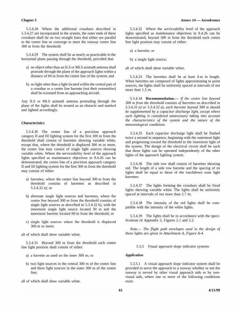
Chapter 5 Annex 14 — Aerodromes
61 4/11/99
5.3.4.28 Where the additional crossbars described in5.3.4.27 are incorporated in the system, the outer ends of thesecrossbars shall lie on two straight lines that either are parallelto the centre line or converge to meet the runway centre line300 m from the threshold.
5.3.4.29 The system shall lie as nearly as practicable in thehorizontal plane passing through the threshold, provided that:
a) no object other than an ILS or MLS azimuth antenna shallprotrude through the plane of the approach lights within adistance of 60 m from the centre line of the system; and
b) no light other than a light located within the central part ofa crossbar or a centre line barrette (not their extremities)shall be screened from an approaching aircraft.
Any ILS or MLS azimuth antenna protruding through theplane of the lights shall be treated as an obstacle and markedand lighted accordingly.
Characteristics
5.3.4.30 The centre line of a precision approachcategory II and III lighting system for the first 300 m from thethreshold shall consist of barrettes showing variable white,except that, where the threshold is displaced 300 m or more,the centre line may consist of single light sources showingvariable white. Where the serviceability level of the approachlights specified as maintenance objectives in 9.4.26 can bedemonstrated, the centre line of a precision approach categoryII and III lighting system for the first 300 m from the thresholdmay consist of either:
a) barrettes, where the centre line beyond 300 m from thethreshold consists of barrettes as described in5.3.4.32 a); or
b) alternate single light sources and barrettes, where thecentre line beyond 300 m from the threshold consists ofsingle light sources as described in 5.3.4.32 b), with theinnermost single light source located 30 m and theinnermost barrette located 60 m from the threshold; or
c) single light sources where the threshold is displaced300 m or more;
all of which shall show variable white.
5.3.4.31 Beyond 300 m from the threshold each centreline light position shall consist of either:
a) a barrette as used on the inner 300 m; or
b) two light sources in the central 300 m of the centre lineand three light sources in the outer 300 m of the centreline;
all of which shall show variable white.
5.3.4.32 Where the serviceability level of the approachlights specified as maintenance objectives in 9.4.26 can bedemonstrated, beyond 300 m from the threshold each centreline light position may consist of either:
a) a barrette; or
b) a single light source;
all of which shall show variable white.
5.3.4.33 The barrettes shall be at least 4 m in length.When barrettes are composed of lights approximating to pointsources, the lights shall be uniformly spaced at intervals of notmore than 1.5 m.
5.3.4.34 Recommendation.— If the centre line beyond300 m from the threshold consists of barrettes as described in5.3.4.31 a) or 5.3.4.32 a), each barrette beyond 300 m shouldbe supplemented by a capacitor discharge light, except wheresuch lighting is considered unnecessary taking into accountthe characteristics of the system and the nature of themeteorological conditions.
5.3.4.35 Each capacitor discharge light shall be flashedtwice a second in sequence, beginning with the outermost lightand progressing toward the threshold to the innermost light ofthe system. The design of the electrical circuit shall be suchthat these lights can be operated independently of the otherlights of the approach lighting system.
5.3.4.36 The side row shall consist of barrettes showingred. The length of a side row barrette and the spacing of itslights shall be equal to those of the touchdown zone lightbarrettes.
5.3.4.37 The lights forming the crossbars shall be fixedlights showing variable white. The lights shall be uniformlyspaced at intervals of not more than 2.7 m.
5.3.4.38 The intensity of the red lights shall be com-patible with the intensity of the white lights.
5.3.4.39 The lights shall be in accordance with the speci-fications of Appendix 2, Figures 2.1 and 2.2.
Note.— The flight path envelopes used in the design ofthese lights are given in Attachment A, Figure A-4.
5.3.5 Visual approach slope indicator systems
Application
5.3.5.1 A visual approach slope indicator system shall beprovided to serve the approach to a runway whether or not therunway is served by other visual approach aids or by non-visual aids, where one or more of the following conditionsexist:
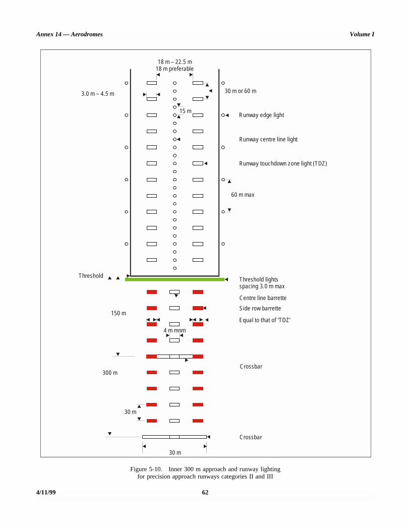
Annex 14 — Aerodromes Volume I
4/11/99 62
Figure 5-10. Inner 300 m approach and runway lightingfor precision approach runways categories II and III
18 m – 22.5 m18 m preferable
3.0 m – 4.5 m
15 m
30 m or 60 m
60 m max
Runway centre line light
Runway edge light
Runway touchdown zone light (TDZ)
Threshold Threshold lightsspacing 3.0 m max
4 m mnm
Centre line barretteSide row barrette
Equal to that of ‘TDZ’
30 m
30 m
Crossbar
Crossbar300 m
150 m
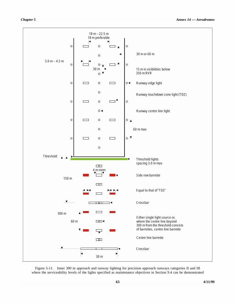
Chapter 5 Annex 14 — Aerodromes
63 4/11/99
Figure 5-11. Inner 300 m approach and runway lighting for precision approach runways categories II and IIIwhere the serviceability levels of the lights specified as maintenance objectives in Section 9.4 can be demonstrated
18 m – 22.5 m18 m preferable
3.0 m – 4.5 m
30 m
30 m or 60 m
60 m
60 m max
Runway edge light
Runway touchdown zone light (TDZ)
Runway centre line light
ThresholdThreshold lightsspacing 3.0 m max
4 m mnmSide row barrette
Either single light source or,where the centre line beyond300 m from the threshold consistsof barrettes, centre line barrette
Equal to that of ‘TDZ’
30 m
Crossbar
Crossbar
300 m
150 m
15 m in visibilities below350 m RVR
Centre line barrette
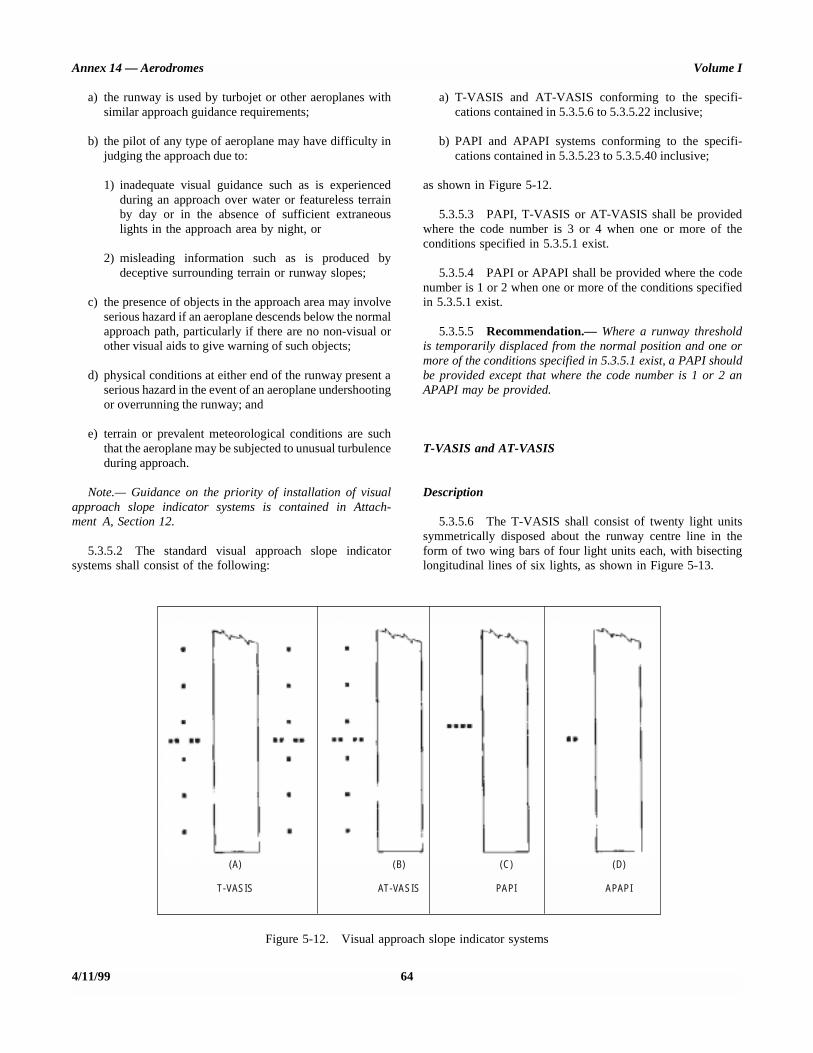
Annex 14 — Aerodromes Volume I
a) the runway is used by turbojet or other aeroplanes withsimilar approach guidance requirements;
b) the pilot of any type of aeroplane may have difficulty injudging the approach due to:
1) inadequate visual guidance such as is experiencedduring an approach over water or featureless terrainby day or in the absence of sufficient extraneouslights in the approach area by night, or
2) misleading information such as is produced bydeceptive surrounding terrain or runway slopes;
c) the presence of objects in the approach area may involveserious hazard if an aeroplane descends below the normalapproach path, particularly if there are no non-visual orother visual aids to give warning of such objects;
d) physical conditions at either end of the runway present aserious hazard in the event of an aeroplane undershootingor overrunning the runway; and
e) terrain or prevalent meteorological conditions are suchthat the aeroplane may be subjected to unusual turbulenceduring approach.
Note.— Guidance on the priority of installation of visualapproach slope indicator systems is contained in Attach-ment A, Section 12.
5.3.5.2 The standard visual approach slope indicatorsystems shall consist of the following:
a) T-VASIS and AT-VASIS conforming to the specifi-cations contained in 5.3.5.6 to 5.3.5.22 inclusive;
b) PAPI and APAPI systems conforming to the specifi-cations contained in 5.3.5.23 to 5.3.5.40 inclusive;
as shown in Figure 5-12.
5.3.5.3 PAPI, T-VASIS or AT-VASIS shall be providedwhere the code number is 3 or 4 when one or more of theconditions specified in 5.3.5.1 exist.
5.3.5.4 PAPI or APAPI shall be provided where the codenumber is 1 or 2 when one or more of the conditions specifiedin 5.3.5.1 exist.
5.3.5.5 Recommendation.— Where a runway thresholdis temporarily displaced from the normal position and one ormore of the conditions specified in 5.3.5.1 exist, a PAPI shouldbe provided except that where the code number is 1 or 2 anAPAPI may be provided.
T-VASIS and AT-VASIS
Description
5.3.5.6 The T-VASIS shall consist of twenty light unitssymmetrically disposed about the runway centre line in theform of two wing bars of four light units each, with bisectinglongitudinal lines of six lights, as shown in Figure 5-13.
4/11/99 64
Figure 5-12. Visual approach slope indicator systems
(A)
T-VASIS
(B)
AT-VASIS
(C)
PAPI
(D)
APAPI

Chapter 5 Annex 14 - Aerodromes
INSTALLATION TOLERANCES
The appropriate authority may:
vary the nominal eye height over the threshold of the on- slope signal between the limits of 12 m and 16 m, except in cases where a standard ILS glide path and/or MLS minimum glide path is available; the height over threshold should be varied to avoid any conflict between the visual approach slope indications and the usable portion of the ILS glide path and/or MLS minimum glide path indications;
vary the longitudinal distance between individual light units or the overall length of the system by not more than IO per cent;
vary the lateral displacement of the system from the runway edge by not more than + 3 m;
Note.- The system must be symmetrically displaced about the runway centre line.
d) where there is a longitudinal slope of the ground, adjust the longitudinal distance of a light unit to compensate for its difference in level from that of the threshold; and
e) where there is a transverse slope in the ground, adjust the longitudinal distance of two light units or two wing bars to compensate for the d@erence in level between them as necessary to meet the requirements of 5.3.5.16.
The distance between the wing bar and the threshold is based on an approach slope of 3” to a level runway with a nominal eye height over the threshold of 15 m. In practice, the threshold to wing bar distance is determined by:
a) the selected approach slope;
b) the longitudinal slope of the runway; and
c) the selected nominal eye height over the threshold.
Figure 5-13. Siting of light units for T-VASE
65 4/l 1199
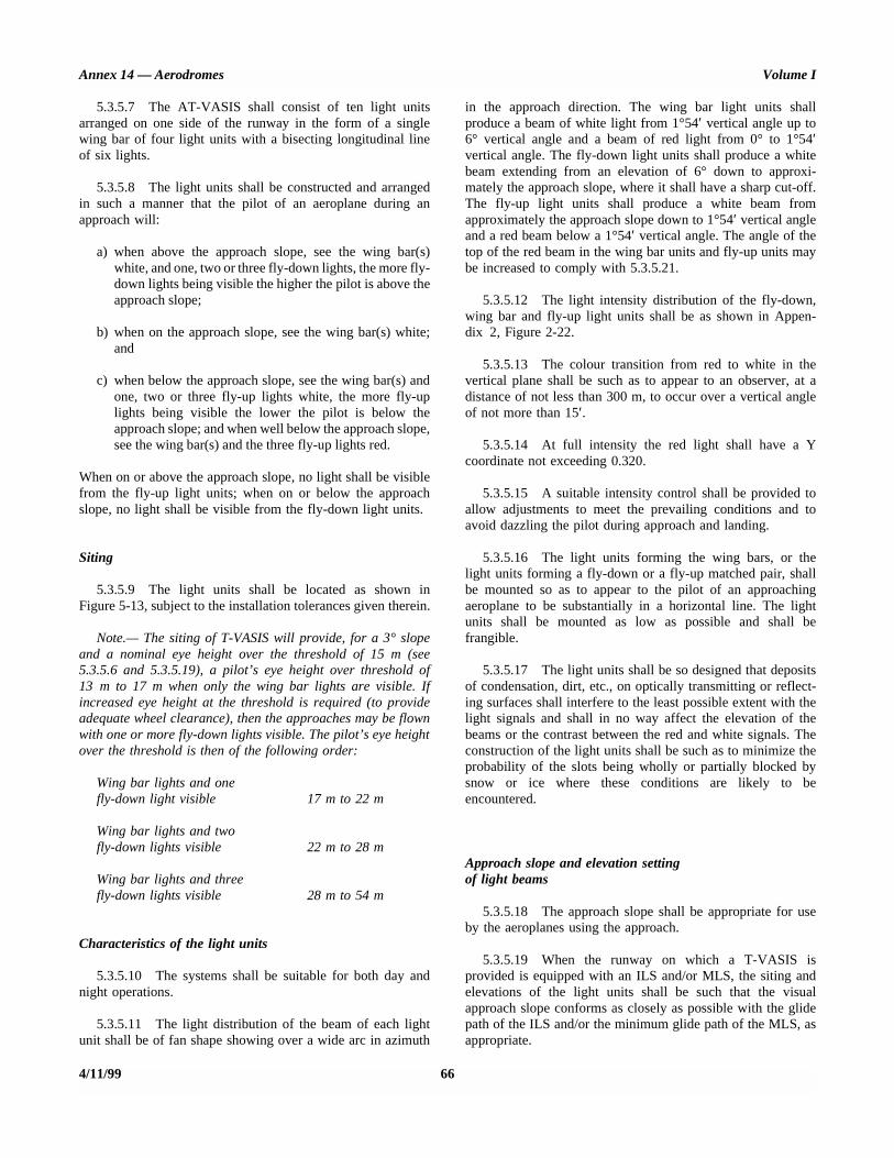
Annex 14 — Aerodromes Volume I
5.3.5.7 The AT-VASIS shall consist of ten light unitsarranged on one side of the runway in the form of a singlewing bar of four light units with a bisecting longitudinal lineof six lights.
5.3.5.8 The light units shall be constructed and arrangedin such a manner that the pilot of an aeroplane during anapproach will:
a) when above the approach slope, see the wing bar(s)white, and one, two or three fly-down lights, the more fly-down lights being visible the higher the pilot is above theapproach slope;
b) when on the approach slope, see the wing bar(s) white;and
c) when below the approach slope, see the wing bar(s) andone, two or three fly-up lights white, the more fly-uplights being visible the lower the pilot is below theapproach slope; and when well below the approach slope,see the wing bar(s) and the three fly-up lights red.
When on or above the approach slope, no light shall be visiblefrom the fly-up light units; when on or below the approachslope, no light shall be visible from the fly-down light units.
Siting
5.3.5.9 The light units shall be located as shown inFigure 5-13, subject to the installation tolerances given therein.
Note.— The siting of T-VASIS will provide, for a 3° slopeand a nominal eye height over the threshold of 15 m (see5.3.5.6 and 5.3.5.19), a pilot’s eye height over threshold of13 m to 17 m when only the wing bar lights are visible. Ifincreased eye height at the threshold is required (to provideadequate wheel clearance), then the approaches may be flownwith one or more fly-down lights visible. The pilot’s eye heightover the threshold is then of the following order:
Wing bar lights and onefly-down light visible 17 m to 22 m
Wing bar lights and twofly-down lights visible 22 m to 28 m
Wing bar lights and threefly-down lights visible 28 m to 54 m
Characteristics of the light units
5.3.5.10 The systems shall be suitable for both day andnight operations.
5.3.5.11 The light distribution of the beam of each lightunit shall be of fan shape showing over a wide arc in azimuth
in the approach direction. The wing bar light units shallproduce a beam of white light from 1°54′ vertical angle up to6° vertical angle and a beam of red light from 0° to 1°54′vertical angle. The fly-down light units shall produce a whitebeam extending from an elevation of 6° down to approxi-mately the approach slope, where it shall have a sharp cut-off.The fly-up light units shall produce a white beam fromapproximately the approach slope down to 1°54′ vertical angleand a red beam below a 1°54′ vertical angle. The angle of thetop of the red beam in the wing bar units and fly-up units maybe increased to comply with 5.3.5.21.
5.3.5.12 The light intensity distribution of the fly-down,wing bar and fly-up light units shall be as shown in Appen-dix 2, Figure 2-22.
5.3.5.13 The colour transition from red to white in thevertical plane shall be such as to appear to an observer, at adistance of not less than 300 m, to occur over a vertical angleof not more than 15′.
5.3.5.14 At full intensity the red light shall have a Ycoordinate not exceeding 0.320.
5.3.5.15 A suitable intensity control shall be provided toallow adjustments to meet the prevailing conditions and toavoid dazzling the pilot during approach and landing.
5.3.5.16 The light units forming the wing bars, or thelight units forming a fly-down or a fly-up matched pair, shallbe mounted so as to appear to the pilot of an approachingaeroplane to be substantially in a horizontal line. The lightunits shall be mounted as low as possible and shall befrangible.
5.3.5.17 The light units shall be so designed that depositsof condensation, dirt, etc., on optically transmitting or reflect-ing surfaces shall interfere to the least possible extent with thelight signals and shall in no way affect the elevation of thebeams or the contrast between the red and white signals. Theconstruction of the light units shall be such as to minimize theprobability of the slots being wholly or partially blocked bysnow or ice where these conditions are likely to beencountered.
Approach slope and elevation setting of light beams
5.3.5.18 The approach slope shall be appropriate for useby the aeroplanes using the approach.
5.3.5.19 When the runway on which a T-VASIS isprovided is equipped with an ILS and/or MLS, the siting andelevations of the light units shall be such that the visualapproach slope conforms as closely as possible with the glidepath of the ILS and/or the minimum glide path of the MLS, asappropriate.
4/11/99 66
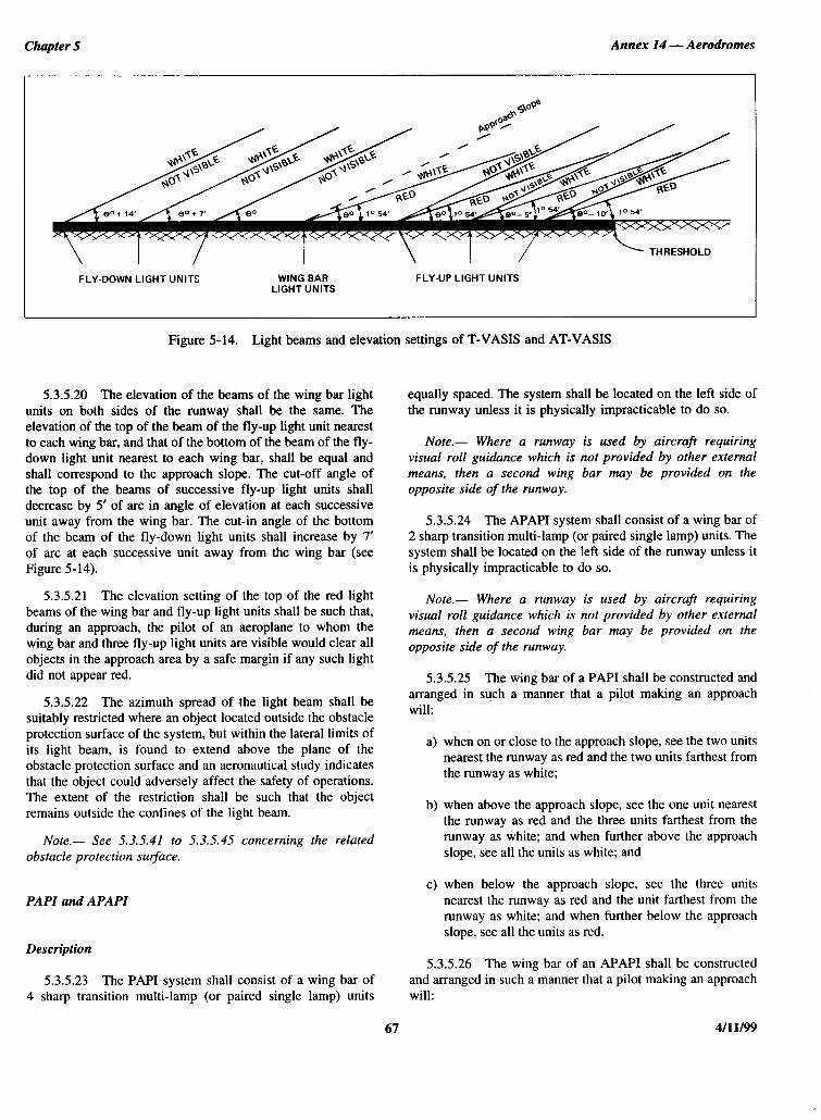
Chapter 5 Annex I4 - Aerodromes
FLY-DOWN LIGHT UNITS WiNG BAR LIGHT UNITS
FLY-UP LIGHT UNITS
Figure 5-14. Light beams and elevation settings of T-VASE and AT-VASIS
53.520 The elevation of the beams of the wing bar light units on both sides of the runway shall be the same. The elevation of the top of the beam of the fly-up light unit nearest to each wing bar, and that of the bottom of the beam of the fly- down light unit nearest to each wing bar, shall be equal and shall correspond to the approach slope. The cut-off angle of the top of the beams of successive fly-up light units shall decrease by 5’ of arc in angle of elevation at each successive unit away from the wing bar. The cut-in angle of the bottom of the beam of the fly-down light units shall increase by 7’ of arc at each successive unit away from the wing bar (see Figure 5-14).
5.3.5.21 The elevation setting of the top of the red light beams of the wing bar and fly-up light units shall be such that, during an approach, the pilot of an aeroplane to whom the wing bar and three fly-up light units are visible would clear all objects in the approach area by a safe margin if any such light did not appear red.
5.3.5.22 The azimuth spread of the light beam shall be suitably restricted where an object located outside the obstacle protection surface of the system, but within the lateral limits of its light beam, is found to extend above the plane of the obstacle protection surface and an aeronautical study indicates that the object could adversely affect the safety of operations. The extent of the restriction shall be such that the object remains outside the confines of the light beam.
Note.- See 5.3.5.41 to X3.5.45 concerning the related obstacle protection sur$ace.
PAPI and APAPl
Description
5.3.5.23 The PAP1 system shall consist of a wing bar of 4 sharp transition multi-lamp (or paired single lamp) units
equally spaced. The system shall be located on the left side of the runway unless it is physically impracticable to do so.
Note.- Where a runway is used by aircraft requiring visual roll guidance which is not provided by other external means, then a second wing bar may be provided on the opposite side of the runway.
5.3.5.24 The APAPI system shall consist of a wing bar of 2 sharp transition multi-lamp (or paired single lamp) units. The system shall be located on the left side of the runway unless it is physically impracticable to do so.
Note.- Where a runway is used by aircrafr requiring visual roll guidance which is not provided by other external means, then a second wing bar may be provided on the opposite side of the runway.
5.3.5.25 The wing bar of a PAP1 shall be constructed and arranged in such a manner that a pilot making an approach will:
a) when on or close to the approach slope, see the two units nearest the runway as red and the two units farthest from the runway as white;
b) when above the approach slope, see the one unit nearest the runway as red and the three units farthest from the runway as white; and when further above the approach slope, see all the units as white; and
c) when below the approach slope, see the three units nearest the runway as red and the unit farthest from the runway as white; and when further below the approach slope, see all the units as red.
5.3.5.26 The wing bar of an APAPI shall be constructed and arranged in such a manner that a pilot making an approach will:
67 4/l 1199

Annex I4 - Aerodromes
a) when on or close to the approach slope, see the unit nearer the runway as red and the unit farther from the runway as white;
b) when above the approach slope, see both the units as white; and
c) when below the approach slope, see both the units as red.
Siting
5.3.5.27 The light units shall be located as in the basic configuration illustrated in Figure 5-15, subject to the instal- lation tolerances given therein. The units forming a wing bar shall be mounted so as to appear to the pilot of an approaching aeroplane to be substantially in a horizontal line. The light units shall be mounted as low as possible and shall be frangible.
Characteristics of the light units
5.3.5.28 The system shall be suitable for both day and night operations.
5.3.5.29 The colour transition from red to white in the vertical plane shall be such as to appear to an observer, at a distance of not less than 300 m, to occur within a vertical angle of not more than 3’.
5.3.5.30 At full intensity the red light shall have a Y coordinate not exceeding 0.320.
5.3.5.31 The light intensity distribution of the light units shall be as shown in Appendix 2, Figure 2.23.
Note.- See the Aerodrome Design Manual, Part 4 for additional guidance on the characteristics of light units.
5.3.5.32 Suitable intensity control shall be provided so as to allow adjustment to meet the prevailing conditions and to avoid dazzling the pilot during approach and landing.
5.3.5.33 Each light unit shall be capable of adjustment in elevation so that the lower limit of the white part of the beam may be fixed at any desired angle of elevation between l”30’ and at least 4”30’ above the horizontal.
5.3.5.34 The light units shall be so designed that deposits of condensation, snow, ice, dirt, etc., on optically transmitting or reflecting surfaces shall interfere to the least possible extent with the light signals and shall not affect the contrast between the red and white signals and the elevation of the transition sector.
Volume I
Approach slope and elevation setting of light units
5.3.5.35 The approach slope as defined in Figure 5-16 shall be appropriate for use by the aeroplanes using the approach.
5.3.5.36 When the runway is equipped with an ILS and/or MLS, the siting and the angle of elevation of the light units shall be such that the visual approach slope conforms as closely as possible with the glide path of the ILS and/or the minimum glide path of the MLS, as appropriate.
5.3.5.37 The angle of elevation settings of the light units in a PAP1 wing bar shall be such that, during an approach, the pilot of an aeroplane observing a signal of one white and three reds will clear all objects in the approach area by a safe margin.
5.3.5.38 The angle of elevation settings of the light units in an APAPI wing bar shall be such that, during an approach, the pilot of an aeroplane observing the lowest onslope signal, i.e. one white and one red, will clear all objects in the approach area by a safe margin.
5.3.5.39 The azimuth spread of the light beam shall be suitably restricted where an object located outside the obstacle protection surface of the PAP1 or APAPI system, but within the lateral limits of its light beam, is found to extend above the plane of the obstacle protection surface and an aeronautical study indicates that the object could adversely affect the safety of operations. The extent of the restriction shall be such that the object remains outside the confines of the light beam.
Note.- See 5.3.5.41 to 5.3.5.45 concerning the related obstacle protection surface.
5.3.5.40 Where wing bars are installed on each side of the runway to provide roll guidance, corresponding units shall be set at the same angle so that the signals of each wing bar change symmetrically at the same time.
Obstacle protection surface
Note.- The following specifications apply to T-VASIS, AT-VASIS, PAPI and APAPI.
5.3.5.41 An obstacle protection surface shall be estab- lished when it is intended to provide a visual approach slope indicator system.
5.3.5.42 The characteristics of the obstacle protection surface, i.e. origin, divergence, length and slope shall corre- spond to those specified in the relevant column of Table 5-3 and in Figure 5-17.
411 l/99 68

Chupter 5 Annex 14 - Aerodromes
RUNWAY
\
15m ‘ (2 1 m)
TYPICAL PAPI WING BAR
RUNWAY P Y
z
TYPICAL APAPI WING BAR
INSTALLATION TOLERANCES
Where a PAPI or APAPI is installed on a runway not equipped with an ILS or MLS, the distance Dt shall be calculated to ensure that the lowest height at which a pilot will see a correct approach path indication (Figure 5-16, angle B for a PAPI and angle A for an APAPI) provides the wheel clearance over the threshold specified in Table 5-2 for the most demanding amongst aeroplanes regularly using the runway.
Where a PAPI or APAPI is installed on a runway equipped with an ILS and/or MLS, the distance Dr shall be calculated to provide the optimum compatibility between the visual and non- visual aids for the range of eye-to-antenna heights of the aeroplanes regularly using the runway. The distance shall be equal to that between the threshold and the effective origin of the ILS glide path or MLS minimum glide path, as appropriate, plus a correction factor for the variation of eye-to-antenna heights of the aeroplanes concerned. The correction factor is obtained by multiplying the average eye-to-antenna height of those aeroplanes by the cotangent of the approach angle. However, the distance shall be such that in no case will the wheel clearance over the threshold be lower than that specified in column (3) of Table 5-2.
Note.- See Section 5.2.5 for specifications on aiming point marking. Guidance on the harmonization of PAPI, ILS and/or MLS signals is contained in the Aerodrome Design Manual, Part 4.
4
4
4
f9
If a wheel clearance, greater than that specified in a) above is required for specific aircraft, this can be achieved by increasing Dt.
Distance D, shall be adjusted to compensate for differences in elevation between the lens centres of the light units and the threshold.
To ensure that units are mounted as low as possible and to allow for any transverse slope, small height adjustments of up to 5 cm between units are acceptable. A lateral gradient not greater that 1.25 per cent can be accepted provided it is uniformly applied across the units.
A spacing of 6 m (iI m) between PAPI units should be used on code numbers I and 2. In such an event, the inner PAPI unit shall be located not less than IO m (21 m) from the runway edge.
Note.- Reducing the spacing between light units results in a reduction in usable range of the system.
g) The lateral spacing between APAPI units may be increased to 9 m (*I m) if greater range is required or later conversion to a fill PAPI is anticipated. In the latter case, the inner APAPI unit shall be located 15 m (*I m) from the runway edge.
J Figure 5-1.5 Siting of PAP1 and APAPI
69 4/l l/99

Annex 14 - Aerodromes Volume I
PAPI WiNG BAR THRESHOLD
The height of the pilots eye above the aircraft’s ILS glide path/MLS antenna varies with the type of aeroplane and approach attitude. Harmonization of the PAPI signal and ILS glide path and/or MLS minimum glide path to a point closer to the threshold may be achieved by increasing the on-course sector from 20’ to 30’. The setting angles for a 3” glide slope would then be 2”25’, 2”45’. 375 and 3”35’.
A - 3” PAPI ILLUSTRATED
APAPI WING BAR THRESHOLD
B - 3” APAPI ILLUSTRATED
4/l l/99
Figure 5-16. Light beams and angle of elevation setting of PAP1 and APAPI
70
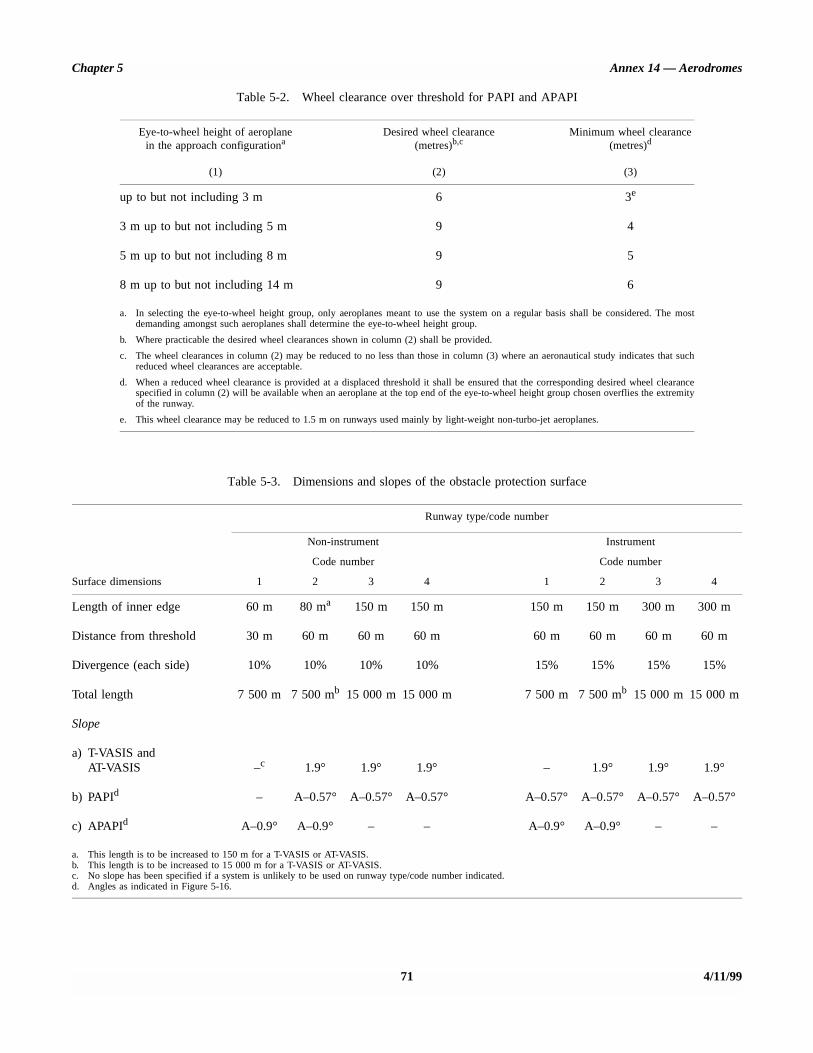
Chapter 5 Annex 14 — Aerodromes
71 4/11/99
Table 5-2. Wheel clearance over threshold for PAPI and APAPI
Table 5-3. Dimensions and slopes of the obstacle protection surface
Eye-to-wheel height of aeroplanein the approach configurationa
(1)
Desired wheel clearance(metres)b,c
(2)
Minimum wheel clearance(metres)d
(3)
up to but not including 3 m 6 3e
3 m up to but not including 5 m 9 4
5 m up to but not including 8 m 9 5
8 m up to but not including 14 m 9 6
a. In selecting the eye-to-wheel height group, only aeroplanes meant to use the system on a regular basis shall be considered. The mostdemanding amongst such aeroplanes shall determine the eye-to-wheel height group.
b. Where practicable the desired wheel clearances shown in column (2) shall be provided.
c. The wheel clearances in column (2) may be reduced to no less than those in column (3) where an aeronautical study indicates that suchreduced wheel clearances are acceptable.
d. When a reduced wheel clearance is provided at a displaced threshold it shall be ensured that the corresponding desired wheel clearancespecified in column (2) will be available when an aeroplane at the top end of the eye-to-wheel height group chosen overflies the extremityof the runway.
e. This wheel clearance may be reduced to 1.5 m on runways used mainly by light-weight non-turbo-jet aeroplanes.
Runway type/code number
Non-instrument
Code number
Instrument
Code number
Surface dimensions 1 2 3 4 1 2 3 4
Length of inner edge 60 m 80 ma 150 m 150 m 150 m 150 m 300 m 300 m
Distance from threshold 30 m 60 m 60 m 60 m 60 m 60 m 60 m 60 m
Divergence (each side) 10% 10% 10% 10% 15% 15% 15% 15%
Total length 7 500 m 7 500 mb 15 000 m 15 000 m 7 500 m 7 500 mb 15 000 m 15 000 m
Slope
a) T-VASIS andAT-VASIS –c 1.9° 1.9° 1.9° – 1.9° 1.9° 1.9°
b) PAPId – A–0.57° A–0.57° A–0.57° A–0.57° A–0.57° A–0.57° A–0.57°
c) APAPId A–0.9° A–0.9° – – A–0.9° A–0.9° – –
a. This length is to be increased to 150 m for a T-VASIS or AT-VASIS.b. This length is to be increased to 15 000 m for a T-VASIS or AT-VASIS.c. No slope has been specified if a system is unlikely to be used on runway type/code number indicated.d. Angles as indicated in Figure 5-16.

Annex 14 - Aerodromes Volume I
-------_
Approach surface inner edge
Obstacle protection surface
I I I I I I
/ ‘\ Threshold Approach surface inner edge
Section A-A
Figure 5-17. Obstacle protection surface for visual approach slope indicator systems
5.3.5.43 New objects or extensions of existing objects shall not be permitted above an obstacle protection surface except when, in the opinion of the appropriate authority, the new object or extension would be shielded by an existing immovable object.
5.3.5.45 Where an aeronautical study indicates that an existing object extending above an obstacle protection surface could adversely affect the safety of operations of aeroplanes one or more of the following measures shall be taken:
Note.- Circumstances in which the shielding principle may reasonably be applied are described in the Airport Services Manual, Part 6.
5.3.5.44 Existing objects above an obstacle protection
a)
b)
surface shall be removed except when, in the opinion of the appropriate authority, the object is shielded by an existing c>
immovable object, or after aeronautical study it is determined that the object would not adversely affect the safety of operations of aeroplanes. d)
4/l l/99 72
suitably raise the approach slope of the system;
reduce the azimuth spread of the system so that the object is outside the confines of the beam;
displace the axis of the system and its associated obstacle protection surface by no more than 5”;
suitably displace the threshold; and

Chapter 5 Annex 14 — Aerodromes
e) where d) is found to be impracticable, suitably displacethe system upwind of the threshold to provide an increasein threshold crossing height equal to the height of theobject penetration.
Note.— Guidance on this issue is contained in theAerodrome Design Manual, Part 4.
5.3.6 Circling guidance lights
Application
5.3.6.1 Recommendation.— Circling guidance lightsshould be provided when existing approach and runwaylighting systems do not satisfactorily permit identification ofthe runway and/or approach area to a circling aircraft in theconditions for which it is intended the runway be used forcircling approaches.
Location
5.3.6.2 Recommendation.— The location and number ofcircling guidance lights should be adequate to enable a pilot,as appropriate, to:
a) join the downwind leg or align and adjust the aircraft’strack to the runway at a required distance from it and todistinguish the threshold in passing; and
b) keep in sight the runway threshold and/or other featureswhich will make it possible to judge the turn on to baseleg and final approach, taking into account the guidanceprovided by other visual aids.
5.3.6.3 Recommendation.— Circling guidance lightsshould consist of:
a) lights indicating the extended centre line of the runwayand/or parts of any approach lighting system; or
b) lights indicating the position of the runway threshold; or
c) lights indicating the direction or location of the runway;
or a combination of such lights as is appropriate to therunway under consideration.
Note.— Guidance on installation of circling guidance lightsis given in the Aerodrome Design Manual, Part 4.
Characteristics
5.3.6.4 Recommendation.— Circling guidance lightsshould be fixed or flashing lights of an intensity and beamspread adequate for the conditions of visibility and ambient
light in which it is intended to make visual circlingapproaches. The flashing lights should be white, and thesteady lights either white or gaseous discharge lights.
5.3.6.5 Recommendation.— The lights should bedesigned and be installed in such a manner that they will notdazzle or confuse a pilot when approaching to land, taking offor taxiing.
5.3.7 Runway lead-in lighting systems
Application
5.3.7.1 Recommendation.— A runway lead-in lightingsystem should be provided where it is desired to provide visualguidance along a specific approach path, for reasons such asavoiding hazardous terrain or for purposes of noiseabatement.
Note.— Guidance on providing lead-in lighting systems isgiven in the Aerodrome Design Manual, Part 4.
Location
5.3.7.2 Recommendation.— A runway lead-in lightingsystem should consist of groups of lights positioned so as todefine the desired approach path and so that one group maybe sighted from the preceding group. The interval betweenadjacent groups should not exceed approximately 1 600 m.
Note.— Runway lead-in lighting systems may be curved,straight or a combination thereof.
5.3.7.3 Recommendation.— A runway lead-in lightingsystem should extend from a point as determined by theappropriate authority, up to a point where the approachlighting system, if provided, or the runway or the runwaylighting system is in view.
Characteristics
5.3.7.4 Recommendation.— Each group of lights of arunway lead-in lighting system should consist of at least threeflashing lights in a linear or cluster configuration. The systemmay be augmented by steady burning lights where such lightswould assist in identifying the system.
5.3.7.5 Recommendation.— The flashing lights shouldbe white, and the steady burning lights gaseous dischargelights.
5.3.7.6 Recommendation.— Where practicable, theflashing lights in each group should flash in sequence towardsthe runway.
73 4/11/99

Annex 14 — Aerodromes Volume I
5.3.8 Runway threshold identification lights
Application
5.3.8.1 Recommendation.— Runway threshold identi-fication lights should be installed:
a) at the threshold of a non-precision approach runwaywhen additional threshold conspicuity is necessary orwhere it is not practicable to provide other approachlighting aids; and
b) where a runway threshold is permanently displaced fromthe runway extremity or temporarily displaced from thenormal position and additional threshold conspicuity isnecessary.
Location
5.3.8.2 Runway threshold identification lights shall belocated symmetrically about the runway centre line, in linewith the threshold and approximately 10 m outside each lineof runway edge lights.
Characteristics
5.3.8.3 Recommendation.— Runway threshold identi-fication lights should be flashing white lights with a flashfrequency between 60 and 120 per minute.
5.3.8.4 The lights shall be visible only in the direction ofapproach to the runway.
5.3.9 Runway edge lights
Application
5.3.9.1 Runway edge lights shall be provided for arunway intended for use at night or for a precision approachrunway intended for use by day or night.
5.3.9.2 Recommendation.— Runway edge lights shouldbe provided on a runway intended for take-off with anoperating minimum below an RVR of the order of 800 m byday.
Location
5.3.9.3 Runway edge lights shall be placed along the fulllength of the runway and shall be in two parallel rows equi-distant from the centre line.
5.3.9.4 Runway edge lights shall be placed along theedges of the area declared for use as the runway or outside theedges of the area at a distance of not more than 3 m.
5.3.9.5 Recommendation.— Where the width of the areawhich could be declared as runway exceeds 60 m, the distancebetween the rows of lights should be determined taking intoaccount the nature of the operations, the light distributioncharacteristics of the runway edge lights, and other visual aidsserving the runway.
5.3.9.6 The lights shall be uniformly spaced in rows atintervals of not more than 60 m for an instrument runway, andat intervals of not more than 100 m for a non-instrumentrunway. The lights on opposite sides of the runway axis shallbe on lines at right angles to that axis. At intersections ofrunways, lights may be spaced irregularly or omitted, providedthat adequate guidance remains available to the pilot.
Characteristics
5.3.9.7 Runway edge lights shall be fixed lights showingvariable white, except that:
a) in the case of a displaced threshold, the lights between thebeginning of the runway and the displaced threshold shallshow red in the approach direction; and
b) a section of the lights 600 m or one-third of the runwaylength, whichever is the less, at the remote end of therunway from the end at which the take-off run is started,may show yellow.
5.3.9.8 The runway edge lights shall show at all angles inazimuth necessary to provide guidance to a pilot landing ortaking off in either direction. When the runway edge lights areintended to provide circling guidance, they shall show at allangles in azimuth (see 5.3.6.1).
5.3.9.9 In all angles of azimuth required in 5.3.9.8,runway edge lights shall show at angles up to 15° above thehorizontal with an intensity adequate for the conditions ofvisibility and ambient light in which use of the runway fortake-off or landing is intended. In any case, the intensity shallbe at least 50 cd except that at an aerodrome withoutextraneous lighting the intensity of the lights may be reducedto not less than 25 cd to avoid dazzling the pilot.
5.3.9.10 Runway edge lights on a precision approachrunway shall be in accordance with the specifications ofAppendix 2, Figure 2-9 or 2-10.
5.3.10 Runway threshold and wing bar lights(see Figure 5-18)
Application of runway threshold lights
5.3.10.1 Runway threshold lights shall be provided for arunway equipped with runway edge lights except on a non-instrument or non-precision approach runway where thethreshold is displaced and wing bar lights are provided.
4/11/99 74

cuter 5 Annex 14 - Aemdromes

Annex 14 — Aerodromes Volume I
Location of runway threshold lights
5.3.10.2 When a threshold is at the extremity of arunway, the threshold lights shall be placed in a row at rightangles to the runway axis as near to the extremity of therunway as possible and, in any case, not more than 3 m outsidethe extremity.
5.3.10.3 When a threshold is displaced from the extremityof a runway, threshold lights shall be placed in a row at rightangles to the runway axis at the displaced threshold.
5.3.10.4 Threshold lighting shall consist of:
a) on a non-instrument or non-precision approach runway,at least six lights;
b) on a precision approach runway category I, at least thenumber of lights that would be required if the lights wereuniformly spaced at intervals of 3 m between the rows ofrunway edge lights; and
c) on a precision approach runway category II or III, lightsuniformly spaced between the rows of runway edge lightsat intervals of not more than 3 m.
5.3.10.5 Recommendation.— The lights prescribed in5.3.10.4 a) and b) should be either:
a) equally spaced between the rows of runway edge lights,or
b) symmetrically disposed about the runway centre line intwo groups, with the lights uniformly spaced in eachgroup and with a gap between the groups equal to thegauge of the touchdown zone marking or lighting, wheresuch is provided, or otherwise not more than half thedistance between the rows of runway edge lights.
Application of wing bar lights
5.3.10.6 Recommendation.— Wing bar lights should beprovided on a precision approach runway when additionalconspicuity is considered desirable.
5.3.10.7 Wing bar lights shall be provided on a non-instrument or non-precision approach runway where thethreshold is displaced and runway threshold lights arerequired, but are not provided.
Location of wing bar lights
5.3.10.8 Wing bar lights shall be symmetrically disposedabout the runway centre line at the threshold in two groups, i.e.wing bars. Each wing bar shall be formed by at least five lightsextending at least 10 m outward from, and at right angles to,the line of the runway edge lights, with the innermost light ofeach wing bar in the line of the runway edge lights.
Characteristics of runway threshold and wing bar lights
5.3.10.9 Runway threshold and wing bar lights shall befixed unidirectional lights showing green in the direction ofapproach to the runway. The intensity and beam spread of thelights shall be adequate for the conditions of visibility andambient light in which use of the runway is intended.
5.3.10.10 Runway threshold lights on a precision ap-proach runway shall be in accordance with the specificationsof Appendix 2, Figure 2.3.
5.3.10.11 Threshold wing bar lights on a precision ap-proach runway shall be in accordance with the specificationsof Appendix 2, Figure 2.4.
5.3.11 Runway end lights(see Figure 5-18)
Application
5.3.11.1 Runway end lights shall be provided for a run-way equipped with runway edge lights.
Note.— When the threshold is at the runway extremity,fittings serving as threshold lights may be used as runway endlights.
Location
5.3.11.2 Runway end lights shall be placed on a line atright angles to the runway axis as near to the end of therunway as possible and, in any case, not more than 3 m outsidethe end.
5.3.11.3 Recommendation.— Runway end lightingshould consist of at least six lights. The lights should be either:
a) equally spaced between the rows of runway edge lights,or
b) symmetrically disposed about the runway centre line intwo groups with the lights uniformly spaced in eachgroup and with a gap between the groups of not morethan half the distance between the rows of runway edgelights.
For a precision approach runway category III, the spacingbetween runway end lights, except between the two innermostlights if a gap is used, should not exceed 6 m.
Characteristics
5.3.11.4 Runway end lights shall be fixed unidirectionallights showing red in the direction of the runway. The intensity
4/11/99 76
Chapter 5 Annex 14 — Aerodromes
and beam spread of the lights shall be adequate for theconditions of visibility and ambient light in which use of therunway is intended.
5.3.11.5 Runway end lights on a precision approach run-way shall be in accordance with the specifications of Appen-dix 2, Figure 2-8.
5.3.12 Runway centre line lights
Application
5.3.12.1 Runway centre line lights shall be provided on aprecision approach runway category II or III.
5.3.12.2 Recommendation.— Runway centre line lightsshould be provided on a precision approach runway categoryI, particularly when the runway is used by aircraft with highlanding speeds or where the width between the runway edgelights is greater than 50 m.
5.3.12.3 Runway centre line lights shall be provided on arunway intended to be used for take-off with an operatingminimum below an RVR of the order of 400 m.
5.3.12.4 Recommendation.— Runway centre line lightsshould be provided on a runway intended to be used fortake-off with an operating minimum of an RVR of the order of400 m or higher when used by aeroplanes with a very hightake-off speed, particularly where the width between therunway edge lights is greater than 50 m.
Location
5.3.12.5 Runway centre line lights shall be located alongthe centre line of the runway, except that the lights may beuniformly offset to the same side of the runway centre line bynot more than 60 cm where it is not practicable to locate themalong the centre line. The lights shall be located from thethreshold to the end at longitudinal spacing of approximately15 m. Where the serviceability level of the runway centre linelights specified as maintenance objectives in 9.4.26 or 9.4.30,as appropriate, can be demonstrated and the runway isintended for use in runway visual range conditions of 350 mor greater, the longitudinal spacing may be approximately30 m.
Note.— Existing centre line lighting where lights are spacedat 7.5 m need not be replaced.
5.3.12.6 Recommendation.— Centre line guidance fortake-off from the beginning of a runway to a displacedthreshold should be provided by:
a) an approach lighting system if its characteristics andintensity settings afford the guidance required duringtake-off and it does not dazzle the pilot of an aircrafttaking off; or
b) runway centre line lights; or
c) barrettes of at least 3 m length and spaced at uniformintervals of 30 m, as shown in Figure 5-19, designed sothat their photometric characteristics and intensitysetting afford the guidance required during take-offwithout dazzling the pilot of an aircraft taking off.
Where necessary, provision should be made to extinguishthose centre line lights specified in b) or reset the intensity ofthe approach lighting system or barrettes when the runway isbeing used for landing. In no case should only the singlesource runway centre line lights show from the beginning ofthe runway to a displaced threshold when the runway is beingused for landing.
Characteristics
5.3.12.7 Runway centre line lights shall be fixed lightsshowing variable white from the threshold to the point 900 mfrom the runway end; alternate red and variable white from900 m to 300 m from the runway end; and red from 300 m tothe runway end, except that for runways less than 1 800 m inlength, the alternate red and variable white lights shall extendfrom the mid-point of the runway usable for landing to 300 mfrom the runway end.
Note.— Care is required in the design of the electricalsystem to ensure that failure of part of the electrical systemwill not result in a false indication of the runway distanceremaining.
5.3.12.8 Runway centre line lights shall be in accordancewith the specifications of Appendix 2, Figure 2.6 or 2.7.
5.3.13 Runway touchdown zone lights
Application
5.3.13.1 Touchdown zone lights shall be provided in thetouchdown zone of a precision approach runway category IIor III.
Location
5.3.13.2 Touchdown zone lights shall extend from thethreshold for a longitudinal distance of 900 m, except that,on runways less than 1 800 m in length, the system shall beshortened so that it does not extend beyond the midpoint of therunway. The pattern shall be formed by pairs of barrettessymmetrically located about the runway centre line. The
77 4/11/99
Annex 14 — Aerodromes Volume I
lateral spacing between the innermost lights of a pair ofbarrettes shall be equal to the lateral spacing selected for thetouchdown zone marking. The longitudinal spacing betweenpairs of barrettes shall be either 30 m or 60 m.
Note.— To allow for operations at lower visibility minima,it may be advisable to use a 30 m longitudinal spacingbetween barrettes.
Characteristics
5.3.13.3 A barrette shall be composed of at least threelights with a spacing between the lights of not more than1.5 m.
5.3.13.4 Recommendation.— A barrette should be notless than 3 m nor more than 4.5 m in length.
5.3.13.5 Touchdown zone lights shall be fixed uni-directional lights showing variable white.
5.3.13.6 Touchdown zone lights shall be in accordancewith the specifications of Appendix 2, Figure 2.5.
5.3.14 Stopway lights
Application
5.3.14.1 Stopway lights shall be provided for a stopwayintended for use at night.
Location
5.3.14.2 Stopway lights shall be placed along the fulllength of the stopway and shall be in two parallel rows that areequidistant from the centre line and coincident with the rowsof the runway edge lights. Stopway lights shall also be pro-vided across the end of a stopway on a line at right angles tothe stopway axis as near to the end of the stopway as possibleand, in any case, not more than 3 m outside the end.
Characteristics
5.3.14.3 Stopway lights shall be fixed unidirectionallights showing red in the direction of the runway.
5.3.15 Taxiway centre line lights
Application
5.3.15.1 Taxiway centre line lights shall be provided onan exit taxiway, taxiway, de-icing/anti-icing facility and apronintended for use in runway visual range conditions less than a
value of 350 m in such a manner as to provide continuousguidance between the runway centre line and aircraft stands,except that these lights need not be provided where the trafficdensity is light and taxiway edge lights and centre linemarking provide adequate guidance.
5.3.15.2 Recommendation.— Taxiway centre line lightsshould be provided on a taxiway intended for use at night inrunway visual range conditions of 350 m or greater, andparticularly on complex taxiway intersections and exittaxiways, except that these lights need not be provided wherethe traffic density is light and taxiway edge lights and centreline marking provide adequate guidance.
Note.— Where there may be a need to delineate the edgesof a taxiway, e.g. on a rapid exit taxiway, narrow taxiway orin snow conditions, this may be done with taxiway edge lightsor markers.
5.3.15.3 Recommendation.— Taxiway centre line lightsshould be provided on an exit taxiway, taxiway, de-icing/anti-icing facility and apron in all visibility conditions wherespecified as components of an advanced surface movementguidance and control system in such a manner as to providecontinuous guidance between the runway centre line andaircraft stands.
5.3.15.4 Taxiway centre line lights shall be provided on arunway forming part of a standard taxi-route and intended fortaxiing in runway visual range conditions less than a value of350 m, except that these lights need not be provided where thetraffic density is light and taxiway edge lights and centre linemarking provide adequate guidance.
Note.— See 8.2.3 for provisions concerning the interlockingof runway and taxiway lighting systems.
5.3.15.5 Recommendation.— Taxiway centre line lightsshould be provided in all visibility conditions on a runwayforming part of a standard taxi-route where specified ascomponents of an advanced surface movement guidance andcontrol system.
Characteristics
5.3.15.6 Taxiway centre line lights on a taxiway otherthan an exit taxiway and on a runway forming part of astandard taxi-route shall be fixed lights showing green withbeam dimensions such that the light is visible only fromaeroplanes on or in the vicinity of the taxiway.
5.3.15.7 Taxiway centre line lights on an exit taxiwayshall be fixed lights. Alternate taxiway centre line lights shallshow green and yellow from their beginning near the runwaycentre line to the perimeter of the ILS/MLS critical/sensitivearea or the lower edge of the inner transitional surface,whichever is farthest from the runway; and thereafter all lightsshall show green (Figure 5-20). The light nearest to theperimeter shall always show yellow. Where aircraft may
4/11/99 781/11/01
No. 4
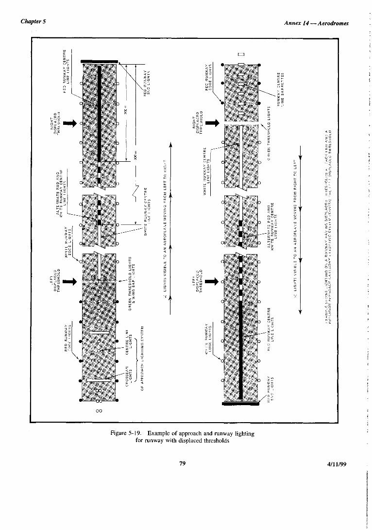
0
0
‘\’
” -
- ‘\
” ”
-/-
-
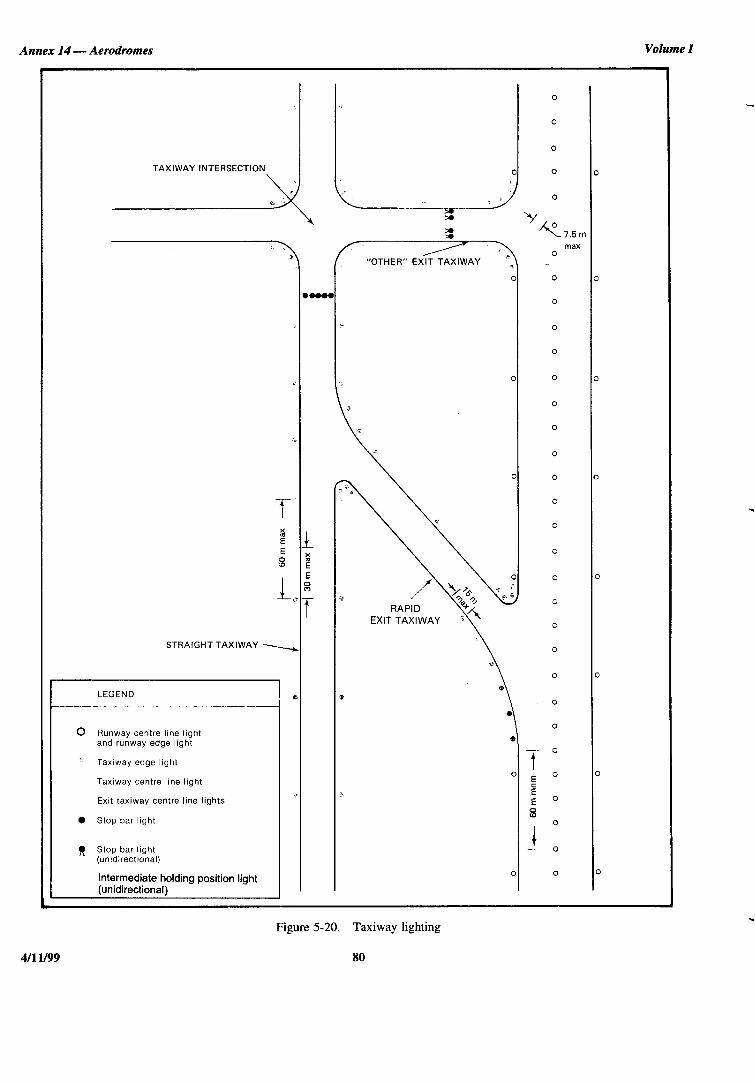
Annex 14 - Aerodromes Volume I
0
0
0
TAXIWAY INTERSECTION 0 0 0
0
M M
3 ‘Y~7.5m
max
“OTHER” EXIT TAXIWAY *, 0
0 0 0
l oo.0 0
0
0
0 0 0
0
0 0 0
f 0
0
f f
8 2
0
I E 0 0
a
.L f
0
0
STRAIGHT TAXIWAY - 0
0 0
LEGEND a: 0
0 0 runway light
centre line
and runway edge light
Taxiway edge light 7-O 0
Taxiway centre line light E ’ 0
+f 0 E
Exit taxiway centre line lights E O
0 Stop bar light 8
0
R Stop bar light (unidirectional) Intermediate holding position light
(unidirectional)
1 - 0
0 0 0
Figure S-20. Taxiway lighting
80

Chapter 5 Annex 14 — Aerodromes
follow the same centre line in both directions, all the centreline lights shall show green to aircraft approaching the runway.
Note 1.— Care is necessary to limit the light distribution ofgreen lights on or near a runway so as to avoid possibleconfusion with threshold lights.
Note 2.— For yellow filter characteristics see Appendix 1,2.2.
Note 3.— The size of the ILS/MLS critical/sensitive areadepends on the characteristics of the associated ILS/MLS andother factors. Guidance is provided in Annex 10, Volume I,Attachments C and G to Part I.
Note 4.— See 5.4.3 for specifications on runway vacatedsigns.
5.3.15.8 Taxiway centre line lights shall be in accordancewith the specifications of:
a) Appendix 2, Figure 2-12, 2-13, or 2-14 for taxiwaysintended for use in runway visual range conditions ofless than a value of 350 m; and
b) Appendix 2, Figure 2-15 or 2-16 for other taxiways.
5.3.15.9 Recommendation.— Where taxiway centre linelights are specified as components of an advanced surfacemovement guidance and control system and where, from anoperational point of view, higher intensities are required tomaintain ground movements at a certain speed in very lowvisibilities or in bright daytime conditions, taxiway centre linelights should be in accordance with the specifications ofAppendix 2, Figure 2-17, 2-18 or 2-19.
Note.— High-intensity centre line lights should only beused in case of an absolute necessity and following a specificstudy.
Location
5.3.15.10 Recommendation.— Taxiway centre line lightsshould normally be located on the taxiway centre line marking,except that they may be offset by not more than 30 cm where itis not practicable to locate them on the marking.
Taxiway centre line lights on taxiways
Location
5.3.15.11 Recommendation.— Taxiway centre line lightson a straight section of a taxiway should be spaced at longi-tudinal intervals of not more than 30 m, except that:
a) larger intervals not exceeding 60 m may be used where,because of the prevailing meteorological conditions,adequate guidance is provided by such spacing;
b) intervals less than 30 m should be provided on shortstraight sections; and
c) on a taxiway intended for use in RVR conditions of lessthan a value of 350 m, the longitudinal spacing should notexceed 15 m.
5.3.15.12 Recommendation.— Taxiway centre line lightson a taxiway curve should continue from the straight portion ofthe taxiway at a constant distance from the outside edge of thetaxiway curve. The lights should be spaced at intervals such thata clear indication of the curve is provided.
5.3.15.13 Recommendation.— On a taxiway intendedfor use in RVR conditions of less than a value of 350 m, thelights on a curve should not exceed a spacing of 15 m and ona curve of less than 400 m radius the lights should be spacedat intervals of not greater than 7.5 m. This spacing shouldextend for 60 m before and after the curve.
Note 1.— Spacings on curves that have been found suitablefor a taxiway intended for use in RVR conditions of 350 m orgreater are:
Curve radius Light spacing
up to 400 m 7.5 m401 m to 899 m 15 m900 m or greater 30 m
Note 2.— See 3.8.5 and Figure 3-1.
Taxiway centre line lights on rapid exit taxiways
Location
5.3.15.14 Recommendation.— Taxiway centre line lightson a rapid exit taxiway should commence at a point at least60 m before the beginning of the taxiway centre line curve andcontinue beyond the end of the curve to a point on the centreline of the taxiway where an aeroplane can be expected toreach normal taxiing speed. The lights on that portion parallelto the runway centre line should always be at least 60 cm fromany row of runway centre line lights, as shown in Figure 5-21.
5.3.15.15 Recommendation.— The lights should bespaced at longitudinal intervals of not more than 15 m, exceptthat, where runway centre line lights are not provided, agreater interval not exceeding 30 m may be used.
Taxiway centre line lights on other exit taxiways
Location
5.3.15.16 Recommendation.— Taxiway centre linelights on exit taxiways other than rapid exit taxiways shouldcommence at the point where the taxiway centre line marking
81 4/11/99

Annex 14 — Aerodromes Volume I
Figure 5-21. Offset runway and taxiway centre line lights
Tolerances for offset runway centre line lights andtaxiway centre line lights to maintain 60 cm separation.
begins to curve from the runway centre line, and follow thecurved taxiway centre line marking at least to the point wherethe marking leaves the runway. The first light should be atleast 60 cm from any row of runway centre line lights, asshown in Figure 5-21.
5.3.15.17 Recommendation.— The lights should bespaced at longitudinal intervals of not more than 7.5 m.
Taxiway centre line lights on runways
Location
5.3.15.18 Recommendation.— Taxiway centre line lightson a runway forming part of a standard taxi-route and intendedfor taxiing in runway visual range conditions less than a valueof 350 m should be spaced at longitudinal intervals notexceeding 15 m.
5.3.16 Taxiway edge lights
Application
5.3.16.1 Taxiway edge lights shall be provided at theedges of a holding bay, de-icing/anti-icing facility, apron, etc.intended for use at night and on a taxiway not provided withtaxiway centre line lights and intended for use at night, exceptthat taxiway edge lights need not be provided where,considering the nature of the operations, adequate guidancecan be achieved by surface illumination or other means.
Note.— See 5.5.5 for taxiway edge markers.
5.3.16.2 Taxiway edge lights shall be provided on arunway forming part of a standard taxi-route and intended fortaxiing at night where the runway is not provided with taxiwaycentre line lights.
Note.— See 8.2.3 for provisions concerning theinter-locking of runway and taxiway lighting systems.
4/11/99 821/11/01
No. 4

Chapter 5 Annex 14 — Aerodromes
Location
5.3.16.3 Recommendation.— Taxiway edge lights on astraight section of a taxiway and on a runway forming part ofa standard taxi-route should be spaced at uniform longitudinalintervals of not more than 60 m. The lights on a curve shouldbe spaced at intervals less than 60m so that a clear indicationof the curve is provided.
5.3.16.4 Recommendation.— Taxiway edge lights on aholding bay, de-icing/anti-icing facility, apron, etc. should bespaced at uniform longitudinal intervals of not more than60 m.
5.3.16.5 Recommendation.— The lights should be locatedas near as practicable to the edges of the taxiway, holding bay,de-icing/anti-icing facility, apron or runway, etc. or outside theedges at a distance of not more than 3 m.
Characteristics
5.3.16.6 Taxiway edge lights shall be fixed lightsshowing blue. The lights shall show up to at least 30° abovethe horizontal and at all angles in azimuth necessary to provideguidance to a pilot taxiing in either direction. At an inter-section, exit or curve the lights shall be shielded as far aspracticable so that they cannot be seen in angles of azimuth inwhich they may be confused with other lights.
5.3.17 Stop bars
Application
Note.— The provision of stop bars requires their controleither manually or automatically by air traffic services.
5.3.17.1 A stop bar shall be provided at everyrunway-holding position serving a runway when it is intendedthat the runway will be used in runway visual range conditionsless than a value of 350 m, except where:
a) appropriate aids and procedures are available to assist inpreventing inadvertent incursions of aircraft and vehiclesonto the runway; or
b) operational procedures exist to limit, in runway visualrange conditions less than a value of 550 m, the numberof:
1) aircraft on the manoeuvring area to one at a time; and
2) vehicles on the manoeuvring area to the essentialminimum.
5.3.17.2 A stop bar shall be provided at every runway-holding position, serving a runway when it is intended that therunway will be used in runway visual range conditions ofvalues between 350 m and 550 m, except where:
a) appropriate aids and procedures are available to assist inpreventing inadvertent incursions of aircraft and vehiclesonto the runway; or
b) operational procedures exist to limit, in runway visualrange conditions less than a value of 550 m, the numberof:
1) aircraft on the manoeuvring area to one at a time;and
2) vehicles on the manoeuvring area to the essentialminimum.
5.3.17.3 Recommendation.— A stop bar should beprovided at an intermediate holding position when it is desiredto supplement markings with lights and to provide trafficcontrol by visual means.
5.3.17.4 Recommendation.— Where the normal stopbar lights might be obscured (from a pilot’s view), forexample, by snow or rain, or where a pilot may be requiredto stop the aircraft in a position so close to the lights that theyare blocked from view by the structure of the aircraft, then apair of elevated lights should be added to each end of thestop bar.
Location
5.3.17.5 Stop bars shall be located across the taxiway atthe point where it is desired that traffic stop. Where theadditional lights specified in 5.3.17.4 are provided, these lightsshall be located not less than 3 m from the taxiway edge.
Characteristics
5.3.17.6 Stop bars shall consist of lights spaced atintervals of 3 m across the taxiway, showing red in theintended direction(s) of approach to the intersection orrunway-holding position.
5.3.17.7 Stop bars installed at a runway-holding positionshall be unidirectional and shall show red in the direction ofapproach to the runway.
5.3.17.8 Where the additional lights specified in 5.3.17.4are provided, these lights shall have the same characteristics asthe lights in the stop bar, but shall be visible to approachingaircraft up to the stop bar position.
83 4/11/991/11/01
No. 4

Annex 14 — Aerodromes Volume I
5.3.17.9 Selectively switchable stop bars shall be installedin conjunction with at least three taxiway centre line lights(extending for a distance of at least 90 m from the stop bar) inthe direction that it is intended for an aircraft to proceed fromthe stop bar.
Note.— See 5.3.15.11 for provisions concerning the spacingof taxiway centre line lights.
5.3.17.10 The intensity in red light and beam spreads ofstop bar lights shall be in accordance with the specifications inAppendix 2, Figures 2-12 through 2-16, as appropriate.
5.3.17.11 Recommendation.— Where stop bars arespecified as components of an advanced surface movementguidance and control system and where, from an operationalpoint of view, higher intensities are required to maintainground movements at a certain speed in very low visibilities orin bright daytime conditions, the intensity in red light andbeam spreads of stop bar lights should be in accordance withthe specifications of Appendix 2, Figure 2-17, 2-18 or 2-19.
Note.— High-intensity stop bars should only be used incase of an absolute necessity and following a specific study.
5.3.17.12 Recommendation.— Where a wide beamfixture is required, the intensity in red light and beam spreadsof stop bar lights should be in accordance with thespecifications of Appendix 2, Figure 2-17 or 2-19.
5.3.17.13 The lighting circuit shall be designed so that:
a) stop bars located across entrance taxiways are selectivelyswitchable;
b) stop bars located across taxiways intended to be used onlyas exit taxiways are switchable selectively or in groups;
c) when a stop bar is illuminated, any taxiway centre linelights installed beyond the stop bar shall be extinguishedfor a distance of at least 90 m; and
d) stop bars shall be interlocked with the taxiway centre linelights so that when the centre line lights beyond the stopbar are illuminated the stop bar is extinguished and viceversa.
Note 1.— A stop bar is switched on to indicate that trafficstop and switched off to indicate that traffic proceed.
Note 2.— Care is required in the design of the electricalsystem to ensure that all of the lights of a stop bar will not failat the same time. Guidance on this issue is given in theAerodrome Design Manual, Part 5.
5.3.18 Intermediate holding position lights
Note.— See 5.2.10 for specifications on intermediateholding position marking.
Application
5.3.18.1 Except where a stop bar has been installed,intermediate holding position lights shall be provided at anintermediate holding position intended for use in runwayvisual range conditions less than a value of 350 m.
5.3.18.2 Recommendation.— Intermediate holdingposition lights should be provided at an intermediate holdingposition where there is no need for stop-and-go signals asprovided by a stop bar.
Location
5.3.18.3 Intermediate holding position lights shall belocated along the intermediate holding position marking at adistance of 0.3 m prior to the marking.
Characteristics
5.3.18.4 Intermediate holding position lights shall consistof three fixed unidirectional lights showing yellow in thedirection of approach to the intermediate holding position witha light distribution similar to taxiway centre line lights ifprovided. The lights shall be disposed symmetrically about andat right angle to the taxiway centre line, with individual lightsspaced 1.5 m apart.
5.3.19 De-icing/anti-icing facility exit lights
Application
5.3.19.1 Recommendation.— De-icing/anti-icing facilityexit lights should be provided at the exit boundary of a remotede-icing/anti-icing facility adjoining a taxiway.
Location
5.3.19.2 De-icing/anti-icing facility exit lights shall belocated 0.3 m inward of the intermediate holding positionmarking displayed at the exit boundary of a remote de-icing/anti-icing facility.
Characteristics
5.3.19.3 De-icing/anti-icing facility exit lights shallconsist of in-pavement fixed unidirectional lights spaced atintervals of 6 m showing yellow in the direction of theapproach to the exit boundary with a light distribution similarto taxiway centre line lights (see Figure 5-22).
4/11/99 841/11/01
No. 4

Chapter 5 Annex 14 — Aerodromes
Figure 5-22. Typical remote de-icing/anti-icing facility
Minimum separationdistance (see 3.14.10 andTable 3-1, column 11)
De-icing/anti-icing facility exit light
Intermediate holdingposition marking
Taxiway
5.3.20 Runway guard lights
Note.— There are two standard configurations of runwayguard lights as illustrated in Figure 5-23.
Application
5.3.20.1 Runway guard lights, Configuration A, shall beprovided at each taxiway/runway intersection associated witha runway intended for use in:
a) runway visual range conditions less than a value of550 m where a stop bar is not installed; and
b) runway visual range conditions of values between 550 mand 1 200 m where the traffic density is heavy.
5.3.20.2 Recommendation.— Runway guard lights,Configuration A, should be provided at each taxiway/runwayintersection associated with a runway intended for use in:
a) runway visual range conditions of values less than avalue of 550 m where a stop bar is installed; and
b) runway visual range conditions of values between 55 0mand 1 200 m where the traffic density is medium or light.
5.3.20.3 Recommendation.— Runway guard lights,Configuration A or Configuration B or both, should be pro-vided at each taxiway/runway intersection where enhancedconspicuity of the taxiway/runway intersection is needed, suchas on a wide-throat taxiway, except that Configuration Bshould not be collocated with a stop bar.
Location
5.3.20.4 Runway guard lights, Configuration A, shall belocated at each side of the taxiway at a distance from therunway centre line not less than that specified for a take-offrunway in Table 3-2.
5.3.20.5 Runway guard lights, Configuration B, shall belocated across the taxiway at a distance from the runwaycentre line not less than that specified for a take-off runway inTable 3-2.
Characteristics
5.3.20.6 Runway guard lights, Configuration A, shallconsist of two pairs of yellow lights.
5.3.20.7 Recommendation.— Where there is a need toenhance the contrast between the on and off state of runwayguard lights, Configuration A, intended for use during the day,a visor of sufficient size to prevent sunlight from entering thelens without interfering with the function of the fixture shouldbe located above each lamp.
Note.— Some other device or design, e.g. specially designedoptics, may be used in lieu of the visor.
5.3.20.8 Runway guard lights, Configuration B, shallconsist of yellow lights spaced at intervals of 3 m across thetaxiway.
5.3.20.9 The light beam shall be unidirectional andaligned so as to be visible to the pilot of an aeroplane taxiingto the holding position.
85 4/11/991/11/01
No. 4

STD.ICAO ANNEX l,q VOL I-ENGL 1979 - 484L4Lb 01108977 457 D
Annex 14 - Aerodromes
5.3.20.10 Recommendation.- The intensity in yellow light and beam spreads of lights of Configuration A should he in accordance with the specijcations in Appendix 2, Figure 2-24.
5.3.20.1 I Recommendation.- Where runway guard lights are intended for use during the day, the intensity in yellow light and beam spreads of lights of Configuration A should be in accordance with the specifications in Appendix 2, Figure 2-25.
5.3.20.12 Recommendation.- Where runway guard lights are specified as components of an advanced surface movement guidance and control system where higher light intensities are required, the intensity in yellow light and beam spreads of lights of Configuration A should be in accordance with the specifications in Appendix 2, Figure 2-2.5.
Note.- Higher light intensities may be required to maintain ground movement at a certain speed in low visibilitics.
5.3.20.13 Recommendation.- The intensity in yellow light and beam spreads of lights of Configuration B should be in accordance with the specifications in Appendi.x 2, Figure 2-12.
5.3.20.14 Recommendation.- Where runwuy guard lights ure intended for use during the dup the intensity in yellow ltght and beam spreads of lights of Configuration B
Volume I
should be in accordance with the specifications in Appendix 2, Figure 2-20.
5.3.20.15 Recommendation.- Where runway guard lights are specified as components of an advanced surface movement guidance and control system where higher light intensities are required, the intensity in yellow light and beam spreads of lights of Configuration B should be in accordance with the specifications in Appendix 2, Figure 2-20.
5.3.20.16 The lights in each unit of Configuration A shall be illuminated alternately.
5.3.20.17 For Configuration B, adjacent lights shall be alternately illuminated and alternative lights shall be illuminated in unison.
5.3.20.18 The lights shall be illuminated between 30 and 60 cycles per minute and the light suppression and illumination periods shall be equal and opposite in each light.
Note.- The optimum flash rate is dependent on the rise and full times of the lamps used. Runway guard lights, Configuration A, installed on 6.6 ampere series circuits have been found to look best when operated at 45 to 50,flashes per minute per lamp. Runway guard lights, Configuration B, installed on 6.6 ampere series circuits have been found to look best when operuted at 30 to 32 flashes per minute per lamp.
See 5.3.20.4 and 5.3.20.5
-7 c------
x A pair of unidirectional, flashing yellow lights
%. Unidirectional flashing yellow lights spaced at intervals of 3 m
Configuration A Configuration B
Figure S-23. Runway guard lights
4/l l/9’, X6

Chapter 5 Annex 14 — Aerodromes
5.3.21 Apron floodlighting(see also 5.3.15.1 and 5.3.16.1)
Application
5.3.21.1 Recommendation.— Apron floodlighting shouldbe provided on an apron, on a de-icing/anti-icing facility andon a designated isolated aircraft parking position intended tobe used at night.
Note 1. — Where a de-icing/anti-icing facility is located inclose proximity to the runway and permanent floodlightingcould be confusing to pilots, other means of illumination of thefacility may be required.
Note 2. — The designation of an isolated aircraft parkingposition is specified in 3.13.
Note 3. — Guidance on apron floodlighting is given in theAerodrome Design Manual, Part 4.
Location
5.3.21.2 Recommendation.— Apron floodlights shouldbe located so as to provide adequate illumination on all apronservice areas, with a minimum of glare to pilots of aircraft inflight and on the ground, aerodrome and apron controllers,and personnel on the apron. The arrangement and aiming offloodlights should be such that an aircraft stand receives lightfrom two or more directions to minimize shadows.
Characteristics
5.3.21.3 The spectral distribution of apron floodlightsshall be such that the colours used for aircraft markingconnected with routine servicing, and for surface and obstaclemarking, can be correctly identified.
5.3.21.4 Recommendation.— The average illuminanceshould be at least the following:
Aircraft stand:
— horizontal illuminance — 20 lux with a uniformity ratio(average to minimum) of not more than 4 to 1; and
— vertical illuminance — 20 lux at a height of 2 m abovethe apron in relevant directions.
Other apron areas:
— horizontal illuminance — 50 per cent of the averageilluminance on the aircraft stands with a uniformity ratio(average to minimum) of not more than 4 to 1.
5.3.22 Visual docking guidance system
Application
5.3.22.1 A visual docking guidance system shall be pro-vided when it is intended to indicate, by a visual aid, theprecise positioning of an aircraft on an aircraft stand and otheralternative means, such as marshallers, are not practicable.
Note.— The factors to be considered in evaluating the needfor a visual docking guidance system are in particular: thenumber and type(s) of aircraft using the aircraft stand,weather conditions, space available on the apron and theprecision required for manoeuvring into the parking positiondue to aircraft servicing installation, passenger loadingbridges, etc. See the Aerodrome Design Manual, Part 4 —Visual Aids for guidance on the selection of suitable systems.
5.3.22.2 The provisions of 5.3.22.3 to 5.3.22.7, 5.3.22.9,5.3.22.10, 5.3.22.12 to 5.3.22.15, 5.3.22.17, 5.3.22.18 and5.3.22.20 shall not require the replacement of existing instal-lations before 1 January 2005.
Characteristics
5.3.22.3 The system shall provide both azimuth andstopping guidance.
5.3.22.4 The azimuth guidance unit and the stoppingposition indicator shall be adequate for use in all weather,visibility, background lighting and pavement conditions forwhich the system is intended both by day and night, but shallnot dazzle the pilot.
Note.— Care is required in both the design and on-siteinstallation of the system to ensure that reflection of sunlight,or other light in the vicinity, does not degrade the clarity andconspicuity of the visual cues provided by the system.
5.3.22.5 The azimuth guidance unit and the stoppingposition indicator shall be of a design such that:
a) a clear indication of malfunction of either or both isavailable to the pilot; and
b) they can be turned off.
5.3.22.6 The azimuth guidance unit and the stoppingposition indicator shall be located in such a way that there iscontinuity of guidance between the aircraft stand markings, theaircraft stand manoeuvring guidance lights, if present, and thevisual docking guidance system.
5.3.22.7 The accuracy of the system shall be adequate forthe type of loading bridge and fixed aircraft servicinginstallations with which it is to be used.
87 4/11/991/11/01
No. 4

Annex 14 — Aerodromes Volume I
5.3.22.8 Recommendation.— The system should beusable by all types of aircraft for which the aircraft stand isintended, preferably without selective operation.
5.3.22.9 If selective operation is required to prepare thesystem for use by a particular type of aircraft, then the systemshall provide an identification of the selected aircraft type toboth the pilot and the system operator as a means of ensuringthat the system has been set properly.
Azimuth guidance unit
Location
5.3.22.10 The azimuth guidance unit shall be located onor close to the extension of the stand centre line ahead of theaircraft so that its signals are visible from the cockpit of anaircraft throughout the docking manoeuvre and aligned for useat least by the pilot occupying the left seat.
5.3.22.11 Recommendation.— The azimuth guidanceunit should be aligned for use by the pilots occupying both theleft and right seats.
Characteristics
5.3.22.12 The azimuth guidance unit shall provideunambiguous left/right guidance which enables the pilot toacquire and maintain the lead-in line without overcontrolling.
5.3.22.13 When azimuth guidance is indicated by colourchange, green shall be used to identify the centre line and redfor deviations from the centre line.
Stopping position indicator
Location
5.3.22.14 The stopping position indicator shall be locatedin conjunction with, or sufficiently close to, the azimuthguidance unit so that a pilot can observe both the azimuth andstop signals without turning the head.
5.3.22.15 The stopping position indicator shall be usableat least by the pilot occupying the left seat.
5.3.22.16 Recommendation.— The stopping positionindicator should be usable by the pilots occupying both the leftand right seats.
Characteristics
5.3.22.17 The stopping position information provided bythe indicator for a particular aircraft type shall account for theanticipated range of variations in pilot eye height and/orviewing angle.
5.3.22.18 The stopping position indicator shall show thestopping position for the aircraft for which guidance is beingprovided, and shall provide closing rate information to enablethe pilot to gradually decelerate the aircraft to a full stop at theintended stopping position.
5.3.22.19 Recommendation.— The stopping positionindicator should provide closing rate information over adistance of at least 10 m.
5.3.22.20 When stopping guidance is indicated by colourchange, green shall be used to show that the aircraft canproceed and red to show that the stop point has been reachedexcept that for a short distance prior to the stop point a thirdcolour may be used to warn that the stopping point is close.
5.3.23 Aircraft stand manoeuvring guidance lights
Application
5.3.23.1 Recommendation.— Aircraft stand manoeu-vring guidance lights should be provided to facilitate thepositioning of an aircraft on an aircraft stand on a pavedapron or on a de-icing/anti-icing facility intended for use inpoor visibility conditions, unless adequate guidance isprovided by other means.
Location
5.3.23.2 Aircraft stand manoeuvring guidance lights shallbe collocated with the aircraft stand markings.
Characteristics
5.3.23.3 Aircraft stand manoeuvring guidance lights,other than those indicating a stop position, shall be fixedyellow lights, visible throughout the segments within whichthey are intended to provide guidance.
5.3.23.4 Recommendation.— The lights used to delin-eate lead-in, turning and lead-out lines should be spaced atintervals of not more than 7.5 m on curves and 15 m onstraight sections.
5.3.23.5 The lights indicating a stop position shall befixed, unidirectional lights, showing red.
5.3.23.6 Recommendation.— The intensity of the lightsshould be adequate for the condition of visibility and ambientlight in which the use of the aircraft stand is intended.
5.3.23.7 Recommendation.— The lighting circuit shouldbe designed so that the lights may be switched on to indicatethat an aircraft stand is to be used and switched off to indicatethat it is not to be used.
4/11/99 881/11/01
No. 4

Chapter 5 Annex 14 — Aerodromes
5.3.24 Road-holding position light
Application
5.3.24.1 A road-holding position light shall be providedat each road-holding position serving a runway when it isintended that the runway will be used in runway visual rangeconditions less than a value of 350 m.
5.3.24.2 Recommendation.— A road-holding positionlight should be provided at each road-holding position servinga runway when it is intended that the runway will be used inrunway visual range conditions of values between 350 m and550 m.
Location
5.3.24.3 A road-holding position light shall be locatedadjacent to the holding position marking 1.5 m (± 0.5 m) fromone edge of the road, i.e. left or right as appropriate to the localtraffic regulations.
Note.— See 8.7 for the mass and height limitations andfrangibility requirements of navigation aids located on runwaystrips.
Characteristics
5.3.24.4 The road-holding position light shall comprise:
a) a controllable red (stop)/green (go) traffic light; or
b) a flashing-red light.
Note.— It is intended that the lights specified in sub-paragraph a) be controlled by the air traffic services.
5.3.24.5 The road-holding position light beam shall beunidirectional and aligned so as to be visible to the driver of avehicle approaching the holding position.
5.3.24.6 The intensity of the light beam shall be adequatefor the conditions of visibility and ambient light in which theuse of the holding position is intended, but shall not dazzle thedriver.
Note.— The commonly used traffic lights are likely to meetthe requirements in 5.3.24.5 and 5.3.24.6.
5.3.24.7 The flash frequency of the flashing-red lightshall be between 30 and 60 per minute.
5.4 Signs
5.4.1 General
Note.— Signs shall be either fixed message signs orvariable message signs. Guidance on signs is contained in theAerodrome Design Manual, Part 4.
Application
5.4.1.1 Signs shall be provided to convey a mandatoryinstruction, information on a specific location or destination ona movement area or to provide other information to meet therequirements of 8.9.1.
Note.— See 5.2.16 for specifications on informationmarking.
5.4.1.2 Recommendation.— A variable message signshould be provided where:
a) the instruction or information displayed on the sign isrelevant only during a certain period of time; and/or
b) there is a need for variable pre-determined informationto be displayed on the sign to meet the requirements of8.9.1.
Characteristics
5.4.1.3 Signs shall be frangible. Those located near arunway or taxiway shall be sufficiently low to preserveclearance for propellers and the engine pods of jet aircraft. Theinstalled height of the sign shall not exceed the dimensionshown in the appropriate column of Table 5-4.
5.4.1.4 Signs shall be rectangular, as shown inFigures 5-24 and 5-25 with the longer side horizontal.
5.4.1.5 The only signs on the movement area utilizing redshall be mandatory instruction signs.
5.4.1.6 The inscriptions on a sign shall be in accordancewith the provisions of Appendix 4.
5.4.1.7 Signs shall be illuminated in accordance with theprovisions of Appendix 4 when intended for use:
a) in runway visual range conditions less than a value of800 m; or
b) at night in association with instrument runways; or
c) at night in association with non-instrument runwayswhere the code number is 3 or 4.
89 4/11/99

STD~AO ANNEX 14 VOL I-ENGL 2777 n wuub 0308783 78a m
Annex 14 - Aerodromes
5.4.1.8 Signs shall be retroreflective and/or illuminated in accordance with the provisions of Appendix 4 when intended for use at night in association with non-instrument runways where the code number is 1 or 2.
5.4.1.9 A variable message sign shall show a blank face when not in use.
5.4.1.10 In case of failure, a variable message sign shall not provide information that could lead to unsafe action from a pilot or a vehicle driver.
5.4.1.11 Recommendation.- The time interval to chunge from one message to another on a variable message sign should be as short as practicable and should not exceed 5 seconds.
Volume I
5.4.2 Mandatory instruction signs
Note.- See Figure 5-24 for pictorial representation of mandatory instruction signs and Figure 5-26 for examples of locating signs at taxiway/runway intersections.
Application
5.4.2.1 A mandatory instruction sign shall be provided to identify a location beyond which an aircraft taxiing or vehicle shall not proceed unless authorized by the aerodrome control tower.
5.4.2.2 Mandatory instruction signs shall include runway designation signs, category I, II or III holding position signs,
LEFT SIDE RIGHT SIDE
LOCATION/RUNWAY DESIGNATION RUNWAY DESIGNATION/LOCATION
RUNWAY-HOLDING POSITION RUNWAY DESIGNATION/ CATEGORY II HOLDING POSITION
LOCATION/RUNWAY DESIGNATION RUNWAY DESIGNATION/LOCATION
NO ENTRY
Figure 5-24. Mandatory instruction signs
4/l l/99 90

,STD.ICAO ANNEX I,‘4 VOL I-ENGL la977 WI 484L4LL Ol,O8=lO~ Bl,Ll m
Chapter 5 Annex I4 - Aerodromes
LEFT SIDE RIGHT SIDE
DlRECTlON/LOCATlON/DlRECTlON
LOCATION/DIRECTION DESTINATION
LOCATION/RUNWAY VACATED RUNWAY VACATED/LOCATION
RUNWAY EXIT RUNWAY EXIT
LOCATION DlRECTlON/LOCATlON/DlRECTlON/DlRECTlON
DlRECTlON/DlRECTlON/DIRECTION/LOCATION/DlRECTlON/DlRECTlON/DlRECTlON
c 7 c I
INTERSECTION TAKE-OFF
Figure 5-25. Information signs
91 4/l l/99

STD.ICAO ANNEX I,4 VOL I-ENGL I,999 P 48’4L’4l,b 0308985 750 m
Annex 14 - Aerodromes Volume I
NON-INSTRUMENT,NON-PRECISION,TAKE-OFFRUNWAYS
PRECISIONAPPROACHRUNWAYS
CATEGORY11
CATEGORYIll
Note: Distance X is estabhshed in accordance Gth ‘fable 3-2. Distance Y IS established at the edge of the ILWMLS critical/sensitive area
Figure S-26. Examples of sign positions at taxiwaykunway intersections
92 4/l l/99
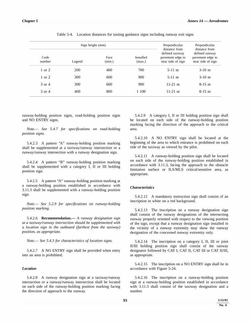
Chapter 5 Annex 14 — Aerodromes
93 4/11/99
runway-holding position signs, road-holding position signsand NO ENTRY signs.
Note.— See 5.4.7 for specifications on road-holdingposition signs.
5.4.2.3 A pattern “A” runway-holding position markingshall be supplemented at a taxiway/runway intersection or arunway/runway intersection with a runway designation sign.
5.4.2.4 A pattern “B” runway-holding position markingshall be supplemented with a category I, II or III holdingposition sign.
5.4.2.5 A pattern “A” runway-holding position marking ata runway-holding position established in accordance with3.11.3 shall be supplemented with a runway-holding positionsign.
Note.— See 5.2.9 for specifications on runway-holdingposition marking.
5.4.2.6 Recommendation.— A runway designation signat a taxiway/runway intersection should be supplemented witha location sign in the outboard (farthest from the taxiway)position, as appropriate.
Note.— See 5.4.3 for characteristics of location signs.
5.4.2.7 A NO ENTRY sign shall be provided when entryinto an area is prohibited.
Location
5.4.2.8 A runway designation sign at a taxiway/runwayintersection or a runway/runway intersection shall be locatedon each side of the runway-holding position marking facingthe direction of approach to the runway.
5.4.2.9 A category I, II or III holding position sign shallbe located on each side of the runway-holding positionmarking facing the direction of the approach to the criticalarea.
5.4.2.10 A NO ENTRY sign shall be located at thebeginning of the area to which entrance is prohibited on eachside of the taxiway as viewed by the pilot.
5.4.2.11 A runway-holding position sign shall be locatedon each side of the runway-holding position established inaccordance with 3.11.3, facing the approach to the obstaclelimitation surface or ILS/MLS critical/sensitive area, asappropriate.
Characteristics
5.4.2.12 A mandatory instruction sign shall consist of aninscription in white on a red background.
5.4.2.13 The inscription on a runway designation signshall consist of the runway designations of the intersectingrunway properly oriented with respect to the viewing positionof the sign, except that a runway designation sign installed inthe vicinity of a runway extremity may show the runwaydesignation of the concerned runway extremity only.
5.4.2.14 The inscription on a category I, II, III or jointII/III holding position sign shall consist of the runwaydesignator followed by CAT I, CAT II, CAT III or CAT II/III,as appropriate.
5.4.2.15 The inscription on a NO ENTRY sign shall be inaccordance with Figure 5-24.
5.4.2.16 The inscription on a runway-holding positionsign at a runway-holding position established in accordancewith 3.11.3 shall consist of the taxiway designation and anumber.
Table 5-4. Location distances for taxiing guidance signs including runway exit signs
Sign height (mm) Perpendiculardistance from
defined taxiwaypavement edge tonear side of sign
Perpendiculardistance from
defined runwaypavement edge tonear side of sign
Codenumber Legend
Face(min.)
Installed(max.)
1 or 2 200 400 700 5-11 m 3-10 m
1 or 2 300 600 900 5-11 m 3-10 m
3 or 4 300 600 900 11-21 m 8-15 m
3 or 4 400 800 1 100 11-21 m 8-15 m
1/11/01
No. 4

Annex 14 — Aerodromes Volume I
5.4.2.17 Where appropriate, the following inscriptions/symbol shall be used:
Inscription/ Usesymbol
Runway To indicate a runway-holding designation of position at a runway extremitya runwayextremity
OR
Runway To indicate a runway-holding designation of position located at otherboth extremities taxiway/runway intersections orof a runway runway/runway intersections
25 CAT I To indicate a category I runway-(Example) holding position at the threshold
of runway 25
25 CAT II To indicate a category II runway-(Example) holding position at the threshold
of runway 25
25 CAT III To indicate a category III runway-(Example) holding position at the threshold
of runway 25
25 CAT II/III To indicate a joint(Example) category II/III runway-holding
position at the threshold of runway 25
NO ENTRY To indicate that entry to an area symbol is prohibited
B2 To indicate a runway-holding(Example) position established in accordance
with 3.11.3
5.4.3 Information signs
Note.— See Figure 5-25 for pictorial representations ofinformation signs.
Application
5.4.3.1 An information sign shall be provided where thereis an operational need to identify by a sign, a specific location,or routing (direction or destination) information.
5.4.3.2 Information signs shall include: direction signs,location signs, destination signs, runway exit signs, runwayvacated signs and intersection take-off signs.
5.4.3.3 A runway exit sign shall be provided where thereis an operational need to identify a runway exit.
5.4.3.4 A runway vacated sign shall be provided wherethe exit taxiway is not provided with taxiway centre line lightsand there is a need to indicate to a pilot leaving a runway theperimeter of the ILS/MLS critical/sensitive area or the loweredge of the inner transitional surface whichever is farther fromthe runway centre line.
Note.— See 5.3.15 for specifications on colour codingtaxiway centre line lights.
5.4.3.5 Recommendation.— An intersection take-off signshould be provided when there is an operational need toindicate the remaining take-off run available (TORA) forintersection take-offs.
5.4.3.6 Recommendation.— Where necessary, a desti-nation sign should be provided to indicate the direction to aspecific destination on the aerodrome, such as cargo area,general aviation, etc.
5.4.3.7 A combined location and direction sign shall beprovided when it is intended to indicate routing informationprior to a taxiway intersection.
5.4.3.8 A direction sign shall be provided when there isan operational need to identify the designation and direction oftaxiways at an intersection.
5.4.3.9 Recommendation.— A location sign should beprovided at an intermediate holding position.
5.4.3.10 A location sign shall be provided in conjunctionwith a runway designation sign except at a runway/runwayintersection.
5.4.3.11 A location sign shall be provided in conjunctionwith a direction sign, except that it may be omitted where anaeronautical study indicates that it is not needed.
5.4.3.12 Recommendation.— Where necessary, a locationsign should be provided to identify taxiways exiting an apron ortaxiways beyond an intersection.
5.4.3.13 Recommendation.— Where a taxiway ends atan intersection such as a ‘‘T’’ and it is necessary to identifythis, a barricade, direction sign and/or other appropriatevisual aid should be used.
Location
5.4.3.14 Except as specified in 5.4.3.16 and 5.4.3.24information signs shall, wherever practicable, be located on theleft-hand side of the taxiway in accordance with Table 5-4.
5.4.3.15 At a taxiway intersection, information signsshall be located prior to the intersection and in line with the
4/11/99 941/11/01
No. 4

Chapter 5 Annex 14 — Aerodromes
taxiway intersection marking. Where there is no taxiwayintersection marking, the signs shall be installed at least60 m from the centre line of the intersecting taxiway wherethe code number is 3 or 4 and at least 40 m where the codenumber is 1 or 2.
Note.— A location sign installed beyond a taxiwayintersection may be installed on either side of a taxiway.
5.4.3.16 A runway exit sign shall be located on the sameside of the runway as the exit is located (i.e. left or right) andpositioned in accordance with Table 5-4.
5.4.3.17 A runway exit sign shall be located prior to therunway exit point in line with a position at least 60 m prior tothe point of tangency where the code number is 3 or 4, and atleast 30 m where the code number is 1 or 2.
5.4.3.18 A runway vacated sign shall be located at leaston one side of the taxiway. The distance between the sign andthe centre line of a runway shall be not less than the greater ofthe following:
a) the distance between the centre line of the runway andthe perimeter of the ILS/MLS critical/sensitive area; or
b) the distance between the centre line of the runway andthe lower edge of the inner transitional surface.
5.4.3.19 Where provided in conjunction with a runwayvacated sign, the taxiway location sign shall be positionedoutboard of the runway vacated sign.
5.4.3.20 An intersection take-off sign shall be located atthe left-hand side of the entry taxiway. The distance betweenthe sign and the centre line of the runway shall be not less than60 m where the code number is 3 or 4 and not less than 45 mwhere the code number is 1 or 2.
5.4.3.21 A taxiway location sign installed in conjunctionwith a runway designation sign shall be positioned outboard ofthe runway designation sign.
5.4.3.22 Recommendation.— A destination sign shouldnot normally be collocated with a location or direction sign.
5.4.3.23 An information sign other than a location signshall not be collocated with a mandatory instruction sign.
5.4.3.24 Recommendation.— A direction sign, barricadeand/or other appropriate visual aid used to identify a ‘‘T’’intersection should be located on the opposite side of theintersection facing the taxiway.
Characteristics
5.4.3.25 An information sign other than a location signshall consist of an inscription in black on a yellow background.
5.4.3.26 A location sign shall consist of an inscription inyellow on a black background and where it is a stand-alonesign shall have a yellow border.
5.4.3.27 The inscription on a runway exit sign shallconsist of the designator of the exit taxiway and an arrowindicating the direction to follow.
5.4.3.28 The inscription on a runway vacated sign shalldepict the pattern A runway-holding position marking asshown in Figure 5-25.
5.4.3.29 The inscription on an intersection take-off signshall consist of a numerical message indicating the remainingtake-off run available in metres plus an arrow, appropriatelylocated and oriented, indicating the direction of the take-off asshown in Figure 5-25.
5.4.3.30 The inscription on a destination sign shallcomprise an alpha, alphanumerical or numerical messageidentifying the destination plus an arrow indicating thedirection to proceed as shown in Figure 5-25.
5.4.3.31 The inscription on a direction sign shall comprisean alpha or alphanumerical message identifying the taxiway(s)plus an arrow or arrows appropriately oriented as shown inFigure 5-25.
5.4.3.32 The inscription on a location sign shall comprisethe designation of the location taxiway, runway or otherpavement the aircraft is on or is entering and shall not containarrows.
5.4.3.33 Recommendation.— Where it is necessary toidentify each of a series of intermediate holding positions onthe same taxiway, the location sign should consist of thetaxiway designation and a number.
5.4.3.34 Where a location sign and direction signs areused in combination:
a) all direction signs related to left turns shall be placed onthe left side of the location sign and all direction signsrelated to right turns shall be placed on the right side ofthe location sign, except that where the junction consistsof one intersecting taxiway, the location sign mayalternatively be placed on the left hand side;
b) the direction signs shall be placed such that the directionof the arrows departs increasingly from the vertical withincreasing deviation of the corresponding taxiway;
c) an appropriate direction sign shall be placed next to thelocation sign where the direction of the location taxiwaychanges significantly beyond the intersection; and
d) adjacent direction signs shall be delineated by a verticalblack line as shown in Figure 5-25.
95 4/11/991/11/01
No. 4
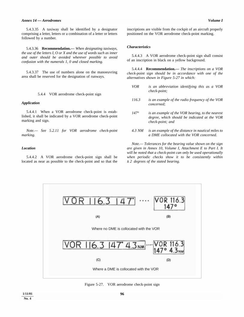
Annex 14 — Aerodromes Volume I
5.4.3.35 A taxiway shall be identified by a designatorcomprising a letter, letters or a combination of a letter or lettersfollowed by a number.
5.4.3.36 Recommendation.— When designating taxiways,the use of the letters I, O or X and the use of words such as innerand outer should be avoided wherever possible to avoidconfusion with the numerals 1, 0 and closed marking.
5.4.3.37 The use of numbers alone on the manoeuvringarea shall be reserved for the designation of runways.
5.4.4 VOR aerodrome check-point sign
Application
5.4.4.1 When a VOR aerodrome check-point is estab-lished, it shall be indicated by a VOR aerodrome check-pointmarking and sign.
Note.— See 5.2.11 for VOR aerodrome check-pointmarking.
Location
5.4.4.2 A VOR aerodrome check-point sign shall belocated as near as possible to the check-point and so that the
inscriptions are visible from the cockpit of an aircraft properlypositioned on the VOR aerodrome check-point marking.
Characteristics
5.4.4.3 A VOR aerodrome check-point sign shall consistof an inscription in black on a yellow background.
5.4.4.4 Recommendation.— The inscriptions on a VORcheck-point sign should be in accordance with one of thealternatives shown in Figure 5-27 in which:
VOR is an abbreviation identifying this as a VORcheck-point;
116.3 is an example of the radio frequency of the VORconcerned;
147° is an example of the VOR bearing, to the nearestdegree, which should be indicated at the VORcheck-point; and
4.3 NM is an example of the distance in nautical miles toa DME collocated with the VOR concerned.
Note.— Tolerances for the bearing value shown on the signare given in Annex 10, Volume I, Attachment E to Part I. Itwill be noted that a check-point can only be used operationallywhen periodic checks show it to be consistently within± 2 degrees of the stated bearing.
4/11/99 96
Figure 5-27. VOR aerodrome check-point sign
Where no DME is collocated with the VOR
Where a DME is collocated with the VOR
1/11/01
No. 4
Chapter 5 Annex 14 — Aerodromes
5.4.5 Aerodrome identification sign
Application
5.4.5.1 Recommendation.— An aerodrome identifi-cation sign should be provided at an aerodrome where thereis insufficient alternative means of visual identification.
Location
5.4.5.2 Recommendation.— The aerodrome identifi-cation sign should be placed on the aerodrome so as to belegible, in so far as is practicable, at all angles above thehorizontal.
Characteristics
5.4.5.3 The aerodrome identification sign shall consist ofthe name of the aerodrome.
5.4.5.4 Recommendation.— The colour selected for thesign should give adequate conspicuity when viewed against itsbackground.
5.4.5.5 Recommendation.— The characters should havea height of not less than 3 m.
5.4.6 Aircraft stand identification signs
Application
5.4.6.1 Recommendation.— An aircraft stand identifi-cation marking should be supplemented with an aircraft standidentification sign where feasible.
Location
5.4.6.2 Recommendation.— An aircraft stand identifi-cation sign should be located so as to be clearly visible fromthe cockpit of an aircraft prior to entering the aircraft stand.
Characteristics
5.4.6.3 Recommendation.— An aircraft stand identifi-cation sign should consist of an inscription in black on ayellow background.
5.4.7 Road-holding position sign
5.4.7.1 A road-holding position sign shall be provided atall road entrances to a runway.
Location
5.4.7.2 The road-holding position sign shall be located1.5 m from one edge of the road (left or right as appropriateto the local traffic regulations) at the holding position.
Characteristics
5.4.7.3 A road-holding position sign shall consist of aninscription in white on a red background.
5.4.7.4 The inscription on a road-holding position signshall be in the national language, be in conformity with thelocal traffic regulations and include the following:
a) a requirement to stop; and
b) where appropriate:
1) a requirement to obtain ATC clearance; and
2) location designator.
Note.— Examples of road-holding position signs are con-tained in the Aerodrome Design Manual, Part 4.
5.4.7.5 A road-holding position sign intended for nightuse shall be retroreflective or illuminated.
5.5 Markers
5.5.1 General
Markers shall be frangible. Those located near a runway ortaxiway shall be sufficiently low to preserve clearance forpropellers and for the engine pods of jet aircraft.
Note 1.— Anchors or chains, to prevent markers whichhave broken from their mounting from blowing away, aresometimes used.
Note 2.— Guidance on frangibility of markers is given inthe Aerodrome Design Manual, Part 6 (in preparation).
5.5.2 Unpaved runway edge markers
Application
5.5.2.1 Recommendation.— Markers should be pro-vided when the extent of an unpaved runway is not clearlyindicated by the appearance of its surface compared with thatof the surrounding ground.
97 4/11/99
Annex 14 — Aerodromes Volume I
Location
5.5.2.2 Recommendation.— Where runway lights areprovided, the markers should be incorporated in the lightfixtures. Where there are no lights, markers of flat rectangularor conical shape should be placed so as to delimit the runwayclearly.
Characteristics
5.5.2.3 Recommendation.— The flat rectangular markersshould have a minimum size of 1 m by 3 m and should be placedwith their long dimension parallel to the runway centre line. Theconical markers should have a height not exceeding 50 cm.
5.5.3 Stopway edge markers
Application
5.5.3.1 Recommendation.— Stopway edge markers shouldbe provided when the extent of a stopway is not clearly indicatedby its appearance compared with that of the surrounding ground.
Characteristics
5.5.3.2 The stopway edge markers shall be sufficientlydifferent from any runway edge markers used to ensure thatthe two types of markers cannot be confused.
Note.— Markers consisting of small vertical boardscamouflaged on the reverse side, as viewed from the runway,have proved operationally acceptable.
5.5.4 Edge markers for snow-covered runways
Application
5.5.4.1 Recommendation.— Edge markers for snow-covered runways should be used to indicate the usable limitsof a snow-covered runway when the limits are not otherwiseindicated.
Note.— Runway lights could be used to indicate the limits.
Location
5.5.4.2 Recommendation.— Edge markers for snow-covered runways should be placed along the sides of therunway at intervals of not more than 100 m, and should belocated symmetrically about the runway centre line at such adistance from the centre line that there is adequate clearancefor wing tips and power plants. Sufficient markers should beplaced across the threshold and end of the runway.
Characteristics
5.5.4.3 Recommendation.— Edge markers for snow-covered runways should consist of conspicuous objects such asevergreen trees about 1.5 m high, or light-weight markers.
5.5.5 Taxiway edge markers
Application
5.5.5.1 Recommendation.— Taxiway edge markers shouldbe provided on a taxiway where the code number is 1 or 2 andtaxiway centre line or edge lights or taxiway centre line markersare not provided.
Location
5.5.5.2 Recommendation.— Taxiway edge markersshould be installed at least at the same locations as would thetaxiway edge lights had they been used.
Characteristics
5.5.5.3 A taxiway edge marker shall be retroreflectiveblue.
5.5.5.4 Recommendation.— The marked surface asviewed by the pilot should be a rectangle and should have aminimum viewing area of 150 cm2.
5.5.5.5 Taxiway edge markers shall be frangible. Theirheight shall be sufficiently low to preserve clearance forpropellers and for the engine pods of jet aircraft.
5.5.6 Taxiway centre line markers
Application
5.5.6.1 Recommendation.— Taxiway centre line markersshould be provided on a taxiway where the code number is 1 or2 and taxiway centre line or edge lights or taxiway edgemarkers are not provided.
5.5.6.2 Recommendation.— Taxiway centre line markersshould be provided on a taxiway where the code number is 3 or4 and taxiway centre line lights are not provided if there is aneed to improve the guidance provided by the taxiway centreline marking.
Location
5.5.6.3 Recommendation.— Taxiway centre line markersshould be installed at least at the same location as wouldtaxiway centre line lights had they been used.
4/11/99 98

STD.ICAO ANNEX /II VOL I-ENGL la997
Chapter 5
Note.- See 5.3. I5. II for the spacing of taxiway centre line lights.
5.5.6.4 Recommendation.- Taxiway centre line markers should normally be located on the taxiway centre line marking except that they may be offset by not more than 30 cm where it is not practicable to locate them on the marking.
Characteristics
5.5.6.5 A taxiway centre line marker shall be retro- reflective green.
5.5.6.6 Recommendation.- The marked surface as viewed by the pilot should be a rectangle and should have a minimum viewing area of 20 cm2.
5.5.6.7 Taxiway centre line markers shall be so designed and fitted as to withstand being run over by the wheels of an aircraft without damage either to the aircraft or to the markers themselves.
5.5.7 Unpaved taxiway edge markers
Applhtion
5.5.7.1 Recommendation.- Where the extent of an unpaved taxiway is not clearly indicated by its appearance compared with that of the surrounding ground, markers should be provided.
Annex I4 - Aerodromes
Location
5.5.7.2 Recommendation.- Where taxiway lights are provided, the markers should be incorporated in the light fixtures. Where there are no lights, markers of conical shape should be placed so as to delimit the taxiway clearly.
5.5.8 Boundary markers
Apphzlion
5.5.8.1 Boundary markers shall be provided at an aero- drome where the landing area has no runway.
Location
5.5.8.2 Boundary markers shall be spaced along the boundary of the landing area at intervals of not more than 200 m, if the type shown in Figure 5-28 is used, or approxi- mately 90 m, if the conical type is used with a marker at any comer.
Characteristics
5.5.8.3 Recommendation.- Boundary markers should be of a form similar to that shown in Figure 5-28, or in the form of a cone not less than 50 cm high and not less than 7.5 cm in diameter at the base. The markers should be coloured to contrast with the background against which they will be seen. A single colour, orange or red, or two contrasting colours, orange and white or alternatively red and white, should be used, except where such colours merge with the background.
Figure 5-28. Boundary markers
99 4/U/99

CHAPTER 6. VISUAL AIDS FOR DENOTING OBSTACLES
6.1 Objects to be markedand/or lighted
Note.— The marking and/or lighting of obstacles isintended to reduce hazards to aircraft by indicating thepresence of the obstacles. It does not necessarily reduceoperating limitations which may be imposed by an obstacle.
6.1.1 Recommendation.— A fixed obstacle that extendsabove a take-off climb surface within 3 000 m of the inner edgeof the take-off climb surface should be marked and, if therunway is used at night, lighted, except that:
a) such marking and lighting may be omitted when theobstacle is shielded by another fixed obstacle;
b) the marking may be omitted when the obstacle is lightedby medium-intensity obstacle lights, Type A, by day andits height above the level of the surrounding ground doesnot exceed 150 m;
c) the marking may be omitted when the obstacle is lightedby high-intensity obstacle lights by day; and
d) the lighting may be omitted where the obstacle is alighthouse and an aeronautical study indicates thelighthouse light to be sufficient.
6.1.2 Recommendation.— A fixed object, other than anobstacle, adjacent to a take-off climb surface should bemarked and, if the runway is used at night, lighted if suchmarking and lighting is considered necessary to ensure itsavoidance, except that the marking may be omitted when:
a) the object is lighted by medium-intensity obstacle lights,Type A, by day and its height above the level of thesurrounding ground does not exceed 150 m; or
b) the object is lighted by high-intensity obstacle lights byday.
6.1.3 A fixed obstacle that extends above an approach ortransitional surface within 3 000 m of the inner edge of theapproach surface shall be marked and, if the runway is used atnight, lighted, except that:
a) such marking and lighting may be omitted when theobstacle is shielded by another fixed obstacle;
b) the marking may be omitted when the obstacle is lightedby medium-intensity obstacle lights, Type A, by day andits height above the level of the surrounding ground doesnot exceed 150 m;
c) the marking may be omitted when the obstacle is lightedby high-intensity obstacle lights by day; and
d) the lighting may be omitted where the obstacle is alighthouse and an aeronautical study indicates thelighthouse light to be sufficient.
6.1.4 Recommendation.— A fixed obstacle above ahorizontal surface should be marked and, if the aerodrome isused at night, lighted except that:
a) such marking and lighting may be omitted when:
1) the obstacle is shielded by another fixed obstacle; or
2) for a circuit extensively obstructed by immovableobjects or terrain, procedures have been establishedto ensure safe vertical clearance below prescribedflight paths; or
3) an aeronautical study shows the obstacle not to be ofoperational significance;
b) the marking may be omitted when the obstacle is lightedby medium-intensity obstacle lights, Type A, by day andits height above the level of the surrounding ground doesnot exceed 150 m;
c) the marking may be omitted when the obstacle is lightedby high-intensity obstacle lights by day; and
d) the lighting may be omitted where the obstacle is alighthouse and an aeronautical study indicates thelighthouse light to be sufficient.
6.1.5 A fixed object that extends above an obstacleprotection surface shall be marked and, if the runway is usedat night, lighted.
Note.— See 5.3.5 for information on the obstacle protectionsurface.
4/11/99 100 ANNEX 14 — VOLUME I
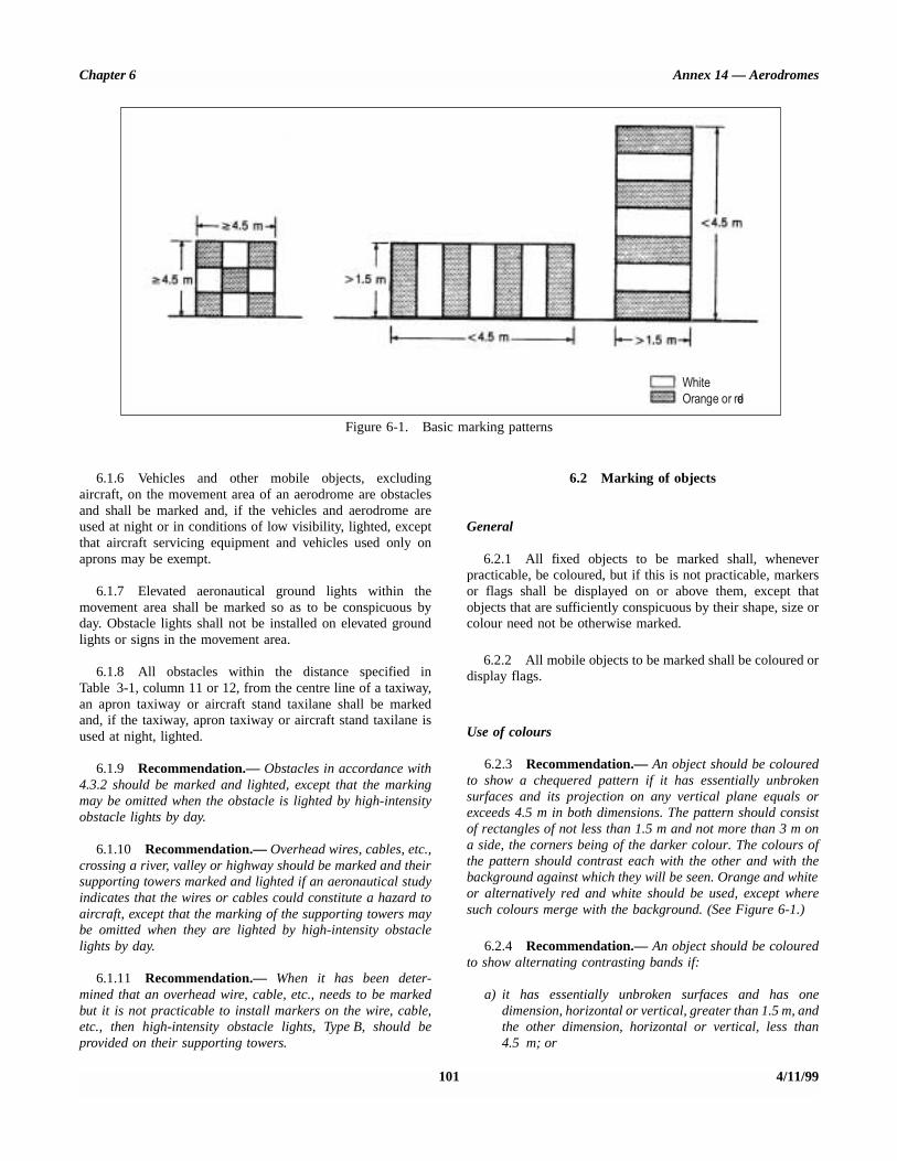
Chapter 6 Annex 14 — Aerodromes
Figure 6-1. Basic marking patterns
WhiteOrange or red
6.1.6 Vehicles and other mobile objects, excludingaircraft, on the movement area of an aerodrome are obstaclesand shall be marked and, if the vehicles and aerodrome areused at night or in conditions of low visibility, lighted, exceptthat aircraft servicing equipment and vehicles used only onaprons may be exempt.
6.1.7 Elevated aeronautical ground lights within themovement area shall be marked so as to be conspicuous byday. Obstacle lights shall not be installed on elevated groundlights or signs in the movement area.
6.1.8 All obstacles within the distance specified inTable 3-1, column 11 or 12, from the centre line of a taxiway,an apron taxiway or aircraft stand taxilane shall be markedand, if the taxiway, apron taxiway or aircraft stand taxilane isused at night, lighted.
6.1.9 Recommendation.— Obstacles in accordance with4.3.2 should be marked and lighted, except that the markingmay be omitted when the obstacle is lighted by high-intensityobstacle lights by day.
6.1.10 Recommendation.— Overhead wires, cables, etc.,crossing a river, valley or highway should be marked and theirsupporting towers marked and lighted if an aeronautical studyindicates that the wires or cables could constitute a hazard toaircraft, except that the marking of the supporting towers maybe omitted when they are lighted by high-intensity obstaclelights by day.
6.1.11 Recommendation.— When it has been deter-mined that an overhead wire, cable, etc., needs to be markedbut it is not practicable to install markers on the wire, cable,etc., then high-intensity obstacle lights, Type B, should beprovided on their supporting towers.
6.2 Marking of objects
General
6.2.1 All fixed objects to be marked shall, wheneverpracticable, be coloured, but if this is not practicable, markersor flags shall be displayed on or above them, except thatobjects that are sufficiently conspicuous by their shape, size orcolour need not be otherwise marked.
6.2.2 All mobile objects to be marked shall be coloured ordisplay flags.
Use of colours
6.2.3 Recommendation.— An object should be colouredto show a chequered pattern if it has essentially unbrokensurfaces and its projection on any vertical plane equals orexceeds 4.5 m in both dimensions. The pattern should consistof rectangles of not less than 1.5 m and not more than 3 m ona side, the corners being of the darker colour. The colours ofthe pattern should contrast each with the other and with thebackground against which they will be seen. Orange and whiteor alternatively red and white should be used, except wheresuch colours merge with the background. (See Figure 6-1.)
6.2.4 Recommendation.— An object should be colouredto show alternating contrasting bands if:
a) it has essentially unbroken surfaces and has onedimension, horizontal or vertical, greater than 1.5 m, andthe other dimension, horizontal or vertical, less than4.5 m; or
101 4/11/99

Annex 14 — Aerodromes Volume I
b) it is of skeletal type with either a vertical or a horizontaldimension greater than 1.5 m.
The bands should be perpendicular to the longest dimensionand have a width approximately 1/7 of the longest dimensionor 30 m, whichever is less. The colours of the bands shouldcontrast with the background against which they will be seen.Orange and white should be used, except where such coloursare not conspicuous when viewed against the background. Thebands on the extremities of the object should be of the darkercolour. (See Figures 6-1 and 6-2.)
Note.— Table 6-1 shows a formula for determining bandwidths and for having an odd number of bands, thuspermitting both the top and bottom bands to be of the darkercolour.
6.2.5 Recommendation.— An object should be colouredin a single conspicuous colour if its projection on any verticalplane has both dimensions less than 1.5 m. Orange or redshould be used, except where such colours merge with thebackground.
Note.— Against some backgrounds it may be found necess-ary to use a different colour from orange or red to obtainsufficient contrast.
6.2.6 Recommendation.— When mobile objects aremarked by colour, a single conspicuous colour, preferably redor yellowish green for emergency vehicles and yellow forservice vehicles should be used.
Table 6-1. Marking band widths
Use of markers
6.2.7 Markers displayed on or adjacent to objects shall belocated in conspicuous positions so as to retain the generaldefinition of the object and shall be recognizable in clearweather from a distance of at least 1 000 m for an object to beviewed from the air and 300 m for an object to be viewed fromthe ground in all directions in which an aircraft is likely to
approach the object. The shape of markers shall be distinctiveto the extent necessary to ensure that they are not mistaken formarkers employed to convey other information, and they shallbe such that the hazard presented by the object they mark isnot increased.
6.2.8 Recommendation.— A marker displayed on anoverhead wire, cable, etc., should be spherical and have adiameter of not less than 60 cm.
6.2.9 Recommendation.— The spacing between twoconsecutive markers or between a marker and a supportingtower should be appropriate to the diameter of the marker, butin no case should the spacing exceed:
a) 30 m where the marker diameter is 60 cm progressivelyincreasing with the diameter of the marker to
b) 35 m where the marker diameter is 80 cm and furtherprogressively increasing to a maximum of
c) 40 m where the marker diameter is of at least 130 cm.
Where multiple wires, cables, etc. are involved, a markershould be located not lower than the level of the highest wireat the point marked.
6.2.10 Recommendation.— A marker should be of onecolour. When installed, white and red, or white and orangemarkers should be displayed alternately. The colour selectedshould contrast with the background against which it will beseen.
Use of flags
6.2.11 Flags used to mark objects shall be displayedaround, on top of, or around the highest edge of, the object.When flags are used to mark extensive objects or groups ofclosely spaced objects, they shall be displayed at least every15 m. Flags shall not increase the hazard presented by theobject they mark.
6.2.12 Flags used to mark fixed objects shall not be lessthan 0.6 m square and flags used to mark mobile objects, notless than 0.9 m square.
6.2.13 Recommendation.— Flags used to mark fixedobjects should be orange in colour or a combination of twotriangular sections, one orange and the other white, or one redand the other white, except that where such colours merge withthe background, other conspicuous colours should be used.
6.2.14 Flags used to mark mobile objects shall consist ofa chequered pattern, each square having sides of not less than0.3 m. The colours of the pattern shall contrast each with theother and with the background against which they will be seen.Orange and white or alternatively red and white shall be used,except where such colours merge with the background.
Longest dimension
Greaterthan
Notexceeding Band width
1.5 m 210 m 1/7 of longest dimension210 m 270 m 1/9 ’’ ’’ ’’270 m 330 m 1/11 ’’ ’’ ’’330 m 390 m 1/13 ’’ ’’ ’’390 m 450 m 1/15 ’’ ’’ ’’450 m 510 m 1/17 ’’ ’’ ’’510 m 570 m 1/19 ’’ ’’ ’’570 m 630 m 1/21 ’’ ’’ ’’
4/11/99 102

STD.ICAO ANNEX 14 VOL I-ENGL L=l=l=l - 'I81ILlllb OLll879b 53b -
Chapter 6 Annex I4 - Aerodromes
:. :::. :. ::: ::::. ~,..~.~.~~.~.~,~ .,: ;.. ;:. ~...~.~,~.~.~.~.~.~i~.~.~
A Roof top pattern A’ Plain roof pattern B Curved surface C Skeleton structure
Note.- H is less the 45 m for the examples shown above. For greater heights intermediate lights musf be added as shown below.
Number of lights = N = 7)
Light spacing = X = 4 5 45 m
Figure 6-2. Examples of marking and lighting of tall structures
103 4/l 1199

Annex 14 — Aerodromes Volume I
6.3 Lighting of objects
Use of obstacle lights
6.3.1 The presence of objects which must be lighted, asspecified in 6.1, shall be indicated by low-, medium- orhigh-intensity obstacle lights, or a combination of such lights.
Note.— High-intensity obstacle lights are intended for dayuse as well as night use. Care is needed to ensure that theselights do not create disconcerting dazzle. Guidance on thedesign, location and operation of high-intensity obstacle lightsis given in the Aerodrome Design Manual, Part 4.
6.3.2 Recommendation.— Low-intensity obstacle lights,Type A or B, should be used where the object is a lessextensive one and its height above the surrounding ground isless than 45 m.
6.3.3 Recommendation.— Where the use of low-intensityobstacle lights, Type A or B, would be inadequate or an earlyspecial warning is required, then medium- or high-intensityobstacle lights should be used.
6.3.4 Low-intensity obstacle lights, Type C, shall bedisplayed on vehicles and other mobile objects excludingaircraft.
6.3.5 Low-intensity obstacle lights, Type D, shall bedisplayed on follow-me vehicles.
6.3.6 Recommendation.— Low-intensity obstacle lights,Type B, should be used either alone or in combination withmedium-intensity obstacle lights, Type B, in accordance with6.3.7.
6.3.7 Recommendation.— Medium-intensity obstaclelights, Type A, B or C, should be used where the object is anextensive one or its height above the level of the surroundingground is greater than 45 m. Medium-intensity obstacle lights,Types A and C, should be used alone, whereas medium-intensity obstacle lights, Type B, should be used either aloneor in combination with low-intensity obstacle lights, Type B.
Note.— A group of trees or buildings is regarded as anextensive object.
6.3.8 Recommendation.— High-intensity obstacle lights,Type A, should be used to indicate the presence of an object ifits height above the level of the surrounding ground exceeds150 m and an aeronautical study indicates such lights to beessential for the recognition of the object by day.
6.3.9 Recommendation.— High-intensity obstacle lights,Type B, should be used to indicate the presence of a towersupporting overhead wires, cables, etc., where:
a) an aeronautical study indicates such lights to beessential for the recognition of the presence of wires,cables, etc.; or
b) it has not been found practicable to install markers onthe wires, cables, etc.
6.3.10 Recommendation.— Where, in the opinion of theappropriate authority, the use of high-intensity obstacle lights,Type A or B, or medium-intensity obstacle lights, Type A, atnight may dazzle pilots in the vicinity of an aerodrome (withinapproximately 10 000 m radius) or cause significantenvironmental concerns, a dual obstacle lighting systemshould be provided. This system should be composed ofhigh-intensity obstacle lights, Type A or B, or medium-intensity obstacle lights, Type A, as appropriate, for daytimeand twilight use and medium-intensity obstacle lights, Type Bor C, for night-time use.
Location of obstacle lights
Note.— Recommendations on how a combination of low-,medium-, and/or high-intensity lights on obstacles should bedisplayed are given in Appendix 6.
6.3.11 One or more low-, medium- or high-intensityobstacle lights shall be located as close as practicable to thetop of the object. The top lights shall be so arranged as to atleast indicate the points or edges of the object highest inrelation to the obstacle limitation surface.
6.3.12 Recommendation.— In the case of chimney orother structure of like function, the top lights should be placedsufficiently below the top so as to minimize contamination bysmoke etc. (see Figures 6-2 and 6-3).
6.3.13 In the case of a tower or antenna structureindicated by high-intensity obstacle lights by day with anappurtenance, such as a rod or an antenna, greater than 12 mwhere it is not practicable to locate a high-intensity obstaclelight on the top of the appurtenance, such a light shall belocated at the highest practicable point and, if practicable, amedium-intensity obstacle light, Type A, mounted on the top.
6.3.14 In the case of an extensive object or of a group ofclosely spaced objects, top lights shall be displayed at least onthe points or edges of the objects highest in relation to theobstacle limitation surface, so as to indicate the generaldefinition and the extent of the objects. If two or more edgesare of the same height, the edge nearest the landing area shallbe marked. Where low-intensity lights are used, they shall bespaced at longitudinal intervals not exceeding 45 m. Wheremedium-intensity lights are used, they shall be spaced atlongitudinal intervals not exceeding 900 m.
6.3.15 Recommendation.— When the obstacle limitationsurface concerned is sloping and the highest point above the
4/11/99 104

Chapter 6 Annex 14 — Aerodromes
obstacle limitation surface is not the highest point of theobject, additional obstacle lights should be placed on thehighest point of the object.
6.3.16 Where an object is indicated by medium-intensityobstacle lights, Type A, and the top of the object is more than105 m above the level of the surrounding ground or theelevation of tops of nearby buildings (when the object to bemarked is surrounded by buildings), additional lights shall beprovided at intermediate levels. These additional intermediatelights shall be spaced as equally as practicable, between thetop lights and ground level or the level of tops of nearbybuildings, as appropriate, with the spacing not exceeding105 m (see 6.3.7).
6.3.17 Where an object is indicated by medium-intensityobstacle lights, Type B, and the top of the object is more than45 m above the level of the surrounding ground or theelevation of tops of nearby buildings (when the object to bemarked is surrounded by buildings), additional lights shall beprovided at intermediate levels. These additional intermediatelights shall be alternately low-intensity obstacle lights, Type B,and medium-intensity obstacle lights, Type B, and shall bespaced as equally as practicable between the top lights andground level or the level of tops of nearby buildings, asappropriate, with the spacing not exceeding 52 m.
6.3.18 Where an object is indicated by medium-intensityobstacle lights, Type C, and the top of the object is more than45 m above the level of the surrounding ground or theelevation of tops of nearby buildings (when the object to bemarked is surrounded by buildings), additional lights shall beprovided at intermediate levels. These additional intermediate
lights shall be spaced as equally as practicable, between thetop lights and ground level or the level of tops of nearbybuildings, as appropriate, with the spacing not exceeding 52 m.
6.3.19 Where high-intensity obstacle lights, Type A, areused, they shall be spaced at uniform intervals not exceeding105 m between the ground level and the top light(s) specifiedin 6.3.11 except that where an object to be marked issurrounded by buildings, the elevation of the tops of thebuildings may be used as the equivalent of the ground levelwhen determining the number of light levels.
6.3.20 Where high-intensity obstacle lights, Type B, areused, they shall be located at three levels:
— at the top of the tower;— at the lowest level of the catenary of the wires or cables;
and— at approximately midway between these two levels.
Note.— In some cases, this may require locating the lightsoff the tower.
6.3.21 Recommendation.— The installation setting anglesfor high-intensity obstacle lights, Types A and B, should be inaccordance with Table 6-2.
6.3.22 The number and arrangement of low-, medium- orhigh-intensity obstacle lights at each level to be marked shallbe such that the object is indicated from every angle inazimuth. Where a light is shielded in any direction by anotherpart of the object, or by an adjacent object, additional lightsshall be provided on that object in such a way as to retain the
105 4/11/99Figure 6-3. Lighting of buildings
AE
A
B
C
D
A, B = 45m - 90mC, D , E , <45 m

Annex 14 — Aerodromes Volume I
general definition of the object to be lighted. If the shieldedlight does not contribute to the definition of the object to belighted, it may be omitted.
Table 6-2. Installation setting angles forhigh-intensity obstacle lights
Low-intensity obstacle light — Characteristics
6.3.23 Low-intensity obstacle lights on fixed objects,Types A and B, shall be fixed-red lights.
6.3.24 Low-intensity obstacle lights, Types A and B, shallbe in accordance with the specifications in Table 6-3.
6.3.25 Low-intensity obstacle lights, Type C, displayed onvehicles associated with emergency or security shall beflashing-blue and those displayed on other vehicles shall beflashing-yellow.
6.3.26 Low-intensity obstacle lights, Type D, displayedon follow-me vehicles shall be flashing-yellow.
6.3.27 Low-intensity obstacle lights, Types C and D, shallbe in accordance with the specifications in Table 6-3.
6.3.28 Low-intensity obstacle lights on objects withlimited mobility such as aerobridges shall be fixed-red. Theintensity of the lights shall be sufficient to ensure conspicuityconsidering the intensity of the adjacent lights and the generallevels of illumination against which they would normally beviewed.
Note.— See Annex 2 for lights to be displayed by aircraft.
6.3.29 Low-intensity obstacle lights on objects withlimited mobility shall as a minimum be in accordance with thespecifications for low-intensity obstacle lights, Type A, inTable 6-3.
Medium-intensity obstacle light — Characteristics
6.3.30 Medium-intensity obstacle lights, Type A, shall beflashing-white lights, Type B shall be flashing-red lights andType C shall be fixed-red lights.
6.3.31 Medium-intensity obstacle lights, Types A, B andC, shall be in accordance with the specifications in Table 6-3.
6.3.32 Medium-intensity obstacle lights, Types A and B,located on an object shall flash simultaneously.
High-intensity obstacle light — Characteristics
6.3.33 High-intensity obstacle lights, Types A and B,shall be flashing-white lights.
6.3.34 High-intensity obstacle lights, Types A and B,shall be in accordance with the specifications in Table 6-3.
6.3.35 High-intensity obstacle lights, Type A, located onan object shall flash simultaneously.
6.3.36 Recommendation.— High-intensity obstaclelights, Type B, indicating the presence of a tower supportingoverhead wires, cables, etc., should flash sequentially; first themiddle light, second the top light and last, the bottom light.The intervals between flashes of the lights should approximatethe following ratios:
Flash interval between Ratio of cycle time
middle and top light 1/13top and bottom light 2/13bottom and middle light 10/13.
Height of light unitabove terrain
Angle of the peakof the beam above
the horizontal
greater than 151 m AGL 0°
122 m to 151 m AGL 1°
92 m to 122 m AGL 2°
less than 92 m AGL 3°
4/11/99 106
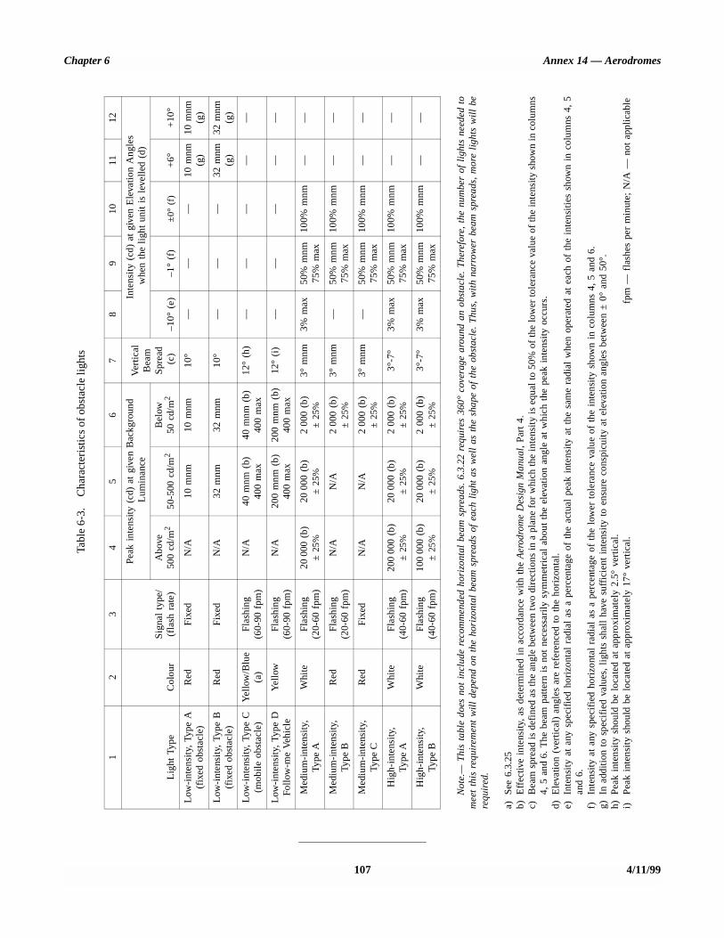
Chapter 6 Annex 14 — Aerodromes
107 4/11/99
Tabl
e 6-
3.C
hara
cter
istic
s of
obs
tacl
e lig
hts
12
34
56
78
910
1112
Lig
ht T
ype
Col
our
Sig
nal
type
/(f
lash
rat
e)
Peak
int
ensi
ty (
cd)
at g
iven
Bac
kgro
und
Lum
inan
ceV
ertic
al
Bea
m
Spre
ad (
c)
Inte
nsit
y (c
d) a
t gi
ven
Ele
vatio
n A
ngle
s w
hen
the
ligh
t un
it i
s le
velle
d (d
)
Abo
ve50
0 cd
/m2
50-5
00 c
d/m
2B
elow
50 c
d/m
2–1
0° (
e)–1
° (f
)±
0° (
f)+
6°+
10°
Low
-int
ensi
ty,
Type
A
(fix
ed o
bsta
cle)
Red
Fix
edN
/A10
mnm
10 m
nm10
°—
——
10 m
nm(g
)10
mnm
(g)
Low
-int
ensi
ty,
Type
B
(fix
ed o
bsta
cle)
Red
Fix
edN
/A32
mnm
32 m
nm10
°—
——
32 m
nm(g
)32
mnm
(g)
Low
-int
ensi
ty,
Type
C
(mob
ile
obst
acle
)Y
ello
w/B
lue
(a)
Fla
shin
g(6
0-90
fpm
)N
/A40
mnm
(b)
400
max
40 m
nm (
b)40
0 m
ax12
° (h
)—
——
——
Low
-int
ensi
ty,
Type
D
Follo
w-m
e V
ehic
leY
ello
wF
lash
ing
(60-
90 f
pm)
N/A
200
mnm
(b)
400
max
200
mnm
(b)
400
max
12°
(i)
——
——
—
Med
ium
-int
ensi
ty,
Type
AW
hite
Fla
shin
g(2
0-60
fpm
)20
000
(b)
± 2
5%20
000
(b)
± 2
5%2
000
(b)
± 2
5%3°
mnm
3% m
ax50
% m
nm75
% m
ax10
0% m
nm—
—
Med
ium
-int
ensi
ty,
Type
BR
edF
lash
ing
(20-
60 f
pm)
N/A
N/A
200
0 (b
)±
25%
3° m
nm—
50%
mnm
75%
max
100%
mnm
——
Med
ium
-int
ensi
ty,
Type
CR
edF
ixed
N/A
N/A
200
0 (b
)±
25%
3° m
nm—
50%
mnm
75%
max
100%
mnm
——
Hig
h-in
tens
ity,
Type
AW
hite
Fla
shin
g(4
0-60
fpm
)20
000
0 (b
)±
25%
2000
0 (b
)±
25%
200
0 (b
)±
25%
3°-7
°3%
max
50%
mnm
75%
max
100%
mnm
——
Hig
h-in
tens
ity,
Type
BW
hite
Fla
shin
g(4
0-60
fpm
)10
000
0 (b
)±
25%
2000
0 (b
)±
25%
2 00
0 (b
)±
25%
3°-7
°3%
max
50%
mnm
75%
max
100%
mnm
——
Not
e.—
Thi
s ta
ble
does
not
inc
lude
rec
omm
ende
d ho
rizo
ntal
bea
m s
prea
ds.
6.3.
22 r
equi
res
360°
cov
erag
e ar
ound
an
obst
acle
. T
here
fore
, th
e nu
mbe
r of
lig
hts
need
ed t
om
eet
this
req
uire
men
t w
ill
depe
nd o
n th
e ho
rizo
ntal
bea
m s
prea
ds o
f ea
ch l
ight
as
wel
l as
the
sha
pe o
f th
e ob
stac
le.
Thu
s, w
ith
narr
ower
bea
m s
prea
ds,
mor
e li
ghts
wil
l be
requ
ired
.
a)S
ee 6
.3.2
5b)
Eff
ectiv
e in
tens
ity,
as d
eter
min
ed i
n ac
cord
ance
with
the
Aer
odro
me
Des
ign
Man
ual,
Part
4.
c)B
eam
spr
ead
is d
efin
ed a
s th
e an
gle
betw
een
two
dire
ctio
ns in
a p
lane
for
whi
ch th
e in
tens
ity is
equ
al to
50%
of
the
low
er to
lera
nce
valu
e of
the
inte
nsity
sho
wn
in c
olum
ns4,
5 a
nd6.
The
bea
m p
atte
rn i
s no
t ne
cess
arily
sym
met
rica
l ab
out
the
elev
atio
n an
gle
at w
hich
the
pea
k in
tens
ity o
ccur
s.d)
Ele
vatio
n (v
ertic
al)
angl
es a
re r
efer
ence
d to
the
hor
izon
tal.
e)In
tens
ity
at a
ny s
peci
fied
hor
izon
tal
radi
al a
s a
perc
enta
ge o
f th
e ac
tual
pea
k in
tens
ity a
t th
e sa
me
radi
al w
hen
oper
ated
at
each
of
the
inte
nsit
ies
show
n in
col
umns
4,
5an
d 6.
f)In
tens
ity
at a
ny s
peci
fied
hor
izon
tal
radi
al a
s a
perc
enta
ge o
f th
e lo
wer
tol
eran
ce v
alue
of
the
inte
nsit
y sh
own
in c
olum
ns 4
, 5
and
6.g)
In a
dditi
on t
o sp
ecif
ied
valu
es,
ligh
ts s
hall
hav
e su
ffic
ient
int
ensi
ty t
o en
sure
con
spic
uity
at
elev
atio
n an
gles
bet
wee
n ±
0°
and
50°.
h)P
eak
inte
nsit
y sh
ould
be
loca
ted
at a
ppro
xim
atel
y 2.
5° v
ertic
al.
i)P
eak
inte
nsit
y sh
ould
be
loca
ted
at a
ppro
xim
atel
y 17
° ve
rtic
al.
fpm
— f
lash
es p
er m
inut
e; N
/A —
not
app
licab
le

CHAPTER 7. VISUAL AIDS FOR DENOTINGRESTRICTED USE AREAS
7.1 Closed runways and taxiways, or parts thereof
Application
7.1.1 A closed marking shall be displayed on a runway ortaxiway, or portion thereof, which is permanently closed to theuse of all aircraft.
7.1.2 Recommendation.— A closed marking should bedisplayed on a temporarily closed runway or taxiway orportion thereof, except that such marking may be omitted whenthe closing is of short duration and adequate warning by airtraffic services is provided.
Location
7.1.3 On a runway a closed marking shall be placed ateach end of the runway, or portion thereof, declared closed,and additional markings shall be so placed that the maximuminterval between markings does not exceed 300 m. On ataxiway a closed marking shall be placed at least at each endof the taxiway or portion thereof closed.
Characteristics
7.1.4 The closed marking shall be of the form and pro-portions as detailed in Figure 7-1, Illustration a), when displayedon a runway, and shall be of the form and proportions asdetailed in Figure 7-1, Illustration b), when displayed on ataxiway. The marking shall be white when displayed on arunway and shall be yellow when displayed on a taxiway.
Note.— When an area is temporarily closed, frangiblebarriers or markings utilizing materials other than paint orother suitable means may be used to identify the closed area.
7.1.5 When a runway or taxiway or portion thereof ispermanently closed, all normal runway and taxiway markingsshall be obliterated.
7.1.6 Lighting on a closed runway or taxiway or portionthereof shall not be operated, except as required for mainten-ance purposes.
7.1.7 In addition to closed markings, when the runway ortaxiway or portion thereof closed is intercepted by a usablerunway or taxiway which is used at night, unserviceabilitylights shall be placed across the entrance to the closed area atintervals not exceeding 3 m (see 7.4.4).
7.2 Non-load-bearing surfaces
Application
7.2.1 Shoulders for taxiways, holding bays and apronsand other non-load-bearing surfaces which cannot readily bedistinguished from load-bearing surfaces and which, if used byaircraft, might result in damage to the aircraft shall have theboundary between such areas and the load-bearing surfacemarked by a taxi side stripe marking.
Note.— The marking of runway sides is specified in 5.2.7.
Location
7.2.2 Recommendation.— A taxi side stripe markingshould be placed along the edge of the load-bearing pavement,with the outer edge of the marking approximately on the edgeof the load-bearing pavement.
Characteristics
7.2.3 Recommendation.— A taxi side stripe markingshould consist of a pair of solid lines, each 15 cm wide andspaced 15 cm apart and the same colour as the taxiway centreline marking.
Note.— Guidance on providing additional transversestripes at an intersection or a small area on the apron is givenin the Aerodrome Design Manual, Part 4.
7.3 Pre-threshold area
Application
7.3.1 Recommendation.— When the surface before athreshold is paved and exceeds 60 m in length and is notsuitable for normal use by aircraft, the entire length before thethreshold should be marked with a chevron marking.
Location
7.3.2 Recommendation.— A chevron marking shouldpoint in the direction of the runway and be placed as shownin Figure 7-2.
ANNEX 14 — VOLUME I 108 4/11/99

STD.ICAO ANNEX l,II VOL I-ENGL I,999 - ‘484L4Lb OLll=lUll2 1(38 D
Chapter 7 Annex 14 - Aerodromes
I - 14.5 m -
1.8
Runway centre line
Illustration a) Closed runway marking
h- Taxiway centre line
Illustration b) Closed taxiway marking
Figure 7-l. Closed runway and taxiway markings
c ,f E3
THRESHOLD t PRE-THRESHOLD AREA .
C f
--- RUNWAY CENTRE LINE
t _I 15m _ 7.5 m I 7.5 m
maX 3Om I _ 30m _ _ 3Om cJ 3Om _ _ 3Om
- Figure 7-2. Pre-threshold marking
109 4/l 1199

Annex 14 — Aerodromes Volume I
Characteristics
7.3.3 Recommendation.— A chevron marking should beof conspicuous colour and contrast with the colour used forthe runway markings; it should preferably be yellow. It shouldhave an over-all width of at least 0.9 m.
7.4 Unserviceable areas
Application
7.4.1 Unserviceability markers shall be displayed wher-ever any portion of a taxiway, apron or holding bay is unfit forthe movement of aircraft but it is still possible for aircraft tobypass the area safely. On a movement area used at night,unserviceability lights shall be used.
Note.— Unserviceability markers and lights are used forsuch purposes as warning pilots of a hole in a taxiway orapron pavement or outlining a portion of pavement, such as onan apron, that is under repair. They are not suitable for usewhen a portion of a runway becomes unserviceable, nor on ataxiway when a major portion of the width becomes unservice-able. In such instances, the runway or taxiway is normallyclosed.
Location
7.4.2 Unserviceability markers and lights shall beplaced at intervals sufficiently close so as to delineate theunserviceable area.
Note.— Guidance on the location of unserviceability lightsis given in Attachment A, Section 13.
Characteristics of unserviceability markers
7.4.3 Unserviceability markers shall consist of conspicu-ous upstanding devices such as flags, cones or marker boards.
Characteristics of unserviceability lights
7.4.4 An unserviceability light shall consist of a red fixedlight. The light shall have an intensity sufficient to ensureconspicuity considering the intensity of the adjacent lights andthe general level of illumination against which it wouldnormally be viewed. In no case shall the intensity be less than10 cd of red light.
Characteristics of unserviceability cones
7.4.5 Recommendation.— An unserviceability coneshould be at least 0.5 m in height and red, orange or yellowor any one of these colours in combination with white.
Characteristics of unserviceability flags
7.4.6 Recommendation.— An unserviceability flagshould be at least 0.5 m square and red, orange or yellow orany one of these colours in combination with white.
Characteristics of unserviceability marker boards
7.4.7 Recommendation.— An unserviceability markerboard should be at least 0.5 m in height and 0.9 m in length,with alternate red and white or orange and white verticalstripes.
4/11/99 110
CHAPTER 8. EQUIPMENT AND INSTALLATIONS
8.1 Secondary power supply
General
Application
8.1.1 Recommendation.— A secondary power supplyshould be provided, capable of supplying the power require-ments of at least the aerodrome facilities listed below:
a) the signalling lamp and the minimum lighting necessaryto enable air traffic services personnel to carry out theirduties;
Note.— The requirement for minimum lighting maybe met by other than electrical means.
b) all obstacle lights which, in the opinion of the appro-priate authority, are essential to ensure the safe oper-ation of aircraft;
c) approach, runway and taxiway lighting as specified in8.1.6 to 8.1.9;
d) meteorological equipment;
e) essential security lighting, if provided in accordance with8.5;
f) essential equipment and facilities for the aerodromeresponding emergency agencies; and
g) floodlighting on a designated isolated aircraft parkingposition if provided in accordance with 5.3.21.1.
Note.— Specifications for secondary power supply forradio navigation aids and ground elements of communicationssystems are given in Annex 10, Volume I, Part I, Chapter 2.
Characteristics
8.1.2 Recommendation.— Electric power supplyconnections to those facilities for which secondary power isrequired should be so arranged that the facilities areautomatically connected to the secondary power supply onfailure of the normal source of power.
8.1.3 Recommendation.— The time interval betweenfailure of the normal source of power and the complete
restoration of the services required by 8.1.1 should be as shortas practicable and should not exceed two minutes, except thatfor visual aids associated with non-precision, precisionapproach or take-off runways the requirements of Table 8-1 formaximum switch-over times should apply.
Note 1.— In certain cases, less than thirty seconds has beenfound to be attainable.
Note 2.— A definition of switch-over time is given inChapter 1.
8.1.4 The provision of a definition of switch-over timeshall not require the replacement of an existing secondarypower supply before 1 January 2010. However, for a secondarypower supply installed after 4 November 1999, the electricpower supply connections to those facilities for whichsecondary power is required shall be so arranged that thefacilities are capable of meeting the requirements of Table 8-1for maximum switch-over times as defined in Chapter 1.
8.1.5 Recommendation.— Requirements for a secondarypower supply should be met by either of the following:
— independent public power, which is a source of powersupplying the aerodrome service from a substation otherthan the normal substation through a transmission linefollowing a route different from the normal power supplyroute and such that the possibility of a simultaneousfailure of the normal and independent public powersupplies is extremely remote; or
— standby power unit(s), which are engine generators,batteries, etc., from which electric power can beobtained.
Note.— Guidance on secondary power supply is given inthe Aerodrome Design Manual, Part 5.
Visual aids
Application
8.1.6 Recommendation.— At an aerodrome where theprimary runway is a non-instrument runway, a secondarypower supply capable of meeting the requirements of 8.1.3should be provided, except that a secondary power supply forvisual aids need not be provided when an emergency lightingsystem in accordance with the specification of 5.3.2 isprovided and capable of being deployed in 15 minutes.
ANNEX 14 — VOLUME I 111 4/11/99

Annex 14 — Aerodromes Volume I
4/11/99 112
Table 8-1. Secondary power supply requirements(see 8.1.3)
Runway Lighting aids requiring powerMaximum switch-over time
Non-instrument Visual approach slope indicatorsa
Runway edgeb
Runway thresholdb
Runway endb
Obstaclea
See8.1.3 and
8.1.6
Non-precision approach Approach lighting systemVisual approach slope indicatorsa, d
Runway edged
Runway thresholdd
Runway endObstaclea
15 seconds15 seconds15 seconds15 seconds15 seconds15 seconds
Precision approach category I Approach lighting systemRunway edged
Visual approach slope indicatorsa, d
Runway thresholdd
Runway endEssential taxiwaya
Obstaclea
15 seconds15 seconds15 seconds15 seconds15 seconds15 seconds15 seconds
Precision approach category II/III Approach lighting systemSupplementary approach lighting barrettesObstaclea
Runway edgeRunway thresholdRunway endRunway centre lineRunway touchdown zoneAll stop barsEssential taxiway
15 seconds 1 second
15 seconds15 seconds 1 second 1 second 1 second 1 second 1 second
15 seconds
Runway meant for take-off in runway visual range conditions less than a value of 800 m.
Runway edgeRunway endRunway centre lineAll stop barsEssential taxiwaya
Obstaclea
15 secondsc
1 second1 second1 second
15 seconds15 seconds
a. Supplied with secondary power when their operation is essential to the safety of flight operation.b. See Chapter 5, 5.3.2 regarding the use of emergency lighting.c. One second where no runway centre line lights are provided.d. One second where approaches are over hazardous or precipitous terrain.
Chapter 8 Annex 14 — Aerodromes
Note.— Guidance on means of achieving the specifiedsecondary power supply switch-over times, etc., is given in theAerodrome Design Manual, Part 5.
8.1.7 Recommendation.— At an aerodrome where theprimary runway is a non-precision approach runway, asecondary power supply capable of meeting the requirementsof Table 8-1 should be provided except that a secondary powersupply for visual aids need not be provided for more than onenon-precision approach runway.
8.1.8 For a precision approach runway, a secondarypower supply capable of meeting the requirements ofTable 8-1 for the appropriate category of precision approachrunway shall be provided. Electric power supply connectionsto those facilities for which secondary power is required shallbe so arranged that the facilities are automatically connected tothe secondary power supply on failure of the normal source ofpower.
8.1.9 For a runway meant for take-off in runway visualrange conditions less than a value of 800 m, a secondarypower supply capable of meeting the relevant requirements ofTable 8-1 shall be provided.
Note.— Guidance on electrical systems is included in theAerodrome Design Manual, Part 5.
8.2 Electrical systems
8.2.1 For a runway meant for use in runway visual rangeconditions less than a value of 550 m, the electrical systemsfor the power supply, lighting and control of the lightingsystems included in Table 8-1 shall be so designed that anequipment failure will not leave the pilot with inadequatevisual guidance or misleading information.
Note.— Guidance on means of providing this protection isgiven in the Aerodrome Design Manual, Part 5.
8.2.2 Where the secondary power supply of an aerodromeis provided by the use of duplicate feeders, such supplies shallbe physically and electrically separate so as to ensure therequired level of availability and independence.
Note.— Guidance on acceptable power source arrange-ments for the use of duplicate feeders for a secondary powersupply is given in the Aerodrome Design Manual, Part 5.
8.2.3 Where a runway forming part of a standard taxi-route is provided with runway lighting and taxiway lighting,the lighting systems shall be interlocked to preclude the possi-bility of simultaneous operation of both forms of lighting.
8.3 Monitoring
Note.— Guidance on this subject is given in the AerodromeDesign Manual, Part 5.
8.3.1 Recommendation.— A system of monitoring visualaids should be employed to ensure lighting system reliability.
8.3.2 Where lighting systems are used for aircraft controlpurposes, such systems shall be monitored automatically so asto provide an immediate indication of any fault which mayaffect the control functions. This information shall be auto-matically relayed to the air traffic service unit.
8.3.3 Recommendation.— For a runway meant for usein runway visual range conditions less than a value of 550 m,the lighting systems detailed in Table 8-1 should be monitoredso as to provide an immediate indication when the service-ability level of any element falls below the minimumserviceability level specified in 9.4.26 to 9.4.30, as appro-priate. This information should be immediately relayed to themaintenance crew.
8.3.4 Recommendation.— For a runway meant for usein runway visual range conditions less than a value of 550 m,the lighting systems detailed in Table 8-1 should be monitoredautomatically to provide an immediate indication when theserviceability level of any element falls below the minimumlevel specified by the appropriate authority below whichoperations should not continue. This information should beautomatically relayed to the air traffic services unit anddisplayed in a prominent position.
Note.— Guidance on air traffic control interface and visualaids monitoring is included in the Aerodrome Design Manual,Part 5.
8.4 Fencing
Application
8.4.1 Recommendation.— A fence or other suitablebarrier should be provided on an aerodrome to prevent theentrance to the movement area of animals large enough to bea hazard to aircraft.
8.4.2 Recommendation.— A fence or other suitablebarrier should be provided on an aerodrome to deter theinadvertent or premeditated access of an unauthorized persononto a non-public area of the aerodrome.
Note 1.— This is intended to include the barring of sewers,ducts, tunnels, etc., where necessary to prevent access.
Note 2.— Special measures may be required to prevent theaccess of an unauthorized person to runways or taxiwayswhich overpass public roads.
113 4/11/991/11/01
No. 4

Annex 14 — Aerodromes Volume I
8.4.3 Recommendation.— Suitable means of protectionshould be provided to deter the inadvertent or premeditatedaccess of unauthorized persons into ground installations andfacilities essential for the safety of civil aviation located off theaerodrome.
Location
8.4.4 Recommendation.— The fence or barrier shouldbe located so as to separate the movement area and otherfacilities or zones on the aerodrome vital to the safe operationof aircraft from areas open to public access.
8.4.5 Recommendation.— When greater security isthought necessary, a cleared area should be provided on bothsides of the fence or barrier to facilitate the work of patrolsand to make trespassing more difficult. Consideration shouldbe given to the provision of a perimeter road inside theaerodrome fencing for the use of both maintenance personneland security patrols.
8.5 Security lighting
Recommendation.— At an aerodrome where it is deemeddesirable for security reasons, a fence or other barrier pro-vided for the protection of international civil aviation and itsfacilities should be illuminated at a minimum essential level.Consideration should be given to locating lights so that theground area on both sides of the fence or barrier, particularlyat access points, is illuminated.
8.6 Airport design
8.6.1 Architectural and infrastructure-related require-ments for the optimum implementation of international civilaviation security measures shall be integrated into the designand construction of new facilities and alterations to existingfacilities at an aerodrome.
Note.— Guidance on all aspects of the planning ofaerodromes including security considerations is contained inthe Airport Planning Manual, Part 1.
8.7 Siting and construction of equipment andinstallations on operational areas
Note 1.— Requirements for obstacle limitation surfaces arespecified in 4.2.
Note 2.— The design of light fixtures and their supportingstructures, light units of visual approach slope indicators,signs, and markers, is specified in 5.3.1, 5.3.5, 5.4.1 and 5.5.1,respectively. Guidance on the frangible design of visual and
non-visual aids for navigation is given in the AerodromeDesign Manual, Part 6 (in preparation).
8.7.1 Unless its function requires it to be there for airnavigation purposes, no equipment or installation shall be:
a) on a runway strip, a runway end safety area, a taxiwaystrip or within the distances specified in Table 3-1,column 11, if it would endanger an aircraft; or
b) on a clearway if it would endanger an aircraft in the air.
8.7.2 Any equipment or installation required for airnavigation purposes which must be located:
a) on that portion of a runway strip within:
1) 75 m of the runway centre line where the codenumber is 3 or 4; or
2) 45 m of the runway centre line where the codenumber is 1 or 2; or
b) on a runway end safety area, a taxiway strip or withinthe distances specified in Table 3-1; or
c) on a clearway and which would endanger an aircraft inthe air;
shall be frangible and mounted as low as possible.
8.7.3 Existing non-visual aids need not meet therequirement of 8.7.2 until 1 January 2010.
8.7.4 Recommendation.— Any equipment or installationrequired for air navigation purposes which must be located onthe non-graded portion of a runway strip should be regardedas an obstacle and should be frangible and mounted as low aspossible.
Note.— Guidance on the siting of navigation aids iscontained in the Aerodrome Design Manual, Part 6 (inpreparation).
8.7.5 Unless its function requires it to be there for airnavigation purposes, no equipment or installation shall belocated within 240 m from the end of the strip and within:
a) 60 m of the extended centre line where the code numberis 3 or 4; or
b) 45 m of the extended centre line where the code numberis 1 or 2;
of a precision approach runway category I, II or III.
8.7.6 Any equipment or installation required for airnavigation purposes which must be located on or near a stripof a precision approach runway category I, II or III and which:
4/11/99 114
Chapter 8 Annex 14 — Aerodromes
a) is situated on that portion of the strip within 77.5 m ofthe runway centre line where the code number is 4 andthe code letter is F; or
b) is situated within 240 m from the end of the strip andwithin:
1) 60 m of the extended runway centre line where thecode number is 3 or 4; or
2) 45 m of the extended runway centre line where thecode number is 1 or 2; or
c) penetrates the inner approach surface, the innertransitional surface or the balked landing surface;
shall be frangible and mounted as low as possible.
8.7.7 Existing non-visual aids need not meet therequirement of 8.7.6 b) until 1 January 2010.
Note.— See 5.3.1.4 for the protection date for existingelevated approach lights.
8.7.8 Recommendation.— Any equipment or installationrequired for air navigation purposes which is an obstacle ofoperational significance in accordance with 4.2.4, 4.2.11,4.2.20 or 4.2.27 should be frangible and mounted as low aspossible.
8.8 Aerodrome vehicle operations
Note 1.— Guidance on aerodrome vehicle operations iscontained in Attachment A, Section 17 and on traffic rules andregulations for vehicles is contained in the Manual of SurfaceMovement Guidance and Control Systems (SMGCS).
Note 2.— It is intended that roads located on the movementarea be restricted to the exclusive use of aerodrome personneland other authorized persons, and that access to the publicbuildings by an unauthorized person will not require use ofsuch roads.
8.8.1 A vehicle shall be operated:
a) on a manoeuvring area only as authorized by the aero-drome control tower; and
b) on an apron only as authorized by the appropriatedesignated authority.
8.8.2 The driver of a vehicle on the movement area shallcomply with all mandatory instructions conveyed by markingsand signs unless otherwise authorized by:
a) the aerodrome control tower when on the manoeuvringarea; or
b) the appropriate designated authority when on the apron.
8.8.3 The driver of a vehicle on the movement area shallcomply with all mandatory instructions conveyed by lights.
8.8.4 The driver of a vehicle on the movement area shallbe appropriately trained for the tasks to be performed and shallcomply with the instructions issued by:
a) the aerodrome control tower, when on the manoeuvringarea; and
b) the appropriate designated authority, when on the apron.
8.8.5 The driver of a radio-equipped vehicle shall estab-lish satisfactory two-way radio communication with the aero-drome control tower before entering the manoeuvring area andwith the appropriate designated authority before entering theapron. The driver shall maintain a continuous listening watchon the assigned frequency when on the movement area.
8.9 Surface movement guidance andcontrol systems
Application
8.9.1 A surface movement guidance and control systemshall be provided at an aerodrome.
Note.— Guidance on surface movement guidance andcontrol systems is contained in the Manual of SurfaceMovement Guidance and Control Systems (SMGCS).
Characteristics
8.9.2 Recommendation.— The design of a surface move-ment guidance and control system should take into account:
a) the density of air traffic;
b) the visibility conditions under which operations areintended;
c) the need for pilot orientation;
d) the complexity of the aerodrome layout; and
e) movements of vehicles.
8.9.3 Recommendation.— The visual aid components ofa surface movement guidance and control system, i.e.markings, lights and signs should be designed to conform withthe relevant specifications in 5.2, 5.3 and 5.4, respectively.
115 4/11/99

Annex 14 — Aerodromes Volume I
8.9.4 Recommendation.— A surface movement guid-ance and control system should be designed to assist in theprevention of inadvertent incursions of aircraft and vehiclesonto an active runway.
8.9.5 Recommendation.— The system should bedesigned to assist in the prevention of collisions betweenaircraft, and between aircraft and vehicles or objects, on anypart of the movement area.
Note.— Guidance on control of stop bars through inductionloops and on a visual taxiing guidance and control system iscontained in the Aerodrome Design Manual, Part 4.
8.9.6 Where a surface movement guidance and controlsystem is provided by selective switching of stop bars andtaxiway centre line lights, the following requirements shall bemet:
a) taxiway routes which are indicated by illuminatedtaxiway centre line lights shall be capable of beingterminated by an illuminated stop bar;
b) the control circuits shall be so arranged that when a stopbar located ahead of an aircraft is illuminated theappropriate section of taxiway centre line lights beyond itis suppressed; and
c) the taxiway centre line lights are activated ahead of anaircraft when the stop bar is suppressed.
Note 1.— See Sections 5.3.15 and 5.3.17 for specificationson taxiway centre line lights and stop bars, respectively.
Note 2.— Guidance on installation of stop bars andtaxiway centre line lights in surface movement guidance andcontrol systems is given in the Aerodrome Design Manual,Part 4.
8.9.7 Recommendation.— Surface movement radar forthe manoeuvring area should be provided at an aerodromeintended for use in runway visual range conditions less than avalue of 350 m.
8.9.8 Recommendation.— Surface movement radar forthe manoeuvring area should be provided at an aerodromeother than that in 8.9.7 when traffic density and operating con-ditions are such that regularity of traffic flow cannot bemaintained by alternative procedures and facilities.
Note.— Guidance on the use of surface movement radar isgiven in the Manual of Surface Movement Guidance andControl Systems (SMGCS) and in the Air Traffic ServicesPlanning Manual (Doc 9426).
4/11/99 116

CHAPTER 9. EMERGENCY AND OTHER SERVICES
9.1 Aerodrome emergency planning
General
Introductory Note.— Aerodrome emergency planning is theprocess of preparing an aerodrome to cope with an emergencyoccurring at the aerodrome or in its vicinity. The objective ofaerodrome emergency planning is to minimize the effects of anemergency, particularly in respect of saving lives and main-taining aircraft operations. The aerodrome emergency plansets forth the procedures for coordinating the response ofdifferent aerodrome agencies (or services) and of thoseagencies in the surrounding community that could be of assist-ance in responding to the emergency. Guidance material toassist the appropriate authority in establishing aerodromeemergency planning is given in the Airport Services Manual,Part 7.
9.1.1 An aerodrome emergency plan shall be establishedat an aerodrome, commensurate with the aircraft operationsand other activities conducted at the aerodrome.
9.1.2 The aerodrome emergency plan shall provide for thecoordination of the actions to be taken in an emergencyoccurring at an aerodrome or in its vicinity.
Note.— Examples of emergencies are: aircraft emerg-encies, sabotage including bomb threats, unlawfully seizedaircraft, dangerous goods occurrences, building fires andnatural disasters.
9.1.3 The plan shall coordinate the response or partici-pation of all existing agencies which, in the opinion of theappropriate authority, could be of assistance in responding toan emergency.
Note.— Examples of agencies are:
— on the aerodrome: air traffic control unit, rescue and firefighting services, aerodrome administration, medical andambulance services, aircraft operators, security services,and police;
— off the aerodrome: fire departments, police, medical andambulance services, hospitals, military, and harbourpatrol or coast guard.
9.1.4 Recommendation.— The plan should provide forcooperation and coordination with the rescue coordinationcentre, as necessary.
9.1.5 Recommendation.— The aerodrome emergencyplan document should include at least the following:
a) types of emergencies planned for;
b) agencies involved in the plan;
c) responsibility and role of each agency, the emergencyoperations centre and the command post, for each typeof emergency;
d) information on names and telephone numbers of officesor people to be contacted in the case of a particularemergency; and
e) a grid map of the aerodrome and its immediate vicinity.
9.1.6 The plan shall observe Human Factors principles toensure optimum response by all existing agencies participatingin emergency operations.
Note.— Guidance material on Human Factors principlescan be found in the Human Factors Training Manual.
Emergency operations centre and command post
9.1.7 Recommendation.— A fixed emergency operationscentre and a mobile command post should be available for useduring an emergency.
9.1.8 Recommendation.— The emergency operationscentre should be a part of the aerodrome facilities and shouldbe responsible for the overall coordination and generaldirection of the response to an emergency.
9.1.9 Recommendation.— The command post should bea facility capable of being moved rapidly to the site of anemergency, when required, and should undertake the localcoordination of those agencies responding to the emergency.
9.1.10 Recommendation.— A person should be assignedto assume control of the emergency operations centre and,when appropriate, another person the command post.
Communication system
9.1.11 Recommendation.— Adequate communicationsystems linking the command post and the emergency oper-ations centre with each other and with the participatingagencies should be provided in accordance with the plan andconsistent with the particular requirements of the aerodrome.
ANNEX 14 — VOLUME I 117 4/11/991/11/01
No. 4
Annex 14 — Aerodromes Volume I
Aerodrome emergency exercise
9.1.12 The plan shall contain procedures for periodictesting of the adequacy of the plan and for reviewing theresults in order to improve its effectiveness.
Note.— The plan includes all participating agencies andassociated equipment.
9.1.13 The plan shall be tested by conducting:
a) a full-scale aerodrome emergency exercise at intervalsnot exceeding two years; and
b) partial emergency exercises in the intervening year toensure that any deficiencies found during the full-scaleaerodrome emergency exercise have been corrected; and
reviewed thereafter, or after an actual emergency, so as tocorrect any deficiency found during such exercises or actualemergency.
Note.— The purpose of a full-scale exercise is to ensure theadequacy of the plan to cope with different types ofemergencies. The purpose of a partial exercise is to ensure theadequacy of the response to individual participating agenciesand components of the plan, such as the communicationssystem.
Emergencies in difficult environments
9.1.14 The plan shall include the ready availability of andcoordination with appropriate specialist rescue services to beable to respond to emergencies where an aerodrome is locatedclose to water and/or swampy areas and where a significantportion of approach or departure operations takes place overthese areas.
9.1.15 Recommendation.— At those aerodromes locatedclose to water and/or swampy areas, or difficult terrain, theaerodrome emergency plan should include the establishment,testing and assessment at regular intervals of a pre-determinedresponse for the specialist rescue services.
9.2 Rescue and fire fighting
General
Introductory Note.— The principal objective of a rescueand fire fighting service is to save lives. For this reason, theprovision of means of dealing with an aircraft accident orincident occurring at, or in the immediate vicinity of, anaerodrome assumes primary importance because it is withinthis area that there are the greatest opportunities of savinglives. This must assume at all times the possibility of, and need
for, extinguishing a fire which may occur either immediatelyfollowing an aircraft accident or incident, or at any timeduring rescue operations.
The most important factors bearing on effective rescue in asurvivable aircraft accident are: the training received, theeffectiveness of the equipment and the speed with whichpersonnel and equipment designated for rescue and firefighting purposes can be put into use.
Requirements to combat building and fuel farm fires, or todeal with foaming of runways, are not taken into account.
Application
9.2.1 Rescue and fire fighting equipment and servicesshall be provided at an aerodrome.
Note.— Public or private organizations, suitably locatedand equipped, may be designated to provide the rescue andfire fighting service. It is intended that the fire station housingthese organizations be normally located on the aerodrome,although an off-aerodrome location is not precluded providedthe response time can be met.
9.2.2 Where an aerodrome is located close towater/swampy areas, or difficult terrain, and where asignificant portion of approach or departure operations takesplace over these areas, specialist rescue services and firefighting equipment appropriate to the hazard and risk shall beavailable.
Note 1.— Special fire fighting equipment need not beprovided for water areas; this does not prevent the provision ofsuch equipment if it would be of practical use, such as whenthe areas concerned include reefs or islands.
Note 2.— The objective is to plan and deploy the necessarylife-saving flotation equipment as expeditiously as possible ina number commensurate with the largest aeroplane normallyusing the aerodrome.
Note 3.— Additional guidance is available in Chapter 13 ofthe Airport Services Manual, Part 1.
Level of protection to be provided
9.2.3 The level of protection provided at an aerodrome forrescue and fire fighting shall be appropriate to the aerodromecategory determined using the principles in 9.2.5 and 9.2.6,except that, where the number of movements of the aeroplanesin the highest category normally using the aerodrome is lessthan 700 in the busiest consecutive three months, the level ofprotection provided shall be not less than one category belowthe determined category.
Note.— Either a take-off or a landing constitutes amovement.
4/11/99 1181/11/01
No. 4
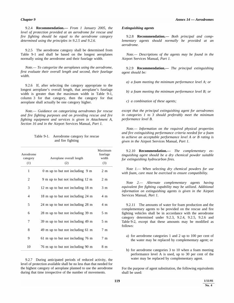
Chapter 9 Annex 14 — Aerodromes
9.2.4 Recommendation.— From 1 January 2005, thelevel of protection provided at an aerodrome for rescue andfire fighting should be equal to the aerodrome categorydetermined using the principles in 9.2.5 and 9.2.6.
9.2.5 The aerodrome category shall be determined fromTable 9-1 and shall be based on the longest aeroplanesnormally using the aerodrome and their fuselage width.
Note.— To categorize the aeroplanes using the aerodrome,first evaluate their overall length and second, their fuselagewidth.
9.2.6 If, after selecting the category appropriate to thelongest aeroplane’s overall length, that aeroplane’s fuselagewidth is greater than the maximum width in Table 9-1,column 3 for that category, then the category for thataeroplane shall actually be one category higher.
Note.— Guidance on categorizing aerodromes for rescueand fire fighting purposes and on providing rescue and firefighting equipment and services is given in Attachment A,Section 16 and in the Airport Services Manual, Part 1.
Table 9-1. Aerodrome category for rescueand fire fighting
9.2.7 During anticipated periods of reduced activity, thelevel of protection available shall be no less than that needed forthe highest category of aeroplane planned to use the aerodromeduring that time irrespective of the number of movements.
Extinguishing agents
9.2.8 Recommendation.— Both principal and comp-lementary agents should normally be provided at anaerodrome.
Note.— Descriptions of the agents may be found in theAirport Services Manual, Part 1.
9.2.9 Recommendation.— The principal extinguishingagent should be:
a) a foam meeting the minimum performance level A; or
b) a foam meeting the minimum performance level B; or
c) a combination of these agents;
except that the principal extinguishing agent for aerodromesin categories 1 to 3 should preferably meet the minimumperformance level B.
Note.— Information on the required physical propertiesand fire extinguishing performance criteria needed for a foamto achieve an acceptable performance level A or B rating isgiven in the Airport Services Manual, Part 1.
9.2.10 Recommendation.— The complementary ex-tinguishing agent should be a dry chemical powder suitablefor extinguishing hydrocarbon fires.
Note 1.— When selecting dry chemical powders for usewith foam, care must be exercised to ensure compatibility.
Note 2.— Alternate complementary agents havingequivalent fire fighting capability may be utilized. Additionalinformation on extinguishing agents is given in the AirportServices Manual, Part 1.
9.2.11 The amounts of water for foam production and thecomplementary agents to be provided on the rescue and firefighting vehicles shall be in accordance with the aerodromecategory determined under 9.2.3, 9.2.4, 9.2.5, 9.2.6 andTable 9-2, except that these amounts may be modified asfollows:
a) for aerodrome categories 1 and 2 up to 100 per cent ofthe water may be replaced by complementary agent; or
b) for aerodrome categories 3 to 10 when a foam meetingperformance level A is used, up to 30 per cent of thewater may be replaced by complementary agent.
For the purpose of agent substitution, the following equivalentsshall be used:
Aerodromecategory Aeroplane overall length
Maximumfuselage
width
(1) (2) (3)
1 0 m up to but not including 9 m 2 m
2 9 m up to but not including 12 m 2 m
3 12 m up to but not including 18 m 3 m
4 18 m up to but not including 24 m 4 m
5 24 m up to but not including 28 m 4 m
6 28 m up to but not including 39 m 5 m
7 39 m up to but not including 49 m 5 m
8 49 m up to but not including 61 m 7 m
9 61 m up to but not including 76 m 7 m
10 76 m up to but not including 90 m 8 m
119 4/11/991/11/01
No. 4

Annex 14 — Aerodromes Volume I
Table 9-2. Minimum usable amounts of extinguishing agents
Foam meeting performance level A Foam meeting performance level B Complementary agents
Aerodromecategory
Water1
(L)
Discharge ratefoam solution/ minute
(L)Water1
(L)
Discharge ratefoam solution/ minute
(L)
Dry2
chemical powders(kg)
(1) (2) (3) (4) (5) (6)
1 350 350 230 230 452 1 000 800 670 550 903 1 800 1 300 1 200 900 1354 3 600 2 600 2 400 1 800 1355 8 100 4 500 5 400 3 000 1806 11 800 6 000 7 900 4 000 2257 18 200 7 900 12 100 5 300 2258 27 300 10 800 18 200 7 200 4509 36 400 13 500 24 300 9 000 450
10 48 200 16 600 32 300 11 200 450
Note 1.— The quantities of water shown in columns 2 and 4 are based on the average overall length of aeroplanes in a given category. Whereoperations of an aeroplane larger than the average size are expected, the quantities of water would need to be recalculated. See the AirportServices Manual, Part 1 for additional guidance.
Note 2.— Any other complementary agent having equivalent fire fighting capability may be used.
Note 1.— The amounts of water specified for foamproduction are predicated on an application rate of8.2 L/min/m2 for a foam meeting performance level A, and5.5 L/min/m2 for a foam meeting performance level B.
Note 2.— When any other complementary agent is used, thesubstitution ratios need to be checked.
9.2.12 The quantity of foam concentrates separatelyprovided on vehicles for foam production shall be in pro-portion to the quantity of water provided and the foamconcentrate selected.
9.2.13 Recommendation.— The amount of foam concen-trate provided on a vehicle should be sufficient to produce atleast two loads of foam solution.
9.2.14 Recommendation.— Supplementary watersupplies, for the expeditious replenishment of rescue and firefighting vehicles at the scene of an aircraft accident, should beprovided.
9.2.15 Recommendation.— When both a foam meetingperformance level A and a foam meeting performance level Bare to be used, the total amount of water to be provided for
foam production should first be based on the quantity whichwould be required if only a foam meeting performance level Awere used, and then reduced by 3 L for each 2 L of waterprovided for the foam meeting performance level B.
9.2.16 The discharge rate of the foam solution shall notbe less than the rates shown in Table 9-2.
9.2.17 Recommendation.— The complementary agentsshould comply with the appropriate specifications of theInternational Organization for Standardization (ISO).*
9.2.18 Recommendation.— The discharge rate of comp-lementary agents should be selected for optimum effectivenessof the agent.
9.2.19 Recommendation.— A reserve supply of foamconcentrate and complementary agent, equivalent to 200 percent of the quantities of these agents to be provided in therescue and fire fighting vehicles, should be maintained on theaerodrome for vehicle replenishment purposes. Where a majordelay in the replenishment of this supply is anticipated, theamount of reserve supply should be increased.
1 kgcomplementary agent
= 1.0 L water for production of a foammeeting performance level A
1 kgcomplementary agent
= 0.66 L water for production of afoam meeting performance level B
* See ISO Publications 5923 (Carbon Dioxide), 7201 (HalogenatedHydrocarbons) and 7202 (Powder).
4/11/99 1201/11/01
No. 4

Chapter 9 Annex 14 — Aerodromes
Rescue equipment
9.2.20 Recommendation.— Rescue equipment commen-surate with the level of aircraft operations should be providedon the rescue and fire fighting vehicle(s).
Note.— Guidance on the rescue equipment to be providedat an aerodrome is given in the Airport Services Manual,Part 1.
Response time
9.2.21 The operational objective of the rescue and firefighting service shall be to achieve a response time notexceeding three minutes to any point of each operationalrunway, in optimum visibility and surface conditions.
9.2.22 Recommendation.— The operational objective ofthe rescue and fire fighting service should be to achieve aresponse time not exceeding two minutes to any point of eachoperational runway, in optimum visibility and surfaceconditions.
9.2.23 Recommendation.— The operational objective ofthe rescue and fire fighting service should be to achieve aresponse time not exceeding three minutes to any other part ofthe movement area in optimum visibility and surfaceconditions.
Note 1.— Response time is considered to be the timebetween the initial call to the rescue and fire fighting service,and the time when the first responding vehicle(s) is (are) inposition to apply foam at a rate of at least 50 per cent of thedischarge rate specified in Table 9-2.
Note 2.— To meet the operational objective as nearly aspossible in less than optimum conditions of visibility, it may benecessary to provide suitable guidance and/or procedures forrescue and fire fighting vehicles.
Note 3.— Optimum visibility and surface conditions aredefined as daytime, good visibility, no precipitation withnormal response route free of surface contamination e.g.water, ice or snow.
9.2.24 Recommendation.— Any other vehicles requiredto deliver the amounts of extinguishing agents specified inTable 9-2 should arrive no more than one minute after the firstresponding vehicle(s) so as to provide continuous agentapplication.
9.2.25 Recommendation.— A system of preventivemaintenance of rescue and fire fighting vehicles should beemployed to ensure effectiveness of the equipment andcompliance with the specified response time throughout thelife of the vehicle.
Emergency access roads
9.2.26 Recommendation.— Emergency access roadsshould be provided on an aerodrome where terrain conditionspermit their construction, so as to facilitate achievingminimum response times. Particular attention should be givento the provision of ready access to approach areas up to1 000 m from the threshold, or at least within the aerodromeboundary. Where a fence is provided, the need for convenientaccess to outside areas should be taken into account.
Note.— Aerodrome service roads may serve as emergencyaccess roads when they are suitably located and constructed.
9.2.27 Recommendation.— Emergency access roadsshould be capable of supporting the heaviest vehicles whichwill use them, and be usable in all weather conditions. Roadswithin 90 m of a runway should be surfaced to prevent surfaceerosion and the transfer of debris to the runway. Sufficientvertical clearance should be provided from overhead obstruc-tions for the largest vehicles.
9.2.28 Recommendation.— When the surface of theroad is indistinguishable from the surrounding area, or inareas where snow may obscure the location of the roads, edgemarkers should be placed at intervals of about 10 m.
Fire stations
9.2.29 Recommendation.— All rescue and fire fightingvehicles should normally be housed in a fire station. Satellitefire stations should be provided whenever the response timecannot be achieved from a single fire station.
9.2.30 Recommendation.— The fire station should belocated so that the access for rescue and fire fighting vehiclesinto the runway area is direct and clear, requiring a minimumnumber of turns.
Communication and alerting systems
9.2.31 Recommendation.— A discrete communicationsystem should be provided linking a fire station with thecontrol tower, any other fire station on the aerodrome andthe rescue and fire fighting vehicles.
9.2.32 Recommendation.— An alerting system forrescue and fire fighting personnel, capable of being operatedfrom that station, should be provided at a fire station, anyother fire station on the aerodrome and the aerodrome controltower.
Number of rescue and fire fighting vehicles
9.2.33 Recommendation.— The minimum number ofrescue and fire fighting vehicles provided at an aerodromeshould be in accordance with the following tabulation:
121 4/11/991/11/01
No. 4

Annex 14 — Aerodromes Volume I
Aerodrome Rescue and firecategory fighting vehicles
1 12 13 14 15 16 27 28 39 3
10 3
Note.— Guidance on minimum characteristics of rescueand fire fighting vehicles is given in the Airport ServicesManual, Part 1.
Personnel
9.2.34 All rescue and fire fighting personnel shall beproperly trained to perform their duties in an efficient mannerand shall participate in live fire drills commensurate with thetypes of aircraft and type of rescue and fire fighting equipmentin use at the aerodrome, including pressure-fed fuel fires.
Note 1.— Guidance to assist the appropriate authority inproviding proper training is given in Attachment A, Section 16of this volume of Annex 14; Airport Services Manual, Part 1;and Training Manual, Part E-2.
Note 2.— Fires associated with fuel discharged under veryhigh pressure from a ruptured fuel tank are known as“pressure-fed fuel fires”.
9.2.35 The rescue and fire fighting personnel trainingprogramme shall include training in human performance,including team coordination.
Note.— Guidance material to design training programmeson human performance and team coordination can be found inthe Human Factors Training Manual.
9.2.36 Recommendation.— During flight operations,sufficient trained personnel should be detailed and be readilyavailable to ride the rescue and fire fighting vehicles and tooperate the equipment at maximum capacity. These trainedpersonnel should be deployed in a way that ensures thatminimum response times can be achieved and that continuousagent application at the appropriate rate can be fullymaintained. Consideration should also be given for personnelto use hand lines, ladders and other rescue and fire fightingequipment normally associated with aircraft rescue and firefighting operations.
9.2.37 Recommendation.— In determining the numberof personnel required to provide for rescue, considerationshould be given to the types of aircraft using the aerodrome.
9.2.38 All responding rescue and fire fighting personnelshall be provided with protective clothing and respiratoryequipment to enable them to perform their duties in aneffective manner.
9.3 Disabled aircraft removal
Note.— Guidance on removal of a disabled aircraft,including recovery equipment, is given in the Airport ServicesManual, Part 5. See also Annex 13 concerning protection ofevidence, custody and removal of aircraft.
9.3.1 Recommendation.— A plan for the removal of anaircraft disabled on, or adjacent to, the movement area shouldbe established for an aerodrome, and a coordinator desig-nated to implement the plan, when necessary.
9.3.2 Recommendation.— The disabled aircraft removalplan should be based on the characteristics of the aircraft thatmay normally be expected to operate at the aerodrome, andinclude among other things:
a) a list of equipment and personnel on, or in the vicinityof, the aerodrome which would be available for suchpurpose; and
b) arrangements for the rapid receipt of aircraft recoveryequipment kits available from other aerodromes.
9.4 Maintenance
General
9.4.1 Recommendation.— A maintenance programme,including preventive maintenance where appropriate, shouldbe established at an aerodrome to maintain facilities in acondition which does not impair the safety, regularity orefficiency of air navigation.
Note 1.— Preventive maintenance is programmed mainten-ance work done in order to prevent a failure or degradationof facilities.
Note 2.— “Facilities” are intended to include such items aspavements, visual aids, fencing, drainage systems andbuildings.
9.4.2 Recommendation.— The design and application ofthe maintenance programme should observe Human Factorsprinciples.
Note.— Guidance material on Human Factors principlescan be found in the Human Factors Training Manual.
4/11/99 1221/11/01
No. 4

Chapter 9 Annex 14 — Aerodromes
Pavements
9.4.3 Recommendation.— The surface of pavements(runways, taxiways, aprons, etc.) should be kept clear of anyloose stones or other objects that might cause damage toaircraft structures or engines, or impair the operation ofaircraft systems.
Note.— Guidance on precautions to be taken in regard tothe surface of shoulders is given in Attachment A, Section 8,and the Aerodrome Design Manual, Part 2.
9.4.4 Recommendation.— The surface of a runwayshould be maintained in a condition such as to precludeformation of harmful irregularities.
Note.— See Attachment A, Section 5.
9.4.5 Measurements of the friction characteristics of arunway surface shall be made periodically with a continuousfriction measuring device using self-wetting features.
Note.— Guidance on evaluating the friction characteristicsof a runway is provided in Attachment A, Section 7. Additionalguidance is included in the Airport Services Manual, Part 2.
9.4.6 Corrective maintenance action shall be taken whenthe friction characteristics for either the entire runway or aportion thereof are below a minimum friction level specifiedby the State.
Note.— A portion of runway in the order of 100 m longmay be considered significant for maintenance or reportingaction.
9.4.7 Recommendation.— Corrective maintenanceaction should be considered when the friction characteristicsfor either the entire runway or a portion thereof are below amaintenance planning level specified by the State.
9.4.8 Recommendation.— When there is reason tobelieve that the drainage characteristics of a runway, orportions thereof, are poor due to slopes or depressions, thenthe runway friction characteristics should be assessed undernatural or simulated conditions that are representative of localrain and corrective maintenance action should be taken asnecessary.
9.4.9 Recommendation.— When a taxiway is used byturbine-engined aeroplanes, the surface of the taxiwayshoulders should be maintained so as to be free of any loosestones or other objects that could be ingested by the aeroplaneengines.
Note.— Guidance on this subject is given in the AerodromeDesign Manual, Part 2.
9.4.10 The surface of a paved runway shall be maintainedin a condition so as to provide good friction characteristics and
low rolling resistance. Snow, slush, ice, standing water, mud,dust, sand, oil, rubber deposits and other contaminants shall beremoved as rapidly and completely as possible to minimizeaccumulation.
Note.— Guidance on determining and expressing thefriction characteristics when conditions of snow or ice cannotbe avoided is given in Attachment A, Section 6. The AirportServices Manual, Part 2, contains further information on thissubject, on improving friction characteristics and on clearingof runways.
9.4.11 Recommendation.— A taxiway should be keptclear of snow, slush, ice, etc., to the extent necessary to enableaircraft to be taxied to and from an operational runway.
9.4.12 Recommendation.— Aprons should be kept clearof snow, slush, ice, etc., to the extent necessary to enableaircraft to manoeuvre safely or, where appropriate, to betowed or pushed.
9.4.13 Recommendation.— Whenever the clearance ofsnow, slush, ice, etc., from the various parts of the movementarea cannot be carried out simultaneously, the order ofpriority should be as follows but may be altered following, asnecessary, consultation with the aerodrome users:
1st — runway(s) in use;
2nd — taxiways serving runway(s) in use;
3rd — apron(s);
4th — holding bays; and
5th — other areas.
9.4.14 Recommendation.— Chemicals to remove or toprevent the formation of ice and frost on aerodromepavements should be used when conditions indicate their usecould be effective. Caution should be exercised in the appli-cation of the chemicals so as not to create a more slipperycondition.
Note.— Guidance on the use of chemicals for aerodromepavements is given in the Airport Services Manual, Part 2.
9.4.15 Chemicals which may have harmful effects onaircraft or pavements, or chemicals which may have toxiceffects on the aerodrome environment, shall not be used.
Runway pavement overlays
Note.— The following specifications are intended forrunway pavement overlay projects when the runway is to bereturned to an operational status before overlay of the entirerunway is complete thus normally necessitating a temporary
123 4/11/991/11/01
No. 4

Annex 14 — Aerodromes Volume I
ramp between the new and old runway surfaces. Guidance onoverlaying pavements and assessing their operational status isgiven in the Aerodrome Design Manual, Part 3.
9.4.16 The longitudinal slope of the temporary ramp,measured with reference to the existing runway surface orprevious overlay course, shall be:
a) 0.5 to 1.0 per cent for overlays up to and including 5 cmin thickness; and
b) not more than 0.5 per cent for overlays more than 5 cmin thickness.
9.4.17 Recommendation.— Overlaying should proceedfrom one end of the runway toward the other end so that basedon runway utilization most aircraft operations will experiencea down ramp.
9.4.18 Recommendation.— The entire width of therunway should be overlaid during each work session.
9.4.19 Before a runway being overlaid is returned to atemporary operational status, a runway centre line markingconforming to the specifications in Section 5.2.3 shall beprovided. Additionally, the location of any temporary thresh-old shall be identified by a 3.6 m wide transverse stripe.
Visual aids
Note.— These specifications are intended to define themaintenance performance level objectives. They are notintended to define whether the lighting system is operationallyout of service.
9.4.20 A light shall be deemed to be unserviceable whenthe main beam average intensity is less than 50 per cent of thevalue specified in the appropriate figure in Appendix 2. Forlight units where the designed main beam average intensity isabove the value shown in Appendix 2, the 50 per cent valueshall be related to that design value.
9.4.21 A system of preventive maintenance of visual aidsshall be employed to ensure lighting and marking systemreliability.
Note.— Guidance on preventive maintenance of visual aidsis given in the Airport Services Manual, Part 9.
9.4.22 Recommendation.— The system of preventivemaintenance employed for a precision approach runwaycategory II or III should include at least the following checks:
a) visual inspection and in-field measurement of theintensity, beam spread and orientation of lights includedin the approach and runway lighting systems;
b) control and measurement of the electrical character-istics of each circuitry included in the approach andrunway lighting systems; and
c) control of the correct functioning of light intensitysettings used by air traffic control.
9.4.23 Recommendation.— In-field measurement ofintensity, beam spread and orientation of lights included inapproach and runway lighting systems for a precisionapproach runway category II or III should be undertaken bymeasuring all lights, as far as practicable, to ensureconformance with the applicable specification of Appendix 2.
9.4.24 Recommendation.— Measurement of intensity,beam spread and orientation of lights included in approachand runway lighting systems for a precision approach runwaycategory II or III should be undertaken using a mobilemeasuring unit of sufficient accuracy to analyze thecharacteristics of the individual lights.
9.4.25 Recommendation.— The frequency of measure-ment of lights for a precision approach runway category II orIII should be based on traffic density, the local pollution level,the reliability of the installed lighting equipment and thecontinuous assessment of the results of the in-fieldmeasurements but in any event should not be less than twice ayear for in-pavement lights and not less than once a year forother lights.
9.4.26 The system of preventive maintenance employedfor a precision approach runway category II or III shall haveas its objective that, during any period of category II or IIIoperations, all approach and runway lights are serviceable, andthat in any event at least:
a) 95 per cent of the lights are serviceable in each of thefollowing particular significant elements:
1) precision approach category II and III lightingsystem, the inner 450 m;
2) runway centre line lights;
3) runway threshold lights; and
4) runway edge lights;
b) 90 per cent of the lights are serviceable in thetouchdown zone lights;
c) 85 per cent of the lights are serviceable in the approachlighting system beyond 450 m; and
d) 75 per cent of the lights are serviceable in the runwayend lights.
In order to provide continuity of guidance, the allowablepercentage of unserviceable lights shall not be permitted in
4/11/99 1241/11/01
No. 4
Chapter 9 Annex 14 — Aerodromes
such a way as to alter the basic pattern of the lighting system.Additionally, an unserviceable light shall not be permittedadjacent to another unserviceable light, except in a barrette ora crossbar where two adjacent unserviceable lights may bepermitted.
Note.— With respect to barrettes, crossbars and runwayedge lights, lights are considered to be adjacent if locatedconsecutively and:
— laterally: in the same barrette or crossbar; or
— longitudinally: in the same row of edge lights orbarrettes.
9.4.27 The system of preventive maintenance employedfor a stop bar provided at a runway-holding position used inconjunction with a runway intended for operations in runwayvisual range conditions less than a value of 350 m shall havethe following objectives:
a) no more than two lights will remain unserviceable; and
b) two adjacent lights will not remain unserviceable unlessthe light spacing is significantly less than that specified.
9.4.28 The system of preventive maintenance employedfor a taxiway intended for use in runway visual range condi-tions less than a value of 350 m shall have as its objective thatno two adjacent taxiway centre line lights be unserviceable.
9.4.29 The system of preventive maintenance employedfor a precision approach runway category I shall have as itsobjective that, during any period of category I operations, allapproach and runway lights are serviceable, and that in anyevent at least 85 per cent of the lights are serviceable in eachof the following:
a) precision approach category I lighting system;
b) runway threshold lights;
c) runway edge lights; and
d) runway end lights.
In order to provide continuity of guidance an unserviceablelight shall not be permitted adjacent to another unserviceablelight unless the light spacing is significantly less than thatspecified.
Note.— In barrettes and crossbars, guidance is not lost byhaving two adjacent unserviceable lights.
9.4.30 The system of preventive maintenance employedfor a runway meant for take-off in runway visual rangeconditions less than a value of 550 m shall have as its objec-tive that, during any period of operations, all runway lights areserviceable and that in any event:
a) at least 95 per cent of the lights are serviceable in therunway centre line lights (where provided) and in therunway edge lights; and
b) at least 75 per cent of the lights are serviceable in therunway end lights.
In order to provide continuity of guidance, an unserviceablelight shall not be permitted adjacent to another unserviceablelight.
9.4.31 The system of preventive maintenance employedfor a runway meant for take-off in runway visual range con-ditions of a value of 550 m or greater shall have as itsobjective that, during any period of operations, all runwaylights are serviceable and that, in any event, at least 85 per centof the lights are serviceable in the runway edge lights andrunway end lights. In order to provide continuity of guidance,an unserviceable light shall not be permitted adjacent toanother unserviceable light.
9.4.32 Recommendation.— During low visibility pro-cedures the appropriate authority should restrict constructionor maintenance activities in the proximity of aerodromeelectrical systems.
9.5 Bird hazard reduction
9.5.1 Recommendation.— The bird strike hazard on, orin the vicinity of, an aerodrome should be assessed through:
a) the establishment of a national procedure for recordingand reporting bird strikes to aircraft; and
b) the collection of information from aircraft operators,airport personnel, etc. on the presence of birds on oraround the aerodrome.
Note.— The ICAO Bird Strike Information System (IBIS) isdesigned to collect and disseminate information on bird strikesto aircraft. Information on the system is included in theManual on the ICAO Bird Strike Information System (IBIS).
9.5.2 Recommendation.— When a bird strike hazard isidentified at an aerodrome, the appropriate authority shouldtake action to decrease the number of birds constituting apotential hazard to aircraft operations by adopting measuresfor discouraging their presence on, or in the vicinity of, anaerodrome.
Note.— Guidance on effective measures for establishingwhether or not birds, on or near an aerodrome, constitute apotential hazard to aircraft operations, and on methods fordiscouraging their presence, is given in the Airport ServicesManual, Part 3.
125 4/11/991/11/01
No. 4

Annex 14 — Aerodromes Volume I
9.5.3 Recommendation.— Garbage disposal dumps orany such other source attracting bird activity on, or in thevicinity of, an aerodrome should be eliminated or theirestablishment prevented, unless an appropriate study indicatesthat they are unlikely to create conditions conducive to a birdhazard problem.
9.6 Apron management service
9.6.1 Recommendation.— When warranted by thevolume of traffic and operating conditions, an appropriateapron management service should be provided on an apron byan aerodrome ATS unit, by another aerodrome operatingauthority, or by a cooperative combination of these, in orderto:
a) regulate movement with the objective of preventingcollisions between aircraft, and between aircraft andobstacles;
b) regulate entry of aircraft into, and coordinate exit ofaircraft from, the apron with the aerodrome controltower; and
c) ensure safe and expeditious movement of vehicles andappropriate regulation of other activities.
9.6.2 Recommendation.— When the aerodrome controltower does not participate in the apron management service,procedures should be established to facilitate the orderlytransition of aircraft between the apron management unit andthe aerodrome control tower.
Note.— Guidance on an apron management service isgiven in the Airport Services Manual, Part 8 and in theManual of Surface Movement Guidance and Control Systems(SMGCS).
9.6.3 An apron management service shall be providedwith radiotelephony communications facilities.
9.6.4 Where low visibility procedures are in effect,persons and vehicles operating on an apron shall be restrictedto the essential minimum.
Note.— Guidance on related special procedures is given inthe Manual of Surface Movement Guidance and ControlSystems (SMGCS).
9.6.5 An emergency vehicle responding to an emergencyshall be given priority over all other surface movement traffic.
9.6.6 A vehicle operating on an apron shall:
a) give way to an emergency vehicle; an aircraft taxiing,about to taxi, or being pushed or towed; and
b) give way to other vehicles in accordance with localregulations.
9.6.7 An aircraft stand shall be visually monitored toensure that the recommended clearance distances are providedto an aircraft using the stand.
9.7 Ground servicing of aircraft
9.7.1 Fire extinguishing equipment suitable for at leastinitial intervention in the event of a fuel fire and personneltrained in its use shall be readily available during the groundservicing of an aircraft, and there shall be a means of quicklysummoning the rescue and fire fighting service in the event ofa fire or major fuel spill.
9.7.2 When aircraft refuelling operations take place whilepassengers are embarking, on board or disembarking, groundequipment shall be positioned so as to allow:
a) the use of a sufficient number of exits for expeditiousevacuation; and
b) a ready escape route from each of the exits to be usedin an emergency.
4/11/99 1261/11/01
No. 4
APPENDIX 1. COLOURS FOR AERONAUTICAL GROUND LIGHTS,MARKINGS, SIGNS AND PANELS
1. General
Introductory Note.— The following specifications define thechromaticity limits of colours to be used for aeronauticalground lights, markings, signs and panels. The specificationsare in accord with the 1983 specifications of the InternationalCommission on Illumination (CIE).
It is not possible to establish specifications for colours suchthat there is no possibility of confusion. For reasonably certainrecognition, it is important that the eye illumination be wellabove the threshold of perception, that the colour not be greatlymodified by selective atmospheric attenuations and that theobserver’s colour vision be adequate. There is also a risk ofconfusion of colour at an extremely high level of eyeillumination such as may be obtained from a high-intensitysource at very close range. Experience indicates thatsatisfactory recognition can be achieved if due attention isgiven to these factors.
The chromaticities are expressed in terms of the standardobserver and coordinate system adopted by the InternationalCommission on Illumination (CIE) at its Eighth Session atCambridge, England, in 1931.*
2. Colours for aeronautical ground lights
2.1 Chromaticities
2.1.1 The chromaticities of aeronautical ground lights shallbe within the following boundaries:
CIE Equations (see Figure 1.1):
a) RedPurple boundary y = 0.980 – xYellow boundary y = 0.335
b) YellowRed boundary y = 0.382White boundary y = 0.790 – 0.667xGreen boundary y = x – 0.120
c) GreenYellow boundary x = 0.360 – 0.080yWhite boundary x = 0.650yBlue boundary y = 0.390 – 0.171x
d) BlueGreen boundary y = 0.805x + 0.065White boundary y = 0.400 – xPurple boundary x = 0.600y + 0.133
e) WhiteYellow boundary x = 0.500Blue boundary x = 0.285Green boundary y = 0.440
and y = 0.150 + 0.640xPurple boundary y = 0.050 + 0.750x
and y = 0.382
f) Variable whiteYellow boundary x = 0.255 + 0.750y
and x = 1.185 – 1.500 yBlue boundary x = 0.285Green boundary y = 0.440
and y = 0.150 + 0.640xPurple boundary y = 0.050 + 0.750x
and y = 0.382
Note.— Guidance on chromaticity changes resulting fromthe effect of temperature on filtering elements is given in theAerodrome Design Manual, Part 4.
2.1.2 Recommendation.— Where dimming is notrequired, or where observers with defective colour vision mustbe able to determine the colour of the light, green signals shouldbe within the following boundaries:
Yellow boundary y = 0.726 – 0.726xWhite boundary x = 0.650yBlue boundary y = 0.390 – 0.171x
2.1.3 Recommendation.— Where increased certainty ofrecognition is more important than maximum visual range,green signals should be within the following boundaries:
Yellow boundary y = 0.726 – 0.726xWhite boundary x = 0.625y – 0.041Blue boundary y = 0.390 – 0.171x
* See CIE Publication No. 15, Colorimetry (1971).
ANNEX 14 — VOLUME I 127 4/11/99

Annex 14 — Aerodromes Volume I
2.2 Discrimination between lights
2.2.1 Recommendation.— If there is a requirement todiscriminate yellow and white from each other, they should bedisplayed in close proximity of time or space as, for example, bybeing flashed successively from the same beacon.
2.2.2 Recommendation.— If there is a requirement todiscriminate yellow from green and/or white, as for example onexit taxiway centre line lights, the y coordinates of the yellowlight should not exceed a value of 0.40.
Note.— The limits of white have been based on theassumption that they will be used in situations in which thecharacteristics (colour temperature) of the light source will besubstantially constant.
2.2.3 Recommendation.— The colour variable white isintended to be used only for lights that are to be varied inintensity, e.g. to avoid dazzling. If this colour is to bediscriminated from yellow, the lights should be so designed andoperated that:
a) the x coordinate of the yellow is at least 0.050 greaterthan the x coordinate of the white; and
b) the disposition of the lights will be such that the yellowlights are displayed simultaneously and in closeproximity to the white lights.
2.2.4 The colour of aeronautical ground lights shall beverified as being within the boundaries specified in Figure1.1 by measurement at five points within the area limited bythe innermost isocandela curve (isocandela diagrams inAppendix 2 refer), with operation at rated current or voltage.In the case of elliptical or circular isocandela curves, thecolour measurements shall be taken at the centre and at thehorizontal and vertical limits. In the case of rectangularisocandela curves, the colour measurements shall be taken atthe centre and the limits of the diagonals (corners). Inaddition, the colour of the light shall be checked at theoutermost isocandela curve to ensure that there is no colourshift that might cause signal confusion to the pilot.
Note 1.— For the outermost isocandela curve, a measure-ment of colour coordinates should be made and recorded forreview and judgement of acceptability by the appropriateauthority.
Note 2.— Certain light units may have application so thatthey may be viewed and used by pilots from directions beyondthat of the outermost isocandela curve (e.g. stop bar lights atsignificantly wide runway-holding positions). In such in-stances, the appropriate authority should assess the actualapplication and if necessary require a check of colour shift atangular ranges beyond the outermost curve.
2.2.5 In the case of visual approach slope indicators andother light units having a colour transition sector, the colourshall be measured at points in accordance with 2.2.4, exceptthat the colour areas shall be treated separately and no pointshall be within 0.5 degrees of the transition sector.
3. Colours for markings,signs and panels
Note 1.— The specifications of surface colours given belowapply only to freshly coloured surfaces. Colours used formarkings, signs and panels usually change with time andtherefore require renewal.
Note 2.— Guidance on surface colours is contained in theCIE document entitled Recommendations for Surface Coloursfor Visual Signalling — Publication No. 39-2 (TC-106) 1983.
Note 3.— The specifications recommended in 3.4 belowfor transilluminated panels are interim in nature and arebased on the CIE specifications for transilluminated signs. Itis intended that these specifications will be reviewed andupdated as and when CIE develops specifications fortransilluminated panels.
3.1 The chromaticities and luminance factors of ordinarycolours, colours of retro-reflective materials and colours oftransilluminated (internally illuminated) signs and panels shallbe determined under the following standard conditions:
a) angle of illumination: 45°;
b) direction of view: perpendicular to surface; and
c) illuminant: CIE standard illuminant D65.
3.2 Recommendation.— The chromaticity and luminancefactors of ordinary colours for markings and externallyilluminated signs and panels should be within the followingboundaries when determined under standard conditions.
CIE Equations (see Figure 1.2):
a) RedPurple boundary y = 0.345 – 0.051xWhite boundary y = 0.910 – xOrange boundary y = 0.314 + 0.047x
Luminance factor ß = 0.07 (mnm)
b) OrangeRed boundary y = 0.265 + 0.205xWhite boundary y = 0.910 – xYellow boundary y = 0.207 + 0.390x
Luminance factor ß = 0.20 (mnm)
4/11/99 128

Appendix 1 Annex 14 — Aerodromes
c) YellowOrange boundary y = 0.108 + 0.707xWhite boundary y = 0.910 – xGreen boundary y = 1.35x – 0.093
Luminance factor ß = 0.45 (mnm)
d) WhitePurple boundary y = 0.010 + xBlue boundary y = 0.610 – xGreen boundary y = 0.030 + xYellow boundary y = 0.710 – x
Luminance factor ß = 0.75 (mnm)
e) BlackPurple boundary y = x – 0.030Blue boundary y = 0.570 – xGreen boundary y = 0.050 + xYellow boundary y = 0.740 – x
Luminance factor ß = 0.03 (max)
f) Yellowish greenGreen boundary y = 1.317x + 0.4White boundary y = 0.910 – xYellow boundary y = 0.867x + 0.4
Note.— The small separation between surface red andsurface orange is not sufficient to ensure the distinction of thesecolours when seen separately.
3.3 Recommendation.— The chromaticity and luminancefactors of colours of retro-reflective materials for markings,signs and panels should be within the following boundarieswhen determined under standard conditions.
CIE Equations (see Figure 1.3):
a) RedPurple boundary y = 0.345 – 0.051xWhite boundary y = 0.910 – xOrange boundary y = 0.314 + 0.047x
Luminance factor ß = 0.03 (mnm)
b) OrangeRed boundary y = 0.265 + 0.205xWhite boundary y = 0.910 – xYellow boundary y = 0.207 + 0.390x
Luminance factor ß = 0.14 (mnm)
c) YellowOrange boundary y = 0.160 + 0.540xWhite boundary y = 0.910 – xGreen boundary y = 1.35x – 0.093
Luminance factor ß = 0.16 (mnm)
d) WhitePurple boundary y = xBlue boundary y = 0.610 – xGreen boundary y = 0.040 + xYellow boundary y = 0.710 – x
Luminance factor ß = 0.27 (mnm)
e) BlueGreen boundary y = 0.118 + 0.675xWhite boundary y = 0.370 – xPurple boundary y = 1.65x – 0.187
Luminance factor ß = 0.01 (mnm)
f) GreenYellow boundary y = 0.711 – 1.22xWhite boundary y = 0.243 + 0.670xBlue boundary y = 0.405 – 0.243x
Luminance factor ß = 0.03 (mnm)
3.4 Recommendation.— The chromaticity and luminancefactors of colours for transilluminated (internally illuminated)signs and panels should be within the following boundarieswhen determined under standard conditions.
CIE Equations (see Figure 1.4):
a) RedPurple boundary y = 0.345 – 0.051xWhite boundary y = 0.910 – xOrange boundary y = 0.314 + 0.047x
Luminance factor ß = 0.07 (mnm)(day condition)
Relative luminance 5% (mnm)to white (night 20% (max)condition)
b) YellowOrange boundary y = 0.108 + 0.707xWhite boundary y = 0.910 – xGreen boundary y = 1.35x – 0.093
Luminance factor ß = 0.45 (mnm)(day condition)
Relative luminance 30% (mnm)to white (night 80% (max)condition)
c) WhitePurple boundary y = 0.010 + xBlue boundary y = 0.610 – xGreen boundary y = 0.030 + xYellow boundary y = 0.710 – x
Luminance factor ß = 0.75 (mnm)(day condition)
Relative luminance 100%to white (nightcondition)
d) BlackPurple boundary y = x – 0.030Blue boundary y = 0.570 – xGreen boundary y = 0.050 + xYellow boundary y = 0.740 – x
Luminance factor ß = 0.03 (max)(day condition)
Relative luminance 0% (mnm)to white (night 2% (max)condition)
129 4/11/99

STD.ICAO ANNEX 1’4 VOL I-ENGL I,797 II ‘404L’ilb lll,O9Oi?3 lb2 -
Annex I4 - Aerodromes Volume I
X
0.10 0.20 0.30 0.40 0.60 0.60 0.70 0.00
0.80
SIC
0.70
0.60
5oc
0.50
Y
0.40
0.30
0.20
0.10
0
r oso
-i
0.00
0.70
- 0.00
0.60
Y
0.40
T
lll~llll-
520
r
--
‘\ \
YELLOW /
600
h 6lC
RED
!O
Jlllllll I 0.20
0.10
0.10 3m0.20 0.30 0.40 0.60 0.60 0.70 0.80
X
Figure 1.1 Colours for aeronautical ground lights
4/11/99 130
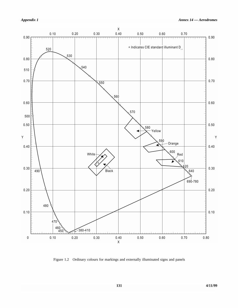
Appendix 1 Annex 14 — Aerodromes
131 4/11/99
Figure 1.2 Ordinary colours for markings and externally illuminated signs and panels

Annex 14 — Aerodromes Volume I
4/11/99 132
Figure 1.3 Colours of retro-reflective materials for markings, signs and panels

STD.ICAO ANNEX I9 VOL I-ENGL I,999 - 48’fLlllb OZ0902b 971 -
Appendix I Annex I4 - Aerodromes
X
0.10 0.20 0.30 0.40 0.50 0.60 0.70 0.90
0.80
SIC
0.70
0.60
5oc
0.50
Y
0.40
0.30
0.20
0.10
0
llll~lllr
540 \
\
WHITE (DAY) _
lllI~llr
350 -
\
51
/ , / / I 9 t / / /
BLACK
+ Indicates CIE standard illuminant D,js
570
+ 4
’ I L
I
-u’
WHITE (NIGHT)
-
i_ )W
1 I I I 1 I I I L 0.30
0.80
0.70
0.60
i
0.50 -
Y
0.40
0.50 -
Y
d 0.40
RED
.O 0.30 0.30
k 640
190-760 1
0.20 -I
ii
0.20
0.10 0.10
Figure 1.4 Colours of transilluminated (internally illuminated) signs and panels
133 4/l l/99

STD.ICAO ANNEX l,L( VOL I-ENGL 1979 m rl8lllllrlnb 0307ll27 808 m
APPENDIX 2. AERONAUTIC&L GROUND LIGHT CHARACTERISTICS
Degrees vertical
16.5
2.5 1.5
0 -20 -15 -14 -10 -5 0 5 10 14 15 20 X
Degrees horizontal
Notes:
1. Curves calculated on formula
2. Vertical setting angles of the lights shall be such that the following vertical coverage of the main beam will be met:
distance from threshold vertical main beam coverage
threshold to 315 m 00 - 110 316 m to 475 m 0.50 - Il.50 476 m to 640 m 1.50 - 12.50 641 m and beyond 2.5O - 13.5O (as illustrated above)
3. Lights in crossbars beyond 22.5 m from the centre line shall be toed-in 2 degrees. All other lights shall be aligned parallel to the centre line of the runway.
4. See collective notes for Figures 2.1 to 2.11.
411 l/99 134 ANNEX I4 ~ VOLlJME I
Figure 2. I Isocandela diagram for approach ccntrc line light and crossbars (white light)

STD=ICAO ANNEX Llr VOL I-ENGL I,999 - '+il'dl,qLb OlO=iO28 7'4'4 M
Appendix 2 Annex 14 - Aerodromes
Degrees vertical
Minimum
Degrees horizontal
Notes:
1. Curves calculated on formula
2. Toe-in 2 degrees
3. Vertical setting angles of the lights shall be such that the following vertical coverage of the main beam will be met:
distance from threshold vertical main beam coverage
threshold to 115 m 0.50 - 10.50 116 m to 215 m 10 - 110 216 m and beyond l.!Y - 11.5O (as illustrated above)
4. See collective notes for Figures 2.1 to 2.11.
Figure 2.2 Isocandela diagram for approach side row light (red light)
135 4/l 1199

STD.ICAO ANNEX Lq VOL I-ENGL l,‘=l=l=l U ‘i8’4lrlLb 030702=l b8O W
Annex 14 - Aerodromes
11.5
10
! I I I I I i I I I
- I i I I i I I I I ttA+t
Degrees vertical
Y
5
1 0 -5. IL
Volume Z
-15 -10 -9 -7.5 -5.5 -5 0 5 5.5 7.5 9 10 15 X
Degrees horizontal
Notes:
1. Curves calculated on formula
2. Toe-in 3.5 degrees
3. See collective notes for Figures 2.1 to 2.11.
Figure 2.3 Isocandela diagram for threshold light (green light)
4/l l/99 136

STD.ICAO ANNEX I,4 VOL I-ENGL lt=l=l=l W ‘48LIla~Lh 01107030 3T2 -
Appendix 2 Annex 14 - Aerodromes
Degrees vertical
I Yt
m
,dR Minimum
I, a-1nnnrt-4 15
13.5
11.5 10.5
Ill,,
- t- El T
minimum 5 000 cd
, / I I 5 7 10 11 .5
Degrees horizontal
Notes:
1. Curves calculated on formula
2. Toe-in 2 degrees
3. See collective notes for Figures 2.1 to 2.11
Figure 2.4 Isocandela diagram for threshold wing bar light (green light)
137 4/11/99
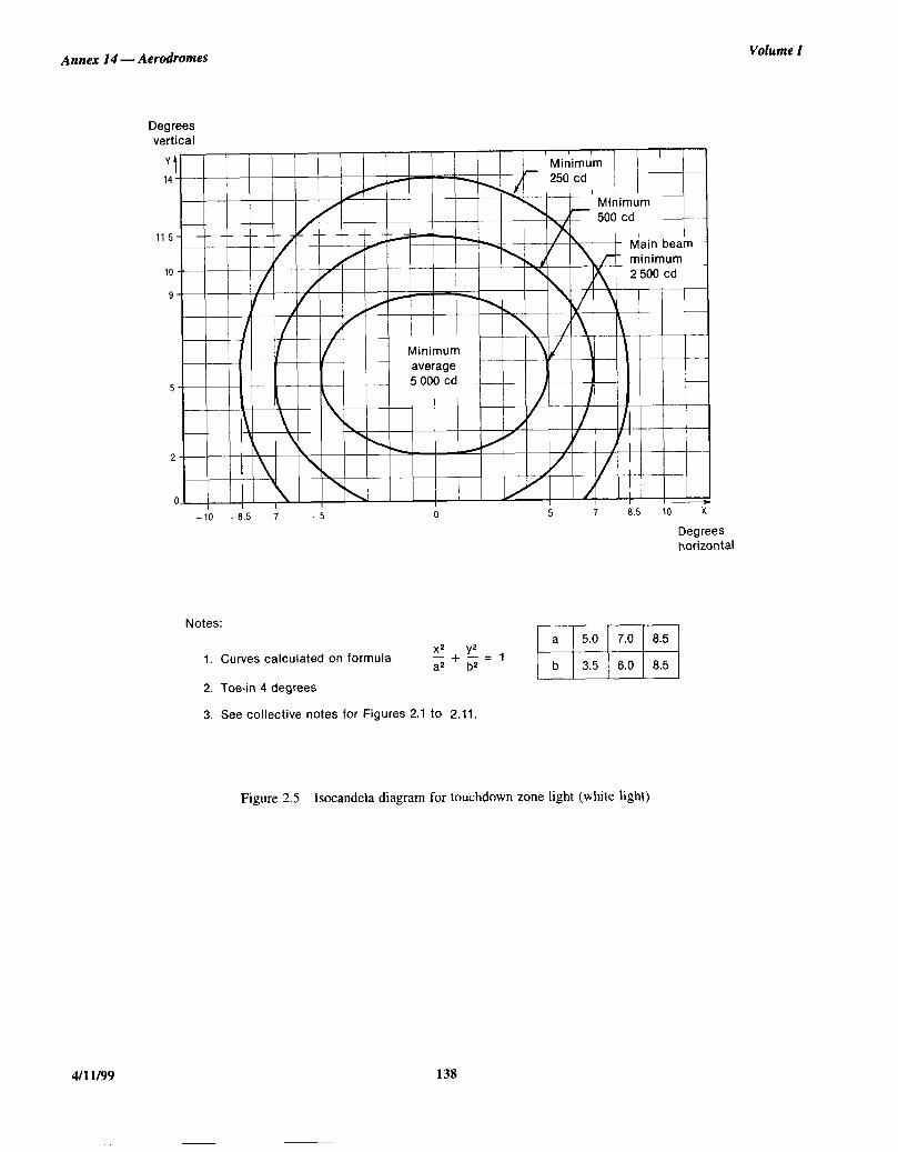
STD.ICAO ANNEX l1’4 VOL I-ENGL I,777 m 4811L4Lb lll,OqO3l, 239 m
Annex 14 -
Degrees vertical
-10 -8.5 -7 -5
Degrees horizontal
Volume 1
Notes:
1. Curves calculated on formula
2. Toe-in 4 degrees
3. See collective notes for Figures 2.1 to 2.11.
Figure 2.5 Isocandela diagram for touchdown zone light (white light)
4/11/99 138
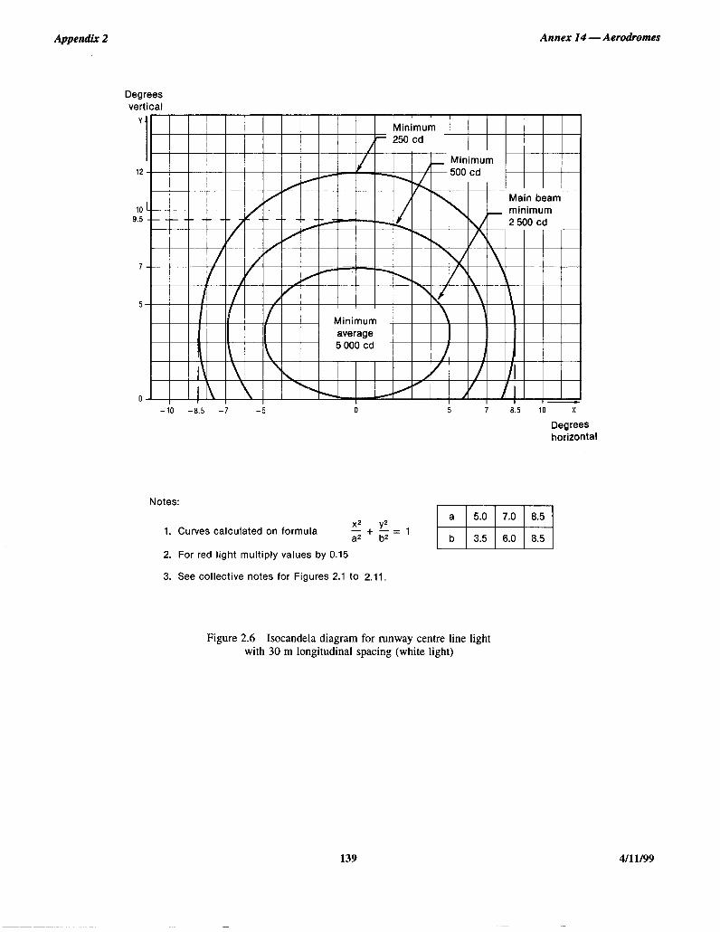
STD~ICAO ANNEX III vow I-ENGL L999 m 48wu nwh03z 175 m
Appendix 2 Annex 14 - Aerodromes
Degrees vertical
Yfl I I I I I I I I I I I I / I ” I I I I I II Minimum 1
II / / / / / / / / j / iii j I I /
Minimum l2""""" p I I I
I I I
10 9.5
7
-lb -8.5 -f 0 ; a.5 10 x
Degrees horizontal
Notes:
1. Curves calculated on formula
2. For red light multiply values by 0.15
3. See collective notes for Figures 2.1 to 2.11.
Figure 2.6 Isocandela diagram for runway centre line light with 30 m longitudinal spacing (white light)
139 4/l 1199

STD.ICA~ ANNEX 14 voL I-ENGL L777 m 48uub 0307033 001 m
Annex 14 - Aerodromes
Degrees vertical
13 1 250 cd for Cat. I 125 cd for Cat. I I I I
t i I iO0 cd for Cat. III ,cn ..A z-- e-1 I
10
.t
’ 5. I II II I
/
s 0 I Y 1 I
-10 -8.5 -7 -5 ;
iii (
8.5 X 10
Degrees horizontal
Notes:
1. Curves calculated on formula
2. For red light multiply values by 0.15
3. See collective notes for Figures 2.1 to 2.11
Volume Z
Figure 2.7 Isocandela diagram for runway centre line light with 15 m longitudinal spacing (white light)
4/l l/99 140

STD.ICAO ANNEX In4 VOL I;ENGL I,999 m 98lrLIILb fJl,O=lO3'4 T’IB m
Appendix 2 Annex I4 - Aerodromes
Degrees vertical
0.25
-10 -9 -7.5 -6 -5 0 5 6 7.5 9 10 X
Degrees horizontal
Notes:
1. Curves calculated on formula
2. See collective notes for Figures 2.1 to 2.11.
Figure 2.8 Isocandela diagram for runway end light (red light)
141 4/l 1199

STD.ICAO ANNEX 14 voL I-ENGL I2777 m w3wu 0307035 78q m
Annex 14 - Aerodromes Volume I
Degrees vertical
12
10'
w i
7.5 9 10 X
Degrees horizontal
Notes:
1. Curves calculated on formula
2. Toe-in 3.5 degrees
3. For yellow light multiply values by 0.4
4. See collective notes for Figures 2.1 to 2.11.
Figure 2.9 Isocandela diagram for runway edge light where width of runway is 45 m (white light)
4/l 1199 142

STD.ICAO ANNEX It4 VOL I-ENGL I,999 W ‘4B~la’iLb OLll=lll3b ttL0 M
Appendix 2 Annex 14 - Aerodromes
Degrees vertical
A I
/l-- -- -- :A=~ /
I’ I
7--
5--- i I-YTt
0 L!i
Main beam mum - 3 cd
-815 4.5 -i 6 i.5 s
1 .5 io- >
Degrees horizontal
Notes:
1. Curves calculated on formula
2. Toe-in 4.5 degrees
3. For yellow light multiply values by 0.4
4. See collective notes for Figures 2.1 to 2.11.
Figure 2.10 Isocandela diagram for runway edge light where width of runway is 60 m (white light)
143 4/11/99

STD.ICAO ANNEX LL( VOL I-ENGL 1999 - 484L'dlb 0309037 757 D
Annex 14 - Aerodromes Volume I
Degrees vertical
Yf 8
7 I I I I I --
6 AH /
\
5 /'
4 / \
3 (
2 \
1 ! \\\ i /
I I
o---l--Yp---H I - 1
+ -7 - 6 -5 -4 -3 -2 - 10123456 7 x
Degrees horizontal
Figure 2.11 Grid points to be used for the calculation of average intensity of approach and runway lights
4/l l/99 144

Appendix 2 Annex 14 — Aerodromes
145 4/11/99
Collective notes to Figures 2.1 to 2.11
1. The ellipses in each figure are symmetrical about the common vertical and horizontal axes.
2. Figures 2.1 to 2.10 show the minimum allowable light intensities. The average intensity of the main beam is calculated byestablishing grid points as shown in Figure 2.11 and using the intensity values measures at all grid points located within and on theperimeter of the ellipse representing the main beam. The average value is the arithmetic average of light intensities measured at allconsidered grid points.
3. No deviations are acceptable in the main beam pattern when the lighting fixture is properly aimed.
4. Average intensity ratio. The ratio between the average intensity within the ellipse defining the main beam of a typical new lightand the average light intensity of the main beam of a new runway edge light shall be as follows:
5. The beam coverages in the figures provide the necessary guidance for approaches down to an RVR of the order of 150 m andtake-offs down to an RVR of the order of 100 m.
6. Horizontal angles are measured with respect to the vertical plane through the runway centre line. For lights other than centreline lights, the direction towards the runway centre line is considered positive. Vertical angles are measured with respect to thehorizontal plane.
7. Where, for approach centre line lights and crossbars and for approach side row lights, inset lights are used in lieu of elevatedlights, e.g. on a runway with a displaced threshold, the intensity requirements can be met by installing two or three fittings (lowerintensity) at each position.
8. The importance of adequate maintenance cannot be over-emphasized. The average intensity should never fall to a value lessthan 50 per cent of the value shown in the figures and it should be the aim of airport authorities to maintain a level of light output closeto the specified minimum average intensity.
9. The light unit shall be installed so that the main beam is aligned within one-half degree of the specified requirement.
Figure 2.1 Approach centre line and crossbars 1.5 to 2.0 (white light)
Figure 2.2 Approach side row 0.5 to 1.0 (red light)
Figure 2.3 Threshold 1.0 to 1.5 (green light)
Figure 2.4 Threshold wing bar 1.0 to 1.5 (green light)
Figure 2.5 Touchdown zone 0.5 to 1.0 (white light)
Figure 2.6 Runway centre line (longitudinal spacing 30 m) 0.5 to 1.0 (white light)
Figure 2.7 Runway centre line (longitudinal spacing 15 m) 0.5 to 1.0 for CAT III(white light)
0.25 to 0.5 for CAT I, II(white light)
Figure 2.8 Runway end 0.25 to 0.5 (red light)
Figure 2.9 Runway edge (45 m runway width) 1.0 (white light)
Figure 2.10 Runway edge (60 m runway width) 1.0 (white light)
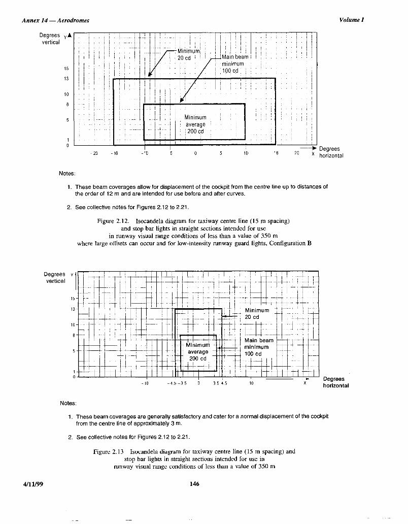
STD.ICAO ANNEX l1’4 VOL I-ENGL I,779 - q8’4l14Lb 0309039 52T D
Annex I4 - Aerodromes
Degrees Y vertical A
15
13
10
0
5
0
! j , i + I i
minimum : i 10(),--j ;j””
20 -16 -io -5 0 5 10 16 20 x
Volume I
Degrees horizontal
Notes:
1. These beam coverages allow for displacement of the cockpit from the centre line up to distances of the order of 12 m and are intended for use before and after curves.
2. See collective notes for Figures 2.12 to 2.21.
Figure 2.12. Isocandela diagram for taxiway centre line (15 m spacing) and stop bar lights in straight sections intended for use
in runway visual range conditions of less than a value of 350 m where large offsets can occur and for low-intensity runway guard lights, Configuration B
-10 -4.5 -3.5 0 3 5 4.5 10 X Degrees horizontal
Notes:
1. These beam coverages are generally satisfactory and cater for a normal displacement of the cockpit from the centre line of approximately 3 m.
2. See collective notes for Figures 2.12 to 2.21.
Figure 2.13 Isocandela diagram for taxiway centre line (15 m spacing) and stop bar lights in straight sections intended for use in
runway visual range conditions of less than a value of 350 m
4/l 1199 146

STD.ICAO ANNEX 14 VOL I-ENGL 1977 m 48qLL(lb 0l,070’40 24L a
Appendix 2 Annex I4 - Aerodromes
Degrees Y
vertical 1
15
Degrees vertical
-21.25 -19.25 -15 -10 -5 0 5 IO 15 19.25 21.25
-
Jotes:
1. Lights on curves to be toed-in 15.75 degrees with respect to the tangent of the curve.
2. See collective notes for Figures .2.12 to 2.21.
Figure 2.14 Isocandela diagram for taxiway centre line (7.5 m spacing) and stop bar lights in curved sections intended for use in
runway visual range conditions of less than a value of 350 m
‘tl I I I I / I / I I I l I I I i I I I / III ~ ill1 1
I 111111lIllil VII, ~~~~IIIllIIlllilll~~~~~~~~~
I I ) I I I Minimum averaoe 20 cd I I I I I I I I I
Notes:
1. At locations where high background luminance is usual and where deterioration of light output resulting from dust, snow and local contamination is a significant factor, the cd- values should be multiplied by 2.5.
2. Where omnidirectional lights are used they shall comply with the vertical beam requirements in this figure.
3. See collective notes for Figures 2.12 to 2.21
Degrees horizontal
horizontal
Figure 2.15 Isocandela diagram for taxiway centre line (30 m, 60 m spacing) and stop bar lights in straight sections intended for use in runway visual range conditions of 350 m or greater
147 4/l l/99

STDmICAO ANNEX LL( VOL I-ENGL L=l=l=l - LJBL(/L(Lb lll,O9Cl~l, I,&8 m
Annex I4 - Aerodromes Volume I
0.54-l I I!;,;;;; ;i;;;;;;; ~; I /! I I ~ j; I1 j; I 11 I I I I I
-20.25 -19.25 -15 -10 -5 0 5 10 15 19.25 20.25 7 Degrees
horizontal Notes:
1. Lights on curves to be toed-in 15.75 degrees with respect to the tangent of the curve.
2. At locations where high background luminance is usual and where deterioration of light output resulting from dust, snow and local contamination is a significant factor, the cd- values should be multiplied by 2.5.
3. These beam coverages allow for displacement of the cockpit from the centre line up to distances of the order of 12 m as could occur at the end of curves.
4. See collective notes for Figures 2.12 to 2.21.
Figure 2.16 Isocandela diagram for taxiway centre line (7.5 m, 1.5 m, 30 m spacing) and stop bar lights in curved sections intended for use in runway visual range conditions of 350 m or greater
4/l 1199 148
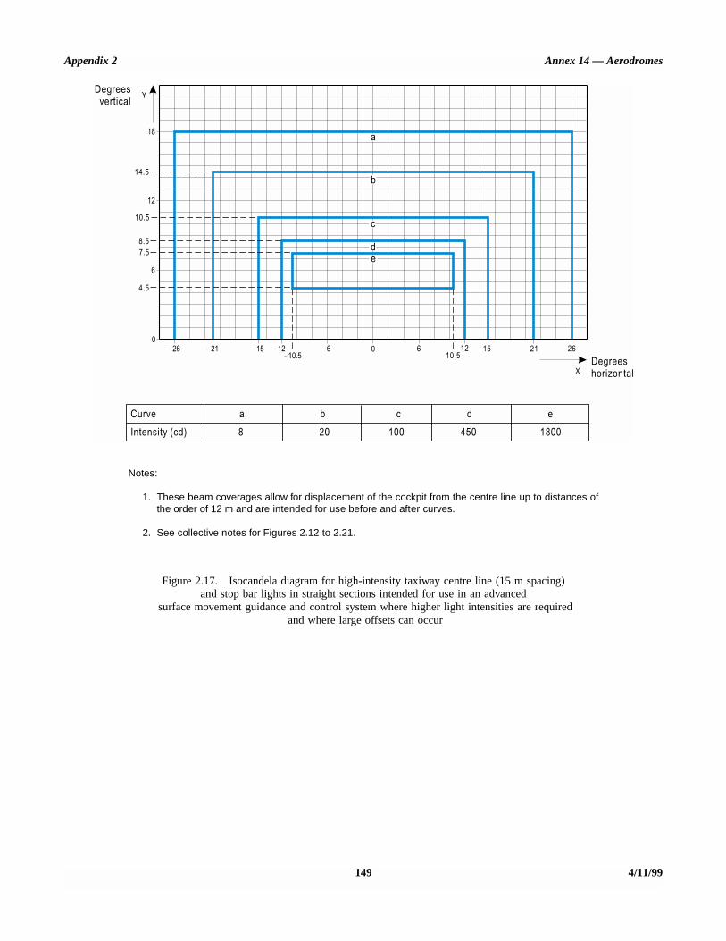
Appendix 2 Annex 14 — Aerodromes
149 4/11/99
Notes:
1. These beam coverages allow for displacement of the cockpit from the centre line up to distances ofthe order of 12 m and are intended for use before and after curves.
2. See collective notes for Figures 2.12 to 2.21.
Figure 2.17. Isocandela diagram for high-intensity taxiway centre line (15 m spacing)and stop bar lights in straight sections intended for use in an advanced
surface movement guidance and control system where higher light intensities are required and where large offsets can occur

Annex 14 — Aerodromes Volume I
4/11/99 150
Notes:
1. These beam coverages are generally satisfactory and cater for a normal displacement of the cockpitcorresponding to the outer main gear wheel on the taxiway edge.
2. See collective notes for Figures 2.12 to 2.21.
Figure 2.18. Isocandela diagram for high-intensity taxiway centre line (15 m spacing)and stop bar lights in straight sections intended for use in an advanced
surface movement guidance and control system where higher light intensities are required

Appendix 2 Annex 14 — Aerodromes
151 4/11/99
Notes:
1. Lights on curves to be toed-in 17 degrees with respect to the tangent of the curve.
2. See collective notes for Figures 2.12 to 2.21.
Figure 2.19. Isocandela diagram for high-intensity taxiway centre line (7.5 m spacing)and stop bar lights in curved sections intended for use in an advanced
surface movement guidance and control system where higher light intensities are required
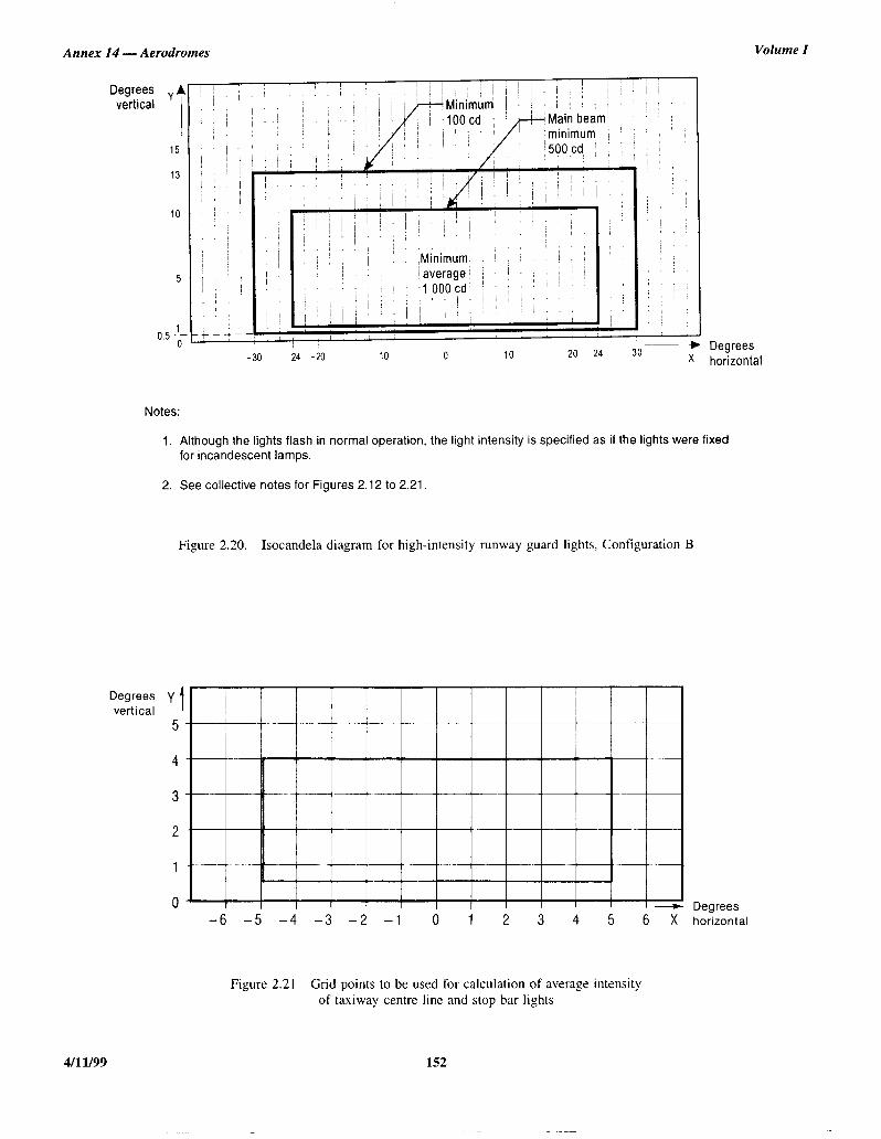
STDmICAO ANNEX I,9 VOL I-ENGL I,997 II qBLiltYl,b OLlJ=lO45 823 M
Annex 14 - Aerodromes
Degrees y vertical
T 15
13
IO
5
Notes:
Degrees horizontal
Degrees
Volume I
1. Although the lights flash in normal operation, the light intensity is specified as if the lights were fixed for incandescent lamps.
2. See collective notes for Figures 2.12 to 2.21.
Figure 2.20. Isocandela diagram for high-intensity runway guard lights, Configuration B
Degrees -6 -5 -4 -3 -2 -1 0 1 2 3 4 5 6 X horizontal
Figure 2.21 Grid points to be used for calculation of average intensity of taxiway centre line and stop bar lights
4/l l/99 152

Appendix 2 Annex 14 — Aerodromes
153 4/11/99
Collective notes to Figures 2.12 to 2.21
1. The intensities specified in Figures 2.12 to 2.20 are in green and yellow light for taxiway centre line lights, yellow light forrunway guard lights and red light for stop bar lights.
2. Figures 2.12 to 2.20 show the minimum allowable light intensities. The average intensity of the main beam is calculated byestablishing grid points as shown in Figure 2.21 and using the intensity values measured at all grid points located within and onthe perimeter of the rectangle representing the main beam. The average value is the arithmetic average of the light intensitiesmeasured at all considered grid points.
3. No deviations are acceptable in the main beam or in the innermost beam, as applicable, when the lighting fixture is properlyaimed.
4. Horizontal angles are measured with respect to the vertical plane through the taxiway centre line except on curves wherethey are measured with respect to the tangent to the curve.
5. Vertical angles are measured from the longitudinal slope of the taxiway surface.
6. The importance of adequate maintenance cannot be over-emphasized. The intensity, either average where applicable or asspecified on the corresponding isocandela curves, should never fall to a value less than 50 per cent of the value shown in the f iguresand it should be the aim of airport authorities to maintain a level of light output close to the specified minimum average intensity.
7. The light unit shall be installed so that the main beam or the innermost beam, as applicable, is aligned within one-half degreeof the specified requirement.
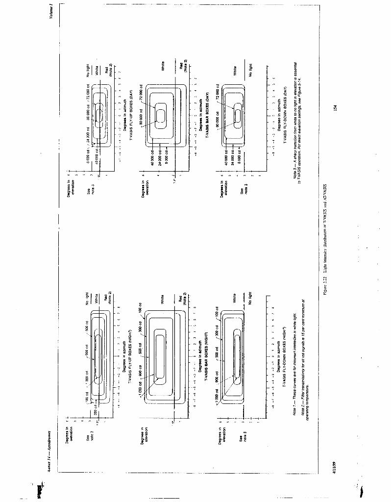
STD.ICAO ANNEX I,4 VOL I-ENGL I,999 - ~84L41b OLll=lO’l7 bTb - .-._. .---- _---~- __. -~~-_______
r

STDmICAO ANNEX l,Ll VOL I-ENGL l,=l=l=l B qdql,ql,b ~l,nqO’iij 532 m
Appendix 2 Annex 14 - Aerodromes
Degrees in elevation
4.5 I I 4 I 3.5 I - I 1 3
K.” 0
White
Red
-15 -14 -12 -10 -8 -6 -4 -2 0 2 4 6 8 10 12 14 15
Degrees in azimuth
Note 1.- These curves are for minimum intensities in red light.
Note 2.- The intensity value in the white sector of the beam is no less than 2 and may be as high as 6.5 times the corresponding intensity in the red sector.
Note 3.- The intensity values shown in brackets are for APAPI.
-
Figure 2.23 Light intensity distribution of PAP1 and APMI
155 4/l 1199
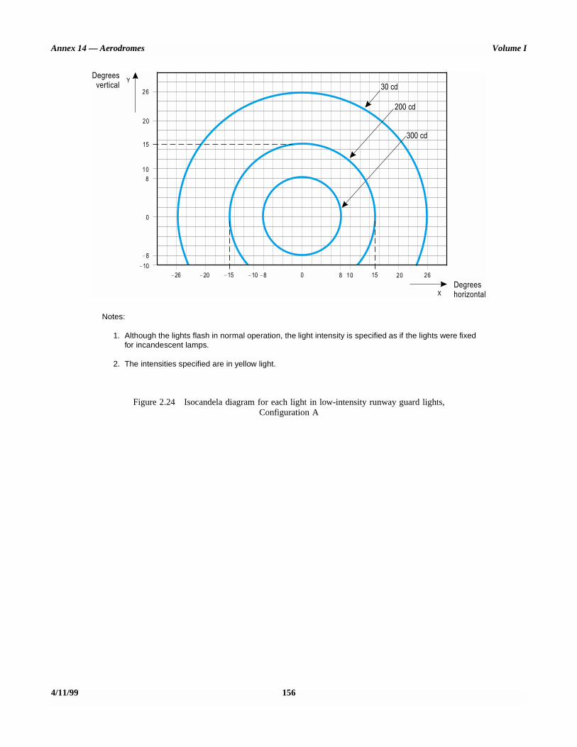
Annex 14 — Aerodromes Volume I
4/11/99 156
Notes:
1. Although the lights flash in normal operation, the light intensity is specified as if the lights were fixedfor incandescent lamps.
2. The intensities specified are in yellow light.
Figure 2.24 Isocandela diagram for each light in low-intensity runway guard lights,Configuration A
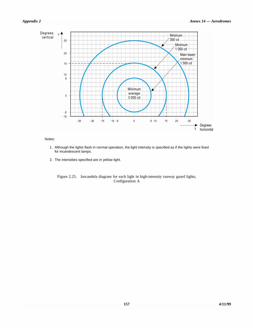
Appendix 2 Annex 14 — Aerodromes
157 4/11/99
Notes:
1. Although the lights flash in normal operation, the light intensity is specified as if the lights were fixedfor incandescent lamps.
2. The intensities specified are in yellow light.
Figure 2.25. Isocandela diagram for each light in high-intensity runway guard lights, Configuration A

APPENDIX 3. MANDATORY INSTRUCTION MARKINGS ANDINFORMATION MARKINGS
Note 1.— See Chapter 5, Sections 5.2.15 and 5.2.16 forspecifications on the application, location and characteristicsof mandatory instruction markings and information markings.
Note 2.— This appendix details the form and proportions ofthe letters, numbers and symbols of mandatory instructionmarkings and information markings on a 20 cm grid.
4/11/99 158 ANNEX 14 — VOLUME I

Appendix 3 Annex 14 — Aerodromes
159 4/11/99

Annex 14 — Aerodromes Volume I
4/11/99 160

Appendix 3 Annex 14 — Aerodromes
161 4/11/99
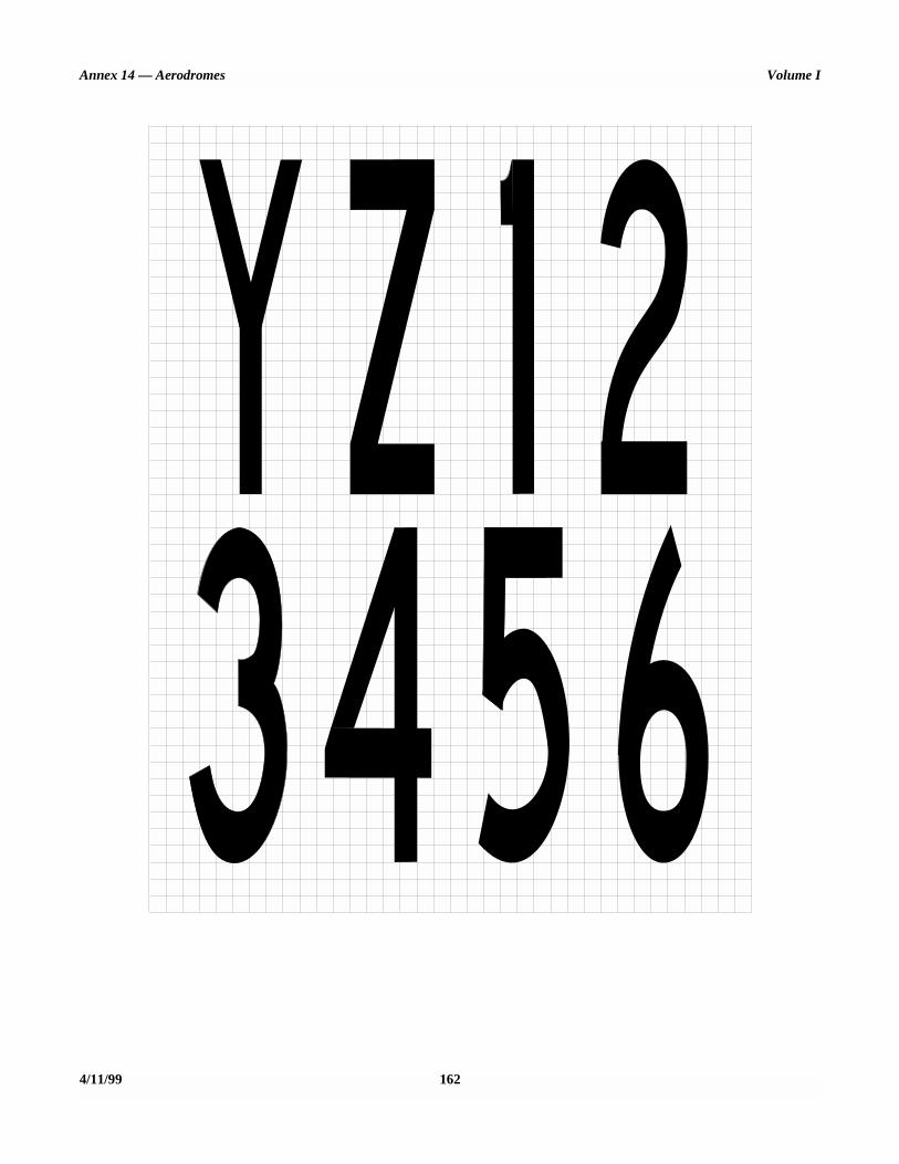
Annex 14 — Aerodromes Volume I
4/11/99 162

Appendix 3 Annex 14 — Aerodromes
163 4/11/99
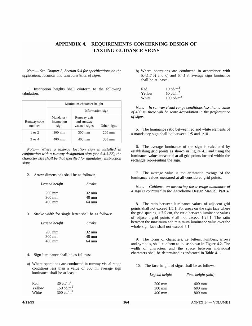
APPENDIX 4. REQUIREMENTS CONCERNING DESIGN OFTAXIING GUIDANCE SIGNS
Note.— See Chapter 5, Section 5.4 for specifications on theapplication, location and characteristics of signs.
1. Inscription heights shall conform to the followingtabulation.
Note.— Where a taxiway location sign is installed inconjunction with a runway designation sign (see 5.4.3.22), thecharacter size shall be that specified for mandatory instructionsigns.
2. Arrow dimensions shall be as follows:
Legend height Stroke
200 mm 32 mm300 mm 48 mm400 mm 64 mm
3. Stroke width for single letter shall be as follows:
Legend height Stroke
200 mm 32 mm300 mm 48 mm400 mm 64 mm
4. Sign luminance shall be as follows:
a) Where operations are conducted in runway visual rangeconditions less than a value of 800 m, average signluminance shall be at least:
Red 30 cd/m2
Yellow 150 cd/m2
White 300 cd/m2
b) Where operations are conducted in accordance with5.4.1.7 b) and c) and 5.4.1.8, average sign luminanceshall be at least:
Red 10 cd/m2
Yellow 50 cd/m2
White 100 cd/m2
Note.— In runway visual range conditions less than a valueof 400 m, there will be some degradation in the performanceof signs.
5. The luminance ratio between red and white elements ofa mandatory sign shall be between 1:5 and 1:10.
6. The average luminance of the sign is calculated byestablishing grid points as shown in Figure 4.1 and using theluminance values measured at all grid points located within therectangle representing the sign.
7. The average value is the arithmetic average of theluminance values measured at all considered grid points.
Note.— Guidance on measuring the average luminance ofa sign is contained in the Aerodrome Design Manual, Part 4.
8. The ratio between luminance values of adjacent gridpoints shall not exceed 1.5:1. For areas on the sign face wherethe grid spacing is 7.5 cm, the ratio between luminance valuesof adjacent grid points shall not exceed 1.25:1. The ratiobetween the maximum and minimum luminance value over thewhole sign face shall not exceed 5:1.
9. The forms of characters, i.e. letters, numbers, arrowsand symbols, shall conform to those shown in Figure 4.2. Thewidth of characters and the space between individualcharacters shall be determined as indicated in Table 4.1.
10. The face height of signs shall be as follows:
Legend height Face height (min)
200 mm 400 mm300 mm 600 mm400 mm 800 mm
Runway code number
Minimum character height
Mandatory instruction
sign
Information sign
Runway exit and runway
vacated signs Other signs
1 or 2 300 mm 300 mm 200 mm
3 or 4 400 mm 400 mm 300 mm
4/11/99 164 ANNEX 14 — VOLUME I

Appendix 4 Annex 14 — Aerodromes
11. The face width of signs shall be determined usingFigure 4.3 except that, where a mandatory instruction sign isprovided on one side of a taxiway only, the face width shallnot be less than:
a) 1.94 m where the code number is 3 or 4; and
b) 1.46 m where the code number is 1 or 2.
Note.— Additional guidance on determining the face widthof a sign is contained in the Aerodrome Design Manual, Part 4.
12. Borders
a) The black vertical delineator between adjacent directionsigns should have a width of approximately 0.7 of thestroke width.
b) The yellow border on a stand-alone location sign shouldbe approximately 0.5 stroke width.
13. The colours of signs shall be in accordance with theappropriate specifications in Appendix 1.
165 4/11/99
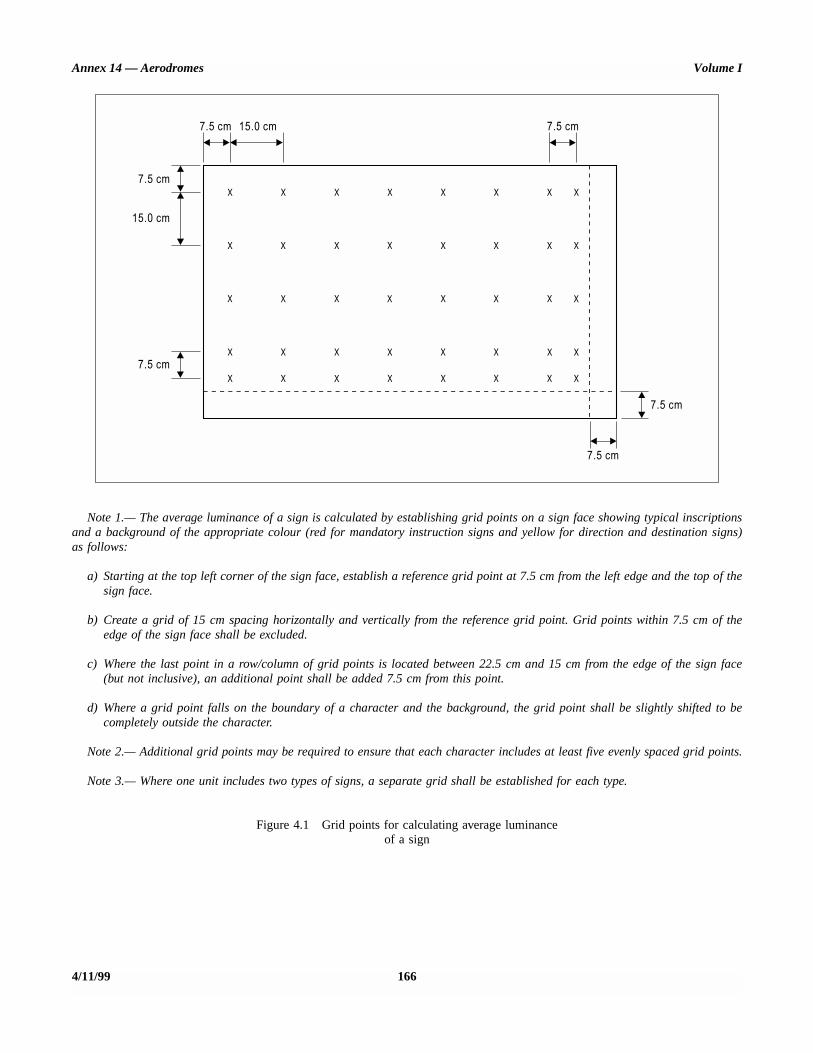
Annex 14 — Aerodromes Volume I
4/11/99 166
Note 1.— The average luminance of a sign is calculated by establishing grid points on a sign face showing typical inscriptionsand a background of the appropriate colour (red for mandatory instruction signs and yellow for direction and destination signs)as follows:
a) Starting at the top left corner of the sign face, establish a reference grid point at 7.5 cm from the left edge and the top of thesign face.
b) Create a grid of 15 cm spacing horizontally and vertically from the reference grid point. Grid points within 7.5 cm of theedge of the sign face shall be excluded.
c) Where the last point in a row/column of grid points is located between 22.5 cm and 15 cm from the edge of the sign face(but not inclusive), an additional point shall be added 7.5 cm from this point.
d) Where a grid point falls on the boundary of a character and the background, the grid point shall be slightly shifted to becompletely outside the character.
Note 2.— Additional grid points may be required to ensure that each character includes at least five evenly spaced grid points.
Note 3.— Where one unit includes two types of signs, a separate grid shall be established for each type.
Figure 4.1 Grid points for calculating average luminanceof a sign
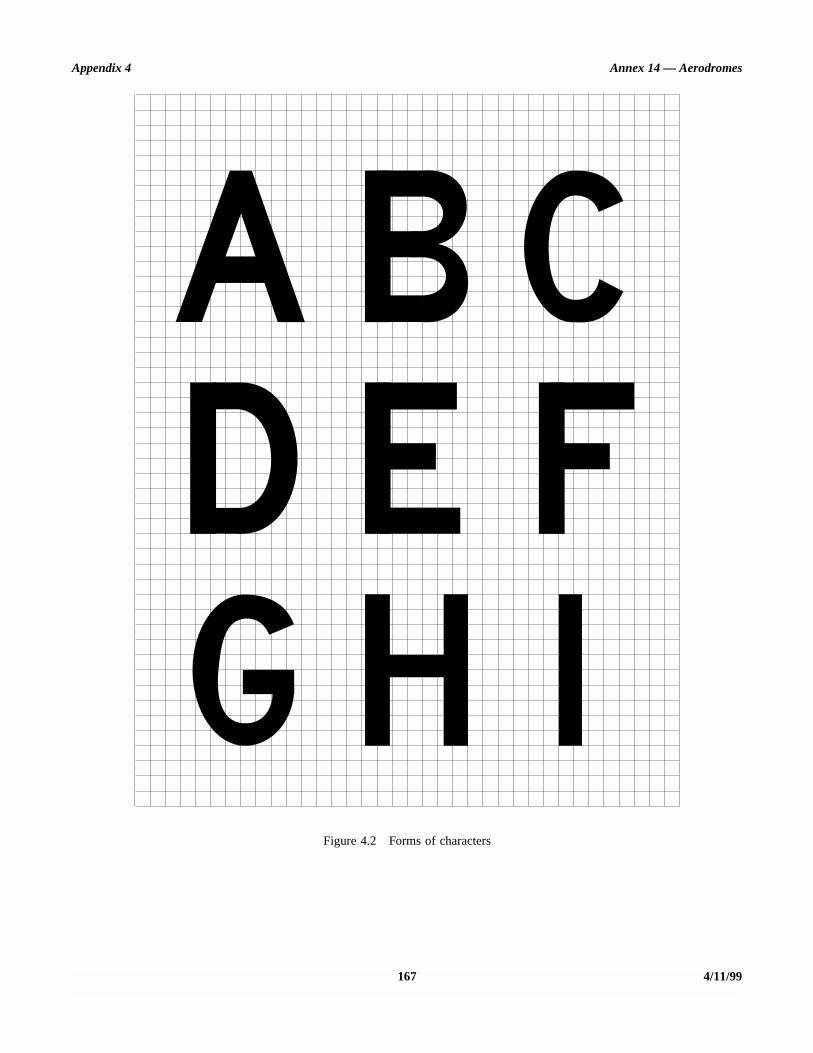
Appendix 4 Annex 14 — Aerodromes
167 4/11/99
Figure 4.2 Forms of characters

Annex 14 — Aerodromes Volume I
4/11/99 168
Figure 4.2 (cont.)

Appendix 4 Annex 14 — Aerodromes
169 4/11/99
Figure 4.2 (cont.)
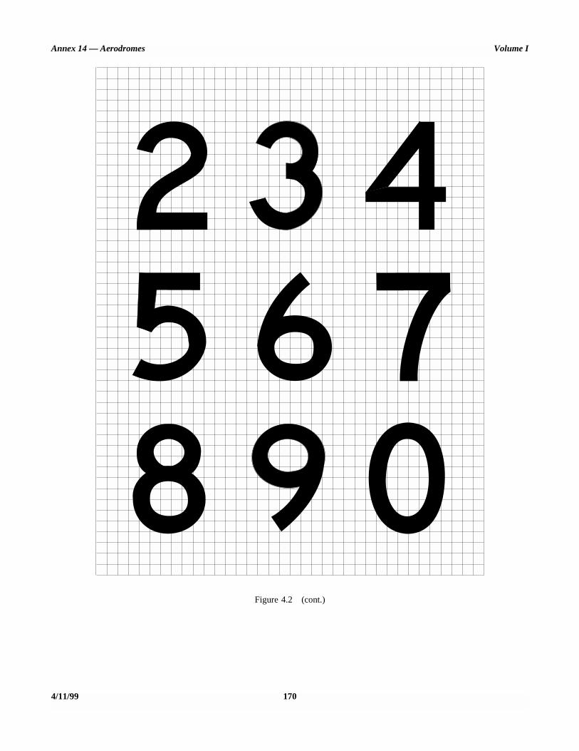
Annex 14 — Aerodromes Volume I
4/11/99 170
Figure 4.2 (cont.)

Appendix 4 Annex 14 — Aerodromes
171 4/11/99
Figure 4.2 (cont.)

Annex 14 — Aerodromes Volume I
4/11/99 172
Figure 4.2 (cont.)
Note 1.— The arrow stroke width, diameter of the dot, and bothwidth and length of the dash shall be proportioned to the characterstroke widths.
Note 2.— The dimensions of the arrow shall remain constant fora particular sign size, regardless of orientation.

Appendix 4 Annex 14 — Aerodromes
173 4/11/99
Table 4-1. Letter and numeral widths and space between letters or numerals
INSTRUCTIONS
1. To determine the proper SPACE between letters or numerals, obtainthe code number from table a or b and enter table c for that codenumber to the desired letter or numeral height.
2. The space between words or groups of characters forming anabbreviation or symbol should be equal to 0.5 to 0.75 of the heightof the characters used except that where an arrow is located with asingle character such as ‘A →‘, the space may be reduced to notless than one quarter of the character of the height in order toprovide a good visual balance.
3. Where the numeral follows a letter or vice versa use Code 1.4. Where a hyphen, dot, or diagonal stroke follows a character or vice
versa use Code 1.
a) Letter to letter code number
PrecedingLetter
Following Letter
B, D, E, F,H, I, K, L,
M, N, P, R, UC, G, O,
Q, S, X, ZA, J, T,V, W, Y
Code number
A 2 2 4B 1 2 2C 2 2 3D 1 2 2E 2 2 3F 2 2 3G 1 2 2H 1 1 2I 1 1 2J 1 1 2K 2 2 3L 2 2 4M 1 1 2N 1 1 2O 1 2 2P 1 2 2Q 1 2 2R 1 2 2S 1 2 2T 2 2 4U 1 1 2V 2 2 4W 2 2 4X 2 2 3Y 2 2 4Z 2 2 3
b) Numeral to numeral code number
PrecedingNumeral
Following number
1, 52, 3, 6,8, 9, 0 4, 7
Code number
1 1 1 22 1 2 23 1 2 24 2 2 45 1 2 26 1 2 27 2 2 48 1 2 29 1 2 20 1 2 2
c) Space between characters
Code No.
Letter Height (mm)200 300 400
Space (mm)
1 48 71 962 38 57 763 25 38 504 13 19 26
d) Width of letter
Letter
Letter height (mm)200 300 400
Width (mm)
A 170 255 340B 137 205 274C 137 205 274D 137 205 274E 124 186 248F 124 186 248G 137 205 274H 137 205 274I 32 48 64J 127 190 254K 140 210 280L 124 186 248M 157 236 314N 137 205 274O 143 214 286P 137 205 274Q 143 214 286R 137 205 274S 137 205 274T 124 186 248U 137 205 274V 152 229 304W 178 267 356X 137 205 274Y 171 257 342Z 137 205 274
e) Width of numeral
Letter
Numeral height (mm)200 300 400
Width (mm)
1 50 74 982 137 205 2743 137 205 2744 149 224 2985 137 205 2746 137 205 2747 137 205 2748 137 205 2749 137 205 2740 143 214 286
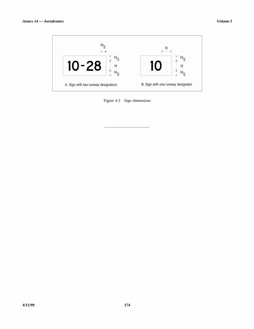
Annex 14 — Aerodromes Volume I
4/11/99 174
Figure 4.3 Sign dimensions

APPENDIX 5. AERONAUTICAL DATA QUALITY REQUIREMENTS
Table 1. Latitude and longitude
Latitude and longitudeAccuracyData type
ClassificationIntegrity
Aerodrome reference point . . . . . . . . . . . . . . . . . . . . . . 30 msurveyed/calculated
routine1 × 10-3
NAVAIDS located at the aerodrome . . . . . . . . . . . . . . 3 msurveyed
essential1 × 10-5
Obstacles in the circling area and at the aerodrome . . . . . . . . . . . . . . . . . . . . . . . . . . . . . .
3 msurveyed
essential1 × 10-5
Significant obstacles in the approach and take-off area . . . . . . . . . . . . . . . . . . . . . . . . . . . . . . . . . .
3 msurveyed
essential1 × 10-5
Runway threshold . . . . . . . . . . . . . . . . . . . . . . . . . . . . . 1 msurveyed
critical1 × 10-8
Runway end(flight path alignment point) . . . . . . . . . . . . . . . . . . . . .
1 msurveyed
critical1 × 10-8
Runway centre line points. . . . . . . . . . . . . . . . . . . . . . . 1 msurveyed
critical1 × 10-8
Taxiway centre line points . . . . . . . . . . . . . . . . . . . . . . 0.5 msurveyed
essential1 × 10-5
Aircraft stand-points/INS check-points. . . . . . . . . . . . . 0.5 msurveyed
routine1 × 10-3
ANNEX 14 — VOLUME I 175 4/11/99

Annex 14 — Aerodromes Volume I
Table 2. Elevation/Altitude/Height
Table 3. Declination and magnetic variation
Elevation/altitude/heightAccuracyData type
ClassificationIntegrity
Aerodrome elevation . . . . . . . . . . . . . . . . . . . . . . . . . . . 0.5 m or 1 ftsurveyed
essential1 × 10-5
WGS-84 geoid undulation at aerodrome elevation position. . . . . . . . . . . . . . . . . . . . . . . . . . . . . .
0.5 m or 1 ftsurveyed
essential1 × 10-5
Runway threshold, non-precision approaches. . . . . . . . 0.5 m or 1 ftsurveyed
essential1 × 10-5
WGS-84 geoid undulation at runway threshold, non-precision approaches . . . . . . . . . . . . . . . . . . . . . . .
0.5 m or 1 ftsurveyed
essential1 × 10-5
Runway threshold, precision approaches . . . . . . . . . . . 0.25 m or 1 ftsurveyed
critical1 × 10-8
WGS-84 geoid undulation at runway threshold,precision approaches . . . . . . . . . . . . . . . . . . . . . . . . . . .
0.25 m or 1 ftsurveyed
critical1 × 10-8
Obstacles in the approach and take-off areas . . . . . . . . 1 m or 1 ftsurveyed
essential1 × 10-5
Obstacles in the circling areas and at the aerodrome . . . . . . . . . . . . . . . . . . . . . . . . . . . . . .
1 m or 1 ftsurveyed
essential1 × 10-5
Distance measuring equipment/precision (DME/P). . . . . . . . . . . . . . . . . . . . . . . . . . . . . . . . . . . . .
3 m (10 ft)surveyed
essential1 × 10-5
Declination/variationAccuracyData type
ClassificationIntegrity
Aerodrome magnetic variation . . . . . . . . . . . . . . . . . . . 1 degreesurveyed
essential1 × 10-5
ILS localizer antenna magnetic variation . . . . . . . . . . . 1 degreesurveyed
essential1 × 10-5
MLS azimuth antenna magnetic variation . . . . . . . . . . 1 degreesurveyed
essential1 × 10-5
4/11/99 176

Appendix 5 Annex 14 — Aerodromes
Table 4. Bearing
Table 5. Length/Distance/Dimension
BearingAccuracyData type
ClassificationIntegrity
ILS localizer alignment . . . . . . . . . . . . . . . . . . . . . . . . . 1/100 degreesurveyed
essential1 × 10-5
MLS zero azimuth alignment . . . . . . . . . . . . . . . . . . . . 1/100 degreesurveyed
essential1 × 10-5
Runway bearing . . . . . . . . . . . . . . . . . . . . . . . . . . . . . . . 1/100 degreesurveyed
routine1 × 10-3
Length/distance/dimensionAccuracyData type
ClassificationIntegrity
Runway length . . . . . . . . . . . . . . . . . . . . . . . . . . . . . . . . 1 m or 1 ftsurveyed
critical1 × 10-8
Stopway length . . . . . . . . . . . . . . . . . . . . . . . . . . . . . . . 1 m or 1 ftsurveyed
critical1 × 10-8
Landing distance available . . . . . . . . . . . . . . . . . . . . . . 1 m or 1 ftsurveyed
critical1 × 10-8
ILS localizer antenna-runway end, distance . . . . . . . . . 3 m (10 ft)calculated
routine1 × 10-3
ILS glide slope antenna-threshold, distance along centre line . . . . . . . . . . . . . . . . . . . . . . .
3 m (10 ft)calculated
routine1 × 10-3
ILS markers-threshold distance. . . . . . . . . . . . . . . . . . . 3 m (10 ft)calculated
essential1 × 10-5
ILS DME antenna-threshold, distance along centre line . . . . . . . . . . . . . . . . . . . . . . .
3 m (10 ft)calculated
essential1 × 10-5
MLS azimuth antenna-runway end, distance . . . . . . . . 3 m (10 ft)calculated
routine1 × 10-3
MLS elevation antenna-threshold, distance along centre line . . . . . . . . . . . . . . . . . . . . . . .
3 m (10 ft)calculated
routine1 × 10-3
MLS DME/P antenna-threshold, distance along centre line . . . . . . . . . . . . . . . . . . . . . . .
3 m (10 ft)calculated
essential1 × 10-5
177 4/11/99
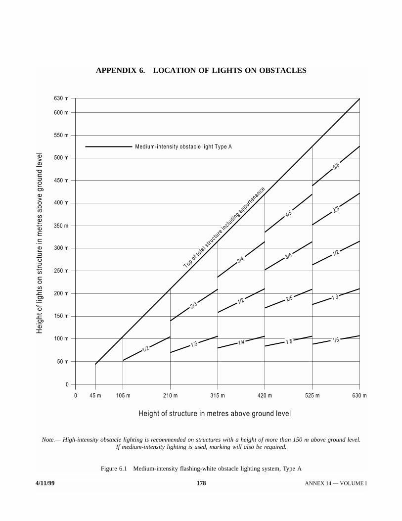
4/11/99 178 ANNEX 14 — VOLUME I
APPENDIX 6. LOCATION OF LIGHTS ON OBSTACLES
Note.— High-intensity obstacle lighting is recommended on structures with a height of more than 150 m above ground level.If medium-intensity lighting is used, marking will also be required.
Figure 6.1 Medium-intensity flashing-white obstacle lighting system, Type A

Appendix 6 Annex 14 — Aerodromes
179 4/11/99
Note.— For night-time use only.
Figure 6.2 Medium-intensity flashing-red obstacle lighting system, Type B

Annex 14 — Aerodromes Volume I
4/11/99 180
Note.— For night-time use only.
Figure 6.3 Medium-intensity fixed-red obstacle lighting system, Type C
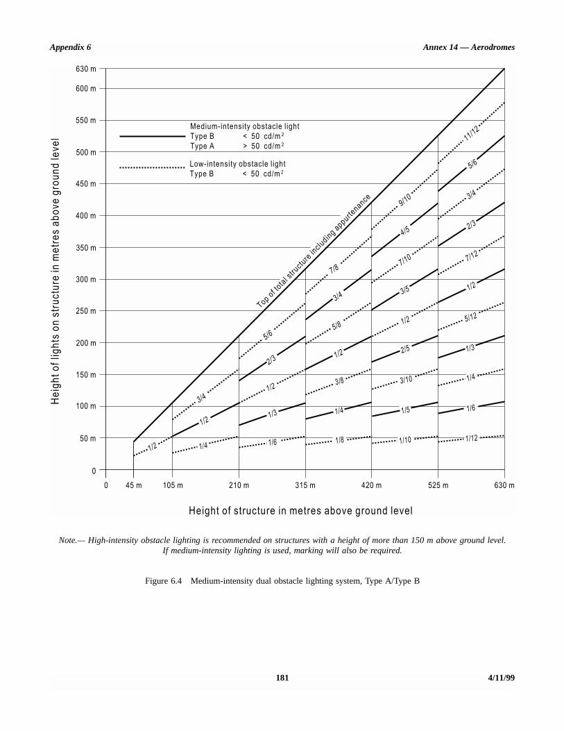
Appendix 6 Annex 14 — Aerodromes
181 4/11/99
Note.— High-intensity obstacle lighting is recommended on structures with a height of more than 150 m above ground level.If medium-intensity lighting is used, marking will also be required.
Figure 6.4 Medium-intensity dual obstacle lighting system, Type A/Type B

Annex 14 — Aerodromes Volume I
4/11/99 182
Note.— High-intensity obstacle lighting is recommended on structures with a height of more than 150 m above ground level.If medium-intensity lighting is used, marking will also be required.
Figure 6.5 Medium-intensity dual obstacle lighting system, Type A/Type C
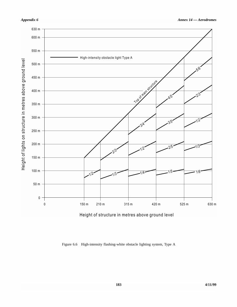
Appendix 6 Annex 14 — Aerodromes
183 4/11/99
Figure 6.6 High-intensity flashing-white obstacle lighting system, Type A

Annex 14 — Aerodromes Volume I
4/11/99 184
Figure 6.7 High-/medium-intensity dual obstacle lighting system, Type A/Type B
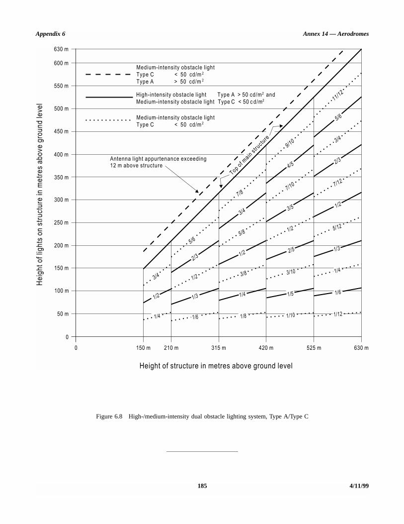
Appendix 6 Annex 14 — Aerodromes
185 4/11/99
Figure 6.8 High-/medium-intensity dual obstacle lighting system, Type A/Type C

ATTACHMENT A. GUIDANCE MATERIALSUPPLEMENTARY TO ANNEX 14, VOLUME I
1. Number, siting and orientation of runways
Siting and orientation of runways
1.1 Many factors should be taken into account in thedetermination of the siting and orientation of runways. With-out attempting to provide an exhaustive list of these factors noran analysis of their effects, it appears useful to indicate thosewhich most frequently require study. These factors may beclassified under four headings:
1.1.1 Type of operation. Attention should be paid inparticular to whether the aerodrome is to be used in allmeteorological conditions or only in visual meteorologicalconditions, and whether it is intended for use by day and night,or only by day.
1.1.2 Climatological conditions. A study of the winddistribution should be made to determine the usability factor.In this regard, the following comments should be taken intoaccount:
a) Wind statistics used for the calculation of the usabilityfactor are normally available in ranges of speed anddirection, and the accuracy of the results obtaineddepends, to a large extent, on the assumed distributionof observations within these ranges. In the absence ofany sure information as to the true distribution, it isusual to assume a uniform distribution since, in relationto the most favourable runway orientations, thisgenerally results in a slightly conservative figure for theusability factor.
b) The maximum mean cross-wind components given inChapter 3, 3.1.2 refer to normal circumstances. Thereare some factors which may require that a reduction ofthose maximum values be taken into account at a par-ticular aerodrome. These include:
1) the wide variations which may exist, in handlingcharacteristics and maximum permissible cross-windcomponents, among diverse types of aeroplanes(including future types) within each of the threegroups given in 3.1.2;
2) prevalence and nature of gusts;
3) prevalence and nature of turbulence;
4) the availability of a secondary runway;
5) the width of runways;
6) the runway surface conditions — water, snow and iceon the runway materially reduce the allowable cross-wind component; and
7) the strength of the wind associated with the limitingcross-wind component.
A study should also be made of the occurrence of poor visi-bility and/or low cloud base. Account should be taken of theirfrequency as well as the accompanying wind direction andspeed.
1.1.3 Topography of the aerodrome site, its approaches,and surroundings, particularly:
a) compliance with the obstacle limitation surfaces;
b) current and future land use. The orientation and layoutshould be selected so as to protect as far as possible theparticularly sensitive areas such as residential, schooland hospital zones from the discomfort caused by air-craft noise;
c) current and future runway lengths to be provided;
d) construction costs; and
e) possibility of installing suitable non-visual and visualaids for approach-to-land.
1.1.4 Air traffic in the vicinity of the aerodrome,particularly:
a) proximity of other aerodromes or ATS routes;
b) traffic density; and
c) air traffic control and missed approach procedures.
Number of runways in each direction
1.2 The number of runways to be provided in each direc-tion depends on the number of aircraft movements to becatered to.
2. Clearways and stopways
2.1 The decision to provide a stopway and/or a clearwayas an alternative to an increased length of runway will dependon the physical characteristics of the area beyond the runway
ANNEX 14 — VOLUME I 187 4/11/99

Annex 14 — Aerodromes Volume I
end, and on the operating performance requirements of theprospective aeroplanes. The runway, stopway and clearwaylengths to be provided are determined by the aeroplane take-off performance, but a check should also be made of thelanding distance required by the aeroplanes using the runwayto ensure that adequate runway length is provided for landing.The length of a clearway, however, cannot exceed half thelength of take-off run available.
2.2 The aeroplane performance operating limitationsrequire a length which is enough to ensure that the aeroplanecan, after starting a take-off, either be brought safely to a stopor complete the take-off safely. For the purpose of discussionit is supposed that the runway, stopway and clearway lengthsprovided at the aerodrome are only just adequate for theaeroplane requiring the longest take-off and accelerate-stopdistances, taking into account its take-off mass, runwaycharacteristics and ambient atmospheric conditions. Underthese circumstances there is, for each take-off, a speed, calledthe decision speed; below this speed, the take-off must beabandoned if an engine fails, while above it the take-off mustbe completed. A very long take-off run and take-off distancewould be required to complete a take-off when an engine failsbefore the decision speed is reached, because of theinsufficient speed and the reduced power available. Therewould be no difficulty in stopping in the remaining accelerate-stop distance available provided action is taken immediately.In these circumstances the correct course of action would be toabandon the take-off.
On the other hand, if an engine fails after the decision speedis reached, the aeroplane will have sufficient speed and poweravailable to complete the take-off safely in the remaining take-off distance available. However, because of the high speed,there would be difficulty in stopping the aeroplane in theremaining accelerate-stop distance available.
2.3 The decision speed is not a fixed speed for anyaeroplane, but can be selected by the pilot within limits to suitthe accelerate-stop and take-off distance available, aeroplanetake-off mass, runway characteristics, and ambient atmosphericconditions at the aerodrome. Normally, a higher decision speedis selected as the accelerate-stop distance available increases.
2.4 A variety of combinations of accelerate-stop distancesrequired and take-off distances required can be obtained toaccommodate a particular aeroplane, taking into account theaeroplane take-off mass, runway characteristics, and ambientatmospheric conditions. Each combination requires its par-ticular length of take-off run.
2.5 The most familiar case is where the decision speed issuch that the take-off distance required is equal to theaccelerate-stop distance required; this value is known as thebalanced field length. Where stopway and clearway are notprovided, these distances are both equal to the runway length.However, if landing distance is for the moment ignored,runway is not essential for the whole of the balanced fieldlength, as the take-off run required is, of course, less than the
balanced field length. The balanced field length can, therefore,be provided by a runway supplemented by an equal length ofclearway and stopway, instead of wholly as a runway. If therunway is used for take-off in both directions, an equal lengthof clearway and stopway has to be provided at each runwayend. The saving in runway length is, therefore, bought at thecost of a greater over-all length.
2.6 In case economic considerations preclude the pro-vision of stopway and, as a result, only runway and clearwayare to be provided, the runway length (neglecting landingrequirements) should be equal to the accelerate-stop distancerequired or the take-off run required, whichever is the greater.The take-off distance available will be the length of therunway plus the length of clearway.
2.7 The minimum runway length and the maximum stop-way or clearway length to be provided may be determined asfollows, from the data in the aeroplane flight manual for theaeroplane considered to be critical from the viewpoint ofrunway length requirements:
a) if a stopway is economically possible, the lengths to beprovided are those for the balanced field length. Therunway length is the take-off run required or the landingdistance required, whichever is the greater. If theaccelerate-stop distance required is greater than therunway length so determined, the excess may be pro-vided as stopway, usually at each end of the runway. Inaddition, a clearway of the same length as the stopwaymust also be provided;
b) if a stopway is not to be provided, the runway length isthe landing distance required, or if it is greater, theaccelerate-stop distance required, which corresponds tothe lowest practical value of the decision speed. Theexcess of the take-off distance required over the runwaylength may be provided as clearway, usually at each endof the runway.
2.8 In addition to the above consideration, the concept ofclearways in certain circumstances can be applied to asituation where the take-off distance required for all enginesoperating exceeds that required for the engine failure case.
2.9 The economy of a stopway can be entirely lost if, aftereach usage, it must be regraded and compacted. Therefore, itshould be designed to withstand at least a certain number ofloadings of the aeroplane which the stopway is intended toserve without inducing structural damage to the aeroplane.
3. Calculation of declared distances
3.1 The declared distances to be calculated for eachrunway direction comprise: the take-off run available (TORA),take-off distance available (TODA), accelerate-stop distanceavailable (ASDA), and landing distance available (LDA).
4/11/99 188

Attachment A Annex 14 — Aerodromes
3.2 Where a runway is not provided with a stopway orclearway and the threshold is located at the extremity of therunway, the four declared distances should normally be equalto the length of the runway, as shown in Figure A-1 (A).
3.3 Where a runway is provided with a clearway (CWY),then the TODA will include the length of clearway, as shownin Figure A-1 (B).
3.4 Where a runway is provided with a stopway (SWY),then the ASDA will include the length of stopway, as shownin Figure A-1 (C).
3.5 Where a runway has a displaced threshold, then theLDA will be reduced by the distance the threshold is dis-placed, as shown in Figure A-1 (D). A displaced thresholdaffects only the LDA for approaches made to that threshold;all declared distances for operations in the reciprocal directionare unaffected.
3.6 Figures A-1 (B) through A-1 (D) illustrate a runwayprovided with a clearway or a stopway or having a displacedthreshold. Where more than one of these features exist, thenmore than one of the declared distances will be modified —but the modification will follow the same principle illustrated.An example showing a situation where all these features existis shown in Figure A-1 (E).
3.7 A suggested format for providing information ondeclared distances is given in Figure A-1 (F). If a runway di-rection cannot be used for take-off or landing, or both, becauseit is operationally forbidden, then this should be declared andthe words “not usable” or the abbreviation “NU” entered.
4. Slopes on a runway
4.1 Distance between slope changes
The following example illustrates how the distance betweenslope changes is to be determined (see Figure A-2):
D for a runway where the code number is 3 should be atleast:
15 000 (|x – y| + |y – z|) m|x – y| being the absolute numerical value of x – y|y – z| being the absolute numerical value of y – z
Assuming x = + 0.01Assuming y = –0.005Assuming z = +0.005then |x – y| = 0.015then |y – z| = 0.01
To comply with the specifications, D should be not lessthan:
that is, 15 000 (0.015 + 0.01) m,that is, 15 000 × 0.025 = 375 m
4.2 Consideration of longitudinal andtransverse slopes
When a runway is planned that will combine the extremevalues for the slopes and changes in slope permitted underChapter 3, 3.1.12 to 3.1.18, a study should be made to ensurethat the resulting surface profile will not hamper the operationof aeroplanes.
4.3 Radio altimeter operating area
In order to accommodate aeroplanes making auto-coupledapproaches and automatic landings (irrespective of weatherconditions) it is desirable that slope changes be avoided orkept to a minimum, on a rectangular area at least 300 m longbefore the threshold of a precision approach runway. The areashould be symmetrical about the extended centre line, 120 mwide. When special circumstances so warrant, the width maybe reduced to no less than 60 m if an aeronautical studyindicates that such reduction would not affect the safety ofoperations of aircraft. This is desirable because these aero-planes are equipped with a radio altimeter for final height andflare guidance, and when the aeroplane is above the terrainimmediately prior to the threshold, the radio altimeter willbegin to provide information to the automatic pilot for auto-flare. Where slope changes cannot be avoided, the rate ofchange between two consecutive slopes should not exceed2 per cent per 30 m.
5. Runway surface evenness
5.1 In adopting tolerances for runway surface irregu-larities, the following standard of construction is achievablefor short distances of 3 m and conforms to good engineeringpractice:
Except across the crown of a camber or across drainagechannels, the finished surface of the wearing course is to beof such regularity that, when tested with a 3 m straight-edge placed anywhere in any direction on the surface, thereis no deviation greater than 3 mm between the bottom ofthe straight-edge and the surface of the pavement anywherealong the straight edge.
5.2 Caution should also be exercised when insertingrunway lights or drainage grilles in runway surfaces to ensurethat adequate smoothness of the surface is maintained.
5.3 The operation of aircraft and differential settlement ofsurface foundations will eventually lead to increases in surfaceirregularities. Small deviations in the above tolerances will notseriously hamper aircraft operations. In general, isolated irregu-larities of the order of 2.5 cm to 3 cm over a 45 m distance aretolerable. Exact information of the maximum acceptable devi-ation cannot be given, as it varies with the type and speed ofan aircraft.
189 4/11/99

STD.ICAO ANNEX I,4 VOL I-ENGL I,999 - qB914Lb OLO9L1i32 7TO E
Annex I4 - Aerodromes Volume I
B CWY TORA
e
D
Note.- All declared distances are itiustrated for operations from left to right
RUNWAY -s3
RUNWAY f TORA 1 ASDA / TODA 1 LDA 1
In m m m
09 2 000 2 300 2 580 I 1850
Figure A-l. Illustration of declared distances
4/11/99
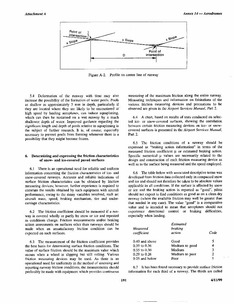
STD=ICAO ANNEX /II VOL I-ENGL I,‘799 E '484l,4l,b CJl,O=lll83 b37 m
Attachment A Annex I4 - Aerodromes
Point of intersection
Figure A-2. Profile on centre line of runway
5.4 Deformation of the runway with time may also increase the possibility of the formation of water pools. Pools as shallow as approximately 3 mm in depth, particularly if they are located where they are likely to be encountered at high speed by landing aeroplanes, can induce aquaplaning, which can then be sustained on a wet runway by a much shallower. depth of water. Improved guidance regarding the significant length and depth of pools relative to aquaplaning is the subject of further research. It is, of course, especially necessary to prevent pools from forming whenever there is a possibility that they might become frozen.
6. Determining and expressing the friction characteristics of snow- and ice-covered paved surfaces
6.1 There is an operational need for reliable and uniform information concerning the friction characteristics of ice- and snow-covered runways. Accurate and reliable indications of surface friction characteristics can be obtained by friction measuring devices; however, further experience is required to correlate the results obtained by such equipment with aircraft performance, owing to the many variables involved, such as: aircraft mass, speed, braking mechanism, tire and under- carriage characteristics.
6.2 The friction coefficient should be measured if a run- way is covered wholly or partly by snow or ice and repeated as conditions change. Friction measurements and/or braking action assessments on surfaces other than runways should be made when an unsatisfactory friction condition can be expected on such surfaces.
6.3 The measurement of the friction coefficient provides the best basis for determining surface friction conditions. The value of surface friction should be the maximum value which occurs when a wheel is slipping but still rolling. Various friction measuring devices may be used. As there is an operational need for uniformity in the method of assessing and reporting runway friction conditions, the measurements should preferably be made with equipment which provides continuous
measuring of the maximum friction along the entire runway. Measuring techniques and information on limitations of the various friction measuring devices and precautions to be observed are given in the Airport Services Manual, Part 2.
6.4 A chart, based on results of tests conducted on selec- ted ice- or snow-covered surfaces, showing the correlation between certain friction measuring devices on ice- or snow- covered surfaces is presented in the Airport Services Manual, Part 2.
6.5 The friction conditions of a runway should be expressed as “braking action information” in terms of the measured friction coefficient p or estimated braking action. Specific numerical p values are necessarily related to the design and construction of each friction measuring device as well as to the surface being measured and the speed employed.
6.6 The table below with associated descriptive terms was developed from friction data collected only in compacted snow and ice and should not therefore be taken to be absolute values applicable in all conditions. If the surface is affected by snow or ice and the braking action is reported as “good”, pilots should not expect to find conditions as good as on a clean dry runway (where the available friction may well be greater than that needed in any case). The value “good” is a comparative value and is intended to mean that aeroplanes should not experience directional control or braking difficulties, especially when landing.
Measured coeficient
Estimated braking action Code
0.40 and above Good 5 0.39 to 0.36 Medium to good 4 0.35 to 0.30 Medium 3 0.29 to 0.26 Medium to poor 2 0.25 and below Poor 1
6.7 It has been found necessary to provide surface friction information for each third of a runway. The thirds are called
191 4/11/99
Annex 14 — Aerodromes Volume I
A, B and C. For the purpose of reporting information toaeronautical service units, section A is always the sectionassociated with the lower runway designation number. Whengiving landing information to a pilot before landing, thesections are however referred to as first, second or third partof the runway. The first part always means the first third of therunway as seen in the direction of landing. Friction measure-ments are made along two lines parallel to the runway, i.e.along a line on each side of the centre line approximately 3 mor that distance from the centre line at which most operationstake place. The objective of the tests is to determine the meanfriction value for sections A, B and C. In cases where acontinuous friction measuring device is used, the mean valuesare obtained from the friction values recorded for each section.The distance between each test point should be approximately10 per cent of the usable length of the runway. If it is decidedthat a single test line on one side of the runway centre linegives adequate coverage of the runway, then it follows thateach third of the runway should have three tests carried out onit. Test results and calculated mean friction values are enteredin a special form (see Airport Services Manual, Part 2).
Note.— Where applicable, figures for stopway frictionvalue should also be made available on request.
6.8 A continuous friction measuring device (e.g.Skiddometer, Surface Friction Tester, Mu-meter, RunwayFriction Tester or Grip Tester), can be used for measuring thefriction values for compacted snow- and ice-covered runways.A decelerometer (e.g. Tapley Meter or Brakemeter — Dyno-meter) may be used on certain surface conditions, e.g.compacted snow, ice and very thin layers of dry snow. Otherfriction measuring devices can be used, provided they havebeen correlated with at least one of the types mentioned above.A decelerometer should not be used in loose snow or slush, asit can give misleading friction values. Other friction measuringdevices can also give misleading friction values under certaincombinations of contaminants and air/pavement temperature.
6.9 The Airport Services Manual, Part 2 provides guid-ance on the uniform use of test equipment to achievecompatible test results and other information on removal ofsurface contamination and improvement of friction conditions.
7. Determination of friction characteristicsof wet paved runways
7.1 The friction of a wet paved runway should bemeasured to:
a) verify the friction characteristics of new or resurfacedpaved runways when wet (Chapter 3, 3.1.23);
b) assess periodically the slipperiness of paved runwayswhen wet (Chapter 9, 9.4.5);
c) determine the effect on friction when drainage charac-teristics are poor (Chapter 9, 9.4.8); and
d) determine the friction of paved runways that becomeslippery under unusual conditions (Chapter 2, 2.9.8).
7.2 Runways should be evaluated when first constructedor after resurfacing to determine the wet runway surfacefriction characteristics. Although it is recognized that frictionreduces with use, this value will represent the friction of therelatively long central portion of the runway that is uncon-taminated by rubber deposits from aircraft operations and istherefore of operational value. Evaluation tests should be madeon clean surfaces. If it is not possible to clean a surface beforetesting, then for purposes of preparing an initial report a testcould be made on a portion of clean surface in the central partof the runway.
7.3 Friction tests of existing surface conditions should betaken periodically in order to identify runways with lowfriction when wet. A State should define what minimumfriction level it considers acceptable before a runway isclassified as slippery when wet and publish this value in theState’s aeronautical information publication (AIP). When thefriction of a runway is found to be below this reported value,then such information should be promulgated by NOTAM.The State should also establish a maintenance planning level,below which, appropriate corrective maintenance actionshould be initiated to improve the friction. However, when thefriction characteristics for either the entire runway or a portionthereof are below the minimum friction level, correctivemaintenance action must be taken without delay. Frictionmeasurements should be taken at intervals that will ensureidentification of runways in need of maintenance or specialsurface treatment before the condition becomes serious. Thetime interval between measurements will depend on factorssuch as: aircraft type and frequency of usage, climatic con-ditions, pavement type, and pavement service and maintenancerequirements.
7.4 For uniformity and to permit comparison with otherrunways, friction tests of existing, new or resurfaced runwaysshould be made with a continuous friction measuring deviceprovided with a smooth tread tire. The device should have acapability of using self-wetting features to enable measure-ments of the friction characteristics of the surface to be madeat a water depth of at least 1 mm.
7.5 When it is suspected that the friction characteristics ofa runway may be reduced because of poor drainage, owing toinadequate slopes or depressions, then an additional testshould be made, but this time under natural conditionsrepresentative of a local rain. This test differs from theprevious one in that water depths in the poorly cleared areasare normally greater in a local rain condition. The test resultsare thus more apt to identify problem areas having low frictionvalues that could induce aquaplaning than the previous test. Ifcircumstances do not permit tests to be conducted duringnatural conditions representative of a rain, then this conditionmay be simulated.
4/11/99 192

Attachment A Annex 14 — Aerodromes
7.6 Even when the friction has been found to be abovethe level set by the State to define a slippery runway, it maybe known that under unusual conditions, such as after a longdry period, the runway may have become slippery. When sucha condition is known to exist, then a friction measurementshould be made as soon as it is suspected that the runway mayhave become slippery.
7.7 When the results of any of the measurements ident-ified in 7.3 through 7.6 indicate that only a particular portionof a runway surface is slippery, then action to promulgate thisinformation and, if appropriate, take corrective action isequally important.
7.8 When conducting friction tests on wet runways, it isimportant to note that, unlike compacted snow and iceconditions, in which there is very limited variation of thefriction coefficient with speed, a wet runway produces a dropin friction with an increase in speed. However, as the speedincreases, the rate at which the friction is reduced becomes less.Among the factors affecting the friction coefficient between thetire and the runway surface, texture is particularly important. Ifthe runway has a good macro-texture allowing the water toescape beneath the tire, then the friction value will be lessaffected by speed. Conversely, a low macro-texture surface willproduce a larger drop in friction with increase in speed.Accordingly, when testing runways to determine their frictioncharacteristics and whether maintenance action is necessary toimprove it, a speed high enough to reveal these friction/speedvariations should be used.
7.9 Annex 14, Volume I requires States to specify twofriction levels as follows:
a) a maintenance friction level below which correctivemaintenance action should be initiated; and
b) a minimum friction level below which information thata runway may be slippery when wet should be madeavailable.
Furthermore, States should establish criteria for the frictioncharacteristics of new or resurfaced runway surfaces.Table A-1 provides guidance on establishing the design objec-tive for new runway surfaces and maintenance planning andminimum friction levels for runway surfaces in use.
7.10 The friction values given above are absolute valuesand are intended to be applied without any tolerance. Thesevalues were developed from a research study conducted in aState. The two friction measuring tires mounted on the Mu-meter were smooth tread and had a special rubber formulation,i.e. Type A. The tires were tested at a 15 degree included angleof alignment along the longitudinal axis of the trailer. Thesingle friction measuring tires mounted on the Skiddometer,Surface Friction Tester, Runway Friction Tester and TATRAwere smooth tread and used the same rubber formulation, i.e.Type B. The GRIPTESTER was tested with a single smoothtread tire having the same rubber formulation as Type B butthe size was smaller, i.e. Type C. The specifications of thesetires (i.e. Types A, B and C) are contained in the AirportServices Manual, Part 2. Friction measuring devices usingrubber formulation, tire tread/groove patterns, water depth, tirepressures, or test speeds different from those used in theprogramme described above, cannot be directly equatedwith the friction values given in the table. The values incolumns (5), (6) and (7) are averaged values representative of
193 4/11/99
Table A-1.
Test equipment
Test tire
Test speed(km/h)
Test waterdepth(mm)
Designobjectivefor newsurface
Maintenanceplanning
level
Minimumfriction
levelTypePressure
(kPa)
(1) (2) (3) (4) (5) (6) (7)
Mu-meter Trailer AA
7070
6595
1.01.0
0.720.66
0.520.38
0.420.26
Skiddometer Trailer BB
210210
6595
1.01.0
0.820.74
0.600.47
0.500.34
Surface FrictionTester Vehicle
BB
210210
6595
1.01.0
0.820.74
0.600.47
0.500.34
Runway FrictionTester Vehicle
BB
210210
6595
1.01.0
0.820.74
0.600.54
0.500.41
TATRA FrictionTester Vehicle
BB
210210
6595
1.01.0
0.760.67
0.570.52
0.480.42
GRIPTESTERTrailer
CC
140140
6595
1.01.0
0.740.64
0.530.36
0.430.24

Annex 14 — Aerodromes Volume I
the runway or significant portion thereof. It is considereddesirable to test the friction characteristics of a paved runwayat more than one speed.
7.11 Other friction measuring devices can be used,provided they have been correlated with at least one testequipment mentioned above. The Airport Services Manual,Part 2 provides guidance on the methodology for determiningthe friction values corresponding to the design objective,maintenance planning level and minimum friction level for afriction tester not identified in the above table.
8. Strips
8.1 Shoulders
8.1.1 The shoulder of a runway or stopway should beprepared or constructed so as to minimize any hazard to anaeroplane running off the runway or stopway. Some guidanceis given in the following paragraphs on certain special prob-lems which may arise, and on the further question of measuresto avoid the ingestion of loose stones or other objects byturbine engines.
8.1.2 In some cases, the bearing strength of the naturalground in the strip may be sufficient, without special prep-aration, to meet the requirements for shoulders. Where specialpreparation is necessary, the method used will depend on localsoil conditions and the mass of the aeroplanes the runway isintended to serve. Soil tests will help in determining the bestmethod of improvement (e.g. drainage, stabilization, surfacing,light paving).
8.1.3 Attention should also be paid when designingshoulders to prevent the ingestion of stones or other objects byturbine engines. Similar considerations apply here to thosewhich are discussed for the margins of taxiways in theAerodrome Design Manual, Part 2, both as to the specialmeasures which may be necessary and as to the distance overwhich such special measures, if required, should be taken.
8.1.4 Where shoulders have been treated specially, eitherto provide the required bearing strength or to prevent thepresence of stones or debris, difficulties may arise because ofa lack of visual contrast between the runway surface and thatof the adjacent strip. This difficulty can be overcome either byproviding a good visual contrast in the surfacing of the runwayor strip, or by providing a runway side stripe marking.
8.2 Objects on strips
Within the general area of the strip adjacent to the runway,measures should be taken to prevent an aeroplane’s wheel,when sinking into the ground, from striking a hard verticalface. Special problems may arise for runway light fittings or
other objects mounted in the strip or at the intersection witha taxiway or another runway. In the case of construction, suchas runways or taxiways, where the surface must also be flushwith the strip surface, a vertical face can be eliminated bychamfering from the top of the construction to not less than30 cm below the strip surface level. Other objects, thefunctions of which do not require them to be at surface level,should be buried to a depth of not less than 30 cm.
8.3 Grading of a strip for precisionapproach runways
Chapter 3, 3.3.8 recommends that the portion of a strip of aninstrument runway within at least 75 m from the centre lineshould be graded where the code number is 3 or 4. For aprecision approach runway, it may be desirable to adopt agreater width where the code number is 3 or 4. Figure A-3shows the shape and dimensions of a wider strip that may beconsidered for such a runway. This strip has been designedusing information on aircraft running off runways. The portionto be graded extends to a distance of 105 m from the centreline, except that the distance is gradually reduced to 75 m fromthe centre line at both ends of the strip, for a length of 150 mfrom the runway end.
9. Runway end safety areas
9.1 Where a runway end safety area is provided inaccordance with Chapter 3, consideration should be given toproviding an area long enough to contain overruns andundershoots resulting from a reasonably probable combinationof adverse operational factors. On a precision approachrunway, the ILS localizer is normally the first upstandingobstacle, and the runway end safety area should extend up tothis facility. In other circumstances and on a non-precisionapproach or non-instrument runway, the first upstandingobstacle may be a road, a railroad or other constructed ornatural feature. In such circumstances, the runway end safetyarea should extend as far as the obstacle.
9.2 Where provision of a runway end safety area mayinvolve encroachment in areas where it would be particularlyprohibitive to implement, and the appropriate authority con-siders a runway end safety area essential, consideration mayhave to be given to reducing some of the declared distances.
10. Location of threshold
10.1 General
10.1.1 The threshold is normally located at the extremityof a runway, if there are no obstacles penetrating above the
4/11/99 194
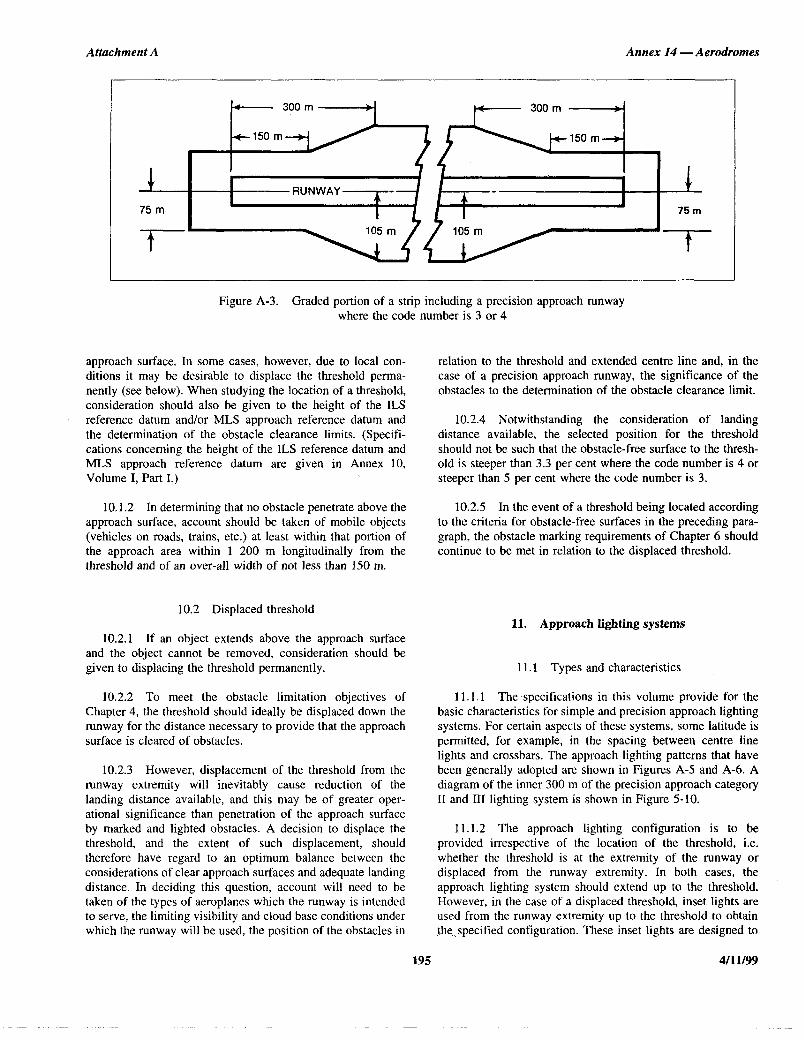
STD.ICAO ANNEX L'i VOL I-ENGL LS=l=i - 'it!iL(ltL(l,b 0307087 282 W
Attachment A Annex 14 - Aerodromes
- 300 m
J
75m
t
Figure A-3. Graded portion of a strip including a precision approach runway where the code number is 3 or 4
approach surface. In some cases, however, due to local con- ditions it may be desirable to displace the threshold perma- nently (see below). When studying the location of a threshold, consideration should also be given to the height of the ILS reference datum and/or MLS approach reference datum and the determination of the obstacle clearance limits. (Specifi- cations concerning the height of the ILS reference datum and MLS approach reference datum are given in Annex 10, Volume I, Part I.)
10.1.2 In determining that no obstacle penetrate above the approach surface, account should be taken of mobile objects (vehicles on roads, trains, etc.) at least within that portion of the approach area within 1 200 m longitudinally from the threshold and of an over-all width of not less than 150 m.
10.2 Displaced threshold
10.2.1 If an object extends above the approach surface and the object cannot be removed, consideration should be given to displacing the threshold permanently.
10.2.2 To meet the obstacle limitation objectives of Chapter 4, the threshold should ideally be displaced down the runway for the distance necessary to provide that the approach surface is cleared of obstacles.
10.2.3 However, displacement of the threshold from the runway extremity will inevitably cause reduction of the landing distance available, and this may be of greater oper- ational significance than penetration of the approach surface by marked and lighted obstacles. A decision to displace the threshold, and the extent of such displacement, should therefore have regard to an optimum balance between the considerations of clear approach surfaces and adequate landing distance. In deciding this question, account will need to be taken of the types of aeroplanes which the runway is intended to serve, the limiting visibility and cloud base conditions under which the runway will be used, the position of the obstacles in
relation to the threshold and extended centre line and, in the case of a precision approach runway, the significance of the obstacles to the determination of the obstacle clearance limit.
10.2.4 Notwithstanding the consideration of landing distance available, the selected position for the threshold should not be such that the obstacle-free surface to the thresh- old is steeper than 3.3 per cent where the code number is 4 or steeper than 5 per cent where the code number is 3.
10.2.5 In the event of a threshold being located according to the criteria for obstacle-free surfaces in the preceding para- graph, the obstacle marking requirements of Chapter 6 should continue to be met in relation to the displaced threshold.
11. Approach lighting systems
11.1 Types and characteristics
11 .l.l The specifications in this volume provide for the basic characteristics for simple and precision approach lighting systems. For certain aspects of these systems, some latitude is permitted, for example, in the spacing between centre line lights and crossbars. The approach lighting patterns that have been generally adopted are shown in Figures A-5 and A-6. A diagram of the inner 300 m of the precision approach category II and III lighting system is shown in Figure 5-10.
11.1.2 The approach lighting configuration is to be provided irrespective of the location of the threshold, i.e. whether the threshold is at the extremity of the runway or displaced from the runway extremity. In both cases, the approach lighting system should extend up to the threshold. However, in the case of a displaced threshold, inset lights are used from the runway extremity up to the threshold to obtain the.,specified configuration. These inset lights are designed to
195 4/u/99

Annex 14 — Aerodromes Volume I
satisfy the structural requirements specified in Chapter 5,5.3.1.8, and the photometric requirements specified in Appen-dix 2, Figure 2.1 or 2.2.
11.1.3 Flight path envelopes to be used in designing thelighting are shown in Figure A-4.
11.2 Installation tolerances
Horizontal
11.2.1 The dimensional tolerances are shown in Fig-ure A-6.
11.2.2 The centre line of an approach lighting systemshould be as coincident as possible with the extended centreline of the runway with a maximum tolerance of ± 15′.
11.2.3 The longitudinal spacing of the centre line lightsshould be such that one light (or group of lights) is located inthe centre of each crossbar, and the intervening centre linelights are spaced as evenly as practicable between two cross-bars or a crossbar and a threshold.
11.2.4 The crossbars and barrettes should be at rightangles to the centre line of the approach lighting system witha tolerance of ± 30′, if the pattern in Figure A-6 (A) is adoptedor ± 2°, if Figure A-6 (B) is adopted.
11.2.5 When a crossbar has to be displaced from itsstandard position, any adjacent crossbar should, wherepossible, be displaced by appropriate amounts in order toreduce the differences in the crossbar spacing.
11.2.6 When a crossbar in the system shown in Fig-ure A-6 (A) is displaced from its standard position, its over-all length should be adjusted so that it remains one-twentiethof the actual distance of the crossbar from the point of origin.It is not necessary, however, to adjust the standard 2.7 mspacing between the crossbar lights, but the crossbars shouldbe kept symmetrical about the centre line of the approachlighting.
Vertical
11.2.7 The ideal arrangement is to mount all the approachlights in the horizontal plane passing through the threshold(see Figure A-7), and this should be the general aim as far aslocal conditions permit. However, buildings, trees, etc., shouldnot obscure the lights from the view of a pilot who is assumedto be 1° below the electronic glide path in the vicinity of theouter marker.
11.2.8 Within a stopway or clearway, and within 150 mof the end of a runway, the lights should be mounted as nearto the ground as local conditions permit in order to minimizerisk of damage to aeroplanes in the event of an overrun or
undershoot. Beyond the stopway and clearway, it is not sonecessary for the lights to be mounted close to the ground andtherefore undulations in the ground contours can be compen-sated for by mounting the lights on poles of appropriate height.
11.2.9 It is desirable that the lights be mounted so that, asfar as possible, no object within a distance of 60 m on eachside of the centre line protrudes through the plane of theapproach lighting system. Where a tall object exists within60 m of the centre line and within 1 350 m from the thresholdfor a precision approach lighting system, or 900 m for a simpleapproach lighting system, it may be advisable to install thelights so that the plane of the outer half of the pattern clearsthe top of the object.
11.2.10 In order to avoid giving a misleading impressionof the plane of the ground, the lights should not be mountedbelow a gradient of 1 in 66 downwards from the threshold toa point 300 m out, and below a gradient of 1 in 40 beyond the300 m point. For a precision approach category II and IIIlighting system, more stringent criteria may be necessary, e.g.negative slopes not permitted within 450 m of the threshold.
11.2.11 Centre line. The gradients of the centre line inany section (including a stopway or clearway) should be assmall as practicable, and the changes in gradients should be asfew and small as can be arranged and should not exceed 1 in60. Experience has shown that as one proceeds outwards fromthe runway, rising gradients in any section of up to 1 in 66,and falling gradients of down to 1 in 40, are acceptable.
11.2.12 Crossbars. The crossbar lights should be soarranged as to lie on a straight line passing through theassociated centre line lights, and wherever possible this lineshould be horizontal. It is permissible, however, to mount thelights on a transverse gradient not more than 1 in 80, if thisenables crossbar lights within a stopway or clearway to bemounted nearer to the ground on sites where there is a cross-fall.
11.3 Clearance of obstacles
11.3.1 An area, hereinafter referred to as the light plane,has been established for obstacle clearance purposes, and alllights of the system are in this plane. This plane is rectangularin shape and symmetrically located about the approachlighting system’s centre line. It starts at the threshold andextends 60 m beyond the approach end of the system, and is120 m wide.
11.3.2 No objects are permitted to exist within theboundaries of the light plane which are higher than the lightplane except as designated herein. All roads and highways areconsidered as obstacles extending 4.8 m above the crown ofthe road, except aerodrome service roads where all vehiculartraffic is under control of the aerodrome authorities and co-ordinated with the aerodrome traffic control tower. Railroads,regardless of the amount of traffic, are considered as obstaclesextending 5.4 m above the top of the rails.
4/11/99 196

Attachment A Annex I4 - Aerodromes
“I I I t I I
\ :I
I I I I I I I I I I I ! !
I 4 i ft j- t--l!liiiiiii is
Figure A-4. Flight path envelopes to be used for lighting design for category I, II and III operations
197
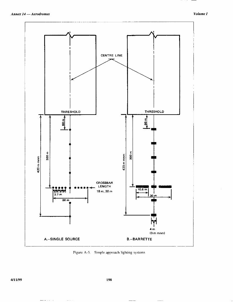
S'TD.ICAO ANNEX l,q VOL I-ENGL 1999 I *18424l,b Ul,D=lO=lCl 877 E
Annex I4 - Aerodromes Volume I
4m
(3 m mnm)
A.-SINGLE SOURCE B.-BARRETTE
Figure A-5. Simple approach lighting systems
4/l 1199 198

STD.ICAO ANNEX l1’4 VOL. I-ENGL L919 D ‘48llLLlLb llL0=lO=lL 7133 W
.i. i I
1 9 P \ ” I c
\
b 1
t

f '[,STD.ICAO ANNEX l,L( VOL I-ENGL I,997 II 11fi4L4lh 0307092 bqT D I
A
Attachment A Annex 14 — Aerodromes
11.3.3 It is recognized that some components of elec-tronic landing aids systems, such as reflectors, antennas,monitors, etc., must be installed above the light plane. Everyeffort should be made to relocate such components outside theboundaries of the light plane. In the case of reflectors andmonitors, this can be done in many instances.
11.3.4 Where an ILS localizer is installed within the lightplane boundaries, it is recognized that the localizer, or screenif used, must extend above the light plane. In such cases theheight of these structures should be held to a minimum andthey should be located as far from the threshold as possible. Ingeneral the rule regarding permissible heights is 15 cm foreach 30 m the structure is located from the threshold. As anexample, if the localizer is located 300 m from the threshold,the screen will be permitted to extend above the plane of theapproach lighting system by 10 × 15 = 150 cm maximum, butpreferably should be kept as low as possible consistent withproper operation of the ILS.
11.3.5 In locating an MLS azimuth antenna the guidancecontained in Annex 10, Volume I, Attachment G to Part Ishould be followed. This material, which also providesguidance on collocating an MLS azimuth antenna with an ILSlocalizer antenna, suggests that the MLS azimuth antenna maybe sited within the light plane boundaries where it is notpossible or practical to locate it beyond the outer end of theapproach lighting for the opposite direction of approach. If theMLS azimuth antenna is located on the extended centre line ofthe runway, it should be as far as possible from the closestlight position to the MLS azimuth antenna in the direction ofthe runway end. Furthermore, the MLS azimuth antenna phasecentre should be at least 0.3 m above the light centre of thelight position closest to the MLS azimuth antenna in thedirection of the runway end. (This could be relaxed to 0.15 mif the site is otherwise free of significant multipath problems.)Compliance with this requirement, which is intended to ensurethat the MLS signal quality is not affected by the approachlighting system, could result in the partial obstruction of thelighting system by the MLS azimuth antenna. To ensure thatthe resulting obstruction does not degrade visual guidancebeyond an acceptable level, the MLS azimuth antenna shouldnot be located closer to the runway end than 300 m and thepreferred location is 25 m beyond the 300 m crossbar (thiswould place the antenna 5 m behind the light position 330 mfrom the runway end). Where an MLS azimuth antenna is solocated, a central part of the 300 m crossbar of the approachlighting system would alone be partially obstructed. Never-theless, it is important to ensure that the unobstructed lights ofthe crossbar remain serviceable all the time.
11.3.6 Objects existing within the boundaries of the lightplane, requiring the light plane to be raised in order to meet thecriteria contained herein, should be removed, lowered orrelocated where this can be accomplished more economicallythan raising the light plane.
11.3.7 In some instances objects may exist which cannotbe removed, lowered or relocated economically. These objects
may be located so close to the threshold that they cannot becleared by the 2 per cent slope. Where such conditions existand no alternative is possible, the 2 per cent slope may beexceeded or a “stair step” resorted to in order to keep theapproach lights above the objects. Such “step” or increasedgradients should be resorted to only when it is impracticable tofollow standard slope criteria, and they should be held to theabsolute minimum. Under this criterion no negative slope ispermitted in the outermost portion of the system.
11.4 Consideration of the effects of reduced lengths
11.4.1 The need for an adequate approach lighting systemto support precision approaches where the pilot is required toacquire visual references prior to landing, cannot be stressedtoo strongly. The safety and regularity of such operations isdependent on this visual acquisition. The height above runwaythreshold at which the pilot decides there are sufficient visualcues to continue the precision approach and land will vary,depending on the type of approach being conducted and otherfactors such as meteorological conditions, ground and air-borne equipment, etc. The required length of approach lightingsystem which will support all the variations of such ap-proaches is 900 m, and this shall always be provided when-ever possible.
11.4.2 However, there are some runway locations whereit is impossible to provide the 900 m length of approachlighting system to support precision approaches.
11.4.3 In such cases, every effort should be made toprovide as much approach lighting system as possible. Theappropriate authority may impose restrictions on operations torunways equipped with reduced lengths of lighting. There aremany factors which determine at what height the pilot musthave decided to continue the approach to land or execute amissed approach. It must be understood that the pilot does notmake an instantaneous judgement upon reaching a specifiedheight. The actual decision to continue the approach andlanding sequence is an accumulative process which is onlyconcluded at the specified height. Unless lights are availableprior to reaching the decision point, the visual assessmentprocess is impaired and the likelihood of missed approacheswill increase substantially. There are many operational con-siderations which must be taken into account by theappropriate authorities in deciding if any restrictions arenecessary to any precision approach and these are detailed inAnnex 6.
12. Priority of installation of visual approachslope indicator systems
12.1 It has been found impracticable to develop guidancematerial that will permit a completely objective analysis to bemade of which runway on an aerodrome should receive first
201 4/11/99

Annex 14 — Aerodromes Volume I
priority for the installation of a visual approach slope indicatorsystem. However, factors that must be considered whenmaking such a decision are:
a) frequency of use;
b) seriousness of the hazard;
c) presence of other visual and non-visual aids;
d) type of aeroplanes using the runway; and
e) frequency and type of adverse weather conditions underwhich the runway will be used.
12.2 With respect to the seriousness of the hazard, theorder given in the application specifications for a visualapproach slope indicator system, 5.3.5.1 b) to e) of Chapter 5may be used as a general guide. These may be summarized as:
a) inadequate visual guidance because of:
1) approaches over water or featureless terrain, orabsence of sufficient extraneous light in the approacharea by night;
2) deceptive surrounding terrain;
b) serious hazard in approach;
c) serious hazard if aeroplanes undershoot or overrun; and
d) unusual turbulence.
12.3 The presence of other visual or non-visual aids is avery important factor. Runways equipped with ILS or MLSwould generally receive the lowest priority for a visualapproach slope indicator system installation. It must beremembered, though, that visual approach slope indicatorsystems are visual approach aids in their own right and cansupplement electronic aids. When serious hazards exist and/ora substantial number of aeroplanes not equipped for ILS orMLS use a runway, priority might be given to installing avisual approach slope indicator on this runway.
12.4 Priority should be given to runways used by turbo-jet aeroplanes.
13. Lighting of unserviceable areas
13.1 Where a temporarily unserviceable area exists, itmay be marked with fixed-red lights. These lights should markthe most potentially dangerous extremities of the area. Aminimum of four such lights should be used, except where thearea is triangular in shape where a minimum of three lightsmay be employed. The number of lights should be increased
when the area is large or of unusual configuration. At least onelight should be installed for each 7.5 m of peripheral distanceof the area. If the lights are directional, they should beorientated so that as far as possible their beams are aligned inthe direction from which aircraft or vehicles will approach.Where aircraft or vehicles will normally approach from severaldirections, consideration should be given to adding extra lightsor using omnidirectional lights to show the area from thesedirections. Unserviceable area lights should be frangible. Theirheight should be sufficiently low to preserve clearance forpropellers and for engine pods of jet aircraft.
14. Intensity control of approachand runway lights
14.1 The conspicuity of a light depends on the impressionreceived of contrast between the light and its background. If alight is to be useful to a pilot by day when on approach, it musthave an intensity of at least 2 000 or 3 000 cd, and in the caseof approach lights an intensity of the order of 20 000 cd isdesirable. In conditions of very bright daylight fog it may notbe possible to provide lights of sufficient intensity to beeffective. On the other hand, in clear weather on a dark night,an intensity of the order of 100 cd for approach lights and50 cd for the runway edge lights may be found suitable. Eventhen, owing to the closer range at which they are viewed,pilots have sometimes complained that the runway edge lightsseemed unduly bright.
14.2 In fog the amount of light scattered is high. At nightthis scattered light increases the brightness of the fog over theapproach area and runway to the extent that little increase inthe visual range of the lights can be obtained by increasingtheir intensity beyond 2 000 or 3 000 cd. In an endeavour toincrease the range at which lights would first be sighted atnight, their intensity must not be raised to an extent that a pilotmight find excessively dazzling at diminished range.
14.3 From the foregoing will be evident the importanceof adjusting the intensity of the lights of an aerodrome lightingsystem according to the prevailing conditions, so as to obtainthe best results without excessive dazzle that would disconcertthe pilot. The appropriate intensity setting on any particularoccasion will depend both on the conditions of backgroundbrightness and the visibility. Detailed guidance material onselecting intensity setting for different conditions is given inthe Aerodrome Design Manual, Part 4.
15. Signal area
A signal area need be provided only when it is intended to usevisual ground signals to communicate with aircraft in flight.Such signals may be needed when the aerodrome does nothave an aerodrome control tower or an aerodrome flight
4/11/99 202

Attachment A Annex 14 — Aerodromes
information service unit, or when the aerodrome is used byaeroplanes not equipped with radio. Visual ground signals mayalso be useful in the case of failure of two-way radiocommunication with aircraft. It should be recognized, how-ever, that the type of information which may be conveyed byvisual ground signals should normally be available in AIPs orNOTAM. The potential need for visual ground signals shouldtherefore be evaluated before deciding to provide a signal area.
16. Rescue and fire fighting services
16.1 Administration
16.1.1 The rescue and fire fighting service at an aero-drome should be under the administrative control of theaerodrome management, which should also be responsible forensuring that the service provided is organized, equipped,staffed, trained and operated in such a manner as to fulfil itsproper functions.
16.1.2 In drawing up the detailed plan for the conduct ofsearch and rescue operations in accordance with 4.2.1 ofAnnex 12, the aerodrome management should co-ordinate itsplans with the relevant rescue co-ordination centres to ensurethat the respective limits of their responsibilities for an aircraftaccident within the vicinity of an aerodrome are clearlydelineated.
16.1.3 Co-ordination between the rescue and fire fightingservice at an aerodrome and public protective agencies, suchas local fire brigade, police force, coast guard and hospitals,should be achieved by prior agreement for assistance indealing with an aircraft accident.
16.1.4 A grid map of the aerodrome and its immediatevicinity should be provided for the use of the aerodrome ser-vices concerned. Information concerning topography, accessroads and location of water supplies should be indicated. Thismap should be conspicuously posted in the control tower andfire station, and available on the rescue and fire fightingvehicles and such other supporting vehicles required torespond to an aircraft accident or incident. Copies should alsobe distributed to public protective agencies as desirable.
16.1.5 Co-ordinated instructions should be drawn updetailing the responsibilities of all concerned and the action tobe taken in dealing with emergencies. The appropriate auth-ority should ensure that such instructions are promulgated andobserved.
16.2 Training
The training curriculum should include initial and recurrentinstruction in at least the following areas:
a) airport familiarization;
b) aircraft familiarization;
c) rescue and fire fighting personnel safety;
d) emergency communications systems on the aerodrome,including aircraft fire related alarms;
e) use of the fire hoses, nozzles, turrets and other ap-pliances required for compliance with Chapter 9, 9.2;
f) application of the types of extinguishing agents requiredfor compliance with Chapter 9, 9.2;
g) emergency aircraft evacuation assistance;
h) fire fighting operations;
i) adaptation and use of structural rescue and fire fightingequipment for aircraft rescue and fire fighting;
j) dangerous goods;
k) familiarization with fire fighters’ duties under the aero-drome emergency plan; and
l) protective clothing and respiratory protection.
16.3 Level of protection to be provided
16.3.1 In accordance with Chapter 9, 9.2 aerodromesshould be categorized for rescue and fire fighting purposes andthe level of protection provided should be appropriate to theaerodrome category.
16.3.2 However, Chapter 9, 9.2.2 permits a lower level ofprotection to be provided for a limited period where thenumber of movements of the aeroplanes in the highestcategory normally using the aerodrome is less than 700 in thebusiest consecutive three months. It is important to note thatthe concession included in 9.2.2 a) is applicable only wherethere is a wide range of difference between the dimensions ofthe aeroplanes included in reaching 700 movements.
16.4 Rescue equipment for difficult environments
16.4.1 Suitable rescue equipment and services should beavailable at an aerodrome where the area to be covered by theservice includes water, swampy areas or other difficultenvironment that cannot be fully served by conventionalwheeled vehicles. This is particularly important where a sig-nificant portion of approach/departure operations takes placeover these areas.
16.4.2 The rescue equipment should be carried on boatsor other vehicles such as helicopters and amphibious or air
203 4/11/99

Annex 14 — Aerodromes Volume I
cushion vehicles, capable of operating in the area concerned.The vehicles should be so located that they can be brought intoaction quickly to respond to the areas covered by the service.
16.4.3 At an aerodrome bordering the water, the boats orother vehicles should preferably be located on the aerodrome,and convenient launching or docking sites provided. If thesevehicles are located off the aerodrome, they should preferablybe under the control of the aerodrome rescue and fire fightingservice or, if this is not practicable, under the control ofanother competent public or private organization working inclose co-ordination with the aerodrome rescue and fire fightingservice (such as police, military services, harbour patrol orcoast guard).
16.4.4 Boats or other vehicles should have as high aspeed as practicable so as to reach an accident site in minimumtime. To reduce the possibility of injury during rescue oper-ations, water jet-driven boats are preferred to water propeller-driven boats unless the propellers of the latter boats are ducted.Should the water areas to be covered by the service be frozenfor a signficant period of the year, the equipment should beselected accordingly. Vehicles used in this service should beequipped with life rafts and life preservers related to therequirements of the larger aircraft normally using theaerodrome, with two-way radio communication, and withfloodlights for night operations. If aircraft operations duringperiods of low visibility are expected, it may be necessary toprovide guidance for the responding emergency vehicles.
16.4.5 The personnel designated to operate the equipmentshould be adequately trained and drilled for rescue services inthe appropriate environment.
16.5 Facilities
16.5.1 The provision of special telephone, two-way radiocommunication and general alarm systems for the rescue andfire fighting service is desirable to ensure the dependabletransmission of essential emergency and routine information.Consistent with the individual requirements of each aero-drome, these facilities serve the following purposes:
a) direct communication between the activating authorityand the aerodrome fire station in order to ensure theprompt alerting and dispatch of rescue and fire fightingvehicles and personnel in the event of an aircraftaccident or incident;
b) emergency signals to ensure the immediate summoningof designated personnel not on standby duty;
c) as necessary, summoning essential related services on oroff the aerodrome; and
d) maintaining communication by means of two-way radiowith the rescue and fire fighting vehicles in attendanceat an aircraft accident or incident.
16.5.2 The availability of ambulance and medicalfacilities for the removal and after-care of casualties arisingfrom an aircraft accident should receive the careful consider-ation of the appropriate authority and should form part of theover-all emergency plan established to deal with suchemergencies.
17. Operators of vehicles
17.1 The authorities responsible for the operation ofvehicles on the movement area should ensure that the oper-ators are properly qualified. This may include, as appropriateto the driver’s function, knowledge of:
a) the geography of the aerodrome;
b) aerodrome signs, markings and lights;
c) radiotelephone operating procedures;
d) terms and phrases used in aerodrome control includingthe ICAO spelling alphabet;
e) rules of air traffic services as they relate to groundoperations;
f) airport rules and procedures; and
g) specialist functions as required, for example, in rescueand fire fighting.
17.2 The operator should be able to demonstrate com-petency, as appropriate, in:
a) the operation or use of vehicle transmit/receiveequipment;
b) understanding and complying with air traffic control andlocal procedures;
c) vehicle navigation on the aerodrome; and
d) special skills required for the particular function.
In addition, as required for any specialist function, the operatorshould be the holder of a State driver’s licence, a State radiooperator’s licence or other licences.
17.3 The above should be applied as is appropriate tothe function to be performed by the operator and it is notnecessary that all operators be trained to the same level, forexample, operators whose functions are restricted to theapron.
17.4 If special procedures apply for operations in lowvisibility conditions, it is desirable to verify an operator’sknowledge of the procedures through periodic checks.
4/11/99 204

Attachment A Annex 14 — Aerodromes
18. The ACN-PCN method of reportingpavement strength
18.1 Overload operations
18.1.1 Overloading of pavements can result either fromloads too large, or from a substantially increased applicationrate, or both. Loads larger than the defined (design orevaluation) load shorten the design life, whilst smaller loadsextend it. With the exception of massive overloading,pavements in their structural behaviour are not subject to aparticular limiting load above which they suddenly orcatastrophically fail. Behaviour is such that a pavement cansustain a definable load for an expected number of repetitionsduring its design life. As a result, occasional minor over-loading is acceptable, when expedient, with only limited lossin pavement life expectancy and relatively small accelerationof pavement deterioration. For those operations in whichmagnitude of overload and/or the frequency of use do notjustify a detailed analysis, the following criteria are suggested:
a) for flexible pavements, occasional movements byaircraft with ACN not exceeding 10 per cent above thereported PCN should not adversely affect the pavement;
b) for rigid or composite pavements, in which a rigidpavement layer provides a primary element of thestructure, occasional movements by aircraft with ACN
not exceeding 5 per cent above the reported PCN shouldnot adversely affect the pavement;
c) if the pavement structure is unknown, the 5 per centlimitation should apply; and
d) the annual number of overload movements should notexceed approximately 5 per cent of the total annualaircraft movements.
18.1.2 Such overload movements should not normally bepermitted on pavements exhibiting signs of distress or failure.Furthermore, overloading should be avoided during anyperiods of thaw following frost penetration, or when thestrength of the pavement or its subgrade could be weakened bywater. Where overload operations are conducted, the appro-priate authority should review the relevant pavement conditionregularly, and should also review the criteria for overloadoperations periodically since excessive repetition of overloadscan cause severe shortening of pavement life or require majorrehabilitation of pavement.
18.2 ACNs for several aircraft types
For convenience, several aircraft types currently in use havebeen evaluated on rigid and flexible pavements founded on thefour subgrade strength categories in Chapter 2, 2.6.6 b) and theresults tabulated in the Aerodrome Design Manual, Part 3.
205 4/11/99

4fllf99
‘STP.ICAO ANNEX I,4 VOL I-ENGL l,SY=l Hi ‘iP14L41L 0107098 Ob8 E
ATTACHMENT B. OBSTACLE LIMITATION SUFWACES
Figure B-l
206 ANNEX 14 - VOLUME I

LIMITED INDEX OF SIGNIFICANT SUBJECTSINCLUDED IN ANNEX 14, VOLUME I
AERODROME OPERATION*
apron management service 9.6bird hazard reduction 9.5denoting closed areas 7.1denoting unserviceable areas 7.4disabled aircraft removal 9.3emergency planning 9.1ground servicing of aircraft 9.7light intensity control A-14lighting of unserviceable areas A-13maintenance 9.4marking of vehicles or mobile objects 6.1.6;
6.2.2; 6.2.14measuring runway braking action/friction A-6; A-7mobile obstacles on runway strips 3.3.7monitoring visual aids 8.3overload operations A-18.1reporting aerodrome data 2rescue and fire fighting 9.2; A-16secondary power supply 8.1
APRON
clearance of debris 9.4.3clearance of snow, ice, etc. 9.4.11; 9.4.12definition 1.1physical characteristics 3.12isolated aircraft parking position 3.13lighting 5.3.21reporting requirements 2.5.1 d)safety lines 5.2.13
APRON MANAGEMENT SERVICE
definition 1.1provision 9.6
CLEARWAY
accountability as runway length 3.1.8definition 1.1frangibility 8.7.1 b); 8.7.2 c)general A-2physical characteristics 3.5reporting requirements 2.5.1 f)
*Those specifications which relate to the daily operation of an aerodrome ascompared with those which relate to its design or facilities to be provided.
DE-ICING/ANTI-ICING FACILITY
definition 1.1lighting 5.3.19location 3.14.2marking 5.2.10.2
DECLARED DISTANCES
calculation A-3definition 1.1reporting requirements 2.8
DISABLED AIRCRAFT REMOVAL
capability 9.3reporting requirements 2.10
DISPLACED THRESHOLD
definition 1.1lights 5.3.10.1; 5.3.10.3location A-10.2marking 5.2.4.9; 5.2.4.10
FRANGIBILITY
definition of frangible object 1.1elevated approach lights 5.3.1.3.; 5.3.1.4markers 5.5.1objects on operational areas 8.7objects on runway strips 3.3.7other elevated lights 5.3.1.6PAPI and APAPI 5.3.5.27signs 5.4.1.3T-VASIS and AT-VASIS 5.3.5.16
GRADING
radio altimeter operating area 3.7.4runway end safety areas 3.4.5runway strips 3.3.8-3.3.11strip for precision approach runways A-8.3taxiway strips 3.10.4
HELIPORT
definition 1.1specifications See Annex 14, Volume II
ANNEX 14 — VOLUME I 207 4/11/991/11/01
No. 4
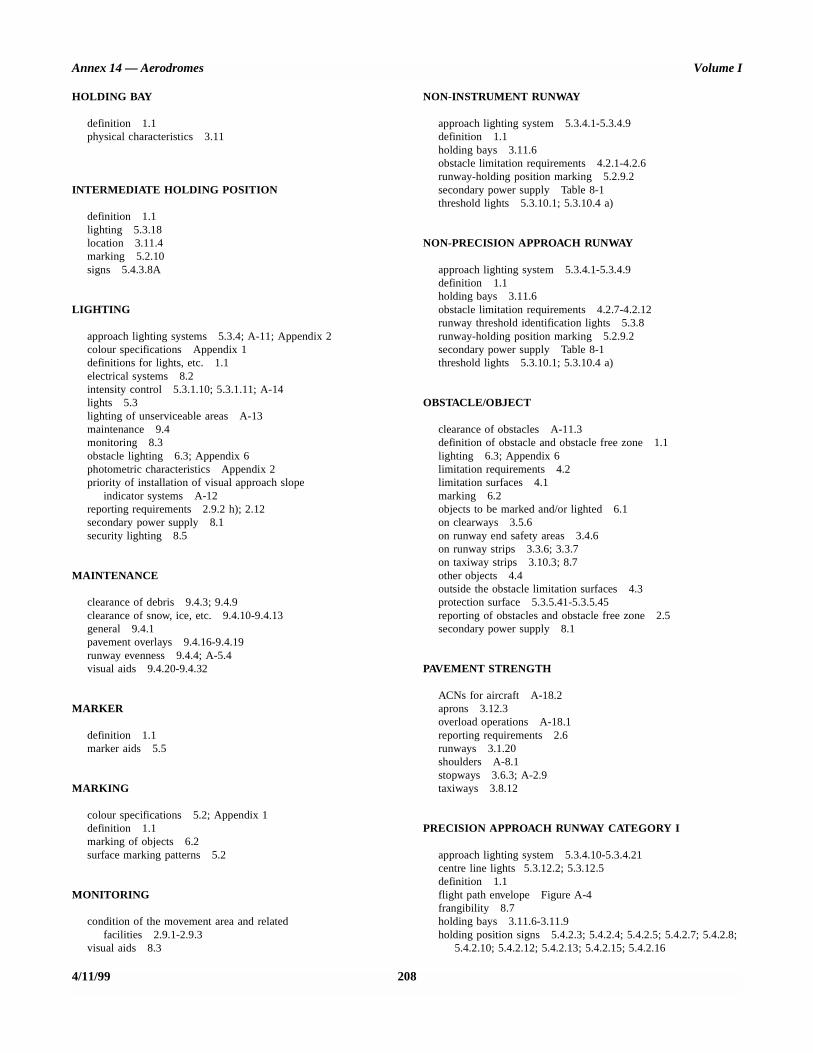
Annex 14 — Aerodromes Volume I
HOLDING BAY
definition 1.1physical characteristics 3.11
INTERMEDIATE HOLDING POSITION
definition 1.1lighting 5.3.18location 3.11.4marking 5.2.10signs 5.4.3.8A
LIGHTING
approach lighting systems 5.3.4; A-11; Appendix 2colour specifications Appendix 1definitions for lights, etc. 1.1electrical systems 8.2intensity control 5.3.1.10; 5.3.1.11; A-14lights 5.3lighting of unserviceable areas A-13maintenance 9.4monitoring 8.3obstacle lighting 6.3; Appendix 6photometric characteristics Appendix 2priority of installation of visual approach slope
indicator systems A-12reporting requirements 2.9.2 h); 2.12secondary power supply 8.1security lighting 8.5
MAINTENANCE
clearance of debris 9.4.3; 9.4.9clearance of snow, ice, etc. 9.4.10-9.4.13general 9.4.1pavement overlays 9.4.16-9.4.19runway evenness 9.4.4; A-5.4visual aids 9.4.20-9.4.32
MARKER
definition 1.1marker aids 5.5
MARKING
colour specifications 5.2; Appendix 1definition 1.1marking of objects 6.2surface marking patterns 5.2
MONITORING
condition of the movement area and relatedfacilities 2.9.1-2.9.3
visual aids 8.3
NON-INSTRUMENT RUNWAY
approach lighting system 5.3.4.1-5.3.4.9definition 1.1holding bays 3.11.6obstacle limitation requirements 4.2.1-4.2.6runway-holding position marking 5.2.9.2secondary power supply Table 8-1threshold lights 5.3.10.1; 5.3.10.4 a)
NON-PRECISION APPROACH RUNWAY
approach lighting system 5.3.4.1-5.3.4.9definition 1.1holding bays 3.11.6obstacle limitation requirements 4.2.7-4.2.12runway threshold identification lights 5.3.8runway-holding position marking 5.2.9.2secondary power supply Table 8-1threshold lights 5.3.10.1; 5.3.10.4 a)
OBSTACLE/OBJECT
clearance of obstacles A-11.3definition of obstacle and obstacle free zone 1.1lighting 6.3; Appendix 6limitation requirements 4.2limitation surfaces 4.1marking 6.2objects to be marked and/or lighted 6.1on clearways 3.5.6on runway end safety areas 3.4.6on runway strips 3.3.6; 3.3.7on taxiway strips 3.10.3; 8.7other objects 4.4outside the obstacle limitation surfaces 4.3protection surface 5.3.5.41-5.3.5.45reporting of obstacles and obstacle free zone 2.5secondary power supply 8.1
PAVEMENT STRENGTH
ACNs for aircraft A-18.2aprons 3.12.3overload operations A-18.1reporting requirements 2.6runways 3.1.20shoulders A-8.1stopways 3.6.3; A-2.9taxiways 3.8.12
PRECISION APPROACH RUNWAY CATEGORY I
approach lighting system 5.3.4.10-5.3.4.21centre line lights 5.3.12.2; 5.3.12.5definition 1.1flight path envelope Figure A-4frangibility 8.7holding bays 3.11.6-3.11.9holding position signs 5.4.2.3; 5.4.2.4; 5.4.2.5; 5.4.2.7; 5.4.2.8;
5.4.2.10; 5.4.2.12; 5.4.2.13; 5.4.2.15; 5.4.2.16
4/11/99 208

Index Annex 14 — Aerodromes
maintenance of visual aids 9.4.20; 9.4.29objects on strips 3.3.7obstacle limitation requirements 4.2.13; 4.2.14;
4.2.16-4.2.21runway light characteristics Appendix 2runway-holding position marking 5.2.9.3secondary power supply Table 8-1threshold lights 5.3.10.4 b)
PRECISION APPROACH RUNWAYSCATEGORIES II AND III
approach lighting system 5.3.4.22-5.3.4.39definition 1.1flight path envelopes Figure A-4frangibility 8.7holding bays 3.11.6-3.11.9holding position signs 5.4.2.3; 5.4.2.4; 5.4.2.5; 5.4.2.7; 5.4.2.8;
5.4.2.10; 5.4.2.12; 5.4.2.13; 5.4.2.15; 5.4.2.16maintenance of visual aids 9.4.20-9.4.26objects on strips 3.3.7obstacle limitation requirements 4.2.15-4.2.21runway centre line lights 5.3.12.1; 5.3.12.5runway end lights 5.3.11.3runway light characteristics Appendix 2runway-holding position marking 5.2.9.3secondary power supply Table 8-1stop bars 5.3.17taxiway centre line lights 5.3.15taxiway light characteristics Appendix 2threshold lights 5.3.10.4 c)touchdown zone lights 5.3.13.1
RESCUE AND FIRE FIGHTING
communication and alerting system 9.2.27; 9.2.28emergency access roads 9.2.22-9.2.24extinguishing agents 9.2.7-9.2.17fire stations 9.2.25; 9.2.26general 9.2 (Introductory Note)level of protection 9.2.2-9.2.6; A-16.3personnel 9.2.31; 9.2.32reporting requirements 2.11rescue equipment 9.2.18; 9.2.29response time 9.2.19-9.2.21vehicles 9.2.29
RUNWAY
clearance of debris 9.4.3clearance of snow, ice, etc. 9.4.10; A-6closed runway marking 7.1definition 1.1lights 5.3.7-5.3.13; Appendix 2markers 5.5.2; 5.5.4marking 5.2.2.-5.2.7number, siting and orientation A-1pavement overlays 9.4.16-9.4.19physical characteristics 3.1reporting requirements 2.3.2; 2.5.1. a); 2.8;
2.9.2; 2.9.4-2.9.11; A-6; A-7runway surface evenness A-5
shoulders 3.2slopes 3.1.12-3.1.19; A-4strips 2.5.1 b); 3.3; 8.7.1 a); 8.7.4; 8.7.6
RUNWAY END SAFETY AREA
definition 1.1frangibility 8.7.1 a); 8.7.2 b)general A-9physical characteristics 3.4reporting requirements 2.5.1 b)
RUNWAY-HOLDING POSITION
definition 1.1location 3.11.2; 3.11.3; 3.11.9marking 5.2.9runway guard lights 5.3.19signs 5.4.2.2-5.4.2.5; 5.4.2.7; 5.4.2.8;
5.4.2.10; 5.4.2.12; 5.4.2.13; 5.4.2.15; 5.4.2.16
stop bars 5.3.17
RUNWAY MEANT FOR TAKE-OFF
climb surface 4.1.25-4.1.29frangibility 8.7maintenance of visual aids 9.4.20; 9.4.30; 9.4.31obstacle limitation requirements 4.2.22-4.2.27runway lighting 5.3.9.2; 5.3.12.3; 5.3.12.4secondary power supply Table 8-1taxiway lighting 5.3.15; 5.3.16
RUNWAY SURFACE FRICTION CHARACTERISTICS
maintenance 9.4.3-9.4.7; 9.4.9; 9.4.12reporting requirements 2.9runway design 3.1.22runway surface friction 2.9.6; 2.9.9snow- and ice-covered paved surfaces – general A-6wet runways – general A-7
SECURITY
aerodrome emergency planning 9.1.2 (Note)airport design 8.6fencing 8.4isolated aircraft parking position 3.13lighting 8.5
STOPWAY
accountability as runway length 3.1.8definition 1.1general A-2lights 5.3.14; Appendix 2markers 5.5.3physical characteristics 3.6reporting requirements 2.5.1. b)
209 4/11/99

Annex 14 — Aerodromes Volume I
TAXIWAY
closed taxiway marking 7.1definition 1.1lights 5.3.15; 5.3.16; Appendix 2markers 5.5.5; 5.5.6; 5.5.7marking 5.2.8; 5.2.10; 7.2physical characteristics 3.8removal of contaminants 9.4.9; 9.4.11; 9.4.13reporting requirements 2.5.1 c)
shoulders 3.9strips 3.10; 8.7.1 a); 8.7.4
VISUAL APPROACH SLOPE INDICATOR SYSTEMS
characteristics 5.3.5priority of installation A-12reporting requirements 2.12secondary power supply 8.1
— END —
4/11/99 210
8/9/00
Transmittal Note
SUPPLEMENT TO
ANNEX 14, VOLUME I �
AERODROME DESIGN AND OPERATIONS
(Third Edition)
1. The attached Supplement supersedes all previous Supplements to Annex 14, Volume I, and includesdifferences notified by Contracting States up to 11 August 2000.
2. This Supplement should be inserted at the end of Annex 14, Volume I, Third Edition. Additionaldifferences and revised comments received from Contracting States will be issued at intervals asamendments to this Supplement.

SUPPLEMENT TO ANNEX 14, VOLUME I — THIRD EDITION
AERODROME DESIGN AND OPERATIONS
Differences between the national regulations and practices of States and thecorresponding International Standards contained in Annex 14, Volume I, asnotified to ICAO in accordance with Article 38 of the Convention onInternational Civil Aviation and the Council’s resolution of 21 November 1950.
SEPTEMBER 2000
I N T E R N A T I O N A L C I V I L A V I A T I O N O R G A N I Z A T I O N

(ii) SUPPLEMENT TO ANNEX 14, VOLUME I (THIRD EDITION)
8/9/00
RECORD OF AMENDMENTS TO SUPPLEMENT
No. Date Entered by No. Date Entered by
RECORD OF AMENDMENTS TO ANNEX 14, VOLUME I (THIRD EDITION)
No.
Date ofadoption orapproval
Dateapplicable No.
Date ofadoption orapproval Date applicable

SUPPLEMENT TO ANNEX 14, VOLUME I (THIRD EDITION) (iii)
8/9/00
1. Contracting States which have notified ICAO of differences
The Contracting States listed below have notified ICAO of differences which exist between their national regulations andpractices and the International Standards and Recommended Practices of Annex 14, Volume I, Third Edition, or havecommented on implementation.
The page numbers shown for each State and the dates of publication of those pages correspond to the actual pages in thisSupplement.
Pages in Date ofState Supplement publication
Austria 1 8/9/00Belgium 1-2 8/9/00Canada 1-2 8/9/00China (Hong Kong SAR) 1-2 8/9/00Denmark 1 8/9/00Finland 1-3 8/9/00France 1-6 8/9/00Germany 1 8/9/00Japan 1 8/9/00Kyrgyzstan 1 8/9/00Netherlands 1 8/9/00New Zealand 1-2 8/9/00Norway 1 8/9/00Portugal 1 8/9/00Russian Federation 1-2 8/9/00South Africa 1 8/9/00Spain 1 8/9/00Sweden 1 8/9/00Switzerland 1 8/9/00Uganda 1 8/9/00United Kingdom 1-6 8/9/00United States 1-13 8/9/00
2. Contracting States which have notified ICAO that no differences exist
ColombiaEgyptGeorgiaGhana
IrelandMalaysia MonacoNamibia
PeruSri LankaUnited Republic of Tanzania

(iv) SUPPLEMENT TO ANNEX 14, VOLUME I (THIRD EDITION)
8/9/00
3. Contracting States from which no information has been received
AfghanistanAlbaniaAlgeriaAngolaAntigua and BarbudaArgentinaArmeniaAustraliaAzerbaijanBahamasBahrainBangladeshBarbadosBelarusBelizeBeninBhutanBoliviaBosnia and HerzegovinaBotswanaBrazilBrunei DarussalamBulgariaBurkina FasoBurundiCambodiaCameroonCape VerdeCentral African RepublicChadChileChinaComorosCongoCook IslandsCosta RicaCôte d’IvoireCroatiaCubaCyprusCzech RepublicDemocratic People’s Republic of
KoreaDemocratic Republic of
the CongoDjiboutiDominican RepublicEcuadorEl SalvadorEquatorial GuineaEritreaEstonia
EthiopiaFijiGabonGambiaGreece GrenadaGuatemalaGuineaGuinea-BissauGuyanaHaitiHondurasHungaryIcelandIndiaIndonesiaIran (Islamic Republic of)IraqIsraelItalyJamaicaJordanKazakhstanKenyaKiribatiKuwaitLao People’s Democratic RepublicLatviaLebanonLesothoLiberiaLibyan Arab JamahiriyaLithuaniaLuxembourgMadagascarMalawiMaldivesMaliMaltaMarshall IslandsMauritaniaMauritiusMexicoMicronesia (Federated States of)MongoliaMoroccoMozambiqueMyanmarNauruNepalNicaraguaNiger
NigeriaOmanPakistanPalauPanamaPapua New GuineaParaguayPhilippinesPolandQatarRepublic of KoreaRepublic of MoldovaRomaniaRwandaSaint LuciaSaint Vincent and the GrenadinesSamoaSan MarinoSao Tome and PrincipeSaudi ArabiaSenegalSeychellesSierra LeoneSingaporeSlovakiaSloveniaSolomon IslandsSomaliaSudanSurinameSwazilandSyrian Arab RepublicTajikistanThailandThe former Yugoslav Republic
of MacedoniaTogoTongaTrinidad and TobagoTunisiaTurkeyTurkmenistanUkraineUnited Arab EmiratesUruguayUzbekistanVanuatuVenezuelaViet NamYemenZambiaZimbabwe
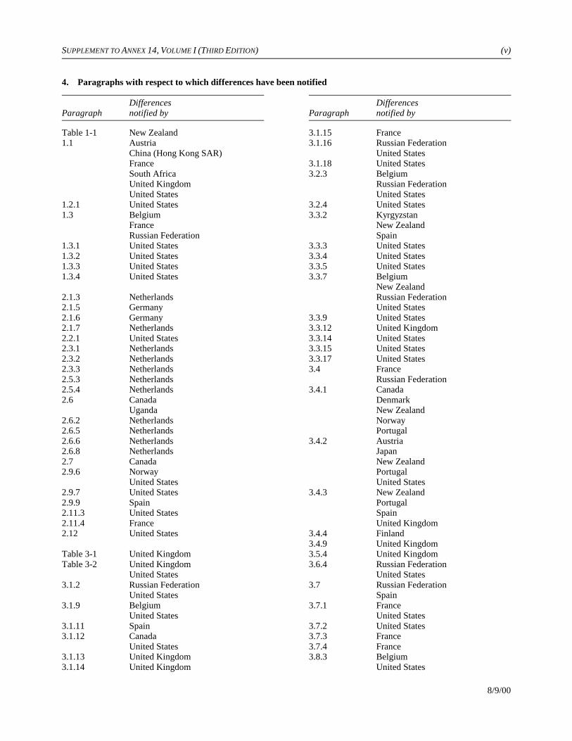
SUPPLEMENT TO ANNEX 14, VOLUME I (THIRD EDITION) (v)
8/9/00
4. Paragraphs with respect to which differences have been notified
Differences DifferencesParagraph notified by Paragraph notified by
Table 1-1 New Zealand1.1 Austria
China (Hong Kong SAR)FranceSouth AfricaUnited KingdomUnited States
1.2.1 United States1.3 Belgium
FranceRussian Federation
1.3.1 United States1.3.2 United States1.3.3 United States1.3.4 United States
2.1.3 Netherlands2.1.5 Germany2.1.6 Germany2.1.7 Netherlands2.2.1 United States2.3.1 Netherlands2.3.2 Netherlands2.3.3 Netherlands2.5.3 Netherlands2.5.4 Netherlands2.6 Canada
Uganda2.6.2 Netherlands2.6.5 Netherlands2.6.6 Netherlands2.6.8 Netherlands2.7 Canada2.9.6 Norway
United States2.9.7 United States2.9.9 Spain2.11.3 United States2.11.4 France2.12 United States
Table 3-1 United KingdomTable 3-2 United Kingdom
United States3.1.2 Russian Federation
United States3.1.9 Belgium
United States3.1.11 Spain3.1.12 Canada
United States3.1.13 United Kingdom3.1.14 United Kingdom
3.1.15 France3.1.16 Russian Federation
United States3.1.18 United States3.2.3 Belgium
Russian FederationUnited States
3.2.4 United States3.3.2 Kyrgyzstan
New ZealandSpain
3.3.3 United States3.3.4 United States3.3.5 United States3.3.7 Belgium
New ZealandRussian FederationUnited States
3.3.9 United States3.3.12 United Kingdom3.3.14 United States3.3.15 United States3.3.17 United States3.4 France
Russian Federation3.4.1 Canada
DenmarkNew ZealandNorwayPortugal
3.4.2 AustriaJapanNew ZealandPortugalUnited States
3.4.3 New ZealandPortugalSpainUnited Kingdom
3.4.4 Finland3.4.9 United Kingdom3.5.4 United Kingdom3.6.4 Russian Federation
United States3.7 Russian Federation
Spain3.7.1 France
United States3.7.2 United States3.7.3 France3.7.4 France3.8.3 Belgium
United States
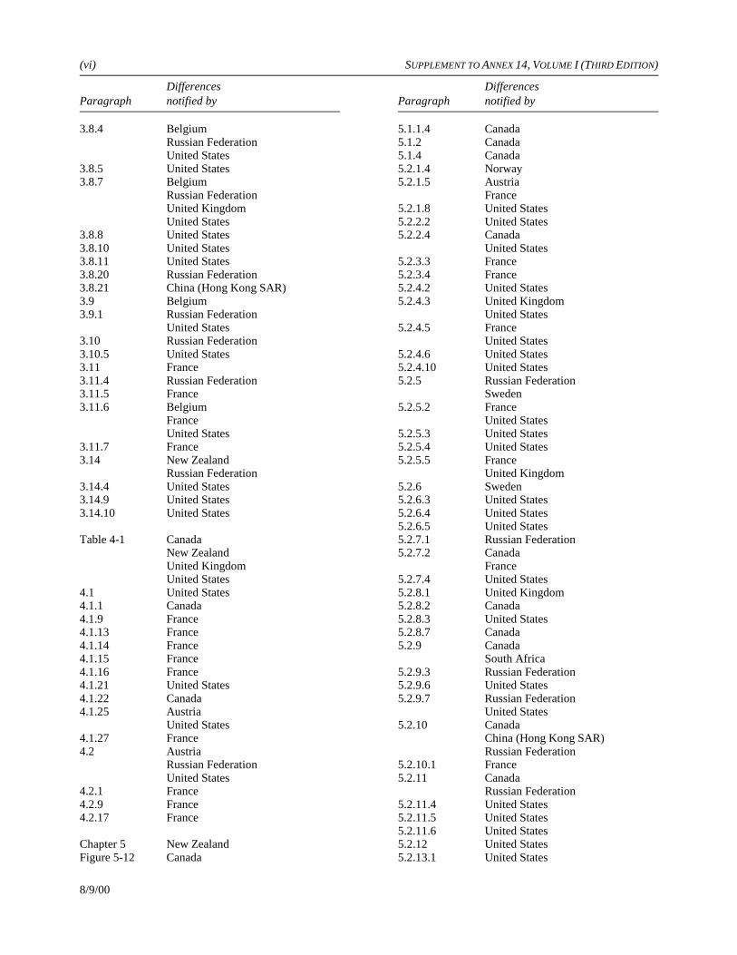
(vi) SUPPLEMENT TO ANNEX 14, VOLUME I (THIRD EDITION)
Differences DifferencesParagraph notified by Paragraph notified by
8/9/00
3.8.4 BelgiumRussian FederationUnited States
3.8.5 United States3.8.7 Belgium
Russian FederationUnited KingdomUnited States
3.8.8 United States3.8.10 United States3.8.11 United States3.8.20 Russian Federation3.8.21 China (Hong Kong SAR)3.9 Belgium3.9.1 Russian Federation
United States3.10 Russian Federation3.10.5 United States3.11 France3.11.4 Russian Federation3.11.5 France3.11.6 Belgium
FranceUnited States
3.11.7 France3.14 New Zealand
Russian Federation3.14.4 United States3.14.9 United States3.14.10 United States
Table 4-1 CanadaNew ZealandUnited KingdomUnited States
4.1 United States4.1.1 Canada4.1.9 France4.1.13 France4.1.14 France4.1.15 France4.1.16 France4.1.21 United States4.1.22 Canada4.1.25 Austria
United States4.1.27 France4.2 Austria
Russian FederationUnited States
4.2.1 France4.2.9 France4.2.17 France
Chapter 5 New ZealandFigure 5-12 Canada
5.1.1.4 Canada5.1.2 Canada5.1.4 Canada5.2.1.4 Norway5.2.1.5 Austria
France5.2.1.8 United States5.2.2.2 United States5.2.2.4 Canada
United States5.2.3.3 France5.2.3.4 France5.2.4.2 United States5.2.4.3 United Kingdom
United States5.2.4.5 France
United States5.2.4.6 United States5.2.4.10 United States5.2.5 Russian Federation
Sweden5.2.5.2 France
United States5.2.5.3 United States5.2.5.4 United States5.2.5.5 France
United Kingdom5.2.6 Sweden5.2.6.3 United States5.2.6.4 United States5.2.6.5 United States5.2.7.1 Russian Federation5.2.7.2 Canada
France5.2.7.4 United States5.2.8.1 United Kingdom5.2.8.2 Canada5.2.8.3 United States5.2.8.7 Canada5.2.9 Canada
South Africa5.2.9.3 Russian Federation5.2.9.6 United States5.2.9.7 Russian Federation
United States5.2.10 Canada
China (Hong Kong SAR)Russian Federation
5.2.10.1 France5.2.11 Canada
Russian Federation5.2.11.4 United States5.2.11.5 United States5.2.11.6 United States5.2.12 United States5.2.13.1 United States

SUPPLEMENT TO ANNEX 14, VOLUME I (THIRD EDITION) (vii)
Differences DifferencesParagraph notified by Paragraph notified by
8/9/00
5.2.14 Russian Federation5.2.14.1 United States5.2.15 Spain
United Kingdom5.2.16.1 Sweden5.3.1.1 United States5.3.1.2 United States5.3.1.3 United States5.3.1.4 United States5.3.2.1 United States5.3.2.2 United States5.3.2.3 United States5.3.3 Canada5.3.3.1 United States5.3.3.3 Finland
United States5.3.3.6 United States5.3.3.8 United States5.3.3.12 France5.3.4.1 Finland
FranceUnited States
5.3.4.2 CanadaUnited States
5.3.4.10 BelgiumUnited States
5.3.4.11 United States5.3.4.12 United States5.3.4.13 United States5.3.4.14 United States5.3.4.15 Canada
United KingdomUnited States
5.3.4.16 United States5.3.4.17 United States5.3.4.18 United States5.3.4.19 United States5.3.4.22 Belgium
United KingdomUnited States
5.3.4.23 Belgium5.3.4.24 Belgium
United Kingdom5.3.4.30 United Kingdom5.3.4.32 United Kingdom5.3.4.33 United Kingdom5.3.4.35 United States5.3.5 Spain
Switzerland5.3.5.1 Canada
FinlandFranceUnited States
5.3.5.2 United States5.3.5.3 United States5.3.5.4 United States
5.3.5.27 United States5.3.5.42 Japan
United KingdomUnited States
5.3.6 Canada5.3.7 Canada5.3.8 Canada5.3.8.4 United States5.3.9.7 Canada5.3.10.1 Norway5.3.10.3 Canada5.3.12.2 United Kingdom5.3.12.3 France5.3.12.4 United Kingdom5.3.13.2 United States5.3.14 Japan
United States5.3.14.3 Canada5.3.15.1 France
United KingdomUnited States
5.3.15.2 FranceUnited States
5.3.15.3 France5.3.15.4 United States5.3.15.7 United Kingdom
United States5.3.15.10 United States5.3.15.11 United Kingdom5.3.15.13 United Kingdom5.3.15.17 United Kingdom5.3.15.18 United Kingdom5.3.16.2 France
United States5.3.16.6 United Kingdom5.3.17.1 France
United States5.3.17.2 France
United States5.3.17.3 France
United States5.3.17.4 United States5.3.17.5 United States5.3.17.6 United States5.3.17.9 United States5.3.17.10 Austria
SpainUnited States
5.3.17.14 BelgiumFrance
5.3.18 France5.3.18.1 Finland
United States5.3.18.2 United States5.3.19 United Kingdom5.3.20.1 Finland
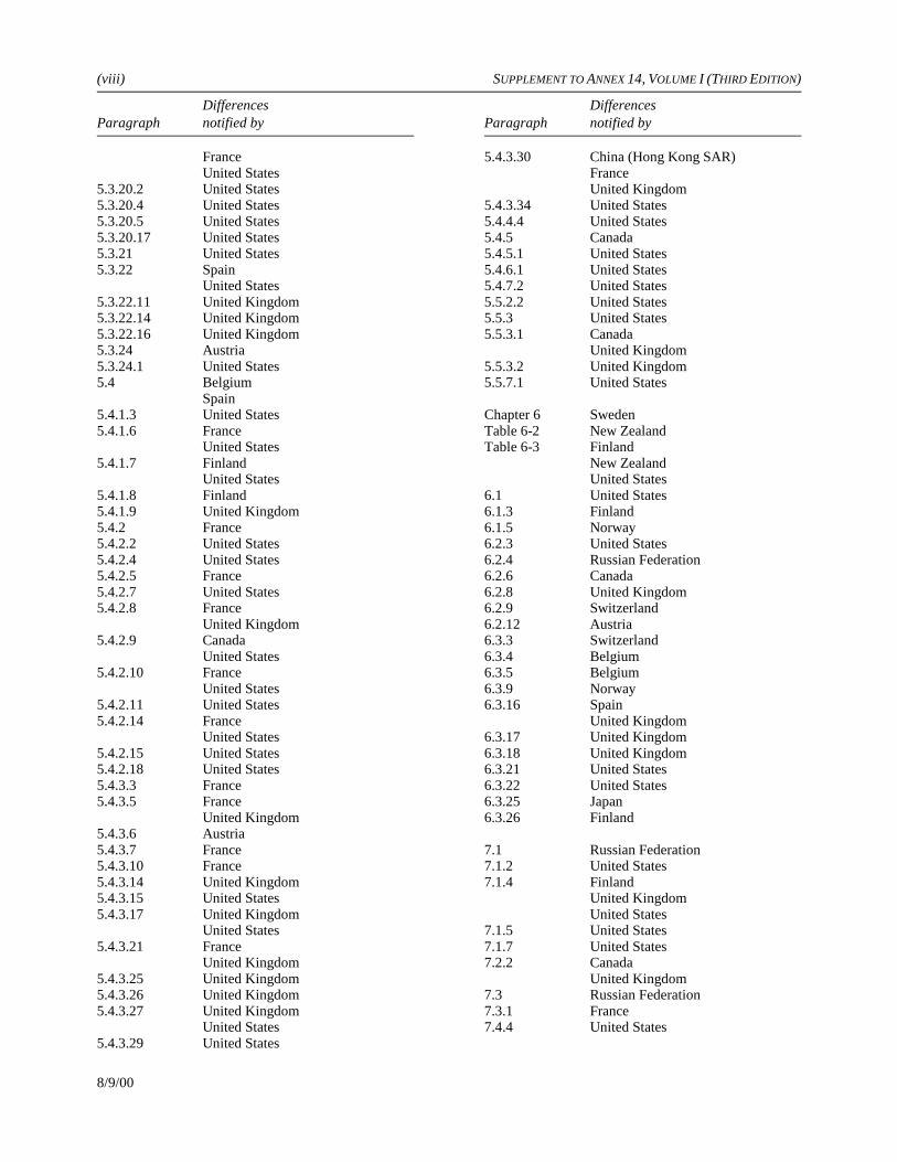
(viii) SUPPLEMENT TO ANNEX 14, VOLUME I (THIRD EDITION)
Differences DifferencesParagraph notified by Paragraph notified by
8/9/00
FranceUnited States
5.3.20.2 United States5.3.20.4 United States5.3.20.5 United States5.3.20.17 United States5.3.21 United States5.3.22 Spain
United States5.3.22.11 United Kingdom5.3.22.14 United Kingdom5.3.22.16 United Kingdom5.3.24 Austria5.3.24.1 United States5.4 Belgium
Spain5.4.1.3 United States5.4.1.6 France
United States5.4.1.7 Finland
United States5.4.1.8 Finland5.4.1.9 United Kingdom5.4.2 France5.4.2.2 United States5.4.2.4 United States5.4.2.5 France5.4.2.7 United States5.4.2.8 France
United Kingdom5.4.2.9 Canada
United States5.4.2.10 France
United States5.4.2.11 United States5.4.2.14 France
United States5.4.2.15 United States5.4.2.18 United States5.4.3.3 France5.4.3.5 France
United Kingdom5.4.3.6 Austria5.4.3.7 France5.4.3.10 France5.4.3.14 United Kingdom5.4.3.15 United States5.4.3.17 United Kingdom
United States5.4.3.21 France
United Kingdom5.4.3.25 United Kingdom5.4.3.26 United Kingdom5.4.3.27 United Kingdom
United States5.4.3.29 United States
5.4.3.30 China (Hong Kong SAR)FranceUnited Kingdom
5.4.3.34 United States5.4.4.4 United States5.4.5 Canada5.4.5.1 United States5.4.6.1 United States5.4.7.2 United States5.5.2.2 United States5.5.3 United States5.5.3.1 Canada
United Kingdom5.5.3.2 United Kingdom5.5.7.1 United States
Chapter 6 SwedenTable 6-2 New ZealandTable 6-3 Finland
New ZealandUnited States
6.1 United States6.1.3 Finland6.1.5 Norway6.2.3 United States6.2.4 Russian Federation6.2.6 Canada6.2.8 United Kingdom6.2.9 Switzerland6.2.12 Austria6.3.3 Switzerland6.3.4 Belgium6.3.5 Belgium6.3.9 Norway6.3.16 Spain
United Kingdom6.3.17 United Kingdom6.3.18 United Kingdom6.3.21 United States6.3.22 United States6.3.25 Japan6.3.26 Finland
7.1 Russian Federation7.1.2 United States7.1.4 Finland
United KingdomUnited States
7.1.5 United States7.1.7 United States7.2.2 Canada
United Kingdom7.3 Russian Federation7.3.1 France7.4.4 United States
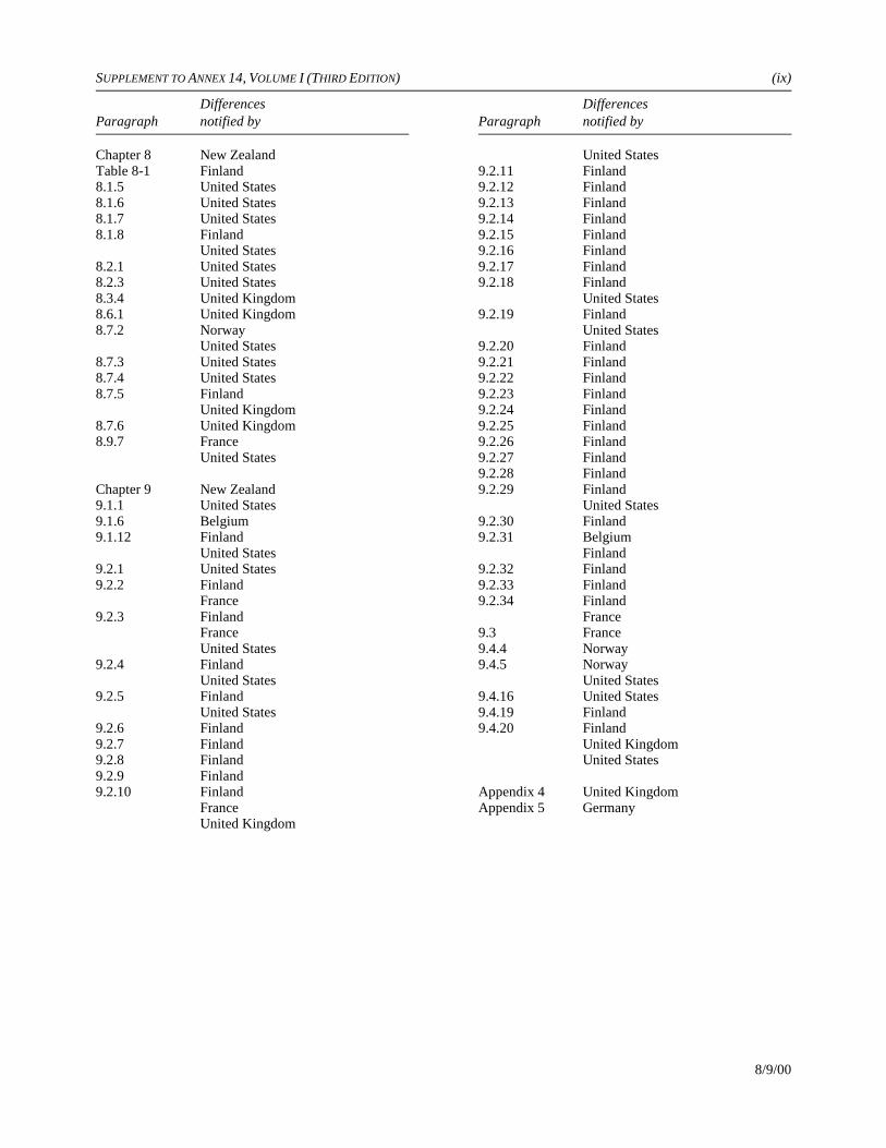
SUPPLEMENT TO ANNEX 14, VOLUME I (THIRD EDITION) (ix)
Differences DifferencesParagraph notified by Paragraph notified by
8/9/00
Chapter 8 New ZealandTable 8-1 Finland8.1.5 United States8.1.6 United States8.1.7 United States8.1.8 Finland
United States8.2.1 United States8.2.3 United States8.3.4 United Kingdom8.6.1 United Kingdom8.7.2 Norway
United States8.7.3 United States8.7.4 United States8.7.5 Finland
United Kingdom8.7.6 United Kingdom8.9.7 France
United States
Chapter 9 New Zealand9.1.1 United States9.1.6 Belgium9.1.12 Finland
United States9.2.1 United States9.2.2 Finland
France9.2.3 Finland
FranceUnited States
9.2.4 FinlandUnited States
9.2.5 FinlandUnited States
9.2.6 Finland9.2.7 Finland9.2.8 Finland9.2.9 Finland9.2.10 Finland
FranceUnited Kingdom
United States9.2.11 Finland9.2.12 Finland9.2.13 Finland9.2.14 Finland9.2.15 Finland9.2.16 Finland9.2.17 Finland9.2.18 Finland
United States9.2.19 Finland
United States9.2.20 Finland9.2.21 Finland9.2.22 Finland9.2.23 Finland9.2.24 Finland9.2.25 Finland9.2.26 Finland9.2.27 Finland9.2.28 Finland9.2.29 Finland
United States9.2.30 Finland9.2.31 Belgium
Finland9.2.32 Finland9.2.33 Finland9.2.34 Finland
France9.3 France9.4.4 Norway9.4.5 Norway
United States9.4.16 United States9.4.19 Finland9.4.20 Finland
United KingdomUnited States
Appendix 4 United KingdomAppendix 5 Germany

SUPPLEMENT TO ANNEX 14, VOLUME I (THIRD EDITION) AUSTRIA 1
8/9/00
CHAPTER 1
1.1 The Austrian regulations distinguish between aerodrome elevation according to ICAO Annex 14 foroperational purposes and aerodrome reference elevation for determining obstruction restrictions.
The aerodrome reference elevation is the elevation of the aerodrome reference point above mean sea levelin terms of the nearest metre.
CHAPTER 3
3.4.2 Although the regulations of Austria provide a runway end safety area of at least 300 m where the codenumber is 3 or 4, at some aerodromes the surrounding terrain does not allow to provide the full length asstated in 3.4.2.
CHAPTER 4
4.1.25 The term “take-off climb surface” is not used and is therefore not defined.
4.2 The specifications concerning approach surfaces are applicable for take-off areas and take-off surfaces aswell.
CHAPTER 5
5.2.1.5 Additional markings are on aprons, i.e. white for service roads (passenger and service vehicles) and red forparking areas of service vehicles and ramp equipment, orange for limit of apron control competence.
5.3.17.10 Exemption may be provided in cases where switched-off taxiway centre lights lead to deterioration of taxiguidance.
5.3.24 For the present, road-holding position lights will not be provided. Reason: on the way to runways mostvehicles use taxiways with ATC clearances.
5.4.3.6 The indication “TORA (RWY)” is added to intersection take-off signs.
CHAPTER 6
6.2.12 Flags used to mark obstructions are 0.5 m square and are coloured in either red or yellow.
Comment on implementation:Chapter 6 will be adopted in accordance with Annex 14 as soon as possible.
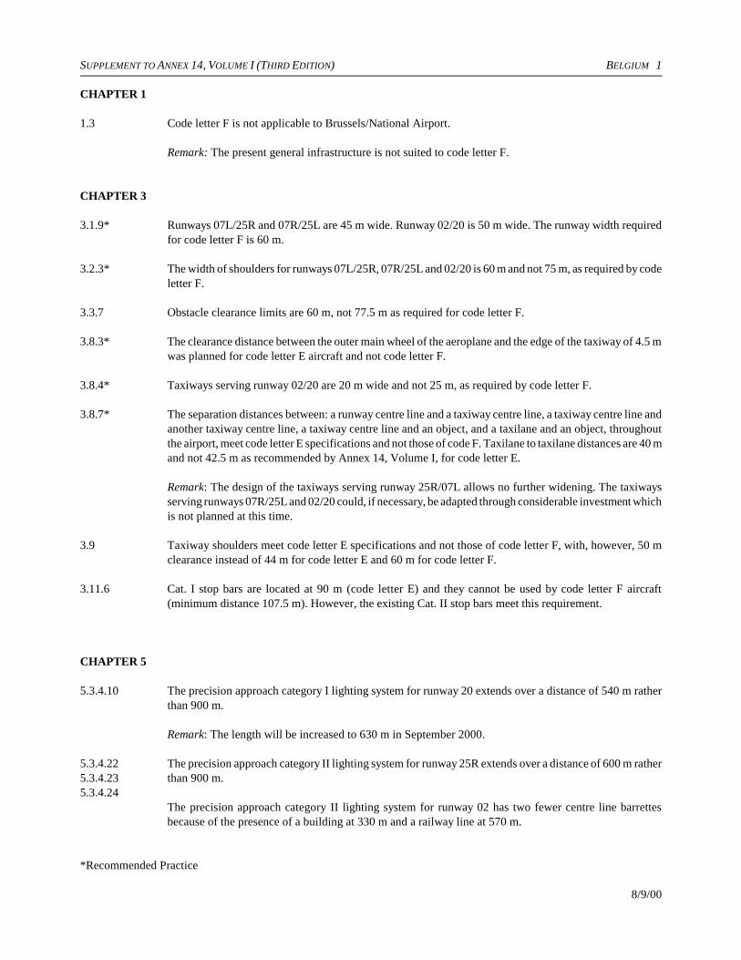
SUPPLEMENT TO ANNEX 14, VOLUME I (THIRD EDITION) BELGIUM 1
8/9/00
CHAPTER 1
1.3 Code letter F is not applicable to Brussels/National Airport.
Remark: The present general infrastructure is not suited to code letter F.
CHAPTER 3
3.1.9* Runways 07L/25R and 07R/25L are 45 m wide. Runway 02/20 is 50 m wide. The runway width requiredfor code letter F is 60 m.
3.2.3* The width of shoulders for runways 07L/25R, 07R/25L and 02/20 is 60 m and not 75 m, as required by codeletter F.
3.3.7 Obstacle clearance limits are 60 m, not 77.5 m as required for code letter F.
3.8.3* The clearance distance between the outer main wheel of the aeroplane and the edge of the taxiway of 4.5 mwas planned for code letter E aircraft and not code letter F.
3.8.4* Taxiways serving runway 02/20 are 20 m wide and not 25 m, as required by code letter F.
3.8.7* The separation distances between: a runway centre line and a taxiway centre line, a taxiway centre line andanother taxiway centre line, a taxiway centre line and an object, and a taxilane and an object, throughoutthe airport, meet code letter E specifications and not those of code F. Taxilane to taxilane distances are 40 mand not 42.5 m as recommended by Annex 14, Volume I, for code letter E.
Remark: The design of the taxiways serving runway 25R/07L allows no further widening. The taxiwaysserving runways 07R/25L and 02/20 could, if necessary, be adapted through considerable investment whichis not planned at this time.
3.9 Taxiway shoulders meet code letter E specifications and not those of code letter F, with, however, 50 mclearance instead of 44 m for code letter E and 60 m for code letter F.
3.11.6 Cat. I stop bars are located at 90 m (code letter E) and they cannot be used by code letter F aircraft(minimum distance 107.5 m). However, the existing Cat. II stop bars meet this requirement.
CHAPTER 5
5.3.4.10 The precision approach category I lighting system for runway 20 extends over a distance of 540 m ratherthan 900 m.
Remark: The length will be increased to 630 m in September 2000.
5.3.4.22 The precision approach category II lighting system for runway 25R extends over a distance of 600 m rather5.3.4.23 than 900 m.5.3.4.24
The precision approach category II lighting system for runway 02 has two fewer centre line barrettesbecause of the presence of a building at 330 m and a railway line at 570 m.
*Recommended Practice
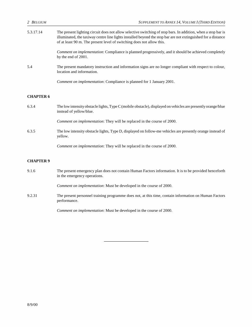
2 BELGIUM SUPPLEMENT TO ANNEX 14, VOLUME I (THIRD EDITION)
8/9/00
5.3.17.14 The present lighting circuit does not allow selective switching of stop bars. In addition, when a stop bar isilluminated, the taxiway centre line lights installed beyond the stop bar are not extinguished for a distanceof at least 90 m. The present level of switching does not allow this.
Comment on implementation: Compliance is planned progressively, and it should be achieved completelyby the end of 2001.
5.4 The present mandatory instruction and information signs are no longer compliant with respect to colour,location and information.
Comment on implementation: Compliance is planned for 1 January 2001.
CHAPTER 6
6.3.4 The low intensity obstacle lights, Type C (mobile obstacle), displayed on vehicles are presently orange/blueinstead of yellow/blue.
Comment on implementation: They will be replaced in the course of 2000.
6.3.5 The low intensity obstacle lights, Type D, displayed on follow-me vehicles are presently orange instead ofyellow.
Comment on implementation: They will be replaced in the course of 2000.
CHAPTER 9
9.1.6 The present emergency plan does not contain Human Factors information. It is to be provided henceforthin the emergency operations.
Comment on implementation: Must be developed in the course of 2000.
9.2.31 The present personnel training programme does not, at this time, contain information on Human Factorsperformance.
Comment on implementation: Must be developed in the course of 2000.

SUPPLEMENT TO ANNEX 14, VOLUME I (THIRD EDITION) CANADA 1
8/9/00
CHAPTER 2
2.6 Canada prepares and distributes pavement evaluation charts for specific aircraft relative to specific airportsupon receipt of a request from an operator. Information required from the operator is: the type of aircraft,the maximum gross weight to be used and the main wheel tire pressure.
2.7 Canada does not provide pre-flight altimeter check locations.
CHAPTER 3
3.1.12* Canada computes runway longitudinal slopes by dividing the difference between the maximum andminimum runway end elevation by the runway length.
3.4.1 Canada does not provide runway end safety areas but does provide a 60 m graded strip beyond the runwayend.
CHAPTER 4
4.1.1 Canada does not establish a conical surface per se but takes into consideration areas outside the horizontalsurface for obstructions that require marking or removal in order to protect aircraft in the vicinity of anaerodrome.
4.1.22Table 4-1
Comment on implementation: Length of inner edge of balked landing surface. Canada cannot always meetthis requirement during the winter months because of snow accumulation.
CHAPTER 5
5.1.1.4* Canada does not require that the location of wind direction indicators be marked by a circular band 15 min diameter but does require that their location be indicated in appropriate aeronautical publications.
5.1.2 Landing direction indicators are not used at Canadian aerodromes.
5.1.4 Signal areas are not used at Canadian aerodromes.
5.2.2.4 Runways within the Canadian Northern Domestic Airspace are designated with reference to true azimuthrather than magnetic azimuth as used in other areas.
5.2.7.2* Canada does not provide runway side stripe markings on precision approach runways except where thereis a lack of contrast between runway edges and the shoulder or surrounding terrain.
5.2.8.2* Canada does not provide taxiway centre line markings on runways where the code number is 1 or 2.
5.2.8.7 Canada permits taxiway centre line markings on straight portions of taxiways to be marked with brokenlongitudinal stripes 3 m in length with 3 m gaps between stripes.
5.2.9 Canada does not provide a specific taxiway holding position marking for category II.
5.2.10 Canada does not provide taxiway-to-taxiway intersection markings.
*Recommended Practice

2 CANADA SUPPLEMENT TO ANNEX 14, VOLUME I (THIRD EDITION)
8/9/00
5.2.11 VOR aerodrome check-point markings are not used at Canadian aerodromes.
5.3.3 Identification beacons are not used in Canada.
5.3.4.2 Canada does not provide a crossbar in simple approach lighting systems.
5.3.4.15 Canada does not use capacitor discharge lights to supplement high-intensity approach lighting systems.
5.3.5.1 It is not Canada’s policy to provide a visual approach slope indicator system where a runway is served byan electronic precision approach system.
Remark: The Canadian standard for visual approach slope indicator systems consists of four light units inthe configuration shown for AVASIS for Figure 5-9(D), Annex 14, Volume I, First Edition.
Figure 5-12 a) Canada provides 9 m wheel clearance for aircraft with eye-to-wheel distance of 13.5 m; 4.5 m wheelclearance for aircraft with eye-to-wheel distance of 7.5 m; and 3 m for aircraft with eye-to-wheel distanceof 3 m.
5.3.6 Circling guidance lights are not used in Canada.
5.3.7 Runway lead-in lighting systems are not used in Canada.
5.3.8 Canada refers to this type of lighting as runway identification lights and sites the units 30 m in front of thethreshold and 12 m from the edge.
5.3.9.7 a) Canada uses blue lights to delineate this area.
5.3.10.3 In the case of a displaced threshold, Canada requires wing bar lights consisting of bidirectional thresholdand runway end lights for both precision and non-precision approach runways.
5.3.14.3 Canada uses blue edge lights in stopways.
5.4.2.9 Canada provides only one HOLD sign for category I runway unless the taxiway is more than 45 m in width.
5.4.5 Canada does not use aerodrome identification signs.
5.5.3.1* Canada does not provide stopway edge markers.
CHAPTER 6
6.2.6* In Canada emergency vehicles may be painted either yellow or red.
CHAPTER 7
7.2.2* Canada does not use taxiway side stripe markings.
*Recommended Practice

SUPPLEMENT TO ANNEX 14, VOLUME I (THIRD EDITION) CHINA (HONG KONG SAR) 1
8/9/00
CHAPTER 1
1.1 “Aerodrome” means any area of land or water designed, equipped, set apart or commonly used for affordingfacilities for the landing and taking-off of aircraft and includes:
a) any area or space, whether on the ground, on the roof of a building, or elsewhere, which is designed,equipped or set apart for affording facilities for the landing and taking-off of aircraft capable ofdescending or climbing vertically; and
b) any such area of land or water or any such area or space, the management of which is vested in theGovernment or in the Chief Executive,
but does not include any area the use of which for affording facilities for the landing and taking-off ofaircraft has been abandoned and has not been resumed.
Comment on implementation: This definition is in line with local legislation. Therefore, withdrawal of thedifference is not considered for the time being.
CHAPTER 3
3.8.21* Straight sections at both ends of the bridges on Taxiway W, Taxiway V and Taxiway V4 are not availableat the following locations:
Taxiway W to H and vice versaTaxiway W to V4 and vice versaTaxiway W to W2 and vice versaTaxiway V to V4 and vice versaTaxiway V to H and vice versa
Comment on implementation: This is compensated by the widened bridges (from the required 44 m to 60 m)to overcome possible oversteering. Therefore, withdrawal of the difference is not considered for the timebeing.
CHAPTER 5
5.2.10 Upon the commissioning of the second runway of the Hong Kong International Airport, taxi-holdingposition markings at the following locations consist of one solid line and one broken line:
Junction of Taxiway A and Taxiway NJunction of Taxiway B and Taxiway NJunction of Taxiway A and Taxiway A4Junction of Taxiway A and Taxiway A5Junction of Taxiway A and Taxiway A6Junction of Taxiway A and Taxiway VJunction of Taxiway A and Taxiway WJunction of Taxiway B and Taxiway VJunction of Taxiway B and Taxiway WJunction of Taxiway A8 and Taxiway AJunction of Taxiway H and Taxiway VJunction of Taxiway H and Taxiway W
* Recommended Practice

2 CHINA (HONG KONG SAR) SUPPLEMENT TO ANNEX 14, VOLUME I (THIRD EDITION)
8/9/00
Comment on implementation: More positive visual information at the critical taxiing intersection is usedin order to provide an enhancement of the markings. Therefore, withdrawal of the difference is notconsidered for the time being.
5.4.3.30 The TORA sign script on TWY A3, A10, J2 and J8 does not show the arrow as specified.
Remark: The specified taxiways intersect the two runways close to the ends of each runway. It is highlyunlikely for the pilots to take-off in the wrong direction because if the wrong direction is taken, only a100 m length of runway would be available for take-off. Therefore, withdrawal of the difference is notconsidered for the time being.

SUPPLEMENT TO ANNEX 14, VOLUME I (THIRD EDITION) DENMARK 1
8/9/00
CHAPTER 3
3.4.1 Runway end safety areas are not provided at all airports in Greenland.
Remark: Difficult due to terrain.

SUPPLEMENT TO ANNEX 14, VOLUME I (THIRD EDITION) FINLAND 1
8/9/00
CHAPTER 3
3.4.4 The following text will be substituted for this Standard:
The width of a runway end safety area shall be at least twice that of the associated runway. However, awidth of 90 m is considered sufficient in all cases.
CHAPTER 5
5.3.3.3 This Standard will be implemented as a recommendation only.
Comment on implementation: Standards 5.3.3.1 and 5.3.3.2 are considered to be adequate in determiningthe operational requirement in Finland. Operational need for an aerodrome beacon or an identificationbeacon, in Finland, is negligible.
5.3.4.1 C A number of precision approach category I runways in Finland are provided with a high intensity simpleapproach lighting system with an additional crossbar located 600 m from the threshold.
Remark: For high intensity simple approach lighting systems, see the ICAO Manual of All-WeatherOperations (Doc 9365), paragraph 6.3.7.
5.3.5.1 c) Comment on implementation: Date of applicability: 1 January 2005.
5.3.18.1 Comment on implementation: This Standard will be implemented in Finland by 1 January 2005.
5.3.20.1 Finland complies with this Standard but with the following addition:
For runways intended to be used for take-offs only, in runway visual range conditions of less than 550 m,runway guard lights are not required if operational procedures exist to limit the number of:
1) aircraft on the manoeuvring area to one at a time; and
2) vehicles on the manoeuvring area to the essential minimum.
5.4.1.7 The following text will be substituted for this Standard:
1) Signs shall be illuminated, either internally or externally, when intended for use:
a) in runway visual range conditions less than 800 m; or
b) at night in association with instrument runways; or
c) at night in association with runways where the code number is 3 or 4.
2) Signs shall be illuminated in accordance with the provisions of Appendix 4 when the runway isintended for landings with runway visual range less than 500 m.
5.4.1.8 The following text will be substituted for this Standard:
Signs shall be retroreflective and/or illuminated when intended for use at night in association with non-instrument runways where the code number is 1 or 2.

2 FINLAND SUPPLEMENT TO ANNEX 14, VOLUME I (THIRD EDITION)
8/9/00
CHAPTER 6
6.1.3 Finland complies with this Standard with the following additions:
a) the marking may be omitted in the case of tree tops forming an obstacle;
b) the marking may be omitted in the case of terrain forming an obstacle not extending above an obstacle-free zone;
c) the marking may be omitted in the case of tree tops forming an obstacle not extending above anobstacle-free zone;
d) the marking may be omitted in the case of tree tops forming an obstacle not considered to constitutea hazard to aeroplanes.
6.3.26 Low intensity obstacle lights displayed in vehicles, including follow-me vehicles, differ from thoseTable 6-3 specified in Table 6-3 as to the flash frequency, maximum allowable intensity and vertical beam spread.
Remark: The low intensity obstacle lights used on vehicles (special warning lamps for motor vehicles) arein accordance with the United Nations Agreement Concerning the Adoption of Uniform Conditions ofApproval and Reciprocal Recognition of Approval for Motor Vehicle Equipment and Parts, RegulationNo. 65, Uniform Provisions Concerning the Approval of Special Warning Lamps for Motor Vehicles.
CHAPTER 7
7.1.4 Finland complies with this Standard with the follow addition:
When the closed marking is used on a temporarily closed runway, it shall be of the form and proportionsas detailed in Figure 7-1, illustration a) or b).
CHAPTER 8
8.1.8 For a runway meant for take-off in runway visual range conditions of less than 550 m, a secondary powersupply capable of meeting the relevant requirements of Table 8-1 shall be provided.
Table 8-1 In Table 8-1, 550 m is substituted for 800 m.
8.7.5 It is not mandatory for a driver of a radio-equipped vehicle, before entering the apron, to establish radiocommunication with ATC or the apron management service.
CHAPTER 9
9.1.12 The intervals between full-scale aerodrome emergency exercises will exceed two years.
Remark: A full-scale exercise may cause expenditure of human resources for outside organizations, suchas hospitals.
9.2.2 to Rescue and fire fighting services specified in these Standards and Recommended Practices are required only9.2.34 at those aerodromes having a permanent air traffic service. Military aerodromes open to civil aircraft but
not serving scheduled air carrier operations do not meet all of these Standards.

SUPPLEMENT TO ANNEX 14, VOLUME I (THIRD EDITION) FINLAND 3
8/9/00
Aerodrome rescue and fire fighting categories 1 and 2 are not applied in Finland, i.e. the aerodromecategory shall be at 3.
9.2.6 Finland complies with this Standard with the following addition:
If, during anticipated periods of reduced activity, the highest category of aeroplane planned to use theaerodrome is 1 or 2, protection shall be provided for these operations if the total annual number ofoperations at the aerodrome is less than 50 000.
9.2.10 Complementary agents are not required at all airports in Finland.
Comment on implementation: Date of applicability: 1 January 2003.
9.4.19 Provision of a temporary threshold marking and early provision of the runway centre line marking arerequired only when practicable. If a temporary threshold marking is not provided, a temporary thresholdshall be indicated with runway threshold identification lights in addition to runway threshold lights and/orwing bar lights. All these shall be high-intensity lights, if applicable.
9.4.20 A light shall be deemed to be unserviceable when the main beam is less than 50 per cent of the valuespecified in the appropriate figure in Appendix 2.
General comment on implementation: The Standards of Amendment 3 will be implemented in Finland by7 September 2000.

SUPPLEMENT TO ANNEX 14, VOLUME I (THIRD EDITION) FRANCE 1
8/9/00
CHAPTER 1
1.1 In France, the runway-holding position is known as the runway stop position. The intermediate holdingposition is known as the intermediate stop position.
1.3 The aerodrome classification system adopted in France is a functional one, based on the characteristics ofthe aviation activities for which the aerodrome is intended, namely:
Category A: Aerodromes intended for long-haul services normally provided under all circumstances.
Category B: Aerodromes intended for medium-haul services normally provided under all circumstancesand for some long-haul services provided under the same conditions but which do not involvea long stage on departure from these aerodromes.
Category C: Aerodromes intended for:
1 — Short-haul, some medium-haul and even long-haul services which only involve shortstages on departure from these aerodromes; and
2 — International tourism.
Category D: Aerodromes intended for aeronautical training, recreational flying and tourism or for certainshort-haul services.
There is therefore no direct correspondence between the above classification and the aerodrome referencecode in Annex 14, Volume I; the following is an approximate table of correspondence.
Category Reference code
A 4 EB 4 DC 3 B to 4 CD 1 A to 3 C
As a result, it is difficult to make a point-by-point notification of differences, in particular regarding thelimitation and removal of obstacles; be that as it may, in this latter field, the applicable specificationsguarantee “safety conditions at least equivalent to those provided for in the Standards and RecommendedPractices of the International Civil Aviation Organization” (Code of Civil Aviation, Article R.241-3).
CHAPTER 2
2.11.4* The French regulations do not include special provisions to express unavailability of rescue and fire fightingservice facilities for periods which are expected to be less than 12 hours.
CHAPTER 3
3.1.15* Minimum radii of curvature are 20 000 m for the runways of Category A aerodromes, 15 000 m forCategory B and 5 000 m for Categories C and D.
.
*Recommended Practice
2 FRANCE SUPPLEMENT TO ANNEX 14, VOLUME I (THIRD EDITION)
8/9/00
3.4 The application of the new Standard will be studied and it can only be implemented progressively.
Remark: There may be obstacles (vegetation) or differences in height after the strip, in the correspondingarea in particular on code number 1 and 2 runways. Verification is therefore necessary.
3.7.1* A radio altimeter operating area is only established for Category II or III precision approach runways.
3.7.3* The width of the radio altimeter operating area for Category II or III precision approaches is 60 m (30 mon each side of the centre line).
3.7.4* The characteristics are as follows:
— average longitudinal slope of less than 2 per cent in absolute value— no local slopes in excess of 5 per cent in absolute value— no local differences in height of more than one metre
In some cases, when the terrain does not correspond to the average slope characteristics and slope changes,an artificial plane may be used.
3.11 The taxi-holding position is known as the runway-stop position.
3.11.53.11.63.11.7*
The French Administration takes the following rules into account in determining the stop position:
a) Runways used under VFR conditions
The distance is determined in relation to the runway edge and is at least equal to:
— 30 m for a paved runway less than 1 000 m long, or an unpaved runway; and— 50 m for a paved runway 1 000 m long or more.
b) Runways used under IFR conditions
— With non-precision approach: the distance is 75 m from the runway centre line.— With precision approach: the distance is at least 150 m from the runway centre line.
However, in Category I, if markings or signs cannot be located 150 m from the runway centre line, adifferent distance may be adopted. It must not be less than:
— 90 m if the runway is used by Category D and E aircraft.— 75 m if the runway is used by Category A, B or C aircraft.
CHAPTER 4
4.1.9 The inner edge of the approach surface is situated at the same elevation as the extended centre line of therunway at right angles to the inner edge.
4.1.13 to4.1.16
The transitional surfaces are known as lateral surfaces.
4.1.27 The inner edge of the take-off climb surface is situated at the same elevation as the extended centre line ofthe runway at right angles to the inner edge.
4.2.1 Some Category D aerodromes do not have a conical surface.
* Recommended Practice

SUPPLEMENT TO ANNEX 14, VOLUME I (THIRD EDITION) FRANCE 3
8/9/00
4.2.9 The runway approach surfaces at aerodromes in Categories A, B and C are horizontal above the higher ofthe following two levels:
— 150 m above the inner edge; and— 100 m above the terrain.
4.2.17 The runway approach surfaces at aerodromes in Categories A, B and C are horizontal above the higher ofthe following two levels:
— 150 m above the inner edge; and— 100 m above the terrain.
CHAPTER 5
5.2.1.5 The taxiway markings are yellow except when a taxiway centre line splits, in which case one of the splitcentre lines is blue and the other orange.
5.2.3.3 For blacktop runways used in VFR conditions or in IFR conditions (excluding precision approaches), and5.2.3.4 for concrete runways used solely in VFR conditions, the French Administration authorizes the use of a5.2.4.5 simplified marking.
5.2.5.2 The aiming point markings are put on all runways 1 500 m in length or longer.
5.2.5.5 For blacktop runways used in VFR conditions or in IFR conditions (excluding precision approaches), andfor concrete runways used solely in VFR conditions, the French Administration authorizes the use of asimplified marking.
5.2.7.2* French regulations do not require the systematic provision of runway side stripe markings on precisionapproach runways.
5.2.10.1* When a precise holding limit has to be defined, an intermediate stop position marking will be used.
5.3.3.12 In France, identification beacons may show flashing-white rather than flashing-green.
5.3.4.1 B The French regulations do no require the regular provision of approach lighting systems for non-precisionapproach runways.
C The French regulations do not require the regular provision of approach lighting systems for Category Iprecision approach runways.
D The French regulations do not require the regular provision of approach lighting systems for Category IIIprecision approach runways if they are not also used for Category II precision approaches.
5.3.5.1 a) The French regulations do not require the regular provision of visual approach slope indicators to serve arunway used by turbojet or other aeroplanes with similar approach guidance requirements.
5.3.12.3 Runway centre line lights are mandatory for take-off in low visibility when the runway visual range (RVR)is lower than 250 m for aircraft of Categories A, B and C and 300 m for aircraft of Category D.
*Recommended Practice
4 FRANCE SUPPLEMENT TO ANNEX 14, VOLUME I (THIRD EDITION)
8/9/00
5.3.15.1 and5.3.15.2*
Taxiway centre line lights are systematically provided only on taxiways with an RVR of less than 150 m.
5.3.15.3* The French Administration applies this provision only in the case of taxiing on an inactive runway and withan RVR of less than 150 m.
5.3.16.2 The French Administration does not apply this provision.
5.3.17.1 The French Administration only requires the provision of stop bars for Category II and III precision5.3.17.2* approach runways except on aerodromes with light traffic (Categories II and III) where taxiing in the5.3.17.3 manoeuvring area is limited to one aircraft at a time.
Remark: In view of the lower RVR limits mentioned, 350 m and 550 m, and the take-off minima authorizedby European regulations, this Standard would require the installation of stop bars on most runways. Thisin unfeasible. This is why only Category II and III runways have been considered.
5.3.17.14 c) The centre line lights will not be visible from the entry side.
5.3.18 The French Administration has no plans to provide taxiway intersection lights.
5.3.20.1 The runway guard lights (Configuration A, Figure 5-23) are installed in France at all the runway-stoppositions on Category II and III precision approach runways in the absence of stop bars. Their installationis recommended at aerodromes with high traffic density.
Remark: In view of the RVR limits mentioned, 550 m and 1 200 m, and the take-off minima authorized byEuropean regulations, this Standard would require the installation of runway guard lights on almost allrunways. This is unfeasible.
5.4.1.6 The French Administration does not fully apply the provisions of Appendix 4. Sign inscription heights maybe lower than the ones mentioned in that Appendix.
5.4.2 The French Administration has established an installation schedule that should end on 31 December 2000.
Remark: Upgrading all French airfields to the Standards requires very considerable investment and work.
5.4.2.5 The French Administration only provides for the installation of the mandatory instruction signs specifiedin 5.4.2.8 (runway designation signs) and/or 5.4.2.9 (category I, II or III stop-position signs) at the runway-stop positions.
Remark: Upgrading all French airfields to the Standards requires very considerable investment and work.
5.4.2.8 In France, the signs specified in 5.4.2.8 are installed at least on the left side of the runway.
Remark: Upgrading all French airfields to the Standards requires very considerable investment and work.Consultation is necessary before adopting this Standard.
5.4.2.10 In France, it is not intended to require the installation of the runway-stop position sign (example “B2”) atrunway-stop positions.
Remark: It can be understood that there is sometimes a need to use this type of sign in the case of multiplestop positions, but it should not be required systematically. Runway designation signs are already oftencomplemented by a location sign (example “B”).
*Recommended Practice
SUPPLEMENT TO ANNEX 14, VOLUME I (THIRD EDITION) FRANCE 5
8/9/00
5.4.2.14 The Cat. II or Cat. III inscription is always placed closest to the taxiway and the runway designation is onthe outside.
20-02 Cat. III Cat. III 20-02left-side sign right-side sign
5.4.3.3 Information signs also include special signs and frequency reminder signs.
Frequency reminder signs:
When passing from one area of responsibility to another, it may be useful to remind pilots or drivers ofvehicles of the frequency associated with the area that they are entering; it is therefore that frequency whichis displayed on the sign.
5.4.3.5 Runway vacated signs are only provided for Category II and III precision approach runways.
5.4.3.7* At some complex intersections, signs displaying a combination of different types of information may beused where required.
5.4.3.10* Signs of the same type as the runway-stop position signs (example “B2”) will be installed at the inter-mediate stop positions at least on the left side of the taxiway.
5.4.3.21 In France, the intersection take-off signs will be installed at least on one side of the taxiway, right or left.
5.4.3.30 In France, the inscriptions on these signs will indicate the value of the distance remaining to the end of therunway (TORA) expressed in metres, but the letter “m” of the unit will not be displayed. The runwaydesignation may also be mentioned.
Remark: The fact of not specifying the unit “m” does not jeopardize safety since confusion with units infeet would give a shorter distance which would alert the pilot.
CHAPTER 7
7.3.1* The French Administration establishes 100 m as the minimum length beyond which a paved pre-thresholdarea not suitable for normal use must be marked with a chevron marking.
CHAPTER 8
8.9.7* The French regulations do not provide for the systematic use of surface movement radar for themanoeuvring area.
CHAPTER 9
9.2.2 The French Administration will not be in a position to apply this Standard in January 2000. The French9.2.3* Administration makes a distinction between flights planned with sufficient time in advance and other
flights.
*Recommended Practice

6 FRANCE SUPPLEMENT TO ANNEX 14, VOLUME I (THIRD EDITION)
8/9/00
9.2.10 The French regulations for aerodrome Categories I and II require the following amounts of extinguishingagents:
Category I 50 kg powder or halons
Category II 250 kg powder or halons
9.2.34 The French regulations provide for the use of respiratory equipment only at aerodrome Category IV orhigher.
9.3 The French Administration does not apply the provisions of this paragraph.

SUPPLEMENT TO ANNEX 14, VOLUME I (THIRD EDITION) GERMANY 1
8/9/00
CHAPTER 2
2.1.52.1.6
Publishing of the aerodrome reference points in WGS-84 will be an ongoing task for some time after thedate of applicability of Amendment 2.
Appendix 5
Table 1Table 2
In Germany the description of obstacles differs as follows from what is given in these tables.
a) Obstacles in the circling area for non-precision and turning departures and at the aerodrome.
b) Significant obstacles in the precision approach and straight departure area.
Table 2 The WGS-84 geoid undulation at aerodrome elevation position will not be published in Germany.
Remark: This item need not be published because for non-precision approaches the MDH is referred to thethreshold position at all German IFR aerodromes.
Table 1Table 52.1.52.1.6
Threshold, runway end: for a few IFR aerodromes these positions cannot be published as from the date ofapplicability.
Remark: Some more time is needed because these positions must be brought into conformity with thedeclared distances specified in the aerodrome licensing document (a formal act of approval by the Nationaladministration).
Comment on implementation:
Annex provision Proposed date of implementation
Appendix 5 It is not intended to comply with this provision.Table 1Table 2
SUPPLEMENT TO ANNEX 14, VOLUME I (THIRD EDITION) JAPAN 1
8/9/00
CHAPTER 3
3.4.2 A runway end safety area is 40 m.
Comment on implementation: No amendment to the current regulation is intended.
CHAPTER 5
5.3.5.42 The length of the obstacle protection surface is 7 400 m.
Comment on implementation: It is difficult to establish the obstacle protection surface of 15 000 m in lengthbecause of mountainous terrain. No amendment to the current regulation is intended.
5.3.14 No provision.
CHAPTER 6
6.3.25 The colour of low intensity obstacle lights displayed on vehicles associated with emergency or security isflashing red.
Date of implementation: March 2005 (provisional).

SUPPLEMENT TO ANNEX 14, VOLUME I (THIRD EDITION) KYRGYZSTAN 1
8/9/00
CHAPTER 3
3.3.2 In the regulations applied in Kyrgyzstan, this segment is reinforced (with pavement) and is 50 m in sizewith a reduction down to 2/3 of its width at the end of the reinforced segment where the code number is 4.
Remark: The implementation of reinforced segments of this size was based on the previous regulatorydocument “Standards of operational serviceability of the civil aerodromes in the USSR”.
SUPPLEMENT TO ANNEX 14, VOLUME I (THIRD EDITION) NETHERLANDS 1
8/9/00
CHAPTER 2
2.1.3 The Netherlands is not making use of CRC to protect the integrity level of critical and essential electronicaeronautical data.
2.1.7 In the Netherlands the geoid undulation at the aerodrome elevation position and the geoid undulation of2.3.1 the threshold will not be published.2.3.22.3.3
2.5.3 In the Netherlands it is not yet considered necessary to determine the geographical coordinates of thetaxiway centre line points in terms of the World Geodetic System — 1984 (WGS-84) geodetic referencedatum.
2.5.4 In the Netherlands it is not yet considered necessary to determine the geographical coordinates of theaircraft stands in terms of the World Geodetic System – 1984 (WGS-84) geodetic reference datum.
2.6.2 a) For pavements intended for aircraft of apron (ramp) mass greater than 6 000 kg, the pavement classificationnumber (PCN) shall be reported.
2.6.52.6.6 a)
The behaviour of a pavement may be classified as rigid (R), flexible (F), special-rigid (SR) or special-flexible (SF).
When classified as special, the standard procedures for determining the ACN-value of an aircraft as givenin the Aerodrome Design Manual, Part 3, are not applicable, and therefore, the reported PCN-value is onlyof indicative value for the present fleet of aircraft.
2.6.8 For pavements intended for aircraft of apron (ramp) mass equal to or less than 6 000 kg and for unpavedairfields in general, the bearing strength shall be reported by the method described in this paragraph.

SUPPLEMENT TO ANNEX 14, VOLUME I (THIRD EDITION) NEW ZEALAND 1
8/9/00
General Comment: New Zealand’s Civil Aviation Rules (CAR) Part 139: Aerodromes — Certification,Operation and Use, is currently being reviewed. More comprehensive advice regarding New Zealand’sdifferences to Annex 14, Volume I, will be provided following issuance of CAR Part 139, which isexpected late in 2000.
CHAPTER 1
General New code letter F for aeroplanes with a wing span of 65 m up to but not including 80 m and an outer mainTable 1-1 gear span of 14 m up to but not including 16 m.
Remark: This requirement will be included in the review of the Civil Aviation Rules Part 139.
Comment on implementation: On issuance of the revised Civil Aviation Rules Part 139, due late 2000.
CHAPTER 3
General Provisions related to code letter F aeroplanes.3.3.2 Length of runway strips.3.3.7 a) Objects on runway strips.
Remark: These requirements will be included in the review of the Civil Aviation Rules Part 139.
Comment on implementation: On issuance of the revised Civil Aviation Rules Part 139, due late 2000.
3.4.1 General3.4.2 Dimensions of runway end safety area (RESA).3.4.3*
Remark: The requirement for RESA is under consideration, and it will be some months before someresolution is finalized.
Comment on implementation: Under consideration.
3.14 New specifications on de/anti-icing facilities.
Remark: These requirements will be included in the review of the Civil Aviation Rules Part 139.
Comment on implementation: On issuance of the revised Civil Aviation Rules Part 139, due late 2000.
CHAPTER 4
Table 4-1 Requirements for code letter F aeroplanes.
Remark: This requirement will be included in the review of the Civil Aviation Rules Part 139.
Comment on implementation: On issuance of the revised Civil Aviation Rules Part 139, due late 2000.
CHAPTER 5
Revised specifications on runway-holding position marking, intermediate holding position marking, runwaycentre line lights, taxiway centre line lights, stop bars, intermediate holding position lights and runway guardlights.
* Recommended Practice

2 NEW ZEALAND SUPPLEMENT TO ANNEX 14, VOLUME I (THIRD EDITION)
8/9/00
Specifications on mandatory instruction markings, marking and lighting of de/anti-icing facilities, alternativeapproach and runway lighting for precision approach runways where the serviceability levels of lights canbe demonstrated and intersection take-off signs.
Remark:These requirements will be included in the review of the Civil Aviation Rules Part 139.
Comment on implementation: On issuance of the revised Civil Aviation Rules Part 139, due late 2000.
CHAPTER 6
Table 6-2 Revised specifications on lighting of obstacles, characteristics of obstacle lights and installation settingTable 6-3 angles for high-intensity obstacle lights.
Remark: These requirements will be included in the review of the Civil Aviation Rules Part 139.
Comment on implementation: On issuance of the revised Civil Aviation Rules Part 139, due late 2000.
CHAPTER 8
Requirements for switch-over times for precision approach runways, Category I, where approaches are overhazardous or precipitous terrain and revised requirements for switch-over times for runways meant for take-off in runway visual range conditions between 550 m and 800 m.
Revised provisions concerning frangibility of non-visual aids on operational areas.
Remark:These requirements will be included in the review of the Civil Aviation Rules Part 139.
Comment on implementation: On issuance of the revised Civil Aviation Rules Part 139, due late 2000.
CHAPTER 9
Provisions concerning a system of preventive maintenance to be employed for precision approachrunways, Categories II and III, as well as provisions concerning Human Factors issues.
Remark: These requirements will be included in the review of the Civil Aviation Rules Part 139.
Comment on implementation: On issuance of the revised Civil Aviation Rules Part 139, due late 2000.

SUPPLEMENT TO ANNEX 14, VOLUME I (THIRD EDITION) NORWAY 1
8/9/00
CHAPTER 2
2.9.6 Norway does not use the method described for continuous friction measuring devices.
Remark: We regard the measured information concerning slippery runway conditions in Norway to betoo inaccurate to be published for official use.
CHAPTER 3
3.4.1 A runway end safety area is not provided at the end of a runway strip where the code number is 1 or 2 andthe runway is an instrument one. It is physically difficult, in some cases impossible, to establish a runwayend safety area at the end of the runway strip at Norwegian aerodromes where the code number is 1 or 2.
CHAPTER 5
5.2.1.4 Runway markings shall be yellow.
Remark: The reason for using yellow markings is due to the need for improved visual references during thewinter season when runways are covered with ice and snow.
5.3.10.1 Runway threshold lights are provided with use of wing bars only on precision approach runways, Cat I.
Remark: In Norway, most precision approach runways have displaced thresholds. When thresholds aredisplaced, the threshold lights must be inset into the pavement. During the winter season, difficulties havebeen experienced in keeping inset lights clear of ice and snow. Norway regards the use of wing bars asthreshold lights sufficient for satisfying the needs of Cat I operations.
CHAPTER 6
6.1.5 When the terrain is regarded as an obstacle, above an obstacle protection surface, obstacles of this type arenormally not marked and lighted, even if the runway is used at night.
6.3.9* When the terrain is regarded as an obstacle, above an obstacle protection surface, obstacles of this type areusually not displayed with top lights.
CHAPTER 8
8.7.2 b) Some of the equipment required for air navigation purposes, penetrating the inner approach surface andthe inner transitional surface, are not frangible.
Remark:The reason for using non-frangible equipment is due to climactic conditions in Norway.
CHAPTER 9
9.4.4* Norway does not regard the method described, for using a continuous friction measuring device, as9.4.5 satisfactory in order to be able to publish necessary information concerning slippery conditions.
* Recommended Practice
SUPPLEMENT TO ANNEX 14, VOLUME I (THIRD EDITION) PORTUGAL 1
8/9/00
CHAPTER 3
3.4.1 Runway end safety areas, as specified in Amendment 3 to Annex 14, Volume I, cannot be implemented at3.4.2 the following international airports:3.4.3*
Lisboa (LPPT) — Runway 17Funchal (LPFU)Faro (LPFR)Joáo Paulo II (LPPD)Horta (LPHR)Flores (LPFL)
Remark: The differences reported herein result from physical or environmental constraints. The individualconstraints are as follows:
Lisboa, Runway 17: A road is located at the end of runway 17.Funchal: A complete renewal project is in progress.Joáo Paulo II and Horta: The runways are located in the periphery of islands. The compliance processis dependent on a change in the declared distances and a corresponding runway lighting systemmodification.Faro: The airport is located in an environmentally protected area. Any modification of the land use isdependent on an environmental impact evaluation.
Comment on implementation:
Existing infrastructures :
Porto (LPPR): will comply by 4 November 1999Santa Maria (LPAZ): will comply by 4 November 1999Porto Santo (LPPS): will comply by 4 November 1999Lisboa (LPPT) runways, 03, 21, 35: will comply by 4 November 1999Funchal (LPFU): will comply after 31 December 2000Flores (LPFL): will comply after 31 December 2000Joáo Paulo II (LPPD): will comply after 2001.
The compliance date after 4 November 1999 will be notified for each airport through the specificAeronautical Information Publication (AIP, NOTAM CIA). The precise compliance date is subordinatedto the planning of the corresponding correction project and the result of an in-depth evaluation of theoperational and safety consequences.
New infrastructures:
Will comply with the provisions of Annex 14, Volume I, including all amendments up to and includingAmendment 3.
* Recommended Practice
SUPPLEMENT TO ANNEX 14, VOLUME I (THIRD EDITION) RUSSIAN FEDERATION 1
8/9/00
CHAPTER 1
1.3 The basic aerodrome classification is the length of the paved runway. Aerodromes are subdivided into sixclasses. In standardizing the taxiway requirements, aeroplanes are subdivided into six groups (indexnumbers) depending on wing span and wheel span. For the largest (index number 6) aeroplanes, a wingspan of up to 65 m and a wheel span of up to 14 m are used. The requirements for index number 6aeroplanes also apply to aeroplanes with a wing span of up to 75 m and a wheel span of up to 10.5 m.
Remark: The national use of a wing span value of 75 m is due to the operation of An-124 type aeroplanes,with a wing span of 73.3 m, at aerodromes. Larger aeroplanes are not currently being used at the country’saerodromes.
CHAPTER 3
3.1.2* The value of the maximum permissible cross-wind component varies from 6 to 12 m/s (from 21.6 to43.2 km/h) as a function of the aerodrome category.
3.1.16* The requirement to provide a line of sight over the entire length of the runway, where a parallel (main)taxiway is not available, is not used. There is a general requirement for a line of sight of not less than halfthe runway length from a height of 3 m, regardless of the availability of a main taxiway.
3.2.3* Shoulders are not provided with a runway width of 60 m or more.
3.3.7 The width of the obstacle-free part of the runway strip is taken to be 60 m from the runway centre line forall aerodrome categories.
3.4 Runway end safety areas are not used. Their functions are performed by sections of the runway strip locatedbeyond the runway ends.
3.6.4* The requirement to provide a stopway coefficient of friction equal to that of the adjacent runway is not used.
3.7 The requirements for the radio altimeter operating area are not used.
3.8.4* The taxiway width is from 7 to 22.5 m as a function of the aeroplane code (group).
3.8.7* As a function of the aeroplane code (group), the distance between parallel taxiway centre lines is from 38to 95 m; the distance between a taxiway centre line and an object is from 22 to 55 m; the distance betweenan aircraft stand taxilane centre line and an object is from 16 to 45 m.
3.8.20* The requirement to provide access for rescue and fire fighting vehicles to aeroplanes on a taxiway bridgeis not used.
3.9.1* The overall width of the taxiway with two shoulders is from 27 to 40.5 m as a function of the aeroplanecode.
3.10 The requirements for taxiway strips are not used.
3.11.4* The requirement for an intermediate holding position on a taxiway is not used.
3.14 The requirements for de/anti-icing facilities are not used.
* Recommended Practice

2 RUSSIAN FEDERATION SUPPLEMENT TO ANNEX 14, VOLUME I (THIRD EDITION)
8/9/00
CHAPTER 4
4.2 Insignificant differences relate to the dimensions and slopes of the obstacle limitation surfaces. Theobstacle limitation surfaces are differentiated according to the runway (aerodrome) categories and to theextent to which the runway is equipped with landing aids.
CHAPTER 5
5.2.5 The aiming point is not used. Its functions are performed by the fixed distance area (300 m from thethreshold).
5.2.7.1 The requirement for a runway side stripe marking, where there is a lack of contrast between the pavementand the adjacent area of the runway strip, is not used. There is a requirement for a side stripe marking fora precision approach runway.
5.2.9.3 Marking of additional runway-holding positions is not used.
5.2.9.7 The runway-holding position marking at a runway/runway intersection is not used.
5.2.10 The intermediate holding position marking at taxiway intersections is not used. The taxiway intersectionpositions are designated by taxiway signs.
5.2.11 The VOR aerodrome check in marking is not used.
5.2.14 The road-holding position marking is not used.
CHAPTER 6
6.2.4* Alternating horizontal bands 0.5 to 6 m wide are used to mark an object up to 100 m high. Not less than1/3 of the height of the object is marked.
CHAPTER 7
7.1 Marking of closed runways and taxiways or parts thereof is not used.
7.3 Different markings in terms of shape, dimensions and colour are used to designate the runway displacedthreshold.
* Recommended Practice

SUPPLEMENT TO ANNEX 14, VOLUME I (THIRD EDITION) SOUTH AFRICA 1
8/9/00
CHAPTER 1
1.1 South Africa will retain the use of the wording “Taxi-Holding Position” and “Taxi-Holding PositionMarking”.
Remark: To avoid confusion when such markings are used on taxiway crossings.
CHAPTER 5
5.2.9 South Africa will retain the use of the wording “Taxi-Holding Position” and “Taxi-Holding PositionMarking”.
Remark: To avoid confusion when such markings are used on taxiway crossings.

SUPPLEMENT TO ANNEX 14, VOLUME I (THIRD EDITION) SPAIN 1
8/9/00
CHAPTER 2
2.9.9* Given the climate of our country, the proposed Recommendation is not applied.
CHAPTER 3
3.1.11* The minimum distance between parallel runways intended for independent parallel approaches is 1 310 m.
3.3.2 It is considered that not all of the airports will have been adapted to the Standard concerning the length ofrunway strips by 1 January 2009.
3.4.3* This Recommended Practice is not complied with in Spain.
3.7 The Recommendation to establish radio altimeter operating areas is applied at those airports requiringcategory II/III precision approaches.
CHAPTER 5
5.2.15 In Spain, the character height for information markings is normally 2 m.
5.3.5 On 31 December 1999, the seven thresholds of four runways at which VASIS systems still operate at thepresent time will have operational PAPI systems.
5.3.17.10 The current facilities are not adapted to this Standard.
5.3.22 By 31 December 1999, all visual docking guidance systems will comply with the specifications.
5.4 Adaptation to the corresponding provisions will be completed during 2001.
CHAPTER 6
6.3.16 This provision is not applied, as ICAO requirements differ from those in our Traffic Code.
* Recommended Practice

SUPPLEMENT TO ANNEX 14, VOLUME I (THIRD EDITION) SWEDEN 1
8/9/00
CHAPTER 5
5.2.5 1 January 2005.
Remark: Swedish regulations contain requirement only for code 4.
5.2.6 1 January 2005.
Remark: Swedish regulations contain requirement only for code 4.
5.2.16.1 Swedish regulations contain no requirement.
Remark: Information markings are deemed to have limited use, given the winter conditions. Signs arerequired to the extent necessary.
CHAPTER 6
General comment: Swedish regulations do not fully correspond with Annex 14. National requirements willbe reviewed within the next three years.
SUPPLEMENT TO ANNEX 14, VOLUME I (THIRD EDITION) SWITZERLAND 1
8/9/00
CHAPTER 5
5.3.5 In general, we do not install a visual approach slope indicator system on a precision approach runway.
CHAPTER 6
6.2.9* The spacing between two markers, where the marker diameter is 60 cm, may be increased to a 40 mmaximum.
Remark: For reasons of uniformity, it is not possible to change given the large number of markedinstallations in our country.
6.3.3* 3 × 80 cd occulting lights may also be used instead of medium-intensity lights.
Remark: Proven practice, high reliability of the lights and good visibility from all angles.
* Recommended Practice

SUPPLEMENT TO ANNEX 14, VOLUME I (THIRD EDITION) UGANDA 1
8/9/00
CHAPTER 2
2.6 PCN for pavements has not been determined. LCN method still in use.
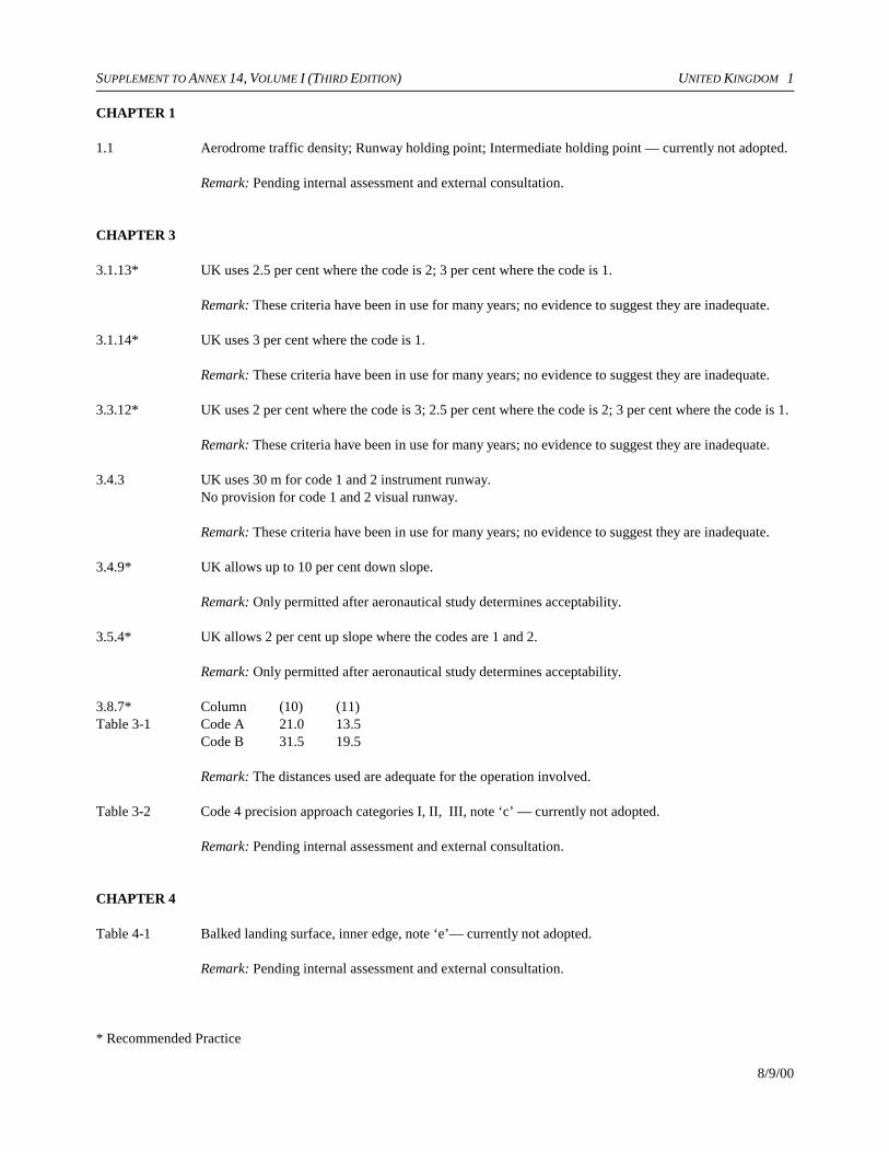
SUPPLEMENT TO ANNEX 14, VOLUME I (THIRD EDITION) UNITED KINGDOM 1
8/9/00
CHAPTER 1
1.1 Aerodrome traffic density; Runway holding point; Intermediate holding point — currently not adopted.
Remark: Pending internal assessment and external consultation.
CHAPTER 3
3.1.13* UK uses 2.5 per cent where the code is 2; 3 per cent where the code is 1.
Remark: These criteria have been in use for many years; no evidence to suggest they are inadequate.
3.1.14* UK uses 3 per cent where the code is 1.
Remark: These criteria have been in use for many years; no evidence to suggest they are inadequate.
3.3.12* UK uses 2 per cent where the code is 3; 2.5 per cent where the code is 2; 3 per cent where the code is 1.
Remark: These criteria have been in use for many years; no evidence to suggest they are inadequate.
3.4.3 UK uses 30 m for code 1 and 2 instrument runway. No provision for code 1 and 2 visual runway.
Remark: These criteria have been in use for many years; no evidence to suggest they are inadequate.
3.4.9* UK allows up to 10 per cent down slope.
Remark: Only permitted after aeronautical study determines acceptability.
3.5.4* UK allows 2 per cent up slope where the codes are 1 and 2.
Remark: Only permitted after aeronautical study determines acceptability.
3.8.7* Column (10) (11) Table 3-1 Code A 21.0 13.5
Code B 31.5 19.5
Remark: The distances used are adequate for the operation involved.
Table 3-2 Code 4 precision approach categories I, II, III, note ‘c’ — currently not adopted.
Remark: Pending internal assessment and external consultation.
CHAPTER 4
Table 4-1 Balked landing surface, inner edge, note ‘e’— currently not adopted.
Remark: Pending internal assessment and external consultation.
* Recommended Practice
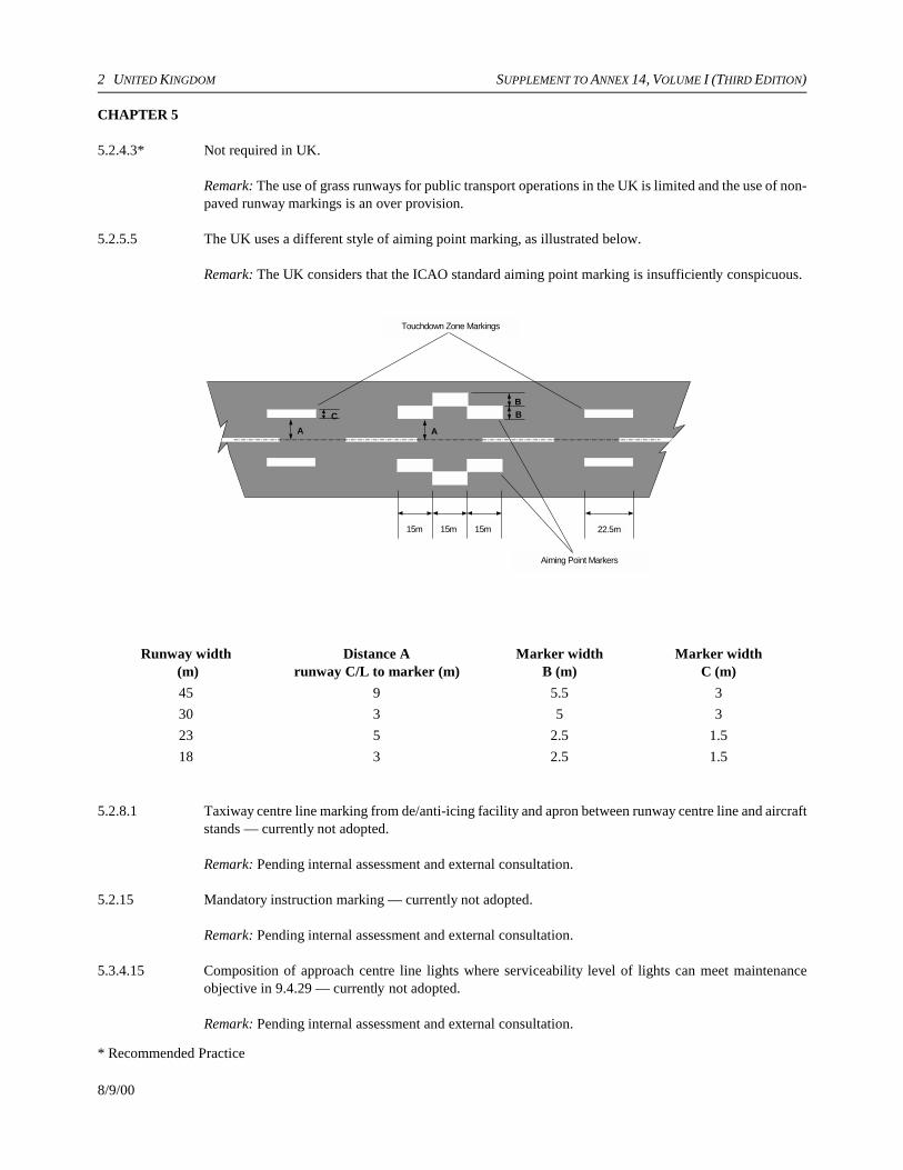
2 UNITED KINGDOM SUPPLEMENT TO ANNEX 14, VOLUME I (THIRD EDITION)
8/9/00
22.5m15m15m15m
Touchdown Zone Markings
Aiming Point Markers
A A
BBC
CHAPTER 5
5.2.4.3* Not required in UK.
Remark: The use of grass runways for public transport operations in the UK is limited and the use of non-paved runway markings is an over provision.
5.2.5.5 The UK uses a different style of aiming point marking, as illustrated below.
Remark: The UK considers that the ICAO standard aiming point marking is insufficiently conspicuous.
Runway width (m)
Distance Arunway C/L to marker (m)
Marker widthB (m)
Marker widthC (m)
45 9 5.5 330 3 5 323 5 2.5 1.518 3 2.5 1.5
5.2.8.1 Taxiway centre line marking from de/anti-icing facility and apron between runway centre line and aircraftstands — currently not adopted.
Remark: Pending internal assessment and external consultation.
5.2.15 Mandatory instruction marking — currently not adopted.
Remark: Pending internal assessment and external consultation.
5.3.4.15 Composition of approach centre line lights where serviceability level of lights can meet maintenanceobjective in 9.4.29 — currently not adopted.
Remark: Pending internal assessment and external consultation.
* Recommended Practice

SUPPLEMENT TO ANNEX 14, VOLUME I (THIRD EDITION) UNITED KINGDOM 3
8/9/00
5.3.4.22 Composition of approach lights where serviceability level of lights can meet maintenance objective in9.4.26 — currently not adopted.
Remark: Pending internal assessment and external consultation.
5.3.4.24 Composition of approach lights (side rows) where serviceability of lights can meet maintenance objectivein 9.4.26 — currently not adopted.
Remark: Pending internal assessment and external consultation.
5.3.4.30 Composition of Cat II/III centre line approach lighting where serviceability of lights can meet maintenanceobjective in 9.4.26 — currently not adopted.
Remark: Pending internal assessment and external consultation.
5.3.4.32 Composition of approach lights where serviceability can meet maintenance objective in 9.4.26 — currently5.3.4.33 not adopted.
Remark: Pending internal assessment and external consultation.
5.3.5.42 UK uses a plane 1E below lower boundary of on slope signal originating 90 m from units where LDA1 200 m or greater, 60 m where LDA 800 m – 1 199 m and 30 m where LDA <800 m, diverging at 15E fromrunway edge out to 15 NM.
Remark: This practise has been in existence since PAPI was originally designed; no safety related incidentsto justify introducing more penalizing criteria.
5.3.12.2* Not required in UK.
Remark: No demonstrated safety benefit. Markings and HI edge lights considered sufficient.
5.3.12.4* Not required in UK.
Remark: No demonstrated safety benefit. Markings and HI edge lights considered sufficient.
5.3.15.1 Provision of continuous taxiway lights between runway and stands in RVR less than 350 m — currentlynot adopted.
Remark: Pending internal assessment and external consultation.
5.3.15.7 UK uses amber/green both ways within OFZ.
Remark: The pattern is intended to remind pilots when they are within OFZ/ILS protected areas.
5.3.15.11 c)* UK uses 30 m spacing for taxiways used in RVR 200 m and above, 15 m spacing when used in RVR<200 m.
Remark: Tests and practical experience confirm that spacing is sufficient.
5.3.15.13* UK uses 15 m spacing for taxiways used in RVR 200 m and above, 7.5 m where used in RVR <200 m.
Remark: Tests and practical experience confirm that spacing is sufficient.
*Recommended Practice
4 UNITED KINGDOM SUPPLEMENT TO ANNEX 14, VOLUME I (THIRD EDITION)
8/9/00
5.3.15.17* UK uses 15 m spacing for exits used in RVR 200 m and above, 7.5 m where used in RVR <200 m.
Remark: Tests and practical experience confirm that spacing is sufficient.
5.3.15.18* UK uses 30 m spacing for taxiways used in RVR 200 m and above, 15 m spacing where used in RVR<200 m.
Remark: Tests and practical experience confirm that spacing is sufficient.
5.3.16.6 UK also uses omni-directional taxiway edge lights. Use of omni-directional edge lights is gradually beingphased out.
5.3.19 De/anti-icing facility exit lights — currently not adopted.
Remark: Pending internal assessment and external consultation.
5.3.22.11* UK uses systems not aligned for use by both pilots.
Remark: Many of these systems were in use before guidance material was produced. They are graduallybeing replaced with compliant units.
5.3.22.14 UK uses systems where pilot has to turn head.
Remark: Pending internal assessment and external consultation.
5.3.22.16* UK uses systems not aligned for use by both pilots.
Remark: Pending internal assessment and external consultation.
5.4.1.9 Blank face on variable message sign — currently not adopted.
Remark: Pending internal assessment and external consultation.
5.4.2.8 Runway designation sign location — currently not adopted.
Remark: Pending internal assessment and external consultation.
5.4.3.5 Not used in UK.
Remark: UK uses a location sign.
5.4.3.14* UK uses taxiway ending sign but not just at ‘T’ junctions.
Remark: UK uses a taxiway ending sign which is a location sign with a yellow diagonal.
5.4.3.17 Not all runway exit signs on same side of runway as exit.
Remark: Location is on same side where possible.
5.4.3.21 Location of intersection take-off sign — currently not adopted.
Remark: Pending internal assessment and external consultation.
* Recommended Practice
SUPPLEMENT TO ANNEX 14, VOLUME I (THIRD EDITION) UNITED KINGDOM 5
8/9/00
3mTaxiway C/L
6m
0.9m
5.4.3.25* Taxiway ending sign at ‘T’ junctions not always located as specified.
Remark: Taxiway ending signs should be located well before end of taxiway.
5.4.3.26 Not used in UK.
5.4.3.27 All UK location signs have yellow border.
5.4.3.30 Inscription on intersection take-off sign — currently not adopted.
Remark: Pending internal assessment and external consultation.
5.5.3.1* Not used in UK.
Remark: When standard marking agreed, UK will implement.
5.5.3.2 Not used in UK.
Remark: When standard marking agreed, UK will implement.
CHAPTER 6
6.2.8* Not required in UK.
6.3.16 Provision of medium-intensity obstacle lights Type A/B/C — currently not adopted.6.3.176.3.18 Remark: Pending internal assessment and external consultation.
CHAPTER 7
7.1.4 UK uses elongated legs 0.9 m wide as illustrated:
* Recommended Practice
6 UNITED KINGDOM SUPPLEMENT TO ANNEX 14, VOLUME I (THIRD EDITION)
8/9/00
7.2.2* Inner edge marks outer edge of load-bearing surface.
CHAPTER 8
8.3.4* Not used in UK.
Remark: UK is working on minimum acceptable levels of lighting.
8.6.1 Design and construction of new facilities to incorporate security measures — currently not adopted.
Remark: Pending internal assessment and external consultation.
8.7.5 Location of equipment or installation with reference to runway strip and extended centre line — currentlynot adopted.
Remark: Pending internal assessment and external consultation.
8.7.6 Frangibility and mounting of equipment or installations located on or near Cat. I/II/III precision approachrunways — currently not adopted.
Remark: Pending internal assessment and external consultation.
CHAPTER 9
9.2.10 At all aerodromes, up to 50 per cent of the complimentary media may be replaced by water for foamproduction to performance level B.
9.4.20 Serviceability requirements for lights in visual aids — currently not adopted.
Remark: Pending internal assessment and external consultation.
Appendix 4
paragraph 11 Not specified in UK.

SUPPLEMENT TO ANNEX 14, VOLUME I (THIRD EDITION) UNITED STATES 1
8/9/00
CHAPTER 1
1.1 De/anti-icing facility definition was revised to include slush as another form of contamination to beremoved. Holdover time definition revised to include commencement of holdover time for one-stepprocedures.
1.2.1 Airports in the United States are for the most part owned and operated by local governments and quasi-governmental organizations formed to operate transportation facilities. The Federal government providesair traffic control, operates and maintains navaids, provides financial assistance for airport development,certificates major airports and issues standards and guidance for airport planning, design and operationalsafety.
There is general conformance with the Standards and Recommended Practices of Annex 14, Volume I.At airports with scheduled passenger service using aircraft having more than nine seats, compliance withStandards is enforced through regulation and certification. At other airports, compliance is achievedthrough the agreements with individual airports under which federal development funds were granted;or, through voluntary actions.
1.3.11.3.21.3.31.3.4
In the United States the Airport Reference Code is a two-component indicator relating the standards usedin the airport’s design to a combination of dimensional and operating characteristics of the largestaircraft expected to use the airport. The first element, Aircraft Approach Category, corresponds to theICAO PANS-OPS approach speed groupings. The second, Airplane Design Group (ADG), correspondsto the wingspan groupings of code element 2 of the Annex 14, Aerodrome Reference Code. See below:
Airport Reference Code (ARC)
Aircraft ApproachCategory
ApproximateAnnex 14
Code Number
A 1 Airport designed
B 2 for B747-400
C 3 ARC D-V
D 4
E —
Airplane DesignGroup
CorrespondingAnnex 14 Code
Letter
I A
II B
III C
IV D
V E
VI F (proposed)
CHAPTER 2
2.2.1 Comment on implementation: The aerodrome reference point is recomputed when the ultimate planneddevelopment of the aerodrome is changed.
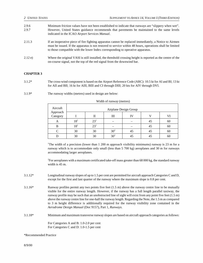
2 UNITED STATES SUPPLEMENT TO ANNEX 14, VOLUME I (THIRD EDITION)
8/9/00
2.9.6 Minimum friction values have not been established to indicate that runways are “slippery when wet”.2.9.7 However, United States guidance recommends that pavements be maintained to the same levels
indicated in the ICAO Airport Services Manual.
2.11.3 If an inoperative piece of fire fighting apparatus cannot be replaced immediately, a Notice to Airmenmust be issued. If the apparatus is not restored to service within 48 hours, operations shall be limitedto those compatible with the lower Index corresponding to operative apparatus.
2.12 e) Where the original VASI is still installed, the threshold crossing height is reported as the centre of theon-course signal, not the top of the red signal from the downwind bar.
CHAPTER 3
3.1.2* The cross-wind component is based on the Airport Reference Code (ARC): 10.5 kt for AI and BI; 13 ktfor AII and BII; 16 kt for AIII, BIII and CI through DIII; 20 kts for AIV through DVI.
3.1.9* The runway widths (metres) used in design are below:
Width of runway (metres)
AircraftApproachCategory
Airplane Design Group
I II III IV V VI
A 181 231 – – 45 60
B 181 231 – – 45 60
C 30 30 302 45 45 60
D 30 30 302 45 45 60
1The width of a precision (lower than 1 200 m approach visibility minimums) runway is 23 m for arunway which is to accommodate only small (less than 5 700 kg) aeroplanes and 30 m for runwaysaccommodating larger aeroplanes.
2For aeroplanes with a maximum certificated take-off mass greater than 68 000 kg, the standard runwaywidth is 45 m.
3.1.12* Longitudinal runway slopes of up to 1.5 per cent are permitted for aircraft approach Categories C and D,except for the first and last quarter of the runway where the maximum slope is 0.8 per cent.
3.1.16* Runway profiles permit any two points five feet (1.5 m) above the runway centre line to be mutuallyvisible for the entire runway length. However, if the runway has a full length parallel taxiway, therunway profile may be such that an unobstructed line of sight will exist from any point five feet (1.5 m)above the runway centre line for one-half the runway length. Regarding the Note, the 1.5 m as comparedto 3 m height difference is additionally required for the runway visibility zone contained in theAerodrome Design Manual (Doc 9157), Part 1, Runways.
3.1.18* Minimum and maximum transverse runway slopes are based on aircraft approach categories as follows:
For Categories A and B: 1.0-2.0 per centFor Categories C and D: 1.0-1.5 per cent
*Recommended Practice
SUPPLEMENT TO ANNEX 14, VOLUME I (THIRD EDITION) UNITED STATES 3
8/9/00
3.2.3* The United States does not require that the minimum combined runway and shoulder widths equal 60 m.The widths of shoulders are determined independently.
3.2.4* The transverse slope on the innermost portion of the shoulders can be as high as 5 per cent.
3.3.33.3.4*3.3.5*
A strip width of 120 m is used for code 3 and 4 runways for precision, non-precision and non-instrumented operations. For code 1 and 2 precision runways, the width is 120 m. For non-precision/visual runways, widths vary from 37.5 m up to 120 m.
3.3.7 The frangibility and object removal requirement are applicable only to the FAA runway safety area(RSA) and the obstacle free zone (OFZ). The RSA functions similarly to the ICAO “graded portion” ofthe runway strip. The difference is less than 1.3 m; that is, the FAA Standard measure 76.2 m ascompared to 77.5 m under Annex 14. However, the area beyond the RSA, the runway object free area,measures 120 m and requires object removal, but not frangibility for permitted objects.
3.3.9* Airports used exclusively by small aircraft (U.S. Airplane Design Group I) may be graded to distancesas little as 18 m from the runway centre line.
3.3.14* The maximum transverse slope of the graded portion of the strip can be 3 per cent for Aircraft ApproachCategories C and D and 5 per cent for Aircraft Approach Categories A and B.
3.3.15* The United States does not have standards for the maximum transverse grade on portions of the runwaystrip falling beyond the area that is normally graded.
3.3.17* Runways designed for use by smaller aircraft under non-instrument conditions may be graded todistances as little as 18 m from the runway centre line (U.S. Airplane Design Groups I and II).
3.4.2 For certain code 1 runways the runway end safety areas may be only 72 m.
3.6.4* Pavement friction measurements are taken for only the runway with full strength pavement and not forthe surface of stopways.
3.7.1*3.7.2*
The United States does not provide Standards or Recommended Practices for radio altimeter operatingareas.
3.8.3* The United States specifies a 6 m clearance for Design Group VI aeroplanes.
3.8.4* The taxiway width for Design Group VI aircraft is 30 m.
3.8.5* The United States also permits designing taxiway turns and intersections using the judgmentaloversteering method.
3.8.7* Minimum separations between runway and taxiway centre lines are shown in Table 1. Minimumseparations between taxiways and taxilanes and between taxiway/taxilanes and fixed/moveable objectsare shown in Table 2. Generally, United States separations are larger for non-instrumented runways, andsmaller for instrumented runways, than in the Annex. Values are also provided for aircraft withwingspans up to 80 m. For Code F, separations in all cases equal 180 m.
3.8.8* Longitudinal grades (slopes) for taxiways are based on approach category (code number) rather thanwing span (code letter). However, values are: Code 1 and 2 = 3.0 per cent; Code 3 and 4 = 1.5 per cent.
*Recommended Practice

4 UNITED STATES SUPPLEMENT TO ANNEX 14, VOLUME I (THIRD EDITION)
8/9/00
3.8.10* Line-of-sight standards for taxiways are not provided in United States practice, but there is a requirementthat the sight distance along a runway, from an intersecting taxiway, must be sufficient to allow a taxiingaircraft to safely enter or cross the runway.
3.8.11* Transverse slopes of taxiways are based on aircraft approach categories. For Categories C and D slopesare 1.0-1.5 percent; for A and B 1.0-2.0 per cent.
3.9.1* The overall width of the taxiway plus shoulders is 54 m as compared to 60 m for the Annex.
Remark: For Code F aircraft the emphasis is on wider full strength pavement rather than shoulders. TheUnited States requires 30 m taxiway widths as compared to the 25 m width under 3.8.4.
3.10.5* Grading of runway strips are downward and are based on aircraft approach categories, that is codenumbers. Furthermore, we recommend a downward slope from the horizontal for the first three metresbeyond the taxiway or shoulders followed by a downward range of 1.5-3.0 per cent for the remainderof the strip.
3.11.6 Regarding Table 3-2, FAA runway centre line to taxi-holding position, etc., a separation for code 1 isTable 3-2 c. 38 m for non-precision operations and 53 m for precision. Code 3 and 4 precision operations require a
separation of 75 m, except for “wide bodies”, which require 85 m. There is no standard clearance forCode F aircraft at this time.
3.14.4* The ability to bypass de-icing facilities is a standard and not a recommendation.
3.14.9* Only Code D and E clearances are shorter; that is, 2 m and 0.5 m, respectively.
3.14.10* Only Codes A, B and D are shorter; that is, 2.75 m, 1.5 m and 1.0 m, respectively.
CHAPTER 4
4.1 Obstacle limitation surfaces similar to those described in 4.1-4.20 are found in Federal AviationRegulation Part 77.
4.1.21 A balked landing surface is not used.
4.1.25 The United States does not establish take-off climb obstacle limitation areas and surfaces per se but doesspecify protective surfaces for each end of the runway based on the type of approach proceduresavailable or planned. The dimensions and slopes for these surfaces and areas are listed in Table 3.
4.2 For Code C, D and F aircraft, the width of the OFZ inner approach equals 120 m.Table 4-1
Remark: Research and development for the width measurement for Code F are ongoing. Flight Standardswill issue, upon completion of the R & D simulation, an FAA document with results and possible newrecommendations.
CHAPTER 5
5.2.1.8* The United States does not require unpaved taxiways to be marked.
5.2.2.2* The United States does not require a runway designator marking for unpaved runways.
* Recommended Practice

SUPPLEMENT TO ANNEX 14, VOLUME I (THIRD EDITION) UNITED STATES 5
8/9/00
5.2.2.4 Zeros are not used to precede single digit runway markings. An optional configuration of the numeral 1is available to designate a Runway 1 and to prevent confusion with the runway centre line.
5.2.4.2*5.2.4.3*
Threshold markings are not required, but sometimes provided, for non-instrument runways that do notserve international operations.
5.2.4.5 The current United States standard for threshold designation is eight stripes, except that more than eightstripes may be used on runways wider than 45 m. After 1 January 2008, the United States standard willcomply with Annex 14.
5.2.4.6 The width and spacing of threshold stripes will comply with Annex 14 after 1 January 2008.
5.2.4.10 When a threshold is temporarily displaced, there is no requirement that runway or taxiway edgemarkings, prior to the displaced threshold, be obscured. These markings are removed only if the area isunsuitable for the movement of aircraft.
5.2.5.25.2.5.3*
Aiming point markings are required on precision instrument runways and code 3 and 4 runways usedby jet aircraft.
5.2.5.4 The aiming point marking commences 306 m from the threshold at all runways.
5.2.6.3 The United States pattern for touchdown zone markings, when installed on both runway ends, is onlyapplicable to runways longer than 4 990 feet. On shorter runways, the three pairs of markings closestto the runway midpoint are eliminated.
5.2.6.4 The United States standard places the aiming point marking 306 m from the threshold where it replacesone of the pairs of three-stripe threshold markings. The 306 m location is used regardless of runwaylength.
5.2.6.5* Touchdown zone markings are not required at a non-precision approach runway, though they may beprovided.
5.2.7.4* Runway side stripe markings on a non-instrument runway may have an overall width of 0.3 m.
5.2.8.3 Taxiway centre line markings are never installed longitudinally on a runway even if the runway is partof a standard taxi-route.
5.2.9.6* The term “ILS” is used instead of CAT I, CAT II, CAT III.
5.2.9.7 Runway-holding position markings at runway/runway intersections are as shown in Figure 5-6,Pattern A.
5.2.11.45.2.11.5*5.2.11.6*
Check-point markings are provided, but the circle is 3 m in diameter and the directional line may be ofvarying width and length. The color is the yellow used for taxiway markings.
5.2.12 Standards for aircraft stand markings are not provided.
5.2.13.1* Apron safety lines are not required although many aerodromes have installed them. The United Statesdoes not set marking standards for aprons, finding it more effective to let airports and airlines manageactivities related to aircraft parking.
*Recommended Practice

6 UNITED STATES SUPPLEMENT TO ANNEX 14, VOLUME I (THIRD EDITION)
8/9/00
5.2.14.1 The United States does not have standards for holding position markings on roadways that crossrunways. Local traffic control practices are used.
5.3.1.15.3.1.2*
The United States does not have regulations to prevent the establishment of non-aviation ground lightsthat might interfere with airport operations.
5.3.1.35.3.1.4
New approach lighting installations will meet the frangibility requirements. Some existing non-frangiblesystems may not be replaced before 1 January 2005.
5.3.2.1*5.3.2.2*5.3.2.3*
There is no requirement for an airport to have emergency runway lighting available if it does not havea secondary power source. Some airports do have these systems, and there is an FAA specification forthese lights.
5.3.3.15.3.3.3
Only airports served by aircraft having more than 30 seats are required to have a beacon, though theyare available at many others.
5.3.3.6 Although the present United States standard for beacons calls for 24-30 flashes per minute, some olderbeacons may have flash rates as low as 12 flashes per minute.
5.3.3.8 Coded identification beacons are not required and are not commonly installed. Typically, airport beaconsconforming to 5.3.3.6 are installed at locations served by aircraft having more than 30 seats.
5.3.4.1 While the United States has installed an approach light system conforming to the specifications in5.3.4.10 to 5.3.4.19, it also provides for a lower cost system consisting of medium intensity approachlighting and sequenced flashing lights (MALSF) at some locations.
5.3.4.2 In addition to the system described in 5.3.4.1, a system consisting of omnidirectional strobe lights(ODALS) located at 90 m intervals extending out to 450 m from the runway threshold is used at somelocations.
5.3.4.10 to5.3.4.19
The United States standard for a precision approach Category I lighting system is medium intensityapproach lighting system with runway alignment indicator lights (MALSR). This system consists of3 m barrettes at 60 m intervals out to 420 m from the threshold and sequenced flashing lights at 60 mintervals from 480 m to 900 m. A crossbar 20 m in length is provided 300 m from the threshold. Thetotal length of this system is dependent upon the ILS glide slope path angle. For angles 2.75E and higher,the length is 720 m.
5.3.4.18 The capacitor discharge lights can be switched on or off when the steady-burning lights of the approachlighting system are operating. However, they cannot be operated when the other lights are not inoperation.
5.3.4.22 The United States standard for a precision approach Category II and III lighting system has a total lengthdependent upon the ILS glide path angle. For angles 2.75E and higher, the length is 720 m.
5.3.4.35 The capacitor discharge lights can be switched on or off when the steady-burning lights of the approachlighting system are operating. However, they cannot be operated when the other lights are not inoperation.
5.3.5.1 Visual approach slope indicator systems are not required for all runways used by turbojets exceptrunways involved with land and hold short operations that do not have an electronic glideslope system.
*Recommended Practice

SUPPLEMENT TO ANNEX 14, VOLUME I (THIRD EDITION) UNITED STATES 7
8/9/00
5.3.5.2 In addition to PAPI and APAPI systems, VASI and AVASI type systems remain in service at UnitedStates airports with commercial service. Smaller general aviation airports may have various otherapproach slope indicators including tri-color and pulsating visual approach slope indicators.
5.3.5.35.3.5.4
Visual approach slope indicator systems are not required for all runways used by turbojets exceptrunways involved with land and hold short operations that do not have an electronic glideslope system.
5.3.5.27 The United States standard for PAPI allows for the distance between the edge of the runway and the firstlight unit to be reduced to 9 m for code 1 runways used by non-jet aircraft.
5.3.5.42 The PAPI obstacle protection surface used is as follows: The surface begins 90 m in front of the PAPIsystem (toward to the threshold) and proceeds outward into the approach zone at an angle 1E less thanthe aiming angle of the third light unit from the runway. The surface flares 10E on either side of theextended runway centre line and extends four statute miles from its point of origin.
5.3.8.4 The United States permits the use of omnidirectional runway threshold identification lights.
5.3.13.2 The United States does not require the lateral spacing of touchdown zone lights to be equal to that oftouchdown zone marking when runways are less than 45 m wide.
5.3.14 The United States has no provision for stopway lights.
5.3.15.15.3.15.2*
Taxiway centre line lights are required only below 183 m runway visual range (RVR) on designated taxiroutes. However, they are generally recommended whenever a taxiing problem exists.
5.3.15.4 Taxiway centre line lights are not provided on runways forming part of a standard taxi route even forlow visibility operations. Under these conditions, the taxi path is coincident with the runway centre lineand the runway lights are illuminated.
5.3.15.7 Comment on Implementation: The United States standard for taxiway centre line lights on exit taxiwayswas brought into compliance with this Annex 14 provision on 1 September 1998. However, UnitedStates airports are still in the process of implementing the Standard.
5.3.15.10* The United States permits an offset of up to 60 cm.
5.3.16.2 Taxiway edge lights are not provided on runways forming part of a standard taxi route.
5.3.17.15.3.17.2*5.3.17.35.3.17.4*5.3.17.5*
Stop bars are required only for RVR conditions less than a value of 183 m at taxiway/runwayintersections where the taxiway is lighted during low visibility operations. Once installed, controlledstop bars are operated at RVR conditions less than a value of 350 m.
5.3.17.6 Elevated stop bar lights are normally installed longitudinally in line with taxiway edge lights. Whereedge lights are not installed, the stop bar lights are installed not more than 3 m from the taxiway edge.
5.3.17.9 The beamspread of elevated stop bar lights differs from the in-pavement lights. The inner isocandelacurve for the elevated lights is ±7 hor. and ±4 vert.
5.3.17.10 The United States standard for stop bars, which are switchable in groups, does not require the taxiwaycentre line lights beyond the stop bars to be extinguished when the stop bars are illuminated. Thetaxiway centre line lights which extend beyond selectively switchable stop bars are grouped into two
*Recommended Practice

8 UNITED STATES SUPPLEMENT TO ANNEX 14, VOLUME I (THIRD EDITION)
8/9/00
segments of approximately 45 m each. A sensor at the end of the first segment re-illuminates the stopbar and extinguishes the first segment of centre line lights. A sensor at the end of the second segmentextinguishes that segment of centre line lights.
5.3.18.1 Taxiway intersection lights are also used at other hold locations on taxiways such as low visibilityholding points.
5.3.18.2* Taxiway intersection lights are collocated with the taxiway intersection marking. The marking is locatedat the following distances from the centre line of the intersecting taxiway:
Aeroplane Design Group Distance (m)I 13.5II 20III 28.5IV 39V 48.5VI 59
5.3.20.15.3.20.2*
Runway guard lights are required only for RVR conditions less than a value of 350 m.
5.3.20.45.3.20.5
Runway guard lights are placed at the same distance from the runway centre line as the aircraft holdingdistance, or within a few feet of this location.
5.3.20.17 The new United States standard for in-pavement runway guard lights complies with Annex 14. However,there may be some existing systems that do not flash.
5.3.21 The United States does not set aviation standards for floodlighting aprons.
5.3.22 The United States does not provide standards for visual docking guidance systems.
5.3.24.1 The United States does not have a requirement for providing road-holding position lights during RVRconditions less than a value of 350 m.
5.4.1.3 Signs are often installed a few centimetres taller than specified in Annex 14, Volume 1, Table 5-4.
5.4.1.6 Sign inscriptions are slightly larger, and margins around the sign slightly smaller, than indicated inAnnex 14, Volume 1, Appendix 4.
5.4.1.7 The sign luminance requirements are not as high as specified in Appendix 4. The United States does notspecify a night-time color requirement in terms of chromaticity.
5.4.2.25.4.2.4
All signs used to denote precision approach holding positions have the legend “ILS”.
5.4.2.7 United States practice uses the NO ENTRY sign to prohibit entry by aircraft only.
5.4.2.9 The second mandatory instruction sign is usually not installed unless added guidance is necessary.
5.4.2.10 All signs used to denote precision approach holding positions have the legend “ILS”.
*Recommended Practice
SUPPLEMENT TO ANNEX 14, VOLUME I (THIRD EDITION) UNITED STATES 9
8/9/00
5.4.2.11 The second mandatory instruction sign is usually not installed unless added guidance is necessary.
5.4.2.14 All signs used to denote precision approach holding positions have the legend “ILS”.
5.4.2.15 Signs for holding aircraft and vehicles from entering areas where they would infringe on obstaclelimitation surfaces or interfere with navaids are inscribed with the designator of the approach, followedby the letters “APCH”. For example: “15-APCH”.
5.4.2.18 All signs used to denote precision approach holding positions have the legend “ILS”.
5.4.3.15 United States practice is to install signs about 3 to 5 m closer to the taxiway/runway (See Annex 14,Table 5-4).
5.4.3.17 The United States does not have standards for the location of runway exit signs.
5.4.3.27 A yellow border is used on all location signs, regardless of whether they are stand-alone or collocatedwith other signs.
5.4.3.29 United States practice is to use Pattern A on runway vacated signs, except that Pattern B is used toindicate that an ILS critical area has been cleared.
5.4.3.34* The United States does not have standards for signs used to indicate a series of taxi-holding positionson the same taxiway.
5.4.4.4* The inscription “VOR Check Course” is placed on the sign in addition to the VOR and DME data.
5.4.5.1* The United States does not have requirements for aerodrome identification signs, though they are usuallyinstalled.
5.4.6.1* Standards are not provided for signs used to identify aircraft stands.
5.4.7.2 The distance from the edge of road to the road-holding position sign conforms to local highway practice.
5.5.2.2* Boundary markers may be used to denote the edges of an unpaved runway.
5.5.3 There is no provision for stopway edge markers.
5.5.7.1* Boundary markers may be used to denote the edges of an unpaved runway.
CHAPTER 6
6.1 The FAA does not exercise regulatory authority over the marking and lighting of obstacles. However,it reviews proposed construction of tall objects in the vicinity of airports and recommends the minimummarking and lighting consistent with aviation safety.
6.2.3* The maximum dimension of the rectangles in a chequered pattern is 6 m on a side.
6.3.21*6.3.22
The effective intensity, for daylight-luminance background, of Type A high-intensity obstacle lights is270 000 cd ±25 per cent. The effective intensity, for daylight-luminance background, of Type B high-intensity obstacle lights is 140 000 cd ±25 per cent. A higher intensity improves conspicuity.
*Recommended Practice
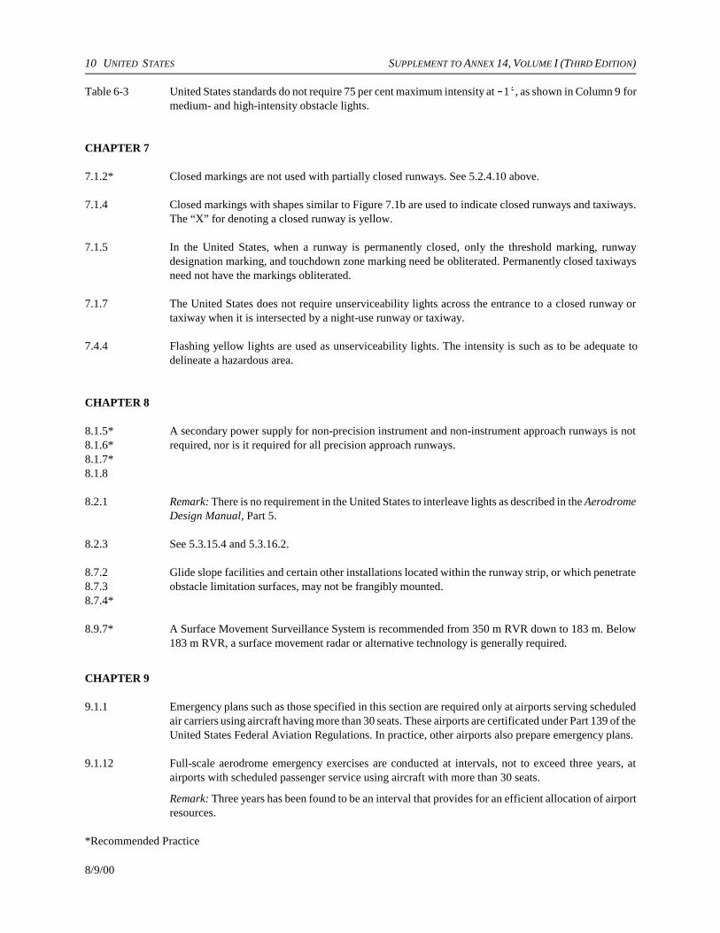
10 UNITED STATES SUPPLEMENT TO ANNEX 14, VOLUME I (THIRD EDITION)
8/9/00
Table 6-3 United States standards do not require 75 per cent maximum intensity at !1E, as shown in Column 9 formedium- and high-intensity obstacle lights.
CHAPTER 7
7.1.2* Closed markings are not used with partially closed runways. See 5.2.4.10 above.
7.1.4 Closed markings with shapes similar to Figure 7.1b are used to indicate closed runways and taxiways.The “X” for denoting a closed runway is yellow.
7.1.5 In the United States, when a runway is permanently closed, only the threshold marking, runwaydesignation marking, and touchdown zone marking need be obliterated. Permanently closed taxiwaysneed not have the markings obliterated.
7.1.7 The United States does not require unserviceability lights across the entrance to a closed runway ortaxiway when it is intersected by a night-use runway or taxiway.
7.4.4 Flashing yellow lights are used as unserviceability lights. The intensity is such as to be adequate todelineate a hazardous area.
CHAPTER 8
8.1.5*8.1.6*8.1.7*8.1.8
A secondary power supply for non-precision instrument and non-instrument approach runways is notrequired, nor is it required for all precision approach runways.
8.2.1 Remark: There is no requirement in the United States to interleave lights as described in the AerodromeDesign Manual, Part 5.
8.2.3 See 5.3.15.4 and 5.3.16.2.
8.7.28.7.38.7.4*
Glide slope facilities and certain other installations located within the runway strip, or which penetrateobstacle limitation surfaces, may not be frangibly mounted.
8.9.7* A Surface Movement Surveillance System is recommended from 350 m RVR down to 183 m. Below183 m RVR, a surface movement radar or alternative technology is generally required.
CHAPTER 9
9.1.1 Emergency plans such as those specified in this section are required only at airports serving scheduledair carriers using aircraft having more than 30 seats. These airports are certificated under Part 139 of theUnited States Federal Aviation Regulations. In practice, other airports also prepare emergency plans.
9.1.12 Full-scale aerodrome emergency exercises are conducted at intervals, not to exceed three years, atairports with scheduled passenger service using aircraft with more than 30 seats.
Remark: Three years has been found to be an interval that provides for an efficient allocation of airportresources.
*Recommended Practice

SUPPLEMENT TO ANNEX 14, VOLUME I (THIRD EDITION) UNITED STATES 11
8/9/00
9.2.1 Rescue and fire fighting equipment and services such as those specified in this section are required onlyat airports serving scheduled air carriers with aircraft having more than 30 seats. Such airports generallyequate to ICAO categories 4 through 9.
9.2.3* There is no plan to eliminate, after 1 January 2005, the current practice of permitting a reduction of onecategory in the Index when the largest aircraft has fewer than an average of five scheduled departuresa day. The reduction in category is a rudimentary cost/benefit consideration and also facilitates theintroduction of large aircraft into scheduled service by not making the air carrier’s planning contingenton the airport’s immediate acquisition of additional equipment.
9.2.49.2.5
The level of protection at United States airports is derived from the length of the largest aircraft servingthe airport. This is similar to the Annex 14 procedure, except that maximum fuselage width is not used.
Remark: United States indices A-E are close equivalents of the Annex’s categories 5-9. The UnitedStates does not have an equivalent to Category 10. The United States will consider the requirements ofCategory 10 when it adopts a new index for very large aircraft. Further harmonization with the Annexwill be considered in the future.
9.2.10 The required fire fighting equipment and agents by index are shown in Table 4.
The substitution equivalencies between complementary agents and foam meeting performance level Aare also used for protein and fluoroprotein foam. Equivalencies for foam meeting performance level Bare used only for aqueous film forming foams.
9.2.18*9.2.19*
At least one apparatus must arrive and apply foam within 3 minutes, with all other required vehiclesarriving within 4 minutes. Response time is measured from the alarm at the equipment’s customaryassigned post, to the commencement of the application of foam at the mid-point of the farthest runway.
Remark: The United States values a rapid response and the presence of professional fire fighters at theearliest possible time to deal with incipient conditions.
9.2.29* For ICAO Category 6 (U.S. index B) the United States allows one vehicle.
9.4.5 At the present time, there is no requirement to perform tests using a continuous friction measuringdevice with self-wetting features. Some United States airports own these devices, while others use lessformal methods to monitor build-up of rubber deposits and the deterioration of friction characteristics.
Remark: The United States is working toward making these devices a requirement, at least at largerairports.
9.4.16 The standard grade for temporary ramps is 15 feet longitudinal per 1 inch of height (0.56 per cent slope)maximum, regardless of overlay depth.
9.4.20 There is no United States standard for declaring a light unserviceable if its intensity is less than 50 percent of the specified or design value of the main beam average intensity.
*Recommended Practice

12 UNITED STATES SUPPLEMENT TO ANNEX 14, VOLUME I (THIRD EDITION)
8/9/00
Table 1. Minimum separations between runway centre line and parallel taxiway/taxilane centre line
OperationAircraftapproachcategory
Aeroplane design group
I1 I II III IV V VI
Visual runways and runways withnot lower than ¾-statute mile(1 200 m) approach visibilityminimums
A&B 150 ft45 m
225 ft67.5 m
240 ft72 m
300 ft90 m
400 ft120 m
– –
Runways with lower than ¾-statutemile (1 200 m) approach visibilityminimums
A&B 200 ft60 m
250 ft75 m
300 ft90 m
350 ft105 m
400 ft120 m
– –
Visual runways and runways withnot lower than ¾-statute mile(1 200 m) approach visibilityminimums
C&D – 300 ft90 m
300 ft90 m
400 ft120 m
400 ft120 m
4002 ft1202 m
600 ft180 m
Runways with lower than ¾-statutemile (1 200 m) approach visibilityminimums
C&D – 400 ft120 m
400 ft120 m
400 ft120 m
400 ft120 m
4002 ft1202 m
600 ft180 m
1 Pertains to small (less than 5 700 kg) aeroplanes.
2 Corrections are made for altitude: 120 m separation for airports at or below 410 m; 135 m for altitudes between 410 mand 2 000 m; and 150 m for altitudes above 2 000 m.
Table 2. Minimum taxiway and taxilane separations
Aeroplane design group
I II III IV V VI
Taxiway centre line to: Parallel taxiway/ taxilane centre line
69 ft21 m
105 ft32 m
152 ft46.5 m
215 ft65.5 m
267 ft81 m
324 ft99 m
Fixed or movable object 44.5 ft13.5 m
65.5 ft20 m
93 ft28.5 m
129.5 ft39.5 m
160 ft48 m
193 ft59 m
Taxiway centre line to: Parallel taxilane centre line 64 ft
19.5 m97 ft
29.5 m140 ft42.5 m
198 ft60 m
245 ft74.5 m
298 ft91 m
Fixed or movable object 39.5 ft12 m
57.5 ft17.5 m
81 ft24.5 m
112.5 ft24.5 m
138 ft42 m
167 ft51 m

SUPPLEMENT TO ANNEX 14, VOLUME I (THIRD EDITION) UNITED STATES 13
8/9/00
Table 3. Dimensions and slopes for protective areas and surfaces
Type ofapproachprocedure
Precisionapproach Non-precision instrument approach Visual runway
All runways All runwaysaRunways other
than utilitybUtility
runwaysdRunways other
than utilityUtility
runways
Width of inneredge 305 m 305 m 152 m 152 m 152 m 76 mc
Divergency(each side) 15 per cent 15 per cent 15 per cent 15 per cent 10 per cent 10 per cent
Final width 4 877 m 1 219 m 1 067 mc 610 m 475 mc 381 mc
Length 15 240 m 3 048 mc 3 048 mc 1 524 mc 1 524 mc 1 524 mc
Slope: inner3 049 m 2 per cent 2.94 per centc 2.94 per centc 5 per centc 5 per centc 5 per centc
Slope: beyond3 048m 2.5 per centc
a With visibility minimum as low as 1.2 km.b With visibility minimum greater than 1.2 km.c Criteria less demanding than Table 4-1 dimensions and slopes.d Utility runways are intended to serve propeller driven aircraft having a maximum take-off mass of 5 670 kg.
Table 4. Fire extinguishing agents and equipment
Index Aircraft length Total minimum quantities ofextinguishing agents
More than Not morethan
Dry chemical
Water forprotein foam
Minimum number oftrucks
Dischargerate 1
A 27 m 225 kg 0 1 See below
B 27 m 38 m 225 kg 5 700 L 1 See below
C 38 m 48 m 225 kg 5 700 L 2 See below
D 48 m 60 m 225 kg 5 700 L 3 See below
E 60 m 225 kg 11 400 L 3 See below
1 Truck size1 900 L but less than 7 600 L:7 600 L or greater:
Discharge rate (Litres per minute):at least 1 900 but not more than 3 800.at least 2 280 but not more than 4 560.

INTERNATIONAL STANDARDSAND RECOMMENDED PRACTICES
AERODROMES
ANNEX 14
TO THE CONVENTION ON INTERNATIONAL CIVIL AVIATION
VOLUME IIHELIPORTS
SECOND EDITION — JULY 1995
This edition incorporates all amendments to Annex 14, Volume II, adoptedby the Council prior to 14 March 1995 and supersedes on
9 November 1995 all previous editions of Annex 14, Volume II.
For information regarding the applicability of the Standards andRecommended Practices, see Foreword and the relevant clauses in
each Chapter
INTERNATIONAL CIVIL AVIATION ORGANIZATION

AMENDMENTS
The issue of amendments is announced regularly in the ICAO Journal and in themonthly Supplement to the Catalogue of ICAO Publications and Audio-visualTraining Aids, which holders of this publication should consult. The space belowis provided to keep a record of such amendments.
RECORD OF AMENDMENTS AND CORRIGENDA
AMENDMENTS CORRIGENDA
No.Date
applicableDate
enteredEntered
by No.Date
of issueDate
enteredEntered
by
1 Incorporated in this edition 20/10/95
2 6/11/97
9/11/95 (ii)

0
1010101
111
122
122333
30
300
300
1
2
224555566
383889925
6
67
TABLE OF CONTENTS
Page Page
Abbreviations and symbols; manuals. . . . . . . . . . . . . . . (v)
FOREWORD . . . . . . . . . . . . . . . . . . . . . . . . . . . . . . . . . (vii)
CHAPTER 1. General . . . . . . . . . . . . . . . . . . . . . . . . . 1
1.1 Definitions . . . . . . . . . . . . . . . . . . . . . . . . . . . . . 11.2 Applicability . . . . . . . . . . . . . . . . . . . . . . . . . . . . 2
CHAPTER 2. Heliport data . . . . . . . . . . . . . . . . . . . . . 3
2.1 Aeronautical data . . . . . . . . . . . . . . . . . . . . . . . . 32.2 Heliport reference point . . . . . . . . . . . . . . . . . . . 32.3 Heliport elevation. . . . . . . . . . . . . . . . . . . . . . . . 42.4 Heliport dimensions and related information . . 42.5 Declared distances . . . . . . . . . . . . . . . . . . . . . . . 42.6 Co-ordination between aeronautical
information services and heliport authorities . . 4
CHAPTER 3. Physical characteristics . . . . . . . . . . . . 5
3.1 Surface-level heliports . . . . . . . . . . . . . . . . . . . . 5— Final approach and take-off areas . . . . . . . . 5— Helicopter clearways. . . . . . . . . . . . . . . . . . . 5— Touchdown and lift-off areas . . . . . . . . . . . . 5— Safety areas . . . . . . . . . . . . . . . . . . . . . . . . . . 6— Helicopter ground taxiways . . . . . . . . . . . . . 6— Air taxiways . . . . . . . . . . . . . . . . . . . . . . . . . 7— Air transit route. . . . . . . . . . . . . . . . . . . . . . . 7— Aprons . . . . . . . . . . . . . . . . . . . . . . . . . . . . . . 7— Location of a final approach and take-off
area in relation to a runway or taxiway . . . . 8
3.2 Elevated heliports. . . . . . . . . . . . . . . . . . . . . . . . 8— Final approach and take-off area and
touchdown and lift-off area . . . . . . . . . . . . . 8— Safety area. . . . . . . . . . . . . . . . . . . . . . . . . . . 8
3.3 Helidecks . . . . . . . . . . . . . . . . . . . . . . . . . . . . . . 9— Final approach and take-off area and
touchdown and lift-off area . . . . . . . . . . . . . 9
3.4 Shipboard heliports . . . . . . . . . . . . . . . . . . . . . . 9— Final approach and take-off area and
touchdown and lift-off area . . . . . . . . . . . . . 9
CHAPTER 4. Obstacle restriction and removal . . . . . 1
4.1 Obstacle limitation surfaces and sectors . . . . . . — Approach surface . . . . . . . . . . . . . . . . . . . . . . — Transitional surface . . . . . . . . . . . . . . . . . . . . — Inner horizontal surface . . . . . . . . . . . . . . . . . 1— Conical surface . . . . . . . . . . . . . . . . . . . . . . . — Take-off climb surface. . . . . . . . . . . . . . . . . . 1— Obstacle-free sector/surface — helidecks . . . — Limited obstacle surface — helidecks . . . . . 1
4.2 Obstacle limitation requirements . . . . . . . . . . . . — Surface level heliports . . . . . . . . . . . . . . . . . . 1— Elevated heliports . . . . . . . . . . . . . . . . . . . . . 1— Helidecks . . . . . . . . . . . . . . . . . . . . . . . . . . . . 1— Shipboard heliports . . . . . . . . . . . . . . . . . . . . 1
CHAPTER 5. Visual aids. . . . . . . . . . . . . . . . . . . . . . .
5.1 Indicators. . . . . . . . . . . . . . . . . . . . . . . . . . . . . . . 5.1.1 Wind direction indicators. . . . . . . . . . . . 3
5.2 Markings and markers . . . . . . . . . . . . . . . . . . . . 5.2.1 Winching area marking . . . . . . . . . . . . . 35.2.2 Heliport identification marking . . . . . . . 305.2.3 Maximum allowable mass marking. . . . 35.2.4 Final approach and take-off area
marking or marker . . . . . . . . . . . . . . . . . 35.2.5 Final approach and take-off area
designation marking . . . . . . . . . . . . . . . . 35.2.6 Aiming point marking . . . . . . . . . . . . . . 35.2.7 Touchdown and lift-off area marking . . 35.2.8 Touchdown marking . . . . . . . . . . . . . . . 35.2.9 Heliport name marking . . . . . . . . . . . . . 35.2.10 Helideck obstacle-free sector marking . 35.2.11 Marking for taxiways. . . . . . . . . . . . . . . 35.2.12 Air taxiway markers. . . . . . . . . . . . . . . . 35.2.13 Air transit route markers . . . . . . . . . . . . 3
5.3 Lights. . . . . . . . . . . . . . . . . . . . . . . . . . . . . . . . . . 5.3.1 General . . . . . . . . . . . . . . . . . . . . . . . . . . 5.3.2 Heliport beacon . . . . . . . . . . . . . . . . . . . 35.3.3 Approach lighting system . . . . . . . . . . . 35.3.4 Visual alignment guidance system . . . . 35.3.5 Visual approach slope indicator. . . . . . . 45.3.6 Final approach and take-off area lights. 45.3.7 Aiming point lights . . . . . . . . . . . . . . . . 45.3.8 Touchdown and lift-off area
lighting system . . . . . . . . . . . . . . . . . . . . 45.3.9 Winching area floodlighting . . . . . . . . . 4
ANNEX 14 — VOLUME II (iii) 9/11/956/11/97No. 2

Annex 14 — Aerodromes Volume II
Page Page
995050
51
5.3.10 Taxiway lights . . . . . . . . . . . . . . . . . . . . 475.3.11 Visual aids for denoting obstacles . . . . 475.3.12 Floodlighting of obstacles . . . . . . . . . . . 47
CHAPTER 6. Heliport services. . . . . . . . . . . . . . . . . . 49
6.1 Rescue and fire fighting. . . . . . . . . . . . . . . . . . . 49— General . . . . . . . . . . . . . . . . . . . . . . . . . . . . . 49
— Level of protection to be provided . . . . . . . . 4— Extinguishing agents . . . . . . . . . . . . . . . . . . . 4— Rescue equipment . . . . . . . . . . . . . . . . . . . . . — Response time . . . . . . . . . . . . . . . . . . . . . . . .
APPENDIX 1. Aeronautical data quality requirements . . . . . . . . . . . . . . . . . . . . . . . . . . . .
9/11/95 (iv)6/11/97No. 2

ANNEX 14 — VOLUME II (v) 9/11/95
ABBREVIATIONS AND SYMBOLS(used in Annex 14, Volume II)
Abbreviations Abbreviations
cd Candelacm CentimeterD Helicopter largest over-all dimensionFATO Final approach and take-off areaft FootHAPI Helicopter approach path indicatorHz HertzIMC Instrument meteorological conditionskg Kilogramkm/h Kilometre per hourkt KnotL LitreLDAH Landing distance availableL/min Litre per minutem Metre
RD Diameter of the largest rotorRTODAH Rejected take-off distance availables SecondTLOF Touchdown and lift-off areaTODAH Take-off distance availableVMC Visual meteorological conditions
Symbols
° Degree= Equals% Percentage± Plus or minus
MANUALS(related to the specifications of this Annex)
Aerodrome Design Manual (Doc 9157)Part 1 — RunwaysPart 2 — Taxiways, Aprons and Holding BaysPart 3 — PavementsPart 4 — Visual AidsPart 5 — Electrical Systems
Airport Planning Manual (Doc 9184)Part 1 — Master PlanningPart 2 — Land Use and Environmental ControlPart 3 — Guidelines for Consultant/Construction Services
Airport Services Manual (Doc 9137)Part 1 — Rescue and Fire FightingPart 2 — Pavement Surface ConditionsPart 3 — Bird Control and Reduction
Part 4 — Fog Dispersal (withdrawn)Part 5 — Removal of Disabled AircraftPart 6 — Control of ObstaclesPart 7 — Airport Emergency PlanningPart 8 — Airport Operational ServicesPart 9 — Airport Maintenance Practices
Heliport Manual (Doc 9261)
Stolport Manual (Doc 9150)
Manual on the ICAO Bird Strike Information System (IBIS)(Doc 9332)
Manual of Surface Movement Guidance and Control Systems (SMGCS) (Doc 9476)

f
ro-ce
d ince
otx;
n.
e,ofor
hhf
l,m
he-gth
lys
he
dlf-
FOREWORD
Historical background
Standards and Recommended Practices for aerodromes werefirst adopted by the Council on 29 May 1951 pursuant to theprovisions of Article 37 of the Convention on InternationalCivil Aviation (Chicago 1944) and designated as Annex 14 tothe Convention. The document containing these Standards andRecommended Practices is now designated as Annex 14,Volume I to the Convention. In general, Volume I addressesplanning, design and operations of aerodromes but is notspecifically applicable to heliports.
Therefore, Volume II is being introduced as a means ofincluding provisions for heliports. Proposals forcomprehensive Standards and Recommended Practicescovering all aspects of heliport planning, design andoperations have been developed with the assistance of theANC Visual Aids Panel and the ANC Helicopter OperationsPanel.
Table A shows the origin of the provisions in this volume,together with a list of the principal subjects involved and thedates on which the Annex was adopted by the Council, whenit became effective and when it became applicable.
Action by Contracting States
Notification of differences. The attention of Contracting Statesis drawn to the obligation imposed by Article 38 of theConvention by which Contracting States are required to notifythe Organization of any differences between their nationalregulations and practices and the International Standardscontained in this Annex and any amendments thereto.Contracting States are invited to extend such notification toany differences from Recommended Practices contained inthis Annex and any amendments thereto, when the notificationof such differences is important for the safety of airnavigation. Further, Contracting States are invited to keep theOrganization currently informed of any differences which maysubsequently occur, or of the withdrawal of any differencespreviously notified. A specified request for notification ofdifferences will be sent to Contracting States immediately afterthe adoption of each amendment to this Annex.
The attention of States is also drawn to the provisions ofAnnex 15 related to the publication of differences betweentheir national regulations and practices and the related ICAOStandards and Recommended Practices through the Aero-
nautical Information Service, in addition to the obligation oStates under Article 38 of the Convention.
Promulgation of information. The establishment andwithdrawal of and changes to facilities, services and pcedures affecting aircraft operations provided in accordanwith the Standards and Recommended Practices specifiethis Annex should be notified and take effect in accordanwith the provisions of Annex 15.
Status of Annex components
An Annex is made up of the following component parts, nall of which, however, are necessarily found in every Annethey have the status indicated:
1. — Material comprising the Annex proper:
a) Standards and Recommended Practices adopted bythe Council under the provisions of the ConventioThey are defined as follows:
Standard: Any specification for physicalcharacteristics, configuration, matériel, performancpersonnel or procedure, the uniform application which is recognized as necessary for the safety regularity of international air navigation and to whicContracting States will conform in accordance witthe Convention; in the event of impossibility ocompliance, notification to the Council iscompulsory under Article 38.
Recommended Practice: Any specification forphysical characteristics, configuration, matérieperformance, personnel or procedure, the uniforapplication of which is recognized as desirable in tinterest of safety, regularity or efficiency of international air navigation, and to which ContractinStates will endeavour to conform in accordance withe Convention.
b) Appendices comprising material grouped separatefor convenience but forming part of the Standardand Recommended Practices adopted by tCouncil.
c) Definitions of terms used in the Standards anRecommended Practices which are not se
ANNEX 14 — VOLUME II (vii) 9/11/95

Annex 14 — Aerodromes Volume II
ish, is ofinghhe
ate
by
erbtive
inasilvenits. thatay,is
isof
explanatory in that they do not have accepteddictionary meanings. A definition does not haveindependent status but is an essential part of eachStandard and Recommended Practice in which theterm is used, since a change in the meaning of theterm would affect the specifications.
d) Tables and Figures which add to or illustrate aStandard or Recommended Practice and which arereferred to therein, form part of the associatedStandard or Recommended Practice and have thesame status.
2.— Material approved by the Council for publication inassociation with the Standards and Recommended Practices:
a) Forewords comprising historical and explanatorymaterial based on the action of the Council andincluding an explanation of the obligations of Stateswith regard to the application of the Standards andRecommended Practices ensuing from theConvention and the Resolution of Adoption.
b) Introductions comprising explanatory materialintroduced at the beginning of parts, chapters orsections of the Annex to assist in the understandingof the application of the text.
c) Notes included in the text, where appropriate, to givefactual information or references bearing on theStandards or Recommended Practices in question,but not constituting part of the Standards orRecommended Practices.
d) Attachments comprising material supplementary tothe Standards and Recommended Practices, orincluded as a guide to their application.
Selection of language
This Annex has been adopted in four languages — EnglFrench, Russian and Spanish. Each Contracting Staterequested to select one of those texts for the purposenational implementation and for other effects provided for the Convention, either through direct use or throutranslation into its own national language, and to notify tOrganization accordingly.
Editorial practices
The following practice has been adhered to in order to indicat a glance the status of each statement: Standards have beenprinted in light face roman; Recommended Practices havebeen printed in light face italics, the status being indicatedthe prefix Recommendation; Notes have been printed in lightface italics, the status being indicated by the prefix Note.
The following editorial practice has been followed in thwriting of specifications: for Standards the operative ve“shall” is used, and for Recommended Practices the operaverb “should’’ is used.
The units of measurement used in this document areaccordance with the International System of Units (SI) specified in Annex 5 to the Convention on International CivAviation. Where Annex 5 permits the use of non-SI alternatiunits these are shown in parentheses following the basic uWhere two sets of units are quoted it must not be assumedthe pairs of values are equal and interchangeable. It mhowever, be inferred that an equivalent level of safety achieved when either set of units is used exclusively.
Any reference to a portion of this document, which identified by a number and/or title, includes all subdivisions that portion.
9/11/95 (viii)

Foreword Annex 14 — Aerodromes
(ix) 9/11/95
Table A. Amendments to Annex 14, Volume II
Amendment Source(s) Subject(s)
AdoptedEffective
Applicable
1st Edition Fourth Meeting of the ANC Helicopter Operations Panel; Eleventh meeting of the ANC Visual Aids Panel and Secretariat
Physical characteristics; obstacle limitation surfaces; visual aids for visual meteorological conditions; rescue and fire fighting services.
9 March 199030 July 190015 November 1990
1 (2nd Edition)
Twelfth Meeting of the ANC Visual Aids Panel and Secretariat
Standard geodetic reference system (WGS-84); frangibility; visual aids for helicopter non-precision approaches; and visual alignment guidance system.
13 March 199524 July 19959 November 1995
2 Air NavigationCommission
Aeronautical data bases and vertical component of the World Geodetic System — 1984 (WGS-84).
21 March 199721 July 19976 November 1997
6/11/97No. 2

tarms
ofd
ed1
reatoht.
n
ter
toff
sedrea
oem
evel
al.)at
INTERNATIONAL STANDARDSAND RECOMMENDED PRACTICES
CHAPTER 1. GENERAL
Introductory Note.— Volume II of this Annex containsStandards and Recommended Practices (specifications) thatprescribe the physical characteristics and obstacle limitationsurfaces to be provided for at heliports, and certain facilitiesand technical services normally provided at a heliport. It isnot intended that these specifications limit or regulate theoperation of an aircraft.
The specifications in this volume modify or complementthose in Volume I which, where appropriate, are alsoapplicable to heliports. In other words, where a particularissue is a subject of a specification in this volume thatspecification will supersede any other specification on thatparticular issue in Volume I. Throughout this volume the term“heliport” is used; however, it is intended that thesespecifications also apply to areas for the exclusive use ofhelicopters at an aerodrome primarily meant for the use ofaeroplanes.
It is to be noted that provisions for helicopter flightoperations are contained in Annex 6, Part III.
1.1 Definitions
When the following terms are used in this volume they havethe meanings given below. Annex 14, Volume I containsdefinitions for those terms which are used in both volumes.
Accuracy. A degree of conformance between the estimated ormeasured value and the true value.
Note.— For measured positional data the accuracy isnormally expressed in terms of a distance from a statedposition within which there is a defined confidence of the trueposition falling.
Air taxiway. A defined path on the surface established for theair taxiing of helicopters.
Air transit route. A defined path on the surface established forthe air transitting of helicopters.
Cyclic redundancy check (CRC). A mathematical algorithmapplied to the digital expression of data that provides alevel of assurance against loss or alteration of data.
Data quality. A degree or level of confidence that the daprovided meets the requirements of the data user in teof accuracy, resolution and integrity.
Declared distances — heliports.
a) Take-off distance available (TODAH). The length of thefinal approach and take-off area plus the length helicopter clearway (if provided) declared available ansuitable for helicopters to complete the take-off.
b) Rejected take-off distance available (RTODAH). Thelength of the final approach and take-off area declaravailable and suitable for performance class helicopters to complete a rejected take-off.
c) Landing distance available (LDAH). The length of thefinal approach and take-off area plus any additional adeclared available and suitable for helicopters complete the landing manoeuvre from a defined heig
Elevated heliport. A heliport located on a raised structure oland.
Ellipsoid height (Geodetic height). The height related to thereference ellipsoid, measured along the ellipsoidal ounormal through the point in question.
Final approach and take-off area (FATO). A defined areaover which the final phase of the approach manoeuvrehover or landing is completed and from which the take-omanoeuvre is commenced. Where the FATO is to be uby performance Class 1 helicopters, the defined aincludes the rejected take-off area available.
Geodetic datum. A minimum set of parameters required tdefine location and orientation of the local reference systwith respect to the global reference system/frame.
Geoid. The equipotential surface in the gravity field of thEarth which coincides with the undisturbed mean sea le(MSL) extended continuously through the continents.
Note.— The geoid is irregular in shape because of locgravitational disturbances (wind tides, salinity, current, etcand the direction of gravity is perpendicular to the geoid every point.
ANNEX 14 — VOLUME II 1 9/11/956/11/97No. 2

Annex 14 — Aerodromes Volume II
riskhe
othe
intheheionits
orith
ll in,
as
e,o
Geoid undulation. The distance of the geoid above (positive)or below (negative) the mathematical reference ellipsoid.
Note.— In respect to the World Geodetic System — 1984(WGS-84) defined ellipsoid, the difference between the WGS-84 ellipsoidal height and orthometric height representsWGS-84 geoid undulation.
Helicopter ground taxiway. A ground taxiway for use byhelicopters only.
Helicopter clearway. A defined area on the ground or waterunder the control of the appropriate authority, selected and/or prepared as a suitable area over which a performanceclass 1 helicopter may accelerate and achieve a specificheight.
Helicopter stand. An aircraft stand which provides for parkinga helicopter and, where air taxiing operations arecontemplated, the helicopter touchdown and lift-off.
Helideck. A heliport located on a floating or fixed off-shorestructure.
Heliport. An aerodrome or a defined area on a structureintended to be used wholly or in part for the arrival,departure and surface movement of helicopters.
Integrity (aeronautical data). A degree of assurance that anaeronautical data and its value has not been lost nor alteredsince the data origination or authorized amendment.
Orthometric height. Height of a point related to the geoid,generally presented as an MSL elevation.
Safety area. A defined area on a heliport surrounding theFATO which is free of obstacles, other than those required
for air navigation purposes, and intended to reduce the of damage to helicopters accidentally diverging from tFATO.
Station declination. An alignment variation between the zerdegree radial of a VOR and true north, determined at time the VOR station is calibrated.
Surface level heliport. A heliport located on the ground or onthe water.
Touchdown and lift-off area (TLOF). A load bearing area onwhich a helicopter may touch down or lift off.
1.2 Applicability
1.2.1 The interpretation of some of the specifications the Annex expressly requires the exercising of discretion, taking of a decision or the performance of a function by tappropriate authority. In other specifications, the expressappropriate authority does not actually appear although inclusion is implied. In both cases, the responsibility fwhatever determination or action is necessary shall rest wthe State having jurisdiction over the heliport.
1.2.2 The specifications in Annex 14, Volume II shaapply to all heliports intended to be used by helicoptersinternational civil aviation. The specifications of Annex 14Volume I shall apply, where appropriate, to these heliportswell.
1.2.3 Wherever a colour is referred to in this volumthe specifications for that colour given in Appendix 1 tAnnex 14, Volume I shall apply.
9/11/95 26/11/97No. 2
ityd
cyAild
ndticalticm,en
ansthe
ethehbles
seats,ornedity.
chith
S-15,
r a
e,oth
arall
CHAPTER 2. HELIPORT DATA
2.1 Aeronautical data
2.1.1 Determination and reporting of heliport relatedaeronautical data shall be in accordance with the accuracy andintegrity requirements set forth in Tables 1 to 5 contained inAppendix 1 while taking into account the established qualitysystem procedures. Accuracy requirements for aeronauticaldata are based upon a 95 per cent confidence level and in thatrespect, three types of positional data shall be identified:surveyed points (e.g. FATO threshold), calculated points(mathematical calculations from the known surveyed points ofpoints in space, fixes) and declared points (e.g. flightinformation region boundary points).
Note. — Specifications governing the quality system aregiven in Annex 15, Chapter 3.
2.1.2 Contracting States shall ensure that integrity ofaeronautical data is maintained throughout the data processfrom survey/origin to the next intended user. Aeronautical dataintegrity requirements shall be based upon the potential riskresulting from the corruption of data and upon the use towhich the data item is put. Consequently, the followingclassification and data integrity level shall apply:
a) critical data, integrity level 1 × 10⁻⁸: there is a highprobability when using corrupted critical data that thecontinued safe flight and landing of an aircraft would beseverely at risk with the potential for catastrophe;
b) essential data, integrity level 1 × 10⁻⁵: there is a lowprobability when using corrupted essential data that thecontinued safe flight and landing of an aircraft would beseverely at risk with the potential for catastrophe; and
c) routine data, integrity level 1 × 10⁻³: there is a very lowprobability when using corrupted routine data that thecontinued safe flight and landing of an aircraft would beseverely at risk with the potential for catastrophe.
2.1.3 Protection of electronic aeronautical data whilestored or in transit shall be totally monitored by the cyclicredundancy check (CRC). To achieve protection of theintegrity level of critical and essential aeronautical data asclassified in 2.1.2 above, a 32 or 24 bit CRC algorithm shallapply respectively.
2.1.4 Recommendation. — To achieve protection of theintegrity level of routine aeronautical data as classified in 2.1.2above, a 16 bit CRC algorithm should apply.
Note.— Guidance material on the aeronautical data qualrequirements (accuracy, resolution, integrity, protection antraceability) is contained in the World Geodetic System —1984 (WGS-84) Manual (Doc 9674). Supporting material inrespect of the provisions of Appendix 1 related to accuraand integrity of aeronautical data, is contained in RTCDocument DO-201A and European Organization for CivAviation Equipment (EUROCAE) Document ED-77, entitle“Industry Requirements for Aeronautical Information”.
2.1.5 Geographical coordinates indicating latitude alongitude shall be determined and reported to the aeronauinformation services authority in terms of the World GeodeSystem — 1984 (WGS-84) geodetic reference datuidentifying those geographical coordinates which have betransformed into WGS-84 coordinates by mathematical meand whose accuracy of original field work does not meet requirements in Appendix 1, Table 1.
2.1.6 The order of accuracy of the field work shall bsuch that the resulting operational navigation data for phases of flight will be within the maximum deviations, witrespect to an appropriate reference frame, as indicated in tacontained in Appendix 1.
2.1.7 In addition to the elevation (referenced to mean level) of the specific surveyed ground positions at heliporgeoid undulation (referenced to the WGS-84 ellipsoid) fthose positions as indicated in Appendix 1, shall be determiand reported to the aeronautical information services author
Note 1.— An appropriate reference frame is that whienables WGS-84 to be realized on a given heliport and wrespect to which all coordinate data are related.
Note 2.— Specifications governing the publication of WG84 coordinates are given in Annex 4, Chapter 2 and Annex Chapter 3.
2.2 Heliport reference point
2.2.1 A heliport reference point shall be established foheliport not co-located with an aerodrome.
Note.— When the heliport is co-located with an aerodromthe established aerodrome reference point serves baerodrome and heliport.
2.2.2 The heliport reference point shall be located nethe initial or planned geometric centre of the heliport and shnormally remain where first established.
ANNEX 14 — VOLUME II 3 9/11/95ANNEX 14 — VOLUME II 3 9/11/956/11/97No. 2

Annex 14 — Aerodromes Volume II
e
ricchretical
nds
treairthes,
terticalnds
ntredrity. In ortion
be
estetticalforcal
es
2.2.3 The position of the heliport reference point shall bemeasured and reported to the aeronautical information servicesauthority in degrees, minutes and seconds.
2.3 Heliport elevation
2.3.1 The heliport elevation and geoid undulation at theheliport elevation position shall be measured and reported tothe aeronautical information services authority to the accuracyof one-half metre or foot.
2.3.2 For a heliport used by international civil aviation,the elevation of the touchdown and lift-off area and/or theelevation and geoid undulation of each threshold of the finalapproach and take-off area (where appropriate) shall bemeasured and reported to the aeronautical information servicesauthority to the accuracy of:
— one-half metre or foot for non-precision approaches; and
— one-quarter metre or foot for precision approaches.
Note.— Geoid undulation must be measured in accordancewith the appropriate system of coordinates.
2.4 Heliport dimensions and related information
2.4.1 The following data shall be measured or described,as appropriate, for each facility provided on a heliport:
a) heliport type — surface-level, elevated or helideck;
b) touchdown and lift-off area — dimensions to the nearestmetre or foot, slope, surface type, bearing strength intonnes (1 000 kg);
c) final approach and take-off area — type of FATO, truebearing to one-hundredth of a degree, designationnumber (where appropriate), length, width to the nearestmetre or foot, slope, surface type;
d) safety area — length, width and surface type;
e) helicopter ground taxiway, air taxiway and air transitroute — designation, width, surface type;
f) apron — surface type, helicopter stands;
g) clearway — length, ground profile; and
h) visual aids for approach procedures, marking andlighting of FATO, TLOF, taxiways and aprons.
i) distances to the nearest metre or foot of localizer andglide path elements comprising an instrument landingsystem (ILS) or azimuth and elevation antenna of
microwave landing system (MLS) in relation to thassociated TLOF or FATO extremities.
2.4.2 The geographical coordinates of the geometcentre of the touchdown and lift-off area and/or of eathreshold of the final approach and take-off area (wheappropriate) shall be measured and reported to the aeronauinformation services authority in degrees, minutes, secoand hundredths of seconds.
2.4.3 The geographical coordinates of appropriate cenline points of helicopter ground taxiways, air taxiways and transit routes shall be measured and reported to aeronautical information services authority in degreeminutes, seconds and hundredths of seconds.
2.4.4 The geographical coordinates of each helicopstand shall be measured and reported to the aeronauinformation services authority in degrees, minutes, secoand hundredths of seconds.
2.4.5 The geographical coordinates of significaobstacles on and in the vicinity of a heliport shall be measuand reported to the aeronautical information services authoin degrees, minutes, seconds and tenths of secondsaddition, the top elevation rounded up to the nearest metrefoot, type, marking and lighting (if any) of the significanobstacles shall be reported to the aeronautical informatservices authority.
2.5 Declared distances
The following distances to the nearest metre or foot shalldeclared, where relevant, for a heliport:
a) take-off distance available;
b) rejected take-off distance available; and
c) landing distance available.
2.6 Co-ordination between aeronautical informationservices and heliport authorities
2.6.1 To ensure that aeronautical information servicunits obtain information to enable them to provide up-to-dapre-flight information and to meet the need for in-flighinformation, arrangements shall be made between aeronauinformation services and heliport authorities responsible heliport services to report to the responsible aeronautiinformation services unit, with a minimum of delay:
a) information on heliport conditions;
b) the operational status of associated facilities, servicand navigation aids within their area of responsibility;
9/11/95 46/11/97No. 2

Chapter 2 Annex 14 — Aerodromes
ofalnt as
M5,
ISith
nce
er-alsthe
,
c) any other information considered to be of operationalsignificance.
2.6.2 Before introducing changes to the air navigationsystem, due account shall be taken by the services responsiblefor such changes of the time needed by the aeronauticalinformation service for the preparation, production and issueof relevant material for promulgation. To ensure timelyprovision of the information to the aeronautical informationservice, close co-ordination between those services concernedis therefore required.
2.6.3 Of a particular importance are changes toaeronautical information that affect charts and/or computer-based navigation systems which qualify to be notified by theaeronautical information regulation and control (AIRAC)system, as specified in Annex 15, Chapter 6 and Appendix 4.The predetermined, internationally agreed AIRAC effectivedates in addition to 14 days postage time shall be observed bythe responsible heliport services when submitting the rawinformation/data to aeronautical information services.
2.6.4 The heliport services responsible for the provisionraw aeronautical information/data to the aeronauticinformation services shall do that while taking into accouaccuracy and integrity requirements for aeronautical dataspecified in Appendix 1 to this Annex.
Note 1.— Specifications for the issue of a NOTAand SNOWTAM are contained in Annex 15, Chapter Appendices 6 and 2 respectively.
Note 2.— The AIRAC information is distributed by the Aat least 42 days in advance of the AIRAC effective dates wthe objective of reaching recipients at least 28 days in advaof the effective date.
Note 3.— The schedule of the predetermined intnationally agreed AIRAC common effective dates at intervof 28 days, including 6 November 1997 and guidance for AIRAC use are contained in the Aeronautical InformationServices Manual (Doc 8126, Chapter 3, 3.1.1 and Chapter 44.4).
5 9/11/956/11/97No. 2
4A
CHAPTER 3. PHYSICAL CHARACTERISTICS
3.1 Surface-level heliports
Note.- The following specifications are for sutface-level land heliports (except where specijìed).
Final approach and take-off areas
3.1.1 A surface-level heliport shall be provided with at least one FATO.
Note.- A FATO may be located on or near a runway strip or taxiway strip.
3.1.2 The dimensions of a FATO shall be:
for a heliport intended to be used by performance class 1 helicopters, as prescribed in the helicopter flight manual except that, in the absence of width specifications, the width shall be not less than 1.5 times the over-all lengtwwidth, whichever is greater, of the longest/widest helicopter the heliport is intended to serve;
for a water heliport intended to be used by performance class I helicopters, as prescribed in a) above, plus 10 per cent;
for a heliport intended to be used by performance class 2 and 3 helicopters, of sufficient size and shape to contain an area within which can be drawn a circle of diameter not less than 1.5 times the over-all lengthlwidth, whichever is greater, of the longest/widest helicopter the heliport is intended to serve; and
for a water heliport intended to be used by performance class 2 and 3 helicopters, of sufficient size to contain an area within which can be drawn a circle of diameter not less than two times the over-all lengtwwidth, whichever is greater, of the longestlwidest helicopter the heliport is intended to serve.
Note.- Local conditions, such as elevation and temperature, may need to be considered when determining the size of a FATO. Guidance is given in the Heliport Manual.
3.1.3 The over-all slope in any direction on the FATO shall not exceed 3 per cent. No portion of a FATO shall have a local slope exceeding:
a) 5 per cent where the heliport is intended to be used by performance class 1 helicopters; and
ANNEX 14 - VOLUME II 5
b) 7 per cent where the heliport is intended to be used by performance class 2 and 3 helicopters.
3.1.4 The surface of the FATO shall:
a) be resistant to the effects of rotor downwash;
b) be free of irregularities that would adversely affect the take-off or landing of helicopters; and
c) have bearing strength sufficient to accommodate a rejected take-off by performance class 1 helicopters.
3.1.5 Recommendation,- The FATO should provide ground effect.
Helicopter cleanvays
3.1.6 When it is necessary to provide a helicopter clearway, it shall be located beyond the upwind end of the rejected take-off area available.
3.1.7 Recommendation.- The width of a helicopter clearway should not be less than that of rhe associated safety area.
3.1.8 Recommendation.- The ground in a helicopter clearway should not project above a plane having an upward slope of 3 per cent, the lower limit of this plane being a horizontal line which is located on the periphery of the FATO.
3.1.9 Recommendation.- An object situated on a helicopter clearway which may endanger helicopters in the air should be regarded as an obstacle and should be removed.
Touchdown and lifr-off areas
3.1.10 At least one touchdown and lift-off area shall be provided at a heliport.
Note.- The touchdown and lift-off area may or may not be located within the FATO.
3.1.1 I The touchdown and lift-off area (TLOF) shall be of sufficient size to contain a circle of diameter 1.5 times the length or width of the undercarriage, whichever is the greater, of the largest helicopter the area is intended to serve.
Note.- A touchdown and lift-off area may be any shape.
911 1/95
COPYRIGHT International Civil Aviation OrganizationLicensed by Information Handling ServicesCOPYRIGHT International Civil Aviation OrganizationLicensed by Information Handling Services

ICA0 ANNEX*L4 VOLWII ** m 484L4Lb 00bb900 671
Annex 14 - Aerodromes
3.1.12 Slopes on a touchdown and lift-off area shall be sufficient to prevent accumulation of water on the surface of the area, but shall not exceed 2 per cent in any direction.
3.1.13 A touchdown and lift-off area shall be capable of withstanding the traffic of helicopters that the area is intended to serve.
Safety arem
3.1.14 A FATO shall be surrounded by a safety area.
3. l . 15 A safety area surrounding a FATO intended to be used in visual meteorological conditions (VMC) shall extend outwards from the periphery of the FATO for a distance of at least 3 m or 0.25 times the over-all lengthlwidth, whichever is greater, of the 1ongestJwidest helicopter the area is intended to serve.
3.1.16 A safety area surrounding a FATO intended to be used by helicopter operations in instrument meteorological conditions (MC) shall extend:
a) laterally to a distance of at least 45 m on each side of the centre line; and
b) longitudinally to a distance of at least 60 m beyond the ends of the FATO.
Note.- See Figure 3-1.
3.1.17 No fixed object shall be permitted on a safety area, except for frangible objects, which, because of their function, must be located on the area. No mobile object shall be permitted on a safety area during helicopter operations.
3.1.18 Objects whose functions require them to be located on the safety area shall not exceed a height of 25 cm when located along the edge of the FATO nor penetrate a plane originating at a height of 25 cm above the edge of the FATO and sloping upwards and outwards from the edge of the FATO at a gradient of 5 per cent.
3.1.19 The surface of the safety area shall not exceed an upward slope of 4 per cent outwards from the edge of the FATO.
Volume I I
3.1.20 The surface of the safety area shall be treated to prevent flying debris caused by rotor downwash.
3.1.2 1 The surface of the safety area abutting the FATO shall be continuous with the FATO and be capable of supporting, without structural damage, the helicopters that the heliport is intended to serve.
Helicopter ground taxiways
Note.- A helicopter ground taxiway i s intended to permit the surface movement of a wheeled helicopter under its own power. The specflcations for taxiways, taxiway shoulders and taxiway strips included in Annex 14, Volume I are equally applicable to heliports as modified below. When a taxiway is intended for use by aeroplanes and helicopters, the provisions for taxiways and helicopter ground taxiways will be examined and the more stringent requirements will be applied.
3.1.22 The width of a helicopter ground taxiway shall not be less than:
Helicopter main gear span Helicopter ground
taxiway width
Up to but not including 4.5 m 7.5 m
4.5 m up to but not including 6 m 10.5 m
6 m up to but not including 10 m 15 m
10 m and over 20 m
3.1.23 The separation distance between a helicopter ground taxiway and another helicopter ground taxiway, an air taxiway, an object or helicopter stand shall not be less than the appropriate dimension specified in Table 3- l .
3.1.24 The longitudinal slope of a helicopter ground taxiway shall not exceed 3 per cent.
3.1.25 Recommendation.- A helicopter ground taxiway should be capable of withstanding the trafic of helicopters that the helicopter ground taxiway is intended to serve.
I I I Safety area
" 6 0 I m I FATO 7 -6Om- I
I
Helicopter clearway Rejected take-off area I I I I I I I
9/1 U95
Figure 3-1. Safety area for instrument FATO
6
COPYRIGHT International Civil Aviation OrganizationLicensed by Information Handling ServicesCOPYRIGHT International Civil Aviation OrganizationLicensed by Information Handling Services

Chapter 3
3.1.26 Recommendation.- A helicopter ground taxiway should be provided with shoulders which extend symmetrically on each side of the helicopter ground taxiway for at least one- half the greatest over-all width of the helicopters that the helicopter ground taxiway is intended to serve.
3.1.27 The helicopter ground taxiway and its shoulder shall provide rapid drainage but the helicopter ground taxiway transverse slope shall not exceed 2 per cent.
3.1.28 Recommendation.- The sulface of a helicopter ground taxiway shoulder should be resistant to the effect of rotor downwash.
Air taxiways
Note.- An air taxiway is intended to permit the movement of a helicopter above the sulface at a height normally associated with ground effect and at groundspeed less than 37 km/h (20 kt).
3.1.29 The width of an air taxiway shall be at least two times the greatest over-all width of the helicopters that the air taxiway is intended to serve.
3.1.30 The surface of an air taxiway shall:
a) be resistant to the effects of rotor downwash; and
b) be suitable for emergency landings.
3.1.3 1 Recommendation.- The sulface of an air taxiway should provide ground effect.
3.1.32 Recommendation.- The transverse slope of the sulface of an air taxiway should not exceed 10 per cent and the longitudinal slope should not exceed 7 per cent. In any event, the slopes should not exceed the slope landing limitations of the helicopters the air taxiway is intended to serve.
Annex 14 - Aerodromes
3.1.33 The separation distance between an air taxiway and another air taxiway, a helicopter ground taxiway, an object or a helicopter stand shall not be less than the appropriate dimension in Table 3- 1.
Air transit route
Note.- An air transit route is intended to permit the movement of a helicopter above the sulface, n o m l l y at heights not above 30 m (100 ft) above ground level and at ground speeds exceeding 37 km/h (20 kt).
3.1.34 The width of an air transit route shall not be less than:
a) 7.0 times RD when the air transit route is intended for use by day only; and
b) 10.0 times RD when the air transit route is intended for use at night;
when RD is the diameter of the largest rotor of the helicopters that the air transit route is intended to serve.
3.1.35 Any variation in the direction of the centre line of an air transit route shall not exceed 120" and be designed so as not to necessitate a turn of radius less than 270 m.
Note.- It is intended that air transit routes be selected so as to permit autorotative or one-engine-inoperative landings such that, as a minimum requirement, injury to persons on the ground or water, or damage to property are minimized.
Aprons
Note.- The specifications for aprons included in Chapter 3 of Annex 14, Volume I are equally applicable to heliports as modified below.
Table 3-1. Helicopter ground taxiway and air taxiway separation distances (expressed in multiples of greatest over-all width of helicopter with rotor turning)
Helicopter ground Air Helicopter
Facility taxiway taxiway Object stand ~~
Helicopter 2 4 1 ground (between (between (edge to taxiway edges) centre lines) object)
2 (between
edges)
4 4 1 '12 4 Air (between (between (centre line (centre line
taxiway centre lines) centre lines) to object) to edge)
7 911 1/95
COPYRIGHT International Civil Aviation OrganizationLicensed by Information Handling ServicesCOPYRIGHT International Civil Aviation OrganizationLicensed by Information Handling Services
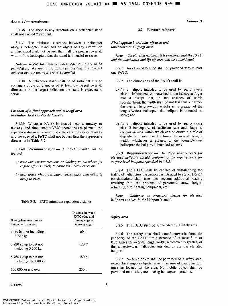
I C A 0 ANNEX+L4 VOLaII X+ 484141b 00hb902 4 4 4 m
Annex 14 -Aerodromes
3.1.36 The slope in any direction on a helicopter stand shall not exceed 2 per cent.
3.1.37 The minimum clearance between a helicopter using a helicopter stand and an object or any aircraft on another stand shall not be less than half the greatest over-all width of the helicopters that the stand is intended to serve.
Note.- Where simultaneous hover operations are to be provided for, the separation distances specified in Table 3-1 between two air taxiways are to be applied.
3.1.38 A helicopter stand shall be of sufficient size to contain a circle of diameter of at least the largest over-all dimension of the largest helicopter the stand is expected to serve.
Location of a final approach and take-off area in relation to a mnway or taxiway
3.1.39 Where a FATO is located near a runway or taxiway, and simultaneous VMC operations are planned, the separation distance between the edge of a runway or taxiway and the edge of a FATO shall not be less than the appropriate dimension in Table 3-2.
3.1.40 Recommendation.- A FATO should not be located:
a) near taxiway intersections or holding points where jet engine efJlux is likely to cause high turbulence; or
b) near areas where aeroplane vortex wake generation is likely to exist.
Table 3-2. FATO minimum separation distance
If aeroplane mass and/or helicopter mass are
Distance between FATO edge and runway edge or taxiway edge
up to but not including 2 720 kg
2 720 kg up to but not including 5 760 kg
5 760 kg up to but not including 1 O0 O 0 0 kg
100 O 0 0 kg and over
60 m
120 m
180 m
250 m
Volume II
3.2 Elevated heliports
Final approach and take-off area and touchdown and lift-off area
Note.- On elevated heliports it is presumed that the FATO and the touchdown and lift-off area will be coincidental.
3.2.1 An elevated heliport shall be provided with at least one FATO.
3.2.2 The dimensions of the FATO shall be:
a) for a heliport intended to be used by performance class 1 helicopters, as prescribed in the helicopter flight manual except that, in the absence of width specifications, the width shall be not less than 1.5 times the over-all lengtwwidth, whichever is greater, of the longestlwidest helicopter the heliport is intended to serve; and
b) for a heliport intended to be used by performance class 2 helicopters, of sufficient size and shape to contain an area within which can be drawn a circle of diameter not less than 1.5 times the over-all lengtN width, whichever is greater, of the longestlwidest helicopter the heliport is intended to serve.
3.2.3 Recommendation- The slope requirements for elevated heliports should conform to the requirements for s u ~ a c e level heliports specified in 3.1.3.
3.2.4 The FATO shall be capable of withstanding the traffic of helicopters the heliport is intended to serve. Design considerations shall take into account additional loading resulting from the presence of personnel, snow, freight, refuelling, fire fighting equipment, etc.
Note.- Guidance on structural design for elevated heliports is given in the Heliport Manual.
Safety area
3.2.5 The FATO shall be surrounded by a safety area.
3.2.6 The safety area shall extend outwards from the periphery of the FATO for a distance of at least 3 m or 0.25 times the over-all lengtwwidth, whichever is greater, of the longestlwidest helicopter intended to use the elevated heliport.
3.2.7 No fixed object shall be permitted on a safety area, except for frangible objects, which, because of their function, must be located on the area. No mobile object shall be permitted on a safety area during helicopter operations.
911 1/95 8
COPYRIGHT International Civil Aviation OrganizationLicensed by Information Handling ServicesCOPYRIGHT International Civil Aviation OrganizationLicensed by Information Handling Services
Chapter 3
3.2.8 Objects whose function require them to be located on the safety area shall not exceed a height of 25 cm when located along the edge of the FATO nor penetrate a plane originating at a height of 25 cm above the edge of the FATO and sloping upwards and outwards from the edge of the FATO at a gradient of 5 per cent.
3.2.9 The surface of the safety area shall not exceed an upward slope of 4 per cent outwards from the edge of the FATO.
3.2.10 The surface of the safety area abutting the FATO shall be continuous with the FATO and be capable of supporting, without structural damage, the helicopters that the heliport is intended to serve.
3.3 Helidecks
Note.- The following specifications are for helidecks located on structures engaged in such activities as mineral exploitation, research or construction. See 3.4 for shipboard heliport provisions.
Final approach and take-off area and touchdown and lijt-off area
Note.- On helidecks it is presumed that the FATO and the touchdown and lift-off area will be coincidental. Guidance on the effects of airflow direction and turbulence, prevailing wind velocity and high temperatures from gas turbine exhausts or flare radiated heat on the location of the FATO is given in the Heliport Manual.
3.3.1 A helideck shall be provided with at least one FATO.
3.3.2 A FATO may be any shape but shall, for a single main rotor helicopter or side-by-side twin main rotor helicopter, be of sufficient size to contain an area within which can be drawn a circle of diameter not less than 1.0 times D of the largest helicopter the helideck is intended to serve, where D is the largest dimension of the helicopter when the rotors are turning.
3.3.3 Where omnidirectional landings by helicopters having tandem main rotors are intended, the FATO shall be of sufficient size to contain an area within which can be drawn a circle of diameter not less than 0.9 times the distance across the rotors in a fore and aft line. Where these provisions cannot
Annex 14 -Aerodromes
be met, the FATO may be in the form of a rectangle with a small side not less than 0.75 D and a long side not less than 0.9 D but within this rectangle, bi-directional landings only will be permitted in the direction of the 0.9 D dimension.
3.3.4 No fixed object shall be permitted around the edge of the FATO except for frangible objects, which, because of their function. must be located thereon.
3.3.5 Objects whose function require them to be located on the edge of the FATO shall not exceed a height of 25 cm.
3.3.6 The surface of the FATO shall be skid-resistant to both helicopters and persons and be sloped to prevent pooling of liquids. Where the helideck is constructed in the form of a grating, the underdeck design shall be such that ground effect is not reduced.
Note.- Guidance on rendering the surface of the FATO skid-resistant is contained in the Heliport Manual.
3.4 Shipboard heliports
3.4.1 When helicopter operating areas are provided in the bow or stern of a ship or are purpose-built above the ship’s structure, they shall be regarded as helidecks and the criteria given in 3.3 shall apply.
Final approach and take-off area and touchdown and lift-off area
Note.- On heliports located in other areas of ships it is presumed that the FATO and the touchdown and lift-off area will be coincidental. Guidance on the effects of airflow direction and turbulence, prevailing wind velocity and high temperature from gas turbine exhausts or flare radiated heat on the location of the FATO is given in the Heliport Manual.
3.4.2 Shipboard heliports shall be provided with at least one FATO.
3.4.3 A FATO on a shipboard heliport shall be circular and shall be of sufficient size to contain a diameter not less than 1.0 times D of the largest helicopter the heliport is intended to serve where D is the largest dimension of the helicopter when the rotors are turning.
3.4.4 The surface of the FATO shall be skid-resistant to both helicopters and persons.
9 911 1/95
COPYRIGHT International Civil Aviation OrganizationLicensed by Information Handling ServicesCOPYRIGHT International Civil Aviation OrganizationLicensed by Information Handling Services

ICA0 ANNEX*(/4 V O L * I I J* 4 B 4 1 4 1 b 0066904 217 W
CHAPTER 4. OBSTACLE RESTRICTION AND REMOVAL
911 1/95 10 ANNEX 14 - VOLUME II
Note.- The objectives of the specijìcations in this chapter are to define the airspace around heliports to be maintained free from obstacles so as to permit the intended helicopter operations at the heliports to be conducted safety and to prevent the heliports becoming unusable by the growth of obstacles around them. This is achieved by establishing a series of obstacle limitation su$aces that define the limits to which objects may project into the airspace.
4.1 Obstacle limitation surfaces and sectors
Approach surface
4.1.1 Description. An inclined plane or a combination of planes sloping upwards from the end of the safety area and centred on a line passing through the centre of the FATO.
Note.- See Figure 4-1.
4.1.2 Characteristics. The limits of an approach surface shall comprise:
a) an inner edge horizontal and equal in length to the minimum specified width of the FATO plus the safety area, perpendicular to the centre line of the approach surface and located at the outer edge of the safety area;
b) two side edges originating at the ends of the inner edge and:
1 ) for other than a precision approach FATO, diverging uniformly at a specified rate from the vertical plane containing the centre line of the FATO,
2) for a precision approach FATO, diverging uniformly at a specified rate from the vertical plane containing the centre line of the FATO, to a specified height above FATO, and then diverging uniformly at a specified rate to a specified final width and continuing thereafter at that width for the remaining length of the approach surface; and
c) an outer edge horizontal and perpendicular to the centre line of the approach surface and at a specified height above the elevation of the FATO.
4.1.3 The elevation of the inner edge shall be the elevation of the safety area at the point on the inner edge that is intersected by the centre line of the approach surface.
4.1.4 The slope(s) of the approach surface shall be measured in the vertical plane containing the centre line of the surface.
Note.- For heliports used by pe$ormance class 2 and 3 helicopters, it is intended that approach paths be selected so as to permit safe forced landing or one-engine-inoperative landings such that, as a minimum requirement, injury to persons on the ground or water or damage to property are minimized. Provisions for forced landing areas are expected to minimize risk of injury to the occupants of the helicopter. The most critical helicopter type for which the heliport is intended and the ambient conditions will be factors in determining the suitability of such areas.
Transitional surface
4.1.5 Description. A complex surface along the side of the safety area and part of the side of the approach surface, that slopes upwards and outwards to the inner horizontal surface or a predetermined height.
Note.- See Figure 4-1.
4.1.6 Characteristics. The limits of a transitional surface shall comprise:
a) a lower edge beginning at the intersection of the side of the approach surface with the inner horizontal surface, or beginning at a specified height above the lower edge when an inner horizontal surface is not provided, and extending down the side of the approach surface to the inner edge of the approach surface and from there along the length of the side of the safety area parallel to the centre line of the FATO; and
b) an upper edge located in the plane of the inner horizontal surface, or at a specified height above the lower edge when an inner horizontal surface is not provided.
4.1.7 The elevation of a point on the lower edge shall be:
a) along the side of the approach surface - equal to the elevation of the approach surface at that point; and
b) along the safety area - equal to the elevation of the centre line of the FATO opposite that point.
Note.- As a result of 6 ) the transitional su$ace along the safety area will be curved if the profile of the FATO is curved,
COPYRIGHT International Civil Aviation OrganizationLicensed by Information Handling ServicesCOPYRIGHT International Civil Aviation OrganizationLicensed by Information Handling Services
Chapter 4
or a plane if the profile is a straight line. The intersection of the transitional surface with the inner horizontal surface, or upper edge when an inner horizontal surface is not provided, will also be a curved or a straight line depending on the profile of the FATO.
4.1.8 The slope of the transitional surface shall be measured in a vertical plane at right angles to the centre line of the FATO.
Inner horizontal surface
Note.- The intent of the inner horizontal surface is to allow safe visual manoeuvring.
4.1.9 Description. A circular surface located in a horizontal plane above a FATO and its environs.
Note.- See Figure 4-1.
4.1.10 Characteristics. The radius of the inner horizontal surface shall be measured from the mid-point of the FATO.
4.1.1 1 The height of the inner horizontal surface shall be measured above an elevation datum established for such purpose.
Note.- Guidance on determining the elevation datum is contained in the Heliport Manual.
Conical surface
4.1.12 Description. A surface sloping upwards and outwards from the periphery of the inner horizontal surface, or from the outer limit of the transitional surface if an inner horizontal surface is not provided.
Note.- See Figure 4-1.
4. l . 13 Characteristics. The limits of the conical surface shall comprise:
a) a lower edge coincident with the periphery of the inner horizontal surface, or outer limit of the transitional surface if an inner horizontal surface is not provided; and
b) an upper edge located at a specified height above the inner horizontal surface, or above the elevation of the lowest end of the FATO if an inner horizontal surface is not provided.
4.1.14 The slope of the conical surface shall be measured above the horizontal.
Annex 14 - Aerodromes
Take-off climb surface
4.1.15 Description. An inclined plane, a combination of planes or, when a turn is involved, a complex surface sloping upwards from the end of the safety area and centred on a line passing through the centre of the FATO.
Note.- See Figure 4-1.
4.1.16 Characteristics. The limits of a take-off climb surface shall comprise:
a) an inner edge horizontal and equal in length to the minimum specified width of the FATO plus the safety area, perpendicular to the centre line of the take-off climb surface and located at the outer edge of the safety area or clearway;
b) two side edges originating at the ends of the inner edge and diverging uniformly at a specified rate from the vertical plane containing the centre line of the FATO; and
c) an outer edge horizontal and perpendicular to the centre line of the take-off climb surface and at a specified height above the elevation of the FATO.
4. l . 17 The elevation of the inner edge shall be the elevation of the safety area at the point on the inner edge that is intersected by the centre line of the take-off climb surface, except that when a clearway is provided, the elevation shall be equal to the highest point on the ground on the centre line of the clearway.
4. l . 18 In the case of a straight take-off climb surface, the slope shall be measured in the vertical plane containing the centre line of the surface.
4.1.19 In the case of a take-off climb surface involving a turn, the surface shall be a complex surface containing the horizontal normals to its centre line and the slope of the centre line shall be the same as that for a straight take-off climb surface. That portion of the surface between the inner edge and 30 m above the inner edge shall be straight.
4.1.20 Any variation in the direction of the centre line of a take-off climb surface shall be designed so as not to necessitate a turn of radius less than 270 m.
Note.- For heliports used by performance class 2 and 3 helicopters, it is intended that departure paths be selected so as to permit safe forced landings or one-engine-inoperative landings such that, as a minimum requirement, injury to persons on the ground or water or damage to property are minimized. Provisions for forced landing areas are expected to minimize risk of injury to the occupants of the helicopter. The most critical helicopter type for which the heliport is intended and the ambient conditions will be factors in determining the suitability of such areas.
11 9/11/95
COPYRIGHT International Civil Aviation OrganizationLicensed by Information Handling ServicesCOPYRIGHT International Civil Aviation OrganizationLicensed by Information Handling Services

Annex 14 -Aerodromes Volume II
Obstacle-free sector/surface - helidecks 4.2.2 The following obstacle limitation surfaces shall be established for a non-precision approach FATO:
4.1.21 Description. A complex surface originating at a reference point on the edge of the FATO of a helideck and a) take-off climb surface; extending to a specified distance.
b) approach surface; 4.1.22 Characteristics. An obstacle-free sector/surface
shall subtend an arc of specified angle. c) transitional surfaces; and
4. I .23 For helidecks the obstacle-free sector shall subtend d) conical surface if an inner horizontal surface is not an arc of 210" and extend outwards to a distance compatible provided. with the one-engine inoperative capability of the most critical helicopter the helideck is intended to serve. The surface shall 4.2.3 The following obstacle limitation surfaces shall be be a horizontal plane level with the elevation of the helideck established for a non-instrument FATO: except that, over an arc of 180" passing through the centre of the FATO, the surface shall be at water level, extending a) take-off climb surface; and outwards for a distance compatible with the take-off space required for the most critical helicopter the helideck is b) approach surface. intended to serve (see Figure 4-2).
Limited obstacle sudace - helidecks
4.1.24 Description. A complex surface originating at the reference point for the obstacle-free sector and extending over the arc not covered by the obstacle-free sector as shown in Figures 4-3, 4-4 and 4-5 and within which the height of obstacles above the level of the FATO will be prescribed.
4.1.25 Characteristics. The limited obstacle surface shall not subtend an arc greater than a specified angle and shall be sufficient to include that area not covered by the obstacle-free sector.
4.2 Obstacle limitation requirements
Note.- The requirements for obstacle limitation sulfaces are specified on the basis of the intended use of a FATO, i.e. approach manoeuvre to hover or landing, or take-off manoeuvre and type of approach, and are intended to be applied when such use is mude of the FATO. In cases where operations are conducted to or from both directions of a FATO, then the function of certain sulfaces may be nullified because of more stringent requirements of another lower surface.
4.2.4 Recommendation, The following obstacle limitation surfaces should be established for a non-precision approach FATO:
a ) inner horizontal sulface; and
6 ) conical surface.
Note.- An inner horizontal surface may not be required if a straight-in non-precision approach is provided at both ends.
4.2.5 The slopes of the surfaces shall not be greater than, and their other dimensions not less than those specified in Tables 4-1 to 4-4 and shall be located as shown in Figures 4-6 to 4- 1 O.
4.2.6 New objects or extensions of existing objects shall not be permitted above any of the surfaces in 4.2.1 to 4.2.4 above except when, in the opinion of the appropriate authority, the new object or extension would be shielded by an existing immovable object.
Note.- Circumstances in which the shielding principle may reasonably be applied are described in the Airport Services Manual, Part 6.
Surface level heliports 4.2.1 Recommendation.- Existing objects above any of the surfaces in 4.2.1 to 4.2.4 above should, as far as
4.2.1 The following obstacle limitation surfaces shall be practicable, be removed except when, in the opinion of the established for a precision approach FATO: appropriate authority, the object is shielded by an existing
immovable object or afrer aeronautical study it is determined a) take-off climb surface: that the object would not adversely affect the safety or
b) approach surface; sign$cantly affect the regularity of operations of helicopters.
c) transitional surfaces; and
d) conical surface.
Note.- The application of curved take-off climb surfaces as specified in 4.1.19 may alleviate the problems created by objects infringing these sulfaces.
9/11/95 12
COPYRIGHT International Civil Aviation OrganizationLicensed by Information Handling ServicesCOPYRIGHT International Civil Aviation OrganizationLicensed by Information Handling Services
I C A 0 A N N E X * 3 4 VOL*II ** m 4 8 4 3 4 3 6 0066707 T26 m
Chapter 4
4.2.8 A surface level heliport shall have at least two take- off climb and approach surfaces, separated by not less than 150".
4.2.9 Recommendation.- The number and orientation of take-off climb and approach surfaces should be such that rhe usability factor of a heliport is not less than 95 per cent for the helicopters the heliport is intended to serve.
Elevated heliports
4.2.1 O The obstacle limitation requirements for elevated heliports shall conform to the requirements for surface level heliports specified in 4.2.1 to 4.2.7.
4.2.1 1 An elevated heliport shall have at least two take- off climb and approach surfaces separated by not less than 150".
Helidecks
Note.- The following specifcations are for helidecks located on a structure and engaged in such activities as mineral exploitation, research, or construction, but excluding heliports on ships.
4.2.12 A helideck shall have an obstacle-free sector and, where necessary, a limited obstacle sector.
4.2.13 There shall be no fixed obstacles within the obstacle-free sector above the obstacle-free surface.
4.2.14 In the immediate vicinity of the helideck, obstacle protection for helicopters shall be provided below the heliport level. This protection shall extend over an arc of at least 180" with the origin at the centre of the FATO, with a descending gradient having a ratio of one unit horizontally to five units vertically from the edges of the FATO within the 180" sector.
4.2.15 Where a mobile obstacle or combination of obstacles within the obstacle-free sector is essential for the operation of the installation, the obstacle(s) shall not subtend an arc exceeding 30", as measured from the centre of the FATO.
4.2.16 For single-main-rotor and side-by-side twin rotor helicopters, within the 150" limited obstacle surfacekector out to a distance of 0.62 D, measured from the centre of the FATO, objects shall not exceed a height of 0.05 D above the FATO. Beyond that arc, out to an over-all distance of 0.83 D
Annex 14 - Aerodromes
the limited obstacle surface rises at a rate of one unit vertically for each two units horizontally (see Figure 4-3).
4.2.17 For omnidirectional operations by tandem-main- rotor helicopters within the 150" limited obstacle surfacehector out to a distance of 0.62 D, measured from the centre of the FATO, there shall be no fixed obstacles. Beyond that arc, out to an over-all distance of 0.83 D, objects shall not penetrate a level surface which has a height equivalent to 0.05 D above the FATO (see Figure 4-4).
4.2.18 For bi-directional operations by tandem-main- rotor helicopters, within the 0.62 D arc in the 150" limited obstacle surface/sector, objects shall not penetrate a level surface which has a height equivalent to 1.1 m above the FATO (see Figure 4-5).
Shipboard heliports
Amidships location
4.2.19 Forward and aft of the FATO shall be two symmetrically located sectors, each covering an arc of 150", with their apexes on the periphery of the FATO D reference circle. Within the area enclosed by these two sectors, there shall be no objects rising above the level of the FATO, except those aids essential for the safe operation of a helicopter and then only up to a maximum height of 25 cm.
4.2.20 To provide further protection from obstacles fore and aft of the FATO, rising surfaces with gradients of one unit vertically to five units horizontally shall extend from the entire length of the edges of the two 150" sectors. These surfaces shall extend for a horizontal distance equal to at least the diameter of the FATO and shall not be penetrated by any obstacle (see Figure 4-1 1).
Ship's side location
4.2.21 From the fore and aft mid-points of the D reference circle, an area shall extend to the ship's rail to a fore and aft distance of 1.5 times the diameter of the FATO, located symmetrically about the athwartships bisector of the reference circle. Within this sector there shall be no objects rising above the level of the FATO, except those aids essential to the safe operation of the helicopter and then only up to a maximum height of 25 cm (see Figure 4-12).
4.2.22 A horizontal surface shall be provided, at least 0.25 times the diameter of the D reference circle, which shall surround the FATO and the obstacle-free sector, at a height of 0.05 times the diameter of the reference circle, which no object shall penetrate.
13 9/11/95
COPYRIGHT International Civil Aviation OrganizationLicensed by Information Handling ServicesCOPYRIGHT International Civil Aviation OrganizationLicensed by Information Handling Services

Annex 14 -Aerodromes Volume II
Approach Take-off climb
Approach Transitional Inner horizontal r ...... ........ ': ......
. f . . . . . . . . . . . .............. ............. J ............... .. ............................. kConical -~ ................. ................. .................. ..................................... .................... ..................................... .................s.............,.... ..................................... .................................... FATO
Section B-B
Nofe.- The figure shows the obstacle limitation surfaces at a heliport with a non-precision approach FATO and a clearway.
9/11/95
Figure 4- l . Obstacle limitation surfaces
14
COPYRIGHT International Civil Aviation OrganizationLicensed by Information Handling ServicesCOPYRIGHT International Civil Aviation OrganizationLicensed by Information Handling Services
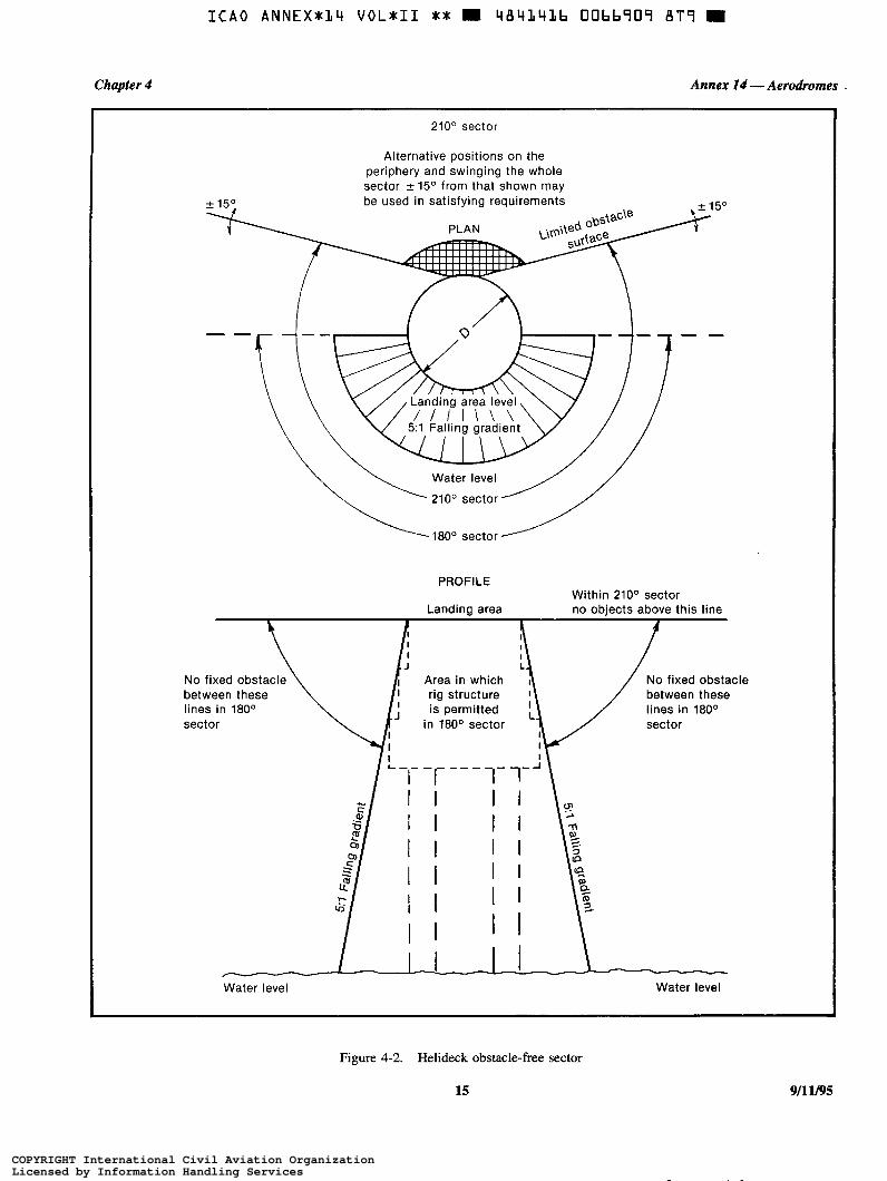
Chapter 4 Annex I4 - Aerodromes
210° sector
Alternative positions on the periphery and swinging the whole sector f 1 5 O from that shown may
PROFILE Within 210° sector
Landing area no objects above this line
No fixed obstacle No fixed obstacle between these between these lines in 180° lines in 180° sector in 180° sector
1 I I 1
Water level Water level
Figure 4-2. Helideck obstacle-free sector
15 9/11/95
COPYRIGHT International Civil Aviation OrganizationLicensed by Information Handling ServicesCOPYRIGHT International Civil Aviation OrganizationLicensed by Information Handling Services
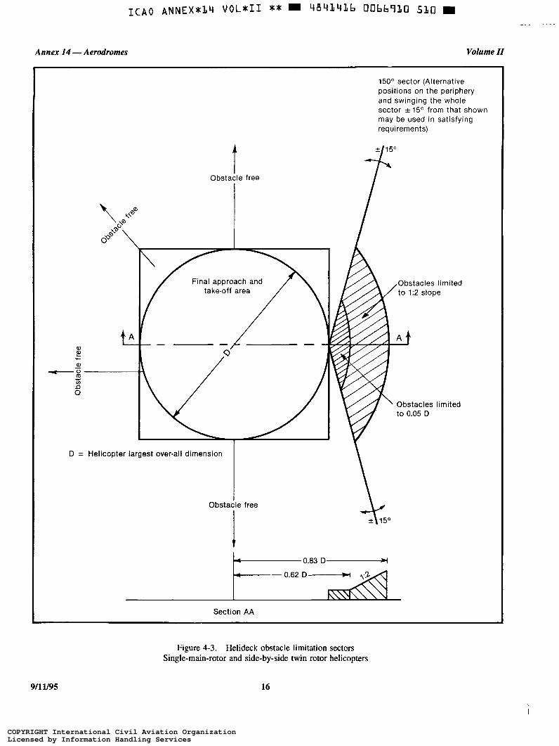
Annex 14 -Aerodromes Volume II
t Obstacle free
D = Helicopter largest over-all dimension
I Obstacle free
15O0 sector (Alternative positions on the periphery and swinging the whole sector f 1 5 O from that shown may be used in satisfying requirements)
Obstacles limited
' Obstacles limited to 0.05 D
Section AA
Figure 4-3. Helideck obstacle limitation sectors Single-main-rotor and side-by-side twin rotor helicopters
9/1 y95 16
COPYRIGHT International Civil Aviation OrganizationLicensed by Information Handling ServicesCOPYRIGHT International Civil Aviation OrganizationLicensed by Information Handling Services

Chapter 4 Annex 14 -Aerodromes
Obstacle free
150° sector (Alternative positions on the periphery and swinging the whole sector k 1 5 O from that shown may be used in satisfying requirements)
D = Helicopter largest over-all dimension
Obsta
I f 1 5 O
limited
e free 1 1 5 O
4 0.83 D-
.I 0.62 D-
V / / A Section AA
Figure 4-4. Helideck obstacle limitation sectors Tandem-main-rotor helicopters - Omnidirectional operations
17 911 Y95
COPYRIGHT International Civil Aviation OrganizationLicensed by Information Handling ServicesCOPYRIGHT International Civil Aviation OrganizationLicensed by Information Handling Services

Annex 14 -Aerodromes Volume II
t
0.9 1 D
\
ti-
l r
Final approach and take-off area
Landing direction
Landing direction
I 150° sector (No alternative position is
Obstacles limited to 1.1 m
Obstacle free I
D = Helicopter largest over-all dimension
\
Figure 4-5. Helideck obstacle limitation sectors Tandem-main-rotor helicopters - Bi-directional operations
911 U95 18
COPYRIGHT International Civil Aviation OrganizationLicensed by Information Handling ServicesCOPYRIGHT International Civil Aviation OrganizationLicensed by Information Handling Services

I C A 0 A N N E X x L 4 VOLS11 ** m 48YL41b OObbq33 2 2 ~ 9
Chapter 4 Annex 14 - Aerodromes
Final approach and take-off area (FATO
Take-off climb/ approach surface
Shaded area to have same characteristics as safety area
A. Circular final approach and take-off area (straight approach-departure)
Take-off climb/ approach
Safety area I d. Safety area
Shaded area to have same characteristics as safety area
B. Squared final approach and take-off area (straight approach-departure)
1:,11 'P Final approachltake-off area
a, 0 U a,
m c c " z
.- LL
c -
Safety area
C. Squared final approach and take-off area (curved approach-departure)
Final width 4
Figure 4-6. Take-off climb/approach surface (non-instrument FATO)
19 911 li95
COPYRIGHT International Civil Aviation OrganizationLicensed by Information Handling ServicesCOPYRIGHT International Civil Aviation OrganizationLicensed by Information Handling Services

Annex 14 -Aerodromes Volume II
PLAN
90 m
1 7 30 '/o - "
Extended centre line
Figure 4-7. Take-off climb surface for instrument FATO
911 y95 20
COPYRIGHT International Civil Aviation OrganizationLicensed by Information Handling ServicesCOPYRIGHT International Civil Aviation OrganizationLicensed by Information Handling Services

Chapter 4
I C A 0 A N R I E X * L Y V O L * I I ** m 48414Lb 00bb9L5 O T 2 W
Annex 14 - Aerodromes
9( I
A o) al 'D al
al 3
L
1 800 m O c
Extended centre line
. I
PROFILE - 6O approach Horizontal
Figure 4-8. Approach surface for precision approach FATO
21 911 1/95
COPYRIGHT International Civil Aviation OrganizationLicensed by Information Handling ServicesCOPYRIGHT International Civil Aviation OrganizationLicensed by Information Handling Services

I C A 0 A N N E X * 1 4 VOL811 ** m 484141b 00bb91b T39 m
Annex 14 - Aerodromes
PLAN
90 m
1 1 \ 16% _. Extended centre line - "
PROFILE
f 890 m
Figure 4-9. Approach surface for non-precision approach FATO
Volume II
I 911 1/95 22
COPYRIGHT International Civil Aviation OrganizationLicensed by Information Handling ServicesCOPYRIGHT International Civil Aviation OrganizationLicensed by Information Handling Services
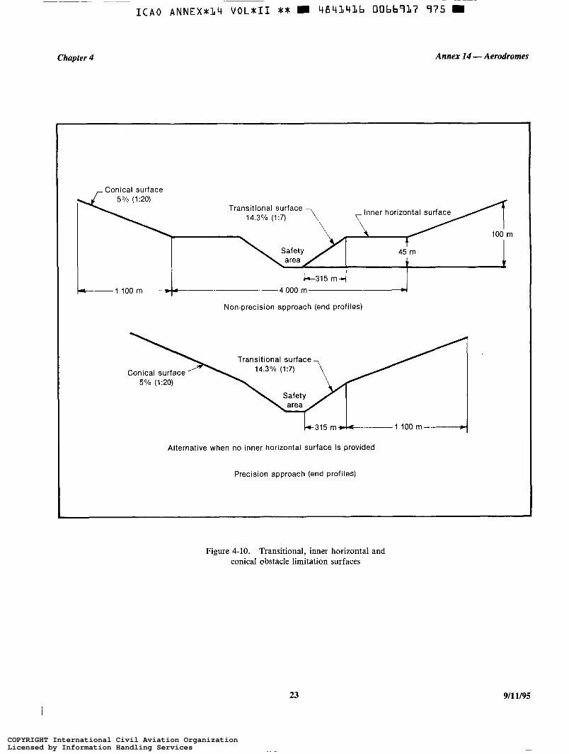
ICA0 ANNEX* l I ) V O L X I I ** 4841436 O066937 975 m
Chapter 4 Annex 14 -Aerodromes
r Conical surface
T 1 100 m”-4 O00 m-
Non-precision approach (end profiles)
Transitional surface - Inner horizontal surface
100 rn t
1 I 45 m
Transitional surface
Conical surface 5% (1%)
Alternative when no inner horizontal surface is provided
Precision approach (end profiles)
Figure 4-10. Transitional, inner horizontal and conical obstacle limitation surfaces
23 9/11/95
COPYRIGHT International Civil Aviation OrganizationLicensed by Information Handling ServicesCOPYRIGHT International Civil Aviation OrganizationLicensed by Information Handling Services
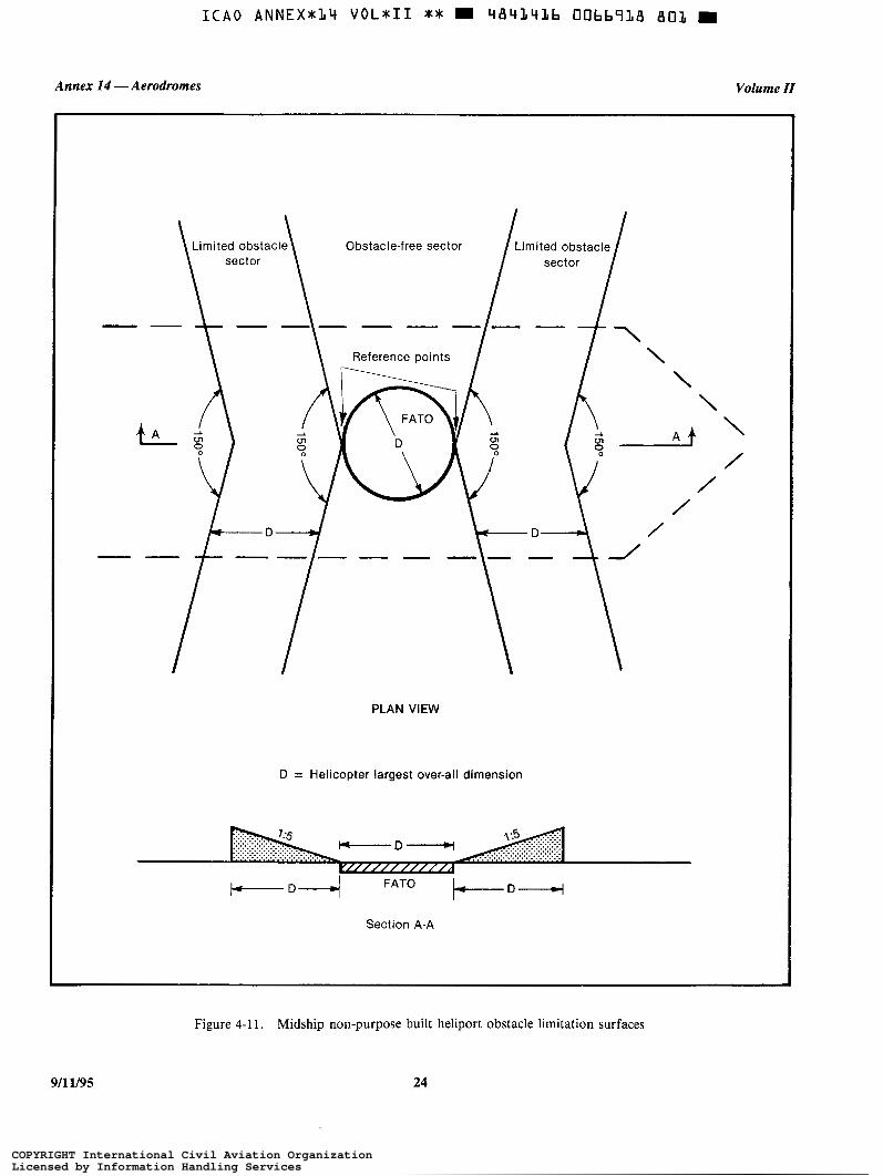
Annex I4 - Aerodromes Volume II
PLAN VIEW
D = Helicopter largest over-all dimension
Section A-A
Figure 4-1 1. Midship non-purpose built heliport obstacle limitation surfaces
9/11/95 24
COPYRIGHT International Civil Aviation OrganizationLicensed by Information Handling ServicesCOPYRIGHT International Civil Aviation OrganizationLicensed by Information Handling Services

Chapter 4 Annex 14 - Aerodromes
1.5 D
Obstacle-free sector
D = Helicopter largest over-all dimension
Figure 4-12. Ships-side non-purpose built heliport obstacle limitation surfaces
25 911 1/95
COPYRIGHT International Civil Aviation OrganizationLicensed by Information Handling ServicesCOPYRIGHT International Civil Aviation OrganizationLicensed by Information Handling Services

Annex 14 -Aerodromes Volume II
Table 4-1. Dimensions and slopes of obstacle limitation surfaces
NON-INSTRUMENT AND NON-PRECISION FATO
Non-instrument (visual) FATO Non-precision (instrument
Helicopter performance class approach) Surface and dimensions 1 2 3 FATO
APPROACH SURFACE Width of inner edge Location of inner edge
First section Divergence
Length
Outer width
Slope (maximum)
Second section Divergence
Length
Outer width
Slope (maximum)
Third section Divergence Length
Outer width
Slope (maximum)
INNER HORIZONTAL Height Radius
CONICAL Slope Height
TRANSITIONAL Slope Height
- day - night - day - night - day - night
- day - night - day - night - day - night
- day - night - day - night
10% 15%
245 ma 245 ma 49 mb
73.5 mb %%a
10% 15%
C
C
d d
12.5%
parallel e
e
d d
15%
- -
- -
- -
Width of safety area Boundary
10% 15%
245 ma 245 ma 49 mb
73.5 mb 8 %a
10% 15%
C
C
d d
12.5%
parallel e
e
d d
15%
10% 15%
245 ma 245 ma 49 mb
73.5 mb
10% 15%
C
C
d d
12.5%
parallel e
e
d d
15%
Width of safety area Boundary
16%
2 5 0 0 m
890 m
3.33%
45 m 2000m
5% 55 m
20% 45 m
a. Slope and length enables helicopters to decelerate for landing while observing "avoid" areas. b. The width of the inner edge shall be added to this dimension. c. Determined by the distance from the inner edge to the point where the divergence produces a width of 7 rotor diameters for day operations or
d. Seven rotor diameters over-all width for day operations or I O rotor diameters over-all width for night operations. e. Determined by the distance from inner edge to where the approach surface reaches a height of 150 m above the elevation of the inner edge.
1 O rotor diameters for night operations.
911 Y95 26
COPYRIGHT International Civil Aviation OrganizationLicensed by Information Handling ServicesCOPYRIGHT International Civil Aviation OrganizationLicensed by Information Handling Services

ICA0 A N N E X 8 1 4 VOL*II ** W 484l14Lb 00bb92L 3Tb H
Chapter 4 Annex 14 -Aerodromes
Table 4-2. Dimensions and slopes of obstacle limitation surfaces
INSTRUMENT (PRECISION APPROACH) FATO
6' approach
Height above FATO
3" approach
Height above FATO
9 0 m 60 m 45 m 30 m 90m 60 m 45 m 30 m (300ft) (200ft) (150ft) (l00ft) (300ft) (2ooft) (150 ft) (looft) Surface and dimensions
APPROACH SURFACE
Length of inner edge
Distance from end of FATO
90m 90m 90m 90m 90m 90m 90m 90m
60m 60m 60m 60m 60 m 60m 60m 60m
Divergence each side to height above FATO
25 % 25% 25% 25% 25% 25% 25% 25%
Distance to height above FATO 1745m 1 163m 872m 581 m 870m 580 m 435 m 290m
Width at height above FATO 962 m 671 m 526 m 380 m 521 m 380111 307.5 m 235m
Divergence to parallel section 15% 15% 15% 15% 15% 15% 15% 15%
Distance to parallel section
Width of parallel section
2793 m 3 763 m 4246m 4733 m 4250m 4733111 4975m 5217111
1800m 1800m 1800m 1800m 1800m 1800m 1800m 1800m
Distance to outer edge 5 462 m 5 074 m 4 882m 4686 m 3380111 3187111 3090m 2993111
Width at outer edge 1800m 1800m 1800m 1800m 1800m 1800m 1800111 1800m
Slope of first section 2.5% 2.5% 2.5% 2.5% (1:40) (1:40) (1:40) (1:40)
5% 5% 5% 5% (1:20) (1:20) (1:20) (1:20)
Length of first section 1500m 1500m 1500m 1500m
Slope of second section 3% 3% 3% 3% (1:33.3) (1:33.3) (1 :33.3) (1 :33.3)
6% 6% 6% 6% (1:16.66) (1:16.66) (1:16.66) (1:16.66)
Length of second section 2500m 2500m 2500m 2500m 1 250 m 1 250 m 1 250 m 1250m
Total length of surface l 0 0 0 0 m 10000m l0000m 10000m 8500m 8500m 8500m 8500m
CONICAL Slope Height
5% 5% 5% 5% 55 m 55 m 55 m 55 m
5% 5% 5% 5% 5 5 m 5 5 m 55m 55m
TRANSITIONAL Slope Height
14.3% 14.3% 14.3% 14.3% 45 m 45 m 45 m 45 m
14.3% 14.3% 14.3% 14.3% 45 m 45 m 45 m 45 m
27 911 1/95
COPYRIGHT International Civil Aviation OrganizationLicensed by Information Handling ServicesCOPYRIGHT International Civil Aviation OrganizationLicensed by Information Handling Services

I C A 0 A N N E X * ( / 4 VOL*II ** m 4 8 4 1 4 1 6 0066922 232 m
Annex I4 - Aerodromes Volume II
Table 4-3. Dimensions and slopes of obstacle limitation surfaces
STRAIGHT TAKE-OFF
Non-instmment (visual)
Helicopter performance class 1 2 3 Surface and dimensions Instrument
TAKE-OFF CLIMB
Width of inner edge Location of inner edge
First section
Divergence
Length
Outer width
Slope (maximum)
Second section
Divergence
Length
Outer width
Slope (maximum)
Third section
Divergence
Length
Outer width
Slope (maximum)
Width of safety area Boundary or end of clearway
90 m Boundary or
end of clearway
- day - night
- day - night
- day - night
10% 10% 15% 15%
10% 15%
30%
2 850 m
1800m
3.5%
a 245 mb a 245 mb
245 mb 245 mb
4.5%* 8%b 8%b
- day - night
parallel parallel
10% 15%
10% 15%
parallel
1 510 m
1 8 0 0 m
3.5%*
- day - night
a
a
e e
a a
- day - night
C
C
C
C
C
C
4.5%* 15% 15%
parallel parallel parallel
7 640 m - day - night
e e
e
e
1 8 0 0 m - day - night
C
C
C
C
15% 15% 2%
a. Determined by the distance from the inner edge to the point where the divergence produces a width of 7 rotor diameters for day operations or
b. Slope and length provides helicopters with an area to accelerate and climb while observing "avoid" areas. c. Seven rotor diameters over-all width for day operations or 10 rotor diameters over-all width for night operations. d. The width of the inner edge shall be added to this dimension. e. Determined by the distance from the inner edge to where the surface reaches a height of 150 m above the elevation of the inner edge.
10 rotor diameters for night operations.
* This slope exceeds the maximum mass one-engine-inoperative climb gradient of many helicopters which are currently operating.
911 1/95 28
COPYRIGHT International Civil Aviation OrganizationLicensed by Information Handling ServicesCOPYRIGHT International Civil Aviation OrganizationLicensed by Information Handling Services

I C A 0 ANNEX*14 VOL811 ** W 484141b 00bb723 177 m ~~
Chapter 4
Facility Requirement
Annex 14 - Aerodromes
Table 4-4. Criteria for curved take-off climb/approach area
NON-INSTRUMENT FINAL APPROACH AND TAKE-OFF
Directional change
Radius of turn on centre line
Distance to inner gate*
Width of inner gate - day
- night
Width of outer gate - day
- night
Elevation of inner and outer gates
Slopes
Divergence
Total length of area
As required ( 1 20" max).
Not less than 270 m.
(a) For performance class 1 helicopters - not less than 305 m from the end of the safety area or helicopter clearway.
(b) For performance class 2 and 3 helicopters - not less than 370 m from the end of the FATO.
Width of the inner edge plus 20% of distance to inner gate.
Width of the inner edge plus 30% of distance to inner gate.
Width of inner edge plus 20% of distance to inner gate out to minimum width of 7 rotor diameters.
Width of inner edge plus 30% of distance to inner gate out to a minimum width of 10 rotor diameters.
Determined by the distance from the inner edge and the designated gradient(s).
As given in Tables 4- 1 and 4-3.
As given in Tables 4-1 and 4-3.
As given in Tables 4-1 and 4-3.
* This is the minimum distance required prior to initiating a turn after take-off or completing a turn in the final phase.
Note.- More than one turn may be necessary in the total length of the take-off climb/approach area. The same criteria will apply for each subsequent turn except that the widths of the inner and outer gates will normally be the maximum width of the area.
29 911 1/95
COPYRIGHT International Civil Aviation OrganizationLicensed by Information Handling ServicesCOPYRIGHT International Civil Aviation OrganizationLicensed by Information Handling Services
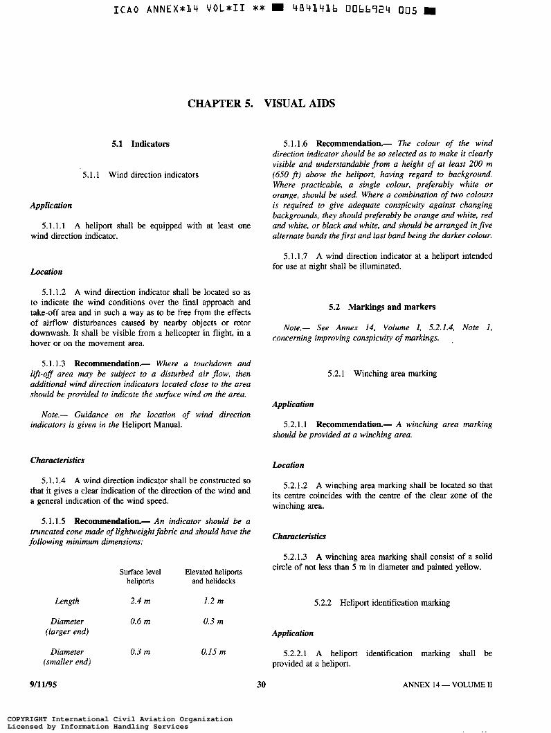
CHAPTER 5.
5.1 Indicators
5. l. 1 Wind direction indicators
Application
5.1 . l . 1 A heliport shall be equipped with at least one wind direction indicator.
Location
5.1.1.2 A wind direction indicator shall be located so as to indicate the wind conditions over the final approach and take-off area and in such a way as to be free from the effects of aifflow disturbances caused by nearby objects or rotor downwash. It shall be visible from a helicopter in flight, in a hover or on the movement area.
5.1.1.3 Recommendation.- Where a touchdown and lift-off area may be subject to a disturbed air flow, then additional wind direction indicators located close tu the area should be provided to indicate the su$ace wind on the area.
Note.- Guidance on the location of wind direction indicators is given in the Heliport Manual.
Characteristics
5.1.1.4 A wind direction indicator shall be constructed so that it gives a clear indication of the direction of the wind and a general indication of the wind speed.
5.1.1.5 Recommendation.- An indicator should be a truncated cone made of lightweight fabric and should have the following minimum dimensions:
Surface level Elevated heliports heliports and helidecks
Length 2.4 m 1.2 m
Diameter 0.6 m 0.3 m (larger end)
Diameter 0.3 m 0.15 m (smaller end)
VISUAL AIDS
5.1.1.6 Recommendation.- The colour of the wind direction indicator should be so selected as to make it clearly visible and understandable from a height of at least 200 m (650 j ì ) above the heliport, having regard to background. Where practicable, a single colour, preferably white or orange, should be used. Where a combination of two colours is required to give adequate conspicuity against changing backgrounds, they should preferably be orange and white, red and white, or black and white, and should be arranged in five alternate bands thefirst and last band being the darker colour.
5.1.1.7 A wind direction indicator at a heliport intended for use at night shall be illuminated.
5.2 Markings and markers
Note.- See Annex 14, Volume I , 5.2.1.4, Note I , concerning improving conspicuity of markings. .
5.2.1 Winching area marking
Application
5.2.1.1 Recommendation.- A winching area marking should be provided at a winching area.
Location
5.2.1.2 A winching area marking shall be located so that its centre coincides with the centre of the clear zone of the winching area.
Characteristics
5.2.1.3 A winching area marking shall consist of a solid circle of not less than 5 m in diameter and painted yellow.
5.2.2 Heliport identification marking
Application
5.2.2.1 A heliport identification marking shall be provided at a heliport.
911 1/95 30 ANNEX 14 - VOLUME II
COPYRIGHT International Civil Aviation OrganizationLicensed by Information Handling ServicesCOPYRIGHT International Civil Aviation OrganizationLicensed by Information Handling Services
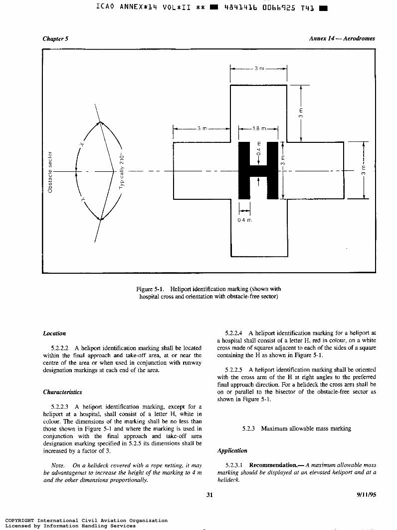
I C A 0 ANNEX*:/4 voL*II * S m 4 8 4 3 4 3 6 00bb925 T 4 1 m ~~
Chapter 5 Annex 14 -Aerodromes
\
1 - 3 7
t-3m"l l-"~8ml 1 I
Figure 5- l . Heliport identification marking (shown with hospital cross and orientation with obstacle-free sector)
Location
5.2.2.2 A heliport identification marking shall be located within the final approach and take-off area, at or near the centre of the area or when used in conjunction with runway designation markings at each end of the area.
Characteristics
5.2.2.3 A heliport identification marking, except for a heliport at a hospital, shall consist of a letter H, white in colour. The dimensions of the marking shall be no less than those shown in Figure 5-1 and where the marking is used in conjunction with the final approach and take-off area designation marking specified in 5.2.5 its dimensions shall be increased by a factor of 3.
Note.- On a helideck covered with a rope netting, it m a y be advantageous to increase the height of the marking to 4 m and the other dimensions proportionally.
5.2.2.4 A heliport identification marking for a heliport at a hospital shall consist of a letter H, red in colour, on a white cross made of squares adjacent to each of the sides of a square containing the H as shown in Figure 5- 1.
5.2.2.5 A heliport identification marking shall be oriented with the cross arm of the H at right angles to the preferred final approach direction. For a helideck the cross arm shall be on or parallel to the bisector of the obstacle-free sector as shown in Figure 5-1.
5.2.3 Maximum allowable mass marking
Application
5.2.3.1 Recommendation.- A maximum allowable mass marking should be displayed at an elevated heliport and at a helideck.
31 911 1/95
COPYRIGHT International Civil Aviation OrganizationLicensed by Information Handling ServicesCOPYRIGHT International Civil Aviation OrganizationLicensed by Information Handling Services

I C A 0 A N N E X * l 4 V O L * I I ** 4 8 4 1 4 1 6 0066926 988 m
Annex 14 -Aerodromes Volume II
Location 5.2.4.5 A final approach and take-off area marking shall be white.
5.2.3.2 Recommendation.- A maximum allowable m a s s marking should be located within the touchdown and lift-off area and so arranged as to be readable from the preferred final approach direction. 5.2.5 Final approach and take-off area
designation marking
Characteristics Application
5.2.3.3 A maximum allowable mass marking shall consist of a two digit number followed by a letter “t” to indicate the 5.2.5.1 Recommendation.- A final approach and take- allowable helicopter mass in tonnes ( 1 O 0 0 kg). off area designation marking should be provided where it is
necessary to designate the final approach and take-off area to 5.2.3.4 Recommendation.- The numbers and the letter the pilot.
of the marking should have a colour contrasting with the background and should be in the form and proportion shown in Figure 5-2. Location
5.2.4 Final approach and take-off area marking or marker
5.2.5.2 A final approach and take-off area designation marking shall be located at the beginning of the final approach and take-off area as shown in Figure 5-3.
Application Characteristics
5.2.4.1 Final approach and take-off area marking or markers shall be provided at a surface level heliport on ground 5.2.5.3 A final approach and take-off area designation where the extent of the final approach and take-off area is not marking shall consist of a runway designation marking self-evident. described in Annex 14, Volume I, 5.2.2.4 and 5.2.2.5
supplemented by an H, specified in 5.2.2 above, and as shown in Figure 5-3.
Location
5.2.4.2 Final approach and take-off area marking or markers shall be located on the boundary of the final approach and take-off area.
5.2.6 Aiming point marking
Application Characteristics
5.2.6.1 Recommendation.- An aiming point marking 5.2.4.3 Final approach and take-off area marking or should be provided at a heliport where it is necessary for a
markers shall be spaced pilot to make an approach to a particular point before proceeding to the touchdown and 113-off area.
a) for a square or rectangular area at equal intervals of not more than 50 m with at least three markings or markers on each side including a marking or marker at each corner; and
- Location
b) for any other shaped area, including a circular area, at the final approach and take-off area. 5.2.6.2 The aiming point marking shall be located within
equal intervals of not more than 10 m with a minimum number of five markings or markers.
5.2.4.4 A final approach and take-off area marking shall Characteristics be a rectangular stripe with a length of 9 m or one-fifth of the side of the final approach and take-off area which it defines 5.2.6.3 The aiming point marking shall be an equilateral and a width of 1 m. Where a marker is used its characteristics triangle with the bisector of one of the angles aligned with the shall conform to those specified in Annex 14, Volume I, preferred approach direction. The marking shall consist of 5.5.8.3 except that the height of the marker shall not exceed continuous white lines and the dimensions of the marking shall 25 cm above ground or snow level. conform to those shown in Figure 5-4.
911 v95 32
COPYRIGHT International Civil Aviation OrganizationLicensed by Information Handling ServicesCOPYRIGHT International Civil Aviation OrganizationLicensed by Information Handling Services
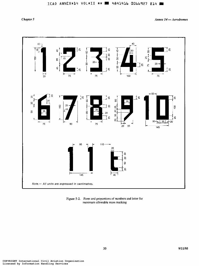
Chapter 5
ICA0 ANNEX*:/4 VOLXII X * 4841436 0066927 B 1 4 m
Annex 14 - Aerodromes
10- I!
40
In m i' Q, O
L
L 20
O Cu 7-
O
7 L 7- u) m
m t i
I- 75 4
I
H 75 u
20 55
L
L 20+ 1 3 5 w 2 0
145 - \
1 1 i O m O Cu
O In
O N
Note.- All units are expressed in centimetres.
Figure 5-2. Form and proportions of numbers and letter for maximum allowable mass marking
33 911 1/95
COPYRIGHT International Civil Aviation OrganizationLicensed by Information Handling ServicesCOPYRIGHT International Civil Aviation OrganizationLicensed by Information Handling Services
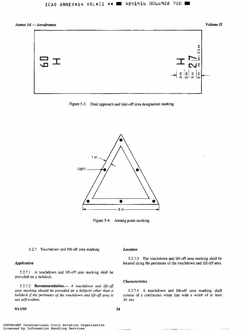
t
c\
c:
Figure 5-3. Final approach and take-off area designation marking
L 9 m - I
Figure 5-4. Aiming point marking
5.2.7 Touchdown and lift-off area marking
Application
Location
Volume N
-
5.2.7.3 The touchdown and lift-off area marking shall be located along the perimeter of the touchdown and lift-off area.
5.2.7.1 A touchdown and lift-off area marking shall be provided on a helideck.
Characteristics 5.2.1.2 Recommendation.- A touchdown and lifr-off
urea marking should be provided on a heliport other than a 5.2.7.4 A touchdown and lift-off area marking shall helideck if ?he perimeter of the touchdown and lift-off area is consist of a continuous white line with a width of at least not self-evident. 30 cm.
911 Y95 34
COPYRIGHT International Civil Aviation OrganizationLicensed by Information Handling ServicesCOPYRIGHT International Civil Aviation OrganizationLicensed by Information Handling Services
Chapter 5 Annex 14 -Aerodromes
5.2.8 Touchdown marking Characteristics
5.2.9.3 A heliport name marking shall consist of the name Application or the alphanumeric designator of the heliport as used in the
IUT communications. 5.2.8.1 Recommendation.- A touchdown marking
should be provided where it is necessary for a helicopter to touch down in a specijïc position.
5.2.9.4 Recommendatioa- The characters of the marking should be not less than 3 m in height at surface level heliports and not less than 1.2 m on elevated heliports and
Location helidecks. The colour of the marking should contrast with the background.
5.2.8.2 A touchdown marking shall be located so that when a helicopter for which the marking is intended 5.2.9.5 A heliport name marking intended for use at night is positioned, with the main undercarriage inside the or during conditions of poor visibility shall be illuminated, marking and the pilot situated over the marking, all parts either internally or externally. of the helicopter will be clear of any obstacle by a safe margin.
5.2.8.3 On a helideck or on an elevated heliport the centre of the touchdown marking shall be located at the centre of the
5.2.10 Helideck obstacle-free sector marking
touchdown and lift-off area except that the marking may be offset away from the origin of the obstacle-free sector by no Application more than 0.1 D where an aeronautical study indicates such offsetting to be necessary and that a marking so offset would not adversely affect the safety.
5.2.10.1 Recommendation.- A helideck obstacle-free sector marking should be provided at a helideck.
Characteristics Location
5.2.8.4 A touchdown marking shall be a yellow circle and have a line width of at least 0.5 m. For a helideck the line located on the touchdown area width shall be at least 1 m.
5.2.10.2 A helideck obstacle-free sector marking shall be
5.2.8.5 On helidecks the inner diameter of the circle shall Characteristics be half the D value of the helideck or 6 m whichever is the greater. 5.2.10.3 The helideck obstacle-free sector marking shall
indicate the origin of the obstacle free sector, the directions of the limits of the sector and the D value of the helideck as shown in Figure 5-5 for a hexagonal-shaped helideck.
5.2.9 Heliport name marking Note.- D is the largest dimension of the helicopter when the rotors are turning.
Applicution 5.2.10.4 The height of the chevron shall equal the width
5.2.9.1 Recommendation.- A heliport name marking should be provided at a heliport where there is insuficient alternative means of visual identification. 5.2.10.5 The chevron shall be black.
of the touchdown and lift-off area marking.
Location 5.2.1 1 Marking for taxiways
5.2.9.2 Recommendation.- The heliporr name marking should be placed on the heliport so as to be visible, as far as Note.- The specifications for taxiway centre line marking practicable, at ail angies above the hori;ontai. Where an and taxi-holding position markings in Annex 14, Volume I, obstacle sector exists the marking should be located on the 5.2.8 and 5.2.9 are equally applicable to taxiways intended for obstacle side of the H identification marking. ground taxiing of helicopters.
com. 20/1W95
35 9/11/95
COPYRIGHT International Civil Aviation OrganizationLicensed by Information Handling ServicesCOPYRIGHT International Civil Aviation OrganizationLicensed by Information Handling Services

Annex 14 -Aerodromes
5.2.12 Air taxiway markers
Application
5.2.12.1 Recommendation.- An air taxiway should be marked with air taxiway markers.
Volume II
be a rectangle with a height to width ratio of approximately 3 to 1 and shall have a minimum area of 150 cm' as shown in Figure 5-6.
5.2.12.4 An air taxiway marker shall be divided into three equal, horizontal bands coloured yellow, green and yellow, respectively. If the air taxiway is to be used at night, the markers shall be internally illuminated or retro-reflective.
Note.-- These markers are not meant to be used on helicopter ground taxiways.
5.2.13 Air transit route markers
Location Application
5.2.12.2 Air taxiway markers shall be located along the centre line of the air taxiway and shall be spaced at intervals of not more than 30 m on straight sections and 15 m on curves.
5.2.13.1 Recommendation.- When established an air transit route should be marked with air transit route markers.
Location Characteristics
5.2.12.3 An air taxiway marker shall be frangible and when installed shall not exceed 35 cm above ground or snow level. The surface of the marker as viewed by the pilot shall
5.2.13.2 Air transit route markers shall be located along the centre line of the air transit route and shall be spaced at intervals of not more than 60 m on straight sections and 15 m on curves.
r""""
I I I I
' " I
I I I I I
Obstacle sector
Black White
l m l m
Touchdown and lift-off area marking
c D value
911 1/95
Figure 5-5. Helideck obstacle-free sector marking
36
COPYRIGHT International Civil Aviation OrganizationLicensed by Information Handling ServicesCOPYRIGHT International Civil Aviation OrganizationLicensed by Information Handling Services
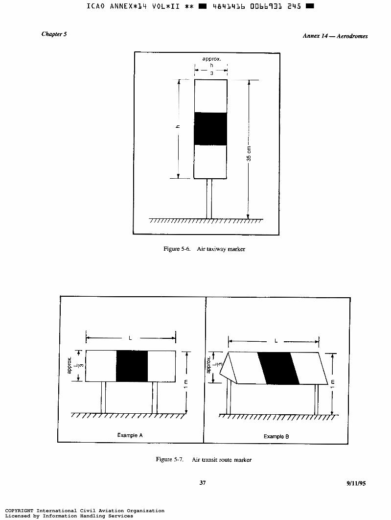
ICA0 ANNEXbLLt VOLbII b t m LtBLtLYLb 0066733 2Y5 m
Chapter 5
Hi approx.
-I
I m o
r I
Figure 5-6. Air taxiway marker
Example A
Annex 14 - Aerodromes
Example B
Figure 5-7. Air transit route marker
37 9/11/95
COPYRIGHT International Civil Aviation OrganizationLicensed by Information Handling ServicesCOPYRIGHT International Civil Aviation OrganizationLicensed by Information Handling Services

ICA0 ANNEX+L4 VOLrII X + m 4843436 00bb932 181 m
Annex 14 -Aerodromes
Characteristics
5.2.13.3 An air transit route marker shall be frangible and when installed shall not exceed 1 m above ground or snow level. The surface of the marker as viewed by the pilot shall be a rectangle with a height to width ratio of approximately 1 to 3 and shall have a minimum area of I 500 cm2 as shown in the examples in Figure 5-7.
5.2.13.4 An air transit route marker shall be divided into three equal, vertical bands coloured yellow, green and yellow, respectively. If the air transit route is to be used by night, the marker shall be internally illuminated or retro-reflective.
5.3 Lights
5.3.1 General
Note I.- See Annex 14, Volume I, 5.3.1 concerning specljìcations on screening of non-aeronautical ground lights. and design of elevated and inset lights.
Note 2.- In the case of helidecks and heliports located near navigable waters, consideration needs to be given to ensuring that aeronautical ground lights do not cause confusion to mariners.
Note 3.- As helicopters will generally come very close to extraneous light sources, it is particularly important to ensure that, unless such lights are navigation lights exhibited in accordance with international regulations, they are screened or located so as to avoid direct and reflected glare,
Volume II
Note 4.- The following specifications have been developed for systems intended for use in conjunction with a non- instrument or non-precision final approach and take-off area.
5.3.2 Heliport beacon
Application
5.3.2.1 Recommendation.- A heliport beacon should be provided at a heliport where:
a) long-range visual guidance is considered necessary and is not provided by other visual means; or
b) identification of the heliport is dlfJicult due to surrounding lights.
Location
5.3.2.2 The heliport beacon shall be located on or adjacent to the heliport preferably at an elevated position and so that it does not dazzle a pilot at short range.
Note.- Where a heliport beacon is likely to daule pilots at short range it may be switched off during the final stages of the approach and landing.
Characteristics
5.3.2.3 The heliport beacon shall emit repeated series of equispaced short duration white flashes in the format in Figure 5-8.
I t Intensity
I I 2% 1 . 2 s - 0.8 S
Flash duration
milliseconds 0.5 - 2.0 I
9/11/95
Figure 5-8. Heliport beacon flash characteristics
38
COPYRIGHT International Civil Aviation OrganizationLicensed by Information Handling ServicesCOPYRIGHT International Civil Aviation OrganizationLicensed by Information Handling Services
Chapter 5
5.3.2.4 The light from the beacon shall show at all angles of azimuth.
5.3.2.5 Recommendation.- The effective light intensity distribution of each flash should be as shown in Figure 5-9, Illustration 1.
Note.- Where brilliancy control is desired, settings of IO per cent and 3 per cent have been found to be satisfactory. In addition, shielding may be necessary to ensure that pilots are not dazzled during the final stages of the approach and landing.
5.3.3 Approach lighting system
Application
5.3.3.1 Recommendation.- An approach lighting system should be provided at a heliport where it is desirable and practicable to indicate a preferred approach direction.
Location
Annex 14 - Aerodromes
5.3.3.6 Recommendation.- The light distribution of steady lights should be as indicated in Figure 5-9, Illus- tration 2 except that the intensity should be increased by a factor of 3 for a non-precision final approach and take-off area.
5.3.3.7 Sequenced flashing lights shall be omnidirectional white lights.
5.3.3.8 Recommendation.- The flashing lights should have a jlash frequency of one per second and their light distribution should be as shown in Figure 5-9, Illustration 3. The jlash sequence should commence from the outermost light and progress towards the crossbar.
5.3.3.9 Recommendation.- A suitable brilliancy control should be incorporated to allow for adjustment of light intensity to meet the prevailing conditions.
Note.- The following intensity settings have been found suitable:
a ) steady Eights - IOOper cent, 30per cent and lOper cent; and
b) flashing lights - 1 O0 per cent, I O per cent and 3 per cent.
5.3.3.2 The approach lighting system shall be located in a straight line along the preferred direction of approach.
5.3.4 Visual alignment guidance system
Characteristics Application
5.3.3.3 Recommendation.- An approach lighting system should consist of a row of three lights spaced uniformly at 30 m intervals and of a crossbar 18 m in length at a distance of 90 m from the perimeter of the final approach and rake-off area as shown in Figure 5-10. The lights forming the crossbar should be as nearly as practicable in a horizontal straight line at right angles to, and bisected by, the line of the centre line lights and spaced at 4.5 m intervals. Where there is the need to make the f i n a l approach course more conspicuous additional lights spaced uniformly at 30 m intervals should be added beyond the crossbar. The lights beyond the crossbar may be steady or sequenced flashing, depending upon the environment.
Note.- Sequenced flashing lights may be useful where identification of the approach lighting system is dificult due to surrounding lights.
5.3.3.4 Recommendation.- Where an approach lighting system is provided for a non-precision final approach and take-off area, the system should not be less than 210 m in length.
5.3.3.5 The steady lights shall be omnidirectional white lights.
5.3.4.1 Recommendation.- A visual alignment guidance system should be provided to serve the approach to a heliport where one or more of the following conditions exist especially at night:
a} obstacle clearance, noise abatement or trafic control procedures require a particular direction to beflown;
b) the environment of the heliport provides few visual s u ~ a c e cues; and
c) it is physically impracticable to install an approach lighting system.
Location
5.3.4.2 The visual alignment guidance system shall be located such that a helicopter is guided along the prescribed track towards the final approach and take-off area.
5.3.4.3 Recommendation.- The system should be located at the downwind edge of thefiml approach and take- off area and aligned along the preferred approach direction.
39 911 1/95
COPYRIGHT International Civil Aviation OrganizationLicensed by Information Handling ServicesCOPYRIGHT International Civil Aviation OrganizationLicensed by Information Handling Services
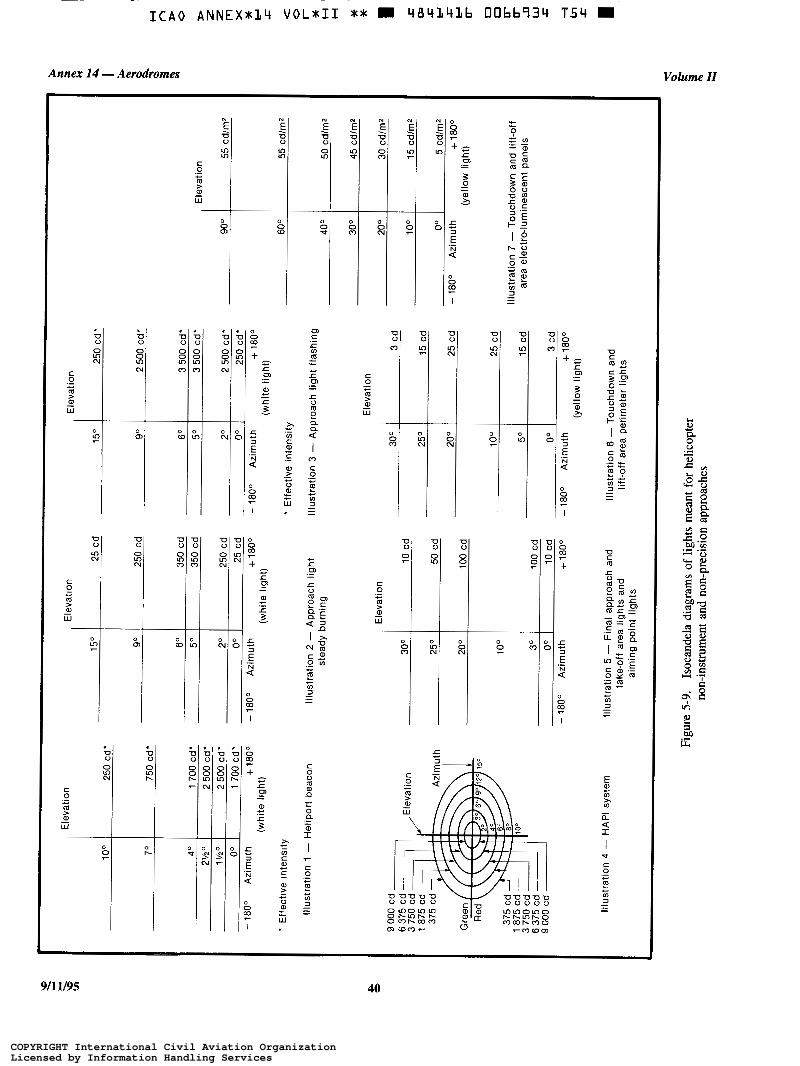
Annex 14 - Aerodromes Volume II
O C
D D
O o u 7 D U
m O N m
o c o 0 o O
O 0 o u m m m o O 0 o c
Cu m m N
I . * *
C O .- c
F - W
o
r m
o O 0 O 0 m N C Com
N
E 7 c C
D 0 O v) N
U
O m r.
c O
m al
W
._ .-
-
O
9 O
O O z +
I
t 7 c u c
o
5
O K
O C u $
U
m
c ._ c
al W
F -
N
E T
U
o C
D o Ln N
D D D u u o O 0 0 - m 9
c ._ .- F - W
O 0 0 o $ o m m o 5 z 2
m N N O 0
.-
O O z I
9/1 Y95 40
COPYRIGHT International Civil Aviation OrganizationLicensed by Information Handling ServicesCOPYRIGHT International Civil Aviation OrganizationLicensed by Information Handling Services

Chapter 5
5.3.4.4 The light units shall be frangible and mounted as low as possible.
5.3.4.5 Where the lights of the system need to be seen as discrete sources, light units shall be located such that at the extremes of system coverage the angle subtended between units as seen by the pilot shall not be less than 3 minutes of arc.
5.3.4.6 The angles subtended between light units of the system and other units of comparable or greater intensities shall also be not less than 3 minutes of arc.
Note.- Requirements of 5.3.4.5 and 5.3.4.6 can be met for lights on a line n o m l to the line of sight i f the light units are separated by I metre for every kilometre of viewing range.
Annex 14 -Aerodromes
Signal fonnat
5.3.4.7 The signal format of the alignment guidance system shall include a minimum of three discrete signal sectors providing “offset to the right”, “on track” and “offset to the left” signals.
5.3.4.8 The divergence of the “on track’’ sector of the system shall be as shown in Figure 5-1 1.
5.3.4.9 The signal format shall be such that there is no possibility of confusion between the system and any associated visual approach slope indicator or other visual aids.
5.3.4.10 The system shall avoid the use of the same coding as any associated visual approach slope indicator.
90 m
210 m
Figure 5-10. Approach lighting system
FATO
1 Example A 1 Example B
Figure 5-1 1. Divergence of the “on track” sector
41 911 1/95
COPYRIGHT International Civil Aviation OrganizationLicensed by Information Handling ServicesCOPYRIGHT International Civil Aviation OrganizationLicensed by Information Handling Services
ICA0 A N N E X t L 4 VOL*I I t* D 484L4Lb 00bb936 827 D
Annex 14 -Aerodromes
5.3.4.11 The signal format shall be such that the system is unique and conspicuous in all operational environments.
5.3.4.12 The system shall not significantly increase the pilot workload.
Light distribution
5.3.4.13 The useable coverage of the visual alignment guidance system shall be equal to or better than that of the visual approach slope indicator system, with which it is associated.
5.3.4.14 A suitable intensity control shall be provided so as to allow adjustment to meet the prevailing conditions and to avoid dazzling the pilot during approach and landing.
Approach track and azimuth setting
5.3.4.15 A visual alignment guidance system shall be capable of adjustment in azimuth to within f 5 minutes of arc of the desired approach path.
5.3.4.16 The angle of azimuth guidance system shall be such that during an approach the pilot of a helicopter at the boundary of the “on track” signal will clear all objects in the approach area by a safe margin.
5.3.4.17 The characteristics of the obstacle protection surface specified in 5.3.5.23, Table 5-1 and Figure 5-13 shall equally apply to the system.
Characteristics of the visual alignment guidance system
5.3.4.18 In the event of the failure of any component affecting the signal format the system shall be automatically switched off.
5.3.4.19 The light units shall be so designed that deposits of condensation, ice, dirt, etc. on optically transmitting or reflecting surfaces will interfere to the least possible extent with the light signal and will not cause spurious or false signals to be generated.
5.3.5 Visual approach slope indicator
Applicalion
5.3.5.1 Recommendation.- A visual approach slope indicator should be provided to serve the approach to a heliport, whether or not the heliport is served by other visual approach aids or by non-visual aids, where one or more of the following conditions exist especially at night:
911 1/95 42
Volume II
a ) obstacle clearance, noise abatement or trafic control procedures require a particular slope to be flown;
b) the environment of the heliport provides few visual sugace cues; and
c) the characteristics of the helicopter require a stabilized approach.
5.3.5.2 The standard visual approach slope indicator systems for helicopter operations shall consist of the following:
a) PAP1 and APAF’I systems conforming to the specifications contained in Annex 14, Volume I, 5.3.5.23 to 5.3.5.40 inclusive except that the angular size of the on-slope sector of the systems shall be increased to 45 minutes; or
b) helicopter approach path indicator (HAPI) system conforming to the specifications in 5.3.5.6 to 5.3.5.21 inclusive.
Location
5.3.5.3 A visual approach slope indicator shal! be located such that a helicopter is guided to the desired position within the final approach and take-off area and so as to avoid dazzling the pilot during final approach and landing.
5.3.5.4 Recommendation.- A visual approach slope indicator should be located adjacent to the nominal aiming point and aligned in azimuth with the preferred approach direction.
5.3.5.5 The light unit(s) shall be frangible and mounted as low as possible.
HAPI signal format
5.3.5.6 The signal format of the HAPI shall include four discrete signal sectors, providing an “above slope”, an “on slope”, a “slightly below” and a “below slope” signal.
5.3.5.7 The signal format of the HAPI shall be as shown in Figure 5-12, Illustrations A and B.
Note.- Care is required in the design of the unit to minimize spurious signals between the signal sectors and at the azimuth coverage limits.
5.3.5.8 The signal repetition rate of the flashing sector of the HAPI shall be at least 2 Hz.
5.3.5.9 Recommendation.- The on-to-off ratio of pulsing signals of the HAPI should be 1 to 1 and the modulation depth should be at least 80 per cent.
COPYRIGHT International Civil Aviation OrganizationLicensed by Information Handling ServicesCOPYRIGHT International Civil Aviation OrganizationLicensed by Information Handling Services
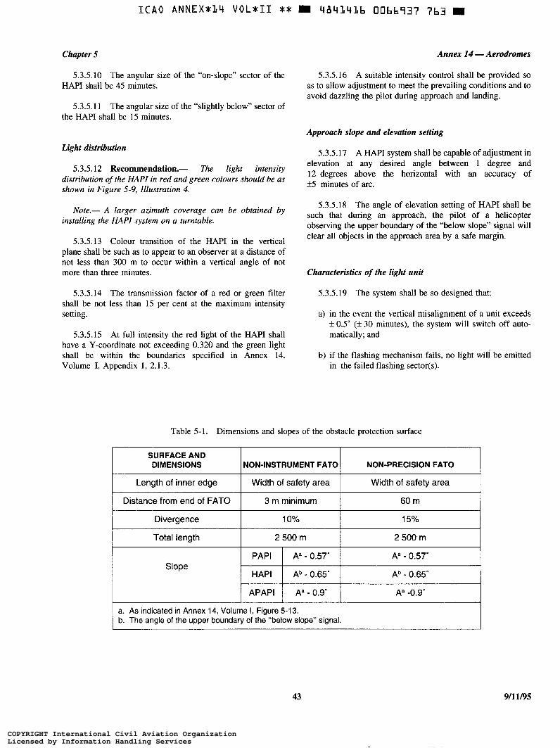
Chapter 5
5.3.5.10 The angular size of the “on-slope” sector of the HAPI shall be 45 minutes.
Annex 14 -Aerodromes
5.3.5.16 A suitable intensity control shall be provided so as to allow adjustment to meet the prevailing conditions and to avoid dazzling the pilot during approach and landing.
5.3.5.1 1 The angular size of the “slightly below” sector of the HAPI shall be 15 minutes.
Approach slope and elevation setting
Light distribution
5.3.5.12 Recommendation.- The light intensity distribution of the HAPI in red and green colours should be as shown in Figure 5-9, Illustration 4.
Note.- A larger azimuth coverage can be obtained by installing the HAPI system on a turntable.
5.3.5.13 Colour transition of the HAPI in the vertical plane shall be such as to appear to an observer at a distance of not less than 300 m to occur within a vertical angle of not more than three minutes.
5.3.5.14 The transmission factor of a red or green filter shall be not less than 15 per cent at the maximum intensity setting.
5.3.5.15 At full intensity the red light of the HAPI shall have a Y-coordinate not exceeding 0.320 and the green light shall be within the boundaries specified in Annex 14, Volume I, Appendix 1 , 2.1.3.
5.3.5.17 A HAPI system shall be capable of adjustment in elevation at any desired angle between 1 degree and 12 degrees above the horizontal with an accuracy of +5 minutes of arc.
5.3.5.18 The angle of elevation setting of HAPI shall be such that during an approach, the pilot of a helicopter observing the upper boundary of the “below slope” signal will clear all objects in the approach area by a safe margin.
Characteristics of the light unit
5.3.5.19 The system shall be so designed that:
a) in the event the vertical misalignment of a unit exceeds f 0.5” (+ 30 minutes), the system will switch off auto- matically; and
b) if the flashing mechanism fails, no light wili be emitted in the failed flashing sector(s).
Table 5-1. Dimensions and slopes of the obstacle protection surface
SURFACE AND DIMENSIONS NON-PRECISION FATO NON-INSTRUMENT FATO
Length of inner edge Width of safety area Width of safety area
Distance from end of FATO
2 500 m 2 500 m Total length
15% 10% Divergence
60 m 3 m minimum
PAPI Aa - 0.57’ Aa - 0.57’ Slope
HAPI Ab - 0.65” Ab - 0.65’
APAPI A’ -0. go A‘ - 0.9”
a. As indicated in Annex 14, Volume I, Figure 5-13. b. The angle of the upper boundary of the “below slope” signal.
43 911 1/95
COPYRIGHT International Civil Aviation OrganizationLicensed by Information Handling ServicesCOPYRIGHT International Civil Aviation OrganizationLicensed by Information Handling Services

Annex 14 - Aerodromes Volume II
Sector Format
Above Flashing green
On slope Green
Slightly Red below
Below Flashing red
Illustration A Illustration B
Figure 5- 12. HAP1 signal format
911 1/95
Figure 5-13. Obstacle protection surface for visual approach slope indicator systems
44
COPYRIGHT International Civil Aviation OrganizationLicensed by Information Handling ServicesCOPYRIGHT International Civil Aviation OrganizationLicensed by Information Handling Services
ICA0 ANNEXVJLI V O L V I 1 V * W 484L4Lb 00bb939 536 H
Chapter 5
5.3.5.20 The light unit of the HAPI shall be so designed that deposits of condensation, ice, dirt, etc. on optically transmitting or reflecting surfaces will interfere to the least possible extent with the light signal and will not cause spurious or false signals to be generated.
5.3.5.21 Recommendation.- A HAPI system intended for installation on a floating helideck should afford a stabilization of the beam to an accuracy of k 1/4" within f 3" pitch and roll movement of the heliport.
Obshcle protection surface
Note.- The following specifications apply to PAPI, APAPI and HAPI.
5.3.5.22 An obstacle protection surface shall be established when it is intended to provide a visual approach slope indicator system.
5.3.5.23 The characteristics of the obstacle protection surface, i.e. origin, divergence, length and slope shall correspond to those specified in the relevant column of Table 5-1 and in Figure 5-13.
5.3.5.24 New objects or extensions of existing objects shall not be permitted above an obstacle protection surface except when, in the opinion of the appropriate authority, the new object or extension would be shielded by an existing immovable object.
Note.- Circumstances in which the shielding principle may reasonably be applied are described in the Airport Services Manual, Part 6.
5.3.5.25 Existing objects above an obstacle protection surface shall be removed except when, in the opinion of the appropriate authority, the object is shielded by an existing immovable object, or after aeronautical study it is determined that the object would not adversely affect the safety of operations of helicopters.
5.3.5.26 Where an aeronautical study indicates that an existing object extending above an obstacle protection surface could adversely affect the safety of operations of helicopters one or more of the following measures shall be taken:
Annex 14 - Aerodromes
d) suitably displace the final approach and take-off area; and
e) install a visual alignment guidance system specified in 5.3.4.
Note.- Guidance on this issue i s contained in the Heliport Manual.
5.3.6 Final approach and take-off area lights
Application
5.3.6.1 Where a final approach and take-off area is established at a surface level heliport on ground intended for use at night, final approach and take-off area lights shall be provided except that they may be omitted where the final approach and take-off area and the touchdown and lift-off area are nearly coincidental or the extent of the final approach and take-off area is self-evident.
Location
5.3.6.2 Final approach and take-off area lights shall be placed along the edges of the final approach and take-off area. The lights shall be uniformly spaced as follows:
a) for an area in the form of a square or rectangle, at intervals of not more than 50 m with a minimum of four lights on each side including a light at each comer; and
b) for any other shaped area, including a circular area, at intervals of not more than 5 m with a minimum of ten lights.
Characteristics
5.3.6.3 Final approach and take-off area lights shall be fixed omnidirectional lights showing white. Where the intensity of the lights is to be varied the lights shall show variable white.
5.3.6.4 Recommendation.- The light distribution of final approach and rake-off area lights should be as shown in
suitably raise the approach slope of the system; Figure 5-9, Illustration 5.
reduce the azimuth spread of the system so that the object 5.3.6.5 Recommendation.- The lights should not is outside the confines of the beam; exceed a height of 25 cm and should be inset when a light
extending above the surface would endanger helicopter displace the axis of the system and its associated obstacle operations. Where a final approach and take-off area is not protection surface by no more than 5'; meant for lift-off or touchdown, the lights should not exceed a
height of 25 cm above ground or snow level.
45 9/11/95
COPYRIGHT International Civil Aviation OrganizationLicensed by Information Handling ServicesCOPYRIGHT International Civil Aviation OrganizationLicensed by Information Handling Services
Annex 14 -Aerodromes
5.3.7 Aiming point lights
Application
5.3.7.1 Recommendation.- Where an aiming point marking is provided at a heliport intended for use at night, aiming point lights should be provided.
Location
5.3.7.2 Aiming point lights shall be collocated with the aiming point marking.
Characteristics
5.3.7.3 Aiming point lights shall form a pattern of at least six omnidirectional white lights as shown in Figure 5-4. The lights shall be inset when a light extending above the surface could endanger helicopter operations.
5.3.7.4 Recommendation.- The light distribution of aiming point lights should be as shown in Figure 5-9, Illustration 5.
5.3.8 Touchdown and lift-off area lighting system
Applicalion
5.3.8.1 A touchdown and lift-off area lighting system shall be provided at a heliport intended for use at night.
5.3.8.2 The touchdown and lift-off area lighting system for a surface level heliport shall consist of one or more of the following:
a) perimeter lights; or
b) floodlighting; or
c) luminescent panel lighting when a) and b) are not practicable and final approach and take-off area lights are available.
5.3.8.3 The touchdown and lift-off area lighting system for an elevated heliport or helideck shall consist of:
a) perimeter lights; and
b) floodlighting and/or luminescent panel lighting.
Note.- At elevated heliports and helidecks, surface texture cues within the touchdown and lift-off area are essential for helicopter positioning during the final approach and landing.
Volume II
Such cues are provided by using floodlighting or luminescent panel lighting or a combination of these two forms of lighting, in addition to perimeter lights.
5.3.8.4 Recommendation.- Touchdown and 113-off area floodlighting or luminescent panel lighting should be provided at a surface-level heliport intended for use at night when enhanced sulface texture cues are required.
Location
5.3.8.5 Touchdown and lift-off area perimeter lights shall be placed along the edge of the area designated for use as the touchdown and lift-off area or within a distance of 1.5 m from the edge. Where the touchdown and lift-off area is a circle the lights shall be:
a) located on straight lines in a pattern which will provide information to pilots on drift displacement; and
b) where a) is not practicable, evenly spaced around the perimeter of the touchdown and lift-off area at the appropriate interval except that over a sector of 45" the lights shall be spaced at half spacing.
5.3.8.6 Touchdown and lift-off area perimeter lights shall be unifcrmly spaced at intervals of not more than 3 m for elevated heliports and helidecks and not more than 5 m for surface level heliports. There shall be a minimum number of four lights on each side including a light at each comer. For a circular touchdown and lift-off area, where lights are installed in accordance with 5.3.8.5 b) there shall be a minimum of fourteen lights.
Note.- Guidance on this issue is contained in the Heliport Manual.
5.3.8.7 The touchdown and lift-off area perimeter lights shall be installed at an elevated heliport or fixed helideck such that the pattern cannot be seen by the pilot from below the elevation of the touchdown and lift-off area.
5.3.8.8 The touchdown and lift-off area perimeter lights shall be installed at a floating helideck, such that the pattern cannot be seen by the pilot from below the elevation of the touchdown and lift-off area when the helideck is level.
5.3.8.9 On surface level heliports, luminescent panel lights shall be placed along the marking designating the edge of the touchdown and lift-off area. Where the touchdown and lift-off area is a circle the luminescent panels shall be located on straight lines circumscribing the area.
5.3.8.10 On surface level heliports the minimum number of panels on a touchdown and lift-off area shall be nine. The total length of luminescent panels in a pattern shall not be less than 50 per cent of the length of the pattern. There shall be an odd number with a minimum number of three panels on each
911 1/95 46
COPYRIGHT International Civil Aviation OrganizationLicensed by Information Handling ServicesCOPYRIGHT International Civil Aviation OrganizationLicensed by Information Handling Services
Chapter 5 Annex 14 - Aerodromes
side of the touchdown and lift-off area including a panel at 5.3.8.22 The spectral distribution of touchdown and lift- each corner. Luminescent panels shall be uniformly spaced off area floodlights shall be such that the surface and obstacle with a distance between adjacent panel ends of not more than marking can be correctly identified. 5 m on each side of the touchdown and lift-off area.
5.3.8.23 Recommendation.- The average horizontal
5.3.8.1 1 Recommendation.- When luminescent panels are used on an elevated heliport or helideck to enhance surface texture cues the panels should not be placed adjacent
illuminance of thefloodlighting should be at least 10 lux, with a uniformity ratio (average to minimum) of not more than 8:1 measured on the surface of the touchdown and lifr-off area.
to the perimeter lights. They should be placed around a touchdown marking where it is provided or coincident with heliport identification marking. 5.3.9 Winching area floodlighting
5.3.8.12 Touchdown and lift-off area floodlights shall be Application
located so as to avoid glare to pilots in flight or to personnel working on the area. The arrangement and aiming of floodlights shall be such that shadows are kept to a minimum.
5.3.9.1 Winching area floodlighting shall be provided at a winching area intended for use at night.
Characteristics Location
5.3.9.2 Winching area floodlights shall be located so as to
area. The arrangement and aiming of floodlights shall be such 5'3'8'13 The touchdown and area primeter lights avoid glare to pilots in flight or to personnel working on the
shall be fixed omnidirectional lights showing yellow.
5.3.8.14 At a surface level heliport the luminescent panels shall emit yellow light when used to define the boundary of the touchdown and lift-off area. Characteristics
that shadows &e kept to a minimum.
Note.- In other circumstances, luminescent panels may 5.3.9.3 The spectral distribution of winching area emit light of other colours. floodlights shall be such that the surface and obstacle
markings can be correctly identified.
5.3.8.15 Recommendation.- The chromaticity and luminance of colours of luminescent panels should conform to Annex 14, Volume I, Appendix I, 3.4.
5.3.9.4 Recommendation.- The average horizontal illuminance should be at least I O lux, measured on the surface of the winching area.
5.3.8.16 A luminescent panel shall have a minimum width of 6 cm. The panel housing shall be the same colour as 5.3.10 Taxiway lights the marking it defines.
Note.- The specifications for taxiway centre line lights 5.3.8.17 Recommendation.- The perimeter lights and taxiway edge lights in Annex 14, Volume I, 5.3.15 and
should not exceed a height of 25 cm and should be inset when 5.3.16 are equally applicable to taxiways intended for ground a light extending above the surface could endanger helicopter taxiing of helicopters. operations.
5.3.8.18 Recommendation.- The touchdown and lift- 5.3.11 Visual aids for denoting obstacles off area floodlights should not exceed a height of 25 cm.
Note.- The specifcations for marking and lighting of obstacles included in Annex 14, Volume I , Chapter 6, are 5.3.8.19 The luminescent panels shall not extend above equally applicable to heliports and winching
the surface by more than 2.5 cm.
5.3.8.20 Recommendation.- The light distribution of 5.3.12 Floodlighting of obstacles the perimeter lights should be as shown in Figure 5-9, Illustration 6. Application
5.3.8.21 Recommendation.- The light distribution of 5.3.12.1 At a heliport intended for use at night, obstacles the luminescent panels should be as shown in Figure 5-9, shall be floodlighted if it is not possible to display obstacle Illustration 7. lights on them.
47 911 1/95
COPYRIGHT International Civil Aviation OrganizationLicensed by Information Handling ServicesCOPYRIGHT International Civil Aviation OrganizationLicensed by Information Handling Services

Annex 14 -Aerodromes Volume II
Location Characteristics
5.3.12.2 Obstacle floodlights shall be arranged so as to 5.3.12.3 Recommendation.- Obstacle floodlighting illuminate the entire obstacle and as far as practicable in a should be such as to produce a luminance of at least manner so as not to dazzle the helicopter pilots. 10 caYm2.
911 1/95 48
COPYRIGHT International Civil Aviation OrganizationLicensed by Information Handling ServicesCOPYRIGHT International Civil Aviation OrganizationLicensed by Information Handling Services
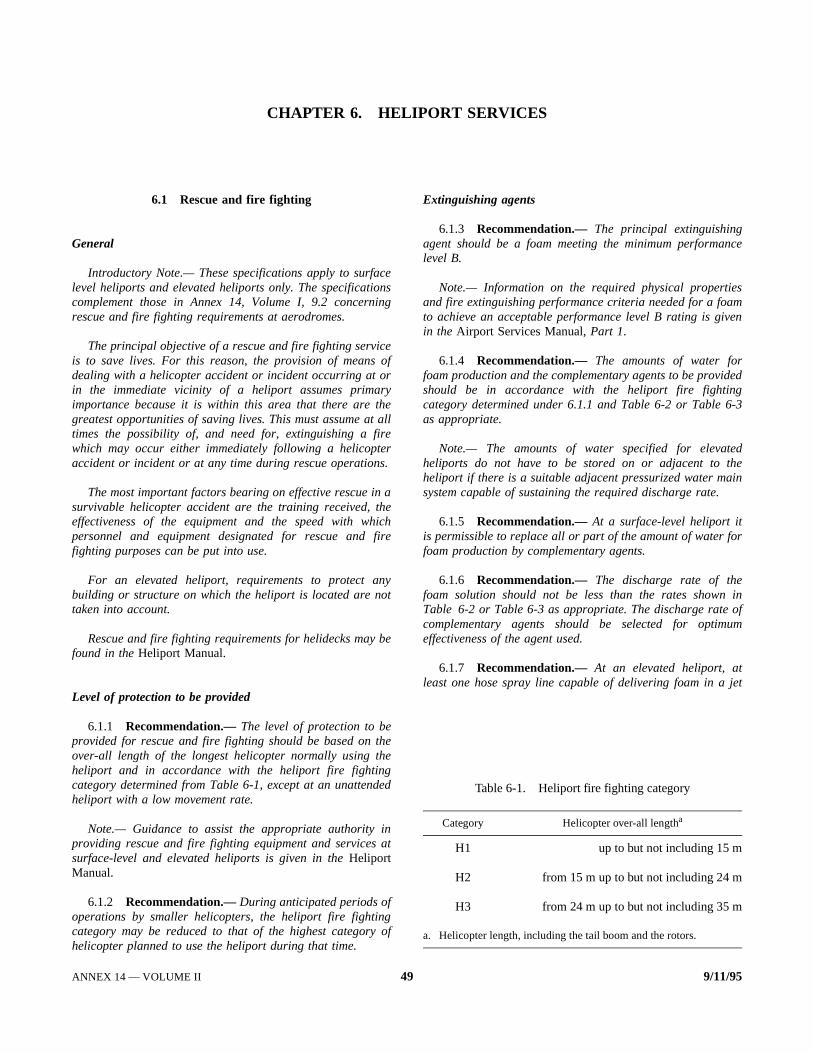
nce
smen
edg-3
edhein
or
in ofum
jet
CHAPTER 6. HELIPORT SERVICES
6.1 Rescue and fire fighting
General
Introductory Note.— These specifications apply to surfacelevel heliports and elevated heliports only. The specificationscomplement those in Annex 14, Volume I, 9.2 concerningrescue and fire fighting requirements at aerodromes.
The principal objective of a rescue and fire fighting serviceis to save lives. For this reason, the provision of means ofdealing with a helicopter accident or incident occurring at orin the immediate vicinity of a heliport assumes primaryimportance because it is within this area that there are thegreatest opportunities of saving lives. This must assume at alltimes the possibility of, and need for, extinguishing a firewhich may occur either immediately following a helicopteraccident or incident or at any time during rescue operations.
The most important factors bearing on effective rescue in asurvivable helicopter accident are the training received, theeffectiveness of the equipment and the speed with whichpersonnel and equipment designated for rescue and firefighting purposes can be put into use.
For an elevated heliport, requirements to protect anybuilding or structure on which the heliport is located are nottaken into account.
Rescue and fire fighting requirements for helidecks may befound in the Heliport Manual.
Level of protection to be provided
6.1.1 Recommendation.— The level of protection to beprovided for rescue and fire fighting should be based on theover-all length of the longest helicopter normally using theheliport and in accordance with the heliport fire fightingcategory determined from Table 6-1, except at an unattendedheliport with a low movement rate.
Note.— Guidance to assist the appropriate authority inproviding rescue and fire fighting equipment and services atsurface-level and elevated heliports is given in the HeliportManual.
6.1.2 Recommendation.— During anticipated periods ofoperations by smaller helicopters, the heliport fire fightingcategory may be reduced to that of the highest category ofhelicopter planned to use the heliport during that time.
Extinguishing agents
6.1.3 Recommendation.— The principal extinguishingagent should be a foam meeting the minimum performalevel B.
Note.— Information on the required physical propertieand fire extinguishing performance criteria needed for a foato achieve an acceptable performance level B rating is givin the Airport Services Manual, Part 1.
6.1.4 Recommendation.— The amounts of water forfoam production and the complementary agents to be providshould be in accordance with the heliport fire fightincategory determined under 6.1.1 and Table 6-2 or Table 6as appropriate.
Note.— The amounts of water specified for elevatheliports do not have to be stored on or adjacent to theliport if there is a suitable adjacent pressurized water masystem capable of sustaining the required discharge rate.
6.1.5 Recommendation.— At a surface-level heliport itis permissible to replace all or part of the amount of water ffoam production by complementary agents.
6.1.6 Recommendation.— The discharge rate of thefoam solution should not be less than the rates shownTable 6-2 or Table 6-3 as appropriate. The discharge ratecomplementary agents should be selected for optimeffectiveness of the agent used.
6.1.7 Recommendation.— At an elevated heliport, atleast one hose spray line capable of delivering foam in a
Table 6-1. Heliport fire fighting category
Category Helicopter over-all lengtha
H1 up to but not including 15 m
H2 from 15 m up to but not including 24 m
H3 from 24 m up to but not including 35 m
a. Helicopter length, including the tail boom and the rotors.
ANNEX 14 — VOLUME II 49 9/11/95ANNEX 14 — VOLUME II 49 9/11/95

Annex 14 — Aerodromes Volume II
iceutes
eenere)of
lyr
Table 6-2. Minimum usable amounts of extinguishing agentsfor surface level heliports
Table 6-3. Minimum usable amounts of extinguishing agents forelevated heliports
Foam meeting performancelevel B Complementary agents
Category
(1)
Water(L)
(2)
Discharge ratefoam solution (L/min)
(3)
Dry chemicalpowders (kg)
(4)
or
Halons(kg)
(5)
or
CO2
(kg)
(6)
H1 500 250 23 23 45
H2 1 000 500 45 45 90
H3 1 600 800 90 90 180
Foam meeting performancelevel B Complementary agents
Category
(1)
Water(L)
(2)
Discharge ratefoam solution (L/min)
(3)
Dry chemicalpowders (kg)
(4)
or
Halons(kg)
(5)
or
CO2
(kg)
(6)
H1 2 500 250 45 45 90
H2 5 000 500 45 45 90
H3 8 000 800 45 45 90
spray pattern at 250 L/min should be provided. Additionally atelevated heliports in categories 2 and 3, at least two monitorsshould be provided each having a capability of achieving therequired discharge rate and positioned at different locationsaround the heliports so as to ensure the application of foam toany part of the heliport under any weather condition and tominimize the possibility of both monitors being impaired by ahelicopter accident.
Rescue equipment
6.1.8 Recommendation.— At an elevated heliport rescueequipment should be stored adjacent to the heliport.
Note.— Guidance on the rescue equipment to be providedat a heliport is given in the Heliport Manual.
Response time
6.1.9 Recommendation.— At a surface-level heliport,the operational objective of the rescue and fire fighting servshould be to achieve response times not exceeding two minin optimum conditions of visibility and surface conditions.
Note.— Response time is considered to be the time betwthe initial call to the rescue and fire fighting service and thtime when the first responding vehicle(s) (the service) is (ain position to apply foam at a rate of at least 50 per cent the discharge rate specified in Table 6-2.
6.1.10 Recommendation.— At an elevated heliport, therescue and fire fighting service should be immediateavailable on or in the vicinity of the heliport while helicoptemovements are taking place.
9/11/95 506/11/97No. 2

APPENDIX 1. AERONAUTICAL DATA QUALITY REQUIREMENTS
Table 1. Latitude and longitude
Latitude and longitudeAccuracyData type
ClassificationIntegrity
Heliport reference point. . . . . . . . . . . . . . . . . . . . . . . . . 30 m
surveyed/calculatedroutine1 × 10-3
NAVAIDS located at the heliport. . . . . . . . . . . . . . . . . 3 m
surveyedessential1 × 10-5
Obstacles in the circling area and at the heliport. . . . . 3 m
surveyedessential1 × 10-5
Significant obstacles in the approach and take-off area . . . . . . . . . . . . . . . . . . . . . . . . . . . . . .
3 msurveyed
essential1 × 10-5
Geometric centre of TLOF or FATO thresholds . . . . . 1 m
surveyedcritical1 × 10-8
Ground taxiway centre line points, air taxiways and transit routes points . . . . . . . . . . . . . . . . . . . . . . . .
0.5 msurveyed/calculated
essential1 × 10-5
Helicopter stand-points/INS check-points. . . . . . . . . . . 0.5 m
surveyedroutine1 × 10-3
ANNEX 14 — VOLUME II 51 9/11/95ANNEX 14 — VOLUME II 51 9/11/956/11/97No. 2

Annex 14 — Aerodromes Volume II
Table 2. Elevation/Altitude/Height
Table 3. Declination and magnetic variation
Elevation/altitude/heightAccuracyData type
ClassificationIntegrity
Heliport elevation . . . . . . . . . . . . . . . . . . . . . . . . . . . . . 0.5 m or 1 ftsurveyed
essential1 × 10-5
WGS-84 geoid undulation at heliport elevation position. . . . . . . . . . . . . . . . . . . . . . . . . . . . . .
0.5 m or 1 ftsurveyed
essential1 × 10-5
FATO threshold, non-precision approaches . . . . . . . . . 0.5 m or 1 ftsurveyed
essential1 × 10-5
WGS-84 geoid undulation at FATO threshold, TLOF geometric centre, non-precision approaches . . . . . . . . .
0.5 m or 1 ftsurveyed
essential1 × 10-5
FATO threshold, precision approaches. . . . . . . . . . . . . 0.25 m or 1 ftsurveyed
critical1 × 10-8
WGS-84 geoid undulation at FATO threshold, TLOF geometric centre, precision approaches . . . . . . .
0.25 m or 1 ftsurveyed
critical1 × 10-8
Obstacles in the approach and take-off areas . . . . . . . . 1 m or 1 ftsurveyed
essential1 × 10-5
Obstacles in the circling areas and at the heliport . . . . 1 m or 1 ftsurveyed
essential1 × 10-5
Distance measuring equipment/precision (DME/P) . . . 3 m (10 ft)surveyed
essential1 × 10-5
Declination/variationAccuracyData type
ClassificationIntegrity
Heliport magnetic variation. . . . . . . . . . . . . . . . . . . . . . 1 degreesurveyed
essential1 × 10-5
ILS localizer antenna magnetic variation . . . . . . . . . . . 1 degreesurveyed
essential1 × 10-5
MLS azimuth antenna magnetic variation . . . . . . . . . . 1 degreesurveyed
essential1 × 10-5
9/11/95 526/11/97No. 2
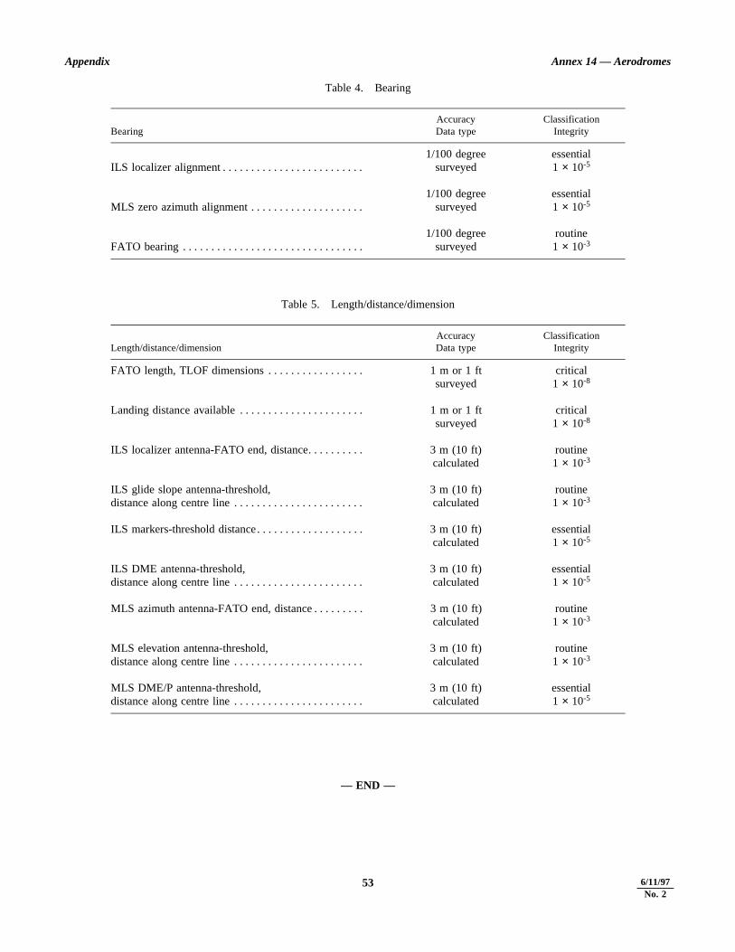
Appendix Annex 14 — Aerodromes
Table 4. Bearing
Table 5. Length/distance/dimension
— END —
BearingAccuracyData type
ClassificationIntegrity
ILS localizer alignment . . . . . . . . . . . . . . . . . . . . . . . . . 1/100 degree
surveyedessential1 × 10-5
MLS zero azimuth alignment . . . . . . . . . . . . . . . . . . . . 1/100 degree
surveyedessential1 × 10-5
FATO bearing . . . . . . . . . . . . . . . . . . . . . . . . . . . . . . . . 1/100 degree
surveyedroutine1 × 10-3
Length/distance/dimensionAccuracyData type
ClassificationIntegrity
FATO length, TLOF dimensions . . . . . . . . . . . . . . . . . 1 m or 1 ftsurveyed
critical1 × 10-8
Landing distance available . . . . . . . . . . . . . . . . . . . . . . 1 m or 1 ftsurveyed
critical1 × 10-8
ILS localizer antenna-FATO end, distance. . . . . . . . . . 3 m (10 ft)calculated
routine1 × 10-3
ILS glide slope antenna-threshold, distance along centre line . . . . . . . . . . . . . . . . . . . . . . .
3 m (10 ft)calculated
routine1 × 10-3
ILS markers-threshold distance. . . . . . . . . . . . . . . . . . . 3 m (10 ft)calculated
essential1 × 10-5
ILS DME antenna-threshold, distance along centre line . . . . . . . . . . . . . . . . . . . . . . .
3 m (10 ft)calculated
essential1 × 10-5
MLS azimuth antenna-FATO end, distance . . . . . . . . . 3 m (10 ft)calculated
routine1 × 10-3
MLS elevation antenna-threshold, distance along centre line . . . . . . . . . . . . . . . . . . . . . . .
3 m (10 ft)calculated
routine1 × 10-3
MLS DME/P antenna-threshold, distance along centre line . . . . . . . . . . . . . . . . . . . . . . .
3 m (10 ft)calculated
essential1 × 10-5
53 9/11/956/11/97No. 2
21/1/97
Transmittal Note
SUPPLEMENT TO
ANNEX 14 C AERODROMES
VOLUME II CC HELIPORTS
(Second Edition)
1. The attached Supplement supersedes all previous Supplements to Annex 14, Volume II, and includesdifferences notified by Contracting States up to 21 January 1997.
2. This Supplement should be inserted at the end of Annex 14, Volume II, Second Edition. Additionaldifferences and revised comments received from Contracting States will be issued at intervals asamendments to this Supplement.

SUPPLEMENT TO
ANNEX 14 — AERODROMES
VOLUME II — HELIPORTS
(Second Edition)
Differences between the national regulations and practices of States and thecorresponding International Standards contained in Annex 14, Volume II, as notifiedto ICAO in accordance with Article 38 of the Convention on International CivilAviation and the Council’s resolution of 21 November 1950.
JANUARY 1997
I N T E R N A T I O N A L C I V I L A V I A T I O N O R G A N I Z A T I O N

(ii) SUPPLEMENT TO ANNEX 14, VOLUME II (SECOND EDITION)
21/1/97
RECORD OF AMENDMENTS TO SUPPLEMENT
No. Date Entered by No. Date Entered by
1 18/2/99
RECORD OF AMENDMENTS TO ANNEX 14, VOLUME II SUBSEQUENT TOSECOND EDITION ISSUED JULY 1995
No.
Date ofadoption orapproval
Dateapplicable No.
Date ofadoption orapproval Date applicable

SUPPLEMENT TO ANNEX 14, VOLUME II (SECOND EDITION) (iii)
18/2/99
1. Contracting States which have notified ICAO of differences
The Contracting States listed below have notified ICAO of differences which exist between their national regulations andpractices and the International Standards and Recommended Practices of Annex 14, Volume II, Second Edition, or havecommented on implementation.
The page numbers shown for each State and the dates of publication of those pages correspond to the actual pages in thisSupplement.
Pages in Date ofState Supplement publication
Argentina 1 18/2/99Australia 1 18/2/99Austria 1 21/1/97Canada 1 21/1/97Chile 1 18/2/99France 1 18/2/99Germany 1 18/2/99Greece 1 21/1/97Netherlands 1 18/2/99New Zealand 1 18/2/99Norway 1 18/2/99Spain 1 21/1/97Sweden 1 18/2/99United Arab Emirates 1 18/2/99
2. Contracting States which have notified ICAO that no differences exist
BahrainBarbadosChina (Hong Kong SAR)FinlandIrelandJordan
KyrgyzstanNamibiaNigerOmanPakistanPeru
PortugalSwitzerlandTunisiaUnited KingdomUnited Republic of TanzaniaUruguay
3. Contracting States from which no information has been received
AfghanistanAlbaniaAlgeriaAngolaAntigua and BarbudaArmeniaAzerbaijanBahamasBangladeshBelarusBelgiumBelizeBenin
BhutanBoliviaBosnia and HerzegovinaBotswanaBrazilBrunei DarussalamBulgariaBurkina FasoBurundiCambodiaCameroonCape VerdeCentral African Republic
ChadColombiaComorosCongoCook IslandsCosta RicaCôte d’IvoireCroatiaCubaCyprusCzech RepublicDemocratic People’s Republic
of Korea

(iv) SUPPLEMENT TO ANNEX 14, VOLUME II (SECOND EDITION)
18/2/99
Democratic Republic ofthe Congo
DenmarkDjiboutiDominican RepublicEcuadorEgyptEl SalvadorEquatorial GuineaEritreaEstoniaEthiopiaFijiGabonGambiaGeorgiaGhanaGrenadaGuatemalaGuineaGuinea-BissauGuyanaHaitiHondurasHungaryIcelandIndiaIndonesiaIran (Islamic Republic of)IraqIsraelItalyJamaicaJapanKazakhstanKenyaKiribatiKuwaitLao People’s Democratic Republic
LatviaLebanonLesothoLiberiaLibyan Arab JamahiriyaLithuaniaLuxembourgMadagascarMalawiMalaysiaMaldivesMaliMaltaMarshall IslandsMauritaniaMauritiusMexicoMicronesia (Federated States of)MonacoMongoliaMoroccoMozambiqueMyanmarNauruNepalNicaraguaNigeriaPalauPanamaPapua New GuineaParaguayPhilippinesPolandQatarRepublic of KoreaRepublic of MoldovaRomaniaRussian FederationRwanda
Saint LuciaSaint Vincent and the GrenadinesSamoaSan MarinoSao Tome and PrincipeSaudi ArabiaSenegalSeychellesSierra LeoneSingaporeSlovakiaSloveniaSolomon IslandsSomaliaSouth AfricaSri LankaSudanSurinameSwazilandSyrian Arab RepublicTajikistanThailandThe former Yugoslav Republic of MacedoniaTogoTongaTrinidad and TobagoTurkeyTurkmenistanUgandaUkraineUnited StatesUzbekistanVanuatuVenezuelaViet NamYemenZambiaZimbabwe

SUPPLEMENT TO ANNEX 14, VOLUME II (SECOND EDITION) (v)
18/2/99
4. Paragraphs with respect to which differences have been notified
Differences DifferencesParagraph notified by Paragraph notified by
1.2 New Zealand
2.1 SpainUnited Arab Emirates
2.1.1 Austria2.1.2 Germany
Netherlands2.1.3 Germany2.1.4 Germany2.1.5 Germany2.1.6 Germany2.1.7 Argentina
United Arab Emirates2.3 United Arab Emirates2.3.1 Argentina
Chile2.3.2 Argentina2.4.1 Argentina2.4.2 Netherlands2.4.3 Netherlands
3.1.2 Austria3.1.3 Australia
Austria3.1.11 Australia3.1.12 Australia3.1.14 Australia3.1.18 Netherlands3.1.23 Netherlands3.1.33 Netherlands3.1.34 Australia3.1.37 Canada3.1.39 Netherlands3.2.1 Canada
3.2.2 AustriaCanada
3.2.5 Canada3.2.7 United Arab Emirates3.3.2 Canada
United Arab Emirates3.4.1 Canada
4.2.5 Netherlands4.2.8 Sweden4.2.15 United Arab Emirates
5.1.1.2 United Arab Emirates5.2.2.3 Norway5.2.2.4 Norway5.2.3.3 Canada5.2.4.4 Netherlands
Norway5.2.7.4 Norway5.2.12.2 Norway5.2.13.2 Norway5.3 United Arab Emirates5.3.3.2 Australia5.3.3.3 Australia5.3.3.4 Greece5.3.3.6 Greece5.3.6.2 Australia
Canada5.3.8.13 Canada
6.1 France
Appendix 1 ArgentinaGermanySweden
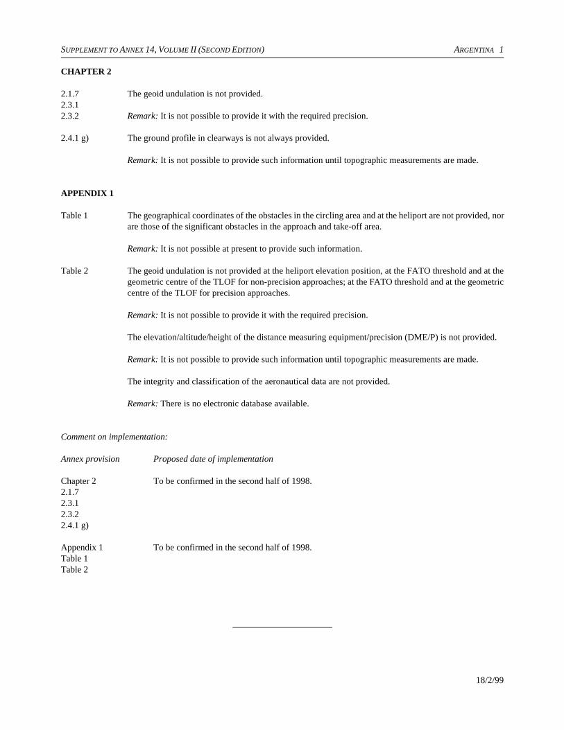
SUPPLEMENT TO ANNEX 14, VOLUME II (SECOND EDITION) ARGENTINA 1
18/2/99
CHAPTER 2
2.1.72.3.12.3.2
The geoid undulation is not provided.
Remark: It is not possible to provide it with the required precision.
2.4.1 g) The ground profile in clearways is not always provided.
Remark: It is not possible to provide such information until topographic measurements are made.
APPENDIX 1
Table 1 The geographical coordinates of the obstacles in the circling area and at the heliport are not provided, norare those of the significant obstacles in the approach and take-off area.
Remark: It is not possible at present to provide such information.
Table 2 The geoid undulation is not provided at the heliport elevation position, at the FATO threshold and at thegeometric centre of the TLOF for non-precision approaches; at the FATO threshold and at the geometriccentre of the TLOF for precision approaches.
Remark: It is not possible to provide it with the required precision.
The elevation/altitude/height of the distance measuring equipment/precision (DME/P) is not provided.
Remark: It is not possible to provide such information until topographic measurements are made.
The integrity and classification of the aeronautical data are not provided.
Remark: There is no electronic database available.
Comment on implementation:
Annex provision Proposed date of implementation
Chapter 2 To be confirmed in the second half of 1998.2.1.72.3.12.3.22.4.1 g)
Appendix 1 To be confirmed in the second half of 1998.Table 1Table 2

SUPPLEMENT TO ANNEX 14, VOLUME II (SECOND EDITION) AUSTRALIA 1
18/2/99
CHAPTER 3
3.1.3 The overall slope is not to exceed 7.5 degrees.
3.1.11 The landing and lift-off area (LLA equivalent to TLOF) should have an area equal in size to theundercarriage contact points plus one metre on all sides.
3.1.12 The overall slope of the LLA, in any direction, should not exceed the slope landing capability of thehelicopter.
3.1.14 Australian guidelines do not require a safety area.
Remark: Australian FATO is 2 times the overall length/width in lieu of 1.5 times the overall length/widthas required by Annex 14, Volume II.
3.1.34 Australian guidelines do not specify the dimensions of an air transit route.
CHAPTER 5
5.3.3.25.3.3.3*
The direction of approach should be indicated by at least two omnidirectional green lights or by one whitelead-in light.
5.3.6.2 The edge of the FATO should be defined by omnidirectional white lights spaced not more than eight metresapart or by a combination of markings and floodlighting. Where this is not practicable, the GEA should beso defined.
*Recommended Practice
SUPPLEMENT TO ANNEX 14, VOLUME II (SECOND EDITION) AUSTRIA 1
21/1/97
CHAPTER 2
2.1.1 The geographical coordinates are reported in Austria in degrees, minutes, seconds. Geographicalcoordinates with accuracy as defined in Annex 14 will be reported with application of the WGS-84 latestat 1 January 1998.
CHAPTER 3
3.1.2 For designing and classifying heliports no distrinction is made between performance classes of helicopters.
FATOs are divided into three classes by minimum length (diameter) requirement.
3.1.3 For designing and classifying heliports no distrinction is made between performance classes of helicopters.
FATOs are divided into three classes by minimum length (diameter) requirement.
3.2.2 For designing and classifying heliports no distrinction is made between performance classes of helicopters.
FATOs are divided into three classes by minimum length (diameter) requirement.

SUPPLEMENT TO ANNEX 14, VOLUME II (SECOND EDITION) CANADA 1
21/1/97
CHAPTER 3
3.1.37 The minimum clearance between a helicopter stand and an object or other aircraft stand may be reducedto 3 metres in Canada.
3.2.1 Canada makes provision for performance class 3 helicopter operations at elevated heliports. Thedimensions of the FATO at elevated heliports for performance class 3 helicopters is the same as that usedfor performance class 2 helicopters.
3.2.2 b) Canada makes provision for performance class 3 helicopter operations at elevated heliports. Thedimensions of the FATO at elevated heliports for performance class 3 helicopters is the same as that usedfor performance class 2 helicopters.
3.2.5 Canada does not require a safety area around the FATO of elevated heliports.
3.3.2 The FATO for single main rotor helicopters operating on helidecks within the inland waters of Canada shallbe of sufficient size to contain a circle of a diameter not less than the main rotor diameter of the designhelicopter.
3.4.1 The Canadian standards for the size of a FATO located at the bow or stern of a vessel for a single mainrotor helicopter requires the FATO to be of sufficient size to contain a circle with a diameter not less thanthe main rotor diameter of the design helicopter.
CHAPTER 5
5.2.3.3 Canada indicates the maximum allowable mass markings in thousands of pounds on the touchdown andlift-off area of elevated heliports and helidecks.
5.3.6.2 b) Canada requires a minimum of five lights to mark a circular FATO.
5.3.8.13 Canada permits the use of retro-reflective markers as the minimum lighting requirements at remoteheliports where it is impractical to provide lighting.

SUPPLEMENT TO ANNEX 14, VOLUME II (SECOND EDITION) CHILE 1
18/2/99
CHAPTER 2
2.3.1 The heliport elevation shall be measured and reported to the aeronautical information services authorityto the accuracy of one-half metre or foot.
Remark: Chilean authorities responsible for providing geodetic data have not yet determined WGS-84vertical reference data sufficient to obtain the geoid undulation. Therefore, once these authorities haveprovided that information, we shall be in a position to make the corresponding publications.
Note.C In view of the above, we are still waiting to adopt the Standards in which subjects arementioned relating to geoid elevation data, for example, paragraphs 2.1.7, 2.3.2, etc.

SUPPLEMENT TO ANNEX 14, VOLUME II (SECOND EDITION) FRANCE 1
18/2/99
CHAPTER 6
6.1 In France the minimum level of protection is assured at surface level heliports by a quantity of 50 kg ofpowder or equivalent and at elevated heliports by a quantity of 250 kg of powder or equivalent.

SUPPLEMENT TO ANNEX 14, VOLUME II (SECOND EDITION) GERMANY 1
18/2/99
CHAPTER 2
2.1.2 Full implementation of the quality system can only be achieved by the date indicated.2.1.32.1.4*
2.1.52.1.6
Publishing of the heliport reference points in WGS-84 will be an ongoing task for some time after the dateof applicability of Amendment 2.
APPENDIX 1
Table 1Table 2
In Germany the description of obstacles differs as follows from what is given in these tables.
a) Obstacles in the circling area for non-precision and turning departures and at the heliport.
b) Significant obstacles in the precision approach and straight departure area.
Table 2 The WGS-84 geoid undulation at heliport elevation position will not be published in Germany.
Remark: This item is not considered to be required for VFR heliports. As concerns potential German IFRheliports, the WGS-84 geoid undulation would always be published for the FATO threshold, TLOFgeometric centre. This would even apply for non-precision approaches because the MDH is also referredto this position.
Comment on implementation:
Annex provision Proposed date of implementation
Chapter 2 31 December 19982.1.22.1.32.1.4*
Appendix 5 It is not intended to comply with this provision.Table 1 andTable 2
*Recommended Practice

SUPPLEMENT TO ANNEX 14, VOLUME II (SECOND EDITION) GREECE 1
* Recommended Practice
21/1/97
CHAPTER 5
5.3.3.4* The approach lighting system provided for a non-precision final approach and take-off area is 90 metresin length.
5.3.3.6* The installation of steady lights of the heliports regarding their light distribution and intensity has beenrealized in compliance with the previous editions of Annex 14, Volume II.
SUPPLEMENT TO ANNEX 14, VOLUME II (SECOND EDITION) NETHERLANDS 1
18/2/99
CHAPTER 2
2.1.2 b) and c)2.4.22.4.3
In the Netherlands it is not yet considered necessary to determine the geographical coordinates of thegeometric centre of the touchdown and lift-off area, thresholds of the final approach and take-off area,centre line points of the helicopter ground taxiways, air taxiways and air transit routes and helicopter standsin terms of the World Geodetic System C 1984 (WGS-84) geodetic reference datum.
CHAPTER 3
3.1.18 The height limitation of 25 cm applies for helidecks and elevated heliports only. For ground level heliportsthe maximum height of objects permitted in the safety area shall not exceed 35 cm.
3.1.23 The separation distances between:C a helicopter-ground-taxiway and object shall not be less than 1x the greatest overall width of a
helicopter with rotor turning (centre line to object);C a helicopter-ground-taxiway and a helicopter stand shall not be less than 1x the greatest overall width
of a helicopter with rotor turning (centre line to edge).
3.1.33 The separation distance between:C an air-taxiway and another air-taxiway shall not be less than 3x the greatest width of a helicopter with
rotor turning (between centre lines);C an air-taxiway and a helicopter-ground-taxiway shall not be less than 3x the greatest width of a
helicopter with rotor turning (between centre lines);C an air-taxiway and a helicopter stand shall not be less than 1.5x the greatest width of a helicopter with
rotor turning (centre line to edge).
3.1.39 The separation distance between the edge of a runway strip and the edge of a FATO shall not be less than2x the overall length of the largest helicopter the FATO is intended to serve.
CHAPTER 4
4.2.5 The slopes for visual approach and visual take-off for Class 2 and Class 3 helicopters for the first sectionshall be 12.5 per cent.
CHAPTER 5
5.2.4.4 The height of the marker shall not exceed 35 cm above ground or snow level.

SUPPLEMENT TO ANNEX 14, VOLUME II (SECOND EDITION) NEW ZEALAND 1
18/2/99
CHAPTER 1
1.2 New Zealand has no heliports intended to be used by helicopters in international civil aviation.
New Zealand Civil Aviation Rules Part 139 prescribe rules governing the certification and operation ofaerodromes and rules for operators of aircraft using aerodromes.
No person shall operate an aerodrome serving any aeroplane having a certified seating capacity of morethan 30 passengers that is engaged in regular air transport operations except under the authority of, and inaccordance with the provisions of, an aerodrome operating certificate issued for that aerodrome under NewZealand Civil Aviation Rules Part 139.
Remark: An aerodrome operator who is not required to hold an aerodrome operating certificate may applyfor an aerodrome operating certificate.
New Zealand heliports are not required to be certificated.
Except for a person operating a helicopter on an external load operation, no person operating a helicoptershall use any place within a populous area as a heliport unless the heliport has physical characteristics,obstacle limitation surfaces and visual aids commensurate with the characteristics of the helicopter beingoperated and the ambient light conditions during operations, and the heliport is clear of all persons, animals,vehicles or other obstructions during the hover, touchdown or lift-off other than persons and vehiclesessential to the operation, and the selected approach and take-off paths are such that, if the helicopter is nota performance Class 1 helicopter, an autorotative landing can be conducted without any undue risk to anyperson on the ground, and the helicopter can be manoeuvred in the aerodrome traffic circuit clear of anyobstructions, and not in conflict with the aerodrome traffic circuit or instrument approach of any otheraerodrome.
Remark: New Zealand CAA Advisory Circular AC139-08 contains heliport design standards for heliportsin populous areas that are acceptable to the Director.
SUPPLEMENT TO ANNEX 14, VOLUME II (SECOND EDITION) NORWAY 1
18/2/99
CHAPTER 5
5.2.2.3 Markings shall be yellow in colour instead of white in colour.5.2.2.45.2.4.45.2.7.4
Remark: Yellow markings are used due to the need for improved visual references during the winter seasonwhen the heliport identifications are covered with ice and snow.
5.2.12.2 Air transit route markings are located along the edge of the air transit route only.5.2.13.2
Remark: The reason for this is due to the possible damage which markers along the centre line may causeif the helicopter is forced to a sudden touchdown.

SUPPLEMENT TO ANNEX 14, VOLUME II (SECOND EDITION) SPAIN 1
21/1/97
CHAPTER 2
2.1 At the present time, geographical coordinates indicating latitude and longitude are not expressed in termsof the WGS-84 system.

SUPPLEMENT TO ANNEX 14, VOLUME II (SECOND EDITION) SWEDEN 1
18/2/99
CHAPTER 4
4.2.8 The separation between the take-off climb surface and the approach surface is required to be 90 degreesor more, instead of 150 degrees.
APPENDIX 1
Table 1 to Comment on implementation:Table 5
For heliports with instrument approach procedures, Appendix 1, Tables 1-5 will be implemented on 23April 1997, except that obstacles in the circling area and in the outer parts (>3 km) of the approach andtake-off areas will have an accuracy of 30 m in latitude/longitude (Table 1) and 5 m in elevation (Table 2).Obstacle data not meeting the requirements of Appendix 1 will be identified with effect from 23 April 1998.For other heliports, the implementation of Appendix 1 is yet to be determined.

SUPPLEMENT TO ANNEX 14, VOLUME II (SECOND EDITION) UNITED ARAB EMIRATES 1
18/2/99
CHAPTER 2
2.1 CRC not yet implemented.
2.1.7 Geoid undulation information not available.2.3
Comment on implementation:
2.1 November 2000.2.1.72.3
CHAPTER 3
3.2.7 Frangible objects on some older structures do not meet new standards.
3.3.2 Some helidecks on older structures are of non-standard size.
CHAPTER 4
4.2.15 Some helidecks on older structures do not meet requirements for mobile obstacles.
CHAPTER 5
5.1.1.2 Some helidecks are not equipped with standard wind direction indicators.
5.3 Non-standard lighting systems are installed on some older helidecks.