aeroelastic analysis of a delta wing considering geometric ... · aeroelastic analysis of a delta...
TRANSCRIPT
Aeroelastic analysis of a delta wing considering geometricnonlinear behavior
Felipe Schaedler de AlmeidaGraduate Program in Civil EngineeringFederal University of Rio Grande do Sul
Armando Miguel AwruchGraduate Program in Civil EngineeringFederal University of Rio Grande do Sul
ABSTRACT
Application of a partitioned procedure for the aeroelasticanalysis of a delta wing immersed in a compressibleflow is presented in this work. Structural and flow simulations are performed with different codes using the FiniteElement Method (FEM). Geometrically nonlinear effects areincorporated to a triangular shell element with a corota-tional formulation. Compressible flow simulations are performed by the two-step explicit Taylor-Galerkin (T-G) methodemploying moving meshes based on the Arbitrary Lagrangian-Eulerian (ALE) formulation of the governing equations.Simple and efficient algorithms are adopted to deal with the information exchanged between non-matching meshes in thefluid-structure interface boundary and for the fluid mesh movement. The aeroelastic behavior of a steel delta wing due toflows with different dynamic pressures is investigated. Results compare very well with other numerical works, but goodagreement with respect to experimental data is only obtained for tests with moderated wing displacements.
Keywords: Finite elements, Nonlinear dynamics, Aeroelasticity
1 INTRODUCTION
Determination of the interaction of fluid flow and flexible structures is a fundamental require-ment in a growing number of engineering applications. Aeroelasticity is one of the most importantclasses of fluid-structure interaction (FSI) problems. It is particularly relevant for aeronautical de-signs, where structure is subjected to usually high speed air flow. This problem is characterized bya cyclic process where structure is deformed under aerodynamic forces and flow is modified due tochange of solid boundary caused by structural displacements. The aeroelastic analysis is concernedwith the significant mutual interaction among inertial, elastic and aerodynamic forces present in thosecases [1]. The importance of these interaction phenomenon increases as more light and slender struc-tures are obtained by the use of advanced materials and modern design techniques, adopted to achieveproject requirements.
The objective of a FSI analysis is to determine the behavior of fluid-structure coupled systemsubjected to perturbations of the initial configuration. Depending on flow conditions these perturba-tions may be damped or they may grow indefinitely, producing apotentially catastrophic phenomenon
1
IV International Symposium on Solid Mechanics - MecSol 2013April 18 - 19, 2013 - Porto Alegre - Brazil
known as flutter. Alternatively, structural vibration may be sustained with limited amplitude. Thisphenomenon is known as limit cycle oscillation (LCO) and it isassociated to the presence of nonlin-earity in fluid and structure [2].
This work deals specifically with the aeroelastic analysis of a cropped delta wing, formed bya steel plate, in a compressible flow, which is a good representation of flexible wings of modern un-manned combat aircrafts [3]. The problem analyzed here was experimentally investigated by [4] forflow conditions with fixed Mach number but with dynamic pressures varying form values where LCOstarts and growing until flutter takes place. Progressivelymore sophisticated approaches were usedin the works of [5], [3], [2] and [6] for the numerical simulation of this problem. The increment ofmodel complexity used for the FSI analysis enhanced simulation quality for cases with low amplitudeLCO. However, numerical tests underpredicted wing vibrations for flow conditions close to flutter.
The present work investigates the application of a proposednumerical scheme to the aeroelasticanalysis of the cropped delta wing studied by [4] and compare the results to previous numerical workson the same problem. The computational methods used for FSI analysis are presented in Section2.The improved serial staggered scheme (ISS) [7] is adopted to solve the coupled problem, allowingto use independent methods for the simulation of fluid and structure. Information is transferred influid-structure boundary interface by the node-projectionscheme [8], which showed to be efficientfor the problem solved.
The explicit two-step Taylor-Galerkin scheme is employed for the simulation of compress-ible flows using tetrahedral finite elements for fluid domain discretization. An algebraic scheme isadopted to define the fluid mesh motion for adaptation to moving boundary determined by structuredisplacements. This method is very simple and numerical efficient, but there is no prevention withrespect to excessive mesh distortion.
Structure is simulated using a triangular flat shell element[9] which is able to handle thin andmoderately thick sections of isotropic or laminated composite materials. Geometrical nonlinearityis incorporated by the element independent corotational formulation (EICR) [10]. The nonlinearstructural dynamic integration is performed by the implicit scheme called approximately energy-conserving corotational procedure (AECCP) [11].
2 COMPUTATIONAL METHOD
Theoretical aspects of computational methods adopted for solving FSI are briefly presented inthe following sections. Structural analysis and fluid dynamic simulation are independently discusseddue to partitioned nature of the FSI technique employed here.
2.1 Geometrically nonlinear structural dynamics
The finite element code implemented by [9] is adopted for the structural dynamic analysis.Spatial discretization is performed by 3-noded triangularshell elements with three translations andthree rotations as nodal degrees of freedom. The shell element is formed by a membrane element for-mulated by [12] and a plate element developed by [13]. Moderately thick shell of isotropic materialsor laminated composites can be considered and transverse shear deformation is taken into account bythe first order theory (FSDT).
Geometrically nonlinear behavior is incorporated in the analysis by applying the element inde-pendent corotational formulation (EICR) [10] to the shell element, which is originally obtained fromlinear formulations. The main characteristic of EICR is the complete separation of corotational filter-ing of the deformational displacements from the core element formulation. Arbitrary large rotationsand translations are correctly analyzed, but only small strain are allowed due to limitations of EICR
2
IV International Symposium on Solid Mechanics - MecSol 2013April 18 - 19, 2013 - Porto Alegre - Brazil
and core element formulation.For each element, variations of deformational displacements δpd in the attached corotational
system are obtained from variations of global displacements δd using the relation
δpd = HPTδd = Λ δd (1)
where the matrixΛ = HPT comprises three operations, namely: local to global reference systemtransformation given by matrixT, deformational displacements extraction by the projectormatrix Pand conversion of spin vectors (representing variation of rotations inδd) into additive rotations (usedin δpd for compatibility with local element formulation), which is performed by the matrixH andnecessary when large rotations are present. Detailed discussions on corotational theory are given inreferences [14, 11, 15].
Time integration is performed using the approximately energy-conserving corotational proce-dure (AECCP). This implicit scheme was developed by [11] as an approximation to the corotationalmid-point dynamic algorithm [16], and it was introduced in order to conserve the full energy of themechanical system. It is a class of mid-point algorithm which is constructed by equating the changeof total momentum of the body to the impulse of internal and external forces acting on the systemduring the time step [17]. The equilibrium equation is given by Eq.(2), where,∆φk, ∆φe and∆φi
are the kinetic, external and strain energy increments in the time step, respectively.
∆φk +∆φi +∆φe = (fTmas,m + fTi,m − fTe,m)∆d = gTm∆d = 0 (2)
fmas,m, fe,m andfi,m are the mid-point inertial, external and internal nodal element forces, respectively.The mid-point vectors form an equivalent force vectorgm that may vanish, approximately conservingthe total energy of the system. In each time step the advance is conducted by a predictor step followedby corrector iteractions in order to approachgm to zero, as described in [11] and [9]. The mid-pointequilibrium condition adopted in AECCP is particularly suitable for the application in fluid-structureanalysis with the partitioned scheme used in this work, which is described in Section2.3. Previousexperience in using AECCP for FSI analysis was reported by [18].
2.2 Computational fluid dynamics
In this work the unsteady compressible flow is modeled by the Euler equations, which are givenin vectorial form by
∂U
∂t+
∂F i
∂xi
= 0, (i = 1, 2, 3) (3)
whereU is the vector of conservation variables andF i is the vector of advective fluxes in thexi
coordinate direction. A previous work [3] showed that Euler equations are well suited to this problembecause viscous effects have low influence in the aeroelastic behavior of the cropped delta wing .For FSI analysis, flow equations must be integrated in a moving domain, which is accomplished byadopting the Arbitrary Lagrangian-Eulerian (ALE) description [19]. Based on ALE formulation Eq.(3) turns to
∂U
∂t= −
∂H i
∂xi
−
∂wi
∂xi
U , (i = 1, 2, 3) (4)
with H i = (F i − wiU ) andwi being the velocity of the reference domain in the direction of coordi-natexi.
3

IV International Symposium on Solid Mechanics - MecSol 2013April 18 - 19, 2013 - Porto Alegre - Brazil
The explicit two-step Taylor-Galerkin method [20] is adopted for the nonlinear fluid solution.This scheme results from discretizing time dimension by a Taylor series expansion ofU followed bythe spatial discretizations of the resulting system of partial differential equations using the FEM. TheTaylor series expansion ofU , which is assumed to be known at timen, results in
∆U = ∆t∂Un+1/2
∂t(5)
where∆U = Un+1−Un and
∂Un+1/2
∂t= −
∂Hn+1/2i
∂xi
−
∂wi
∂xi
Un+1/2 (6)
with Un+1/2 = Un + 0.5∆t∂Un
∂t.
The system of conservation equations given in Eq. (5)–(6) is decoupled, so that the spatialdiscretization using FEM can be applied to each equation separately, and it may be written in ageneral form as
∆u = ∆t
(
−
∂hn+1/2i
∂xi
−
∂wi
∂xi
un+1/2
)
(7)
Applying Galerkin method to Eq. (7), with u, hi andwi approximated by interpolation ofnodal values (u, hi andwi) using element shape functionsN and interpolatingun+1/2 by piecewiseconstant functionsP(e) gives, after integrating by parts,
∫
Ve
NNT dV ∆u = −∆t
∫
Ve
∂N
∂xi
(
hn+1/2i
)
dV
−∆t∂wi
∂xi
∫
Ve
NP(e) dV un+1/2 +∆t
∫
Ae
N(
hn+1/2i
)
ni dA
(8)
whereni is the component of the normal vector in the boundary of the domain. un+1/2 representsuevaluated in the center of the element in timen+1/2, which is explicitly defined by Eq. (9) in termsof known variables at timen when linear tetrahedron elements are adopted for spatial discretizationof the fluid domain
un+1/2 =
(
1−∆t
2
∂wi
∂xi
)
un−
∆t
2
∂NT
∂xi
hni (9)
Using linear tetrahedron elements also simplifies the integration in Eq. (8), which becomesexplicitly defined and it may be evaluated after solving Eq. (9) in the same loop over the elements[20, 21], improving the computational efficiency. The system of equations resulting from spatial andtemporal discretization is solved iteratively using the following equation
∆ui+1 = M−1L
(
r− M∆ui
)
+∆ui (10)
whereM andML are the consistent and lumped mass matrices, respectively,r is the vector resultingform the integrals in the right hand side of Eq. (10) and the tilde indicates a global array. Artificialdissipation [22] is introduced in order to prevent oscillations of flow fields, which may occur in theproximity of shock regions due to numerical instabilities [23]. The size of the time steps is limitedby Courant-Friedrichs-Lewy condition (CFL), as it is usual inexplicit schemes.
4
IV International Symposium on Solid Mechanics - MecSol 2013April 18 - 19, 2013 - Porto Alegre - Brazil
In FEM analysis of FSI problems the mesh must move in order to accommodate the deflectionsof the flexible bodies that determine part of the boundary of the fluid domain. The mesh velocityfield is independent with respect to fluid motion and must be defined by a separate formulation. Inthis work a very simple algebraic scheme is adopted for this purpose. The velocity of a given internalnodei of the fluid mesh is determined by the velocity of the closest fluid nodej lying in the movingboundary belonging to the structure. It is given by the following expression
wi =
(
aijaij + aik
)
wj (11)
whereaij = (dij)−m is a coefficient determined by the distancedij form the internal nodei to a node
j in the moving boundary whileaik depends on the distance to the closest node in the fixed portionof the boundary. The exponentm determines the variation of influence of boundary velocity over themesh velocity in the interior of the domain, being adopted as3 in all problems solved in this work.
2.3 Fluid-structure interaction
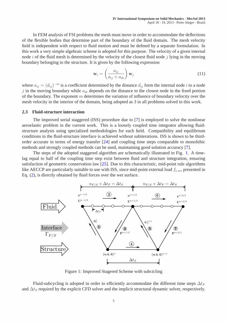
The improved serial staggered (ISS) procedure due to [7] is employed to solve the nonlinearaeroelastic problem in the current work. This is a loosely coupled time integrator allowing fluid-structure analysis using specialized methodologies for each field. Compatibility and equilibriumconditions in the fluid-structure interface is achieved without subiterations. ISS is shown to be third-order accurate in terms of energy transfer [24] and coupling time steps comparable to monolithicmethods and strongly coupled methods can be used, maintaining good solution accuracy [7].
The steps of the adopted staggered algorithm are schematically illustrated in Fig. 1. A time-lag equal to half of the coupling time step exist between fluidand structure integration, ensuringsatisfaction of geometric conservation law [25]. Due to this characteristic, mid-point rule algorithmslike AECCP are particularly suitable to use with ISS, since mid-point external loadfe,m, presented inEq. (2), is directly obtained by fluid forces over the wet surface.
Figure 1: Improved Stagered Scheme with subcicling
Fluid-subcycling is adopted in order to efficiently accommodate the different time steps∆tFand∆tS required by the explicit CFD solver and the implicit structural dynamic solver, respectively.
5
IV International Symposium on Solid Mechanics - MecSol 2013April 18 - 19, 2013 - Porto Alegre - Brazil
A number of fluid time stepsnF/S = ∆tS/∆tF is performed for each coupling time step, which istaken equal to∆tS.
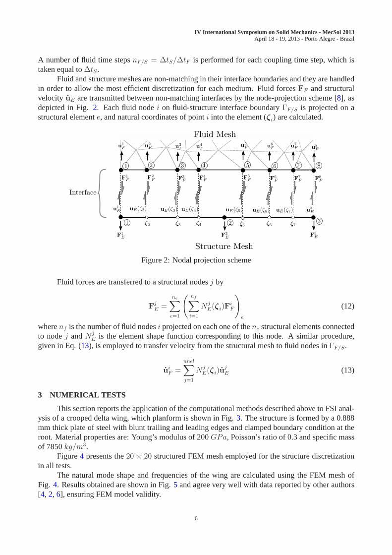
Fluid and structure meshes are non-matching in their interface boundaries and they are handledin order to allow the most efficient discretization for each medium. Fluid forcesFF and structuralvelocity uE are transmitted between non-matching interfaces by the node-projection scheme [8], asdepicted in Fig.2. Each fluid nodei on fluid-structure interface boundaryΓF/S is projected on astructural elemente, and natural coordinates of pointi into the element (ζi) are calculated.
Figure 2: Nodal projection scheme
Fluid forces are transferred to a structural nodesj by
FjE =
ne∑
e=1
(
nf∑
i=1
N jE(ζi)F
iF
)
e
(12)
wherenf is the number of fluid nodesi projected on each one of thene structural elements connectedto nodej andN j
E is the element shape function corresponding to this node. A similar procedure,given in Eq. (13), is employed to transfer velocity from the structural meshto fluid nodes inΓF/S.
uiF =
nnel∑
j=1
N jE(ζi)u
jE (13)
3 NUMERICAL TESTS
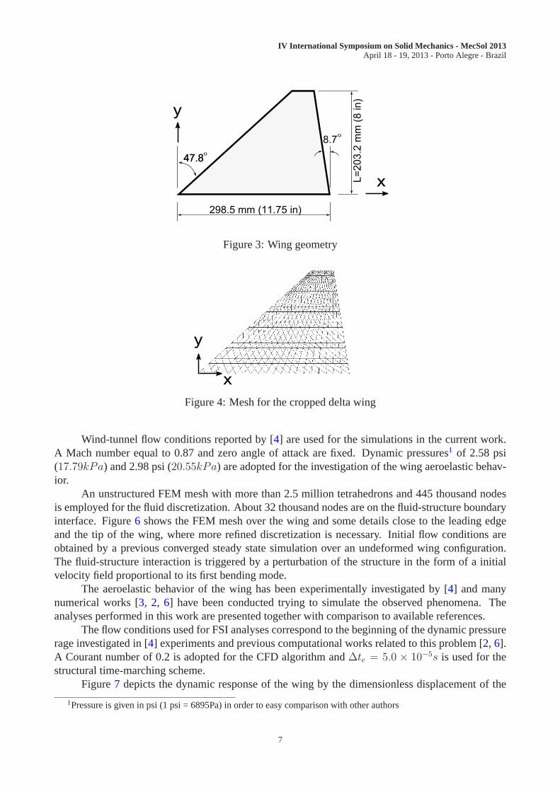
This section reports the application of the computational methods described above to FSI anal-ysis of a crooped delta wing, which planform is shown in Fig.3. The structure is formed by a 0.888mm thick plate of steel with blunt trailing and leading edgesand clamped boundary condition at theroot. Material properties are: Young’s modulus of 200GPa, Poisson’s ratio of 0.3 and specific massof 7850kg/m3.
Figure4 presents the20 × 20 structured FEM mesh employed for the structure discretizationin all tests.
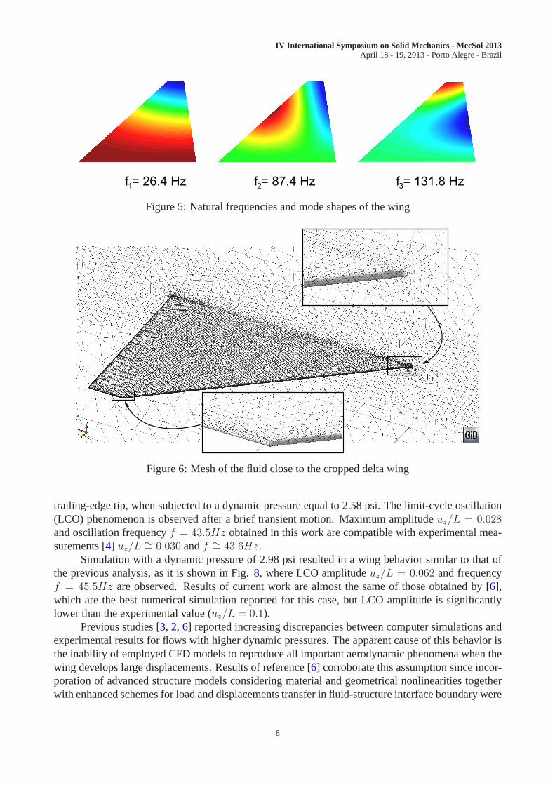
The natural mode shape and frequencies of the wing are calculated using the FEM mesh ofFig. 4. Results obtained are shown in Fig.5 and agree very well with data reported by other authors[4, 2, 6], ensuring FEM model validity.
6
IV International Symposium on Solid Mechanics - MecSol 2013April 18 - 19, 2013 - Porto Alegre - Brazil
x
y
47.8o
47.8
8.7o
298.5 mm (11.75 in)
L=
20
3.2
mm
(8
in
)
Figure 3: Wing geometry
x
y
Figure 4: Mesh for the cropped delta wing
Wind-tunnel flow conditions reported by [4] are used for the simulations in the current work.A Mach number equal to 0.87 and zero angle of attack are fixed. Dynamic pressures1 of 2.58 psi(17.79kPa) and 2.98 psi (20.55kPa) are adopted for the investigation of the wing aeroelastic behav-ior.
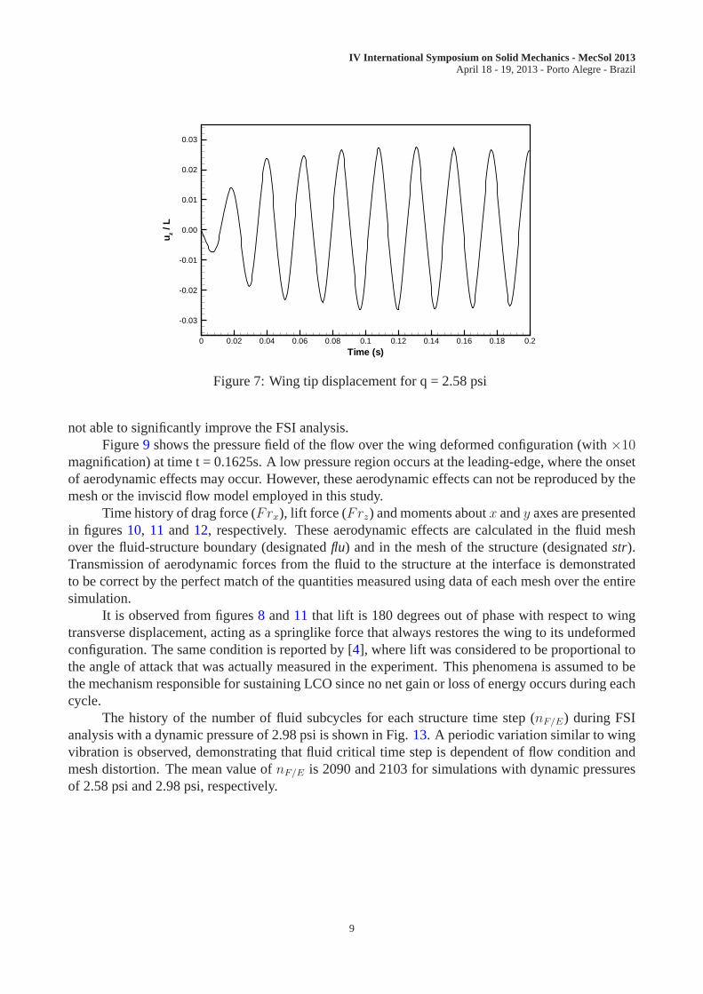
An unstructured FEM mesh with more than 2.5 million tetrahedrons and 445 thousand nodesis employed for the fluid discretization. About 32 thousand nodes are on the fluid-structure boundaryinterface. Figure6 shows the FEM mesh over the wing and some details close to the leading edgeand the tip of the wing, where more refined discretization is necessary. Initial flow conditions areobtained by a previous converged steady state simulation over an undeformed wing configuration.The fluid-structure interaction is triggered by a perturbation of the structure in the form of a initialvelocity field proportional to its first bending mode.
The aeroelastic behavior of the wing has been experimentally investigated by [4] and manynumerical works [3, 2, 6] have been conducted trying to simulate the observed phenomena. Theanalyses performed in this work are presented together withcomparison to available references.
The flow conditions used for FSI analyses correspond to the beginning of the dynamic pressurerage investigated in [4] experiments and previous computational works related to this problem [2, 6].A Courant number of 0.2 is adopted for the CFD algorithm and∆te = 5.0 × 10⁻⁵s is used for thestructural time-marching scheme.
Figure7 depicts the dynamic response of the wing by the dimensionless displacement of the
1Pressure is given in psi (1 psi = 6895Pa) in order to easy comparison with other authors
7
IV International Symposium on Solid Mechanics - MecSol 2013April 18 - 19, 2013 - Porto Alegre - Brazil
f = 26.4 Hz1
f = 87.4 Hz2
f = 131.8 Hz3
Figure 5: Natural frequencies and mode shapes of the wing
Figure 6: Mesh of the fluid close to the cropped delta wing
trailing-edge tip, when subjected to a dynamic pressure equal to 2.58 psi. The limit-cycle oscillation(LCO) phenomenon is observed after a brief transient motion.Maximum amplitudeuz/L = 0.028and oscillation frequencyf = 43.5Hz obtained in this work are compatible with experimental mea-surements [4] uz/L ∼= 0.030 andf ∼= 43.6Hz.
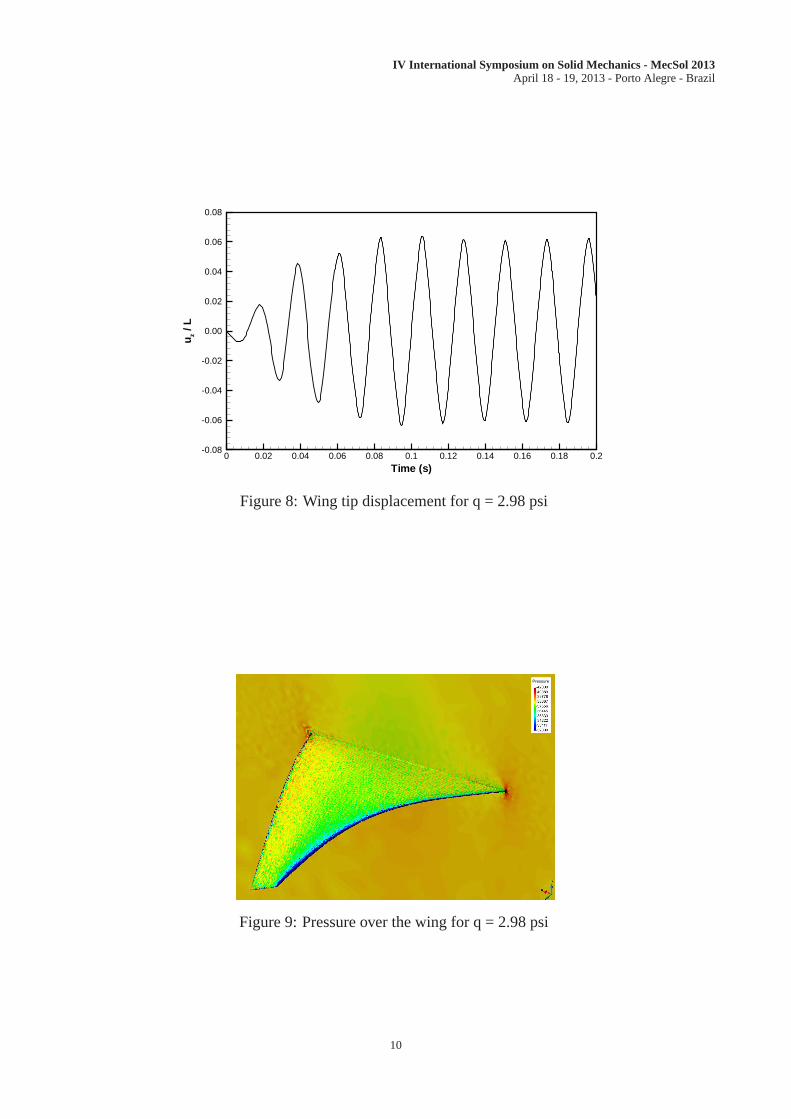
Simulation with a dynamic pressure of 2.98 psi resulted in a wing behavior similar to that ofthe previous analysis, as it is shown in Fig.8, where LCO amplitudeuz/L = 0.062 and frequencyf = 45.5Hz are observed. Results of current work are almost the same of those obtained by [6],which are the best numerical simulation reported for this case, but LCO amplitude is significantlylower than the experimental value (uz/L = 0.1).
Previous studies [3, 2, 6] reported increasing discrepancies between computer simulations andexperimental results for flows with higher dynamic pressures. The apparent cause of this behavior isthe inability of employed CFD models to reproduce all important aerodynamic phenomena when thewing develops large displacements. Results of reference [6] corroborate this assumption since incor-poration of advanced structure models considering material and geometrical nonlinearities togetherwith enhanced schemes for load and displacements transfer in fluid-structure interface boundary were
8
IV International Symposium on Solid Mechanics - MecSol 2013April 18 - 19, 2013 - Porto Alegre - Brazil
Time (s)
u z/L
0 0.02 0.04 0.06 0.08 0.1 0.12 0.14 0.16 0.18 0.2
-0.03
-0.02
-0.01
0.00
0.01
0.02
0.03
Figure 7: Wing tip displacement for q = 2.58 psi
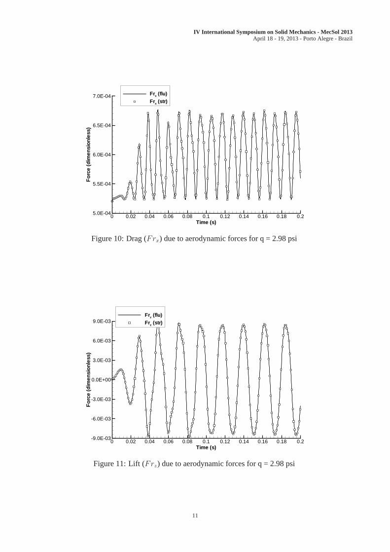
not able to significantly improve the FSI analysis.Figure9 shows the pressure field of the flow over the wing deformed configuration (with×10
magnification) at time t = 0.1625s. A low pressure region occurs at the leading-edge, where the onsetof aerodynamic effects may occur. However, these aerodynamic effects can not be reproduced by themesh or the inviscid flow model employed in this study.
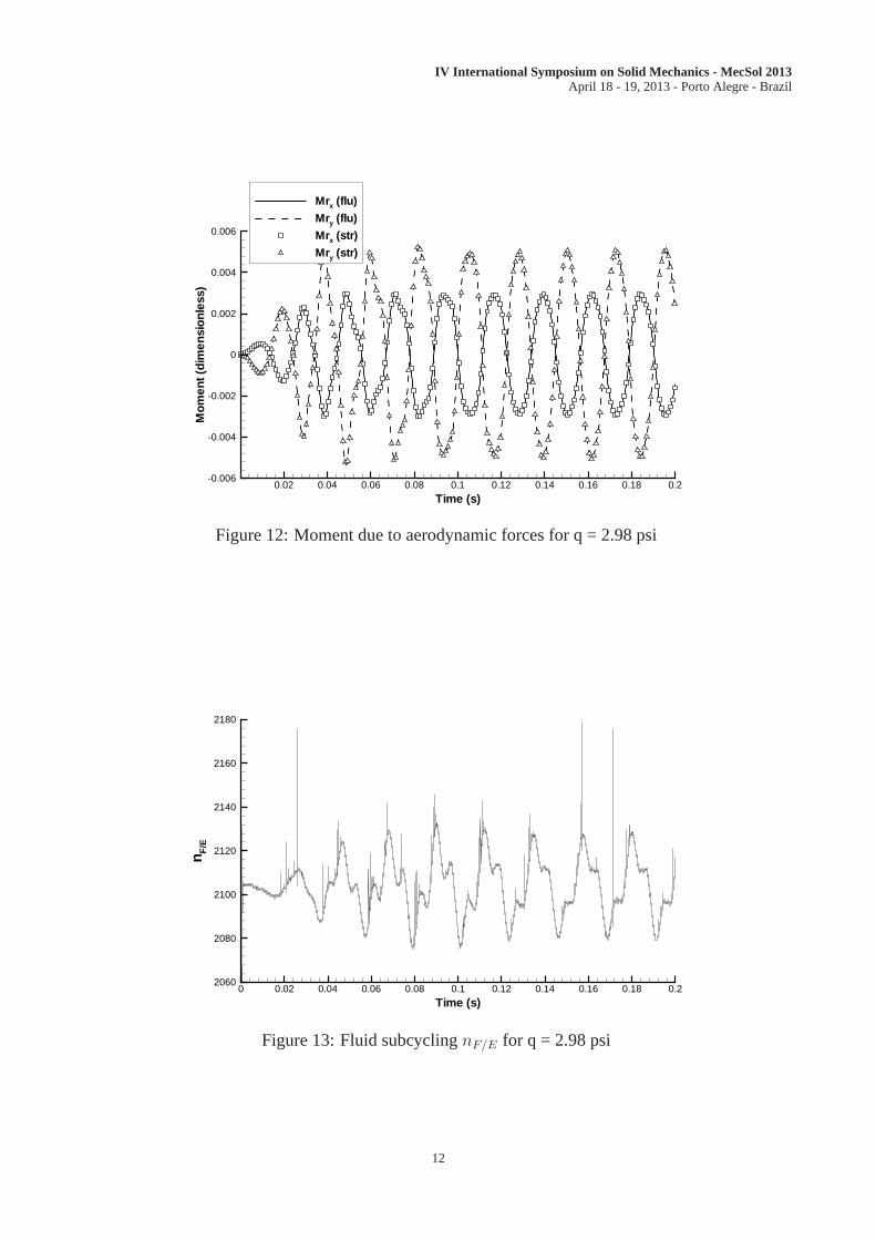
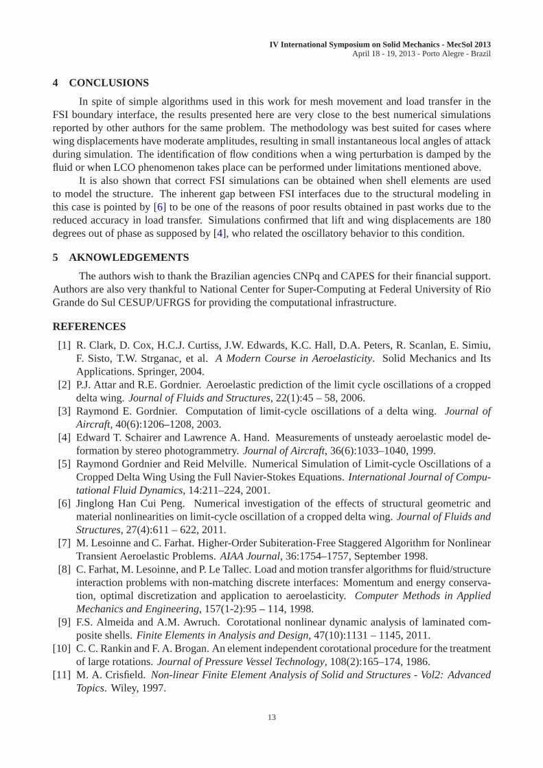
Time history of drag force (Frx), lift force (Frz) and moments aboutx andy axes are presentedin figures10, 11 and12, respectively. These aerodynamic effects are calculated in the fluid meshover the fluid-structure boundary (designatedflu) and in the mesh of the structure (designatedstr).Transmission of aerodynamic forces from the fluid to the structure at the interface is demonstratedto be correct by the perfect match of the quantities measuredusing data of each mesh over the entiresimulation.
It is observed from figures8 and11 that lift is 180 degrees out of phase with respect to wingtransverse displacement, acting as a springlike force thatalways restores the wing to its undeformedconfiguration. The same condition is reported by [4], where lift was considered to be proportional tothe angle of attack that was actually measured in the experiment. This phenomena is assumed to bethe mechanism responsible for sustaining LCO since no net gain or loss of energy occurs during eachcycle.
The history of the number of fluid subcycles for each structure time step (nF/E) during FSIanalysis with a dynamic pressure of 2.98 psi is shown in Fig.13. A periodic variation similar to wingvibration is observed, demonstrating that fluid critical time step is dependent of flow condition andmesh distortion. The mean value ofnF/E is 2090 and 2103 for simulations with dynamic pressuresof 2.58 psi and 2.98 psi, respectively.
9
IV International Symposium on Solid Mechanics - MecSol 2013April 18 - 19, 2013 - Porto Alegre - Brazil
Time (s)
u z/L
0 0.02 0.04 0.06 0.08 0.1 0.12 0.14 0.16 0.18 0.2-0.08
-0.06
-0.04
-0.02
0.00
0.02
0.04
0.06
0.08
Figure 8: Wing tip displacement for q = 2.98 psi
Pressure
Figure 9: Pressure over the wing for q = 2.98 psi
10
IV International Symposium on Solid Mechanics - MecSol 2013April 18 - 19, 2013 - Porto Alegre - Brazil
Time (s)
For
ce(d
imen
sion
less
)
0 0.02 0.04 0.06 0.08 0.1 0.12 0.14 0.16 0.18 0.25.0E-04
5.5E-04
6.0E-04
6.5E-04
7.0E-04 Frx (flu)
Frx (str)
Figure 10: Drag (Frx) due to aerodynamic forces for q = 2.98 psi
Time (s)
For
ce(d
imen
sion
less
)
0 0.02 0.04 0.06 0.08 0.1 0.12 0.14 0.16 0.18 0.2-9.0E-03
-6.0E-03
-3.0E-03
0.0E+00
3.0E-03
6.0E-03
9.0E-03Frz (flu)
Frz (str)
Figure 11: Lift (Frz) due to aerodynamic forces for q = 2.98 psi
11
IV International Symposium on Solid Mechanics - MecSol 2013April 18 - 19, 2013 - Porto Alegre - Brazil
Time (s)
Mom
ent(
dim
ensi
onle
ss)
0.02 0.04 0.06 0.08 0.1 0.12 0.14 0.16 0.18 0.2-0.006
-0.004
-0.002
0
0.002
0.004
0.006
Mrx (flu)
Mry (flu)
Mrx (str)
Mry (str)
Figure 12: Moment due to aerodynamic forces for q = 2.98 psi
Time (s)
n F/E
0 0.02 0.04 0.06 0.08 0.1 0.12 0.14 0.16 0.18 0.22060
2080
2100
2120
2140
2160
2180
Figure 13: Fluid subcyclingnF/E for q = 2.98 psi
12
IV International Symposium on Solid Mechanics - MecSol 2013April 18 - 19, 2013 - Porto Alegre - Brazil
4 CONCLUSIONS
In spite of simple algorithms used in this work for mesh movement and load transfer in theFSI boundary interface, the results presented here are veryclose to the best numerical simulationsreported by other authors for the same problem. The methodology was best suited for cases wherewing displacements have moderate amplitudes, resulting insmall instantaneous local angles of attackduring simulation. The identification of flow conditions when a wing perturbation is damped by thefluid or when LCO phenomenon takes place can be performed underlimitations mentioned above.
It is also shown that correct FSI simulations can be obtainedwhen shell elements are usedto model the structure. The inherent gap between FSI interfaces due to the structural modeling inthis case is pointed by [6] to be one of the reasons of poor results obtained in past works due to thereduced accuracy in load transfer. Simulations confirmed that lift and wing displacements are 180degrees out of phase as supposed by [4], who related the oscillatory behavior to this condition.
5 AKNOWLEDGEMENTS
The authors wish to thank the Brazilian agencies CNPq and CAPES for their financial support.Authors are also very thankful to National Center for Super-Computing at Federal University of RioGrande do Sul CESUP/UFRGS for providing the computational infrastructure.
REFERENCES
[1] R. Clark, D. Cox, H.C.J. Curtiss, J.W. Edwards, K.C. Hall, D.A. Peters, R. Scanlan, E. Simiu,F. Sisto, T.W. Strganac, et al.A Modern Course in Aeroelasticity. Solid Mechanics and ItsApplications. Springer, 2004.
[2] P.J. Attar and R.E. Gordnier. Aeroelastic prediction of the limit cycle oscillations of a croppeddelta wing.Journal of Fluids and Structures, 22(1):45 – 58, 2006.
[3] Raymond E. Gordnier. Computation of limit-cycle oscillations of a delta wing. Journal ofAircraft, 40(6):1206–1208, 2003.
[4] Edward T. Schairer and Lawrence A. Hand. Measurements ofunsteady aeroelastic model de-formation by stereo photogrammetry.Journal of Aircraft, 36(6):1033–1040, 1999.
[5] Raymond Gordnier and Reid Melville. Numerical Simulationof Limit-cycle Oscillations of aCropped Delta Wing Using the Full Navier-Stokes Equations.International Journal of Compu-tational Fluid Dynamics, 14:211–224, 2001.
[6] Jinglong Han Cui Peng. Numerical investigation of the effects of structural geometric andmaterial nonlinearities on limit-cycle oscillation of a cropped delta wing.Journal of Fluids andStructures, 27(4):611 – 622, 2011.
[7] M. Lesoinne and C. Farhat. Higher-Order Subiteration-Free Staggered Algorithm for NonlinearTransient Aeroelastic Problems.AIAA Journal, 36:1754–1757, September 1998.
[8] C. Farhat, M. Lesoinne, and P. Le Tallec. Load and motion transfer algorithms for fluid/structureinteraction problems with non-matching discrete interfaces: Momentum and energy conserva-tion, optimal discretization and application to aeroelasticity. Computer Methods in AppliedMechanics and Engineering, 157(1-2):95 – 114, 1998.
[9] F.S. Almeida and A.M. Awruch. Corotational nonlinear dynamic analysis of laminated com-posite shells.Finite Elements in Analysis and Design, 47(10):1131 – 1145, 2011.
[10] C. C. Rankin and F. A. Brogan. An element independent corotational procedure for the treatmentof large rotations.Journal of Pressure Vessel Technology, 108(2):165–174, 1986.
[11] M. A. Crisfield. Non-linear Finite Element Analysis of Solid and Structures -Vol2: AdvancedTopics. Wiley, 1997.
13
IV International Symposium on Solid Mechanics - MecSol 2013April 18 - 19, 2013 - Porto Alegre - Brazil
[12] Carlos A. Felippa. A study of optimal membrane triangleswith drilling freedoms.ComputerMethods in Applied Mechanics and Engineering, 192(16-18):2125 – 2168, 2003.
[13] Y.X. Zhang and K.S. Kim. A simple displacement-based 3-node triangular element for linearand geometrically nonlinear analysis of laminated composite plates. Computer Methods inApplied Mechanics and Engineering, 194(45-47):4607 – 4632, 2005.
[14] C.A. Felippa and B. Haugen. A unified formulation of small-strain corotational finite elements:I. theory. Computer Methods in Applied Mechanics and Engineering, Vol.194(21-24):2285 –2335, 2005.
[15] B. Nour-Omid and C. C. Rankin. Finite rotation analysis and consistent linearization usingprojectors. Computer Methods in Applied Mechanics and Engineering, Vol.93(3):353 – 384,1991.
[16] M.A. Crisfield and J. Shi. Co-rotational element/time-integration strategy for non-linear dy-namics.International Journal for Numerical Methods in Engineering, Vol.37(11):1897 – 1913,1994.
[17] M.A. Crisfield, U. Galvanetto, and G. Jelenic. Dynamics of 3-d co-rotational beams.Computa-tional Mechanics, Vol.20(6):507 – 519, 1997.
[18] A. Relvas and A. Suleman. Fluid-structure interaction modelling of nonlinear aeroelastic struc-tures using the finite element corotational theory.Journal of Fluids and Structures, 22(1):59 –75, 2006.
[19] Thomas J.R. Hughes, Wing Kam Liu, and Thomas K. Zimmermann. Lagrangian-eulerian finiteelement formulation for incompressible viscous flows.Computer Methods in Applied Mechan-ics and Engineering, 29(3):329 – 349, 1981.
[20] O.C. Zienkiewicz, R.L. Taylor, and P. Nithiarasu.The Finite Element Method For Fluid Dy-namics. The Finite Element Method. Elsevier Butterworth-Heinemann, 2005.
[21] P.R. Lohner. Applied Computational Fluid Dynamics Techniques: An Introduction Based onFinite Element Methods. John Wiley & Sons, 2001.
[22] P. Nithiarasu, O.C. Zienkiewicz, Satya Sai, B.V.K., K. Morgan, R. Codina, and M. VÃazquez.Shock capturing viscosities for the general fluid mechanicsalgorithm.International Journal forNumerical Methods in Fluids, 28(9):1325–1353, 1998.
[23] J. Argyris, I.St. Doltsinis, and H. Friz. Studies on computational reentry aerodynamics.Com-puter Methods in Applied Mechanics and Engineering, 81(3):257–289, 1990.
[24] Serge Piperno and Charbel Farhat. Partitioned procedures for the transient solution of cou-pled aeroelastic problems - part ii: energy transfer analysis and three-dimensional applications.Computer Methods in Applied Mechanics and Engineering, 190(24-25):3147 – 3170, 2001.
[25] C. Farhat and M. Lesoinne. Two efficient staggered algorithms for the serial and parallel solutionof three-dimensional nonlinear transient aeroelastic problems. Computer Methods in AppliedMechanics and Engineering, 182(3-4):499 – 515, 2000.
14