aeroelastic tailoring using additively manufactured …...aeroelastic tailoring using additively...
TRANSCRIPT
Aeroelastic Tailoring using
Additively Manufactured Lattice Structures
Max M. J. Opgenoord∗ and Karen E. Willcox†
Massachusetts Institute of Technology, Cambridge, MA, 02139
Lattice structures are of interest to the aerospace industry due to their high specificstiffness and the large design freedom that they offer. For instance, this large designfreedom can be used to aeroelastically tailor the structure to mitigate flutter. This paperdescribes a methodology for designing the internal structure of a wing as an additivelymanufactured lattice structure, while enforcing aeroelastic stability as a design constraint.A low-order model is developed for the dynamics of the lattice structure, which is thencoupled to a physics-based transonic flutter model to yield a complete aeroelastic model ofthe wing. The approach is demonstrated on a test case of a wing in transonic flow, whereit is shown that constraining the aeroelastic stability of the system adds only 3.5% weightwhile the flutter speed is increased by 3%.
Nomenclature
AΓ, AΓ, Aκ Coefficients of Γ evolution equationE Young’s modulusF Force vectorIy Mass moment of inertia per spanK Stiffness matrixL Lift per spanM Mass matrixM Mass per spanM∞ Freestream Mach numberMc/2 Aerodynamic moment per span
around mid-chordSy Mass unbalance per spanT()→() Map between low-order and full-order
lattice modelV⊥ Wing-perpendicular velocityVcruise Cruise speedVf Flutter speedaik Cross-sectional area of member con-
necting node i and kc Airfoil chord length
h Vertical deflection, positive downwardlik Length of member connecting node i
and kl Effective wing lengthm Number of members in latticen Number of nodes in latticet Timeu Displacement vectorw Vertical (downward) velocityx, y, z Coordinates aligned with swept wing
Symbols
Γ Circulation strengthθ Pitch angleλ Eigenvalueσ StressσC Maximum compressive stressσT Maximum tensile stressφ Basis functionχfl Maximum real eigenvalue of aeroelas-
tic system
I. Introduction
Novel manufacturing techniques open up additional design space for aerospace vehicles. High aspect ratiowings in novel aircraft concepts, for example, offer the benefits of higher aerodynamic efficiency, but
present the challenge of being more susceptible to aeroelastic problems such as flutter. Novel manufacturingtechniques present an opportunity to address this challenge via improved material properties (e.g., increasedstiffness) and also by enabling non-conventional internal wing layouts. This paper examines the possibility of
∗PhD Candidate, Department of Aeronautics and Astronautics, [email protected], Student Member AIAA†Professor of Aeronautics and Astronautics, [email protected], Associate Fellow AIAA
1 of 15
American Institute of Aeronautics and Astronautics
designing the internal structure of aircraft wings as a lattice structure, while mitigating flutter constraints.The fabrication of these lattice structures is enabled by advances in additive manufacturing technology.
To date, the aeroelastic optimization of aircraft wings has mostly focused on conventional internal wingstructures (i.e., an orthogonal array of ribs and spars).1–5 The structural efficiency of the wing can be fur-ther improved by using novel manufacturing techniques, which allow for moving away from the conventionalorthogonal rib-spar layout. Several ways to parametrize the internal structure of the wing have been demon-strated. For example, Balabanov and Haftka,6 and Locatelli et al.7 retained the rib-spar layout but allowedfor curvilinear components, which is therefore an inherently two-dimensional parametrization. Alternatively,three-dimensional parametrizations are used where the optimizer is allowed to place material anywhere inthe wing. These problems are typically solved using solid isotropic material with penalization (SIMP) meth-ods8,9 or level-set methods,10,11 as demonstrated by Kim et al.12 and James and Martins.13 A combinationof both methods is investigated by Stanford and Dunning14 where an orthogonal rib-spar layout is used butwhere topology optimization is applied to the ribs and spars. Aage et al. used topology optimization todesign the internal structure of an aircraft wing using giga-voxel resolution.15
Other studies have shown the potential benefits of novel manufacturing techniques on wing materialproperties. For example, Haddadpour et al.16 and Stodieck et al.17 demonstrated increased wing stiffnessfor tow-steering with composite materials.18,19 Stanford et al.20 investigated the differences between severalnovel tailoring schemes on wings subject to transonic flutter constraints and found that a spatially varyingthickness distribution—through additive manufacturing—yielded more benefit than tow-steering alone.
Aeroelastic optimization has also been conducted for helicopter and propeller blades. Ganguli et al.used high-fidelity flow and structural simulations to minimize rotor vibrations, while constraining aeroelasticstability.21 Glaz et al. developed a design methodology to minimize vibrations in forward flights, thistime using surrogate models for the structural and aerodynamic loads.22 Pagano et al. coupled aeroelasticsimulations to aeroacoustic evaluations for the design of propeller blades that minimize noise.23 In this work,however, we focus on aircraft wings and simply note that the design methodology could also be applied tohelicopter and propeller blades in the future, as they could also take advantage of lightweight aeroelasticallytailored lattice structures.
Lattice structures are of particular interest in aircraft design because of their high stiffness to weightratio.24 Walker et al. optimized the internal structure of a wing using lattice structures utilizing commercialsoftware.25 Lattice structures have also been used in morphing wing applications.26,27 In this paper we focuson an additively manufactured lattice structure as a possible solution to mitigating flutter in high aspectratio wings. These lattice structures are designed such that they are fine where stresses in the structure arehigh and coarse where the stresses are low, while still respecting flutter constraints. Furthermore, they aredesigned to be self-supporting by considering the manufacturing constraints directly in the optimization.
The paper is organized as follows. Section II discusses our design methodology for lattice structuresin detail, together with the aerodynamic model, as well as a low-order beam model from the full dynamiclattice model. Section III discusses the validation of this low-order beam model. Section IV demonstratesthe design methodology for a wing operating in transonic flow. The main findings are discussed in Section V.
II. Methodology
This section details the aeroelastic tailoring approach, which is summarized in Section II.A. Section II.Bexplains the flutter model used throughout this work. The structural model for the flutter model is de-scribed in detail in Section II.C. Section II.D describes the aeroelastic tailoring of a lattice structure throughoptimizing the cross-sectional area of each of the lattice’s members.
II.A. Aeroelastic Tailoring Approach
The complete aeroelastic tailoring approach can be summarized as follows. This work uses a physics-basedlow-order model for transonic flutter. The first step, therefore, is to calibrate the aerodynamic coefficients ofthat model using 2D unsteady Euler simulations for the airfoil family used in the wing design. This approachis described in detail in Ref. 28.
Second, the load distribution over the wing is computed to obtain the baseline lift coefficient c`0 at eachbeam section—which is needed to select the correct aerodynamic coefficients for the flutter model—and togenerate a pressure field over the wing that is subsequently used as input to the structural analysis of the wing
2 of 15
American Institute of Aeronautics and Astronautics
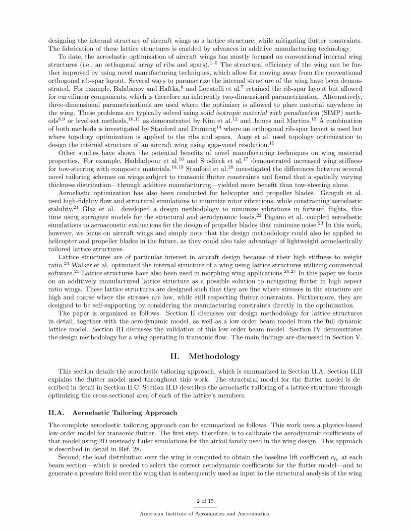
internal structure. There are several ways of computing the flow over the wing, e.g., using a vortex-latticemethod or a higher-fidelity Euler simulation. In the current work, we use a vortex-lattice method.
Initial geometry &loading condition
mises [Pa]
4000
3500
3000
2500
2000
1500
1000
500
Structural FEM resulton entire domain
Obtain metric fromstructural FEM andadapt that metric to
improve manufacturability Final backgroundlattice Final lattice
Figure 1. Approach for design of lattice structures for additive manufacturing.29
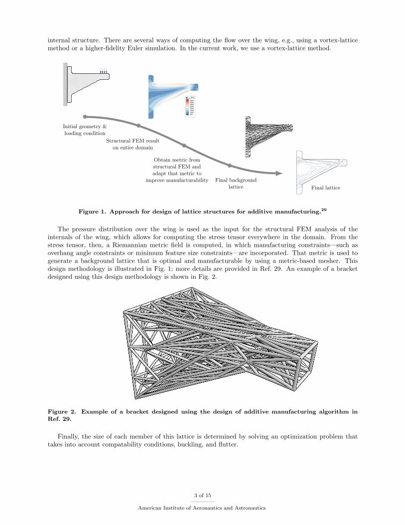
The pressure distribution over the wing is used as the input for the structural FEM analysis of theinternals of the wing, which allows for computing the stress tensor everywhere in the domain. From thestress tensor, then, a Riemannian metric field is computed, in which manufacturing constraints—such asoverhang angle constraints or minimum feature size constraints—are incorporated. That metric is used togenerate a background lattice that is optimal and manufacturable by using a metric-based mesher. Thisdesign methodology is illustrated in Fig. 1; more details are provided in Ref. 29. An example of a bracketdesigned using this design methodology is shown in Fig. 2.
Figure 2. Example of a bracket designed using the design of additive manufacturing algorithm inRef. 29.
Finally, the size of each member of this lattice is determined by solving an optimization problem thattakes into account compatability conditions, buckling, and flutter.
3 of 15
American Institute of Aeronautics and Astronautics
II.B. Flutter Model
We tailor the internal lattice structure of the wing such that the wing has minimum weight while miti-gating flutter, potentially at transonic flow conditions. At transonic Mach numbers, Theodorsen theorywith compressibility corrections is no longer accurate. Instead, we employ a physics-based low-order modelfor transonic flutter.28,30 This section briefly summarizes the physics-based model’s formulation; for moredetails, see Ref. 28 and 30.
This low-order flutter model is calibrated using 2D unsteady high-fidelity Euler simulations and validatedagainst standard flutter benchmark cases, where it is shown to accurately capture the characteristic transonicdip behavior. The model’s application to the flutter characteristics of wings is described in Ref. 30.
The aerodynamic model uses strip theory, which is applicable to high aspect ratio wings. For instance,at the ith section on the wing, the evolution equation for the circulation perturbation ∆Γi can be writtenas30
∆Γi =− AΓ
AΓ
∆Γi −AκAΓ
∆κx,i +1
AΓ
(∆wi + V⊥
∂∆hi∂yi
tan Λ
)
+V⊥AΓ
∆θi +ci/4
AΓ
(∆ωi + V⊥
∂∆θi∂yi
tan Λ
), (1)
where h is the (downward) deflection, w is the vertical (downward) velocity, θ is the pitch angle, ω is theangular velocity, c is the local chord, and V⊥ is the wing-perpendicular velocity. κx is the doublet strength,which is the second aerodynamic state per section. The aerodynamic coefficients AΓ, AΓ, Aκ are all calibratedfrom unsteady 2D transonic Euler simulations, as described in Ref. 28.
In Ref. 30, the flutter model is coupled to a one-dimensional Euler-Bernoulli beam model. Here, wereplace that beam model with a low-order lattice model, which is further described in Section II.C.
II.C. Low-Order Structural Model for Lattices
We can define a dynamic model for the displacement of each node in lattice, however, the resulting systemis potentially quite large and does not directly consider the vertical and angular displacement, which isneeded for the aerodynamic model. Therefore, we build a low-order structural model for the lattice, whichis described in detail here.
Consider a lattice with n nodes and m members. The dynamics of that lattice structure are describedby
M u(t) +Ku(t) = F(t), (2)
where M ∈ R3n×3n is a mass matrix, K ∈ R3n×3n is the stiffness matrix, F(t) ∈ R3n is a dynamic forcevector, and u(t) ∈ R3n is the displacement vector.
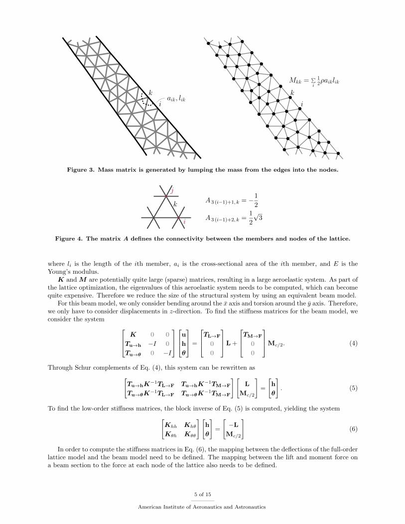
The mass matrix M is obtained by lumping half the weight of each member connecting to a node intothe mass of that node, while having massless connectors (Fig. 3).
The stiffness matrix K is obtained from the connectivity of the lattice and stress-strain relations,
K = AB−1AT (3)
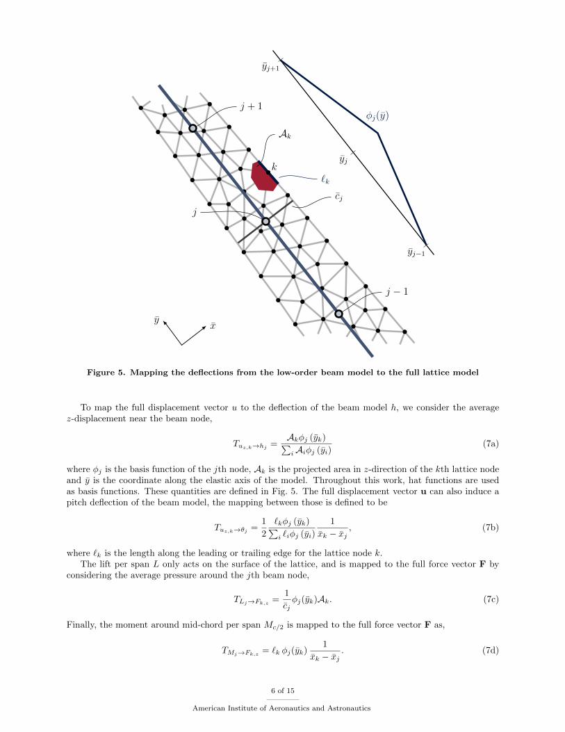
where A ∈ R3n×m and B ∈ Rm×m. Each column of A is the projection of a member of the lattice on thedegrees of freedom of the nodes on the lattice that are connected to that member (Fig. 4). For example thematrix entry corresponding to the ith node and jth member is expressed as,
A 3 (i−1)+1, j = nj · xA 3 (i−1)+2, j = nj · yA 3 (i−1)+3, j = nj · z.
B is a diagonal matrix where the ith diagonal entry corresponds to the deformation per unit force of the ithmember of the lattice,
Bii =liEai
,
4 of 15
American Institute of Aeronautics and Astronautics
k
iaik, lik
k
i
Mkk =∑
i
12ρaiklik
Figure 3. Mass matrix is generated by lumping the mass from the edges into the nodes.
j
i
kA 3 (i−1)+1, k = −1
2
A 3 (i−1)+2, k =1
2
√3
Figure 4. The matrix A defines the connectivity between the members and nodes of the lattice.
where li is the length of the ith member, ai is the cross-sectional area of the ith member, and E is theYoung’s modulus.K and M are potentially quite large (sparse) matrices, resulting in a large aeroelastic system. As part of
the lattice optimization, the eigenvalues of this aeroelastic system needs to be computed, which can becomequite expensive. Therefore we reduce the size of the structural system by using an equivalent beam model.
For this beam model, we only consider bending around the x axis and torsion around the y axis. Therefore,we only have to consider displacements in z-direction. To find the stiffness matrices for the beam model, weconsider the system
K 0 0
Tu→h −I 0
Tu→θ 0 −I
u
h
θ
=
TL→F
0
0
L +
TM→F
0
0
Mc/2. (4)
Through Schur complements of Eq. (4), this system can be rewritten as
[Tu→hK
−1TL→F Tu→hK−1TM→F
Tu→θK−1TL→F Tu→θK
−1TM→F
][L
Mc/2
]=
[h
θ
]. (5)
To find the low-order stiffness matrices, the block inverse of Eq. (5) is computed, yielding the system
[Khh Khθ
Kθh Kθθ
][h
θ
]=
[−LMc/2
](6)
In order to compute the stiffness matrices in Eq. (6), the mapping between the deflections of the full-orderlattice model and the beam model need to be defined. The mapping between the lift and moment force ona beam section to the force at each node of the lattice also needs to be defined.
5 of 15
American Institute of Aeronautics and Astronautics
j + 1
j
j − 1
k
yx
Ak
`k
yj−1
yj
yj+1
φj(y)
cj
Figure 5. Mapping the deflections from the low-order beam model to the full lattice model
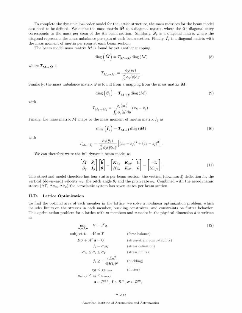
To map the full displacement vector u to the deflection of the beam model h, we consider the averagez-displacement near the beam node,
Tuz,k→hj=Akφj (yk)∑iAiφj (yi)
(7a)
where φj is the basis function of the jth node, Ak is the projected area in z-direction of the kth lattice nodeand y is the coordinate along the elastic axis of the model. Throughout this work, hat functions are usedas basis functions. These quantities are defined in Fig. 5. The full displacement vector u can also induce apitch deflection of the beam model, the mapping between those is defined to be
Tuz,k→θj =1
2
`kφj (yk)∑i `iφj (yi)
1
xk − xj, (7b)
where `k is the length along the leading or trailing edge for the lattice node k.The lift per span L only acts on the surface of the lattice, and is mapped to the full force vector F by
considering the average pressure around the jth beam node,
TLj→Fk,z=
1
cjφj(yk)Ak. (7c)
Finally, the moment around mid-chord per span Mc/2 is mapped to the full force vector F as,
TMj→Fk,z= `k φj(yk)
1
xk − xj. (7d)
6 of 15
American Institute of Aeronautics and Astronautics
To complete the dynamic low-order model for the lattice structure, the mass matrices for the beam modelalso need to be defined. We define the mass matrix M as a diagonal matrix, where the ith diagonal entrycorresponds to the mass per span of the ith beam section. Similarly, Sy is a diagonal matrix where the
diagonal represents the mass unbalance per span at each beam section. Finally, Iy is a diagonal matrix withthe mass moment of inertia per span at each beam section.
The beam model mass matrix M is found by yet another mapping,
diag(M)
= TM→M diag (M) (8)
where TM→M is
TMk→Mj=
φj(yk)∫ l
0φj(y)dy
.
Similarly, the mass unbalance matrix S is found from a mapping from the mass matrix M ,
diag(Sy
)= TM→S diag (M) (9)
with
TMk→Mj=
φj(yk)∫ l
0φj(y)dy
(xk − xj) .
Finally, the mass matrix M maps to the mass moment of inertia matrix Iy as
diag(Iy
)= TM→I diag (M) (10)
with
TMk→Ij =φj(yk)
∫ l0φj(y)dy
[(xk − xj)2
+ (zk − zj)2].
We can therefore write the full dynamic beam model as[M Sy
Sy Iy
][h
θ
]+
[Khh Khθ
Kθh Kθθ
][h
θ
]=
[−LMc/2
]. (11)
This structural model therefore has four states per beam section: the vertical (downward) deflection hi, thevertical (downward) velocity wi, the pitch angle θi and the pitch rate ωi. Combined with the aerodynamicstates (∆Γ, ∆κx, ∆κx) the aeroelastic system has seven states per beam section.
II.D. Lattice Optimization
To find the optimal area of each member in the lattice, we solve a nonlinear optimization problem, whichincludes limits on the stresses in each member, buckling constraints, and constraints on flutter behavior.This optimization problem for a lattice with m members and n nodes in the physical dimension d is writtenas
minu,a,f ,σ
V = lTa (12)
subject to Af = F (force balance)
Bσ +ATu = 0 (stress-strain compatability)
fi = σiai (stress definition)
−σC ≤ σi ≤ σT (stress limits)
fi ≥ −πEa2
i
4(Kli)2(buckling)
χfl < χfl,max (flutter)
amin,i ≤ ai ≤ amax,i
u ∈ Rnd, f ∈ Rm, σ ∈ Rm,
7 of 15
American Institute of Aeronautics and Astronautics
where ai is the cross-sectional area of the ith lattice member, fi is the force in the ith lattice member, σi isthe stress in the ith lattice member, and li is the length of the ith member. σT is the maximum allowabletensile stress and σC is the maximum allowable compressive stress. χfl is the maximum real part of theeigenvalues of the aeroelastic system, which is constrained to be lower than χfl,max (typically −0.005/s).Finally, K is the column effective length factor, which is taken to be 1.2 here.
Note that the optimization problem in Eq. (12) is nonconvex, if only because the constraint fi = σiaiis nonconvex. The problem is therefore solved using a generic NLP solver, in this case Ipopt.31 Suchlattice optimization problems are known to suffer from vanishing constraints,32 i.e., when the area ai→ 0,the relationship between fi and σi is no longer satisfied. However, this is not a problem in this work,because we set a minimum required area for each member of the lattice. This has been done to ensure themanufacturability of the lattice, as removal of members from the lattice could result in the lattice no longerbeing self-supporting.
III. Validation of Low-Order Structural Beam Model
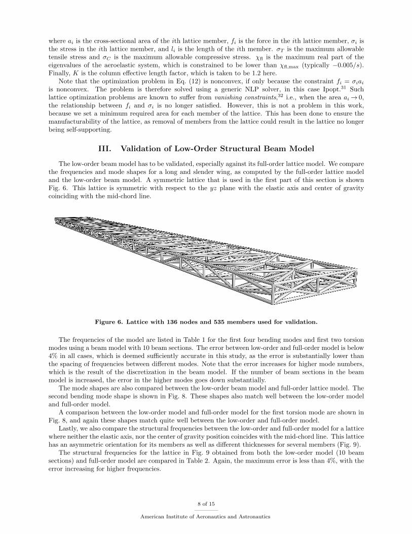
The low-order beam model has to be validated, especially against its full-order lattice model. We comparethe frequencies and mode shapes for a long and slender wing, as computed by the full-order lattice modeland the low-order beam model. A symmetric lattice that is used in the first part of this section is shownFig. 6. This lattice is symmetric with respect to the yz plane with the elastic axis and center of gravitycoinciding with the mid-chord line.
Figure 6. Lattice with 136 nodes and 535 members used for validation.
The frequencies of the model are listed in Table 1 for the first four bending modes and first two torsionmodes using a beam model with 10 beam sections. The error between low-order and full-order model is below4% in all cases, which is deemed sufficiently accurate in this study, as the error is substantially lower thanthe spacing of frequencies between different modes. Note that the error increases for higher mode numbers,which is the result of the discretization in the beam model. If the number of beam sections in the beammodel is increased, the error in the higher modes goes down substantially.
The mode shapes are also compared between the low-order beam model and full-order lattice model. Thesecond bending mode shape is shown in Fig. 8. These shapes also match well between the low-order modeland full-order model.
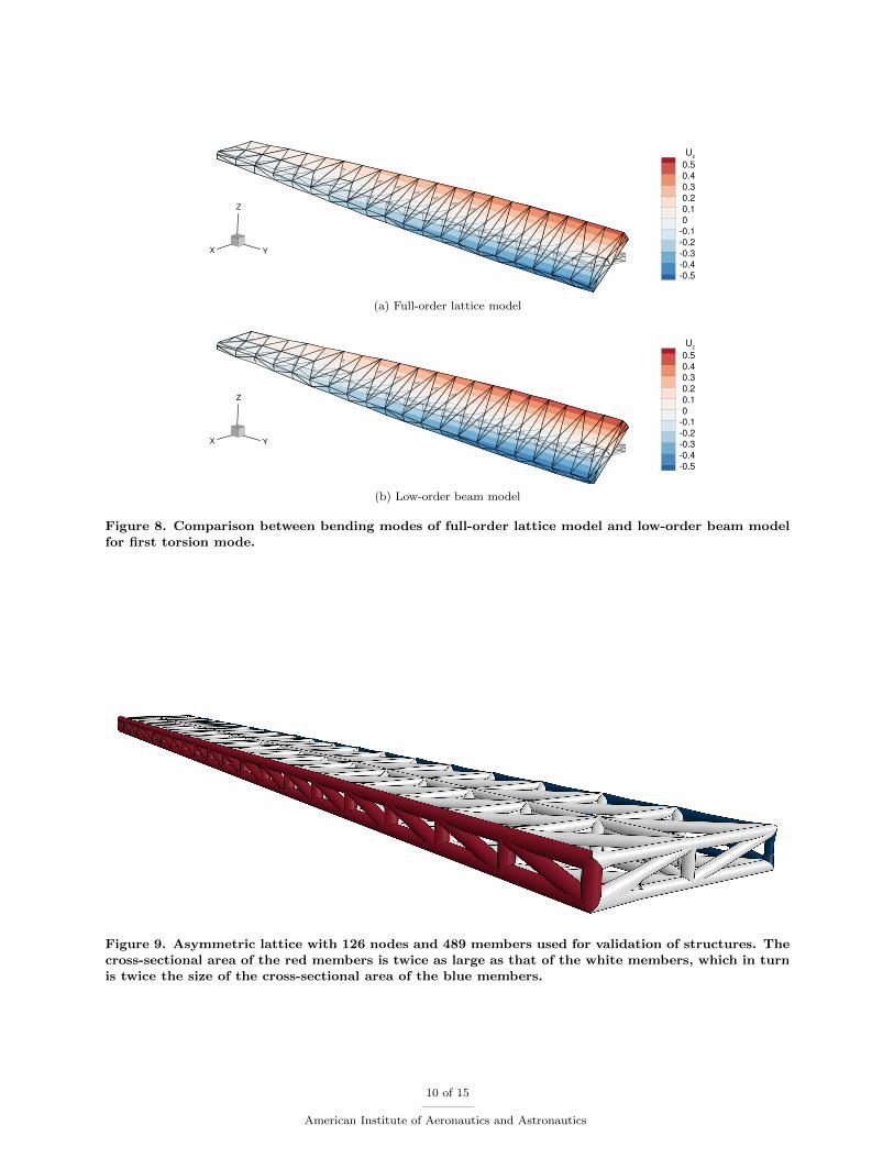
A comparison between the low-order model and full-order model for the first torsion mode are shown inFig. 8, and again these shapes match quite well between the low-order and full-order model.
Lastly, we also compare the structural frequencies between the low-order and full-order model for a latticewhere neither the elastic axis, nor the center of gravity position coincides with the mid-chord line. This latticehas an asymmetric orientation for its members as well as different thicknesses for several members (Fig. 9).
The structural frequencies for the lattice in Fig. 9 obtained from both the low-order model (10 beamsections) and full-order model are compared in Table 2. Again, the maximum error is less than 4%, with theerror increasing for higher frequencies.
8 of 15
American Institute of Aeronautics and Astronautics
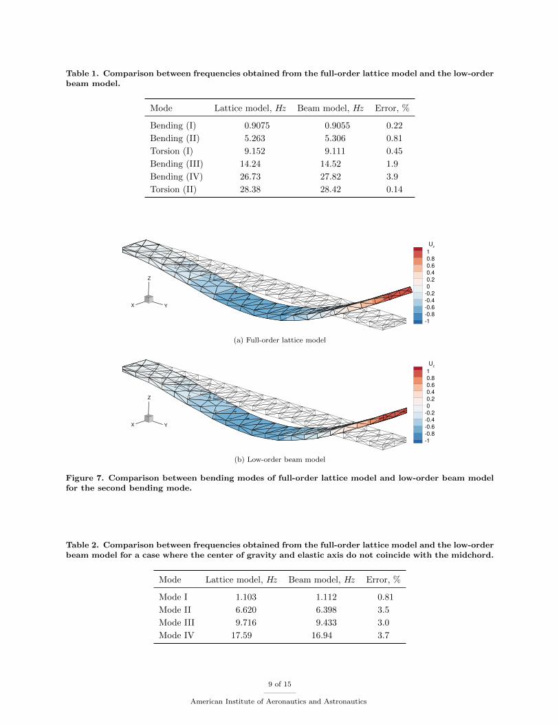
Table 1. Comparison between frequencies obtained from the full-order lattice model and the low-orderbeam model.
Mode Lattice model, Hz Beam model, Hz Error, %
Bending (I) 0.9075 0.9055 0.22
Bending (II) 5.263 5.306 0.81
Torsion (I) 9.152 9.111 0.45
Bending (III) 14.24 14.52 1.9
Bending (IV) 26.73 27.82 3.9
Torsion (II) 28.38 28.42 0.14
X Y
Z
Uz
1
0.8
0.6
0.4
0.2
0
0.2
0.4
0.6
0.8
1
(a) Full-order lattice model
X Y
Z
Uz
1
0.8
0.6
0.4
0.2
0
0.2
0.4
0.6
0.8
1
(b) Low-order beam model
Figure 7. Comparison between bending modes of full-order lattice model and low-order beam modelfor the second bending mode.
Table 2. Comparison between frequencies obtained from the full-order lattice model and the low-orderbeam model for a case where the center of gravity and elastic axis do not coincide with the midchord.
Mode Lattice model, Hz Beam model, Hz Error, %
Mode I 1.103 1.112 0.81
Mode II 6.620 6.398 3.5
Mode III 9.716 9.433 3.0
Mode IV 17.59 16.94 3.7
9 of 15
American Institute of Aeronautics and Astronautics
X Y
Z
Uz
0.5
0.4
0.3
0.2
0.1
0
0.1
0.2
0.3
0.4
0.5
(a) Full-order lattice model
X Y
Z
Uz
0.5
0.4
0.3
0.2
0.1
0
0.1
0.2
0.3
0.4
0.5
(b) Low-order beam model
Figure 8. Comparison between bending modes of full-order lattice model and low-order beam modelfor first torsion mode.
Figure 9. Asymmetric lattice with 126 nodes and 489 members used for validation of structures. Thecross-sectional area of the red members is twice as large as that of the white members, which in turnis twice the size of the cross-sectional area of the blue members.
10 of 15
American Institute of Aeronautics and Astronautics
IV. Flutter Mitigation through Aeroelastic Tailoring
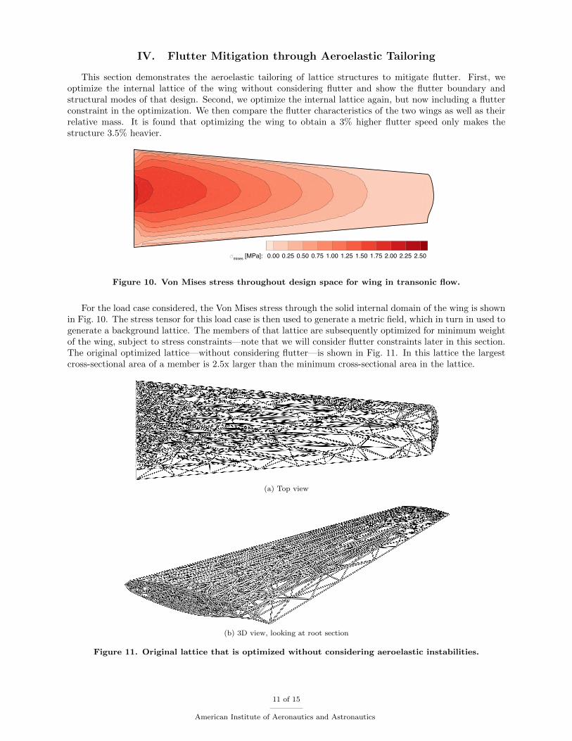
This section demonstrates the aeroelastic tailoring of lattice structures to mitigate flutter. First, weoptimize the internal lattice of the wing without considering flutter and show the flutter boundary andstructural modes of that design. Second, we optimize the internal lattice again, but now including a flutterconstraint in the optimization. We then compare the flutter characteristics of the two wings as well as theirrelative mass. It is found that optimizing the wing to obtain a 3% higher flutter speed only makes thestructure 3.5% heavier.
mises [MPa]: 0.00 0.25 0.50 0.75 1.00 1.25 1.50 1.75 2.00 2.25 2.50
Figure 10. Von Mises stress throughout design space for wing in transonic flow.
For the load case considered, the Von Mises stress through the solid internal domain of the wing is shownin Fig. 10. The stress tensor for this load case is then used to generate a metric field, which in turn in used togenerate a background lattice. The members of that lattice are subsequently optimized for minimum weightof the wing, subject to stress constraints—note that we will consider flutter constraints later in this section.The original optimized lattice—without considering flutter—is shown in Fig. 11. In this lattice the largestcross-sectional area of a member is 2.5x larger than the minimum cross-sectional area in the lattice.
(a) Top view
(b) 3D view, looking at root section
Figure 11. Original lattice that is optimized without considering aeroelastic instabilities.
11 of 15
American Institute of Aeronautics and Astronautics
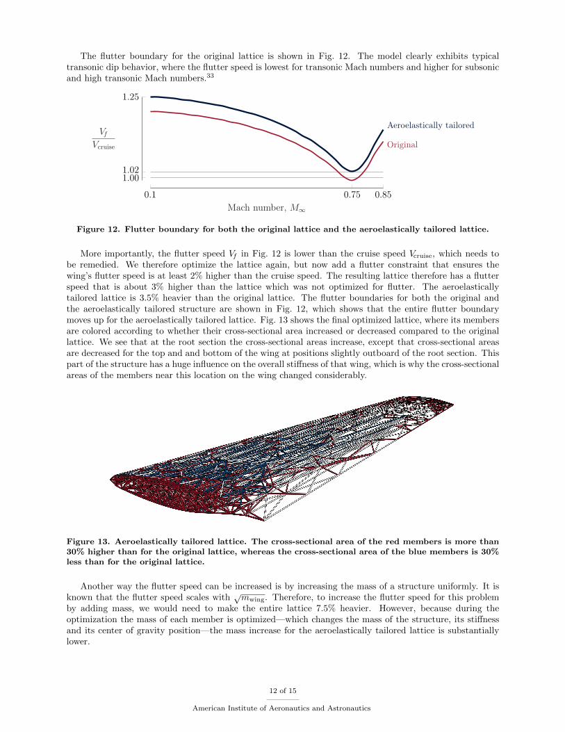
The flutter boundary for the original lattice is shown in Fig. 12. The model clearly exhibits typicaltransonic dip behavior, where the flutter speed is lowest for transonic Mach numbers and higher for subsonicand high transonic Mach numbers.33
0.1 0.75 0.85
1.00
1.25
1.02
Original
Aeroelastically tailored
Mach number, M∞
VfVcruise
Figure 12. Flutter boundary for both the original lattice and the aeroelastically tailored lattice.
More importantly, the flutter speed Vf in Fig. 12 is lower than the cruise speed Vcruise, which needs tobe remedied. We therefore optimize the lattice again, but now add a flutter constraint that ensures thewing’s flutter speed is at least 2% higher than the cruise speed. The resulting lattice therefore has a flutterspeed that is about 3% higher than the lattice which was not optimized for flutter. The aeroelasticallytailored lattice is 3.5% heavier than the original lattice. The flutter boundaries for both the original andthe aeroelastically tailored structure are shown in Fig. 12, which shows that the entire flutter boundarymoves up for the aeroelastically tailored lattice. Fig. 13 shows the final optimized lattice, where its membersare colored according to whether their cross-sectional area increased or decreased compared to the originallattice. We see that at the root section the cross-sectional areas increase, except that cross-sectional areasare decreased for the top and and bottom of the wing at positions slightly outboard of the root section. Thispart of the structure has a huge influence on the overall stiffness of that wing, which is why the cross-sectionalareas of the members near this location on the wing changed considerably.
Figure 13. Aeroelastically tailored lattice. The cross-sectional area of the red members is more than30% higher than for the original lattice, whereas the cross-sectional area of the blue members is 30%less than for the original lattice.
Another way the flutter speed can be increased is by increasing the mass of a structure uniformly. It isknown that the flutter speed scales with
√mwing. Therefore, to increase the flutter speed for this problem
by adding mass, we would need to make the entire lattice 7.5% heavier. However, because during theoptimization the mass of each member is optimized—which changes the mass of the structure, its stiffnessand its center of gravity position—the mass increase for the aeroelastically tailored lattice is substantiallylower.
12 of 15
American Institute of Aeronautics and Astronautics
V. Conclusion
This paper presented a design methodology for using lattice structures for the internal structure of awing and tailoring the area of each member of the lattice for minimum weight and mitigating aeroelasticinstabilities. The lattice structures are designed to align with the stress direction in the structure and aredesigned with manufacturability in mind. For flutter prediction, a physics-based low-order aerodynamicmodel is coupled to a low-order structural model of the lattice. This low-order structural model is used tominimize computational cost and to couple the structural model directly to the aerodynamic model. Thelow-order model is computed using mappings between the deflections of the full-order lattice model and theequivalent beam model, and mappings between the forces on each node of the lattice to the moments andforces on the beam model. The structural frequencies of the low-order beam model have been comparedagainst the structural frequencies of the full-order lattice model, where a maximum error of only 4% wasobserved for higher modes. This flutter model is then used to predict the flutter of the lattice structure andis included in the optimization problem to find the optimal cross-sectional area of each of the members ofthe lattice, while avoiding aeroelastic instabilities.
The design methodology is applied to the design of the internal structure of a wing in transonic flow. In-cluding a flutter constraint in the optimization, increases the weight of the structure by only 3.5%, comparedto the design where flutter was not constrained.
Acknowledgements
This work was supported in part by the NASA LEARN program grant number NNX14AC73A and theSUTD-MIT International Design Center.
References
1. Maute, K., Nikbay, M., and Farhat, C., “Sensitivity Analysis and Design Optimization of Three-Dimensional Non-Linear Aeroelastic Systems by the Adjoint Method,” International Journal for Numerical Methods in Engineering,Vol. 56, No. 6, 2003, pp. 911–933.doi: 10.1002/nme.599.
2. Martins, J. R. R. A., Alonso, J. J., and Reuther, J. J., “High-Fidelity Aerostructural Design Optimization of aSupersonic Business Jet,” Journal of Aircraft, Vol. 41, No. 3, 2004, pp. 523–530.doi: 10.2514/1.11478.
3. Blair, M., Canfield, R. A., and Roberts, R. W., “Joined-Wing Aeroelastic Design with Geometric Nonlinearity,”Journal of Aircraft, Vol. 42, No. 4, 2005, pp. 832–848.doi: 10.2514/1.2199.
4. Piperni, P., Abdo, M., Kafyeke, F., and Isikveren, A. T., “Preliminary Aerostructural Optimization of a LargeBusiness Jet,” Journal of Aircraft, Vol. 44, No. 5, 2007, pp. 1422–1438.doi: 10.2514/1.26989.
5. Kenway, G. K. W. and Martins, J. R. R. A., “Multipoint High-Fidelity Aerostructural Optimization of a TransportAircraft Configuration,” Journal of Aircraft, Vol. 51, No. 1, 2014, pp. 144–160.doi: 10.2514/1.c032150.
6. Balabanov, V. and Haftka, R. T., “Topology Optimization of Transport Wing Internal Structure,” Journal ofAircraft, Vol. 33, No. 1, 1996, pp. 232–233.
7. Locatelli, D., Mulani, S. B., and Kapania, R. K., “Wing-Box Weight Optimization using Curvilinear Spars andRibs (SpaRibs),” Journal of Aircraft, Vol. 48, No. 5, 2011, pp. 1671–1684.doi: 10.2514/1.c031336.
8. Bendsøe, M. P. and Kikuchi, N., “Generating Optimal Topologies in Structural Design using a HomogenizationMethod,” Computer Methods in Applied Mechanics and Engineering, Vol. 71, No. 2, 1988, pp. 197–224.doi: 10.1016/0045-7825(88)90086-2.
9. Bendsøe, M. P. and Sigmund, O., Topology Optimization: Theory, Methods, and Applications. Springer Science &Business Media, 2013.
10. Sethian, J. A. and Wiegmann, A., “Structural Boundary Design via Level-Set and Immersed Interface Methods,”Journal of Computational Physics, Vol. 163, No. 2, 2000, pp. 489–528.doi: 10.1006/jcph.2000.6581.
13 of 15
American Institute of Aeronautics and Astronautics
11. Osher, S. J. and Santosa, F., “Level Set Methods for Optimization Problems Involving Geometry and Constraints:I. Frequencies of a Two-Density Inhomogeneous Drum,” Journal of Computational Physics, Vol. 171, No. 1, 2001,pp. 272–288.doi: 10.1006/jcph.2001.6789.
12. Kim, W., Grandhi, R. V., and Haney, M., “Multiobjective Evolutionary Structural Optimization using CombinedStatic/Dynamic Control Parameters,” AIAA Journal, Vol. 44, No. 4, 2006, pp. 794–802.doi: 10.2514/1.16971.
13. James, K. A. and Martins, J. R. R. A., “An Isoparametric Approach to Level Set Topology Optimization usinga Body-Fitted Finite-Element Mesh,” Computers & Structures, Vol. 90, 2012, pp. 97–106.doi: 10.1016/j.compstruc.2011.10.004.
14. Stanford, B. K. and Dunning, P. D., “Optimal Topology of Aircraft Rib and Spar Structures Under AeroelasticLoads,” Journal of Aircraft, Vol. 52, No. 4, 2015, pp. 1298–1311.doi: 10.2514/1.c032913.
15. Aage, N., Andreassen, E., Lazarov, B. S., and Sigmund, O., “Giga-Voxel Computational Morphogenesis for Struc-tural Design,” Nature, Vol. 550, No. 7674, 2017, p. 84.doi: 10.1038/nature23911.
16. Haddadpour, H. and Zamani, Z., “Curvilinear Fiber Optimization Tools for Aeroelastic Design of CompositeWings,” Journal of Fluids and Structures, Vol. 33, 2012, pp. 180–190.doi: 10.1016/j.jfluidstructs.2012.05.008.
17. Stodieck, O., Cooper, J. E., Weaver, P. M., and Kealy, P., “Improved Aeroelastic Tailoring using Tow-SteeredComposites,” Composite Structures, Vol. 106, 2013, pp. 703–715.doi: 10.1016/j.compstruct.2013.07.023.
18. Guo, S., Cheng, W., and Cui, D., “Aeroelastic Tailoring of Composite Wing Structures by Laminate LayupOptimization,” AIAA Journal, Vol. 44, No. 12, 2006, pp. 3146–3150.doi: 10.2514/1.20166.
19. Dillinger, J., Klimmek, T., Abdalla, M. M., and Gurdal, Z., “Stiffness Optimization of Composite Wings withAeroelastic Constraints,” Journal of Aircraft, Vol. 50, No. 4, 2013, pp. 1159–1168.doi: 10.2514/1.c032084.
20. Stanford, B. K., Jutte, C. V., and Wieseman, C. D., “Trim and Structural Optimization of Subsonic TransportWings using Nonconventional Aeroelastic Tailoring,” AIAA Journal, Vol. 54, No. 1, 2016, pp. 293–309.doi: 10.2514/6.2014-2596.
21. Ganguli, R. and Chopra, I., “Aeroelastic Tailoring of Composite Couplings and Blade Geometry of a HelicopterRotor using Optimization Methods,” Journal of the American Helicopter Society, Vol. 42, No. 3, 1997, pp. 218–228.doi: 10.4050/jahs.42.218.
22. Glaz, B., Friedmann, P. P., and Liu, L., “Surrogate-Based Optimization of Helicopter Rotor Blades for VibrationReduction in Forward Flight,” Structural and Multidisciplinary Optimization, Vol. 35, No. 4, 2008, pp. 341–363.doi: 10.1007/s00158-007-0137-z.
23. Pagano, A., Federico, L., Barbarino, M., Guida, F., and Aversano, M., “Multi-Objective Aeroacoustic Optimiza-tion of an Aircraft Propeller,” in 12th AIAA/ISSMO Multidisciplinary Analysis and Optimization Conference,Victoria, British Columbia, Canada, September 2008.doi: 10.2514/6.2008-6059.
24. Rehme, O., “Cellular Design for Laser Freeform Fabrication,” Ph.D. Dissertation, Technical University Hamburg,Gottingen, 2010.
25. Walker, D., Liu, D., and Jennings, A. L., “Wing Design Utilizing Topology Optimization and Additive Manufac-turing,” in 57th AIAA/ASCE/AHS/ASC Structures, Structural Dynamics, and Materials Conference, San Diego,California, January 2016.doi: 10.2514/6.2016-1246.
26. Vigliotti, A. and Pasini, D., “Analysis and Design of Lattice Materials for Large Chord and Curvature Variationsin Skin Panels of Morphing Wings,” Smart Materials and Structures, Vol. 24, No. 3, 2015, p. 037 006.doi: 10.1088/0964-1726/24/3/037006.
27. Jenett, B., Calisch, S., Cellucci, D., Cramer, N., Gershenfeld, N., Swei, S., and Cheung, K. C., “Digital MorphingWing: Active Wing Shaping Concept Using Composite Lattice-Based Cellular Structures,” Soft Robotics, Vol. 4,No. 1, 2017, pp. 33–48.doi: 10.1089/soro.2016.0032.
14 of 15
American Institute of Aeronautics and Astronautics
28. Opgenoord, M. M. J., Drela, M., and Willcox, K. E., “Physics-Based Low-Order Model for Transonic FlutterPrediction,” AIAA Journal, Vol. 56, No. 4, 2018, pp. 1519–1531.doi: 10.2514/1.J056710.
29. Opgenoord, M. M. J. and Willcox, K. E., “Design of Self-Supporting Lattice Structures for Additive Manufac-turing,” ACDL-TR-2018-01, Aerospace Computational Design Laboratory, Department of Aeronautics & Astro-nautics, Massachusetts Institute of Technology, June 2018.
30. Opgenoord, M. M. J., Drela, M., and Willcox, K. E., “Influence of Transonic Flutter on the Conceptual Designof Next-Generation Transport Aircraft,” in 2018 AIAA/ASCE/AHS/ASC Structures, Structural Dynamics, andMaterials Conference, Kissimmee, Florida, January 2018.doi: 10.2514/6.2018-0948.
31. Wachter, A. and Biegler, L. T., “On the Implementation of an Interior-Point Filter Line-Search Algorithm forLarge-Scale Nonlinear Programming,” Mathematical Programming, Vol. 106, No. 1, 2006, pp. 25–57.doi: 10.1007/s10107-004-0559-y.
32. Rozvany, G. I. N., “On Design-Dependent Constraints and Singular Topologies,” Structural and MultidisciplinaryOptimization, Vol. 21, No. 2, 2001, pp. 164–172.doi: 10.1007/s001580050182.
33. Bendiksen, O. O., “Review of Unsteady Transonic Aerodynamics: Theory and Applications,” Progress in AerospaceSciences, Vol. 47, No. 2, 2011, pp. 135–167.doi: 10.1016/j.paerosci.2010.07.001.
15 of 15
American Institute of Aeronautics and Astronautics