aeroflex 2012 installation manual - freightwing.comaeroflex 2012 installation manual . freight wing...
TRANSCRIPT
AeroFlex 2012 Installation Manual
Freight Wing Incorporated 4101 West Marginal Way SW Suite B4
Seattle, WA 98106 [email protected]
TOLL FREE INSTALLATION HELP LINE: 866-464-9464 (Office hours are 8 AM - 5 PM Pacific time)
Copyright © 2011, Freight Wing Inc. Rev 11/01/11

2
READ THIS FIRST
About This Manual This installation guide describes the necessary steps to complete the proper installation of your AeroFlex side skirt. Following each step is important to avoid potential personal, and/or property damage. If any step is unclear please feel free to contact Freight Wing with any questions or comments at the toll free number 866-464-9464. Please do not skip any step, and read the instructions completely before attempting to install this product.
Information about Caution, Warning, and Danger statements This book may contain the following statements:
CAUTION -
A caution statement describes a situation that could potentially result in damage to tools, equipment or possible injury.
WARNING -
A warning statement describes a situation that if not avoided could potentially result in harm to you.
DANGER -
A danger statement describes a an imminent hazard that could result in severe injury or death.

3
Contents • Introduction 3
• What You Will Need 4
• Parts and Fastener Lists 5
• Installation Instructions 7
• Customizing Fairing Length 18
• Refrigerated Installation Guide 19
• Maintaining The Fairing 21
• Operation and Drivers Notes 22 Introduction
Thank you for outfitting your trailer with the Freight Wing AeroFlex 2012. We look forward to helping you save fuel. The following manual will guide you through the installation procedure. If this is your first time installing an AeroFlex Fairing, you can expect the procedure to take approximately 6 man hours. However, experienced installers can reduce the install time to approximately 4 man hours. Before getting started, take a look at the “What You Will Need” section below to make sure you have the necessary tools and equipment. If you have questions or if we may be of any assistance during installation or at any time, please give us a call: TOLL FREE INSTALLATION HELP LINE: 866-464-9464 (8AM - 5PM Pacific)
The illustration below provides an example of a typical mounting position for the AeroFlex on a 53’ trailer. The exact fit on the trailer and ground clearance can vary due to different trailer makes, models and configurations. This manual will enable you to customize the fit for different trailers.
4
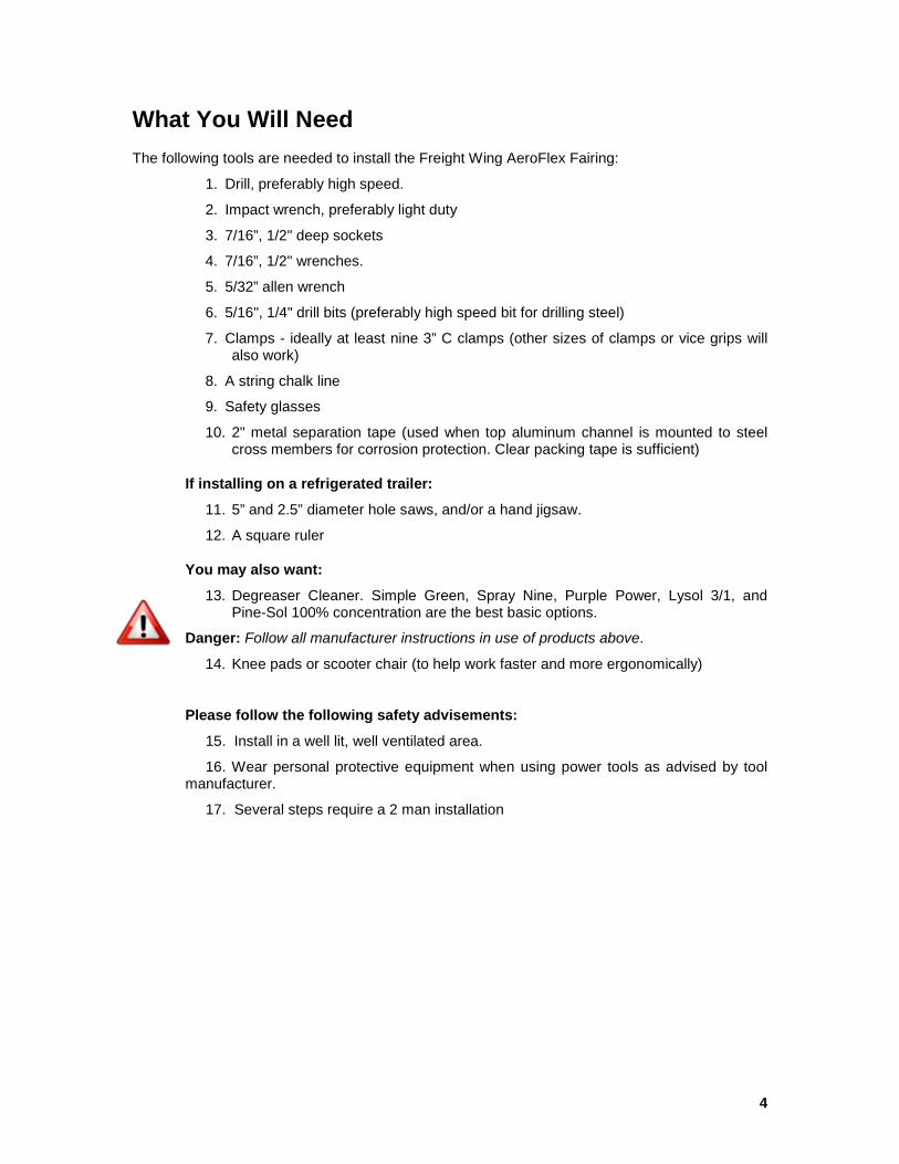
What You Will Need The following tools are needed to install the Freight Wing AeroFlex Fairing:
1. Drill, preferably high speed.
2. Impact wrench, preferably light duty
3. 7/16”, 1/2" deep sockets
4. 7/16”, 1/2" wrenches.
5. 5/32” allen wrench
6. 5/16", 1/4" drill bits (preferably high speed bit for drilling steel)
7. Clamps - ideally at least nine 3” C clamps (other sizes of clamps or vice grips will also work)
8. A string chalk line
9. Safety glasses
10. 2" metal separation tape (used when top aluminum channel is mounted to steel cross members for corrosion protection. Clear packing tape is sufficient)
If installing on a refrigerated trailer:
11. 5” and 2.5” diameter hole saws, and/or a hand jigsaw.
12. A square ruler
You may also want:
13. Degreaser Cleaner. Simple Green, Spray Nine, Purple Power, Lysol 3/1, and Pine-Sol 100% concentration are the best basic options.
Danger: Follow all manufacturer instructions in use of products above.
14. Knee pads or scooter chair (to help work faster and more ergonomically)
Please follow the following safety advisements:
15. Install in a well lit, well ventilated area.
16. Wear personal protective equipment when using power tools as advised by tool manufacturer.
17. Several steps require a 2 man installation

5
Parts and Fastener Lists
Freight Wing Part Number Component Description Qty/Unit
Panel-RR-2012 Panel, Plastic Right Rear (RR) .165 DMP 1
Panel-LR-2012 Panel, Plastic Left Rear (LR) .165 DMP 1
Panel-RM-2012 Panel, Plastic Right Middle (RM) .165 DMP 1
Panel-LM-2012 Panel, Plastic Left Middle (LM) .165 DMP 1
Panel-RF-2012 Panel, Plastic Right Front (RF) .165 DMP 1
Panel-LF-2012 Panel, Plastic Left Front (LF) .165 DMP 1
68-50142-00 L-Channel 6
68-50141-00 Backing Strip, Aluminum 1/8 6
68-50182-00 Support Rods (5/16) 16
68-50140-00 Saddle Bracket (5/16) 32
68-50135-00 Aluminum Square Washer 24
6
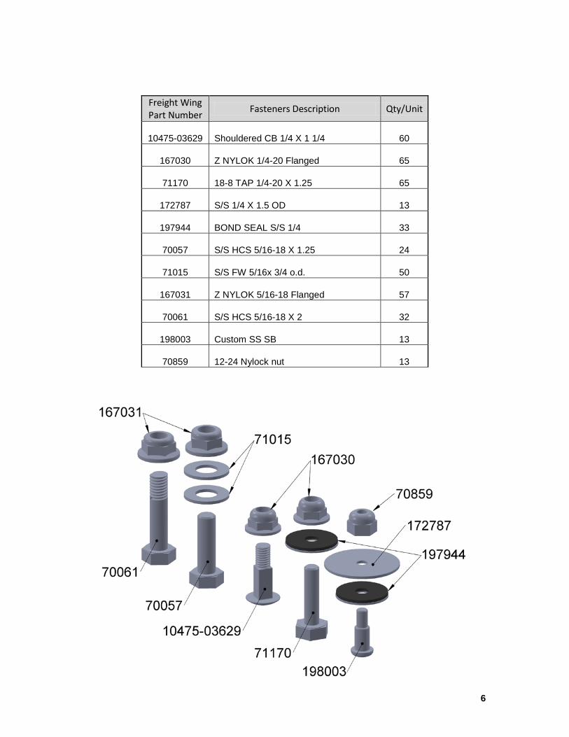
Freight Wing Part Number Fasteners Description Qty/Unit
10475-03629 Shouldered CB 1/4 X 1 1/4 60
167030 Z NYLOK 1/4-20 Flanged 65
71170 18-8 TAP 1/4-20 X 1.25 65
172787 S/S 1/4 X 1.5 OD 13
197944 BOND SEAL S/S 1/4 33
70057 S/S HCS 5/16-18 X 1.25 24
71015 S/S FW 5/16x 3/4 o.d. 50
167031 Z NYLOK 5/16-18 Flanged 57
70061 S/S HCS 5/16-18 X 2 32
198003 Custom SS SB 13
70859 12-24 Nylock nut 13

7
Installation Instructions Step 1: Assembly and Preparation
1a. Gather a support rod (68-50182-00), two saddle mounts (68-50182-00), two 2” 5/16" bolts (70061), and two 5/16” nylon insert lock nuts (37521). Slide the support rod into the saddle as shown below. Note that the saddle extends away from the body of the rod. Insert 5/16" bolt, and firmly tighten the 5/16" nylon lock nut. Repeat for opposite end of rod.
1b. Repeat the process for all 16 rods in each unit.
1c. When mounting the faring on trailers with steel cross members, place metal separation “barrier” tape on all of the long aluminum panel mounting L channels to separate the metals and prevent corrosion. This step is not necessary when mounting on trailers with aluminum cross members. Standard two inch wide clear packing tape (polypropylene tape) is effective as barrier tape and is perfectly sized. Apply the barrier tape across the top of the L channel so it is flush with the outer edge, and use a razor to cut the tape flush with the ends.
8
Step 2: Determine the Starting Rear Position of the AeroFlex Fairing
Properly positioning the AeroFlex fairing on the trailer is important for aerodynamic effectiveness and unobstructed operation of sliding tandems. Because trailers have different axle and slider configurations, the position of the fairing can vary. In general, the rearward edge of the fairing determines its overall position. The rearward edge should be as close to the tires as possible, but must leave enough room for sliding tandems to move into their most forward position with at least 3” of clearance to the tires. At the rearward edge, the fairing is flush with the trailer wall. The fairing is then mounted in a straight line and at an angle, so that the forward tip is just inside (1-2 inches) the landing gear legs or any obstructions created by the landing gear (wing plates, leg supports, etc).
Caution: Improper fairing positioning could interfere in proper operation of the trailer.
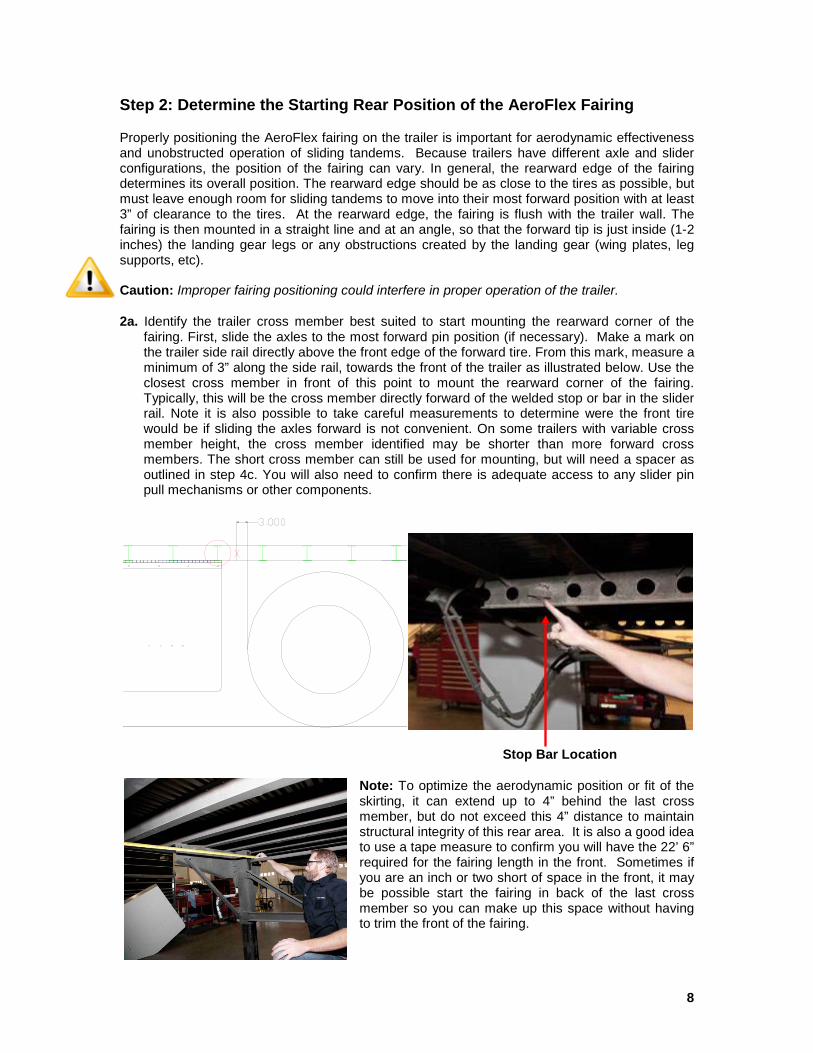
2a. Identify the trailer cross member best suited to start mounting the rearward corner of the fairing. First, slide the axles to the most forward pin position (if necessary). Make a mark on the trailer side rail directly above the front edge of the forward tire. From this mark, measure a minimum of 3” along the side rail, towards the front of the trailer as illustrated below. Use the closest cross member in front of this point to mount the rearward corner of the fairing. Typically, this will be the cross member directly forward of the welded stop or bar in the slider rail. Note it is also possible to take careful measurements to determine were the front tire would be if sliding the axles forward is not convenient. On some trailers with variable cross member height, the cross member identified may be shorter than more forward cross members. The short cross member can still be used for mounting, but will need a spacer as outlined in step 4c. You will also need to confirm there is adequate access to any slider pin pull mechanisms or other components.
Stop Bar Location
Note: To optimize the aerodynamic position or fit of the skirting, it can extend up to 4” behind the last cross member, but do not exceed this 4” distance to maintain structural integrity of this rear area. It is also a good idea to use a tape measure to confirm you will have the 22’ 6” required for the fairing length in the front. Sometimes if you are an inch or two short of space in the front, it may be possible start the fairing in back of the last cross member so you can make up this space without having to trim the front of the fairing.
9
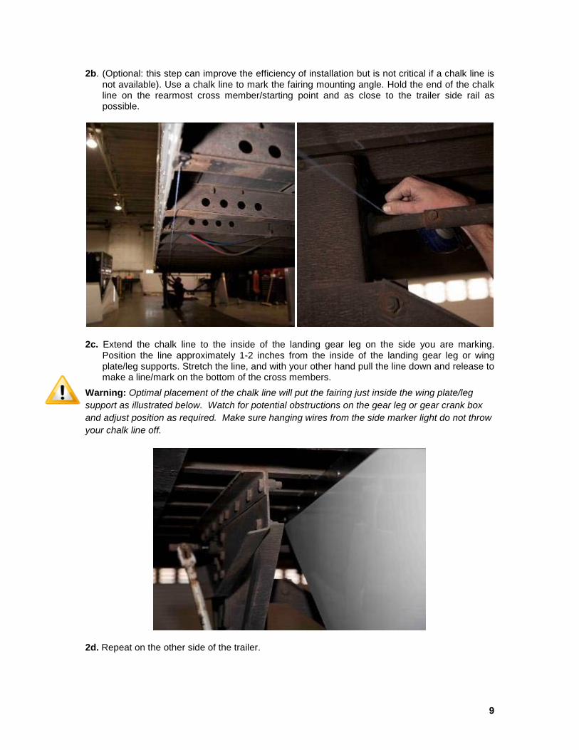
2b. (Optional: this step can improve the efficiency of installation but is not critical if a chalk line is not available). Use a chalk line to mark the fairing mounting angle. Hold the end of the chalk line on the rearmost cross member/starting point and as close to the trailer side rail as possible.
2c. Extend the chalk line to the inside of the landing gear leg on the side you are marking. Position the line approximately 1-2 inches from the inside of the landing gear leg or wing plate/leg supports. Stretch the line, and with your other hand pull the line down and release to make a line/mark on the bottom of the cross members.
Warning: Optimal placement of the chalk line will put the fairing just inside the wing plate/leg support as illustrated below. Watch for potential obstructions on the gear leg or gear crank box and adjust position as required. Make sure hanging wires from the side marker light do not throw your chalk line off.
2d. Repeat on the other side of the trailer.
10
Step 3: Clamp the Panels to the Trailer
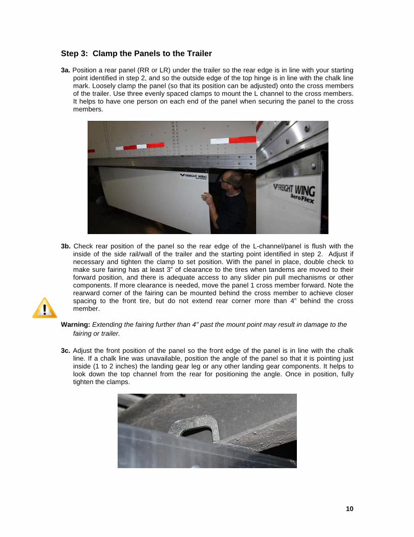
3a. Position a rear panel (RR or LR) under the trailer so the rear edge is in line with your starting point identified in step 2, and so the outside edge of the top hinge is in line with the chalk line mark. Loosely clamp the panel (so that its position can be adjusted) onto the cross members of the trailer. Use three evenly spaced clamps to mount the L channel to the cross members. It helps to have one person on each end of the panel when securing the panel to the cross members.
3b. Check rear position of the panel so the rear edge of the L-channel/panel is flush with the inside of the side rail/wall of the trailer and the starting point identified in step 2. Adjust if necessary and tighten the clamp to set position. With the panel in place, double check to make sure fairing has at least 3” of clearance to the tires when tandems are moved to their forward position, and there is adequate access to any slider pin pull mechanisms or other components. If more clearance is needed, move the panel 1 cross member forward. Note the rearward corner of the fairing can be mounted behind the cross member to achieve closer spacing to the front tire, but do not extend rear corner more than 4” behind the cross member.
Warning: Extending the fairing further than 4" past the mount point may result in damage to the fairing or trailer.
3c. Adjust the front position of the panel so the front edge of the panel is in line with the chalk line. If a chalk line was unavailable, position the angle of the panel so that it is pointing just inside (1 to 2 inches) the landing gear leg or any other landing gear components. It helps to look down the top channel from the rear for positioning the angle. Once in position, fully tighten the clamps.
11
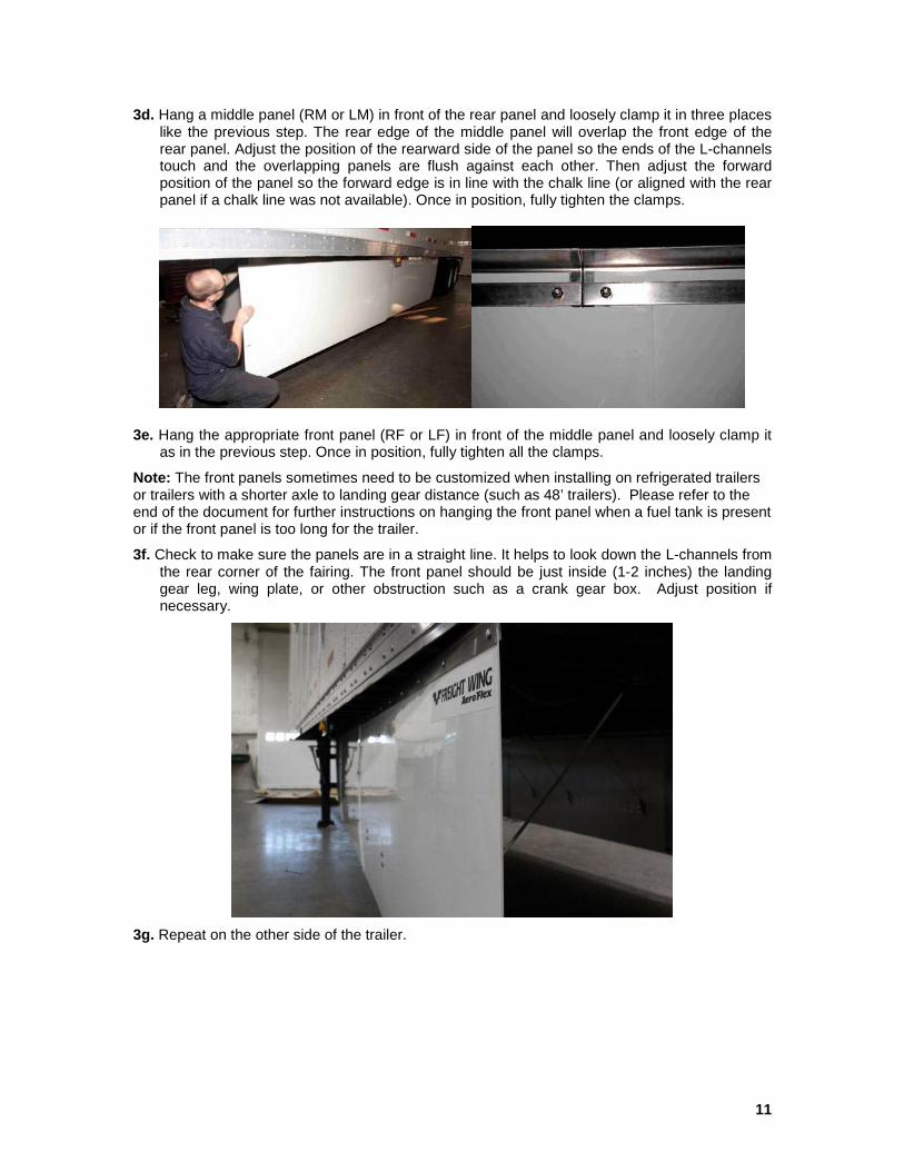
3d. Hang a middle panel (RM or LM) in front of the rear panel and loosely clamp it in three places like the previous step. The rear edge of the middle panel will overlap the front edge of the rear panel. Adjust the position of the rearward side of the panel so the ends of the L-channels touch and the overlapping panels are flush against each other. Then adjust the forward position of the panel so the forward edge is in line with the chalk line (or aligned with the rear panel if a chalk line was not available). Once in position, fully tighten the clamps.
3e. Hang the appropriate front panel (RF or LF) in front of the middle panel and loosely clamp it as in the previous step. Once in position, fully tighten all the clamps.
Note: The front panels sometimes need to be customized when installing on refrigerated trailers or trailers with a shorter axle to landing gear distance (such as 48’ trailers). Please refer to the end of the document for further instructions on hanging the front panel when a fuel tank is present or if the front panel is too long for the trailer.
3f. Check to make sure the panels are in a straight line. It helps to look down the L-channels from the rear corner of the fairing. The front panel should be just inside (1-2 inches) the landing gear leg, wing plate, or other obstruction such as a crank gear box. Adjust position if necessary.
3g. Repeat on the other side of the trailer.
12
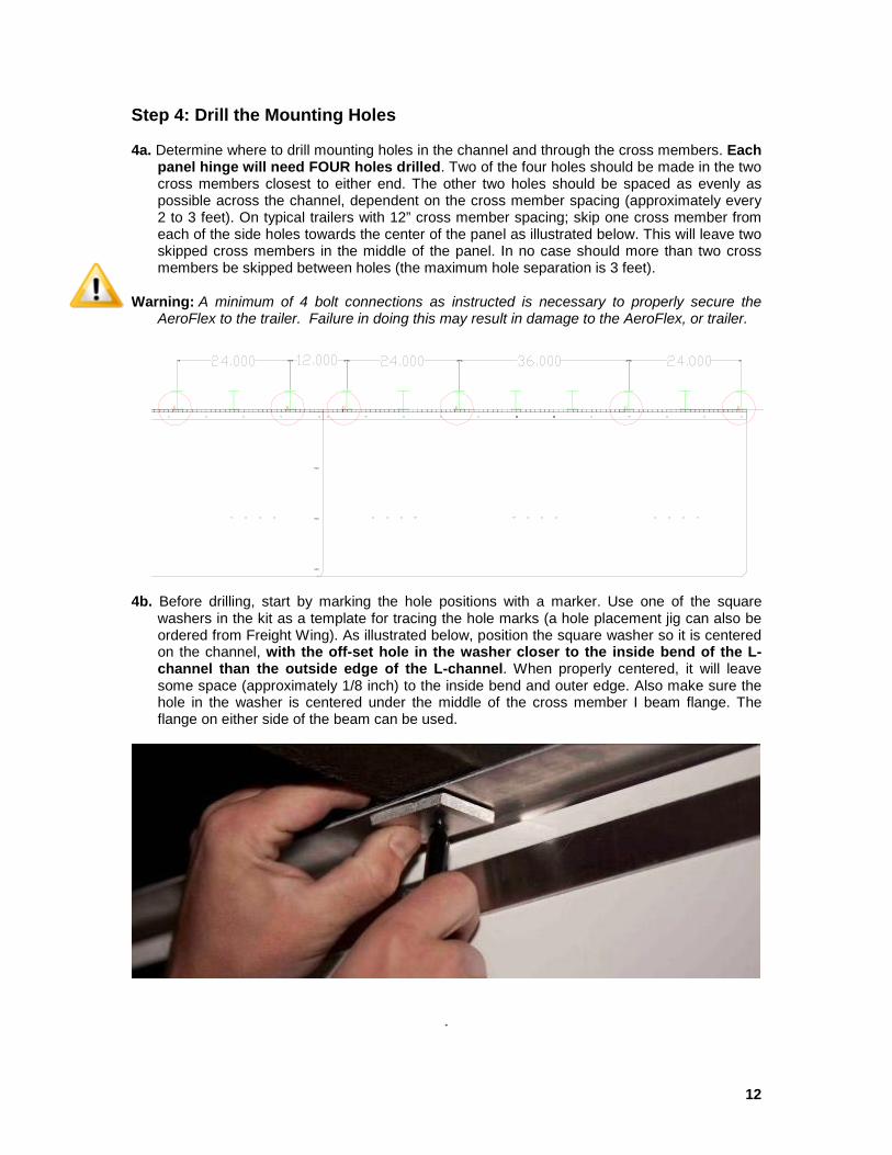
Step 4: Drill the Mounting Holes 4a. Determine where to drill mounting holes in the channel and through the cross members. Each
panel hinge will need FOUR holes drilled. Two of the four holes should be made in the two cross members closest to either end. The other two holes should be spaced as evenly as possible across the channel, dependent on the cross member spacing (approximately every 2 to 3 feet). On typical trailers with 12” cross member spacing; skip one cross member from each of the side holes towards the center of the panel as illustrated below. This will leave two skipped cross members in the middle of the panel. In no case should more than two cross members be skipped between holes (the maximum hole separation is 3 feet).
Warning: A minimum of 4 bolt connections as instructed is necessary to properly secure the AeroFlex to the trailer. Failure in doing this may result in damage to the AeroFlex, or trailer.
4b. Before drilling, start by marking the hole positions with a marker. Use one of the square
washers in the kit as a template for tracing the hole marks (a hole placement jig can also be ordered from Freight Wing). As illustrated below, position the square washer so it is centered on the channel, with the off-set hole in the washer closer to the inside bend of the L-channel than the outside edge of the L-channel. When properly centered, it will leave some space (approximately 1/8 inch) to the inside bend and outer edge. Also make sure the hole in the washer is centered under the middle of the cross member I beam flange. The flange on either side of the beam can be used.
.
13
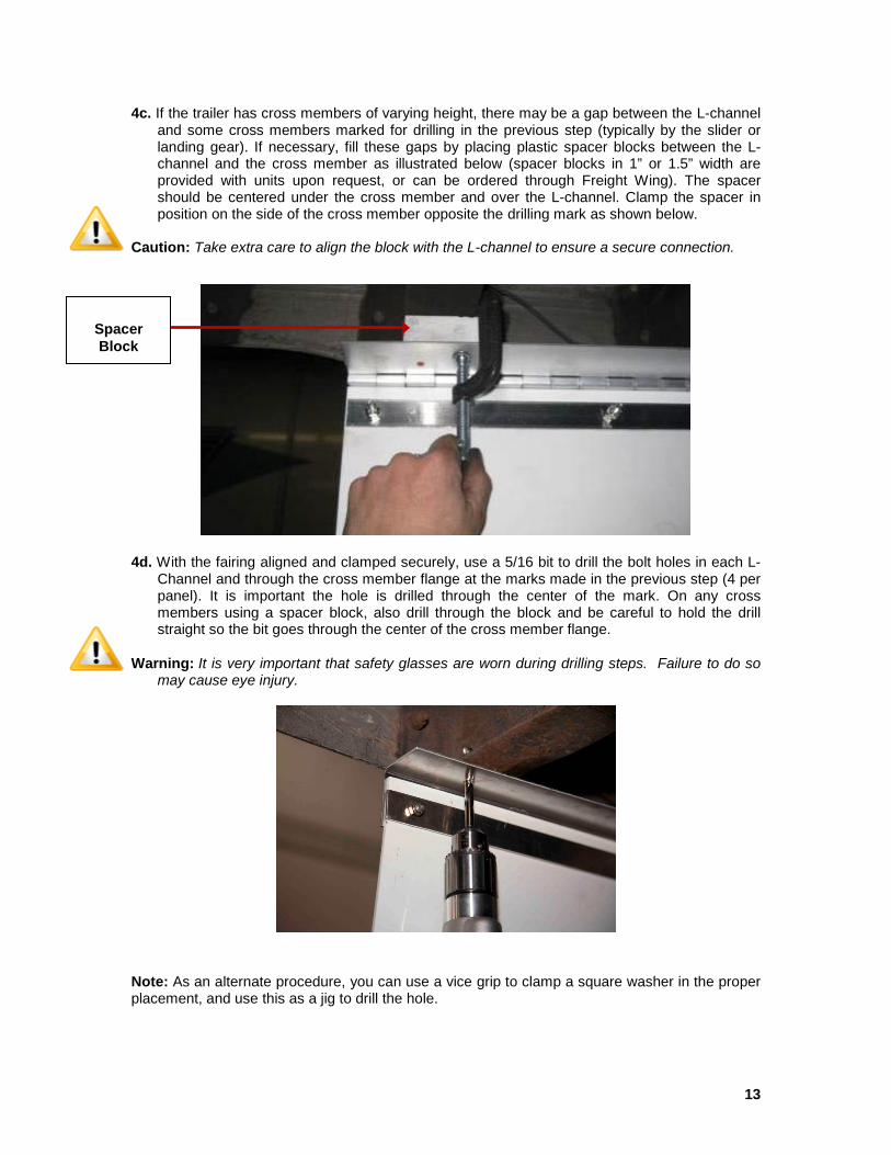
4c. If the trailer has cross members of varying height, there may be a gap between the L-channel and some cross members marked for drilling in the previous step (typically by the slider or landing gear). If necessary, fill these gaps by placing plastic spacer blocks between the L-channel and the cross member as illustrated below (spacer blocks in 1” or 1.5” width are provided with units upon request, or can be ordered through Freight Wing). The spacer should be centered under the cross member and over the L-channel. Clamp the spacer in position on the side of the cross member opposite the drilling mark as shown below.
Caution: Take extra care to align the block with the L-channel to ensure a secure connection.
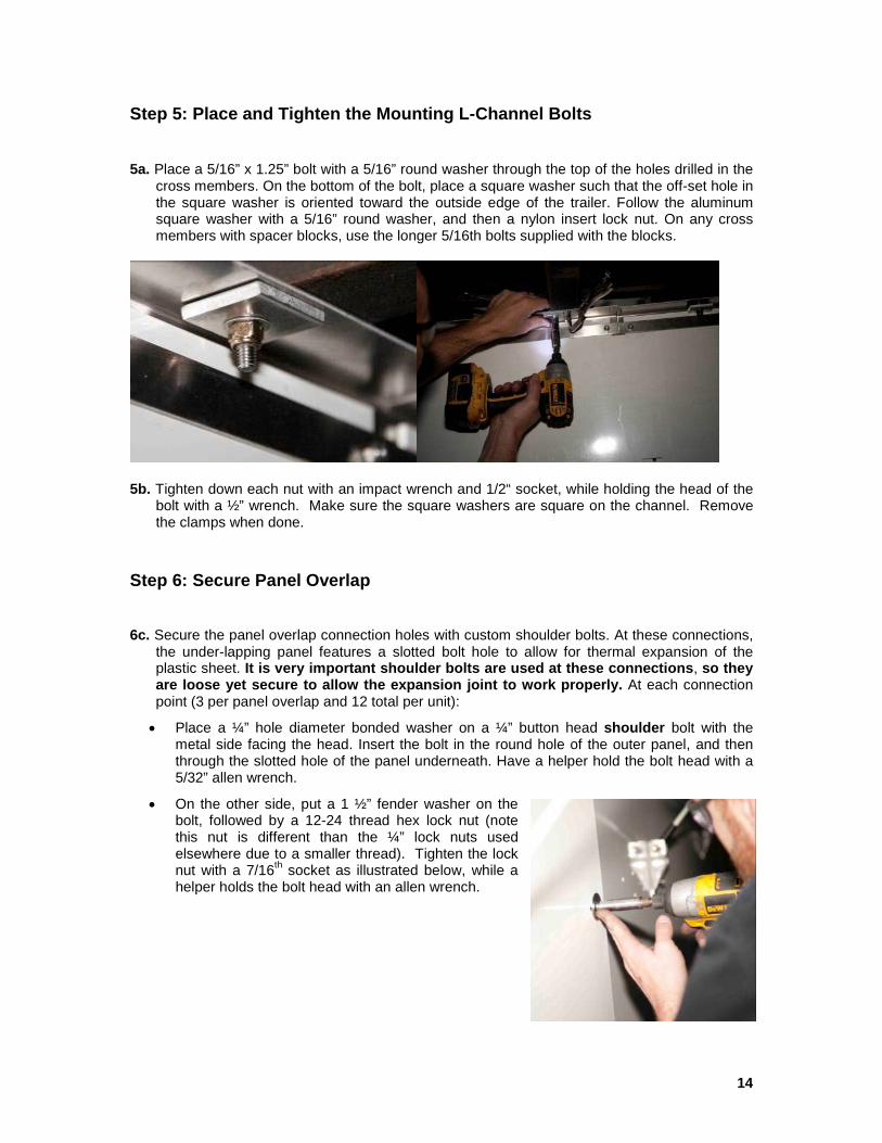
4d. With the fairing aligned and clamped securely, use a 5/16 bit to drill the bolt holes in each L-Channel and through the cross member flange at the marks made in the previous step (4 per panel). It is important the hole is drilled through the center of the mark. On any cross members using a spacer block, also drill through the block and be careful to hold the drill straight so the bit goes through the center of the cross member flange.
Warning: It is very important that safety glasses are worn during drilling steps. Failure to do so may cause eye injury.
Note: As an alternate procedure, you can use a vice grip to clamp a square washer in the proper placement, and use this as a jig to drill the hole.
Spacer Block
14
Step 5: Place and Tighten the Mounting L-Channel Bolts
5a. Place a 5/16” x 1.25” bolt with a 5/16” round washer through the top of the holes drilled in the cross members. On the bottom of the bolt, place a square washer such that the off-set hole in the square washer is oriented toward the outside edge of the trailer. Follow the aluminum square washer with a 5/16” round washer, and then a nylon insert lock nut. On any cross members with spacer blocks, use the longer 5/16th bolts supplied with the blocks.
5b. Tighten down each nut with an impact wrench and 1/2“ socket, while holding the head of the bolt with a ½” wrench. Make sure the square washers are square on the channel. Remove the clamps when done.
Step 6: Secure Panel Overlap 6c. Secure the panel overlap connection holes with custom shoulder bolts. At these connections,
the under-lapping panel features a slotted bolt hole to allow for thermal expansion of the plastic sheet. It is very important shoulder bolts are used at these connections, so they are loose yet secure to allow the expansion joint to work properly. At each connection point (3 per panel overlap and 12 total per unit):
• Place a ¼” hole diameter bonded washer on a ¼” button head shoulder bolt with the metal side facing the head. Insert the bolt in the round hole of the outer panel, and then through the slotted hole of the panel underneath. Have a helper hold the bolt head with a 5/32” allen wrench.
• On the other side, put a 1 ½” fender washer on the bolt, followed by a 12-24 thread hex lock nut (note this nut is different than the ¼” lock nuts used elsewhere due to a smaller thread). Tighten the lock nut with a 7/16th socket as illustrated below, while a helper holds the bolt head with an allen wrench.

15
Step 7: Install the Support Rods
The assembly of the support rods is outlined in step 1. The assembly should be completed on all 16 rods before proceeding with this step. Each support rod will be bolted to the lower section of a panel and to a cross member. The saddle mounts are exactly the same on both ends.
7a. Create a chalk line on the cross-members that is 18" from the top/inside edge of the plastic panel, so that it is parallel to the fairing, and approximately the same length. Measure the 18” and make a mark on two cross members, near the front and rear of the fairing. Then pull the chalk line between these marks. This will be the alignment point of the front edge of the saddle mount on the cross-member. Repeat on both sides. Note this step can also be performed when making the initial chalk line during step 2b, just use a slightly larger measurement of 18 1/4” from the first line.
7b. Starting at either end of the fairing, locate an eight hole rod mounting pattern in the panel (two rows of four holes). Then identify the cross member that is most directly above the middle of the hole pattern. Hold a rod in position so that the bolt holes in the aluminum saddle mate with a pair of holes in the panel. Select the holes in the panel that best allow the rod to align straight with the cross member identified previously (as illustrated below). Note the assembled rod can be positioned on either side of the cross member to achieve the best alignment possible. Attach the bottom saddle mount to the panel first. You will need two 1.25" long 1/4" bolts, and two 1/4" bonded washers, and two 1/4" nylon insert lock nuts to complete this task. Place the bonded washers on the bolts first, and then pass them through the panel holes from the outside of the trailer, and then through the saddle holes. Secure the bolts with 1/4" nylon insert lock nuts, and fully tighten. Note it easiest to accomplish this step with a helper on the outside of the fairing inserting bolts, and holding bolt heads during tightening.
16
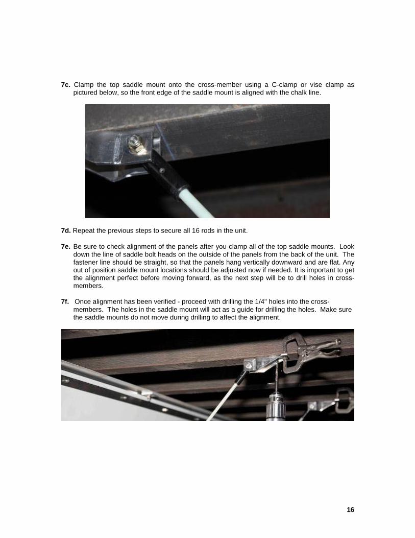
7c. Clamp the top saddle mount onto the cross-member using a C-clamp or vise clamp as pictured below, so the front edge of the saddle mount is aligned with the chalk line.
7d. Repeat the previous steps to secure all 16 rods in the unit.
7e. Be sure to check alignment of the panels after you clamp all of the top saddle mounts. Look down the line of saddle bolt heads on the outside of the panels from the back of the unit. The fastener line should be straight, so that the panels hang vertically downward and are flat. Any out of position saddle mount locations should be adjusted now if needed. It is important to get the alignment perfect before moving forward, as the next step will be to drill holes in cross-members.
7f. Once alignment has been verified - proceed with drilling the 1/4" holes into the cross-members. The holes in the saddle mount will act as a guide for drilling the holes. Make sure the saddle mounts do not move during drilling to affect the alignment.
17
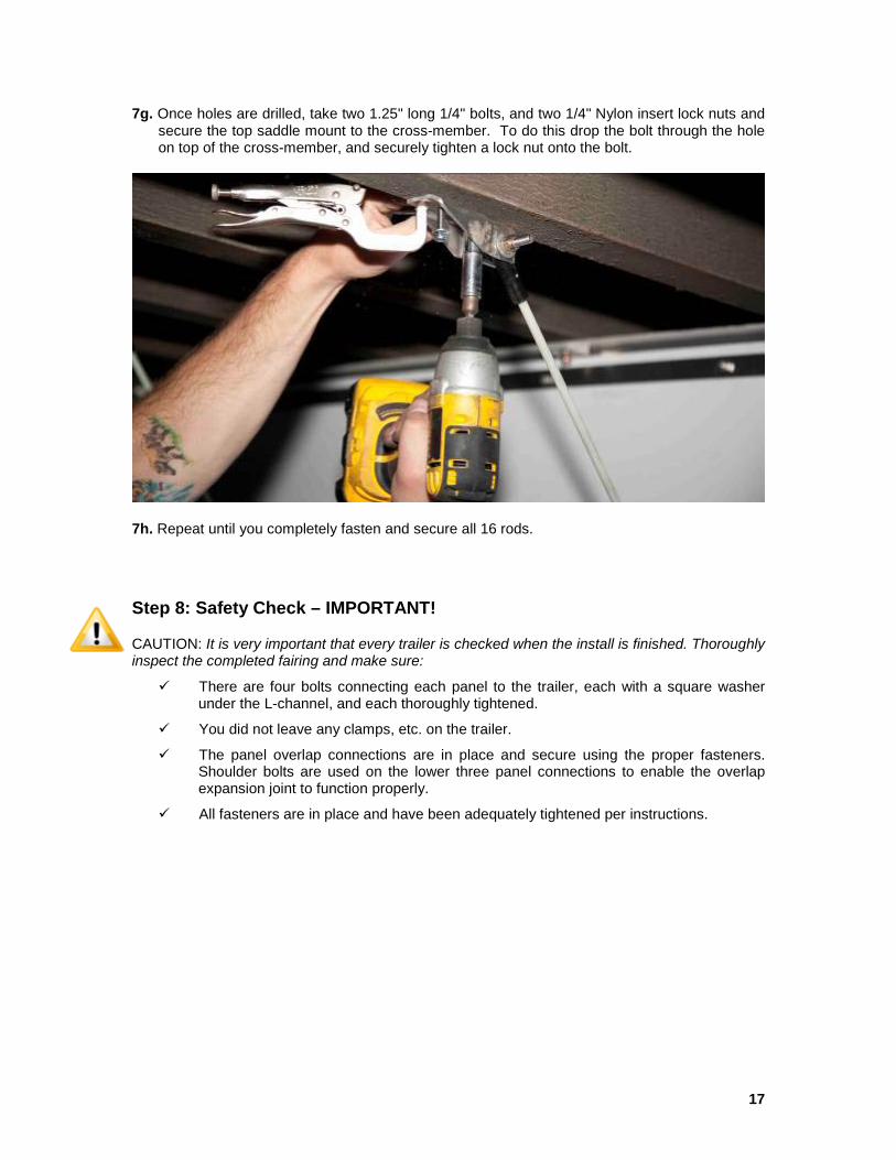
7g. Once holes are drilled, take two 1.25" long 1/4" bolts, and two 1/4" Nylon insert lock nuts and secure the top saddle mount to the cross-member. To do this drop the bolt through the hole on top of the cross-member, and securely tighten a lock nut onto the bolt.
7h. Repeat until you completely fasten and secure all 16 rods. Step 8: Safety Check – IMPORTANT!
CAUTION: It is very important that every trailer is checked when the install is finished. Thoroughly inspect the completed fairing and make sure:
There are four bolts connecting each panel to the trailer, each with a square washer under the L-channel, and each thoroughly tightened.
You did not leave any clamps, etc. on the trailer.
The panel overlap connections are in place and secure using the proper fasteners. Shoulder bolts are used on the lower three panel connections to enable the overlap expansion joint to function properly.
All fasteners are in place and have been adequately tightened per instructions.

18
Customizing Fairing Length
The length of the AeroFlex fairing can easily be reduced to accommodate trailers with a shorter wheel to landing gear distance (such as 48’ trailers). The best way to reduce the fairings length by up to 3’ is to cut the triangular tip of the front panels off with a hand jig saw as described below. In the unusual case of needing to reduce length by more than 3’, please contact Freight Wing for customized instructions on your specific trailer.
A. Clamp rear and middle panels in position as described in step 4. Hold the front panel ahead of the middle panel with the L-channels touching, and against the outside of the landing gear as shown below. Mark the panel where it would intersect the landing gear leg or other components if the panel were properly positioned just inside the landing gear.
B. Remove the panel, and use a square to mark a vertical cut line (square to the hinge) 1 inch further back from the mark made previously (to insure adequate clearance). Make sure the line does not go through a fastener on the L-channel (if it does, move it back another inch). Use a hand jig saw to cut the panel and hinge off at the line. Position the cut panel in front of and in line with the middle panel as described in step 3 to make sure it fits well. Complete the same process for the other side of the fairing.
19
Refrigerated Trailer Installation
The AeroFlex fairing is easily customized during installation to enable access to refrigerated trailer fuel tanks. The standard refrigerated trailer installation method outlined below cuts small holes the front panel to access the nozzle and view the fuel level gauge and is approved by CARB as an accepted modification. This method requires the fuel tank to be mounted inside the landing gear, so that the fairing can pass in front of the tank when properly positioned. In some cases it may require moving the fuel tank so that the fairing can pass in front of the tank. Usually, this can be accomplished by removing fuel tank bracket bolts, sliding the tank back on the cross members, and reconnecting the bracket at the needed location. The rear and middle panels should be clamped in position on the tank side of the trailer as outlined in steps 3a-3d before proceeding with the instructions below.
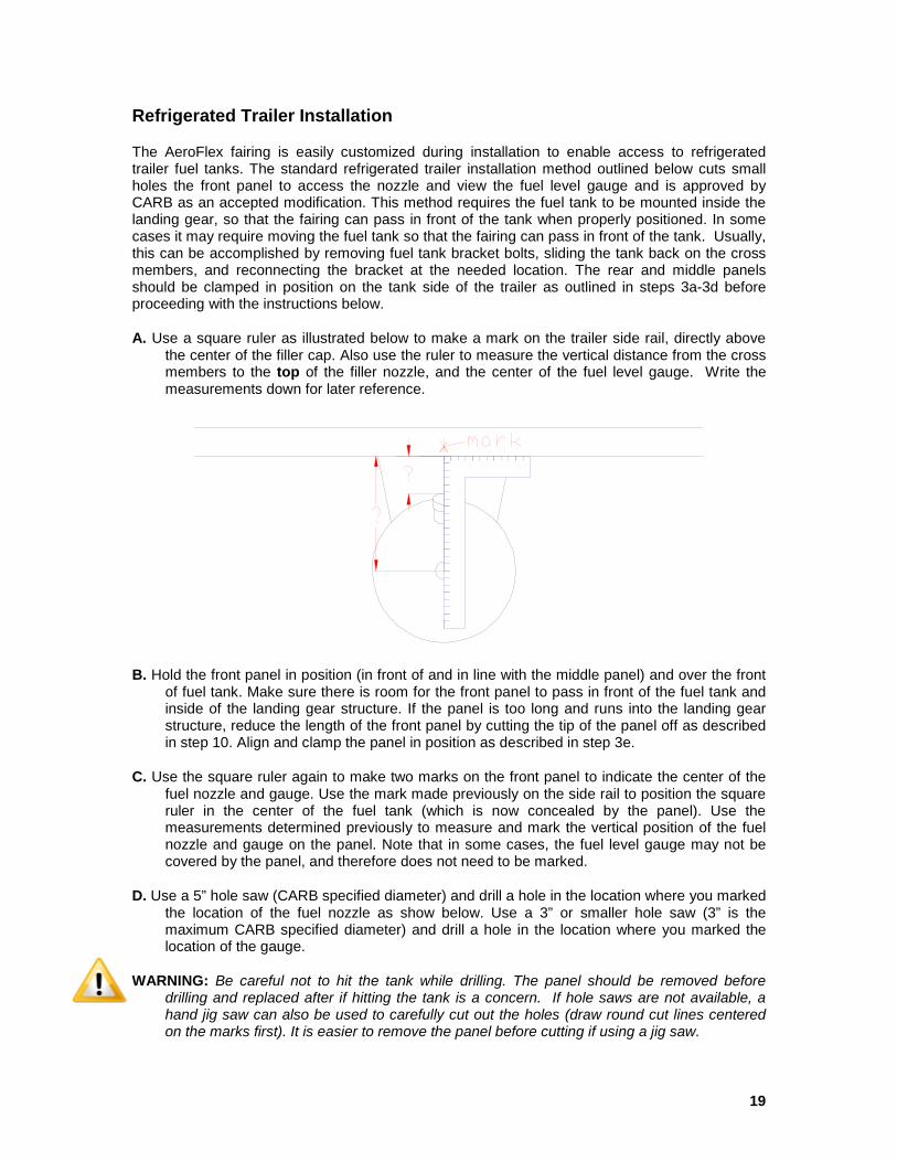
A. Use a square ruler as illustrated below to make a mark on the trailer side rail, directly above the center of the filler cap. Also use the ruler to measure the vertical distance from the cross members to the top of the filler nozzle, and the center of the fuel level gauge. Write the measurements down for later reference.
B. Hold the front panel in position (in front of and in line with the middle panel) and over the front of fuel tank. Make sure there is room for the front panel to pass in front of the fuel tank and inside of the landing gear structure. If the panel is too long and runs into the landing gear structure, reduce the length of the front panel by cutting the tip of the panel off as described in step 10. Align and clamp the panel in position as described in step 3e.
C. Use the square ruler again to make two marks on the front panel to indicate the center of the fuel nozzle and gauge. Use the mark made previously on the side rail to position the square ruler in the center of the fuel tank (which is now concealed by the panel). Use the measurements determined previously to measure and mark the vertical position of the fuel nozzle and gauge on the panel. Note that in some cases, the fuel level gauge may not be covered by the panel, and therefore does not need to be marked.
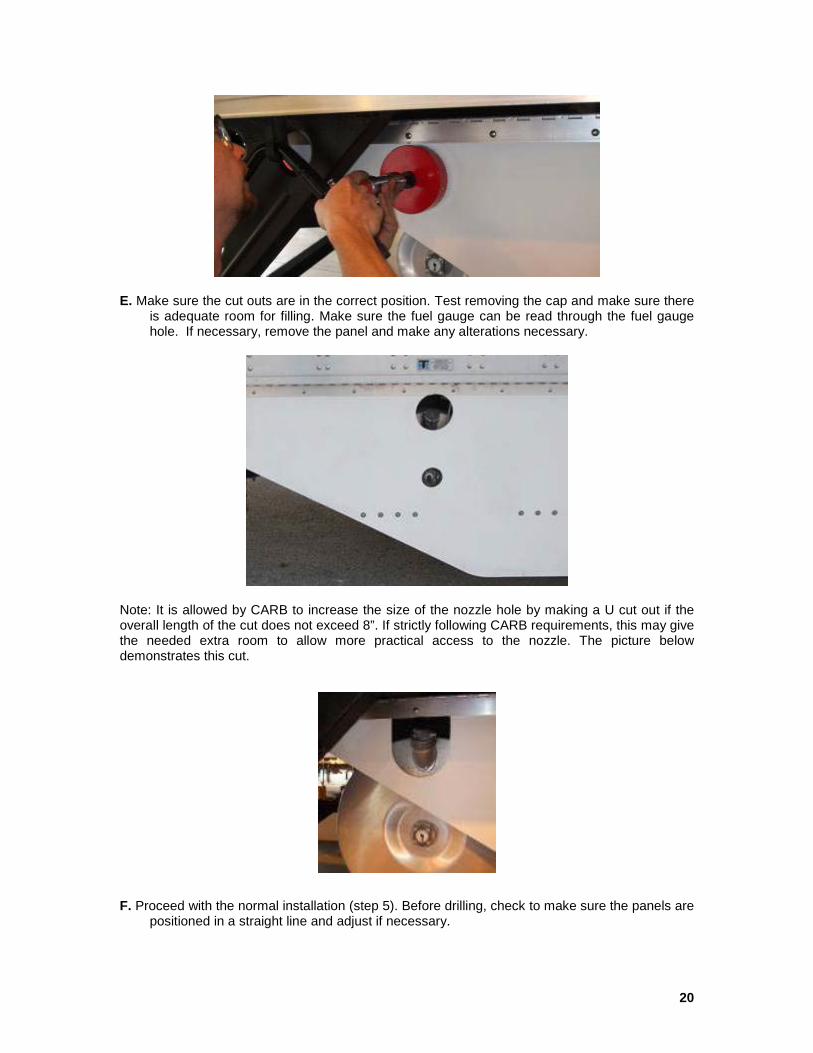
D. Use a 5” hole saw (CARB specified diameter) and drill a hole in the location where you marked the location of the fuel nozzle as show below. Use a 3” or smaller hole saw (3” is the maximum CARB specified diameter) and drill a hole in the location where you marked the location of the gauge.
WARNING: Be careful not to hit the tank while drilling. The panel should be removed before drilling and replaced after if hitting the tank is a concern. If hole saws are not available, a hand jig saw can also be used to carefully cut out the holes (draw round cut lines centered on the marks first). It is easier to remove the panel before cutting if using a jig saw.
20
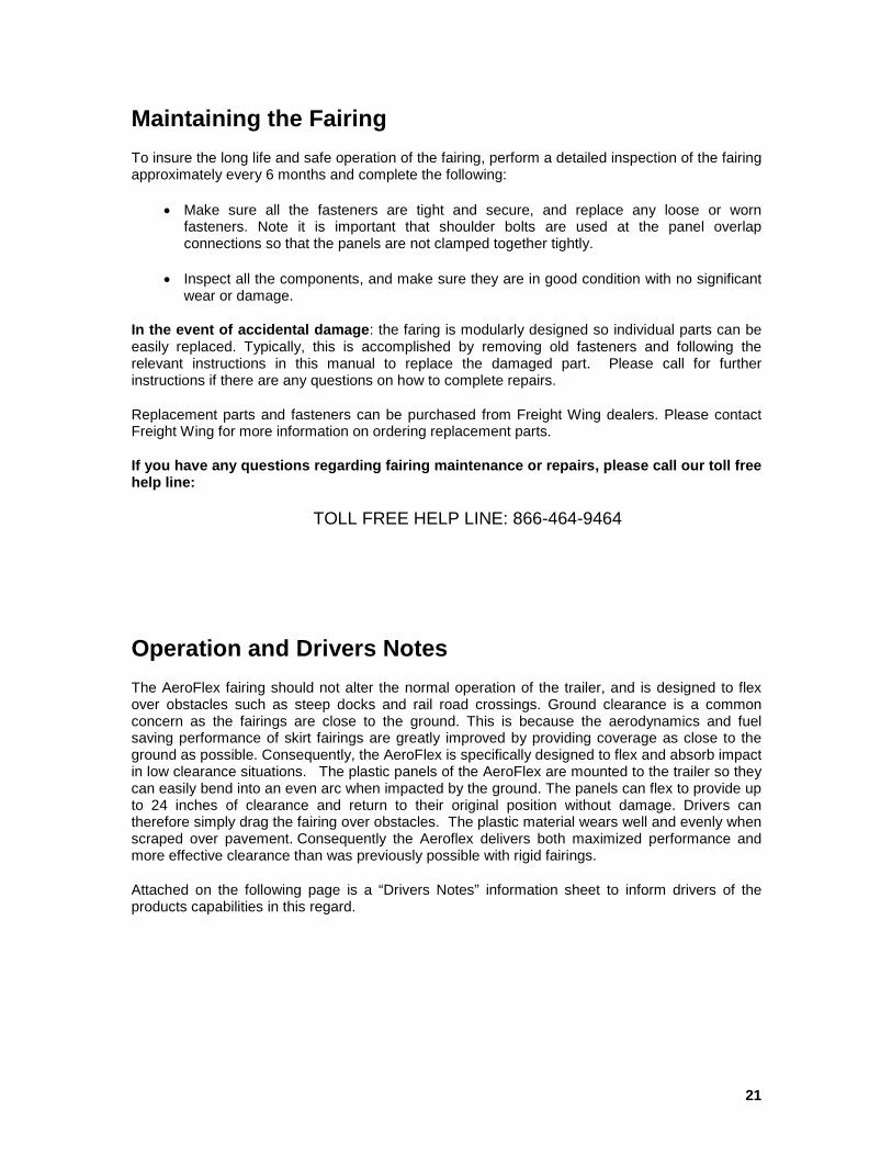
E. Make sure the cut outs are in the correct position. Test removing the cap and make sure there is adequate room for filling. Make sure the fuel gauge can be read through the fuel gauge hole. If necessary, remove the panel and make any alterations necessary.
Note: It is allowed by CARB to increase the size of the nozzle hole by making a U cut out if the overall length of the cut does not exceed 8”. If strictly following CARB requirements, this may give the needed extra room to allow more practical access to the nozzle. The picture below demonstrates this cut.
F. Proceed with the normal installation (step 5). Before drilling, check to make sure the panels are positioned in a straight line and adjust if necessary.
21
Maintaining the Fairing
To insure the long life and safe operation of the fairing, perform a detailed inspection of the fairing approximately every 6 months and complete the following:
• Make sure all the fasteners are tight and secure, and replace any loose or worn fasteners. Note it is important that shoulder bolts are used at the panel overlap connections so that the panels are not clamped together tightly.
• Inspect all the components, and make sure they are in good condition with no significant wear or damage.
In the event of accidental damage: the faring is modularly designed so individual parts can be easily replaced. Typically, this is accomplished by removing old fasteners and following the relevant instructions in this manual to replace the damaged part. Please call for further instructions if there are any questions on how to complete repairs.
Replacement parts and fasteners can be purchased from Freight Wing dealers. Please contact Freight Wing for more information on ordering replacement parts.
If you have any questions regarding fairing maintenance or repairs, please call our toll free help line:
TOLL FREE HELP LINE: 866-464-9464
Operation and Drivers Notes The AeroFlex fairing should not alter the normal operation of the trailer, and is designed to flex over obstacles such as steep docks and rail road crossings. Ground clearance is a common concern as the fairings are close to the ground. This is because the aerodynamics and fuel saving performance of skirt fairings are greatly improved by providing coverage as close to the ground as possible. Consequently, the AeroFlex is specifically designed to flex and absorb impact in low clearance situations. The plastic panels of the AeroFlex are mounted to the trailer so they can easily bend into an even arc when impacted by the ground. The panels can flex to provide up to 24 inches of clearance and return to their original position without damage. Drivers can therefore simply drag the fairing over obstacles. The plastic material wears well and evenly when scraped over pavement. Consequently the Aeroflex delivers both maximized performance and more effective clearance than was previously possible with rigid fairings.
Attached on the following page is a “Drivers Notes” information sheet to inform drivers of the products capabilities in this regard.
22
Attention Drivers: Trailer Fairing Implementation
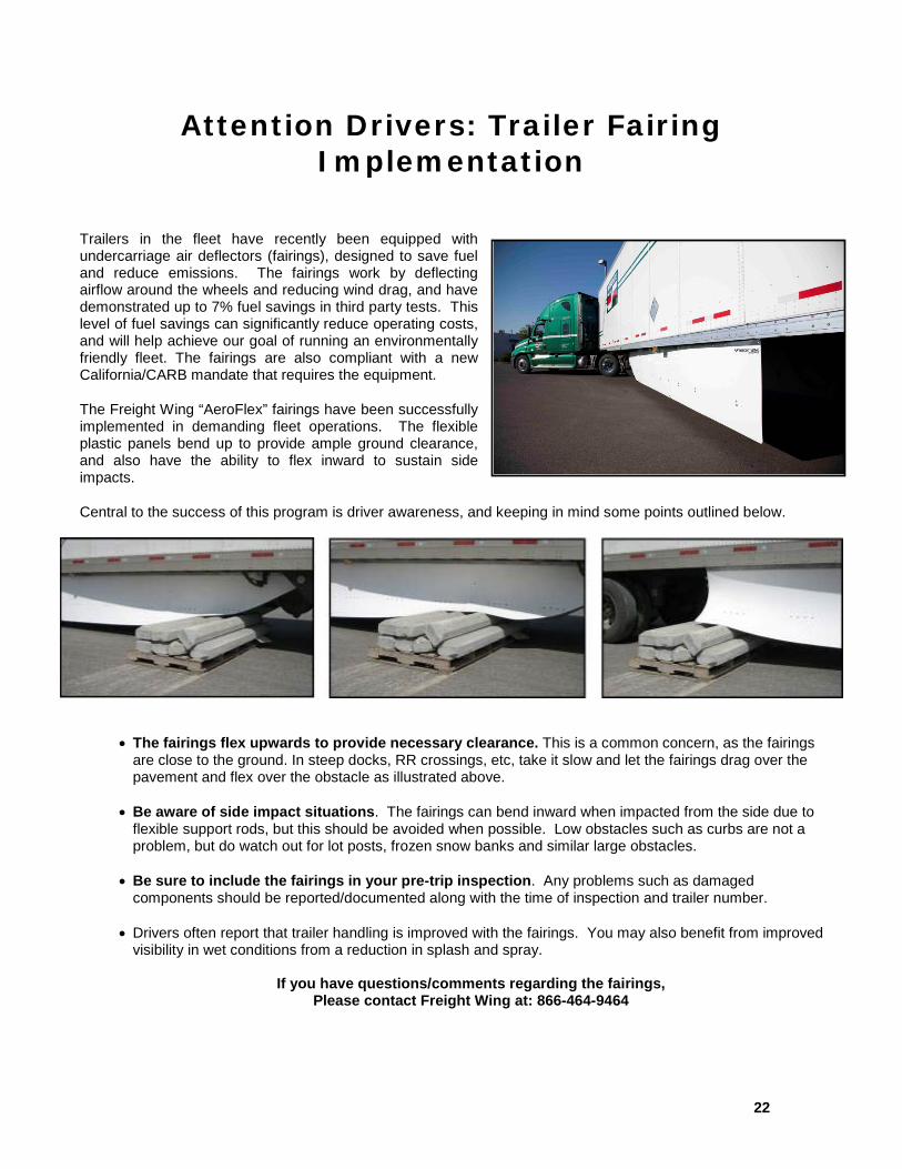
Trailers in the fleet have recently been equipped with undercarriage air deflectors (fairings), designed to save fuel and reduce emissions. The fairings work by deflecting airflow around the wheels and reducing wind drag, and have demonstrated up to 7% fuel savings in third party tests. This level of fuel savings can significantly reduce operating costs, and will help achieve our goal of running an environmentally friendly fleet. The fairings are also compliant with a new California/CARB mandate that requires the equipment.
The Freight Wing “AeroFlex” fairings have been successfully implemented in demanding fleet operations. The flexible plastic panels bend up to provide ample ground clearance, and also have the ability to flex inward to sustain side impacts.
Central to the success of this program is driver awareness, and keeping in mind some points outlined below.
• The fairings flex upwards to provide necessary clearance. This is a common concern, as the fairings
are close to the ground. In steep docks, RR crossings, etc, take it slow and let the fairings drag over the pavement and flex over the obstacle as illustrated above.
• Be aware of side impact situations. The fairings can bend inward when impacted from the side due to flexible support rods, but this should be avoided when possible. Low obstacles such as curbs are not a problem, but do watch out for lot posts, frozen snow banks and similar large obstacles.
• Be sure to include the fairings in your pre-trip inspection. Any problems such as damaged components should be reported/documented along with the time of inspection and trailer number.
• Drivers often report that trailer handling is improved with the fairings. You may also benefit from improved visibility in wet conditions from a reduction in splash and spray.
If you have questions/comments regarding the fairings, Please contact Freight Wing at: 866-464-9464