aerohive planning report - · pdf fileaerohive planning report introduction thank you for...
TRANSCRIPT

●
●
●
●
●
●
●
Aerohive Planning Report
Introduction
Thank you for using the Aerohive Planning Tool. This tool is designed to help scope and plan a WiFi Deployment to
determine the number of APs required to achieve an intended coverage, AP placement and datarates. This tool calculates
the loss in signal strength as it passes through open air and various materials to show predicted coverage.
RF Prediction with Optional Site Survey
An RF prediction is an estimate of WLAN performance and coverage. It uses intelligent algorithms to examine AP behavior
based upon an imported floor plan with assigned building characteristics. The accuracy of an RF prediction is dependent
upon the confidence level with which the building's RF characteristics are assigned, and the accuracy of AP placement. It
is ideal for typical office environments with uniform wall types. In addition RF itself can be unpredictable, due to the
difficulty of characterizing the behavior of RF when interacting with various materials.
Complex environments should be verified with a survey to verify the assumptions used in an RF prediction.
Assumptions
The guidelines in this document are based on the following conditions and assumptions:
Client Data Terminal Transmit (Tx) Power: >=15 dBm.
Client Data Terminal Antenna Gain: >=0 dBi.
The map environment type (e.g. Warehouse, Office) relates to an average density which is quantified as a path
loss exponent value. It estimates how quickly an RF signal attenuates with distance.
The indicated wall path-through loss number (e.g. 12dB for a concrete wall) is the attenuation of an RF signal as
it travels through the wall under a right angle. For any other angle, the loss will be higher.
The EIRP (Effective Isotropic Radiated Power) of an AP's radio is determined by the Tx power setting, the
antenna gain and cable losses. The antenna gain is an average gain obtained through measurements for the
different AP types.
Data rates are based on receive sensitivity numbers obtained through measurements for the different AP types,
and a fade margin which is user configurable.
The data rates for n-type APs assume a channel width of 20 MHz (HT20 data rates).
Note: These assumptions are typical for available 802.11 client Data Terminals and typical cubicle densities.
1. V8
1.0 Building view
Prepared time: 11-29-2012 18:25:08
1

Prepared time: 11-29-2012 18:25:08
2

1.1 FHFL7
There are no APs on FHFL7
1.2 FHDL6
There are no APs on FHDL6
Prepared time: 11-29-2012 18:25:08
3
1.3 FHFL5
There are no APs on FHFL5
1.4 FHFL4
There are no APs on FHFL4
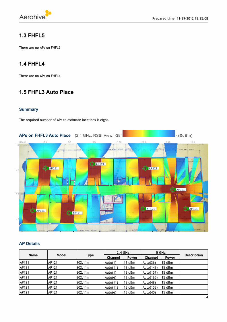
1.5 FHFL3 Auto Place
Summary
The required number of APs to estimate locations is eight.
APs on FHFL3 Auto Place
AP Details
(2.4 GHz, RSSI View: -35 -80dBm)
0 feet 2 5 5 0 7 5 100 125 150 1750
2 5
5 0
7 5
AP121AP121
AP121
AP121
AP121
AP121
AP121
AP121
Name Model Type2.4 GHz 5 GHz
DescriptionChannel Power Channel Power
AP121 AP121 802.11n Auto(1) 18 dBm Auto(36) 15 dBmAP121 AP121 802.11n Auto(11) 18 dBm Auto(149) 15 dBmAP121 AP121 802.11n Auto(1) 18 dBm Auto(157) 15 dBmAP121 AP121 802.11n Auto(6) 18 dBm Auto(165) 15 dBmAP121 AP121 802.11n Auto(11) 18 dBm Auto(48) 15 dBmAP121 AP121 802.11n Auto(11) 18 dBm Auto(153) 15 dBmAP121 AP121 802.11n Auto(6) 18 dBm Auto(40) 15 dBm
Prepared time: 11-29-2012 18:25:08
4

1.6 FHFL2 7+APs
Summary
The required number of APs to estimate locations is seven.
APs on FHFL2 7+APs
AP Details
1.7 FHFL2 6APs
Name Model Type2.4 GHz 5 GHz
DescriptionChannel Power Channel Power
AP121 AP121 802.11n Auto(1) 18 dBm Auto(161) 15 dBm
(2.4 GHz, RSSI View: -35 -80dBm)
0 feet 2 5 5 0 7 5 100 125 150 1750
2 5
5 0
7 5
AP121
AP121
AP121
AP121
AP121
AP121AP121
Name Model Type2.4 GHz 5 GHz
DescriptionChannel Power Channel Power
AP121 AP121 802.11n Auto(6) 18 dBm Auto(44) 15 dBmAP121 AP121 802.11n Auto(11) 18 dBm Auto(153) 15 dBmAP121 AP121 802.11n Auto(1) 18 dBm Auto(40) 15 dBmAP121 AP121 802.11n Auto(11) 18 dBm Auto(36) 15 dBmAP121 AP121 802.11n Auto(11) 18 dBm Auto(149) 15 dBmAP121 AP121 802.11n Auto(6) 18 dBm Auto(157) 15 dBmAP121 AP121 802.11n Auto(1) 18 dBm Auto(48) 15 dBm
Prepared time: 11-29-2012 18:25:08
5
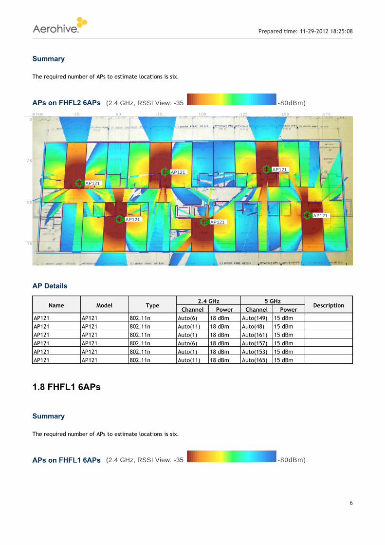
Summary
The required number of APs to estimate locations is six.
APs on FHFL2 6APs
AP Details
1.8 FHFL1 6APs
Summary
The required number of APs to estimate locations is six.
APs on FHFL1 6APs
(2.4 GHz, RSSI View: -35 -80dBm)
0 feet 2 5 5 0 7 5 100 125 150 1750
2 5
5 0
7 5
AP121
AP121AP121AP121
AP121
AP121
Name Model Type2.4 GHz 5 GHz
DescriptionChannel Power Channel Power
AP121 AP121 802.11n Auto(6) 18 dBm Auto(149) 15 dBmAP121 AP121 802.11n Auto(11) 18 dBm Auto(48) 15 dBmAP121 AP121 802.11n Auto(1) 18 dBm Auto(161) 15 dBmAP121 AP121 802.11n Auto(6) 18 dBm Auto(157) 15 dBmAP121 AP121 802.11n Auto(1) 18 dBm Auto(153) 15 dBmAP121 AP121 802.11n Auto(11) 18 dBm Auto(165) 15 dBm
(2.4 GHz, RSSI View: -35 -80dBm)
Prepared time: 11-29-2012 18:25:08
6

AP Details
0 feet 2 5 5 0 7 5 100 125 150 175 2000
2 5
5 0
7 5
AP121
AP121
AP121
AP121AP121
AP121
Name Model Type2.4 GHz 5 GHz
DescriptionChannel Power Channel Power
AP121 AP121 802.11n Auto(6) 18 dBm Auto(40) 15 dBmAP121 AP121 802.11n Auto(11) 18 dBm Auto(44) 15 dBmAP121 AP121 802.11n Auto(11) 18 dBm Auto(48) 15 dBmAP121 AP121 802.11n Auto(6) 18 dBm Auto(153) 15 dBmAP121 AP121 802.11n Auto(1) 18 dBm Auto(36) 15 dBmAP121 AP121 802.11n Auto(1) 18 dBm Auto(157) 15 dBm
Prepared time: 11-29-2012 18:25:08
7