aeronautical design standard - mil-std-188everyspec.com/army/ads-aero-design-std/download... ·...
TRANSCRIPT
FOOT-POUND
ADS-10C-SP 13 March 2000 CAGE Code 18876
AERONAUTICAL DESIGN STANDARD
STANDARD PRACTICE
AIR VEHICLE TECHNICAL DESCRIPTION
AMSC N/A DISTRIBUTION STATEMENT A. Approved for public release, distribution is unlimited.
Downloaded from http://www.everyspec.com
ii
Downloaded from http://www.everyspec.com

iii
Downloaded from http://www.everyspec.com
ADS-10C-SP
CONTENTS TABLE PAGE
1. SCOPE .......................................................................................................................1 1.1 Scope ..................................................................................................................1 2. APPLICABLE DOCUMENTS .................................................................................1 2.1 General ...............................................................................................................1 2.2 Government documents......................................................................................1 2.3 Order of precedence ...........................................................................................2 3. DEFINITIONS...........................................................................................................2 3.1 Acronyms ...........................................................................................................2 4. GENERAL REQUIREMENTS .................................................................................3 4.1 Documentation ...................................................................................................3 4.2 Graphs ................................................................................................................3 4.3 Tables .................................................................................................................3 4.4 Drawings ............................................................................................................3 4.5 Substantiation .....................................................................................................3 5. DETAILED REQUIREMENTS................................................................................4 5.1 Air vehicle dimensional data, Level I ................................................................4 5.1.1 Drawings ............................................................................................................4 5.1.2 Tabulated dimensions and areas.........................................................................5 5.2 Air vehicle dimensional data, Level II ...............................................................6 5.2.1 Drawings ............................................................................................................6 5.2.2 Airfoil drawings .................................................................................................6 5.3 Air vehicle dimensional data, Level III..............................................................7 5.3.1 Basic drawings ...................................................................................................7 5.3.2 Structure drawings..............................................................................................7 5.3.3 Propulsion system drawings...............................................................................8 5.3.4 Equipment drawings...........................................................................................8 5.4 Description of the rotor systems.........................................................................8 5.5 Airfoil section data .............................................................................................12 5.6 Airframe aerodynamic data ................................................................................13 5.7 Rotor structural dynamics data...........................................................................15 5.8 Airframe structural dynamics data .....................................................................16 5.9 Aerodynamic surface data ..................................................................................17 5.10 Control system data ............................................................................................18 5.11 Propulsion and drive system data.......................................................................20 6. NOTES.......................................................................................................................20 6.1 Rotor wake aerodynamic interference................................................................20 6.2 Component aerodynamics ..................................................................................20 6.3 Airfoil Level III data ..........................................................................................21
iv
Downloaded from http://www.everyspec.com
ADS-10C-SP
CONTENTS TABLE PAGE
I Aerodynamic Surfaces .......................................................................................6 II Rotor Data ..........................................................................................................9 III Radial Distribution of Rotor Blade Properties Units .........................................10 IV Rotor System Data..............................................................................................10 V Radial Distribution of Rotor Blade Properties Data...........................................11 VI Aerodynamics of Fuselage Data.........................................................................14 VII Data for Ground Resonance Model....................................................................16 VIII Surface 3-dimensional Force and Moment Data................................................18 IX Control Travel Data............................................................................................19
v
Downloaded from http://www.everyspec.com
ADS-10C-SP
AIR VEHICLE TECHNICAL DESCRIPTION 1. SCOPE 1.1 Scope. This standard practice Aeronautical Design Standard specifies the air vehicle technical data necessary to perform a detailed analysis of the performance, handling qualities, rotor dynamics, airframe dynamics, and acoustics of proposed new development or derivative rotorcraft. It is the purpose of this standard to provide a clear technical description of the proposed air vehicle and its components at a level of detail consistent with the current stage of its design. To this end, the data requirements are divided into topics and the topics are divided into three levels: Level I, Level II, and Level III. Level I (minimum) requires sufficient information to conduct a basic performance and stability and control analysis including the aerodynamic effects of the rotor system and the fuselage. Level II (intermediate) requires all of the data required for Level I plus additional data required for more detailed rotor and fuselage aerodynamics and a basic dynamic analysis of the rotors and the fuselage. Level III (detailed) is intended to allow a very detailed aerodynamic and dynamic analysis. This standard practice Aeronautical Design Standard is a communications tool. It is intended to provide a standard nomenclature and format for providing a technical description of the design. This standard contains a set of requirements designed to be tailored for each contract by the contracting agency. The tailoring process intended for this standard is the deletion of non-applicable requirements 2. APPLICABLE DOCUMENTS 2.1 General. The documents listed in this section are specified in sections 3, 4, and 5 of this standard. This section does not include documents cited in other sections of this standard or recommended for additional information or as examples. While every effort has been made to ensure the completeness of this list, documents users are cautioned that they must meet all specified requirements documents cited in sections 3, 4, and 5 of this standard, whether or not they are listed. 2.2 Government documents. The following Government documents, drawings, and publications form a part of this document to the extent specified herein. Unless otherwise specified, the issues are those cited in the solicitation.
NACA Report 1351 Theory of Self-Excited Mechanical Oscillations of Helicopter Rotors with Hinged Blades
NASA TM-78627 Computer Program to Prepare Airfoil
Characteristics Data for Use in Helicopter Performance Calculation
1
Downloaded from http://www.everyspec.com
ADS-10C-SP
USAATCOM TM 93-A-004 Second Generation Comprehensive Helicopter Analysis System
USAAVRADCOM-TR-80-A-5,6,7 Comprehensive Analytical Model of Rotorcraft
Aerodynamics and Dynamics USAAVRADCOM-TR-80-D-38A Rotorcraft Flight Simulation, Computer
Program C81 with Datamap Interface USARTL-TR-77-54A Rotorcraft Flight Simulation, Computer
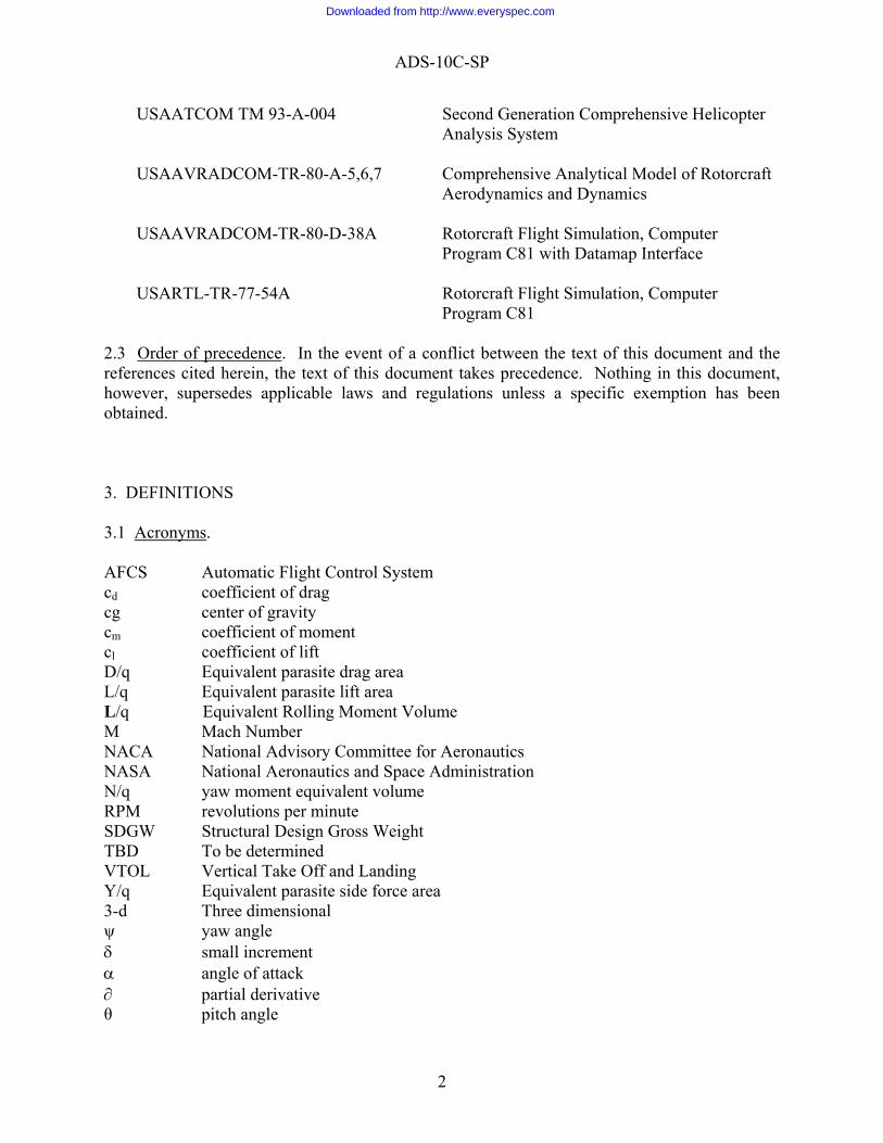
Program C81 2.3 Order of precedence. In the event of a conflict between the text of this document and the references cited herein, the text of this document takes precedence. Nothing in this document, however, supersedes applicable laws and regulations unless a specific exemption has been obtained. 3. DEFINITIONS 3.1 Acronyms. AFCS Automatic Flight Control System cd coefficient of drag cg center of gravity cm coefficient of moment cl coefficient of lift D/q Equivalent parasite drag area L/q Equivalent parasite lift area L/q Equivalent Rolling Moment Volume M Mach Number NACA National Advisory Committee for Aeronautics NASA National Aeronautics and Space Administration N/q yaw moment equivalent volume RPM revolutions per minute SDGW Structural Design Gross Weight TBD To be determined VTOL Vertical Take Off and Landing Y/q Equivalent parasite side force area 3-d Three dimensional ψ yaw angle δ small increment α angle of attack ∂ partial derivative θ pitch angle
2
Downloaded from http://www.everyspec.com
ADS-10C-SP
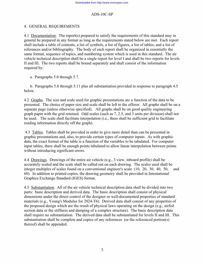
4. GENERAL REQUIREMENTS 4.1 Documentation. The report(s) prepared to satisfy the requirements of this standard may in general be prepared in any format as long as the requirements stated below are met. Each report shall include a table of contents, a list of symbols, a list of figures, a list of tables, and a list of references and/or bibliography. The body of each report shall be organized in essentially the same format, sequence of topics, and numbering system which is used in this standard. The air vehicle technical description shall be a single report for level I and shall be two reports for levels II and III. The two reports shall be bound separately and shall consist of the information required by: a. Paragraphs 5.0 through 5.7. b. Paragraphs 5.8 through 5.11 plus all substantiation provided in response to paragraph 4.5 below. 4.2 Graphs. The size and scale used for graphic presentations are a function of the data to be presented. The choice of paper size and scale shall be left to the offeror. All graphs shall be on a separate page (unless otherwise specified). All graphs shall be on good quality engineering graph paper with the grid retained. Odd scales (such as 7, 2.5, and 3 units per division) shall not be used. The scale shall facilitate interpolation (i.e., there shall be sufficient grid to facilitate reading information directly off the graph). 4.3 Tables. Tables shall be provided in order to give more detail than can be presented in graphic presentations and, also, to provide certain types of computer inputs. As with graphic data, the exact format of the table is a function of the variables to be tabulated. For computer input tables, there shall be enough points tabulated to allow linear interpolation between points without introducing significant errors. 4.4 Drawings. Drawings of the entire air vehicle (e.g., 3 view, inboard profile) shall be accurately scaled and the scale shall be called out on each drawing. The scales used shall be integer multiples of scales found on a conventional engineer's scale (10, 20, 30, 40, 50, and 60). In addition to printed copies, the drawing geometry shall be provided in International Graphics Exchange Standard (IGES) format. 4.5 Substantiation. All of the air vehicle technical description data shall be divided into two parts: basic description and derived data. The basic description shall consist of physical dimensions under the direct control of the designer or well-documented properties of standard materials (e.g., Young's Modulus for 2024-T6). Derived data shall consist of any properties of the proposed design which are the result of physical laws operating on the design (e.g., airfoil section data or the stiffness and damping of a complex structure). The basic description data shall require no substantiation. The derived data shall be substantiated for levels II and III. This substantiation shall be complete and copies of any references (or the referenced portion(s) thereof) shall be appended.
3
Downloaded from http://www.everyspec.com
ADS-10C-SP
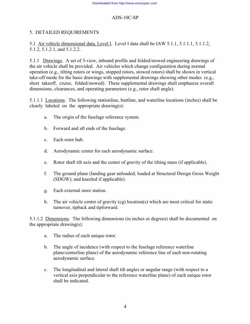
5. DETAILED REQUIREMENTS 5.1 Air vehicle dimensional data, Level I. Level I data shall be IAW 5.1.1, 5.1.1.1, 5.1.1.2, 5.1.2, 5.1.2.1, and 5.1.2.2. 5.1.1 Drawings. A set of 3-view, inboard profile and folded/stowed engineering drawings of the air vehicle shall be provided. Air vehicles which change configuration during normal operation (e.g., tilting rotors or wings, stopped rotors, stowed rotors) shall be shown in vertical take-off mode for the basic drawings with supplemental drawings showing other modes (e.g., short takeoff, cruise, folded/stowed). These supplemental drawings shall emphasize overall dimensions, clearances, and operating parameters (e.g., rotor shaft angle). 5.1.1.1 Locations. The following stationline, buttline, and waterline locations (inches) shall be clearly labeled on the appropriate drawing(s):
a. The origin of the fuselage reference system. b. Forward and aft ends of the fuselage. c. Each rotor hub. d. Aerodynamic center for each aerodynamic surface. e. Rotor shaft tilt axis and the center of gravity of the tilting mass (if applicable). f. The ground plane (landing gear unloaded; loaded at Structural Design Gross Weight
(SDGW); and kneeled if applicable). g. Each external store station. h. The air vehicle center of gravity (cg) location(s) which are most critical for static
turnover, tipback and tipforward. 5.1.1.2 Dimensions. The following dimensions (in inches or degrees) shall be documented on the appropriate drawing(s):
a. The radius of each unique rotor. b. The angle of incidence (with respect to the fuselage reference waterline
plane/centerline plane) of the aerodynamic reference line of each non-rotating aerodynamic surface.
c. The longitudinal and lateral shaft tilt angles or angular range (with respect to a
vertical axis perpendicular to the reference waterline plane) of each unique rotor shall be indicated.
4
Downloaded from http://www.everyspec.com
ADS-10C-SP
d. The static and dynamic (rotors turning) clearances of the most critical rotor blade(s) with respect to the rest of the air vehicle and/or the ground plane (landing gear loaded at SDGW).
e. The most critical static turnover, tipback and tipforward angles. f. The air vehicle overall length, width and height (rotors on and off). g. The maximum airframe width, landing gear retracted and extended (without
aerodynamic surfaces). h. The static and dynamic (limit sink speed landing) clearances of the most critical non-
rotating components with respect to the ground or deck for the most critical operating condition(s) including slope landings and rolling decks.
i. Cargo compartment, door, and ramp dimensions.
5.1.2 Tabulated Dimensions and Areas. 5.1.2.1 Airframe. The dimensions required on the drawings shall be tabulated in a compact format for easy reference. All angles shall be in degrees and linear dimensions shall be converted into feet, except for clearances in inches. The following items (feet or feet2) shall be added to this table.
a. Horizontal and/or vertical distance(s) between rotors. b. Landing gear track and tread (feet) plus the stationline and buttline location of the
center of each ground contact patch (inches). c. Cargo compartment floor area. d. Wetted areas of the following mutually exclusive components: fuselage, sponsons,
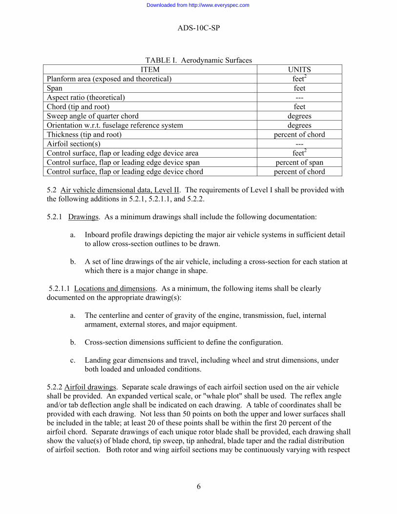
nacelle(s), pylon(s), and spinner(s)/hub fairing(s). 5.1.2.2 Aerodynamic Surfaces. As a minimum, the data per Table I shall be tabulated for each aerodynamic surface (excluding rotor blades).
5
Downloaded from http://www.everyspec.com
ADS-10C-SP
TABLE I. Aerodynamic Surfaces
ITEM UNITS Planform area (exposed and theoretical) feet2 Span feet Aspect ratio (theoretical) --- Chord (tip and root) feet Sweep angle of quarter chord degrees Orientation w.r.t. fuselage reference system degrees Thickness (tip and root) percent of chord Airfoil section(s) --- Control surface, flap or leading edge device area feet2 Control surface, flap or leading edge device span percent of span Control surface, flap or leading edge device chord percent of chord 5.2 Air vehicle dimensional data, Level II. The requirements of Level I shall be provided with the following additions in 5.2.1, 5.2.1.1, and 5.2.2. 5.2.1 Drawings. As a minimum drawings shall include the following documentation:
a. Inboard profile drawings depicting the major air vehicle systems in sufficient detail to allow cross-section outlines to be drawn.
b. A set of line drawings of the air vehicle, including a cross-section for each station at
which there is a major change in shape. 5.2.1.1 Locations and dimensions. As a minimum, the following items shall be clearly documented on the appropriate drawing(s):
a. The centerline and center of gravity of the engine, transmission, fuel, internal armament, external stores, and major equipment.
b. Cross-section dimensions sufficient to define the configuration. c. Landing gear dimensions and travel, including wheel and strut dimensions, under
both loaded and unloaded conditions. 5.2.2 Airfoil drawings. Separate scale drawings of each airfoil section used on the air vehicle shall be provided. An expanded vertical scale, or "whale plot" shall be used. The reflex angle and/or tab deflection angle shall be indicated on each drawing. A table of coordinates shall be provided with each drawing. Not less than 50 points on both the upper and lower surfaces shall be included in the table; at least 20 of these points shall be within the first 20 percent of the airfoil chord. Separate drawings of each unique rotor blade shall be provided, each drawing shall show the value(s) of blade chord, tip sweep, tip anhedral, blade taper and the radial distribution of airfoil section. Both rotor and wing airfoil sections may be continuously varying with respect
6
Downloaded from http://www.everyspec.com
ADS-10C-SP
to radius or span. In this case, primary airfoil section drawings and the radial location of such airfoils, shall be provided. 5.3 Air vehicle dimensional data, Level III. In addition to the Level II requirements, as a minimum, the following drawings shall also be documented. . 5.3.1 Basic drawings. Basic drawings shall contain a three-view drawing which shall include the overall dimensions, and an inboard drawing profile. 5.3.2 Structure drawings. Structure drawings shall contain direct and cross-sectional views (not isometric) accurately scaled, which shall include or be attached to the drawing, with details and dimensions that show the following:
a. Wing – Structural box including box chord and thickness along the span, typical cross sections showing flaps, slats, etc. engine location and centroids, dimensions and areas for flaps, slats, ailerons, spoilers, leading edge, trailing edge, major cutouts, etc., fold and production joints, materials used, critical temperature areas with design temperatures. Areas shall be shown in square feet and identified by cross hatching or other suitable means.
b. Tail- Drawings and information compatible with wing requirement where applicable. c. Rotor – Hub and hinge, including method of rotor attachment, typical cross section
including any balance weight, structural box, rotor chord and thickness along the span. Blade area in square feet identified by cross hatching or suitable means.
d. Fuselage, hull, and booms – Primary and secondary structure including bulkheads,
frames, longerons and stingers, major cutouts, flooring, major fittings and splices, pressurized area including volume, materials, critical temperature areas with design temperatures indicated. Fuel tank areas shall be cross hatched and capacities indicated (where not shown on a separate fuel system drawing). Major cutouts, weapons bays, store provisions, engine, engine compartment and access doors, landing gear support and cutout shall be identified.
e. Nacelle – Primary and secondary structure with details compatible with wing and
fuselage requirements when applicable. f. Air induction system – Details may be included on a separate drawing or included on
the fuselage or nacelle drawings. Inlet design including spike, ramp, mechanisms, etc., shall be shown.
g. Alighting gear – Main, nose, or tail, and auxiliary gear drawings detailing the gear
structure, rolling stock, retracting mechanism, attachment fittings, catapult and arrest structure. Sizes and dimensions are to be included for the rolling stock, oleo, travel, wheel travel (where different from oleo travel), strut length from axle to centerline trunnion.
7
Downloaded from http://www.everyspec.com
ADS-10C-SP
5.3.3 Propulsion system drawings. Propulsion system drawings shall include the following:
a. Engine – Location and shape, mounts, access provisions, intake attachment station, etc. (unless shown on the fuselage or nacelle structural drawings). Bleed or bypass ducts not shown on the basic air induction drawing.
b. Fuel system – Tank location, shapes, and capacities as well as location of the major
distribution system components. c. Transmission system – Gear boxes and supports, drive shafts and supports, from
engine to final output drive points. Horsepower, torque, RPM, and gear ratios shall be shown for each stage.
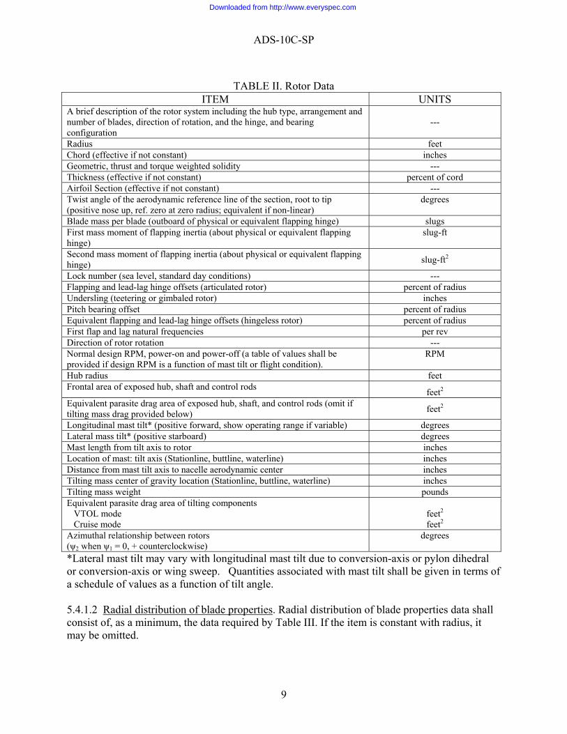
5.3.4 Equipment drawings. Equipment drawings shall be scaled drawings to show major component locations and schematics to show the functional layout of the flight control, mission equipment avionics, hydraulic, pneumatic, electrical, air conditioning, and anti-icing groups. Isometric drawings may be substituted. 5.4 Description of the rotor systems. Data describing the rotor systems shall be divided into two categories: 1) information which describes the total system, and 2) those properties which vary with radius. The tabulation shall be compact and shall exclude any items not applicable to the type of rotor system proposed. Both graphic and tabular data shall be used in describing the radially varying properties. Not less than 20 nor more than 50 blade stations shall be used (if the property is piecewise linear, break points only shall be used). Blade stations should be spaced in such a way as to insure accurate interpolation. Radially varying properties shall be documented from the center of rotation to the blade tip. Properties which vary with collective pitch shall be documented for three values of collective pitch (minimum, middle and maximum). Properties which vary with operating mode (e.g., hover, cruise) shall be documented for each significant operating mode. The following data shall be documented for each unique rotor system and propeller, if applicable. 5.4.1 Level I. Level I data shall be as specified in 5.4.1.1 and 5.4.1.2. 5.4.1.1 Rotor Data. Rotor data shall consist of, as a minimum, the data required by Table II.
8
Downloaded from http://www.everyspec.com
ADS-10C-SP
TABLE II. Rotor Data
ITEM UNITS A brief description of the rotor system including the hub type, arrangement and number of blades, direction of rotation, and the hinge, and bearing configuration
---
Radius feet Chord (effective if not constant) inches Geometric, thrust and torque weighted solidity --- Thickness (effective if not constant) percent of cord Airfoil Section (effective if not constant) --- Twist angle of the aerodynamic reference line of the section, root to tip (positive nose up, ref. zero at zero radius; equivalent if non-linear)
degrees
Blade mass per blade (outboard of physical or equivalent flapping hinge) slugs First mass moment of flapping inertia (about physical or equivalent flapping hinge)
slug-ft
Second mass moment of flapping inertia (about physical or equivalent flapping hinge) slug-ft2
Lock number (sea level, standard day conditions) --- Flapping and lead-lag hinge offsets (articulated rotor) percent of radius Undersling (teetering or gimbaled rotor) inches Pitch bearing offset percent of radius Equivalent flapping and lead-lag hinge offsets (hingeless rotor) percent of radius First flap and lag natural frequencies per rev Direction of rotor rotation --- Normal design RPM, power-on and power-off (a table of values shall be provided if design RPM is a function of mast tilt or flight condition).
RPM
Hub radius feet Frontal area of exposed hub, shaft and control rods feet2 Equivalent parasite drag area of exposed hub, shaft, and control rods (omit if tilting mass drag provided below) feet2
Longitudinal mast tilt* (positive forward, show operating range if variable) degrees Lateral mass tilt* (positive starboard) degrees Mast length from tilt axis to rotor inches Location of mast: tilt axis (Stationline, buttline, waterline) inches Distance from mast tilt axis to nacelle aerodynamic center inches Tilting mass center of gravity location (Stationline, buttline, waterline) inches Tilting mass weight pounds Equivalent parasite drag area of tilting components VTOL mode Cruise mode
feet2
feet2 Azimuthal relationship between rotors (ψ2 when ψ1 = 0, + counterclockwise)
degrees
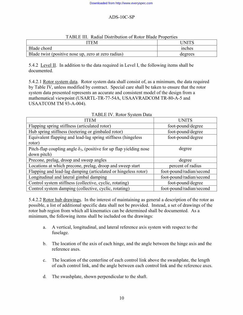
*Lateral mast tilt may vary with longitudinal mast tilt due to conversion-axis or pylon dihedral or conversion-axis or wing sweep. Quantities associated with mast tilt shall be given in terms of a schedule of values as a function of tilt angle. 5.4.1.2 Radial distribution of blade properties. Radial distribution of blade properties data shall consist of, as a minimum, the data required by Table III. If the item is constant with radius, it may be omitted.
9
Downloaded from http://www.everyspec.com
ADS-10C-SP
TABLE III. Radial Distribution of Rotor Blade Properties
ITEM UNITS Blade chord inches Blade twist (positive nose up, zero at zero radius) degrees 5.4.2 Level II. In addition to the data required in Level I, the following items shall be documented. 5.4.2.1 Rotor system data. Rotor system data shall consist of, as a minimum, the data required by Table IV, unless modified by contract. Special care shall be taken to ensure that the rotor system data presented represents an accurate and consistent model of the design from a mathematical viewpoint (USARTL-TR-77-54A, USAAVRADCOM TR-80-A-5 and USAATCOM TM 93-A-004).
TABLE IV. Rotor System Data ITEM UNITS
Flapping spring stiffness (articulated rotor) foot-pound/degree Hub spring stiffness (teetering or gimbaled rotor) foot-pound/degree Equivalent flapping and lead-lag spring stiffness (hingeless rotor)
foot-pound/degree
Pitch-flap coupling angle δ3, (positive for up flap yielding nose down pitch)
degree
Precone, prelag, droop and sweep angles degree Locations at which precone, prelag, droop and sweep start percent of radius Flapping and lead-lag damping (articulated or hingeless rotor) foot-pound/radian/second Longitudinal and lateral gimbal damping foot-pound/radian/second Control system stiffness (collective, cyclic, rotating) foot-pound/degree Control system damping (collective, cyclic, rotating) foot-pound/radian/second 5.4.2.2 Rotor hub drawings. In the interest of maintaining as general a description of the rotor as possible, a list of additional specific data shall not be provided. Instead, a set of drawings of the rotor hub region from which all kinematics can be determined shall be documented. As a minimum, the following items shall be included on the drawings:
a. A vertical, longitudinal, and lateral reference axis system with respect to the fuselage.
b. The location of the axis of each hinge, and the angle between the hinge axis and the
reference axes. c. The location of the centerline of each control link above the swashplate, the length
of each control link, and the angle between each control link and the reference axes. d. The swashplate, shown perpendicular to the shaft.
10
Downloaded from http://www.everyspec.com
ADS-10C-SP
e. The orientation of the blade spanwise axes with respect to the reference axes (i.e., rotor blade droop, sweep, coning, pretwist, etc.)
f. The location and orientation of all spring and damper forces and moments. g. The location of all mechanical coupling points and the line of action of all forces
through them. h. All rotor blade or hub mounted vibration reduction devices.
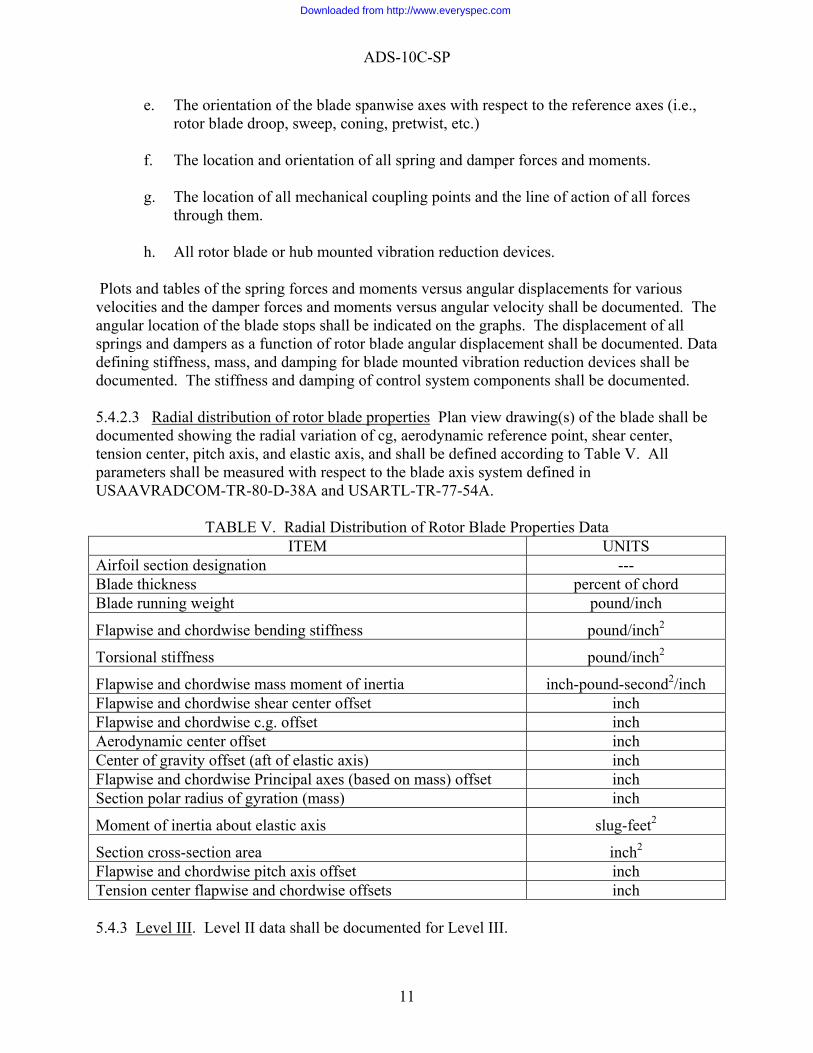
Plots and tables of the spring forces and moments versus angular displacements for various velocities and the damper forces and moments versus angular velocity shall be documented. The angular location of the blade stops shall be indicated on the graphs. The displacement of all springs and dampers as a function of rotor blade angular displacement shall be documented. Data defining stiffness, mass, and damping for blade mounted vibration reduction devices shall be documented. The stiffness and damping of control system components shall be documented. 5.4.2.3 Radial distribution of rotor blade properties Plan view drawing(s) of the blade shall be documented showing the radial variation of cg, aerodynamic reference point, shear center, tension center, pitch axis, and elastic axis, and shall be defined according to Table V. All parameters shall be measured with respect to the blade axis system defined in USAAVRADCOM-TR-80-D-38A and USARTL-TR-77-54A.
TABLE V. Radial Distribution of Rotor Blade Properties Data ITEM UNITS
Airfoil section designation --- Blade thickness percent of chord Blade running weight pound/inch
Flapwise and chordwise bending stiffness pound/inch2
Torsional stiffness pound/inch2
Flapwise and chordwise mass moment of inertia inch-pound-second2/inch Flapwise and chordwise shear center offset inch Flapwise and chordwise c.g. offset inch Aerodynamic center offset inch Center of gravity offset (aft of elastic axis) inch Flapwise and chordwise Principal axes (based on mass) offset inch Section polar radius of gyration (mass) inch
Moment of inertia about elastic axis slug-feet2
Section cross-section area inch2 Flapwise and chordwise pitch axis offset inch Tension center flapwise and chordwise offsets inch 5.4.3 Level III. Level II data shall be documented for Level III.
11
Downloaded from http://www.everyspec.com
ADS-10C-SP
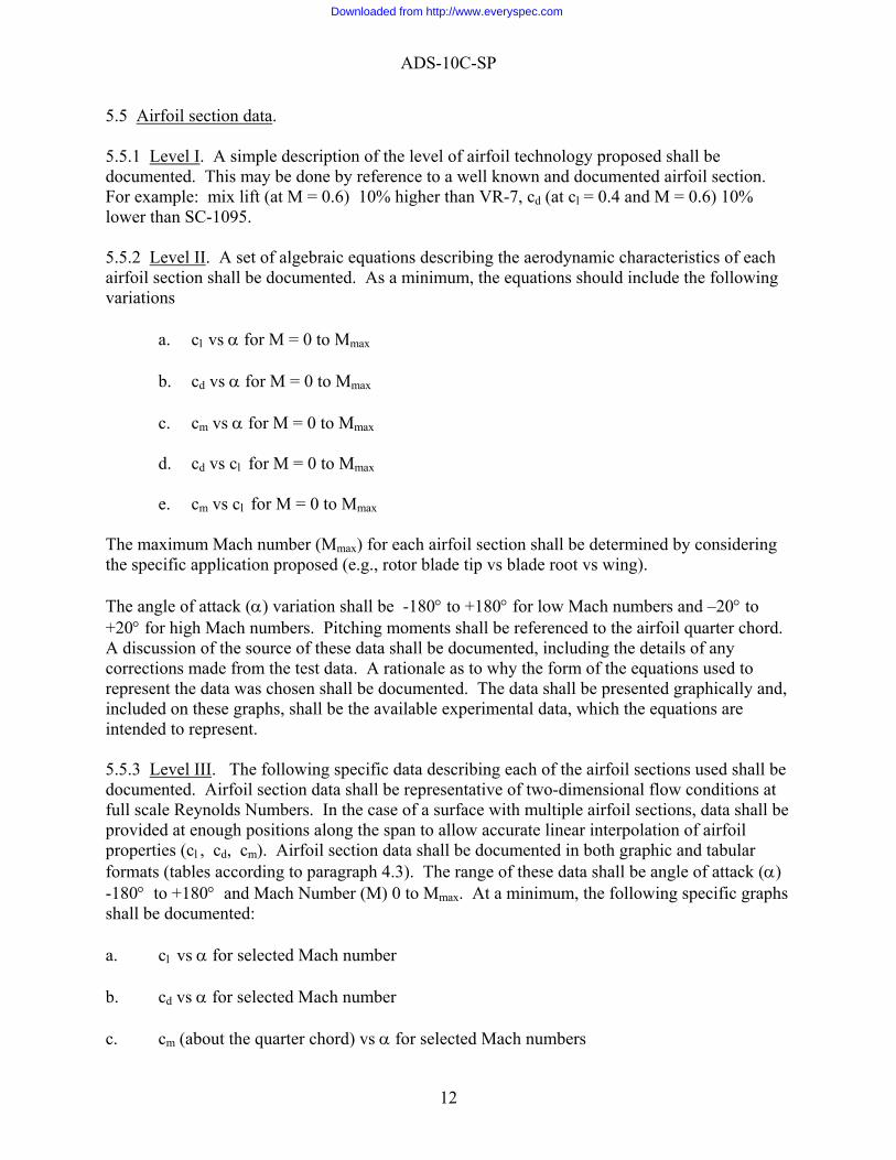
5.5 Airfoil section data. 5.5.1 Level I. A simple description of the level of airfoil technology proposed shall be documented. This may be done by reference to a well known and documented airfoil section. For example: mix lift (at M = 0.6) 10% higher than VR-7, cd (at cl = 0.4 and M = 0.6) 10% lower than SC-1095. 5.5.2 Level II. A set of algebraic equations describing the aerodynamic characteristics of each airfoil section shall be documented. As a minimum, the equations should include the following variations
a. cl vs α for M = 0 to Mmax b. cd vs α for M = 0 to Mmax c. cm vs α for M = 0 to Mmax d. cd vs cl for M = 0 to Mmax e. cm vs cl for M = 0 to Mmax
The maximum Mach number (Mmax) for each airfoil section shall be determined by considering the specific application proposed (e.g., rotor blade tip vs blade root vs wing). The angle of attack (α) variation shall be -180° to +180° for low Mach numbers and –20° to +20° for high Mach numbers. Pitching moments shall be referenced to the airfoil quarter chord. A discussion of the source of these data shall be documented, including the details of any corrections made from the test data. A rationale as to why the form of the equations used to represent the data was chosen shall be documented. The data shall be presented graphically and, included on these graphs, shall be the available experimental data, which the equations are intended to represent. 5.5.3 Level III. The following specific data describing each of the airfoil sections used shall be documented. Airfoil section data shall be representative of two-dimensional flow conditions at full scale Reynolds Numbers. In the case of a surface with multiple airfoil sections, data shall be provided at enough positions along the span to allow accurate linear interpolation of airfoil properties (cl , cd, cm). Airfoil section data shall be documented in both graphic and tabular formats (tables according to paragraph 4.3). The range of these data shall be angle of attack (α) -180° to +180° and Mach Number (M) 0 to Mmax. At a minimum, the following specific graphs shall be documented: a. cl vs α for selected Mach number b. cd vs α for selected Mach number c. cm (about the quarter chord) vs α for selected Mach numbers
12
Downloaded from http://www.everyspec.com
ADS-10C-SP
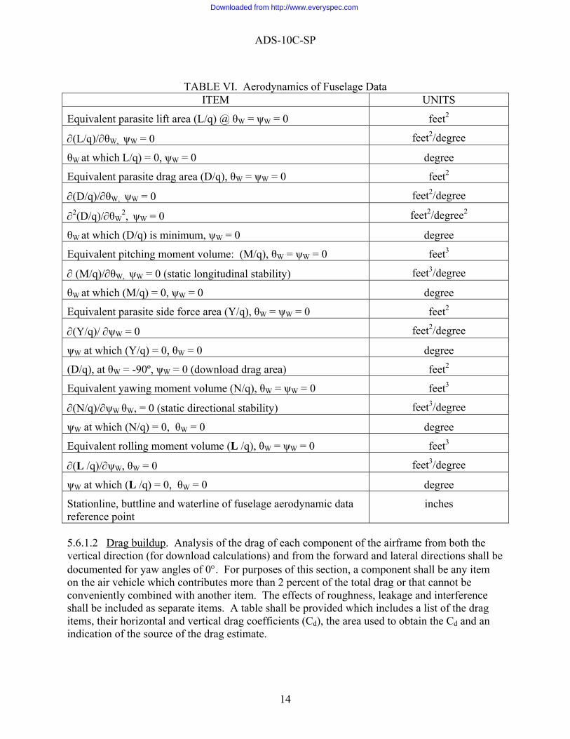
d. cl vs M for selected angles of attack e. cd vs M for selected angles of attack f. cm (about the quarter chord) vs M for selected angles of attack g. cd vs cl for selected Mach numbers h. cm vs cl for selected Mach numbers Sliding scales may be used for graphs if the requirements for interpolation are met. A complete description of the source of the data, including a description of any corrections made, shall be documented. (See 6.3) The final data shall be representative of airfoil force coefficients resulting from those measured in two-dimensional flow at full scale Reynolds Numbers. The computer program described in NASA TM-78627 may be used to generate the computer deck of the airfoil data. 5.6 Airframe aerodynamic data. The following specific aerodynamic data describing the rotorcraft airframe shall be provided for all normal modes of flight. The data shall be documented in the wind axis system. The location of the point at which the forces and moments are defined to be acting (the aerodynamic reference point) shall be identified. The forces and moments shall be normalized by dynamic pressure such that the units are feet2 and feet3. 5.6.1 Level I. 5.6.1.1 Aerodynamics of the fuselage. For the purposes of this section, the fuselage shall be defined in such a way as to exclude all items in paragraphs 5.4 (rotor system) and 5.9 (aerodynamic surfaces). Fuselage aerodynamics data shall be documented according to Table VI. (NOTE: θW = pitch angle, Wind axis; ψW = yaw angle, wind axis; use a unit reference area)
13
Downloaded from http://www.everyspec.com
ADS-10C-SP
TABLE VI. Aerodynamics of Fuselage Data
ITEM UNITS
Equivalent parasite lift area (L/q) @ θW = ψW = 0 feet2
∂(L/q)/∂θW, ψW = 0 feet2/degree
θW at which L/q) = 0, ψW = 0 degree
Equivalent parasite drag area (D/q), θW = ψW = 0 feet2
∂(D/q)/∂θW, ψW = 0 feet2/degree
∂2(D/q)/∂θW2, ψW = 0 feet2/degree2
θW at which (D/q) is minimum, ψW = 0 degree
Equivalent pitching moment volume: (M/q), θW = ψW = 0 feet3
∂ (M/q)/∂θW, ψW = 0 (static longitudinal stability) feet3/degree
θW at which (M/q) = 0, ψW = 0 degree
Equivalent parasite side force area (Y/q), θW = ψW = 0 feet2
∂(Y/q)/ ∂ψW = 0 feet2/degree
ψW at which (Y/q) = 0, θW = 0 degree
(D/q), at θW = -90º, ψW = 0 (download drag area) feet2
Equivalent yawing moment volume (N/q), θW = ψW = 0 feet3
∂(N/q)/∂ψW θW, = 0 (static directional stability) feet3/degree
ψW at which (N/q) = 0, θW = 0 degree
Equivalent rolling moment volume (L /q), θW = ψW = 0 feet3
∂(L /q)/∂ψW, θW = 0 feet3/degree
ψW at which (L /q) = 0, θW = 0 degree
Stationline, buttline and waterline of fuselage aerodynamic data reference point
inches
5.6.1.2 Drag buildup. Analysis of the drag of each component of the airframe from both the vertical direction (for download calculations) and from the forward and lateral directions shall be documented for yaw angles of 0°. For purposes of this section, a component shall be any item on the air vehicle which contributes more than 2 percent of the total drag or that cannot be conveniently combined with another item. The effects of roughness, leakage and interference shall be included as separate items. A table shall be provided which includes a list of the drag items, their horizontal and vertical drag coefficients (Cd), the area used to obtain the Cd and an indication of the source of the drag estimate.
14
Downloaded from http://www.everyspec.com
ADS-10C-SP
5.6.1.3 Stability and control derivatives. Tables of stability and control derivatives for hover and cruise airspeed at SDGW in primary mission configuration shall be documented. A description of the method used to obtain the derivatives shall be included. 5.6.2 Level II. In addition to all Level I items, the following specific data shall be documented. 5.6.2.1 Aerodynamics of the airframe. The aerodynamic forces and moments (normalized to free stream dynamic pressure) generated by the entire airframe (including aerodynamic surfaces) shall be documented in graphic and tabular form. The forces shall be documented as a function of yaw angles which vary from -20° to +20° at zero pitch angle and as a function of pitch angles which vary from -20° to +20° at zero yaw angle. The forces and moments generated at yaw angles of +90°, -90°, and 180° at zero pitch angle and pitch angles of -90° and +90°, at zero yaw angle shall also be documented. 5.6.2.2 In addition to the Level I requirements of Section 5.6.1.3 tables of stability and control derivatives shall be documented to assess the effects of altitude, center-of-gravity and gross weight variations. 5.6.3 Level III. The data required by Section 5.6.2 shall be provided in addition to the following. 5.6.3.1 Component aerodynamics. The airframe aerodynamic forces and moments (normalized to free stream dynamic pressure) generated with each of the major components removed separately shall be documented in graphic form. The forces shall be presented as a function of yaw angles which vary from -20° to +20° and as a function of pitch angles which vary from -20° to +20° (matrix of forces and moments). The aerodynamic forces and moments generated with and without the empennage at yaw angles of +90°, -90°, and 180° shall also be documented. (See 6.2 for further information.) 5.7 Rotor structural dynamics data. 5.7.1 Level I. No data required. 5.7.2 Level II. 5.7.2.1 Blade mode shapes. Rotor blade mode data shall be documented in graphic and tabular form. As a minimum, the following specific items shall be provided:
a. A Southwell (fan) plot of the rotor natural frequencies for fully coupled modes showing at least the first 2N/rev frequencies, including the effect of collective pitch. (N = number of rotor blades.)
b. Plots of the mode shapes at design, power-on RPM for the modes identified in Item a. c. Plots of the mode shapes at minimum and maximum power-on and power-off RPM
for the modes identified in paragraph a. above.
15
Downloaded from http://www.everyspec.com
ADS-10C-SP
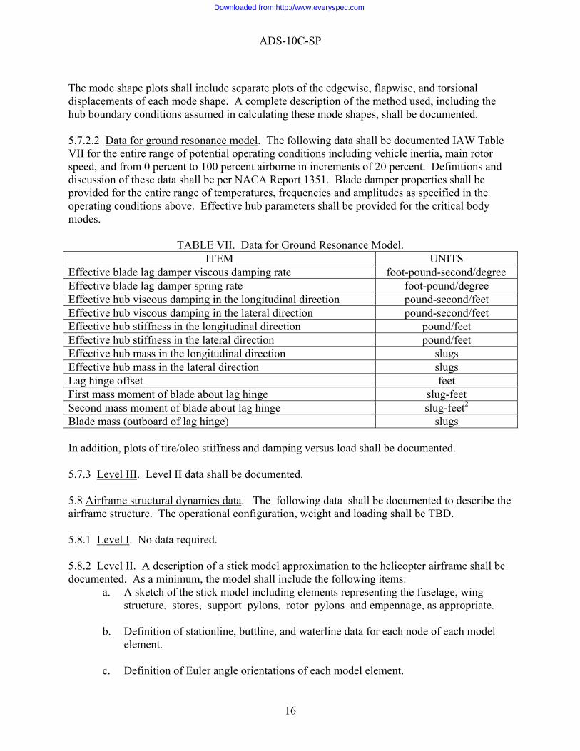
The mode shape plots shall include separate plots of the edgewise, flapwise, and torsional displacements of each mode shape. A complete description of the method used, including the hub boundary conditions assumed in calculating these mode shapes, shall be documented. 5.7.2.2 Data for ground resonance model. The following data shall be documented IAW Table VII for the entire range of potential operating conditions including vehicle inertia, main rotor speed, and from 0 percent to 100 percent airborne in increments of 20 percent. Definitions and discussion of these data shall be per NACA Report 1351. Blade damper properties shall be provided for the entire range of temperatures, frequencies and amplitudes as specified in the operating conditions above. Effective hub parameters shall be provided for the critical body modes.
TABLE VII. Data for Ground Resonance Model. ITEM UNITS
Effective blade lag damper viscous damping rate foot-pound-second/degree Effective blade lag damper spring rate foot-pound/degree Effective hub viscous damping in the longitudinal direction pound-second/feet Effective hub viscous damping in the lateral direction pound-second/feet Effective hub stiffness in the longitudinal direction pound/feet Effective hub stiffness in the lateral direction pound/feet Effective hub mass in the longitudinal direction slugs Effective hub mass in the lateral direction slugs Lag hinge offset feet First mass moment of blade about lag hinge slug-feet Second mass moment of blade about lag hinge slug-feet2 Blade mass (outboard of lag hinge) slugs In addition, plots of tire/oleo stiffness and damping versus load shall be documented. 5.7.3 Level III. Level II data shall be documented. 5.8 Airframe structural dynamics data. The following data shall be documented to describe the airframe structure. The operational configuration, weight and loading shall be TBD. 5.8.1 Level I. No data required. 5.8.2 Level II. A description of a stick model approximation to the helicopter airframe shall be documented. As a minimum, the model shall include the following items:
a. A sketch of the stick model including elements representing the fuselage, wing structure, stores, support pylons, rotor pylons and empennage, as appropriate.
b. Definition of stationline, buttline, and waterline data for each node of each model
element. c. Definition of Euler angle orientations of each model element.
16
Downloaded from http://www.everyspec.com
ADS-10C-SP
d. Definition of elastic and inertial properties of each model element.
5.8.3 Level III. A detailed finite element model of the airframe and any information necessary to reproduce the modal data requested below shall be documented. 5.8.3.1 Airframe modal data. As a minimum, the following modal data shall be documented.
a. The generalized masses, frequencies, and damping of each airframe mode up to 4N/rev (N = number of rotor blades for primary lift rotor(s)).
b. Modal displacements at each rotor hub employing six degrees of freedom at each
mode (x, y, z translations and 3 corresponding rotations). c. Modal displacements at the following locations on the airframe.
(l) Pilot and co-pilot positions (2) Points at which stores are attached. (3) Points at which wing stabilizing surfaces and stores support pylons are attached. (4) Selected points at which specified forces may act (for example, forces to be
used to simulate shake test or for other known excitations). (5) Points at which vibration absorbers and isolation devices are attached. (6) Points at which visionic packages are attached.
5.8.3.2 Description of airframe-mounted absorbers and isolators. As a minimum, the following data shall be documented for the airframe-mounted absorbers and isolators:
a. The stiffness, mass, and damping properties for vibration devices such as airframe-mounted absorbers, isolators and hub-mounted absorbers. Define the stationline, buttline, and waterline coordinates for points connection of such components to the airframe.
b. An engineering drawing that clearly defines the specific configuration and
installation of all vibration absorption and isolation devices.
5.9 Aerodynamic surface data. The following data shall be documented for each non-rotating aerodynamic surface.
5.9.1 Level I.
5.9.2 Level II. Level II data shall be documented per 5.9.2.1.
17
Downloaded from http://www.everyspec.com
ADS-10C-SP
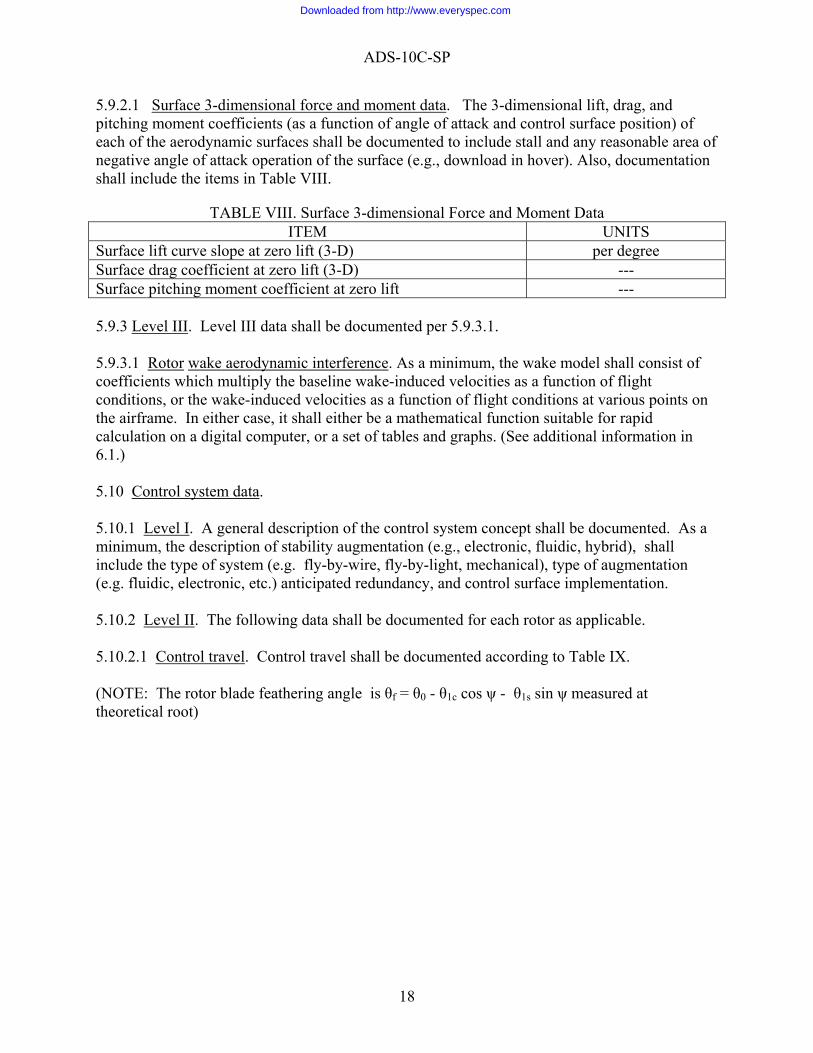
5.9.2.1 Surface 3-dimensional force and moment data. The 3-dimensional lift, drag, and pitching moment coefficients (as a function of angle of attack and control surface position) of each of the aerodynamic surfaces shall be documented to include stall and any reasonable area of negative angle of attack operation of the surface (e.g., download in hover). Also, documentation shall include the items in Table VIII.
TABLE VIII. Surface 3-dimensional Force and Moment Data ITEM UNITS
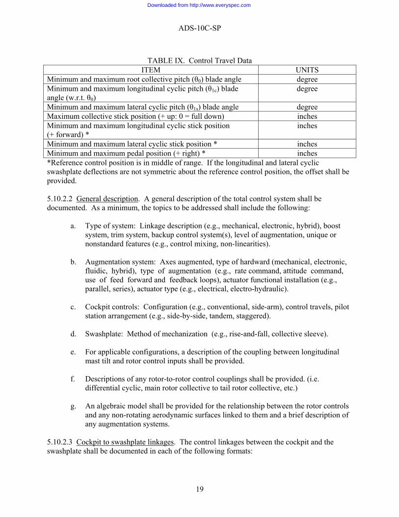
Surface lift curve slope at zero lift (3-D) per degree Surface drag coefficient at zero lift (3-D) --- Surface pitching moment coefficient at zero lift --- 5.9.3 Level III. Level III data shall be documented per 5.9.3.1. 5.9.3.1 Rotor wake aerodynamic interference. As a minimum, the wake model shall consist of coefficients which multiply the baseline wake-induced velocities as a function of flight conditions, or the wake-induced velocities as a function of flight conditions at various points on the airframe. In either case, it shall either be a mathematical function suitable for rapid calculation on a digital computer, or a set of tables and graphs. (See additional information in 6.1.) 5.10 Control system data. 5.10.1 Level I. A general description of the control system concept shall be documented. As a minimum, the description of stability augmentation (e.g., electronic, fluidic, hybrid), shall include the type of system (e.g. fly-by-wire, fly-by-light, mechanical), type of augmentation (e.g. fluidic, electronic, etc.) anticipated redundancy, and control surface implementation. 5.10.2 Level II. The following data shall be documented for each rotor as applicable. 5.10.2.1 Control travel. Control travel shall be documented according to Table IX. (NOTE: The rotor blade feathering angle is θf = θ0 - θ1c cos ψ - θ1s sin ψ measured at theoretical root)
18
Downloaded from http://www.everyspec.com
ADS-10C-SP
TABLE IX. Control Travel Data
ITEM UNITS Minimum and maximum root collective pitch (θ0) blade angle degree Minimum and maximum longitudinal cyclic pitch (θ1c) blade angle (w.r.t. θ0)
degree
Minimum and maximum lateral cyclic pitch (θ1s) blade angle degree Maximum collective stick position (+ up: 0 = full down) inches Minimum and maximum longitudinal cyclic stick position (+ forward) *
inches
Minimum and maximum lateral cyclic stick position * inches Minimum and maximum pedal position (+ right) * inches *Reference control position is in middle of range. If the longitudinal and lateral cyclic swashplate deflections are not symmetric about the reference control position, the offset shall be provided. 5.10.2.2 General description. A general description of the total control system shall be documented. As a minimum, the topics to be addressed shall include the following:
a. Type of system: Linkage description (e.g., mechanical, electronic, hybrid), boost system, trim system, backup control system(s), level of augmentation, unique or nonstandard features (e.g., control mixing, non-linearities).
b. Augmentation system: Axes augmented, type of hardward (mechanical, electronic,
fluidic, hybrid), type of augmentation (e.g., rate command, attitude command, use of feed forward and feedback loops), actuator functional installation (e.g., parallel, series), actuator type (e.g., electrical, electro-hydraulic).
c. Cockpit controls: Configuration (e.g., conventional, side-arm), control travels, pilot
station arrangement (e.g., side-by-side, tandem, staggered). d. Swashplate: Method of mechanization (e.g., rise-and-fall, collective sleeve). e. For applicable configurations, a description of the coupling between longitudinal
mast tilt and rotor control inputs shall be provided. f. Descriptions of any rotor-to-rotor control couplings shall be provided. (i.e.
differential cyclic, main rotor collective to tail rotor collective, etc.) g. An algebraic model shall be provided for the relationship between the rotor controls
and any non-rotating aerodynamic surfaces linked to them and a brief description of any augmentation systems.
5.10.2.3 Cockpit to swashplate linkages. The control linkages between the cockpit and the swashplate shall be documented in each of the following formats:
19
Downloaded from http://www.everyspec.com
ADS-10C-SP
a. Block diagram(s): Including such items as cockpit controls, boost/AFCS servos; control mixing; bunge springs and/or force feel system (break-out forces and gradients) pylon coupling; swashplate; sensors which drive servos, swashplate, or aerodynamic surfaces; control system stiffness, and linkage to aerodynamic surfaces.
b. Algebraic representation of items in block diagram(s): in particular, transfer functions for sensors, stabilization or control augmentation loops, and servos; control linkages; control mixing; and control stiffness.
5.10.2.4 Swashplate to blade linkages. The control of linkages between the swashplate and the rotor blades shall be documented in each of the following formats:
a. Block diagram(s): Including swashplate, control inputs from augmentation systems above the swashplate (e.g., stabilizer bar, control gyro), non-unity gearing in the control linkage servos, blade feathering angle, angular travel of swashplate and resulting blade feathering.
b. Algebraic representation of items in the block diagram(s): In particular, transfer
functions for augmentation systems, non-unity gearing. 5.10.3 Level III. In addition to the data required in Level II, a detailed algebraic representation of control system flexibility, nonlinearities and dynamics and tabular and graphic representations of the data in Sections 5.10.2.2 and 5.10.2.3 shall be documented. 5.11 Propulsion and drive system data. 5.11.1 Level I. A summary of all propulsion and drive system losses assumed for flight performance estimates shall be documented. All losses which affect the power available at the engine output shaft(s) shall be labeled "engine installation losses". All other losses or power requirements occurring between the engine output shaft(s) and the main rotor(s) shall be labeled “accessory losses" "drive system losses", or "anti-torque losses", as appropriate. Any variation of losses with air vehicle operating condition which is assumed for flight performance estimates shall be fully described. 6. NOTES 6.1 Rotor wake aerodynamic interference. Rotor wakes may impinge upon various parts of the airframe causing significant aerodynamic interference. The baseline model for these wakes is a uniform-inflow, momentum theory wake whose trajectory is determined by the wake induced velocity and the freestream. A more sophisticated wake model may be provided for interference calculations, if this is necessary to accurately model the proposed design. 6.2 Component aerodynamics. The definition of a "major component" is left to the discretion of the offeror; those items usually tested in a component buildup (e.g., fuselage, Wings, stores, landing gear and stabilizing surfaces) would be sufficient.
20
Downloaded from http://www.everyspec.com

ADS-10C-SP
6.3 Airfoil Level III data. Corrections include wind tunnel wall corrections, adjustments to the measured data to account for any other known wind tunnel inadequacies, and adjustments in data to account for "surface roughness". If insufficient or no wind tunnel tests of an airfoil section exist, then the procedure by which the data are estimated should be completely explained.
21
Downloaded from http://www.everyspec.com