aeronautics in the 00 cow lu of t
TRANSCRIPT

8/13/2019 Aeronautics in the 00 Cow Lu of t
http://slidepdf.com/reader/full/aeronautics-in-the-00-cow-lu-of-t 1/365
=00
iin
l(0
•(D
Ico
lt: :li;il'i ';'l' 'iljlH'
ill :M
\mm il
lit
w:^.m
ill

8/13/2019 Aeronautics in the 00 Cow Lu of t
http://slidepdf.com/reader/full/aeronautics-in-the-00-cow-lu-of-t 2/365
V-

8/13/2019 Aeronautics in the 00 Cow Lu of t
http://slidepdf.com/reader/full/aeronautics-in-the-00-cow-lu-of-t 3/365

8/13/2019 Aeronautics in the 00 Cow Lu of t
http://slidepdf.com/reader/full/aeronautics-in-the-00-cow-lu-of-t 4/365

8/13/2019 Aeronautics in the 00 Cow Lu of t
http://slidepdf.com/reader/full/aeronautics-in-the-00-cow-lu-of-t 5/365
^ AEliONAUTICS
IN THEORY AND EXPERIMENTBY
W. L. COWLEY, A.K.C.SC., D.I.O.
WHITWORTH SCHOLAK
AND
H. LEVY, M.A., D.Sc, F.R.S.E.
CARNEGIE RESEARCH FELLOW, LATE 1851 EXHIBITIONERAND FERGUSON SCHOLAR
SECOND EDITION
>>.
iMh*'-^l
LONDONEDWARD ARNOLD
1920
All rights reserved

8/13/2019 Aeronautics in the 00 Cow Lu of t
http://slidepdf.com/reader/full/aeronautics-in-the-00-cow-lu-of-t 6/365
Digitized by the Internet Archive
in 2007 with funding from
IVIicrosoft Corporation

8/13/2019 Aeronautics in the 00 Cow Lu of t
http://slidepdf.com/reader/full/aeronautics-in-the-00-cow-lu-of-t 7/365
^EFICE TO THE FIEST EDITION
A S a result of the stimulus of war, aeronautics has made such
r\_ gigantic strides during the past few years that it has
definitely attained the rank of a science, and will, it is anticipated,
shortly take its proper position in the curriculum of every uni-
versity and technical college.
The present volume is the outcome of an attempt to provide
a sound and scientific treatment of the fundamental principles
upon which the subject is based, and to indicate the hnes of
further development. The book, it is hoped, will thus satisfy a
rapidly increasing demand. War conditions have unfortunately
limited the authors considerably in the material of which they
might have availed themselves, but they have striven through-
out to present a sound theory, and only to utiHse data as a means
of exemplifying the appHcation of the principles enunciated;
it should accordingly be understood that certain of the data
may require to be slightly modified when the present restrictions
are removed. From this point of view, no apology is made for
presenting in Plates I, II, III a machine, not quite of the latest
type, for the purpose of explaining the relative importance and
positions of the various parts, and the form of structure of wing
and fuselage. Historically it illustrates the stage to which the
science had developed just prior to the outbreak of hostilities.
The importance of a thorough conception of the nature of
fluid motion in the study of aeronautics cannot be over-em-
phasised, and the authors hope that the manner of treatment
adopted will commend itself to the reader. Unfortunately the
mathematical development of this branch of the subject leads
to analysis of considerable complexity and consequently the
motion of a perfect fluid only has been dealt with to any extent
in this manner, although a few of the simpler cases of the flow
of a viscous fluid have also been included. For the student of
moderate mathematical abihty the treatment of the subject in
Chapter ii and the latter part of Chapter iii, where the fluid
is regarded from the molecular point of view, should suffice.
Associated with this, is the subject matter of Chapter iv, where

8/13/2019 Aeronautics in the 00 Cow Lu of t
http://slidepdf.com/reader/full/aeronautics-in-the-00-cow-lu-of-t 8/365
IV PREFACE TO THE FIRST EDITION
exemplified by illustrations from fluid motion, etc. The actual
application of the theory to the aerofoil and to the propeller is
dealt with in detail in the chapters treating specifically withthese parts.
The subject matter of Chapter viii on Strength of Construc-
tion it is felt is considerably curtailed, as it must be at the
present time, but it is proposed in a future edition to amplify
this section by the inclusion of later work on the critical loading
of struts and aeroplane structures generally, the calculation of
the force distributions on fuselages, and much experimentalresearch that has lately been brought to fruition.
No text book on Aeronautics can be complete without a
thorough discussion of stabihty both from the theoretical and
the experimental standpoint, so ably investigated by Bryan
and Bairstow. Once again the mathematics may appear for-
midable, but as far as possible the task of the student has been
lightened by full explanations of the mathematical methodsadopted. To this end, the equations of moving axes have been
derived as simply and as clearly as possible in order that the
student whose knowledge of mathematics is hmited may succeed
in driving through this section of the subject without the heart-
breaking despair frequently associated with it. Many of the equa-
tions could have been derived equally well with reference to fixed
axes, but thework
in its laterdevelopment, e.g. in the treatment
of laterals, would have become exceedingly comphcated.
Every serious student must reahse that a mastery of stability
is an essential for the study of the problem of safe flight, and
perseverance is the only advice that can be offered.
The authors would like to express their thanks to Sir Kichard
Glazebrook, P.R.S., Director of the National Physical Laboratory,
to Dr Stanton, F.R.S., Superintendent of theAerodynamics
Division of the N.P.L., and to Mr Bairstow, F.R.S., C.B.E., for
their valuable criticism of the manner of presentation, and for
the facihties afforded in the use of material. Thanks are also
due to the Advisory Committee for Aeronautics for the use of
the half-tones and for permission to publish much of the subject
matter.

8/13/2019 Aeronautics in the 00 Cow Lu of t
http://slidepdf.com/reader/full/aeronautics-in-the-00-cow-lu-of-t 9/365
PREFACE TO THE SECOND EDITION
THE two years that have elapsed since the issue of the first
edition of this book have seen a flood of aeronautical literature
poured upon the market, covering almost every aspect of the
problem of flight both in relation to navigation and design. The
authors have consequently not attempted in this edition to
provide anything of the nature of an elaborate compendium of
up-to-date design data, but have rather scrutinised carefully the
fundamental principles enunciated in the previous edition where
fuller knowledge and experience have provided a wider and
deeper insight. In all instances more modern and more accurate
experimental data have been substituted in the illustrative
examples, where necessary, but the general sequence of the book
is substantially unaltered. Criticism and review have confirmed
the authors in the opinion that the method of development of
the subject adopted in the first edition is both the most logical
and the most instructive, and they have seen no reason for
modification in this respect. At the same time certain sections
have been considerably amplified and extended. Part III, deahng
with the strength of aeroplane structures, has been completely
rewritten and recast on the basis of work on this subject carried
out by the authors themselves, and covers the problems of stress
distribution in wings and fuselage structures, the critical loading
of struts and the laws of similarity in aeroplane structures.
Although some of this may be well without the scope of the
aeroplane designer, a knowledge of these principles and methods
is an essential to the serious student, and for him the present work
is intended to serve as a basis.
The authors note with pleasure the rapid fulfilment of their
anticipation, voiced in the earher edition, that shortly the science
of aeronautics would take its proper position in the curriculum
of university and technical colleges.
Teddington,
July, 1920.

8/13/2019 Aeronautics in the 00 Cow Lu of t
http://slidepdf.com/reader/full/aeronautics-in-the-00-cow-lu-of-t 10/365
CONTENTS
CHAPTER I
INTRODUCTIONSECTION PAGE
1-2 Subdivision of aircraft ....... 1
3 Resisting and sustaining component forces on a moving body 2
4 Propulsion 3
4-7 Aeroplane parts and their functions 3
8-9 Aeronautical research ........ 5
10 TheWind
Channel (N.P.L. type) 7
1 The Channel Balance 8
12 Accuracy of model research 10
PART I
CHAPTER II
FLUID MOTION; ELEMENTARY THEORY AND EXPERIMENT
1 Distinction between static and dynamic pressures in a gas . 13
2 et seq. Conception of a Homogeneous Fluid, viscous and com-pressible 13
5 Surface conditions 16
7 Stream-lines 17
8 Eddying motion behind plates and struts . . . . 18
9 Forces on aeroplane wires 21
10 Conditions of critical flow . 21
11 Eddying motion behind aerofoils 23
12 Pressure distribution and skin friction 25
13 Pitot tube, and pressure gauge ...... 27
15 Effect of comprcssibiHty on resistance..... 29

8/13/2019 Aeronautics in the 00 Cow Lu of t
http://slidepdf.com/reader/full/aeronautics-in-the-00-cow-lu-of-t 11/365
CONTENTS Vll
CHAPTER III
MATHEMATICAL THEORY OF FLUID MOTIONSj:CnON PAGE
1 The perfect fluid 36
2-7 Derivation of equations of motion, two-dimensional flow,
the stream function ....... 35
8 Irrotational motion 43
9 Discussion of V^\lr= 44
10 Flow past a circular cylinder 45
11-12 Conformal representation; Schwarz-Christoffel Theorem . 46
13-14 Flow past flat plate and elliptic cylinder
....48
15 Discussion of resistance 52
16-20 Discontinuous flow past a flat plate, strut and cambered
plane 53
23 Rotational or vortex motion 65
24-27 Stream-lines due to a single vortex, vortex pair, two pairs of
vortices and two trails of vortices .... 66
28 Motion of a viscous fluid 73
29-31 Steady flow between parallel walls, along a circular pipe,
and between two concentric tubes
....74
32 Energy and momentum considerations .... 78
34 Derivation of the general equations of motion from the
molecular standpoint 80
CHAPTER IV
FROM MODEL TO FULL SCALE
1 Statement of Problem 84
2 Dimensional Theory 85
3 Examples of the principle of Homogeneity of Dimensions . 86
4-7 Application to aerodynamic forces and moments. (Definition
of lift and drag coefficients) 88
8 Ship models 93
9 Eddying motion of a viscous fluid—dynamical similarity . 95
PART II
CHAPTER V
THE AEROFOIL
Characteristics required for special types of machines
2 Characteristics of an aerofoil and fundamental formulae . 98

8/13/2019 Aeronautics in the 00 Cow Lu of t
http://slidepdf.com/reader/full/aeronautics-in-the-00-cow-lu-of-t 12/365
Vlll CONTENTS
CHAPTER VI
THE AEROFOIL (contd.)
Experimental Investigations
SECTION PAGE
2 Alteration in shape of section . . . . . .1123 Camber of upper surface . . . . . . .1134 Effect of position of maximum ordinate* of upper surface . 115
5 The lower surface . . . . . . . .1166 Other modifications in section 117
7 Variation in aspect ratio 118
8 Variation in plan form . . . . . . .1199 Pressure distribution round an aerofoil . . . .12010 Centre of pressure 124
11 Aerofoil combination—Biplane 128
12 Stagger 129
13 Gap . 131
14 Triplane 133
15 Biplane and triplane corrections from monoplane . . 136
16 Scale effect 136
17 Corrections for passage from model to full scale . . .141
CHAPTER VII
STRUCTURAL PARTS AND CONTROLS
2 General grouping of parts according to functions
Parts existing for construction but offering resistance:
3 Body and fuselage
4 Struts and wires
....5 Undercarriage ....6 Propeller when not rotating .
Parts existing for guidance and stability:
7 Controlling surfaces—Axes of reference
8 Rudder
8 Balanced rudders
9 Elevators .
143
143
146
148
148
148
149
149
151

8/13/2019 Aeronautics in the 00 Cow Lu of t
http://slidepdf.com/reader/full/aeronautics-in-the-00-cow-lu-of-t 13/365
CONTENTS IX
PAET III
CHAPTER VIII
STRENGTH OF CONSTRUCTION
Analysis of Stress Distribution in Aeroplane Members
SECTION ' PAGE
1-2 Introduction 156
3-4 Nature of external loading on wings under various flying
conditions
.........157
5 Analysis of wing structure 159
7-9 Deflection of structure 162
10-11 Fundamental equation of beam analysis .... 165
12-13 Theorem of three moments 168
14-17 Stress in wing framework . . . . . . .17119-25 Rigidity and redundancy of frameworks . . . .
177
26-28 Analysis of stresses in fuselage 185
29 Method of evaluating forces in redundant members. . 192
CHAPTER IX
^CRITICAL BEHAVIOUR OF STRUCTURES
1-3 Introductory—criterion for existence of criticals . . . 195
4-5 Crippling of tapered strut . . . . . . .1976 Practical considerations in strut design .... 207
7-1 1 Principle of dimensions applied to structures . . . 209
12-21 Crippling of spars and longerons under end thrust . . 215
PART IV
CHAPTER X
THE AIRSCREW
1-2 Action of airscrew 223
3 Form of a propeller blade 224
4 Static performance 224
5 Pitch 225
6 Slip 227
7 Thrust and torque coefficients 227

8/13/2019 Aeronautics in the 00 Cow Lu of t
http://slidepdf.com/reader/full/aeronautics-in-the-00-cow-lu-of-t 14/365
X CONTENTS
SECTION PAGE
11 Effects of variations in shape of blade 231
11-12 Blade element theory 231
13 Test of accuracy of theory 234
14 Nature of flow in neighbourhood of propeller . . . 236
27 Application of inflow theory to design .... 246
28-33 Scale effect 246
34 General design—Requirements of strength . . . .25134 Thrust grading curve 252
35 Warping of propeller 253
36 Balancing 254
PART y
CHAPTER XI
STEADY MOTION IN FLIGHT
1 Forces and moments on machine 255
2 Steady motion 256
3 Equations for symmetrical straight line flight . . . 256
4 Gliding flight 258
5 Vertical dive and limiting speed 288
6 Asymmetric straight Hne flight 259
7 Performance curves 260
8-9 Effect of density upon performance 261
10-12 Steady horizontal circular flight 263
13-14 Effect of circular motion on performance curves—angle of
bank, angular velocity and curvature of path . . 266
15-16 Spiral flight—Equations of motion 269
17 Landing 272
18 Starting 273
19 Gusts and small disturbances 273
CHAPTER XII
STABILITY—MATHEMATICAL THEORY
1-3 General discussion—example of motion down, inclined tube
and criteria of stability 274
4 Definition of stability in general 278
5 StabiUty of aeroplane in symmetrical straight line flight . 279

8/13/2019 Aeronautics in the 00 Cow Lu of t
http://slidepdf.com/reader/full/aeronautics-in-the-00-cow-lu-of-t 15/365
CONTENTS xi
SECTION PAGE
13 Approximate solutions 290
14 Asymmetric disturbances
.......292
15 Independence of lateral and longitudinal stability . . 296
16 Condition for lateral stability ...... 296
17 Approximate solutions for lateral disturbances . . . 297
18 Effect of circular motion and gyroscopic action of engine
and propeller 297
CHAPTER XIII
STABILITY—EXPERIMENTAL
2 General discussion of resistance and rotary derivatives . 299
3 Significance of tail plane and elevators .... 300
4-5 Estimation of dimensions of tail—downwash from main
planes .......... 302
6 Experimental determination of resistance and rotary de-
rivatives 304
7 Effect of various parts—Fin 306
Dihedral angle
....307
8 Physical interpretation. Analysis of types of oscillations and
instabihty—Longitudinals 309
9 Laterals 310
9 Spin and spiral instability . . . . . . .31110 Degree of stability in controlling and manoeuvring . . 312
CHAPTER XIV
THE COMPLETE MACHINE
Conclusion
1 General principles in design 313
2 Importance of engine . . . . . . . .3143 Interference effects of parts—propeller downwash and slip
stream 314
4-8 Aeroplane performance testing—determination of speed,
rate of climb, and thrust horse-power . . . .315
Glossary of aeronautical terms 321
Index 327

8/13/2019 Aeronautics in the 00 Cow Lu of t
http://slidepdf.com/reader/full/aeronautics-in-the-00-cow-lu-of-t 16/365
LIST OF PLATES
Fluid Flow Past Struts (Figs. 6, 7,8) T face p. 20
Flow Past Flat Plates (Fig. 10) 23
„ „ » (Fig. 11) 23
Flow Past Aerofoils (Fig. 13) . . 24
„ (Fig. 14) . 24
„ (Fig. 15) . 24„ Circular Cylinder (Fig. 16 a) 25
Flat Plate (Fig. 16 6) . . . 25
Comparison between Flow in Water and in Air
(Figs. 48 a and 486) . Between PP 90 and 91
FOLDING PLATES AT THE END OF THE BOOK
I. B.E., 2E. Type (Experimental Machine).
A. Side elevation. Showing relative distribution of parts and construc-
tion of fuselage.
B. Plan view. Showing disposition of ribs and spars in wings and tail
plane.
C. Front elevation.
II. N.P.L. Type of Wind Channel. N.P.L. Type of Balance for
Measuring Aerodynamic Forces.

8/13/2019 Aeronautics in the 00 Cow Lu of t
http://slidepdf.com/reader/full/aeronautics-in-the-00-cow-lu-of-t 17/365
CHAPTER I
INTRODUCTION
§ 1. The development of the science of aeronautics, so
remarkably rapid during recent years, has led to innumerable
problems both of practical and of purely theoretical interest.
Progress has tended in two sharply defined directions, the elucida-
tion of the aerodynamical basis of flight dealing exclusively with
the question of the interaction between machine and air, and the
production of an engine which is at the same time strong, light
and of sufficient Horse-PoWer to provide the necessary driving
force. The first real and vital step in the solution of this latter
problem lay in the discovery and perfection of the internal
combustion engine whose future developments would appear to
be confined almost entirely to refinements. Investigations of the
aerodynamic basis of flight have however been so suggestive that
even at this stage, when a vast amount of experimental data has
been accumulated, the field of development instead of narrowing
is rapidly widening.
§ 2. That the machine may be capable of continuous and
safe flight three main problems must be solved—the problem
of sustentation, of propulsion and of stability. For purposes of
classification, aircraft may be^ divided into two distinct types
according to the method adopted to furnish the sustaining force.
Lighter-than-air machines of the rigid and of the non-rigid types,
depending for their support on the volume of air displaced by their
inflated envelopes, have developed rapidly from the simple balloon
to the modern Zeppelin, Schiitte-Lanz and Kite balloon, so useful
in modern warfare. Partly on account of their less cumbersome
nature, much more rapid progress has, however, been made with

8/13/2019 Aeronautics in the 00 Cow Lu of t
http://slidepdf.com/reader/full/aeronautics-in-the-00-cow-lu-of-t 18/365
2 AERONAUTICS IN THEORY AND EXPERIMENT [CH
It is to a study of this latter class of craft that the present
book will be devoted, although -it will be clear that many of the
principles outlined and developed will apply with equal force to
both types. The principles determining the most suitable forms
for struts and bodies, for example, may similarly be utilised in the
selection of the best stream line shape for the envelope of an
airship.
§ 3. The sustentation required for the support of a heavier-
than-air machine depends for its production on a simple ele-
mentary dynamical fact. It is a well-known experience that when
a body is moved rapidly through a viscous fluid like the air, it
encounters a resisting force, depending for its direction and magni-
tude on the shape of the body and on its speed. Only in certain
cases, as for example when the body is symmetrical about the
direction of motion, will this resisting force be in that direction.
Direction
of -<
Motion
Fig. 1
Normally this resulting force which must be overcome to maintain
the motion may be regarded as composed of two components, one
D the dragging force along the direction of motion, and the other
P in a plane perpendicular to that direction (fig. 1). If some ex-
ternal means be devised for continuously overcoming the dragging
force D, and maintaining the motion, then P will continue to exist,
and can be utilised wholly or partially as a supporting force pro-
vided it is acting upwards. The greater the ratio of P to Z) the
more effective can this body be considered as a supporting surface,
and it is one of the problems of aeronautical research to determine

8/13/2019 Aeronautics in the 00 Cow Lu of t
http://slidepdf.com/reader/full/aeronautics-in-the-00-cow-lu-of-t 19/365
INTRODUCTION
§ 4. Roughly speaking the propelling force is secured in the
backward discharge by the airscrew or propeller of the air through
which it moves, thus supplying itself with forward momentum
sufficient to provide a forward force neutralising the drag. The
exact mechanism whereby this is produced must be reserved for
a later chapter, but the student will quickly recognise that on the
same principle as that described above for a supporting surface,
the rotation of the propeller blade about its axis will give rise,
not only to a resisting force in the disc of the propeller, but also
to a force perpendicular to this and therefore parallel to the axis.
So long as the dragging forces resisting the rotational motion are
overcome, so long will a propelling force be obtained. The power
required to continue the rotational speed is derived from the
engine E.
§ 5. Although the two most important elements in an aero-
plane, apart from the engine, are thus the wings or supporting
surfaces and the propeller, safety in flight can only be secured
by the addition in various positions of certain controlling and
stabilising surfaces. The tail system T for example, consisting of
a certain arrangement of relatively horizontal and vertical planes
situated some distance in the rear of the main planes or wings,
partially fulfils the function of imparting stability to the machine.Thus should an accidental pitch or tilt during flight be communi-
cated to the aeroplane so that the tail rises, a restoring couple is
immediately brought into play by the pressure of the wind upon
the tail planes.
The rudder, R, a vertical component of the tail system, and
controlled from the pilot's seat, is used in a similar way to the
corresponding part of a boat, to alter the direction of the axis
of the machine by the pressure of the wind upon it when turned
from its normal axial position.
For certain purposes, to execute special motions such as
turning during flight, which demands that the machine be banked
or rolled about its longitudinal axis, OX, it is necessary to secure
force that portion of the lifting surface to one

8/13/2019 Aeronautics in the 00 Cow Lu of t
http://slidepdf.com/reader/full/aeronautics-in-the-00-cow-lu-of-t 20/365
4 AERONAUTICS IN THEORY AND EXPERIMENT [cH
§ 6. There is one aspect of the problem of securing safety in
flight which, in a sense, is vital for the determination of the relative
arrangement of the parts. This deals with the introduction of
certain otherwise extraneous members, existing almost purely to
give strength to the construction. The principal among these are
the struts, C, almost vertical wooden pillars binding the two wings,
in the case of a })iplane, securely together. There exist in addition
for a like purpose numerous bracing wires, B. Connecting the main
body of the machine with thetail
system there is a long taperingconstruction known as the fuselage. A, built internally on the
general lines of a Warren or N girder and covered with fabric,
which as will shortly be seen reduces the resistance. Except in
very particular cases such portions of the machine as owe their
existence purely to requirements of strength, tend generally to
increase the resistance of the whole, a distinct aerodynamic dis-
advantage. The greater the resistance the aeroplane encounters
during flight the more power must the engine and propeller possess
to overcome it.
It may be stated generally as a sound aerodynamic principle,
that the efficiency of any machine will be increased by so shaping
the parts exposed to the pressure of the air as to reduce this
resistance to a minimum. From this point of view the fuselage,
existing initially for constructional reasons, rather tends to
operate as an aerodynamic advantage, for it will be brought
out later that a long tapering structure of this type fitted behind
the body actually reduces the resistance of the latter portion.
The body D, properly so called, is normally situated axially
in the middle of the lower plane with the engine and the pro-
peller, in front in the case of a tractor engine, and behind in
the case of a pusher. It contains the pilot's and observer's seats,
and frequently also space for a gun. All the instruments which
the Y)ilot makes use of for determining his height, speed, rate of
climb, etc., are kept in this portion of the machine. In the case
of a pusher the fuselage is of course replaced by an outrigger.
It will shortly become apparent that the pusher type is much less

8/13/2019 Aeronautics in the 00 Cow Lu of t
http://slidepdf.com/reader/full/aeronautics-in-the-00-cow-lu-of-t 21/365
I] INTRODUCTION 5
§ 7. It has been explained that the lifting force on the wings
depends upon the speed, and therefore a machine cannot rise from
the ground until it has attained a certain minimum forward speed
relative to the air. To secure such motion over the ground the
aeroplane is usually fitted with a chassis or landing gear G con-
sisting of two wheels on an axle connected to the body and lower
wings by a system of springs and other shock absorbing devices.
They must in addition be of sufficient strength to withstand the
impacton the ground when landing, although when this manoeuvre
is most efficiently executed, practically no shock should be
experienced. Towards the rear under the tail there is usually
placed a skid H whose function is to afford protection from possible
damage to the tail on reaching the ground, while at the same time
acting as a drag to retard the motion after landing.
The main portions of a machine described above are practically
essential to every aeroplane, but do not necessarily occupy the
same position or prominence in all. Aeroplanes are always con-
structed to fulfil special functions, but, while one may be built
for high speed work, another for weight carrying power, the
general form of construction is the same, the special characteristics
demanded making themselves evident in the disposition, dimen-
sions and shape of the parts.
§ 8. It is the problem of aeronautical research to determine
the particular method and details of construction of a machine
to fulfil certain specified functions. There are in general two main
methods of attack, distinct, but at the same time supplementary.
In the first place mathematical and aerodynamical theory may be
utilised to indicate where and how certain parts such as the tail
system, for example, are to be placed in order that the machine
may give a certain performance under given conditions. One of the
best and at the same time most useful illustrations of this method
finds its place in the problem of determining the position, dimen-
sions and inclinations, of various portions to produce a machine,
which is of itself naturally stable under the ordinary conditions

8/13/2019 Aeronautics in the 00 Cow Lu of t
http://slidepdf.com/reader/full/aeronautics-in-the-00-cow-lu-of-t 22/365
6 AERONAUTICS IN THEORY AND EXPERIMENT [cH
a potent means of attack. For this purpose accurate methods
would require to be devised for the determination and isolation
of the effects of innumerable slight modifications in design.
We may imagine that a complete aeroplane, capable of flight,
has been constructed, and suppose that instruments exist for
accurate measurement of relative wind speed, ground speed, rate
of cHmb, thrust of propeller, etc. Under these conditions the
experimental method applied to determine the effect of some
modification of shape of body, for example, would demand thatthe machine be fitted with different types and shapes of body and
the speeds, thrust of propeller, etc., be obtained from a series of
flights with each type of body. Generally speaking very useful
information has been obtained under these conditions, but it is
evident at the outset that certain limitations are imposed. The
accuracy of such experiments and the validity of the results will
be limited on the one hand by the variability of atmospheric
conditions and temperaments of pilots, and on the other hand by
the accuracy of the instruments at their disposal. It will shortly
become evident that under certain circumstances errors due to
unreliable instruments, vertical currents, etc., are necessarily in-
volved in methods of measurement of aeroplane performance, and
it is then only by an elaborate and extensive series of experiments
that these can be allowed for or eliminated. Such inaccuracies
frequently tend unfortunately to obscure the effects of small
variations in design, only to be determined by the most delicate
means at our disposal. The power of isolation of the effects of such
small changes is, as already indicated, one of the main tests of
successful experimental work of this nature, and the impossibility
of attaining this under the conditions of full scale tests—tests oncomplete machines—compels us in these cases to seek some more
manageable means of investigation. It must not be forgotten,
however, that full scale tests, in their proper sphere, have their
validity provided the conditions under which they are carried
through are clearly understood.

8/13/2019 Aeronautics in the 00 Cow Lu of t
http://slidepdf.com/reader/full/aeronautics-in-the-00-cow-lu-of-t 23/365
l] INTRODUCTION
Models of manageable dimensions of a complete machine or
any part of it can be constructed with extreme accuracy, and by
placing these in artificial wind whose speed can be regulated at
will, the ordinary conditions of flight can be imitated, and by
suitable apparatus the forces brought into play on the whole
machine, or on any arbitrarily selected part, can be measured.
The delicate instruments used for this purpose will shortly be
described. It need scarcely be remarked that as far as the air
forces upon the machine are concerned, it is immaterial whether
the latter be in actual flight through still atmosphere, or whether
the air moves with the same speed past the machine—the air
forces in fact depend purely on the relative speed of machine and
air.
Model experimental work naturally separates itself into two
distinct types, those cases in which the method is applied to
determine the best shapes of parts, struts, aerofoils, etc., suitable
for certain purposes, and those in which the actual /orces on the
complete machine or on its individual parts are required. It is
clear that the results obtained for the first class by the comparison
of various forms of section and contour of a special portion will
in general be directly applicable to the full scale machine without
modification. For the second class, however, a serious difficulty
must be faced. A little consideration will show that no very simple
law for obtaining the magnitude of the forces that would be
brought into play on a full scale machine under flying conditions,
from those measured on a comparatively small model under
experimental conditions, can be framed. The problem thus
encountered has given rise to the whole section of aeronautical
theory known as scale effect, and has for many practical pur-
poses been successfully solved. The method of transition from
model to full scale and the conditions under which wind channel
experiments are legitimately applied to the full size machine will
be discussed at some length in Chapter IV. A thorough under-
standing of this section of the subject is a necessity for a serious
study of aeronautics, for it supplies the key to many otherwise

8/13/2019 Aeronautics in the 00 Cow Lu of t
http://slidepdf.com/reader/full/aeronautics-in-the-00-cow-lu-of-t 24/365
8 AERONAUTICS IN THEORY AND EXPERIMENT [cH
later type of a hollow horizontal wooden structure 80 feet long.
This is composed of two parts. The working portion 7 feet square,
extends from the mouth at which the artificial wind enters, to a
distance of 45 feet, the sides of the channel being closed to the
outside air except at the mouth. The channel widens out at the
other end into a compartment, the walls, roof, and floor, of which
consist of spaced laths so arranged as to allow of an outflow of the
air from the channel to the room to cause the minimum distur-
bance to the general atmosphere. Forward in this compartment,
with its shaft horizontal, is situated the propeller by whose
rotation the air is drawn along the channel at a speed easily con-
trolled by the regulation of the speed of revolution of the propeller.
At both ends of the channel proper there are placed two metal
honeycombs to steady the distribution of air speed across sections
of the channel. The velocity of course increases from the mouth
to the propeller but the rate of change is comparatively small andis in fact, as experience shows, often negligible in the working
portion. Through one of the walls a small circular hole is bored
and connected by a tube to a pressure gauge (to be described
later). By measuring the pressure of the air as it moves past this
position in the channel the wind speed can be determined with
extreme accuracy and fluctuations from any proposed value can
immediately be damped out by a corresponding regulation of the
rotation of the propeller. Details of the method of calibration
will be reserved for the next chapter after certain of the laws
of air flow upon which the instruments depend have been dis-
cussed.
§ 11. From what has been said it will readily be understood
that the type of work undertaken by this method of research
would demand an extremely delicate and accurate means of
estimation of the forces brought into play. This has been achieved
by the type of balance shown in skeleton in fig. 2 and Plate II
devised and developed at the National Physical Laboratory.
In effect the instrument consists of an upright support PAM

8/13/2019 Aeronautics in the 00 Cow Lu of t
http://slidepdf.com/reader/full/aeronautics-in-the-00-cow-lu-of-t 25/365
I] INTRODUCTION
P of the fixed standard B. R is a stability weight, by varying
the position of whicli vertically, the sensitiveness of the balance
may be adjusted.
From a knowledge of the dimensions of the'parts, the wind
force F acting on the model (supposed symmetrical about a
Mode/ ^&.
CounterbalanceWeight
iKFloor of Channel
Oil Seal
Prqiectionfrom
Standard., Strut
Strut and C Spring at Y(View in Direction ofArrow X.)
^Screws
Elevation.
Q'
1^
Counterbalance
Weights^^
Point P.
/ Lift Beam ,' \
Plan.
Fig. 2

8/13/2019 Aeronautics in the 00 Cow Lu of t
http://slidepdf.com/reader/full/aeronautics-in-the-00-cow-lu-of-t 26/365
10 AERONAUTICS IN THEORY AND EXPERIMENT [CH
are found. For this purpose there exists another arm identical
with PQ, but perpendicular to it in the horizontal plane. The
forces on the two arms can then be determined separately and
simultaneously. The balance is prevented from turning about
the vertical axis under the influence of the moment of the wind
forces on the model by constraining the arms by means of a strut
and C spring shown in fig. 2, connecting the portion PY to the
fixed standard. The importance of this will be evident from the
fact that a slight turn through an angle of 1/20 of a degree would
be sufficient so to alter the components measured as to involve
an error in some cases even larger than the total normal experi-
mental errors. For the measurement of the moment on the model
about the vertical axis the strut and C spring are removed and
replaced by a calibrated spring, and the screw at S loosened until
the spring >S'j9 bears upon the point T. The balance is now capable
of rotation only about the vertical axis TP, and by measurementof the degree of compression or extension of the calibrated spring
required to bring the balance to its normal position the moment
can be determined. In actual practice the balance may undergo
further modification in order to measure other forces and moments
brought into play but the general principle is as described above,
and this is the form most commonly used.
§ 12. For certain classes of experimental investigation, where
forces • etc. are measured on a complete model, an additional
balance is frequently brought into operation. As indicated in
fig. 3 the tail of the model is hinged at M to the upright support
PAM (fig. 2) while the forward portion is supported at the wings
by two vertical wires to an overhead balance resting on the channel
roof. The wires from the model passing over the two pulleys Pare connected to the small winding drum, by the rotation of which
any adjustment as regards angle of incidence may be made on the
model. The wind forces brought into play are transmitted to the
main channel balance through the hinge M and to the upper
balance through the supporting wires the forces in which can be

8/13/2019 Aeronautics in the 00 Cow Lu of t
http://slidepdf.com/reader/full/aeronautics-in-the-00-cow-lu-of-t 27/365
I]INTRODUCTION 11
5^

8/13/2019 Aeronautics in the 00 Cow Lu of t
http://slidepdf.com/reader/full/aeronautics-in-the-00-cow-lu-of-t 28/365
12 AERONAUTICS IN THEORY AND EXPERIMENT [CH I
§ 13. Experience has shown that the instruments at our disposal
for wind channel tests enable the forces andmoments to be measured
to an accuracy of approximately 1 % . This is extremely fortunate
in view of the fact that frequently the effects of very delicate
changes in relative positions of parts and modifications in shape
require to be investigated. In consequence great care must be
taken to ensure that the models themselves be made with extreme
accuracy. It has been remarked, and the real significance will be
brought out in the next chapter, that the nature of the air flow
in the vicinity of any body determines the forces and pressures
exerted by the wind upon it. If a strut, whose shape is such as
to allow the air to stream easily past it, be not quite truly formed,
the discrepancy from the perfect shape will continually act as a
source of disturbance to the air by altering the direction of the
flow in its neighbourhood. Energy will thus be uselessly expended
and the resistance of the strut consequently increased. Certain
portions of the strut—and in fact of most bodies entering into
aeronautical work—may be more sensitive than others to such
discrepancies in shape. It is the object of the next chapter to
study the laws of air flow and the principles that must be used in
the determination of the shapes of bodies most suitable for the
functions demanded of them. The importance of this aspect of the
subject cannot be too strongly emphasised.

8/13/2019 Aeronautics in the 00 Cow Lu of t
http://slidepdf.com/reader/full/aeronautics-in-the-00-cow-lu-of-t 29/365
PARTI
CHAPTER II
FLUID MOTION; ELEMENTARY THEORY AND EXPERIMENT
§ 1. It is commonly recognised that the impact of the mole-
cules of a gas against the sides of any vessel enclosing it gives rise
to a pressure whose magnitude at any point may be measured by
the change of momentum experienced per second perpendicular
to the surface by the molecules impinging on unit area. The
pressure thus originated—and it operates not merely on the
surface of the enclosing vessel but on the surface of any body
immersed in the gas—may be regarded as a static pressure and in
the case of a liquid is what is commonly understood as the hydro-
static pressure. If on the other hand the body be in motion,
the particles of gas impinging on the surface will undergo changes
in momenta that would not otherwise come into being if the body
were at rest. On the surface consequently an additional pressure
is experienced at each point frequently referred to as the dynamic
pressure. If the effect of the body however were simply to cause
a change of momentum perpendicular to the surface of impact,
many of the complications that arise in aerodynamic analysis
would.be removed, but unfortunately the problem is made more
intricate by the fact that the molecules composing the surfaceof the body and the molecules of the gas itself exert an attractive
force on each other giving rise to a distinct surface effect.
§ 2. To trace out and sum up the effects of the impacts of
the individual molecules is clearly almost impossible, but this
continual sweeping of the particles to and fro in all directions

8/13/2019 Aeronautics in the 00 Cow Lu of t
http://slidepdf.com/reader/full/aeronautics-in-the-00-cow-lu-of-t 30/365
14 AERONAUTICS IN THEORY AND EXPERIMENT [CH
It is clear that the sum of the effects due to the rapid series
of impacts may be regarded really as an average effect and it
is from this point of view that the question will be approached.
The particles at any instant enclosed in any small region have
each their own velocities at that instant, characteristic of these
individual molecules. There will, however, exist over the region
an average velocity, average both in magnitude and direction.
It is proposed for the present purpose to replace this gas composed
of discrete particles by a homogeneous, non-molecular medium,
such that the velocity of any small region is equal in magnitude
and direction to the average velocity as explained above of the
corresponding region of the real gas. The solid boundaries
enclosing this equivalent fluid are taken as identical with those
in the original gas. It will be assumed that if this homogeneous
fluid possess properties sufficiently definitive of the original gas,
from the present point of view, then the resultant pressures andresulting motions willbe the same as those experienced on the aver-
age in the original—the average extending over a very short time.
§ 3. For a true understanding of the laws governing this
hypothetical fluid, it is necessary to investigate those properties
of the gas which in any way effect and determine its action. In
the first place, each molecule possesses its own distinctive masswhich will enter as a factor in the transference of momentum from
one molecule to another. The total mass per unit volume of the
molecules included in a small region surrounding any point is then
understood as the density of the gas at that point. It will be
supposed that this is also the density of the homogeneous fluid
existing at the corresponding point.
Under the influence of compressive forces, the volume of a
gas may be reduced, and, since pressures are normally brought
into existence during the motion, the property of compressibility
must play its part. It is assumed that the compressibility at each
point of the homogeneous medium is equal to that over a small
region enclosing the corresponding point in the real gas. There
one other property which must transferred

8/13/2019 Aeronautics in the 00 Cow Lu of t
http://slidepdf.com/reader/full/aeronautics-in-the-00-cow-lu-of-t 31/365
[]FLUID MOTION 15
[normally apart. The molecules, shooting about in all directions,
;will be continually effecting a transfer of momentum from one
portion of the gas to another, but on the whole during any short
interval of time gas molecules will not tend to accumulate more
in one region than in the other. If PQ therefore be a small portion
of any surface situated between AB and CD and parallel to them,
the nmnber of molecules passing downwards over PQ in unit time
must equal the number passing upwards, their masses being
supposed all equal. The gas, however, in the upper layer moving
with higher speed than that in the lower, will, by this process, con-
tribute to the latter more momentum per unit time than it sends
back. There is accordingly a rate of change of momentum over
this intermediate surface in the
direction PQ. This is equivalent
to the statement that there dn^- -Q
exists at the boundary between \
the two layers, a dragging force
^^ ^ ^^^
on the upper and an acceler- ^ ^^ating force on the lower. It Fig. 4
would appear that wherever in a gas there exists a velocity
gradient there must exist also on intermediate surfaces this
dragging force, the slower moving layers retarding the motion of
their more rapidly moving neighbours. This tangential force is
usually termed the force of viscosity.
It is now no difficult matter to translate this conception into
an assumed property of the hypothetical homogeneous fluid whose
equivalence it is desired to establish. It is only necessary to assume
that this fluid is capable of withstanding a shear depending for
its magnitude on the velocity gradient according to the law
existing in the gas. Actually it is found by experiment in the case
of any fluid that this viscous force is proportional to dV/dn. The
coefficient of viscosity /x as understood in our homogeneous fluid
will be the viscous force exerted on the layer of fluid of unit
velocity at unit distance from a fixed plane at which the velocity
is zero. Maxwell obtained the value of /x by vibrating a horizontal

8/13/2019 Aeronautics in the 00 Cow Lu of t
http://slidepdf.com/reader/full/aeronautics-in-the-00-cow-lu-of-t 32/365
16 AERONAUTICS IN THEORY AND EXPERIMENT [cH
§ 5. Before coming to a discussion of the types of motion of
which the homogeneous fluid is ca.pable, it will be necessary to
determine what is the nature of the reaction between a solid
boundary and the layer of fluid in immediate contact with it.
The reaction between layers of the fluid themselves has already
been considered.
We may imagine that in the passage of a body through a gas
continuous intermingling of the molecules of the latter with those
of the body more or less loosely connected with the surface takes
place and that to some extent the gas may be imagined as partially
penetrating for a very short distance into the body. The effect
of this intermingling can be conceived as being an attempt on
the part of nature to prevent a discontinuous change in density
in the passage from body to gas. But an assumption of this nature
involves as a natural conclusion that the motion of the fluid and
body varies also continuously from body to gas. Experimentsconducted to investigate the velocity of air and of water at the
surface relative to a body moving within it, indicates that at any
rate for moderately slow speeds no slip occurs at the surface.
For higher speeds, however, the evidence on this point is not
sufiiciently conclusive to allow a definite assertion to be made.
§ 6. The problem of theoretical aerodynamics, in the light
of the present discussion, reduces itself to a consideration of the
motion of a homogeneous fluid of given density, viscosity and
compressibility. It is evident that certain of these factors will
play a greater or a less important part in any problem according
to the circumstances. If, for example, the motion be such that
nolarge pressures be produced, compressibility effects will not
become apparent and the forces and motions will be due almost
entirely to density and viscosity. Numerous experiments have
brought out the remarkable result that up to and far beyond
the ordinary speeds of aeroplane flight the pressures which come
into play are not sufficiently great to produce on the air any
appreciable compression. It is only when the speed of flight

8/13/2019 Aeronautics in the 00 Cow Lu of t
http://slidepdf.com/reader/full/aeronautics-in-the-00-cow-lu-of-t 33/365
Il] FLUID MOTION 17
density and viscosity, with the condition of zero velocity at the
given boundaries to affect the motion.
Acomplete mathematical development of the subject based
on these conceptions of the fluid as foundation is of considerable
complexity, and has not for that reason furnished very much
information. Fortunately however the path of experimental
development has not been so retarded, for in water we possess
a fluid to all intents and purposes homogeneous, dense, and
viscous, and whose motion may fortunately be made visible. It
is apparent that the type of motion obtained in the case of a bodymoving through water will not be identical with that obtained
from motion through air on account of the different values for the
densities and viscosities, but the general type of motion will be
the same. It is possible in fact by a comparatively simple cal-
culation to make the two cases exactly comparable. The details
and interpretation of this calculation will be found in Chapter IV,
and cannot be entered into at this early stage.
§ 7. Although the mathematical treatment of the motion of
a viscous fluid is exceedingly difficult and intricate, the general
nature of the flow that must arise under certain circumstances
is plainly discernable from comparatively elementary considera-
tions.
Two methods of considering the question at once present
themselves. We may, in the first place, trace out the path and
motion through all time of a particular small element of the fluid,
following it in its career from point to point. If the motion at any
point varies from instant to instant, the path thus traced out will
not necessarily be the same as that followed by the succeeding
small element. This will only be the case when the type of
motion is independent of time, that is to say when the motion is
steady.
A much clearer conception can however be obtained by
following an alternative method. Imagine at any instant that
the whole field of motion is covered by a system of lines traced
everywhere that of the
8/13/2019 Aeronautics in the 00 Cow Lu of t
http://slidepdf.com/reader/full/aeronautics-in-the-00-cow-lu-of-t 34/365
18 AERONAUTICS IN THEORY AND EXPERIMENT [cH
fluid. In the case of unsteady motion, however, they vary from
instant to instant and can only return on themselves if the motion
be periodic.
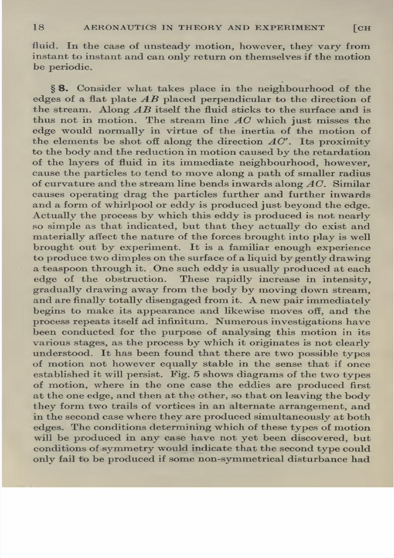
§ 8. Consider what takes place in the neighbourhood of the
edges of a flat plate AB placed perpendicular to the direction of
the stream. Along AB itself the fluid sticks to the surface and is
thus not in motion. The stream line AC which just misses the
edge would normally in virtue of the inertia of the motion of
the elements be shot off along the direction AC. Its proximity
to the body and the reduction in motion caused by the retardation
of the layers of fluid in its immediate neighbourhood, however,
cause the particles to tend to move along a path of smaller radius
of curvature and the stream line bends inwards along AC. Similar
causes operating drag the particles further and further inwards
and a form of whirlpool or eddy is produced just beyond the edge.
Actually the process by which this eddy is produced is not nearly
so simple as that indicated, but that they actually do exist and
materially affect the nature of the forces brought into play is well
brought out by experiment. It is a familiar enough experience
to produce two dimples on the surface of a liquid by gently drawing
a teaspoon through it. One such eddy is usually produced at each
edge of the obstruction. These rapidly increase in intensity,
gradually drawing away from the body by moving down stream,
and are finally totally disengaged from it. A new pair immediately
begins to make its appearance and likewise moves off, and the
process repeats itself ad infinitum. Numerous investigations have
been conducted for the purpose of analysing this motion in its
various stages, as the process by which it originates is not clearly
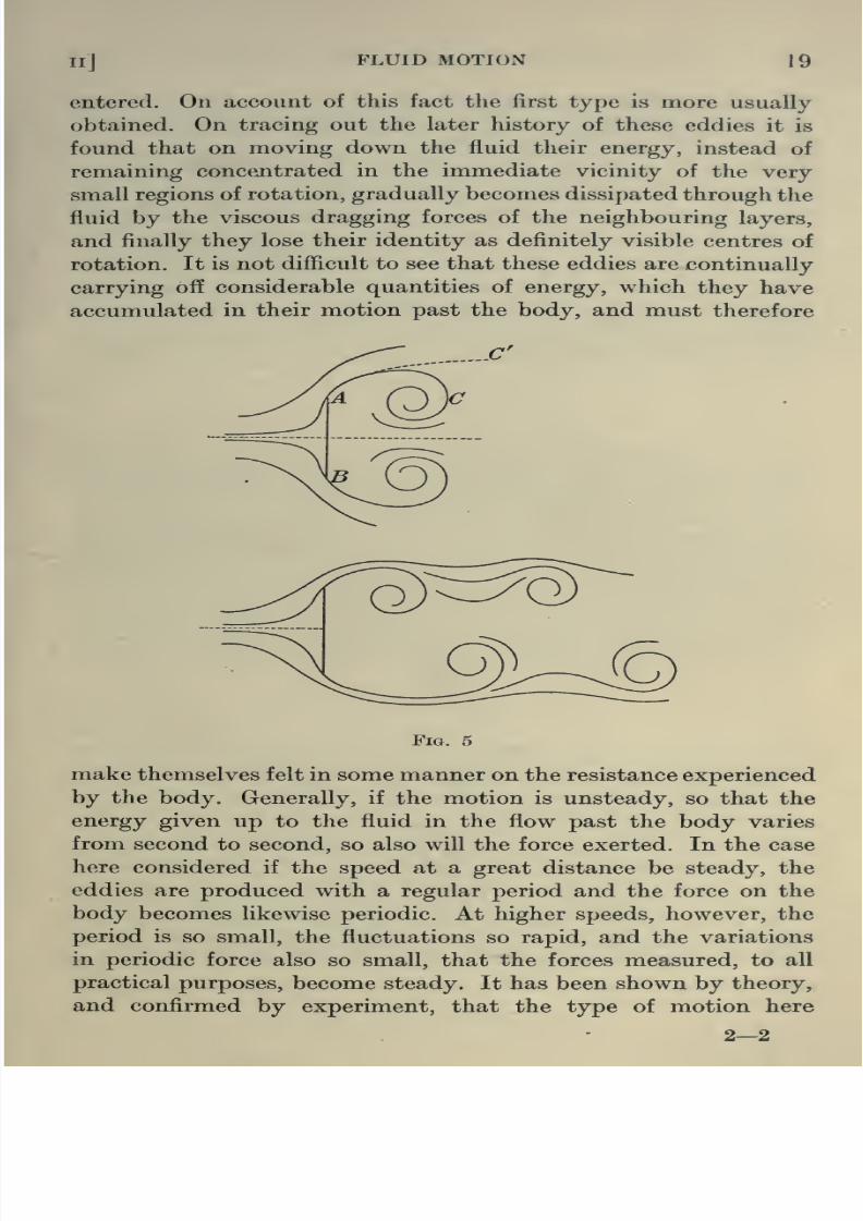
understood. It has been found that there are two possible types
of motion not however equally stable in the sense that if once
established it will persist. Fig. 5 shows diagrams of the two types
of motion, where in the one case the eddies are produced first
at the one edge, and then at the other, so that on leaving the body
they form two trails of vortices in an alternate arrangement, and
8/13/2019 Aeronautics in the 00 Cow Lu of t
http://slidepdf.com/reader/full/aeronautics-in-the-00-cow-lu-of-t 35/365
Ilj FLUID MOTION 19
entered. On account of this fact the first type is more usually
obtained. On tracing out the later history of these eddies it is
found that on moving down the fluid their energy, instead of
remaining concentrated in the immediate vicinity of the very
small regions of rotation, gradually becomes dissipated through the
fluid by the viscous dragging forces of the neighbouring layers,
and finally they lose their identity as definitely visible centres of
rotation. It is not difficult to see that these eddies are continually
carrying off considerable quantities of energy, which they have
accumulated in their motion past the body, and must therefore
Fig. 5
make themselves felt in some manner on the resistance experienced
by the body. Generally, if the motion is unsteady, so that the
energy given up to the fluid in the flow past the body varies
from second to second, so also will the force exerted. In the case
here considered if the speed at a great distance be steady, the
eddies are produced with a regular period and the force on the

8/13/2019 Aeronautics in the 00 Cow Lu of t
http://slidepdf.com/reader/full/aeronautics-in-the-00-cow-lu-of-t 36/365
20 AERONAUTICS IN THEORY AND EXPERIMENT [CH
discussed does not come into being for a plane of given size until
the velocity of the fluid at a considerable distance ahead of the
body attains a certain magnitude. At lower speeds than this,
eddies are apparently not produced. Curiously enough if the
dimensions of the plate be doubled the flow changes from the
steady type to the unsteady type at a speed of half the original
value. It is found in fact, that for a body of given shape there
exists a definite value oiv x I where v is the velocity of the stream
far ahead of the body, and I some fixed dimension of the body,
say its breadth, at which the flow changes from the steady to the
unsteady state. This is known as the critical value of vl. There
is an extension of this conception which states that for two bodies
of the same shape successive pictures of the flow past them are
identical for the same value of vl. This is a particular case of the
law of dynamical similarity which will be discussed in Chapter IV.
It is not merely when a sharp edge exists on a body thateddies are produced in a fluid. Any body in fact, if the value of
vl be great enough, will set up trails of eddies beyond it, but the
rate at which these are produced and their intensity and con-
sequently also the rate at which they carry off energy will depend
on the exact shape of the body.
Experimentally it has been shown that attempts to alter the
shape by smoothing out sharp corners, or indeed any rapid change
in curvature, result in the production of a state of flow in which
the eddying region becomes narrowed down to a comparatively
thin trail behind, with the intensity of the eddying and turbulence
in that region considerably diminished (cf. figs. 6 and 7*, 16 a
and 16 6). In addition to the effect of the removal of these rapid
changes in curvature, it is found that an alteration in the length
and shape of the hindmost part of the body frequently results in
a steadying of the motion. If the body is short the fluid is capable
of flowing at once in the form of an eddy immediately behind it,
whereas, if the tail is long so that some considerable distance
must be passed before an eddy can form properly, the whole nature
of the flow becomes considerably steadied and less energy is

8/13/2019 Aeronautics in the 00 Cow Lu of t
http://slidepdf.com/reader/full/aeronautics-in-the-00-cow-lu-of-t 37/365
FLUID FLOW PAST STRUTS
De Havilland (reversed)
Fig. 6
Beta
Fig. 7

8/13/2019 Aeronautics in the 00 Cow Lu of t
http://slidepdf.com/reader/full/aeronautics-in-the-00-cow-lu-of-t 38/365

8/13/2019 Aeronautics in the 00 Cow Lu of t
http://slidepdf.com/reader/full/aeronautics-in-the-00-cow-lu-of-t 39/365
II] FLUID MOTION 21
can be obtained by the presence of a blunted nose and a sharp
tail. Figs. 6, 7 and 8* show photographs of the types of motion
past a series of struts where the effect of the tapering tail and thesmooth contour of the surface is easily traced in the narrowness
of the region of turbulence behind. Such bodies are extremely
sensitive to slight variations in shape, a small discrepancy from
the good stream line form acting continually as a source of
disturbance to the smoothness of the flow, and consequently
dissipating energy. Experiments conducted in the wind channels
at the National Physical Laboratory have shown that the best
shape of struts designed to give low resistance have approximately
a fineness ratio of 3 : 1 or 4 : 1, the fineness ratio being the ratio
of the length of the cross section to the maximum thickness. The
foregoing remarks apply with equal force to the determination
of the best shape of the envelope of a dirigible, and in fact to
the determination of the contour of any surface in contact with
the air in its flight, among which may be mentioned aeroplane
bodies and wires.
§ 9. In practice, it is usually difficult to set up the struts of
an aeroplane accurately along the direction of flight, and as such
bodies are frequently very sensitive to changes in angle of yaw,
i.e. horizontal deviation from the direction of flight, the resistance
might increase rapidly under such conditions. It is consequently
regarded as desirable to select as the criterion for a suitable strut,
not that the axial resistance is a minimum among a set, but that
it is small and does not vary rapidly with angle of yaw. This latter
remark applies with special force to the case of aeroplane wires.
Fig. 9 shows the results of tests for a set of different wires where the
resistancecoefficient (i.e.
theresistance in lbs. per foot length
divided by plv^, where p is the density of the air, P- the area of
cross section in sq. ft. and v the speed of the wind in ft./sec.) is
plotted against angle of yaw. Wire A whose resistance is low, and
variation over a large range of angle of yaw small, is evidently
much more suitable than the others for that purpose. Apart from
this, this wire possesses the special advantage of ease of manu-

8/13/2019 Aeronautics in the 00 Cow Lu of t
http://slidepdf.com/reader/full/aeronautics-in-the-00-cow-lu-of-t 40/365
(A)
(B)
\\ /a>^
C;
lA
^ ^^1
Ayi AY 1
^iV. J1 A

8/13/2019 Aeronautics in the 00 Cow Lu of t
http://slidepdf.com/reader/full/aeronautics-in-the-00-cow-lu-of-t 41/365
FLOW PAST FLAT PLATES
9°
10'
15'

8/13/2019 Aeronautics in the 00 Cow Lu of t
http://slidepdf.com/reader/full/aeronautics-in-the-00-cow-lu-of-t 42/365
FLOW PAST FLAT PLATES
20°
25'
8/13/2019 Aeronautics in the 00 Cow Lu of t
http://slidepdf.com/reader/full/aeronautics-in-the-00-cow-lu-of-t 43/365
CH II] FLUID MOTION 23
the air flow in the neighbourhood of a strut. It has been found
that for certain bodies of strut form situated in a wind of given
speed, the resistance experienced, although approximately pro-
portional to the square of the speed, is not unique but may have
two or even three distinct values. By adequate control of the
experimental conditions, as for example by raising or by decreasing
the wind speed from a lower or from a higher value, to that
required for the test, any one of these resistances may be obtained
at the discretion of the experimenter. In view of the fact that the
resistance experienced depends purely on the nature of the air
flow, this result would seem to suggest that with given wind speed
and shape of body the type of flow is not uniquely determined,
but that the nature of the disturbance or previous history of the
air exerts some selective effect.
The problem is too complicated to enter into here, it is not
in fact clearly understood, but its solution evidently involving
the question of the stability of fluid motion would throw a very
strong light upon the general elucidation of aerodynamic pheno-
mena.
§ 11. From the point of view of experiment, the aerofoil
presents one of the more complicated problems in aerodynamics.
Thepossible
variationin
shape, attitude to the wind, speed,etc.,
are so numerous that an elaborate series of investigations is
necessary before accurate knowledge of the conditions governing
the forces brought into play can be derived. It is to experimental
work in the wind channel that one must turn for an accumulation
of knowledge, regarding the magnitude of the forces, but on
account of the invisibility of the air, experiments in a water
channel are much more suitable as a means of discovering the laws
of the fluid upon which the production of these forces is based.
Experiments on flat plates in a uniform stream show the existence
of two trails of eddies or vortices, one starting off from each edge
(see figs. 10 and 11). If instead of a flat plate an aerofoil or indeed
any curved surface be placed in the stream at a comparatively
low angle of incidence, the eddying region becomes considerably

8/13/2019 Aeronautics in the 00 Cow Lu of t
http://slidepdf.com/reader/full/aeronautics-in-the-00-cow-lu-of-t 44/365
24 AERONAUTICS IN THEORY AND EXPERIMENT [CH
It is to the vertical force exerted by the fluid on the aerofoil, that
one must look for providing the means of support to the machine,
and fortunately the cambering of the wings not merely diminishes
the resistance under certain circumstances, but increases the
lifting force by incHning the resultant upwards.
Experiments which will shortly be described on the pressure
at each point of such a surface indicate, as shown in fig. 12, that,
on the under surface, the pressure is everywhere positive, this
region extending round the nose to a point on the upper surface
a short distance in front of the maximum ordinate. From there
onwards along the upper surface the pressure is negative, that is
to say less than the atmospheric pressure. The maximum positive
pressure, found experimentally in all cases to be Ipv'^, occurs just
at the nose while the maximum negative pressure occurs just
before the maximum ordinate a. This pressure, experimentally
measured, is the component perpendicular to the surface at the
point. The upper surface accordingly contributes towards the lift
Fig. 12
by a suctional effect, while the under surface by a direct positive
pressure. A comparison between the magnitudes of these pressures
shows however that the former is of considerably greater con-
sequence in this respect than the latter, and since the maximum
negative pressure occurs at a position of the surface almost
horizontal it is clear that the position and magnitude of the
maximum ordinate will be a factor of extreme importance in
deciding the performance of an aerofoil. Experimental work
showing the modifications produced in the actual flow by changes
in shape has not been carried sufficiently far to justify conclusions
being based upon it, but interesting information is forthcoming
of the changes in the flow caused

8/13/2019 Aeronautics in the 00 Cow Lu of t
http://slidepdf.com/reader/full/aeronautics-in-the-00-cow-lu-of-t 45/365
FLOW PAST AEROFOILS

8/13/2019 Aeronautics in the 00 Cow Lu of t
http://slidepdf.com/reader/full/aeronautics-in-the-00-cow-lu-of-t 46/365
FLOW PAST AEROFOILS
10 ^
14'

8/13/2019 Aeronautics in the 00 Cow Lu of t
http://slidepdf.com/reader/full/aeronautics-in-the-00-cow-lu-of-t 47/365
FLOW PAST AEROFOILS
16°
20°

8/13/2019 Aeronautics in the 00 Cow Lu of t
http://slidepdf.com/reader/full/aeronautics-in-the-00-cow-lu-of-t 48/365
Flow past circular cylinder
Fig. 16 a
Flow past flat plate
Fig. 16 6

8/13/2019 Aeronautics in the 00 Cow Lu of t
http://slidepdf.com/reader/full/aeronautics-in-the-00-cow-lu-of-t 49/365
Jl] FLUID MOTION 25
from one of comparatively uniform eddying motion to a violent
turbulence. What is in effect taking place will be understood
when it is realised that for each body of given shape there existsone or more critical velocities, in the widest sense of the term,
at which the nature of the motion undergoes a rapid alteration,
a phenomenon already found to exist in the case of struts. The
same aerofoil, by an alteration of attitude to the stream, is in
reality equivalent to a body of different shape in relation to the
stream, and a continuous alteration in angle of incidence appears
thus as a continuous variation in shape of body, until finally an
angle of incidence is reached at which the shape of body thus
presented to the stream possesses that velocity as its critical.
The word is here used in the sense that in the region of that speed
the nature of the flow clearly undergoes a rapid change of type.
The change is not of course quite sudden but it is comparatively
sharp. The real cause of this rapid transition will not naturally
be clearly understood until considerably more progress has been
made in the theory of fluid motion, but the fact of its occurrence
is of vital consequence for a thoroughly reliable anticipation
of the performance of an aerofoil. The effect of this so-called
burble point not unnaturally becomes apparent when the
measurement of the forces brought into play on an aerofoil are
undertaken in the wind channel. At the burble point the lifting
force drops sharply and just as quickly rises again. Accurate water
• channel work of this nature could be a valuable asset to a clear
comprehension of innumerable problems that present themselves
in aeronautics, but the subject is unfortunately still in its infancy,
and no sound and complete analysis of even the simplest case of
the flow of a viscous fluid has yet been produced.
§ 12. Keference has been made to the distribution of pressure
over the surface of an aerofoil when situated in a steady current
of air. When a body is immersed in a fluid at rest, the pressure
at any point is perpendicular to the surface, but this is not the
case when the fluid is in motion except in the ideal perfect fluid

8/13/2019 Aeronautics in the 00 Cow Lu of t
http://slidepdf.com/reader/full/aeronautics-in-the-00-cow-lu-of-t 50/365
26 AERONAUTICS IN THEORY AND EXPERIMENT [CH
be perpendicular to the surface, but must be inclined to it. For
purposes of measurement the pressure is usually transmitted from
a pinhole through the surface, by means of a tube in the interior
of the body to a form of manometer outside to be described
shortly. Now it is clear that this method will only determine the
component of the pressure at the point normal to the surface,
and cannot measure the tangential or skin frictional com-
ponent. The difference between the actual force on a body as
measured in the wind channel and that obtained by integration
of the normal pressures will thus provide an estimate of the value
of the skin friction. Experiments conducted with the express
purpose of determining the magnitude of this effect by Zahm and
others have indicated that it is roughly proportional to the product
of the area of surface exposed, and the velocity raised to the power
1-89. Kemembering that the fluid in im-
mediate contact with the body is at relative
rest so that very small grooves in the surface
are filled up, it is not unexpected to find
that the skin frictional resistance is not
appreciably affected by roughness of sur-^^^' ^^
face. The direction of each component of this resistance will of
course be in the direction of the relative motion of the fluid
near the surface layer, and thus in general contributes towards
an increase in resistance, as at ^4, but in certain cases of struts, as
for example where the eddying causes a relative motion near parts
of the surface in opposite direction to that of the general fluid,
as at B, the skin friction may actually contribute towards a
diminution in resistance. (See fig. 17.)
The foregoing remarks on skin friction are typical of the light
thrown upon the problem of resistance by a discussion of the
pressure distribution over the surface of the body. A considerable
amount of experimental work of this nature has been carried out
at the National Physical Laboratory and much useful information
obtained. In fig. 18 the variation in pressure over the surface of
a model of a Parseval is shown. The pressure at the fore-part

8/13/2019 Aeronautics in the 00 Cow Lu of t
http://slidepdf.com/reader/full/aeronautics-in-the-00-cow-lu-of-t 51/365
II] FLUID MOTION 27
immediately clear from an analysis of this curve. From ^ to J5
he pressure is positive and provides a direct resistance. From
C to D the pressure is also -fi
positive, and since the in- , J\ I
clination of the surface is of I V< —->^^,^^ i
opposite sign to that at AB ^Y \ ^r:>^-T>
this tends to push the body V^^^.-^i::^^^^---'^^^^^
forward and diminish the--—--
resistance. Along BC where ^^®- ^^
the inclination of the surface is small the pressure scarcely
affects the resistance at all. The advantage of having a long
tail is at once apparent.
§ 13. In all cases where an investigation of the pressure
distribution has been carried through it has been found, as already
mentioned, that the maximum positive pressure alwaysoccurs
at some point situated on the fore-part of the body, the value
being always \pv^ where p is the density of the air and v the
velocity. If this point were regarded as the position at which a
stream line meets the body and comes to an end upon it, it can
be shown theoretically that if the fluid be further supposed devoid
of viscosity, the pressure at that point must reach this same
value. For a proof of this the student is referred to the next
chapter.
The fact that the pressure at a point of a body meeting the
air full on is \pv^ has been utilised for devising an instrument to
measure wind speed, known as the Pitot Tube. The general
^—outline is given in fig. 19. It is comprised of two hollow tubes
^fitting one inside the other, and closed along the circular edge ah.
The outer tube is perforated at the points C, D, £ , etc., and open
again at the outside at F. The inner tube is open both at the
Upfront ah and at the end G. The fore-part ZF is placed parallel
to the wind W whose speed it is required to measure. The pressure
across the section ah in the inner tube is then the ordinary dynamic
pressure already mentioned Jpv^ added to the general atmospheric

8/13/2019 Aeronautics in the 00 Cow Lu of t
http://slidepdf.com/reader/full/aeronautics-in-the-00-cow-lu-of-t 52/365
28 AERONAUTICS IN THEORY AND EXPERIMENT [CH
pressure Pq. This pressure is transmitted through F to the other
arm of the U tube. The weight of the column of liquid per unit
area between the two levels of the fluid in the U tube
and from a measurement of this difference in level the velocity
can evidently be calculated. The verification of the assumption
that the dynamic pressure at the nozzle is ^pv^ is usually effected
by fixing the pitot tube at the extreme end of a whirling arm,
consisting of a long horizontal beam capable of rotating ina
horizontal plane at a speed of known amount. The pitot is so
placed that the portion XY points along the direction of the
relative wind, and the pressures are then carried as before from
W
Fig. 19
each of the two projecting portions F and 6^ to a pressure gauge
as already explained. The difference in pressure thus measured
is shown to equal ^pv^. The pressures set up in the two connecting
tubes running along the arm to the gauge due to the centrifugal
force of rotation of the columns of air enclosed of course balance
each other when connected to the pressure gauge.
The pressure gauge, essentially of the U tube type, fig. 20
consists of two cups A and B to which the two tubes of the
pitot are connected. From the two cups there is one continuous
fluid system through the tubes CD, EF. The fluid in the two
cups is the same (brine 1-06 density), but the bulb enclosing the

8/13/2019 Aeronautics in the 00 Cow Lu of t
http://slidepdf.com/reader/full/aeronautics-in-the-00-cow-lu-of-t 53/365
n] FLUID MOTION 29
pressures in these cups. When the gauge is connected to the
pitot, the air pressure in B being different from that in A, the
position of the meniscus will accordingly alter, but by raising
the one cup relative to the other so that the level of the fluid in
the one is higher than that in the other, this extra pressure may
be compensated for, until the bubble returns to its original
position. The amount by which the one cup requires to be raised
above the other will clearly give a measure of the difference of
pressures in^ and B. This raising or tilting is effected and
measured by means of the horizontal wheel W and micrometer
screw S. The amount of tilt, and consequently the difference in
pressure, is measured on the scale at T. This type of gauge on
which pressures down to 1/1000 in. of water may be measured
was originally due to Prof. Chattock, and is in general use at the
National Physical Laboratory.
Brine
Fm. 20
§ 14. It is by means of this type of gauge and the pitot
tube already described that the calibration of the wind channels
used for aerodynamical work is effected. The wind speed is
determined by means of the pitot, and at the same time for
each speed the corresponding pressure at a small hole in the side
of the channel is measured by transmission to a pressure gauge.
Once this calibration has been effected it is evidently possible
at any future time to determine the speed of the wind in the
channel from a measurement of the pressure at the side, and this

8/13/2019 Aeronautics in the 00 Cow Lu of t
http://slidepdf.com/reader/full/aeronautics-in-the-00-cow-lu-of-t 54/365
30 AERONAUTICS IN THEORY AND EXPERIMENT [CH
verified, that this simple law breaks down at velocities approaching
that of the speed of sound waves. It has so far been assumed
that the pressures brought into being by the motion are not ofsufficient magnitude to introduce changes in the nature of the flow
due to the compressibility of the medium. Analysis of the flight
of projectiles indicates however that under such circumstances
this condition is violated, and along that path of the trajectory
at which the velocity is in the neighbourhood of or beyond that
of sound waves in air the resistance increases at a much higher rate
than on the remainder of the flight path. The method of deter-
mining this is extremely simple. The position of the shell at
-v/v
Fig. 21
various times along its path is noted from the times of bursting
of a series similarly projected. If s be the distance measured along
the path, the experiment furnishes a curve showing the variation
of this quantity with time. By differentiating twice the decelera-
tion of the shell is found and by adding to this the component
due to gravity at each point the resistance, and hence the
resistance coefficient, is derived. Plot-
ting this against v\Y, where v = speed
of shell and F = speed of sound, a
curve of the type shown in fig. 21 is
obtained.
From an examination of this curve
the remarkable result becomes ap-

8/13/2019 Aeronautics in the 00 Cow Lu of t
http://slidepdf.com/reader/full/aeronautics-in-the-00-cow-lu-of-t 55/365
II] FLUID MOTION 31
vjV = 1, the resistance increases very rapidly and extra energy,
apart from that expended in overcoming the viscous forces, is
dissipated by the formation of sound waves. The shell is riding
on the crest of the compression waves it produces. Beyond this
region, where the projectile penetrates into the medium more
rapidly than the waves it forms, the resistance coefficient once
more settles down to a constant value, in magnitude however
considerably greater than previously. Fig. 22 illustrates a
photograph that has been obtained by Prof. C. V. Boys, showing
the actual sound waves produced by the motion of a bullet.
§ 16. The exact nature of the stream lines, the rate at which
eddies are being produced and the rate at which energy is being
dissipated in the form of sound waves, if such occur, all contribute
towards the production of what is ultimately experienced as
resistance. It follows that in general there exists a unique relation
between the magnitude of this resistance and the nature of the
flow. It is equally clear that if a body be moving in a viscous
fluid with velocity v the nature of the flow and the stream lines
which it originates will not necessarily be identical with that
occurring when the same body is passing through the velocity
V under an acceleration. The fluid which it leaves behind in the
latter case will be disturbed in a totally different manner from that
in the former. It might be anticipated in the light of these
remarks that the resistance of an accelerated body whose velocity
at any instant is v will differ from that of the same body when
moving constantly with velocity v. It has, however, been found
experimentally that the magnitude of the difference is of the order
of the weight of the fluid displaced by the body and consequently
for that branch of aeronautics which deals with aeroplanes, the
resistance may be taken as independent of the acceleration and
merely a function of the velocity. In the case of larger bodies,
however, such as airships, where evidently the weight of the mass
of air displaced is of the same order as the total weight of the air-
ship, this difference attains considerable importance and is usually
allowed for by assuming that the mass of the airship receives

8/13/2019 Aeronautics in the 00 Cow Lu of t
http://slidepdf.com/reader/full/aeronautics-in-the-00-cow-lu-of-t 56/365
32 AERONAUTICS IN THEORY AND EXPERIMENT [CH
the flow past such comparatively simple shaped bodies as struts
and aerofoils. This being so it will readily be appreciated, that a
clear investigation of the case of a rotating propeller movingforward through the fluid will practically be beyond our powers
at the present stage, both experimentally and theoretically.
Viewed very generally it will be possible to state that the air in
front will be sucked in and discharged behind in a converging
stream within which the motion will be a complicated combination
of translational, rotational and eddying energy. As far as possible
a more exact investigation of this extremely intricate problem
will be reserved for Chapter IX.
§ 18. Atmospheric Conditions. It has been tacitly understood
that the fluid with whose properties we have been concerned has
been continuously preserved at constant temperature. It requires
veryslight consideration to see that
hadthis condition
beenviolated to any appreciable extent, the nature of the resultant flow
would have been considerably modified. From Charles' and Gay-
Lussac's law which states that PV = RT, P, V and T being the
pressure, volume and temperature absolute of any portion of the
fluid, and R a constant for constant mass, a variation in T in
general affects the pressure and thus disturbs the motion of the
fluid.
Under atmospheric conditions the temperature is never
uniform but falls off rapidly from the surface of the earth upwards.
Each part of the earth is more or less continually being heated
up daily for many hours under the effect of the sun's rays and
during the remaining time is screened. As a consequence of this
diurnal variation in temperature a variation in pressure is set up
in the immediate belt surrounding the earth and convection of air
tends to take place from regions of higher temperature to those of
lower. This general effect is however considerably modified by
local conditions. The form of contour of the earth's surface
obstructs the flow and originates eddying motion of various forms.
Extremely localised changes in temperature due among other

8/13/2019 Aeronautics in the 00 Cow Lu of t
http://slidepdf.com/reader/full/aeronautics-in-the-00-cow-lu-of-t 57/365
Ill FLUID MOTION 33
spin of the earth, so that instead of moving directly it circulates
round the position of lower pressure, giving rise to so-called
cyclonic conditions, or when the circulation is about regions of
high pressure, so-called anti-cyclonic weather. For many aero-
nautical purposes of primary importance, both experimental and
military, an accurate study of weather conditions, the general
laws governing them and the particular and local conditions
affecting them is essential. Air raids for an example, and this is
especially important with airships, can only be executed when it
is known generally that the prevailing type of weather will be
favourable. Variations of temperature and pressure with height
interfere with the efficient working of the engine. Winds and gusts,
both horizontal and directed partially or wholly upwards or
downwards, materially modify the aerodynamic performance of
machines, and without a clear understanding of the origin of these
disturbances reliable experimental work and accurate tests on
complete aeroplanes cannot be carried out.
The general variation of temperature, pressure and density
with height above the earth's surface is given in the following
tables, in which is included also the dependence of viscosity on
temperature.
Values ofp and v.
I slugs, L in feet, T in seconds. Slug= mass of g
p air
p water
V air
= 0-00237 at 15° C. and 760 mm. Hg= 1-94 or 815 times that of air
= 0-000144 at 0° C. and 760 mm. Hg= 0-000159 at 15° C.
= 0-000251 at 100° C.
V water = 0-0000164 at 5°= 0-0000159 „ 6°
= 0-0000154 „ 7°
= 0-0000150 „ 8°
= 0-0000146 „ 9°
= 0-0000141 „ 10°
=0-0000137 „ 11°
= 0-0000134 „ 12°
= 0-0000123 „ 15°
=0-0000108 „ 20°
Units
LyT

8/13/2019 Aeronautics in the 00 Cow Lu of t
http://slidepdf.com/reader/full/aeronautics-in-the-00-cow-lu-of-t 58/365
34 AERONAUTICS IN THEORY AND EXPERIMENT [CH II
Variation of Pressure, Temperature, and Density of the
Atmosphere ivith Height,
i
Density Density
Height
ft.
Pressure Temp.
Cent.
Temp.
Cent.
Pressure
Ins. 1 lbs. 1 lbs. Ins.
Hg Abs. g'{it:f Ratio g'(it.f Ratio Abs. Hg
300 2821
0-00246 1-000 000237 1-000 279 29-00
2,000 28-1 280 0-00232 0-940 0-00224 0-940 277 26-90
4,000 26-2 278 0-00215 1 0-875 0-00208 0-880 274 24-956,000 24-4 277 000201 0-815 0-00196 0-825 271 23-15
8,000 22-65 275 0-00187 0-760 0-00185 0-780 267 21-35
10,000 20-9 272 000175 0-710 0-00172 0-725 263 19-75
12,000 19-35 269 000163 0-665 0-00163 0-685 2.59 18-20
14,000 17-9 266 0-00153 0-625 0-00151 0-635 253 16-75
16,000 16-55 263 000144 0-585 0-00142 0-600 249 15-45
18,000 15-25 258 000133 0-540 0-00134 0-565 244 14-25
20,000 14-05 254 0-00125 0-510 0-00126 0-530 240 13-10
22,000 12-95 249 0-00118 0-480 0-00118 0-495 235 11-95
24,000 1200 245 0-00108 0-440 0-00109 0-460 230 10-95

8/13/2019 Aeronautics in the 00 Cow Lu of t
http://slidepdf.com/reader/full/aeronautics-in-the-00-cow-lu-of-t 59/365
CHAPTER HI
MATHEMATICAL THEORY OF FLUID MOTION
Introduction
§ 1 . In the previous chapter the nature of the flow of a viscous
fluid under various conditions was discussed qualitatively from
comparatively elementary considerations, and incidentally the
distinction between a viscous fluid and the perfect fluid usually
dealt with in mathematical theory was clearly indicated*. In
the latter case it was explained that when the fluid was under
the action of tangential forces not merely could it not withstand
them permanently, as indeed is the essence of any fluid, but no
internal forces of frictional nature are brought into play to resist
the change. In actual reality there can be no such thing as a
perfect fluid according to this conception, yet the theory of its
motion that has been developed, and the laws that govern it,
frequently serve as a useful guide in the theory of aeronautics.
On account of the difficulties inherent in a complete quantitative
discussion of the behaviour of a viscous fluid, very little progress
has been made by mathematical physicists in that direction, but
on the other hand, mathematical treatment of the perfect fluid
has yielded considerably to analysis. The nature of the flow
will in general differ widely from that of an actual fluid, but
under certain circumstances, especially during so-called stream
line flow, a certain amount of useful information is forthcoming.
§ 2. Two-dimensional Flow. Fortunately for the analyst most

8/13/2019 Aeronautics in the 00 Cow Lu of t
http://slidepdf.com/reader/full/aeronautics-in-the-00-cow-lu-of-t 60/365
36 AERONAUTICS IN THEORY AND EXPERIMENT [CH
to their cross-section that the fact that they possess ends at all
does not appreciably affect the nature of the motion of the fluid
past them except in the immediate neighbourhood of these ends.
In such an event, if the body be of uniform cross-section, fluid
which before entering the region of the strut or aerofoil flowed
in the plane XOY, perpendicular to the length, will not be
deflected out of that plane, and the motion will remain two-
dimensional. It will be seen that the generality of the conclusions
arrived at will scarcely be affected at all by this assumption, and
at the same time a considerable saving in mathematical labour
will evidently be involved.
A large amount of experimental evidence has been accumulated
during the progress of aeronautical research indicating that up to
speeds approaching the velocity of sound, the pressures brought
into existence by motion through the air are such as would arise
were that medium acting as though it were incompressible. It is
Xjc o
Fig. 23
not until energy is dissipated in the form of sound waves that the
elasticity of the air affects the question to any degree, and since
normal aeronautical speeds do not approach anywhere within
that critical region there can be no error involved in assuming
that the density of the fluid to be discussed in this chapter
remains constant. It is only in the supposition that viscous forces
do not exist that conclusions derived for the ideal fluid can fail
in their application to reality.
§ 3. Derivation of the Equations of Motion. The equations
determining the motion must be derived by a mathematical
statement of the two basic facts of the nature of the fluid:

8/13/2019 Aeronautics in the 00 Cow Lu of t
http://slidepdf.com/reader/full/aeronautics-in-the-00-cow-lu-of-t 61/365
B
bx
du .
dx
D
III] MATHEMATICAL THEORY OF FLUID MOTION 37
In a sense these two statements and all that they involve
are a definition of the nature of the fluid, and all deductions
regarding its behaviour can 5^
only be a recasting of these y. dy ^
into a new but equivalent ^ |
form. Consider a small rect- u,
angular slab of the fluid
ABCD such that DC = 8x
and CB=hy, and suppose 0^ —^xu and V to be the velocity ^cj- 24
components horizontally and vertically at the mid-points of DAand DC respectively, then the corresponding components at the
mid-points of AB and CB are v-\- ^hy and w + ^ Sa? re-
spectively, since u and v are increasing in their corresponding
directions at rates >r- and >.- .
ox oy
The quantity of fluid entering the small element ABCD in
the horizontal direction is accordingly puhy and that leaving
p ( w + ^- Sicj Siy, where p is the density of the fluid.
In the same way the amount entering in the y direction is
pvhx and that leaving plv + ^-hy\hx.
Statement (1) demands that the total quantity of fluid
within ABCD must not increase, and accordingly it follows that
puhy — p f w + p- 8x\ 8y + pv8x— p [v + ^ 8y\ Sx= 0,
and hence t^-
+ ^= (1).
dx dy
This is the equation of continuity of mass and is the mathematical
equivalent to statement (1).
For an interpretation of statement (2) the forces which are
acting upon the small element ABCD producing the motion must
be analysed.

8/13/2019 Aeronautics in the 00 Cow Lu of t
http://slidepdf.com/reader/full/aeronautics-in-the-00-cow-lu-of-t 62/365
38 AERONAUTICS IN THEORY AND EXPERIME^JT [CH
(6) The pressure due to the surrounding fluid on the element
ABCD.
If
pbe
the pressure at the ymid-point DA, then
will be the back pressure at the
mid-point of CB and the total
resultant thrust in the direction ^
OX on the element then becomes
A B
P-^bx
^..|«.
D C
Fig. 25
dp dp
Newton's Second Law applied to the element in the direction
OX then takes the form
pXSxSy —^ SxSy
=p Sx hy X (acceleration of element ABCD in direction OX).
Now the velocity at any point in the fluid will depend not merely
on the geometrical coordinates of the point but also on time.
Even at a fixed point in the medium the velocity will vary from
second to second and therefore u and v are functions of x, y and t.
Hence
' du _du dx du dy du dt du . du
'Jt~ dxdt^ dy dt'^ Tt
and this is the expression for the acceleration in the horizontal
direction. The equation of motion thus becomes
du
dx dy dt'
pXSxSy-^SxSy
or X- 1 a^
p dx
= P
du
Sx8y I
du du
dt dx
du\
du du^
dt dx dyj(2).
By exactly the same process from a consideration of the forces
in the direction OY we obtain

8/13/2019 Aeronautics in the 00 Cow Lu of t
http://slidepdf.com/reader/full/aeronautics-in-the-00-cow-lu-of-t 63/365
8/13/2019 Aeronautics in the 00 Cow Lu of t
http://slidepdf.com/reader/full/aeronautics-in-the-00-cow-lu-of-t 64/365
40 AERONAUTICS IN THEORY AND EXPERIMENT [CH
It will be found in text books on the Differential Calculus,
and it can be easily verified, that (4) is simply the condition that
a function ijj exists such that
« = -4' ' ax'^>-
In essence the two equations (7) are identical with (4) and no
limitation is thereby involved on the nature of the problem.
§ 5. Various aspects of the question are readily represented
in terms of this new function.
If q be the resultant velocity at any point in the fluid, then
'=•— ©-(2) <«idy
Since u and v are the component velocities, vju is the slope of the
direction of motion at the point, but
/ = _ ^/M'
dxj dy
— slope of the curve determined by = constant. That this is so
can be easily seen by differentiating j/r; thus//•Hv ) * u^
dx dy dx'
, dy _ dip jdifj
'
' dx dx/ dy'
The remarkable result follows at once that the series of curves
represented by^ _ constant
and obtained by giving a series of values to the constant are
simply the stream lines in the problem, since the direction of
motion coincides at every point with the direction of the curve
of this system that passes through the point.
The problem of the motion of a perfect fluid now reduces
itself to determining an expression as a function of x and y
satisfying the boundary and initial conditions, the component

8/13/2019 Aeronautics in the 00 Cow Lu of t
http://slidepdf.com/reader/full/aeronautics-in-the-00-cow-lu-of-t 65/365
Ill] MATHEMATICAL THEORY OF FLUID MOTION 41
By means of this new function the pressure equations (5) and
(6) can after a little manipulation be thrown into a much more
convenient form, viz. '
Idp a?/ du Id (du dv\
pdy 2dy^^^ ai/W aW*
Multiplying these equations by dx and dy respectively and adding,
remembering that
we obtain on integrating
r2 r
/aa^ a2,/r>
.(9).
If Pq be the pressure on the stream line ip^ , where the velocity is
qQ, then
^=?^%f#vv (10),
where ^^-^ =3+^ dD-
Equation (10) thus provides a means of determining the pressure
at any point in terms of the velocity at that point and the
function j/f for the system of stream lines when the motion is
steady and there are no external forces. If the motion be
unsteady

8/13/2019 Aeronautics in the 00 Cow Lu of t
http://slidepdf.com/reader/full/aeronautics-in-the-00-cow-lu-of-t 66/365
42 AERONAUTICS IN THEORY AND EXPERIMENT [cH
§ 6. It is clear that complications may arise in the evaluation
of the integral in (9) except when V^j/j can be expressed explicitly
in terms of ijj. It will be convenient to separate the problems that
arise into two classes, viz. those in which
{a) V^^O
and (6) V^=-^f{x,y).
To understand exactly the true nature of this classification it
will be necessary to enquire closely into the significance of theexpression V^j/f. Remembering that
dih ^ dih
u= — ~, and v= 7^ ,
dy ox
^ dx^ dy^ dx \ dxj dy \ dy,
_ dv du
dx dy'
Now the most general displacement of an element of a fluid
consists of a pure strain compounded with a rotation of angular
^'^l^^i*ylfdjv_du\
2 \dx dy)'
This is also well known in the elementary theory of elasticity.
The value that JV^«/f assumes at any point of the fluid then
represents the rotational velocity of the element of the fluid
situated there at the moment. It is frequently termed the sj>in
or rotation at the point. The significance may, however, be brought
out from another point of view.
§ 7. Flow and Circulation. If A and B be any two points in
a fluid the value of the integral
(udx + vdy)

8/13/2019 Aeronautics in the 00 Cow Lu of t
http://slidepdf.com/reader/full/aeronautics-in-the-00-cow-lu-of-t 67/365
ml MATHEMATICAL THEORY OF FLUID MOTION 43
Applying this to a small rectangular element of fluid ABCDof area Sx Sy,
dv
t + S5^^^
Fig. 26
the circulation round ABCD is
u8x-\- {v\ ox
^ )8x8y = ^V^SxSy.
du
dy
,dx dy)
From this point of view | V^j/r represents the circulation per unit
area or strength of circulation at the point in the fluid, while
from the earlier interpretation it appears as the intensity of spin
or rotation. Generally speaking therefore, the classification of the
problems that arise amounts simply to a separation into cases in
which there is no spin, or, as it will be referred to here, in which
there is irrotational motion of the fluid, and those in which spin
does exist and is distributed over the region of the fluid in a
manner determined by the expression/ (a;, y).
§ 8. Irrotational Motion.
.(12).dx'^ dy ^
Kewriting this in the form
dx \dxj dy \dyj'
and applying the same argument as was advanced when intro-

8/13/2019 Aeronautics in the 00 Cow Lu of t
http://slidepdf.com/reader/full/aeronautics-in-the-00-cow-lu-of-t 68/365
44 AERONAUTICS IN THEORY AND EXPERIMENT [CH
In the case of irrotational motion u and v can accordingly be
expressed in terms of a new function </> such that
dy dx'
dx dy'
- r-©v{»r=(i)V(grMoreover <^ satisfies the equation (12) since
a^^av^i¥_i^=o (U).
dx^ dy ^ dxdy dxdy
The geometrical interpretation of this new function and its
relation to the stream function is at once evident from the fact
that ^V _dy
u dc/)'
dx
which implies that the curves determined by </> = constant,
usually known as the equipotential lines, are the orthogonal
trajectories of the stream lines determined by = constant.
Since these two expressions moreover satisfy the same differential
equations (12) and (14) they are interchangeable as far as ex-
pressions for stream function of possible types of irrotational
motion are concerned. The system of stream lines and equi-
potentials divide the region of the fluid into a system of infinitely
small rectangles.
§ 9. Discussion of the equation
aa:^+V~ * '
The real key to the solution of any problem in the irrotational
motion of a non-viscous fluid lies in the determination of the
appropriate expression that satisfies this equation and at the
same time gives the requisite boundaries to the fluid. The pressure
will then be given by the modified form of (10), viz.

8/13/2019 Aeronautics in the 00 Cow Lu of t
http://slidepdf.com/reader/full/aeronautics-in-the-00-cow-lu-of-t 69/365
Ill] MATHEMATICAL THEORY OF FLUID MOTION 45
part of /(ic + iy), where i^= — 1. In fact, since cf) and ^ must
bothsatisfy this equation,
we maywrite
cf> + nl; = f(x + iy) (16).
That the equations (12), (13) and (14) are immediately derivable
from this becomes clear on differentiating, for
and equating real and imaginary parts equations (13) are shown
to hold. From these alone (12) and (14) both follow. It would
appear then that any number of problems of two-dimensional
irrotational flow and their solutions may be constructed by
simply choosing functions of the complex variable z= x -{- iy and
equating the real and imaginary parts to the potential and stream
functions </> and i/j respectively.
On the other hand, the determination of the particular function
of this nature to satisfy certain presupposed boundary conditions
is comparatively difficult to effect, and the method of solution has
frequently been the inverse one indicated above.
§ 10. Consider in illustration the case
<t>+ iilj^z+llz = x-hiy +^^
X — ill X ix ^ -\-y^
-\- 1) .w(a:2 + w2_l)= x + iy-v-^-—^= ^
„'^
.—' + 1^-^—2-r-^ '
x^ + y^ x^ -\- y^ x^ + y^
The stream lines are then given by
ip ^ y {x^ + .^2 _ iy(^x^ -f ^2^^
The particular stream line i/f = corresponds to
y =0 and x^ -\- y^— 1 =0,
i.e. the X-axis and the circle of radius unity may be taken as
fixed boundaries. The other stream lines are determined by
substituting a series of constant values for j/r. The final diagram

8/13/2019 Aeronautics in the 00 Cow Lu of t
http://slidepdf.com/reader/full/aeronautics-in-the-00-cow-lu-of-t 70/365
46 AERONAUTICS IN THEORY AND EXPERIMENT [CH
Hence at an infinite distance u= — 1, v = 0, and on the surface
of the body at x=^\,y-=Q,u=0,v=0, so that the circular
cylinder is stationary and the fluid is streaming past it with unit
velocity at infinity.
§11. The curves corresponding to ^ = constant, the ortho-
gonal trajectories to the stream lines, are indicated in the figure
by dotted lines and the systems(f>= constant and = constant
map out the field into an infinite number of infinitely small
rectangles. Each point in the fluid lying as it does at the point
of intersection of a curve of the one system with one of the other
will be associated with a particular value of (j> and ijj defining it in
general uniquely. We may in fact construct a new plane w,
of axes (j) and ijj, and each point in it will correspond to a point in
the fluid in the 2-plane. Each infinitely small rectangle in the
z-plane bounded by neighbouring stream lines and equipotential
Fig. 27
lines will correspond to an infinitely small rectangle in the i^-plane
bounded by lines parallel to the </> and j/f axes along which these
functions are constant. The relative dimensions of these corre-
sponding rectangles will depend of course on the exact relationship
between z and w, and a knowledge of these dimensions for the
whole region of the fluid would be equivalent to a solution of the
problem. It can be shown however that every functional relation-
ship of the type here known to exist, viz. w-= {z), demands that

8/13/2019 Aeronautics in the 00 Cow Lu of t
http://slidepdf.com/reader/full/aeronautics-in-the-00-cow-lu-of-t 71/365
Ill] MATHEMATICAL THEORY OF FLUID MOTION 47
giving such a correspondence between the z- and the w;-planes,
but the process is frequently facilitated by an intermediate step.
An attempt is made to transform the 2-plane and the w-plane
conformally on the upper half of a new ^plane so that both z
and w are expressed in terms of a new variable t, and these
together provide the functional relation between z and w required.
The fundamental theorem upon which most of these trans-
formations depends is due to Schwarz and Christoffel, who
succeeded in establishing the formula for transforming the region
bounded by a polygon conformally upon the upper half of another
plane. A large class of problems it will be seen ultimately depend
for their solution upon this step. It must be noticed that so long
as complex functions are dealt with, the hydrodynamical equations
will be satisfied and it will only be necessary therefore to consider
the boundaries. If a functional relation existing between two
planes is such as to provide a correspondence between the
boundaries in these planes it is the transformation required.
Consider the relation between the two complex variables z
and t^
| = ^((-(i) -'(«-'2F' (17).
where t^,t2^, ... are real quantities ranging from — oo to + oo and
a, ^, ... the internal angles of a polygon so that
a + p+ ... = (n-2)7T.
Consider the variation in the complex quantity
hz= ASt{t-tj)^~^it~t^)^-'^ ...
as t, always remaining real, moves cautiously along the real axis
in the ^plane from + oo to — oo . A may be either a real or
complex constant.
D C B A
Fig. 28
variable factors

8/13/2019 Aeronautics in the 00 Cow Lu of t
http://slidepdf.com/reader/full/aeronautics-in-the-00-cow-lu-of-t 72/365
a-izm
sAi^A
48 AERONAUTICS IN THEORY AND EXPERIMENT [CH
long as t lies between A and B, all the other variable factors will
remain unchanged in sign and real. The term
The first portion of this is now real and it is seen that the
effect of passing through i= t-^ has been to introduce into the
expression for hz a factor
(—l)7r~
= (cosTT — ^sin77)^~^= cos (tt — «) + i sin (tt — a).
Since the amplitude of the product of two complex numbers
is the sum of the amplitudes of the two constituents, this means
that the amplitude of hz after passing through the point A has
increased by 77 — a and from then
onwards maintains a constant ampli-
tude until it arrives at the point B.
The corresponding figure so far in the
2;-plane, fig. 29, clearly consists of the
two sides of a polygon inclined at
an angle tt — a. A similar effect is
produced in passing through B, G, ^^^- ^^
etc., and it becomes clear that the formula transforms the real
axis in the ^plane into the sides of a polygon in the 2-plane of
internal angles a, j8, etc. The expression for z derived by integra-
tion then provides the formula transforming the region bounded
by this polygon conformally on the upper half of the ^plane
where t is now supposed complex.
The foregoing verification of this theorem must not be taken
as a proof, and for a mathematically sound treatment the student
is referred to a text book on the Theory of Functions.
§ 13. As a simple appHcation of the method thus suggested
consider the problem where fluid, flowing horizontally at infinity
with velocity V, is supposed to impinge on a flat plate situated

8/13/2019 Aeronautics in the 00 Cow Lu of t
http://slidepdf.com/reader/full/aeronautics-in-the-00-cow-lu-of-t 73/365
MATHEMATICAL THEORY OF FLUID MOTION 49
Consider the relation between z and t that transforms this
jgion of the fluid bounded by the infinite polygon ABCDA'conformally to the upper half of a ^plane, where
A corresponds tot= oo,
B „ t=hC „ t=0,
D „ ^=-1,
A' „ t=- ao .
The internal angles of this polygon are
1 and t = — \,l^tt
27r at ^ = 0.
Hence from the Schwarz-ChristofEel Theorem
dzdt= A{t-l) ^t{t-\-\) ^ = At/Vit'' - I)
:.z=^AV(t^-l) + B.
Fig. 30
Let the origin in the 2;-plane be taken at B, so that for ^ = ± 1,
= and for ^ = 0, 2 = li, where 21 is the total breadth of the plane,
ienB= and A=- I.
:.z=W(t^-i).
^or the construction of the w-plane we notice that the fluid is
'^bounded by 0= and a stream line infinitely far away, i.e. j/f = 00,
so that the corresponding region is thus the upper half of the
w;-plane. This is clearly transformed to the corresponding upper

8/13/2019 Aeronautics in the 00 Cow Lu of t
http://slidepdf.com/reader/full/aeronautics-in-the-00-cow-lu-of-t 74/365
50 AERONAUTICS IN THEORY AND EXPERIMENT [CH
These two equations are the solution of the hydrodynamical
problem provided the constant C be determined, and this must
evidently depend on the conditions of the fluid at an infinite
distance where the fluid is supposed flowing steadily with velocity
F horizontally. Now
,7., ., dw dw dt r^Vit^ — I)
WhenI
^I
^ 00 this limits to C/l,
and accordingly w= IVt, z= I '\/{fi — 1),
or ^2 _ 12 (^2 _ 1) _ (^2 _ I2y2yy2^
or w^=V^{z^+l^).
A separation of the real and the imaginary terms then provides
as the expression for the system of stream lines
04 _|_ 72 (^2
-y2^ 12)02 _ 72^2^2
_ 0.
It may be remarked that from the symmetry of the solution
with regard to x and y the corresponding pressures on each side
of the plate are equal and oppositely directed and consequently
no resistance will be experienced. An examination of the velocity
at various points on the plate, viz.
^ = V^zjw = Vz/Viz^ + 1%
shows that it is zero at z= 0, i.e. the centre of the plate., and
infinite at 2 = ± i, i.e. at the edges C and C .
This illustration may be taken as typical of the species of
problem that may be solved by the direct application of the
Schwarz-Christoffel transformation to the z- and ?<;-planes, but it
is evident that its success will be seriously limited by the fact
that the boundaries must be plane sides of a polygon. There is,
however, an extension of the theorem to curved boundaries for
which the student must be referred to the original papers*.
Considerably greater freedom may be obtained if it be remarked
that the application need not be restricted to the 2;-plane but
to any other plane that may be derived from, it or from any
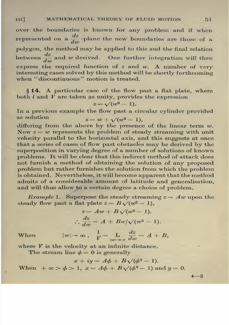
8/13/2019 Aeronautics in the 00 Cow Lu of t
http://slidepdf.com/reader/full/aeronautics-in-the-00-cow-lu-of-t 75/365

8/13/2019 Aeronautics in the 00 Cow Lu of t
http://slidepdf.com/reader/full/aeronautics-in-the-00-cow-lu-of-t 76/365
52 AERONAUTICS IN THEORY AND EXPERIMENT [CH
When 1 ></>>- 1,
x + iy^ A<f> + iB^/(l - cf>^),
:.x=A<t>, y=BV(l-cl>^),
x^ y^
an ellipse of semi-axes A and B.
When — 1 >(/>>— 00,
x + iy=Acl>-BV{cf>^- 1),
.-. x=A<l>-BV{cl>^-l), y=o.
The problem is thus that of the steady symmetrical flow of a
fluid past any elliptic cylinder of the seriesji + ^2 ^ -^ •
The student will find it an interesting exercise to discuss the
more general case where A and B are not restricted to be real.
Example 2. Superpose two cases of the steady flow past
a plate, e.g. z= A (w^- 1) + B {w^~ 4).
As before the velocity at an infinite distance is 1I(A + B) and
is horizontal, and the obstacle is the elliptic cylinder
A^ ^ £2 ^'
with a portion of the minor axis projecting beyond the surface
of the cylinder.
Resistance
§ 15. An examination of the system of stream lines repre-
senting the flow past a symmetrical body like a cylinder shows
that the pressures round the surface must balance, and con-
sequently the fluid exerts no resultant thrust on the body. That
this theorem is of general validity for the steady motion of any
body in a perfect fluid may be shown in a variety of ways. The
pressures, for example, on each element of the surface may be
calculated, and the components integrated over the whole
surface.
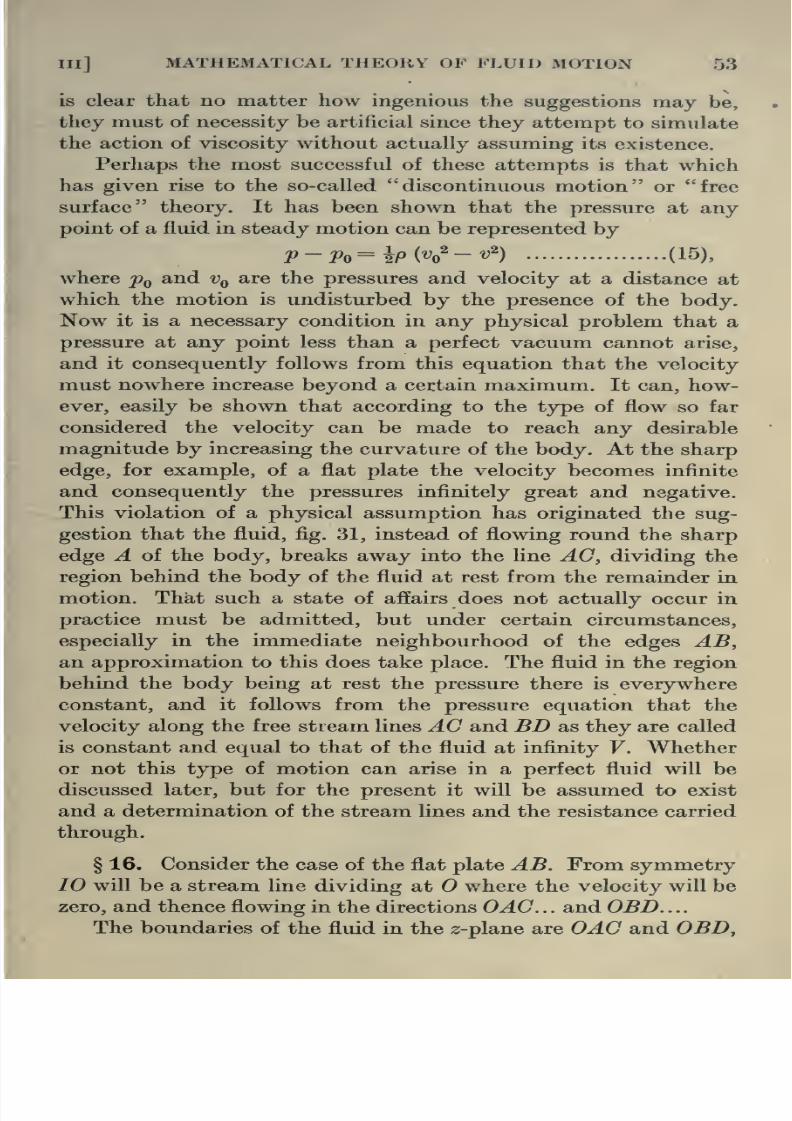
8/13/2019 Aeronautics in the 00 Cow Lu of t
http://slidepdf.com/reader/full/aeronautics-in-the-00-cow-lu-of-t 77/365
hn] MATHEMATICAL THEORY OF FLUID MOTION 53
is clear that no matter how ingenious the suggestions may be,
they must of necessity be artificial since they attempt to simulate
the action of viscosity without actually assuming its existence.
Perhaps the most successful of these attempts is that which
has given rise to the so-called discontinuous motion or free
surface theory. It has been shown that the pressure at any
point of a fluid in steady motion can be represented by
p-Po=ipW-v^) (15),
where Pq and Vq are the pressures and velocity at a distance at
which the motion is undisturbed by the presence of the body.
Now^ it is a necessary condition in any physical problem that a
pressure at any point less than a perfect vacuum cannot arise,
and it consequently follows from this equation that the velocity
must nowhere increase beyond a certain maximum. It can, how-
ever, easily be shown that according to the type of flow so far
considered the velocity can be made to reach any desirable
magnitude by increasing the curvature of the body. At the sharp
edge, for example, of a flat plate the velocity becomes infinite
and consequently the pressures infinitely great and negative.
This violation of a physical assumption has originated the sug-
gestion that the fluid, fig. 31, instead of flowing round the sharp
edge A of the body, breaks away into the line AG, dividing the
region behind the body of the fluid at rest from the remainder in
motion. That such a state of affairs does not actually occur in
practice must be admitted, but under certain circumstances,
especially in the immediate neighbourhood of the edges AB,
an approximation to this does take place. The fluid in the region
behind the body being at rest the pressure there is everywhere
constant, and it follows from the pressure equation that the
velocity along the free stream lines AG and BD as they are called
is constant and equal to that of the fluid at infinity V. Whether
or not this type of motion can arise in a perfect fluid will be
discussed later, but for the present it will be assumed to exist
and a determination of the stream lines and the resistance carried
through.

8/13/2019 Aeronautics in the 00 Cow Lu of t
http://slidepdf.com/reader/full/aeronautics-in-the-00-cow-lu-of-t 78/365
54 AERONAUTICS IN THEORY AND EXPERIMENT [CH
where OA and OB are straight Hnes, but the shapes of AC and BDare for the present not known, and not necessarily straight lines,
and it will consequently not be possible to apply the Schwarz-
ChristofEel theorem directly to effect a transformation of the
region of the fluid in the 2-plane to the upper half of a ^plane.
One fact however is known about the stream line AC—the velocity
along it is V. For one part of the boundary the direction of motion
is constant, and for the other the magnitude. If therefore a new
complex plane, transformable to the 2;-plane by some known
relation, could be derived in which the one axis was a function
of velocity and the other of direction of motion, the boundaries
in it corresponding to those of the 2;-plane would be straight lines.
Such a relation can be simply derived as follows
dw dch^
.dib .
, dz , U + iv , I /U ^ .V\ , 1 . n ,
- • m.'. log y- = Jog -^——^ = log - - + ^ - = log - (cos 6 + ism 8)
^dw ^u^+ v^ ^ q\q ql ^ q
= log - e' = log - + id,
^q ^q
where q is the resultant velocity and the direction of motion,
at any point. This formula ^^ ^t'O
provides a new and con-venient plane of representa-
tion for the type of problem
under discussion.
It will be assumed that
the values of t at the various
points are as shown in the Fig- 31
figure and that the velocity at an infinite distance is unity, so
that this is also the constant velocity along the free stream fine.
Writing ^ , „„ . ., ,,
^ aw ~ q
along OA,
atO,
Z'+OO
a = ]
6>=-77/2,
q- 0, .'. log 1/? = - 00

8/13/2019 Aeronautics in the 00 Cow Lu of t
http://slidepdf.com/reader/full/aeronautics-in-the-00-cow-lu-of-t 79/365
«] MATHEMATICAL THEORY OF FLUID MOTION 55
SitB, q=l, .-.log 1/^-0,
along BD, O^d ^+ 77-/2.
The following figure may accordingly be constructed for the
^-Plane Q ^ log i/g + ie,
tizL ±^
i'O-
I^ i-+oo
Fig 32
where the corresponding values of t are given, the polygon to be
transformed by the Schwarz-ChristofEel method being OABO of
internal angles 7r/2 both at A and B.
Hence ^^ = C {t - l)-^'^ {t + l)- '^ = C|^/{t^ - I),
and therefore^^c\og[t+ Vit' -l)] + D.
To determine the constants we note that
+ 00 >t^l, \ogllq + id=C\og[t+V{r ~l)] + D.
At A, t=l, q=l, e=^-7Tl2,
.-. D - - 77^72.
1 ^ ^ ^ 0, log yq + ie=C log [t + i^/{l - t^)] + D
= Caan-V(l - ^^)A + Alog l/q + ie=^C\og[-t-iV{l - t^)] + Glog{-l) + D
= (7 log [- ^ - *V(1 - ^^)] + G7Ti + D
= C tan-1 ^(1 _ i2)n _^ Ctti + 2).
- l^^^-oo, logl/(/ + t^=Clog[-^+V(^2- i)-] + C7ri+D.
At 5, ^=-1, ?-=l, 6>=7r/2,
/. 0=1.
Hence log£ = Q = log [t + V(^' 1 )]- W^,

8/13/2019 Aeronautics in the 00 Cow Lu of t
http://slidepdf.com/reader/full/aeronautics-in-the-00-cow-lu-of-t 80/365
56 AERONAUTICS IN THEORY AND EXPERIMENT [CH
^= + 0, 0= — at 0, the value of </> is zero. The i<;-plane is then
as shown in fig. 33.
^,^oo A JLt'O€—00'^
3 n'^'O
w-plane.
Fig. 33
The region occupied by the fluid now corresponds to the whole
of the t<?-plane bounded internally by the two lines OC and OD
lying infinitely close to the axis. For a direct application of theSchwarz-Christoffel method it will be necessary to deal with the
w-^--p\a,ne where the point at which t becomes infinite will be
at infinity.
.i-n^ ^ -J -.^.n
-J i'+oo
w~^-plane.
Fig. 34
The internal angle of the polygon is 2n- at ^ = 0,
.-. w-i = filE + F.
When t = 0, w^ = since </ is infinite there, and consequently
rfz
and ^= '1^^ + ^^^' ^^^
are the two relations from which w in terms of z is to be derived.
Along the stream line 0=0,
dx^.dy dz .^ . ..,„ ..v
a<p acp a<p
:. ^- = and ^ - - it - iVit - 1) along OA,cUp d(p

8/13/2019 Aeronautics in the 00 Cow Lu of t
http://slidepdf.com/reader/full/aeronautics-in-the-00-cow-lu-of-t 81/365
[ill] MATHEMATICAL THEORY OF FLUID MOTION 57
wJiere 21 = total breadth. Along the free stream line,
l%t^O, log
^= log [« + iV(l - t^)] - W2- i [tan-V(l - ^^)/« - ^/2]
= log l/q 4- id,
:. ^-tan-V(l-^^)A- W2,
giving t = sin 6.
Moreover g' = 1 = -p ,
and cf>=^l/{7T + 4)fi=^ll(7r-\-4)sm^d,
and the intrinsic equation to the free surface is
measuring 5 from the centre of the plate.
From these equations the expressions for x and y are easily
derived, viz.i
X = -. (cot 6 cosec 9 — log cot ^/2),TT + 4
y = 7 (1 — cosec 9),
from which the free stream line may be easily plotted. Both x
and y become infinite together.
§ 17. Calculation of Thrust on Plane. On any element dy of
the plane the pressure on the up-stream side is ^q + o^^^ ~ 5'^)'
and Pq on the down-stream side where V = velocity of the steady
stream at infinity, taken in this case to be unity.
Hence
Total thrust = 2f' Ifo + ^i^ - f) - Po~\dy = P
f
{^ - f) dy
Now for this range of t we have found that
iiq=t+v{t'-n

8/13/2019 Aeronautics in the 00 Cow Lu of t
http://slidepdf.com/reader/full/aeronautics-in-the-00-cow-lu-of-t 82/365
58 AERONAUTICS IN THEORY AND EXPERIMENT [CH
§ 18. Symmetrical Flow past a Curved Boundary. It has been
shown in a paper by one of the authors* that by the addition of
expressions for Q. for symmetrical flow past planes, cases of flowpast curved barriers may be obtained. It will be sufficient to
illustrate with the following example,
Q = log llq +id=^\ log [t + V(«^- 1)] + i log
p-±v|izL^)
Consider the intervals for t,
+ 00 >t>2,Vq = Wit +1)+ Vit - 1)] Wit + 2) + Vit - 2)]/2 v/2,
log 1/^ + ^•6I = 1 log [t + V{t' - 1)] + i log^ + ,y(4_^2)
]•
.-. i/g=[V(^+i)+V(^- 1)1/2,
^ = 1 tan-V(4 - ^ )/^.
log l/q + id =-ilog [t + V(l - ^^)] + ilog pJllV^tzii')
^ =-- 1 tan-V(l - i^)li + i tan-V(4 - t^)lt, etc.
It follows that for the range + oo > ^ $> 2 and — 2 5 ^ > — 00
the boundary is flat, but for 2 ^ i > 1 and — 1 ^ ^ ^ — 2 it is
curved, 6 being given in the range by
^ - 2 cos W,
At ^ = 1, d=^ 30°.
The expression for iv is, as in the preceding example,
w=^EIt\
The form of the boundary and free stream line is shown in
fig. 35, and the total thrust on the surface may be derived by
exactly the same process as that previously adopted, care being

8/13/2019 Aeronautics in the 00 Cow Lu of t
http://slidepdf.com/reader/full/aeronautics-in-the-00-cow-lu-of-t 83/365
Ill] MATHEMATICAL THEORY OF FLUID MOTION 59
the nature of the flow will be totally independent of the shape
of the surface lying within this region, and consequently the above
analysis treats the case of the discontinuous motion past a
Fig. 35
strut. The fact that in this case the flow and accordingly also the
resistance is unaffected by the shape and length of tail should
however be specially noticed and will be referred to later.
§ 19. Flow past an Inclined Plane. Let 10 be the stream
line j/r= which impinges on the inclined plane at where the
velocity is zero, and divides along OBD and OAC, and suppose
the values of t distributed as in fig. 36, where a is the inclination
T=cosc&
Fig. 36

8/13/2019 Aeronautics in the 00 Cow Lu of t
http://slidepdf.com/reader/full/aeronautics-in-the-00-cow-lu-of-t 84/365
60 AERONAUTICS IN THEORY AND EXPERIMENT [CH
Along OA, 6 ^ a— TT and q ranges from to 1.
Along AC, q is unity and 6 ranges from a — tt to 0.
Along OB, 0= a and q ranges from to 1.
Along BD, q is unity and 6 ranges from a to 0.
The corresponding Q-plane is thus fig. 37.
Applying the Schwarz-ChristofEel theorem the same formula
for transformation as before is derived, viz.
where the constants G and D are now to be selected to satisfy
the new conditions.
+ 00 >t^ 1,
log l/q + id=G log [t + V(^' - 1)] + D.
t<vb
i-1 i—oo—O
t=CO3C0
T^gJ^
TT^ i'-¥oo
Fig. 37
At^,
1 ^ ^ S> 0,
t=\, q=\, e={a-7r),
log Ijq + ie=C log [t + V(l - t^)^ + D
= a tan-V(l - ^^)A + (« - tt) i-
log l/q + id =-- C log [- t - V(l - t'^)] + C7ri-\-D
= C tan-V(l - t^'Vi + Ctt* + (a - tt) i.
-l^t>- 8,
log l/q + id=C log [- t + ^/{t^ - 1)] + Cni + (a - tt) i.
At B, t^-1, q=l, e=a,

8/13/2019 Aeronautics in the 00 Cow Lu of t
http://slidepdf.com/reader/full/aeronautics-in-the-00-cow-lu-of-t 85/365
Ill] MATHEMATICAL THEORY OF FLUID MOTION 61
dz•'•
dw ^ ^^^^ ~ * ^ ^ ^ ^^ ^ ^^^'^ ~ ^ ^^'
and w = El{t — cos of.
Along the stream-line i/» = 0,
</» - ^/(« - cos a)2,
^ + «:^ = (cos a - i sin a) [t + V('^ - 1 )]•
Hence along OA,
^ = cosa[( + V('^-l)],
and ^ = -sina[< + V('^-l)].
By integration, the coefficient E is immediately expressible in
terms of OA.
Similarly along OB,dx dvj7 + * -^ = (cos a — i sin a) \t — ^/(l'^ — 1 )],dcff acp
.•.g = cosa[<-V(«'-l)],
and ^=sina[(-V(«^-l)l.d(p
and by integration, a relation is obtained between E and OB.
Taking as before the breadth of the plane as 21 this provides
^ Zsin^aE= ^ —
7T sm a + 4
and determines the distance of 0, the point at which the fluid
divides, from the edge.
To derive the resultant pressure normal to the plane it is
necessary to integrate
^p(l — q^)ds or p (l/q — q) qdxj^ cos a
over the plane. The process is exactly analogous to that already
given for the case of a = 7r/2 and gives as result

8/13/2019 Aeronautics in the 00 Cow Lu of t
http://slidepdf.com/reader/full/aeronautics-in-the-00-cow-lu-of-t 86/365
62 AERONAUTICS IN THEORY AND EXPERIMENT [CH
§ 20. Flow past a Cambered Plane. It has been shown that
problems dealing with the impact of a fluid against a symmetrical
body, such as a strut, may be derived by the appropriate addition
of two expressions for O applicable to cases of the impact on a
plane. By a similar means solutions of problems of the flow past
cambered planes may be constructed.
Consider two expressions for Q. applicable to the flow past
planes where B successively corresponds to ^ = — 1 and to ^ = — 3
say. These give
and ^2= C'alogC^ + 1 + a/(^- 1) {t + 3)] + D^
respectively.
As a particular case consider
n = ^logu + vit' - ^)] + i^og[t+ 1 + v{t-i) {t + '?>)]
+ ^ (tt — a)
= logV(^ + i) + V(^-i)
V2logf
V(^-i) + V(^ + 3)-
+ i{7r — a)
with the same expression as before for w, viz. w = El{t — cos a)^.
Then
+00
>^ ^ 1,
Vq = [V(t + 1) + Vit - 1)] Wit - 1) + vit + 3)]/2 V2,
6^ 7T— a,
and therefore this portion of the plane is not cambered.
a=log'V{t+l)+iV{l-t)'
V2
+ logV(i-0 +W + 3)'
q=l,
which corresponds to the free stream line.
- -
+ i{7r- a),

8/13/2019 Aeronautics in the 00 Cow Lu of t
http://slidepdf.com/reader/full/aeronautics-in-the-00-cow-lu-of-t 87/365
MATHEMATICAL THEORY OF FLUID MOTION 63
I
V(-<-i) + V(i-0^2
H-iog.+,:ta„-.^(;-i;
+ i {n. - a),
.-. i/^^[V(-«-i)+V(i-0]/V2,
^ = 377/2 - a + tan-V(l - OM^ + 3),
giving the velocity and inclination at each point of the cambered
portion of the plane.
- 3 > ^> — 00,
i^(-t-l) + i^(l-t)lQ = log
+ log[
y2 J
+ i{7r-a),
.*. Vq= [Vi- t--i)+V{i- 1)] [V(i -t)+Vi-t- 3)]/2 V2,^=27r-«,
showing that the remainder of the plane is uncambered.
Fig. 38 shows the cambered plane, and the nature of the
flow past it. By an alteration of the constants occurring in the
t'-3
Fig. 38
expression for Q, problems relating to planes cambered in the
opposite sense and situated at any angle of attack to the directioii
of the fluid motion at infinity may be solved.
§21. When the surface is concave to the fluid so that the
dead water region is in the rear and upwards from the plane,
a positive lift will of course be produced, but it is clear that the
shape of the upper surface of the aerofoil will in that case have
no effect whatsoever on the nature of the motion and consequently
on the forces exerted. Now experiments on aerofoils in air have
undoubtedly shown that the upper surface and particularly

8/13/2019 Aeronautics in the 00 Cow Lu of t
http://slidepdf.com/reader/full/aeronautics-in-the-00-cow-lu-of-t 88/365
64 AERONAUTICS IN THEORY AND EXPERIMENT [cH
discontinuous flow of a perfect fluid, whereas in actual reality
that portion of the strut plays an extremely important part, on
account of the steadying influence it exerts upon the flow. It
would appear, therefore, that although surfaces acted upon by a
perfect fluid flowing in the manner here supposed do experience
a resistance, that resultant thrust is totally uninfluenced by the
very factors that regulate it in the case of a real fluid. In a number
of other respects a vital difference exists. Far from the region in
the rear of the body being one of calm ''dead water, it is in fact
generally one of violent turbulence and as such is equivalent to
a dissipation of energy that finds no place in the problem discussed.
A free surface, moreover, involving as it does a discontinuity in
velocity over its boundary, is in reaUty a vortex sheet, and
consequently is highly unstable, tending to roll itself up at various
points and thus form a series of isolated vortices or eddies. The
exact nature and action of these will be discussed later. In spite
of all these objections nevertheless it is remarkable, even admitting
the assumptions, that the results obtained for the resistance are
comparable at all with those derived by experiment, although
deficient in the respects indicated. A considerable volume of
discussion among mathematical physicists has centred round the
question of the applicability of the state of discontinuous motion
even to a perfect fluid. It is clear that the state of affairs supposed
existing would not originate in a fluid in a finite time since it would
necessarily, if allowed, curl closely round both sides of the obstacle.
The motion may, however, be gradually approximated to, by
supposing a surface of exactly the dimensions and curvature of the
calculated free stream lines to occupy its position and the fluid
allowed to flow past it and the body. When the motion has attained
steadiness, if the surface be supposed removed without the intro-
duction of any disturbance, a state of discontinuous flow will have
been brought into existence. It may be mentioned that the
method of this section finds a legitimate application however in
the theory of jets.

8/13/2019 Aeronautics in the 00 Cow Lu of t
http://slidepdf.com/reader/full/aeronautics-in-the-00-cow-lu-of-t 89/365
in] MATHEMATICAL THEORY OF FLUID MOTION 6
on the one side of the body and accelerated on the other. Since
this involves an increased and a diminished pressure respectively
on opposite sides, a resultant force will be originated, ft can be
shown that this force is proportional to the intensity of the cyclic
motion and is thus apparently quite arbitrary. The method more-
over gives rise to a lift on the aerofoil and no drag. It is not
proposed to enter here into a discussion of this method for which
the student is referred to Aerofoil and Propeller Theory by F. W.
Lanchester.The failure of the various treatments of the problem of the
motion of a body and the forces experienced to approximate to
that of practice is evidently due to the supposition that the fluid
dealt with is perfect. The mathematical treatment of a viscous
fluid is exceedingly intricate and merely the fringe will be touched
in the present chapter. Nevertheless, the value of investigations
of the behaviour of a perfect fluid is considerable for the light it
throws upon the nature of the so-called stream line motion,
and the ideal, never attainable, towards which to strive in design.
Rotational or Vortex Motion in a Perfect Fluid
§ 23. Attention has so far been confined to the problem of
the steady motion of a perfect fluid devoid of vorticity, and thereremains for discussion the second class of cases in which this
restriction is no longer imposed. In §§ 6 and 7 it was seen that the
intensity of spin, or the instantaneous angular rotation at any
point, was measured by the expression
V^ = f(x,y),
or, as it shall be referred to here,
V2^=2^ (22).
The function t, is not restricted in any way. It may be a con-
tinuous function of position or it may exist only at discrete points,
but it must be noticed that any region of the fluid in which t, does
not exist may be treated as irrotational, for which there will exist

8/13/2019 Aeronautics in the 00 Cow Lu of t
http://slidepdf.com/reader/full/aeronautics-in-the-00-cow-lu-of-t 90/365
66 AERONAUTICS IN THEORY AND EXPERIMENT [CH
is referred to Lamb's Hydrodynamics. The following apply
generally to three dimensions.
{a) A vortex line—a line in the fluid coinciding at each point
with the axis of rotation there—cannot begin or end at any point
of the interior of a fluid. Any vortex lines which exist must either
form closed curves or else traverse the fluid beginning and ending
on its boundaries. This presupposes that the velocities are con-
tinuous.
(6) Vortex lines move with the fluid.
(c) The strength of a vortex—twice the product of the
angular velocity and the cross section—is constant with respect
to time, if a potential function exists for the external forces
operating on the fluid.
{d) The motion of an incompressible fluid which fills all space,
at rest with infinity, is determinate when the value of the vorticity
is known at all points.
§ 24. To commence with the simplest problem in two dimen-
sions consider the case where there is no vorticity in any part
of the field except at the origin of coordinates at which point
there exists a single vortex of constant strength K.
Since all directions are identical in relation to the vortex,
the motion at any point and the function determining it, ^, mustdepend solely on the distance r from the origin.
Writing r^ = x^ + y'^,
we find that
^ cx^ cy^ dr^ r dr r\ dr^ drj
Id f dxb
r dr\ dr
My^^^ <^3).
If a be the radius of the vortex 27Ta% wijl be its total strength,
.'. 2TTa% = K from r = to r = a,
^ = from r = a to r = oo .

8/13/2019 Aeronautics in the 00 Cow Lu of t
http://slidepdf.com/reader/full/aeronautics-in-the-00-cow-lu-of-t 91/365
Ill] MATHEMATICAL THEORY OF FLUID MOTION 67
(i) Outside the vortex ^^ 0,
dr r'
.'. ils= A log r -\- B.
If j/f = when r = a,
ilf=A log r/a.
The velocity at any point is then
8i/f _ Adr _ A If
dy r dy r'
r'
dijj Adr _ A x
dx r dx r'r'
At r= a, u= — Ayjd^ v = Ax/a^.
(ii) Inside the vortex ^ is constant; integrating (24)
== ?r2/2 + A^ log r + B^
^^r^-a^)l2 + Ai\ogrla, .
since j/» = when /• = a.
Since i/j is not to be infinite when r= 0, A^ must be zero.
:. u=-t,rylr=-iy,
v=-{-
l,rxlr =l,x.
In order that the velocity at the boundary of the vortex may
be continuous it follows that
ly= Ayla^ l^x= Ax/a^,
:. A=^^a^=KI27r.
Accordingly the stream function outside the vortex becomes
i/j = {a^ log r/a = ^r- log r/a,
and the component velocities
^a^ y la' x # la - K 1
r r r r dr r ztt r
The velocity is thus at any point directed perpendicular to the

8/13/2019 Aeronautics in the 00 Cow Lu of t
http://slidepdf.com/reader/full/aeronautics-in-the-00-cow-lu-of-t 92/365
68 AERONAUTICS IN THEORY AND EXPERIMENT [cH
omitting the constant term, may be represented in a form more
convenient for further development.,
^j
Since apart from the origin no vor-|
^v kj^
ticity exists in the fluid, for all\-K v ^ \2n Fz
other points in the field a potential ; ^J^^^function must also exist. This is ^i^™- -of course the function conjugate to
I
the above and is easily derived ^m. 39
from it.
It has already been seen that
log z = log {x + iy) = log re^^ = log r + id.
The function conjugate to log r is thus Q, and accordingly
w=(f)
i- iil;= iKI27T . log z
gives the relation between w and z for the fluid outside the origin.
Generally
w=iKI27T .log (z-Zq) (25)
is the solution for a vortex situated at the point
Zq= Xq-Jt i?/o •
§ 25. From this single illustration may be derived the nature
of the motion in any case in which a number of vortices of this
nature are situated at given positions in the fluid. Two principles
are utilised in such a determination. It has been shown earlier
in this chapter that when the motion of the fluid is determined by
linear differential equations of the type here involved that the
stream functions for any number of possible motions may be
added and a new type of possible flow derived such that the
velocity at any point is simply the vectorial sum of the component
velocities due to each of the superposed types of flow. This con-ception will be here applied to the case where any number of
discrete vortices exist, by superposing on any point the component
motions due to each of the vortices separately. In the second place,
since these vortices must move with the fluid, any single vortex
must have imparted to it the motions at that point due to all the
others. The method will become clear by considering the case of

8/13/2019 Aeronautics in the 00 Cow Lu of t
http://slidepdf.com/reader/full/aeronautics-in-the-00-cow-lu-of-t 93/365
Ill MATHEMATICAL THEORY OP FLUID MOTION
with the same velocity. The whole system thus moves forward
withconstant speed Kjiira in the positive direction. The stream
function and consequently the stream lines also are easily deduced
from the analysis of the last example.
For the vortex at A,
w = iKj^TT . log {z — ai),
and for A', w-= — iK/'In . log (z + ai).
r^ 2n 2cL
a
L.W ^ K,J_'^T ^2n ZcL
Fia. 40
Superposing these two systems the stream function for the final
state of motion is given by
, . iK. , ., iK ,, ,
.. iK . z — aic|>+^4s^w-=^\og(z-a^)-^\og(z+a^) = ^\og^-^..
Hence
27r
'f'^^TT^^x'^+iy + aY'
In order to obtain the stream lines corresponding to a system
of axes continually occupying the same position relative to the
two vortices, that is, moving with them, it will be necessary to

8/13/2019 Aeronautics in the 00 Cow Lu of t
http://slidepdf.com/reader/full/aeronautics-in-the-00-cow-lu-of-t 94/365
70 AERONAUTICS IN THEORY AND EXPERIMENT [CH
(26).
Such an expression is KylArra.
Hence finally
0=^log -^±it^V^^ i7r^x^+ iy + a)^^ iira
An analysis of the system of curves given by this equation for
a series of values of i/j indicates that they are of the nature shown
in fig. 41. The stream fine i/j=0 consists of the Z-axis and an oval
enclosing the two vortices, moving with them and continually
enclosing the same fluid.
§ 26. Following the method thus indicated the more com-
plicated case of two pairs of vortices and their mutual effect can
be easily developed. The detailed calculation of the stream lines
in this case (fig. 42) is left to the student but the general motion
of the vortices can be easily seen.
(-oc,i/>
i-x.-y)
A (x,y)
4'nW(x2+y2)
(Xry)
Fia. 42
If the origin be situated symmetrically between the four
vortices K at (a?, y),— Z at (— a?, y), K at (— x, — y), and — Z at
{x, — y), say A, B,C, D respectively, then the velocities imparted
to A by the remaining three are as indicated above.
dx uAI
If -T- and^ are the component velocities of A, thenat at
dx 1 y_ K 1 Kdt~ 47r
•
2/
^477 '^/{x^ + if) 'V{x^ + «/')
K47r'y{x^ + y'^)

8/13/2019 Aeronautics in the 00 Cow Lu of t
http://slidepdf.com/reader/full/aeronautics-in-the-00-cow-lu-of-t 95/365
III] MATHEMATICAL THEORY OF FLUID MOTION 71
On integration this furnishes the path traced out by the
vortex as1/^2
_|.
1/^2 _ 1/^2^
It appears at once from this that the two pairs of vortices approach
each other asymptotically, each moving meanwhile further away
from its partner.
It must be noticed that OX and OY from conditions of
symmetry are evidently stream lines and may therefore be taken
as rigid boundaries. The above analysis thus gives the path traced
out by a vortex in the vicinity of a corner, or alternatively the
manner of approach of a pair of vortices to a plane surface.
The student will find it an interesting exercise to trace the
mutual effect of such a double pair when those at B and are
identical in strength and sign with those at A and D respectively,
the latter two being equal in magnitude but opposite in sign. The
foremost pair it will be found widen while the pair behind comecloser together and then shoot through the pair in front.
§ 27. Photographs illustrative of the nature of the flow behind
a moving body have been given in Chapter II. It is clear that for
at least a short time after their production the eddies or vortices
brought into existence in the immediate wake of the body ap-
parently adopt and retain a very definite arrangement. Byassuming a system of vortices situated similarly to those shown
in the photographs mentioned, it will be seen, even in the case of
fluid devoid of viscosity to which the present discussion is confined,
that the nature of the flow and stream lines bears a close resem-
blance to that actually photographed.
It will be supposed that the vortices are situated in two
infinite rows, all of strength + ^ in the one row, and — ^ in the
other.
Let their positions be as indicated below.
The values oi z^ x + iy for the eddies are then
(1) Top row, of strength + K,
{Aq, hi): {A, 21 + hi)\ {B, U + hi): ...,

8/13/2019 Aeronautics in the 00 Cow Lu of t
http://slidepdf.com/reader/full/aeronautics-in-the-00-cow-lu-of-t 96/365
72 AERONAUTICS IN THEORY AND EXPERIMENT [CH
Remembering that the relation between z and w for a single
eddy at 2; = ^Jq is n^
277log (2 - 2o) (25),
it follows that the complete expression for this case is
%Ki^' = 2 [log {z - hi) + log (2 - 2? - hi) + log (z — U — hi) . .
+ log (z+2l- hi) + log (z+ il- hi)...
- log (2 - ? + hi) - log (2-
3? + Ai)...
- log (2 + Z + hi) - log (2 + 3? + A*) ...]
= */{log (2 - ^*) + log [(2 - /^^)2 - 4^2] + log [(2 - hi)^- 161^] . .
- log [(2+ hif - ¥\ - log [(2 + hif - 9/2] . . .}
_iK (2 - hi)\{z - UY - m\{z-hif-\m\ ...
~271
^^[(2 + A^)2-/2][(2+^l)2-9|2]...
Y5' 4'
-^^--^ f-2l--
iv n• *
'1
4'
^r 7^
^
^
X
Fig. 43
For simplicity let —^— =jp and —,—
formula may be written
(-S)O-i:)-
g', then the above
+ constant.
Now it is well known that sin and cos may be expressed as
products in the following form

8/13/2019 Aeronautics in the 00 Cow Lu of t
http://slidepdf.com/reader/full/aeronautics-in-the-00-cow-lu-of-t 97/365
Ill
^ ^ = - sin ^'
Hencei'
(l -f^j ^1 - 42J
- =-^/2- =7r
and M -^g) (
^ ~ Iv• * •
^^^ ^^^/^ ^^^
2Z'
»2\ / «2\ 77(2 — /i*)
11'
The relation between w and 2 which furnishes all the circumstances
of the motion is thus, omitting the constant terms,
^ + ^^ := 1^ = -— log -—cos
^[z + hi)
Fig. 44
Separating the real from the imaginary parts it follows that the
stream lines are given by
^ coshy {y — h) — cos ,
= -^log'. L
(27).
coshJ{y + h)+ cos -y-
The form of the stream lines is shown in fig. 44.

8/13/2019 Aeronautics in the 00 Cow Lu of t
http://slidepdf.com/reader/full/aeronautics-in-the-00-cow-lu-of-t 98/365
74 AERONAUTICS IN THEORY AND EXPERIMENT [cH
out in the previous chapter, and it is here proposed to indicate
how the nature of the flow of such fluids may be investigated
exactly in a few simple cases. The solution of the general equations
of the motion of a viscous fluid, subject to given boundary con-
ditions, would clarify at one stroke the whole problem of aero-
dynamics, but, unfortunately, mathematical theory has not yet
been sufiiciently developed to effect this. Two facts already
discussed at some length will be recalled.
(1) If dv/dn be the velocity gradient perpendicular to thestream lines at any point, and if F be the viscous dragging force
existing there per unit area, then
where /x = coefficient of viscosity.
It is morecustomary and convenient to deal with the coefficient
of kinematic viscosity = v= jji/p.
(2) Experience appears to indicate that at the surface of
contact between a solid and a viscous fluid there is no relative
motion of the solid and fluid in immediate contact with it, other-
wise an infinitely greater resistance would require to be opposed
to the sUding of one portion of the fluid past another than to the
passage of the fluid over the solid.
§ 29. Steady motion of a viscousfluid under pressure between two
fixed parallel walls. Supppse the fluid flowing steadily between
the walls AB and CD, in the direction OX, and consider the
forces upon any small element SxSz. The resultant pressure
thrust in the direction OX is
pSz — Ip -h J-Sxj Sz= — -~- SxSz.
If u be the velocity at the element, the positive traction due to
vuviscous forces on the under surface of the element is u ^— Sx
^ dz
and that on the upper surface

8/13/2019 Aeronautics in the 00 Cow Lu of t
http://slidepdf.com/reader/full/aeronautics-in-the-00-cow-lu-of-t 99/365
Til] MATHEMATICAL THEORY OF FLUID MOTION 75
Since the motion is steady the pressure and viscous forces alone
determinethe motion
within the given boundaries
— ~ OXOZ = — LL-^r^bZOX.ex cz^
dp dhi
dx=^d?(^^^-
The corresponding equations for motion in the directions OZ and
dy~^' dz~^'
and accordingly since the motion is steady so that the velocity
is not a function of x, the pressure gradient djj/dx must be an
absolute constant, 92^
.-. ti = - {z^ - h^),
making the velocity zero at z-= ± h, the sides of the channel.
fz
-B
I
Fig. 45
If M be the total quantity of fluid crossing any section per
second, ch ^j^hs
M = p\ udz= - ——.
J -h 3/x
Hence finally ^ = |-p (/*' - ^') (29).
This formula determining the distribution of velocity across
the channel has received ample verification mainly where the
fluid is water, and where the conditions regarding steadiness are
those assumed in the foregoing discussion. Actually for a channel

8/13/2019 Aeronautics in the 00 Cow Lu of t
http://slidepdf.com/reader/full/aeronautics-in-the-00-cow-lu-of-t 100/365
76 AERONAUTICS IN THEORY AND EXPERIMENT [CH
§ 30. Steady flow along a circular pipe. A similar problem
amenable to equally simple treatment is that of the steady flow
of a viscous fluid along a uniform circular pipe.
Let the axis of X be taken to coincide with that of the pipe
and let r be the radius to a point in the fluid in a plane perpen-
dicular to the axis. Consider the forces, viscous and pressure,
acting upon a tube of the fluid of length Sx, radius r and
thickness 8r. If u be the axial velocity at radius r then the
du
drviscous force per unit length on one side of the shell is /x
ouor round the whole shell ft -^ . 27rr, while on the other side it is
Hence the resulting dragging force over the length 8x is
d ( du^277-/X
dr{r{^SxSr.
2iTr (p+|..)«.
Fig. 46
The motion being steady, this must be balanced by the
pressures on the two ends of the tubular shell, the resultant of
which is clearly ^ ?> ^P?;
dx
Accordingly ^|(,|) = _,| (30).
Since the motion is everywhere longitudinal there are no viscous
forces radially and consequently the pressure variation in that
direction must vanish and therefore dp/dr must vanish. The left-

8/13/2019 Aeronautics in the 00 Cow Lu of t
http://slidepdf.com/reader/full/aeronautics-in-the-00-cow-lu-of-t 101/365
MATHEMATICAL THEORY OF FLl
The integral of this equation is evidently
The constants of this equation are to be determined from the
fact that there is no slip at the boundary and the velocity along
the axis must be finite, i.e. i^ = at r = i2 andu
finite at r = 0.
Hence(\f1(«^-'-^'
(^i)>
and the velocity distribution is apparently parabolic, the speed
at the centre beingPi - V2
4/x?,
m
§31. Steady flow under pressure between two concentric tubes.
The formula derived in the last example may be directly applied
in this case.
r^ + a loff r+b.
The boundary conditions are now w ^ at r= R and w = at
r= Rq. Inserting these in the equation it is easily found that
- vA R^ - Rn^
glVl
An
giving
u --=
. 4/x; ; \ogRIR,'
'Vi - V2\
. 4/xI)'{RoHogR-RHogRo
[ log R/R,
'Pi -P2\
4m/ ;{R'-r') + {R'-Ro
log r/R]
logR/Roi
(32)..
An interesting particular case arises when the radius of the
internal tube is vanishingly small, in which case, as the student
will easily verify by a consideration of the limiting values of
the expressions, the velocity distribution across the pipe is exactly

8/13/2019 Aeronautics in the 00 Cow Lu of t
http://slidepdf.com/reader/full/aeronautics-in-the-00-cow-lu-of-t 102/365
78 AERONAUTICS IN THEORY AND EXPERIMENT [cH
that it verifies in the case of that fluid the assumption here made
that there is no slip at the boundary. The results can likewise be
utilised for determining the coefficients of viscosity, for the total
volume of fluid crossing any section per second in the case of a
pipe of radius R is
2Trrudr= ^; \ ^^.
J OjJil
From a measurement of the quantity of fluid passing through
the tube per second /jl is at once calculable.
General Discussion and Derivation of Equations
§ 32. For further discussion it will be convenient to revert to
the method of treatment adopted in the earlier part of the previous
chapter where the fluid instead of being regarded as a homogeneous
medium is considered as composed of discrete particles or mole-
cules shooting about in all directions. If the two methods of
treatment are ultimately identical, the equations specifying the
motion of the medium should be the same for both. There are
certain aspects however of the motion of a viscous fluid such as air
which can be brought out more strikingly by regarding them from
the point of view of the molecular theory. It has already been
explained that wherever there exists a velocity gradient in themedium there exists simultaneously a so-called viscous force in
direction parallel to the flow and in magnitude proportional to
the velocity gradient. The coefficient of proportionality under
certain standard conditions was defined as the coefficient of
viscosity.
If a body be brought under the existence of an external force
of some nature forcing it through the medium, the particles coming
into contact with it either directly or through the agency of
intermediate particles will have communicated to them every
second a definite quantity of momentum in the direction of the
impressed force. This continuous exertion of an external force
clearly performing work upon the fluid must likewise ultimately

8/13/2019 Aeronautics in the 00 Cow Lu of t
http://slidepdf.com/reader/full/aeronautics-in-the-00-cow-lu-of-t 103/365
Ill] MATHEMATICAL THEORY OF FLUID MOTION 79
without affecting its absolute momentum by simply superposing
equal and opposite velocities upon two molecules of equal mass
within the element. If no further external force be impressed upon
the fluid beyond that exerted by the body already referred to, it
is evident that the total quantity of momentum being emitted
per second from that source will spread itself in all directions from
molecule to molecule throughout the region of the fluid, its total
magnitude remaining unchanged. It follows that if the body be in
motion in a fluid of infinite extent so that an infinite quantity of
fluid receives a finite increment in momentum per second, the fluid
at a great distance will be undisturbed. Stating this in more exact
form we may imagine a mass M per second of fluid at infinity
receiving an increment in velocity 8v per second so that M x hv
is the momentum passed out per second from the body through
the agency of the molecules and is finite. M being of infinite
magnitude, 8v is infinitely small. Consider the apparent energythis rhass of fluid receives per second. It will be of the order
^M (hv)^ so that the total quantity of actual translational energy
passed out per second at infinity is infinitely small. On the other
hand it has already been explained that the body in its motion
through the fluid is performing work at a finite rate which, on
the basis of the law of conservation of energy, must ultimately
make itself evident in some form, and the question naturally
arises—where does this energy exist? Now it has been seen that
each element of the fluid regarded as a whole may possess and
transmit a certain quantity of momentum to its neighbour but
may at the same time possess and accumulate energy regarded as
the sum total of the energies of the individual molecules. In fact
each element of the fluid acts as an agent totransmit momentum
in a given direction to all the neighbouring elements and in the
process without destroying any of that momentum increases its
own energy. If the motion of the element is to be considered, as is
done on the supposition of a homogeneous fluid already described,
then the visible energy of translation will be merely a portion of
this total energy and will be represented by ^mv^, where m is the

8/13/2019 Aeronautics in the 00 Cow Lu of t
http://slidepdf.com/reader/full/aeronautics-in-the-00-cow-lu-of-t 104/365
80 AERONAUTICS IN THEORY AND EXPERIMENT [CH
either from the molecular or homogeneous standpoint transmits
energy to the fluid both in the translational and in the heat form.
Ultimately the translational energy of any element becomes
infinitely small and merely heat energy remains.
§33. The vital distinction between a viscous fluid and a
perfect fluid becomes at once apparent from the above remarks.
The mere assumption, it has been seen, that the fluid is composed
ultimately of discrete particles is sufficient to bring into existence
a viscous dragging force. A perfect fluid where this force is non-existent must therefore be homogeneous throughout. The energy
which would otherwise be secreted in the form of internal mole-
cular energy, and consequently heat, no longer exists as such
and simply passes on purely into the translational form as under-
stood above. In the perfect fluid there is thus no apparent
dissipation of energy.
§ 34. General equations of viscous flow. The problem will be
restricted as before to two dimensions. Consider a small element
of fluid abed of dimensions hx and hy moving with component
djddr
Fig. 47
velocities u along ox and v along oy, fig. 47. According to the
kinetic theory of gases the molecules of the fluid are shooting about
in all directions so that inside ahed the most probable velocity of
any molecule in direction relative to the c.g. of the element is
the same for all directions. It follows that if a mass m of molecules

8/13/2019 Aeronautics in the 00 Cow Lu of t
http://slidepdf.com/reader/full/aeronautics-in-the-00-cow-lu-of-t 105/365
]Il] MATHEMATICAL THEORY OP FLUID MOTION 81
distant L from ah, then the momentum per second lost by the
u' -\- L ^\ , where u' is the
average velocity along ah and dujdy the gradient in direction oy
of the X component of the velocity, in the neighbourhood of the
element. In the same way if the molecules entering the element
across this face be supposed to come from a h'\ distant L from
ah, where the x component of the velocity is u' — L ^ , the
momentum gained per second by the element will be
mhx{u'-L^,
making a total loss per second through the transference across this
face of 2mLSx {dujdy). Now the average velocity of the fluid along
cd is u' -\-^ 8^, so that the momentum gained per second by
the element through the interchange of molecules over this face is
giving a resultant gain across the two faces of
[dy V dy
2mLSxSy ^—^ along ox (33),
since du'jdy = dujdy nearly.
Proceeding on the same lines as before it is easily verified
duthat the element will lose momentum at the rate of 2mL x- 8y
per second in the direction ox by transference across ad which
together with the gain across he gives an increase of
d^u
2mL8xBy ^^ along ox (34).
Adding this to (33) the net gain per second for the whole element
2»L8.S,g4J) (35).
The product 2mL is called /x, the coefficient of viscosity. The
expression (35) giving the gain in momentum per second in the

8/13/2019 Aeronautics in the 00 Cow Lu of t
http://slidepdf.com/reader/full/aeronautics-in-the-00-cow-lu-of-t 106/365

8/13/2019 Aeronautics in the 00 Cow Lu of t
http://slidepdf.com/reader/full/aeronautics-in-the-00-cow-lu-of-t 107/365
Ill] MATHEMATICAL THEORY OF FLUID MOTION 83
authors has shown, however, that the solution of the problem of the
steady motion of a body of any shape in a viscous fluid can be
reduced to the determination of the flexure of a flat plate loaded
and supported in a specified manner, and developments along
these lines would seem to indicate a method of attack to which
the equations may yield.
A complete solution satisfying the no slip condition at the
boundary for some particular problem would be especially
valuable for the light it would throw on the problem of how from
a state of motion instability and consequently turbulence arises.
This demands a mathematical expression showing the origin and
history of an eddy, but it has not yet been obtained. The progress
of the science is handicapped by insufficient mathematical
knowledge.

8/13/2019 Aeronautics in the 00 Cow Lu of t
http://slidepdf.com/reader/full/aeronautics-in-the-00-cow-lu-of-t 108/365
CHAPTER IV
FROM MODEL TO FULL SCALE
§ 1. As the result of years of scientific research a vast
amount of experimental data has accumulated concerning the
lift and drag of various forms of aerofoils, the thrust of pro-
pellers and the stability of different types of machines, and the
laws that govern these factors for varying forms of design of
the corresponding parts. To carry out the greater number of
these investigations with full scale machines or parts would
not merely be impracticable, inconvenient, and dangerous from
the experimental standpoint, but is impossible to any large
extent on account of the huge expense that would necessarily
be involved. Consequently models approximating only in rare
instances to full scale have been the principal objects of study.
An attempt to predict the behaviour of a full scale machine or
part from the model results brings the designer face to face with
a serious problem. A little consideration will soon show that
simply to increase lift and drag or propeller thrust of a model
in the ratio of linear dimensions of the full scale part to the
model, or even according to any simple law that could be framed
off-hand, leads to false conclusions. For a complete under-
standing of the question it is evidently necessary in the first
place, therefore, to determine what conditions, if any, allow of
the legitimate application of model results and to find the
factor and circumstances of transformation. It will be seen
that a moderately complete answer to this question may be
arrived at by nothing more than a mere application of Newton's
Laws of Motion, in their most general form, to the problem

8/13/2019 Aeronautics in the 00 Cow Lu of t
http://slidepdf.com/reader/full/aeronautics-in-the-00-cow-lu-of-t 109/365
Cll IV] FROM MODEL TO FULL SCALE 85
of which the length of some part to scale is I, the velocity v,
the effect of the earth's attraction conveniently represented
by g, the acceleration due to gravity, the density of the fluid p,
and the coefficient of viscosity /x. As far as the present problem
is concerned /x and p will be the only constants of the fluid that
affect the question, always provided the motion is not so great
as to cause the elastic properties of the medium to come into
play. Sufficient evidence exists to show that so long as the
velocity of the air is restricted below 200 miles per hour it acts
as an incompressible fluid.
It follows at once that the resistance R of the body
must be uniquely expressible in terms of these quantities,
and these quantities only, and it is accordingly legitimate to
write
R=F{vJ,p,fji) (1).
The precise form in which these four quantities are combined
to constitute the function F depends of course on the exact
shape of the body, for this is the only factor in the problem
that cannot be introduced in terms of a single measurable
quantity. In spite of this, however, it is possible to determine
quite simply certain general properties of the function
F which will yield the desired information. The method
that will be adopted is that known generally as the Method
of Dimensions and will be explained in detail in the next
paragraph.
§ 2. Dimensional Theory. Every symbol which can be
introduced to describe some dynamical or physical conception
such as length I, time t, speed v, acceleration a, force /, etc.,
must ultimately be expressible in terms of the three funda-
mental units or dimensions of length, time and mass. A speed,
for example, is a distance traversed divided by the time, and
consequently if length be represented dimensionally as L,
time T, the dimensions of a speed will be L/T. In the same
way an acceleration, being a velocity divided by a time, will

8/13/2019 Aeronautics in the 00 Cow Lu of t
http://slidepdf.com/reader/full/aeronautics-in-the-00-cow-lu-of-t 110/365
86 AERONAUTICS IN THEORY AND EXPERIMENT [CH
Quantity Symbol Dimension
Length I LTime t TMass m MSpeed V LITAcceleration a L/T^Force f ML/T^Moment M ML^/T^Density P M/L^Viscosity
f^ MILT
Kinematic Viscosity V L^ITConstant c Non-dimensional
If now for example a force / were to be expressed in terms
of any of the other qualities, say v, t, etc., it would follow that
these w^ould necessarily be combined in such a manner as to give
the dimensions of the total combination the same as that of a force.
Quite generally in fact all the terms of any combination of
quantities which state some physical or dynamical fact, based on
the ordinary laws of motion, must of necessity have the same
dimensions. This general property of any combination of such
symbols is known as Dimensional Homogeneity. The conception
will be made perfectly clear by a particular case. The formula
giving the time of oscillation of a simple pendulum is known to be
t = ^irVllg. The dimensions of the left-hand side being T, that
of ^/l|g must necessarily reduce to the same. The dimensions of
Vlfg are ^^(L ^ LjT^) = T.
§ 3. Application of the principle of Homogeneity ofDimensions.
The idea developed in the preceding paragraph now indicatesthat a certain degree of restriction must be imposed upon the
manner in which the symbols of any equation may be combined.
The following examples indicate how this method may be applied.
Example 1. To determine what may be discovered regarding
the velocity of gravity waves on the surface of an inviscid in-
compressible fluid by an application of the foregoing principles.

8/13/2019 Aeronautics in the 00 Cow Lu of t
http://slidepdf.com/reader/full/aeronautics-in-the-00-cow-lu-of-t 111/365
IV] FROM MODEL TO FULL SCALE 87
Suppose a term is quite generally represented by l^p^g' so that
its dimensions are
L' . {M/L^)y {L/T^Y = X«-3''+^ My/T^,
which must correspond to L/T the dimensions of a velocity.
Equating powers of L, M, T,
x-3y + z=l, 2z=l, y=0,
:.x=i, y=0, z=\.
Each term is therefore Vlg, that is to say there is only one term,
and it follows that ^ C\/ai (2)
where C is some constant; and this is the expression for the
velocity of heavy waves on the surface of a fluid.
Example 2. A body starting off with an initial velocity u
is under an acceleration g in any direction. It is required to
determine what information the preceding theory yields regarding
the distance traversed after a time t.
This distance can only depend on the quantities u, g, t and
the inclination of the direction of the acceleration at any time to
the direction of motion, but the latter cannot be expressed in
terms of any definite symbol. Each term in the expression for s,
the distance traversed, therefore, written in the form u^gyt^ must
reduce to the dimensions of s, viz. L. Now the dimensions of
u^gW are
(LjTY . (LITy . r^ = L^+y T^-^-^y = dimensions ois=L,
.'. X -\- y= 1, z — X — 2y = 0,
.'. y= 1 — X, z= 2— X.
:. W^gyt' = u'^g^-'^2-a; = gj^ [u/gtY.
. In this case the dimensional theory alone does not furnish
sufficient equations to determine x, but it tells us that every term
in the expression for s must be represented in the above form,
to which so far any value for x must be admissible. 5 in fact must
have the factor gt^ and the other factor must depend solely on the
quantity u/gt. This statement may therefore be written

8/13/2019 Aeronautics in the 00 Cow Lu of t
http://slidepdf.com/reader/full/aeronautics-in-the-00-cow-lu-of-t 112/365
88 AERONAUTICS IN THEORY AND EXPERIMENT [cH
function / cannot in this case be determined unless the relation
of g to the direction of motion etc. at any time be definitely
specified. If the acceleration g is always in the same direction as
the velocity, it is well known that
s=ut + lgt^=gtm^ulgt),
and therefore in this case
f(ul9t)=-l + ulgt.
It should now be evident to what this method reduces. The
replacing of the units of a force by ML/T^ etc. is equivalent to
Newton's Laws of Motion, and by their application in this very
general form sufficient information is derived to limit the form of
expression of any quantity, although the exact expression desired
will depend on something more. It will depend on the precise
manner in which these laws work themselves out in the problem
under discussion, and that again will involve such factors, amongothers, as the shape of the body, etc. It is moreover important
to note—and the full significance will appear later—that any
formulae we derive will apply so long as the quantities on which
the motion has been assumed to depend at any time remain the
only factors that determine the motion. Should any new factor
come into play the whole question will at once be transformed.
The fundamental assumption is, that the conditions of the motion,
partially expressed by the quantities whose dimensions come into
question, are such as to preserve that motion continually con-
sistent with these conditions, and these conditions alone. All the
apparent obscurities will be removed from this statement as soon
as we come to the problem to which we have gradually led up.
§ 4. To return now to the real problem of this chapter as
introduced in § 1, it was there seen that assuming the elasticity
of the fluid does not come into operation to any appreciable
extent the resistance of any body immersed in it will be expressible
in terms of v, I, p, fx, and the shape of the body which, however,
cannot be stated or defined by any single symbol. It must be

8/13/2019 Aeronautics in the 00 Cow Lu of t
http://slidepdf.com/reader/full/aeronautics-in-the-00-cow-lu-of-t 113/365
frv] FROM MODEL TO FULL SCALE 89
^wjxpVjj^z whose dimensions must be that of a resistance. The
dimensions of this expression are
which must reduce to the dimensions MLjT'^, that of a force.
Hence
y + z^l, w -\- X— 3y— z= 1, w + z=2,
.'. y= 1 — z, w== 2 — z, x=^ 2— z,
and each term is of the form
y2-z 12-z pl-z pz _ p,^J^2 (vlpl/ji)-^ = pvH^ (Vljv)-',
where v = fi/p, the kinematic viscosity. There are apparently not
sufficient relations among the quantities to determine z, which
may consequently be given any arbitrary value. The most
general expression for R will then be represented as a sum of any
number of terms of the above form and consequently the most
general expression will be given by
The terms in the square brackets depending as they do on the
quantity vl/v may be written quite generally/ (vZ/v).
Finally R == pvH^f (vljv) (4).
§ 5. If a body of given shape be immersed in a viscous fluid
and if its resistance be supposed defined purely by the velocity,
viscosity, density of the fluid and the size of the body, then the
expression for the resistance must take this form. The whole
problem of dynamical similarity, and the transition from model
to full scale hinges on the discussion of equation (4). It supplies
the basis for the experimental investigation by means of models
of the aerodynamic problems that occur in aeronautics. The
function involved depends for its form merely on the shape of
the body as defined by some drawing, but its actual value depends
among other things on the size. All bodies of the same shape but
of different dimensions immersed in different fluids and moving
with different

8/13/2019 Aeronautics in the 00 Cow Lu of t
http://slidepdf.com/reader/full/aeronautics-in-the-00-cow-lu-of-t 114/365
90 AERONAUTICS IN THEORY AND EXPERIMENT [cH
velocity v, and another on the corresponding full scale body of
length I, in another fluid of viscosity vj and density p^ and velocity
^1 *^®^ resistance of model =R = pvHJ{vllv),
and 'resistance of full scale = i^^ = piVi\Y i'^ihl^i)-
If the velocities, viscosities, and densities, be so selected that
vl/v = Viljvi = a,
then R/R^' = pa'^v'-f (a)lp^a^v^^J {a) = pv^jp^v^^ (5).
The resistance of the. full scale is thus expressed in terms of
that of the model, where it is especially to be noted that the
resistance of the model R is that at velocity v, and that of the
full scale R^ at velocity v-^ = vlvjl^v. v and Vi are defined as
corresponding speeds for bodies of the same shape whose dimen-
sions are given by I and l^ immersed in fluids of kinematic vis-
cosities V and Vi respectively.
Before proceeding further it may be necessary to restate some
of the conditions under which equation (5) is applicable as assumed
in its derivation and the implications that these involve. It was
in the first place supposed that the motion can be completely
expressed in terms of p, v, I, v, and consequently does not depend
on time explicitly. It follows that a picture of the flow and stream
lines at any time will always represent the flow and stream lines.
It is geometrically fixed and the motion is steady. Since
and this must be supposed to hold for all corresponding points
in the two fluids, the velocities at these points bear a fixed ratio
to each other depending merely on the nature of the fluids and on
the relative sizes of the two bodies. The expression deduced for
R must also be the form in which all the forces and their com-
ponents (shearing, etc.) which exist at corresponding points can
be thrown, and these also bear a constant ratio to each other for
corresponding points depending merely again on the nature of the
fluid and size of the bodies. All the forces being thus equal in
magnitude to a constant factor, and the same in direction, the

8/13/2019 Aeronautics in the 00 Cow Lu of t
http://slidepdf.com/reader/full/aeronautics-in-the-00-cow-lu-of-t 115/365

8/13/2019 Aeronautics in the 00 Cow Lu of t
http://slidepdf.com/reader/full/aeronautics-in-the-00-cow-lu-of-t 116/365
COMPARISON BETWEEN FLOW IN WATER AND IN AIR
Low value of vl Water
xW ^
High value of ul. Water

8/13/2019 Aeronautics in the 00 Cow Lu of t
http://slidepdf.com/reader/full/aeronautics-in-the-00-cow-lu-of-t 117/365
COMPARISON BETWEEN FLOW IN WATER AND IN AIR
Low value of ul. Air
High value of ul. Air

8/13/2019 Aeronautics in the 00 Cow Lu of t
http://slidepdf.com/reader/full/aeronautics-in-the-00-cow-lu-of-t 118/365

8/13/2019 Aeronautics in the 00 Cow Lu of t
http://slidepdf.com/reader/full/aeronautics-in-the-00-cow-lu-of-t 119/365
IV] FROM MODEL TO FULL SCALE 91
between the nature of the flow in air and that in water where the
similarity is well brought out, considering the experimental
difficulties involved.
§ 6. It is now evident that vl/v is a most important quantity
in any physical experiment on fluid motion, and provides the
criterion that the experimental facts derived from a model be
directly applicable to the corresponding full scale equivalent. In
general, however, conditions are from one point of view slightly
more simple, the model experiment and the full scale performance
taking place in the same medium, viz. air. Accordingly v= v^
and the criterion obtained demands
vl= Vili (6),
the densities and viscosities in the two cases being the same.
Equation (5) now becomes
R'IR,'^pv^lp,vi'=l (7).
When the experiment on the model is carried out at the same
value of vl as for the full scale, the resistances experienced in the
two cases are equal. It is this last deduction from the theory
of dynamical similarity that is of the most frequent and direct
application, but it demands a state of affairs which is extremely
difficult to attain in the course of normal experimental work.
For models of aerofoils tested in the artificial winds in channels
at aerodynamical laboratories, it is usually convenient to deal
with models about 1/25 full scale, and consequently to attain
values of vl of the order required for a full scale part it would
be necessary to carry out experiments at 25 times the velocity
of flight of the machine, or roughly 2000 m.p.h. To obtainanything even approaching this is manifestly impossible. The
highest velocity attainable in the new 7 ft. channel at the N.P.L.
does not exceed 60 m.p.h. Moreover even if the full vl could be
reached the forces which are brought into play, being equal to
those of the full scale machine, would be too great to deal with,
and measure accurately. It would appear therefore at the very

8/13/2019 Aeronautics in the 00 Cow Lu of t
http://slidepdf.com/reader/full/aeronautics-in-the-00-cow-lu-of-t 120/365
92 AERONAUTICS IN THEORY AND EXPERIMENT [cH
/ (vl/v) is determined for each value of vl/v in that range. If these
be plotted against vl/v, as will be done several times in Chap. VI,
it is found that as vl/v increases the curve tends to rise asympto-
tically to a certain definite value. This is equivalent to the state-
ment that the resistance tends to increase steadily as the square
of the velocity, for large values of vl/v.
Consequently what is normally done is, if possible, to carry
through the experiments up to such values of vl/v, or what amounts
to thesame
thing in this case vl, asshow the value oiR/pv'^P
to become sensibly constant, and then to extrapolate by extending
this curve to the higher values of vl. In practice for ease in extra-
polation it is customary to plot horizontally not vl but \ogvl
for this increases the horizontal distance for which we know the
values of R/pv'^P and decreases the extrapolated range. Many of
the figures occurring in Chap. VI illustrate this method. A
complete discussion, with applications, showing how to pass from
experimental results on model aerofoils to the corresponding full
scale will be taken up in a later chapter (Chap. VI), but the
following examples will clear the ground as far as is necessary for
the present.
The following definitions of coefficients will facihtate further
discussion.
Ka = Drag Coefficient = Component D of resultant wind force
parallel to wind divided by pPv'^.
Hence Ka= D/pPv^.
Ki = Lift Coefficient = Component L of resultant wind force
perpendicular to wind direction divided by pPv'^.
Hence Ki = L/pPv^.
In the case of an aerofoil P is taken as the area of the plane.
The coefiicients Ka and Ki are clearly non-dimensional and
their values are consequently absolutely independent of the system
of units adopted. In this respect they are uniquely suitable as a
universal means of representing the aerodynamic properties of the
bodies.

8/13/2019 Aeronautics in the 00 Cow Lu of t
http://slidepdf.com/reader/full/aeronautics-in-the-00-cow-lu-of-t 121/365
FROM MODEL TO FULL SCALE 93
Velocity Value of vl Resistance per
(£t./8ec.) (ft/sec. units) foot run (lbs.)
20 1-67 0006325 2-08 00099
30 2-50 0011235 2-92 0019440 3-33 0025245 3-76 0032050 416 0-0395
55 4-58 00477
605-00
00570
Value of vl for given wire at given speed equals 50/12. Hence
resistance from table = 0-0395 lb. per ft.
Example 2. Fig. 74, Chapter VI, shows the variation of L/D
for an aerofoil with log vl for various angles of attack (l = length
of chord). The experiments from which these were derived were
conducted on a plane of dimensions 15 by 2J for a range of
speeds 10 ft./sec. to 50 ft./sec. The curves have been extrapolated
for higher values of vl as shown. It is required to determine the
value of L/D for a plane of the same shape but dimensions 30 ft.
by 5 ft. when the wind speed is 100 ft./sec. and the angle of attack
2°.
Value of vl for full scale = 100 x 5 = 500. Hence log vl = 2-7.
From fig. 74, L/D for this value of log v/ is 19.
§7. The method that has been outlined in finding a form
Eor the resisting forces in a fluid can similarly be developed for
bhe moments of the forces which are brought into play. The
jtudent will easily prove, on the assumptions already made, that
the moment on the model is given by
M = pvWf {vljv) (8).
The calculations for the passage to the full scale are carried
out as already indicated, but it may be noted that, unlike the
resistance, moments at the same vl are different.

8/13/2019 Aeronautics in the 00 Cow Lu of t
http://slidepdf.com/reader/full/aeronautics-in-the-00-cow-lu-of-t 122/365
94 AERONAUTICS IN THEORY AND EXPERIMENT [cH
quantities p, v, I, and v. The energy lost in wave-making makes
its appearance in the form of an additional resistance, and this
must now also be taken into account. Assuming that the waves
produced are gravity waves this extra factor may conveniently
be represented by introducing the acceleration due to gravity g.
The resistance involving terms due both to skin friction and wave-
formation will, accordingly, depend on p, v, I, v, g, and it will be
justifiable to write each term entering into the expression for Rin the form oip^vH'-v'gK The dimensions of this quantity must of
necessity reduce to that of a force. Proceeding as before
{M/L^)p {L/T)^L^ {L^jTy {L/TY = M^ iQ+r+2s-^p+tij^Q+s+2t^
Equating this to ML/T^ we find
t + q + r-}-2s-3p^l, p=l, q + s-\-2t=2,
:. q=2-s-2t, p=l, r=2-s+
t.
Hence the terms become
pvH^.{vllv)-'^{gllv^)K
Since any value may apparently be given to s and t without
violating the conditions that homogeneity of dimensions demand,
it will be justifiable to write
or as before R = pv'^.P.f (vljv, gljv^)
The term vljv accordingly as before is the factor that introduces
the skin friction, while gljv^ corresponds to the term for the wave-
making resistance. Following the lines developed in the simpler
case where this latter component of the force is assumed non-
existent, the form of the function / will depend in some manner
on the shape of the model, and is, as far as we are concerned, not
so far determinable. If, moreover, it is attempted to avoid this
difficulty after the manner adopted in the earlier examples, it
would be necessary to carry out the model and full scale experi-
ments in such a manner as to keep both vljv and gljv^ constant.

8/13/2019 Aeronautics in the 00 Cow Lu of t
http://slidepdf.com/reader/full/aeronautics-in-the-00-cow-lu-of-t 123/365
] FROM MODEL TO FULL SCALE 95
lat of the full scale (viz. water), and consequently v is in general
[ual to Vi . The conditions then become
vl = Vjli and Ifv ^ = hl'^i^>
which is at once seen to involve
The experiments on the model and on the full scale are
identical, and the method apparently fails.
Toovercome this difficulty certain assumptions are made
which, if not rigorously correct, are at least sufficiently close to
the truth to give accurate enough results and deductions upon
which to base calculations. It is assumed that the resistance due
to the skin friction is quite independent of that due to wave-making
and would exist whether waves be formed or not. Further the
wave-formation is itself supposed quite independent of viscosity.
It follows at once that the expression for R must necessarily be
separable into two portions corresponding to each of the two
separate components of the resistance, the one involving vljv
and the other gl/v'^.
Hence R = pv^. V-:f (vl/v) ^pv^.P.F (gl/v^).
The first term in the expression is the frictional resistance and
the second portion obeys Froude's Law of corresponding speeds,
where these are such as to keep gl/v'^ constant. Both patts of the
expression fori? may now be determined separatelyby experiment.
§ 9. In § 3 it was definitely stated that so long as the con-
ditions of any system of motion are such as to maintain continually
the truth of the initial assumption that p, v, I, v are the only
quantities on which the whole motion depends, so long will the
formula there deduced from the principle of homogeneity of
dimensions apply. The implication that would seem to be con-
tained in this statement is apparently that the motion is steady,
but, although so far the principle of dynamical similarity here
elaborated has been restricted to the case of steady motion, this

8/13/2019 Aeronautics in the 00 Cow Lu of t
http://slidepdf.com/reader/full/aeronautics-in-the-00-cow-lu-of-t 124/365
96 AERONAUTICS IN THEORY AND EXPERIMENT [CH
we can no longer state as formerly that such quantities as the
resistance will depend merely on the values of the quantities p,
V, I, V, but must now of necessity involve also the time t. If it be
assumed that the motions are periodic, that is to say, they repeat
themselves at regular intervals, it is obvious that the period of
this motion can as before depend only on the four quantities
p, V, I, V, and the shape of the body. If t be this period it must be
possible to express it in the form
This must reduce to the dimensions of t. Accordingly following
the method already applied it is easily found that
l=lf(vllv)lv (9).
Comparing the period of the state of flow that results round two
bodies of the same shape, but of different sizes, when moving
through fluids of different viscosities but at corresponding speeds
where vljv is the same for both, it is easily seen that
assuming for the moment that the viscosities are equal.
Accordingly the periods of the motions when at the same vl
are directly as the squares of the corresponding sizes of the
bodies. Interpretingthese results physically it is quite evident
what is taking place. The series of transformations through
which the fluids pass are identical but they take place at different
rates. The larger the body the greater is the period of the flow
and therefore the slower is the motion. If a series of photographs
of the two systems of flow were taken on plates of the same size
at corresponding times as given by the expression here found for
the period, the two series would be identical. If for example
eddies were being formed and thrown off periodically behind a
body in a fluid of given viscosity, eddies would similarly be set up
in a fluid of different viscosity round a body of the same shape
and moving at the corresponding speed, but the rate of their
formation, etc. would be different. This conception of the
mechanism of fluid motion gives the real signiflcance of the

8/13/2019 Aeronautics in the 00 Cow Lu of t
http://slidepdf.com/reader/full/aeronautics-in-the-00-cow-lu-of-t 125/365
IV] FROM MODEL TO FULL SCALE 97
most important applications in fact of such research finds its
place in the question of design. In the foregoing discussions it
has always been assumed that the shape of the parts has already
been determined of such form as to be most suitable for their
respective functions. But these have not been discovered without
an elaborate series of experimental comparisons. What is done,
for example, in the case of aerofoils is that a series of experiments
are conducted in the wind channel to test the lift and drag for
different forms of sections. Kesults so obtained relating simply
to shape are generally applicable directly to full scale and it is
simply in the quantitative deductions in passing for the forces
from the model to those on the full scale that the vl effect has to be
considered. It is thus in the improvement of design by a com-
parison of the relative effects of modifications in the shape of parts
that model experiments finds one of its most fruitful applications.

8/13/2019 Aeronautics in the 00 Cow Lu of t
http://slidepdf.com/reader/full/aeronautics-in-the-00-cow-lu-of-t 126/365
PART II
CHAPTER V
THE AEROFOIL
Cha-Racteristics required for Special Types of Machines
§ 1. Introduction. In the preceding chapter the method of
transition from results obtained by experimental investigation on
models to full scale aerofoils was fully discussed, and it is now
evident that the direction in which the investigation
must bedeveloped will be determined by the functions the aerofoil is
required to fulfil. Variations in camber both on the upper and
lower surface, aspect ratio, plan form, form of entry and trailing
edge all have their special significance and these show themselves
in particular, in the values of the Lift and Drag coefficients and
the ratio LjD. Working conditions, differing for each type of
machine according to the requirements, will determine upon whichof these particular coefficients or combinations of them special
emphasis should be laid. An indication of a general nature of the
special type of aerofoil required for some purpose can often be
obtained from an analysis of the corresponding form where it
occurs in nature. Some useful information has been derived from
the study of birds' wings.
§ 2. It is evident that the main characteristics which deter-
mine the performance of an aerofoil are, stated generally,
(1) The shape of sections,
(2) The aspect ratio, i.e. total length divided by width,
(3) Plan form (see fig. 49),

8/13/2019 Aeronautics in the 00 Cow Lu of t
http://slidepdf.com/reader/full/aeronautics-in-the-00-cow-lu-of-t 127/365
CH V] THE AEROFOIL 99
tained in curves giving the variation of Ki and Ka, the lift and
drag coefficients (Chapter IV, § 6), with the angle of attack a, but
it will be found more convenient to discuss the question by making
use of the equivalent curves as in fig. 50, where Ki is plotted
against a, and L/D against Ki
I Tin Leading Edge.
Trailing Edge
-Length CL
Plan Form of Aerofoil.
Aspect Ratio 'Ct/h
7 6 5I I I
U
4 1^~+-
1 ig_.l
Chord Length C-
Section of Aerofoil.
R.A.F. 6
4 32 r Ordinate
Ordinate
Distance from
leading edge in
terms of chord
Height above chordin terms of chord
Upper Lower
surface surface
1 00 0005 00002 0-025 0032 —3 005 0-044 0-002
4 01 0-060 00045 0-2 0-074 0-007
6 0-3 0-076 0-008
7 0-4 0075 0-007
8 0-5 0-071 0-005
9 0-6 0065 000410 0-7 0-057 000311 0-8 0044 0-002
12 0-9 0-027 0-001
13 10 0-005 0-000

8/13/2019 Aeronautics in the 00 Cow Lu of t
http://slidepdf.com/reader/full/aeronautics-in-the-00-cow-lu-of-t 128/365
100 AERONAUTICS IN THEORY AND EXPERIMENT [CH
lift available occurs at C and the corresponding angle of inclina-
tion in that position is called the critical angle, usually 14° or
15°, at which either an increase or decrease in the angle of attack
would cause a decrease in the lift. From A to C the lift increases
steadily, the lift curve in general being practically straight. B at
which the maximum value of L/D is obtained is of special import-
ance and usually occurs at about 3° angle of attack.
Since the wing is the principal factor in providing the lifting
force upon the machine, the vertical component of the resultant
thrust upon it must be equal to W the total weight of the aero-
plane when it is in steady horizontal flight, and accordingly
O-b
/
7^^
0-5 / \
/ \/
1 /
1/
V
7/0-1
/
/
J
18
16
1 A
Bn\/
1 sN
/\V
/ ^
§:/
/
/ )2 /
y
/4 8 12 16 20 24
Angle of Attack co.
0-1 0-2 0-3 0-4 0-5 0-6
Lift Coefficient (Abs.)=Kxj
Fig. 50
W -= pAV^Ki , where Ki is the lift coefficient for the wing at
that angle of incidence. Hence
V = ^/(W|pAK^) (1).
Corresponding to every value of Ki this equation determines
the speed at which the machine must fly to maintain horizontal

8/13/2019 Aeronautics in the 00 Cow Lu of t
http://slidepdf.com/reader/full/aeronautics-in-the-00-cow-lu-of-t 129/365
1 THE AEROFOIL 101
A simple consideration will show that this minimum speed
jhould be the landing speed S, because when it is desired to land
a machine, it is evidently advisable in the first place that there
should be no shock or impact, and consequently the machine
must be flying practically horizontal on touching the ground.
In the second place, external conditions such as the state of the
ground or the near presence of obstacles necessitate landing at the
slowest possible speed. Landing, therefore, ought to be executed
at the minimum speed of the horizontal flight. The normal
landing speed for present-day machines lies in the neighbourhood
of 50 to 60 m.p.h. For a machine of given weight the greater the
area of the wings the smaller S will be. Moreover for normal flight
the load per unit area,
P= WIA=pV^Ki (3).
1 2 _
VelocitLf in Terms of Landing Speed S.
Fig. 51
be a measure of the landing speed for
S = V[P/p(X,)max.] (4),
md the greater P is the greater must aS be. P usually ranges
)etween 5 Ibs./sq. ft. and 9 Ibs./sq. ft.
Using equations (1) and (2) it is easily seen that
F = >SfV[(^,Wx./^i] (5),
giving an expression for the velocity of the machine in terms of

8/13/2019 Aeronautics in the 00 Cow Lu of t
http://slidepdf.com/reader/full/aeronautics-in-the-00-cow-lu-of-t 130/365
102 AERONAUTICS IN THEORY AND EXPERIMENT [cH
taking (Kij^^^^ and Ki from the lift curve. Assuming the weight
of the machine which of course equals L the total lift, the value
of D, the total drag on the wings for this angle of attack, can be
derived from the curve giving the variation of L/D with a and
consequently the variation of D with V can be plotted as shown
in fig. 51.
The resistance offered by the aerofoil itself as distinct from
the remainder of the machine does not in general exceed more
than a third of the total drag. Since this head resistance has
to be overcome by the propellers through the medium of the
engine, it follows that the greater the head resistance the greater
must be the engine weight and petrol consumption. Accordingly
a first principle in design must involve attempts to reduce this
resistance to a minimum by the shaping of all parts of the machine
which come into contact with the wind. For our purpose it will
be convenient to separate these resisting forces into two parts;firstly that which is offered by the main body of the machine and
the various parts necessary in the construction distinct from the
aerofoil itself, and secondly by the aerofoil. The first set offers
to motion a resistance varying little with the attitude of the
machine and approximately proportional to the square of the
velocity. As far as variation in the type of aerofoil is concerned
this is a head resistance which becomes of considerable magnitude
at high speeds. For any machine, therefore, no matter what its
function is intended to be, it is always necessary in the first place
to reduce the resistance by fairing and shaping the exposed parts
as explained in Chapter II consistent with other requirements.
For convenience in discussing the type of aerofoil required for
some special purpose it will be necessary therefore to suppose that
the general body of the machine and its weight have been deter-
mined, and to consider only the effect of such variations as
camber, entry, etc. on the aerofoil itself.
§ 3. High Speed Machines. Consider in detail the charac-
teristics an aerofoil must possess designed for a high speed

8/13/2019 Aeronautics in the 00 Cow Lu of t
http://slidepdf.com/reader/full/aeronautics-in-the-00-cow-lu-of-t 131/365
V] THE AEROFOIL 103
is given is equivalent to the statement that the aerofoil must have
a lifting force exerted upon it equal to this given weight. Ac-
cordingly the aerofoil would require to be so designed that at the
high speeds of flight contemplated the resistance must be a
minimum, or, since the lift L is given, being equal to the total
weight of the machine, the LjD of the aerofoil at the contem-
plated speed of flight must be more than that of any otherwise
suitable aerofoil. It should be specially noted that other aerofoils
may exist having a greater value of LjD than the selected aerofoil,
but they would not necessarily satisfy the remaining requirements
60 65 70 75 80 85 90 95 100
l/e/ociti/- Miles per Hour.
Fig. .52
such as for example possessing a presupposed value for S, the
landing speed, the minimum speed of flight. The following
comparison between aerofoils will bring out these points.
The two examples are taken from results published by Eiffel
in La Resistance de VAir et VAviation. For comparison purposes
the landing speed must be selected as equal in both cases,

8/13/2019 Aeronautics in the 00 Cow Lu of t
http://slidepdf.com/reader/full/aeronautics-in-the-00-cow-lu-of-t 132/365
104 AERONAUTICS IN THEORY AND EXPERIMENT [CH
If V is the speed of flight, taken as 100 m.p.h., it is easily seen
that LjD for B at that speed is greater than for A, and accordingly
£is
a much more suitable aerofoil for the present purpose than A.Taking the resistance of the rest of the machine as 250 lbs.
at 100 m.p.h., the weight (equal to L) being 2000 lbs., the drag
of the wings for A would be 177 lbs. and that for B 131 lbs., and
therefore if the machine was constructed with wings A the total
resistance would be 427 lbs. and if with B, 381 lbs. The horse-
power required to overcome this is 114 in the one case and 101
in the other, so that in order to carry sufficient power to work at
the same speed a greater part of the useful weight in the case
of A would require to be sacrificed, and consequently if the same
weight was devoted to the engine in both cases or if both engines
were constructed to give the same horse-power B could fly at a
much higher speed than A. It should be remarked in conclusion
that for an aerofoil satisfying these requirements the greatest
Fig. 53
value of its L/D usually occurs at a speed considerably lower
than the high speed required, but this is not really a disadvantage
since flight must take place in the range S to V.
Summing up, therefore, the best type of aerofoil for a high
speed machine is one having the highest L/D at lift coefficient
given by (i^i)max. ^^/V^. For modern machines this occurs at low
values of XJof approximately 0*1.
4. Climbing Machines. As in the previous section, the

8/13/2019 Aeronautics in the 00 Cow Lu of t
http://slidepdf.com/reader/full/aeronautics-in-the-00-cow-lu-of-t 133/365
V] THE AEROFOIL 105
these have been predetermined and the machine may be assumed
already constructed most efficiently for climbing except for the
aerofoil.
If V be the speed of the machine along its flight path which
at any moment is inclined at an angle 9 to the horizon, fig. 53,
then the rate of vertical climb is V sin 6, being the distance
moved per second vertically. It is evident that if both F and 6
could be suddenly increased the rate of climb at the instant at
which this occurred might reach a considerable value, but this is
not what is generally intended by the expression when referring
to good climbing machines. Any aeroplane, no matter what its
function, by a suitable combination of circumstances might climb
very rapidly for a short time in a spurt, but a good climbing
machine is one whose rate of climb can be kept steadily at a high
value for a considerable period. The criterion therefore is that
V sin 6 must be a maximum when F is the speed of flight along
the path.
Resolving the forces on the aeroplane along and perpendicular
to the flight path,
L= Wco&e = pAKiV^ (6),
T = D + TF sin ^, since it is assumed there is no acceleration,
where W = weight of machine (7),
L = total lift on the wing perpendicular to the path,
D = the drag on the machine,
T = the propeller thrust assumed acting along the flight path.
Equation (6) determines the velocity in the flight path for
various values of Ki . In general the angle of best climb may be
approximately 8° to 9°, so that the error involved inF^
in taking
cos ^ = 1 is less than 1 per cent. Since F sin 6 is the rate of vertical
climb, IFF sin ^ is the rate at which work is being done against
gravity, but using (7),
TfFsin^=(r-Z>)F (8),
and accordingly since F sin 6 must be a maximum for the best
rate of climb, TV — DV must be a maximum. TF is the power

8/13/2019 Aeronautics in the 00 Cow Lu of t
http://slidepdf.com/reader/full/aeronautics-in-the-00-cow-lu-of-t 134/365
106 AERONAUTICS IN THEORY AND EXPERIMENT [CH
The head resistance is composed of two factors, the body
resistance of the machine and the drag on the aerofoil. Fig. 54
gives two typical curves corresponding to each of these parts.
By adding their ordinates and multiplying by V at each point the
curve giving the variation in h.p. (= DV) required to overcome
this head resistance is found. Fig. 54, curve b, is such a curve.
A series of curves giving the variation of the available h.p. (TV)
with speed may evidently be obtained corresponding to various
degrees of engine throttling, but for our purpose it is evidently
necessary to take that one of the series which corresponds to the
500 100
Fig. 54
maximum h.p. that the engine and propeller can give. Curve
a, fig. 54, gives a typical curve corresponding to the available
H.p. that may be derived from the engine and propeller. The

8/13/2019 Aeronautics in the 00 Cow Lu of t
http://slidepdf.com/reader/full/aeronautics-in-the-00-cow-lu-of-t 135/365
V] THE AEROFOIL 107
measured vertically between the two curves a and b has reached
its greatest value. This evidently occurs in the region of minimum
drag or, since the lift is here practically determined for the aerofoil
by the total weight of the machine, the maximum L/D that can
possibly be obtained from the aerofoil.
The distinction between the conclusion here arrived at and
that of the previous section where high speed machines were
discussed must be kept clear. What was discussed there was
the highest i/Z) that could be obtained at a predetermined speed,
which would not necessarily be the speed corresponding to the
maximum value of L/D for the selected aerofoil. Here, on the
other hand, the flight will take place in the neighbourhood of the
speed which gives maximum L/D for that aerofoil. It is of course
clear that the conclusions here arrived at cannot be regarded in
any sense as being strictly true but must be taken merely as
indications in what direction to look for guidance. As alreadypointed out other considerations such as propeller and engine
would require to be taken into account for a full and complete
discussion. As a general rule however that aerofoil among a series
most suitable for a climbing machine will be the one whose
(Z/Z))„jax. is the greatest of the series. For example aerofoil
No. 2, § 3, Chapter VI, has a value of maximum L/D equal to
14-85, large compared to the maxima of all the others, and
accordingly this may be regarded generally as suitable for a good
climbing machine. The final choice would depend on other
considerations.
§ 5. Weight Carrying. It is perfectly evident at the outset
that any weight saved in actual construction of the machine itself
that would not at the same time involve a decrease in strength
of build may be regarded as so much weight saved for useful
carrying. Assuming the machine has already been built to satisfy
these requirements, it is proposed now to consider from the point
of view of weight carrying what effect alterations in the aerofoil,
its size and shape, may make. The two factors which may be

8/13/2019 Aeronautics in the 00 Cow Lu of t
http://slidepdf.com/reader/full/aeronautics-in-the-00-cow-lu-of-t 136/365
108 AERONAUTICS IN THEORY AND EXPERIMENT [CH
weight of material must consequently be devoted to the con-
structional parts of the machine in order that such increase should
not militate against its strength. Moreover, the extra drag whichis of necessity involved by such increases would require to be
compensated for, by an equivalent increase in h.p. and therefore
weight of engine and fuel. An increase in wing area brings into
operation two continuously conflicting factors, an increase in lift
and an increase in dead weight. The limit of design will have been
reached for our present purpose when the difference between the
total lift obtained from the wing and the total dead weight of the
machine required for that wing is a maximum. To all intents
and purposes the total lift is directly proportional to the wing area,
but it is evident that no such simple law other than empiric could
possibly be framed for the variation in weight of constructional
parts (including engine and fuel) with wing area. Practical
experience alonemust
decide this point.
Toconsider the effect
of (6) it will be convenient to assume that the weight W of the
machine and the landing speed S are fixed.
Compare the effect of successively fitting two aerofoils of
different sections to the machine. In order that the total weight
may be unchanged they must of necessity have different wing
areas, for if K and K' be the maximum lift coefficients
W = pAKS^
and W = pA'K'S^, where A and A' are the wing areas.
Hence A'/A = K/K' so that the difference between the wing
areas A-A' = A{1- KjK') (9).
This is the wing area saved by taking the aerofoil whose
maximum lift coefficient is K' instead of K and therefore it gives
a measure of the extra weight saved for useful carrying. Assuming
the machine already in the neighbourhood of the limit of design
contemplated, K does not differ greatly from K' and this extra
weight is approximately
pS^K {A - A') = pS^A (1 - KjK') K

8/13/2019 Aeronautics in the 00 Cow Lu of t
http://slidepdf.com/reader/full/aeronautics-in-the-00-cow-lu-of-t 137/365
V] THE AEROFOIL 109
accordingly the criterion arrived at from this consideration is
that the aerofoil best suited for weight lifting is the one of a
series which has the highest maximum lift coefficient.
Regarding the question from another point of view it will
be seen that there is a second factor in the design of an aerofoil
for the present purpose which must be considered. If V ft./sec.
be the flying speed and -q the efficiency (L/D) of the machine,
then WV/b^O-q will be the b.h.p. of the engine and propellers to
keep up the flying speed, where W is in lbs. The weight of the
engine and fuel, taken as proportional to this, may therefore be
written a.WVIb50q= Tf/Asay (11).
If 7)' be the efficiency of the machine when another aerofoil has
been substituted for the first, its wing area, etc. being changed to
keep the other factors constant, then the weight of the engine
and fuel will be aWV/^60r]' and the amount saved that may be
used for useful carrying is
aWV (I/77 - l/V)/550 =W(l- rj/rj')IX (12).
As before the limit of design as far as variation in efficiency only
is concerned will be reached when the above expression has
attained its maximum value. Assuming as has been done that
the machine itself is otherwise fixed and only variations considered
in its maximum efficiency caused by variations in aerofoil, this
equation demands maximum efficiency for the latter. It is possible
that these conclusions might not always be completely consistent
with the results already obtained, namely that the highest
maximum lift coefficient is desirable, but an elementary con-
sideration will show which of these two factors is the more
important. The total useful load saved by variation both in
maximum lift coefficient and efficiency is
W{1- KjK) + If (1 - y^M)l\,
and the effect of the term giving the saving in load by taking
the aerofoil of highest efficiency is only 1/A times the saving
obtained by taking the highest maximum lift coefficient. In
practice A is approximately 7 so that the effect of a percentage

8/13/2019 Aeronautics in the 00 Cow Lu of t
http://slidepdf.com/reader/full/aeronautics-in-the-00-cow-lu-of-t 138/365
110 AERONAUTICS IN THEORY AND EXPERIMENT [cH
in the efficiency of the total machine and would require, therefore,
to be of considerable magnitude in order to be at all comparable
to a change inthe maximum
lift coefficient.
Summing up, there-fore, it may be stated that the paramount consideration for weight
carrying machines is to select from a series an aerofoil which
has the maximum lift coefficient, but if two such aerofoils are
practically equal in this respect that one having the greatest LjD
for the required speed is the better. These considerations are
totally apart from any effects of change in construction or build
of the aeroplane. It is evidently possible for example to increase
the total lift by multiplying the number of planes, but this falls
naturally for consideration under (a) where the effect of wing area
was considered.
§ 6. The most important classes of machines that are met
with in practice have been enumerated and described, but it must
be remembered that an aeroplane is very rarely constructed purely
for one purpose and accordingly every machine is in the nature of
a compromise. This is seen especially to be the case when it is
remembered that many other factors may enter that have not
been considered. In particular variations in the density p of the
atmosphere may have a considerable effect on the efficiency of the
machine for climbing purposes. The table in Chapter II gives thesevariations with height and a little consideration shows that this
change reacts at once on such questions as climbing power. The
lowering of the pressure of the atmosphere causes an insufficient
supply of air to the engine. At the same time the propeller must
run very much faster since the machine is to have its air speed
considerably augmented in order to obtain sufficient lift when the
density of the air falls. Apart from the considerations of the effect
of cold, and diminished pressure, upon the pilot these factors
operate to set a limit to the height to which a machine may rise.
A machine best suited for flying at high altitudes will evidently
be a combination of a good climbing machine as far as the aerofoil
is concerned, and a high speed machine from the point of view of
the propeller and engine.

8/13/2019 Aeronautics in the 00 Cow Lu of t
http://slidepdf.com/reader/full/aeronautics-in-the-00-cow-lu-of-t 139/365
V] THE AEROFOIL 111
adopted in the selection of the type of aerofoil for a given purpose.
They indicate the characteristics that must be sought. In the
next chapterit is
proposed to enter fully into the experimentalinvestigations that have been undertaken and the results obtained
with different aerofoils. A thorough knowledge of this will be of
primary importance as an aid to design.

8/13/2019 Aeronautics in the 00 Cow Lu of t
http://slidepdf.com/reader/full/aeronautics-in-the-00-cow-lu-of-t 140/365
CHAPTER VI
THE AEROFOIL {cont.)
Experimental Investigations
§ 1. The effects of modifications in shape, etc. produced on the
forces that are brought into play on the aerofoil have been the
subject of more or less systematic investigations at the few
aerodynamical laboratories at present existing. The experiments
are conducted in the wind channels upon models approximately
T5 ^o 20 full size, and the values obtained for the forces must be
modified for scale effect, according to the principles outlined in
Chapter IV and developed later in this chapter, before being
applied to a complete machine. As far as comparative results
between aerofoils are concerned, however, the values measured in
the wind channel may be directly used. In the pursuit of such
research the main object that must be borne in mind is that the
effect of any given change should become clear in itself, and not
confused with those due to other variations, but this is of course
extremely difficult to realise in practice.
As already stated in the previous chapter the performance of
wings may be varied by any of the following changes
1. Altering the shape of the section.
2. Altering aspect ratio.
3. Altering the plan form.'
And almost all the characteristics that are in practice desired
for an aerofoil can be investigated under these headings. They
will be discussed in the order given.

8/13/2019 Aeronautics in the 00 Cow Lu of t
http://slidepdf.com/reader/full/aeronautics-in-the-00-cow-lu-of-t 141/365
CH Vl] THE AEROFOIL ll3
of the lower and upper surfaces of the wing is determined by the
coordinates of points on them expressed in terms of the chord AB.
Whenever anything critical as regards the effect of the shape
occurs, it is necessary that a larger number of measurements in
that region be given. A reference to the figure will show that
the more important characteristics of the outline are practically
determined by the position and magnitude of the maximum
ordinate of the upper surface at C, the form of entry or leading
edge CAF, and the position and magnitude of the maximumordinate D on the lower surface. The ratio CH to AB is called
the camber of the upper surface, and DH to AB that of the lower
surface. The actual thickness of the various parts of an aerofoil
will of course be largely governed by such questions as the strength
of the parts and the stresses which will be brought to bear upon
them. Plate I gives a diagram showing the construction of the
wing, but for the present purpose it will be assumed that such
constructional considerations do not enter into the question and
the effect of the three types of variations already referred to will be
considered apart from this.
§ 3. Effect of change in camber of the upper surface. One of
the most important factors whose variation may effect change
in the characteristics of a wing is the amount of camber which
the upper surface possesses. This has clearly been brought out
in investigations conducted by Eiffel and at the National Physical
Laboratory. The annexed table shows that if the camber be
increased continuously from zero the value of the maximum L/D
reaches its highest value at a camber of 0-05 and then falls con-
tinuously. This howeveris
only one of the characteristics thatmeasures the effect of variation referred to above. There falls
also to be considered the value of the first maximum lift coefficient
and the value of LjDSoi low lift coefficients, chosen in the table
so that Ki= -16 (^i)max.' ^^i^ being an average ratio used in the
design of high speed machines. These are also tabulated. The
sections of the aerofoils used are given in fig. 55.

8/13/2019 Aeronautics in the 00 Cow Lu of t
http://slidepdf.com/reader/full/aeronautics-in-the-00-cow-lu-of-t 142/365
114 AERONAUTICS IN THEORY AND EXPERIMENT [CH
Series 1.
Aerofoil Camber of Max.(^z)max.
L/Z)at
No. upper surface LID i^, = -16 (Z,Ux.
1 •0252 13-8 •48 9^5
2 •0500 14^85 •57 753 •0748 143 •61 5-9
4 •1000 12-7 •59 405 •1248 1175 •57 3-2
6 •1400 111 •53 2-7
7 •1748 10-25 •48 1-8
It is obvious from the above results that the greatest value
of the maximum LjD occurs when the camber is 0-05 and there-
fore, according to the requirements demanded in the preceding
chapter, this one should represent the best aerofoil of the series for
a climbing machine. {Ki)^.^^)pn the other hand attains its greatest
value for the third aerofoil and should therefore be the most
suitable of this set for a weight carrying machine. The last column
N9 1
. N9 2
Inches
•085 / = •
•190 m = \
•305 n = -i
•430 o = -
•570 P ='
•715
•875 s = -i
•030 t=(•315 u = -{
•730No. ofPlane
Max.
thickness
h ins.
•3oO
•255
•190 1 •063
•140 2 •125
100 3 •187
070 4 •250
045 5 •312
•025 6 •375

8/13/2019 Aeronautics in the 00 Cow Lu of t
http://slidepdf.com/reader/full/aeronautics-in-the-00-cow-lu-of-t 143/365
VI] THE AEROFOIL 115
giving the criterion for a high speed aerofoil indicates that a thin
one is most suitable for that purpose.
§ 4. Effect of varying the position of maximum ordinate of the
upper surface. In addition to the considerations of the effect
of varying the amount of camber on the upper surface the actual
position of the maximum ordinate has been found to be of con-
siderable importance. In order to bring this point out as clearly
as possible, a series of experiments were conducted at the National
Physical Laboratory and described in the Report of the Advisory
Committeefor Aeronautics, 1912-13, p. 74. The sections there used
were all developed from one previously selected, by altering the
position of its maximum ordinate and increasing or diminishing
the other ordinates to correspond. If for example the position
of the maximum ordinate was removed from the centre of the chord
to a point one-quarter of the chord from the leading edge the
distance between the ordinates in front of the maximum would be
diminished by one-half, and those behind expanded IJ times.
Fig. 56 gives the section where x/c =J.
Nine such aerofoils
(2J X 15 ), with flat under surfaces, were tested in the wind
channel at a wind speed of 28 ft./sec. and those results bearing
directly on the present question are tabulated below.
-- Series 2.
Aerofoil
No.x/c Max. L/D {Ki)m&x.
L/D at
1 0-500 11-2 0-62 3-9
2 0-380 13 0-62 4-45
3 0-355 13-6 0-678•
4-94 0-332 13-9 0-71
5-3
5 0-310 13-9 0-60*
4-4
6 0-293 13-4 0-565 4-15
7 0-252 12-7 0-53 3-9
8 0-220 12-0 0-44 3-0
9 0-168 11-1 0-41 2-6
By comparing the figures in the three columns as
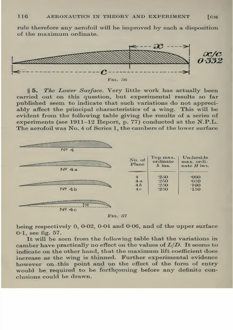
8/13/2019 Aeronautics in the 00 Cow Lu of t
http://slidepdf.com/reader/full/aeronautics-in-the-00-cow-lu-of-t 144/365
116 AERONAUTICS IN THEORY AND EXPERIMENT [CH
rule therefore any aerofoil will be improved by such a disposition
of the maximum ordinate.
f^—3C—-H
oc/c
0332
Fig. 56
§ 5. The Lower Surface. Very little work has actually been
carried out on this question, but experimental results so far
published seem to indicate that such variations do not appreci-
ably affect the principal characteristics of a wing. This will be
evident from the following table giving the results of a series of
experiments (see 1911-12 Report, p. 77) conducted at the N.P.L.
The aerofoil was No. 4 of Series 1, the cambers of the lower surface
N9 4
N9 4a
N9 4b
'TTZ'/^mmMm
^^\
No, of
plane
4
4a46
4fi
Top max.
ordinate
h ins.
•250
•250
•250
•250
Underside
max. ordi-
nate R ing.
•000
•050
•100
•150
Fig. 57
being respectively 0, 0-02, 0-04 and 0-06, and of the upper surface
0-1, see fig. 57.
It will be seen from the following table that the variations in
camber have practically no effect on the values of L\T). It seems to

8/13/2019 Aeronautics in the 00 Cow Lu of t
http://slidepdf.com/reader/full/aeronautics-in-the-00-cow-lu-of-t 145/365

8/13/2019 Aeronautics in the 00 Cow Lu of t
http://slidepdf.com/reader/full/aeronautics-in-the-00-cow-lu-of-t 146/365
118 AERONAUTICS IN THEORY AND EXPERIMENT [CH
on the variation of the position of the centre of pressure is of
considerable importance, and will be discussed later in this
chapter (see § 10).
It cannot be repeated too often that although attempts are
always made in aerodynamic investigations to isolate the effects
of any particular modification, the difficulties inherent in achieving
this are always such as to throw doubt on the possibility of
applying the result with rigour.
Fig. 59
2. Variation in Aspect Ratio.
§7. The aspect ratio may be defined as the length of the
span of the wing divided by the chord. That some effect should
be expected by varying this quantity from wing to wing is not
unnatural if it be remembered that the mere fact that the wing
has ends at all will be sufficient to affect the flow, in that regionat least. At some distance from the ends, the flow for all practical
purposes is two-dimensional in a plane parallel to the plane of
symmetry of the machine, but as the wing tips are approached
the effect is to alter this state. The pressure on the under surface
being moderately large, there is a tendency for the air to be
drawn round the tips of wing towards the upper surface where
the pressure is exceedingly low on account of the suction effect
produced there by the motion. The greater the span the less
will this effect be appreciated at some distance from the end,
and the question at issue is whether by varying the span an
increase in this effect or otherwise will operate to increase the
aerodynamic efficiency of the wing.
This question has

8/13/2019 Aeronautics in the 00 Cow Lu of t
http://slidepdf.com/reader/full/aeronautics-in-the-00-cow-lu-of-t 147/365
VI] THE AEROFOIL 119
somewhat similar to Bleriot 11 bis with 4 chord and rectan-
gular form, was tested in the wind channel for values of aspect
ratio ranging from 3 to 8. The results asfar
as they relate to thepresent discussion are tabulated below.
Aspect
ratioMax. LID (-K'j)infix.
L/Dat
3 101 •670 4-75
4 115 •680 515
5 12-9 •685 556 140 •686 5-2
7 151 •689 508 15-5 •686 5.2
The value of the maximum LjD increases rapidly with increase
of aspect ratio and although at 8 to 1 it is still rising, construc-
tional reasons usually operate to limit the extent to which a
designer might use this fact. The LjD at the chosen low lift
coefficient is apparently not affected by change in aspect ratio
to any appreciable extent, and it is not surprising therefore to
find that a high speed machine rarely has an aspect ratio exceeding
4 or 5.
3. Variation in Plan Form.
§ 8. Various attempts have been made to increase the
aerodynamic efficiency of a wing by changing the plan form, but
the advantages obtained are not such as to allow much modifica-
tion for this purpose to take precedence over other considerations.
The plan form may be altered for two reasons, firstly for stability
purposes, and secondly to increase the aerodynamic efficiency. In
certain cases these two factors may operate against each other
in which instance stability takes precedence as for example in the
case of the Taube, but in general stability requirements may be
satisfied by other and simpler means.
Eiffel in his published researches, La Resistance de VAir et
VAviation, p. 144, describes a few investigations conducted on
wings whose plan forms include those of rectangular shape with

8/13/2019 Aeronautics in the 00 Cow Lu of t
http://slidepdf.com/reader/full/aeronautics-in-the-00-cow-lu-of-t 148/365
120 AERONAUTICS IN THEORY AND EXPERIMENT [CH
For purposes of design where experimental results are available
on aerofoils of rectangular plan form the following formulae may
be used to a fair degree of approximation for obtaining the force
coefficients on the same aerofoil with semi-circular tips and faired
so that the sections remain similar.
Lift coefficient rounded tips
= lift coefficient for square tips,
Drag coefficient rounded tips
= Drag coefficient for square tips minus 0-0018/i2,
where R is the aspect ratio.
§ 9, Pressure Distribution round an Aerofoil. As far as the
actual performance of an aerofoil is concerned, all the designer
need know is the magnitude, direction and position of the resultant
force for any angle of attack within the practical flying range, for
on these as a basis all the remaining factors of the machine may
be calculated. In general these facts may be determined with
sufficient accuracy by simple wind channel experiments. There
remain however many points connected with the actual design
of an aerofoil efficient for special purposes which could only be
settled by an accurate knowledge of the manner in which the
various parts contribute by the pressures on them to the resultant
forces. One of the most important of these is the extent to which
the pressures upon the upper and lower surfaces affect the forces
of lift and drag. Such information would immediately throw
light in the direction in which research on the modifications in the
wing form should be conducted.
The experiment, as usually carried out, consists of mounting
an aerofoil in the usual manner in the wind channel. At various
points along a section and along the span of the aerofoil verysmall exploring holes are made each of which is in turn connected
from the inside of the aerofoil to a pressure gauge, and the pressure
measured at a given wind speed and various angles of incidence.
An experimental difficulty essential in the method immediately
presents itself. The mere presence of a hole will be sufficient to
disturb the flow in that region especially if the form of the surface

8/13/2019 Aeronautics in the 00 Cow Lu of t
http://slidepdf.com/reader/full/aeronautics-in-the-00-cow-lu-of-t 149/365
THE AEROFOIL 121
The results of actual experiments of this nature are published
[in the Report of the Advisory Committee for Aeronautics, 1911-12,
p. 85 and 1912-13, p. 103. The wind speed was 17 ft./sec. in theformer case, and 30 ft./sec. in the latter. The method adopted for
measuring the pressure was such as to furnish a direct com-
parison between the pressure at the point under consideration
and the velocity head of the wind, and the pressures actually
tabulated give the differences between the point considered and
the static pressure there when the flow was undisturbed by the
presence of the model.
It is evident that what is measured at each point is merely
the component of the total pressure there normal to the surface,
and therefore cannot include skin friction*. If by this means the
pressures at every point round the aerofoil be obtained and the
resultant force to which these give rise be calculated, it cannot
Fig. 60
contain any component of the surface frictional forces which are
brought into play. The difference between the resultant so
obtained and the total force on the aerofoil as usually measured
in the wind channel consequently furnishes an estimate of the
skin friction.
If P be the pressure as measured in the experiment normal
to a small element hs of the aerofoil inclined at an angle 6 to
OX (fig. 60), then the amount this contributes towards the force
in the direction OY is Phs cos 6 = P x [Ss cos 6) = PSx and

8/13/2019 Aeronautics in the 00 Cow Lu of t
http://slidepdf.com/reader/full/aeronautics-in-the-00-cow-lu-of-t 150/365
122 AERONAUTICS IN THEORY AND EXPERIMENT [cH VI
at each point be plotted on an X base, and the area of the closed
curve—closed since the pressures are measured right round the
aerofoil
—represents the component of the resultant force in thedirection Y. In the same manner by plotting the pressure at each
point on a y base the component of the resultant force in the
direction OX can be found. In the Report (1912-13) already
referred to, OX and OY are taken parallel and normal respectively
to the chord of the aerofoil. Figs. 62 and 63 represent the pressure
(Ibs./sq. ft. -i- pv^) as found by experiment over the central section
of a wing and plotted in the manner described for angles of
incidence — 2° to + 12° for every two degrees. The profile of
the aerofoil used is given in fig. 61.
The areas enclosed by the curves in the first series are pro-
portional to the force per unit length of the aerofoil at the mid-
section normal to the chord, and in the second series parallel to
Plan of Aero-foil
Fig. 61
the chord. It will be seen by reference to these figures how
greatly the lift (practically normal force) is dependent on the
suctional effect at the upper surface especially in the region of
the leading edge. Between the points 3 and 4 the maximum
ordinate of the aerofoil occurs and it will be at once evident how
greatly the upper surface from there to the nose affects the
question when it is seen that these are the points that correspond
to the region of greatest negative pressure (cf. § 11, Chapter II).
The minor part played by the under surface and the trailing edge

8/13/2019 Aeronautics in the 00 Cow Lu of t
http://slidepdf.com/reader/full/aeronautics-in-the-00-cow-lu-of-t 151/365
—o
V oo
V
<t5
o rt
05
'^^
1>o
erf
Oh 6 o
-2 S
rt
&,
a poO ^
£s«
8/13/2019 Aeronautics in the 00 Cow Lu of t
http://slidepdf.com/reader/full/aeronautics-in-the-00-cow-lu-of-t 152/365
124 AERONAUTICS IN THEORY AND EXPERIMENT [cH VI
section and expressed in absolute units, are plotted, fig. 64, at
each section for lift and drag. It will be seen that the mid-
section A is by far the most efficient while D close to the wing tip
is the least.
The effect of the tip apparently is to reduce the lifting power
in that region and the bearing of this on the question of large
aspect ratio is extremely illuminating in view of the conclusions
already arrived at in § 7. It may be remarked in passing, that
the results in figs. 62 and 63 are of importance to the designer
for purposes of strength of construction as giving the distribution
of force along the wing.
Since the ordinate at any point on one of these curves repre-
sents the lift or drag, omitting skin friction, for the corresponding
section and angle of incidence, the component of lift and drag
due to wind pressure as distinguished from skin friction will be
represented by the area of each of these curves. These divided
by half the span are plotted in fig. 65, giving lift, drag and L/D
for various angles of incidence. On the same diagrams the
experimental values of these forces as found directly in the wind
channel are plotted for comparison. The two curves for lift
coincide. The drag on the other hand for angles of incidence
greater than 0° is greater in the case of the ordinary force experi-
ment, the difference between the two ordinates giving a measureof the skin friction. For negative angles of incidence the curious
result appears that the skin friction is in the opposite direction.
The aerodynamical possibility of this has already been referred
to in Chapter II, § 12.
§ 10. Centre of Pressure. The forces which are brought into
play on an aerofoil will be completely determined when their
positions and magnitudes are known. It is of course evident
that the resultant force at any time does not act at a definite
point but along a definite line, and so long as it is possible to
fix some point on that line, when the components of the force
are given, everything will be known regarding that force. It is
aeronautical

8/13/2019 Aeronautics in the 00 Cow Lu of t
http://slidepdf.com/reader/full/aeronautics-in-the-00-cow-lu-of-t 153/365
d^pg Su/pedj ujojj. pjoqj jo uoi/ioeuj
00 to -^ Nl oo o o o6660

8/13/2019 Aeronautics in the 00 Cow Lu of t
http://slidepdf.com/reader/full/aeronautics-in-the-00-cow-lu-of-t 154/365
1( J
1
0)
b
«4- \\
c
oK
r
L/
JC-
T
^?^
^^-=:====^=^®^^
^'^^
^D?4
-^^%«. 00
e
^'^^
^S.
lD
O\^
bl
/
.^^3 u) ^t< (< ^^ r^ c>l
t;
.r§c; t.
<ijQ;
.^ ii
II^-^
.t; lO
SCD
^ o@ e
c:
.$03 ;^<J <t
s^^h'S
§•5
<fe<.^
ilc;.'
^^
NjSol

8/13/2019 Aeronautics in the 00 Cow Lu of t
http://slidepdf.com/reader/full/aeronautics-in-the-00-cow-lu-of-t 155/365
jH Vl] THE AEROFOIL 127
the position of the resultant force by giving its components
two directions (lift and drag) and the moment about some point,
say the nose of the aerofoil, by which method indeed the centre
of pressure is usually determined. It has however become the
standard custom to discuss the question in terms of the centre of
pressure as already defined.
Since the air forces on an aerofoil depend on the angle of
attack in magnitude, position and direction, the position of the
centre of pressure will vary correspondingly, and it is of extreme
importance in questions of stability, and in predicting the per-
formance of the machine generally, to know exactly how these
variations take place. In particular the relation of such changes
to the centre of gravity of the machine is of special significance,
for upon this depends the question as to whether a change in
angle of attack, when flying, will bring into operation moments
about the centre of gravity tending to disturb equilibrium. Ashift of the resultant force from one side to the other of the centre
of gravity would change the sign of the moment, and if the centre
of gravity lies in the neighbourhood of the centre of pressure a
slight shift of this nature producing as it would considerable
changes in the value of this moment might have important
consequences. On general grounds it can be easily seen that a shift
of the centre of pressure towards the nose of the aerofoil with
increasing angle of attack would tend towards instability, for, in
normal flight, the resultant force is practically equal to the weight
of the machine, and a shift of this resultant force forward caused
by an increase in angle of attack would therefore at once bring
into play a couple tending still further to increase this angle.
Unless such a change of attitude immediately gives rise to new
restoring moments of the proper amount on other parts of the
machine, for example the tail plane, a state of instability would
result. It is necessary therefore to have accurate knowledge as
to within what limits the centre of pressure may be expected
to change its position under altered circumstances. A certain
amount of such change in position may even be a desirable feature.

8/13/2019 Aeronautics in the 00 Cow Lu of t
http://slidepdf.com/reader/full/aeronautics-in-the-00-cow-lu-of-t 156/365
128 AERONAUTICS IN THEORY AND EXPERIMENT [CH
resultant force V(^^ + ^^)^ ^^^ leverage of the moment is found
and this fixes the point where the resultant force intersects the
chord, i.e. the centre of pressure. Fig. 66 gives the position ofthe
centre of pressure for aerofoils r.a.f. 3, r.a.f. 6, and four modifica-
tions of R.A.F. 6, obtained by reversing the curvature of its trailing
edge as already indicated in § 6. A glance at this figure shows at
once that a reversal of curvature tends to drive the centre of
pressure back towards the trailing edge with increase of angle of
attack, and this as already pointed out is a desirable feature. The
Centre of Pressure.
Leading Edge
0-Z ^ 0-3 0-4
Lift Coefficient.
Fig. 66
Trailing\Ed^e
authors would like once more to emphasise the further suitability
of such an aerofoil for high speed machines from the point of view
here under discussion.
Aerofoil Combination.
§ 11. Biplane. In the attempt to increase the wing area in
order to obtain the greatest lift out of an aerofoil it was found

8/13/2019 Aeronautics in the 00 Cow Lu of t
http://slidepdf.com/reader/full/aeronautics-in-the-00-cow-lu-of-t 157/365
VI] THE AEROFOIL 129
method of using aerofoils in a biplane is desirable in the first place
from the fact that, with a smaller loss in the necessary weight of
[construction, extra wing area may thus be obtained.
It is evident that the results obtained for aerofoils when
tested in the wind channel singly cannot, without some modifica-
tion, be applied to a biplane on account of interference effects.
Such questions must be the subject of special experimental
investigation, but what is the principal concern for the present
discussionis
how toutilise
thisinterference in such a
manneras
to increase the efficiency of the combination. It is found in the
first place that the wings of the upper and of the lower plane are
not by any means equally efficient. The experimental method
adopted to investigate these questions is to test each plane
Fig. 67
separately in the wind channel with the other placed as it would be
relative to it in a biplane. These indicate that the interference
is such as to cause the upper plane to be more efficient than the
lower, but the combination is less so, than a single plane of the
same total area. Itis
advantageousto divide the total wing area
between the two planes in such a way as to increase that of the
more efficient wing and accordingly the upper plane has usually
a greater span. Any alteration in the relative positions of the
two planes will involve a corresponding change in this inter-
ference effect.

8/13/2019 Aeronautics in the 00 Cow Lu of t
http://slidepdf.com/reader/full/aeronautics-in-the-00-cow-lu-of-t 158/365
130 AERONAUTICS IN THEORY AND EXPERIMENT [CH
already been stated that in the region behind and above the
aerofoil, the pressure is lower than at other points and conse-
quently it is to be expected that when the relative position of thetwo planes is such as to involve a portion of the under surface of
the upper plane in the region so formed by the lower plane, see
6', fig. 67, the lift would be diminished. A positive stagger may be
expected to yield an advantage; it remains for experiment to
0-50
0-45
^0-40
I^0-35
.§ 0-30
§0-25
5 0-20
*§0-15
0-10
0-05
0-00
0-4^ Q;
/^38
/
/A
7
^^
//7
A//
/i
// m »
•o
-2 2 4 6 8 10
Inclination of Chord to Wind (Degrees)Fig. 68
12
determine the amount. The effect of such a modification has been
investigated at the N.P.L. and published in Report 60, Advisory
Committee for Aeronautics, 1911-12. In these experiments the
perpendicular distance between the two planes was 5 and equal
to the chords of the planes, and tests were made when the amount

8/13/2019 Aeronautics in the 00 Cow Lu of t
http://slidepdf.com/reader/full/aeronautics-in-the-00-cow-lu-of-t 159/365
THE AEROFOIL 131
advantage in setting the upper plane in advance of the lower.
An improvement in 5 per cent, from 82 to 86 per cent, of the
single plane being obtained on the L and LjD when the upper
is ahead of the lower plane by 04 of the chord.
For many purposes, especially of a military nature, a positive
stagger brings another advantage in its train. The pilot or
observer usually occupies a position just above the lower plane
Inclination of Cliord to Wind {Degrees}
Fig. 69
and the fact that this lower wing is thrown back extends to him
a wider range of vision. For warding off an attack or for observa-
tion purposes generally, this is of vital importance. Apart from
the advantages enumerated above, stagger involves distinct

8/13/2019 Aeronautics in the 00 Cow Lu of t
http://slidepdf.com/reader/full/aeronautics-in-the-00-cow-lu-of-t 160/365
132 AERONAUTICS IN THEORY AND EXPERIMENT CH
evident that the biplane may be made to function as two single
planes if the gap be sufficiently increased, but constructional and
allied considerations make it more desirable to diminish the gapas far as possible. In the Report referred to in § 12 the effect
of a change in gap from 0-4 to 1-6 is described. The results given
in the diagrams, figs. 70 and 71, show that the lift coefficient at a
given inclination is considerably less in a biplane than in a mono-
plane. There is a corresponding fall in drag but of smaller amount,
•2 24
6 8 10
Inclination of Chord to Wind (Decrees)
Fig. 70
12
so that the LjD is not so much affected as the lift itself. The curve
also indicates the considerable remaining effect when the gap is
equal to the chord. The normal practice is to take gap as here
defined equal to 1-1.

8/13/2019 Aeronautics in the 00 Cow Lu of t
http://slidepdf.com/reader/full/aeronautics-in-the-00-cow-lu-of-t 161/365
THE AEROFOIL 133
then if Ki , Ka be the coefficients at gap/chord = unity
^and Ki' , Ka
for biplane
and for triplane
K/ = K, (1 + 0'2g),
K^ = Ka+ 0'22g (K^ - 0-014),
K,' = Z, (1 + O-S^r),
KJ = Ka-{-0-29g{Ka-0'01Q).
-2 2 4 6 8 10
Inclination of Chord to Wind (Degrees)
Fig. 71
12,
§ 14. Triplane. Serious attempts have been made, in the
desire to obtain more wing area and therefore greater lifting
capacity, to arrange the aerofoils in triplane fashion, for already,

8/13/2019 Aeronautics in the 00 Cow Lu of t
http://slidepdf.com/reader/full/aeronautics-in-the-00-cow-lu-of-t 162/365
134 AERONAUTICS IN THEORY AND EXPERIMENT [CH
J. C. Hunsaker, and the results of the latter published in Efigi-
neering, July, 1916.
The triplane apparently is not so efficient as the biplane anddemands considerably more engine power, but granting this it is
capable of supporting nearly the same weight for the same wing
area at the position of maximum lift.
Experiments conducted at the above institution to discover
the distribution of load upon the three wings of a triplane (r.a.f. 6)
show that the upper wing is by far the most effective of the three,
and the middle wing the least. This is brought out in the following
table, where the gap =1-2 times the chord length and there was no
stagger.
Angle of Lift, Lift, Lift, LID, LjD, LjD,Incidence upper middle lower upper middle lower
0° 2-68 1-0 1-82 3-63 10 2-302° 2-14 1-0 1-76 318 10 2134° 1-91 1-0 1-64 2-59 10 1-69
8° 1-56 1-0 1-36 1-49 10 1-37
12° 1-56 1-0 1-31 1-30 10 1-34
16° 1-49 1-0 1-20 1-22 10 117
Aspect ratio of each plane 6-3.
Chord 2-5 .
Wind speed 30 m.p.h.
The efficiency of the combination was tested by a comparison
with monoplanes and biplanes with the same wing sections (gap
of biplane 1-2 of chord), and the following table of the more
characteristic points indicates the relative importance of the
coefficients in these cases. The monoplane was taken as standard
and the biplane and triplane coefficients expressed as a percentage
of those of the former.
Angle ofMono plane Biplane Triplane
IncidenceLift LjD Lift LID Lift LID

8/13/2019 Aeronautics in the 00 Cow Lu of t
http://slidepdf.com/reader/full/aeronautics-in-the-00-cow-lu-of-t 163/365
VI] THE AEROFOIL 135
t, 'f.\
r-i
\ \
',\ g-
\\\ \
\ \\ e
\
\
\
\
\
o
\\\ \
t^
\ V
o
\\
\\
\
(\3\ \ *
i\
<0\\«. 4iX
c\ - k_
i\\
- ^^ ^
VA V
\. w 2|V \
\ \^1
1VV
\ .1
\o
-?^^doiIW 7 dui?ldouQi/^•>
^lAl/%U91C M^ ^ohA
-A
CO
61
O1
c
c
C:5'\
o1
w

8/13/2019 Aeronautics in the 00 Cow Lu of t
http://slidepdf.com/reader/full/aeronautics-in-the-00-cow-lu-of-t 164/365
136 AERONAUTICS IN THEORY AND EXPERIMENT [CH
The maximum lift of the triplane is accordingly almost
great as that of the biplane but
the LjDis less.
The results seemto indicate that there is a field for
fruitful research in this direction
and this has been borne out by
the excellent performances of tri-
planes recently constructed.
§ 15. Biplane and TriplaneCorrections from Monoplane. In
the design of a biplane or a tri-
plane it is always desirable if
possible to obtain the results of
tests on the corresponding model,
but where these are not available
the results plotted in figs. 72 a
and 72 h may be taken as re-
presenting to considerable ac-
curacy the corrections that must
be applied to the results for the
monoplane wing in order to
furnish the corresponding quan-
tities for the biplane or triplane.
The figures are self-explanatory.
The position of the centre of
pressure for such combinations
does not appear appreciably
altered from that of the mono-
plane if in these cases it is
measured with reference to the
main plane and plotted against
lift coefficient.
Scale Effect.
§ 16. In a previous chapter
as
,' J/
41I6
t^
o
jl
j
1 1
/ 1
/ 1
6-^
f i
'
1
1
1
1°l
1
1
^
°^1
1
I °l]
\r-»
\o\
\
\\
c-
c
^ r
5 c

8/13/2019 Aeronautics in the 00 Cow Lu of t
http://slidepdf.com/reader/full/aeronautics-in-the-00-cow-lu-of-t 165/365
fvi] THE AEROFOIL 137
that for two bodies of different dimensions tlie forces brought
into play upon them will be equal when the experiments are
carried out at the same vahie of VL. Unfortunately, however,
two factors at least operate to prevent a complete and direct
comparison. In the first place if an experiment on a model
aerofoil be carried out at the VL corresponding to the normal
flight speed of a full scale wing, the forces that would require
measurement—the ordinary forces in flight—would be too great
for the apparatus of wind channel work. In the second place,
even if this measurement were possible, the dimensions of an
ordinary wind channel and the speed of wind there attainable do
not give a VL of more than about one-tenth that occurring
under usual flying conditions. It becomes necessary, therefore, to
consider how the various characteristics of an aerofoil vary with
increasing VL and if possible from these results to extrapolate
to the values required under flying conditions. As a matter offact the correction that is required in passing from experi-
mental results obtained say in the 7' channel at the highest VL
to full scale is comparatively small, and after a little experience
can be predicted with considerable precision.
Certain characteristics are scarcely affected at all by the
passage beyond a certain point to larger values of VL, as for
example the maximum Hft coefficient and the angle at which it
occurs. On the other hand the maximum L/D receives a con-
siderable increase while the angle of no lift reaches a slightly
greater negative value than for the experimental scale. It was
seen previously in Chapter IV that certain values of VL repre-
sented the point of transition from one type of flow to another
and were therefore critical. If it should happen that the VL for
the model experiment lies in the region of this point of transition
certain characteristics will occur in the model curves which by
the passage to higher values of VL should be eliminated. This
in point of fact does occur.
Experimentally, the method generally adopted is to carry out
the investigation on the model to as large values of VL as possible

8/13/2019 Aeronautics in the 00 Cow Lu of t
http://slidepdf.com/reader/full/aeronautics-in-the-00-cow-lu-of-t 166/365
138 AERONAUTICS IN THEORY AND EXPERIMENT [CH
a log VL base instead of VL as this extends the region on the
graph for the smaller values of VL investigated, and contracts
the unknown region for larger values. A base IjVL would also
be convenient for this purpose.
0-6
4 6 8 10 12 14
Angle of Incidence (Degrees)
Fig. 73
20
A
//////
4r.^yV/ ///
^' / n
// /
/ / 20^.///lOft./sec.// 1^
76^^^^^(Vsoft/sec.
^^^
_^^^^^^^^
2 (3 Ji it A3 . i3 .1P 1Z 1-i. 1 & 1B 2
Angle of Incidence (Degrees)
Fig. 74

8/13/2019 Aeronautics in the 00 Cow Lu of t
http://slidepdf.com/reader/full/aeronautics-in-the-00-cow-lu-of-t 167/365
VI] THE AEROFOIL 139
of R.A.F. 6 aerofoil is described and the variation of lift and drag
coefficients with increase in VL is investigated. The aerofoil was
tested for inclinations of the chord to the wind varying from
- 2° to + 20° and for values of VL from 2-1 to 104, where V is
the wind speed in ft./sec. and L the chord of the aerofoil in feet.
The variations of the lift and drag coefficients with angle of
incidence for the different values of VL are given in figs. 73 and 74.
These sliow the existence of distinct variations in these coefficients
with VL, the most marked occurring in the value of the drag. The
lift coefficients for a given inclination appear to tend to a limiting
value, namely that measured at the highest speed obtainable in
20
15
SlO
1
r^
-^4^•^To°^
^ySi
3
^1
to
30-5 1-0 1-5
Log VL
2-0 2-5 3-0
Variation of Lift/Drag with VLL=length of chord in feet
F = velocity in feet per sec.
Fig. 75
the channel. Unfortunately the range of VL is not sufficiently
great for a precise prediction of the drag on a full scale aerofoil
to be determined. To remedy this a comparison was made with
tests on full scale aerofoils carried out at the Institute Aero-

8/13/2019 Aeronautics in the 00 Cow Lu of t
http://slidepdf.com/reader/full/aeronautics-in-the-00-cow-lu-of-t 168/365
140 AERONAUTICS IN THEORY AND EXPERIMENT [CH
the steady full scale value, and the error involved in extrapolating
is not considerable. The curves in fig. 76, obtained from the same
results, assuming a landing speed unity for the machine, show howthe performance curve varies with scale. The dotted curve,
estimated from the full scale results already referred to, gives the
limit to which they tend. The annexed table may serve as a guide
to such correction.
1-0 1-1 1-2 1-3 1-4 1-5 1-6 1-7
Speed Ratio.
Fig. 76
1-8 1-9
The curves given here may be considered as furnishing con-
version factors from which the LjD of a full scale aerofoil may
be estimated from wind channel experiments on models. Accurate

8/13/2019 Aeronautics in the 00 Cow Lu of t
http://slidepdf.com/reader/full/aeronautics-in-the-00-cow-lu-of-t 169/365
VI THE AEROFOIL 141
§ 17. Corrections to he applied to the results of model experi-
ments to convert into the correspondingfull scale measurements.
AerofoilValue
of VLMax.
L/D
Angle at
which
max. L/Doccurs
Max. lift
coefficient
Angle
at no
lift
Angle
at max.
lift
R.A.F. 6
Full scale
10
500
16-6
190
39°30°
0-6
0-6
-2°
-2-8°
.5»
15°
Deduxitionsfrom above table.
Increase maximum LjD by 15 per cent.
Diminish angle at which maximum LjD occurs by 20 per
Add to the angle of no lift — -8°.
Do not alter the angle of maximum lift coefficient nor the
(a)
(b)
cent.
(c)
value of this lift coefficient.

8/13/2019 Aeronautics in the 00 Cow Lu of t
http://slidepdf.com/reader/full/aeronautics-in-the-00-cow-lu-of-t 170/365
CHAPTER VII
STRUCTURAL PARTS AND CONTROLS
§ 1. Every part of the macliine in its motion coming into
contact more or less direct with the air is acted upon by forces
which will operate in some measure upon the motion. Certain
of these surfaces exist and are designed purely in view of the fact
that these forces are originated. This is the case for example
both with the propeller and the wings. Controlling surfaces on the
other hand, the tail plane and the rudder among others, owe their
existence, their position and their dimensions to the fact that only
under certain circumstances air forces of a specific type may be
brought into being. There is another class of surface which does
not fall within either of these categories. Such bodies as struts
and wires whose functions are not in any sense aerodynamic, but
are essentially required for the furnishing of strength to the
machine regarded as a structure, nevertheless give rise to resisting
forces which are not otherwise contemplated. From the point of
view of the aerodynamic forces brought into play during flight,
these various classes, as will be seen, practically include all the
external portions of the machine, but there does not exist any clear
line of demarcation between these several groups. A propeller
whose sole function is to provide a forward thrust cannot do so
without discharging the air behind it in a comparatively sharply
defined stream. If the air propeller be fixed in front as in the case
of a tractor machine, this discharged air or slip stream acting upon
the parts such as the body and wings immediately in its rear
disturbs the flow and modifies the forces upon them. These
so-called interference effects are clearly necessarily inherent in any

8/13/2019 Aeronautics in the 00 Cow Lu of t
http://slidepdf.com/reader/full/aeronautics-in-the-00-cow-lu-of-t 171/365
CH VII STRUCTURAL PARTS AND CONTROLS 143
except in so far as they give rise to interference effects, and to
discover how these forces can be utilised to fulfil the aerodynamic
functions, if any, for which they exist. Generally it may be stated
as a fundamental principle in design that these surfaces should be
so shaped as to provide the minimum sum total of resisting forces
foreign to their function.
§ 2. For simplicity in study it will be convenient to consider
for the present two of these groups only.
(a) Those parts that exist purely for constructional reasons
but which also incidentally offer resistance to the forward motion.
1. The body and fuselage or outrigger.
2. The struts and wires.
3. The undercarriage.
4. The propeller when not driven by the engine.
(6) Those parts that exist for the purpose of providingguidance and stability to the machine—classified generally as
controlUng and stabilising surfaces.
Controls.
1. Eudder.
2. Elevator.
3. Wing-flaps.
Stabilising surfaces,
4. Tail plane.
5. Fins proper and equivalent fins.
Parts existing for Constuctional Reasons but offering
Resistance to Forward Motion
§ 3. The Body and Fuselage. The function of the body is
to provide seating accommodation for the pilot and passengers,
room for the instruments necessary in the determination of speed,
height and climb, and a solid basis for the engine. The fuselage
connecting the body and the tail system exists purely to provide

8/13/2019 Aeronautics in the 00 Cow Lu of t
http://slidepdf.com/reader/full/aeronautics-in-the-00-cow-lu-of-t 172/365
144 AERONAUTICS IN THEORY AND EXPERIMENT [CH
of stream-lining entered into in Chapter II, it will be clear that
generally the most suitable shape will be one with a comparatively
Drift
<^FltchingMoment
^' i^i;
Model B.E. 2.
Fia. 77
Model B.E. 3.

8/13/2019 Aeronautics in the 00 Cow Lu of t
http://slidepdf.com/reader/full/aeronautics-in-the-00-cow-lu-of-t 173/365
ivn] STRUCTURAL PARTS AND CONTROLS 145
operates simultaneously to diminish the resistance of the whole.
To determine a good shape for the body, on the other hand,
serious difficulties have to be faced. In the case of a tractor,
where the propeller is situated in front, the engine occupies the
nose of the body, and since for the sake of cooling it must not be
.ri^^^lABcrrr:^:^
0-309'
^SBModel 4.
Fig. 79
^...•5^4^^^-
completely enclosed, good stream-lining is made impossible. A

8/13/2019 Aeronautics in the 00 Cow Lu of t
http://slidepdf.com/reader/full/aeronautics-in-the-00-cow-lu-of-t 174/365
146 AERONAUTICS IN THEORY AND EXPERIMENT [CH
Committee for Aeronautics, 1912-13, p. 121. The results are given
in the following table for the full size bodies.
BodyDrag at 60 m.p.h.
in normal flight
(lbs.)
Drag (length )2
B.E. 2
B.E. 3
Model 4
Model 5
54025-8
35-3
18-4
010200410-080
0-054
The above are without rudder or elevating planes.
For bodies of the same length the above shows that the B.E. 3
body is by far the best form, its drag being less than half that of
the B.E. 2.
It must be noted to the disadvantage of the tractor that the
existence of the propeller in front of the body necessitates the
latter lying directly in the slip stream. The velocity of outflow
from the propeller is considerably greater than that of the machine
relative to the air as a whole and consequently the resistance of
the body is greater than would otherwise be the case. At the
same time, experience has shown that the existence of the body
in the slip stream tends to increase the efficiency of the propeller.
It follows that these two portions of the machine ought not to be
considered separately but rather their efficiency as a combination.
The pusher type of machine, on the other hand, having the
propeller behind, necessitates a short tail, since the fuselage no
longer exists, but is replaced by an outrigger, and the
resistance of the body is thereby increased. The existence
of the body in front has been found, in many cases, to
increase the efficiency of the air-screw slightly, but never to
the same extent as in the case of the tractor. Further experi-
mental evidence, however, on these points from the aspect of
efficiency of combination of body and propeller would require to
be forthcoming before the above conclusions can be regarded as
thoroughly substantiated.

8/13/2019 Aeronautics in the 00 Cow Lu of t
http://slidepdf.com/reader/full/aeronautics-in-the-00-cow-lu-of-t 175/365

8/13/2019 Aeronautics in the 00 Cow Lu of t
http://slidepdf.com/reader/full/aeronautics-in-the-00-cow-lu-of-t 176/365
148 AERONAUTICS IN THEORY AND EXPERIMENT [CH
a centre piece to take the load and the stream-lining effected by
a fabric cover fastened in position by wooden ribs to give the
requisite shape.
In practice a considerable amount of trouble arises owing to
the failure of wires under vibration. Experiments which have
been conducted to determine whether the resistance is increased
by such motion have so far failed to detect any effect. An analysis
of the forces that come into play during vibration is interesting
from the fact that these are often such as to render the motion
unstable and consequently maintain the vibration and even
increase its amplitude. A lateral motion of this nature during
flight is equivalent to an alteration in angle of incidence of the
relative wind, and in such a position the lateral component or
cross wind force may act in the direction of the motion of the wire.
In this connection it may be remarked that in the case of most
wires inclined at an angle of yaw to the wind the cross wind force
is oppositely directed to what might be expected from the corre-
sponding case of a flat plate.
§ 5. Undercarriage and Skid. The principles regarding stream-
lining apply with equal force to all parts of the undercarriage
that come into contact with the air. It is found that the resistance
of the wheels is considerably decreased by covering the disc with
fabric.
§ 6. Propeller. When not driven by the engine the propeller
on account of its awkward shape offers considerable resistance
to forward motion. Fig. 125, Chapter XI, shows the variation in
drag on the machine with forward velocity both with and (gliding)
without propeller. It will be seen in a later chapter that the effect
of this increased resistance is to decrease the gliding angle. This
source of trouble is of course quite unavoidable.
Parts existing for providing Guidance and Stability
7. Controlling following
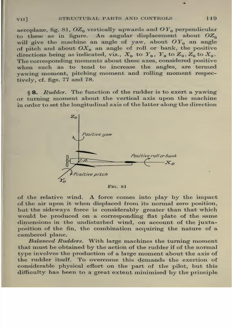
8/13/2019 Aeronautics in the 00 Cow Lu of t
http://slidepdf.com/reader/full/aeronautics-in-the-00-cow-lu-of-t 177/365
VI l] STRUCTURAL PARTS AND CONTROLS 149
aeroplane, fig. 81, OZq vertically upwards and OYq perpendicular
to these as in figure. An angular displacement about OZq
will give the machine an angle of yaw, about OYq an angle
of pitch and about OXq an angle of roll or bank, the positive
directions being as indicated, viz., Xq to Yq, Yq to Zq,Zq to Xq.
The corresponding moments about these axes, considered positive
when such as to tend to increase the angles, are termed
yawing moment, pitching moment and rolling moment respec-
tively, cf. figs. 77 and 78.
§ 8. Rudder. The function of the rudder is to exert a yawing
or turning moment about the vertical axis upon the machine
in order to set the longitudinal axis of the latter along the direction
v^Positi\/eyaw
Positive rollorbank
Xo
of the relative wind. A force comes into play by the impact
of the air upon it when displaced from its normal zero position,
but the sideways force is considerably greater than that which
would be produced on a corresponding flat plate of the same
dimensions in the undisturbed wind, on account of the juxta-
position of the fin, the combination acquiring the nature of a
cambered plane.
Balanced Rudders. With large machines the turning moment

8/13/2019 Aeronautics in the 00 Cow Lu of t
http://slidepdf.com/reader/full/aeronautics-in-the-00-cow-lu-of-t 178/365
150 AERONAUTICS IN THEORY AND EXPERIMENT [CH
of balancing. The method is to arrange a portion of the
rudder A, as in fig. 82, to be just above the fin, the axis being
between this portion and the rudder proper. By this meansthe moment about the axis of the rudder, the strain of which
has normally to be borne by the pilot, is reduced by the
opposing moment due to A.
Limitations in Balancing. The extent to which balancing
may be utilised to assist the pilot to obtain the necessary de-
flection without over-exertion is from one point of view subject
to a serious restriction. If the moment about the hinge be plotted
against the angle of deflection of the rudder, fig. 83, a curve of
the type OB is normally obtained, being the origin, so that if
Fig. 82
OA represents the moment the pilot is capable of exerting, OL will
represent the deflection he can secure. By balancing in the mannerindicated the moment to obtain a given deflection is reduced and
a curve of the type OC obtained, where OM now represents the
deflection for the moment OA. At the rudder is in equilibrium,
the moment being zero, and along OC the moment is such as to
oppose any deflection. Under these circumstances the zero position
is one of equilibrium and of stability. The limiting curve of the

8/13/2019 Aeronautics in the 00 Cow Lu of t
http://slidepdf.com/reader/full/aeronautics-in-the-00-cow-lu-of-t 179/365
VIl] STRUCTURAL PARTS AND CONTROLS 151
be of the type E'F'OFED. Here is a position of instability,
since when the rudder is in normal position the moments caused
by a slight deflection are such as to increase the latter, which is
evidently an undesirable feature.
§ 9. Elevators. The elevator is capable of rotation about an
axis perpendicular to the symmetrical plane of the machine, and
as such can be utilised for effecting an alteration in the value of
the pitching moment on the aeroplane. There are two functions
which the elevator may be called upon to fulfil in virtue of this
fact. It may be used in the first place for correcting any small
variation in angle of pitch by introducing by the appropriate
deflection a pitching moment in the requisite direction. It is, in
Fig. 83
the second place, the most effective means of regulating the speed
of flight, for an adjustment of the elevator will cause an alteration
of the pitching moment on the machine and accordingly its
attitude will alter until a position of equilibrium is reached where
the total pitching moment is zero. This will of course occur at a
special value of the forward speed. The setting of the elevator
thus determines the speed of flight. As in the case of the combina-
tion of fin and rudder so the tail plane and elevator pertain to the

8/13/2019 Aeronautics in the 00 Cow Lu of t
http://slidepdf.com/reader/full/aeronautics-in-the-00-cow-lu-of-t 180/365
152 AERONAUTICS IN THEORY AND EXPERIMENT [cH
considerable effort requires to be exerted continuously by the
pilot to maintain the control in its appropriate position. At the
same time it is necessary to allow him a certain amount of further
play with the elevator for correcting in each of these positions
small variations in pitch. Two methods have been adopted in face
of this difficulty. In the first place the elevator has been balanced
in a similar manner to that effected with the rudder, but as before
limitations are imposed on the extent to which this may be
utilised. In addition it must be remembered that although the
balancing may be effective at one angle of attack it will notnecessarily be so for all. This difficulty does not arise to the same
extent in the case of the rudder. In the second place the function
of the elevator to fix the speed of ffight has been transferred to the
tail plane by making the latter adjustable, and the elevator
proper has been reserved purely for the purpose of eliminating
small fluctuations in pitch.
§ 10. Wing Flaps. The purpose of the wing flaps is to intro-
duce a moment tending to turn the machine about the longitudinal
axis OX, thus originating the angle of bank required for circular
flight or for correcting an accidental roll. A setting of this control
corresponds to a downward deflection of the wing flaps on one
side of the machine and an upward deflection of those on the other,
producing an increased lift on the one wing and a decreased lift
on the other. The same considerations adduced in the case of
rudder and elevator with regard to balancing apply equally
here.
Since the function of the aileron or wing flap is to produce
a rolling moment about the longitudinal axis of the machine, the
efficiency of this part for a particular angle setting may be
regarded as the ratio of the rolling moment produced to the
moment about the hinge of the aileron. The latter is the moment
that must be exerted by the pilot. Using this definition of
efficiency, it is found experimentally that the ailerons are most
efficient near their undeflected position falling off gradually with
increasing angle until at about 15° the efficiency suddenly dimin-

8/13/2019 Aeronautics in the 00 Cow Lu of t
http://slidepdf.com/reader/full/aeronautics-in-the-00-cow-lu-of-t 181/365
VIl] STRUCTURAL PARTS AND CONTROLS 153
figures may be taken as a guide within the range of angle of
aileron + 12° to - 12°.
Angle of Incidence
(degrees)
Rolling Moment CoeflFt.
per degree aileron
deflection
Hinge Moment Coefft.
per degree
deflection
0°
8°
16°
001640-0172
00126
0-00104
0-00084
0-00084
where rolling moment coefficient =
hinge moment coefficient =
where S = span of biplane,
A = total area of ailerons,
C = chord,
L = rolling moment,
H = hinge moment.
LlpASv\
H/pACv^
Stabilising Surfaces
§ 11. Tail Plane. When the aeroplane has communicated
to it a positive angle of pitch, the tail plane lowers and meets
the oncoming air and by the interaction brings into being a
negative restoring moment tending to right the machine. Fora more accurate and detailed discussion of the operation of this
stabilising surface the student is referred to Chapter XII. The
action of the tail is materially affected by the downward current
of air deflected from the main planes. In effect this deflected
current is equivalent to an altered angle of attack of the tail plane.
Experimentally it is found that the so-called angle of downwash
or inclination of the relative wind at the tail to the direction of the
wind relative to the machine is equal to half the angle of attack of
the main planes measured from the position of no lift.
§ 12. Fins and Equivalent Fins. Just as the tail plane
existed for the purpose of introducing a restoring moment when

8/13/2019 Aeronautics in the 00 Cow Lu of t
http://slidepdf.com/reader/full/aeronautics-in-the-00-cow-lu-of-t 182/365
154 AERONAUTICS IN THEORY AND EXPERIMENT [CH
the fin proper can be determined. It will be seen in a later chapter
that too large a fin area unfortunately operates to produce a
particular type of instability. Any part of the machine which hasa cross-section of moderate size with regard to the relative wind
originated during the production of an angle of yaw will act as a fin
by introducing a restoring or disturbing moment roughly propor-
tional to the product of its equivalent cross-section and its
distance from the axis of yaw. The main parts of the machine
which function in this manner apart from the fin itself are (1) body
and undercarriage, (2) dihedral angle of wings, (3) propeller. In
the undercarriage it is chiefly in the wheels covered in by canvas
that fin effect is experienced.
By the dihedral angle (=2/3) is usually understood the
difference between the angle contained by the wings and two right
angles. As a fin the dihedral angle operates in a comparatively
Z
X-2p-Dihedral Angle
Front view of wings.
Fig. 84
tJ_ y^ 'Horizontdl'
complicated manner. If the machine be yawed through an angle
j/f the angle of attack is increased by i/j sin. ^ on one wing and
diminished on the other by the same amount. There results an
increased lift and drag on the first wing and the converse on the
second. The final effect is thus to produce both a yawing and a
rolling moment so that the equivalent fin may be regarded as
situated in general in the plane of symmetry above the machine
and forward of the centre of gravity. In addition to such effects
being produced by mere angular displacements, rotational
velocities will operate in a similar manner. The question will be
further discussed in the chapter on stability.
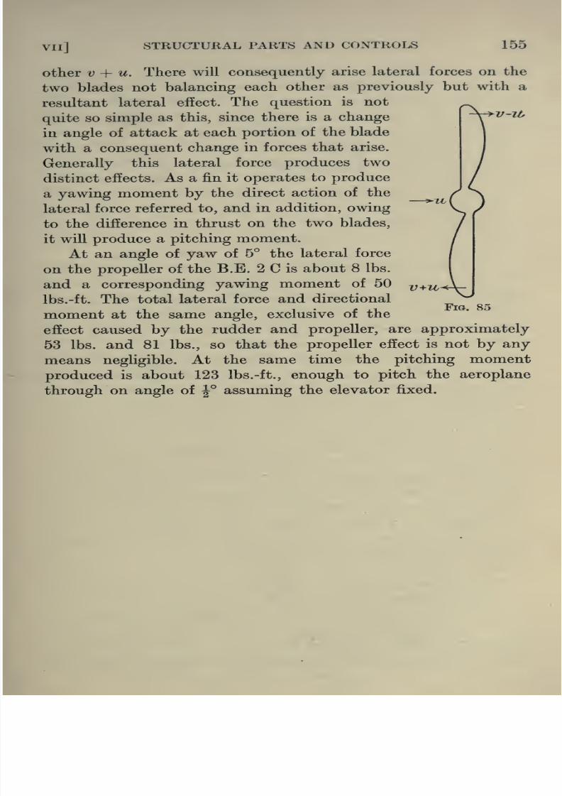
8/13/2019 Aeronautics in the 00 Cow Lu of t
http://slidepdf.com/reader/full/aeronautics-in-the-00-cow-lu-of-t 183/365
VIl] STRUCTURAL PARTS AND CONTROLS 155
v-il,
other V ^- u. There will consequently arise lateral forces on the
two blades not balancing each other as previously but with a
resultant lateral effect. The question is not
quite so simple as this, since there is a change
in angle of attack at each portion of the blade
with a consequent change in forces that arise.
Generally this lateral force produces two
distinct effects. As a fin it operates to produce
a yawing moment by the direct action of the
lateral force referred to, and in addition, owing
to the difference in thrust on the two blades,
it will produce a pitching moment.
At an angle of yaw of 5° the lateral force
on the propeller of the B.E. 2 C is about 8 lbs.
and a corresponding yawing moment of 50
Ibs.-ft. The total lateral force and directional
moment at the same angle, exclusive of the
effect caused by the rudder and propeller, are approximately
53 lbs. and 81 lbs., so that the propeller effect is not by any
means negligible. At the same time the pitching moment
produced is about 123 Ibs.-ft., enough to pitch the aeroplane
through on angle of J° assuming the elevator fixed.
Fig.

8/13/2019 Aeronautics in the 00 Cow Lu of t
http://slidepdf.com/reader/full/aeronautics-in-the-00-cow-lu-of-t 184/365
PART 111
CHAPTER VIII
STRENGTH OF CONSTRUCTION
Analysis of Stress Distribution in Aeroplane
Members
§ 1. The requirements that an aeroplane has to fulfil, especially
in the case of large machines, and those designed for rapid climb,
demand as great economy as possible in dead weight of con-
struction, and only an accurate analysis of the forces brought into
play, and their effects, can indicate where this saving is to be
effected without material weakening of the strength necessary
to withstand the forces of flight. In general for purposes of design
it is not the normal forces of flight that must be considered, but
the maximum forces that the aeroplane may be called upon to
withstand under exceptional circumstances. The greater includes
the less and this ensures that the aeroplane will come safely
through all its manoeuvres.
The stresses that an aeroplane must undergo are due to two
causes, (a) inertia forces, (6) wind forces. In the first class are
included all those which come into existence under the accelera-
tion of the machine or of its parts (engine and propeller) as for
example when starting, stopping and turning. (6) on the other
hand includes such forces as lift and drag on the wings, and load
on the tail. We shall, for the moment, confine our attention
entirely to the forces under the class (6).
§ 2. The maximum wind forces that may normally be called
into play, and those which must for practical purposes be taken

8/13/2019 Aeronautics in the 00 Cow Lu of t
http://slidepdf.com/reader/full/aeronautics-in-the-00-cow-lu-of-t 185/365
CH VIIl] STRENGTH OF CONSTRUCTION 157
increase the load on the tail even to a much greater extent. These
forces will call into existence in the various members of the
structure (spars, struts and wires) tensions and compressions which
each corresponding part must be specially designed to withstand.
•The load on the tail in the same way is distributed through the
longerons, struts and wires in the fuselage, in the case of a tractor,
while in the case of a pusher type in the outrigger. For the present
attention will only be directed to an estimation of the distribution
of the forces and their effects among the members composing
the wing structure and tail system of a biplane.
Nature of external loading due to wind Forces. Forces on Wings.
§ 3. To determine how the external wind pressures affect
the stresses in such an aeroplane member as a wing, it is not
sufficient to know that the load on that member is simply the
resultant wind pressure, but its law of distribution both cross-wise
in the direction of the span, and length-wise in the direction of the
chord must also be known with fair accuracy. For on the nature
of this distribution will depend whether the front or rear portions
are to bear the major part of the load, and which sections of these
front and rear portions will be more heavily stressed.
Reference has already been made, § 9, Ch. VI, to experiments
investigating the distribution in wind pressure over a wing surface.
These experiments have been carried out on models and as already
indicated in the earlier parts of this book must be corrected for
scale effect when applied to the full-size wing. As far as the
present discussion is concerned, however, two considerations
relative to this are worthy of note. In the first place one does not
require to derive the actual values of the wind pressures on a full
scale wing from these model tests but merely their relative values,
for from a knowledge of this and the total load on the wing derived
from considerations of weight the pressure along the span may be
determined. In the second place it is probable that at higher
values of vl than those of the experiment the relative distribution
may alter slightly, but for purposes of stress calculation in-

8/13/2019 Aeronautics in the 00 Cow Lu of t
http://slidepdf.com/reader/full/aeronautics-in-the-00-cow-lu-of-t 186/365
158 AERONAUTICS IN THEORY AND EXPERIMENT [CH
§ 4. Looking at the longitudinal distribution of pressure
(fig. 64, Chapter VI), it is evident that for a wide range in the
vicinity of normal angles of flight the pressure is fairly uniformfrom the centre outwards, but in the region of the tip it falls off
considerably. In determining the stresses in the framework,
therefore, it will be a sufficiently close approximation to the truth
to assume that the distribution in load along the span is constant,
up to a short distance from the tip. From there onwards it is again
supposed constant, but of smaller amount than on the remainder
of the wing. Usually the total normal load is obtained from a
knowledge of the landing speed as explained in Chapter V, and
the distribution by the above method.
These wind pressures acting directly on the fabric of the wing
are transmitted through the ui,
ribs to the two main mem- |J
bers of the wing, the spars, 5
but the extent to which this i^
external loading is distri- ^j
buted between these two
kembers depends entirely r
upon the circumstances ofH'^^^ord-M \
r . H- Olchord- ^night. For purposes of design
where abnormal conditions Fig. 86
must always be considered, there are three principal manoeuvres
which fall to be considered
(a) High speed flight where the angle of attack is usually
very small.
(6) Diving vertically where the normal force on the wings is
practically zero since there is no component of the weight in that
direction. A vertical dive takes place therefore approximately at
the angle of attack for no lift.
(c) Flattening out immediately after a steep dive when the
angle of attack is consequently high.
It is the angle of incidence at which each of these manoeuvres
is executed which determines the distribution of pressure between

8/13/2019 Aeronautics in the 00 Cow Lu of t
http://slidepdf.com/reader/full/aeronautics-in-the-00-cow-lu-of-t 187/365
VIIl] STRENGTH OF CONSTRUCTION 159
fig. 86. In both these cases the direction of the loading is princi-
pally perpendicular to the chord, the longitudinal force being of
practically little consequence. The law of variation of normal force
along the wing is practically the same as that of the Uft given
in fig. 64. In case (b), however, where the lift force is practically
non-existent the loading is almost entirely parallel to the chord,
andmay be assumed for practical purposes constant along the span.
In the case of a biplane account must be taken of the fact that
the upper wing contributes more to the lift than the lower plane.
While practically the same law of distribution in pressure may be
taken in both cases, the component amounts of lift may be taken
from the following table, where the spans of the two wings are
equal.
Ratio of Uft on Plane to total lift of combination.
+ 30° Stagger Zero Stagger -30° Stagger
Angle Upper Lower Upper Lower
?fa^J
Lower
Plane Plane Plane Plane Plane
-6° 0-537 0-463 0-488 0-512 0-429 0-571
-4° 0-504 0-496 0-503 0-497 0-452 0-548
-3° 0-458 0-542 0-513 0-487 0-488 0-512
-2° 0-249 0-751 0-572 0-428 0-476 0-524-1° 0-660 0-340 0-428 0-572 0000 1-000
0-630 0-370 0-510 0-490 0-391 0-609
1° 0-608 0-392 0-482 0-518 0-392 0-608
2° 0-616 0-384 0-514 0-486 0-409 0-591
3° 0-588 0-412 0-505 0-495 0-427 0-573
4° 0-572 0-428 0-510 0-490 0-439 0-541
6° 0-573 0-427 0-513 0-487 0-452 . 0-5488° 0-573 0-427 0-518 0-482 0-457 0-543
10° 0-576 0-424 0-523 0-477 0-459 0-541
12° 0-568 0-432 0-532 0-468 0-497 0-50314° 0-511 0-489 0-532 0-468 0-564 0-436
16° — — 0-498 0-502 0-492 .' 0-508
Analysis of Wing Structure for Stress Distribution.
§ 5. The previous discussion has indicated the nature of the

8/13/2019 Aeronautics in the 00 Cow Lu of t
http://slidepdf.com/reader/full/aeronautics-in-the-00-cow-lu-of-t 188/365
160 AERONAUTICS IN THEORY AND EXPERIMENT [CH
principal members are the spars two in each wing, connected hori-
zontally by ribs a certain definite specified distance apart, and
vertically by gap struts more or less rigidly fixed to the spars. Inaddition to these there exist bracing wires of various types (see
Plate I). In essence this is the rigid structure loaded in a manner
already described which has to be analysed for stress distribution.
In the main each member will be subjected at each point to a
thrust or tension and to a bending moment. It is our object to
indicate how these may be evaluated.
At the outset, certain fundamental simplifications may be
immediately introduced. In cases (a) and (c) it has been seen
that the external loading was practically normal to the wing and
situated on one or other of the spars. In that case the ribs may be
omitted as far as their direct efiect is concerned and the structure
27/ds 120 lbs. 196lbs 198 lbs. i^Cont/nuous
^-24-^ 72
^72'
Front Girder of Biplane Wings.
Fig. 87
PinJoint
may be treated as consisting either of the vertical frameworks of
which the two front spars and their gap struts and wires are the
principal members or of the two rear spars etc., as the case may
be. For the present the incidence wires, i.e., the wires connecting
diagonally the front spar of one wing with the rear spar of the
other, will be neglected. But the manner of allowing for their
effect will be dealt with later. The problem thus reduces itself
to the determination of the stress distribution in a plane framework
loaded in a specified manner.
§ 6. Fig. 87 represents such a framework where the spars are

8/13/2019 Aeronautics in the 00 Cow Lu of t
http://slidepdf.com/reader/full/aeronautics-in-the-00-cow-lu-of-t 189/365
vin] STRENGTH OF CONSTRUCTION 161
a consideration of the pressure distribution over the wing and a
knowledge of the weight of the machine will be supposed uniform
along each bay AB, BC etc. and of the magnitude given in the
diagram.
The continuity of the spars at A, B etc. render the direct
evaluation of the stresses a difficult operation but by a method of
successive approximation as accurate a result as is required can
easily be obtained. It has been found in practice that the direct
forces, tensions and compressions, in the various members of the
framework can be found to a fair approximation by supposing the
joints^, B etc. to be pin-joints and the spars not continuous there.
The lateral loading on the spars can then be replaced by concen-
trated loads at the pin-joints equally divided between the two
supports. The overhangs DE andHK must be placed by a reaction
/ds. lbs.
106^239 239+396E to -Z78/dsA(l
Machine Wt= 1900lbs.
Download due to
' Acceleration-^4^1900lbs.
359+359lbs.
Fig. 88
at the joint D oi H equal to the total load on the portion. The
direct forces in the members of the structure can then be found
by the polygon of forces for each joint or some equivalent method
such as by Bow's notation. Fig. 88 gives equivalent external
loading derived as stated above for the case where the machine is
recovering from a steep dive, the loading being four times normal
together with the forces in the members of the frame in fig. 87.
The negative sign indicates compression.
As an exercise the student should evaluate the case where

8/13/2019 Aeronautics in the 00 Cow Lu of t
http://slidepdf.com/reader/full/aeronautics-in-the-00-cow-lu-of-t 190/365
162 AERONAUTICS IN THEORY AND EXPERIMENT [CH
The reaction and forces in the members determined as above
must of course be modified on account of the continuity of the
spars at the joints A, B, C, etc. Before this effect can be found it
will be necessary to determine the deflections of the structure at
these points because, as can easily be seen, these deflections will
afiect not merely the force distribution in the frame to a slight
extent but also the bending moment diagram for the spars.
§7. Determination of Deflected Position of Stritcture. The
deflected position may easily be obtained graphically by the
following method. Let ABCD, etc., fig. 89, be the original
structure, in which each of the members, ties, etc., are represented
in their corresponding tensions or compressions, the values of
which have already been estimated approximately.
E
Fig. 89
From a knowledge of the cross-sections of the materials of
each of the members, the actual compressions and extensions
are obtained. It will be supposed that A the central position
of the upper wing is fixed, and that F will be deflected to somepoint along the original line AF. Starting at a, fig. 90, let af
represent in magnitude and direction the deflection of F relative
to ^. To find the deflection of B relative to A let/2 be the deflec-
tion of B along FB and al that of B along BA. Drawing 26 and
16 perpendicularly to /2 and al respectively, ah will represent
the total deflection of 6 relative to a. Strictly 26 ought to be a

8/13/2019 Aeronautics in the 00 Cow Lu of t
http://slidepdf.com/reader/full/aeronautics-in-the-00-cow-lu-of-t 191/365
VIIl] STRENGTH OF CONSTRUCTION 163
easily be followed through from the diagram and the vertical deflec-
tions of B, C and D from A, and G and H from F, are obtained as
indicated. It should be noted that fig. 90 is not drawn to scale.
B'C'D', fig. 90, represents the deflected position of BCD, and from
the values of the vertical deflections of each of these points the
quantity S occurring in the equation of three moments is at once
derived.
d
Fig. 90
§ 8. Alternative Method of calculating Deflections. The
graphical method of deriving the deflections given in the preceding
paragraph may be supplemented by the alternative method of
calculation given below.

8/13/2019 Aeronautics in the 00 Cow Lu of t
http://slidepdf.com/reader/full/aeronautics-in-the-00-cow-lu-of-t 192/365
164 AERONAUTICS IN THEORY AND EXPERIMENT [cH
an external loading (for example, wind forces) be applied causing
an additional deflection d of the structure at B. Let the corre-
sponding extension in BF be e, the force in which member is nowsay F + mL. The work done by this extension of BF will be
Average force in BF x deflection in BF = {\F + mL) e
= \Fe + mLe
The total work done under the final loading will then be the
sum of these for all the members
= Hi^e + SmZe= work done by the wind forces + iSme
= Tf + LT,me
But the total work done may be regarded as composed of the
work done by the extra wind loading + the work done when Bunder the load L is deflected an amount d to its final position
= W + Ld. Equating these two statements and dividing by L
we find ^ _ 2:me.
The deflection at B is thus the sum of the forces produced in
each member by unit force at B, multiplied by the deflection in
that member caused by the wind forces. Similarly for the other
joints. The deflections having been calculated by either of the
foregoing methods, the procedure is then identical with that
already adopted in the case of the monoplane, and the corrected
bending moments obtained. It may be noted in conclusion that in
the calculation of the deflections sufficient accuracy may often
be obtained, and the labour considerably reduced, by treating the
wooden members as incompressible.
§ 9. Taking F as the point of reference the deflections found
by the first method given above are as in the table. The com-pressibility of the wooden members has been neglected and the
area of cross-section of the wires has been taken as 0-085 sq. ins.
in all cases. This area is that required to enable wire BF to with-
stand the tension of 4760 lbs. when the ultimate stress of the
material is 50 tons/sq. in. and a factor of safety of 2 is used. The
area of the wires must of course be modified to conform with

8/13/2019 Aeronautics in the 00 Cow Lu of t
http://slidepdf.com/reader/full/aeronautics-in-the-00-cow-lu-of-t 193/365
VIIl] STRENGTH OF CONSTRUCTION 165
made by making a rough estimate of their cross-sectional area
from the forces in Fig. 88. This has not been done, however,
in the table below.
Joint Deflection (inches)
A&ndFB&ndGCand HD
zero
•372
•409
•426
In the foregoing discussion it has been assumed that the
framework is pin-jointed at the junctions and consequently the
next step in the analysis must be a determination of the extent to
which the fact that the spars are in reality continuous members
modifies the results. For this purpose it wiU be necessary to
introduce at this stage a few comparatively elementary theoremson loaded beams required for use in the subsequent analysis. On
these as a basis it will be possible to determine the extent of the
modification introduced in the force distribution and to estimate
to an approximation sufficient for practical purposes the bending
moments along the spars.
§10. Let the axes of reference be OX, OY, fig. 91, so that
OY is parallel to the direction of lateral loading w and OX parallel
to the end thrust F.
The following symbols will be used with reference to an
element of the beam of length hx, deflections and forces being
positive when acting as in figs. 91, 92 and 93:
X = abscissa in inches of any section of the beam measured from
OY.
y = deflection in inches of that section measured vertically up-
wards from OX.
6 = slope of beam in radians.
w = lateral load in lbs. per inch run.
F = end thrust in lbs.
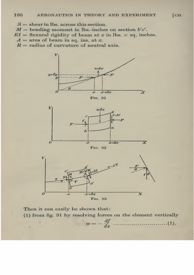
8/13/2019 Aeronautics in the 00 Cow Lu of t
http://slidepdf.com/reader/full/aeronautics-in-the-00-cow-lu-of-t 194/365
166 AERONAUTICS IN THEORY AND EXPERIMENT [CH
S = shear in lbs. across this section.
M = bending moment in lbs.-inches on section h'c'.
EI = flexural rigidity of beam at x in lbs. x sq. inches.
A = area of beam in sq. ins. at x.
It = radius of curvature of neutral axis.
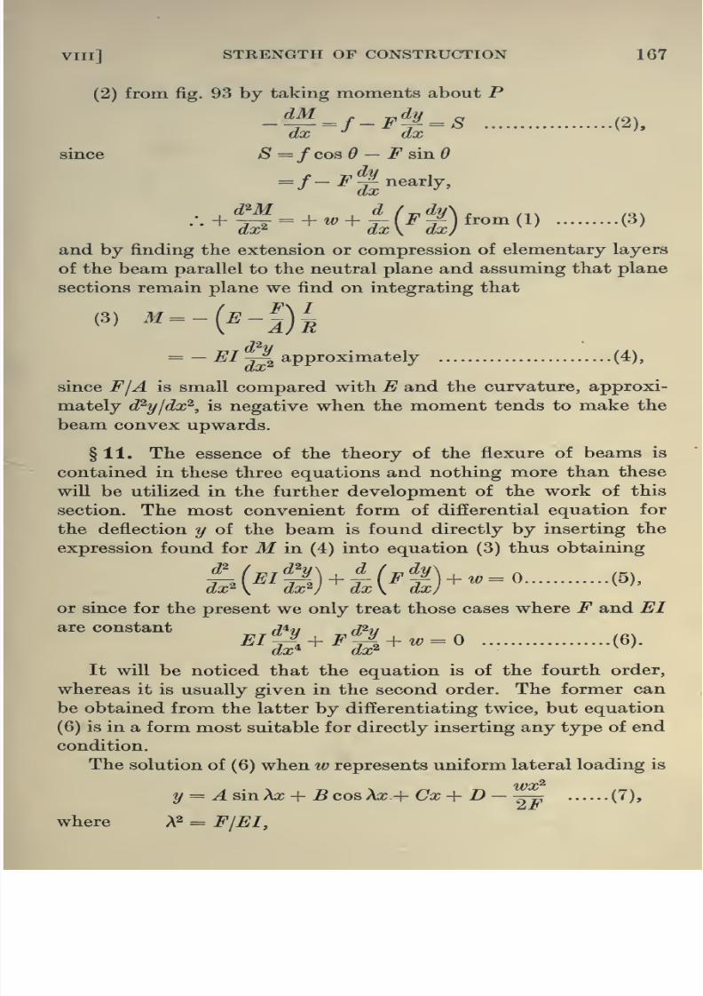
8/13/2019 Aeronautics in the 00 Cow Lu of t
http://slidepdf.com/reader/full/aeronautics-in-the-00-cow-lu-of-t 195/365
VIIl] STRENGTH OF CONSTRUCTION 167
(2) from fig. 93 by taking moments about P
_dM^ dj,^^(2).
since S =fco3d — F sinO
d'M d f^dy+'5--'^+i(4 )^-w (^)
and by finding the extension or compression of elementary layers
of the beam parallel to the neutral plane and assuming that plane
sections remain plane we find on integrating that
(^) ''-{^-iVrRd^V= — EI j\ approximately (4),
since FjA is small compared with E and the curvature, approxi-
mately d^y/dx^, is negative when the moment tends to make the
beam convex upwards.
§ 11. The essence of the theory of the flexure of beams is
contained in these three equations and nothing more than these
will be utilized in the further development of the work of this
section. The most convenient form of differential equation for
the deflection y of the beam is found directly by inserting the
expression found for M in (4) into equation (3) thus obtaining
U'^s^hli'ty-' <^»'
or since for the present we only treat those cases where F and EI
are constant /74.y ^2..
It will be noticed that the equation is of the fourth order,
whereas it is usually given in the second order. The former can
be obtained from the latter by differentiating twice, but equation
(6) is in a form most suitable for directly inserting any type of end

8/13/2019 Aeronautics in the 00 Cow Lu of t
http://slidepdf.com/reader/full/aeronautics-in-the-00-cow-lu-of-t 196/365
168 AERONAUTICS IN THEORY AND EXPERIMENT [CH
and A,B,C and D can be determined if the conditions at the end
are known. This solution can easily be verified by differentiating
and substituting in (6).
§ 12. Theorem of Three Moments. Suppose fig. 94 represents
a part of a loaded beam resting on a number of supports of which
three are indicated {A, B and C). It will be justifiable to discuss
the effect of the loading by concentrating attention on any portion
of it provided the effect of the remainder of the beam on that
portion is replaced by an equivalent shear and bending moment
at the ends of the portion considered. It is proposed accordingly
to find the effects of loading a series of separate beams AB, BC,
etc., assumed initially unconnected, and then to make these
continuous by the introduction of the requisite end conditions.
Y
El2,F2,JV2
Fig. 94
Let EI^ and j^Zg ^^ ^^^ flexural rigidities, F^ and F^ the end
thrusts,?iand l^ the lengths and w-^ and w^ the lateral loading
of the two bays AB and BC respectively. Let d^ , d^ and d^ be
the deflections and Mq, M^ and M^ the bending moments at A, Band C respectively.
Along BC.2
Uo sin Xc,x-{- Vo cos A, a: + WoX + Po —2F,
(8),
Vf\xQlQX^ = F^EI^.

8/13/2019 Aeronautics in the 00 Cow Lu of t
http://slidepdf.com/reader/full/aeronautics-in-the-00-cow-lu-of-t 197/365
VIIl] STRENGTH OF CONSTRUCTION 169
Ate
:.V,=
w I2
(^2 = U^ sin (/.2 + Fa cos 02 + Tf2 ?2 + -^2 - 2j^ ^
g = X,^ {U, sin <^2 + V, cos 02) +|-J
MJ,^ 1 ^<^2^2*
£'/2<f>2^
02* ^-^2
p _ , i^ ^2^,
^'^'^X^2 — % ~~
ETT » o +^/2 02' <^2*^^2
Tf,
..(9),
(10),
.(11),
1 Wol^^ 12
(12),
where 02 = Aa^g
Now the slope 6 at 5, where x = in the beam BC, is
dX /a;=o
_1
02 sin 02
'2^2
- M^ cos 02 -^ (1 - COS 02)| -^
+6^1 ii;2 I
20.-^^2 ^ ^^^^ ^^^^
_M^f 0^ }_ M2hf_±2 _A±_^i + ^Eh \ tan 6J ^^ ^/, Uin 0, / 00^ L ^ L02/
^2^2^ rtan02/2
[Eh I 02/2 J 07(13).
Similarly the slope at B where x = Z^ in the bay ^B is

8/13/2019 Aeronautics in the 00 Cow Lu of t
http://slidepdf.com/reader/full/aeronautics-in-the-00-cow-lu-of-t 198/365
170 AERONAUTICS IN THEORY AND EXPERIMENT [CH
Equating these two quantities we obtain
=-t+''>(r/3+| + ^x+A-. (15),
where 4=-L lf_± _i^_J_EI' ^^[sin^ y~Er'''
EI'cf>^A tan</.y~J5;/*^'
^^ w]^ rtan«^/2 1 1 _ wP7-
2EII (f>/2 J
(562 2EI
§ 13. The quantities a, ^ and y are given in the following
table for various values of<f)when F is positive, i.e. F represents
a compression, and by a', /3' and y when F is negative. Generally
we may write for the rth and (r + l)th bays
M,-i A, + M, (B, + Br+i) + M,+i4,+i
= -^^ +^,f^
+ A)_^+i^^+i^^^^ (16).
This provides an equation between the three bendijig moments
at three neighbouring simple supports in terms of the lateral
loading, length, flexural rigidity and end thrust of the two
contiguous bays, and the deflections at the supports. When thesequantities are known it is a simple matter to determine the
bending moments at all the supports of such a system if the
bending moments at two of the supports, usually the end supports,
be known; for by writing down the equation of three moments
for each set of three consecutive supports sufficient simple linear
equations are obtained to solve for the required quantities.
The bending moments at intermediate points along the bays
can then be found at once by differentiating equation (8) twice,
and multiplying by — EI, inserting the values for U, V, W and Pgiven in equations (9), (10) etc. and the values for the bending
moments at the supports as already evaluated.
The quantities on the right-hand side of equation (16) and the

8/13/2019 Aeronautics in the 00 Cow Lu of t
http://slidepdf.com/reader/full/aeronautics-in-the-00-cow-lu-of-t 199/365
VIIl] STRENGTH OF CONSTRUCTION 171
present form. This is most conveniently accomplished by neg-
lecting the end thrusts and deflections at the supports and
calculating the flexural rigidity and consequently the dimensions
of the spar from the bending moments that would be derived
under these conditions.
The various steps in the process will now be given for the
framework under consideration.
his Is, IS
r-l
i-H
CO
;-e- r>> ^-©- 21 -© -^
T H ^ '-^ -2 y-t O^ 1
^ §rH 1 -©.
IIII
lII
II
^s
00. ?-
•167
^^ II
•167 •333 •0833 •333 •0833'
•3 •167 •336 •086 •165 •331 •0826
•6 •175 •343 •088 •160 •325 •0805
•9 •186 •352 •091 •152 •317 •0774
1-2 •200 •367 •097 •]42 •305 •0730
1-5 •222 •395 •109 •131 •293 •0679
1-8 •261 •436 •125 •120 •278 •0634
21 •323 •501 •148 •108 •264 •0581
2-4 •444 •630 •197 •097 •250 •0531
2-7 •711 •935 •310 •0872 •237 •04813-0 . . •843 •0777 •224 •0441
3-3 — -•770 •0696 •213 •0401
3-6 -•684 -•484 -•262 •0620 •201 •0366
3-9 -•440 -•209 -153 •0553 •191 •0333
4-2 -•331 -•075 -•100 •0495 •181 •0305
4-5 -•278 •000 -•071 •0444 •173 •0278
4-8 -•252 + •066 -•060 •0390 •165 •0256
51 -•250 + 115 - -051 •0360 •157 •0235
Near 7r, a = —-
^ 1 2
W4 12 ,\
when 0=7r

8/13/2019 Aeronautics in the 00 Cow Lu of t
http://slidepdf.com/reader/full/aeronautics-in-the-00-cow-lu-of-t 200/365
172 AERONAUTICS IN THEORY AND EXPERIMENT [CH
Upper Spar.
Applying the equation to DCB we obtain since
Mj) = 648 lbs. ins.
648 X 48 + 2Mc (48 + 72) + ilf^ x 72 = 276000 + 1027000,
and for 05^
Mcx72 + 2Mb (72 + 72) + M^x12= 1027000 x 2,
and for B'AB, where B' is the point on the otherwing symmetrical
toB,
Mbx72 + 2M^ (72 + 72) + M^ x 72 = 1027000 x 2.
These equations give
Mj^ = 4620 lbs. ins.
71/^ = 5030 „ „
lfe=3790 „ „
j^j^M^xymOOlbsJni^ MzX2^4Z800lbs.ins? ^ M^Xj=4-Z800lbs.ins? .
Left Hand Half of B.M.Diagram fop Upper Zpar.
y>~^B'
HaF
B.M.Diagram for Lower Spar.
Fig. 95
Fig. 95 represents the bending moment diagram when the
end thrusts, etc. are neglected.
Lower Spar.
In this case the spar is pin-jointed at F and therefore M^ =

8/13/2019 Aeronautics in the 00 Cow Lu of t
http://slidepdf.com/reader/full/aeronautics-in-the-00-cow-lu-of-t 201/365
VIIl] STRENGTH OF CONSTRUCTION 173
The bending moment diagram for the lower spar is given in
Fig. 95.
§ 15. Calculation of Size of Spar, etc. The breaking stress for
spruce is roughly 8500 Ibs./sq. in. In the case given above the
loading is assumed four times normal and the factor of safety
will be taken as 2 throughout. Since the thrust will increase the
bending moments considerably, the factor of safety in the approxi-
mation will be taken as 3-6 ins.
The depth of the section is practically fixed by the thickness of
the wing section at the position where the spar is to be placed.
This thickness will be taken as 3-6 ins.
5030+ 5760 = 3400^,
•• 1-9 X (1-6)=
.*. A -= 2 sq. ins.,
giving a breadth of about If and / =5-1 (inches)*.
Taking E for wood as 1-5 x 10®, the flexural rigidity becomes
7-65 X 106 lbs. (ins.)2.
§ 16. Effect of End Thrust upon the Bending Moments. Wemust now use the general equation of three moments, which is,
when reduced to the form most suitable for our purpose,
M, .1 1, . 6«, + 2M, (/, . 3^, + /,+ . 3^,^i) + M,^i /,+ . 6a,+i
EIdr-i
+*a^:-.)-feh +''^-
,(17).
In the following table are given the quantities (/>, a, p and y
required for equation (17) in effecting the next approximation to
the bending moments.
Bay ^='Vm 6a 3^ 127
AB 1-97 1-76 1-41 1.64

8/13/2019 Aeronautics in the 00 Cow Lu of t
http://slidepdf.com/reader/full/aeronautics-in-the-00-cow-lu-of-t 202/365
174 AERONAUTICS IN THEORY AND EXPERIMENT [CH
The equations for the bending moments at the supports using
the tables for a, 5, y etc. now take the form
Upper Spar.
648 X 48 + 2Mc (48 x 1-00 + 72 x MO) + M^ x 72 x 1-20
-'»-»'i-°-s'---(f»-.a--fi+ 276000 X TOO 4- 1027000 x M8,
Mcx72x 1-20 + 2Ms (72 x I'lO + 72 x 1-41)
+ M^ X 72 X 1-76
+ 1027000 X M8+ 1027000 x 1-64,
and
Mbx72x 1-76 + 2M^ x 2 x 72 x 1-41 + M^ x 72 x 1-76
- 7-65 X 10«j-^^ X 2 + 1027000 x 1-64 x 2
giving Mj^ = 4800 lbs. ins.
i/^=5440 „ „
The deflection terms, it will be noticed, have very little in-
fluence upon the result and could be neglected for the upper spar.
Lower Spar.
2300 X 72 X 0-98 + 2M^ (72 x 0-99 + 72 x 0-91)
= 7-65 X 10«
I
-^^ + 0-272(J^ +^)]
+ 936000(0-98+ 0-88)
giving Mq = 5820 lbs.ins.
In this case the deflections play only a small part and might be
neglected in most cases.
Using these values for M^, Mj^, Mq, and Mq the bending
moment curves may be corrected as previously explained and the
spars re-designed. Comparatively little alteration as can be seen
has resulted from the inclusion of the end thrust etc., but this is

8/13/2019 Aeronautics in the 00 Cow Lu of t
http://slidepdf.com/reader/full/aeronautics-in-the-00-cow-lu-of-t 203/365
VIIl] STRENGTH OF CONSTRUCTION 175
and #2 previously used. Although this will probably have little
effect on the values of the bending moments as already obtained,
the stress due to direct thrust might be altered to a measurable
extent in some cases.
§ 17. Reaction at the Supports. Consider [fig. 96] an element
of the beam at a support. Let/j be the vertical shear to the left
of this element and/^ that to the right. Since this element is in
equilibrium the reaction R is clearly given by
«-/.-/.
^t
Fig. 96
Taking for example support B, fig. 94, then from (2)
when X is put equal to zero for the second bay BC.
Now
dy
dM d^y
•••^=^^^i|-^^^iwhen x=0. From (19) using (8) at a; =
(18).
(19),

8/13/2019 Aeronautics in the 00 Cow Lu of t
http://slidepdf.com/reader/full/aeronautics-in-the-00-cow-lu-of-t 204/365
176 AERONAUTICS IN THEORY AND EXPERIMENT [CH
giving
R2--\ {Mo -M,-F, {do - d,)} + ^
^ — M^-FAd^-d^)}^ ^'^'^{M, .(22).
But originally the reaction was taken as J {wj^-^ + wj,^) and
thus the effect of the continuity of the spar, etc. increases the
upload at the joints by an amount given by
J {w^ li + W2 12}— -^2 = R'/ ^^y
= - {if -M,-F, {do - d,)} - } {M, -M2-F2 {d, - d^)}.
-(273-^55) lbs -(2120+ 143)/bs. -{5760+246)lbs.
(Z78+55)lbs.
Fig. 97
The increased loads at ^, 5, C etc. (fig
become
XJfjper Spar,
1
(Z1Z0+143)lbs.
I will therefore
R^'48
{658 - 3950 - 278 x 0-017} = 69 lbs.
1
J2^' = _ 69 - ^ {3950 - 5400 - 2120 x 0-137} = - 44-8 lbs.
Ri 24-2 -=^ {5400 - 4800 - 5760 x 0-272} 10-7 lbs.
R^' = -2 {Rb' + Re + Rd) = - 6-75 lbs.
Lower Spar.
Rh =-h) (2300 - 5820 - 278 x 0-137} - - 49-4 lbs.
jl^' = _ 49-4 _ i^ {5820 - 2120 x 0-272} = - 23*4 lbs.
Rf = - {Rh + Rg) - - 72-8 lbs.

8/13/2019 Aeronautics in the 00 Cow Lu of t
http://slidepdf.com/reader/full/aeronautics-in-the-00-cow-lu-of-t 205/365
Vlll] STRENGTH OF CONSTRUCTION 177
The estimate of the forces in the members has been affected
by approximately 10 per cent., an amount well worth considering
in the final calculation of the size of the members. This increase,
however, modifying but slightly the end thrust F, used in the
equation of three moments, and the deflections, there will be no
necessity to recalculate the bending moments. The bending
moment diagram when corrected for end thrust determined by the
original force distribution together with the forces set out in
fig. 97 may be taken as sufficiently accurate for determining the
stresses in the members.
If the members be now finally modified in dimensions to suit
the requirements of these stresses, very little modification will
be involved in the foregoing calculation by these changes. •
§ 18. The principles utiUzed in this analysis must be clearly
borne in mind. The biplane framework is in the first instance
assumed composed of just sufficient members to make it rigid
on the assumption that all the junctions present are pin-jointed.
The distribution in force calculated on this basis is then used as a
starting point and first approximation for a new framework in
which the spars are no longer regarded as composed of pin-jointed
sections but of continuous members.
It is clear that the continuity of these parts operates towards
strength in what is otherwise a rigid framework. Such a factor
is usually referred to as a redundancy. The fuselage it will shortly
be seen is an example of a structure essentially involving redun-
dancies.
Apart from those already encountered in the wing structure
itself, an attempt to face the question of the effect of longitudinal
loading on the wing spar in the plane of the wing immediately
brings into consideration the modifying effect of incidence wires,
themselves of a redundant nature.
§ 19. Rigidity and Redundanxiy offrameworks. The difficulty
of determining the force distribution in a structure, such as a

8/13/2019 Aeronautics in the 00 Cow Lu of t
http://slidepdf.com/reader/full/aeronautics-in-the-00-cow-lu-of-t 206/365
178 AERONAUTICS IN THEORY AND EXPERIMENT [cH.
to forces and couples applied to a particular member or members
as a result of the aerodynamic loading. This combination of forces
andcouples
can be resolved along three axes, and if it be knownwhich ties and members of the structure are eventually effective
in bearing the stress, then, and only then, can the several com-
ponents of the loading be treated separately, and their effects
superposed. That this is so, is apparent from the simple con-
sideration of the cross-bracing of a rectangular frame in which
the calculated distribution of the forces in the members will be
widely different according to which of the diagonal members are
assumed operative. In the case of the fuselage an axial torsion
at the tail will eliminate certain bracing wires and give rise to a
definitely calculable force distribution in the resulting geometric
frame. A simple down-load on the tail, however, would reintro-
duce some of these members and eliminate others. The algebraic
sum of the two-force distributions thus calculated on what are
essentially two widely different frameworks would not be even
approximately the same as that originated when both torsion
and download, say, operate simultaneously.
When experimental work which would provide an insight
into the physical assumptions and simplifications that might be
introduced is not available, mathematical analysis may provide
useful information if certain difficulties could be overcome.Principal among these is that involved in the question of re-
dundancies which owe their existence, of course, primarily, for
supplying stiffness to the elastic structure. Mathematically the
difficulty of treatment, where such members occur, lies essentially
in the fact that they are not always operative, and that generally
it is not possible to predetermine the conditions under which a
particular member may go out of action. This will depend
entirely on the extensions that arise in the material of the struc-
ture, and is consequently intimately associated with the manner
in which the load is taken up.
§ 20. Since a structure may in general be regarded as simply
members (ties and struts) and joints (ball and

8/13/2019 Aeronautics in the 00 Cow Lu of t
http://slidepdf.com/reader/full/aeronautics-in-the-00-cow-lu-of-t 207/365
VIII] STRENGTH OF CONSTRUCTION 179
In the special case in which three pin-joints in a plane frame, for
example, are on the same member tlie latter may be regarded, as
far as the geometrical specification is concerned, as the limit
of a triangle where two sides coincide with the third. If the frame
is under-specified, so that one or more of the joints has a degree
of freedom, the structure is non-rigid, while if it is over-specified
so that one or more of the members could be removed and yet
the relative geometrical positions of the joints remain unaltered,
the structure is redundant. Generally speaking, structures cannot
be absolutely classified into these three categories, since it is
evidently possible to have a structure of which the joints in one
portion are over-specified and those in another under-specified,
so that the resulting framework is partly redundant and partly
non-rigid.
Consider the case in two dimensions in which there are p
joints with one of the members assumed as held rigid. It is
proposed to investigate what conditions must be satisfied in order
that the structure be uniquely determined and not over-specified.
Let a particular member be one of two axes x and y. There
are then 2 (^ — 2) co-ordinates to be found for the remaining^ — 2
joints. These must be specified by the lengths of the remaining
(m — 1) members of the framework, providing m — 1 conditions.
Hence the necessary relation that must be satisfied is
m ~ 1 = 2j9 — 4,
or . m=^ 2p — 3.
This is usually obtained on the quite illegitimate assumption that
the framework is composed of triangles.
It should be remarked that the satisfaction of this equation
is evidently not sufficient, although it is commonly considered
so, since, as has already been explained, the m — 1 lengths might
be such as to over-specify quite consistently a certain number of
the joints and to under-specify to the same extent the remainder.
In such an event the framework will be partly redundant and
partly non-rigid. It can only be definitely stated in general that if

8/13/2019 Aeronautics in the 00 Cow Lu of t
http://slidepdf.com/reader/full/aeronautics-in-the-00-cow-lu-of-t 208/365
180 AERONAUTICS IN THEORY AND EXPERIMENT [CH.
is perfectly sound that every rigid non-redundant framework
must satisfy this equation.
A simple illustration that serves to throw further light onthese points is provided by the frame shown in fig. 98 a, where
AD, BE and CF are parallel and AC and DF continuous at Band E, or the more general frame fig. 98 b. The equation
m = 2p - 3
is clearly satisfied in both cases, but it is equally evident that
the frames are not rigid, but the forces inthe members
when the
frame is loaded will become infinitely large unless the parallelism
of AD, BE and CF be destroyed. The reason for this is simple when
it is noted that as long as BE and CF are retained parallel and
the lengths of AC and DF such as to keep AD parallel to BE,
the specification of the length of AD is unnecessary, since it can
be derived from the lengths of the other members.
Fig. 98 a Fig. 98 6
This illustration is of particular interest in view of the fact
that similar frameworks may arise in three dimensions, as in the
case of a fuselage.
In three dimensions the corresponding equation with its
equivalent restrictions can similarly be shown to be
m = 3p — Q.
The interpretation of these equations from the point of view
of the determination of the forces in the members is worthy of
consideration. If p be the number of joints in three dimensions,
then resolving the forces at each joint along three co-ordinates,
3j9 equations will be obtained. From equilibrium among the
externally applied forces there are furnished three directional

8/13/2019 Aeronautics in the 00 Cow Lu of t
http://slidepdf.com/reader/full/aeronautics-in-the-00-cow-lu-of-t 209/365
VIIl] STRENGTH OF CONSTRUCTION 181
This indicates that the definition of a rigid, non-redundant frame
is essentially one in which the forces can be obtained by direct
resolution, but it is important to remark that, when certain
relations are satisfied, the system of linear equations determining
the force distribution under a special type of loading for an other-
wise rigid, non-redundant frame might contain two or more
equations which are identical, and the distribution would thus be
indeterminate. In a sense, therefore, the framework will be
redundant to aparticular type of loading
and would require to betreated as such.
On the other hand, if the structure shown in fig. 98 h be
subjected to loading (where AD and CF are parallel and BE just
not parallel to these), and if the structure be elastic so that under
loading AD, BE and CF may be deflected and become parallel,
the whole framework suddenly assumes the nature of a mechanism
and collapses. The framework is in fact unstable.
§ 21. In view of the fact that these equations are not in
themselves a sufficient criterion for determining when a structure
is rigid or otherwise, and in view of the necessity for this deter-
mination before stress calculations can be entered into, further
tests must be considered. Thus from an analysis of the frame-
work the redundant members must be fixed upon, supposed
removed and replaced by equivalent externally applied forces
acting upon the remainder of the frame now rigid and non-
redundant. The analysis would normally proceed according to
the principle of strain energy or a method to be given later in this
chapter, but in general it is extremely difficult to specify where
exactly the redundancy lies, and accordingly what is to be thenature of the rigid framework to which the structure is to be
reduced. A number of methods might be adopted to simplify
a complicated framework. For example, it is clear that initially
all joints in a plane frame at which only two members meet may
be supposed removed together with the two members in question,
and the resulting frame will not be affected as regards the question

8/13/2019 Aeronautics in the 00 Cow Lu of t
http://slidepdf.com/reader/full/aeronautics-in-the-00-cow-lu-of-t 210/365
182 AERONAUTICS IN THEORY AND EXPERIMENT [cH
replaced in the case of a plane frame by a single member with
joints at the ends. This may also be done at intermediate points
where the member itself is continuous or is attached to the
remainder of the structure. This is legitimate in view of the fact
that such a self-contained constituent portion is rigid in itself,
and therefore is in essence equivalent to one member. The fact
that the rest of the structure may be joined to this equivalent
member at points other than the two ends does not vitiate the
conclusions, since fixing the self-contained portion in space
involves also fixing the position of these joints.
In certain cases it will be possible to transfer all intermediate
joints to the ends, but care must be exercised to avoid the intro-
duction of an extra degree of freedom to the remainder of the
structure. This often arises when the transformation involves
the coalescence of two members. In a like manner if any portion
of the structure in three dimensions is rigid and not redundantin itself it may be replaced by a triangular plate to which are
attached the various members originally connecting this fixed
portion to the remainder of the structure. The resulting inter-
mediate joints may then be transferred to any of the apices of the
plate, provided in so doing no extra degree of freedom is given
to the latter, a condition which can easily be tested in any par-
ticular case. It may not always be possible, of course, to find such
a triangle or tetrahedron from which to start off, but in most cases
it is the simplest and most convenient method of reduction.
In this connection it is worthy of note that it is advisable
in fixing the rigid, non-redundant frame from which to commence
the analysis to ensure that the rigidity does not depend on the
fact already brought out in figs. 98 a and 98 6. If the frame be
rigid because certain members are just not parallel, an analysis
of the distribution in force will indicate that these become ex-
cessively large, and the results wiU consequently be very inexact.
§ 22. Even when the framework has been thus reduced and
determined to be a non-redundant structure, it is not always a

8/13/2019 Aeronautics in the 00 Cow Lu of t
http://slidepdf.com/reader/full/aeronautics-in-the-00-cow-lu-of-t 211/365
VIIl] STRENGTH OF CONSTRUCTION 183
-p^ a ^
T \ ^^[
\:^p\a
^'i ^^Y ' ^AP ^
P y^
and rigid, for which Bow's notation will fail to determine the
force distribution for external loading. In fact, the method is
only really applicable in those very special cases in which one
joint at least exists in the framework at which there are only
two members, and not always even then. Only a very limited
class of two-dimensional rigid and non-redundant frameworks
are, however, of this nature, for it can easily be shown that a
framework may have as many as three members at every joint
undercertain conditions to be explained shortly, and yet the
frame will not be over-specified. It would then be impossible
to apply Bow's notation directly,
although by an artifice the
frame can be so modified as to
make it amenable to that
method. Consider in illustration
(fig. 99) a modified form of fig.
98 6, in which for simplicity
ABGD is a square and the
angles are as specified. There
are six joints and nine mem-
bers, so that the equation is
satisfied. By the method of
reduction already indicated it can easily be shown that the
frame is rigid and non-redundant, but three members radiate
from each point, so that Bow's notation cannot be applied
directly. Let the external forces W act along a diagonal. Then,
considering the joint A and replacing the member AB by the
two externally applied forces P at A and B, we find by resolution
along 45, p_7T V3^ W
at the joint E by resolution horizontally and vertically
and at the point BP - T3/2 = 0.
Fig. 99

8/13/2019 Aeronautics in the 00 Cow Lu of t
http://slidepdf.com/reader/full/aeronautics-in-the-00-cow-lu-of-t 212/365
184 AERONAUTICS IN THEORY AND EXPERIMENT [oH
remaining members determiDed by a direct application of Bow's
notation. In the present case, however, on account of the symmetry
of the loading and of the frame this is unnecessary, but the
artifice is of quite general application; it is, in fact, only necessary
to treat one member as an external force at one end and work
round to the other by the shortest route.
§23. The generality of this artifice is not limited to two
dimensions. It is a simple matter to show that rigid, non-redundant
frames can be constructed in three dimensions, from every joint
of which four members radiate, with six joints in all. Under these
circumstances, one of the members may likewise be replaced by an
equivalent external force, and the analysis carried through by
resolution of forces. There is, of course, no extended form of
Bow's notation for such a case, so that the method simply reduces
here to direct resolution, but it is impossible, as is normally done,to proceed from joint to joint, determining the forces step by step.
§ 24. Interesting cases of rigid frameworks, at every joint of
which at least four members meet, frequently arise in the simplifi-
cation of aeroplane frameworks by the
method of reduction already explained.
A case in point is that shown in fig.
100, where the quadrilateral ABCD,
not necessarily plane, has each of its
four vertices joined to the points Pand P'. It would appear at first
sight that the structure would col-
lapse under compression in the direc-
tion BD or AC, but this is not so. By Fig- 100
inspection it is seen that the equation is satisfied and that four
members radiate from each point. Generally, in fact, any
polygon of n sides not necessarily co-planar, every joint of which
is connected directly to external points P and P', will form a
rigid frame with 3n sides and n + 2 points, thus satisfying the

8/13/2019 Aeronautics in the 00 Cow Lu of t
http://slidepdf.com/reader/full/aeronautics-in-the-00-cow-lu-of-t 213/365
VIIl] STRENGTH OF CONSTRUCTION 185
§ 25. It may be stated then generally as a conclusion from the
foregoing discussion that any rigid non-redundant structure in
three dimensions under external loading can be analysed as far
as force distribution is concerned by the direct process of resolu-
tion of forces at each joint. A system of linear equations will be
obtained which can, of course, be solved. The analysis from this
point of view, in fact, may be used as a criterion when other
methods fail for determining whether the structure is under- or
over-specified. Unfortunately, this method of solution does not
commend itself to the drawing office, as no general graphical
method appears to exist for three-dimensional problems, but in
many cases of considerable importance it is possible to regard
certain three-dimensional frameworks—aeroplane fuselages and
wing structures in particular—as composed of plane or nearly
plane rigid structures fastened together, and to treat these
separately, due allowance being made for the effect of the junctions
between the component plane portions and for the small curva-
tures in the latter. The method, it will be seen, will apply in all
cases in which the structure may be developed into a series of
separate plane frameworks, provided it is possible to determine
by some means which components of the external loading are
taken up by the constituent developed elements of the structure.
In the case of a fuselage, where this method of development can
easily be carried through, this is no difficult matter for any type
of external loading at the tail. The investigation will at the same
time give an indication of the degree of approximation obtained
by assuming the sides of the fuselage plane.
§26. Analysis of Stresses in a Fuselage. For the present
purpose it will be assumed that the fuselage supposed inelastic
is of the type shown in fig. 101, neglecting for the present modifica-
tions due to position of cockpit, etc., although the method will be
applicable generally. The framework consists essentially of four
sides

8/13/2019 Aeronautics in the 00 Cow Lu of t
http://slidepdf.com/reader/full/aeronautics-in-the-00-cow-lu-of-t 214/365
186 AERONAUTICS IN THEORY AND EXPERIMENT [CH VIII
Rear face; top edge «/, &i' ... m/bottom edge a',h' ... m'
Bottom face; front edge a,h,c ... mrear edge a',h\c' ... ... m'
Size of Members (inches).
acfi = 11-1 aa'=0 ai6i = 19-75
Sf\= 21-^ 66'= 11 6iCi = 22-5
g'5ri = 30 cc' = 15 Cirfi=22-5
Ml = 30 gg' = 2^ (^161=22-5Ml = 30 mm' = 23 ei/i=22-5
mmi=28-5 /i5ri=22-5
SrA = 18
;?iA;i = 17-5
ifcimi =21-75
In elevation the longerons are straight between aa^ and ff^ , and also between
gg^ and kk^.
In plan the longerons are straight between cc^ and gg^, and between grgrj
and mmj.
The fuselage tapers to the edge aa-^ (a and a', a^ and a-^ are
respectively identical). The points m, m^ , m', m^ will be considered
as attached to the framework of the engine, which itself will be
regarded as a rigid structure, so that the four points k, A^^, k' , A;/
will then be uniquely fixed and not over-specified. For the
moment everything to the right of the bulkhead is excluded at k,
the cross-bracing is of the type shown in fig. 101, provided only
one of the bracing wires (chain dotted) is operative, and k, k^ , mk,
etc., are rigid members with ball and socket joints at m, k, etc.
Hence ultimately the four points 6, 6^, 6', h^ will also be
uniquely fixed, but this would give rise to one redundancy at
the rudder post unless it be supposed that the latter is replaced
by a rectangular frame a, a^, a', a/, where aa' and a^a^ are
very small and jointed at these points to their respective longerons,
abc ... ajj^c^ ... a'h'c' ... and a^h-^c^. A diagonal wire or strut
inserted across this frame will make the conditions identical with
those arising from the existence of the rudder post, and this
redundancy must be specially treated by the ordinary strain
energy or an equivalent method to be considered later. The cross

8/13/2019 Aeronautics in the 00 Cow Lu of t
http://slidepdf.com/reader/full/aeronautics-in-the-00-cow-lu-of-t 215/365
.•>fi^ ^
%^
'Si
u
^ 'Si

8/13/2019 Aeronautics in the 00 Cow Lu of t
http://slidepdf.com/reader/full/aeronautics-in-the-00-cow-lu-of-t 216/365
188 AERONAUTICS IN THEORY AND EXPERIMENT [CH
conveniently reproduced by the application of external forces at
the joints. For the present, however, there will merely be con-
sidered forces due to the rudder and fin, tail plane and elevators.
Assuming no redundancies in the type of loading, this may be
conveniently represented as consisting of forces of 0-51f , say, at
a on ah and a' on a'h' acting directly downwards, due to tail plane
and elevators, and lateral forces of 0-6TF and 0'2W in opposite
directions along a^a^ and aa' respectively as in fig. 101, originated
by the lateral force on the rudder. For complete generality in
loading there ought strictly to be included other forces and
moments also—for example, moments about aa^ and about an
axis perpendicular to the plane of symmetry of the machine. These
are not taken into consideration, as their magnitudes, depending
partially upon the manner of connection between the tail system
and fuselage, are very variable.
The fuselage may be regarded as consisting of four developedand entirely separate sides with their respective cross-bracings,
struts and longitudinals.
In the actual fuselage considerable trouble must arise in
the neighbourhood of the rudder
post, on account of the nature of
the redundancy present. From an
analysis of this must be determined
the precise manner in which the
external loading at the tail will be
taken up by the constituent de-
veloped faces. Where the redun-
dancy actually exists can be seen a
consideration of the structure at
the tail. (Fig. 102.)
The four points 6, 6', 6^, 6/ are fixed by the remainder of the
structure between that bulkhead and the engine frame. The
tetrahedron a-^ab^h^ may be removed from the structure, being
self-contained and rigid, and there remains only the pyramid
ahbibi'b'. The last four points being fixed, a also will be fixed
Fig. 102

8/13/2019 Aeronautics in the 00 Cow Lu of t
http://slidepdf.com/reader/full/aeronautics-in-the-00-cow-lu-of-t 217/365
VIII] STRENGTH OF CONSTRUCTION 189
present, but the situation is otherwise when a lateral force or a
twisting couple is also present. In this case the component
w wloadings on the faces may be considered as ^ + P and ^ — P
where P is determined by the nature of the redundancy, and must
be specially treated as such. Even when the rudder post is
regarded as the limit of a very narrow rectangle with cross-
bracing the same consideration applies, the redundancy appearing
as a compression or a tension in the rudder post. If the faces
of the fuselage are plane and there are no cross-bracings in thebulkheads, then w is zero and the download is equally distributed.
For the present, however, only the non-redundant frame
will be considered, and it will then be accurately true to suppose
that the loading is taken up, so that the force 0-5Tf acts on ab
and is distributed in the vertical face containing this member
according to the method shortly to be outlined. Thus this vertical
face is supposed developed into a plane surface and treated as
a simple framework with the points m and m^ rigidly fixed. In
the same way the loads 0-5If on a'h\ 0'6W along a^a/, and 0-2W
along aa' may be considered as acting upon the respective faces
developed into the corresponding plane frameworks. In normal
practice this is, of course, the method usually adopted where the
forces in common members are added algebraically.
The modification of this method that will now be adopted
here will furnish the forces in the members in the fuselage under
the given conditions of non-elasticity and non-redundancy exactly,
but it will be seen that the results of the foregoing method provide
a fairly good approximation to the truth when the frame is
modified, as stated above.
§ 28. Consider the four faces developed into four distinct
plane pieces, the common longerons supposed split in such a
manner as to leave the stresses in corresponding members equal.
This is no assumption, of course, but only a convenient method
of regarding the question, since the cross-sections of the longerons
do not enter as a factor in the problem at all. It is proposed

8/13/2019 Aeronautics in the 00 Cow Lu of t
http://slidepdf.com/reader/full/aeronautics-in-the-00-cow-lu-of-t 218/365
190 AERONAUTICS IN THEORY AND EXPERIMENT [cH VIII
positions. The next step is then clearly to discover how these
constraining forces are taken up by the various members of the
structure. Let then the four developed faces be brought togetherto coincide as they would in the original structure along aa^,
a'a{, a-^a^, ah, a^b^, a'b', a(h{, but otherwise plane. The points
m, m^, etc., at the extreme ends must for the moment be assumed
fixed in space in their new positions. There is, of course, so
far no connection between the four faces except at the rudder
post at which the loads are applied. Under these circumstances,
the force distribution will be identical with that already derived
by Bow's notation. Clearly the two portions of the longerons
into which a-})-^ was divided may be bound together without the
introduction of any constraints, and the force distribution to
the right of the first bulkhead is now definite and cannot be
altered by any modifications to the left of that bulkhead. Thus
the tensive force in the wire ah^ , fig. 101, is given by CD, fig. 103 a,
the force in ah is given by the algebraic sum of the forces (in
this case the absolute differences) represented by AD, fig. 103 a,
and AT), fig. 103 d, and similarly for the other members to the
right of the bulkhead 66^
Now suppose the vertical sides bent round, about the positions
66i, h'h{ respectively, so that the constituent elements of each
of the longerons h^^, h^c^, he, h'c' coincide. To maintain this
position certain constraints must necessarily be introduced, and
it remains to estimate these. Consider the constraint at 6. To
maintain the force distribution in the front face a constraint equal
and opposite to R, fig. 101, obtained by finding the resultant
of the forces in the three members ha, he, hc^ in the bend position
must be applied. R is clearly a force in a horizontal plane and
provides a measure of the additional force that the whole frame
to the left of the bulkhead hh^ must take up. In the same way
the forces R^, R' , R^ which the frame must take up at the other
corners in order to maintain the fuselage structure to the right
of the bulkhead cc-^ can be derived. These forces must now be
treated as external loads for the remainder of the undeveloped

8/13/2019 Aeronautics in the 00 Cow Lu of t
http://slidepdf.com/reader/full/aeronautics-in-the-00-cow-lu-of-t 219/365

8/13/2019 Aeronautics in the 00 Cow Lu of t
http://slidepdf.com/reader/full/aeronautics-in-the-00-cow-lu-of-t 220/365
192 AERONAUTICS IN THEORY AND EXPERIMENT [cH
straints. From fig. 103 a and 103 d the force in he is given by the
algebraic sum of A^F, fig. 103 a, s^ndiA^E^, fig. 103 d. In the upper
face the wire h^c^ is in tension, while in the lower face it is the
wire ch'. In fig. 103 the difference between points such as F and F'
represents the effect on the force distribution of the constraints.
By the same process we may proceed step by step along the whole
fuselage. It is evident that should any one of the bracing wires
go out of action by appearing as a compressive element in the
calculation, and therefore its neighbour enter, it will merely be
necessary to repeat the calculation for that compartment, irre-
spective of previous steps, on the assumption that the neighbouring
wire in the stress calculation is capable of taking up compression.
This method can be carried through with rapidity and considerable
accuracy. Fig. 103 and the table on p. 193 indicate that the
effect of the constraints is comparatively small.
§29. Method of evalimting Forces in Redundant . Members.
The difficulty of selecting the redundancies in any framework
has already been discussed at some length, and before proceeding
with an analysis of their effects this must be overcome. A re-
dundancy, existing as it does in general to supply additional
strength to the structure, depends for its operation upon the elastic
properties of the material of the framework, in so far as these
determine the deflections. The method that is usually adopted in
treating problems of this nature is that known as the strain energy
method. In this method the redundantmembers are first fixed upon,
supposed removed from the structure leaving a rigid non-redundant
framework, and replaced by externally applied forces of unknown
magnitude, but equivalent to those exerted by the eliminated
members. The force distribution in the framework can now be
obtained by direct resolution in terms of the unknown applied
PHforces and the strain energy function built up, viz : ^ = S J
=-.
where P is the force in a member of which E, I, and A are the
elasticity, length and cross-sectional area respectively. The forces
are then obtained by differentiating this function with respect

8/13/2019 Aeronautics in the 00 Cow Lu of t
http://slidepdf.com/reader/full/aeronautics-in-the-00-cow-lu-of-t 221/365
VIIl] STRENGTH OF CONSTRUCTION
Forces in Terms of W.
193
Bay Member Plane Frame Constrained Frame
1 Strut aa^
Longeron ab -108 -1-08
fiibi + 113 + 113
„ a'b' -0-32 -0-32
ai'bi -113 -1-13
Wire ab. 0-79 0-79
ab,' 0-79 0-79
2 Strut bbi -0-395 -0-395
b\' -0-395 -0-395
bb' -0-07 + 0-06
bA' -0-2 -0-328
Longeron be -1-82 -1-80
b^Ci + 1-78 + 1-76
„ b'c' -0-89 -0-87
„ 6/c/ -101 -1-03
Wire be. 0-6 0-6
b'c,' 0-6 0-6
b,'c. 0-69 0-69
be' 0-23 0-23
3.
Strut cc. -0-318 -0-318c'c,' -0-318 -0-318
„ cc' -0-124 -0-07
CiC,' -0-372 -0-415
Longeron cd -2-31 -2-29
Cid, + 2-88 + 2-85
„ Cd' -0-95 -0-97
„ c,'d,' -1-09 -1-12
Wire cd. 0-43 0-43
Cd, 0-43 0-43
c,'d. 0-72 0-72cd' 0-24 0-24
4 Strut dd. -0-267 -0-267
d'd,' -0-267 -0-267
dd' -0-131 -0-131
d,d,' -0-392 -0-392
Longeron de -2-71 -2-69
„ d,e. + 3-81 + 3-78
d'C -1-04 -1-02
d,'e,' -1-21 -1-24
Wire de. 0-33 0-33
„ d'e,' 0-33 0-33
d,'e. 0-59 0-59
„ de' 0-197 0-197
5 Strut ee. -0-23 -0-23
Ce,' -0-23 -0-23
„ ee' -0-116 -0-116
e,e,' -0-35 -0-35
Longeron ef -3-03 -3-01
+ 4-52 + 4-49

8/13/2019 Aeronautics in the 00 Cow Lu of t
http://slidepdf.com/reader/full/aeronautics-in-the-00-cow-lu-of-t 222/365
194 AERONAUTICS IN THEORY AND EXPERIMENT [CH VIII
identical with the force in that member. This statement, however,
depends for its truth on the fact that Hooke'slaw applies. Actually
the equations derived by differentiation are simply statements
of the equality of the deflections of the redundant members
under the forces acting in them, and those of the rest of the frame
under the applied forces, including the equivalent forces from the
redundant members. On account of this, the actual derivation
of the strain energy is a useless step, since the deflection equations
can be written down directly without explicitly involving the
assumption of the truth of Hooke's law. Thus, suppose the
redundant members replaced by forces P, Q, etc., as before. Let
F be the force in any non-redundant member, and suppose the
latter replaced by it. Then from the geometry of the structure
where P, Q, etc., are the forces in the redundant members supposed
externally apphed, and W^, etc., are the real external loads. Since
the deflections are supposed so small that the geometry is un-
changed, this expression for F may be presumed unaltered after
deflection.
Let Sj,, 8g, etc., S„,, be the deflections of the points of
application of the forces P, Q, etc., TF^ due to an extension
between the points of application of F (i.e., of the member
containing F), the work done under these deflections must be equal
to zero. Hence
Fe = Ph^+Q\+ ... + Wh^,
:, Sj, = ae
hq = he
etc.
The total deflection of P due to the extensions of all the
members will be
Yioe = — total deflection of the member under its own force
EA'

8/13/2019 Aeronautics in the 00 Cow Lu of t
http://slidepdf.com/reader/full/aeronautics-in-the-00-cow-lu-of-t 223/365
CHAPTER IX
CRITICAL BEHAVIOUR OF STRUCTURES
§ 1. In the previous chapter an illustration has been given,
and cases may be multiplied, of a rigid structure of such geo-
metrical form, that whenever any finite loading whatsoever is
applied to it the forces brought into being in the members are so
large that the structure must collapse. An inherent assumption,
however, in this illustration is the fact that the elastic properties
of the material are presumed not to come into play. Under such
ideal conditions it may be stated that such a geometrical structure
acts in a critical manner under any loading.If,
however, themembers be composed of an elastic material such as wood or
metal, the critical geometry, while still operating to bring into
play excessively large forces and deflections, will not necessarily
involve the complete collapse of the structure on account of the
counterbalancing effects of the elastic properties, but will become
apparent by deflections excessively large in comparison with those
of a non-critical structure. It is generally assumed in an analysis
of the stresses in structures, as, for example, occurs in the beam
theory, that the deflections which occur are always small in com-
parison with the lengths of the parts. By this means, justified on
physical grounds, simplifications are introduced into the mathe-
matical analysis which render it capable of treatment. It becomes
at once evident therefore, that where critical conditions such as
those indicated arise, these assumptions are at once invalid, but
paradoxically enough, instead of rendering such cases incapable of
treatment, the analysis indicates at once where they arise in
virtue of the state of affairs resulting from the violation of the
fundamental assumption of small deflections. In fact the treat-
ment of critical cases resolves itself into the determination of the

8/13/2019 Aeronautics in the 00 Cow Lu of t
http://slidepdf.com/reader/full/aeronautics-in-the-00-cow-lu-of-t 224/365
196 AERONAUTICS IN THEORY AND EXPERIMENT [cH
of the material. Included in the geometry there must be the
nature, magnitude and direction of the external loading. Every-
thing in fact that may be represented by a line drawing of theproblem. Two illustrations probably familiar to the student may
here be brought to his notice. If a strut of uniform cross-section
and homogeneously elastic be simply supported at the ends and
placed under end thrust as in the case of the gap struts in the
previous chapter, the end thrust, presumed for the moment
eccentrically placed, may be increased up to a certain definite
amount without the deflections becoming other than small. At
this value the deviation from the straight becomes excessively
large. Under these circumstances the strut is usually referred to
as being critically loaded.
A second illustration will probably spring to the memory of
the engineering student. If an ordinary shaft supported at the
ends has its rotational speed increased from zero upwards, the
central axis of the shaft remains imdeflected or very approximately
so until a certain rotational speed is reached in the neighbourhood
of which the curvature of the shaft very rapidly increases and the
latter is said to whirl. If the speed be rapidly increased above
this point the deflections rapidly diminish and for a further range
of speed the shaft remains straight until once more a higher speed
is attained at which deflections again become excessively large
and whirling is reproduced. The various rotational speeds at
which this whirling occurs are referred to as critical speeds.
§ 3. The whole theory of flexure of beams as usually treated
is based on the assumption that the forces brought to play upon
them are such as to give rise to only small deflections, and small
curvatures. If anything, however, is striking about a critical,
it is that the deflections are certainly not small but extremely
large in comparison to the deflections obtained under normal
conditions, and therefore at a first glance it would appear to be
evident that the ordinary theory specially excluding this possi-
bility, could give us no information with reference to the state

8/13/2019 Aeronautics in the 00 Cow Lu of t
http://slidepdf.com/reader/full/aeronautics-in-the-00-cow-lu-of-t 225/365
IX] CRITICAL BEHAVIOUR OF STRUCTURES 197
investigation, but merely the particular value of the end thrust
at which a strut of any given variation in flexural rigidity, gives
this extremely large deflection from the normal.
The real crux of the matter will therefore be settled when the
criterion that must be applied to the ordinary theory of small
deflection is fixed.
Without entering into any elaborate proof of the matter,
however, it is clear that what distinguishes crippling from ordinary
cases of flexure is the inordinately large deflections and therefore
bending moments obtained. To all intents and purposes they are
too large to allow of a legitimate application of the ordinary theory.
The mathematical treatment based on this theory would express
such deflections and moments as of infinite magnitude, and
therefore if we wish to state the mathematical criterion for
crippling in an investigation, using the ordinary theory, we must
express it by saying that the deflections and bending momentsare of infinite magnitude. The conditions under which this occurs
will determine the conditions under which crippling occurs.
§ 4. As a simple illustration of the direct application of these
considerations to the crippling of a strut of variable flexural
^
Fig. 104
rigidity, let AB be the strut of length I, of flexural rigidity EI^
varying along the length according to any given law. The bending
moment on the section at P of coordinate (xy) due to the constant
end thrust F is Fy. The restoring moment at any point P is
Flexural Rigidity x Curvature

8/13/2019 Aeronautics in the 00 Cow Lu of t
http://slidepdf.com/reader/full/aeronautics-in-the-00-cow-lu-of-t 226/365
198 AERONAUTICS IN THEORY AND EXPERIMENT [CH
EI Fy,
0.
To determine the criticals we require to solve this equation
subject to the end conditions, say tliat at x ^^ and x = I the
deflections have definitely assigned values while at intermediate
positions they become infinitely great. Before showing how this
may be performed with perfect generality consider the following
particular case.
Take the strut which is one of the series given by (fig. 105) a
symmetrical section of length I
of the ellipse. The principal
reason for selecting this illustra-
tion, apart from its practical
utility, is that it will serve as
a check on the theory as later
developed. By variations in the magnitude of the quantities a
and b an infinite series of struts can be obtained, including very
close approximations to those of most frequent occurrence in
aeroplane practice.
The ordinates are then given by
b V aV '
Since the moments of inertia are proportional to the fourth power
of the ordinates, this gives
Fig. 105
where Zq = moment of inertia at central section.
The equation whose solution is required subject to the criterion
of crippling is
d^^y
+Fy
0.

8/13/2019 Aeronautics in the 00 Cow Lu of t
http://slidepdf.com/reader/full/aeronautics-in-the-00-cow-lu-of-t 227/365
IX] CRITICAL BEHAVIOUR OF STRUCTURES 199
The deflection curve will thus be completely specified provided A
and B be determined from the end conditions. It becomes at once
apparent that unless a slight deflection be given to one or other
of the ends ideally no flexure whatever will take place, for A and B
will both be zero. Let us assume then that at
x==- 1/2, 2/=
and at a; = + 1/2, y = a.
Crippling will then occur when the deflection at any point becomes
infinitely great in comparison with a.
Inserting the end conditions this gives
providing two equations to solve for A and B.
Performing the algebraical solution it is easily seen that the
expressions for both A and B will have as denominator
,a+?/2/ [a -1/2) '
If the deflections are to become infinite, A and B must become
infinite, and therefore the condition for crippling takes the form
c
[a +112) [a -1/2)
(2a+l\^^-,
[2a--^l)=^'-
It must be remembered that A contains the imaginary quantity i.
so that there are other solutions of this equation in A besides A = 0.
In fact /2a+A
and remembering that g 2nrri ^ 2
where n is any integer, it follows that

8/13/2019 Aeronautics in the 00 Cow Lu of t
http://slidepdf.com/reader/full/aeronautics-in-the-00-cow-lu-of-t 228/365
200 AERONAUTICS IN THEORY AND EXPERIMENT [CH
giving Eh1 +
12a+h2
2a -Ij
as the expression for the various crippling loads.
For convenience in calculation it is frequently better to write
1-4a2
moment of inertia at endmoment of inertia at centre
'
so that
F=iEIA^-^]\l +,2^2
loj1 + VI - r
1-ViThe limit of this expression for r = 1 is easily shown to give
which is Euler's value.
The case ioin = must be excluded for this would give
Fa^ = EIq,
and the solution obtained is illegitimate. The first crippling load
is thus
F-fil-r) 1 +
o-i^vi^:)
When r is made to differ slightly from unity so that the strut is
nearly straight this gives
i^ = p(8-58 /o+l -29/1).
When r = 1/2 so that the moment of inertia at the end is only 1/4
that at the mid-section

8/13/2019 Aeronautics in the 00 Cow Lu of t
http://slidepdf.com/reader/full/aeronautics-in-the-00-cow-lu-of-t 229/365
IX] CRITICAL BEHAVIOUR OF STRUCTURES 201
But for a uniform strut
^=^/v-9-86^«.
c^Hc-
«D § s g o ^^ 5? S S S— ^ o o o <t> o o
^1^^ 2 «S 2 § g i§ i i 1
V CO
§ 1 sfe
«sc^ %
1 Oi '^ CvJin 9 §§ O
CS)
o o o
^^§\ \ ^ \\\ \ \ \ \
\
\ \ \ /
'/7 ^
-^
^\ \
/ / // /
1K\
\////
/
tt \ \ \ / / // /
\ \ \ / / // /T> \ \ \ / /
s \ \
'
/ 7•5
1
- \ \ // / /?>'
\\
\(// /
3 \ \\ /// / iO
C g \ \/// / tO o
-t?
1
\\
\ //o
to
1 \1p \
1fin
o§^^
's- - V /O H 7 a.
'
c 1ifi>^°
,. »\,^<^ T.i \S
,i^-N ^ -Tl
<S.I ^1 t. i|\ll
=1 ^1 i)\ \
3
bo
J
1
I \\III
^ tj: cs^^^
^^(^£^^-1
1 1 1 I
Goc^«oift'*coej-HOoaot^oinT)<coc>jr-< D'1 -1 ^ 1 ^ -. -H ^ -H C:> cb c5 Cb cb cb cz> c3 <b

8/13/2019 Aeronautics in the 00 Cow Lu of t
http://slidepdf.com/reader/full/aeronautics-in-the-00-cow-lu-of-t 230/365
202 AERONAUTICS IN THEORY AND EXPERIMENT [CH
various values of r, and a comparison made in each case for the
weights and aerodynamic resistances between the strut in question
and a uniform one of equal strength and length. All cross-sections
are calculated by taking them proportional to the projected area
of the strut normal to the stream. It appears at once that in the
neighbourhood of r^ = 0-05 both the relative weights and resist-
ances are simultaneously a minimum. This therefore corresponds
to the best strut of minimum weight if its sections are so selected
as regards drag as to be most nearly streamline,
§ 5. Returning to the general problem of the crippling of a
strut of any given law of variation in flexural rigidity, the equation
to be solved is ^2^ ^
where I is some given function of x.
In the drawing office the law of moment of inertia will not
generally be specified by means of an analytic expression but
rather in the more convenient form of a curve. The method of
solution therefore most suitable for such conditions will evidently
be one depending on graphical methods of integration.
Without entering into any proof of the matter the solution of
the given equation
maybe written
y^A[x - ^ [;.4;|-^ ^^/;.. [If f> [;|-
+ ^f-^V'^JoW + no''^Jol7l„<^^j„W--t'
where A and B are arbitrary constants and the terms in the two
infinite series are each two integrations higher than the preceding
one according to a simple law.
We may write this
y = AU {x) + BV {x).
A and B are to be obtained from the end conditions, viz.
x=0, y = yQ,

8/13/2019 Aeronautics in the 00 Cow Lu of t
http://slidepdf.com/reader/full/aeronautics-in-the-00-cow-lu-of-t 231/365
IX] CRITICAL BEHAVIOUR OF STRUCTURES 203
When these equations are solved for A and B, it is seen that they
have the common denominator
U{0)V{1)-V(0)U{1).
As already explained, crippling will occur when the deflections
become infinite in comparison with y^ and y^, and this demands
that the above expression vanishes.
Hence u (q) V {I) - V (0) U (l) = 0.
But from the expressions for U and V it is clear
U (0) = 1,
V (0) = 0.
Hence the condition for crippling becomes
a'^Jo^-^^ JoHWoH^-^'^^'-.e. I
This is an equation containing an infinite number of terms as an
equation to solve for F the crippling force.
But the formula is not nearly so formidable as at first sight
appears.
In the first place, each of the terms in this expression can
be obtained with great rapidity by a simple process involving
nothing more than the use of an ordinary planimeter, or the
integration of a curve by the mean ordinate method. In the
second place itcanbe proved that the series is so rapidly convergent
that no more than the first few terms, no more in fact than the
terms actually given above, need be treated and the equation may
be considered as a quadratic in F, the lowest root being taken.
A first check on the validity of this series may be made by evalua-
ting the expression for the case of a uniform strut, where EI is
constant. The series then becomes
ffrl rx pi rl rx rx rx
l~ -pj \dx\ xdx + H^ dxj dx I dx \ xdx — etc. =

8/13/2019 Aeronautics in the 00 Cow Lu of t
http://slidepdf.com/reader/full/aeronautics-in-the-00-cow-lu-of-t 232/365
204 AERONAUTICS IN THEORY AND EXPERIMENT [CH
after multiplying by V{FJEI), where(f>= IVF/EI
sin </ = 0,
i.e.cf)= 7T,(f) = not being a solution.
For convenience in carrying through the graphical integration
it is advisable to throw the series obtained into a non-dimensional
form. This may be done by transforming it by the substitution
X = xjl,
and writing ^2 _ pi^jEI,
where I = IqR, 1q being the moment of inertia at the end, whence
we obtain
R '-'•
The graphical process is then extremely simple. The curve for
X/R is plotted for the range Z = to Z = 1, the whole length of
the strut, and the value of the integral obtained graphically by
means of a planimeter or by mean ordinates is plotted. This
y 7 -XT
determines —^ which is once more integrated for the range
Oto 1, and plotted. The value of the ordinate at Z = 1 deter-
mines the first coefficient, viz. dX -^-.
Jo Jo ^Each ordinate of the last curve is then multipUed by l/R
and integrated twice as before, and the value of the final ordinate
atZ = 1 determines the coefficient of </>*. In general it will not be
found necessary to proceed to higher terms but if necessary this
may be done with equal rapidity by multiplying by l/R and
integrating twice. After a little practice it will be found that this
whole process apparently complicated can be performed in half
an hour. The final operation obtained is then in the form
I - acj>'^ + h<t>^- ... = 0,
which, when solved for (j>^ and selecting the lowest positive root,
gives the value of FP/EIq which corresponds to the crippling load.

8/13/2019 Aeronautics in the 00 Cow Lu of t
http://slidepdf.com/reader/full/aeronautics-in-the-00-cow-lu-of-t 233/365
IX] CRITICAL BEHAVIOUR OF STRUCTURES 205
The symmetry may be introduced quite early by using as the
end conditions to determine the constants A and 5 in the expres-
sion for
ythe solution of the differential equation, that
at x = 0, y = 0,
atx=ll2, ^ = 0.
If this be done the condition for crippling then takes the form
U (0) r {1/2) - V (0) U' {112) = 0,
The integration now extends over half the length of the strut and
each coefficient is one integration less than in the asymmetric
case.
As before if we throw the series into the non-dimensional
form by writing x = 2x11,
it reduces to
-f/;^ 4;f;¥/: / -K
-6iJoflio'*^ioiri„'^^J„-ir +••• = ''
As an illustration of the application of this method, consider
the strut given by r == 1/4 in the system of elliptical struts already
treated {i.e. IJIq = 1/16 in our previous set).
For the strut the following table may be drawn up showing
the various stages in the calculations.
A little explanation may be necessary for this table. The first
three columns are of course derived from the dimensions of the
given strut, while column IV is obtained by direct integration of
the graph of column III. The coefficient of ^^' in the series is thus
1/4 X -757. For graphical convenience column V is introduced
where the maximum ordinate in IV is replaced by unity, all the
other members being divided by '757. This means that in the later

8/13/2019 Aeronautics in the 00 Cow Lu of t
http://slidepdf.com/reader/full/aeronautics-in-the-00-cow-lu-of-t 234/365
206 AERONAUTICS IN THEORY AND EXPERIMENT [CH
another factor. The coefficients of the terms that thus enter into
the series are always found at the head of the columns to the left
of the double vertical line.
XPSOl><»O»COOt>00e<5
X
(paonpai) a-
1—
><1
xpaI
(paonpoj) (7
XPD
(paonpoi)
=?
XPVh(poonpgj) Y
XPXj
kIx
uli
or--oOf-iu:)coco«(M^ (N «5 ^ I> Tt* (M ^ o o ><d
CO (N ^ ^ O O O O O O O ^
O t^ lO * CO (N I—I O O O O I—
COCOlOiX>aOQOQO<N»Crt(050cot^(Maoiocoi-HOCOCO<Nr-H,-HOOOOOO
I—I (N CO CO O lO 00rHCOTjiTt^lOt^OCOlO
OQOOIOtJ<CO(M<Mi—lOO
000(NCOIOCOCOOt1<l0<X)00i-<K5O«0C0.—lO•Tt<C0<N<MrH^OOOOO
lO QO »0 lO l> I> COt^COlO-^-^TtHT^TjHlO
OQOI>COlO-*CO<M^OO
lOCOt^OS^^COCOOOr-•«*l:-COiOTt<Tj<C0<M^i—lOO
^OlOUtlOOr-tO ^ )_|
O 05 QO 00 t^ t- t- t> t-CO
O HH
(M JO op lO t- lO CO
rH rl| rl|<N CO CO r^
00500t-CD»C-*CO(Ni

8/13/2019 Aeronautics in the 00 Cow Lu of t
http://slidepdf.com/reader/full/aeronautics-in-the-00-cow-lu-of-t 235/365
IX] CRITICAL BEHAVIOUR OF STRUCTURES 207
Equation to be solved is consequently
1 - 'lS9cf>^ + -00837<l>*- •00019</»« + .•• = 0.
Neglecting the term in ^^ and solving as a quadratic this gives
<^2 ^ g.Q approx.
To determine a closer approximation to the root let
<^2 _ 8-6 + A.
Inserting this in the equation and neglecting higher powers of A
than the first we find
1 - -189 (8-6 + A) + -00837 (8-62 + 17-2A)
- -00019 (8-63 + 3 X 8-62) + . . . = 0,
i.e. A = - 1-40.
Hence (/»2 == 7-2
giving as the crippling load
For comparison and as a check on the result we can evaluate(f>^
from the previous analysis of the elliptical set of struts when we
fiiid ^2 _ 7.25.
§ 6. Practical considerations in the Design of a Strut. The
foregoing analysis has presumed that failure can only ultimately
take place due to buckling or instability of a particular nature
and has ignored the possibility of other factors entering in which
would tend to cause collapse other than of this nature. For
example, if the yield point of the material were reached under an
end thrust far below the value already calculated it is evident that
Euler's value in case of a uniform strut might give no indication
of where this rupture would be expected.. The fundamental
assumption in fact has been made that E remains a definite
elastic constant right up to the crippling load, an assumption
clearly invaUd if the yield stress should be reached before that
point.

8/13/2019 Aeronautics in the 00 Cow Lu of t
http://slidepdf.com/reader/full/aeronautics-in-the-00-cow-lu-of-t 236/365
208 AERONAUTICS IN THEORY AND EXPERIMENT [CH
of uniform struts of various cross-sections much experimentalwork
has been carried through with a view to determining what devia-
tions, if any, occur from Euler's value. Gordon, as a result of aseries of tests on circular struts, deduced the following empirical
formula,f a
where
/c is the crushing stress of the material,
I is the length,
d the diameter,
and A the area of cross-section of the strut.
a = a constant = fJir^E, approximately.
This indicates that for short struts crushing is the main factor
in collapse, while for longer struts Euler's value approximately
holds good. An extension by Rankin to struts of any cross-section
gives the formula f ^
'&'
where K is the radius of gyration and
a=fj7r^E.
This is an attempt to take into account stresses due to direct
thrust and those due to bending, but unfortunately such a formula
applied to struts of any cross-section, as Rankin attempts to do,
must necessarily be inadequate for the stresses due to bending
will evidently depend upon the depth of section, a factor finding
no place in his formula. Much experimental work has since then
been carried through to investigate the deviations and causes of
deviation from Euler for a uniform strut. It has become in-
creasingly clear that such differences as do occur are in almost all
circumstances completely explicable in terms of such unavoidable
factors as lack of homogeneity of material, unavoidable ' eccen-

8/13/2019 Aeronautics in the 00 Cow Lu of t
http://slidepdf.com/reader/full/aeronautics-in-the-00-cow-lu-of-t 237/365
IX] CRITICAL BEHAVIOUR OF STRUCTURES 209
As an illustration of the nature of the results that have been
obtained, the following table, based on experiments on aeroplane
struts of half scale, may be taken as typical.
1 f->
JiX P
1 CO 2 l^ i> 10 t>05 Oi 05 05 05
rt 'Sp Qo 1-^
<
Equiva-lent
load
byEuler
000000000000OOOOC^JCfiiOOLOl-fMSD-*CO-<*l>iOOGOOOOQp«pl>CSIC^(N(NThMThlOlbrh->*Th
4i ®-Tj J3 o CO r-l CO
05 t^ 00 op
^ 6rH
6 6 6
-»j .—
.
Si.^15 «^ o g^ COtHCOCCKMOiMGO-^OOGO'*rt H ;^ i-HOt^OSCOOOMOOGOOOf^ '^ ^ r--(CpQ0I>l>COO5'7lCOI:^lOCO3 §^ s (N(>i<NCNicbcocb-^ThTh'*'>*^'^«2
-J3
K ^ <a
_S^o?, s-5^ n;2 OOlOt^COfMr^t^OSrHOSCO-*
mt COiOOiOiOfNOOC^fOp-Tto»OGibi>db6iMcb-^rHroo:i
3 •--; S 3^K © a (-
TJ T5
^^^p— ^ *^^^• Sh
13 3^ d
1S '^ISls
1^
1 lllat 1 1c2 >: >: ^ H^j S

8/13/2019 Aeronautics in the 00 Cow Lu of t
http://slidepdf.com/reader/full/aeronautics-in-the-00-cow-lu-of-t 238/365
210 AERONAUTICS IN THEORY AND EXPERIMENT [cH
of the quantity for a non-uniform strut depends upon the shape
of that member. In a later investigation it will be found that the
conception of the existence of such a non-dimensional constant is
not limited to this simple case but is of general significance in the
whole theory of structures and of particular import in the theory
of aeroplane structures.
§ 8. Consider the case of a structure of the type of an aero-
plane framework for example, where it is supposed that the
assumptions made in the ordinary beam theory apply to everypart. Let the length of one part, say a bay, be given by I, the area
of a particular section by A, moment of inertia I, and the elasticity
and density of the material of which it is composed E and p
respectively. Given these quantities for this one portion, it will
be assumed that the shape and geometry of the structure involve
an exact specification of how to derive the corresponding quan-
tities for the remaining portions. Let the external load be F,
applied in some given manner specified by the geometry, and
suppose this is sufficient to produce a stress just greater than the
yield stress/in the material of the weakest member. F can only
depend apart from the geometry and manner of appHcation upon
the quantities enumerated above, defining the properties of the
material. These are as follows
Physical quantity Symbol Dimensions
Young's Modulus
Area
Moment of Inertia
Length
Density
Yielding stressGravity
Load
EAI
I
P
f
1
LMjL^
MjLT^
Since F, the load which will cause collapse by rupture of the
material, must involve all these quantities grouped together in
such a manner as to make the dimensions of the product identical
with those of F, we may write

8/13/2019 Aeronautics in the 00 Cow Lu of t
http://slidepdf.com/reader/full/aeronautics-in-the-00-cow-lu-of-t 239/365
IX] CRITICAL BEHAVIOUR OF STRUCTURES 21
Equating powers of M, L and T,
X -\- q + r= 1,
— x+ 2y + 4:Z + p — 'Sq — r + s = 1,
X -{- r + s = I,
fy [Ay (glpy (l—aifrt)-©-©'
It will be more convenient to write this in the form
-¥(r(^.) © ©-.where instead of gl^p its equivalent W, the weight of the portion
of the structure considered, is taken.
It is evident that every term in the expression for F must take
the form given above, but so far no restriction has been imposed
on the values of the quantities r, s, y and z. Under these con-
ditions F could be represented as the sum of a series of terms in
which//^, Ajl^, W/fA, IjV^ could appear to anypower whatsoever
but in each such term EIjl^ would be a factor. This is equivalent
to the statement that
j,^EI (f A W I\
i^^KE'i^'fA'iy'
where i/j for the moment is an arbitrary function. Writing
cl>^= Fl^lEI (1)
so that this quantity may be considered as a non-dimensional
critical loading coefficient, it follows finally that
'f A w^ r'
fA' /*y
If it be desired to introduce in addition the depth d of the
section, then this will merely give rise to the extra term d/l in the
function.
It is clear from the definition of cf), that for a given structure
where I, E and I are known(f>
is uniquely determined when F, the
breaking load, is found, so that the discussion of collapse by rupture
'^'-Ki'i'^'i^
(')•

8/13/2019 Aeronautics in the 00 Cow Lu of t
http://slidepdf.com/reader/full/aeronautics-in-the-00-cow-lu-of-t 240/365
212 AERONAUTICS IN THEORY AND EXPERIMENT [cH
§ 9. Similarity of Structures. Out of the general class of frame-
work embraced in this discussion so far, let there be selected a
series of which all members are identical with respect to external
shape, differing only in magnitude. This implies that A the area
of cross-section of any selected part is proportional to l^ and 7 to l'^.
For this series, therefore, A/P' and I/l^ are constants depending
only on the geometry, and accordingly expression (2) now takes
the simplified form / f w \
'^'-'^4'7a) <''•
It is not difficult to give an interpretation to the two non-dimen-
sional quantities f/E and W/fA. The former being the ratio of
the yielding stress to Young's modulus may be taken as the strain
at the yield point, on the assumption that Hooke's Law applies
rigorously over the whole range. In the same way W/fA is the
ratio of the weight of a particular member, say the weakest, to
the maximum tensile or compressive force, as the case may be,
which that member is capable of withstanding without yielding
assuming that the section A is taken at the position of
collapse.
As far as a discussion of the breaking load coefficient ^^ is
concerned, it is evident that if a series of geometrically similar
structures be selected, two distinct variables, and two only,functions of the material ai ect the question. These are the strain
at the yield point for the weakest member, and the ratio of the
weight of that member to themaximum tensile or compressive force
it can withstand at the point of yield. It is equally clear, however,
that the so-called geometrical restrictions determining the dis-
tribution of the constants of the materials in a composite structure
are not absolutely vital to the above discussion, so that violations
of the laws determining the selection of the material from member
to member would not necessarily vitiate the conclusions arrived
at here. For example, one would not be rigorously entitled to
vary I, A and E in certain members, since such a change would
clearly upset the geometrical similarity of shape and the dis-
tribution of force with the possible result that the previously

8/13/2019 Aeronautics in the 00 Cow Lu of t
http://slidepdf.com/reader/full/aeronautics-in-the-00-cow-lu-of-t 241/365
IX] CRITICAL BEHAVIOUR OF STRUCTURES 213
remains so in the series. This is equivalent to an increased latitude
in the scope of selection of materials. '
Generally in experimenting with a model of this nature it is
convenient, of course, to have corresponding parts in the model
and the full-scale structure composed of identical materials. If,
for example, the frame of an aeroplane were under discussion,
wires in the model would be composed of the same metal as those
in the original, corresponding struts, spars, ribs, etc., of the
same wood.
Since the quantities/, E, I, p, etc., in the expressions for (j^^
all refer ultimately to the same part of the model, to ensure
geometrical similarity in the widest sense it follows that the
assumption thatf/E is a constant is one which is obvious experi-
mentally. Under these circumstances also W/fA, as can easily be
verified, becomes proportional to the linfear dimension I. The
breaking load coefficient 6^, therefore, when the weight of the
structure contributes towards rupture, is purely a function of Z,
and the form of the function is determined only by the shape of
the various parts, the geometry of the loading and the so-called
geometry of the material.
This expression for^'^
may likewise be supposed solved for I
in terms of <^. For every external load coefficient this equation
then determines the size of the structure corresponding to failure.
When there is no external load and failure is due to weight alone
</> = and the result previously anticipated is seen to hold.
§ 10. Structures of Negligible Weight. When the material is
not sufficiently heavy to involve the weight of the structureappreciably as a factor in causing collapse, the term WjfA may
be omitted in equation (3) and the expression for ^^ takes the
relatively simple form
7^^^ = ^.(1).
Let us imagine that the weakest member is replaced by another

8/13/2019 Aeronautics in the 00 Cow Lu of t
http://slidepdf.com/reader/full/aeronautics-in-the-00-cow-lu-of-t 242/365
214 AERONAUTICS IN THEORY AND EXPERIMENT [CH
plotted against //j^ will give a characteristic curve for the
structure of the given geometry. For geometrically similar
structures of which the corresponding parts are made of the samematerial, so that fjE is constant, the critical load coefficient
becomes an absolute constant for the series depending for its
value purely on the shape. It follows that a simple test to de-
struction on a model will suffice under these conditions to determine
the breaking load coefficient </>2, and therefore the breaking load Ffor any other member of the series.
§ 11. Failure Due to Instability. It is assumed in this section
that the failure is not necessarily accompanied by collapse or
rupture in the material but is due merely to permanent deforma-
tion of the configuration of the structure. It follows that in the
expression for the critical load, the yield stress does not enter
although all the other terms A, I, E, I, p, g may do so. Using ^^
as a critical load coefficient defined by Fl^/EI = <^2 ^j^g^
^'=^'(^'SItJ (*)'
obtained by the same method as in the previous section.
On the understanding that the structures in the series are all
geometrically similar as regards external shape without reference
to material composing them, then Ajl^ and I/l'^ are constants for
the series and / W\
'^'-Hea) (5),
where WjEA is the ratio of the weight of a member to the tensile
or compressive force required to produce unit strain at some
particular section of that member.
If corresponding members of the series are made of the samematerial then WjEA is easily seen to be proportional to I, from
structure to structure, and as before the critical loading coefficient
<t>^-^z(l) (6)
depends on the size only.
When the weight of the structure is negligible as far as its

8/13/2019 Aeronautics in the 00 Cow Lu of t
http://slidepdf.com/reader/full/aeronautics-in-the-00-cow-lu-of-t 243/365
IX] CRITICAL BEHAVIOUR OF STRUCTURES 215
It has been found that the critical loading for a uniform
prismatic strut of negligible weight under end thrusts and pin-
EIjointed at the ends is given by i^ = tt^ -™- , where I = length of
strut, I the least moment of inertia, and E = Young's modulus,
so that </> for this structure is tt. For a strut under the same
conditions but with fixed ends </> = 277-.
In certain cases of simple shapes of structures, it is obvious
that the function (j>^ may be derived by calculation as for example
in the case of the prismatic beam supported either on simple or
clamped supports, but for more complicated problems where the
calculation is too abstruse a number of points on the characteristic
curve may be derived by a series of tests to destruction on
models.
§ 12. In one other type of structure at least other than that
of a simple strut the crippling coefficient </> can be evaluated. The
case referred to, of extreme importance in aeronautical stress
calculations, is that which corresponds to the spars of a wing or
the longerons of a fuselage. For purposes of calculation these
members maybe supposed, with sufficient accuracy for the present,
to consist of a strut held by simple supports at a number of points
along its length loaded laterally in any given manner and underthe influence of end thrust varying from bay to bay in a manner
determined by the general configuration and loading of the rest
of the structure and inclinations and positions of attachment of
wires to each bay. The actual values of these end thrusts must of
course be calculated according to the principles enunciated in the
previous chapter.
§ 13. Case ofa longeron ofn Bays. Let there be w + 1 supports,
figured 0,1,2, ...,n, and spaced as in the diagram, so that the rth
bay appears to the left of the support numbered r. Let the
bending moments at these supports be Mq, M^, ..., M^, the
deflections as already defined in the previous chapter 8^, Sg? •••?
and suppose the lateral loading considered uniform along

8/13/2019 Aeronautics in the 00 Cow Lu of t
http://slidepdf.com/reader/full/aeronautics-in-the-00-cow-lu-of-t 244/365
216 AERONAUTICS IN THEORY AND EXPERIMENT [CH
derived in the previous chapter, to the three supports of every pair
of contiguous bays, we obtain the following system of equations
Central
support
of trio
1 Mo^i + Ml {B^ + B^) + M.,A^
= S,(lll,+ lll,)-(K, + K,)...{7,),
2 M^A^ 4- M^ (B^ + B.,) + M^A^
^8,{llk + llk)-{K, + K,)...{7,),
r Mr-i A, + M^ {B, + ^H-l) + ^r+l ^r+1
= S,(l//,+ l/Z,+i)-(Z, + Z,+i)...(7,),
n - 1 M„_2 ^„_i + M,_i (S,_i + 5J + M„ A,
==8,_i (1/Z,_i + 1//J
- (Z„_i + ^J...(7,_i),
where A^, B^ and ^^ have the significance already attached to
them in the previous chapter.
w,
It
F,
Eziz
F,
E4,lf, I
I
TV,
Er.L
OSt
2
Mz
3S3
MsFig. 107
4'
64,
M4,
71-1 TV
Sn-f
Mti-1 Mn
These constitute n — 1 equations from which, if the bending
moments at any two supports, usually and n, be known, the
remaining bending moments in general are uniquely determined.
§ 14. Case where one or more of the Bays are of Euler's Critical
Length. Suppose
Ajl^ = 77,

8/13/2019 Aeronautics in the 00 Cow Lu of t
http://slidepdf.com/reader/full/aeronautics-in-the-00-cow-lu-of-t 245/365
IX] CRITICAL BEHAVIOUR OF STRUCTURES 217
a strengthening effect. The expression for the shape of the rth
bay is given in the form
y=Cr cos \,x+Dr sin X,x- ^^ UK - ^f -^.\
-{Mr-^-fr-^{lr-x)}lFr (8),
where /y_i satisfies
/,_, = (Mr-, - M,)lh+ FAIlr + K'r (%
Remembering that
aj = 0, ?/ = 8^,
and Xjl^ = 7T,
and inserting these in (8) modified by (9), we find
FrK''
Therefore (7, = - M^^./F, + -^,
and Mr+ M^-i = 2w,/XJ^ = 2w,lr^/7T^ (10).
For no lateral load (10) takes the simplified form
M, + Mr-i=0 (11).
The constant Dj. can at once be determined in terms of the M's
by the statement that the gradient at the (r — l)th support for
the rth bay is equal to the gradient at the same point for the
(r — l)th bay, the expression for the latter involving no indeter-
minateness if it is not itself of Euler's length. If, however, the
(r — l)th bay is also of Euler's length, then that bay must be
treated in the same way as the rth above, with reference to the
(r — 2)th. It follows that all the coefficients are determinate,
provided that one bay is not of Euler's length. Corresponding
with each Euler's bay there will, of course, exist a condition of
the form given in and under these circumstances structure

8/13/2019 Aeronautics in the 00 Cow Lu of t
http://slidepdf.com/reader/full/aeronautics-in-the-00-cow-lu-of-t 246/365
218 AERONAUTICS IN THEORY AND EXPERIMENT [CH
It will be necessary to investigate the limiting forms which the
coefficients A^ and Bj. assume in this case. It is clear, of course,
that both these quantities become in the limit infinitely great, but
.'r-.*^'- ^'^ ^
J:^,fe •wCw, i^h-
')}
~ A,z|. n [Er Ir ' KK Uan IXrK KU J
—^I. (1^)-
Equations (7^) to (7„_i) determine the bending moments, but
{7r-i) and {7r) require special treatment on account of the limiting
forms of Ar,Br, and Kj. . Setting out these two equations we obtain
= S,_i (1/^,-1 +1/U-Z,_j... (13),
(if,_i A, + M,Br + K,) + if,5,+i + M,+i ^,+1
= S,(l/?,+ l/Ul)-^r+l -(14).
The groups of terms enclosed in the brackets to the left-hand
side of these equations clearly require modification. The followingrelations have been found to hold for uniform loading
lim(M,_,+ M,) =^ (15),
and ]im(Ar-B,) = --^^^ (16).
Subtracting (13) from(14)
we find
+ (Mr-^-M,){B,-Ar)
=8,_i (1/Z,.i + l/K) - Br (Ilk + I//.+1) - Z.-1 + Z.+1.
The only term which adopts an indeterminate form is
07

8/13/2019 Aeronautics in the 00 Cow Lu of t
http://slidepdf.com/reader/full/aeronautics-in-the-00-cow-lu-of-t 247/365
IX] CRITICAL BEHAVIOUR OF STRUCTURES 219
and M,_2^,_, + ilf,_i (^5,_i + ^^^ j
= S,_i (l/?,_i + 1/Z,) - Sr {l/lr + l/?.+i) - Z.-1 + Z,+i (18).
The two equations(7^_i) and (7^), containing coefficients
which become infinite or indeterminate, can now, therefore, be
replaced by (17) and (18), in which all the bending moments
occurring in the previous two are still present, but the coefficients
are all finite and known. It follows that in general the system of
equations (7^), (73), ..., (7^2). (17), (18), ..., (7^_i) will determine
finite bending moments for all the supports, and, con-
sequently, also for every point in the beam. Only under special
conditions about to be treated will failure occur due to buckling.
Summing up, then, a beam supported at anynumber of simple
supports will not fail, in general, through the bending moments
becoming excessive, even if some of the bays are of Euler's critical
length, provided at least one bay is not of this length. Whether
or not this will correspond with a stable loading of the structure
will depend on whether or not the actual longitudinal load, if any,
that would produce infinite bending moments is greater or less
than Euler's load forthe bays
in question. Itappears then that
the presence of bays of Euler's length is not in itself either a
necessary or sufficient criterion for instability. An accurate
investigation of the conditions under which failure will take place
will be given and a comparison between the crippling load thus
determined and Euler's load will decide whether instability exists
at the latter position.
§ 15. Cases where one of the Bays is twice Eider's Length.
Proceeding on the lines of the previous analysis, it can easily be
shown that at least one of the bending moments becomes infinite
and the structure fails.
.
§ 16. Conditions of crippling of a Supported System. The

8/13/2019 Aeronautics in the 00 Cow Lu of t
http://slidepdf.com/reader/full/aeronautics-in-the-00-cow-lu-of-t 248/365
220 AERONAUTICS IN THEORY AND EXPERIMENT [CH
these infinite bending moments, the geometry of the structure
will not be maintained, the -failure, in this sense, thus corre-
sponding with instability. It remains, therefore, to write down the
mathematical expression which must be satisfied when the bending
moments are infinite and to determine the least root, regarding
it as an equation in ^, the crippling coefficient for the weakest bay.
§ 17. Condition of cripplim/ for the Case of n Bays, i.e., n -\- 1
Supports (fig. 107). The equations (7^), ..., (7„_i) are sufficient in
general to determine the bending moments at the supports. These
equations being linear, each of the bending moments may be
expressed as the ratio between two determinants whose con-
stituents are functions of the lengths of the bays, deflections, and
the lateral and longitudinal loading. The bending moments will
become infinite when, and only when, the denominator vanishes.
This condition, assuming the bending moments at the end supports
zero, expressed in determinantal form is
=
Bi + B^, A.„ 0, 0, 0,
A„B^ + B„ A„ 0, 0,
0, A„B, + B^, A^, 0,
0, 0, A^,B^+B, 0,
0, 0, 0, A,, 0,
A,,_i, 0,
0, 0, 0, ^H-a.^H-a + ^n-a. ^«-2,
0, 0, 0, 0, J,_2,5„_., + 5«_,,
0, 0, 0, 0, 0, An-i, Bn-i+Br,
(19J,
since M^ = 0, M,,+i - 0,
(20),

8/13/2019 Aeronautics in the 00 Cow Lu of t
http://slidepdf.com/reader/full/aeronautics-in-the-00-cow-lu-of-t 249/365
IX] CRITICAL BEHAVIOUR OF STRUCTURES 221
Writing the valiie of this determinant for the case bays of
Nos. 1, 2, etc., as A^, A2, etc., we pbtain:
No. of bays
1 =Ai 1
(Bi + i52)Ai =A2 2
(J52 + £3) A2 - .V Ai =A3 3
{B^-^B,)A^-A^^A^ ^-A, 4
{B,^B,)\-A,^A, ^A, 5
(5„_i+ J5J A„_i - A,.,^ A„_2 =^ A„ n ...(21).
When the value of (/> for any bay reaches tt, A and B become
infinite and accordingly the determinant in general also becomes
infinite. To avoid this it would be convenient to divide through-
out by the product of the ^'s, so that instead of taking A„ =
as the determinantal equation the condition
^^4 A ^4 ^
may be used.
The determinantal condition (19), being an expression con-
taining all the </)'s, can then be easily expressed as a function of the
</) for any particular bay. When the point of attachment of the
wires is not on the neutral axis, a bending moment of known
magnitude is introduced at the corresponding support, and theappropriate modification must then be inserted in the equations
for three moments.
§ 19. Clamped Supports. A clamped support may be supposed
equivalent to two simple supports infinitely close together.
§ 20. The nature of the crippling dealt with in the previoussections must be clearly borne in mind. The discussion has dealt
specifically with collapse due to instability and has not contem-
plated failure of the structure due to the yield stress being
reached. The modulus of elasticity in fact has been presumed to
retain its constant value right up to its point of failure. It is
evident, on the other hand, that if the lateral loading were

8/13/2019 Aeronautics in the 00 Cow Lu of t
http://slidepdf.com/reader/full/aeronautics-in-the-00-cow-lu-of-t 250/365
222 AERONAUTICS IN THEORY AND EXPERIMENT [CH IX
fuselage and in the case of the wing spar for bending in the plane
of the wing, the lateral loading is so small that serious conse-
quences due to the latter could not arise and the present form ofanalysis will correspond with considerable accuracy to what maybe presumed to occur. In the case of bending of the wing spar
in the normal plane on the other hand, conditions are different.
The lateral loading in this case as already described in the previous
chapter attains such proportions that failure, if it occurs, will
take place due to the elastic limit being exceeded considerably
before the region of the crippling load is reached. Ideally, from
the fact that the lateral load does not enter into the constituents
of the determinant of failure, the value of the crippling load is
not affected by the magnitude of the lateral load.
§ 21. Failure of wing spars due to crippling in the plane of the
wing.
If ahc and a'h'c' , etc., be the front and rear spar of a wing
presumed connected by ribs sufficiently large in number to make
the spars deflect in an identical
manner, but yet so flexible as to
add practically nothing to the
flexural rigidity of the system,
then the wholemay
be regarded
as one strut or spar of total
moment of inertia equal to the
/
/PR
/X
/
\\bi
^ b
Fig. 108
sum of the moments of inertia of both parts, and the thrust in
any bay equal to the algebraic sum of the thrusts in corre-
sponding constituents. The analysis then proceeds as already
outlined for the longeron. In general the lateral load may be
neglected with the exception of the case of a terminal dive of
the aeroplane when the lateral load attains a considerable
magnitude in this plane.

8/13/2019 Aeronautics in the 00 Cow Lu of t
http://slidepdf.com/reader/full/aeronautics-in-the-00-cow-lu-of-t 251/365
PART IV
CHAPTER X
THE AIRSCREW
§ 1. To maintain an aeroplane in flight, and thus produce
the lifting force necessary to support the weight, the drag on the
machine must be overcome by some horizontal propulsion. A
propeller fulfils this function by discharging the air backwards
from it and thereby receiving a forward momentum which it
communicates to the remainder of the machine. In steady
horizontal motion the thrust developed by this means will exactly
balance the drag. It is the object of this chapter to investigate
the precise manner in which this thrust originates, the interaction
of air and propeller and the function which each portion of the
blade fulfils. On these considerations as a basis, it should then
be possible to proceed systematically towards the design of anefficient airscrew.
§ 2. In earlier chapters it was seen how the motion of a body
of aerofoil section in normal flying attitude gives rise to two
component forces, a drag and a lift. If an aerofoil of small aspect
ratio be supposed to move in a circular path and in approximately
normal flying attitude about an axis parallel to the lift, the two
component forces referred to will correspond respectively to a
force parallel to the axis of rotation and one tangential to the
circular path. As long as this circular motion is maintained
against the dragging forces on the section, so long will there be
developed a continuous thrust (lift) parallel to the axis of rotation.

8/13/2019 Aeronautics in the 00 Cow Lu of t
http://slidepdf.com/reader/full/aeronautics-in-the-00-cow-lu-of-t 252/365
224 AERONAUTICS IN THEORY AND EXPERIMENT [CH
directed along parallel lines. Generally speaking this may be
regarded as a first approximation to a propeller. If continuously
rotated it will produce a continuous thrust perpendicular to the
disc of rotation, and a resisting torque in the plane of rotation.
§ 3. Fig. 109 a gives the plan form in the plane of rotation
of a propeller blade showing the leading and trailing edges, the
tip, and the boss. Fig. 109 b shows the developments of the
sections made with the blade by a series of cylinders whose axis
coincides with the axis of the propeller. The similarity of the
sections, especially towards the tip, to that of an aerofoil is
evident.
12 3
Fig. 109
4 inches.
§ 4. In general the motion of any portion of a propeller
moving in still air along the direction of its axis is compounded
of the direct translational speed of the shaft to which it is attached,
and its own rotational speed. The thrust consequently, or force
developed along the axis, will depend on both these components.As far as an experimental test is concerned these may be varied
independently, and accurate knowledge of the performance of a
propeller would demand information as to how the thrust and
torque developed vary with each of these factors.
The normal method of testing is to measure the variation of
thrust and torque with the speed of revolution for a series of

8/13/2019 Aeronautics in the 00 Cow Lu of t
http://slidepdf.com/reader/full/aeronautics-in-the-00-cow-lu-of-t 253/365
X] THE AIRSCREW 225
approximately as the square of the speed. Such a static test,
however, does not correspond to any state of affairs in actual
flight and its utility is not in any sense practical but is purely of
theoretical interest.
Before it is possible to interpret completely the results obtained
by tests indicating the performance of an airscrew it will be
necessary to discuss certain properties of a propeller in terms of
which it will be found convenient to express the performance
curves.
2-0 10
1000 1500
Re\/s. per Min.
Fig. 110
zooo
§ 5. Fitch. In many respects a propeller may be looked
upon as a screw and the similarity will become clearer as the
subject developes. There is however one essential property of
a mechanical screw that finds no immediate counterpart in the
propeller. In mechanics, the helix of a screw being given, the
speed of rotation definitely fixes the forward motion. If F ft.
per sec. be the translational speed when angular rotation is

8/13/2019 Aeronautics in the 00 Cow Lu of t
http://slidepdf.com/reader/full/aeronautics-in-the-00-cow-lu-of-t 254/365
226 AERONAUTICS IN THEORY AND EXPERIMENT [CH
independently, and there is no place for a corresponding unique
definition of pitch. V/n however will actually measure the pitch
of the helix traced out in space by any point in a blade moving
forward at F ft. per sec. and rotating at n revs, per sec. For each
value of V and n there will exist a definite thrust. In seeking for
a definition of pitch applicable to the case of an airscrew, it will
be advantageous to consider how the thrust varies with the ratio
V/n at different translational speeds.
Fig. Ill represents a series of such curves obtained from tests
on a propeller described in the Reports of the Advisory Committee
10
1
\\<
^11
N\\
\ \ \^\\ \
<^V = Translational Speed
Feet/MIn. \
^ 1^0-2 0-4 0-6
V/tl (Feet)
Fig. Ill
0-8 1-0
for Aeronautics, 1911-12 (p. 154). It becomes at once apparent
that these curves possess a remarkable property, viz. that cor-
responding to a value of F/n = 0-98 ft., the thrust is zero for all
translational speeds. Since Y\n as already explained represents
the pitch of the helix traced out in space by, say, the blade tip,

8/13/2019 Aeronautics in the 00 Cow Lu of t
http://slidepdf.com/reader/full/aeronautics-in-the-00-cow-lu-of-t 255/365
X] THE AIRSCREW 227
based. The pitch jo of a propeller is defined as the value of V/n
corresponding to zero thrust. Experimentally this definition is
found to be unique.
§ 6. Slip. Since V/n measures the distance moved forward
per revolution, p will represent the maximum distance that could
possibly be traversed during one revolution without developing
a negative thrust. The amount by which the propeller has fallen
short of this maximum or slipped will be given by ^ — V/n.
The ratio of this quantity to the maximum possible, namely p,
is defined as the slip ratio s.
s^(p- Vln)lp
= 1- Vlnp (1).
For accurate information regarding the performance of a
propeller it would be convenient to have a knowledge of howthrust efficiency, etc., vary with this quantity, and for this reason
the results of such an experimental test are frequently plotted
against it as a base. The base might equally well have been chosen
as Vjn but the advantage that slip ratio possesses in being non-
dimensional and therefore independent of the system of units
would thereby be lost.
An alternative convenient base for practical purposes is also
Vjln where I is the diameter of the propeller. This is also non-
dimensional and clearly does not differ essentially from the slip
base.
§ 7. Thrust and Torque Coefficients. In practice it is not
usual to plot the variation of thrust and torque against slip butrather the thrust and torque coefficients. If in fig. Ill, where
the thrust in lbs. of a certain propeller is plotted against V/n
for a range of forward velocities, another series of curves be
derived representing the variation of thrust with forward velocity
for a series of constant values of the revolutions per second, it will
be found that the thrust is very approximately proportional to

8/13/2019 Aeronautics in the 00 Cow Lu of t
http://slidepdf.com/reader/full/aeronautics-in-the-00-cow-lu-of-t 256/365
228 AERONAUTICS IN THEORY AND EXPERIMENT [CH
The interpretation of the foregoing curves in the light of
this equation is that for all practical purposes/(Vl/v) is a constant,
which is here defined as the thrust coefficient
a^T/pW^ (2),
I being the diameter of the propeller. It is thus a non-dimensional
coefficient, independent of the size of the blade, the velocity of
translation, and the density of the air. This question will be
returned to later when the whole subject of transition from
model to full scale for a propeller will be discussed. For these
reasons the variation of thrust coefficient with slip is usually
given for the results of tests. In the same way
h = QlpVW (3)
is plotted instead of the torque Q.
§ 8. Efficiency. In order to drive the machine through the
air, energy must continually be expended to overcome the
resisting forces. This must be derived from the engine, and is
represented there by a continuous consumption of fuel. If Tbe the thrust of the propeller in lbs., and equal to the force
necessary to overcome the resistance of the aeroplane in steady
flight, then TV, where F is the velocity of the machine in ft. per
sec, will represent the work done per second against these
resisting forces. TF/550 will be the horse-power available from
the propeller. On the other hand, if Q be the torque and n the
number of revolutions per second, ^TrQuj^bO will represent the
horse-power required to drive the propeller. Taking as the
definition of efficiency the ratio between the useful work obtained
and the work required to obtain it, the efficiency in this case
reduces to TVft-nQn = 77, or in terms of the thrust and torque
coefficients a and h
'^27rbln 27r' bVn 2^1' b^ ^^
^*^-
§ 9. Since this expression for efficiency is likewise non-

8/13/2019 Aeronautics in the 00 Cow Lu of t
http://slidepdf.com/reader/full/aeronautics-in-the-00-cow-lu-of-t 257/365
X] THE AIRSCREW 229
Fig. 112 shows the variation of thrust and torque coefficients
and efficiency with slip for a test on a propeller whose plan form
and sections are given in fig. 109. It will be seen that the
efficiency reaches a maximum at comparatively low values of
the slip, an indication of which fact is given in equation (4).
At such a low value of the slip, however, the thrust is small and
therefore in practice it is advisable to sacrifice efficiency for the
sake of extra thrust by working at slightly higher values of the
slip.
70
60 0-12
Ic^20
0-10
^
^0-08W0-8II
^ 0-06
I
10 0-02
1-0
II
id
IRO-4
0-2
/c -o-^
>
f^
^v 1
/
/
3\^
A ^^\.
\1
1
\
K1
Torque »-Efficiencu. /
'/ \
1 —— Trans. Speed 1800 feet/mm.~-^e- ZIOO ,1 / «
/ // J
I
1f /
j / /1
/'
/
5^
i py'
.^'^
^y^
3
i.©--
% '
.^^^^
b ^ j&^<^
10 20 30 40Percentage Slip.
m 60 70%
Fig. 112
§ 10. A number of questions that arise in connection with
the propeller and its relation to other parts in the design of a
machine may be here briefly referred to.
{a) From a knowledge of the requirements for which a
machine has been designed and a set of curves representing the
performance of a series of propellers, it should be possible to

8/13/2019 Aeronautics in the 00 Cow Lu of t
http://slidepdf.com/reader/full/aeronautics-in-the-00-cow-lu-of-t 258/365
230 AERONAUTICS IN THEORY AND EXPERIMENT [CH
of the forward speed of flight and a curve representing the drag
on the machine at various speeds. If the position of the axis
of the propeller is also fixed a limitation would thus be imposed
on the diameter, whose value shall be supposed given.
The thrust at any speed being equal to the drag on the re-
mainder of the machine the variation in thrust coefficient with
speed is at once determined, fig. 113^. The propeller most
efficient at the required speed of flight may now be selected from
a series, from a knowledge of the curves for each, showing the
variation in thrust coefficient and efficiency with slip.
Fig. 100 5 represents the performance curves for three
propellers. The normal speed of flight v being given, the cor-
responding thrust coefficient a is obtained in fig. 113 A. Turning
to the performance curves, the slip and efficiency of each propeller
(A) (B)
Pig. 113
when its thrust coefficient is equal to this moment are measured.
The propeller with the maximum efficiency at this velocity should
be the one chosen. If desired the engine revs, can be calculated
from the slip. The foregoing remarks must be qualified in so far
as requirements of strength may enter to limit the choice.
(6) As a further illustration the curve used in Chapter V,
§ 4, giving maximum horse-power available to drive the machine
at various velocities, will be obtained from a knowledge of the
brake horse-power curve of the engine and the diameter of the
propeller. A test on the engine will give the variation of maximum

8/13/2019 Aeronautics in the 00 Cow Lu of t
http://slidepdf.com/reader/full/aeronautics-in-the-00-cow-lu-of-t 259/365
X] THE AIRSCREW 23
the B.H.P. curve of the engine the maximum horse-power available
at that translational speed to drive the propeller at the corre-
sponding revs, is determined (curve AA'A^, fig. 114). From this,
knowing the propeller efficiencies,
the required curve, viz. maximum
horse-power available against
forward speed, is at once derived,
(c) The diagram used in the
last illustration is specially con-
venient for estimating the maxi-
mum horse-power available for
cHmb at each speed. Curve ABA^
represents the horse-climb re-^^' ^^^
quired to drive the machine at various speeds. This has been
obtained by a simple calculation from the knowledge of the
resistanceof the machine. The ordinate at
Bgives the horse-
power used up in driving the aeroplane at the speed indicated
on the curve OB. The ordinate at A' represents the maximum
horse-power available at that speed, and the difference between
these two ordinates gives a measure of the horse-power available
for climb under these conditions. A-^ corresponds to the maximum
speed possible for horizontal flight.
§ 11. By means of the considerations developed in the last
few paragraphs it is comparatively easy, from a knowledge of
the performance of a set of propellers supposed tested, to select
that particular one best adapted to fulfil the requirements. On
the other hand from a knowledge of the requirements only, no
indication has so far been given as to how to design the propeller.
As in the case of aerofoil design the problem thus presented can
be best answered by an extensive and elaborate series of experi-
ments on the effect on performance of such changes in the propeller
as variation in plan form, in breadth of blade, in thickness, and
position of maximum camber of the section and in inclination
of chord section to the propeller disc, etc. Such information,

8/13/2019 Aeronautics in the 00 Cow Lu of t
http://slidepdf.com/reader/full/aeronautics-in-the-00-cow-lu-of-t 260/365
232 AERONAUTICS IN THEORY AND EXPERIMENT [cH
sufficiently old to have given time yet for such an extensive
research. In the Reports of the Advisory Committeefor Aeronautics,
1911-12 (p. 144), a number of tests are described showing the
effect on efficiency and thrust, of increasing the blade width for
a certain propeller. It is there found that the propeller rapidly
increases in efficiency as the blade width increases up to a certain
point beyond which the efficiency and thrust (at a constant
translational speed) remain fairly constant.
The results of these tests are doubtless of considerable value,
but it must be borne in mind that there are so many other factors
admitting possibility of variation that this isolated investigation
throws little light on the question as a whole.
The subject will be much clarified by a consideration of the
propeller from a standpoint already referred to, viz. that it may
be looked upon as a continuous series of elementary aerofoils
of various forms of section. Should this theory be supported
by experiment it will then be possible to utilise the available
knowledge regarding aerofoils when the question of design of
propeller blades arises. It must be clearly understood that each
of the elements of which the blade is supposed constituted must
as far as aerodynamic properties are concerned be considered
as a very narrow section of an aerofoil of extremely large aspect
ratio. The forces on the elementary portion of the blade will then
be the force unit per length of the aerofoil multiplied by the length
of the elementary section. These forces are supposed to be such
as would originate when the aerofoil in question is moving in a
straight line with a constant speed equal to that which the section
of the blade would have at the moment when the latter is rotating,
and with the same attitude to the relative wind as that section.
It does not require much consideration to recognise that in
many respects the propeller section exists in a very different
environment from that which surrounds the corresponding aerofoil
section. Whether these differences are so great as to vitiate the
assumption that the forces on the two sections are identical must
be tested by experiment. In the first place since the cross-section

8/13/2019 Aeronautics in the 00 Cow Lu of t
http://slidepdf.com/reader/full/aeronautics-in-the-00-cow-lu-of-t 261/365
X] THE AIRSCREW 233
propeller, so that the flow of the air and consequently the forces
brought into play must be modified. Finally the tip of the pro-
peller at which point the speed is greatest is constituted of an
element with a neighbouring element only on one side. A condition
of end flow similar to what originates at the tip of an aeroplane
wing will thus be produced, which does not correspond to a section
in the middle of an aeroplane. On account of these discrepancies
it is extremely important to carry out a series of tests in order to
determine how far this theory of the constitution of propeller
blades is modified by these various forms of interference.
§ 12. Let fig. 115 represent a section of the blade at radius
r from the axis of the propeller making n revs, per sec, while its
translational speed along the axis is F ft. per sec. The total
distance moved by the section in one second round the axis is
l-nrn. V and 27rrn are therefore the two components of the speed
Fig. 115
^^^
of the section along the axis and in the plane perpendicular to it,
and accordingly the final velocity is V[V^ + (27rm)2]. This is
for the moment supposed to be the speed of the relative wind
in the direction indicated in the diagram. If L and D be the lift
and drag on the element, the components of the resultant force
along and perpendicular to the axis will be
L cos a — D sin a = Y,
i sin a + D cos a = X,
where tan a = VI^TTrn.

8/13/2019 Aeronautics in the 00 Cow Lu of t
http://slidepdf.com/reader/full/aeronautics-in-the-00-cow-lu-of-t 262/365
234 AERONAUTICS IN THEORY AND EXPERIMENT [CH
represents the work expended in producing this. Taking the
efficiency rj of the element as the ratio of these two quantities,
V (L cos a — D sin a)
lirrn {L sin a + Z) cos a)
_ V cos(f)
cos a — sin </» sin a
27Trn ' cos <^ sin « + sincf)
cos a
= 2^''°*'^ + «> (S)'
where tan 9^ = D/L (6).
For a particular element V, r, n and therefore a are all fixed,
and consequently the element will have the maximum efficiency
when cot (^ + «) is a maximum. This occurs here when ^ + a
is a minimum, i.e. when ^ is a minimum. This demands that
in order that each section should attain maximum efficiency, its
shape should be such as to give a high value of L/D and it should
be set at that angle of atta-ck which corresponds to the maximum
value of that ratio. Aerofoil sections therefore suitable for
propeller design should be such as to furnish a large value of
maximum L/D, apart from requirements of strength. It need
scarcely be pointed out that maximum efficiency for each element
does not necessarily correspond to maximum efficiency for the
whole blade. For comparing two elements, one having high and
one having low maximum efficiency, the total efficiency of the
two regarded as a whole, each working at its maximum efficiency,
could be increased by devoting some of the energy expended on
the lower efficiency element to the higher one, thereby gaining
in thrust for the same expenditure of work. The loss in thrust
on the lower efficient element working at a still lower efficiencyis amply compensated for by the gain in thrust from the higher.
Although this is so, however, setting each element of a propeller
blade at the position of maximum L/D can be taken as a general
guide and starting point.
§ 13. The accuracy of this theory was subjected to a severe

8/13/2019 Aeronautics in the 00 Cow Lu of t
http://slidepdf.com/reader/full/aeronautics-in-the-00-cow-lu-of-t 263/365
X] THE AIRSCREW 235
propeller blade every two inches along its length. This gave
six sections in all, and in order to eliminate the effect of aspect
ratio as far as possible each aerofoil was made of the same length
as the blade, viz. one foot, and equal in breadth to that of the
corresponding cross-section. Measurements were taken of the
lift and drag forces for various angles of attack for a wind speed
of 30 ft. per sec. The actual inclinations of the blades at the
0-90
-10 10 20 30
Percentage Slip.
Fia. 116
40 50 60 7o
various radii were accurately measured up, and the forces per

8/13/2019 Aeronautics in the 00 Cow Lu of t
http://slidepdf.com/reader/full/aeronautics-in-the-00-cow-lu-of-t 264/365
236 AERONAUTICS IN THEORY AND EXPERIMENT [CH
of 30 ft. per sec, it was assumed that the lifts and drags varied
according to the square law over the range of speed considered.
This would not be accurately correct, however, and would
necessarily introduce errors. Nevertheless a comparison between
the actual and the calculated curves shows that in spite of all the
possible discrepancies already pointed out very fair agreement is
obtained. This in itself is a remarkable tribute to the aerofoil
element theory of propeller blades. In the complete account of
the experiments as described more fully in the Reportsof
the
Advisory Committee, 1912-13, additional comparisons were carried
through, but, although it is evident that the theory cannot be
0-1.2
0-10
5i 0-06
III
0-04f^<
0-02
J
T^ tIft-
J-y
7^
y^^^^
c-^==='^''
-10 10 20 30 40Percentage Slip.
Fig. 117
50 607o
supposed to hold rigorously, enough has been said to show that
if proper allowance be made for the differences that must inevitably
arise, the method may be used with considerable accuracy, as a
general guide in design.

8/13/2019 Aeronautics in the 00 Cow Lu of t
http://slidepdf.com/reader/full/aeronautics-in-the-00-cow-lu-of-t 265/365
X] THE AIRSCREW 237
theless, a general consideration of the effects most likely to be
produced can be based on elementary dynamical principles,
and much useful information can be derived therefrom. As in
the case of the simple aerofoil each propeller blade in its motion
may naturally be expected so to disturb the air in its neighbour-
hood, especially at the high speeds associated with such a body
as to produce continually two systems of vortices, one starting
1o
60 ^ • **^^ ^^ •NV
50 /// \i
\,
N^
A/ \
s.
^
\,
1
/N
s.
\
/ s
N^
^30
|. /1
10
1
-10^
1
-1 ) 1D 2 3 4 D 5 60%Percentage Slip.
Fig. 118
off approximately from each face. For every element the nature
of the origin of these eddies will not differ considerably from that
explained for an aerofoil in Chapter II. The problem, however,

8/13/2019 Aeronautics in the 00 Cow Lu of t
http://slidepdf.com/reader/full/aeronautics-in-the-00-cow-lu-of-t 266/365
238 AERONAUTICS IN THEORY AND EXPERIMENT [cH
impose an acceleration upon the approaching elements of the fluid
until they are finally sucked through the disc and discharged in a
state of violent turbulent motion into the slip stream. Even
those portions of the air which do not come into the immediate
vicinity of the blades but lie at a considerable distance from it
are themselves disturbed and attain both a translational and a
rotational motion they would not otherwise possess. It is from
the propeller that all this energy and momentum in the fluid
extending to infinity in all directions is derived, and by estimating
accurately the total magnitude and direction of this momentum
both translational and rotational and the total quantity of energy
imparted to the fluid per second, the thrust, torque and horse-
power delivered up by the propeller can be derived. It is clear
that until much more accurate information is to hand regarding
the exact nature of the flow in all its details the complete problem
is beyond the power of the analyst to solve. Permitting certain
limitations and assumptions however not necessarily dynamically
unsound, it is possible to progress some short distance.
§ 15. Attempts to investigate this problem are usually based
on the assumption that the fluid acted upon is incompressible and
non-viscous. This is not essentially illegitimate in view of the
fact that the speeds attained by the elements of the blade are
in general considerably below that of the velocity of sound so
that compressibility effects do not appear. The extent to which
the results are vitiated by the neglect of the viscous forces will
be considered later when the problem of scale effect in a propeller
is analysed. It is sufficient for the present to state that these
assumptions are good enough as approximations.
It will be supposed initially that the motion is everywhere
symmetrical about the axis of the propeller and that rotational
velocities about that axis do not arise. In effect we replace
the propeller by a disc more or less extended axially, through
which the fluid in front is sucked and discharged behind by the
exertion of a thrust operating throughout the whole region of

8/13/2019 Aeronautics in the 00 Cow Lu of t
http://slidepdf.com/reader/full/aeronautics-in-the-00-cow-lu-of-t 267/365
-^v —V-^^
X] THE AIRSCREW 239
For convenience it will be supposed that instead of the
propeller in motion through the fluid the former is at rest and the
fluid moves past it with equal and opposite velocity. This cannot
affect the physical facts of the problem but will nevertheless be a
much more convenient method of approach.
§ 16. Hydrodynamically, the problem can be stated as
follows. Fluid in motion at infinity with constant velocity V
horizontally is acted upon Actuator
by an external horizontal
force T, distributed in a _
given manner throughout
a limited region in space
—the actuator—contain- ^^^- ^^^
ing the fixed axes of reference. The problem is to determine
the nature of the stream-lines and the velocities at all points of
the field.
The two fundamental equations of hydrodynamics applic-
able to the present problem of a perfect fluid are
(a) the equation of continuity,
(6) the pressure equation.
The actual equation of continuity will not be utiUsed in its
ordinary form but the fact that the fluid is continuous and
incompressible will be frequently implicit in the equations
derived.
At the very outset as far as (6) is concerned a vital distinction
exists between those portions of the fluid which have passed
through the actuator and those which have not. For the former
the pressure at any point is given by the pressure equation in its
ordinary form, the motion being steady, viz.
P = Po + l{V'-li') (7),
where qi is the velocity at the point.
On account of the existence of a thrusting force acting upon
the fluid within the actuator, fluid which is discharged from it will

8/13/2019 Aeronautics in the 00 Cow Lu of t
http://slidepdf.com/reader/full/aeronautics-in-the-00-cow-lu-of-t 268/365
240 AERONAUTICS IN THEORY AND EXPERIMENT [CH
where q^ is the velocity at the point and Q. depends for its magni-
tude on the particular stream-line upon which the selected point
lies.
§ 17. Let two points be taken one on each side of, but
infinitely close to, the stream-line which having passed through
the tip of the actuator separates that fluid which has crossed it
from that which has not. Since the total pressures at these two
points must be equal, the two above expressions indicate that
the velocities at these points must differ by a finite amount.
It follows that this surface of separation must also constitute
a surface of discontinuity in velocity. The air which passes
through the actuator is thus discharged in a slip stream enclosed
in a surface whose velocity at every point differs by a finite
amount from that at a neighbouring point, just outside the slip
stream.
It is not proposed to enter into details of the nature of the
flow in the immediate vicinity of the actuator but by the applica-
tion of a general theorem in pressures and momenta to obtain a
relation between the thrust developed, and both the velocity with
which the fluid enters the actuator and with which it is discharged
in the slip stream at a great distance from the propeller. By this
meansit will
be possible to make anestimate sufficiently
accuratefor practical purposes of the increased velocity with which the air
enters the propeller in terms of the thrust developed and the
forward speed of the propeller. This information will be found
extremely useful in the question of design.
§ 18. General Theorem regarding Momentum and Pressure.
Consider a surface enclosing a portion of the fluid and the actuator,
supposed situated at the point A pres-j
and exerting a thrust T in the ^^ -^£^4^^^^''^
direction AB. Let 'p be the pressure
—acting normal to the surface at Pand inclined at an angle B to AB. If
the state of motion within this ''
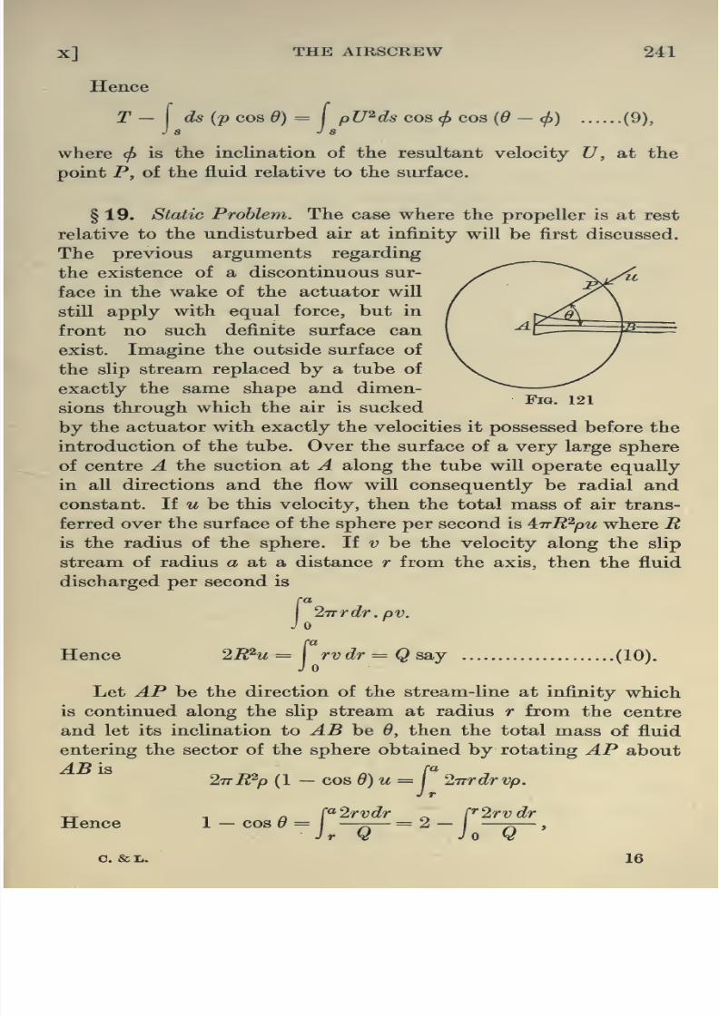
8/13/2019 Aeronautics in the 00 Cow Lu of t
http://slidepdf.com/reader/full/aeronautics-in-the-00-cow-lu-of-t 269/365
X] THE AIRSCREW 241
Hence
T- \ds{p cosd)=
I
pU^ds cos<l>
cos {6- cfi) (9),J s J s
where<f>
is the inclination of the resultant velocity U, at the
point P, of the fluid relative to the surface.
§ 19. Static Problem. The case where the propeller is at rest
relative to the undisturbed air at infinity will be first discussed.
The previous arguments regarding
the existence of a discontinuous sur-
face in the wake of the actuator will
still apply with equal force, but in
front no such definite surface can
exist. Imagine the outside surface of
the sHp stream replaced by a tube of
exactly the same shape and dimen-
sions through which the air is sucked
by the actuator with exactly the velocities it possessed before the
introduction of the tube. Over the surface of a very large sphere
of centre A the suction at A along the tube will operate equally
in all directions and the flow will consequently be radial and
constant. If u be this velocity, then the total mass of air trans-
ferred over the surface of the sphere per second is inR^pu where Ris the radius of the sphere. If v be the velocity along the slip
stream of radius a at a distance r from the axis, then the fluid
discharged per second is
Jo27rrdr.pv,
ra
Hence 2R^u =\rvdr=Qssiy (10).
J
Let AP be the direction of the stream-line at infinity which
is continued along the slip stream at radius r from the centre
and let its inclination to AB be 6, then the total mass of fluid
entering the sector of the sphere obtained by rotating AP about

8/13/2019 Aeronautics in the 00 Cow Lu of t
http://slidepdf.com/reader/full/aeronautics-in-the-00-cow-lu-of-t 270/365
242 AERONAUTICS IN THEORY AND EXPERIMENT [CH
giving cos^6l2=y,\ rvdr (11),
V'o
which expresses ^ as a function of r.
§ 20. Integration of Pressure over Sphere. Since the flow is
everywhere radial the horizontal components of the pressures on
the outside surface of the sphere are in equilibrium.
§ 21. Transference ofMomentum over Sphere and Slip Stream.
Eegarding the sphere as a whole as much momentum evidently
enters as leaves provided the flow be supposed to take place
with velocity u along the slip stream towards the centre of the
sphere. The correction for this is clearly of the fourth order of
small quantities. Momentum leaving along the slip stream
,2= 27rrdrpv^
Jo
rce in the hor
T= { '^irpr^dr (12).
Hence, since the total force in the horizontal direction is T, this
gives
If v^ be thehorizontal component of the velocity at radius r at
the mouth of the tube, i.e., the inflow velocity at the propeller
disc, then the total quantity of fluid entering is
r27rrdrpVj^ = 27rpQ (13),
JO
the total mass of fluid passing down the slip stream, where
rvdr (14),
^0
§ 22. If the propeller be of such a nature as to provide a
constant distribution of velocity across the section of the slip
stream, then this expression for the thrust becomes

8/13/2019 Aeronautics in the 00 Cow Lu of t
http://slidepdf.com/reader/full/aeronautics-in-the-00-cow-lu-of-t 271/365
X]'
THE AIRSCREW 243
The average velocity of inflow to outflow is thus
v^ _a^ _ area of cross-section of slip stream
V a^ area of propeller disc *
giving T = pA^Hi^/A = pKA^v^^ (16),
where A^ is the area of the propeller and l/K is the contraction,
i.e. the ratio of the area of the slip stream at an infinite distance
behind the propeller to the area of the propeller.
§ 23. Case of aPropeller
moving withTranslational Velocity
V relative to Still Air. As already stated the problem will be
approached by the more
convenient method of sup-
posing the propeller station-
ary and the air moving past
with velocity V at infinity.| a^^^^^^^b^=^^^^
It will be assumed, although
rigorously further proof is
required, that the velocity
at a great distance R from
the propeller at any instant
is compounded of a horizontal component F and a uniform
velocity u directed towards the centre of the propeller. This for
the moment may be considered tantamount to restricting the
nature of the propeller.
Accordingly the total transference per second of matter across
the sphere is inR^up + ira^pV excluding slip stream. The amount
leaving per second through the slip stream is
Fig. 122
27TTpdr{V+v),
Equating these
iTrR^up -\-7ra^pV= Tra^p V + 27rp I rvdr,
Jo
1 r«therefore ^ = ^1 ^^^^ = 2^2
(^'^)-

8/13/2019 Aeronautics in the 00 Cow Lu of t
http://slidepdf.com/reader/full/aeronautics-in-the-00-cow-lu-of-t 272/365
244 AERONAUTICS IN THEORY AND EXPERIMENT [CH
neglecting second order terms. The horizontal component of
this in the direction AB is (Pq + puV cos 6) cos 6 and this inte-
grated over the whole sphere becomes
27tR sin 6 . Rd6 {f^ + puV cos 6) cos 9
/,
27rR^.puVcos^dsmdde
= - IttR^uVp = - irrVp.Q.'
(18),
which is a finite quantity.
§ 25. Transference of Momentum over Sphere and Slip Stream.
The elementary annulus passing through P and perpendicular to
^5 is of area 27rR sin 6. Rdd; and hence the mass of fluid leaving
the annulus per second is
27rR sind.Rdd {V cos d-u)p,
since (F cos 6 — u) is the total radial velocity. The component
motion in the direction AB is V — u cos 6 and hence the momen-
tum transferred per second over the annulus in that direction is
27tR sin e.Rde.(V cosd - u) p {V - ucos d).
Integrating this over the whole sphere where d ranges from v to 0,
this becomes _ st^oYQ,
To this must be added — irpa^ (F + uf- since the above calcula-
tion has supposed this amount transferred through the slip stream.
The momentum issuing across the section at B in the slip streamis
{ '2'nrdrp {V -^vf = ira^pV^ + iirpV\
vrdr + 2'np\ ' vh dr.
Jo JO Jo
Hence the total momentum transferred per second over the whole
system in the direction AB is

8/13/2019 Aeronautics in the 00 Cow Lu of t
http://slidepdf.com/reader/full/aeronautics-in-the-00-cow-lu-of-t 273/365
X] THE AIRSCREW 245
Equating this to the forces acting in the direction AB on the
system ra
r -f
nVpQ = i-n-pVQ + 27rp|
v^rdr.
(20).T = 27rpVQ + 27Tp v^rdr
§26. Example 1. Suppose the velocity distribution in the
slip stream is parabolic in v across the radius, vanishing at r =
and r = a, then 12Q
to
which as can easily be verified satisfies the equation
T = 27rpVQ + 2'np .^^ f {a - rf r^dr.
.-. T^27rpV^-^+h27TpaH^,
where v is the average velocity of outflow.
HencelOF
24 A/(-.^a-']= 42F[-v/(l + 4-8ir«)-l],
where K = r^\c? and a = Tjirpr^V^.
Example 2. Suppose the velocity in the slip stream is constant
over the section, then
T = 27TpVQ + TTpv^a^,
ra
where Q = \vrdr = va^/2.
Jo
Hence v^ + vV - T/rrpa^ = 0,
giving V = -57 [V(l + 4:Ka) - 1].
Taking a = 0*5 and the contraction as 0-65, this gives in
example 1 v/F = 0-51,
and in example 2^/l^ = 0-53
/. ^-^=0-02F.
This provides a measure of the error involved in assuming, in
the first case where the velocity distribution was parabolic and

8/13/2019 Aeronautics in the 00 Cow Lu of t
http://slidepdf.com/reader/full/aeronautics-in-the-00-cow-lu-of-t 274/365
246 AERONAUTICS IN THEORY AND EXPERIMENT [cH
§ 27. As in the static case the average inflow velocity can be
obtained by equating the quantity of fluid passing across the
propeller disc to that passing down the slip stream per second,
either assuming the inflow constant, or varying across the disc
according to any empiric law of distribution. The details of
this may be left as an exercise, but it may be here stated that
if the distribution of the additional inflow velocity over the
propeller disc be assumed uniform, the conception that the rate
of discharge of energy into the fluid is maintained by the work
done upon the fluid by the propeller thrust alone is sufficient to
determine, along with the expression for the thrust already
derived, that the additional inflow velocity is equal to one-half
the additional outflow velocity. For a discussion of this point
the student is referred to papers by Froude in Arch. Inst. Nav.
^rcA. 1889 and 1911.
Assumingtherefore that the velocity of inflow,
assumed uni-form over the propeller disc, is given to sufficient accuracy by half
the outflow velocity, and since the latter can be calculated closely
enough by the foregoing methods in terms of the thrust the
propeller is required to furnish, it is no difficult matter to apply
these results immediately in the question of design. The thi*ust
is of course determined by the drag of the rest of the machine at
the given speed. Instead of each blade element meeting the air
with velocity ^/[V^ + {^Trrtif],
as given in § 12, the additional inflow velocity merely requires
to be superposed, and the resultant velocity takes the amended
form^[(y + ^/2)2 + {27Trn)^].
The corrected angle of attack is now given by
tana = (F + 'y/2)/277-m.
This determines the setting of the blade elements to give
maximum efficiency to each. In practice, since the application
of the inflow is of the nature of a correction, it is sufficiently
accurate to assume it a constant over the propeller disc.

8/13/2019 Aeronautics in the 00 Cow Lu of t
http://slidepdf.com/reader/full/aeronautics-in-the-00-cow-lu-of-t 275/365
X] THE AIRSCREW 247
blades is to be accepted as a satisfactory basis on which to found
conclusions regarding the performance and therefore the design
of a propeller, it would naturally be expected that corresponding
scale effect should be found in this case also. Each element of the
blade being a miniature aerofoil will experience its own particular
scale effect, and how these sum up undergoing mutual interference
must receive special investigation. From our previous information
on this subject some such effect is to be anticipated. In one
essential however the present case differs from that previously
discussed. The translational speed of an aerofoil rarely exceeds
150 ft. per sec. ; a propeller blade on the other hand. 8 ft. diameter
rotating at 1500 revs, per min., propels its tip through the air at
a speed of approximately 650 ft./sec. In the case of the aerofoil
it was assumed that the only properties of the air affecting the
forces were the density and viscosity. This is amply justified for
such comparatively low speeds by experiment, but for high speed
projectiles it has been shown that when the velocity approximates
to that of sound, another factor, namely the compressibility,
comes into operation.
Although, as already explained in Chapter II, the sharp rise
in the resistance coefficient takes place in the immediate neigh-
bourhood of the velocity of sound, compressibility effects make
themselves evident at much lower speeds. Without further
evidence leading to a contrary conclusion it will be necessary
to suppose that the thrust on a propeller may depend, in addition
to the viscosity and density, upon the compressibility of the
medium. For the present purpose this is best represented by
the velocity of sound which depends directly on that quantity.
How far both the compressibility and viscosity modify the
results, at the ordinary speeds of propellers, will be discussed
later.
§ 29. Suppose the propeller is given by a drawing, the
diameter of length I, to scale. The properties of the fluid through
which the propeller is moving that will affect the thrust developed
are the density p, the viscosity v and the velocity of sound in the

8/13/2019 Aeronautics in the 00 Cow Lu of t
http://slidepdf.com/reader/full/aeronautics-in-the-00-cow-lu-of-t 276/365
248 AERONAUTICS IN THEORY AND EXPERIMENT [CH
the magnitude of the thrust. Following along the lines of Chapter
IV, each term in its expression must be represented in the form
p'^vHyn^V^v^ (21).
A thrust being a force must have dimensions ML/T^ and the
above expression must likewise reduce to this. The dimensions
of (21) are
Equating powers of M, L and T,
P + y + X+2fjL=i,
^ + 8 + A+ fjL=2.
Hence « = 1,
^ =2~S-X-fji,
y = 2 + 8 - /x.
Expression (21) now takes the form
pvH^ {{vjln)-K{v/V)~^{vl/v)-^}.
Each term in the expression for the thrust will therefore have
the factor pvH^ and will depend in addition merely on the quan-
tities v/ln, v/V and vl/v.
An equivalent statement of this is
T = pvH^f[Vlln, v/V, vl/v] (22).
§ 30. If compressibility and viscosity effects are appreciable
to any extent at the speeds of ordinary propellers, this must be
the form that the expression for the thrust must take. An
attempt to proceed further along the lines previously developed,
by running two similar propellers of different diameters in two
different media, say air and water, at corresponding speeds of
translation and rotation, fails, for this would give
llh = v,VlvV„

8/13/2019 Aeronautics in the 00 Cow Lu of t
http://slidepdf.com/reader/full/aeronautics-in-the-00-cow-lu-of-t 277/365
X] THE AIRSCREW 249
easily seen that even if the corresponding translational and
rotational speeds were attainable, the thrust developed would
be too high for accurate measurement. To proceed further,therefore, it will be necessary to refer back to the equation for
the thrust in order to discover what modifying assumptions, if
any, may be made regarding the quantities there introduced,
without vitiating the correspondence to actual conditions. One
might suspect that, at such high speeds, the dragging effect due
to the viscosity of the air would be inconsiderable in comparison
with the dynamic pressures developed. If the speed, moreover,
sufficiently high to make the viscous forces negligible, is yet not
too high to bring in compressibility effects to any appreciable
extent, it might be legitimate to neglect both the compression
term v/V and viscosity term vljv in the equation (22). Whether
one is entitled to make such assumptions or not is purely a
question that must be settled by experimental evidence. If it
were so, then equation (22) would become
T = pvH^F (v/ln) (23).
§31. In 1906, D. W. Taylor published results obtained by
experiments in water on three sets of five similar propellers of
different diameters. It was found that for the same value of v/ln
the thrusts were proportional to vH^. E. Dorand in 1910, as the
result of tests on two similar propellers 2-5 and 4*3 metres in
diameter respectively, moving with a translational speed of 25
metres per second, found that the forces on the two propellers
likewise varied as the squares of the speed and diameter for the
same value of v/ln. This was later borne out in 1911 by Eiffel.
A comparison between a propeller two feet in diameter tested
on the whirling arm at the N. P. L. and a similar one 15 feet in
diameter tested on Messrs Vickers' whirling arm also showed
excellent agreement in this respect (1910-11). It would seem
therefore that ample evidence exists to conclude that, when
v/ln is kept constant, f{v/ln, vljv, v/V) reduces to a constant.
This is equivalent to stating that the terms vl/v and v/V have
8/13/2019 Aeronautics in the 00 Cow Lu of t
http://slidepdf.com/reader/full/aeronautics-in-the-00-cow-lu-of-t 278/365
250 AERONAUTICS IN THEORY AND EXPERIMENT [cH
§ 32. It will be remembered that the justification for assuming
the existence of a definite constant, pitch, for a given shape of pro-
peller lay in the fact that for all values of forward speed the thrust
was found to vanish at the same value of v/ln. This statement is
equivalent to saying that there is no scale efiect for p/l where pis the pitch and I the diameter.
Now s = 1 — v/np = 1 — vjln . l/p,
therefore v/ln = {I — s) p/l = constant x (1 — s) for similar pro-
pellers. Equation (23) now reduces to
T = pvH^F^{s) (24),
and it follows that for the same value of the slip the thrust
coefficient TjpvW is a constant. There is no scale effect for similar
propellers at the same value of the slip ratio. This implies that
if the thrust coefficient were plotted against slip for similar
propellers for all values of v and n, the points thus obtained should
all lie on a single curve. The same applies to the torque and
efficiency. Fig. 112, giving the results of a series of tests on the
same propeller at different speeds, which of course is exactly
equivalent to change of scale, brings out the foregoing con-
clusions.
Equation (24) and the corresponding equation for the torque
indicates that the thrust and torque coefficients may be regarded
as functions of s only and consequently they may be expanded
either in terms of s or what amounts to the same thing, in terms
of Vjnp. The coefficients in these expansions will of course
depend on the particular form of propeller blade but on nothing
else. Attempts to determine a simple form of expansion of this
nature have shown that in practically all cases they may be
written
1
F\3-l
i8..104 - 0-833 fn
\npj
V
jipj
8/13/2019 Aeronautics in the 00 Cow Lu of t
http://slidepdf.com/reader/full/aeronautics-in-the-00-cow-lu-of-t 279/365
X] THE AIRSCREW 251
§ 33. From the point of view of the element theory this
seems a startling conclusion. As already pointed out the existence
of scale effect for aerofoils had suggested the possibility of acorresponding effect with propellers and yet it does not appear to
exist, A general explanation however is not far to seek. The
student will easily verify by a simple calculation and by referring
back to Chapter VI that the value of vl for the elements most
effective for thrust, viz. about a quarter of the radius from the tip,
V being the speed of the element relative to the air and Uhe length
of chord, is already in all such cases sufficiently great to be beyond
the range of variation of Hft coefficient with vl.
§ 34. If aerodynamic considerations were the only effective
ones that required to be allowed for in propeller design, it is
evident that the limitations thus imposed would allow a moderate
amount of latitude in the selection of blade sections to satisfy
these demands*. There is, however, another aspect of the question
which is at least as important as the aerodynamical one on account
of the restrictions that are demanded thereby. It has not in-
frequently occurred in the history of aeronautics that serious
accidents have resulted from the snapping of a propeller in mid-air.
An analysis of these cases has brought to light several important
points. If the relative wind is not directly along the axis then, asthe propeller rotates, the thrust on a blade is not constant but
varies with its position. It is thus subjected to a periodic force
and it is evident that if the natural period of vibration of any
portion should correspond to the period of this external impressed
force resonance effects will be set up with possible serious con-
sequences. In the second place each element of the blade is
rotating at a comparatively high speed round the shaft and the
centrifugal forces so produced may reach a considerable value.
Unless the requirements of strength so demanded are satisfied
the propeller will snap. In addition to the centrifugal forces
there exists the direct pressure of the air on each section of the
blade and this likewise, because of the moment it produces,
modifications in the design.

8/13/2019 Aeronautics in the 00 Cow Lu of t
http://slidepdf.com/reader/full/aeronautics-in-the-00-cow-lu-of-t 280/365
252 AERONAUTICS IN THEORY AND EXPERIMENT [CH
an intelligent modification of a previous one of known perform-
ance, but certain general considerations based on the preceding
discussions may be used as a guide. In general the engine revolu-
tions, the maximum speed of flight of the machine and the thrust
required from the propeller are previously known. These factors
in themselves are of course not sufficient to determine the propeller
uniquely even if it were possible practically to do so, but it is
desirable to find a propeller with as high an efficiency as possible
to satisfy the requirements. From a knowledge of the thrust and
the speed of flight the value of the inflow velocity can be approxi-
mately estimated, and thus the speed of each element of the blade
relative to the air established. Practical experience has shown
that the distribution in thrust along the blade or the thrust
grading curve as it is called is in general a curve of the type shown
in fig. 123 where the area enclosed between it and the horizontal
Thrust Grading Curve.
Radius Trom Boss.
Fig. 123
axis is equal to the given thrust on the blade. A selection of aero-
foil sections must now be made such that when set in position at
various points along the blade they provide a thrust gradient
approximately equal to that given by fig. 123. At the same time
the area of cross-section of these elements must be so determined

8/13/2019 Aeronautics in the 00 Cow Lu of t
http://slidepdf.com/reader/full/aeronautics-in-the-00-cow-lu-of-t 281/365
X] THE AIRSCREW 253
with most conveniently from the tip towards the boss. It may
be remarked that if the thrust grading curve be so drawn as to
fall slowly towards the tip (see dotted line, fig. 123), the type of
propeller corresponding will be one of sharp tip and consequently
suitable for high speed work. In the same way a rapid fall towards
the tip corresponds to a square tipped blade as required for lower
speeds. Experience in design alone can indicate where modifica-
tions may be inserted in the resulting blade to remove any bad
features that result. One point may be noticed; by a suitable
alignment of the centres of gravity of the sections the bendingmoments due to wind forces may be made to operate in opposition
to those due to centrifugal forces. This produces what is usually
termed rake in a propeller. The effect of this, and in fact the whole
question of stresses, should be accurately worked out on the final
propeller for the whole flying range.
§ 35. It may appear that a considerable amount of the fore-
going analysis has involved assumptions more or less arbitrary
in character. The fact that the thrust grading curve shown in
fig. 123 is in general the type represented depends very largely
on the element aerofoil theory, while the latter itself is after all
not too well established. Interesting experimental evidence
approaching the problem from an entirely new angle is to hand
tending to confirm in a large measure much of what has gone
before. Some recent experimental work conducted by Dr T. E.
Stanton, National Physical Laboratory, indicates that from a
measurement of the pressure head at numerous points in the slip
stream the general streaming character of the motion here assumed
appears to be maintained. Measurements of the increase in
pressure head between pairs of points fore and aft of the propeller
disc and as close together as is practically possible is taken as an
estimate of the thrust per unit length of the propeller blade in
that neighbourhood. For a considerable number of propellers
for which the experiments were conducted a thrust grading curve
was thus derived and the result checked by integration of the curve
and comparison with actual thrusts measured. Ample confirma-

8/13/2019 Aeronautics in the 00 Cow Lu of t
http://slidepdf.com/reader/full/aeronautics-in-the-00-cow-lu-of-t 282/365
254 AERONAUTICS IN THEORY AND EXPERIMENT [CH X
§ 36. During flight the stresses brought to play upon the
blades give rise to a considerable amount of warping so that the
blade in operation differs from that as designed, involving a
consequent difference from the anticipated performance. Asufficiently accurate estimation of the magnitude of the warping
may be made from a knowledge of the forces on each portion of
the blade and the position of the centre of pressure on each
section. This latter point is usually assumed with sufficient
closeness to be the same as that on the corresponding aerofoil
of the same section. Permanent twisting of the wood, a com-
paratively common feature in propellers, cannot be allowed for,
of course, and is frequently responsible for great differences from
the estimated performances.
In the actual manufacture of blades great care is exercised to
ensure that the propeller disc is exactly balanced about its centre,
otherwise at the high speeds of rotation serious consequences
might ensue on account of the stresses brought into being by
vibration. For a high speed propeller if the centre of gravity
were in error by about 1/600 of an inch the centrifugal force
originated would be about 10 lbs., alternating in direction about
35 times per second.

8/13/2019 Aeronautics in the 00 Cow Lu of t
http://slidepdf.com/reader/full/aeronautics-in-the-00-cow-lu-of-t 283/365
PARTY
CHAPTER XI
STEADY MOTION IN FLIGHT
§ 1. The motion of a machine will be completely determined
by the forces that are brought to bear upon it, and the initial
conditions of motion. With the exception of the attraction due
to gravity these forces are purely aerodynamic, and as such are
determined by the speed of the machine at the moment relative
to the air, the shape of its parts, and by its attitude. For a
machine at rest there usually exists a vertical plane about which
the various parts of the aeroplane are symmetrically distributed.
It will shortly become apparent that steady linear flight is always
possible without affecting this condition of symmetry which,
however, would no longer exist for any type of motion that
necessitated say the turning of the rudder, or an alteration in
the setting of the wing-flaps. Strictly, a machine which only
possessed one propeller would require to have its centre of gravity
slightly displaced from the central position, or an equivalent
slight alteration in the wing-flaps, to counteract the propeller
torque, but for the present this will be neglected. The axis of the
machine, as usually understood, is a Hne in this plane of symmetry
through the centre of gravity and parallel to the propeller shaft,
but the termis
often loosely applied to the horizontal line throughthe centre of gravity in that plane.
For all practical purposes the propeller thrust may be taken
as acting through the centre of gravity although rigorously this
is not quite true. The pitching moment brought into existence
in the case where this does not hold will be assumed neutralised
by an adjustment of the elevator setting as already indicated in

8/13/2019 Aeronautics in the 00 Cow Lu of t
http://slidepdf.com/reader/full/aeronautics-in-the-00-cow-lu-of-t 284/365
256 AERONAUTICS IN THEORY AND EXPERIMENT [cH
conditions in which the pilot finds himself do not alter with time
the motion of the aeroplane will be defined as steady. Under these
circumstances, once the controls have been placed in position for
flight at any instant, no alteration of their setting should be
necessary to maintain the motion.
§ 2. A little consideration will show that this definition of
steady motion, involving constantly the same attitude to the
direction of gravity and to the relative wind, leaves only three
types of flight paths that could, in this sense, be regarded as
those of steady motion. These are
(a) Motion in a straight line.
(6) Motion in a horizontal circle,
(c) Motion in a vertical helix.
A conclusive proof that these are possible flight paths of
steady motion in still air would demand that it be shown that
it is possible to follow these paths with an aeroplane, controls
fixed, moving with constant speed. This will be brought out
as the subject develops.
§ 3. Motion in a Straight Line. Symmetrical Flight. It will
be assumed that the machine is flying symmetrically with regardto the vertical plane containing the line of flight. This is tanta-
mount to stating that there is no yaw or roll, and that the direc-
tions of the rudder and relative wind are the same. The thrust Tfor all practical purposes may be supposed acting along the flight
path and through the centre of gravity of the machine. Since the
only other forces beyond this are the weight W, and the resultant
air force R whose components are L and D respectively acting
perpendicular to and along the flight path, R must also act
through the centre of gravity in order that there may be no
resultant moment to alter the aspect of the machine. Resolving
forces along and perpendicular to the flight path, fig. 124,
m's=T -D-W sin d,

8/13/2019 Aeronautics in the 00 Cow Lu of t
http://slidepdf.com/reader/full/aeronautics-in-the-00-cow-lu-of-t 285/365
XI] STEADY MOTION IN FLIGHT 257
For future work it will be convenient to express L and Dthe total lift and drag on the machine including that on the
wings in the form L ^ pAkiV^ and D = pAk^V^, where A is thearea of the wings, ki and ka may now be regarded as lift and drag
coefficients for the whole machine. Practically ki differs little from
Ki since the wings furnish almost the entire lifting force for the
machine. Remembering that
L = AkipV\
where V is the velocity at the moment, equation (2) then gives
^-A^) <*
It follows at once that for a given angle of attack, F is constant
so long as 6 is constant, and conversely. Straight line flight,
therefore, involves constant speed of flight. For a given velocity
and angle of flight path, taking /9 as constant, this equation likewise
determines the lift coefficient and therefore the angle of attack.
Fig. 124
Corresponding to each angle of attack there is a definite elevator
setting in order that there may be no pitching moment on the
machine. If 6 be small as it usually is except for steep dives,
the speed of flight determines the elevator setting, and vice versa.
A clear realisation of this conclusion will smooth the way towards
an understanding of much of the work that follows.

8/13/2019 Aeronautics in the 00 Cow Lu of t
http://slidepdf.com/reader/full/aeronautics-in-the-00-cow-lu-of-t 286/365
258 AERONAUTICS IN THEORY AND EXPERIMENT [CH
§ 4. Gliding Flight. If the propeller be switched off, the
machine will commence to glide. The gliding angle will be given
by Dtan^= --^ (4),
obtained from equations (1) and (2) by putting T = 0, where
D now includes the propeller resistance. In cases of emergency,
it is often required to alight when flying over a stretch of ground
not suitable for landing. Under such conditions ghding at such
an angle as would give the minimum velocity of fall affords the
pilot the best opportunity of selecting his landing point. The
minimum angle of glide will of course occur when tan ^ is a mini-
mum, that is at the flying position corresponding to maximum
LjD. The velocity along the path will as before be given by
equation (3). A machine may therefore glide from any point to
earth down any straight line situated within a cone of semi-
vertical tan-^ (iy/Z))jj^g^^ . Rigorously, however, the angle of glide
corresponding to the slowest velocity of drop is not exactly the
minimum angle of glide but lies close to that position. The student
may easily verify this by determining the value of LjD that makes
F sin 6, the velocity of drop, a minimum, where F is given by
equation (3).
§ 5. Vertical Dive. The machine is assumed to be diving
vertically under the action of gravity and the thrust of the
propeller. Since there must be no forces perpendicular to the
line of flight the angle of attack must be that corresponding to
zero hft coefficient, supposing the propeller to act directly along
the flight path. The equation of motion will then be
my=W +T -D (5).
This equation may be integrated from a knowledge of T and Das a function of the velocity, but for our present purpose it will
be sufficient to deal in some detail only with the case where the
aeroplane falls purely under the action of gravity, the propeller
being switched off. Putting T = 0, K = pAk^, where ka is the
drag coefficient in this case corresponding to zero lift, a = m/K

8/13/2019 Aeronautics in the 00 Cow Lu of t
http://slidepdf.com/reader/full/aeronautics-in-the-00-cow-lu-of-t 287/365
Xl] STEADY MOTION IN FLIGHT 259
Hence az j- = ^ — z^.
a d{z^)jdy.
2^-
Suppose the initial velocity of drop is V ft./sec. so that y =
when z = F, it is easily found that
2 ^ P'-fhence f = ^- {^^ - V^) e-^v/-.
The velocity therefore tends to the limit jS, and after falling
a distance y the speed is given by
The limiting speed corresponding to ?/ ^ oo is
^ = ^/(WlpAl,) = SV[(h)u^.M (6),
where S is the landing speed.
A simple calculation shows that the limiting velocity of a
normal machine lies in the neighbourhood of 200 to 250 ft. per
second, which it will practically attain after falling a few hundredfeet, supposing the initial velocity of fall to be approximately
the normal speed of flight. In passing, it may be mentioned that
this is not the maximum velocity that may be attained by falling
under gravity. This is reached at such an angle of attack as makes
^? + ^/ ^ minimum.
The limiting speed is practically unaltered by switching on
the propeller, since the latter would then be running at a small
value of slip.
§ 6. Asymmetric Straight Line Flight. It has been assumed
in the previous discussion that the aeroplane in its steady linear
motion was symmetrically situated with regard to a vertical

8/13/2019 Aeronautics in the 00 Cow Lu of t
http://slidepdf.com/reader/full/aeronautics-in-the-00-cow-lu-of-t 288/365
260 AERONAUTICS IN THEORY AND EXPERIMENT [cH
the further question would then be suggested, whether these two
types of equilibrium differ in respect of stability, but such a
discussion must be postponed till the next chapter.
That steady asymmetric flight is possible can be seen from
a comparatively simple consideration. Suppose the machine
moving through the air at a certain angle of yaw. There will
be brought into existence in addition to the lift and drag forces
a component of the resultant force perpendicular to both of these.
In order to neutralise this cross-wind force, the machine wouldrequire to be banked. There will thus be three quantities, viz.
the angle of pitch, the angle of bank or roll, and the angle of yaw,
whose variations are at our disposal to satisfy the conditions of
equilibrium.
Resolving the forces on the machine along any three directions
three independent equations will be obtained which will suffice
to determine these quantities. The elevators, rudder and wing-
flaps must be supposed set in the positions required to destroy the
turning moments about the three directions.
The state of motion here discussed is typical of certain occur-
rences in flight technically known as side-slipping. When the axis
of the machine is not in the same vertical plane as the axis of
flight so that the relative wind is not parallel to the plane of
symmetry the machine is said to side-slip.
§ 7. Performance Curves. Performance curves describing the
characteristics of the machine at various speeds are usually
plotted on the assumption that the atmosphere is of uniform
density. The fact that the air forces and the propeller thrust
depend directly on p the density of the air indicates clearly thatthe performance curves will not be complete unless allowance
is made for variations in this quantity. The mere fact that at a
height of 10,000 ft., a not uncommon flying altitude, the density
has already dropped to 0-7 of its value at the earth's surface,
is a sufficiently clear indication that alterations in the performance
curves due to this cause are of considerable importance.

8/13/2019 Aeronautics in the 00 Cow Lu of t
http://slidepdf.com/reader/full/aeronautics-in-the-00-cow-lu-of-t 289/365
XI] STEADY MOTION IN FLIGHT 261
constant, the ordinates of curve 4 are practically proportional
to those of 3 slightly modified however by the inclusion of pro-
peller shp stream. This is specially marked at high speeds. Theproduct of such ordinates of curve 3 by the corresponding velocity
gives the power required to overcome the resistance, also at
ground level. This is plotted in fig. 125 in the same diagram as
the total horse-power available from the propeller. The difference
between the ordinates of tfiese two curves for any speed furnishes
a measure of the horse-power available for climb, etc. The upper
point of intersection determines the maximum speed of horizontal
flight. The difference between the two resistance curves for gliding
and for flying is due to the slip stream of the propeller.
2 350 70r
3 300 60
.j; 4 0^250 50
^5 ^200 140
V)6.5150^30
^7 100 20
50 10
60 Ft./Sec. 70
40 M.RH.
80
Velocity60 70
Fig. 125
§ 8. The air forces are proportional to pV^ and since at
higher altitudes for a given angle of attack the same lift, viz.
pV^Aki, must be maintained, a comparison between performance
curves at various levels must be made at corresponding values
of pV^. It will therefore be convenient to plot the quantities con-
cerned on a Fy'/o base where p is assumed unity at ground level.
On this base the resistance curve of a machine will not change with
altitude. This is not so however with the horse-power curves.

8/13/2019 Aeronautics in the 00 Cow Lu of t
http://slidepdf.com/reader/full/aeronautics-in-the-00-cow-lu-of-t 290/365
262 AERONAUTICS IN THEORY AND EXPERIMENT [CH
Since at the higher altitudes the velocity of flight must be
increased to maintain the lift, the propeller will of necessity be
working at a lower slip,- and the thrust will drop unless the
revolutions be increased proportionately to give the same thrust
and slip. At the same time the energy given to the engine has
fallen on account of the smaller mass of air taken up by the
cylinder at each stroke for these lower densities, and therefore
the horse-power delivered up will fall off for the same revolutions,
approximately as the density.
§ 9. In fig. 126 is plotted horse-power available from engine
at ground level against engine revolutions (curve A). Curve B
representing the engine
horse-power at a height
where the density is p is
derived by multiplying each
ordinate of A by p/pg . The
system of curves,C, D,E, etc.
giving the propeller torque
horse-power against revolu-
tions at various constant
speeds, intersect curve B at
X, Y, Z, etc., and accord-
ingly fix the torque horse-
power, forward velocity and revolutions. From these the slip and
efficiency are of course at once obtained and by multiplying the
/?ei/s. per Min.
Fig. 126

8/13/2019 Aeronautics in the 00 Cow Lu of t
http://slidepdf.com/reader/full/aeronautics-in-the-00-cow-lu-of-t 291/365
XI] STEADY MOTION IN FLIGHT 263
immediately calculable and plotted in fig. 127 on a V^/p base by
multiplying the ordinate of the horse-power curve at ground level
Once more the horse-power available for further climb at
each speed and the greatest minimum speed of flight can be
derived. It is manifest that as the density diminishes these,
curves include a constantly decreasing area until ultimately a
point is reached at which the maximum and minimum speeds
of flight coincide and there is no horse-power available for further
chmb. This determines the highest altitude to which this machine
can ascend. This height is usually termed the ceiling. It can be
further increased by special treatment of the engine, for example
by supplying it with oxygen under pressure, a process usually
known as doping the engine.
§ 10. Steady Horizontal Circular Flight. Consider the effect
of turning the rudder of a machine in steady horizontal flight.
There is immediately brought into
play a force on the rudder tending
to displace the centre of gravity
of the machine laterally. This is
quickly nullified, however, by the
factthat a
rotation about the
centre of gravity is set up simul-
taneously by the moment of this
same force about that point, with
a consequent cross-wind force pro-
duced by the keel surface of the machine.
This cross-wind force supplies the acceleration towards the
centre of curvature of the flight path, necessary to maintain the
motion. Unless the machine were in this yawed position this
force would not come into existence. Fig. 129 illustrates the
successive positions adopted by the aeroplane in its flight. At P^
the machine is flying normally along a straight path and the rudder
has just been turned, thus bringing into existence a force on the
rudder in the direction as indicated. At P2, to which position
Force on Ri^dden
Fig. 128
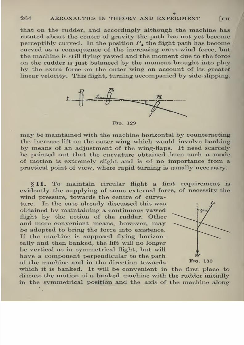
8/13/2019 Aeronautics in the 00 Cow Lu of t
http://slidepdf.com/reader/full/aeronautics-in-the-00-cow-lu-of-t 292/365
264 AERONAUTICS IN THEORY AND EXPERIMENT [CH
that on the rudder, and accordingly although the machine has
rotated about the centre of gravity the path has not yet become
perceptibly curved. In the position P^ the flight path has becomecurved as a consequence of the increasing cross-wind force, but
the machine is still flying yawed and the moment due to the force
on the rudder is just balanced by the moment brought into play
by the extra force on the outer wing on account of its greater
linear velocity. This flight, turning accompanied by side-slipping,
Fig. 129
may be maintained with the machine horizontal by counteracting
the increase lift on the outer wing which would involve banking
by means of an adjustment of the wing-flaps. It need scarcely
be pointed out that the curvature obtained from such a mode
of motion is extremely slight and is of no importance from a
practical point of view, where rapid turning is usually necessary.
§11. To maintain circular flight a first requirement is
evidently the supplying of some external force, of necessity the
wind pressure, towards the centre of curva-
ture. In the case already discussed this was
obtained by maintaining a continuous yawed
flight by the action of the rudder. Otherand more convenient means, however, may
be adopted to bring the force into existence.
If the machine is supposed flying horizon-
tally and then banked, the lift will no longer
be vertical as in symmetrical flight, but will
have a component perpendicular to the path

8/13/2019 Aeronautics in the 00 Cow Lu of t
http://slidepdf.com/reader/full/aeronautics-in-the-00-cow-lu-of-t 293/365
Xl] STEADY MOTION IN FLIGHT 265
the flight path. If <^ be a small angle of bank, W the weight and
L the lift, then for horizontal equilibrium of the machine
W = L cos <f>.
The horizontal force in the direction of bank equals L sin </>. This
will supply the force required to drive the centre of gravity
initially on a circle of radius R where
-.^^Lsm^.
The aeroplane as a body will thus commence to move in acircle,
but since no turning moment has been brought into play the axis
of the machine will not continue to coincide with the flight path.
Side-slipping will therefore immediately take place. As a con-
sequence of the circular motion, the outer wing, moving more
rapidly than the inner, experiences a greater lift and drag and two
effects immediately become apparent. In the first place the angle
of bank will tend to increase, and in the second place this increased
drag will set up a turning moment about the centre of gravity
augmenting the yaw. The side-slip will be intensified. This will
continue until an equilibrium position, if any, is reached deter-
mined by the increasing pressure on the tail fin. The tendency
towards increased banking may of course be neutralised by an
adjustment of the wing-flaps. It is obvious that complete motion
in a circle, that is without side-slipping, could not here be obtained
without the machine being turned by swinging over the rudder to
bring the axis along the flight path.
§ 1 2. Generally the above considerations indicate that circular
flight may be executed either by the action of the rudder alone
or by banking. In both cases, however, side-slipping will result
and this effect, as will shortly be rigorously shown, will not be
eliminated unless both the rudder and wing-flaps are utilised.
Under such circumstances the turning will be most rapid, and the
axis of the machine will remain continuously along the flight path,
but unlike steady horizontal flight the symmetry will be destroyed.
It must be specially emphasised that the main function of the

8/13/2019 Aeronautics in the 00 Cow Lu of t
http://slidepdf.com/reader/full/aeronautics-in-the-00-cow-lu-of-t 294/365
266 AERONAUTICS IN THEORY AND EXPERIMENT [cH
and other controls having been set to the appropriate positions
to maintain the steady turning. The angle of bank being </> the
equations of motion become
Lsmcf>^ W/g.V^/R (7),
Lcoscf> = W (8),
D-=T (9),
neglecting the relatively small components of the force on the
rudder and the difference in lift and drag on the two wings due
to the fact that the outer wing is moving more rapidly than the
inner. For a given speed and flight path, the requisite angle of
bank is immediately given by
tan<f>= V^/gR.
It follows at once that to fly in a circle of small radius with a
given velocity the angle of bank must be steep, but equation (8)
indicates at the same time that in order that the machine will
not drop the lift must be immediately augmented, demanding
an increased angle of attack compared with horizontal flight.
This involves a greater expenditure of horse-power.
§ 13. In general performance curves for any machine usually
give a measureof
the horse-power required to maintainhorizontal
flight at various speeds. From such a curve the corresponding
horse-power required to maintain circular flight may easily be
derived. In either case the horse-power is expended in overcoming
the drag. Comparing the two cases, horizontal flight at velocity V
and circular flight at the same speed but necessarily at a different
angle of attack,
H, = TJ = DJ = Ap (U ys (10)
for circular flight,
H^ = T,V = D,V = Ap {ka), V^ (11)
for horizontal flight.
Therefore H, = H^{k,)J{h)2 (12).

8/13/2019 Aeronautics in the 00 Cow Lu of t
http://slidepdf.com/reader/full/aeronautics-in-the-00-cow-lu-of-t 295/365
XI] STEADY MOTION IN FLIGHT 267
Suppose the machine flying in straight line flight with velocity
Fj at the angle of attack corresponding to the lift coefficient {ki)^ ,
that of the previouscircular flight, then
and W=Ap{ki)2V\
as before, where F is the horizontal flight equivalent, from this
point of view, to the circular flight.
Therefore {Jci)J{ki)^ = V^/V.^
hence Fj = FV^os^ (14).
If Hj' and Fg be the horse-powers required to drive the
machine in horizontal flight at velocities F^ and F respectively,
then H, = D,V = Ap {k,),V^
and jy/ = Z)iFi=^pfe)iFi3,
therefore {kMka)2 = ^i7^2 • F^/F^^
= F//^2.1/(cos<^)t.
This gives finally, using (13),
H, = H^'l(coscf>)' (15),
expressing the horse-power required to maintain the machine in
horizontal circular flight, of radius R and velocity F, in terms of
the horse-power required to drive the machine at the equivalent
velocity of horizontal flight
Vi= V a/cos (/>
= Vlil+ V^lg^R^)i (16).
The method of obtaining the horse-power curve for circular
flight is at once obvious from these formulae. The horse-power
for horizontal flight at velocity V-y/coscj) is divided by (cos</>)-^
and plotted on a velocity base at abscissa F.
In fig. 131, AD represents the horse-power available from the
propeller of a particular machine, and CB the curve giving the
horse-power required at various speeds for horizontal flight. The
curves of the type PQ representing the horse-power for circular
flight at various radii and speeds are obtained by the method

8/13/2019 Aeronautics in the 00 Cow Lu of t
http://slidepdf.com/reader/full/aeronautics-in-the-00-cow-lu-of-t 296/365
268 AERONAUTICS IN THEORY AND EXPERIMENT [CH
except in the cases about to be mentioned, fix the minimum
radius of the circle at the velocity determined by M. If CN is
the locus of the points on each curve corresponding to maximumlift coefficient, none of the curves of the system can possibly go
beyond CN, and the.points of intersection of this system with this
line determine the minimum radii of circular flight at the cor-
responding speeds within the range limited by C and N. The
minimum possible radius corresponds to the curve touching AB,
in this case approximately 185 ft.
150 I Q. BBIsT
' r-KA-.
r-^m w A °/J,^^ /Cm ^^ A #^ ^yW / \ /
'/\-
100 / /
^
/ V // / // ^ y
y
Ay / ^ r/ /
/^
^y y\/ ^ ^ ^y 1
50 r*x
/,
•' ^^ ^y
Vv
_j2Ij
]^S
70 80 90 100 110 120 130 140 150 160 170 180 190
Velocity in FV/Sec.
Fig. 131
§ 14. It must be remembered that in the type of flight
contemplated it is necessary that the angle of attack of the
machine should correspond to a higher lift coefficient than that of
horizontal flight at the same speed, in order to sustain the weight
when banked. The corresponding drag coefficient would then
be greater or less than that of horizontal flight according to

8/13/2019 Aeronautics in the 00 Cow Lu of t
http://slidepdf.com/reader/full/aeronautics-in-the-00-cow-lu-of-t 297/365
XI] STEADY MOTION IN FLIGHT 269
that the system of constant radii curves ultimately cuts ADat a series of points, such as D, corresponding to a higher speed
than that at B, viz., the maximum speed of horizontal flight.
The diiierence is however comparatively small, in this case not
amounting to more than two miles per hour.
Fig. 132 gives, on the same diagram, the maximum curvature
of the path possible, the maximum angle of bank and the angular
velocity for various speeds.
A rigorous treatment of the problem of circular flight would
be extremely complicated owing to the introduction of certain
imperfectly known factors dealing with the variation in wind
forces along the wings due to the rotation.
TO 80 90 100 no 120 130 140 150 160 170 180 190
Velocity in Ft/Sec.
Fig. 132
§ 15. Spiral Flight. It has just been demonstrated that
circular flight without side-slipping will take place when both
the rudder and banking are made use of. If the machine be
supposed at the same time to drop or climb with constant velocity,
the path traced out will be a helix. It is proposed to determine
the relations that exist between the forces operating, and the

8/13/2019 Aeronautics in the 00 Cow Lu of t
http://slidepdf.com/reader/full/aeronautics-in-the-00-cow-lu-of-t 298/365
270 AERONAUTICS IN THEORY AND EXPERIMENT [CH
have been fixed in the appropriate positions so that the axis of the
machine is along the flight path and neglecting the relatively small
cross-wind force on the rudder. Defining the angle of bank bythe inclination of the plane of symmetry to the vertical plane
through the axis of the machine, and resolving forces along the
tangent to the path, along the normal and binormal, fig. 133,
the equations of motion become
T-D= Wsind (17),
Zcos^^ Tf cos^ (18),
Lsm<l>= Wlg.V^IR (19),
since the normal is along the radius of the cylinder and the
radius of curvature of flight path = i? = r/cos^ d.
Tangent Plane
to Cylinder.
Fig. 133
It follows that the angle of bank for a given helix defined by
R and 6 and for a given velocity F is determined from
tan(^= V^lgR cose (20).
From equation (18) the lift coefficient for this flight becomes
ki = W/pAV^ . cos 9/cos (f>.
Writing equation (17) in the form

8/13/2019 Aeronautics in the 00 Cow Lu of t
http://slidepdf.com/reader/full/aeronautics-in-the-00-cow-lu-of-t 299/365
XI] STEADY MOTION IN FLIGHT 271
horse-power necessary to overcome the drag at various velocities
in spiral flight can be derived from the horse-power curve for
horizontalflight.
§ 16. Let H^ = this horse-power during spiral flight and
j^2 = the horse-power for horizontal flight at the same speed,
Moreover L cos <^ = W cos 6,
hence W = Ap {ki)-^^ V^ cos <f>lcos 6,
and W^Ap{k,)^V^
for horizontal flight at the same speed.
Therefore (^1)1/(^1)2 = cos ^/cos(f>.
If Fi be the horizontal velocity corresponding to the same angle
of attack as in the spiral flight, then
W = Ap{k,\V,^
therefore V^/V^^ = {ki)J{ki)2 = cos 6'/cos cf>,
so that Fi= FVcos</>/cos^ (22).
Now H^ = DJ = Ap (k,)^ F3.
Let H^' = the horse-power required for horizontal flight atthe equivalent velocity Fj, then
therefore
{ka)il(K)2 = H^'yW2Vi^ = H.'/H^ . (cos d/cos <^)i
Hence finally ^1 = ^Z (cos ^/cos 0)^ (23).
Since 6 is supposed given and (/> has been determined in terms
of 6, F, and R, this equation provides a means of obtaining the
horse-power to overcome the drag during spiral flight at velocity
F in terms of the corresponding horse-power for horizontal
flight at the velocity F Vcos ^/cos 6. This will provide a system
of curves for all values of R for each value of 6. By the same

8/13/2019 Aeronautics in the 00 Cow Lu of t
http://slidepdf.com/reader/full/aeronautics-in-the-00-cow-lu-of-t 300/365
272 AERONAUTICS IN THEORY AND EXPERIMENT [cH
of horse-power for climbing beyond that required for circular flight
so that the minimum radii of curvature for spiral climbing will be
greater than that for circular flight.
It is clear that the problem of spiral flight in its most general
form includes as particular cases those of steady circular and
straight Une flight. The deduction of the results obtained in these
two previous cases from the preceding discussion will be left
as an exercise to the student and a comparison of the results in
these three cases is well worth making. The concluding remarks
of § 14 apply with equal force here and it is due to this that the
problem of steady vertical spin is not included in the above
discussion.
§ 17. Landing. Normally when a pilot has arrived above
his landing ground he will make a spiral glide to earth, that is
he will fly in a spiral without propeller thrust. On approaching
close to the ground however, in order to avoid meeting it too
sharply he usually flattens out his flight path by quickly switching
on his propeller. It occurs not infrequently that omission of this
point involves disastrous consequences to the under-carriage.
The landing will be most efiiciently executed if carried out at a
minimum velocity relative to the ground. This is best obtained
by landing up-wind at the maximum angle of attack. Immediatelyon touching, the propeller is switched off, and the speed of the
machine reduced by pulling the tail down until the skid drags.
It is important to notice that while the machine is in the air its
speed is not ultimately increased by switching the propeller on
but the flight path is merely flattened out. Such an increase could
only occur by an alteration in the elevator setting. If in flattening
out the flight path the angle of attack be increased, the propeller
not having been switched on, so that the speed of the machine
is reduced below that required for sustentation before contact
is made with the ground, the aeroplane will simply drop to earth
and the bad landing thus produced is known as pancake landing.
Should the angle of attack be increased so quickly that the nose

8/13/2019 Aeronautics in the 00 Cow Lu of t
http://slidepdf.com/reader/full/aeronautics-in-the-00-cow-lu-of-t 301/365
XI] STEADY MOTION IN FLIGHT 273
§ 18. Starting. As with landing, starting is most efficiently-
executed up-wind, in which position for the same ground speed,
the speed relative to the wind is greatest. The elevators are
set in the position for minimum drag of the machine, and the
propeller having been switched on the aeroplane starts off along
the ground. When the speed has passed the landing speed the
elevators are set for flight at a higher angle of attack, the machine
takes the air, and rises.
§ 19. The preceding discussions have been confined almost
entirely to questions that arise when the aeroplane is moving
into air at rest, or those that can be reduced to this, as for example
flight in a steady wind. A complete treatment of the more general
problem of the behaviour of a particular machine under variable
conditions such as the effect upon its motion of a series of gusts
is a subject of considerable complexity. One particular class of
cases however is of extreme practical importance. Suppose the
machine moving with steady motion in a particular path be
subjected to a slight disturbance, the question naturally arises
whether the aeroplane will return ultimately to the same con-
ditions of flight, and whether it is possible so to design the machine
that this desirable result will be achieved. This is concerned with
the problem of stabiHty.

8/13/2019 Aeronautics in the 00 Cow Lu of t
http://slidepdf.com/reader/full/aeronautics-in-the-00-cow-lu-of-t 302/365
CHAPTER XII
STABILITY—MATHEMATICAL THEORY
§1. General Discussion. The problem of stability treats
generally with the effect of a disturbing impulse upon any me-
chanical system, and more particularly with the state of motion
that results from it. For convenience the subject may be divided
into two parts. Under the first heading there fall to be considered
those cases in which the mechanical system existed previous to
the disturbance in a state of static equilibrium. This might be
typified by the case of a pendulum, initially as rest, and upon
which is impressed a slight impulse. Statical stabiHty, as here
illustrated, will concern itself with the future motion of the
pendulum and decides whether the original condition of equilibrium
will ultimately be reinstated. Aeronautics dealing usually with
machines in flight and not at rest, this type of stability will be
ignored. In the second place a state of motion under the existing
forces having been proved possible, at some point in its history
a sHght disturbing force is impressed on the system. Dynamical
stability deals with the resulting motion and concerns itself with
the question as to whether on the removal of the disturbing force
the original state of motion will be eventually resumed. The
meaning of the problem and the method of attack is illustrated
by the following example from the dynamics of a particle.
§2. Suppose a particle of mass m sliding from rest under
gravity down the lowest generator of a smooth cylindrical tube
of circular section filled with fluid inclined at an angle a to the
horizontal. It is required to determine its subsequent motion

8/13/2019 Aeronautics in the 00 Cow Lu of t
http://slidepdf.com/reader/full/aeronautics-in-the-00-cow-lu-of-t 303/365
CH XIl] STABILITY—MATHEMATICAL THEORY 275
R along the radius of the tube. The resulting acceleration down
the generator will be dvjdt, and hence
dvm
J-= mg sin a — Kmv (1),
.*. dvjig sin a — kv) = dt,
and the velocity is given by
v={glK)^ma.{l-e-^%
since v = where t = 0. Since after the lapse of some time
e-^' becomes negligible, the velocity reaches the terminal value
g sin ajK.
Horizontal.
Fig. 134
Equation (1) contains a full statement of the history of the
particle. Suppose after a time t, it receives a small impulse
giving it an additional velocity u per-
pendicular to its path, so that at time t
it occupies the position P and has a
component of velocity rd along the cir-
cumference of the cross-section (fig. 135).
The forces acting on the particle along
the tangent are now KmrO due to the
fluid, and mg sin a sin 6 due to the
weight. Writing the component accele-
ration along the tangent as rS the equa-
tion of the component motion round the
circle becomes
mr'd = — Kmrd — mg sin a sin 9.
Assuming the displacement 6 is small this takes the form
Tngsina,
Fig. 135

8/13/2019 Aeronautics in the 00 Cow Lu of t
http://slidepdf.com/reader/full/aeronautics-in-the-00-cow-lu-of-t 304/365
276 AERONAUTICS IN THEORY AND EXPERIMENT [CH
where A^ and Ag are the two roots of the equation
X^ + KX + g sin ajr = 0,
i.e., A = - Z/2 ± \/(^74 - g sin a/r).
Four cases fall to be considered.
(a) K^ji > g sin a/r. This involves that the two values for
A are real and negative, so that the small angular displacement
from the lowest generator gradually diminishes to zero according
to equation (2) and the motion tends to become the same as
that before the displacement. The motion of the particle in this
case, where it tends and finally does return to its previous motion,
is an illustration of a certain form of stability.
Fig. 136
(b) K^ji < g sin ajr. The quantity determined by the root
• sign is now purely imaginary, and the expression for 6 takes the
form
where
= e~^*'^ (Ai cos qt + B^ sin qt),
The angular displacement of the particle now oscillates about
the lowest generator in constantly decreasing amplitudes, until
finally it dies out. This likewise illustrates a particular type of
stability.
The variation in 6 with time is shown in fig. 136 for the two

8/13/2019 Aeronautics in the 00 Cow Lu of t
http://slidepdf.com/reader/full/aeronautics-in-the-00-cow-lu-of-t 305/365
XIl] STABILITY—MATHEMATICAL THEORY 277
These may be obtained either directly or by simply changing the
sign of r in the above equations so that
A = - ^/2 ± V(^74 + g sin a/r).
It is obvious that there is always one value for A which is positive,
and accordingly the expression for B involves the term 6^** where
Ai is positive. B therefore increases with time, and the path of
the particle tends continually to diverge from the highest gene-
rator; the original motion will never be resumed. This is an
illustration of instability, and the continuous divergence fromthe path of equilibrium is represented in fig. 136.
(cZ) When the particle is in motion down a line of greatest
slope of an inclined plane of infinite extent, the equations of
motion can be similarly derived, either as a limiting case of the
above or directly. If as before the particle be given a small
impulse perpendicular to its path so that at any time it is dis-
placed a distance x from the original line of motion, then its
acceleration in that direction is given by
mx = retardation
= — mlix.
Hence a? = ^ + Be-^^ and x = — KBe~^*.
As time goes on the particle tends to return to its original motion,
since x dies out, but moves ultimately along a line parallel to,
but displaced a distance A from, the original path. As far as
the actual path is concerned the stability is of the neutral type,
but, since the speed is ultimately of the same magnitude, and in
the same direction as that which would have existed without
the disturbance, as far as the velocity is concerned this is a case
of stability.
§ 3. Before leaving this example and approaching the
question of stability from a more general point of view it must
be remarked that the criterion for stability here enunciated
amounts to the statement that only when the values of A in the

8/13/2019 Aeronautics in the 00 Cow Lu of t
http://slidepdf.com/reader/full/aeronautics-in-the-00-cow-lu-of-t 306/365
278 AERONAUTICS IN THEORY AND EXPERIMENT [CH
§ 4. In seeking for a sufficiently inclusive definition and an
adequate criterion for stability, the effects of every possible case
of disturbance upon various types of motion must be considered.
An analysis of the nature of the disturbances leads immediately
to a separation under two heads. In the first place the mechanical
system, be it a particle or such a complicated mechanism as an
aeroplane or even such a medium as a fluid, may be supposed to
undergo a displacement of infinitely small amount. The question
for investigation is whether the resulting motion will tend to
approach or diverge from that previously existing. It must be
pointed out that if the original equations of motion are continuous
functions of position, velocity, etc., an infinitely small displace-
ment, even in the case where the motion tends to diverge, will
never attain a finite value in a finite time. Thus, suppose a thin
rod balanced vertically on an end is subjected to a displacement
of infinitely small amount from that position of unstable equili-
brium, then the moment brought into play tending to increase
the displacement is infinitely small, increasing at a finite rate
and therefore never becomes finite. At the same time the mere fact
that the displacement increases in magnitude is normally taken
as an indication that the position is one of instability, the implica-
tion being that if a small finite disturbance were impressed upon
it, a similar continuous increase in displacement would follow.
This consideration immediately suggests a second classification
of stability in relation to disturbance. It is conceivable, and
numerous illustrations are easily found, that the mechanical
system might be stable in this sense to displacements of infinitely
small amount or even of finite amount, but unstable to those
exceeding a certain magnitude. It would be necessary, in such
an event, to state accurately the nature of the disturbance, as
for example, that the system was stable to a particular displace-
ment of amount 8. As far as the application of any investigation
of this problem to practice is concerned, as in the case of an
aeroplane in flight, it is evident that it is really the second view
of this question which approaches most nearly to actual con-

8/13/2019 Aeronautics in the 00 Cow Lu of t
http://slidepdf.com/reader/full/aeronautics-in-the-00-cow-lu-of-t 307/365
XIl] STABILITY—MATHEMATICAL THEORY 279
(6) whose stability requires investigation from the point of
view of later slight disturbances.
Generally a completeinvestigation of the problem of
stabiUtydemands three separate steps
(1) A determination of the divergence of the system when
subjected to an exceedingly small disturbance.
(2) A determination of the new path traced out by the
system, when subjected to a relatively large disturbance, to
discover whether it ultimately converges to the original path.
(3) An investigation of the effect on this path of an exceed-
ingly small disturbance, to determine how far this affects the
conclusions arrived at in (2).
The present discussion limits itself to an investigation of the
stability, or otherwise, of the motion in certain types of equili-
brium flight of an aeroplane when subjected to disturbances of such
small magnitude that second order quantities may be neglected.
§ 5. Stability of the Aeroplane in Straight Line Flight. In
tracing out the path of a body in space the general convention
is to express the motion, etc., with reference to a system of
rectangular axes, presumed fixed in space. As far as the actual
path is concerned this is the most instructive means of descrip-
tion, but if the body be other than a particle, an aeroplane for
example, certain factors come into operation tending to destroy
the simplicity of the method. A rigid body in general is capable
of motion involving six degrees of freedom of which three are
translational and the remainder rotational. A complete dis-
cussion of the motion will involve equations containing the
moments and products of inertia of the body at the instant under
consideration about the three fixed axes of reference, and these
inertia terms will accordingly vary with time. The problem of
the stability of an aeroplane can be discussed purely with reference
to such fixed axes, but it is evident that, for any type of motion
other than straight linear, it will be necessary in the formation
of the equations to resolve the moments of inertia of the aeroplane
referred to three axes fixed in the body about the axes fixed in
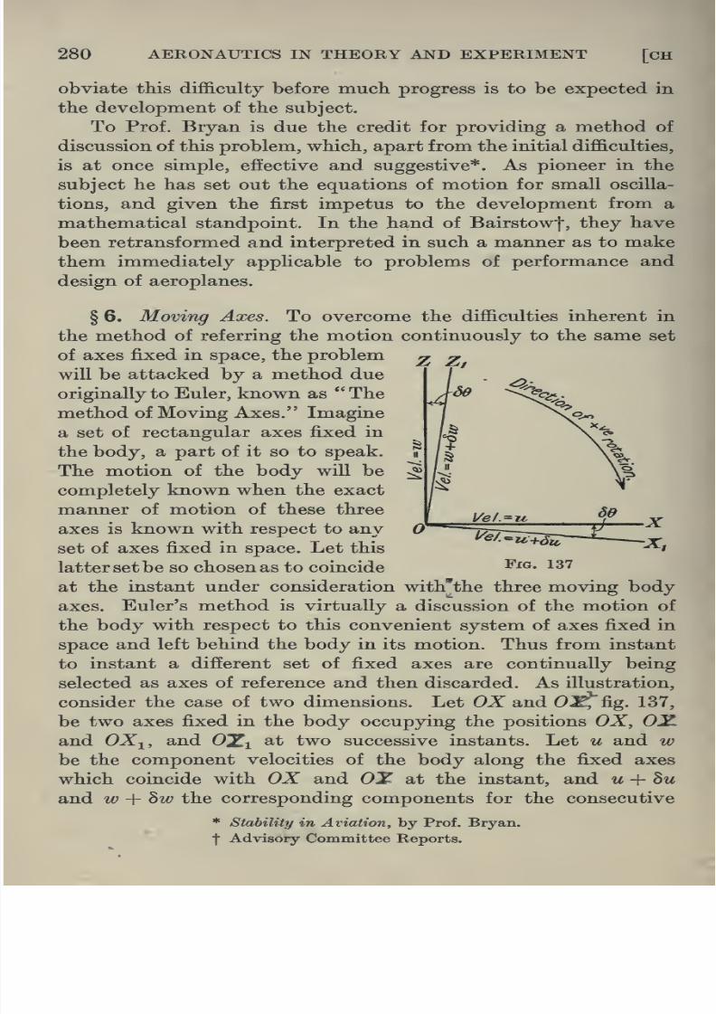
8/13/2019 Aeronautics in the 00 Cow Lu of t
http://slidepdf.com/reader/full/aeronautics-in-the-00-cow-lu-of-t 308/365
280 AERONAUTICS IN THEORY AND EXPERIMENT [CH
obviate this difficulty before much progress is to be expected in
the development of the subject.
To Prof. Bryan is due the credit for providing a method of
discussion of this problem, which, apart from the initial difficulties,
is at once simple, effective and suggestive*. As pioneer in the
subject he has set out the equations of motion for small oscilla-
tions, and given the first impetus to the development from a
mathematical standpoint. In the hand of Bairstow|, they have
been retransformed and interpreted in such a manner as to make
them immediately applicable to problems of performance and
design of aeroplanes.
§ 6. Moving Axes. To overcome the difficulties inherent in
the method of referring the motion continuously to the same set
of axes fixed in space, the problem ^ ^will be attacked by a method due
originally to Euler, known as The
method of Moving Axes. Imagine
a set of rectangular axes fixed in
the body, a part of it so to speak.
The motion of the body will be
completely known when the exact
manner of motion of these three
axes is known with respect to any
set of axes fixed in space. Let this
latter setbe so chosen as to coincide Fig. 137
at the instant under consideration with'the three moving body
axes. Euler's method is virtually a discussion of the motion of
the body with respect to this convenient system of axes fixed in
space and left behind the body in its motion. Thus from instant
to instant a different set of fixed axes are continually being
selected as axes of reference and then discarded. As illustration,
consider the case of two dimensions. Let OX and 0^, fig. 137,
be two axes fixed in the body occupying the positions OX, OXand OX^, and O^i at two successive instants. Let u and w

8/13/2019 Aeronautics in the 00 Cow Lu of t
http://slidepdf.com/reader/full/aeronautics-in-the-00-cow-lu-of-t 309/365
XIl] STABILITY—MATHEMATICAL THEORY 281
set of fixed axes. It is required, in the first place, to find an
expression for the acceleration of the body when in the position
determined by OX, OY. If W be the angle between the two sets
of fixed axes, then the components oi u-\-hu and w -{-hw along
the direction OX occurring, as they do, after an interval of time ht
are (u + hu) cosW and (w + hw) sin W. The increment in velocity
therefore along the fixed direction OX is
(u + hu) cos W + (w + hw) sin 86 — u
= 8u + w SO to the first order of small quantities.
Hence the acceleration of the body along the fixed direction OX,
when its moving axis OX happens to coincide with this fixed
5^ ^0 St dt dt
Similarly the acceleration along the fixed direction OY moment-
arily coincident with the corresponding axis in the body is
dw dd ,..
A-^s <'^>-
Without labouring the point it may be noted that du/dt, under
such a system, is thus not the acceleration but simply the limiting
ratio to the increment in time, of the velocity as measured along
the two sets of different axes.
§7. The more general case applicable to three dimensions
can be treated in precisely the same manner. If u, v and w be
the component velocities, defined as above, along the directions
OX,
OYand
OZrespectively, then
byresolving the new velocities
u + 8u, V + Sv, w + hw measured along the system of axes
coincident after an interval of time St, and proceeding as in the
simpler case discussed, the following equations are obtained,
positive rotation being Z to Y, Y to Z and Z to X.
du ' '
Acceleration in direction OX = X = -^— ^^s + '^^2 {^)>

8/13/2019 Aeronautics in the 00 Cow Lu of t
http://slidepdf.com/reader/full/aeronautics-in-the-00-cow-lu-of-t 310/365
282 AERONAUTICS IN THEORY AND EXPERIMENT [CH
where 6^, 62, 63 are the angular velocities of the body at the
instant under consideration about the three axes OX, OY, OZ
fixed in space and coincident with the corresponding movingaxes of the body. For a complete discussion of this method of
dynamical analysis the student is referred to Routh's Advanced
Rigid Dynamics, Chapter I.
The fact that different systems of new axes are continually
being adopted and discarded tends to destroy the utility of this
method for tracing out the flight path, but at the same time it
provides a simple means of obtaining a clear idea of the nature
of the motion at any given instant. It is proposed to apply
these equations to the case of an aeroplane in flight and to
determine whether, when subjected to certain disturbing forces,
its motion tends to converge to, or diverge from, that previously
existing.
Fig. 138
§ 8. Longitudinal Disturbances. The aeroplane, supposed
moving steadily in symmetrical straight line flight, is given a
small impulse in any direction in the plane of symmetry. This
instantaneously has the effect of changing the velocity of flight
and consequently also the resistance of the various parts by
corresponding small amounts. Since the motion and the dis-
turbance are both symmetrical, the problem can be treated in
two dimensions, i.e., in the plane of symmetry. The axes to

8/13/2019 Aeronautics in the 00 Cow Lu of t
http://slidepdf.com/reader/full/aeronautics-in-the-00-cow-lu-of-t 311/365
+
W^)= mgsmQ + mX-T (8),
XIlJ STABILITY—MATHEMATICAL THEORY 283
is supposed positive when its direction corresponds to an
increase of angle of attack. In such a case the forward velocity
of the machine to give rise to such positive forces must benegative. Positive pitching moment is measured in the same
direction as Q.
If mX and mZ be the components of the wind forces in the
directions OX and OZ at some time after the disturbance, then
the component forces producing accelerations along these direc-
tions are
OX mgsmQ + mX- T,
OZ — mg cos + mZ,
where T is the propeller thrust assumed acting along OX.
Using equations (3) and (4) for the motion of the centre of
gravity, the equations of motion become:
and m I -j-— U -j-j = — mg cos Q + mZ (9),
where U and W are the velocities in the space directions OXand OZ.
For the rotational motion about the centre of gravity we have
mK^Y^^mKKM (10),
where niK^ . M is the pitching moment due to the air forces,
neglecting gyroscopic effects of engine and propeller, and sup-
posing the propeller thrust passes through the centre of gravity.
The three equations given above are perfectly general and
therefore may be applied to the aeroplane immediately before,
and some time after, the disturbance. Let Uq, Wq, Xq, Zq, Tq,
00 and Mq be the values for the velocities, force coefficients, etc.,
during steady flight, and let these become Uq + u, Wq-\- w,
Xq + X, Zq + Z, Tq-\- T, 00 + ^ and M^-i- M after the impulse
where u, w, etc. are so small that second order terms may be
neglected. The following two sets of three equations are at
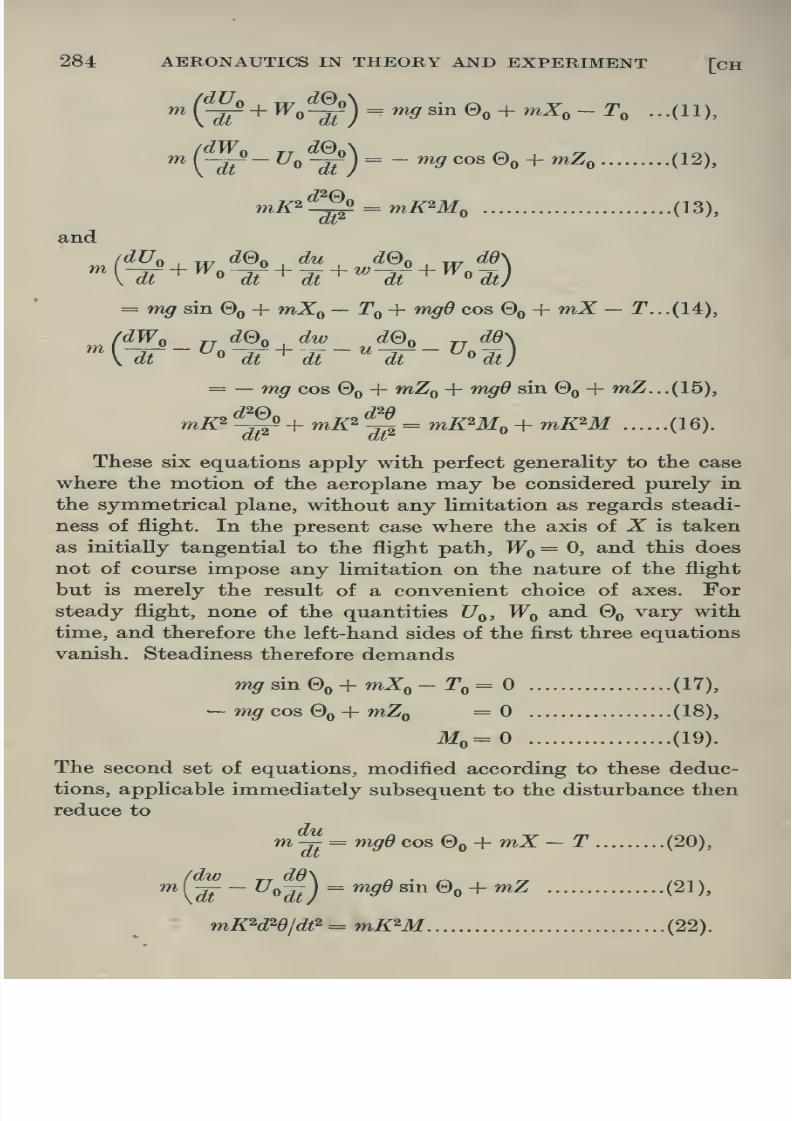
8/13/2019 Aeronautics in the 00 Cow Lu of t
http://slidepdf.com/reader/full/aeronautics-in-the-00-cow-lu-of-t 312/365
284 AERONAUTICS IN THEORY AND EXPERIMENT [cH
m
(^-Uo^^)=-n>g<^o^% + mZ, (12),\ at
mK^-j^ = mK'^MQ (13),
and
^K dt+^«
dt^'dt^'^'dr^^^Jt)= mg sin ©q + mX^ - jTq + w^r^ cos ©q + mZ - T. . .(14),
(dW, de, dw dSo jjdd\
'^VW~^''W^dt~''W~^Ut)
= — mg cos Sq + mZq + mgO sin @q + mZ... (15),
mir2'yfo+ mZ^II = mZWo + mZW (16).
These six equations apply with perfect generality to the case
where the motion of the aeroplane may be considered purely in
the symmetrical plane, without any limitation as regards steadi-
ness of flight. In the present case where the axis of X is taken
as initially tangential to the flight path, Wq = 0, and this does
not of course impose any limitation on the nature of the flight
but is merely the result of a convenient choice of axes. For
steady flight, none of the quantities JJq, Wq and Gq vary with
time, and therefore the left-hand sides of the first three equations
vanish. Steadiness therefore demands
w?^sin0o+ ttiXq- To= (17),
— w?^ cos 0Q + mZp =0 (18),
M„=0 (19).
The second set of equations, modified according to these deduc-
tions, applicable immediately subsequent to the disturbance then
reduce to
dij

8/13/2019 Aeronautics in the 00 Cow Lu of t
http://slidepdf.com/reader/full/aeronautics-in-the-00-cow-lu-of-t 313/365
XIl] STABILITY—MATHEMATICAL THEORY 285
§ 9. The latter three are the equations for small disturbances,
and upon them attention will be focused for the present. Each
of the quantities X, Z, T and M are actually determined by theshape of the machine and the small increments in velocities, etc.,
and as such must be considered as functions of the variables
u, w and 6. In effect, any variation in velocity, accompanied as it
would be by a change in angle of attack, gives rise to increments
in these air forces, etc. Accordingly since mX represents this
increase in force, using Taylor's expansion, it follows that
mZ = m(«g +«;U
+ eg) (23),
mZ = m(»||+»|| + ^g) (24),
r.Km^r.K^[u%+.% + e'^) (25),
• ^ = «l§ + -|J + ^i(26),
neglecting as before terms of higher order than the first. It must
be remarked that modifies the wind forces only in so far as it
affects u and w, and therefore cannot appear as an independent
variable. Each of the coefficients of u, w and 6 in the above four
equations has a special significance, and it is proposed to consider
these individually and interpret their bearing on the question at
issue. It must in the first place be emphasised that a vital dis-
tinction exists between the longitudinal force mX and the drag,
and between the normal force mZ and the lift. For this and later
purposes it is necessary to find the exact expression for mX and
mZ. Prior to the disturbance these forces respectively coincide
in direction, but after the appHcation of the impulse the one system
is inclined to the other by a small angle a representing the change
in angle of attack in the plane of symmetry. The relative wind,
U', has a component 11' sin a along the Z-axis. The velocity of the
machine itself along this axis is w and therefore V sin a = — w,
or since a is small ^ _ _ ^jjj' _ yjjjj^

8/13/2019 Aeronautics in the 00 Cow Lu of t
http://slidepdf.com/reader/full/aeronautics-in-the-00-cow-lu-of-t 314/365
286 AERONAUTICS IN THEORY AND EXPERIMENT [CH
where as before L and D are the lift and drag forces, and the
angle a is supposed small. Finally
mX=D- Lw/U (27),
mZ=DwlU + L (28).
In particular mXp = Dq and mZq = Lq .
These equations will now be utilised for the derivation of
the force derivatives.
§10. (i) ^;>xr or, as more commonly written, mX„
represents the rate of variation of the longitudinal force with
forward velocity alone, the other variables being supposed con-
stant. Experiment shows that the resisting forces are practically
.^PrlBLi^LfJk'itJ^^tf].
<^mm.
Fig. 139
proportional to the square of the velocity and for an aeroplane
independent of the acceleration, hence
X= KV^ where JJ is the velocity of the machine along the
X-axis as before and is essentially negative.
/. dXldU= 2KU=2U X X/U^=2X/U.
At the moment under discussion this velocity is Uq= — TJq
where JJq is the positive speed of the wind, and therefore Z„
becomes /aZ\ ^^Xq^2^ ^- _ 1_ ^

8/13/2019 Aeronautics in the 00 Cow Lu of t
http://slidepdf.com/reader/full/aeronautics-in-the-00-cow-lu-of-t 315/365
XIl] STABILITY—MATHEMATICAL THEORY 287
of the longitudinal force with the velocity W along the axis of Z,
the other quantities remaining constant, w decreases the angle
of attack by an amount wlU, i.e. a= — w/U, and therefore
this derivative represents the slope at a = of the normal force
curve, already referred to. Differentiating equation (27) it follows
that mXy, is likewise given by
1
Uo .^^ (^)oJ
f)X(iii) ^^ or as it will be written in future mX^, No
simple expression can be found for this quantity, which must
therefore depend for its determination on a special experiment.
Its significance however can easily be understood from a simple
consideration. Owing to the velocity of pitch the tail of the
machine moving downwards will meet the air at an increased
angle of attack, and is therefore equivalent to a variation in the
forces on the tail and therefore on the machine, the variation in
the X direction being measured by this quantity.
Following the same type of argument it will easily be seen
that
(IV) m^^:
7)7
(vi) m - - = mZg has a similar interpretation to (iii).
9M M(vii) m ^jj-= mMu = 2 ^^^ = for steady flight.
, .... dM ,^ dM 1
(vm)m^-^ = mM.= -^x^-,.
(ix) m —i- = mMq has a similar interpretation to (iii).
mZ^= 7 ^0 9 ^0 -2-^
'v--
mZ^ = slope of normal force curve with a at a ==
1
^^M

8/13/2019 Aeronautics in the 00 Cow Lu of t
http://slidepdf.com/reader/full/aeronautics-in-the-00-cow-lu-of-t 316/365
288 AERONAUTICS IN THEORY AND EXPERIMENT [CH
§11. Substituting in tlie three equations (20), (21), (22),
these approximate values X^, etc., for X, etc. derived in (23),
(24), (25) and (26), they reduce to
^^= {9COBeo)e+uX, + wX^ + f^X, ...(29 a),
^^^-Uof^ = {gsmeo)0 + uZ,+ wZ^ + ^^Z, (29 6),
S=-^^+S^^« (2^^)-
Writing the operator d/dt as D so that du/dt = DU, dW/dt^ = D^d,
etc., these equations take the symbolic form
(D -X^)u- X^w + (- XJ) - g cos Gq) 61 = ...(30 a),
- Z^u +{D-ZJ)w- [g sin Gq + (U^ + Z,)D]e=0 ...(30 6),
- M^w + (Z)2 - M,D) (9=0 ...(30 c).
A complete solution of these equations will determine u, w and 6
as functions of t. This will be obtained by eliminating any two
of these quantities between the above three equations by the
following simple step by step process. By multiplying (30 a)
by Zy, and operating on (30 b) by {D — XJ and subtracting, an
equation is obtained involving only w, 6 and their derivatives with
regard to time. Using this with equation (30 c) in a similar manner
a single relation involving 6 and its derivatives will be obtained.
This method evidently is equivalent to the process of eliminating
by the ordinary algebraic method the three quantities u, w and 6
between the three relations (30 a), (30 b) and (30 c), and no matter
which of these three is ultimately left, there will be the same
symbolic relation operating upon it, viz.,
D - X^, - X^, -X^D-gcosQQ
-Z,, D-Z^,-g sin &, - (U^ + Z,) D
0, -M^, D^-M,D
(u,w,e)=0...{31).

8/13/2019 Aeronautics in the 00 Cow Lu of t
http://slidepdf.com/reader/full/aeronautics-in-the-00-cow-lu-of-t 317/365
XIl] STABILITY—MATHEMATICAL THEORY 289
portional to e^' as in the case of the motion of the particle in the
tube already discussed, then
D^Kt _ Xe'^^ Z)V« = A2e^^ etc.,
and A may be substituted for D.
Hence from (31)
A-Z„, -Z,, -Z,A-5rcos0o = 0...(32).
-Z„ A-Z„ -5rsin0o-(C7o + Z,)A
Expanding the determinant by the ordinary method this takes
the form ^x* + jSA^ + CA^ + Z)A + ^= (33),
where -4=1,
5=-(M, + Z„ + ZJ,
0=1 Z,, To + Z,,
+M,Z„ +
Z)
0, M^, M,
- gM^ sin Sq,
E = gM^ Z„, cos 00
Z„, sin 00
§ 12. All the coefficients in this equation can be determined
for a given machine from a series of experiments on a model,
and an examination of the four roots of this biquadratic will
indicate whether or not the machine so constructed is stable.
It is important to investigate the significance of each root. The
differential equation (31) being of the fourth order will have as its
complete solution an expression of the form, say
e = A^e^^^ + A^e'^* + A^e^^* + A^e^^* (34),
where A^, A^, etc. are four constants depending for their values
on the initial conditions of displacement, and where e^'^\ e^^\
etc. are four independent particular solutions of (33). For

8/13/2019 Aeronautics in the 00 Cow Lu of t
http://slidepdf.com/reader/full/aeronautics-in-the-00-cow-lu-of-t 318/365
290 AERONAUTICS IN THEORY AND EXPERIMENT [CH
Keferring back to the general discussion on stability at the
beginning of this chapter, it is evident in the first place that the
conditions there demanded will be violated if any one of the four
roots be real and positive. On the other hand, if these four
quantities be real and negative, the motion will be stable, for 6
will then ultimately die out. There remains only to be discussed
the case of complex roots. If A^ = a + i^, then
gXxt = g(a+t^)< =^ e-f (cos pt + i sin ^0-
This term will consequently oscillate in value as time proceeds
with a period 2^/^ and amplitude e *. If a is positive, the magni-
tude of the oscillations increases indefinitely with time and the
motion, as far as this term is concerned, must be considered
unstable. If a is zero so that the root is purely imaginary, the
motion is simply harmonic and is unstable in the present re-
stricted sense. If a is negative, the amplitudes of vibrationcontinuously decrease and finally die out. These various types
of motion have already been represented in fig. 136. It follows
at once that an examination of the roots of
AX^+BX^ +CX^ + DX+E=0
from this point of view will determine whether the machine is
stable to exceedingly small longitudinal disturbances. Various
methods have been elaborated to facilitate such examination, and
these will be here shortly noted. These criteria also apply when
two or more roots of (33) are equal but the form of the solution is
not given by (34), as can easily be verified.
§13. (a) An initial test may be rapidly applied by the
following method. Writing
y=^AX^ + BX^ =-CX^-DX- E,
the required roots if real will be given by the intersection of the
two curves (I) and (II) in fig. 140, where
y=AX'^ + BX^

8/13/2019 Aeronautics in the 00 Cow Lu of t
http://slidepdf.com/reader/full/aeronautics-in-the-00-cow-lu-of-t 319/365
XIl] STABILITY—MATHEMATICAL THEORY 291
drawing, in the biquadratic, and by dividing out the other
quadratic factor is at once found and solved.
(6) The following approximation to the biquadratic in A is
found for most practical purposes to be sufficiently close, viz.
(A2 + BX + C) [A2 + (D/C - BEIC) A + EjC] = 0...(35),
taking A= \, and the roots follow at once by the solution of
each of the quadratic equations. It may be stated that this is
sufficiently accurate in general if
B is not greater than (7,
E is not greater than 0^/20,
and D is not greater than BG/20.
These conditions are usually satisfied by most machines.
CuriaeI^y^At+B)^
JI
Fig. 140
(c) It can be shown from the theory of equations, that the
biquadratic will furnish values of A corresponding to stable motion
provided A, B,C, D and E are all positive and Routh's discrimi-
nant, viz. BCD — AD^ — EB^, is positive. This is really the
condition that the roots of the equation shall all have their real
parts negative. For a complete discussion and proof of these

8/13/2019 Aeronautics in the 00 Cow Lu of t
http://slidepdf.com/reader/full/aeronautics-in-the-00-cow-lu-of-t 320/365
292 AERONAUTICS IN THEORY AND EXPERIMENT [CH
§ 14. Asymmetric Disturbances. The method that has been
developed for the treatment of longitudinal disturbances on the
equilibrium motion of the machine in symmetrical straight line
flight, may be applied with scarcely any modification to the
more general case where the disturbance, still small, is not
restricted to lie in the plane of symmetry. The axes of reference,
fixed as before in the body, will be the longitudinal axis of the
machine, OX, i.e. a line through the centre of gravity originally
parallel to the path of equilibrium flight, an axis
OZperpendicular
to this in the plane of symmetry, and one OY through the centre
Horizontal
'^
Fig. 141
of gravity perpendicular to this plane (fig. 141). The angle of roll
(/> corresponds to rotation about the original position of OZ, say
OZq, the angle of pitch d to rotation about OYq and the angle of
yaw j/f to rotation about OZ^ , all measured from the initial positions
before disturbance. These angles are all supposed small.
As a result of the disturbance, the machine ceases to occupy

8/13/2019 Aeronautics in the 00 Cow Lu of t
http://slidepdf.com/reader/full/aeronautics-in-the-00-cow-lu-of-t 321/365
XIl] STABILITY—MATHEMATICAL THEORY 293
new system of axes OX, OY, OZ. By simple resolution of angular
velocities it will be seen that the following relations exist between
these quantities, neglecting terms of the second order,
mdtoTcf> = p (36),
^=-q (37),
ijj^r (38).
Proceeding on the lines outlined in the earlier discussion, the
equations of motion of the centre of gravity of the machine in
the general case take the form
(^^~+WQ-VR^ = mX (39),n
(^J^+UR~WP] ^mY (40),
(^ + YF- UQ^ =-- mZ (41),
m
where U, V, and W are the linear velocities and P, Q, and R the
angular velocities about the new axes OX, OY, OZ. The equations
for the rotations about the centre of gravity are
^1 - RH^ + QH, = AL (42),
^ - PH^ + RH^ = BM (43),
^-^-QH, + PH,^CN (44),
where
Hi= angular momentum or moment of momentum of the
machine about the new axis OX,
Hi^PA-QF-RE,
H^=QB-RD-PF,
Hs= RC - PE - QD.
A, B and C are the moments of inertia about the axes OX, OY

8/13/2019 Aeronautics in the 00 Cow Lu of t
http://slidepdf.com/reader/full/aeronautics-in-the-00-cow-lu-of-t 322/365
294 AERONAUTICS IN THEORY AND EXPERIMENT [CH
applicable subsequent to the disturbance, neglecting second
order terms. Substituting Uq
+uioi U,v for F, w for W,
pfor P,
etc., since Vq, Wq, etc. are zero, then as before
m-T. = mX (45),
m(^+C/or) = mY (46),
m(^^-V,q)=mZ (47),
4-^1=^^ (^^)'
B^^ = BM (49),
Q^-E^= CN (50).
dt at
The forces mX, mY, mZ depend for their values on the com-
ponents of gravity and like AL, BM, CN upon the resisting forces
on the machine. The components of gravity along these three
directions are easily seen to be (fig. 141)
g sin 9o + g9 cos ©q in the X direction ...(51),
— gip sin 0Q — gcf) cos ©q i^ ^^^ Y direction . ..(52),
— g cos 0Q + gO sin Oq in the direction Z ...(53).
Expanding mX in a similar manner to that carried through in
equation (23), but including the propeller thrust and the gravity
term in the longitudinal force, we get
mX = (mg sin ©q + mZg — Tq) + m {6g cos ©q + ^^m+ vX^ + wX^ + pX^ + qX^ + rX;) . . (54),
and similar expressions for mY and mZ. The momental terms
on the right-hand side of equation (42) can likewise be thrown
into the following form, Lq, etc. being zero:
AL = A {uL^ + vL^ + wL^ + pL^ + qLg + rZ^)...(55),

8/13/2019 Aeronautics in the 00 Cow Lu of t
http://slidepdf.com/reader/full/aeronautics-in-the-00-cow-lu-of-t 323/365
XIl] STABILITY—MATHEMATICAL THEORY 295
A further simplification may be introduced by noting that certain
of the resistance derivatives must of necessity vanish. From
symmetry all derivatives of X, Z andM with respect to v, p, and r
and Y, L and N with respect to u, w and q are all zero. ilf„
moreover as before also vanishes. The equations (45) to (50)
for small oscillations under an asymmetric disturbance can now
be represented in the comparatively simple form
du
ItuX.
vY,
-nZ„
-vL.
-vN..
- wX^ - qXq - eg cos Q^ = 0,
-pYjj+ (pg cos e^ +r{Uo--Yr)^ i/'gr sin 00 = 0,
~-wZ^ -q{U,+Z^)-egBme, = 0,
-1--.Edr ^ ^
-wM^ +%-qM^ =0,
-1-^*' =»•
Kemembering that p = d(f>/dt, q = dO/dt and r = di/j/dt as already
derived, the above six differential equations suffice to determine
the six variables u, v, w, d,<f>,
xjj as functions of t. Proceeding as
in the case of longitudinal disturbances, this can most con-
veniently be done by supposing these quantities proportional to
e^*, and eliminating t. The following determinant is obtained
0,
0,
0,
0,
0,
-Xy^+Sr COS 00,
0,
- XXg - g cos Go
0,
-\{L\ + Z^)
- g sin 9q ,
X(C7o-r^)+S'sineo
0, -K^ 0, \^-\L^, 0, -^-x^.0, 0, -M^, 0, V-XJf,,
0, -N,, 0, -§x-xi^, 0, \^-\N^
This, as can easily be verified, reduces to the following two
determinants

8/13/2019 Aeronautics in the 00 Cow Lu of t
http://slidepdf.com/reader/full/aeronautics-in-the-00-cow-lu-of-t 324/365
296
and
AERONAUTICS IN THEORY AND EXPERIMENT [CH
A- 7, XYj,-\-gcosQQ, A(C/o- y^) + 5rsin0(
^X^~XN,,
XL,
X^-XN,
,(57).
§ 15. A remarkable conclusion can be immediately deduced.
The determinant (56) is identical with that derived in the dis-
cussion on longitudinal disturbances. Its terms do not involve
any of the quantities concerned with lateral motion. Determinant
(57) on the other hand is quite independent of any quantity that
arises from longitudinal disturbances. It follows at once that for
symmetrical straight line flight the problem of longitudinal stability
is quite unaffected by the question of whether the machine is
laterally stable or not.
§ 16. A discussion of this second determinant similar to that
carried through for the first will decide the question of lateral
stability. Expanding, we obtain
A^X^ + B^X^ + CiA3 + Z),A2 ^E^X+F^ = (58),
where
A,= 1-Ke'IK^'Kc',
Y Y
L^, Ljj, -
N N
1, Lr
-KeVKo', N,
— r.,
Ke'/Ka' i„,
1 iV., K,
0,
-1,
A = -
1I
Yr-U
Nr
Lp, Lj.
Y,-U + ^ cos 00I
X„ - Z^7Z^2I
Nr
N,,
+ g sin0oj
L,
1

8/13/2019 Aeronautics in the 00 Cow Lu of t
http://slidepdf.com/reader/full/aeronautics-in-the-00-cow-lu-of-t 325/365
XIl] STABILITY—MATHEMATICAL THEORY 297
One of the roots of the quintic equation in A is evidently zero,
and corresponds to the fact that the machine is directionally
neutral. The resulting quartic
^iA4+J5iA3+CiA2+Z)iA+^i = (59)
will determine the stability properly so called.
§ 17. The various tests for the roots that have been applied
in the case of longitudinal stability can similarly be used in
treating this quartic, the coefficients of which as before can
generally be determined by experiment. An approximate form
for equation (58) extremely useful in practice is
(60),
where E^ is not greater than 1/20 B^ or D^ , and B^D^ — C^^ is
not greater than 1/20 C^^, conditions which are usually satisfied
fairly closely. Frequently it is found that K^^ is negligible.
The interpretation of the foregoing results in terms of design
is reserved for the next chapter.
§ 18. General Remarks. Although the discussion has so far
been restricted to the stability of symmetrical straight line flight
the method can equally well be applied to the problem next in
importance and simplicity, steady circular and helical flight.
Under these circumstances the angular velocities about the axes
become finite in value and consequently, in equations (39 etc.),
there would now require to be substituted for P, Q and R,
Pq-^ Py Qo+ 9 and Rq + r.
At the same time the system of equations from which the deter-
minants are derived would be modified in form. This can be easily
obtained by similar resolution to that already carried through.

8/13/2019 Aeronautics in the 00 Cow Lu of t
http://slidepdf.com/reader/full/aeronautics-in-the-00-cow-lu-of-t 326/365
298 AERONAUTICS IN THEORY AND EXPERIMENT [CH XII
eighteen resistance derivatives which vanished previously for
symmetrical straight line flight have finite values difficult of
experimental determination, but all the derivatives now depend
for their values upon the angular velocities Pq, Q^, Rq in addition
to Uq, Vq, Wq. Even in the case of steady straight line flight if
terms be introduced involving the gyroscopic effect of the rotating
parts the solution is further complicated and results in an octic
in A.

8/13/2019 Aeronautics in the 00 Cow Lu of t
http://slidepdf.com/reader/full/aeronautics-in-the-00-cow-lu-of-t 327/365
CHAPTER XIII
STABILITY—EXPERIMENTAL
§ 1. The mathematical theory of the stability of an aeroplane
in steady straight line flight, outlined in the previous chapter,
indicates that the problem reduces itself to a discussion of the
two equations
AX' + BX^ + CA2 +DX -\-E =^0,
^lA* + BjX^ + CiA2 + D^X + ^1=0,
for longitudinal and lateral disturbances respectively, the co-
efficients being given by, since K^^ is nearly equal to zero,
A=l ^1 = 1
B=-{M^ +X^+ZJ B,= -{N^ + L^+Y,,)
C= Z^,Uo + Z^ + X„ ,X, + X,,X^ C,= Y^, Y^ + Y^,Y^-Uo + L^, L,
Jtf«,. Mq 0, Mq Z^, Z^ L„ Lp N„ N, Np,N,
D=-lX,,X^, X, -gM^ sine, D,= - Y„Y^,Y^-Uo + {L^. cos 00 + N^ sin 6
Z„,Z^. Uo + Z^ K. L^, Lr0, M^, M^ N,, N^, N,
1
E=gM^ Z„,cos 00 Ei =-gco3 Gol L^, L^\ +g sin Q,\L^,Lj,\.
Zu' sin 90 1^.,^. '*..*„l
§ 2. General Discussion of Derivatives. The coefficients are
functions of the various parts and settings of the machine, the
speed of flight and density of the air. For each flight path,
therefore, these quantities will assume a special value, and an
investigation into the stability or instability of a particular
machine would require to cover variations in these for the whole
flying range and height. It is conceivable at the outset that
although stability might exist at a particular height and speed,
it might not persist at a greater altitude and higher speed of

8/13/2019 Aeronautics in the 00 Cow Lu of t
http://slidepdf.com/reader/full/aeronautics-in-the-00-cow-lu-of-t 328/365
300 AERONAUTICS IN THEORY AND EXPERIMENT [CH
density diminishes to roughly two-thirds its ground value, it will
be seen that this variation might become of importance and would
therefore demand in such cases a re-estimation of the roots of the
biquadratic.
In general, however, for the same attitude, it is found that
even for such changes in density, the character of the stability
or otherwise is unaffected. The effect of change of speed on
the other hand, involving as it does a difference in the attitude
of the machine,is
of much deeper consequence, and an investiga-tion of the stability for various speeds within the flying range must
be carried through.
The resistance derivatives X^, etc., and the rotary derivatives
Mq, etc., are ultimately only to be determined accurately for a
particular machine by a special experiment, but the actual
carrying out of this experiment may be frequently avoided by
a calculation of these quantities, based on the magnitudes of the
parts most responsible in producing the effects associated with
each derivative. The degree to which such parts of the machine
as the elevators and tail plane, for example, affect the values of
these quantities, and the nature of the motion resulting from
the disturbance, can be clearly understood from the following
consideration which, at the same time, illustrates certain limita-
tions of the investigations of the previous chapter.
§ 3. Significance of Tail Plane and Elevators in Stability.
For a given machine it has already been shown that the elevator
setting determines the angle of attack in equilibrium and con-
sequently also the speed of straight line flight (cf. § 3, Chapter XI).
If, however, the restriction regarding equilibrium be removed it is
evident that to each elevator setting and angle of attack there will
correspond a pitching moment. A series of curves of the type
shown in fig. 142 can accordingly be constructed showing the
variation in pitching moment coefficient with angle of attack for
a series of settings jS^, jSg, etc. of the elevator, where the pitching
moment coefficient is defined as the pitching moment divided

8/13/2019 Aeronautics in the 00 Cow Lu of t
http://slidepdf.com/reader/full/aeronautics-in-the-00-cow-lu-of-t 329/365
XIIl] STABILITY—EXPERIMENTAL 301
equilibrium flight at the point a^ and that at ttg, where the slope
of the curve on crossing the horizontal axis is of opposite sign to
that of the former. At a^ a slight increase in angle of attack brings
into being a negative pitching moment producing a tendency for
the angle of attack to revert back to that at a^ . A slight decrease
in angle of attack produces a positive pitching moment, tending
again to throw the machine back to its original position. As
far as the present question is concerned, therefore, flight in the
position a^ is stable. At ^g, on the other hand, a similar considera-
sion indicates that an increase or decrease in the angle of attack
gives rise to a pitching moment in both cases throwing the machine
further from its position of equilibrium, a^ is therefore a position
Pj Attack.
Fig. 142
of instability. It would appear that for any of the elevator settings
jSj, jSg, etc., for any position in which the machine was placed,
the angle of attack would change continuously until it occupied
the positions a^, a^, etc., about which it would oscillate until it
finally settled. For an elevator setting of the type ^^, whose
pitching moment curve does not cross the horizontal axis until a^
is reached corresponding to an angle of attack below the no lift
position AB, the machine would continuously change its attitude
under the effect of this negative pitching moment, and passing

8/13/2019 Aeronautics in the 00 Cow Lu of t
http://slidepdf.com/reader/full/aeronautics-in-the-00-cow-lu-of-t 330/365
302 AERONAUTICS IN THEORY AND EXPERIMENT [cH
Suppose the pilot is in equilibrium flight at high speed with
an elevator setting jSq and angle of attack of course that at a^.
For disturbances less than a certain magnitude the flight is
stable. A larger disturbance, however, great enough to throw
the machine up to, or beyond, the position ag would drive it
finally to occupy the attitude of equilibrium a^'. In practice
this disturbance might be a gust of wind which thus suddenly
pitches the machine over to a large negative angle of attack,
and before there is any possibility of recovery on the part of the
pilot, there comes into play a downward wind force on the aero-
plane which together with the weight imparts an immediate
downward acceleration approximately equal to 2g. Unless
there be sufficient height available to afford opportunity for a
rapid alteration of the elevator setting, etc., disastrous conse-
quences would ensue.
The weakness of the mathematical analysis of stabiHty is in
this instance well brought out, for it appears from the discussion
of the preceding chapter that under these circumstances the
machine occupies a position of stability for small disturbances
whereas in actual fact for larger disturbances it is unstable.
§ 4. Estimation of Dimensions of Tail. For a clear under-
standing as to how such instability can be avoided by accurate
design of the parts responsible, it is of importance to analyse
exactly the manner in which the pitching moment curves of
fig. 142 arise. It is evident that two factors are of primary
importance in contributing towards the effect under discussion.
A reference to fig. 66, Chapter VI, indicates that, as the angle
of attack of the aerofoil increases, the centre of pressure moves
forward, and consequently a pitching moment about the centre
of gravity arises, the variation of whose coefficient with angle of
attack is given generally by fig. 143, curve A.
The only other part of the machine that produces a pitching
moment of any consequence is the tail. In value this moment
is approximately the product of the force upon the tail, and the

8/13/2019 Aeronautics in the 00 Cow Lu of t
http://slidepdf.com/reader/full/aeronautics-in-the-00-cow-lu-of-t 331/365
XIIl] STABILITY—EXPERIMENTAL 303
gravity and Ti the lift coefficient of the tail, or Uft on tail ^ pV^.
Since Ti is found to be practically proportional to the angle of
attack and is in fact usually — 0-025 (a — j8) where p is the angle
of no Uft and a the angle of attack of the tail, in degrees, this
may be written — 0-025^^ (a — j8). A change in elevator setting
will correspond to a change in jS only, while a can only vary with
the angle of attack of the machine. The discussion on downwash,
in fact, in Chapter VII indicates that a varies practically at a rate
equal to one-half that of the angle of attack of the main planes.
It is thus a simple matter to plot the pitching moment coefficient
due to the tail on the same base as that due to the main planes,
fig. 143. These give a series of parallel lines for various elevator
settings, the slope of which will be — 0-025^Z/2 (the straight line).
1
^ ^ -- '-'
^ ^'^^^^^i^^-c''^
^^^ ^>^-. Ang/e of
Fig. 143
By adding the ordinates of curve A and the latter algebraically,
at the same angle of attack the final pitching moment coefficient
curve, shown dotted, for the whole machine is obtained very
approximately.
The previous discussion and interpretation of this curve
indicated that in order to avoid instabihty no crossings of the
horizontal axis must occur at a positive slope, as for example
those at a^, etc., fig. 142, for some distance on each side of the
flying range of angle of attack. This will evidently be achieved,

8/13/2019 Aeronautics in the 00 Cow Lu of t
http://slidepdf.com/reader/full/aeronautics-in-the-00-cow-lu-of-t 332/365
304 AERONAUTICS IN THEORY AND EXPERIMENT [CH
only once. An approximate rule for setting a lower limit to the
leverage of the tail area follows at once. The main planes having
been selected according to the principles formulated in Chapters
V and VI, and their dimensions and the position of the centre of
gravity of the machine determined, a knowledge of the variation
of centre of pressure and lift and drag coefficients with angle of
attack will suffice for an estimation of the pitching moment
coefficient. If a be the maximum slope of this curve, then 0-0125^?
must be greater than o in order to avoid this type of instability.
§ 5. This illustration demonstrates the manner in which the
component parts of the machine operate together to produce or
avoid instability, and provides a moderately exact method for
determining the leverage of the tail required under certain
circumstances. For lateral effects a similar process might be
adopted, butin
this case evenwhen the calculations thus indicatedhave been carried through, it does not follow that if the aeroplane
be constructed to satisfy these demands it will be stable. Acertain amount of interference between the various parts might
and does take place, sufficient in certain cases to convert an
otherwise apparently stable machine into an unstable one.
Ultimately recourse must in all cases be had to an examination
of the two biquadratics for a final test, but it is important that
the region of investigation should be extended for some distance
beyond the normal flying range to allow in some measure for the
effect of finite disturbances.
§ 6. Experimental Determmation of Force and Rotary Deriva-
tives. Before the biquadratic can be properly built up, the values
of the coefficients must be derived from a knowledge of the force
derivatives and the rotaries. Generally it is possible to estimate
these roughly from the dimensions of the parts of the machine in
question, but more accurate and reliable information can only
be obtained by wind tunnel experiments on the complete model.
This would bring to bear on the flow past the various parts that

8/13/2019 Aeronautics in the 00 Cow Lu of t
http://slidepdf.com/reader/full/aeronautics-in-the-00-cow-lu-of-t 333/365
XIIl] STABILITY—EXPERIMENTAL 305
As has already been explained the various force derivatives
can be expressed in terms of the slopes of the lift, the drag, the
cross wind force, the pitching moment, the yawing moment and
the rolling moment curves, plotted against velocity, angle of
attack, and of yaw. The calculations must then be carried through
for stability at a particular angle of attack within the range of
these experimental determinations.
The longitudinal derivatives have already been treated in
some detail, and for convenience of estimation simple expres-sions for these and the corresponding laterals are tabulated
below.
Longitudinals Laterals
^-- WV' da) L„ =
J-gUo' dk' 1
2 _ 9^0 (<,.\gU,' a«„' 1
gU^' dmo 1
W ' da -
Kb''
where
£„= IJ}^ = total lift on complete machine,
Z)„= dJJ^ = total drag on complete machine,
No
pitching moment on complete machine,
total cross-wind force on complete machine,
rolling moment on complete machine,
n^ TJ^ = yawing moment on complete machine,
Kj^ = radius of gyration about OX,

8/13/2019 Aeronautics in the 00 Cow Lu of t
http://slidepdf.com/reader/full/aeronautics-in-the-00-cow-lu-of-t 334/365
306 AERONAUTICS IN THEORY AND EXPERIMENT [cH
when the controls are fixed for normal flying position at the angle
of attack under investigation.
Of the nine rotary derivatives M^, Nr, N^,, L^, Xg, L^,, Z^,
Yj,, Yr, the latter seven are exceptionally difficult of experi-
mental determination, and any such method that could be
devised would probably involve errors sufficiently great to vitiate
the results. Fortunately, however, these quantities are not of
sufficient importance, where they enter into the coefficients, to
demand more than a very approximate idea of their magnitude,
and it suffices to estimate this in general by calculation. The
method to be followed in these cases will be indicated shortly.
Both Mq and N^ on the other hand are very easily derived by a
simple experiment in the wind channel. In the case of Mg the
model is supported on its side by a vertical spindle, through the
centre of gravity of the machine, and attached to the channel
balance constrained to rotate about the axis of the spindle. Bymeans of a spring a slight angular displacement communicated
to the machine causes it to oscillate about the position of equili-
brium corresponding to the angle of attack. From a comparison
of the rate of damping with and without the wind, M^ is easily
calculated using the constants of the balance.
In the same way by supporting the model in the horizontal
position in the proper attitude, Nj. is determined.
To complete the discussion of the derivatives there remains
to indicate how those quantities, not conveniently obtained by
experiment, can be estimated from a knowledge of the dimensions
of the various parts of the machine. Incidentally there will be
shown the effect of variation in these dimensions upon the more
important derivatives.
§7. Effect of Various Parts. Illustration of approximate
calculation. Sufficient has already been said to make clear the
stabilising function of the tail. Its importance lies in the fact
that it tends to increase M^ which is proportional to the rate of
increase of the pitching moment with an increase in normal

8/13/2019 Aeronautics in the 00 Cow Lu of t
http://slidepdf.com/reader/full/aeronautics-in-the-00-cow-lu-of-t 335/365
XIIl] STABILITY—EXPERIMENTAL 307
There are two principal components of the machine that
govern and practically determine the lateral stability. These are
(a) the fin, and (6) the dihedral angle of the wings.
Fin. An elementary consideration will quickly separate out
the terms that are affected by the presence of the fin, and even
generally to what extent they are affected. A force upon the fin,
neglecting the drag, will modify the values of the force Y and of
the moments L and N. The change in Y being roughly propor-
tional to the area of the fin relative to the longitudinal cross-
section of the machine will be comparatively small, and is in fact
negligible. The variation in L, the moment about the longitudinal
axis due to the fin, has as leverage a comparatively small distance
and therefore may likewise be discarded in the face of more
important variations in L, such as that due to the wings them-
selves. There remains only to be considered the changes in the
moments about the normal axis. Of these N^ is of outstandingimportance.
N^, which comes into existence when the wind yaws relative
to the axis of the machine, is not easy to estimate. It is affected
by the body as well as the fin and rudder, the actual amount of
the body interference being determined by the proportions behind
and before the centre of gravity. It will be increased by an in-
crease in fin area, or by placing the fin further back from the
centre of gravity. The importance of this term will shortly be seen
when it will be shown that N^ tends to predominate in certain of
the coefficients of the biquadratic, determining their sign, and thus
indicating the effect on stabiUty. The chief terms affected, it will
be seen, are E^ and D^, the latter written very approximately as
D^^ - Y^ Lp, Lr -}-Uq L^, Lj, + gcosQ.L^.,, Lr + u. L,, L,
N„ Nr iV„, N,
Dihedral. In many respects the dihedral may be more easily
considered by supposing substituted an equivalent fin area
situated above the centre of gravity. The only term which is
to any extent affected is L^. As already indicated this term is

8/13/2019 Aeronautics in the 00 Cow Lu of t
http://slidepdf.com/reader/full/aeronautics-in-the-00-cow-lu-of-t 336/365
308 AERONAUTICS IN THEORY AND EXPERIMENT [cH
dihedral angle. Approximately, therefore, the moment is in-
creased by Q yI
I being the length of each wing, and this, for all practical purposes,
may be used for vL^
Summing up it appears that the effect of the fin will be most
apparent in the variation it causes in N^ while the dihedral on
the other hand makes itself evident by the changes it involves
in L^. It will be most convenient to trace the effects of these
two elements through their representative coefficients.
The effect of these derivatives can be seen immediately from
the fact that N^, if positive, tends to make D^ negative, and
therefore acts towards instability. If on the other hand this
derivative is large and negative, E^^ tends to become negative
and again acts towards instability. There exists between these
two extremes a range of values of N^ satisfying the conditions
for stability as far as both D^ and E^ are concerned.
From an examination of E^, it can be seen that N^ becomes
a factor when L^ is zero. It follows that, other things remaining
practically unchanged, the sign of Ej^ in this case would be
determined by N^ . If these quantities be positive, D^ , as already
seen, becomes negative and consequently indicates instability.
To obviate this difficulty, L^ must attain a positive value. Inter-
preted physically this demands the existence of a dihedral angle
on the wings.
The terms Xg, Zg, F^,, Y^. are for most machines small in
magnitude and, as long as they remain so, scarcely affect the
stability conditions. They will accordingly not be treated.
Lj,, Nj,, L,. on the other hand do attain some significance in the
equations, and their method of estimation can be briefly indicated.
The angular rotation p is equivalent as far as L is concerned to a
change in the angle of attack for each element of the wing. The
new normal force, or approximately lift, at each position on the
wing can thus be obtained and the moment mpLj^ derived by

8/13/2019 Aeronautics in the 00 Cow Lu of t
http://slidepdf.com/reader/full/aeronautics-in-the-00-cow-lu-of-t 337/365
XIIl] STABILITY—EXPERIMENTAL 309
element thus contributes towards the moment about the longitu-
dinal axis, and is estimated by summation.
The following typical values of the derivatives are given for
reference.
Ft.-sec. units.
m= wt. inlbs./^=40, KJ=^KB^ = 2b and 7^ = 35.
Longitudinal derivatives^ etc.
X„ = -0-14, Z„=-0-80, M,,=- 0,
X«,= 0-19, Z,= -2.89, M^ = 0-106,
Z,= ±0-5, Z,=:9-0, M,= -8-4.
ml derivatives.
r«=-o-25, i:,= 0-0332, i\^,= - -015,
r.= i, Z,= -8, iV,= - •57,
l^r=-3, X,= 2.6, N,^- 1-05*.
Physical Interpretation. Analysis of Types of
Oscillations Originated during Flight
§ 8. (i) Longitudinals. The biquadratic may be written in
the approximate form
[A2 + 5A + 0] [A2 + (DjC - BE/C^) A + ^/C] - 0,
and by considering each of these factors in turn it is possible to
correlate each part of the motion with the portion of the machine
concerned in producing it. Some of the terms in the coefficients
in this equation are found in practice to be so small that to a
sufficient degree of accuracy it is possible to write
+ M^{U^Xu-g^m%),
G =J
D = -M, Xu , x„

8/13/2019 Aeronautics in the 00 Cow Lu of t
http://slidepdf.com/reader/full/aeronautics-in-the-00-cow-lu-of-t 338/365
310 AERONAUTICS IN THEORY AND EXPERIMENT [CH
The solutions of the first factor equated to zero are
Both Mq and Z^ are negative and therefore instability could only
arise provided the term under the radical sign is numerically
greater than M^ + Z^ . This would involve M^ negative and
in absolute value MqZJU. Such a state of affairs can only arise
at such a point as ag, fig. 142, where My^ is negative. Assuming
this condition not satisfied, and it may be obviated by the
method described in § 4, it follows that the motion may consist
of two heavily damped subsidences. If the term under the radical
sign is negative, which is normally the case, the motion consists
of a damped oscillation of period
i7^|^^[iUM^ - {Mq - Z^)2] = 2 to 3 seconds usually.
The solutions of the second factor equated to zero are
2A == - (D/C - BE/C^) ± ViiD/C - BEjC^f - iE/C].
Generally the term D/C — BE/C^ is small compared with E/C,
and the motion is therefore a slightly damped oscillation of
approximate period 27tI-\/{EjC) = 15 to 25 seconds usually.
Since the quantity under the square root is practically always
negative the motion is oscillatory and instability could therefore
onlyarise
by the failure of the amplitude to decrease with time.Stability therefore demands that {DC — BE) must always be
positive. The type of oscillation here discussed is known as
Phugoid, and was first pointed out and explained by Lan-
chester.
§ 9. (ii) Laterals. The biquadratic equation in A corre-
sponding to lateral disturbances can be written in the approximateform
(A + EJD,) [A + {B/ - C,)IB,] [A^ + {CJB, - EJD,) A
+ B,DJ{B,^-C,)] = 0.
Consider the factor
X + (B,^-C,)IB,= 0.

8/13/2019 Aeronautics in the 00 Cow Lu of t
http://slidepdf.com/reader/full/aeronautics-in-the-00-cow-lu-of-t 339/365
XIIl] STABILITY—EXPERIMENTAL 311
The quadratic factor
A2 + (GJB, - EJD,) A + B,DJ{B,^ -C,) =
can with sufficient accuracy be re-written
A2 + OiA/5i + Ci2/5i2=0,
remembering that CJBj^ and E^jD^ have been supposed small,
and provided B^D^ is approximately equal to G^. It follows that
A=i[-C,/Bi±tV(3Ci75i^)].
This corresponds to a motion represented by
g-c.f/2B.sin((7j^V3/25i),
so that the oscillation is damped, G^ and B^ both normally being
positive, and the periodic time is 4:7t\/BJ3Ci, approximately
6 seconds.
Spin and Spiral Instability. By far the most important termin the biquadratic is A + EJD^ = 0. If E^^ and D^ be of opposite
sign, instability will arise. D^ can only become negative by N^
assuming a large positive value, as can be seen by consideration
of the value of that coefficient. This would mean that the yawing
moment due to side slip must be increased in the positive direc-
tion. This is equivalent to the existence of a small fin area. Such
a form of instability, tending to produce rotation of the machine
about a vertical axis through the centre of gravity, is usually
known as spin. Increase of the fin area appears to be the
obvious remedy. Such a course however would naturally tend
to diminish the rotation about a vertical axis through the centre
of gravity due to side slip, and would therefore cause N^, to assume
a comparatively large negative value. Reference to the expression
for El however indicates that this has the effect of making that
quantity negative, and therefore must contribute towards insta-
bility of a different type. How this arises physically can be seen
from a simple consideration. Suppose the machine is accidentally
banked. Initially the centre of gravity tends to move off along a
circular path, but the large fin area coming into operation swings

8/13/2019 Aeronautics in the 00 Cow Lu of t
http://slidepdf.com/reader/full/aeronautics-in-the-00-cow-lu-of-t 340/365
312 AERONAUTICS IN THEORY AND EXPERIMENT [CH XIII
flight path and so on, the radius of turn diminishing continuously.
During the above process the total lifting force has been con-
stantly decreasing, involving a continual drop in altitude, andthe motion ultimately developes into a rapid spiral nose dive;
hence the term usually applied to this type of instability, viz.
Spiral Instability.
§ 10. Following broadly the lines pursued in this and the
previous chapter, aeronautical investigators and constructors have
attained considerable success in the development of an aeroplane
possessing inherent stability. It must nevertheless not be supposed
that the best machine from this point of view is one possessing
the maximum degree of stability, but rather one possessing the
requisite measure to suit the convenience of the pilot. Too great
stability results in the aeroplane turning too readily into the
relative wind, and answering to every gust however slight. Such
machines moreover frequently do not respond easily to their own
controls.
Experience of machines in flight and an accurate study of
their performance have substantiated firmly the claim that the
modifications in design deduced from mathematical analysis of
stability to small disturbances are practically sufiicient to ensure
the production of an inherently stable machine. This cannot beregarded otherwise than in the light of a signal triumph for
mathematical science.

8/13/2019 Aeronautics in the 00 Cow Lu of t
http://slidepdf.com/reader/full/aeronautics-in-the-00-cow-lu-of-t 341/365
CHAPTER XIV
THE COMPLETE MACHINE
Conclusion
§1. In the preceding chapters an attempt has been made
to explain in some detail the methods and principles that must
be taken as guides in the selection of the various parts of a
machine. Generally an aeroplane is built to fulfil more particularly-
one function above others, but it does not necessarily follow that
such a machine will not at the same time be comparatively efficient
for other purposes. An aeroplane, for example, which has been
designed for high speed above other things may at the same time
rank as a fairly good climbing machine. It is outside the scope
of the present book to enter into details of design, but it is pro-
posed simply to indicate very generally where and how the
principles elaborated here are to be applied. The question centres
mainly around a selection of the aerofoil and the engine. In
Chapter V it has been shown how the choice of the aerofoil is to
be effected. A knowledge of the proposed landing speed and the
probable weight of the machine then determines the wing loading
and area. The body can be selected in accordance with the
principles explained in Chapter VII and the setting of the wings
with respect to it from the fact that, in the first place the drag
of the body should be a minimum in the required flying attitude,
and in the second that on landing as large an angle of incidence
of the wings to the relative wind should be obtained, the skid
touching the ground. For a high speed machine reduction in
resistance by diminution in the number of struts is of course a
desirable feature. Experience has shown that it is possible to
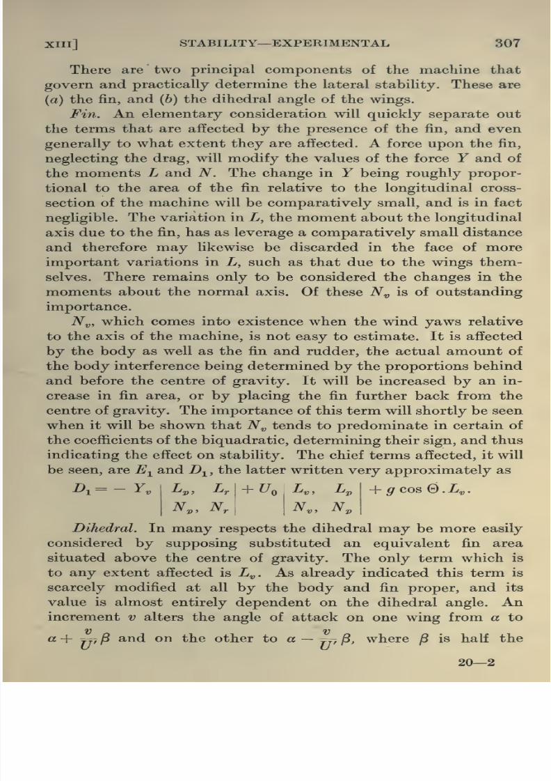
8/13/2019 Aeronautics in the 00 Cow Lu of t
http://slidepdf.com/reader/full/aeronautics-in-the-00-cow-lu-of-t 342/365
314 AERONAUTICS IN THEORY AND EXPERIMENT [cH
in head resistance. It may be recalled in passing that the calcu-
lations explained in Chapter VIII must be carried through for all
possible types of loading that the wings, in their manoeuvres,
may be called upon to withstand. The same estimation must
be made for the members of the body, tail, undercarriage, etc.
The dimensions of the tail and the remaining controls can be
determined by the methods explained in Chapter XIII, according
to the degree of stability required. A final detailed discussion
of stability ought to be carried through after the disposition of
the various weighty portions (engine, etc.) has been decided.
The propeller, whose diameter is fixed by the dimensions of the
machine, should be chosen in conformity with the explanations
in Chapter X, but it must be remembered that after all every
propeller is practically designed by intelligent modification of
a previously existing one of known performance.
§ 2. Until comparatively recent times the engine was by far
the most important element in the machine and the whole
construction centred round it. Now-a-days the internal com-
bustion engine has been so far developed that its importance
as the determining factor in the design of the aeroplane has
diminished. The designer now has at his disposal a comparatively
large number of engines of sufficiently low weight and low fuel
and oil consumption per horse-power. It is clear that the exact
value of these quantities will serve to limit considerably the
freedom of selection of the remaining portions of the machine.
The problem of weight in fact imposes very serious restrictions,
since hand in hand with the question of aerodynamic suitability
of partsgoes the problem
ofthe corresponding weights and
their
maintenance below certain limits.
§ 3. There is one further point in this connection that must
not be passed over. It is tacitly assumed in general that the
total resistance of the machine can be obtained by summing up
the resistances of the various parts tested separately, but it is

8/13/2019 Aeronautics in the 00 Cow Lu of t
http://slidepdf.com/reader/full/aeronautics-in-the-00-cow-lu-of-t 343/365
XIV] THE COMPLETE MACHINE 315
body and the planes, and the downwash from the wings upon the
tail plane. In the case of models where correction is made for
interference, experiment has shown that the resistance of the
complete model does not differ appreciably from the sum of the
resistances of its component parts. It does not follow of course
that this will apply with equal truth for a complete machine,
principally on account of the different degrees to which scale
effect modifies the resistance' of each part. Moreover there are so
many small projections, not usually finding their place in themodel, each one of which adds its quota to the complete resistance,
that the result cannot be estimated to any considerable degree of
precision. If the resistance of the complete machine under flying
conditions could be accurately measured, an empiric transforma-
tion factor might be determined to assist in the passage from model
to full scale. Such full scale tests are, however, extremely difficult
to carry through reliably.
§ 4. Aeroplane testing. To test an aeroplane scientifically,
and hence to determine its performance curve for the purpose
of effecting a comparison with other machines, it is necessary
that the test be conducted under standard conditions or that
the results be reduced to such. The forces on the wing, the
resistances of the parts of the machine and the performance of
the engine all depend directly on the density of the atmosphere
and therefore incidentally on the temperature and pressure. It
is clear that these vary continuously from time to time, and
that even two consecutive tests cannot be assumed conducted
under the same conditions. For purposes of standardisation,
consequently, the performance
—rate of climb, speed, etc.
—is
usually expressed as a value corrected to the standard density
at a stated height. On account of the variability of atmospheric
conditions as many tests as possible must be performed upon the
aeroplane in order to assure sufficient accuracy.
§ 5. There are three main series of measurements that must

8/13/2019 Aeronautics in the 00 Cow Lu of t
http://slidepdf.com/reader/full/aeronautics-in-the-00-cow-lu-of-t 344/365
316 AERONAUTICS IN THEORY AND EXPERIMENT [CH
and instruments have been devised for obtaining these with
greater or less accuracy.
With regard to the first two it will be possible to carry these
out provided efiicient means are to hand to measure air speed,
height, and for purposes of standardisation, density, pressure and
temperature. It has already been explained in Chapter II that
the pitot tube is used in ordinary wind channel work for the deter-
mination of wind speed. A similar device is normally employed
here. The instrument, the pressure at the nose of which is ^pv^,
is usually fitted to one of the struts and connected by a tube to a
drum, and by a measurement of the deflection of the membrane
the value of Ipv^ is obtained. Owing to the effect of interference
and disturbance in the atmosphere by the aeroplane itself, v is not
exactly the general speed of the machine, but this can be allowed
for by a previous test over a measured course at ground level.
It is clear that before v can be accurately calculated from this
pressure measurement, the value of p at the height at which the
experiment was conducted must be known, and this again
involves a knowledge of the pressure and temperature in that
position. The latter is of course determined by means of a ther-
mometer placed on the aeroplane well away from any heating
effect due to the engine. An aneroid barometer, whose function
is essentially to measure height differences by the variations in
pressure which are caused by such changes, unfortunately cannot
be relied upon to do this accurately on account of the variations
in temperature, etc. It is usually found more convenient to regard
it purely as a pressure instrument, so that each height indicated
on the scale corresponds to a definite pressure. From these two
measurements of temperature and pressure, the density follows
at once from p/p^ = j)TJpqT, T being the absolute temperature
and pQ , jpQ and Tq the values of these quantities at a fixed level
under standard conditions.
§ 6. When the aneroid is used for a measurement of height,
as already explained, it is subject to serious errors. In winter

8/13/2019 Aeronautics in the 00 Cow Lu of t
http://slidepdf.com/reader/full/aeronautics-in-the-00-cow-lu-of-t 345/365
XIV] THE COMPLETE MACHINE 317
require to be substituted. This depends initially upon the fact
that if ^1 and jp^ ^^ ^^^ pressures at any two points, and h^ and
^2 corresponding heights above the zero position, then
where T^ and Tg are the absolute temperatures at the points.
It is from this equation that the scale in heights is obtained from
the pressures for a given average temperature assumed by
manufacturers to be 10° C. It is unfortunately only in exceptionally
rare circumstances that the average temperature between the
ground and say 20,000 feet will reach as high as this, and con-
sequently to use the instrument as an accurate means of deter-
mining height, it is essential to correct by multiplying the height
indicated by T/283, where T is the average temperature absolute
over the range.
There is an alternative method of height and speed measure-
ment in common use frequently adopted as a check. Two camerae
obscurae are used, one pointing vertically upwards and the other
sloping at some particular angle. If they be situated at some
distance apart a considerable section of the sky can be projected
in both cases on a horizontal plane, and an aeroplane, operating
in this region, can be viewed from both points. A pilot in flight
can befollowed
bythe
twoobservers from point to point,
andby dotting his position on the charts every second, his ground
speed is determined. From his position on both charts, moreover,
his height is determined. This can be carried through to an
accuracy of 1 in 1000. To derive the air speed accurately it is
necessary to know the direction and speed of the wind at the
height of the test. This is achieved by arranging for the pilot
to fire off a puff of smoke and from a series of observations of its
motion the ground speed of the air is likewise obtained.
§7. There is one further determination necessary before
sufficient information is at hand to discuss the performance;
that is, the thrust and thrust horse-power. If the propeller has
been previously tested and if it can be assumed that during flight

8/13/2019 Aeronautics in the 00 Cow Lu of t
http://slidepdf.com/reader/full/aeronautics-in-the-00-cow-lu-of-t 346/365
318 AERONAUTICS IN THEORY AND EXPERIMENT [CH
however alter the thrust to a considerable extent in the working
region, and it would accordingly be more convenient and more
accurate, if possible, to obtain the value of this quantity, in such
an event, from the efficiency-slip curve. For this purpose the
engine is initially tested for horse-power output and revolutions
under conditions approximating as far as possible to those of
actual flight. Knowing the efficiency of the propeller from the
curve the thrust horse-power can easily be derived.
§ 8. The performance curves proper may be constructedfrom these data and analysed by the methods adopted in pre-
ceding Chapters (V, X and XI), with special reference to such
critical points as maximum rate of climb, maximum speed of
horizontal flight and maximum height possible or ceiling, but
for these, special tests are usually conducted. Associated with
each of these, instruments have been devised to facilitate the
measurements. In particular a simple and effective apparatus
is used for determining the best climbing speed of a new machine
or the maximum rate of climb. It consists of a thermos flask
connected to a liquid pressure gauge of small bore measuring the
difference of pressure between the inside and the outside of the
flask, and is at the same time open to the air by a capillary tube.
During climb, since the atmospheric pressure in general is con-
tinually diminishing, air will commence to leak from the flask
outwards since the pressure in the latter is greater. This will
continue until the leaking takes place at such a speed that the
rate of change of pressure inside the flask is equal to the rate of
change of atmospheric pressure. When the maximum rate of
climb is attained, therefore, the pressure difference between the
inside of the flask and the external atmosphere will be a maximum,and this will be indicated by a maximum height of liquid in the
pressure gauge.
It is clear that this instrument in reality measures the rate
of change of pressure as the machine climbs and consequently,
if the exact relation on the particular day when the instrument
is used be known, between height and pressure in the region of
8/13/2019 Aeronautics in the 00 Cow Lu of t
http://slidepdf.com/reader/full/aeronautics-in-the-00-cow-lu-of-t 347/365
xiv] THE COMPLETE MACHINE 319
Aeroplane Data.
Consumptiontrials
At R.P.M.
normal
At R.P.M.
economical
Total weight of aeroplane at start . . 2295 W 2376 (2)
Altitude during trial ... 8000 ft. 8000 ft.
Duration of trial excluding descent 1 hr. 13 min. 1 hr. 18 min.
Time occupied in reaching alt. of trial — 17 min.
Petrol at beginning of trial 57 galls. 57 gaUs.
Oil „ „ „ 7 „ 7 „Consumption of petrol per hour 11-5,, 10 „
„ oil 2 „ H„Loss of cooling water —Engine R.P.M. during trial •{
1350 on ground
1770 at 8000'
1440 on ground
1540 at 8000'
True air speed 79 64
Air speed indicator used Clift Clift
Ground speed „ — —„ „ method of measurement — —
Height of barometer 29-35 29-4
Temperature on ground 62° F. 57° F.
Speed trials
Total weight of aeroplane at start
Altitude during trial
Max. speed over ground, corrected for still air
Min. „
Engine r.p.m. at max. speed
min. „
Height of barometer
Temperature
2576 (3)
10 ft.
101-5 M.p.H.
60 approx.
1975 1
1200-1275
55° F.
2576 (3)
8000 ft.
Mean speed =94 M.p.H. ap.
prox. at 1830
R.P.M.
Climbing trials
Height
over
ground
ft.
TimeRate of
climb (ft.
per min.)
Engine
R.P.M.
Air speed
by indi-
cator
Total weight of aeroplane
at start ...
Consumption, petrol, galls.
oil
Duration of climb
Barometric height
Temperature on ground ...
Height of ground above sea
level
2319 (')
2
60 min.
29-3
60° F
1000
2000
3000
4000
5000
6000
7000
8000
r 30
3' 30
5' 50
8' 30
ir 0
13' 30
17' 0
21' 30
1500
1500
1500
1480
60
59
56
53

8/13/2019 Aeronautics in the 00 Cow Lu of t
http://slidepdf.com/reader/full/aeronautics-in-the-00-cow-lu-of-t 348/365
320 AERONAUTICS IN THEORY AND EXPERIMENT [CH XIV
a spirit level. In order to attain maximum speed in horizontal
flight the pilot must fly with his engine all out, and the
elevators adjusted so as to give no reading on the manometer.The foregoing table of data obtained from an actual test may
be taken as a typical specimen.
§ 9. On account of the extreme accuracy with which model
experimental tests may be conducted it is clear that practically
the only error that may arise is that inherent in the fact that
the research is conducted upon models, viz. scale effect. To
remedy this deficiency the tests conducted on full scale machines
have been extended with a view to supplying information on
this point. Although, as already indicated in the preceding
pages, tests on the complete aeroplane supply extremely valuable
information, inaccuracies non-existent in wind channel tests enter
and unless adequate precautions are adopted may tend to vitiate
the results. This will become clear when it is remembered that if
an upward current of as little as one foot per second be unwittingly
encountered the error involved in the estimation of wind drag
may amount to as much as 15 per cent. Such an experimental
error can clearly only be eliminated by an extremely large series
of tests. Apart from the possible deficiency in respect of scale effect,
model experimental work occupies a unique place on account of
the control that may be obtained over the experimental conditions
and the invaluable information it provides in comparative design.

8/13/2019 Aeronautics in the 00 Cow Lu of t
http://slidepdf.com/reader/full/aeronautics-in-the-00-cow-lu-of-t 349/365
GLOSSARY OF AERONAUTICAL TERMS
BASED ON THE LIST PRODUCED BY THETECHNICAL TERMS COMMITTEE OF THEAERONAUTICAL SOCIETY OF GREAT BRITAIN
Aerofoil. A structure, analogous to the wing or tail of a bird, designed
to obtain a reaction from the air approximately at right angles
to the direction of its motion.
Aileron. See Balancing Flaps.
Airscrew. Used as a generic term to include both a propeller and a
tractor screw. See Screw.
Alighting Carriage. See Carriage.
Aneroid. Instrument used k)r estimating height.
Angle, Dihedral. In geometry the angle between two planes. The
wings of an aeroplane are said to be at a dihedral angle when both
right and left wings are upwardly or downwardly inclined to a
horizontal transverse line. The angle is measured by the inclina-
tion of each wing to the horizontal. If the inclination is upward
the angle is said to be positive, if downward, negative.
Angle, Gliding. The angle between the horizontal and the path along
which an aeroplane in ordinary flying attitude, but not under
engine power, descends in still air.
Angle of Incidence or Angle of Attack. The angle a wing makes with
the direction of its motion relative to the air. The angle is
usually measured between the chord of the wing and the direction
of motion, when parallel to the plane of symmetry of the machine.
Attitude. An aeroplane's or wing's position relative to the direction
of motion through the air.
Back, To. Of the wind, to change direction counter-sunwise (counter-
clockwise).
Balancing Flaps. Aerofoils used for causing an aeroplane to roll about
its longitudinal axis for the purpose of balancing.

8/13/2019 Aeronautics in the 00 Cow Lu of t
http://slidepdf.com/reader/full/aeronautics-in-the-00-cow-lu-of-t 350/365
322 AERONAUTICS IN THEORY AND EXPERIMENT
Body. Of an aeroplane—that part which usually contains the engine,
crew, tanks, etc., and to which the wings, carriage and other
organs are attached.
Bracing. A system of stmts and ties to transfer a force from one
point to another.
Bulkhead, (a) In wing structure, a section through a gap strut
parallel to the plane of symmetry.
(b) In a fuselage constructed of girders of the N type, a
section through the struts perpendicular to the axis of the
machine.
Cabaue. A French word to denote the mast structure projecting
above the body, to which the top load wires of a monoplane are
attached.
Cabre. Tail down.
Camber (of a wing section). The convexity of a wing section. The
camber is usually measured (as a fraction of the chord) by the
maximum height above the chord.
Cant. To tilt ; to take any inclined position.
Carriage. That part of the aircraft beneath the body intended for
its support, on land or water, and to absorb the shock of
alighting.
Ceiling. Maximum height attainable by an aeroplane or airship.
Chassis. See Carriage.
Chord. The straight line joining the leading and trailing edges of
an aerofoil and parallel to the plane of symmetry.
Clinometer. See Inclinometer.
Control Lever. On an aeroplane, a lever by means of which the
principal controls are worked. It usually controls pitching and
rolling.
Cross-section. Of an aerofoil. The section cut by a fore and aft
plane normal to the surface (commonly the under-surface).
Cross-wind Force. Component of resultant wind force perpendicular
to the lift and drag.
Decalage. The difference in angle of incidence between the two
planes of a biplane.
Dihedral Angle. See under Angle.

8/13/2019 Aeronautics in the 00 Cow Lu of t
http://slidepdf.com/reader/full/aeronautics-in-the-00-cow-lu-of-t 351/365
GLOSSARY OF AERONAUTICAL TERMS 323
Drift The distance drifted. The speed of drifting. The word drift
having a well-accepted nautical significance should be avoided
as far as possible in the sense of head resistance or drag.
Drift, To. To be carried by a current of air or water ; to make leeway.
Elevator. An aerofoil set in a more or less horizontal plane and hinged
on an athwartships or transverse line. It is used for controlling
the angle of incidence of the aeroplane.
Entering Edge. See Leading Edge.
Fairing. Apiece
addedto any structure to reduce its head resistance
or drag.
Fins. Subsidiary aerofoils set parallel to the normal direction of
motion of an aircraft.
Flaps, Balancing. See under Balancing Flaps.
Flaps, Wing. See under Balancing Flaps.
Fuselage. A covered-in tapering structure connecting the tail system
to the remainder of the machine(cf. Outrigger ).
Oap. The distance between the upper and lower wings of a biplane.
For specific purposes the points between which it is measured
should be indicated.
Glide, To. To fly, usually on a descending path, when the aircraft
is not under engine power.
Gliding Angle. See under Angle.
Incidence, Angle of. See under Angle.
Inclinometer. An instrument for measuring angle of slope of an
aircraft, referred to the horizontal.
Lateral Force. Component of resultant force perpendicular to plane
of symmetry.
Leading Edge. Of a wing—the forward edge.
Leeward. Away from the wind.
Leeway. Lateral drift to leeward.
Lift. The force exerted by the air on an aerofoil in a direction
perpendicular to the motion, and in the plane of symmetry.
Usually upwards in ordinary flight.
Longeron. See Longitudinals.

8/13/2019 Aeronautics in the 00 Cow Lu of t
http://slidepdf.com/reader/full/aeronautics-in-the-00-cow-lu-of-t 352/365
324 AERONAUTICS IN THEORY AND EXPERIMENT
Normal Force. Component of resultant force perpendicular to axis
of machine and parallel to the plane of symmetry.
Outrigger. An open framework used for supporting the tail system.
Pancake, To. To descend steeply with the wings at a very large
angle of incidence, like a parachute. Contrast Dive.
Phugoid. A type of fore and aft oscillation as the result of a dis-
turbance.
Pitch, To. To plunge in the fore and aft direction (nose up or down).
Contrast this with Roll.
Pitot Tube. A tube with open end facing wind which, combined
with a static pressure or suction tube, is used in conjunction
with a gauge to measure fluid pressures and velocities.
Pressure Tube, Static. A tube (usually with holes in its side past
which the fluid flows) so designed that the pressure inside it
equals the pressure exerted by the fluid on any body at rest in
the fluid. Used as part of a pressure head.
Propeller. An airscrew behind the main supporting surfaces. Com-
pare Tractor.
Pylon. A mast or post.
Rib. Of a wing, a light fore and aft member which carries the fabric
for the purpose of giving the desired cross-section to the wing.
Rib, Compression. A rib designed to act as a strut between the front
and rear spars of a wing.
Roll, To. To turn about the fore and aft axis.
Rudder. A subsidiary aerofoil (in an aeroplane more or less per-
pendicular to the main supporting surfaces) by means of which
the aircraft is turned to right or left.
Rudder Bar. The foot-bar, by means of which the rudder of an
aeroplane is worked.
Rudder Post. The main post of a rudder.
Screw, Air. An aerofoil so shaped that its rotation about an axis
produces a force along that axis for driving an aircraft. (See
Propeller and Tractor. )
Side Drift. See Drift.
Side Slip, To. In an aircraft, to move more or less broadside on

8/13/2019 Aeronautics in the 00 Cow Lu of t
http://slidepdf.com/reader/full/aeronautics-in-the-00-cow-lu-of-t 353/365
GLOSSARY OF AERONAUTICAL TERMS 325
Spar. A long piece of timber or other material. In a wing, either of
the beams which run transverse to the aircraft, and transfer the
lift from the ribs to the frame and bracing.
Stagger. Of wings. When the wings of a biplane are set with the
upper one slightly ahead of or abaft of the other, they are said
to be staggered. The stagger is measured by the angle made by
the lino joining the leading edges with the normal to the fore and
aft axis of the aeroplane, or sometimes normal to the chord. It
is convenient to call the stagger positive if the upper wing is
ahead of the lower.
Stalling Angle. Angle of attack of the wings at the minimum speed
of flight.
Static Pressure Tube. See under Pressure.
Statoscope. An instrument to detect the existence of a small rate
of ascent or descent.
Strainer. An appliance bearing a suitable mesh for straining impurities
from petrol and other fluids.
Stream line. A line traced out in the fluid indicating the direction
of motion of the fluid at that instant.
Strut. A structural member intended to resist compression in the
direction of its length.
Strut, Gap or Interplane. The vertical struts connecting the wings
of a multiplane.
Tail. The after-part of an aircraft, usually carrying certain controllingorgans.
Tie. A structural member intended to resist tension.
Top Load Wires. See under Wires.
Top Surface Camber. See under Camber.
Top Warp Wires. See under Wires.
Tractor. An airscrew mounted in front of the main supporting
surfaces.
Tractor Machine. An aeroplane with airscrew mounted in front of
the main supporting surfaces.
Trailing Edge of a Wing. The after edge.
Triplane. A machine with three lifting surfaces one above the other.
Turnbuckle. A form of wire tightener.

8/13/2019 Aeronautics in the 00 Cow Lu of t
http://slidepdf.com/reader/full/aeronautics-in-the-00-cow-lu-of-t 354/365
326 AERONAUTICS IN THEORY AND EXPERIMENT
Warp, To. Of a wing, to bend so that the outer end of the back
spar moves up or down. It is convenient to call the warp positive
when the movement is downwards.
Wing Flaps. See Balancing Flaps.
Wings. The main supporting organs of an aeroplane.
Wires, Anti-lift. Wires, the principal function of which is to take the
vertical load due to the weight when the machine is not in flight.
Wires, Drag. Wires, the principal function of which is to transfer
the drag of the wings to the body or other part of the aeroplane
structure. Wires intended mainly to resist forces in the opposite
direction to the drag are sometimes called anti-drag wires.
Wires, Drift. See Wires, Drag.
Wires, Incidence. The cross-bracing wires between the wings parallel
to the plane of symmetry.
Wires, Lift. Wires, the principal function of which is to transfer
the lift of the wings to the body or other part of the aeroplane
structure.
Wires, Top Load. Wires intended mainly to resist forces in the
opposite direction to the lift.
Wires, Top Warp. Top load wires connected to the back spar and
passing from wing to wing to allow the wings to warp.
Wires, Warp. Lift wires connected to the back spar and controlled
so as to move its outer end down for the purpose of warping the
wing.
Wire-strainer. See Turnbuckle.
Yaw, To. An aircraft is said to yaw when its fore and aft axis turns
to right or left out of the line of flight. The angle of yaw is the
angle between the fore and aft axis of the aircraft and the
instantaneous line of flight.
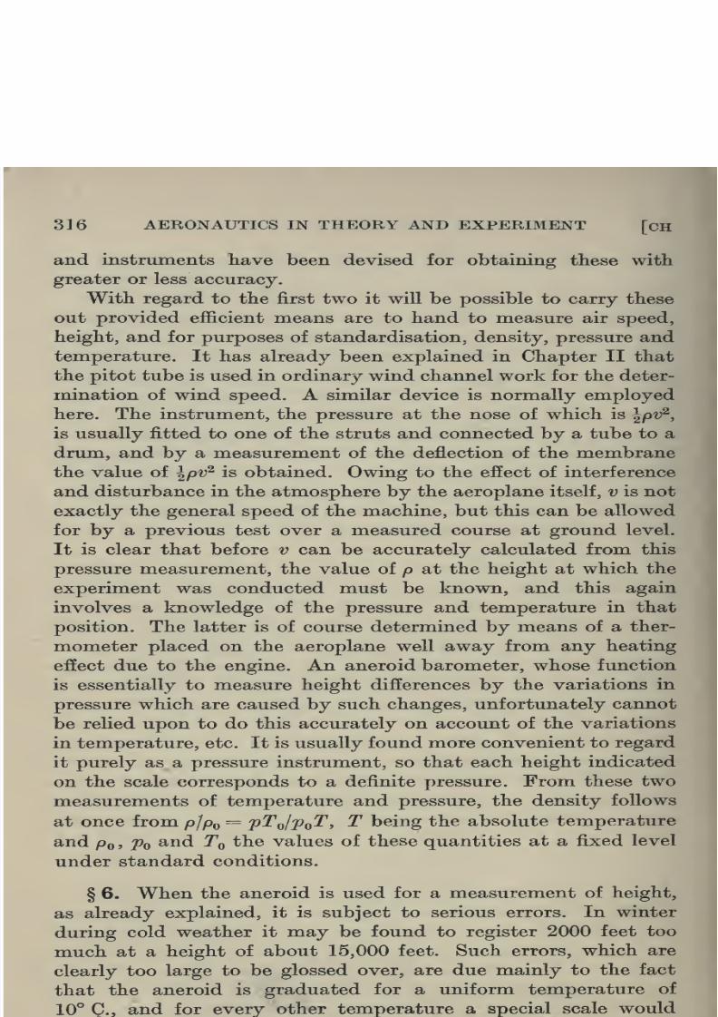
8/13/2019 Aeronautics in the 00 Cow Lu of t
http://slidepdf.com/reader/full/aeronautics-in-the-00-cow-lu-of-t 355/365

8/13/2019 Aeronautics in the 00 Cow Lu of t
http://slidepdf.com/reader/full/aeronautics-in-the-00-cow-lu-of-t 356/365

8/13/2019 Aeronautics in the 00 Cow Lu of t
http://slidepdf.com/reader/full/aeronautics-in-the-00-cow-lu-of-t 357/365
INDEX
Absorber -shock, 5, 272
Acceleration—resistance due to, 31
Accuracy of models, 12
Actuator, 239
Actuator disc, 239Aerofoil, 98 et seq.
„ combination, 128
„ —pressure distribution
round, 120
„ section, 113
R.A.F. (), 99
Aeroplane data, 319
„ testing, 315
„ wings, 21, 147
Ailerons see wing flaps
Air—elasticity of, 30
Airflow near propeller, 238, etc.
Airscrew, 222
„ blade element theory, 233,
etc.
Airspeed indicator, 28
Altitude—effect of, 261
Analysis of stability, 278, 27^
Anemometer (Pitot), 28
Aneroid, 316
Angle of attack, 93
„ of bank, 266, 269
„ of climb (best), 107
„ —critical, 25, 100
„ —dihedral, 154, 307
„ —gliding, 258, 261
„ of pitch, 149
„ of roll, 149
„ of stagger, 129
„ of yaw, 149
„ of zero lift, 99Anticyclonic weather, 32
Aspect ratio, 98, 118
Asymmetric disturbances, 292
„ straight line flight, 259
Atmospheric conditions, 32
Attack—angle of, 93
Available h.p., 106, 230, 261
Axes—moving, 280
,, of reference, 149, 282, 292
Balancing limitations, 150
Bank, 152, 260
„ —angle of, 266, 269
Banking, 266, 269
Beam theory, 166Bending moment—effect of thrust on,
173
Biplane, 128, etc.
„ correction from monoplane,
135
„ wings—distribution of load
on, 159
Biquadratic for longitudinal stability,
289
Blade—breadth of airscrew, 231
„ —design of airscrew, 251
„ element theory for airscrews,
233
„ of a propeller, 224
„ —vibration of airscrew, 251
Body, 4, 143, 144
Boss of airscrew, 224
Bracing wires, 4
Breadth of propeller blade, 231
Bryan—Prof., 280
Buckling of struts, 195 et seq.
Bullet—waves due to motion of, 31
Burble point, 25
Calibration of wind channel, 30
Camber, 24, 113
Cambered plane—discontinuous flow
past, 62
Centre of gravity, 127
„ of pressure, 118, 124, 128, 158
Channel balance, 9, 11
„ —water, 25
„ —wind, 8, 137, 316
Chassis, 5
Chattock gauge, 29
Circular cylinder—perfect fluid flow
past, 45
flight, 263, 266, 267, 268
—constant radii curves,
268

8/13/2019 Aeronautics in the 00 Cow Lu of t
http://slidepdf.com/reader/full/aeronautics-in-the-00-cow-lu-of-t 358/365
328 INDEX
Circulation, 42
Climb—rate of, 105, 107
Climbing machines, 104, 114
Coefficient of kinetic viscosity, 15, 74Coefficients—drag and lift, 92
„ —non-dimensional, 228
„ —thrusts and torque, 227,
250
Compressibility, 16
Conditions of crippling a supported
system, 219, etc.
Controlling surfaces, 148
Controls, 142
Correction for gap/chord ratio, 132,133
„ „ monoplane to biplane
anatriplane,135, 136
„ „ rounded wing tips, 120
„ „ scale effect, 141
Crippling of struts, 195, etc.
„ of supported system, 219,
etc.
Critical angle, 25, 100
„ behaviour of structures, 195„ velocity, 20, 23
Currents—vertical, 6
Curves—airscrew torque, thrust, ef-
ficiency, 225, 226, 229, 230
„ —performance, 106, 260, 262,
266, 267, 2o8, 271, 318
„ —pitching moments, 301, 303
„ —thrust grading, 252
„ —torque h.p., 231
Cyclones, 33
Data of performance, 319
Definition of stability in relation to
disturbance, 278
Deflection of aeroplane structures,
162, 163
Density—table of, 33
Derivatives—resistance, 286, 287, 305
—stabUity, 286, 287. 305
Design of a strut, 207
„ of propeller blade, 251
Determinantal equation of stability,
289, 296
Determination of derivatives for
stability, 304
Dihedral angle, 154, 307
Dimensional theory, 85 et seq.
„ „ for structures,
210, etc.
Dimensions of tail plane, 302
Distribution of pressure, 120
„ „ „ over propeller
blade, 231
„ of stress, 156Disturbances—asymmetric, 292
„ —longitudinal, 282
Dive—vertical, 258
Down wash, 153, 303
Drag coefficient, 92
Dynamical similarity, 90, 91
Economy in weight, 147
Eddying, 19 et seq.
Edge—leading and trailing, 122Effect of altitude, 261
„ of propeller slip stream on body,
146
„ of scale, 87, 136, 141, Ch. iv,
Ch. VI
„ of scale on propellers, 246
„ of tail on stability, 301
Efficiency of machine, 108
„ of propeller, 228
Elasticity ofair,
30Element theory for airscrews, 233
Elevator balanciug, 152
Elevators, 143, 151
Elevator setting, 259
Elevators in stability, 300
Elliptic cylinder—flow past, 52
End thrust effect on bending moment,
173
Energy in fluid—dissipation of, 19, 79
Engine, 102, 104, 108, 110, 313
„ revolutions, 230
Equation of longitudinal stability, 288
„ of pressure, 38, 41, 44, 53
„ of stability in general, 295
,, of viscous fluid, 82
Equipotential lines, 44
Equivalent fins, 153
Estimation of dimensions of tail, 302
Euler's critical length, 216 etc.
„ load, 209, 219
Eabric, 4
Failure of wing spars, 222
Fin effect of propeller, 154
„ „ on stability, 307
Fineness ratio, 21
Fins, 153, 307
Flaps—wing, 3, 152
Flexural rigiditv of struts—variable,
202

8/13/2019 Aeronautics in the 00 Cow Lu of t
http://slidepdf.com/reader/full/aeronautics-in-the-00-cow-lu-of-t 359/365
INDEX 329
Flow past flat plate, 25
Fluid motion instability, 23
„ —perfect, 35 et seq.
„ resistance, 62„ — viscous — mathematical
theory of, 74 et seq.
Forces in redundant members, 192
Form—plan, 119
Free surface, 54 et seq.
Friction—skin, 26
Froude's law, 95
Full scale experiments, 6, 315
Functional expression for resistance,
89Function—complex, 45
„ —stream, 40
Fuselage, 4, 143, 144
„ stresses, 185
Gap, 131
Gap/chord ratio—correction for, 132,
133
Gap struts, 313
Gauge—Chattock, 29
General stability equations, 295
Gliding flight, 258, 261
Grading curve of thrust, 252
Head resistance, 102, 106
Height—effect on temperature, pres-
sure, density and viscosity, 33, 34
High speed aerofoil, 115
„ machine, 102, 128, 313
Hinge moment coefficients, 153
„ „ of rudder, 150
Homogeneity of dimensions, 86
Honeycomb, 8
Horizontal circular flight, 263
flight, 257
Horse-power chart, 106
„ „ curves for propeller, 231
Hunsaker, 134
Hydrodynamical theory, 37 et seq.
Independence of longitudinals andlaterals, 296
Indicator—air speed, 28
Inflow theory for airscrews, 238, etc.
Instability due to shift of C.P., 127
„ of fluid motion, 23
„ of longerons, 215
„ of structures, 214
„ —spiral and spin, 311
Irrotational motion of perfect fluid,
Lateral oscillations, 310
„ stability determinant, 296
Leading edge, 99
Length of struts—critical, 216, etc.
Lift coefficient, 92
Limits of balancing, 150
Load distribution between biplane
wings, 159
„ „ „ triplane
wings, 134
Longeron—instability of, 215
Longitudinal axis, 3, 149
„ disturbances, 282
„ oscillations, 309„ stability — biquadratic
for, 309
„ „ equations, 288
Machine—high speed, 102, 128, 313
Mathematical theory of fluid motion,
74, etc.
Maximum and minimum speeds of
flight, 100, 101
Maximum ordinate—effect of varying
position of, 115
Meaning of stability, 278, 279
Members—redundant, 177, etc., 192
Models—accuracy of, 12
„ —ships, 93
„ to full scale, 87
Molecular theory, 14, 15
Moment about hinge of rudder, 150
„ coefficients—rolling, 153
„ curves—pitching, 301, 303
Moving axes, 280Multiplanes, 128, 133
Neutral stability, 277
Non-dimensional coefficients, 228
Oil consumption, 102, 314
„ seal, 10
Oscillations during flight, 309, 310
—types of, 309
Outflow, 346Overhead balance, 11
Pancake landing, 272
Performance curves, 106, 260, 262,
318
„ „ for circular flight,
266, 267, 268
„ „ for spiral flight,
271

8/13/2019 Aeronautics in the 00 Cow Lu of t
http://slidepdf.com/reader/full/aeronautics-in-the-00-cow-lu-of-t 360/365
330 INDEX
Pitching moment, 149
curves, 301, 303
Pitot tube, 27, 28
Plan form, 119Point—balance, 10
Pressure—centre of, 118, 124, 128, 158
„ distribution round aerofoil, 120
et seq.
„ body, 27
„ gauge, 29
„ —shift of centre of, 127
„ variation with height, 34
Projectile—resistance of, 30
Propeller see also airscrew
„ blade, 224
„ „ design, 251
„ effect on bod,y, 146
,, efficiency, 227, 228
„ —fin effect of, 154
„ scale effect, 246
„ warping, 254
Pusher, 4
R.A.F. 6 aerofoil section, 99
„ wires, 21, 147
Rake, 253
Rate of climb, 105
Ratio—aspect, 98, 118
Reaction at spar supports, 175
Redundant members, 177 et seq., 192
Resistance—acceleration, 31
., coefficient, 21
derivatives, 286, 287
„ —functional expression for,
89—head, 102, 106
„ —perfect fluid, 52
„ of propeller, 261
„ of a shell, 30
„ —square law of, 29
Roll—angle of, 149
Rolling moment, 149
„ „ coefficient, 153
Rotational effect of wings, 269
„ or vortex motion in aperfect fluid, 65
Routh's discriminant, 291
Rudder, 3, 149
„ —balanced, 149
„ hinge moments, 150
Scale effect, 87, 136
„ „ corrections, 141
„ „ for propellers, 246
Shift of centre of pressure, 127
Ship models, 93
Shock absorbers, 5, 272
Side slip, 264Similarity—dynamical, 90, 91
Skin friction, 26, 95, 121, 124
Slip, 227, 250
Sound waves, 15, 30
Spar supports—reaction at, 175
Spars—lateral failure of, 222
Speed—critical, 75
„ —ground, 6
„ —landing, 101
„ —limiting, 259
„ —maximum climbing, 106
„ trials, 319
Spin, 43
„ instability, 311
„ —vertical, 272
Spiral flight, 269
„ instability, 311
Stability defined in relation to dis-
turbances, 278
„ derivatives, 204
„ determinantal equation
general, 295
„ —effect of tail upon, 300
„ equation—general, 295
„ „ —longitudinal, 288
—lateral, 296
—meaning of, 278, 279
„ of a particle, 275
Stabilizing surfaces, 143
Stagger, 129
Startmg, 273Static test of propeller, 224
Steady flight—equations for, 256
Straight line flight, 256
Strain energy, 192
Stream function, 40
„ line flow, 35
„ line wires, 21, 147
„ lining, 145
Stress distribution, 156
„ in fuselage, 185Structural—dimensional theory, 210,
etc.
Structures—deflection of, 162, 163
„ —instability of, 214
Strut—flow past, 21, 58
„ of minimum weight, 202
Struts, 146
„ crippling of, 197, etc.
„ of variable flexural rigidity,

8/13/2019 Aeronautics in the 00 Cow Lu of t
http://slidepdf.com/reader/full/aeronautics-in-the-00-cow-lu-of-t 361/365
INDEX 331
Tables—pressure, 34
„ —shape of R.A.F. 6 aerofoil, 99
„ —temperature with height, 34
.,
—viscosity,
33,34
Tail plane, 153
„ „ and elevators in stability,
300
Temperature variation with height, 34
Testing aeroplanes, 315
Theorem of three moments, 168
Theory—blade element, 233
„ —dimensional, 85, etc., 210, etc.
„ —hydrodynamical, 37, et seq.
Thrust cpeflficicnt, 227
„ „ empirical formula, 250
,, grading curve, 252
Torque coeflBcient, 227
„ „ empiricalformula,250
Tractor, 4, 142
Trailing edge, 99
Trails of vortices, 73
Transformation—-Schwarz and Chris-
toffel, 48
Triplane, 133, 134
„ corrections from monoplane,130
Tube—pi tot, 28
Turbulence, 24, 25
Types of oscillations, 309
Undercarriage, 5, 148
Up currents, 6
Upside-down flight, 302
Variable flexural rigidity—strut of,
198, 202
Variation of maximum ordinate of
aerofoil, 115
Variation of pressure with height, 34
„ with height—performance,
262
Verificationof Eulcr's formula for
struts—experimental, 209
Vertical dive, 258
,, currents—effect of, 6
„ spin, 272
Vibration of propeller blade, 251
„ of wires, 148
Viscosity—coefficient of kinematic, 15,
74
„ —effect on propeller, 249
—table of, 33
Viscous fluid—mathematical theory of
flow of, 74
vllu, 90
Vortex motion, 65
Warping of propeller blades, 254
Water channel, 25
Waves of sound, 15, 30
Weather conditions, 32
Weiglit carrying, 107, 114
,, economv, 147Wind channel, 8, 137, 316
Wing flaps,' 3, 152
„ loading, 101, 134
„ spars—lateral failure of, 222
„ tips—corrections for rounding,
120
Wires—bracing, 4
„ —R.A.R, 21, 147
„ —stream line, 21, 147
„ —vibration of, 148
Yaw, 149, 265
Yawing moments, 149

8/13/2019 Aeronautics in the 00 Cow Lu of t
http://slidepdf.com/reader/full/aeronautics-in-the-00-cow-lu-of-t 362/365
CAMBRIDGE : PRINTED BY
J. B. PEACE, M.A.,
AT THE UNIVERSITY PRESS

8/13/2019 Aeronautics in the 00 Cow Lu of t
http://slidepdf.com/reader/full/aeronautics-in-the-00-cow-lu-of-t 363/365

8/13/2019 Aeronautics in the 00 Cow Lu of t
http://slidepdf.com/reader/full/aeronautics-in-the-00-cow-lu-of-t 364/365
8/13/2019 Aeronautics in the 00 Cow Lu of t
http://slidepdf.com/reader/full/aeronautics-in-the-00-cow-lu-of-t 365/365
^
%o
u
^ I^
SI
University of Toronto
library
DO NOT
REMOVE
THE
CARD
FROM
THIS