aerothermodynamic design and optimisation of hypersonic ... · abstract: among variety of design...
TRANSCRIPT

International Journal of Science and Research (IJSR) ISSN (Online): 2319-7064
Impact Factor (2012): 3.358
Volume 3 Issue 7, July 2014 www.ijsr.net
Licensed Under Creative Commons Attribution CC BY
Aerothermodynamic Design and Optimisation of Hypersonic Research Reentry Vehicle
Manjunatha H1, C. N. Nataraj2
1M.Tech Student, U B D T College of Engineering,
Davangere, Karnataka, India
2Professor, U B D T College of Engineering, Davangere, Karnataka, India
Abstract: Among variety of design requirements reducing the aero heating problem is most crucial one. The hypersonic vehicle flying at hypersonic speed generates strong bow shock ahead of nose which is responsible for aero heating problem; the problem can be analyzed in two ways without spike and with spike. This investigation considers the mach 9.0 with analyzing the temperature, pressure, heat flux, and heat transfer co efficient over the body surface with two different predefined pressure conditions i.e.50 and 100 bar for without spike and with spike. Spike design replaces strong shock instead of weaker shocks at the nose and weaker shocks reduce the temperature at the vehicle. It is found that with spike yields better results than without spike vehicle with different predefined pressure conditions. Model created in solid works, and meshing in Gambit 2.4.6 finally solution is by Fluent 6.3 solver. Keywords: CFD, aero heating problem, spike, Heat flux (q), heat transfer co-efficient (ch).
1. Introduction Among a number of design requirements, the reduction of aerodynamic heating is the major challenge in the design of space vehicles i.e. rockets, space shuttles, etc. high speed flow past blunt body generates strong shock wave which causes high surface temperature and a result of development of high temperature. The dynamic pressure on the surface of the blunt body can be reduce by creating low pressure in front of the blunt body by mounting spike which is in half circle to be more effective and simple method. In the high speed regimes, a blunt body yields a strong bow shock wave ahead of nose. This shock wave is results for the development of elevated pressure and aero heating levels attained by the downstream flow. Thus, it was believed that the heating loads can be reduced by altering the flow field pattern ahead of the blunt body so as to replace it with a weaker system of shock waves. A variety of designs are considered. These designs include spikes and aero disks, and even supersonic projectiles fired ahead of the blunt forebody. Out of these varieties of techniques, the use of spikes proved to be the simplest and the most effective technique in reducing aerodynamic heating. The spike is a thin cylindrical rod of fixed length mounted at the stagnation point of the blunt body and a spike attached to the re-entry vehicle. Conceptually, a spike introduces two major modifications to the flow field upstream of the blunt forebody. Firstly, it replaces the strong detached shock wave with a system of weaker oblique shock waves. Secondly, it acts as a ‘‘flow separator’’; the spike encourages the separation of the boundary layer from its surface and the creation of a shear layer. The latter propagates downstream, reattaches on the blunt forebody surface, and envelopes a zone of recirculation in which the flow attains low pressure and velocity values. This zone screens a considerable portion of the blunt forebody surface and results in a significant drop in surface pressure and temperature. Only at the zone of
shear layer reattachment on the blunt forebody, the local heating rate and the surface temperature attain high values. In addition, to turn the flow outside the shear layer parallel to the forebody surface, a shock wave is created at the reattachment zone. Immediately downstream of this reattachment shock, the flow pressure attains high local values results the aerodynamic heating. Consider ideal condition mach no 9.0 and pressure 50 bar. 2. Computational Set up Computational fluid dynamics or CFD means analysis of systems involving fluid flow, heat transfer, and associated phenomena such as chemical reaction by means of simulation, CFD analysis can be divided in to three categories such as namely pre processing, solver and post processing. 2.1 Pre-processor It consists of the input of a problem to a CFD by means of operator friendly and subsequent transformation for the solver.
2.2 Solver
The analytical methods perform the following steps; Approximations of the unknown flow variables by means
of simple functions. Discretisation in to flowing governing equation and
mathematical manipulation. Algebraic equation solution.
Paper ID: 020141252 1234
International Journal of Science and Research (IJSR) ISSN (Online): 2319-7064
Impact Factor (2012): 3.358
Volume 3 Issue 7, July 2014 www.ijsr.net
Licensed Under Creative Commons Attribution CC BY
2.3 Post-processing These include
Domain geometry and grid display Vector plots 2D and 3D surface plots Particle tracking Line and shaded contour plots
2.4 Mesh generation in gambit and specifying boundary conditions It is a software package designed to help to analyst and build to a mesh around the geometry. After meshing zone types are specified, the created mesh can be exported into the solver fluent 6.3.26 The grids were made very fine at the surfaces and coarse as it goes away from the body. Domain extending from 2l major length of the module at the face and 1.5l times behind the geometry and 0.5l of the top and bottom of the geometry model and pressure 50 bar and mach 9.0.
Figure 1: Without spike meshed and boundary conditions
Figure 2: With spike meshed and boundary conditions
Pressure inlet condition was set to the flow inlet where inlet pressure are specified and pressure far field was set to the pressure outlet and top and bottom of model and body was set to the wall boundary condition.
3. Governing Equations Computational Fluid Dynamics is concerned with numerical solution of differential equations governing conservation of mass, momentum, and energy in moving fluids. The equation of conservation of mass, momentum, and energy were solved for getting the solution.
3.1 Conservation of mass
3.2 Conservation of Momentum
3.3 Conservation of Energy
4 Validation
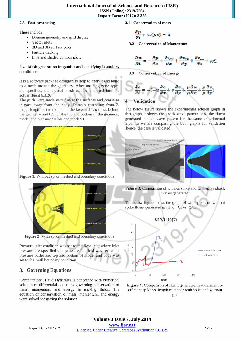
The below figure shows the experimental scleren graph in this graph it shows the shock wave pattern and the fluent generated shock wave pattern for the same experimental input so we are comparing the both graphs for validation .hence, the case is validated.
Figure 3: Comparison of without spike and with spike shock
waves generated
The below figure shows the graph of with spike and without spike fluent generated graph of Ch vs. X/L.
Figure 4: Comparison of fluent generated heat transfer co-efficient spike vs. length of 50 bar with spike and without
spike
Paper ID: 020141252 1235

International Journal of Science and Research (IJSR) ISSN (Online): 2319-7064
Impact Factor (2012): 3.358
Volume 3 Issue 7, July 2014 www.ijsr.net
Licensed Under Creative Commons Attribution CC BY
4. Results and Comparisons
A. Temperature contour plots of without spike
From the temperature contour observe that temperature is maximum at just ahead of the blunt body without spike and at the starting point of the bow shock temperature is about the 820k .This shock wave scatter the heat into the flow field so temperature decreases along the body.
Figure 5: Temperature contour Profile of without spike 50 bar
B. Temperature contour plots of with spike
From the below contour with spike blunt body temperature at the nose starting point is 625 k. The shock wave scattered along the length and decreases the temperature along physical domain.
Figure 6: Temperature contour plots of with spike 50 bar
C. Pressure contours plots of without spike
From the pressure contour observe that pressure is maximum at just ahead of the blunt body without spike and at the starting point. Without spike body bow shock pressure is about the 0.4020 pa. This shock wave scatters the heat into the flow field so pressure decreases along the body and with spike nose pressure is 0.208 pa.
Figure 8: Pressure profile of without spike model 50 bar
Figure 9: Pressure profile of with spike model 50 bar
D. Variation of Ch vs. length for without-spike 50 bar graph
Figure 10: Variation of Ch for length for without spike case
50 bar From the graph shows the variation of Ch with respect to different length as we increase the Ch along the length and there is sudden decrease for half of the body length and gradually decreases’ along the body length.
Paper ID: 020141252 1236

International Journal of Science and Research (IJSR) ISSN (Online): 2319-7064
Impact Factor (2012): 3.358
Volume 3 Issue 7, July 2014 www.ijsr.net
Licensed Under Creative Commons Attribution CC BY
E. Variation of Ch vs. length for with-spike 50 bar with spike graph
Figure 11: Variation of Ch for length for with spike case
The above graph shows the variation of Ch with respect to different length as increases the Ch along the length and there is sudden decrease for half of the body length and gradually increases and maintains constant profiles and starts decrease to the certain length along the body length.
F. Variation of heat flux vs temperature for without spike
Figure 12: Variation of heat flux for temperature for without
spike
G. Variation of heat flux vs. temperature for without spike
Figure 13: Variation of heat flux for temperature for with
spike From graphs figure: 12 and figure: 13 show the variation of maximum temperature with respect to heat flux as decrease and the pressure increasing.
H. Variation of temperature vs. length of the without spike model
Figure 14: Comparison of temperature vs. model length of
without spike
I. Variation of temperature vs. length of the with spike model
Figure 15: Comparison of temperature vs. model length
with spike
6. Conclusions
In spite of the decades of research into hypersonic flow, there are still many challenges to analyzing and designing high-speed vehicles. Recent events such as the Columbia accident are clear evidence that there are still “unknown unknowns” in the field of hypersonic flight that even our best experimental or numerical analysis cannot adequately predict. While analyzing both without and with spiked hypersonic vehicle the temperature of the spiked vehicle reduces at the nose due to reduction in the bow shock wave and also pressure of the nose vehicle so that there is less possibility or more time to take disaster of the hypersonic re-entry vehicles.
Paper ID: 020141252 1237

International Journal of Science and Research (IJSR) ISSN (Online): 2319-7064
Impact Factor (2012): 3.358
Volume 3 Issue 7, July 2014 www.ijsr.net
Licensed Under Creative Commons Attribution CC BY
7. Scope for future work
Introduction of spike in hypersonic vehicles are there. Since work have been going in the hypersonic vehicle. Very few people are doing work on introducing spike on the hypersonic re-entry vehicle. Since No static temperature data exists for Mach number in the range 8-14. Also data on large nose radius do not exist. Keeping in view of future requirements in the country as well as to generate data base towards extending some of existing static temperature ,correlations , a detailed CFD study of hypersonic laminar surface flows on several spiked models this will have relevance to reentry missions.
References [1] Ferry F.J. Schrijer and Fulvio Scarano and Bas W. van
Oudheusden [1] “Experiment on Hypersonic Boundary Layer Separation and Reattachment on a Blunted Cone-Flare using Quantitative InfraRed Thermography” 2003.
[2] Antonio Viviani and Giuseppe Pezzella [2] “Heat Transfer Analysis for a Winged Reentry Flight Test Bed” 2005.
[3] M.Y.M. Ahmeda N. Qin [3] “Recent advances in the aerothermodynamics of spiked hypersonic vehicles” 2011
[4] Zonglin Jiang and Yunfeng Liu and Guilai Han [4] “Drag reduction under non-zero attack angles and avoid the severe aerodynamic heating, a new concept of the Non-ablative Thermal Protection System (NaTPS) for hypersonic vehicle”. 2011.
[5] N.Sreenivasa Babu. Dr. K. Jayathirtha Rao [5] “Aerodynamic drag and heating are the crucial in the thermal stability of hypersonic vehicles at various speeds”
[6] Agosh M C[6] “Experiment Aerodynamic and Heat Transfer Analysis Over Spherical Blunt Cone”
[7] Niranjan Sahoo [7] “Experiments on a Blunt Cone Model in a Hypersonic Shock Tunnel” (2007).
[8] Zonglin Jiang Yunfeng Liu Guilai Han· Wei Zhao [8] “Experimental demonstration of a new concept of drag reduction and thermal protection for hypersonic vehicles”
[9] Dr.B.Balakrishna, S. Venkateswarlu, Dr P. Ravinder Reddy.Flow [9] “Analysis of an Atmosphere Reentry Vehicle”(2012).
[10] J.M.A. Longo[10] “Modeling of hypersonic flow phenomena”(2004).
[11] Fei Li, Meelan Choudhari, Chau-Lyan Chang and Jeffery white [11] “Boundary Layer Transition over Blunt Hypersonic Vehicles Including Effects of Ablation-Induced Out-Gassing”
[12] Zonglin Jiang, Yunfeng Liu and Guilai Han [12] “Experiment for Conceptual Study on Non-ablative TPS for hypersonic vehicle”
Paper ID: 020141252 1238