aesculap orthopaedics targon rf - … rf_eng.pdf · ulcers in the trochanter region, ankylosis and...
TRANSCRIPT
Aesculap OrthopaedicsTargon® RF
Retrograde Femoral Nail

2
Retrograde Femoral Nail
The implantation of interlocking nails from an antegrade access hasbecome the gold standard for most fractures of the femoral shaft.In the interests of optimally expanding the indications for the ante-grade procedure, the distal interlocking holes have been moved a great distance toward distal and tripled in number in the Targon®
Femoral System. Nevertheless, there are still a number of very goodor relative indications for the retrograde nailing procedure.
Today supracondylar and transcondylar femoral fractures (Type Aand C of the AO Classification) constitute recognized indicationsfor retrograde nailing. The advantage of intramedullary fixation ofthese fractures lies in the lower demands placed on the lateral articular layers of the distal femur in comparison with the soft-tissue preparation required for extramedullary implant support. Because this procedure is only minimally invasive, pain-freemobilization of the knee joint is achieved very soon after surgery.
The new retrograde femoral nailing system is based on clear-cutand safe surgical steps. The nail design and instrumentation makeboth primary internal knee damage (caused by bore dust) and secondary internal damage (due to protruding edges of the distalnail tip) highly improbable. The screws have a strong design thatcan withstand prolonged maximum loads. With a new type of threaded sleeve, osteoporotic bone structure is no longer an obstacleto nailing. This reduces the danger of secondary protrusion of the implant into the knee joint and of screw loosening resulting in consecutive loss of reduction. For most forms of distal meta-physeal femoral fractures, the system offers the possibility of fixa-ting the nail additionally at the distal end of the shaft fragment;this "transfixation” is an effective way to neutralize the forces acting on the fracture zone. In particular, it promotes the endostealfracture-healing processes in the metaphysis.

3
A long-nail version is available for the retrograde nailing of shaftfractures; this version is interlocked in the sagittal direction in theproximal femoral region. There are several recommended or evenunavoidable indications for this procedure: e.g. "floating knee”,fractures seen in persons with extremely severe injuries, decubitalulcers in the trochanter region, ankylosis and arthrodesis of the hip joint, etc.
The retrograde nail rounds off the fixation options offered by theTargon® System for femoral fractures.
April, 2008
Priv. Doz. Dr. H.-W. StedtfeldCentre for Trauma Surgery, NurembergPriv. Doz. Dr. H.-W. StedtfeldCentre for Trauma Surgery, Nuremberg

Shearing motions in the fracture area?The transfixation of the fracture on the distal shaft fragment via the fourth screw cancels shearing motionsbetween the metaphyseal and shaft fragments.
Reaming debris in the knee joint?The distribution of reaming debris in the knee joint is avoided by opening the joint with the hollow reamer.
Internal knee damage caused by implant protrusion?Sufficiently recessed placement of the implant preventsprotruding implant edges. As a result of the ventral and dorsal oblique surfaces of the Targon® RF, the nail recess can be kept small, leaving more space for interlocking.
Angular play in the metaphysis?Angular play in the metaphysis and screw sliding can cause excessive instability in the fracture area. This is prevented by locking the distal screw with the closure screw.
Solves the problems posed by surgical treatment of the femur from a retrograde access
4

Deviation of nail curvature from anatomical curvature?If the proximal locking holes are located to one side of the large femoral shaft diameter, the groundwork is laid for incorrect drillings. Incorrect drillings are distinctly reduced by the anatomical curvature of the nail.
Screw loosening in patients with osteoporosis?The threaded sleeves, which can be used on both sides of the metaphysis, counteract the insufficiently secure screw seating which can be a problem in patients with osteoporosis.
Excessive intramedullary pressure?The long grooves exert a drainage effect, which lowers the medullary pressure during nail insertion.
5

6
The Implant
Implant material:Titanium alloy Ti6Al4V
Special nail tip design
facilitates implantation into the cancellous trochanteric region
Long grooves
result in higher elasticity and therefore a more favorable distribution of forces, thereby lessening the danger of fracture
accelerate regeneration of the endosteal blood supply
help to alleviate pressure during the implantation of the nail
Anatomical nail design
easy nail implantation
central position of thelocking holes in the medullary canal
4-way interlocking
possibility for placing the transfixation screws
optimal fracture stabilization
Ventrodorsal nail tip
prevents nail protrusion in the knee joint

7
Interlocking screws
extremely strong titanium alloy with a proven design
Closure screw
locks the distal screw to prevent screw sliding and angular metaphyseal movement
The threaded sleeve ensures secure screw fixation in patients with osteoporosis
internal thread for secure connection between the threaded sleeve and the screw (dia. 6 mm)
self-tapping outer threadensures large-area bone contact
Surgical Manual
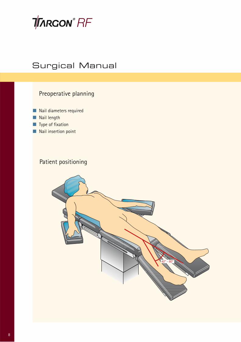
Preoperative planning
Nail diameters required Nail length Type of fixationNail insertion point
Patient positioning
8
40° - 60°

9
Access and preparation of the nail bed
Access
Hollow reamer (Ø 12.5 mm) KH392R
Guide pin KH393R
Universal handle KH319R
Cutaneous incision and tissue splitting. Insertthe guide pin with the universal handle or amotor-driven instrument; monitor the positionwith an image intensifier. Open the entry holewith the hollow reamer.
2
1
Nail insertion
Attaching the nail to the targeting device
Targeting device KH210
Nail adapter KH396R
Nail adapter screw KH397R
Tightening sleeve KH321R
Connect the nail adapter to the targeting device. Insert the nail adapter screw until above the light pressure point. Attach the selected nail, tighten by hand with the tightening sleeve. Pay attention to the curvature of the nail and the lateral position of the targeting device.
Surgical Manual
10
3
4
5
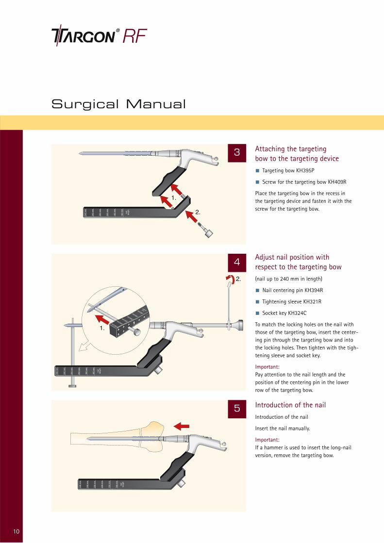
Attaching the targeting bow to the targeting device
Targeting bow KH395P
Screw for the targeting bow KH409R
Place the targeting bow in the recess in the targeting device and fasten it with the screw for the targeting bow.
Adjust nail position with respect to the targeting bow
(nail up to 240 mm in length)
Nail centering pin KH394R
Tightening sleeve KH321R
Socket key KH324C
To match the locking holes on the nail withthose of the targeting bow, insert the center-ing pin through the targeting bow and intothe locking holes. Then tighten with the tigh-tening sleeve and socket key.
Important:Pay attention to the nail length and the position of the centering pin in the lower row of the targeting bow.
Introduction of the nail
Introduction of the nail
Insert the nail manually.
Important:If a hammer is used to insert the long-nailversion, remove the targeting bow.
240 mm 240 mm 200 mm 200 mm 160 mm 160 mm nail length

11
6
Distal interlocking
Drilling
Screw sleeve KH410P
Tissue-protection sleeve KH429R
Obturator KH383R
Twist drill (Ø 5 mm) KH385R
Screw the screw sleeve into the targeting bow. Insert the tissue-protection sleeve. Make the stab incision. Widen the incision.Using the obturator, advance the tissue-protection sleeve up to the bone. Drill open the screw hole with the twist drill (Ø 5 mm).
Important:It is essential to follow this sequence. Do notchange the flexion position of the knee, sincethis could pull the tissue protection sleevethrough the iliotibial tract and cause a drillingerror.
7
Precise positioning of the nail
Nail depth scale KH406R
Check the nail position with an image intensifier. Push the nail depth scale over the targeting device up to the condyles. The insertion depth of the nail (0 - 10 mm)can be read in the window of the nail depth scale.
160 mm nail length

12
Surgical Manual
8 Interlocking
Screw scale KH274R
Screwdriver KH322R
Determine the screw length with the screw scale. The length shown determines the distance between the cortical layers. Insert the selected screw (Ø 6 mm) with the screwdriver.
Important:Do not manipulate using force! This couldresult in misalignment of the guide wire and the nail hole for proximal locking.
0 5
9 Lateral use of the threaded sleeve
Counterhandle KH405R
Screwdriver KH322R
Screw the threaded sleeve onto the selectedscrew by hand. Tighten the connection withthe counterhandle and screwdriver.
Important:Before inserting the threaded sleeve from medial, insert all the required lateral screws.This prevents unnecessary moving of the targeting bow.
13
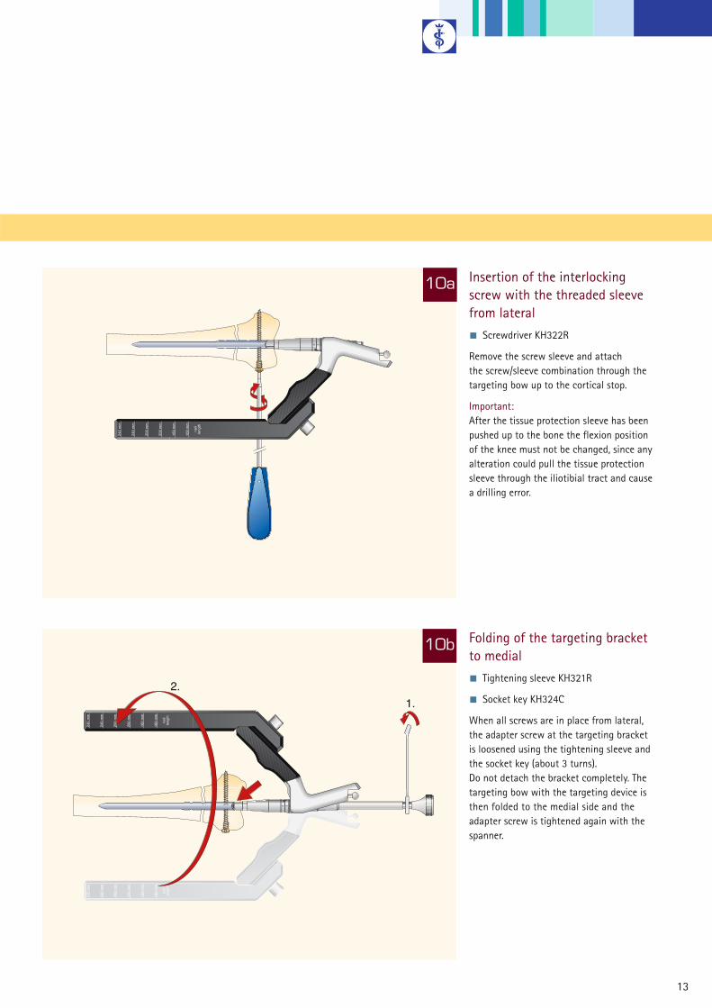
10a Insertion of the interlocking screw with the threaded sleevefrom lateral
Screwdriver KH322R
Remove the screw sleeve and attach the screw/sleeve combination through the targeting bow up to the cortical stop.
Important:After the tissue protection sleeve has beenpushed up to the bone the flexion position of the knee must not be changed, since any alteration could pull the tissue protectionsleeve through the iliotibial tract and cause a drilling error.
Folding of the targeting bracket to medial
Tightening sleeve KH321R
Socket key KH324C
When all screws are in place from lateral, the adapter screw at the targeting bracket is loosened using the tightening sleeve and the socket key (about 3 turns). Do not detach the bracket completely. The targeting bow with the targeting device isthen folded to the medial side and the adapter screw is tightened again with thespanner.
10b

Surgical Manual
14
11 Insertion of the threaded sleevefrom medial
Inserter for threaded sleeve KH404R
Remove the screw sleeve from the targetingbow. Screw in the threaded sleeve with thesleeve driver up to the cortical stop.

15
12 Proximal interlocking
Preparation of the entry cortex with the facing cutter
(nail up to 240 mm in length)
Facing cutter KH376R
Tissue protection sleeve KH429R
Obturator KH383R
Insert the tissue protection sleeve. Make thestab incision. Widen the incision. Advance thetissue protection sleeve with the obturator upto the bone. Prepare the shaft cortex with thefacing cutter.
13 Drilling for interlocking screws
(nail up to 240 mm in length)
Twist drill (Ø 4 mm) KH384R
Screw scale KH274R
Screwdriver KH322R
Drill open the cortex with the twist drill (Ø 4.0 mm). Determine the screw length with the screw scale. Screw in the selectedinterlocking screw (Ø 4.5 mm).

16
Surgical Manual
14
15
Freehand interlocking
(nails from 300 - 460 mm length)
Centering drill KH265R
Twist drill (Ø 3.5 mm) KH267R
For nail lengths of 300 mm and above, proximal anteroposterior interlocking shouldbe carried out with the free-hand technique.Care should be taken here to select the naillength such that the proximal interlockinglies flat in the area of the greater and lessertubercle.
Removal of the targeting bow
Tightening sleeve KH321R
Socket key KH324C
Screwdriver KH322R
The connecting screw between the targeting bow and the targeting device can be loosened with the screwdriver. Loosen the nail adapter screw and removethe targeting device with the adapter.

17
Insertion of the closure screw
Screwdriver KH322R
Screw in the closure screw with thescrewdriver until the distal interlockingscrew is firmly locked.
Removal of metal
Screwdriver KH322R
Inserter for threaded sleeve KH404R
Extractor adapter KH311R
Extractor instrument KH310R
Slotted hammer KH113R
The patient should be placed in the same positioning as for implantation. It should be assumed that there is bony overgrowth of the distal nail tip.After opening the joint via the old scar,introduce the guide pin centrally in the nail hole; monitor with the imageintensifier. Cautiously expose the distalnail tip with the hollow reamer. Removethe closure screw and the distal andproximal interlocking screws.Screw in the extractor adapter. Removethe nail with the aid of the extractor instrument and the slotted hammer.
17
17
16

Article No. Description
A KH393R Guide pinB KH392R Hollow reamer Ø 12.5 mmC KH319R Universal handleD KH210R Targeting deviceE KH396R Nail adapterF KH397R Nail adapter screwG KH321R Tightening sleeve 10 width across flatsH KH324C Socket key 10 width across flatsI KH394R Nail centering pinJ KH395P Targeting bowK KH409R Screw for targeting bowL KH410P Screw sleeveM KH406R Nail depth scale
Set 1
18
Instrument Overview
240 mm
240 mm
200 mm
200 mm
160 mm
160 mm
naillength
0 5 10
A
B
D
L
M
HE
G
FJ
K
C
I

19
Article No. Description
Set 2
A KH385R Twist drill Ø 5 mmB KH404R Inserter for threaded sleeveC KH405R Counter handleD KH274R Screw scaleE KH322R Screw driverF KH383R ObturatorG KH267R Twist drill Ø 3.5 mmH KH265R Centering drillI KH429R Tissue protection sleeveJ KH376R Facing cutterK KH384R Twist drill Ø 4 mm
A
B
K
F
C
E
D
HI
G
J

20
Instrument Sets
Quant. Article No. Description
KH334
recommended container for KH334 with lid: JK442 + JK 489 (lid)recommended lid for basket: JF217R
1 KH210R Targeting device
1 KH397R Nail adapter screw
1 KH396R Nail adapter
1 KH395P Targeting bow
1 KH321R Tightening sleeve 10 width across flats
1 KH324C Socket key 10 width across flats
1 KH319R Universalhandle
1 KH394R Nail centering pin
1 KH392R Hollow reamer Ø 12.5 mm
1 KH393R Guide pin
1 KH406R Nail depth scale
2 KH410P Screw sleeve
1 KH409R Screw for targeting bow
1 KH333R Basket with storage
1 JF511 Wrapping drape
1 TE600 Packing implate
1 KH408 X-Ray implate
Basic instrument set 1
21
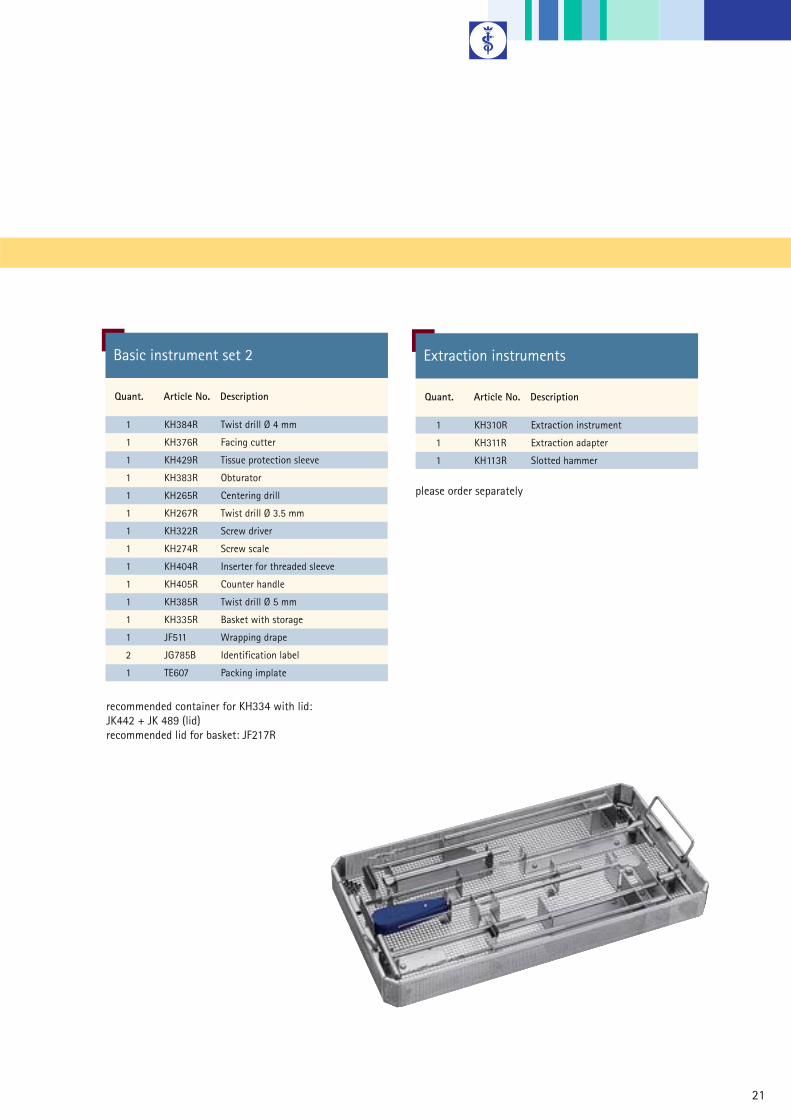
Quant. Article No. Description
1 KH310R Extraction instrument
1 KH311R Extraction adapter
1 KH113R Slotted hammer
Extraction instruments
please order separately
Quant. Article No. Description
1 KH384R Twist drill Ø 4 mm
1 KH376R Facing cutter
1 KH429R Tissue protection sleeve
1 KH383R Obturator
1 KH265R Centering drill
1 KH267R Twist drill Ø 3.5 mm
1 KH322R Screw driver
1 KH274R Screw scale
1 KH404R Inserter for threaded sleeve
1 KH405R Counter handle
1 KH385R Twist drill Ø 5 mm
1 KH335R Basket with storage
1 JF511 Wrapping drape
2 JG785B Identification label
1 TE607 Packing implate
Basic instrument set 2
recommended container for KH334 with lid: JK442 + JK 489 (lid)recommended lid for basket: JF217R

22
Implant Sets
Quant. Art. No. Spezification: Ø, Length
1 KD902T 10 x 160 mm
1 KD904T 10 x 200 mm
1 KD906T 10 x 240 mm
1 KD388T 10 x 300 mm
1 KD390T 10 x 320 mm
1 KD392T 10 x 340 mm
1 KD394T 10 x 360 mm
1 KD396T 10 x 380 mm
1 KD398T 10 x 400 mm
1 KD400T 10 x 420 mm
1 KD402T 10 x 440 mm
1 KH337R Basket with storage
1 JF511 Wrapping drape
2 JG785B Identification label
1 TE606 Packing implate
Set for Targon® RF nails
recommended container for KH156 or KH154:JK440 + JK489 (lid)recommended lid for basket: JF217R
KH336
23
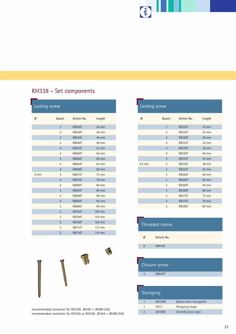
Ø Quant. Article No. Length
2 KB636T 36 mm
2 KB640T 40 mm
2 KB644T 44 mm
2 KB648T 48 mm
4 KB652T 52 mm
4 KB656T 56 mm
4 KB660T 60 mm
4 KB664T 64 mm
4 KB668T 68 mm
6 mm 4 KB672T 72 mm
4 KB676T 76 mm
4 KB680T 80 mm
4 KB684T 84 mm
4 KB688T 88 mm
4 KB692T 92 mm
2 KB696T 96 mm
2 KB700T 100 mm
2 KB704T 104 mm
2 KB708T 108 mm
2 KB712T 112 mm
2 KB716T 116 mm
Locking screw
Ø Quant. Article No. Length
2 KB320T 20 mm
2 KB324T 24 mm
2 KB328T 28 mm
4 KB332T 32 mm
4 KB336T 36 mm
4 KB340T 40 mm
4 KB344T 44 mm
4.5 mm 2 KB348T 48 mm
2 KB352T 52 mm
2 KB356T 56 mm
2 KB360T 60 mm
2 KB364T 64 mm
2 KB368T 68 mm
2 KB372T 72 mm
2 KB376T 76 mm
2 KB380T 80 mm
Locking screw
KH338 – Set components
recommended container for KH338: JK440 + JK489 (lid)recommended container for KH336 or KH338: JK444 + JK489 (lid)
Threaded sleeve
Ø Article No.
6 KB616T
Closure screw
2 KB630T
Storaging
1 KH339R Basket with storage/lid
1 JF511 Wrapping drape
2 JG785B Identification label

Implant Program
24
Ø Length Article No.
160 mm KD902T
200 mm KD904T
240 mm KD906T
300 mm KD388T
320 mm KD390T
10 mm 340 mm KD392T
360 mm KD394T
380 mm KD396T
400 mm KD398T
420 mm KD400T
440 mm KD402T
340 mm KD492T
360 mm KD494T
380 mm KD496T
11 mm 400 mm KD498T
420 mm KD500T
440 mm KD502T
460 mm KD504T
160 mm KD922T
12 mm 200 mm KD924T
240 mm KD926T
Targon® RF

25
Ø Length Article No.
36 mm KB636T
40 mm KB640T
44 mm KB644T
48 mm KB648T
52 mm KB652T
56 mm KB656T
60 mm KB660T
64 mm KB664T
68 mm KB668T
72 mm KB672T
6 mm 76 mm KB676T
80 mm KB680T
84 mm KB684T
88 mm KB688T
92 mm KB692T
96 mm KB696T
100 mm KB700T
104 mm KB704T
108 mm KB708T
112 mm KB712T
116 mm KB716T
Locking screw
Ø Length Article No.
20 mm KB320T
24 mm KB324T
28 mm KB328T
32 mm KB332T
36 mm KB336T
40 mm KB340T
44 mm KB344T
4.5 mm 48 mm KB348T
52 mm KB352T
56 mm KB356T
60 mm KB360T
64 mm KB364T
68 mm KB368T
72 mm KB372T
76 mm KB376T
80 mm KB380T
Locking screw
Threaded sleeve
Article No.
KB616T
Closure screw
Article No.
KB630T

26

27
All rights reserved. Technical alterations are possible. This leaflet may be used for no other purposes than offering, buying and selling of our products. No part may be copied or reproduced in any form. In the case of misuse we retain the rights to recall our catalogues and pricelists and to take legal actions.
Brochure No. O19002 0408/1/3
Aesculap AG & Co. KG
Am Aesculap-Platz78532 TuttlingenGermany
Phone +49 7461 95-0Fax +49 7461 95-2600
www.aesculap.de