af 202. objectives review airport layout and visual aids airport operations interception procedures
TRANSCRIPT

AF 202

Objectives
Review
Airport layout and visual aids
Airport operations
Interception Procedures
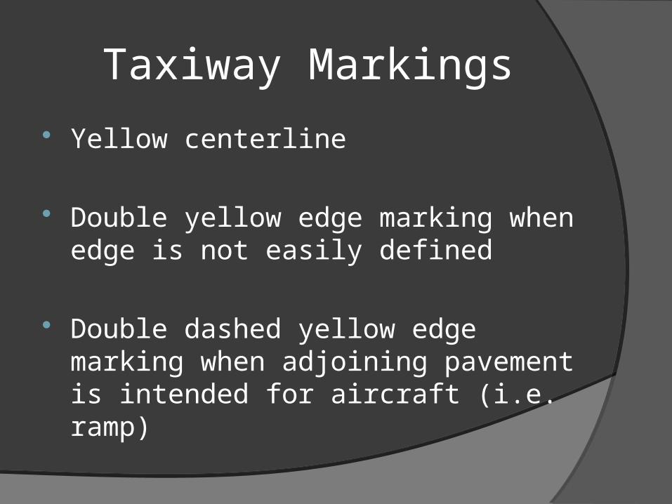
Taxiway Markings
Yellow centerline
Double yellow edge marking when edge is not easily defined
Double dashed yellow edge marking when adjoining pavement is intended for aircraft (i.e. ramp)
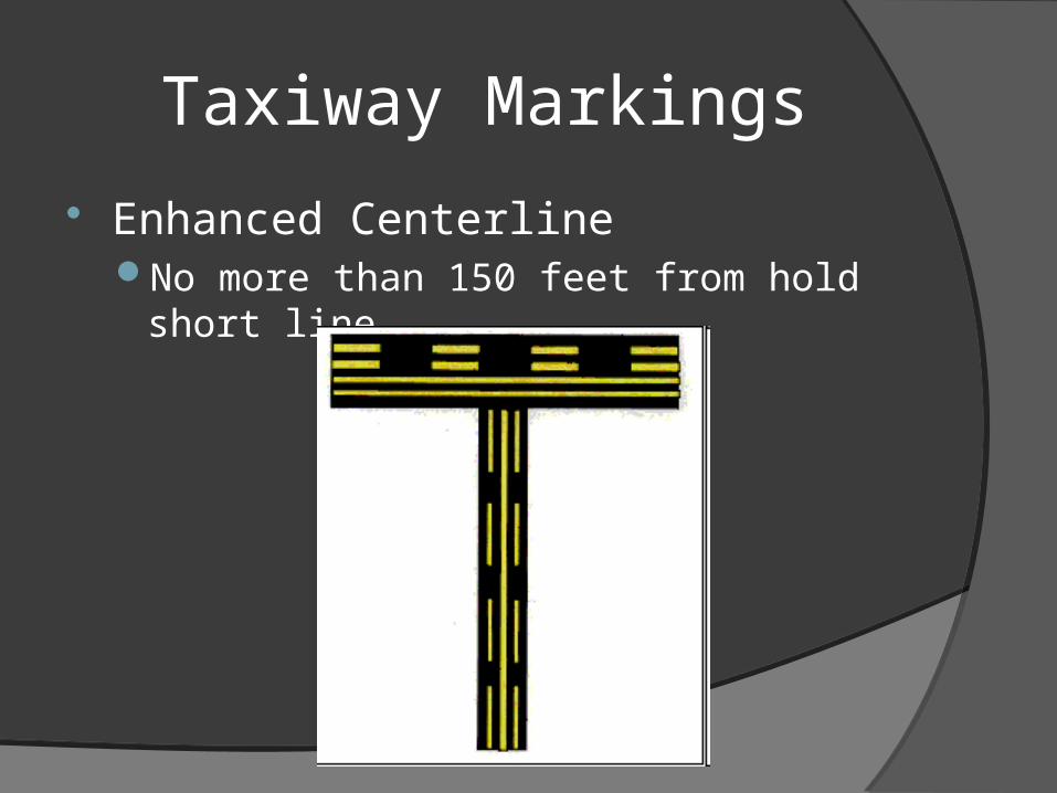
Taxiway Markings
Enhanced CenterlineNo more than 150 feet from hold short line

Hold Short
Runway Hold Short Line
ILS Hold Short Line

Hold Short
Hold short ofrunway approach

Taxiway Lighting
Edge Lights – Steady Blue
Centerline Lights – Steady Green
Clearance Bar Lights – 3 Steady YellowCan be located at taxiway Intersections

Taxiway Lighting
Runway Guard Lights – YellowAlternating lights next to taxiwayRow of in ground lights
Stop Bar Lights – Steady RedUsed in low visibilityIn pavement row of lightsUsed to confirm ATC clearance

Runway Markings
Runway DesignatorsPrinted magnetic direction‘L’ – Left ‘R’ – Right ‘C’ – Center
Runway Centerline
Runway Aiming point2 broad stripes 1000 ft from threshold
Runway Markings
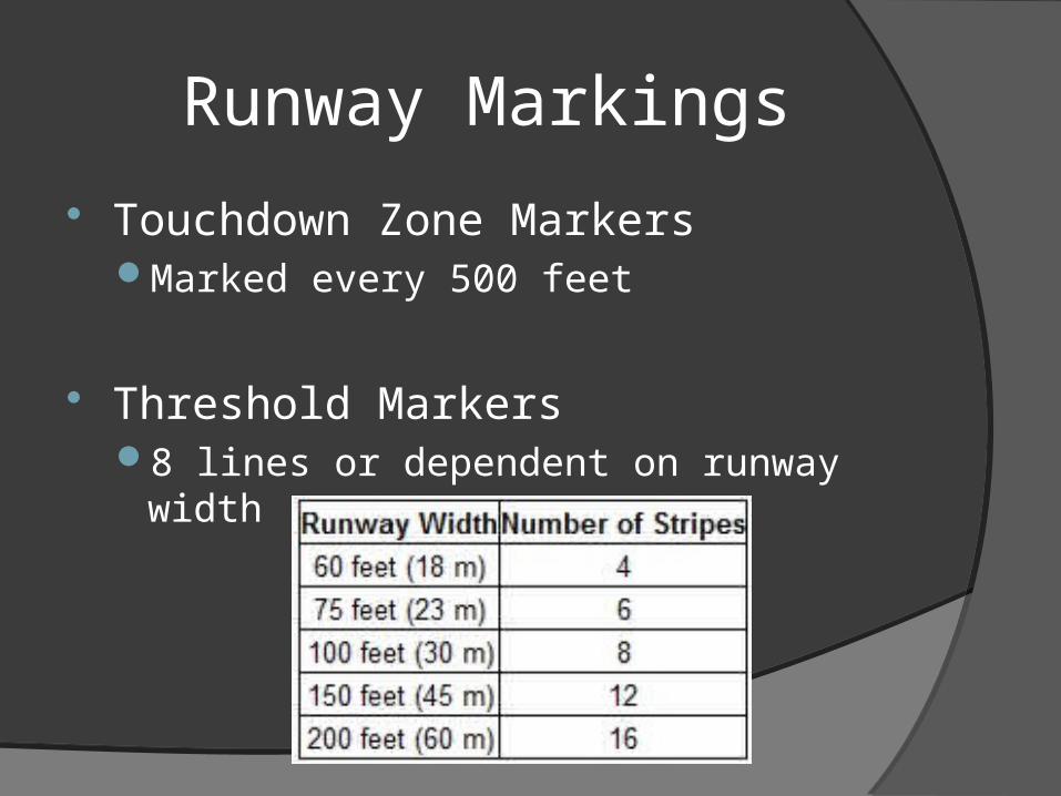
Touchdown Zone MarkersMarked every 500 feet
Threshold Markers8 lines or dependent on runway width

Runway Markings
Types of Runways

Runway Markings
Visual and Non-Precision
Runway Markings
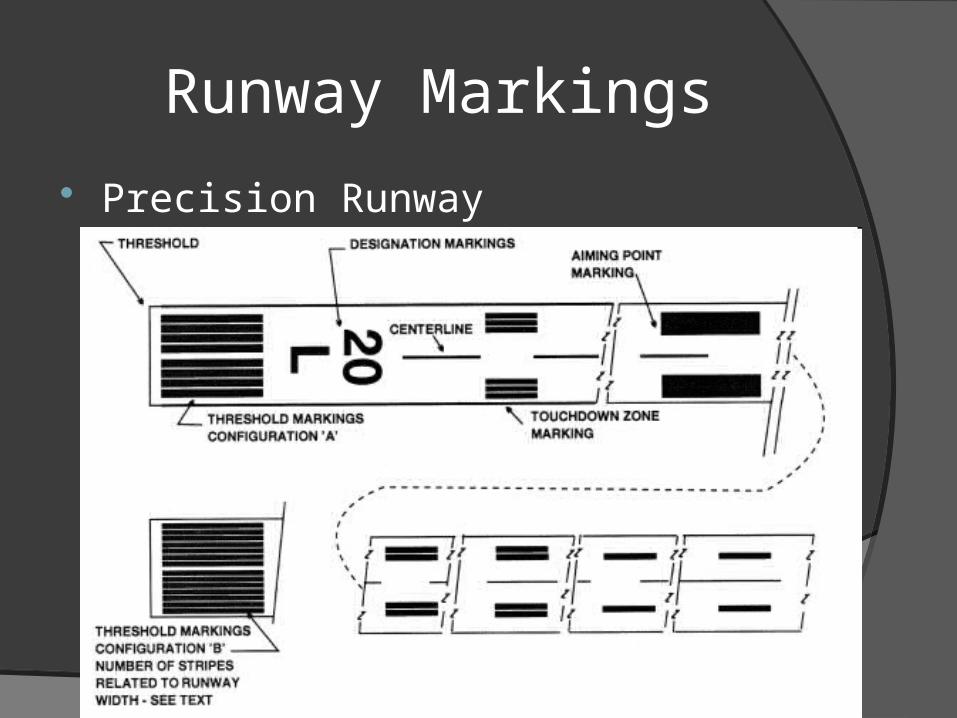
Precision Runway
Runway Markings
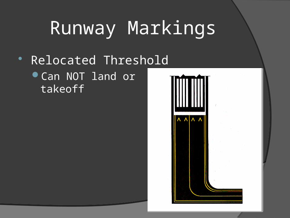
Relocated ThresholdCan NOT land or
takeoff

Runway Markings
Displaced ThresholdCan takeoffCan NOT land
Runway Markings
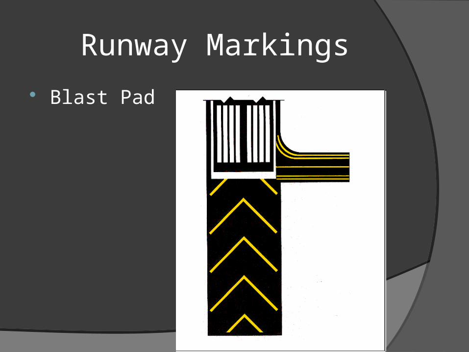
Blast Pad

Runway Markings
Combo Deal

Runway Markings
Closed
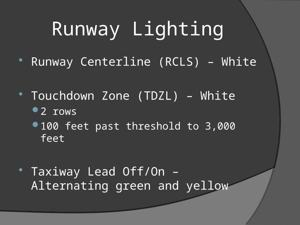
Runway Lighting
Runway Centerline (RCLS) – White
Touchdown Zone (TDZL) – White2 rows100 feet past threshold to 3,000 feet
Taxiway Lead Off/On – Alternating green and yellow
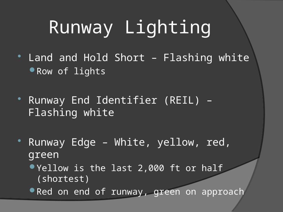
Runway Lighting
Land and Hold Short – Flashing whiteRow of lights
Runway End Identifier (REIL) – Flashing white
Runway Edge – White, yellow, red, greenYellow is the last 2,000 ft or half (shortest)Red on end of runway, green on approach
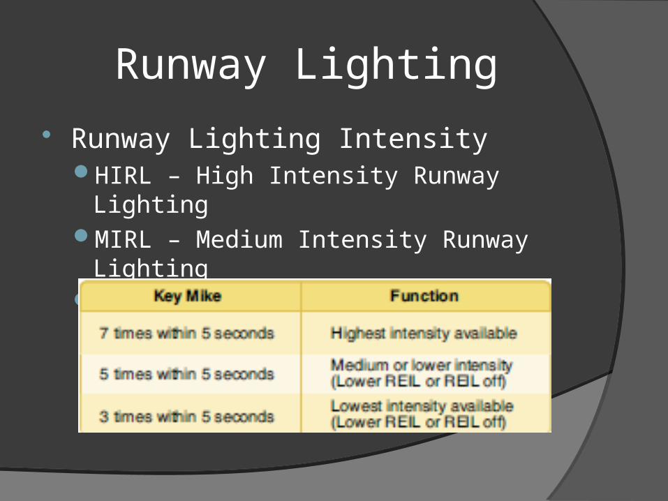
Runway Lighting
Runway Lighting IntensityHIRL – High Intensity Runway LightingMIRL – Medium Intensity Runway LightingLIRL – Low Intensity Runway Lighting

Runway Lighting
ApproachLights

Runway Lights (VASI variations)
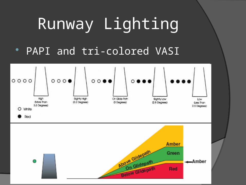
Runway Lighting
PAPI and tri-colored VASI

Runway Lighting
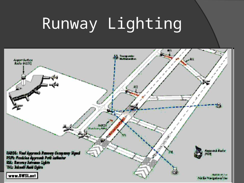
Runway Status Light (RWSL)Runway Entrance Lights
Takeoff Hold Lights
Final Approach Runway Occupancy signal○ Precision Approach Path Indicator (PAPI)
flashes if runway is occupied
Runway Lighting

Other Markings
Runway Holding Position
Holding Position (Beginning of Runway)

Other Markings
Holding Position for Approach Area
ILS Holding Area

Other Markings
Position (Location) markings
Direction (Destination) Markings

Other Markings
Runway Distance Remaining
Ground Receiver Checkpoint

Other Markings
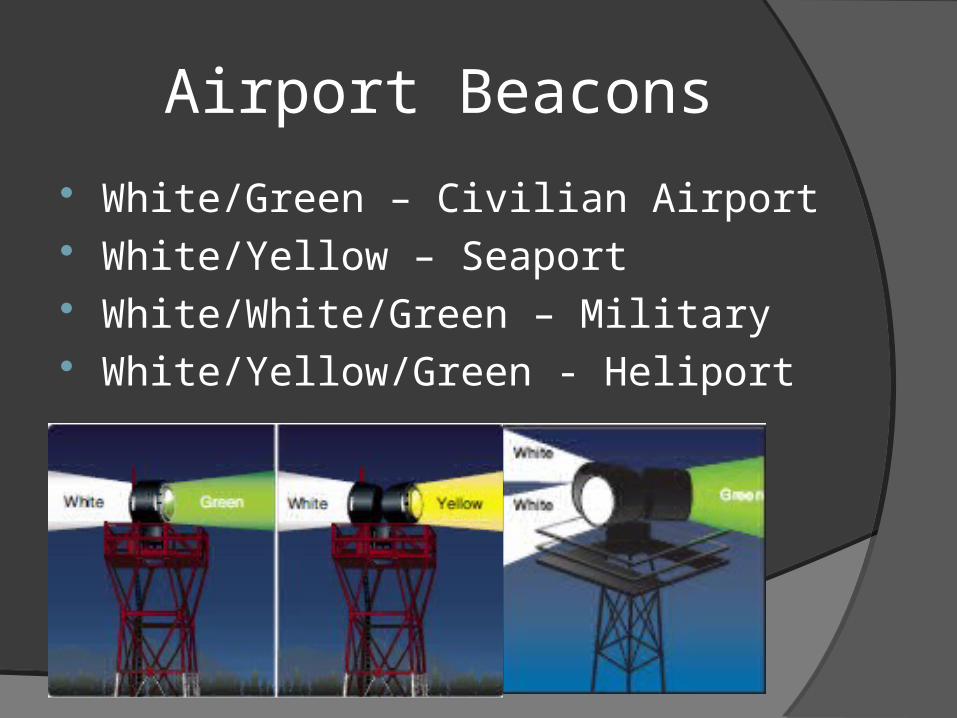
Airport Beacons
White/Green – Civilian Airport White/Yellow – Seaport White/White/Green – Military White/Yellow/Green - Heliport


Land And Hold Short
Controller can clear a pilot for LAHSO when there is an intersecting runway
Pilot must determine if there is enough Available Runway Distance
Pilot in Command has final authority to accept clearance (cannot be forced)

LAHSO – AF/D

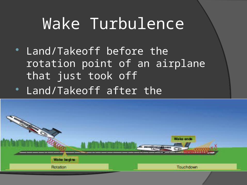
Wake Turbulence
Large Aircraft generate large wingtip vortices
Vortex generation is governed by weight, speed and shape of wingHeavy, slow, and clean configuration gives
the greatest vortex strength

Wake Turbulence
Small aircraft must be separated from large and heavy aircraft by 3 minutes
3 minute separate rule does not applyParallel runway father than 2500 ftWhen departure point is within 500 ftWhen PIC waivers the rule
3 minute rule cannot be waived if behind a heavy aircraft
Wake Turbulence
Land/Takeoff before the rotation point of an airplane that just took off
Land/Takeoff after the touchdown point of an airplane that just landed

Unexpected Maneuvers
ATC services is based on observed or known trafficControllers establish sequence and spacing
Controllers can anticipate minor maneuvers like ‘S’ turns
Controllers cannot anticipate 360 turnsMust request or be asked by ATC
Intersection Takeoffs
Pilots are expected to taxi to the beginning of the runway
Pilot can request intersection takeoff
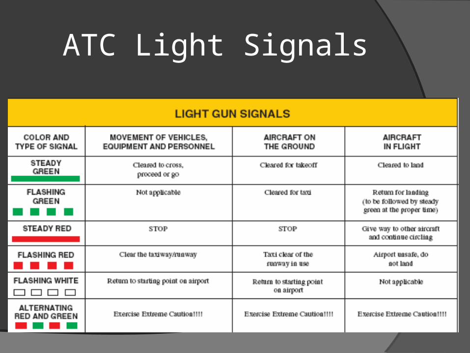
ATC Light Signals
Special VFR
Must be done in controlled airspace only
Clearance must be obtained from ATC when in class B, C, D airports
Clearance must be obtained from nearest tower, FSS, or center when in class E airport
Special VFR
Must be requested by pilot
Weather RequirementsVisibility of at least 1 statute mileRemain clear of clouds
At nightPilot and aircraft must be IFR certified
Surveillance Environment
Surveillance is available at class B, C and D TRSA (Terminal Radar Service Area)
Initial contact is made with approach control
Altitude should be reported along with position
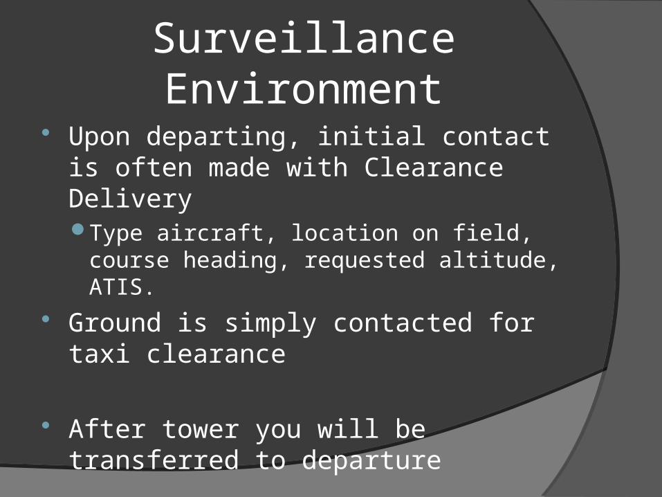
Surveillance Environment
Upon departing, initial contact is often made with Clearance DeliveryType aircraft, location on field, course
heading, requested altitude, ATIS.
Ground is simply contacted for taxi clearance
After tower you will be transferred to departure
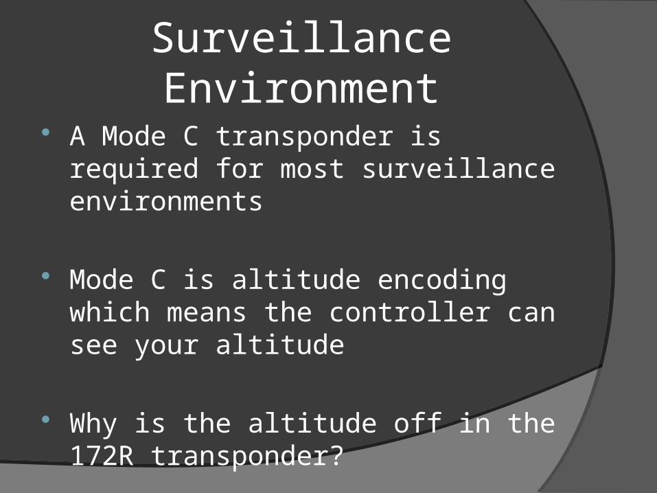
Surveillance Environment
A Mode C transponder is required for most surveillance environments
Mode C is altitude encoding which means the controller can see your altitude
Why is the altitude off in the 172R transponder?

Surveillance Environment
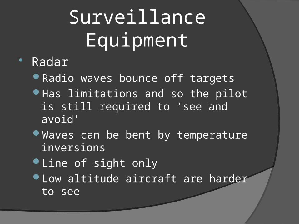
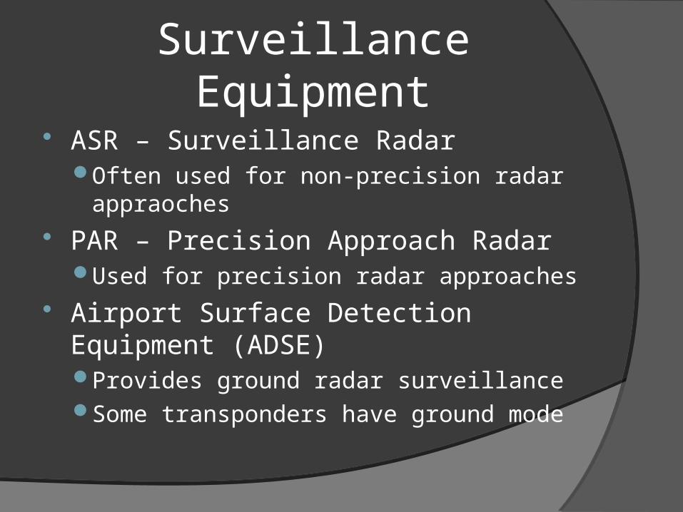
Surveillance Equipment
RadarRadio waves bounce off targetsHas limitations and so the pilot is still
required to ‘see and avoid’Waves can be bent by temperature
inversionsLine of sight onlyLow altitude aircraft are harder to see
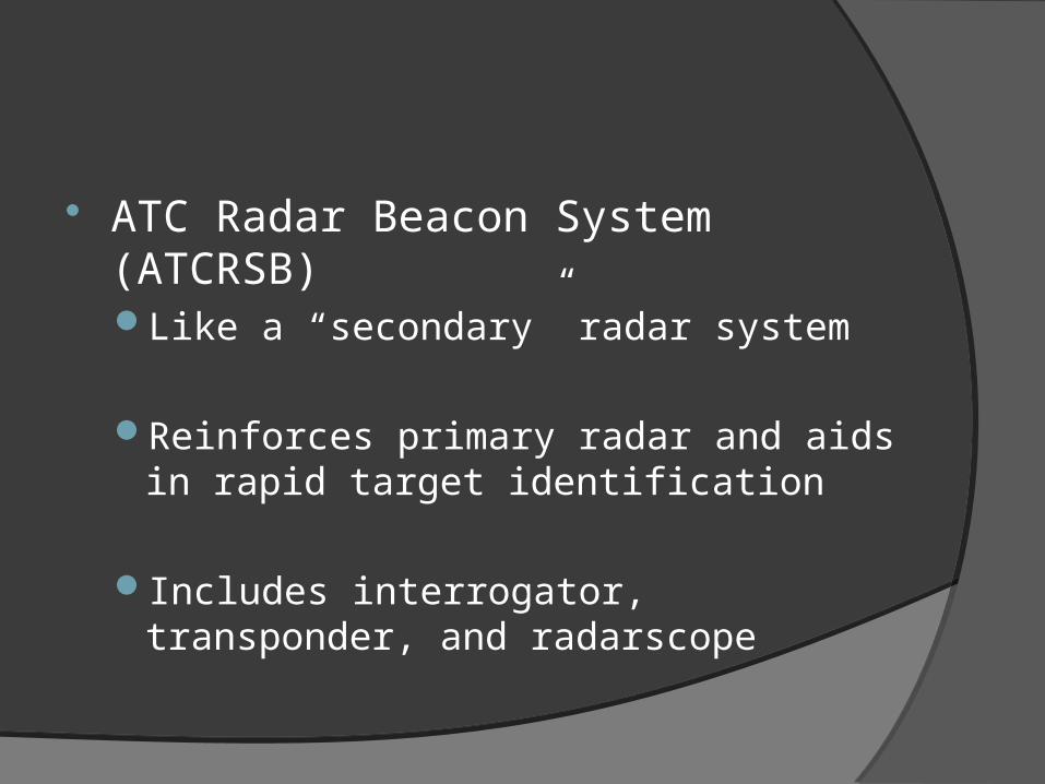
ATC Radar Beacon System (ATCRSB)Like a “secondary” radar system
Reinforces primary radar and aids in rapid target identification
Includes interrogator, transponder, and radarscope
Surveillance Equipment
ASR – Surveillance RadarOften used for non-precision radar
appraoches
PAR – Precision Approach RadarUsed for precision radar approaches
Airport Surface Detection Equipment (ADSE)Provides ground radar surveillanceSome transponders have ground mode
Interception Procedures
“Identification intercepts during peacetime operations are vastly different than those
conducted under increased states of readiness.”
Here are the peacetime procedures…


Interception Procedures

Interception Procedures
If intercepted contact air traffic control immediately or guard 121.5
“If the U.S. military intercepts an aircraft and flares are dispensed in the area of that aircraft, aviators will pay strict attention!!!!!!”

Interception Procedures
Phase OneAircraft will be approached from the sternTwo aircraft will attempt identification
Phase TwoIntercepted aircraft should expect to visually
acquire the lead interceptorThey will get closer to read your tail number
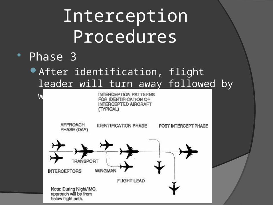
Interception Procedures
Phase 3After identification, flight leader will turn
away followed by wingman
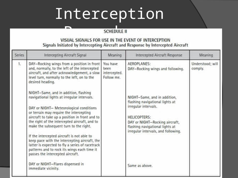
Interception Procedures

Interception Procedures
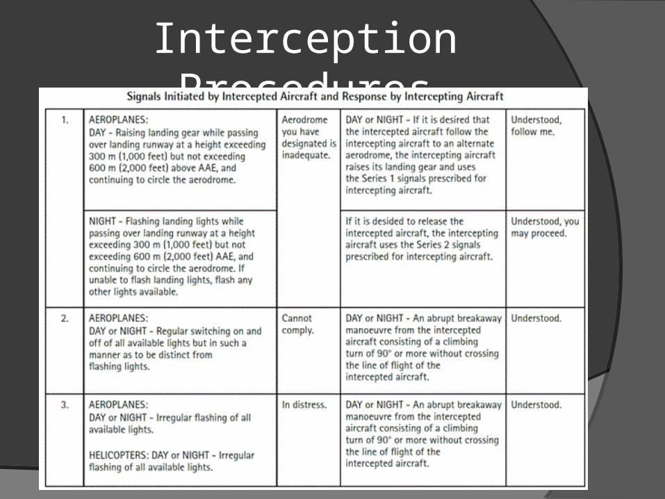
Interception Procedures

Peace out