af372ac electronic faucet installation and care guide
TRANSCRIPT
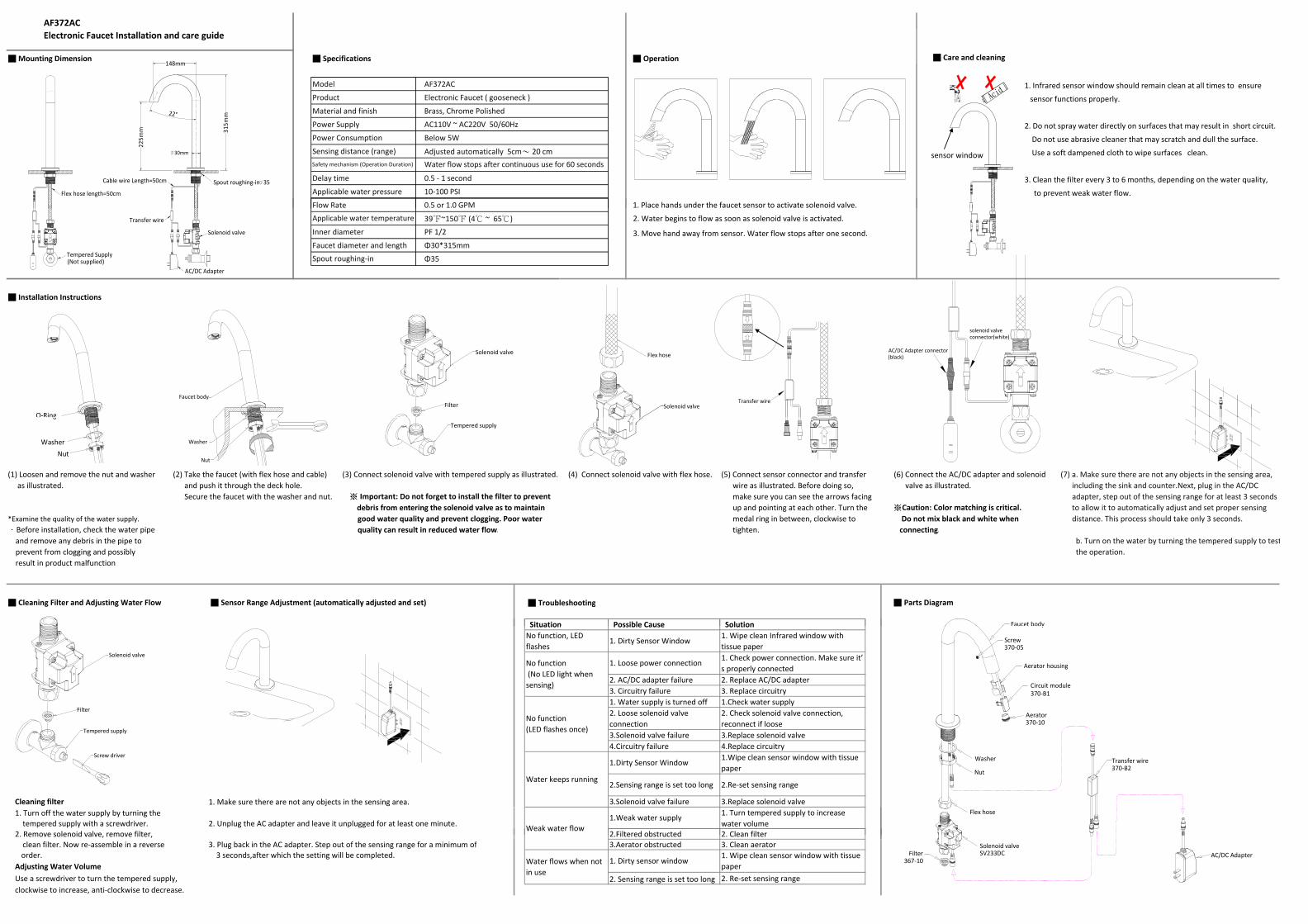
AF372ACElectronic Faucet Installation and care guide
■ Mounting Dimension ■ Specifications ■ Operation ■ Care and cleaning
Model AF372AC 1. Infrared sensor window should remain clean at all times to ensure Product Electronic Faucet ( gooseneck ) sensor functions properly.Material and finish Brass, Chrome Polished
Power Supply AC110V ~ AC220V 50/60Hz 2. Do not spray water directly on surfaces that may result in short circuit.Power Consumption Below 5W Do not use abrasive cleaner that may scratch and dull the surface.Sensing distance (range) Adjusted automatically 5cm~ 20 cm Use a soft dampened cloth to wipe surfaces clean.
Delay time 0.5 ‐ 1 second 3. Clean the filter every 3 to 6 months, depending on the water quality,Applicable water pressure 10‐100 PSI to prevent weak water flow. Flow Rate 0.5 or 1.0 GPM 1. Place hands under the faucet sensor to activate solenoid valve.
Safety mechanism (Operation Duration) Water flow stops after continuous use for 60 secondssensor window
Acid
225m
m
148mm
22°
315m
m
Cable wire Length=50cm Spout roughing‐in 35
30mm
Flex hose length=50cm
39℉~150℉ (4℃ ~ 65℃) 2. Water begins to flow as soon as solenoid valve is activated.
Inner diameter PF 1/2 3. Move hand away from sensor. Water flow stops after one second.Faucet diameter and length Φ30*315mm
Φ35
■ Installation Instructions
Spout roughing‐in
Applicable water temperature
Solenoid valve
FilterFaucet body
O‐Ring
Flex hose
Solenoid valveTransfer wire
solenoid valveconnector(white)
AC/DC Adapter connector(black)
(Not supplied)
Transfer wire
Tempered Supply
AC/DC Adapter
Solenoid valve
(1) Loosen and remove the nut and washer (2) Take the faucet (with flex hose and cable) (3) Connect solenoid valve with tempered supply as illustrated. (4) Connect solenoid valve with flex hose. (5) Connect sensor connector and transfer (6) Connect the AC/DC adapter and solenoid (7) a. Make sure there are not any objects in the sensing area, as illustrated. and push it through the deck hole. wire as illustrated. Before doing so, valve as illustrated. including the sink and counter.Next, plug in the AC/DC
Secure the faucet with the washer and nut. ※ Important: Do not forget to install the filter to prevent make sure you can see the arrows facing adapter, step out of the sensing range for at least 3 seconds debris from entering the solenoid valve as to maintain up and pointing at each other. Turn the ※Caution: Color matching is critical. to allow it to automatically adjust and set proper sensing
*Examine the quality of the water supply. good water quality and prevent clogging. Poor water medal ring in between, clockwise to Do not mix black and white when distance. This process should take only 3 seconds..Before installation, check the water pipe quality can result in reduced water flow. tighten. connecting. and remove any debris in the pipe to b. Turn on the water by turning the tempered supply to test prevent from clogging and possibly the operation. result in product malfunction
■ Cleaning Filter and Adjusting Water Flow ■ Sensor Range Adjustment (automatically adjusted and set) ■ Troubleshooting ■ Parts Diagram
Situation Possible Cause Solution
Tempered supply
Nut
Washer
NutWasher
O Ring
Faucet body Situation Possible Cause Solution
2. AC/DC adapter failure 2. Replace AC/DC adapter3. Circuitry failure 3. Replace circuitry1. Water supply is turned off 1.Check water supply
3.Solenoid valve failure 3.Replace solenoid valve4.Circuitry failure 4.Replace circuitry
Cleaning filter 1. Make sure there are not any objects in the sensing area. 3.Solenoid valve failure 3.Replace solenoid valve1. Turn off the water supply by turning the tempered supply with a screwdriver. 2. Unplug the AC adapter and leave it unplugged for at least one minute.2. Remove solenoid valve, remove filter, 2.Filtered obstructed 2. Clean filter
1. Wipe clean Infrared window withtissue paper
No function(LED flashes once)
2. Loose solenoid valveconnection
2. Check solenoid valve connection,reconnect if loose
2.Re‐set sensing range
1. Loose power connection
Water keeps running
No function (No LED light whensensing)
1.Dirty Sensor Window 1.Wipe clean sensor window with tissuepaper
2.Sensing range is set too long
1. Turn tempered supply to increasewater volumeWeak water flow
1. Dirty Sensor WindowNo function, LEDflashes
1. Check power connection. Make sure it’s properly connected
1.Weak water supply
Screw driver
Tempered supply
Filter
Solenoid valve
Screw370‐05
Washer
Nut
Flex hose
Aerator housing
Circuit module370‐B1
y
Aerator370‐10
Transfer wire370‐B2
2. Remove solenoid valve, remove filter, 2.Filtered obstructed 2. Clean filter clean filter. Now re‐assemble in a reverse 3. Plug back in the AC adapter. Step out of the sensing range for a minimum of 3.Aerator obstructed 3. Clean aerator
order. 3 seconds,after which the setting will be completed. Adjusting Water VolumeUse a screwdriver to turn the tempered supply, 2. Sensing range is set too long 2. Re‐set sensing rangeclockwise to increase, anti‐clockwise to decrease.
1. Dirty sensor window1. Wipe clean sensor window with tissuepaperWater flows when not
in use
AC/DC AdapterSolenoid valveSV233DCFilter
367‐10
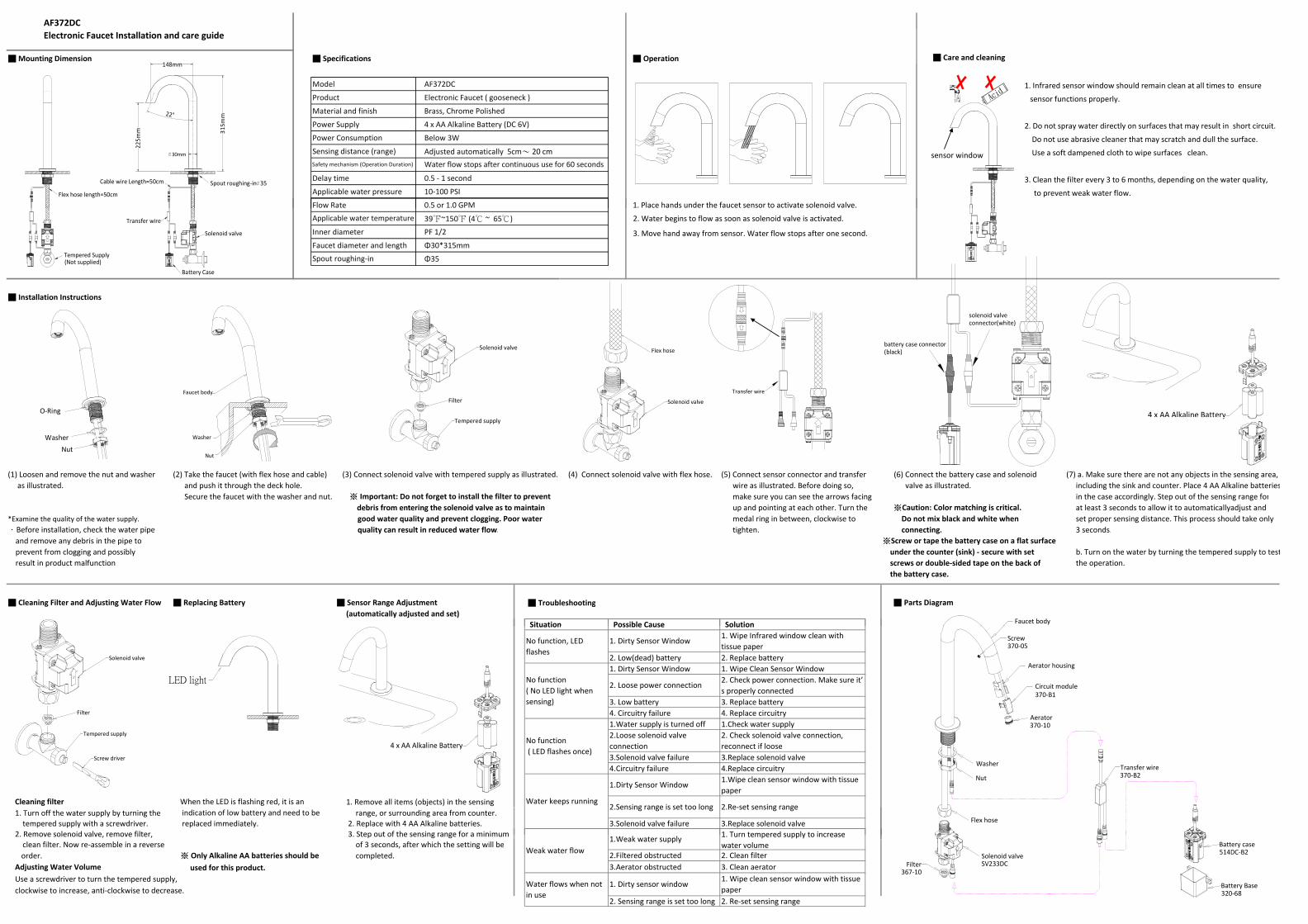
AF372DCElectronic Faucet Installation and care guide
■ Mounting Dimension ■ Specifications ■ Operation ■ Care and cleaning
Model AF372DC 1. Infrared sensor window should remain clean at all times to ensure Product Electronic Faucet ( gooseneck ) sensor functions properly.Material and finish Brass, Chrome Polished
Power Supply 4 x AA Alkaline Battery (DC 6V) 2. Do not spray water directly on surfaces that may result in short circuit.Power Consumption Below 3W Do not use abrasive cleaner that may scratch and dull the surface.Sensing distance (range) Adjusted automatically 5cm~ 20 cm Use a soft dampened cloth to wipe surfaces clean.
Delay time 0.5 ‐ 1 second 3. Clean the filter every 3 to 6 months, depending on the water quality,Applicable water pressure 10‐100 PSI to prevent weak water flow. Flow Rate 0.5 or 1.0 GPM 1. Place hands under the faucet sensor to activate solenoid valve.
Safety mechanism (Operation Duration) Water flow stops after continuous use for 60 secondssensor window
Acid
315m
m
Flex hose length=50cm
225m
m
22°
30mm
Spout roughing‐in 35
148mm
Cable wire Length=50cm
39℉~150℉ (4℃ ~ 65℃) 2. Water begins to flow as soon as solenoid valve is activated.
Inner diameter PF 1/2 3. Move hand away from sensor. Water flow stops after one second.Faucet diameter and length Φ30*315mm
Φ35
■ Installation Instructions
Applicable water temperature
Spout roughing‐in
Transfer wire
Solenoid valve
FilterFaucet body
O‐Ring
Flex hose
Solenoid valve
battery case connector(black)
solenoid valveconnector(white)
4 x AA Alkaline Battery
(Not supplied)Tempered Supply
Battery Case
Solenoid valve
Transfer wire
(1) Loosen and remove the nut and washer (2) Take the faucet (with flex hose and cable) (3) Connect solenoid valve with tempered supply as illustrated. (4) Connect solenoid valve with flex hose. (5) Connect sensor connector and transfer (6) Connect the battery case and solenoid (7) a. Make sure there are not any objects in the sensing area, as illustrated. and push it through the deck hole. wire as illustrated. Before doing so, valve as illustrated. including the sink and counter. Place 4 AA Alkaline batteries
Secure the faucet with the washer and nut. ※ Important: Do not forget to install the filter to prevent make sure you can see the arrows facing in the case accordingly. Step out of the sensing range for debris from entering the solenoid valve as to maintain up and pointing at each other. Turn the ※Caution: Color matching is critical. at least 3 seconds to allow it to automaticallyadjust and
*Examine the quality of the water supply. good water quality and prevent clogging. Poor water medal ring in between, clockwise to Do not mix black and white when set proper sensing distance. This process should take only .Before installation, check the water pipe quality can result in reduced water flow. tighten. connecting. 3 seconds. and remove any debris in the pipe to ※Screw or tape the battery case on a flat surface prevent from clogging and possibly under the counter (sink) ‐ secure with set b. Turn on the water by turning the tempered supply to test result in product malfunction screws or double‐sided tape on the back of the operation.
the battery case.
■ Cleaning Filter and Adjusting Water Flow ■ Replacing Battery ■ Sensor Range Adjustment ■ Troubleshooting ■ Parts Diagram (automatically adjusted and set)
Situation Possible Cause Solution
Tempered supply
Nut
Washer
NutWasher
y
Faucet body Situation Possible Cause Solution
2. Low(dead) battery 2. Replace battery1. Dirty Sensor Window 1. Wipe Clean Sensor Window
3. Low battery 3. Replace battery4. Circuitry failure 4. Replace circuitry1.Water supply is turned off 1.Check water supply
3.Solenoid valve failure 3.Replace solenoid valve4.Circuitry failure 4.Replace circuitry
Cleaning filter When the LED is flashing red, it is an 1. Remove all items (objects) in the sensing1. Turn off the water supply by turning the indication of low battery and need to be range, or surrounding area from counter. tempered supply with a screwdriver. replaced immediately. 2. Replace with 4 AA Alkaline batteries. 3.Solenoid valve failure 3.Replace solenoid valve2. Remove solenoid valve, remove filter, 3. Step out of the sensing range for a minimum
1.Dirty Sensor Window 1.Wipe clean sensor window with tissuepaper
2.Sensing range is set too long 2.Re‐set sensing range
k l 1. Turn tempered supply to increase
1. Wipe Infrared window clean withtissue paper
No function, LEDflashes
1. Dirty Sensor Window
Water keeps running
No function( No LED light whensensing)
2. Loose power connection 2. Check power connection. Make sure it’s properly connected
No function ( LED flashes once)
2.Loose solenoid valveconnection
2. Check solenoid valve connection,reconnect if loose4 x AA Alkaline Battery
Screw driver
Tempered supply
Filter
Solenoid valve
LED light
Screw370‐05
Aerator housing
Aerator370‐10
Circuit module370‐B1
Washer
Nut
Flex hose
Transfer wire370‐B2
2. Remove solenoid valve, remove filter, 3. Step out of the sensing range for a minimum clean filter. Now re‐assemble in a reverse of 3 seconds, after which the setting will be
order. ※ Only Alkaline AA batteries should be completed. 2.Filtered obstructed 2. Clean filterAdjusting Water Volume used for this product. 3.Aerator obstructed 3. Clean aeratorUse a screwdriver to turn the tempered supply,clockwise to increase, anti‐clockwise to decrease.
2. Sensing range is set too long 2. Re‐set sensing range
Water flows when notin use
1. Dirty sensor window1. Wipe clean sensor window with tissuepaper
Weak water flow1.Weak water supply 1. Turn tempered supply to increase
water volume
Battery Base320‐68
Solenoid valveSV233DCFilter
367‐10
Battery case514DC‐B2