affordable development and demonstration of a small … · space 2015 forum & exposition,...
TRANSCRIPT
AIAA-2015-4524
1 American Institute of Aeronautics and Astronautics
Space 2015 Forum & Exposition, Pasadena, CA, August 31 - September 2, 2015
Affordable Development and Demonstration of a Small NTR
Engine and Stage: How Small is Big Enough?
Stanley K. Borowski1, Robert J. Sefcik1, James E. Fittje2, David R. McCurdy2, Arthur L. Qualls3,
Bruce G. Schnitzler3, James E. Werner4, Abraham Weitzberg5 and Claude R. Joyner6
1NASA Glenn Research Center, Cleveland, OH 44135 2Vantage Partners, LLC at Glenn Research Center, Brook Park, OH 44142
3Oak Ridge National Laboratory, Oak Ridge, TN 3783 4Idaho National Laboratory, Idaho Falls, ID 83415
5DOE Consultant, 5711 Como Circle, Woodland Hills, CA 91367 6Aerojet Rocketdyne, West Palm Beach, FL 33410
telephone: (216) 977-7091, email: [email protected]
The Nuclear Thermal Rocket (NTR) derives its energy from fission of uranium-235 atoms
contained within fuel elements that comprise the engine’s reactor core. It generates high
thrust and has a specific impulse potential of ~900 seconds – a 100% increase over today’s
best chemical rockets. The Nuclear Thermal Propulsion (NTP) project, funded by NASA’s
AES program, includes five key task activities: (1) Recapture, demonstration, and validation
of heritage graphite composite (GC) fuel (selected as the “Lead Fuel” option); (2) Engine
Conceptual Design; (3) Operating Requirements Definition; (4) Identification of Affordable
Options for Ground Testing; and (5) Formulation of an Affordable Development Strategy.
During FY’14, a preliminary DDT&E plan and schedule for NTP development was outlined
by GRC, DOE and industry that involved significant system-level demonstration projects
that included GTD tests at the NNSS, followed by a FTD mission. To reduce cost for the
GTD tests and FTD mission, small NTR engines, in either the 7.5 or 16.5 klbf thrust class,
were considered. Both engine options used GC fuel and a “common” fuel element (FE)
design. The small ~7.5 klbf “criticality-limited” engine produces ~157 megawatts of thermal
power (MWt) and its core is configured with parallel rows of hexagonal-shaped FEs and tie
tubes (TTs) with a FE to TT ratio of ~1:1. The larger ~16.5 klbf Small Nuclear Rocket
Engine (SNRE), developed by LANL at the end of the Rover program, produces ~367 MWt
and has a FE to TT ratio of ~2:1. Although both engines use a common 35 inch (~89 cm) long
FE, the SNRE’s larger diameter core contains ~300 more FEs needed to produce an
additional 210 MWt of power. To reduce the cost of the FTD mission, a simple “1-burn”
lunar flyby mission was considered to reduce the LH2 propellant loading, the stage size and
complexity. Use of existing and flight proven liquid rocket and stage hardware (e.g., from
the RL10B-2 engine and Delta Cryogenic Second Stage) was also maximized to further aid
affordability. This paper examines the pros and cons of using these two small engine options,
including their potential to support future human exploration missions to the Moon, near
Earth asteroids, and Mars, and recommends a preferred size. It also provides a preliminary
assessment of the key activities, development options, and schedule required to affordably
build, ground test and fly a small NTR engine and stage within a 10-year timeframe.
Nomenclature
AES / AISP = Advanced Exploration Systems / Advanced In-Space Propulsion
DDT&E / DOE = Design Development Test and Evaluation / Department of Energy
GTD / FTD = Ground / Flight Technology Demonstration
K / klbf = Temperature (degrees Kelvin) / thrust (1000’s of pounds force)
LANL / LH2 = Los Alamos National Laboratory / Liquid Hydrogen
NERVA / NNSS = Nuclear Engine for Rocket Vehicle Applications / Nevada National Security Site
t / V = metric ton (1 t = 1000 kg) / velocity change increment (km/s)
https://ntrs.nasa.gov/search.jsp?R=20150023036 2018-08-17T22:00:09+00:00Z

AIAA-2015-4524
2 American Institute of Aeronautics and Astronautics
Space 2015 Forum & Exposition, Pasadena, CA, August 31 - September 2, 2015
I. Introduction, Background, and Overview
enewed interest and funding for NTP began in FY’11 under the AISP component of NASA’s Exploration
Technology Development and Demonstration (ETDD) program. A strategy for NTP development was outlined
that included two key elements – “Foundational Technology Development” followed by system-level “Technology
Demonstration” projects. Five task activities were initiated for Foundational Technology Development and became
the basis for the NCPS project started in FY’12 under the newly created AES program that was to replace ETDD.
During Phase 1 (FY’12-14), NCPS project was primarily focused on (1) Recapturing fuel processing techniques
and demonstrating the ability to fabricate short fuel element (FE) segments based on the “heritage” designs and
candidate fuel forms that included Rover/NERVA graphite “composite” (GC) and UO2 in tungsten (W) “cermet”.
Work on GC fuel processing, FE fabrication and coating was performed at the Oak Ridge National Laboratory
(ORNL) while the Marshall Space Flight Center (MSFC) led the development effort on the cermet option. The
Phase 1 effort also included: (2) Engine Conceptual Design; (3) Mission Analysis and Operational Requirements
Definition; (4) Identification of Affordable Options for Ground Testing; and (5) Formulation of an Affordable and
Development Strategy for NTP.
To focus the fuel development effort and maximize use of its limited resources, the AES program decided in
FY’14 that a “leader – follower” fuel down selection between GC and cermet was required. The chosen “lead” fuel
would receive increased resources to mature and qualify it more quickly and to increase the fidelity of engine
designs that would use it. Work on the “follower” fuel would also continue but at a lower “basic research” level.
To aid them in their decision, the AES program convened an Independent Review Panel (IRP) in July 2014 and
tasked them with reviewing the available data for both fuel types then making a recommendation on a leader –
follower fuel. A compelling argument for selecting GC fuel over the cermet option was presented by DOE and GRC
at a second meeting of the IRP at NASA HQ on December 16, 2014 and a follow-on report was provided to them
one month later [1]. In February 2015, the report’s findings and recommendation that GC fuel be the lead fuel
option was endorsed by the IRP and subsequently adopted by the AES program.
In FY’15, the NCPS project was renamed the NTP project. Five key task activities were identified for Phase 2
(FY’s 15 – 17) by the participating NASA centers and DOE laboratories. They included: (1) GC fuel development,
demonstration and validation; (2) conceptual design and (3) requirements definition for a small, but scalable, low
thrust engine; (4) identifying the best options and requirements for ground testing; and (5) formulating an affordable
DDT&E plan and development schedule supporting system-level ground and flight technology demonstrations
within a 10-year timeframe following an “authority to proceed” (ATP) decision. Determining how small the engine
thrust level should be to ensure an affordable GTD and FTD program, and if it's large enough to support proposed
NASA human missions, are key questions that need to be answered and are the primary focus of this paper.
Fabrication and testing of a partial length (~16 inches) GC fuel element is a key FY’15 milestone for the NTP
project. The FE will be fabricated at ORNL using depleted uranium (DU) or a surrogate material and its exterior and
internal coolant channel surfaces will be coated with zirconium carbide (ZrC) using a chemical vapor deposition
(CVD) process. The FE will then be shipped to the MSFC where it will undergo non-nuclear testing in the NTR
Element Environmental Simulator (NTREES) facility [2]. With the upgrades to NTREES completed in FY’14, the
facility will be capable of providing up to 1.2 megawatts of radiofrequency power for FE “thermal cycle” testing in
flowing hydrogen at pressures up to 1000 psi and temperatures up to ~3000 K. NTREES will be used to validate the
heritage Rover/NERVA FE geometry, its GC fuel-matrix material, and its protective coatings prior to beginning
irradiation testing in FY’17. The latter would be conducted at a DOE facility like the Advanced Test Reactor (ATR)
at the Idaho National Laboratory (INL) or the High Flux Isotope Reactor (HFIR) at ORNL.
Another key component of a viable NTP development plan is affordable ground testing. During the NTP project’s
Phase 2 effort, the different approaches will be evaluated and some non-nuclear “proof-of-concept” subscale
validation of candidate concepts like the SAFE (Subsurface Active Filtration of Exhaust) option – also referred to as
“borehole” testing – could also be conducted. This subscale test would be performed at the NNSS using a small
liquid oxygen / hydrogen chemical rocket operated “fuel-rich” to simulate the NTR engine [3]. Other possible
testing options at the NNSS include the use of long, large diameter horizontal tunnels at either the underground U1a
complex or the P-tunnel complex located inside the Rainier Mesa.
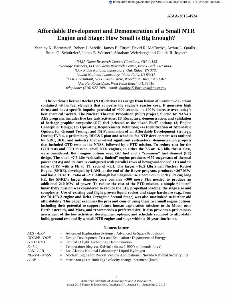
In FY’14, a preliminary DDT&E plan and development schedule was produced by GRC, DOE and industry for
the AES program. It included foundational technology development and significant system-level demonstration
projects involving GTD tests at the NNSS, followed by a FTD mission. Some key activities from the schedule / plan
are shown below in Fig. 1.
R
AIAA-2015-4524
3 American Institute of Aeronautics and Astronautics
Space 2015 Forum & Exposition, Pasadena, CA, August 31 - September 2, 2015
Figure 1. Notional NTP Development Schedule Includes Foundational Technology Development,
Followed by System-Level Ground and Flight Technology Demonstrations
The Foundational Technology Development component of the schedule includes “State-of-the-Art” (SOTA)
reactor/engine modeling, conceptual design and operational requirements definition, along with planning and
schedule development discussed in this paper. As mentioned above, NTP technology development is primarily
focused on demonstrating the viability and performance of GC fuel through “separate effects” tests involving
NTREES and irradiation testing followed by post-irradiation examination (PIE) and evaluation. Last, but not least in
order of importance, is an assessment of candidate ground test facility (GTF) options and the selection of a primary
approach. Subscale validation testing would demonstrate the concept, provide data for benchmarking codes, and
help anchor GTF planning and preliminary design activities. Final GTF design, construction, startup and checkout
would occur during the Ground and Flight Technology Demonstration portion of the development schedule.
In order to reduce development time and cost, the GTD tests and the FTD mission will use a small, low thrust
engines (in either the ~7.5 or 16.5 klbf thrust class) that has a common fuel element design. This approach is
attractive because it allows scalability to higher thrust engines, if and when required, by increasing the number of
elements and the reactor core diameter so that it has a greater thermal power output. A small NTP ground test engine
should also easier to transport, assemble and disassemble after testing has been completed. As currently envisioned,
the GTD project would build and test 1-2 ground test articles (GTA1, GTA2) and one flight test article (FTA) that
provides system technology demonstration and design validation for the follow-on FTD mission.
The FTD mission chosen is a simple “1-burn” lunar flyby mission selected to minimize the engine burn duration,
the LH2 propellant loading, stage size and complexity. The demonstration stage also maximizes the use of existing
and flight proven liquid rocket and stage components to further ensure affordability.
This paper examines the pros and cons of using these two small engine options, including their potential to support
future human missions, and then recommends a preferred size. It also provides a preliminary NASA, DOE and
industry assessment of the key activities, development options, and schedule required to affordably build, ground
test and fly a small NTR engine and stage within a 10-year timeframe. It ends with a summary of our findings and
some concluding remarks.
SOTA Reactor Core
& Engine Modeling
Cermet Fuel
NERVA
Composite
Fuel
Fuel-Rich Engine
SAFE Ground Test Option at the
Nevada National Security Site
Fuel Element
Irradiation Testing
in ATR at INL
NTR Element Environmental
Simulator (NTREES)
Small NTP Stage for
Lunar Flyby Mission
Notional
7.5 or 16.7 klbf
SNTR for FTD?

AIAA-2015-4524
4 American Institute of Aeronautics and Astronautics
Space 2015 Forum & Exposition, Pasadena, CA, August 31 - September 2, 2015
II. NTR Engine Description and Demonstrated Technology
The NTR uses a compact fission reactor core containing 93% “enriched” uranium (U)-235 fuel to generate 100’s
of megawatts of thermal power (MWt) required to heat the LH2 propellant to high exhaust temperatures for rocket
thrust. In an “expander cycle” Rover/NERVA-type engine (Fig. 2), high pressure LH2 flowing from either a single or
twin turbopump assembly (TPA) is split into two paths with the first cooling the engine’s nozzle, pressure vessel,
neutron reflector, and control drums, and the second path cooling the engine’s core support tie-tube assemblies. The
flows are then merged and the heated H2 gas is used to drive the TPAs. The hydrogen turbine exhaust is then routed
back into the reactor pressure vessel and through the internal radiation shield and upper core support plate before
entering the coolant channels in the reactor’s GC fuel elements. Here it absorbs energy produced from the fission of
U-235 atoms, is superheated to high exhaust temperatures (Tex ~2550 – 2950 K depending on uranium fuel loading),
then expanded out a high area ratio nozzle (~300:1) for thrust generation.
Figure 2. Schematic of “Expander Cycle” NTR Engine with Dual LH2 Turbopumps
Controlling the NTR during its various operational phases (startup, full thrust and shutdown) is accomplished by
matching the TPA-supplied LH2 flow to the reactor power level. Multiple control drums, located in the reflector
region surrounding the reactor core, regulate the neutron population and reactor power level over the NTR’s
operational lifetime. The internal neutron and gamma radiation shield, located within the engine’s pressure vessel,
contains its own interior coolant channels. It is placed between the reactor core and key engine components to
prevent excessive radiation heating and material damage.
The fuel elements tested in the Rover / NERVA programs [4] were fabricated using a “graphite matrix” material
that contained the U-235 fuel in the form of either coated particles of uranium carbide (UC2) or as a dispersion of
uranium and zirconium carbide (UC-ZrC) referred to as “composite” fuel. The higher performance GC fuel was
developed as a “drop-in replacement” for the coated particle fuel and was tested in the Nuclear Furnace element test
reactor (NF-1) [4] toward the end of the Rover program. The GC elements were successfully tested for ~2 hours at
peak power densities of ~5 MWt per liter (~5000 MWt/m3) and achieved peak fuel and hydrogen exhaust
temperatures of Tpeak ~2700 K and Tex ~2450 K, respectively. The GC elements also demonstrated better corrosion
resistance than the standard coated particle graphite matrix fuel element used in the previous Rover/NERVA reactor
tests. Composite fuel’s improved corrosion resistance is attributed to its higher coefficient of thermal expansion
(CTE) that more closely matches that of the protective ZrC coating, thereby helping to reduce coating cracking.
Electrical-heated composite fuel elements were also tested by Westinghouse in hot hydrogen at 2700 K for ~600
minutes – equivalent to ten 1-hour cycles. At the end of Rover/NERVA program, composite fuel performance
projections [5] were estimated at ~2-6 hours at full power for hydrogen exhaust temperatures of ~2500-2800 K.
Heritage Rover/NERVA fuel elements had a hexagonal cross section (~0.75 inch across the flats) and 19 axial
coolant channels that were CVD-coated with niobium carbide (NbC) initially, then with ZrC to reduce coating
cracking, hydrogen penetration and subsequent erosion of the graphite matrix material. Individual elements were
1.32 m (52 inches) in length and produced ~1 MWt during steady state, full power operation.
In addition to the FEs, later Rover/NERVA reactor cores used improved hexagonal-shaped tie tube (TT) elements
in place of the earlier tie rods to provide axial structural support to the adjacent FEs surrounding them. The tie rods
and TTs were both attached to an aluminum support plate located at the cold end of the reactor. Unlike the single
pass tie rods that discharged their hydrogen coolant directly into the core exit chamber, the two-pass regenerative
AIAA-2015-4524
5 American Institute of Aeronautics and Astronautics
Space 2015 Forum & Exposition, Pasadena, CA, August 31 - September 2, 2015
cooled TTs had a coaxial Inconel tube to carry the hydrogen coolant that was discharged into the core inlet allowing
further FE heating and significantly raising the engine’s specific impulse. These same TTs are used to supply a
source of heated hydrogen for turbine drive power in the expander cycle engine designs current under study.
A sleeve of zirconium hydride (ZrH) moderator material can also be incorporated in the TTs to help increase core
reactivity and allow construction of smaller size reactor systems like the Rover program’s Pewee engine [4]. Pewee
was designed and built to evaluate higher temperature, longer life fuel elements and improved coatings. It produced
~25 klbf of thrust and set several performance records including the highest fuel element hydrogen exhaust
temperature of ~2550 K, and the highest peak fuel temperature of ~2750 K. Other performance records included
average and peak power densities in the reactor core of ~2340 MWt/m3 and ~5200 MWt/m3, respectively. Improved
ZrC coating was also introduced in Pewee and showed performance superior to the NbC coating used in previous
reactor tests. This same ZrC coating is being applied to the GC fuel elements currently being fabricated at ORNL.
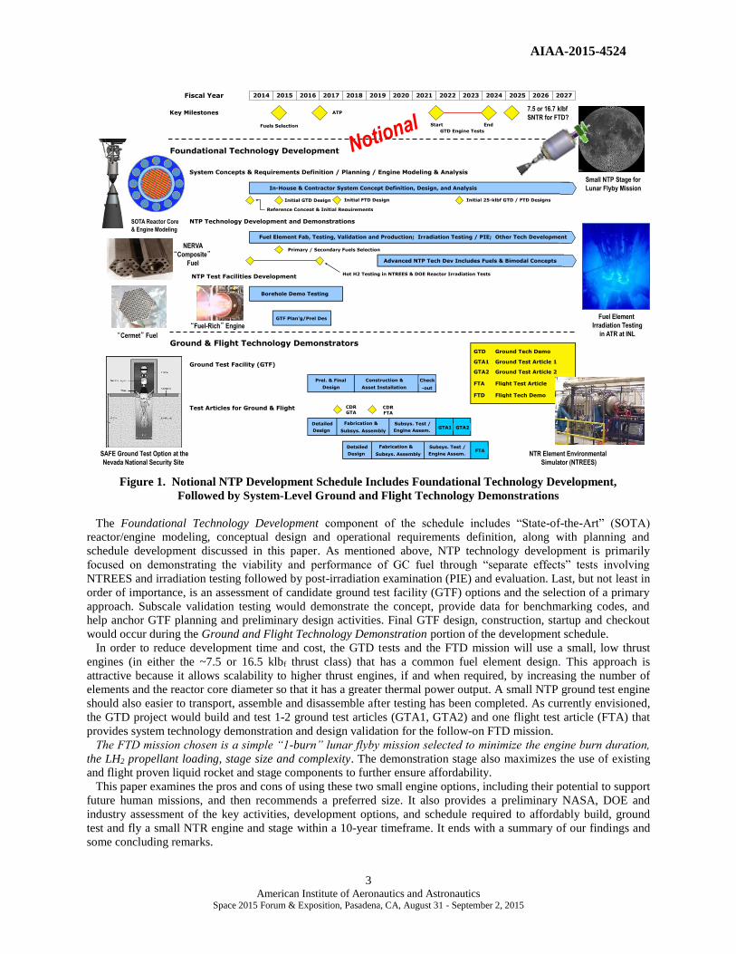
A final reactor design, known as the Small Nuclear Rocket Engine (SNRE) [6], was developed by Los Alamos
National Laboratory (LANL) near the end of the Rover/NERVA program. Although it was not built, it incorporated
lessons learned from Pewee and other reactor designs and test results. The SNRE FE had the same hexagonal cross
section and coolant channel number, but was shorter (0.89 m / 35 inch), and produced ~0.65 MWt. Because it was
smaller than Pewee at ~16.4 klbf of thrust, the SNRE required additional ZrH tie tubes to provide the extra neutron
moderation needed in the engine’s smaller core. In the SNRE core, each FE had 3 TTs and 3 FEs surrounding it
(shown in Fig. 3). It also used GC fuel elements (with ~35 volume % UC-ZrC content) and an expander cycle with
the turbine drive power provided solely by TT hydrogen discharge. The SNRE is the larger of the two small engine
designs that were considered for ground and flight technology demonstration in this preliminary assessment.
Figure 3. Coated Particle and Composite SNRE Fuel Element and Tie Tube Arrangement
Regarding demonstrated technology, NTP has a proven track record plus a specific impulse potential 100% higher
than today’s best chemical rockets. During the Rover/NERVA programs (1955-1972), a technology readiness level
(TRL) of ~5-6 was achieved. Twenty rocket reactors were designed, built and ground tested [4] demonstrating: (1) a
wide range of thrust levels (~25, 50, 75 and 250 klbf); (2) high temperature graphite-based coated particle and
composite nuclear fuels; (3) hydrogen exhaust temperatures up to 2550 K (achieved in Pewee); (4) sustained engine
operation (over 62 minutes for a single burn achieved in the NRX-A6); as well as (5) accumulated lifetime at full-
power; and (6) restart capability (>2 hours with 28 startup and shutdown cycles achieved in the NRX-XE
experimental engine) – all the requirements needed for human missions to Mars. Despite these accomplishments, the
Rover/NERVA program was cancelled in January 1973 without a flight demonstration. Today, NASA is providing

AIAA-2015-4524
6 American Institute of Aeronautics and Astronautics
Space 2015 Forum & Exposition, Pasadena, CA, August 31 - September 2, 2015
modest funding for a small but focused technology development and demonstration effort that it hopes will lead to
the successful ground testing and eventual flight of a small NTR engine.
III. Recent Reactor / Engine Modeling and Conceptual Design Activities
Candidate “Heritage” Fuel Element Designs
In the Rover program, a common fuel element / tie tube design was developed and used to construct a wide range
of different thrust engines. This included the 50 klbf Kiwi-B4E (1964), the 75 klbf Phoebus-1B (1967), the 250 klbf
Phoebus-2A (June 1968), then less than six months later, the 25 klbf Pewee engine (Nov-Dec 1968). This same
approach but in reverse is being followed by the NTP project – design, build, ground test, then fly a small NTR
engine first, then scale it up in size to the larger 25 klbf “Pewee-class” engines featured in NASA’s Mars Design
Reference Architecture (DRA) 5.0 study [7, 8].
During Phase 1 of the NCPS project, “Point-of-Departure” (POD) engine designs for both a small “criticality-
limited” and full size (25 klbf class) engine were developed for both fuel types using the heritage fuel element
designs shown in Fig. 4. For the GC fuel, the well-established 19-hole hexagonal FE and TT geometry from the
Rover/NERVA program was baselined. Ceramic-metal or “cermet” fuel, composed of uranium dioxide (UO2) in a
tungsten (W) metal matrix material, was also developed during the 1960’s to early 1970’s by General Electric (GE)
and Argonne National Laboratory (ANL) as a backup to the Rover/NERVA fuel. Several conceptual reactor/engine
designs were generated by the GE-710 Program [9] and the ANL Nuclear Rocket Program [10]. The GE-710
element was designed for use in higher thrust engines and in general did not scale down well to lower thrust levels.
The reverse is true for the ANL-200 element. It was designed for a low thrust engine but did not scale up well to
higher power levels. The cermet engine cores also required “seven to ten times more” U-235 fuel than the GC core
for the full size 25 klbf-class engine [1].
Figure 4. Heritage Fuel Element Geometries and Relative Size Comparison
Compared to the graphite-based fuels tested during Rover/NERVA, cermet fuel requires considerably more
research and development time since its compositional makeup and fabrication processes are still not well defined
[1]. Demonstrated operating temperatures and volumetric power densities for cermet fuel samples tested in a reactor
environment (~20 samples in all) were well below that required for a viable NTP system [1]. Lastly, the cermet
engine designs developed by GE and ANL were only conceptual and no NTP cermet reactor has ever been
constructed or tested – a stark contrast to the 20 reactor cores tested with graphite fuel during the Rover/NERVA
program. It is for all these reasons that composite fuel was the logical choice in developing a schedule focused on
ground- and flight-testing a small engine within a 10-year timeframe.

AIAA-2015-4524
7 American Institute of Aeronautics and Astronautics
Space 2015 Forum & Exposition, Pasadena, CA, August 31 - September 2, 2015
Collaborative Modeling Approach
A collaborative integrated reactor/engine modeling effort between GRC and ORNL has been used to develop the
POD designs for both the small “criticality-limited” and full size engine. Both engines used GC fuel and the
established FEs and TTs used in the Rover/NERVA cores. The design and analysis sequence is an iterative one that
includes the following steps: (1) establish a preliminary core configuration that meets the fundamental neutronic
performance requirements of criticality and adequate control swing; (2) estimate the approximate thrust level based
on power density considerations for the particular fuel being analyzed; (3) modify the core configuration to adjust
criticality, control swing, and estimated thrust level of the engine; (4) use the neutron and gamma energy deposition
rates resulting from steps (1-3) as input to a coupled thermal-fluid-structural (TFS) analysis of the GC core’s interior
components, specifically the coupled FE and TT; and (5) once acceptable neutronic and TFS performance is
achieved, perform engine cycle balance analysis and estimate of the engine’s overall size and mass.
This collaborative methodology between GRC and DOE is depicted in Fig. 5 and shows the flow of data between
the different computational tools used in developing the POD designs. These tools include MCNP (Monte Carlo N-
Particle transport code) for reactor neutronics [11], ANSYS for multi-physics analysis [12] and NESS (Nuclear
Engine System Simulation code) for engine cycle balance analysis and mass estimation [13].
Figure 5. Computational Tool Methodology used in Designing Rover/NERVA-derived GC Engines
Criticality-Limited, SNRE and Pewee-class Graphite Composite Engine Designs
For Rover/NERVA-derived engine designs, a variety of different FE – TT arrangements are possible depending on
the desired thrust class of the engine (see Fig. 6). In the larger size engines tested in the Rover program, a “sparse”
FE – TT arrangement was used with each FE having 2 adjacent TTs and 4 adjacent FEs comprising its six
surrounding elements. In this sparse pattern, the FE to TT ratio is ~3 to 1. In the SNRE design, shorter FEs were
used and additional TTs were included in the reactor to increase core reactivity. With the “SNRE” FE – TT pattern
each FE has 3 adjacent TTs and 3 adjacent FEs surrounding it and the FE to TT ratio is ~2 to 1. With this
arrangement, each FE is held in position by the lower support pedestals of three adjacent TTs that provide redundant
mechanical support to the FE. A cutaway view of a FE – TT bundle showing additional detail and the “outer mold
ANSYS Model
FE + TT
Cross Section
And Path
A
B
C
D
A DC
B
1
3
5
4
2
Temperature Distributions at Five Axial Stations(Numbers Indicate Cold to Hot End Stations)
Temperature Distribution Across FE and TT
Performance, Size
& Mass estimation
Nuclear Engine System Simulation
(NESS) code has been upgraded
to use MCNP-generated data
Fuel Element-to-Tie Tube ratio
varies with engine thrust level
MCNP neutronics for
core criticality, detailed
energy deposition,
and control
worth

AIAA-2015-4524
8 American Institute of Aeronautics and Astronautics
Space 2015 Forum & Exposition, Pasadena, CA, August 31 - September 2, 2015
line” of the support pedestal is shown in Fig. 7 [6]. An important feature common to both the sparse and the SNRE
FE – TT patterns is each tie tube provides redundant mechanical support for six adjacent fuel elements.
Figure 6. Possible FE – TT Arrangements for Different Thrust Class GC Engines
Recent MCNP transport modeling of engine reactor
cores by Schnitzler et al., [14,15] has shown that the
SNRE design can be scaled down to even lower thrust
levels (~7.5 klbf) or up to the full size 25 klbf-class
engine. For lower thrust engines with short length
elements, additional reactivity gains can be achieved
by employing an entirely new FE – TT arrangement
identified by Schnitzler as the “dense” element pattern
(shown in Fig. 6) consisting of parallel rows of FEs and
TTs. In this configuration each FE has 4 adjacent TTs
and 2 adjacent FEs surrounding it and the FE to TT
ratio has now decreased to ~1 to 1.
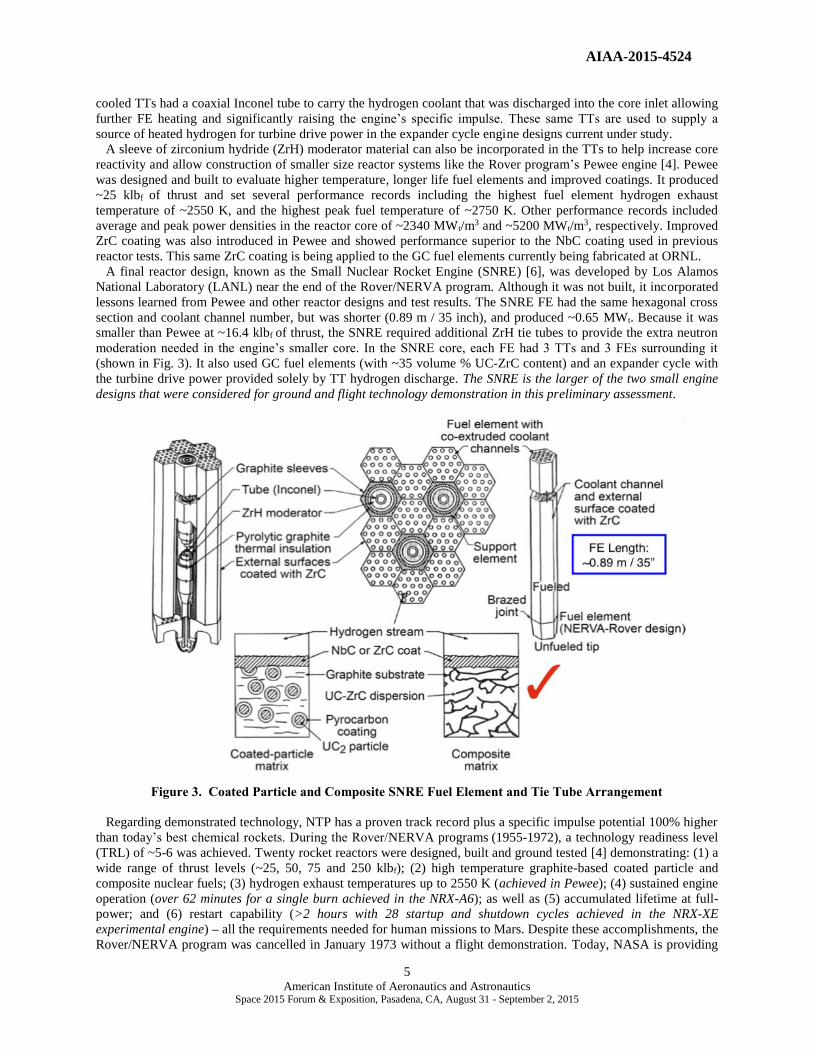
Table 1 summarizes engine and reactor performance
characteristics for several GC engines ranging in size
from a small “criticality-limited” engine to the 25 klbf
“Pewee-class” engine used in Mars DRA 5.0. All the
designs utilize an expander cycle and assume a peak
fuel temperature of ~2860 K and nozzle area ratio
(NAR) of 300:1. The criticality-limited engine has a
thrust of ~7.52 klbf and an engine thrust-to-weight
(T/Weng) ratio of ~1.9. It uses the dense FE – TT
pattern (FE to TT ratio of ~1:1), 35 inch (~89 cm) long
FEs and TTs, and has a fissile fuel loading of ~600 mg
of 93% enriched U-235 per cm3. With a hydrogen flow
rate of ~3.82 kg/s, a chamber pressure of ~565 psia and
a gas temperature exiting the fuel elements (the
chamber inlet temperature) of ~2739 K, the engine’s
specific impulse (Isp) is ~894 s. The maximum fuel
temperature before melting begins is estimated to be
~2900 K for the high fuel loading used in this small
engine so the temperature margin from peak to melt is ~40 K. The total quantity of enriched U-235 fuel in the
engine is ~27.5 kilograms (kg). At ~7.52 klbf thrust, the small engine has a nominal power output of ~157 MWt and
an average power density of ~3.0 MWt per liter. The corresponding peak power density is ~5.37 MWt per liter – just
slightly higher than the ~5 MWt per liter value demonstrated for composite fuel in the Nuclear Furnace. The
engine’s overall length is ~6.19 m, which includes an ~1.26 m long, retractable radiation-cooled nozzle skirt
extension. The corresponding nozzle exit diameter is ~1.38 m.
Fuel Element
TT Support Element
Inner Tie Tube
ZrH Moderator
Outer Tie Tube Insulator
TT Support Pedestal
TT Support End Cap
TT Pedestal Outer Mold
Line
0.8
9 m
Figure 7. SNRE FE – TT Bundle Cutaway Showing
TT Support Pedestal Features and Outer Mold Line
Sparse FE – TT Pattern SNRE FE – TT Pattern Dense FE – TT Pattern
AIAA-2015-4524
9 American Institute of Aeronautics and Astronautics
Space 2015 Forum & Exposition, Pasadena, CA, August 31 - September 2, 2015
Table 1. Performance Characteristics for “Small-to-Full Size” Graphite Composite Engines
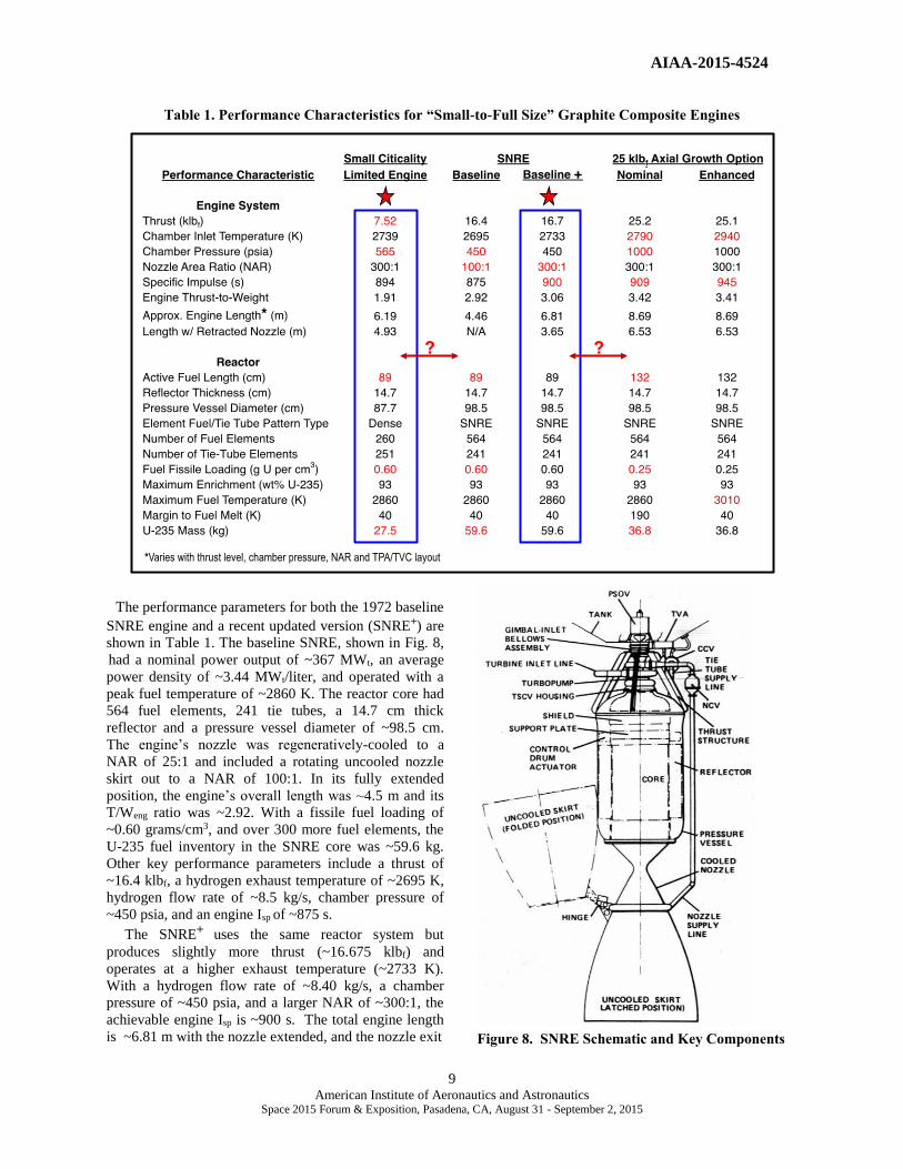
The performance parameters for both the 1972 baseline
SNRE engine and a recent updated version (SNRE+) are
shown in Table 1. The baseline SNRE, shown in Fig. 8,
had a nominal power output of ~367 MWt, an average
power density of ~3.44 MWt/liter, and operated with a
peak fuel temperature of ~2860 K. The reactor core had
564 fuel elements, 241 tie tubes, a 14.7 cm thick
reflector and a pressure vessel diameter of ~98.5 cm.
The engine’s nozzle was regeneratively-cooled to a
NAR of 25:1 and included a rotating uncooled nozzle
skirt out to a NAR of 100:1. In its fully extended
position, the engine’s overall length was ~4.5 m and its
T/Weng ratio was ~2.92. With a fissile fuel loading of
~0.60 grams/cm3, and over 300 more fuel elements, the
U-235 fuel inventory in the SNRE core was ~59.6 kg.
Other key performance parameters include a thrust of
~16.4 klbf, a hydrogen exhaust temperature of ~2695 K,
hydrogen flow rate of ~8.5 kg/s, chamber pressure of
~450 psia, and an engine Isp of ~875 s.
The SNRE+ uses the same reactor system but
produces slightly more thrust (~16.675 klbf) and
operates at a higher exhaust temperature (~2733 K).
With a hydrogen flow rate of ~8.40 kg/s, a chamber
pressure of ~450 psia, and a larger NAR of ~300:1, the
achievable engine Isp is ~900 s. The total engine length
is ~6.81 m with the nozzle extended, and the nozzle exit
Figure 8. SNRE Schematic and Key Components

AIAA-2015-4524
10 American Institute of Aeronautics and Astronautics
Space 2015 Forum & Exposition, Pasadena, CA, August 31 - September 2, 2015
diameter is ~2.26 m. The engine T/Weng is also a little higher at ~3.06.
The performance characteristics for a 25 klbf-class GC engine, similar to that used in NASA’s DRA 5.0, is based
on an “axial-growth” version of the SNRE [14,16]. It uses the same SNRE FE – TT pattern but the FE length is
increased from 0.89 m to 1.32 m (the same length used in the Pewee engine). The engine’s performance parameters
include: Tex ~2790 K, chamber pressure ~1000 psia, hydrogen flow rate ~12.5 kg/s, Isp ~909 s, and T/Weng ~3.42.
The engine has a nominal power output of ~563 MWt and the corresponding average and peak power densities are
~3.36 and 5.70 MWt / liter, respectively. The overall engine length is ~8.69 m, which includes an ~2.16 m long,
retractable radiation-cooled nozzle skirt extension. The corresponding nozzle exit diameter is ~1.89 m. A higher
chamber pressure is used in this design to help maintain reasonable nozzle dimensions at the assumed NAR.
The engine’s reactor core contains 564 FEs and 241 TTs – the same number found in the SNRE. It also has the
same reflector thickness and pressure vessel diameter as the SNRE. With its longer fuel elements and tie tubes,
however, the U-235 fuel loading used in the reactor FEs can be reduced to ~0.25 grams/cm3 thereby lowering the
inventory of 93% enriched U-235 in the core to just under 37 kilograms. Lowering the fuel loading from ~0.60 to
0.25 grams/cm3 also allows the FEs to operate at a higher peak fuel temperature of ~3010 K while still staying
below the melt temperature for composite fuel of ~3050 K. The corresponding increase in the exhaust temperature
to ~2940 K results in an ~35 second increase in Isp to ~940 s if required to help stretch the available LH2 propellant
loading to meet mission requirements, or in the case of an emergency to allow a safe return of the crew.
Between the two small engine options analyzed – the ~7.5 klbf criticality limited engine and the SNRE options –
the SNRE+ configuration is an attractive option for development, ground testing and flight demonstration for the
following reasons: (1) a previously developed program plan for the SNRE already exists [17] and can be used as a
point of comparison; (2) the SNRE FE – TT arrangement has 6 FEs surrounding each of TT so the pedestal
geometry at the bottom of each TT is the same as that used in the larger ~25 klbf-class engine; and (3) both engines
use 35 inch long FEs so the SNRE+ is only ~0.6 m longer than the 7.5 klbf engine despite its higher thrust output. It
can therefore be used for the single engine FTD mission, and with clustered SNRE-class engines can be used for
cargo delivery and crewed lunar landing missions [18], as well as, near Earth asteroid (NEA) missions [19]. Even
human Mars missions appear possible if smaller payload elements are considered along with a reduced crew size as
currently being envisioned in NASA’s “Evolvable Mars Campaign”. This could lead to a “one size fits all”
approach to NTR development using the SNRE-class GC engine.
On the negative size, each SNRE / SNRE+ reactor core has 304 more FEs than the smaller 7.5 klbf engine core
(shown Table 1). Choosing the SNRE / SNRE+ for GTD and FTD will require additional production capacity be
brought on line to fabricate the extra 912 FEs in time to meet the start dates for the GTD tests and the FTD mission.
IV. NTP Technology Development: Recapture, Fabrication and Testing of Composite Fuel
As mentioned in the Introduction, recapturing past fuel processing techniques and demonstrating the ability to
fabricate partial length FEs for testing and performance validation has been the primary focus of the NCPS and
current NTP project. During the Rover/NERVA program, many thousands of high quality, precision-made FEs were
produced at LANL, ORNL’s Y-12 Facility, and the Westinghouse Astronuclear Laboratory (WANL). A wealth of
data was generated on the required processing parameters and specifications, materials of construction, and the
equipment used in fabricating and coating both particle and composite fuel. These results were documented, in great
detail, in reports by Taub [5], Lyon [20] and Davidson [21].
Since 2011, researchers at ORNL have been reviewing the literature, procuring hardware, and assembling the
equipment needed to fabricate and coat heritage GC fuel elements. Lab-scale equipment for FE fabrication is shown
in Fig. 9 [22]. It includes the extruder, dies for producing initial 4-hole test elements and follow-on 19-hole heritage
elements, and an element layout tray. Equipment setup has benefited from past “lessons learned” during the
fabrication of the heavier composite elements. Due to increased friction as the fresh extrusion moved from the die
along the graphite layout tray, the rear portion of the FE tended to compress and bulge so FE dimensions were wider
at the back than in the front. By introducing a series of small air holes in the base of the layout tray – a feature
incorporated in ORNL’s current graphite insert (see Fig. 9) – the GC elements were now able to move on a film of
air minimizing the sliding contact between the element and tray and eliminating fuel element distortion.
Composite fuel elements, consisting of uranium carbide, zirconium carbide and graphite matrix materials, were
produced from a blended mixture of graphite flour, carbon black, ZrC powder, UO2 powder, and thermosetting resin

AIAA-2015-4524
11 American Institute of Aeronautics and Astronautics
Space 2015 Forum & Exposition, Pasadena, CA, August 31 - September 2, 2015
Figure 9. Equipment Assembled at ORNL for Extrusion of Composite Fuel Elements
(binder) using an extrusion process. The extruded fuel elements were then heat treated to form a “web-shaped
dispersion” of solid solution UC-ZrC fuel within the graphite matrix material. In addition to reconstituting lab-scale
fabrication capability, ORNL researchers face another challenge that of duplicating the source materials used to
produce the composite fuel elements successfully tested in the past. Due to the inability to procure exact matches for
these materials, substitutions in the fuel formulation must be made and their impact determined through testing.
Coating is another key technology that underwent significant development during the Rover/NERVA program.
The CVD process became quite sophisticated allowing the nineteen 2.4 mm diameter coolant channels in each FE to
be coated with NbC tailored in thickness from ~50 - 100 m over the full 1.32 m length of the element. The coating
material was later changed to ZrC – the current baseline material – because it better adhered to the graphite and had
more desirable neutronic characteristics and lower fission product diffusion rates.
Key parameters important to the coating process are the optimization and control of the coating temperature and
the reactant species composition as it is flowed through the element. Temperature control was accomplished using a
multi-zone inductively heated furnace with the reactant gas flowing from the “cold to hot” end of the element. In
order to achieve the desired coating properties over the entire FE length, the coating temperature had to be increased
incrementally from the inlet to the exit end of the coating furnace to compensate for the depletion of the reactant gas
as it traveled along the axial length of the fuel element [23,24].
A new “6-zone” CVD coating furnace (with 4 heating coils per zone) has been set up at ORNL (Fig. 10) to
demonstrate the ability to deposit tailored thicknesses of the ZrC coating along the FE length [25]. With improved
fabrication measurement techniques and coating capabilities, better matching of the CTE for the composite fuel and
ZrC coating can hopefully be achieved as compared to what was possible in the 1970s. It is also envisioned that the
use of current day technology, including the use of modern computer controlled temperature sensors and electronic
mass flow controllers, will help improve the CVD coating process so as to further minimize cracking and erosion.

AIAA-2015-4524
12 American Institute of Aeronautics and Astronautics
Space 2015 Forum & Exposition, Pasadena, CA, August 31 - September 2, 2015
Figure 10. ORNL CVD Coating Furnace, Baseline and Alternative Coating Concepts
Additional coating materials and concepts are also being studied and developed at GRC [26] to help prevent or
minimize cracking and could be applied if it persists using the baseline ZrC coating. A new, multilayer metallic
coating architecture has been proposed for application to the “mid-band erosion” area of the FE where cracking was
observed during the Rover/NERVA program. The new coating approach (shown schematically in Fig. 10) uses
graded layers of molybdenum-niobium (Mo-Nb) positioned between the graphite matrix material and the outer ZrC
coating. Its potential advantages are highlighted in Fig. 10. A Mo overlay, effectively used in some Rover/NERVA
engine tests [4], can also be applied to seal any developing cracks in the ZrC and further help reduce H2 permeation.
Lastly, because of its established database, the fuel specifications and production requirements for GC fuel are not
expected to change significantly. As a result the major portion of the development plan for GC fuel will likely focus
on validating new production samples and elements and correlating data on them to historical data to increase
confidence in the fuel’s performance and to reduce programmatic risk.
V. NTP Ground Test Facility (GTF) Options and ConOps
Ground test demonstrations of NTP components, subsystems, and the integrated reactor/engine system are a
necessary precursor to qualifying a system for flight demonstration. In contrast to the “open air” testing conducted
during Rover/NERVA, current environmental protection (NEPA) standards prohibit any significant release of
radioactive particulates into the air from a nuclear test facility. As in the past, the preferred and logical location for
conducting NTR ground tests is the NNSS formerly known as the Nevada Test Site. The Site occupies ~1375 square
miles and provides a large secure safety zone containing valuable on-site assets and a variety of locations well suited
for NTP testing.
The pros and cons for the different ground test options can best be discussed by considering the scope of activities
involved in an overall “Concept of Operations” (ConOps) for testing shown in Fig. 11. Fabricating the required
number of precision fuel elements containing highly enriched U-235 (HEU) will be done at either ORNL’s Y-12
Facility or by an industry contractor team responsible for building the reactor and engine system. Building up the
reactor subsystem will involve integrating the core assembly with its peripheral reflector and control drums and its
Advantages of Multilayer Coating Approach:
• Minimizes ZrC/(U,Zr)C-graphite matrix CTE differences.
• Ductile compliant metallic layers will accommodate
residual stresses.
• Mo overlay seals cracks in the ZrC coating and
reduces H2 permeation.
• Mo-Nb layers expected to reduce H 2 permeation.
• Mo2C expected to be a diffusion barrier for carbon.
Multilayer Metallic Coating Concept ORNL 6-zone CVD Coating Furnace
Coolant
Channel
Area
FE Matrix
Material
Area
ZrC Coating
Single Layer ZrC Coating is Baseline

AIAA-2015-4524
13 American Institute of Aeronautics and Astronautics
Space 2015 Forum & Exposition, Pasadena, CA, August 31 - September 2, 2015
placement within the reactor pressure vessel. The hydrogen turbopump assembly, exhaust chamber and truncated
regenerative-cooled nozzle will then be added to the pressure vessel to complete the engine assembly.
This buildup process will likely be performed at the Device Assembly Facility (DAF) located within the NNSS.
The DAF is a state-of-the-art facility that includes a collection of steel-reinforced concrete test cells connected by a
rectangular corridor. The entire complex is covered by compacted earth and spans an area of ~100,000 square feet
(the size of ~11 football fields). The DAF has multiple assembly/test cells designed to handle special nuclear
materials, plus high bays with multi-ton crane capability sufficient to handle the small engine sizes currently being
considered. It is envisioned that the DAF will be used as a pre-test staging area for component aggregation, engine
assembly and “0-power” critical testing prior to being transported to the chosen test location.
Figure 11. Possible Concepts of Operation for NTP Ground Testing
With the potential for radioactive effluent release to the atmosphere with open air testing, future test methods will
require that the engine exhaust be scrubbed to remove any radioactive contaminants. This can be accomplished in
one of two ways. The first option is to develop an above ground effluent treatment system (ETS) that would be
attached to the engine’s nozzle and used to scrub and filter the hydrogen exhaust of any radioactive particulates and
low-level fission product gases. The hydrogen-rich filtered exhaust would then be burned off in a flare stack. The
design and technical feasibility of this type of ETS was successfully demonstrated on the NF-1 fuel element test
reactor [4] at the end of the Rover/NERVA program. Operating at ~44 MW t, NF-1 represents an ~1/4th - 1/10th scale
demonstration of the ETS that would be needed to test the 7.5 klbf and SNRE-class engines being considered here.
Another above ground option, referred to as “full-containment” [27], burns the hydrogen exhaust with additional
oxygen to create oxygen-rich steam that is then cooled by heat exchangers, converted to water, and collected in large
storage tanks. Filters and particle traps positioned along the exhaust stream remove the radioactive contaminants
while the stored water is slowly filtered into retention ponds where it subsequently evaporates.
Both of the above options scale in size with engine thrust level and hydrogen throughput and can therefore become
quite large and complex increasing the time and cost to build them. The second approach capitalizes on the existing
geology and infrastructure at three different locations at the NNSS (included in Fig. 9) to help simplify and lower
the cost of ground testing. The three sites include: (1) several deep (~1200 ft), large diameter (~8 ft) vertical holes
dug previously for underground nuclear weapons testing; (2) the underground U1a complex; and (3) the P-tunnel
complex located inside the Rainier Mesa.
In the SAFE (Subsurface Active Filtration of Exhaust) concept originally proposed by Howe et al., [26], the
vertical boreholes and the natural geology of the soil (alluvium) are exploited to provide “in-situ” capture, holdup
and subsequent filtration of the engine exhaust. Conceptually simple, the engine is enclosed within a steel
containment structure attached to a concrete slab surrounding the top of the borehole. A seal around the nozzle
throat extends down to the top of the hole to prevent exhaust gas release to the surface. As the engine fires down into
the hole, a water or liquid nitrogen spray cools and condenses the exhaust. The pressure builds and eventually
reaches a level where the amount of gas and water vapor driven into the porous soil and rock equals the mass flow
DAF - Device Assembly Facility PIE - Post Irradiation Examination
Fuel Element Fabrication
Core Assembly
Engine Assembly
P Tunnel
Industry
ORNL / Y-12
Reactor Assembly
Engine Ground Testing
Borehole
Disposal / HEU Recovery
@INL following
PIE
Control / Data Acquisition,
H2 Supply
Nozzle, Pump, H2 Feed Lines
Non-nuclear Components
U1a Tunnel
Pressure Vessel, Reactor Control
Disassembly and PIE
@NNSS entomb
in tunnel
Limited FE and components
shipment to INL for PIE
DAF @NNSS
DAF @NNSS
DAF @NNSS
FE, components extraction at
test site using Portable Hot Cell

AIAA-2015-4524
14 American Institute of Aeronautics and Astronautics
Space 2015 Forum & Exposition, Pasadena, CA, August 31 - September 2, 2015
of the engine. There is no costly fixed infrastructure. Mobile trailers are used for control and data acquisition and
tank cars supply the hydrogen propellant and water used during the test. Recent analysis of the SAFE concept and
the design for a small, non-nuclear, subscale validation test of concept feasibility are reported on elsewhere [3, 29].
A disadvantage of the borehole approach is its “above ground” location that will require increased cost to maintain
a secured perimeter around the site. These increased security measures are needed to protect the HEU contained
within the engine and to restrict and/or limit access to the site during engine operation, the post-test cool down
period, and the subsequent disassembly phase as outlined in Fig. 11. It is envisioned that a “mobile hot cell” unit
would be used to disassemble and remove an initial sampling of FEs and reactor components from the engine’s
reactor core for shipment to INL for PIE. The unit would be similar to that shown in Fig. 12 and developed with
IAEA (International Atomic Energy Agency) funding for the recovery and packaging of Spent High Activity
Radioactive Sources (SHARS) [30].
Figure 12. SHARS Mobile Hot Cell Unit with Interior Remote Manipulator Arms
Over time all of the fuel elements would be removed and transported to INL using existing shipping containers for
HEU recovery before disposal since very little fuel will be consumed during engine testing. Other reactor and engine
components can be shipped to INL for evaluation and disposal as well, or disposal at an appropriate NNSS location
may be possible. The NNSS has two other “less accessible” locations that can help lower the security requirements
and cost to test there. At both locations, long, large diameter horizontal tunnels would be used for engine testing.
The expansive U1a complex is located ~1000 feet below the surface and contains a series of interconnected
tunnels used in conducting subcritical tests. For use in NTP testing, a new dedicated tunnel would need to be
excavated to accommodate the expected NTP test conditions. To run the test, hydrogen would be supplied from the
surface using double-walled piping and a water supply would cool and condense the engine exhaust before it
penetrates the surrounding porous alluvium soil. A nearby parallel drift would accommodate a portable SHARS-like
hot cell unit for post-test engine disassembly, FE and component removal and packaging, then transport to the
surface and on to INL for PIE and disposal.
Tunnel testing deep underground can also provide an added measure of safety. Should a serious accident occur
causing a significant release of fissile material, or conditions preventing safe access to the engine for test personnel,
a large “quick closing valve” can be activated to entomb the disabled engine in place by sealing off the test tunnel
from the rest of the complex. Entombment within the tunnel may also be a final disposal option if it is determined
that the time and cost to ship the engine’s components to INL for HEU recovery and disposal are prohibitive.
Using the P-tunnel complex for NTP testing appears to be a viable option based on preliminary analysis [27]. In
contrast to the boreholes and U1a tunnels dug primarily in alluvium soil, the P-tunnel walls are composed mostly of
rhyolite, an extrusive igneous rock containing ~70% SiO2. During NTR testing, these rock walls can provide a large
surface area for heat dissipation reducing the need for water spray cooling. A heat exchanger can be used to
condense the exhaust and reduce pressure buildup, and a nitrogen-cooled, charcoal filter can be used to remove any
low-level fission product gases that might escape the fuel elements and enter the engine’s hydrogen exhaust stream.
A flare stack positioned at the end of the tunnel and exiting to the surface would burn off excess hydrogen to further
regulate the tunnel pressure during the test. Radiation detectors would also be used to measure radionuclide
emissions within the tunnel and in the case of a significant release from failed fuel would activate a “quick closing
valve” to seal off the flare stack and prevent any release to the atmosphere.
From a security and operational standpoint, testing in the P-tunnel complex is an attractive option because it
has more direct access, only one entry portal to protect, and the surrounding Mesa prevents any other access to the
tunnel and its interior assets. The complex is also less developed and utilized than U1a so the additional security
measures that would be required for NTP testing will have less impact than if testing were to be conducted at U1a.
Lastly, the tunnel already exists so the cost of digging a new one is eliminated.

AIAA-2015-4524
15 American Institute of Aeronautics and Astronautics
Space 2015 Forum & Exposition, Pasadena, CA, August 31 - September 2, 2015
VI. Candidate FTD Mission: A “Single-Burn Lunar Flyby”
To reduce the cost of the FTD mission, a simple “1-burn” lunar flyby mission is assumed. The small NTP stage
(SNTPS) also maximizes the use of existing flight proven liquid rocket and stage components to further ensure
affordability. The flight stage shown below in Figs. 13 uses the small criticality-limited 7.5 klbf engine discussed in
Section II. Its key features and performance characteristics are provided in Table 1 and a layout of the engine with
dimensions is shown below in Fig. 13. The engine uses an RL10-class LH2 turbopump and a lightweight radiation-
cooled, retractable composite skirt like that used on the RL10B-2 engine (shown below in Fig. 14) [31, 32].
Figure 13. Engine Layout / Features for Small 7.5 klbf NTR Engine and Stage
The thrust chamber and nozzle are regeneratively-cooled to an
area ratio of 25:1 in keeping with the SNRE design. The nozzle
then continues using a radiation-cooled carbon composite nozzle
extension. As shown in Fig. 8, the original SNRE design used an
uncooled nozzle extension to an area ratio of 100:1 that folded
about a hinge located at the edge of the nozzle circumference [6].
In the engine designs presented here, a nozzle area ratio of 300:1 is
used to increase Isp to ~900 s. In an effort to reduce the engine’s
overall length to accommodate a small mission payload and the
stage’s LH2 tank within the launch vehicle’s payload fairing, the
designs presented in this paper utilize an RL10B-2 style nozzle
deployment mechanism. This mechanism allows a sizeable portion
of the uncooled nozzle extension to retract over the engine’s
regeneratively-cooled thrust chamber, nozzle, and power head
assembly (shown in Fig. 14), thus effectively reducing the engine’s
stowed length by ~50%. The deployment mechanism consists of a
support structure, control electronics, a drive motor, and a set of Figure 14. RL10B-2 engine with
retracted nozzle extension
Retractable Radiation-cooled
Section 49.6 (in)
126 (cm)
Core Length
35 (in) 88.9 (cm)
Core
Regenerative and
Radiation-cooled Nozzle
RL10 Fuel Turbopump
PV Dia. 34.5 (in)
87.7 (cm)
Exit Dia. 52.1 (in)
132.3 (cm)
Retracted Length
194.1 (in) 493 (cm)
Total Length
243.7 (in) 619 (cm)
Retracted
Length
194.1 in
493 cm
AIAA-2015-4524
16 American Institute of Aeronautics and Astronautics
Space 2015 Forum & Exposition, Pasadena, CA, August 31 - September 2, 2015
belt driven ball screw actuators that axially translate the nozzle skirt downward from its stowed position to its
deployed position [33, 34]. When retracted, the small engine (minus the forward radiation shield) has approximately
the same length as the RL10B-2 engine used on the Delta Cryogenic Second Stage (DCSS) [31]. The SNTPS uses the same LH2 tank as that used on the DCSS so it has the same outer diameter but has a shorter
overall length as shown in Fig. 13. An additional barrel section can be added to the LH2 tank to accommodate more
propellant for higher energy missions [31]. The SNTPS also utilizes other flight proven stage components found on
the DCSS (e.g., systems for pressurization, attitude control, avionics and power, plus interstage and thrust structure).
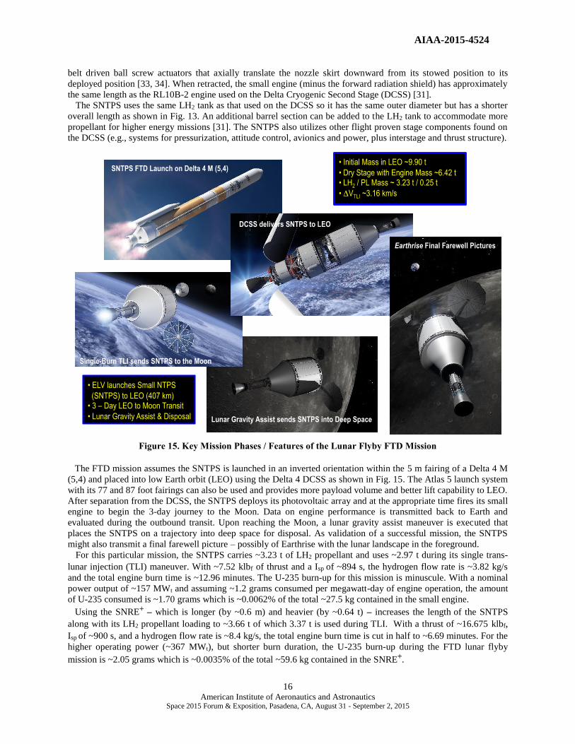
Figure 15. Key Mission Phases / Features of the Lunar Flyby FTD Mission
The FTD mission assumes the SNTPS is launched in an inverted orientation within the 5 m fairing of a Delta 4 M
(5,4) and placed into low Earth orbit (LEO) using the Delta 4 DCSS as shown in Fig. 15. The Atlas 5 launch system
with its 77 and 87 foot fairings can also be used and provides more payload volume and better lift capability to LEO.
After separation from the DCSS, the SNTPS deploys its photovoltaic array and at the appropriate time fires its small
engine to begin the 3-day journey to the Moon. Data on engine performance is transmitted back to Earth and
evaluated during the outbound transit. Upon reaching the Moon, a lunar gravity assist maneuver is executed that
places the SNTPS on a trajectory into deep space for disposal. As validation of a successful mission, the SNTPS
might also transmit a final farewell picture – possibly of Earthrise with the lunar landscape in the foreground. For this particular mission, the SNTPS carries ~3.23 t of LH2 propellant and uses ~2.97 t during its single trans-
lunar injection (TLI) maneuver. With ~7.52 klbf of thrust and a Isp of ~894 s, the hydrogen flow rate is ~3.82 kg/s
and the total engine burn time is ~12.96 minutes. The U-235 burn-up for this mission is minuscule. With a nominal
power output of ~157 MWt and assuming ~1.2 grams consumed per megawatt-day of engine operation, the amount
of U-235 consumed is ~1.70 grams which is ~0.0062% of the total ~27.5 kg contained in the small engine.
Using the SNRE+ – which is longer (by ~0.6 m) and heavier (by ~0.64 t) – increases the length of the SNTPS
along with its LH2 propellant loading to ~3.66 t of which 3.37 t is used during TLI. With a thrust of ~16.675 klbf,
Isp of ~900 s, and a hydrogen flow rate is ~8.4 kg/s, the total engine burn time is cut in half to ~6.69 minutes. For the
higher operating power (~367 MWt), but shorter burn duration, the U-235 burn-up during the FTD lunar flyby
mission is ~2.05 grams which is ~0.0035% of the total ~59.6 kg contained in the SNRE+.

AIAA-2015-4524
17 American Institute of Aeronautics and Astronautics
Space 2015 Forum & Exposition, Pasadena, CA, August 31 - September 2, 2015
VII. Applicability of “SNRE+-class” Engine for Future NASA Human Exploration Missions
While the 7.5 klbf engine is sufficient for the FTD mission and a variety of robotic science missions [31, 35], the
higher thrust ~16.7 klbf SNRE+-class engine is better suited to support future human exploration missions. Using a
common NTP stage (NTPS) with a 3-engine cluster of SNRE+ engines, along with a supplemental in-line LH2 tank,
year-long round trip near Earth asteroid (NEA) missions [19], lunar cargo and crewed lunar landing missions [18],
and even human Mars missions are possible assuming smaller individual payload elements and crew size as
currently envisioned in NASA’s Evolvable Mars Campaign (EMC). A brief discussion of these candidate missions
along with the associated vehicle features and operational requirements on the SNRE+ engines is provided below.
Reusable Crewed Mission to NEA 2000 SG344
Crewed NEA missions have been studied previously by NASA as attractive precursors for demonstrating key in-
space exploration technologies and capabilities (e.g., reliable life support systems, long duration habitation and
cryogenic fluids management, and advanced propulsion) required for traveling through and living in deep space. In
addition to the scientific knowledge gained by an “up close and personal” examination of these primordial objects,
NEA missions can also provide a proving ground for validating the spacecraft systems that will be needed before
sending astronauts to Mars.
The small NEA, 2000 SG344, is an example of low energy target. It has a 2028 launch date and a round trip time
of ~327 days that includes a 7-day stay time. Specific mission V budget details include trans-NEA injection (TNI)
VTNI ~3.254 km/s, braking upon arrival VArrival ~0.144 km/s, trans-Earth injection (TEI) VTEI ~0.392 km/s and
Earth orbit capture (EOC) VEOC ~1.203 km/s (into an assumed 500 km perigee x 20,238 km apogee 6-hr elliptical
Earth orbit (EEO) with an arrival Vinf at Earth of ~0.855 km/s).
Key features of the nuclear-powered Asteroid Survey Vehicle (ASVN) developed for this mission are shown in
Fig. 16. Called “Search Lite”, it is a zero-gravity (0-gE) in-line vehicle that uses autonomous rendezvous and
docking (R&D) for assembly and has three key elements: (1) the “core” NTPS; (2) an integrated “saddle truss” and
LH2 drop tank assembly; and (3) the crewed NEA payload (PL) element. The latter includes the Orion Multi-
Purpose Crew Vehicle (MPCV), a TransHab module outfitted for 4 crew, deployable rectangular photovoltaic arrays
(PVAs) used for primary power, a 2-person Multi-Mission Space Exploration Vehicle (MMSEV) used for close-up
inspection and sample gathering, and a short saddle truss connecting the payload element to the rest of the ASVN.
The MMSEV is attached to the TransHab via a short transfer tunnel that also contains a secondary docking port.
Figure 16. “Search Lite” ASVN used in Reusable Crewed Mission to NEA 2000 SG344
Search Lite’s NTPS uses a three-engine cluster of SNRE+ engines and carries external radiation shield mass on
each engine for additional crew protection. The NTPS uses a 7.6 m diameter aluminum-lithium (Al/Li) LH2 tank and
housed within its forward cylindrical adaptor section are the reaction control system (RCS), avionics, batteries,

AIAA-2015-4524
18 American Institute of Aeronautics and Astronautics
Space 2015 Forum & Exposition, Pasadena, CA, August 31 - September 2, 2015
deployable twin Orion-type circular PVAs, and docking system, along with a reverse turbo-Brayton cryocooler
system for zero boil-off (ZBO) LH2 storage. The Brayton cryocooler system mass and power requirements increase
with tank diameter and are sized to remove ~42 watts of heat penetrating the 60 layer MLI system while the stage is
in LEO where the highest tank heat flux occurs. To remove this heat load, the 2-stage cryocooler system requires
~5.3 kWe for operation. Twin circular PVAs on the propulsion stage provide the electrical power for the ZBO
system in LEO until the primary PVAs on the crewed PL section are deployed prior to TNI.
Individual vehicle components for Search Lite are limited to 70 t and it is assumed that three “upgraded” SLS-1B
launches, each with a capable expendable upper stage, are available to deliver them to the 407 km LEO assembly
altitude. The vehicle’s initial mass in LEO (IMLEO) is ~184.6 t which includes the NTPS (~70 t), the saddle truss
and drop tank assembly (~59.2 t) and the PL section (~55.4 t). The overall vehicle length is ~78.3 m including the
8.9 m long Orion MPCV. The long and short saddle truss segments connecting the vehicle elements together are a
composite structure whose mass scales with tank diameter and length.
The LH2 tank lengths and propellant loadings are ~15.7 m and ~39.7 t for the NTPS, and ~16.7 m and ~42.6 t for
the drop tank. The NTPS used on Search Lite is the same as that used on the reusable, lunar cargo delivery and
crewed landing missions discussed below. It is the crewed mission application that actually determines the NTPS’s
physical dimensions and characteristics. Maximizing the use of common hardware elements (e.g., same size NTPS,
propellant tanks) for different mission applications has been an important consideration emphasized here to help
reduce vehicle development and recurring costs.
The reusable crewed mission to 2000 SG344 requires 5 primary burns (4 restarts) that use ~76.2 t of LH2
propellant. With ~50 klbf of total thrust and a Isp of ~900 s, the total engine burn time is ~50.4 minutes. The first of
the two TNI perigee burns is the longest single burn at ~27.4 minutes after which the vehicle’s drop tank is drained
and jettisoned. The NTPS provides the LH2 propellant needed for the remaining propulsive maneuvers: the second
perigee burn (~9.7 minutes), braking at 2000 SG344 (~1.2 minutes), TEI (~3.1 minutes), and EOC (~9.0 minutes).
With the vehicle’s available propellant capacity, it is also capable of capturing into a lower apogee, higher energy
6-hr EEO at the end of the mission. For this round trip mission, the U-235 burn-up in each engine is ~15.4 grams
which is less than 0.026% of the total ~59.6 kg contained in the SNRE+.
Reusable Lunar Cargo Delivery Mission
Nuclear thermal propulsion can also play an important role in returning humans to the Moon by providing an
affordable in-space lunar transportation system (LTS) with reuse capability that could allow initial lunar outposts to
evolve into eventual settlements capable of supporting commercial activities. The NTPS is the “workhorse” element
of the LTS [18] and has the same features and characteristics as that used on Search Lite. The second major element
is an “in-line” Al/Li propellant tank that connects the NTPS to the forward PL element. It has the same 7.6 m
diameter and supplies the LH2 propellant needed for the “2-perigee burn” TLI maneuver. Depending on the mission
and the PL carried, the tank length can vary from ~15.7 m (same length as in the NTPS) to ~18.7 m and capable of
holding ~49.0 t of LH2 propellant. The in-line tank element also includes forward and aft cylindrical adaptor
sections that house quick connect/disconnect propellant feed lines, electrical connections, a RCS along with docking
and payload adaptors. A ZBO cryocooler system is not used on the in-line LH2 tank since it is drained during the
TLI maneuver. The total length of the in-line element varies from ~20.7 to 23.7 meters.
On cargo flights, the lunar NTR (LNTR) transport can deliver an ~60 t integrated habitat lander with surface
mobility to low lunar orbit (LLO) then return to Earth for refueling and reuse. Three SLS-1B launches are again
used to deliver the vehicle and payload elements to LEO for assembly via autonomous R&D. The LNTR cargo
transport then departs from LEO (C3 ~ -1.678 km2/s2, VTLI ~3.214 km/s including a g-loss of ~117 m/s) and
captures into a 300 km circular LLO (arrival C3 ~1.151 km2/s2 and VLOC ~906 m/s including g-loss) approximately
72 hours later. Key phases of the cargo delivery mission are illustrated in Fig. 17.
Once in orbit, the habitat lander separates from the LNTR transport and descends to the surface, landing
autonomously at a predetermined location on the Moon. It is assumed that the habitat landers use LOX/LH2
chemical engines and are also equipped with either deployable wheels (shown in Fig. 17) or articulated landing gear
allowing movement in both the vertical and horizontal directions so that the landers can either “drive or walk” short
distances from the landing site. Connecting several “functionally different” lander modules together (for habitation,
science, equipment servicing) would form a large contiguous pressurized volume for the crew and also provide a
“building block” approach to establishing an initial lunar base.
After payload separation and a day in LLO, the LNTR cargo transport performs a TEI burn (C3 ~ 0.945 km2/s2,
VTEI ~857 m/s including g-loss) and returns to Earth 72 hours later. On final approach, it performs a braking burn

AIAA-2015-4524
19 American Institute of Aeronautics and Astronautics
Space 2015 Forum & Exposition, Pasadena, CA, August 31 - September 2, 2015
Figure 17. Reusable NTP Lunar Cargo Delivery Mission Phases
(arrival C3 ~ -1.755 km2/s2, VEOC ~366 m/s) and captures into a 24-hour EEO with a 500 km perigee x 71,136 km
apogee. Post burn engine cool-down thrust is then used to assist in orbit lowering. An auxiliary tanker vehicle,
operating from a LEO servicing node/propellant depot, supplies the additional LH2 propellant to the cargo transport
for final orbit lowering and rendezvous with the LEO transportation node where it is refurbished and resupplied
before its next mission.
The LNTR cargo transport shown in Fig. 17 has an IMLEO of ~186.7 t consisting of the NTPS (~70 t), the in-line
tank element (~52.6 t), and the habitat lander (~61.1 t) with its connecting structure (~3.0 t). The overall vehicle
length is ~60.4 m. The cargo transport also uses ~15.7 m long tanks in both the NTPS and in-line element with each
tank carrying ~39.7 t of LH2 propellant. By using clustered SNRE+ engines and maximizing the use of common
hardware elements (e.g., same size NTPS, propellant tanks) for a variety of mission applications it should be
possible to reduce vehicle development and recurring costs while also improving the overall LTS affordability.
For the reusable cargo delivery mission, 5 primary burns by the SNRE+ engines use ~74.5 t of LH2 propellant.
With ~50 klbf of total thrust and Isp ~900 s, the total engine burn time is ~49.2 minutes. The first of the two TLI
perigee burns is the longest at ~21.4 minutes. The durations of the remaining burns are as follows: ~15.5 minutes
(second perigee burn), ~8.0 minutes (LOC), ~3.1 minutes (TEI) and ~1.2 minutes (EOC). These operational
requirements are well below those demonstrated in the NERVA program that included a 62 minute maximum single
burn demonstrated by the NRX-A6, and ~2 hours of accumulated burn time with 27 restarts demonstrated by the
NRX-XE [4]. Lastly, for this round trip cargo mission, the U-235 burn-up in each SNRE+ is ~15.05 grams which is
~0.025% of the total quantity of HEU contained in the engine’s core.
Reusable Crewed Lunar Landing Mission
On the crewed landing missions, the LNTR transport carries a forward mounted saddle truss that connects the
payload elements to the transfer vehicle’s in-line tank. The truss is open on its underside and its forward adaptor ring
provides a docking interface between the Orion MPCV and a single stage LOX/LH2 lunar descent/ascent vehicle
(LDAV) as shown in Fig. 18. The LDAV is a “heritage” design [36] analyzed in considerable detail by NASA and
AIAA-2015-4524
20 American Institute of Aeronautics and Astronautics
Space 2015 Forum & Exposition, Pasadena, CA, August 31 - September 2, 2015
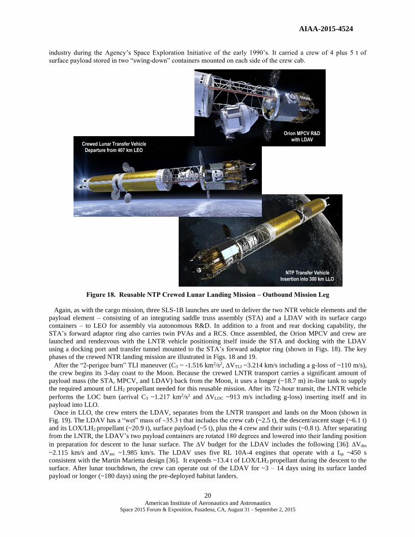
industry during the Agency’s Space Exploration Initiative of the early 1990’s. It carried a crew of 4 plus 5 t of
surface payload stored in two “swing-down” containers mounted on each side of the crew cab.
Figure 18. Reusable NTP Crewed Lunar Landing Mission – Outbound Mission Leg
Again, as with the cargo mission, three SLS-1B launches are used to deliver the two NTR vehicle elements and the
payload element – consisting of an integrating saddle truss assembly (STA) and a LDAV with its surface cargo
containers – to LEO for assembly via autonomous R&D. In addition to a front and rear docking capability, the
STA’s forward adaptor ring also carries twin PVAs and a RCS. Once assembled, the Orion MPCV and crew are
launched and rendezvous with the LNTR vehicle positioning itself inside the STA and docking with the LDAV
using a docking port and transfer tunnel mounted to the STA’s forward adaptor ring (shown in Figs. 18). The key
phases of the crewed NTR landing mission are illustrated in Figs. 18 and 19.
After the “2-perigee burn” TLI maneuver (C3 ~ -1.516 km2/s2, VTLI ~3.214 km/s including a g-loss of ~110 m/s),
the crew begins its 3-day coast to the Moon. Because the crewed LNTR transport carries a significant amount of
payload mass (the STA, MPCV, and LDAV) back from the Moon, it uses a longer (~18.7 m) in-line tank to supply
the required amount of LH2 propellant needed for this reusable mission. After its 72-hour transit, the LNTR vehicle
performs the LOC burn (arrival C3 ~1.217 km2/s2 and VLOC ~913 m/s including g-loss) inserting itself and its
payload into LLO.
Once in LLO, the crew enters the LDAV, separates from the LNTR transport and lands on the Moon (shown in
Fig. 19). The LDAV has a “wet” mass of ~35.3 t that includes the crew cab (~2.5 t), the descent/ascent stage (~6.1 t)
and its LOX/LH2 propellant (~20.9 t), surface payload (~5 t), plus the 4 crew and their suits (~0.8 t). After separating
from the LNTR, the LDAV’s two payload containers are rotated 180 degrees and lowered into their landing position
in preparation for descent to the lunar surface. The V budget for the LDAV includes the following [36]Vdes
~2.115 km/s and Vasc ~1.985 km/s. The LDAV uses five RL 10A-4 engines that operate with a Isp ~450 s
consistent with the Martin Marietta design [36]. It expends ~13.4 t of LOX/LH2 propellant during the descent to the
surface. After lunar touchdown, the crew can operate out of the LDAV for ~3 – 14 days using its surface landed
payload or longer (~180 days) using the pre-deployed habitat landers.
NTP Transfer Vehicle Insertion into 300 km LLO
Crewed Lunar Transfer Vehicle Departure from 407 km LEO
Orion MPCV R&D with LDAV
AIAA-2015-4524
21 American Institute of Aeronautics and Astronautics
Space 2015 Forum & Exposition, Pasadena, CA, August 31 - September 2, 2015
LDAV with Payload in Pre-descent Position
Crewed LDAV Landing Near Habitat Landers
Propulsive Capture into a 24-hr EEO
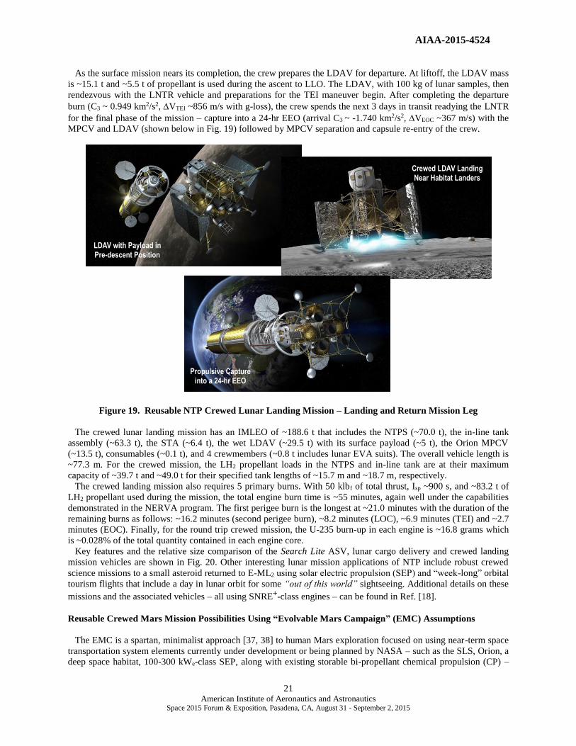
As the surface mission nears its completion, the crew prepares the LDAV for departure. At liftoff, the LDAV mass
is ~15.1 t and ~5.5 t of propellant is used during the ascent to LLO. The LDAV, with 100 kg of lunar samples, then
rendezvous with the LNTR vehicle and preparations for the TEI maneuver begin. After completing the departure
burn (C3 ~ 0.949 km2/s2, VTEI ~856 m/s with g-loss), the crew spends the next 3 days in transit readying the LNTR
for the final phase of the mission – capture into a 24-hr EEO (arrival C3 ~ -1.740 km2/s2, VEOC ~367 m/s) with the
MPCV and LDAV (shown below in Fig. 19) followed by MPCV separation and capsule re-entry of the crew.
Figure 19. Reusable NTP Crewed Lunar Landing Mission – Landing and Return Mission Leg
The crewed lunar landing mission has an IMLEO of ~188.6 t that includes the NTPS (~70.0 t), the in-line tank
assembly (~63.3 t), the STA (~6.4 t), the wet LDAV (~29.5 t) with its surface payload (~5 t), the Orion MPCV
(~13.5 t), consumables (~0.1 t), and 4 crewmembers (~0.8 t includes lunar EVA suits). The overall vehicle length is
~77.3 m. For the crewed mission, the LH2 propellant loads in the NTPS and in-line tank are at their maximum
capacity of ~39.7 t and ~49.0 t for their specified tank lengths of ~15.7 m and ~18.7 m, respectively.
The crewed landing mission also requires 5 primary burns. With 50 klbf of total thrust, Isp ~900 s, and ~83.2 t of
LH2 propellant used during the mission, the total engine burn time is ~55 minutes, again well under the capabilities
demonstrated in the NERVA program. The first perigee burn is the longest at ~21.0 minutes with the duration of the
remaining burns as follows: ~16.2 minutes (second perigee burn), ~8.2 minutes (LOC), ~6.9 minutes (TEI) and ~2.7
minutes (EOC). Finally, for the round trip crewed mission, the U-235 burn-up in each engine is ~16.8 grams which
is ~0.028% of the total quantity contained in each engine core. Key features and the relative size comparison of the Search Lite ASV, lunar cargo delivery and crewed landing
mission vehicles are shown in Fig. 20. Other interesting lunar mission applications of NTP include robust crewed
science missions to a small asteroid returned to E-ML2 using solar electric propulsion (SEP) and “week-long” orbital
tourism flights that include a day in lunar orbit for some “out of this world” sightseeing. Additional details on these
missions and the associated vehicles – all using SNRE+-class engines – can be found in Ref. [18].
Reusable Crewed Mars Mission Possibilities Using “Evolvable Mars Campaign” (EMC) Assumptions
The EMC is a spartan, minimalist approach [37, 38] to human Mars exploration focused on using near-term space
transportation system elements currently under development or being planned by NASA – such as the SLS, Orion, a
deep space habitat, 100-300 kWe-class SEP, along with existing storable bi-propellant chemical propulsion (CP) –

AIAA-2015-4524
22 American Institute of Aeronautics and Astronautics
Space 2015 Forum & Exposition, Pasadena, CA, August 31 - September 2, 2015
Figure 20. Reusable NTP Vehicles for NEA, Lunar Cargo and Crewed Landing Missions
and determining if such missions are possible within the projected annual budgets envisioned for the Agency in the
future. A variety of mission architectures and technology options have been examined for the EMC but most involve
the use of several high power / high Isp SEP cargo tugs to preposition assets in the Mars system prior to crew arrival.
Transit times to Mars for the SEP mission are on the order of 3.5 years [37]. The crewed mission uses CP
(specifically the cryogenic expendable upper stage (EUS) from the SLS) to depart from a high Earth orbit plus a
separate Mars orbit injection (MOI) storable stage for capture into a 1-sol elliptical Mars orbit (EMO) with a 250 km
perigee and ~33,793 km apogee. A prepositioned storable trans-Earth injection (TEI) stage is used for Earth return.
A hybrid SEP/CP architecture [38] would depart from a Lunar Distant Retrograde Orbit (LDRO) where both the
propellant (storable bi-propellant for the CP system and xenon for the SEP stage) and additional logistics required
for the Mars mission would be aggregated and used to outfit the hybrid spacecraft. The Mars crew would R&D with
the hybrid spacecraft only after it had departed its LDRO on a 6-month long transfer to a Lunar Distance High Earth
Orbit (LDHEO) via a solar perturbation loop and a pair of Lunar Gravity Assists (LGAs) [38].
The crew transit time to Mars would be ~200-250 days. On Mars approach, the CP component of the crewed
hybrid system performs the MOI burn and captures into a highly elliptical Mars orbit (HEMO) with a period of ~5 -
10 sol. These larger Mars orbits are required for this architecture and can reduce the propellant requirements on the
storable CP system by more than 50% compared to that required for capture into a 1-sol orbit.
A stepwise approach to human activities is envisioned in the EMC with an orbital survey mission of Mars and a
visit to its moon, Phobos, in 2033, followed by a short-stay landing on Mars in 2039, then a one-year stay in 2043
[37]. Once in Mars orbit, the crewed Mars transfer vehicle (MTV) would rendezvous with the prepositioned assets.
For the Phobos mission this would be a Phobos transfer stage that would carry the Orion capsule with its 4 crew to a
habitat module placed on Phobos during an earlier SEP cargo mission. After an ~1-year stay on Phobos, including
extensive surface exploration and scientific observations of Mars, and a possible stopover at Mars’ other moon,
Deimos, the crew returns to the deep space habit (DSH) in its EMO. Because the MOI stage is drained of propellant
during the capture burn, it is jettisoned and the DSH and Orion are reconfigured with the prepositioned TEI stage. At
the conclusion of the ~500-day stay in the Mars system, the TEI stage sends the DSH and Orion on an ~200-250-day
return trajectory to Earth where the crew performs a direct Earth re-entry and landing using the Orion
capsule. All total, the mission duration would be ~900 – 1000 days in a 0-gEenvironment.
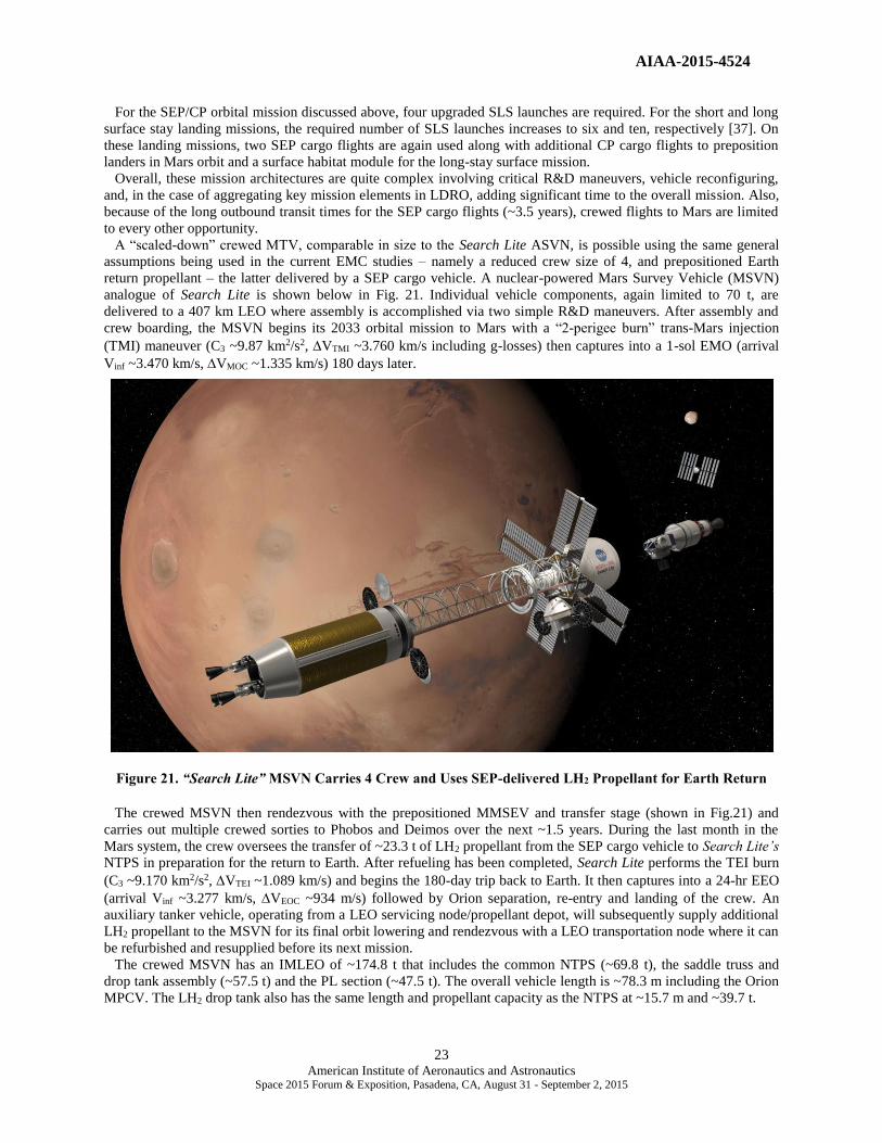
AIAA-2015-4524
23 American Institute of Aeronautics and Astronautics
Space 2015 Forum & Exposition, Pasadena, CA, August 31 - September 2, 2015
For the SEP/CP orbital mission discussed above, four upgraded SLS launches are required. For the short and long
surface stay landing missions, the required number of SLS launches increases to six and ten, respectively [37]. On
these landing missions, two SEP cargo flights are again used along with additional CP cargo flights to preposition
landers in Mars orbit and a surface habitat module for the long-stay surface mission.
Overall, these mission architectures are quite complex involving critical R&D maneuvers, vehicle reconfiguring,
and, in the case of aggregating key mission elements in LDRO, adding significant time to the overall mission. Also,
because of the long outbound transit times for the SEP cargo flights (~3.5 years), crewed flights to Mars are limited
to every other opportunity.
A “scaled-down” crewed MTV, comparable in size to the Search Lite ASVN, is possible using the same general
assumptions being used in the current EMC studies – namely a reduced crew size of 4, and prepositioned Earth
return propellant – the latter delivered by a SEP cargo vehicle. A nuclear-powered Mars Survey Vehicle (MSVN)
analogue of Search Lite is shown below in Fig. 21. Individual vehicle components, again limited to 70 t, are
delivered to a 407 km LEO where assembly is accomplished via two simple R&D maneuvers. After assembly and
crew boarding, the MSVN begins its 2033 orbital mission to Mars with a “2-perigee burn” trans-Mars injection
(TMI) maneuver (C3 ~9.87 km2/s2, VTMI ~3.760 km/s including g-losses) then captures into a 1-sol EMO (arrival
Vinf ~3.470 km/s, VMOC ~1.335 km/s) 180 days later.
Figure 21. “Search Lite” MSVN Carries 4 Crew and Uses SEP-delivered LH2 Propellant for Earth Return
The crewed MSVN then rendezvous with the prepositioned MMSEV and transfer stage (shown in Fig.21) and
carries out multiple crewed sorties to Phobos and Deimos over the next ~1.5 years. During the last month in the
Mars system, the crew oversees the transfer of ~23.3 t of LH2 propellant from the SEP cargo vehicle to Search Lite’s
NTPS in preparation for the return to Earth. After refueling has been completed, Search Lite performs the TEI burn
(C3 ~9.170 km2/s2, VTEI ~1.089 km/s) and begins the 180-day trip back to Earth. It then captures into a 24-hr EEO
(arrival Vinf ~3.277 km/s, VEOC ~934 m/s) followed by Orion separation, re-entry and landing of the crew. An
auxiliary tanker vehicle, operating from a LEO servicing node/propellant depot, will subsequently supply additional
LH2 propellant to the MSVN for its final orbit lowering and rendezvous with a LEO transportation node where it can
be refurbished and resupplied before its next mission.
The crewed MSVN has an IMLEO of ~174.8 t that includes the common NTPS (~69.8 t), the saddle truss and
drop tank assembly (~57.5 t) and the PL section (~47.5 t). The overall vehicle length is ~78.3 m including the Orion
MPCV. The LH2 drop tank also has the same length and propellant capacity as the NTPS at ~15.7 m and ~39.7 t.

AIAA-2015-4524
24 American Institute of Aeronautics and Astronautics
Space 2015 Forum & Exposition, Pasadena, CA, August 31 - September 2, 2015
The reusable crewed MSVN requires 5 primary burns (4 restarts) that use ~93.0 t of LH2 propellant. With ~50 klbf
of total thrust and a Isp of ~900 s, the total engine burn time is ~61.5 minutes. The first of the two TMI perigee burns
is the longest single burn at ~24.2 minutes after which the vehicle’s drop tank is drained and jettisoned. The duration
of the remaining burns are as follows: ~13.6 minutes (second TMI perigee burn), ~9.2 minutes (MOC), ~8.3 minutes
(TEI) and ~6.2 minutes (EOC). For this round trip crewed Mars mission, the U-235 burn-up is ~18.8 grams which is
~0.032% of the total quantity found in each engine.
With reduced crew size and prepositioned return propellant at Mars, smaller, reusable MTVs using SNRE+-class
engines are possible allowing simpler mission architectures with shorter crew transit times to and from Mars thus
reducing their exposure to the debilitating effects of 0-gE and the energetic particle radiation permeating space. As
discussed above, the SNRE+ can also be used for variety of future human exploration missions and the performance
requirements on the GC fuel and the engine system appear quite reasonable. The engine operational parameters for
the missions discussed above are summarized in Table 2 and assume a peak fuel temperature of 2860 K and a HEU
fuel loading of ~0.6 grams per cm3. Other key reactor and engine design / performance characteristics are
summarized in Table 1.
Table 2. Small Engine Operational Parameters for FTD, Cargo Delivery and Crewed Exploration Missions
Requirements
Missions
Engine
Thrust
(klbf)
T/Weng
Tex
(oK)
Isp
(s)
No.
Engines
U-235
Mass
(kg)
No.
Burns
Longest
Single
Burn (min)
Total
Burn Time
(min)
U-235
Burnup
(%)
Lunar Flyby
FTD Mission ~7.5 ~1.9 2739 894 1 27.5 1 ~13.0 - ~0.0062
Lunar Flyby
FTD Mission ~16.7 ~3.1 2733 900 1 59.6 1 ~6.7 - ~0.0035
Lunar Cargo
Delivery ~16.7 ~3.1 2733 900 3 59.6 5 ~21.4 ~49.2 ~0.025
Lunar Landing
Crewed ~16.7 ~3.1 2733 900 3 59.6 5 ~21.0 ~55.0 ~0.028
NEA 2000 SG344
Crewed ~16.7 ~3.1 2733 900 3 59.6 5 ~27.4 ~50.4 ~0.026
EMC Crewed ~16.7 ~3.1 2733 900 3 59.6 5 ~24.2 ~61.5 ~0.032
VIII. Notional Schedule to Flight Details
Assumptions Made in Schedule Formulation
In FY’14, a preliminary development schedule / DDT&E plan was produced by GRC, DOE and industry for the
AES program. It assumed a 10-year duration during which time a ground tested and qualified engine would be
readied for flight demonstration around the ~2025 timeframe. By necessity, the project would be a success-oriented,
high-risk activity requiring an immediate start and dedicated financial commitment by NASA. It also assumed the
following: (1) a streamlined management and acquisition strategy; (2) use of GC fuel; (3) an immediate scale up in
FE production levels before verification of all fuel processing activities are completed; (4) utilization of existing
facilities (e.g., DAF) and borehole or tunnel testing at the NNSS; (5) starting NEPA (National Environmental Policy
Act) and launch safety analyses; (6) identifying fuel and reactor transportation requirements; and (7) initiating
facility modifications at the Cape required for assembly, test, and launch operations (ATLO).
The schedule also assumed co-location of a portable hot cell unit (like the mobile SHARS unit) near the site where
testing is to occur. The unit would be a “turnkey” procurement and used to disassemble the reactor after testing to
extract a sampling of FEs and reactor components for shipment to INL for PIE as discussed in Sect IV. Afterwards,
the unit would package smaller groupings of fuel and reactor components for shipment in existing casks to a DOE
facility for processing and disposal thus avoiding the added expense and time to develop a new “Cat 1” container.

AIAA-2015-4524
25 American Institute of Aeronautics and Astronautics
Space 2015 Forum & Exposition, Pasadena, CA, August 31 - September 2, 2015
Lastly, it was assumed that the GTD project would build and test two units; the first being an engineering
reactor/engine test article with ~90% design fidelity in 2023 and the second unit being a qualification engine with
~100% design fidelity in 2024. The final flight unit – identical to the qualification unit – would be launched in 2025.
Parallel Activities and Other Important Considerations in Schedule Development
A number of activities need to occur before a SNTPS can be launched. These include: (1) Fuel and reactor
materials development and qualification; (2) Reactor and engine design; (3) GTF design, construction and checkout;
(4) Ground test article development, fabrication and demonstrations; (5) Flight system design and fabrication; (6)
Transportation (for both the ground test articles and flight unit); (7) Engine, stage and launch vehicle integration and
checkout at the Cape; and then (8) Launch.
Reactor design can be performed in parallel with fuel development and qualification so that reactors can be
fabricated as soon as acceptable reactor fuel is available and the necessary facilities and test infrastructure are in
place and available. Three primary activities must therefore begin in the initial phase of a flight development
program: (1) fuel development and qualification; (2) integrated reactor, engine and stage design; and (3) GTF
selection, design, and construction. Fuel development and qualification will include fuel performance validation and
documentation of the fuel fabrication process parameters and specifications, required source materials and
equipment necessary to insure reproducibility. With this information private sector vendors can be engaged to scale
up fuel fabrication from lab-scale single element extrusions to an established fuel fabrication line capable of the
producing the large numbers of HEU fuel elements needed for the ground test articles and the flight engine.
The availability of required facilities is another important consideration. In addition to the GTF and fuel
fabrication facility, a number of other nuclear and nuclear-related test facilities will be required to successfully
execute this program. Facilities for conducting cold and hot critical experiments and establishing component
tolerance limits to neutron and gamma radiation will need to be identified at existing DOE facilities or new
analogues will have to be built. Other likely facilities include reactor component and control system test facilities, as
well as, simulator facilities to help train and prepare the operators who will be conducting the actual engine ground
testing.
Schedule Task Activities and Timing
Key task activities associated with the ground and flight technology demonstration schedule are shown in Fig. 22.
The schedule assumes GC fuel is selected as the lead fuel option consistent with the IRP’s recommendation and the
AES program’s endorsement of this fuel option this past February. As discussed above, there are three activities that
start immediately. The first is GC fuel and coating development and qualification. It uses separate effects testing
involving NTREES and irradiation testing conducted in either the High Flux Isotope Reactor (HFIR) at ORNL or
the ATR at INL. Once qualified, fuel element fabrication begins using HEU at either ORNL’s Y-12 Facility or an
industry contractor. Second is engine design and development. This work will be performed by a government/
industry contractor team who will provide the necessary design details needed for the mission concept, system
requirements, preliminary and critical design reviews that occur over the next 4 years. Third is GTF concept
evaluation and selection between the borehole and tunnel options (at either P-tunnel or the U1a complex).
New facility development, whether for a GTF or fuel fabrication facility, is typically a long lead item within DOE
involving a 5-year design, construction and checkout period. DOE will need to submit a budget request by Critical
Decision-0 (CD-0) before starting conceptual design, preparing NEPA documentation, and seeking permit approval
from the state with regulatory authority. This information provides the basis for continuing with facility preliminary
design (CD-1). Approval for final design and construction start occurs during CD-2 and CD-3, respectively.
Operator training, facility qualification and Operational Readiness Review (ORR) occur during CD-4. Prior to
preliminary design of the GTF, non-nuclear subscale validation testing of the selected concept may be required.
Validation testing of the SAFE concept is shown as an example in Fig. 22.
Design and development activities on the stage start after engine design and development is underway. The
DDT&E effort on the non-nuclear engine and stage components is not expected to be a pacing element in the
development schedule since many of these components and subsystems already exist and have flown in space as
discussed Section VI. The main technical issue is material and component tolerance to a radiation environment for
short periods and whether selective use of particular types of materials may be required. Candidate fabrication
materials for NTP TPAs, nozzles, controls, valves and instrumentation were identified and documented by Aerojet
and demonstrated during extensive testing on the NERVA program’s NRX-XE experimental engine in 1969 [4].

AIAA-2015-4524
26 American Institute of Aeronautics and Astronautics
Space 2015 Forum & Exposition, Pasadena, CA, August 31 - September 2, 2015
AIAA-2015-4524
27 American Institute of Aeronautics and Astronautics
Space 2015 Forum & Exposition, Pasadena, CA, August 31 - September 2, 2015
In parallel with GTF qualification, ORR and start of operations, components for the first engineering ground test
article will be fabricated and sent to DAF for assembly, then installed and tested at the GTF in 2023. The
installation, test and post-test evaluation process is expected to take ~6-9 months. Similar fabrication and assembly
of the second test article, the qualification unit, will occur in 2023 followed by its installation and testing in 2024.
After the ground test campaign is finished, program focus will shift to the FTD mission and activities at the Cape.
Fabrication and assembly of the reactor subsystem for the flight unit would be done at the industry contactor. The
unit will then be shipped to the Cape for acceptance testing and integration with its non-nuclear engine components,
the flight stage and launch vehicle.
The launch approval process will require preparation of a FSAR (Final Safety Analysis Report) and a SER (Safety
Evaluation Report) by DOE and INSRP (Interagency Nuclear Safety Review Panel), respectively, along with
Operational and Mission Readiness Reviews by NASA before approval to proceed with the mission is provided by
the White House Office of Science and Technology Policy (OSTP) leading to a launch in late 2025.
After the GTD tests and FTD mission, other single engine NTP robotic science missions are possible [39]. This
would be followed by a clustered engine demonstration of the NTPS (e.g., on a lunar cargo delivery flight) before
being used on the crewed exploration missions discussed above.
IX. Summary and Concluding Remarks
Today, NASA is providing modest funding for a small but focused technology development effort that it hopes
will lead to the successful ground testing and eventual flight of a small NTR engine within a 10-year period.
Following the IRP recommendation and AES program endorsement of graphite composite fuel as the “lead fuel”
option, the NTP project is now focused on fabricating and testing GC fuel elements. An ~16 inch partial length FE
with 4-holes and ZrC coating has been fabricated by ORNL and will undergo non-nuclear “thermal cycling” tests in
NTREES in FY’15 – a major project milestone. NTREES testing of a coated 19-hole element containing depleted
uranium will be conducted next, followed by irradiation testing in a DOE reactor in the FY’16-17 timeframe.
In addition to recapturing and demonstrating GC fuel fabrication and coating processes using current day
equipment and source materials, NASA and DOE are also using SOTA computational tools to develop conceptual
designs for several small engines – one a criticality limited 7.5 klbf engine and the other an updated version of the
SNRE producing just under 16.7 klbf of thrust. Both engines are candidates for ground testing and flight
demonstration, but the SNRE+ option is recommended for development for the following reasons: (1) it has design
heritage and a previously developed program plan that can provide a point of comparison to the current effort; (2)
its FE – TT arrangement and TT configuration are the same as that used in larger engine designs; (3) it uses the
same 35 inch long FEs and is only slightly longer than the 7.5 klbf engine despite its higher thrust output; and (4) it
can be used for the single engine FTD mission, and with three clustered engines can support reusable lunar cargo
delivery, crewed landing, and NEA survey missions. Even human missions to Mars are possible with the smaller
crew size and prepositioning of assets currently being envisioned in NASA’s EMC. This can lead to an affordable
“one size fits all” approach to NTR development using the SNRE-class graphite composite engine.
Regarding ground testing, NASA and DOE personnel have twice traveled to the NNSS in the past year and a half,
visiting the DAF and touring candidate ground test locations including a vertical borehole, and horizontal tunnels at
the underground U1a and P-tunnel complexes. The pros and cons of testing at each of these locations have been
discussed and a Concept of Operations for ground testing has been outlined.
The preliminary DDT&E plan and schedule for affordably ground and flight-testing a small NTR engine and
stage, developed by GRC, DOE and industry, has been presented. The assumptions and important considerations
used in developing the schedule and the key task activities included in it have also been discussed.
The keys to affordability include using: (1) proven “graphite composite” fuel with its well-documented fabrication
processes and large database; (2) “separate effects” testing (e.g., NTREES and irradiation) to qualify the fuel and
coatings; (3) SOTA “benchmarked” numerical models to design, build and operate the engine computationally; (4)
the SNRE+design with its “common” FE – TT arrangement that is scalable to larger thrust levels when and if
required; (5) existing DOE facilities and infrastructure at the NNSS (e.g., DAF, boreholes or tunnels); and (6)
flight-proven, non-nuclear engine and stage hardware to the maximum extent possible for the FTD mission.
Although not discussed in this paper, a rough order of magnitude (ROM) cost estimate was made for the GTD
tests and FTD mission. It is premature, however, to discuss cost at this time since the AES program has just
requested a more in-depth requirements assessment and cost estimate be made by the NTP project over the next two
years. The information presented here will provide a good starting point for that assessment.

AIAA-2015-4524
28 American Institute of Aeronautics and Astronautics
Space 2015 Forum & Exposition, Pasadena, CA, August 31 - September 2, 2015
Acknowledgments
The authors wish to thank Chris Moore and John Warren (AES Division), Anthony Belvin (DOE/NE-75) and
Mark Klem (GRC) for their continued encouragement and strong support of this work. The author (SKB) also
expresses his thanks to Mike Trammel and Brian Jolly (ORNL) for the fuel element fabrication and coating
equipment pictures shown in Figs. 9 and 10, Bob Cataldo (GRC) for the ConOps illustration in Fig. 11, and Bob
Sauls ([email protected]) for the digital images depicted in Figs. 15 – 21 of this paper.
References
[1] Nuclear Cryogenic Propulsion Stage Project Fuel Evaluation and Recommendation Report to the Independent
Review Panel, prepared by the Nuclear Cryogenic Propulsion Stage Fuel Evaluation Committee, January 2015.
[2] Emrich, William J., Moran, R. P., and Pearson, J. B., “Nuclear Thermal Rocket Element Environmental
Simulator (NTREES) Upgrade Activities”, AIAA- 2012-4307, July 2012.
[3] Howe, Steven D., et al., “Ground Testing a Nuclear Thermal Rocket: Design of a Sub-scale Demonstration
Experiment”, AIAA-2012-3743, July 2012.
[4] Koeing, D. R., “Experience Gained from the Space Nuclear Rocket Programs (Rover/NERVA)”, Los
Alamos National Laboratory, Report LA-10062-H, Los Alamos, NM, May 1986.
[5] Taub, J. M., “A Review of Fuel Element Development for Nuclear Rocket Engines”, Los Alamos National
Laboratory, Report LA-5931, Los Alamos, NM, June 1975.
[6] Durham, F. P., “Nuclear Engine Definition Study Preliminary Report, Volume I - Engine Description”, Los
Alamos National Laboratory, Report LA-5044-MS Vol. I, Los Alamos, NM, September 1972.
[7] Human Exploration of Mars Design Reference Architecture 5.0, Drake, Bret G., ed., National Aeronautics and
Space Administration, NASA-SP-2009-566, Washington, DC, July 2009.
[8] Borowski, S. K., McCurdy, D. R., and Packard, T. W., “7-Launch NTR Space Transportation System for
NASA’s Mars Design Reference Architecture (DRA) 5.0”, AIAA-2009-5308, August 2009.
[9] 710 High-Temperature Gas Reactor Program Summary Report, General Electric, Report GEMP-600, Volume 1,
Cincinnati, OH, 1968. [10] Nuclear Rocket Program Terminal Report, Argonne National Laboratory, Report ANL-7236, Argonne, IL,
1968.
[11] Schnitzler, Bruce G., and Borowski, Stanley K., “Neutronics Models and Analysis of Small Nuclear
Rocket Engine (SNRE)”, AIAA-2007-5618, July 2007.
[12] Stewart, Mark E., and Schnitzler, Bruce G., “Thermal Hydraulics and Structural Analysis of the Small Nuclear
Rocket Engine (SNRE) Core”, AIAA-2007-5619, July 2007.
[13] Fittje, James E., “Upgrades to the NESS (Nuclear Engine System Simulation) Code”, AIAA-2007-5620, July
2007.
[14] Schnitzler, B. G., Borowski, S. K., and Fittje, J. E., “25,000-lbf Thrust Engine Options Based on the Small
Nuclear Rocket Engine Design”, AIAA-2009-5239, August 2009.
[15] Schnitzler, B. G., Borowski, S. K., and Fittje, J. E., “Lower Thrust Engine Options Based on the Small Nuclear
Rocket Engine Design”, AIAA-2011-5846, August 2011.
[16] Schnitzler, B. G., “Recommended Point-of-Departure Designs of Small Reactors Suitable for Direct Nuclear
Thermal Propulsion”, Oak Ridge National Laboratory, Oak Ridge, TN, October 2014.
[17] Durham, F. P., “Nuclear Engine Definition Study Preliminary Report, Volume III - Preliminary Program Plan”,
Los Alamos National Laboratory, Report LA-5044-MS Vol. III, Los Alamos, NM, September 1972.
[18] Borowski, S. K., McCurdy, D. R., and Burke, L. M., “The Nuclear Thermal Propulsion Stage (NTPS): A Key
Space Asset for Human Exploration and Commercial Missions to the Moon”, AIAA-2013-5465, September 2013.
[19] Borowski, S. K., McCurdy, D. R., and Packard, T. W., “Modular Growth NTR Space Transportation System
for Future NASA Human Lunar, NEA and Mars Exploration Missions”, AIAA-2012-5144, September 2012.
[20] Lyon, L. L., "Performance of (U,Zr)C-Graphite (Composite) and of (U,Zr)C (Carbide) Fuel Elements in the
Nuclear Furnace 1 Test Reactor”, Los Alamos National Laboratory. Report LA-5398-MS, Los Alamos, NM,
September 1973. [21] Davidson, K. V., Martin, W. M., Shell, D. H., Taub, J. M., and Taylor, J. W., “Development of Carbide-Carbon
Composite Fuel Elements for Rover Reactors”, LA-5005, Los Alamos National Laboratory, October 1972.
[22] Trammell, M. P., Jolly, B. C., and Qualls, A. L., “Extrusion Development of Graphite-Based Composite Fuel
for Nuclear Thermal Propulsion”, AIAA-2015-3776, July 2015.

AIAA-2015-4524
29 American Institute of Aeronautics and Astronautics
Space 2015 Forum & Exposition, Pasadena, CA, August 31 - September 2, 2015
[23] Caputo, A. J., “NERVA Fuel Element Development Program Summary Report: July 1966 – June 1972,
Characterization of Vapor Deposited Niobium and Zirconium Carbides,” Y-12 Plant report Y-1852 Part 3, Oak
Ridge National Laboratory, Oak Ridge, TN (1973).
[24] Caputo, A. J., “NERVA Fuel Element Development Program Summary Report: July 1966 – June 1972, Vapor
Deposition of Metal Carbides,” Y-12 Plant report Y-1852 Part 4, Oak Ridge National Laboratory, Oak Ridge, TN
(1973).
[25] Jolly, B. C., Trammell, M. P., and Qualls, A. L., “Coating Development on Graphite-Based Composite Fuel for
Nuclear Thermal Propulsion”, AIAA-2015-3777, July 2015.
[26] Raj, S. V., and Nesbitt, J. A., “Development of Advanced Coatings for NERVA-type Fuel Elements”,
NETS2015-5072, Nuclear and Emerging Technologies for Space (NETS) 2015, Albuquerque, NM, February 2015.
[27] Coote, D., “Review of Nuclear Thermal Propulsion Ground Test Options”, NETS2015-5146, Nuclear and
Emerging Technologies for Space (NETS) 2015, Albuquerque, NM, February 2015.
[28] Howe, S. D., Travis, B., and Zerkle, D.K., “SAFE Testing of Nuclear Rockets”, Journal of Propulsion and
Power, Vol. 17, No. 3, pg. 534-539 (2001).
[29] Marshall, W. M., “Subscale Validation of the Subsurface Active Filtration of Exhaust (SAFE) Approach to
NTP Ground Testing”, AIAA-2015-3775, July 2015.
[30] “SHARS - A Shared Solution for Risky Radioactive Sources”, IAEA Bulletin 49/1, September 2007.
[31] Joyner, C. R., Levack, D., and Borowski, S. K., “Affordable Development of a Nuclear Thermal Propulsion
Flight Demonstrator Based on a Small Propulsion Engine that is Scalable to Human Missions”, GLEX-
2012.4.4x12224, Global Space Exploration Conference, Washington, DC, May 2012.
[32] Fittje, J. E., Borowski, S. K., and Schnitzler, B. G., “Parametric Analysis of a 75 kN Thrust Class Composite
Fuel Based NTR Engine”, AIAA-2014-3431, July 2014.
[33] Ferlin, M., “Assessment and Benchmarking of Extendible Nozzle Systems for Liquid Propulsion Engines,”
AIAA 2012-4136, August 2012.
[34] Santiago, J, R., “Evolution of the RL-10 Liquid Rocket Engine for a New Upperstage Application,” AIAA 96-
3013, July 1996.
[35] Borowski, S. K., Sefcik, R. J., Fittje, J. E., McCurdy, D. R., Qualls, A. L., Schnitzler, B. G., et al., “Affordable
Development and Demonstration of a Small NTR Engine and Stage: A Preliminary NASA, DOE and Industry
Assessment”, AIAA 2015-3774, July 2015.
[36] Hodge, J., et al., “Space Transfer Vehicle – Lunar Transportation Ground Based LEO Rendezvous and Docking
Study”, NAS8-37856, Martin Marietta, August 1991.
[37] Price, H. W., Baker, J. D., and Naderi, F., “A Minimal Architecture for Human Journeys to Mars”, New Space,
Vol. 13, No. 2, pg. 73-81 (2015).
[38] Merrill, R. G., Strange, N., Qu, M., and Hatten, N., “Mars Conjunction Crewed Missions with a Reusable
Hybrid Architecture”, IEEE Aerospace Conference, 2015-8.0104, March 2015.
[39] Joyner, C. R., Kokan, T. S., and Levack, D. J. H., “Solar System Missions with a Small Nuclear Thermal
Propulsion Stage”, NETS2013-6717, Nuclear and Emerging Technologies for Space (NETS) 2013, Albuquerque,
NM, February 2013.