after completing this chapter, you will be able to: design...
TRANSCRIPT

After completing this chapter, you will be able to:
■ Design addressing solutions to support summariza-tion
■ Design routing solutions to support summarization,route filtering, and redistribution
■ Design scalable EIGRP routing solutions for the en-terprise
■ Design scalable OSPF routing solutions for the en-terprise
■ Design scalable BGP routing solutions for the enter-prise

CHAPTER 3
Developing an Optimum Design for Layer 3
This chapter examines a select number of topics on both advance IP addressing and selectdesign issues with Border Gateway Protocol (BGP), Enhanced Interior Gateway RoutingProtocol (EIGRP), and Open Shortest Path First (OSPF). As one would expect, advancedIP addressing and routing protocol design encompasses a large amount of detail that hasalready filled a number of books on routing protocols and networking best practices. Thetext will parallel topics covered in the Design course.
Designing Advanced IP Addressing
Designing IP addressing at a professional level involves several advanced considerations. Thissection reviews the importance of IP address planning and selection and the importance ofIP address summarization. It also discusses some applications of summary addressing.
IP Address Planning as a Foundation
Structured and modular cabling plant and network infrastructures are ideal for a good de-sign with low maintenance and upgrade costs. In similar fashion, a well-planned IP ad-dressing scheme is the foundation for greater efficiency in operating and maintaining anetwork. Without proper planning in advance, networks may not be able to benefit fromroute summarization features inherent to many routing protocols.
Route summarization is important in scaling any routing protocol. However, some existingIP addressing schemes may not support summarization. It takes time and effort to prop-erly allocate IP subnets in blocks to facilitate summarization. The benefit of summarizedaddresses is reduced router workload and routing traffic. Although modern router CPUscan handle a vastly increased workload as compared to older routers, reducing load miti-gates the impact of periods of intense network instability. In general, summary routesdampen out or reduce network route churn, making the network more stable. In addition,summary routes lead to faster network convergence. Summarized networks are simpler totroubleshoot because there are fewer routes in the routing table or in routing advertise-ments, compared to nonsummarized networks.
Just as using the right blocks of subnets enables use of more efficient routing, care withsubnet assignments can also support role-based functions within the addressing schemestructure. This in turn enables efficient and easily managed access control lists (ACL) forquality of service (QoS) and security purposes.

88 Designing Cisco Network Service Architectures (ARCH)
In addition to allocating subnets in summarized blocks, it is advantageous to chooseblocks of addresses within these subnets that can be easily summarized or described us-ing wildcard masking in ACLs. With a well-chosen addressing scheme, ACLs can becomemuch simpler to maintain in the enterprise.
Summary Address Blocks
Summary address blocks are the key to creating and using summary routes. How do yourecognize a block of addresses which can be summarized? A block of IP addresses mightbe able to be summarized if it contains sequential numbers in one of the octets. The se-quence of numbers must fit a pattern for the binary bit pattern to be appropriate for sum-marization. The pattern can be described without doing binary arithmetic.
For the sequential numbers to be summarized, the block must be x numbers in a row,where x is a power of 2. In addition, the first number in the sequence must be a multipleof x. The sequence will always end before the next multiple of x.
For example, any address block that matches the following is able to be summarized:
■ 128 numbers in a row, starting with a multiple of 128 (0 or 128)
■ 64 numbers in a row, starting with a multiple of 64 (0, 64, 128, or 192)
■ 32 numbers in a row, starting with a multiple of 32
■ 16 numbers in a row, starting with a multiple of 16
If you examine 172.19.160.0 through 172.19.191.0, there are 191 – 160 + 1 = 32 numbers ina row, in sequence in the third octet. Note that 32 is 25, a power of 2. Note also that 160 isa multiple of 32 (5 * 32 = 160). Because the range meets the preceding conditions, the se-quence 172.19.160.0 through 172.19.191.0 can be summarized.
Finding the correct octet for a subnet-style mask is fairly easy with summary addressblocks. The formula is to subtract N from 256. For example, for 32 numbers in a row, themask octet is 256 – 32 = 224. Because the numbers are in the third octet, you place the224 in the third octet, to form the mask 255.255.224.0.
A summary route expressed as either 172.19.160.0, 255.255.224.0, or as 172.169.160/19would then describe how to reach subnets starting with 172.19.160.0 through 172.19.191.0.
Changing IP Addressing Needs
IP address redesign is needed to adapt to changes in how subnets are now being used. Insome networks, IP subnets were initially assigned sequentially. Summary address blocksof subnets were then assigned to sites to enable route summarization.
However, new requirements are developing requiring additional subnets:
■ IP telephony: Additional subnets or address ranges are needed to support voice serv-ices. In some cases, the number of subnets double when IP telephony is implementedin an organization.
■ Layer 3 switching at the edge: Deploying Layer 3 switching to the network edgeis another trend driving the need for more subnets. Edge Layer 3 switching can create

Chapter 3: Developing an Optimum Design for Layer 3 89
the need for a rapid increase in the number of smaller subnets. In some cases, therecan be insufficient address space, and readdressing is required.
■ Network Admission Control (NAC): NAC is also being deployed in many organiza-tions. Some Cisco 802.1X and NAC deployments are dynamically assigning VLANsbased on user logins or user roles. In these environments, ACLs control connectivityto servers and network resources based on the source subnet, which is based on theuser role.
■ Corporate requirements: Corporate governance security initiatives are also isolat-ing groups of servers by function, sometimes called “segmentation.” Describing “pro-duction” and “development” subnets in an ACL can be painful unless they have beenchosen wisely. These new subnets can make managing the network more complex.Maintaining ad hoc subnets for voice security and other reasons can be time-consuming.When it is possible, describing the permitted traffic in a few ACL statements is ahighly desirable. Therefore, ACL-friendly addressing which can be summarized helpsnetwork administrators to efficiently manage their networks.
Planning Addresses
The first step in implementing ACL-friendly addressing is to recognize the need. In an en-vironment with IP phones and NAC implemented, you will need to support IP phone sub-nets and NAC role subnets in ACLs. In the case of IP phones, ACLs will probably be usedfor both QoS and voice-security rules. For NAC role-based subnets, ACLs will most likelybe used for security purposes.
Servers in medium-to-large server farms should at least be grouped so that servers withdifferent functions or levels of criticality are in different subnets. That saves listing indi-vidual IP addresses in lengthy ACLs. If the servers are in subnets attached to different ac-cess switches, it can be useful to assign the subnets so that there is a pattern suitable forwildcarding in ACLs.
If the addressing scheme allows simple wildcard rules to be written, those simple ACLrules can be used everywhere. This avoids maintaining per-location ACLs that need to de-fine source or destination addresses to local subnets. ACL-friendly addressing supportsmaintaining one or a few global ACLs, which are applied identically at various controlpoints in the network. This would typically be done with a tool such as Cisco SecurityManager.
The conclusion is that it is advantageous to build a pattern into role-based addressing andother addressing schemes so that ACL wildcards can match the pattern. This in turn sup-ports implementing simpler ACLs.
Applications of Summary Address Blocks
Summary address blocks addressing can be used to support several network applications:
■ Separate VLANs for voice and data, and even role-based addressing
■ Bit splitting for route summarization
■ Addressing for virtual private network (VPN) clients

90 Designing Cisco Network Service Architectures (ARCH)
■ Network Address Translation (NAT)
These features are discussed in greater detail in the following sections.
Implementing Role-Based Addressing
The most obvious approach to implement role-based addressing is to use network 10. Thishas the virtue of simplicity. A simple scheme that can be used with Layer 3 closets is touse 10.number_for_closet.VLAN.x /24 and avoid binary arithmetic. This approach usesthe second octet for closets or Layer 3 switches, the third octet for VLANs, and the fourthoctet for hosts.
If you have more than 256 closets or Layer 3 switches to identify in the second octet, youmight use some bits from the beginning of the third octet, because you probably do nothave 256 VLANs per switch.
Another approach is to use some or all of the Class B private addressing blocks. This ap-proach will typically involve binary arithmetic. The easiest method is to allocate bits usingbit splitting. An example network is 172.0001 xxxx.xxxx xxxx.xxhh hhhh. In this case,you start out with 6 bits reserved for hosts in the fourth octet, or 62 hosts per subnet(VLAN). The x bits are to be split further.
This format initially uses decimal notation to the first octet and binary notation in the sec-ond, third, and fourth octets to minimize conversion back and forth.
If you do not need to use the bits in the second octet to identify additional closets, youend up with something like 172.16.cccc cccR.RRhh hhhh:
■ The c characters indicate that 7 bits allow for 27 or 128 closet or Layer 3 switches.
■ The R characters indicate 3 bits for a role-based subnet (relative to the closet block),or 8 roles per switch.
■ The h characters indicate 6 bits for the 62-host subnets specified.
This addressing plan is enough to cover a reasonably large enterprise network.
Another 4 bits are available to work with in the second octet if needed.
Using a role-aware or ACL-friendly addressing scheme, you can write a small number ofglobal permit or deny statements for each role. This greatly simplifies edge ACL mainte-nance. It is easier to maintain one ACL for all edge VLANs or interfaces than differentACLs for every Layer 3 access or distribution switch.
Bit Splitting for Route Summarization
The previous bit-splitting technique has been around for a while. It can also be useful incoming up with summary address block for routing protocols if you cannot use simpleoctet boundaries. The basic idea is to start with a network prefix, such as 10.0.0.0, or a pre-fix in the range 172.16.0.0 to 172.31.0.0, 192.168.n.0, or an assigned IP address. The re-maining bits can then be thought of as available for use for the area, subnet, or host partof the address. It can be useful to write the available bits as x, then substitute a, s, or h as

Chapter 3: Developing an Optimum Design for Layer 3 91
they are assigned. The n in an address indicates the network prefix portion of the address,which is not subject to change or assignment.
Generally, you know how big your average subnets need to be in buildings. (A subnet with64 bits can be summarized and will cover most LAN switches.) That allows you to convertsix x bits to h for host bits.
You can then determine how many WAN links you need and how many you are comfort-able putting into one area to come up with how many a bits you need to assign. The left-over bits are s bits. Generally, one does not need all the bits, and the remaining bits (the aversus s boundary) can be assigned to allow some room for growth.
For example, suppose 172.16.0.0 is being used, with subnets of 62 hosts each. That com-mits the final 6 bits to host address in the fourth octet. If you need 16 or fewer areas, youmight allocate 4 a bits for area number, which leaves 6 s bits for subnet. That would be 26
or 64 subnets per area, which is quite a few.
Example: Bit Splitting for Area 1
This example illustrates how the bit-splitting approach would support the addresses inOSPF area 1. Writing “1” as four binary bits substitutes “0001” for the a bits. The area 1addresses would be those with the bit pattern 172.16.0001 ssss.sshh hhhh. This bit patternin the third octet supports decimal numbers 16 to 31. Addresses in the range 172.16.16.0to 172.16.31.255 would fall into area 1. If you repeat this logic, area 0 would have ad-dresses 172.16.0.0 to 172.16.15.255, and area 2 would have addresses 172.16.32.0 to172.16.47.255.
Subnets would consist of an appropriate third octet value for the area they are in, togetherwith addresses in the range 0 to 63, 64 to 127, 128 to 191, or 192 to 255 in the last octet.Thus, 172.16.16.0/26, 172.16.16.64/26, 172.16.16.128/26, 172.16.16.192/26, and172.16.17.0/26 would be the first five subnets in area 1.
One recommendation that preserves good summarization is to take the last subnet in eacharea and divide it up for use as /30 or /31 subnets for WAN link addressing.
Few people enjoy working in binary. Free or inexpensive subnet calculator tools can help.For those with skill writing Microsoft Excel spreadsheet formulas, you can install ExcelToolkit functions to help with decimal-to-binary or decimal-to-hexadecimal conversion.You could then build a spreadsheet that lists all area blocks, subnets, and address assign-ments.
Addressing for VPN Clients
Focusing some attention on IP addressing for VPN clients can also provide benefits. Asrole-based security is deployed, there is a need for different groupings of VPN clients.These might correspond to administrators, employees, different groups of contractors orconsultants, external support organizations, guests, and so on. You can use different VPNgroups for different VPN client pools.
Role-based access can be controlled via the group password mechanism for the CiscoVPN client. Each group can be assigned VPN endpoint addresses from a different pool.
92 Designing Cisco Network Service Architectures (ARCH)
Traffic from the user PC has a VPN endpoint address as its source address.
The different subnets or blocks of VPN endpoint addresses can then be used in ACLs tocontrol access across the network to resources, as discussed earlier for NAC roles. If thepools are subnets of a summary address block, routing traffic back to clients can be donein a simple way.
NAT in the Enterprise
NAT is a powerful tool for working with IP addresses. It has the potential for being veryuseful in the enterprise to allow private internal addressing to map to publicly assigned ad-dresses at the Internet connection point. However, if it is overused, it can be harmful.
NAT and Port Address Translation (PAT) are common tools for firewalls. A common ap-proach to supporting content load-balancing devices is to perform destination NAT. A rec-ommended approach to supporting content load-balancing devices is to perform sourceNAT. As long as NAT is done in a controlled, disciplined fashion, it can be useful.
Avoid using internal NAT or PAT to map private-to-private addresses internally. InternalNAT can make network troubleshooting confusing and difficult. For example, it wouldbe difficult to determine which network 10 in an organization a user is currently con-nected to.
Internal NAT or PAT is sometimes required for interconnection of networks after a corpo-rate merger or acquisition. Many organizations are now using network 10.0.0.0 internally,resulting in a “two network 10.0.0.0” problem after a merger.
It is also a recommended practice to isolate any servers reached through content devicesusing source NAT or destination NAT. These servers are typically isolated because thepackets with NAT addresses are not useful elsewhere in the network. NAT can also beused in the data center to support small out-of-band (OOB) management VLANs on de-vices that cannot route or define a default gateway for the management VLAN, therebyavoiding one management VLAN that spans the entire data center.
NAT with External Partners
NAT also proves useful when a company or organization has more than a couple of exter-nal business partners. Some companies exchange dynamic routing information with exter-nal business partners. Exchanges require trust. The drawback to this approach is that astatic route from a partner to your network might somehow get advertised back to you.This advertisement, if accepted, can result in part of your network becoming unreachable.One way to control this situation is to implement two-way filtering of routes to partners:Advertise only subnets that the partner needs to reach, and only accept routes to subnetsor prefixes that your staff or servers need to reach at the partner.
Some organizations prefer to use static routing to reach partners in a tightly controlledway. The next hop is sometimes a virtual Hot Standby Router Protocol (HSRP) or GatewayLoad Balancing Protocol (GLBP) address on a pair of routers controlled by the partner.
When the partner is huge, such as a large bank, static routing is too labor intensive. Im-porting thousands of external routes into the internal routing protocol for each of severallarge partners causes the routing table to become bloated.
Chapter 3: Developing an Optimum Design for Layer 3 93
Another approach is to terminate all routing from a partner at an edge router, preferablyreceiving only summary routes from the partner. NAT can then be used to change all part-ner addresses on traffic into a range of locally assigned addresses. Different NAT blocksare used for different partners. This approach converts a wide range of partner addressesinto a tightly controlled set of addresses and will simplify troubleshooting. It can alsoavoid potential issues when multiple organizations are using the 10.0.0.0/8 network.
If the NAT blocks are chosen out of a larger block that can be summarized, a redistrib-uted static route for the larger block easily makes all partners reachable on the enterprisenetwork. Internal routing will then have one route that in effect says “this way to partnernetworks.”
A partner block approach to NAT supports faster internal routing convergence by keepingpartner subnets out of the enterprise routing table.
A disadvantage to this approach is that it is more difficult to trace the source of IP pack-ets. However, if it is required, you can backtrack and get the source information throughthe NAT table.
Designing Advanced Routing
This section discusses elements of advanced routing solution design using route summariza-tion and default routing. It also discusses using route filtering in advanced routing designs.
Upon mastering this section, you will be able to describe and use various concepts to per-form advanced routing design. This ability includes being able to meet these objectives:
■ Describe why route summarization and default routing should be used in a routingdesign
■ Describe why route filtering should be used in a routing design
■ Describe why redistribution should be used in a routing design
Route Summarization and Default Routing
Route summarization procedures condense routing information. Without summarization,each router in a network must retain a route to every subnet in the network. With summa-rization, routers can reduce some sets of routes to a single advertisement, reducing boththe load on the router and the perceived complexity of the network. The importance ofroute summarization increases with network size (see Figure 3-1).
Medium-to-large networks often require the use of more routing protocol features than asmall network would. The bigger the network, the more important it is to have a carefuldesign with attention to scaling the routing protocol properly. Stability, control, pre-dictability, and security of routing are also important. And as converged networks are in-creasingly used to support voice, IP telephony, storage, and other drop-sensitive traffic,networks must be designed for fast routing convergence.

94 Designing Cisco Network Service Architectures (ARCH)
172.16.8.0/24172.16.9.0/24172.16.10.0/24172.16.11.0/24172.16.12.0/24172.16.13.0/24172.16.14.0/24172.16.15.0/24
172.16.8.0/21
Figure 3-1 Route Summarization
Route summarization is one key network design element for supporting manageable andfast-converging routing. The Building Scalable Cisco Internetworks (BSCI) course coversconfiguring route summarization and the concepts of how summarization is beneficial torouting and for troubleshooting.
The design recommendations for summarizations are straightforward:
■ Use route summarization to scale routing designs.
■ Design addressing using address blocks that can be summarized.
■ Default routing can be thought of as a particularly simple form of route summariza-tion where all other routes are summarized in the default.
Originating Default
The concept of originating default is useful for summarization in routing. Most networksuse some form of default routing. It is wise to have the default route (0.0.0.0 /0) advertiseddynamically into the rest of the network by the router or routers that connect to Internetservice providers (ISPs). This route advertises the path to any route not found more specif-ically in the routing table (see Figure 3-2).
It is generally a bad idea to configure a static default route on every router, even if recur-sive routing is used. In recursive routing, for any route in the routing table whose next-hopIP address is not a directly connected interface of the router, the routing algorithm looksrecursively into the routing table until it finds a directly connected interface to which itcan forward the packets. If you configure a static default route on every router to the ISProuter, the next hop is the ISP-connected router rather than a directly connected peerrouter. This approach can lead to black holes in the network if there is not a path to theISP-connected router. This approach also needs to be reconfigured on every router if theexit point changes or if a second ISP connection is added.
If manually configured next hops are used, more configurations are needed. This ap-proach can also lead to routing loops and is hard to change. If there are alternative paths,this static approach might fail to take advantage of them.
The recommended alternative is to configure each ISP-connected router with a static de-fault route and redistribute that into the dynamic routing protocol. This needs to be doneonly at the network edge devices. All other routers pick up the route dynamically, and traf-fic out of the enterprise will use the closest exit. If the ISP-connected router loses connec-tivity to the ISP or fails, the default route will no longer be advertised in the organization.

Chapter 3: Developing an Optimum Design for Layer 3 95
InternetProvider 1
InternetProvider 2
Enterprise
0.0.0.0/0
0.0.0.0/0
Figure 3-2 Originating Default Routes
You may need to use the default-information originate command, with options, to redis-tribute the default route into the dynamic routing protocol.
Note: The actual syntax of the command to inject a default route into an IGP is depend-ent on the IGP being used. The command in the text works for RIP, OSPF, IS-IS, and BGP.For EIGRP the ip default-network command is used. The reader is encouraged to consultthe Cisco IP Command Reference for more in-depth study.
Stub Areas and Default Route
Explicit route summarization is not the only way to achieve the benefits of summariza-tion. The various kinds of OSPF stub areas can be thought of as a simpler form of summa-rization. The point of using OSPF stub areas, totally stubby areas, not-so-stubby areas(NSSA), is to reduce the amount of routing information advertised into an area. The infor-mation that is suppressed is replaced by the default route 0.0.0.0/0 or 0/0.
OSPF cannot filter prefixes within an area. It only filters routes as they are passed be-tween areas at an Area Border Router (ABR).
OSPF stub areas do not work to IP Security (IPsec) virtual private network (VPN) sitessuch as with generic routing encapsulation (GRE) over IPsec tunnels. For IPsec VPN re-mote sites, the 0/0 route must point to the ISP, so stub areas cannot be used. An alterna-tive to the default route is to advertise a summary route for the organization as a

96 Designing Cisco Network Service Architectures (ARCH)
“corporate default” route and filter unnecessary prefixes at the ABR. Because OSPF can-not filter routes within an area, there still will be within-area flooding of link-state adver-tisements (LSA).
You can use this approach with the EIGRP, too. The ip default-network network-number
command is used to configure the last-resort gateway or default route. A router config-ured with this command considers the network listed in the command as the candidateroute for computing the gateway of last resort. This network must be in the routing tableeither as a static route or an Interior Gateway Protocol (IGP) route before the router willannounce the network as a candidate default route to other EIGRP routers. The networkmust be an EIGRP-derived network in the routing table or be generated by a static route,which has been redistributed into EIGRP.
EIGRP networks will typically configure the default route at ISP connection points. Fil-ters can then be used so that only the default and any other critical prefixes are sent to re-mote sites.
In a site-to-site IPsec VPN network, it can be useful to also advertise a corporate sum-mary route or corporate default route (which might be 10.0.0.0 /8) to remote sites. The ad-vantage of doing so is that all other corporate prefixes need not be advertised to the IPsecVPN site. Even if the IPsec network uses two or three hub sites, dynamic failover will oc-cur based on the corporate default. For the corporate default advertisement to work prop-erly under failure conditions, all the site-specific prefixes need to be advertised betweenthe hub sites.
Filtering the unnecessary routes out can save on the bandwidth and router CPU that is ex-pended to provide routing information to remote sites. This increases the stability and ef-ficiency of the network. Removing the clutter from routing tables also makestroubleshooting more effective.
Route Filtering in the Network Design
This topic discusses the appropriate use of route filtering in network design. Route filter-ing can be used to manage traffic flows in the network, avoid inappropriate transit trafficthrough remote nodes, and provide a defense against inaccurate or inappropriate routingupdates. You can use different techniques to apply route filtering in various routing proto-cols.
Inappropriate Transit Traffic
Transit traffic is external traffic passing through a network or site (see Figure 3-3).
Remote sites generally are connected with lower bandwidth than is present in the networkcore. Remote sites are rarely desirable as transit networks to forward network from oneplace to another. Remote sites typically cannot handle the traffic volume needed to be aviable routing alternative to the core network. In general, when core connectivity fails,routing should not detour via a remote site.

Chapter 3: Developing an Optimum Design for Layer 3 97
172.16.8.0172.16.9.0172.16.10.0172.16.11.0172.16.12.0172.16.13.0172.16.14.0172.16.15.0
172.16.8.0172.16.9.0172.16.10.0172.16.11.0172.16.12.0172.16.13.0172.16.14.0172.16.15.0
Stub
172.16.8.12?I don’t know how
to get there!
Figure 3-3 Avoid Inappropriate Transit Traffic
In OSPF, there is little control over intra-area traffic. LSAs cannot be filtered within anarea. OSPF does not allow traffic to arbitrarily route into and then out of an area. The ex-ception is area 0, which can be used for transit when another area becomes discontiguous.
With EIGRP, it can be desirable to configure EIGRP stub networks. This informs centralrouters that they should not use a remote site as a transit network. In addition, the use ofstub networks damps unnecessary EIGRP queries, speeding network convergence. Filteringcan help manage which parts of the network are available for transit in an EIGRP network.
With BGP, the most common concern about transit traffic is when a site has two Internetconnections. If there is no filtering, the connections advertise routes. This advertisementcan put the site at risk of becoming a transit network. This should not be a problem withtwo connections to the same ISP, because the autonomous system number is present inthe autonomous system path. Based on the autonomous system path, the ISP router ig-nores any routes advertised from the ISP to the site and then back to the ISP.
When two ISPs are involved, the site might inadvertently become a transit site. The bestapproach is to filter routes advertised outbound to the ISPs, and ensure that only the com-pany or site prefixes are advertised outward. Tagging routes with a BGP community is aneasy way to do this. All inbound routes received from the ISP should be filtered, too, sothat you accept only the routes the ISP should be sending you.
Defensive Filtering
Route filtering can also be used defensively against inaccurate or inappropriate routingtraffic (see Figure 3-4).
One common problem some organizations have is that they learn inappropriate routesfrom another organization, such as a business partner. Your business partner should not be

98 Designing Cisco Network Service Architectures (ARCH)
BusinessPartner
Company A
172.16.0.0/16
Network 10addresses
Why is the partnersending me routes
for network 10?
Figure 3-4 Defensive Filtering
advertising your routing prefixes back to your network. Those destinations are notreached through the partner, unless you have a very odd network design. The default routeshould not be reached via the partner, unless the partner is providing your network withInternet connectivity.
Inappropriate partner advertisements can disrupt routing without filtering. For example, apartner may define a static route to your data center. If this route leaks into your routingprocess, a portion of your network might think that the data center has moved to a loca-tion behind the router of the partner.
Defensive filtering protects the network from disruptions due to incorrect advertisementsof others. You configure which routing updates your routers should accept from the part-ner and which routing updates should be ignored. For example, you would not acceptrouting updates about how to get to your own prefixes or about default routing.
For security reasons, you should advertise to a partner only the prefixes that you wantthem to be able to reach. This provides the partner with minimum information about yournetwork and is part of a layered security approach. It also ensures that if there is an acci-dental leak of another partner’s routes or static routes into the dynamic routing process,the inappropriate information does not also leak to others.
The approach of blocking route advertisements is also called route hiding or route starva-tion. Traffic cannot get to the hidden subnets from the partner unless a summary route isalso present. Packet filtering access control lists (ACL) should also be used to supplementsecurity by route starvation.

Chapter 3: Developing an Optimum Design for Layer 3 99
Designing Redistribution
Redistribution is a powerful tool for manipulating and managing routing updates, particu-larly when two routing protocols are present in a network (see Figure 3-5).
In some situations, routing redistribution is useful and even necessary. These include mi-gration between routing protocols, corporate mergers, reorganization, and support for de-vices that speak only Routing Information Protocol (RIP) or OSPF.
However, redistribution should be used with planning and some degree of caution. It isvery easy to create routing loops with redistribution. This is particularly true when thereare multiple redistribution points, sometimes coupled with static routes, inconsistent rout-ing summaries, or route filters.
Experience teaches that it is much better to have distinct pockets of routing protocols andredistribute than to have a random mix of routers and routing protocols with ad hoc redis-tribution. Therefore, running corporate EIGRP with redistribution into RIP or OSPF for aregion that has routers from other vendors is viable, with due care. On the other hand,freely intermixing OSPF-speaking routers with EIGRP routers in ad hoc fashion is just ask-ing for major problems.
When there is more than one interconnection point between two regions using differentrouting protocols, bidirectional redistribution is commonly considered. When runningOSPF and EIGRP in two regions, it is attractive to redistribute OSPF into EIGRP, andEIGRP into OSPF.
Filtered Redistribution
When you use bidirectional redistribution, you should prevent re-advertising informationback into the routing protocol region or autonomous system that it originally came from(see Figure 3-6).
RIP
RIP
EIGRP
What to Avoid:
OSPF
OSPF
OSPFEIGRP
Figure 3-5 Designing Redistribution

100 Designing Cisco Network Service Architectures (ARCH)
A B
Tag advertised routesfrom OSPF at A and B.
At A and B, ignoreroutes received from
EIGRP that have tags.
OSPF
EIGRP
Figure 3-6 Filtered Redistribution
For example, filters should be used so that OSPF information that was redistributed intoEIGRP does not get re-advertised into OSPF. You also need to prevent information thatcame from EIGRP into OSPF from being re-advertised back into the EIGRP part of thenetwork. This is sometimes called a manual split horizon. Split horizon is a routing proto-col feature. The idea behind it is that it is counterproductive to advertise information backto the source of that information, because the information may be out of date or incor-rect, and because the source of the information is presumed to be better informed.
If you do not do this filtering or use a manual split horizon, you will probably see strangeconvergence after an outage, you will probably see routing loops, and in general, there willbe routing problems and instability.
Both EIGRP and OSPF support the tagging of routes. A route map can be used to add thenumeric tag to specific prefixes. The tag information is then passed along in routing up-dates. Another router may then filter out routes that match, or do not match, the tag. Thisis done using a route map in a distribution list.
One typical use of tags is with redistribution. In the figure, routers A and B can applytags to routes from IGP X when they are advertised outbound into IGP Y. This in effectmarks them as routes from IGP X. When routers A and B receive routes from Y, theywould then filter out routes marked as from X when received from IGP Y, because bothrouters learn such routes directly from IGP X. The process of filtering also applies in theopposite direction.
The point is to get routes in the most direct way, not via an indirect information path thatmight be passing along old information.

Chapter 3: Developing an Optimum Design for Layer 3 101
Migrating Between Routing Protocols
This topic discusses two common approaches for migrating between routing protocols.One approach for migrating between routing protocols is to use administrative distance(AD) to migrate the routing protocols. Another approach is to use redistribution and amoving boundary.
Migration by AD does not use redistribution. Instead, two routing protocols are run atthe same time with the same routes. This assumes sufficient memory, CPU, and bandwidthare in place to support this on the routers running two routing protocols.
The first step in migration by AD is to turn on the new protocol, but make sure that it hasa higher AD than the existing routing protocol so it is not preferred. This step enables theprotocol and allows adjacencies or neighbors and routing databases to be checked, butdoes not actually rely on the new routing protocol for routing decisions.
When the new protocol is fully deployed, various checks can be done with show com-mands to confirm proper deployment. Then the cutover takes place. In cutover, the AD isshifted for one of the two protocols, so that the new routing protocol will now have alower AD.
Final steps in this process include the following:
■ Check for any prefixes learned only via the old protocol.
■ Check for any strange next hops (perhaps using some form of automated comparison).
With migration by redistribution, the migration is staged as a series of smaller steps. Ineach step, part of the network is converted from the old to the new routing protocol. In abig network, the AD approach might be used to support this conversion. In a smaller net-work, an overnight cutover or simpler approach might suffice.
To provide full connectivity during migration by redistribution, the boundary routers be-tween the two parts of the network would have to bidirectionally redistribute betweenprotocols. Filtering via tags would be one relatively simple way to manage this. Theboundary routers move as more of the region is migrated.
Designing Scalable EIGRP Designs
This section focuses on designing advanced routing solutions using Enhanced InteriorGateway Routing Protocol. It describes how to scale EIGRP designs and how to use mul-tiple EIGRP autonomous systems in a large network. Upon mastering this lesson, you willbe able to describe and use various concepts to perform advanced routing design. Thisability includes being able to meet these objectives:
■ Discuss how to scale for EIGRP in a routing design
■ Discuss design options with multiple autonomous systems

102 Designing Cisco Network Service Architectures (ARCH)
Scaling EIGRP Designs
EIGRP is tolerant of arbitrary topologies for small and medium networks. This is both astrength and a weakness. It is useful to be able to deploy EIGRP without restructuring thenetwork. As the scale of the network increases, however, the risk of instability or longconvergence times becomes greater. For example, if a network has reached the pointwhere it includes 500 routers, EIGRP may stop working well without a structured hierar-chy. As the size of the network increases, more stringent design is needed for EIGRP towork well.
Note: This mechanism contrasts with OSPF, where structured design is imposed at anearly stage. The counterpart to using EIGRP with an arbitrary topology would be an OSPFdesign that puts everything into OSPF area 0. That also may work for small-to-medium net-works, up to around 200 or 300 OSPF routers.
To scale EIGRP, it is a good idea to use a structured hierarchical topology with routesummarization.
One of the biggest stability and convergence issues with EIGRP is the propagation ofEIGRP queries. When EIGRP does not have a feasible successor, it sends queries to itsneighbors. The query tells the neighbor “I do not have a route to this destination anymore; do not route through me. Let me know if you hear of a viable alternative route.” Therouter has to wait for replies to all the queries it sends. Queries can flood through manyrouters in a portion of the network and increase convergence time. Summarization pointsand filtered routes limit EIGRP query propagation and minimize convergence time.
EIGRP Fast Convergence
Customers have been using EIGRP to achieve subsecond convergence for years. Lab test-ing by Cisco has shown that the key factor for EIGRP convergence is the presence or ab-sence of a feasible successor. When there is no feasible successor, EIGRP uses queries toEIGRP peers and has to wait for responses. This slows convergence.
Proper network design is required for EIGRP to achieve fast convergence. Summarizationhelps limit the scope of EIGRP queries, indirectly speeding convergence. Summarizationalso shrinks the number of entries in the routing table, which speeds up various CPU op-erations. The effect of CPU operation on convergence is much less significant than thepresence or absence of a feasible successor. A recommended way to ensure that a feasiblesuccessor is present is to use equal-cost routing.
EIGRP metrics can be tuned using the delay parameter. However, adjusting the delay onlinks consistently and tuning variance are next to impossible to do well at any scale.
In general, it is unwise to have a large number of EIGRP peers. Under worst-case condi-tions, router CPU or other limiting factors might delay routing protocol convergence. Asomewhat conservative design is best to avoid nasty surprises.

Chapter 3: Developing an Optimum Design for Layer 3 103
EIGRP Fast-Convergence Metrics
This section discusses EIGRP fast-convergence metrics. Cisco tested convergence of vari-ous routing protocols in the lab (see Figure 3-7).
EIGRP convergence time increases as more routes need to be processed. However, there isa much bigger impact for networks without EIGRP feasible successors than for networkswith no feasible successors.
With a feasible successor present, EIGRP converges in times ranging from about 1/10 sec-ond for 1000 routes to about 1.2 seconds for 10,000 routes. Without the feasible succes-sor, convergence times increased to 1/2 to 1 second for 1000 routes and to about 6seconds for 10,000 routes.
Subsecond timers are not available for EIGRP. One reason is that the hello timer is not themost significant factor in EIGRP convergence time. Another is that experimentation sug-gests that setting the EIGRP timer below two seconds can lead to instability. The recom-mended EIGRP minimum timer settings are two seconds for hellos and six seconds forthe dead timer. Subsecond settings are not an option.
00 1000 2000 3000 4000 5000 6000 7000 8000 9000 10000
500
1000
1500
2000
2500
3000
3500
4000
4500
5000
5500
6000
6500
7000
IS-IS Default Timers
OSPF Default Timers
EIGRP No FeasibleSuccessor
OSPF Tuned Timers
IS-IS Tuned Timers
EIGRP FeasibleSuccessor
Tested on 12.4(3a)
Route Count
Con
verg
ence
Tim
e (m
sec)
IGP Failover Test Results
Figure 3-7 EIGRP Fast Convergence

104 Designing Cisco Network Service Architectures (ARCH)
AS 100
AS 200
A B
C
RIP
Figure 3-8 Scaling EIGRP with Multiple Autonomous Systems
Scaling EIGRP with Multiple Autonomous Systems
Implementing multiple EIGRP autonomous systems is sometimes used as a scaling tech-nique. The usual rationale is to reduce the volume of EIGRP queries by limiting them toone EIGRP autonomous system. However, there can be issues with multiple EIGRP au-tonomous systems (see Figure 3-8).
One potential issue is with the external route redistribution. In the diagram, a route is re-distributed from RIP into autonomous system 200. Router A redistributes it into au-tonomous system 100. Router B hears about the route prefix in advertisements from bothautonomous system 200 and autonomous system 100. The AD is the same because theroute is external to both autonomous systems.
The route that is installed into the EIGRP topology database first gets placed into therouting table.
Example: External Route Redistribution Issue
If router B selects the route via autonomous system 100, it then routes to the RIP au-tonomous system indirectly, rather than directly via autonomous system 200, illustrated inFigure 3-9.
Router B also advertises the route via autonomous system 100 back into autonomous sys-tem 200. Suppose B has a lower redistribution metric than router C does. If that is thecase, A will prefer the route learned from B over the route learned from C. In this case, Awill forward traffic for this route to B in autonomous system 200, and B will forward traf-fic back to A in autonomous system 100. This is a routing loop!

Chapter 3: Developing an Optimum Design for Layer 3 105
AS 200
C
AS 100
A B
RIP
Met
ric 1
000
Met
ric 5
00
Figure 3-9 Example: External Route Redistribution Issue
Cisco addresses this slightly specialized situation through its bug fix CSCdm47037. Rout-ing metrics are now also used as a tie-breaker in the situation. So, in the case where thereare two routes with the same ADs, and the process type is the same, the metrics of theroutes are compared, too.
The same sort of behavior may be seen with redistribution between two routing proto-cols, especially for routes learned from the protocol with the lower AD.
Filtering EIGRP Redistribution with Route Tags
Outbound route tags can be used to filter redistribution and support EIGRP scaling withmultiple EIGRP autonomous systems (see Figure 3-10).
External routes can be configured to carry administrative tags. When the external route isredistributed into autonomous system 100 at router A or B, it can be tagged. This tag canthen be used to filter the redistribution of the route back into autonomous system 200.This filtering blocks the formation of the loop, because router A will no longer receive theredistributed routes from router B through autonomous system 200.
In the configuration snippets, when routers A and B redistribute autonomous system 200routes into autonomous system 100, they tag the routes with tag 100. Any routes taggedwith tag 100 can then be prevented from being redistributed back into autonomous sys-tem 200. This will successfully prevent a routing loop from forming.
Filtering EIGRP Routing Updates with Inbound Route Tags
You can filter EIGRP routing updates with inbound route tags to support scaling withmultiple EIGRP autonomous systems (see Figure 3-11).

106 Designing Cisco Network Service Architectures (ARCH)
AS 100
AS 200
A B
RIP
route-map filtertag deny 10 match tag 100route-map filtertag permit 20!router eigrp 200 redistribute eigrp 100 route-map filtertag
route-map settag permit 10 set tag 100!router eigrp 100 redistribute eigrp 200 route-map settag ....
tag 100
Figure 3-10 Filtering EIGRP Redistribution with Route Tags
AS 200
AS 100
A B
RIP
route-map filtertag deny 10 match tag 100route-map filtertag permit 20!router eigrp 100 distribute-list 100 route-map filtertag in
route-map settag permit 10 set tag 100!router eigrp 100 redistribute eigrp 200 route-map settag ....
tag 100
Figure 3-11 Filtering EIGRP Routing Updates with Inbound Route Tags

Chapter 3: Developing an Optimum Design for Layer 3 107
Filtering outbound tags in the previous example does not prevent router B from learningthe routes from autonomous system 100. Router B could still perform suboptimal routingby accepting the redistributed route learned from autonomous system 100.
The solution is to use inbound route tag filtering. This technique prevents routers fromlearning such routes, in which case they also will not be redistributed or advertised out-bound. The Cisco bug fix CSCdt43016 provides support for incoming route filteringbased on route maps. It allows for filtering routes based on any route map condition be-fore acceptance into the local routing protocol database. This fix works for EIGRP andOSPF, starting with the Cisco IOS Software Releases 12.2T and 12.0S.
When routes are filtered to prevent router B from learning them, you prevent suboptimalrouting by router B. The syntax shifts from using a route map with a redistribute com-mand to using a route map with an inbound distribute-list command.
Note: This example shows how filtering and administrative tags can help prevent routingloops with redistribution and suboptimal routing.
Example: Queries with Multiple EIGRP Autonomous Systems
This example looks at the query behavior with multiple EIGRP autonomous systems (seeFigure 3-12).
If router C sends an EIGRP query to router A, router A needs to query its neighbors.Router A sends a reply to router C, because it has no other neighbors in autonomous sys-tem 200. However, router A must also query all of its autonomous system 100 neighborsfor the missing route. These routers may have to query their neighbors.
In this example, the query from router C is answered promptly by router A, but router Astill needs to wait for the response to its query. Having multiple autonomous systems doesnot stop queries; it just delays them on the way.
B
C
Rep
ly
Query
AS 100
AS 200
A
Figure 3-12 Example: Queries with Multiple EIGRP Autonomous Systems

108 Designing Cisco Network Service Architectures (ARCH)
Note: The conclusion of this example is that using multiple EIGRP autonomous systemsas an EIGRP query-limiting technique does not work.
What really stops a query is general scaling methods using summarization, distributionlists, and stubs.
Reasons for Multiple EIGRP Autonomous Systems
There could be several valid reasons for having multiple EIGRP autonomous systems, in-cluding these:
■ Migration strategy after a merger or acquisition: Although this is not a perma-nent solution, multiple autonomous systems are appropriate for merging two net-works over time.
■ Different groups administer the different EIGRP autonomous systems: Thisscenario adds complexity to the network design, but might be used for different do-mains of trust or administrative control.
■ Organizations with very large networks may use multiple EIGRP au-
tonomous systems as a way to divide their networks: Generally, this type ofdesign approach uses summary routes at autonomous system boundaries to containsummary address blocks of prefixes in very large networks and to address the EIGRPquery propagation issue.
These reasons for using multiple EIGRP autonomous systems can be appropriate, butcareful attention must be paid to limiting queries.
Designing Scalable OSPF Design
The ability to scale an OSPF internetwork depends on the overall network structure and ad-dressing scheme. As outlined in the preceding sections in this section concerning networktopology and route summarization, adopting a hierarchical addressing environment and astructured address assignment are the most important factors in determining the scalability ofyour internetwork. Network scalability is affected by operational and technical considerations.
This section discusses designing advanced routing solutions using OSPF. It describes howto obtain scale OSPF designs and what factors can influence convergence in OSPF on alarge network. Upon mastering the content, you will be able to describe and use variousconcepts to perform advanced routing design. This ability includes being able to meetthese objectives:
■ Explain how to scale OSPF routing to a large network
■ Explain how to obtain fast convergence for OSPF in a routing design

Chapter 3: Developing an Optimum Design for Layer 3 109
Factors Influencing OSPF Scalability
Scaling is determined by the utilization of three router resources: memory, CPU, and inter-face bandwidth. The workload that OSPF imposes on a router depends on these factors:
■ The number of adjacent neighbors for any one router: OSPF floods all link-statechanges to all routers in an area. Routers with many neighbors have the most work todo when link-state changes occur. In general, any one router should have no morethan 60 neighbors.
■ The number of adjacent routers in an area: OSPF uses a CPU-intensive algo-rithm. The number of calculations that must be performed given n link-state packetsis proportional to n log n. As a result, the larger and more unstable the area, thegreater the likelihood for performance problems associated with routing protocol re-calculation. Generally, an area should have no more than 50 routers. Areas that sufferwith unstable links should be smaller.
■ The number of areas supported by any one router: A router must run the link-state algorithm for each link-state change that occurs for every area in which therouter resides. Every ABR is in at least two areas (the backbone and one adjacent area).In general, to maximize stability, one router should not be in more than three areas.
■ Designated router (DR) selection: In general, the DR and backup designatedrouter (BDR) on a multiaccess link (for example, Ethernet) have the most OSPF workto do. It is a good idea to select routers that are not already heavily loaded with CPU-intensive activities to be the DR and BDR. In addition, it is generally not a good ideato select the same router to be the DR on many multiaccess links simultaneously.
The first and most important decision when designing an OSPF network is to determinewhich routers and links are to be included in the backbone area and which are to be in-cluded in each adjacent area.
Number of Adjacent Neighbors and DRs
One contribution to the OSPF workload on a router is the number of OSPF adjacentrouters that it needs to communicate with.
Each OSPF adjacency represents another router whose resources are expended to supportthese activities:
■ Exchanging hellos
■ Synchronizing link-state databases
■ Reliably flooding LSA changes
■ Advertising the router and network LSA

110 Designing Cisco Network Service Architectures (ARCH)
Some design choices can reduce the impact of the OSPF adjacencies. Here are somerecommendations:
■ On LAN media, choose the most powerful routers or the router with the lightest loadas the DR candidates. Set the priority of other routers to zero so they will not be DRcandidates.
■ When there are many branch or remote routers, spread the workload over enoughpeers. Practical experience suggests that IPsec VPN peers, for example, runningOSPF over GRE tunnels are less stable than non-VPN peers. Volatility or amount ofchange and other workload need to be considered when determining how many peersa central hub router can support.
Any lab testing needs to consider typical operating conditions. Simultaneous restarts onall peers or flapping connections to all peers are the worst-case situations for OSPF.
Routing Information in the Area and Domain
The workload also depends on how much routing information there is within the area andthe OSPF autonomous system. Routing information in OSPF depends on the number ofrouters and links to adjacent routers in an area.
There are techniques and tools to reduce this information. Stub and totally stubby areasimport less information into an area about destinations outside the routing domain or thearea then do normal areas. Therefore, using stub and totally stubby areas further reducesthe workload on an OSPF router.
Interarea routes and costs are advertised into an area by each ABR. Totally stubby areaskeep not only external routes but also this interarea information from having to beflooded into and within an area.
One way to think about Autonomous System Boundary Routers (ASBR) in OSPF is thateach is in effect providing a distance vector–like list of destinations and costs. The moreexternal prefixes and the more ASBRs there are, the more the workload for Type 5 or 7LSAs. Stub areas keep all this information from having to be flooded within an area.
The conclusion is that area size and layout design, area types, route types, redistribution,and summarization all affect the size of the LSA database in an area.
Designing Areas
Area design can be used to reduce routing information in an area. Area design requiresconsidering your network topology and addressing. Ideally, the network topology and ad-dressing should be designed initially with division of areas in mind. Whereas EIGRP willtolerate more arbitrary network topologies, OSPF requires a cleaner hierarchy with a moreclear backbone and area topology.
Geographic and functional boundaries should be considered in determining OSPF areaplacement.

Chapter 3: Developing an Optimum Design for Layer 3 111
As discussed previously, to improve performance minimize the routing information adver-tised into and out of areas. Bear in mind that anything in the LSA database must be propa-gated to all routers within the area. With OSPF, note that all changes to the LSA databaseneed to be propagated; this in turn consumes bandwidth and CPU for links and routerswithin the area. Rapid changes or flapping only exacerbate this effect because the routershave to repeatedly propagate changes. Stub areas, totally stubby areas, and summaryroutes not only reduce the size of the LSA database, but they also insulate the area fromexternal changes.
Experience shows that you should be conservative about adding routers to the backbonearea 0. The first time people do an OSPF design, they end up with almost everything inarea 0. Some organizations find that over time, too many routers ended up in area 0. A rec-ommended practice is to put only the essential backbone and ABRs into area 0.
Some general advice about OSPF design is this:
■ Make it simple.
■ Make nonbackbone areas stub areas (or totally stubby areas).
■ Make it summarized.
Area Size: How Many Routers in an Area?
Cisco experience suggests that the number of adjacent neighbors has more impact thanthe total number of routers in the area. In addition, the biggest consideration is theamount of information that has to be flooded within the area. Therefore, one networkmight have, for example, 200 WAN routers with one Fast Ethernet subnet in one area. An-other might have fewer routers and more subnets.
It is a good idea to keep the OSPF router LSAs under the IP maximum transmission unit(MTU) size. When the MTU is exceeded, the result is IP fragmentation. IP fragmentationis, at best, a less-efficient way to transmit information and requires extra router process-ing. A large number of router LSAs also implies that there are many interfaces (and per-haps neighbors). This is an indirect indication that the area may have become too large.
Stability and redundancy are the most important criteria for the backbone. Stability is in-creased by keeping the size of the backbone reasonable.
Note: As a general rule, each area, including the backbone, should contain no more than50 routers.
If link quality is high and the number of routes is small, the number of routers can be in-creased. Redundancy is important in the backbone to prevent partition when a link fails.Good backbones are designed so that no that single link failure can cause a partition.
Current ISP experience and Cisco testing suggest that it is unwise to have more thanabout 300 routers in OSPF backbone area 0, depending on all the other complexity factorsthat have been discussed.

112 Designing Cisco Network Service Architectures (ARCH)
Note: This number is intended as an appropriate indication that an OSPF design is get-ting into trouble and should be reconsidered, focusing on a smaller area 0.
OSPF Hierarchy
OSPF requires two levels of hierarchy in your network (see Figure 3-13).
Route summarization is extremely desirable for a reliable and scalable OSPF network.Summarization in OSPF naturally fits at area boundaries, when there is a backbone area 0and areas off the backbone, with one or a few routers interconnecting the other areas toarea 0. If you want three levels of hierarchy for a large network, BGP can be used to inter-connect different OSPF routing domains.
One difficult question in OSPF design is whether distribution or core routers should beABRs. General design advice is to separate complexity from complexity, and put complexparts of the network into separate areas. A part of the network might be considered com-plex when it has a lot of routing information, such as a full-mesh, a large hub-and-spoke,or a highly redundant topology such as a redundant campus or data center.
ABRs provide opportunities to support route summarization or create stub or totallystubby areas. A structured IP addressing scheme needs to align with the areas for effective
Highly ParallelData Center
Area 0 - Backbone
Large-Scale Hub-and-Spoke
A
B
C D E
GH
IJ
KL
HighlyRedundant
Campus
F
Figure 3-13 OSPF Hierarchy

Chapter 3: Developing an Optimum Design for Layer 3 113
route summarization. One of the simplest ways to allocate addresses in OSPF is to assigna separate network number for each area.
Stub areas cannot distinguish among ABRs for destinations external to the OSPF domain(redistributed routes). Unless the ABRs are geographically far apart, this should not matter.Totally stubby areas cannot distinguish one ABR from another, in terms of the best routeto destinations outside the area. Unless the ABRs are geographically far apart, this shouldnot matter.
Area and Domain Summarization
There are many ways to summarize routes in OSPF. The effectiveness of route summariza-tion mechanisms depends on the addressing scheme. Summarization should be supportedinto and out of areas at the ABR or ASBR. To minimize route information inserted into thearea, consider the following guidelines when planning your OSPF internetwork:
■ Configure the network addressing scheme so that the range of subnets assignedwithin an area is contiguous.
■ Create an address space that will split areas easily as the network grows. If possible,assign subnets according to simple octet boundaries.
■ Plan ahead for the addition of new routers to the OSPF environment. Ensure that newrouters are inserted appropriately as area, backbone, or border routers.
Figure 3-14 shows some of the ways to summarize routes and otherwise reduce LSA data-base size and flooding in OSPF:
■ Area ranges per the OSPF RFCs
■ Area filtering
■ Summary address filtering
■ Originating default
■ Filtering for NSSA routes
OSPF Hub-and-Spoke Design
In an OSPF hub-and-spoke design, any change at one spoke site is passed up the link tothe area hub and is then replicated to each of the other spoke sites. These actions canplace a great burden on the hub router. Change flooding is the chief problem encounteredin these designs.
Stub areas minimize the amount of information within the area. Totally stubby areas arebetter than stub areas in this regard. If a spoke site must redistribute routes into OSPF,make it a NSSA. Keep in mind that totally stubby NSSAs are also possible.
Limiting the number of spokes per area reduces the flooding at the hub. However, smallerareas allow for less summarization into the backbone. Each spoke requires either a sepa-rate interface or a subinterface on the hub router.

114 Designing Cisco Network Service Architectures (ARCH)
– Configure summarization into and out of areas at the ABR or ASBR.– Minimize reachability information inserted into areas.
Area 0
NSSA
OtherDomain
BGP Any Area Type
Area 0
• Area Ranges (OSPF RFC)• Area Filtering (Cisco)
• Summary Address Filtering• Originating Default Information
• Summary Address Filtering• Originating Default Information
• Area Ranges (OSPF RFC)• Area Filtering (Cisco)• Summary Address Filtering for NSSA RoutesType 7
Type
5Type 5
Figure 3-14 Area and Domain Summarization
Number of Areas in an OSPF Hub-and-Spoke Design
For a hub-and-spoke topology, the number of areas and the number of sites per area willneed to be determined (see Figure 3-15).
As the number of remote sites goes up, you have to start breaking the network into multi-ple areas. As already noted, the number of routers per area depends on a couple of factors.If the number of remote sites is low, you can place the hub and its spokes within an area.If there are multiple remote sites, you can make the hub an ABR and split off the spokes inone or more areas.
In general, the hub should be an ABR, to allow each area to be summarized into theother areas.
The backbone area is extremely important in OSPF. The best approach is to design OSPFto have a small and highly stable area 0. For example, some large Frame Relay or ATM de-signs have had an area 0 consisting of just the ABRs, all within a couple of racks.
Issues with Hub-and-Spoke Design
Low-speed links and large numbers of spoke sites are the worst issues for hub-and-spokedesign, as illustrated in Figure 3-16.
Low-speed links and large numbers of spokes may require multiple flooding domains orareas, which you must effectively support. You should balance the number of flooding

Chapter 3: Developing an Optimum Design for Layer 3 115
Small Numberof Spokes
Large Numberof Spokes
ABR
Area 1
Backbone
Summarize Here
Figure 3-15 Number of Areas in a Hub-and-Spoke Design
Design for these situations must balance:
■ The number of areas
■ The router impact of maintaining an LSA database and doing Dijkstra calculationsper area
■ The number of remote routers in each area
In situations with low bandwidth, the lack of bandwidth to flood LSAs when changes areoccurring or OSPF is initializing becomes a driving factor. The number of routers per areamust be strictly limited so that the bandwidth is adequate for LSA flooding under stressconditions (for example, simultaneous router startup or linkup conditions).
The extreme case of low-bandwidth links might be 9600-b/s links. Areas for a networkwould consist of, at most, a couple of sites. In this case, another approach to routingmight be appropriate. For example, use static routes from the hub out to the spokes, withdefault routes back to the hub. Flooding reduction, as discussed in the “OSPF Flooding
domains on the hub against the number of spokes in each flooding domain. The linkspeeds and the amount of information being passed through the network determine theright balance.

116 Designing Cisco Network Service Architectures (ARCH)
Backbone
Area 1 Area 2
Figure 3-16 Issues with Hub-and-Spoke Design
Reduction” section later in this chapter might help, but would not improve bandwidth us-age in a worst-case situation. The recommendation for this type of setting is lab testingunder worst-case conditions to define the bandwidth requirements.
OSPF Hub-and-Spoke Network Types
When you use OSPF for hub-and-spoke networks, you have several choices for the typeof network you use (see Figure 3-17).
You must use the right combination of network types for OSPF hub and spoke to workwell. Generally, it is wisest to use either the point-to-multipoint OSPF network type at thehub site or configure the hub site with point-to-point subinterfaces.
Configuring point to multipoint is simple. The disadvantage of a point-to-multipoint de-sign is that additional host routes are added to the routing table, and the default OPSFhello and dead timer interval is longer. However, point-to-multipoint implementations sim-plify configuration as compared to broadcast or nonbroadcast multiaccess (NBMA) imple-mentations and conserve IP address space as compared to point-to-point implementations.
Configuring point-to-point subinterfaces takes more work initially, perhaps on the orderof a few hours. Each subinterface adds a route to the routing table, making this optionabout equal to point-to-multipoint in terms of routing table impact. More address spacegets used up, even with /30 or /31 subnetting for the point-to-point links. On the otherhand, after configuration, point-to-point subinterfaces may provide the most stability,with everything including management working well in this environment.
The broadcast or NBMA network types are best avoided. Although they can be made towork with some configuration effort, they lead to less stable networks or networks wherecertain failure modes have odd consequences.

Chapter 3: Developing an Optimum Design for Layer 3 117
• Lost IP Address Space
• More Routes in the Routing Table
• Overhead of Subinterfaces
• Can Take Advantage of End-to-End Signaling for Down State
• Shorter Hello and Dead Timer Intervals
Individual Point-to-PointInterface at the Hub
for Each Spokeip ospf network-type
point-to-point
• Additional Host Routes Inserted in the Routing Table
• Longer Hello and Dead Timer Intervals
• Single IP Subnet
• No Configuration Per Spoke
• Most Natural Solution
Single Interface at the Hub Treated as an OSPF
Point-to-Multipoint Network
ip ospf network-typepoint-to-multipoint
• Manual Configuration of Each Spoke With the Correct OSPF Priority for DR/BDR
• No Reachability Between Spokes or Labor-Intensive Layer 2 Configuration
• Single IP Subnet
• Fewer Host Routes in Routing Table
Single Interface at theHub Treated as an OSPF
Broadcast or NBMA Network
DisadvantagesAdvantagesNetwork Type
Recommendation: Point-to-point or point-to-multipoint with hub-and-spoke.
Figure 3-17 OSPF Hub-and-Spoke Network Types
OSPF Area Border Connection Behavior
OSPF has strict rules for routing. They sometimes cause nonintuitive traffic patterns.
In Figure 3-18, dual-homed connections in hub-and-spoke networks illustrate a designchallenge in OSPF, where connections are parallel to an area border. Traffic crossing thebackbone must get into an area by the shortest path, and then stay in that area.
In this example, the link from D to E is in area 0. If the D-to-F link fails, traffic from D toF will go from D to G to E to F. Because D is an ABR for area 1, the traffic to F is all inter-nal to area 1 and must remain in area 1. OSPF does not support traffic going from D to Eand then to F because the D-to-E link is in area 0, not in area 1. A similar scenario appliesfor traffic from A to F: It must get into area 1 by the shortest path through D, and thenstay in area 1.
In OSPF, traffic from area 1 to area 1 must stay in area 1 unless area 1 is partitioned, inwhich case the backbone area 0 can be used. Traffic from area 1 to area 2 must go fromarea 1 to area 0, and then into area 2. It cannot go into and out of any of the areas in othersequences.
OSPF area border connections must be considered in a thorough OSPF design. One solu-tion to the odd transit situation just discussed is to connect ABRs with physical or virtuallinks for each area that both ABRs belong to. You can connect the ABRs within each areaby either of two means:
■ Adding a real link between the ABRs inside area 1
■ Adding a virtual link between the ABRs inside area 0

118 Designing Cisco Network Service Architectures (ARCH)
BA C
D
F GArea 1
Backbone
Summarization
E
Figure 3-18 OSPF Area Border Connection Behavior
In general, the recommendation is to avoid virtual links when you have a good alternative.OSPF virtual links depend on area robustness and therefore are less reliable than a physi-cal link. Virtual links add complexity and fragility; if an area has a problem, the virtuallink through the area has a problem. Also, if you rely too much on virtual links, you canend up with a maze of virtual links, and possibly miss some virtual connections.
If the ABRs are Layer 3 switches or have some form of Ethernet connections, VLANs canbe used to provide connections within each area common to both ABRs. With multiplelogical links, whether physical, subinterfaces, or VLANs between a pair of ABRs, the fol-lowing options are recommended:
■ Consider making sure that a link exists between the ABRs within each area onthose ABRs.
■ Implement one physical or logical link per area as a design recommendation.
OSPF Area Filtering
This section discusses how OSPF supports filtering at ABRs. In OSPF, the link-state data-bases (LSDB) must be identical within an area, or there is a strong risk of a routing loop.One consequence of this is that in OSPF you cannot filter routes anywhere except atABRs.
There are two types of OSPF filtering in Cisco OSPF:
■ Border area filtering is done via the OSPF area range command. Each range defines a single prefix and mask combination. Border area filtering allows Type 3 LSA

Chapter 3: Developing an Optimum Design for Layer 3 119
summarization or filtering for intra-area routes advertised out of an area. This tech-nique is defined in the base OSPF specification RFC 2328.
■ Interarea filtering uses a prefix list to filter prefixes being advertised from or to a spe-cific area. This Cisco feature uses a prefix list to filter specific Type 3 LSA prefixesfrom being advertised from or to a specific area. Interarea filtering is more flexiblethan the area range command. It allows specification of the prefixes blocked or adver-tised, and the order of checking.
The generally recommended design practice is to use the standard area range commandunless there is a strong requirement for using the prefix list filtering command.
Application of Interarea Filtering
This section discusses how to apply the Cisco OSPF implementation of prefix list filteringfor area summarization. Figure 3-19 shows how a prefix list might be applied to an ABRfor either inbound or outbound filtering.
Prefix list filtering blocks additional information from what by default would be adver-tised into an area. Routers within the area do not explicitly learn that certain interarea orexternal prefixes can be reached via a certain ABR. This is not standard OSPF behavior,but it is fully interoperable with other OSPF implementations within the affected area.
Prefix filtering allows additional information to be eliminated from LSA flooding withinan area, so the routers have fewer computations to support. This reduction in routing in-formation makes a more stable and faster-converging OSPF area.
area 0 filter-list prefix AREA_0_OUT outarea 0 filter-list prefix AREA_0_IN in
Area 1
Area 3
LSA Type 3
LSA Type 3LSA Type 3
Area 2
OSPF Backbone Area 0LSA Type 3
In Filter Applied Here
Out Filter Applied HereLSA Type 3
Area 4
Figure 3-19 Application of Interarea Filtering

120 Designing Cisco Network Service Architectures (ARCH)
Full-Mesh Topology and Mesh Group
This section discusses OSPF full-mesh topology issues and the use of mesh groups (seeFigure 3-20).
Flooding within an OSPF full mesh is complex and does not scale well. Each router willhave to talk to each of its neighbors. Each router will receive at least one copy of everynew piece of information from each neighbor on the full mesh.
One technique that enables you to reduce the amount of flooding in a full-mesh networkis to establish mesh groups. The mesh group is deployed by manually configuring OSPFbehavior to act as if specific DRs are present by suppressing LSA flooding from all routersnot designated as a DR. The specific approach is to pick at least two of the routers thatwill flood into the mesh, and then use filters to block flooding out of all the other routers.Flooding into all routers remains open.
Note: The OSPF mesh group concept is derived from the Intermediate System-to-Intermediate System (IS-IS) mesh group capability.
On broadcast, nonbroadcast, and point-to-point networks, use the ip ospf database-filterall out command in interface configuration mode to configure the routers not acting as
New Information
ip ospf database-filter all out
neighbor ip-address database-filter all out
Figure 3-20 Mesh Topology and Mesh Groups

Chapter 3: Developing an Optimum Design for Layer 3 121
DRs and prevent flooding of OSPF LSAs. On point-to-multipoint networks, use theneighbor ip-address database-filter all out command in router configuration mode. Bothof these commands are available in Cisco IOS Software Release 12.0 and later.
Note: The manually configured mesh group approach requires a fair amount of configu-ration effort, but leads to much better OSPF behavior in full-mesh situations.
OSPF Flooding Reduction
OSPF Flooding Reduction is a feature that you can implement when LSA flooding is hav-ing too great an impact on CPU or bandwidth. OSPF Flooding Reduction is a derivativeof OSPF demand circuits, discussed in RFC 1793, based on DoNotAge (DNA) LSAs. RFC4136 extends the nonaging behavior of demand circuits to all interface types. This featureis configured at the interface level with the ip ospf flood-reduction configuration com-mand. This command is available in Cisco IOS Software Release 12.1(2)T and later.
The benefit of OSPF Flooding Reduction is that it eliminates the periodic refresh of un-changed LSAs. This means less effort for the routers doing flood reduction and less band-width consumed. OSPF Flooding Reduction can be particularly useful in fully meshedtopologies. A periodic refresh still provides recovery from any bugs, glitches, or otherLSA database inconsistencies.
However, OSPF Flooding Reduction is a tool that fixes symptoms rather than the underly-ing problem. If the OSPF design is such that flood reduction looks attractive or necessary,perhaps that design is not optimized.
Note: OSPF Flooding Reduction may mitigate normal flooding issues, but the underly-ing design may be fragile and susceptible to breakage under worst-case scenarios.
Design changes that might reduce the need for OSPF Flooding Reduction include thefollowing:
■ Reducing the number of routers in an area
■ Reducing the number of adjacencies for stressed routers
■ Decreasing the volatility of the network, or reduce area sizes in response to volatilitythat is greater than expected
■ Spreading the adjacency workload across more routers
■ Using more hierarchy rather than large-scale, full-mesh topologies
Fast Convergence in OSPF
The topic looks at fast convergence for routing protocols, with an emphasis on OSPF.OSPF supports subsecond hello timers, which can help support fast convergence in theseprotocols. OSPF with “tuned timers” converges faster than the default OSPF operation.The OSPF routing protocol supports subsecond hello and dead timers. By comparison,subsecond timers are not available for EIGRP.

122 Designing Cisco Network Service Architectures (ARCH)
Note: Take care when tuning timers in OSPF because mismatched timers will preventOSPF-speakers from establishing neighbor relationships.
Fast Convergence with Fast Hellos
Scaling is the major issue with fast hellos. If hello timers are set to 1/3 second for 300 in-terfaces, each with 10 neighbors, the router would have to generate 900 hellos per second.When the 3000 neighbors send 3 hellos per second back to the router, it has to process atotal of 9900 hellos per second.
However, a good OSPF design limits the number of adjacencies. From that perspective,300 or 3000 neighbors is too high a number.
The design conclusion is use fast hellos only in scenarios with a moderate numbers of neigh-bors. You can also test and observe the impact of fast hellos on a particular router CPU.
Fast Convergence with SPF
The key to OSPF fast convergence is based on a full understanding the Shortest Path Firstalgorithm (SPF).
Understanding fast convergence in OSPF requires examining when full or partial SPF cal-culations are triggered and how fast SPF completes its calculations. Lab testing suggeststhat the SPF calculation is the biggest remaining source of delay in OSPF convergence,when a lack of hellos detects neighbor loss. Link-down conditions are generally detectedmore quickly, because of a loss of voltage or media keepalives.
Full SPF calculations depend on the number of nodes and links in the area, and the num-ber of Type 3 to Type 7 LSAs in the OSPF database. The figure presents some experimen-tal numbers for full and partial SPF convergence times on Cisco 12000 series and Cisco7500 series routers. As expected, SPF calculation time increases for additional nodes. Par-tial SPF is much faster than full SPF.
Overview of OSPF Incremental SPF
A feature known as incremental SPF (iSPF) provides more rapid SPF computations. TheiSPF computation uses a modified Dijkstra algorithm to recompute only the part of thepath tree that has changed. The algorithm recomputes only a portion of the tree ratherthan the entire tree and results in faster OSPF convergence and saves CPU resources.
The performance gain of iSPF depends on how far topologically the change happens fromthe calculating node or how much of the SPF tree remains unchanged. If the change is faraway from the node performing iSPF, the SPF tree is likely to remain mostly unchanged, inwhich case SPF calculation will be very fast, resulting in faster networkwide convergence.If the change is close to the iSPF node, more of the shortest path tree (SPT) will change. Inthat case, iSPF provides less benefit.
Lab testing indicates a router can run iSPF and update the routing table for the 1000-nodenetwork in less than 10 ms, which would improve OSPF convergence.

Chapter 3: Developing an Optimum Design for Layer 3 123
Topology changes cause less and less impact or computational delay the farther away anode is from where the change occurred. iSPF does not add a constant and large delay topropagating change LSAs, as full SPF does. Instead, with iSPF there is a dampening effect,where the larger the LSA propagation delay is, the less computational delay there will bein addition. This is a general observation, and specific results will vary depending on net-work topology.
The iSPF feature has been available since Cisco IOS Software Release 12.0(24)S, 12.3(2)T,12.2(18)S, and 12.2(27)SBC. It is enabled with the iSPF router command under an OSPFprocess.
Incremental SPF Convergence Times
This section provides some experimental results from testing iSPF convergence times.
Figure 3-21 illustrates some iSPF convergence times from Cisco lab experiments. The dia-gram shows normal SPF and iSPF convergence times for multiples of 2000 nodes in a linkflap scenario. Even for around 10,000 nodes, iSPF achieved approximately 50-ms conver-gence, which is extremely fast. For large networks, iSPF can provide significant savings inCPU resources and faster OSPF convergence.
Bidirectional Forwarding Detection
Bidirectional Forwarding Detection (BFD) is another feature that helps speed up routingconvergence. One of the significant factors in routing convergence is the detection of linkor node failure. In the case of link failures, there is usually an electrical signal or keepaliveto detect the loss of the link. BFD is a technology that uses fast Layer 2 link hellos to de-tect failed or one-way links, which is generally what fast hellos detect.
0
100
200
300
400
500
600
1 2 3 4 5
Number of Nodes X 2000
iSPF
SPF
Link Flap
Time Necessary to Run SPF Due to a Transit Link Flap
Tim
e in
ms
Figure 3-21 Incremental SPF Convergence Times
124 Designing Cisco Network Service Architectures (ARCH)
BFD requires routing-protocol support. BFD is available for OSPF, EIGRP, IS-IS, and BGP.BFD quickly notifies the routing protocol of link-down conditions. This can provide fail-ure detection and response times down to around 50 ms, which is the typical SONET fail-ure response time.
The CPU impact of BFD is less than that of fast hellos. This is because some of the pro-cessing is shifted to the data plane rather than the control plane. On nondistributed plat-forms, Cisco testing has shown a minor, 2 percent CPU increase above baseline whensupporting 100 concurrent BFD sessions.
BFD provides a method for network administrators to configure subsecond Layer 2 failuredetection between adjacent network nodes. Furthermore, administrators can configuretheir routing protocols to respond to BFD notifications and begin Layer 3 route conver-gence almost immediately.
Note: BFD is currently supported only on Cisco 6500/7600 series routers, Cisco 12000series routers, and Cisco Carrier Routing System (CRS-1) routers.
Designing Scalable BGP Designs
Border Gateway Protocol is commonly used in sites with multiple connections to the In-ternet. BGP is also frequently present in medium- to large-scale networks to provide acontrolled interconnection between multiple routing domains running OSPF or EIGRP.Large-scale internal BGP networks are also becoming more prevalent as large enterprisesimplement internal Multiprotocol Label Switching (MPLS) VPNs for security segmenta-tion, business unit or brand isolation, and similar purposes.
This section discusses designing advanced routing solutions using BGP. It describes howto identify scaling issues in internal BGP designs and how to use techniques to alleviatethese issues.
Upon mastering the content in this section, you will be able to describe and use variousconcepts to perform advanced routing design. This ability includes being able to meetthese objectives:
■ Identify the scaling issues with internal BGP requiring a full-mesh topology
■ Describe scaling IBGP with route reflectors
■ Describe scaling IBGP with confederations
Scaling BGP Designs
This section discusses aspects of scaling in basic internal BGP (IBGP) design (seeFigure 3-22).
BGP can provide a controlled interconnection between multiple routing domains runningOSPF or EIGRP and support internal MPLS VPNs. IBGP requires a full mesh of BGP peers.

Chapter 3: Developing an Optimum Design for Layer 3 125
EBGP
IBGP
IBGP
Advertises 10.1.1.0/24
Learns 10.1.1.0/24 EBGP
Advertises 10.1.1.0/24 IBGP
Learns 10.1.1.0/24 IBGP
Does Not Advertise10.1.1.0/24 IBGP
Figure 3-22 IBGP Full-Mesh Requirement
The full mesh of IBGP routers is needed because IBGP routers do not re-advertise routeslearned via IBGP to other IBGP peers. This behavior is part of BGP protocol behavior thatis used to prevent information from circulating between IBGP speaking routers in a rout-ing information loop or cycle. External BGP (EBGP) relies on the autonomous system pathto prevent loops. However, there is no way to tell whether a route advertised through sev-eral IBGP speakers is a loop. Because IBGP peers are in the same autonomous system,they do not add anything to the autonomous system path, and they do not re-advertiseroutes learned via IBGP.
Full-Mesh IBGP Scalability
Because IBGP requires a full mesh of peers, scaling the full mesh is a concern. In general,for N peers in an IBGP full mesh, each would have N – 1 peers. There are N(N – 1) / 2peering relationships. This means that each peer would need the CPU, memory, and band-width to handle updates and peer status for all the other routers. This is not a hierarchicaldesign, and it would not be cost-effective to scale for large networks.
There are two IBGP alternatives to scale IBGP:
■ Route reflectors
■ Confederations
The following sections explore the basic design and behavior of route reflectors and con-federations and demonstrate how they can be used in a routing design.

126 Designing Cisco Network Service Architectures (ARCH)
Scaling IBGP with Route Reflectors
A BGP route reflector is an IBGP speaker that reflects or repeats routes learned from IBGPpeers to some of its other IBGP peers (see Figure 3-23).
To prevent loops, a route reflector adds an originator ID and a cluster list to routes that itreflects between IBGP speakers. These attributes act similarly to the autonomous systempath attribute to prevent routing information loops.
All configuration of the route reflector is done on the route reflector itself. The configura-tion identifies which IBGP peers are route reflector clients.
Implementing route reflectors is fairly simple and can be done incrementally. Each clientrouter needs to be configured as a client on the route reflector or on multiple route reflec-tors. Unnecessary peers can then be removed from the configuration on the client router.Often, route reflector clients peer only with the route reflectors. In a service provider net-work, route reflector clients might also be provider edge (PE) devices, which also peerwith customers using EBGP.
To avoid a single point of failure, redundant route reflectors are typically used.
BGP Route Reflector Definitions
A route reflector client (see Figure 3-24) is an IBGP router that receives and sends routesto most other IBGP speakers via the route reflector. The route reflector client needs nospecial configuration, other than removing peering with some or all neighbors other thanthe route reflector.
Route Reflectors
neighbor ip-adddress route-reflector-clientneighbor ip-adddress route-reflector-client
Figure 3-23 BGP Route Reflectors

Chapter 3: Developing an Optimum Design for Layer 3 127
A cluster is a route reflector together with its clients. The route reflector relieves the routereflector client routers of needing to be interconnected via an IBGP full mesh.
Route reflector clusters may overlap.
A nonclient router (see Figure 3-25) is any route reflector IBGP peer that is not a route re-flector client of that route reflector.
Route reflectors are typically nonclients with regard to the other route reflectors in thenetwork.
Route Reflector Client
Cluster Cluster
Route Reflectors
Figure 3-24 BGP Route Reflector Definitions
NonclientRoute Reflectors
Route Reflector Client
Cluster Cluster
Figure 3-25 Additional BGP Route Reflector Definitions
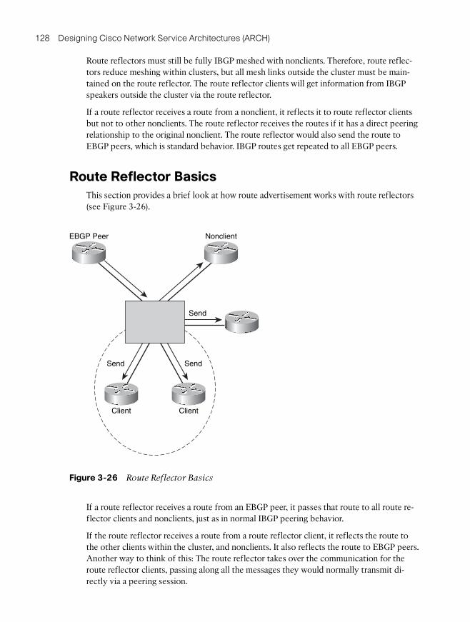
128 Designing Cisco Network Service Architectures (ARCH)
Route reflectors must still be fully IBGP meshed with nonclients. Therefore, route reflec-tors reduce meshing within clusters, but all mesh links outside the cluster must be main-tained on the route reflector. The route reflector clients will get information from IBGPspeakers outside the cluster via the route reflector.
If a route reflector receives a route from a nonclient, it reflects it to route reflector clientsbut not to other nonclients. The route reflector receives the routes if it has a direct peeringrelationship to the original nonclient. The route reflector would also send the route toEBGP peers, which is standard behavior. IBGP routes get repeated to all EBGP peers.
Route Reflector Basics
This section provides a brief look at how route advertisement works with route reflectors(see Figure 3-26).
If a route reflector receives a route from an EBGP peer, it passes that route to all route re-flector clients and nonclients, just as in normal IBGP peering behavior.
If the route reflector receives a route from a route reflector client, it reflects the route tothe other clients within the cluster, and nonclients. It also reflects the route to EBGP peers.Another way to think of this: The route reflector takes over the communication for theroute reflector clients, passing along all the messages they would normally transmit di-rectly via a peering session.
EBGP Peer Nonclient
Client Client
Send Send
Send
Figure 3-26 Route Reflector Basics

Chapter 3: Developing an Optimum Design for Layer 3 129
Scaling IBGP with Confederations
BGP confederations are another way of scaling IBGP. Their behavior is defined in RFC3065. Confederations insert information using the autonomous system path into BGProutes to prevent loops within an autonomous system. The basic idea with confederationsis to divide a normal BGP autonomous system into multiple sub-autonomous systems. Theouter or containing autonomous system is called the confederation autonomous system.This is all that is visible to the outside world.
Each of the inner autonomous systems is a smaller sub-autonomous system that uses a dif-ferent autonomous system number, typically chosen from the private autonomous systemnumber range of 64,512 through 65,534.
BGP Confederation Definitions
This topic defines terms used with confederations (see Figure 3-27).
Peers within the same sub-autonomous system are confederation internal peers.
AS65001
AS65002
AS50001
AS50004Confederation AS
Sub-AS
ConfederationInternal Peers
ConfederationExternal Peers
AS50003
Figure 3-27 Confederation Definitions

130 Designing Cisco Network Service Architectures (ARCH)
IBGP peers that are in a different sub-autonomous system are confederation external peers.
As IBGP information is passed around within a confederation autonomous system, the sub-autonomous system numbers are put into a confederation sequence, which works like anautonomous system path.
Confederation Basics
Route advertisement with confederations works similarly to that of route reflectors in thefollowing ways:
■ A route learned from an EBGP peer is advertised to all confederation external and in-ternal peers.
■ A route learned from a confederation internal peer is advertised to all confederationexternal peers, and also to EBGP peers.
■ A route learned from a confederation external peer is advertised to all confederationinternal peers, and to EBGP peers.
Another way to understand this is that IBGP between sub-autonomous systems acts likeEBGP. Private autonomous system numbers are used internally within the confederationautonomous system and removed from updates sent outside the confederation.
Confederations Reduce Meshing
Like route reflectors, confederations are used to reduce the amount of IBGP meshingneeded. Without route reflectors or confederation, IBGP requires a full mesh of peeringrelationships, as illustrated in Figure 3-28.
Note: Note that the IBGP does not require peers to be directly connected.
However, confederations can reduce meshing requirements, as shown in Figure 3-29.
Routers in different sub-autonomous systems do not peer with each other, except at sub-autonomous system borders. It is generally recommended to use two or three links be-tween sub-autonomous system borders. More links just consume CPU and memory in theborder routers.
When you use sub-autonomous systems for confederations, the meshing is restricted towithin the sub-autonomous systems, with some additional peering between sub-autonomoussystem border routers.
Route reflectors can be used within confederations to further reduce network complex-ity. Historically, service providers have not done this, but they are now starting to. Usingroute reflectors alleviates the need to fully mesh within a sub-autonomous system.

Chapter 3: Developing an Optimum Design for Layer 3 131
A
B C
E
J
G
H
D
F
Figure 3-28 IBGP Full-Mesh Peering
A
B C
E
J
G
H
D
F
Sub-AS Sub-AS
Figure 3-29 Confederations Reduce the Number of IBGP Peers

132 Designing Cisco Network Service Architectures (ARCH)
Deploying Confederations
In Figure 3-30, router B could be configured to set the BGP next hop to itself for adver-tisement to routers C and D. This is not normally done by IBGP routers. This would im-pose the constraint that routers C and D would need to have routes to the new next hop,router B.
Using this configuration breaks the confederation up from a next-hop perspective fromboth the IGP and BGP point of view. This scenario allows for more flexibility and scalingin very large networks. This deployment might make sense for very large organizationsthat support separate entities such as government organizations that have distinctbranches or divisions.
Using confederation sub-autonomous systems has other advantages. The IBGP policiescan differ internally within and between the sub-autonomous systems. In particular, multi-exit discriminator (MED) acceptance or stripping, local preference settings, route damp-ening, and so on can vary between sub-autonomous systems. In addition, policy controlscan be used on peerings between sub-autonomous systems.
This highlights some advantages of confederations. Confederations can ease the transitionin an acquisition or merger. The new network can be treated as another sub-autonomoussystem and keep its IGP. It can also keep its EBGP policies with its customers.
Sub-AS
A
B
C
D
Must Be Able to Reach B
neighbor c next–hop selfneighbor d next–hop self
OSPF
IS-IS
Sub-AS
Sub-AS EIGRP
Figure 3-30 Deploying Confederations
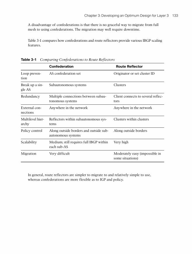
Chapter 3: Developing an Optimum Design for Layer 3 133
A disadvantage of confederations is that there is no graceful way to migrate from fullmesh to using confederations. The migration may well require downtime.
Table 3-1 compares how confederations and route reflectors provide various IBGP scalingfeatures.
In general, route reflectors are simpler to migrate to and relatively simple to use,whereas confederations are more flexible as to IGP and policy.
Table 3-1 Comparing Confederations to Route Reflectors
Confederation Route Reflector
Loop preven-tion
AS confederation set Originator or set cluster ID
Break up a sin-gle AS
Subautonomous systems Clusters
Redundancy Multiple connections between subau-tonomous systems
Client connects to several reflec-tors
External con-nections
Anywhere in the network Anywhere in the network
Multilevel hier-archy
Reflectors within subautonomous sys-tems
Clusters within clusters
Policy control Along outside borders and outside sub-autonomous systems
Along outside borders
Scalability Medium; still requires full IBGP withineach sub-AS
Very high
Migration Very difficult Moderately easy (impossible insome situations)

134 Designing Cisco Network Service Architectures (ARCH)
Summary
In summary, we’ve looked at elements of advanced routing design, and we also touched onthe merits of a well-planned IP addressing scheme. The IP addressing scheme is the foun-dation for greater efficiency in operating and maintaining a network. Without proper plan-ning in advance, networks might not be able to benefit from route summarization featuresinherent to many routing protocols.
The general advanced routing design discussion can be encapsulated in the following keypoints that were discussed previously:
■ Route summarization and default routing are important in scaling routing designs.
■ Route filtering can be used to manage traffic flows in the network, avoiding inappro-priate transit traffic and as a defense against inappropriate routing updates.
■ Redistribution can be useful for manipulating and managing routing updates, butneeds to be designed properly to prevent routing loops or other problems.
EIGRP converges quickly as long as it has a feasible successor. With no feasible successor,EIGRP sends queries out to its neighbors. To limit the scope of these queries, use routesummarization and filtering. By limiting EIGRP query scope, you can speed up EIGRPconvergence and increase stability. In addition, large numbers of neighbors should beavoided for any one router. Multiple autonomous systems may be used with EIGRP pro-viding that you understand that they do not directly limit EIGRP query scope. You woulduse them to support migration strategies, different administrative groups, or very largenetwork design.
OSPF scaling depends on summarization and controlling how much LSA flooding isneeded. Simple, stub, summarized designs scale most effectively. Several techniques speedup convergence for OSPF, including fast hellos, iSPF, and BFD.
Finally, IBGP requires a full mesh of all IBGP routers, but full-mesh peering does not scalegracefully. Route reflectors pass along routing information to and from their clients. Theroute reflector clients are relieved of the burden of most IBGP peering. Confederations al-low an autonomous system to be divided into sub-autonomous systems, where the sub-autonomous system border routers peer with each other and then pass along routes on be-half of the other sub-autonomous system routers. Confederation sequences are used toprevent information loops. Sub-autonomous systems can have different BGP polices fromeach other.
Key points to remember include the following:
■ IP address design allows for route summarization that supports network scaling, sta-bility, and fast convergence.
■ Route summarization, route filtering, and appropriate redistribution help minimizerouting information in the network.

Chapter 3: Developing an Optimum Design for Layer 3 135
■ EIGRP converges quickly as long as it has a feasible successor. Multiple autonomoussystems with EIGRP may be used, with care, to support special situations, includingmigration strategies and very large network design.
■ Simple, stub, summarized OSPF designs scale most effectively. Several techniquesspeed up convergence for OSPF, including fast hellos, iSPF, and BFD.
■ IBGP designs can be scaled using route reflectors to pass routing information to andfrom their clients and confederations to allow an autonomous system to be dividedinto sub-autonomous systems.
References
■ Cisco Systems, Inc. “Designing Large-Scale IP Internetworks,” at http://www.cisco.com/en/US/docs/internetworking/design/guide/nd2003.html
■ Cisco Systems, Inc. “Cisco IOS IP Routing Protocols Command Reference,” at http://www.cisco.com/en/US/docs/ios/iproute/command/reference/irp_book.html
■ The Internet Engineering Task Force. RFC 1793: Extending OSPF to Support Demand Circuits, at http://www.ietf.org/rfc/rfc1793.txt
■ The Internet Engineering Task Force. RFC 2328: OSPF Version 2, at http://www.ietf.org/rfc/rfc2328.txt
■ The Internet Engineering Task Force. RFC 2796: BGP Route Reflection—An Alterna-tive to Full Mesh IBGP, at http://www.ietf.org/rfc/rfc2796.txt
■ The Internet Engineering Task Force. RFC 3065: Autonomous System Confederationsfor BGP, at http://www.ietf.org/rfc/rfc3065.txt
■ The Internet Engineering Task Force. RFC 4136: OSPF Refresh and Flooding Reduction in Stable Topologies, at http://www.ietf.org/rfc/rfc4136.txt
Review Questions
Answer the following questions, and then refer to Appendix A, “Answers to Review Ques-tions,” for the answers.
1. Which two address blocks are summarizable? (Choose two.)
a. 172.16.20.0 to 172.16.27.0
b. 172.16.20.0 to 172.16.23.0
c. 10.16.0.0 to 10.31.0.0
d. 10.16.0.0 to 10.47.0.0
e. 10.96.0.0 to 10.159.0.0

136 Designing Cisco Network Service Architectures (ARCH)
2. Which two can bit-splitting techniques be used for? (Choose two.)
a. OSPF area design
b. Summarizable address blocks with convenient role-based subnets
c. Access list convergence
d. Detecting summarizable address blocks
e. Manual route summarization
3. Which is the recommended design approach?
a. Configure a static default route everywhere for predictability.
b. Configure static default routes using recursive routing for consistency.
c. Originate the default at the edge and redistribute it into dynamic routing.
d. Make the OSPF backbone area 0 stubby.
e. Do not use additional parameters with the originate default command.
4. Which two statements best describe redistribution? (Choose two.)
a. Redistribution works poorly with an arbitrary mix of routing protocols any-where.
b. Redistribution seldom requires route filters.
c. Redistribution is not useful after a merger.
d. Redistribution works well with a limited number of redistribution points.
e. Redistribution prevents summarization.
5. Select the best statement concerning EIGRP and OSPF routing design.
a. Routing design needs to be done most carefully for small networks.
b. OSPF should not be used for small networks.
c. Routing design needs to be done most carefully for large networks.
d. Route summarization must be used in all network designs.
e. OSPF works best with a full mesh.
6. Which three factors are the biggest influences on OSPF scalability? (Choose three.)
a. Flooding paths and redundancy
b. Amount of routing information in the OSPF area or routing domain
c. Number of routers capable of Cisco Express Forwarding
d. Number of adjacent neighbors
e. Other routing protocols in use

Chapter 3: Developing an Optimum Design for Layer 3 137
7. Which statement best describes basic IBGP?
a. IBGP is a link-state protocol.
b. IBGP requires a full mesh of peers because it has no other way to prevent loop-ing of routing information.
c. IBGP inherently handles all full-mesh scalability issues.
d. IBGP uses split horizoning to prevent looping of routing information.
e. IBGP uses the autonomous system path to prevent looping of routing information.
8. A route reflector reflects routes from a route reflector client to which three types ofIBGP routers? (Choose three.)
a. Nonclient routers
b. Sub-autonomous system members
c. Other route reflector client routers
d. EBGP peers
e. IBGP peers configured for EIGRP or OSPF routing