aga5802 spectroscopy iii - departamento de astronomiajorge/aga5802/2017_15_spectro3.pdf · aga5802...
TRANSCRIPT
AGA5802 Spectroscopy III
• Gratings
• Filtros (blocking order filters)
• Dichroics (espectrógrafos duplos)
• Linear dispersion of the spectrum
• Basic design of spectrographs
• Wavelength calibration lamps
• Grisms
Bibliography: To Measure the Sky, Kitchin, Lena and others
Prof. Jorge Meléndez
1

Dispersion by a diffraction grating (rede de difração)
2
Type -------- Capacity --- Track pitch how many per mm (1 mm = 103 mm)?
CD -------------- 0.7 Gb --- 1.6 μm 103um/1,6um = 625 lines/mm DVD ------------ 4.7 GB --- 0.74 μm 103um/0,74um = 1351 lines/mm Blu-ray Disc --- 25 GB ---- 0.32 μm 103um/0,74um = 3125 lines/mm

Rede de difração
3
While light
Microscopic picture of part of a difraction gratting of 1180 lines/mm © Gray, Stellar Photospheres, 3rd ed., Fig. 3.2 (p. 55)
+ -
s

Constructive interference in reflection gratings
4
When exiting the grating, the optical path of rays X & Y differ by Dt = AB – CD = s sin a - s sin r Dt = s sin a + s sin q
s sin a + s sin q = ml
a
s q
a r
r = 360 - q
a
a
r
r
AB = s sin a CD = s sin r
X Y
Constructive interference when Dt = m l , m = 0, ±1, ±2, …
Grating equation:
© To Measure the Sky
5
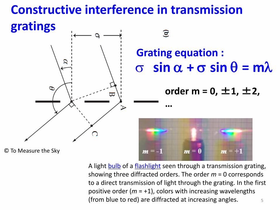
s sin a + s sin q = ml
order m = 0, ±1, ±2, …
Grating equation :
© To Measure the Sky
A light bulb of a flashlight seen through a transmission grating, showing three diffracted orders. The order m = 0 corresponds to a direct transmission of light through the grating. In the first positive order (m = +1), colors with increasing wavelengths (from blue to red) are diffracted at increasing angles.
Constructive interference in transmission gratings

Angular dispersion of a grating
6
s(sin a + sin q) = ml
sin q = ml/s - sin a
Differentiating the grating equation :
- cos q changes only slowly with l dispersion of the grating does not change much with wavelength
- Dispersion can be increased at higher orders

Resolution R of the grating
R = N m
N: number of lines across the grating
m: order
Example: grating 500 lines mm-1 in a 10mm grating at second order: R = 500 x 10 x 2 = 104
7

Angular overlap of grating orders
8 © To Measure the Sky
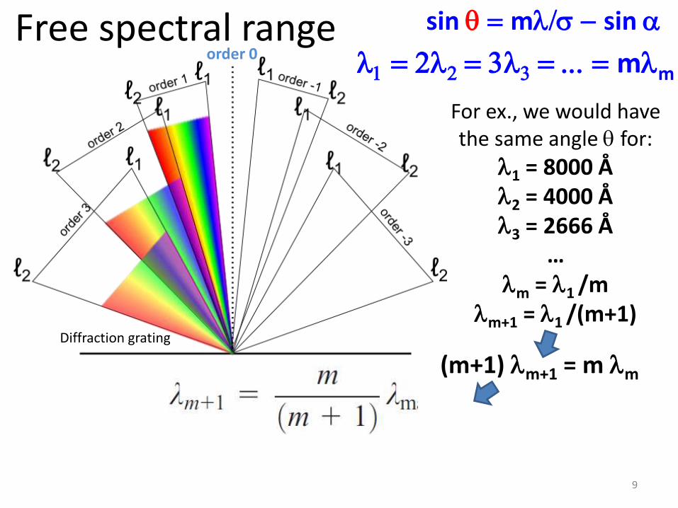
sin q = ml/s - sin a
q
l1 = 2l2 = 3l3 = ... = mlm
lm = l1 /m
Free spectral range
9
l1 = 2l2 = 3l3 = ... = mlm
For ex., we would have the same angle q for:
l1 = 8000 Å l2 = 4000 Å l3 = 2666 Å
… lm = l1 /m
lm+1 = l1 /(m+1)
order 0
(m+1) lm+1 = m lm
sin q = ml/s - sin a
Diffraction grating

Practical coverage of an order
10
l1 = 2l2 = 3l3 = ... = mlm In order to observe up to l = lmax, the l of the next
order that would affect the results is:
Diffraction grating
order 0
For example, for lmax = 9000 Å at 1st order, we will have contamination for l = 4500 Å of the 2nd order. Introducing a
filter to block l < 4500 Å we can observe in 4500-9000 Å.
sin q = ml/s - sin a
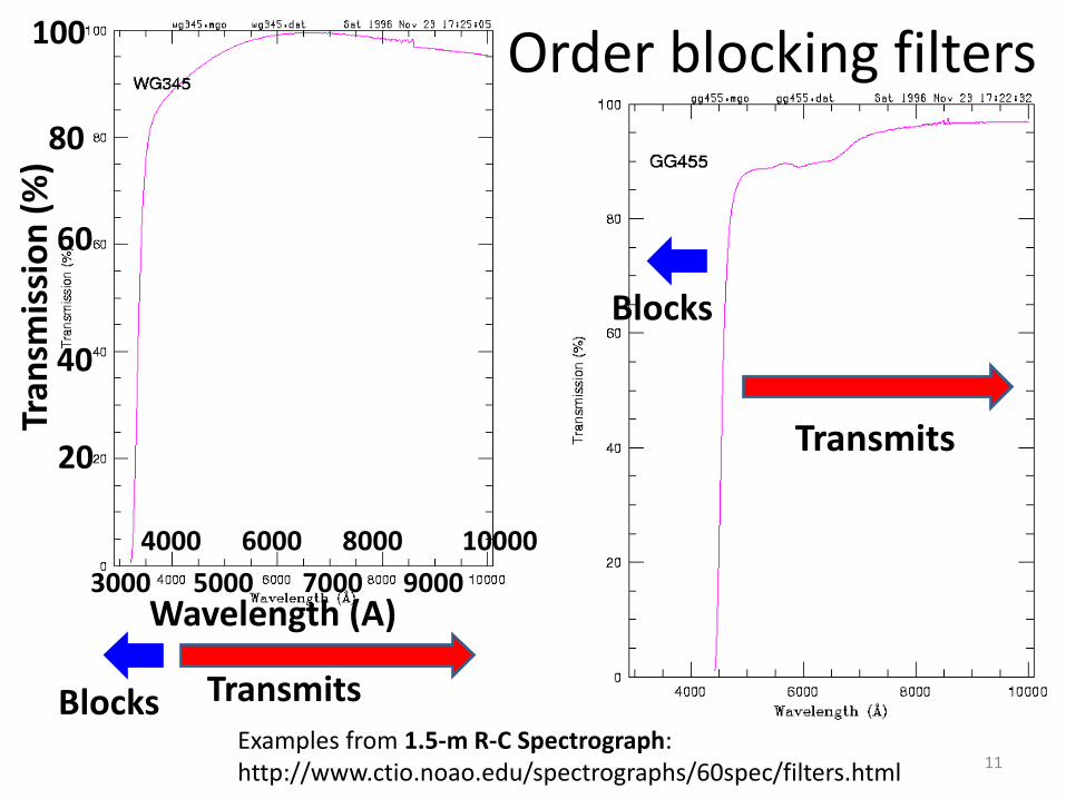
Order blocking filters
11 Examples from 1.5-m R-C Spectrograph: http://www.ctio.noao.edu/spectrographs/60spec/filters.html
100 Tr
ansm
issi
on
(%
)
Wavelength (A)
4000
Blocks Transmits
6000 8000 10000
3000 5000 7000 9000
80
60
40
20 Transmits
Blocks
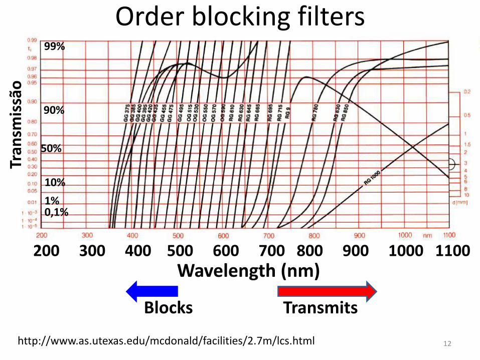
Order blocking filters
12 http://www.as.utexas.edu/mcdonald/facilities/2.7m/lcs.html
99%
90%
50%
10%
1%
Tran
smis
são
Wavelength (nm) 200 300 400 500 600 700 800 900 1000 1100
0,1%
Blocks Transmits
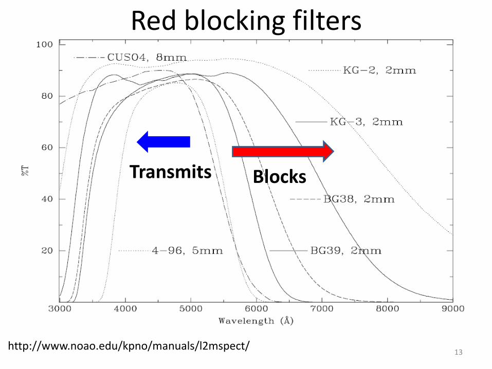
Red blocking filters
13
Blocks Transmits
http://www.noao.edu/kpno/manuals/l2mspect/

Free spectral range (DlFSR)
14
The free spectral range (FSR) is the coverage in
l that is not blocked
order 0
For example, for lmax = 900nm at 1st order we would have DlFSR = 450nm we can observe in the range 450 - 900 nm
Lambda minimum:
Diffraction grating

Blazed gratings (redes com blazing)
15 © Kitchin
Disadvantage: much light is lost at order 0 and in other orders. In gratings with blazing the facet of each ruling has an angle, concentrating most of the light in a given order

16
Blazed gratings Best tilt to concentrate all light in an order:
© To Measure the Sky
In the book “To Measure the Sky” is a, but is wrong

Blazing’s efficiency
The efficiency is maximum at lb, with the efficiency decreasing to 50% at:
•lmin= 2/3 lb
•lmax= 3/2 lb
Example, lb = 6000 Å we can cover with efficiency > 50% (max efficiency): 4000 – 9000 Å.
17

Example
18
Diffraction
Gratings available for LCS
grating number
lines/mm blaze (Å)
effective blaze (Å)
dispersion l/ one-pixel Dl
(TI1 CCD)
40 300 4200 3900 550
41 300 7500 6000 550
42 300 10000 9200 550
43 600 4000 3700 1100
44 600 7500 6900 1100
45 600 10000 9200 1100
46 1200 4000 3700 2200
47 1200 6000 5500 2200
48 1200 7500 6900 2200
Gratings are blazed for use in first order.
http://www.as.utexas.edu/mcdonald/facilities/2.7m/lcs.html
Important points 1. Due to blazing, the grating is optimized for a particular
region of the spectrum (although you can use several gratings, of course).
2. Due to order overlapping, the spectral coverage is limited
3. Different elements (e.g. CCD) could be optimized for a given spectral region
Is complicated to cover all the optical spectrum (300-1000nm) with only 1 spectrograph
19
“Double spectrograph”

Double spectrograph (2 arms)
20
Double spectrograph for the Palomar telescope (5 meters). RED side covers 550-1000 nm BLUE side is optimized for 300-550 nm
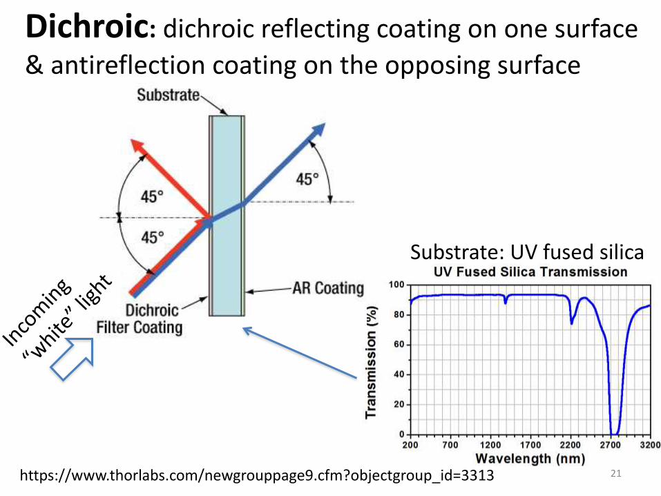
Dichroic: dichroic reflecting coating on one surface
& antireflection coating on the opposing surface
21 https://www.thorlabs.com/newgrouppage9.cfm?objectgroup_id=3313
Substrate: UV fused silica
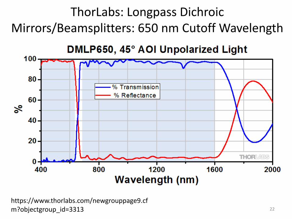
ThorLabs: Longpass Dichroic Mirrors/Beamsplitters: 650 nm Cutoff Wavelength
22
https://www.thorlabs.com/newgrouppage9.cfm?objectgroup_id=3313

Dichroic: light into different l double spectrograph
refletem em um intervalo espectral e transmitem em outro
23
Example : Palomar Double Spectrograph
3000 4000 5000 6000 7000 8000 9000 10000
Wavelength (A)
Tran
smit
tan
ce (
%)
100
80
60
40
20
0
Reflects Transmits

Gratings for the Palomar double spectrograph
1st Order Useful Range (Å) Red Camera Blue Camera
lines/mm Blaze (Å) (to blaze 1/2-
intensity) Dispersion
(Å/mm) Dispersion
(Å/mm)
158 [a] 7560 5000-11300 201 1st [c] 135 2nd [d]
300 [b] 3990 2700-6000 - 140 1st
316 [a] 7150 4800-10700 102 1st -
600 [b] 3780 2500-5700 - 71 1st
600 [a] 9500 6300-14300 54 1st -
1200 [b] 4700 3100-7100 - 36 1st
1200 7100 4700-10700 27 1st 36 1st
1200 9400 6300-14100 26 1st 35 1st
24
(F) GRATING SPECS (lines/mm, blaze, dispersion)
NOTE: "Useful Range" gives the wavelength limits at which diffracted intensity drops to 1/2 of its peak value (2/3 and 3/2 of the blaze wavelength, by a common rule of thumb). [a] silver coating...can be used only longward of 3500 Å. [b] can be used only in blue spectrograph. [c] first order. [d] second order.
R ~ 1,000 to 10,000

Linear dispersion of the spectrum (valid for both prisms & gratings)
25
Angular dispersion of prism Angular dispersion of grating

Linear dispersion dx/dl
26
CCD
Linear dispersion

Example for prism (a = 60O)
27
Typical value for dq/dl = 1,39 x 10⁷ Om-1
Compute dq for dl = 1 Å
dq = 1,39 x 10⁷ O m-1 x 10⁻¹⁰ m
dq = 1,39 x 10⁻³ O = 5 arcsec
Linear dispersion on CCD ?

Linear dispersion dx/dl
28
dq/ dl = 1,39 x 10⁷ Om-1
CCD Linear dispersion:
1 degree = 0,0174 radians dq/ dl = 2,426 x 10 5 radians m-1
dx/dl = f2 dq/ dl = 0,5m x 2,426 x 10 5 radians m-1 = 1,21 x 10⁵
dx = dl x 1,21 x 105 = 1,21 x 105 x 2Å = 2,42 x 105 x 10-4mm dx = 24 mm. If pixel is 12 mm 2 pixels
Example for f2 = 50 cm Estimate dx in dλ=2Å. How many 12-mm pixels ?
Typical value for dq/dl = 1,39 x 10⁷ Om-1
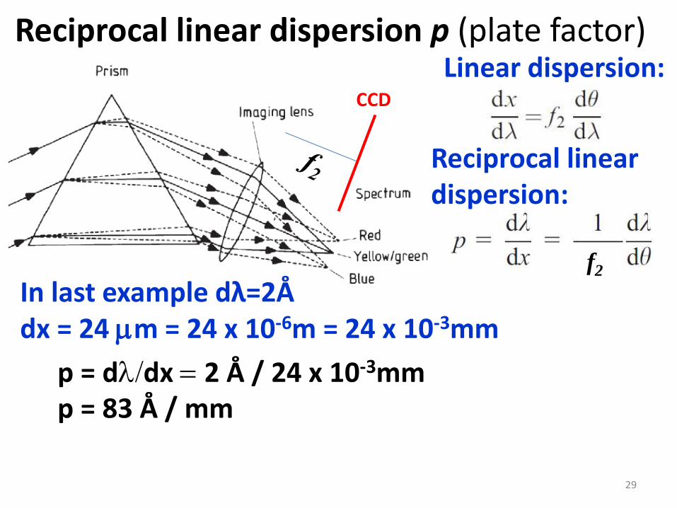
Reciprocal linear dispersion p (plate factor)
29
CCD
Linear dispersion:
p = dl/dx = 2 Å / 24 x 10-3mm p = 83 Å / mm
In last example dλ=2Å dx = 24 mm = 24 x 10-6m = 24 x 10-3mm
Reciprocal linear dispersion:
f2

High dispersion (high resolution) and low dispersion (low resolution) spectroscopy
high dispersion (spectroscopy) means:
Large linear dispersion
or small plate factor for ex.: p ~ 5Å/mm
low dispersion (spectroscopy) means:
Low linear dispersion, i.e. large plate factor, por ex.: p ~ 100 Å/mm
30

Basic design of spectrographs
31
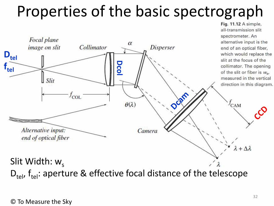
Properties of the basic spectrograph
32
© To Measure the Sky
Dco
l Slit Width: ws
Dtel, ftel: aperture & effective focal distance of the telescope
Dtel
ftel

Angular size of the slit on the sky
33
© To Measure the Sky
Dco
l
The angular size of the slit on the sky is :
Dtel
ftel
Slit Width: ws
ws could also be the diameter of the fiber
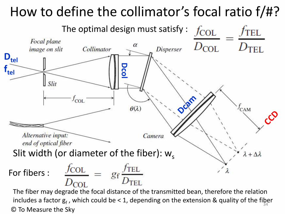
How to define the collimator’s focal ratio f/#?
34
© To Measure the Sky
Dco
l
Dtel
ftel
Slit width (or diameter of the fiber): ws
The optimal design must satisfy :
For fibers :
The fiber may degrade the focal distance of the transmitted bean, therefore the relation includes a factor gf , which could be < 1, depending on the extension & quality of the fiber
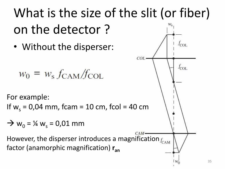
What is the size of the slit (or fiber) on the detector ? • Without the disperser:
35
For example: If ws = 0,04 mm, fcam = 10 cm, fcol = 40 cm
w0 = ¼ ws = 0,01 mm
However, the disperser introduces a magnification factor (anamorphic magnification) ran

What is the size of the slit or fiber on the detector (w0)?
36
© To Measure the Sky
Dco
l
Dtel
ftel
ran = cos a/ cos q = DCOL / DCAM
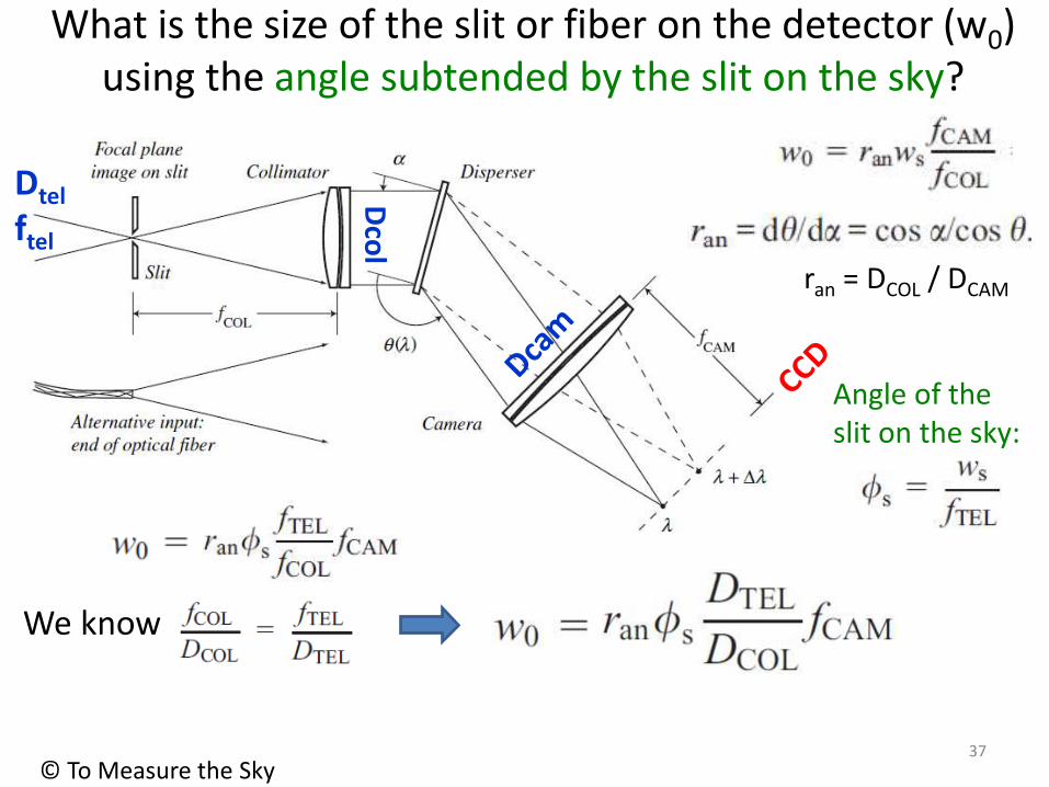
What is the size of the slit or fiber on the detector (w0) using the angle subtended by the slit on the sky?
37
© To Measure the Sky
Dco
l
Dtel
ftel
Angle of the slit on the sky:
We know
ran = DCOL / DCAM

Resolution dl0 of the spectrograph
38
© To Measure the Sky
Dco
l
Dtel
ftel
Using:
dl0 = w0 p
ran = DCOL / DCAM
Other forms :

Resolving power R (= l/dl0) of the spectrograph
39
© To Measure the Sky
Dco
l
Dtel
ftel
Ideally the angle of the slit on the sky should be < seeing:
However, if seeing is lower than use for R
Actually, we can have different slit sizes

Can we use a spectrograph designed for a different telescope?
40
PHOENIX INFRARED HIGH-RESOLUTION SPECTROGRAPH At the 2.1 m the 4 pixel slit is 1.4 arcsec wide. At the 4 m it is 0.7 arcsec wide
http://www.noao.edu/kpno/phoenix/

Resolution vs. slit width ws
• EXAMPLE with PHOENIX spectrograph, slits available: 2 pixel (54 mm), 3 pixel (81 mm), and 4 pixel (107 mm)
• ws = 4 pixels on detector R = 50 000
• ws = 2 pixels on detector should be R = 100 000, but due to problems in the optics it is actually R = 75 000
• ws = 3 pixels on detector should be R = 75 000, but it is actually R = 63 000
41
Phoenix spectrograph at Kitt Peak (2m & 4m)
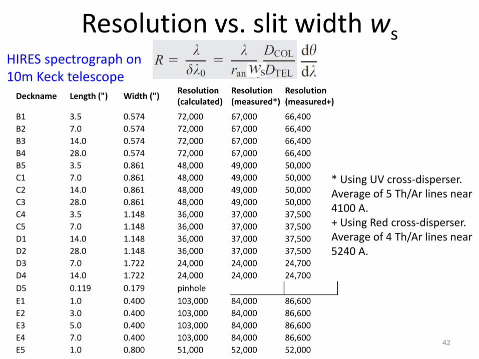
Resolution vs. slit width ws
42
Deckname Length (") Width (") Resolution (calculated)
Resolution (measured*)
Resolution (measured+)
B1 3.5 0.574 72,000 67,000 66,400
B2 7.0 0.574 72,000 67,000 66,400
B3 14.0 0.574 72,000 67,000 66,400
B4 28.0 0.574 72,000 67,000 66,400
B5 3.5 0.861 48,000 49,000 50,000
C1 7.0 0.861 48,000 49,000 50,000
C2 14.0 0.861 48,000 49,000 50,000
C3 28.0 0.861 48,000 49,000 50,000
C4 3.5 1.148 36,000 37,000 37,500
C5 7.0 1.148 36,000 37,000 37,500
D1 14.0 1.148 36,000 37,000 37,500
D2 28.0 1.148 36,000 37,000 37,500
D3 7.0 1.722 24,000 24,000 24,700
D4 14.0 1.722 24,000 24,000 24,700
D5 0.119 0.179 pinhole
E1 1.0 0.400 103,000 84,000 86,600
E2 3.0 0.400 103,000 84,000 86,600
E3 5.0 0.400 103,000 84,000 86,600
E4 7.0 0.400 103,000 84,000 86,600
E5 1.0 0.800 51,000 52,000 52,000
* Using UV cross-disperser. Average of 5 Th/Ar lines near 4100 A. + Using Red cross-disperser. Average of 4 Th/Ar lines near 5240 A.
HIRES spectrograph on 10m Keck telescope
Res
olu
tio
n v
s. s
lit w
idth
43
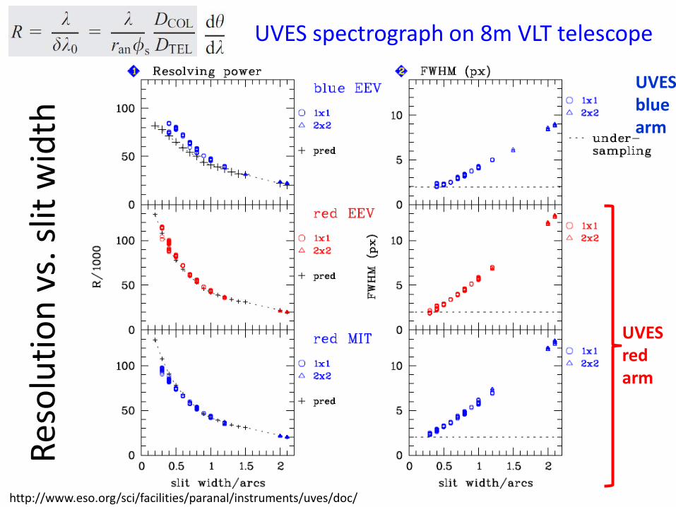
UVES spectrograph on 8m VLT telescope
http://www.eso.org/sci/facilities/paranal/instruments/uves/doc/
UVES red arm
UVES blue arm

Resolution vs. slit width ws - Coudé OPD
44

Calibration lamps (a.k.a. arcs) (to calibrate wavelength)
45 http://mthamilton.ucolick.org/techdocs/instruments/nickel_spect/arcSpectra/
Pixel number
l =
58
52
,49
Å
l =
72
45
,17
Å
l =
84
95
,36
Å
NEON arc (observed with a 600 lines/mm grism)
0 200 400 800 1000 1200
Flu
x
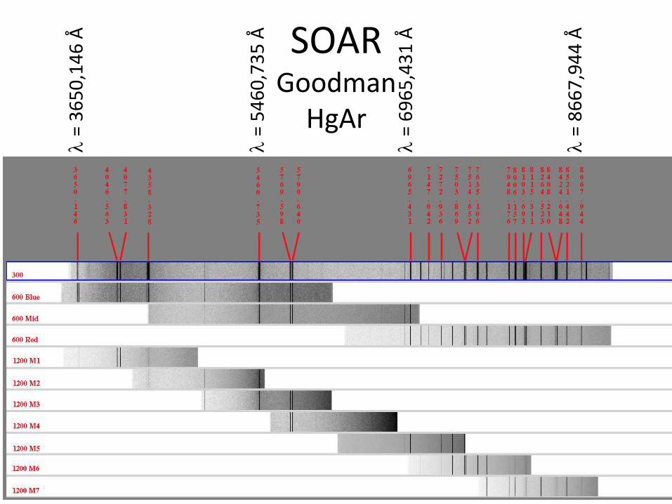
SOAR Goodman
HgAr
46
l =
36
50
,14
6 Å
l =
86
67
,94
4 Å
l =
69
65
,43
1 Å
l =
54
60
,73
5 Å
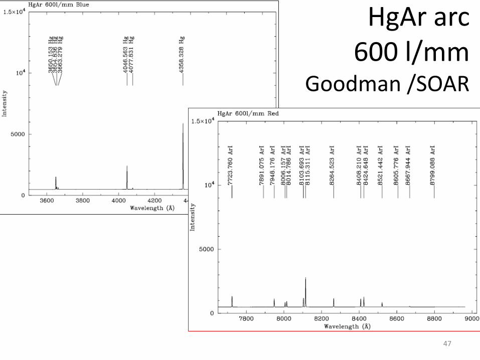
HgAr arc 600 l/mm
Goodman /SOAR
47

Grism = Grating + Prism
48
The deviation of the light beam by the prism is compensated by the deviation due to the grating light passes straight through
The instrument could serve as an imager, removing the grism from the optical path
Grisms
CCD
Camera lens
Collimator
http://mthamilton.ucolick.org/techdocs/instruments/nickel_spect/hw_overview/
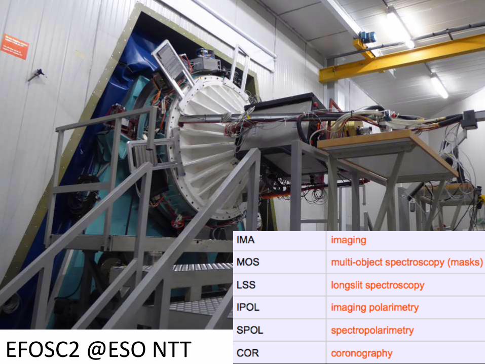
49 EFOSC2 @ESO NTT

50
.@ISaviane

51
Punching EFOSC2 MOS Plates

52

X-Shooter @ESO VLT
53

54

55
56
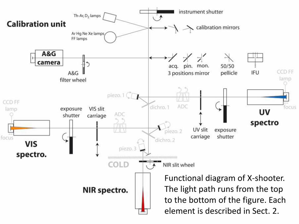
Functional diagram of X-shooter. The light path runs from the top to the bottom of the figure. Each element is described in Sect. 2.

57
58
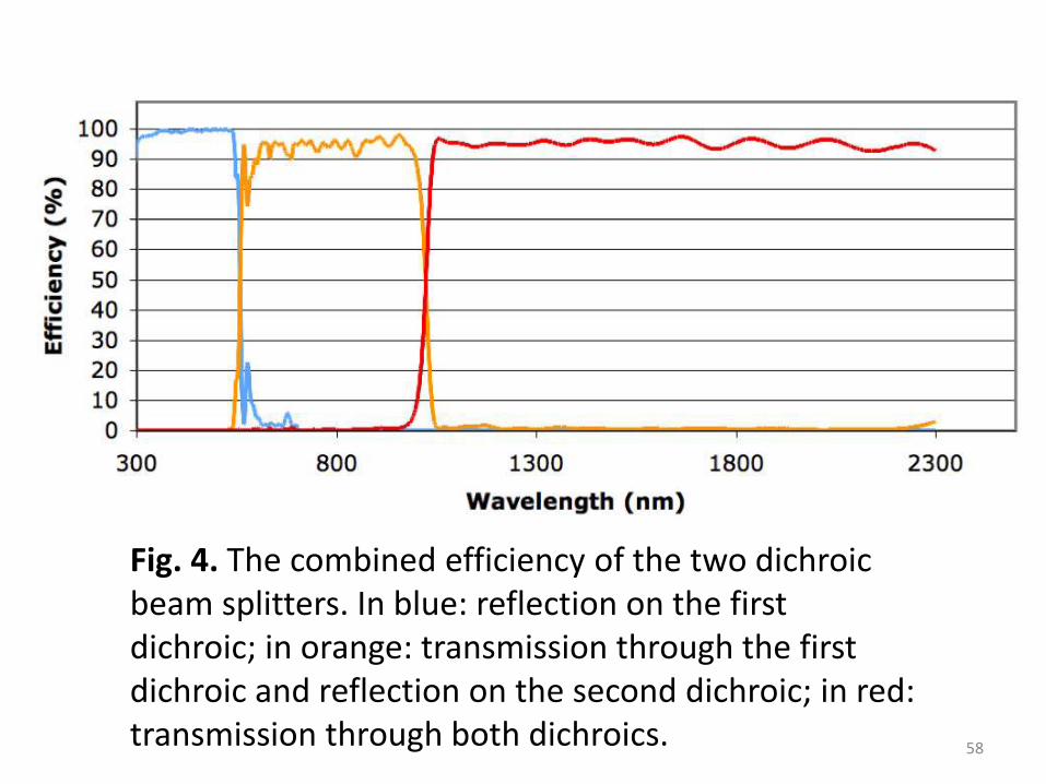
Fig. 4. The combined efficiency of the two dichroic beam splitters. In blue: reflection on the first dichroic; in orange: transmission through the first dichroic and reflection on the second dichroic; in red: transmission through both dichroics.
59

60

61

62
However, as Gemini staff, we have no vested interest in building an instrument, so our chief purpose is to encourage further debate and out-of-the-box thinking.

63