agenda and objectives - trane · agenda and objectives trane engineers newsletter live series...
TRANSCRIPT

Agenda and Objectives
Trane Engineers Newsletter Live Series
Central Geothermal System Design and Control
Many people are familiar with geothermal heat pump systems, using small, "geothermal" heat pumps, distributed
throughout the building, that are coupled with a ground source heat exchanger. These systems operate very efficiently
since heat rejected to the ground loop in the summer is stored and extracted in the winter. Today, project teams are also
considering central geothermal systems consisting of one or two chillers coupled with a closed, geothermal loop which
exchanges heat with the earth. Such systems offer high energy efficiency, with the additional benefit of centralized
maintenance, acoustic advantages, and airside flexibility. This program discusses benefits, challenges, design,
and control of central geothermal systems.
Learning objectives:
1. Identify the key differentiators from distributed systems.
2. Summarize the design and operation of central geothermal systems
3. Explain how the system offers airside system flexibility.
4. Identify key design considerations for central geothermal systems.
5. Summarize the energy analysis results comparing central geothermal systems, 90.1 baseline and alternative systems
Agenda:
1) Overview
a) Compare to distributed systems
2) System discussion
a) Central system configuration
b) Central system operation
c) Central system controls
d) Key design issues (redundancy, glycol, hybrid sizing etc)
3) Equipment performance requirements
a) Temps
b) Cooling/heating flexibility
4) Energy performance/TRACE™ 700
a) Assumptions
b) Study results
5) Summary
Agenda_APPCMC039.ai 1 6/12/2014 1:41:13 PM

Presenters
Trane Engineers Newsletter Live Series
Central Geothermal System Design and Control (2010)
Lee Cline | senior principal systems engineer | Trane Lee is an engineer in the Systems Engineering Department with over 29 years experience at Trane. His career at Trane started as a factory service engineer for heavy refrigeration, helping to introduce the CVHE centrifugal chiller with electronic controls to the industry. Following that Lee was a member of the team that kicked off the microelectronic building automation and Integrated Comfort Systems controls – ICS - offering at Trane. He continues to push new unit and system control and optimization concepts into the industry. As a Systems Engineer Lee also has the opportunity to discuss HVAC system application and control with owners, engineers and contractors on a daily basis. Lee has a Bachelors degree in Mechanical Engineering from Michigan Technological University. He is a member of ASHRAE and a Registered Professional Engineer in the State of Wisconsin. Eric Sturm | C.D.S. marketing engineer | Trane Eric joined Trane in 2006. He is responsible for driving development of the TRACE software program including compliance with ASHRAE Standards 90.1 and 140. Eric’s primary responsibility is assisting customers of Trane's HVAC system design and analysis applications including TRACE 700 and System Analyzer. In addition Eric is a member of Trane's Advanced Engineering Services, providing building simulations for various projects. Eric earned his BSME from University of Wisconsin-Platteville and is a member of ASHRAE.
Mick Schwedler | manager, applications engineering | Trane Mick joined Trane in 1982 With expertise in system optimization and control, and in chilled-water system design, Mick’s primary responsibility is to help designers properly apply Trane products and systems through one-on-one support, technical publications, and seminars. Mick is a past Chair of SSPC 90.1. Mick holds a B.S. and M.S. degree in mechanical engineering.and he is a registered professional engineer in the State of Wisconsin.
Brian Fiegen, | global systems applications leader| Trane Brian is the Manager of Systems Engineering (Applications Engineering, Systems Engineering, and C.D.S.). Brian joined Trane in 1983, and has held a number of marketing and management positions throughout his career. He has been involved with product development and promotion of air handling and distribution products, systems, and controls throughout much of that time. Brian is deeply involved in managing Trane’s position on key industry issues such as IAQ and sustainable construction. Brian earned his BSME from South Dakota School of Mines and Technology in Rapid City, SD.
Biographies_APPCMC039.ai 1 6/12/2014 1:35:43 PM

Central Geothermal SystemDesign and Control© 2010 Trane, a business of Ingersoll Rand. 1
Engineers Newsletter Live
Central Geothermal System Design and Control
© 2010 Trane, a business of Ingersoll-Rand
This program is registered with the AIA/CES and USGBC for LEED® continuing professional education. 1.5 CEs earned on completion of this program will be reported to CES Records for AIA members.
Continuing Education Credit

Central Geothermal SystemDesign and Control© 2010 Trane, a business of Ingersoll Rand. 2
Engineers Newsletter Live
© 2010 Trane, a business of Ingersoll-Rand
Copyrighted Materials
This presentation is protected by U.S. and international copyright laws. Reproduction, distribution, display, and use of the presentation without written permission of Trane is prohibited.
© 2010 Trane, a business of Ingersoll-Rand. All rights reserved.
© 2010 Trane, a business of Ingersoll-Rand
central geothermal systems
Today’s Topics
Overview of central geothermal systems • Comparison to distributed systems
Design and control• Configuration
• Operation
• Controls
Design considerations
Equipment performance requirements
Energy performance

Central Geothermal SystemDesign and Control© 2010 Trane, a business of Ingersoll Rand. 3
Engineers Newsletter Live
© 2010 Trane, a business of Ingersoll-Rand
Today’s Presenters
Brian Fiegen
Global Systems Applications Leader
Eric Sturm
C.D.S. Marketing Engineer
© 2010 Trane, a business of Ingersoll-Rand
Today’s Presenters
Mick Schwedler
Applications Engineering Manager
Lee Cline
Systems Engineer
Central Geothermal SystemDesign and Control© 2010 Trane, a business of Ingersoll Rand. 4
Engineers Newsletter Live
© 2010 Trane, a business of Ingersoll-Rand
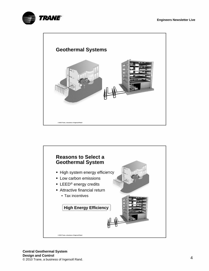
Geothermal Systems
© 2010 Trane, a business of Ingersoll-Rand
Reasons to Select a Geothermal System
High system energy efficiency
Low carbon emissions
LEED® energy credits
Attractive financial return• Tax incentives
High Energy Efficiency

Central Geothermal SystemDesign and Control© 2010 Trane, a business of Ingersoll Rand. 5
Engineers Newsletter Live
© 2010 Trane, a business of Ingersoll-Rand
What Makes Geothermal Systems Efficient?
Earth temperatures• Cool heat sink when cooling• Warm heat source when heating
Heat-pump based heating Heat-recovery system
• Share energy between heating and cooling zones• Store heat from cooling season• Extract heat in the heating season
Efficient equipment• High-efficiency heat pumps
© 2010 Trane, a business of Ingersoll-Rand
Distributed Heat Pump System
horizontalheat pump
dedicated outdoor air unit
ventilationduct system

Central Geothermal SystemDesign and Control© 2010 Trane, a business of Ingersoll Rand. 6
Engineers Newsletter Live
© 2010 Trane, a business of Ingersoll-Rand
Distributed Geothermal System
heatpumps
water pumpsvertical-loop groundheat exchanger (borefield)
WSHPs
Dedicated outdoor air units
Optional fluid cooler
Water pumps
Geo heat exchanger
© 2010 Trane, a business of Ingersoll-Rand
waterdistributionloop
air separator
pipingDistributed Geothermal System

Central Geothermal SystemDesign and Control© 2010 Trane, a business of Ingersoll Rand. 7
Engineers Newsletter Live
© 2010 Trane, a business of Ingersoll-Rand
Advantages• Limited floor space requirements• Easy to self-service • Isolated impact of equipment failure• Capacity can be added • Simple piping design
Disadvantages• In-space service and maintenance• Distributed service and maintenance• Acoustics• Complex dedicated outdoor air systems• Mixing related energy efficiency loss (entropy)• Limited air filtration options
Distributed Geothermal System
© 2010 Trane, a business of Ingersoll-Rand
Central Geothermal System

Central Geothermal SystemDesign and Control© 2010 Trane, a business of Ingersoll Rand. 8
Engineers Newsletter Live
© 2010 Trane, a business of Ingersoll-Rand
Central Geothermal System
Heat recovery chillers (chiller/heaters) provide heating and cooling• Hydronic four pipe
Central air handlers VAV terminals Auxiliary boilers Water pumps
© 2010 Trane, a business of Ingersoll-Rand
pipingCentral Geothermal Chiller/Heater System
To borefield
From borefield
coolingload
On Heat
On Cool
PLc
PC PLe
M MM
M
M M
A
cond
evap
PH
VCC
VEC
B
cond
evap
heatingload
PB

Central Geothermal SystemDesign and Control© 2010 Trane, a business of Ingersoll Rand. 9
Engineers Newsletter Live
© 2010 Trane, a business of Ingersoll-Rand
Bidirectional Cascade Central Geothermal System
Disadvantages• Requires MER space• Requires a chiller technician to service the central
plant• Redundancy must be designed• Capacity addition
© 2010 Trane, a business of Ingersoll-Rand
Advantages• Service and maintenance occurs in an equipment
room• Service and maintenance is centralized• Acoustics (equipment away from space)• Air economizer integrates into air distribution system• Efficient cascading of simultaneous energy streams• Air filtration flexibility
Bidirectional Cascade Central Geothermal System

Central Geothermal SystemDesign and Control© 2010 Trane, a business of Ingersoll Rand. 10
Engineers Newsletter Live
© 2010 Trane, a business of Ingersoll-Rand
Geothermal Systems
An HVAC system with compelling benefits including energy efficiency
Most geothermal systems utilize distributed near space heat pumps for heating and cooling
Central geothermal systems are an alternative to traditional distributed geothermal systems• Enables centralized service and maintenance
• Premium efficiency
• Improved acoustics and IAQ
System Configuration
Central Geothermal System Design and Control

Central Geothermal SystemDesign and Control© 2010 Trane, a business of Ingersoll Rand. 11
Engineers Newsletter Live
© 2010 Trane, a business of Ingersoll-Rand
Central Geothermal System
© 2010 Trane, a business of Ingersoll-Rand
bidirectional cascade
Operation & Control
Goal:
CGS concept understanding• Where does the water go?
Operating modes• Cooling only mode
• Heating only mode
• Simultaneous heating/cooling modes

Central Geothermal SystemDesign and Control© 2010 Trane, a business of Ingersoll Rand. 12
Engineers Newsletter Live
© 2010 Trane, a business of Ingersoll-Rand
Central Geothermal System
To borefield
From borefield
coolingload
On Heat
On Cool
PLc
PC PLe
M MM
M
M M
A
cond
evap
PH
VCC
VEC
B
cond
evap
heatingload
PB
© 2010 Trane, a business of Ingersoll-Rand
Central Geothermal SystemFluid Flow
Three loops
• Borefield
• Condenser energy transfer loop
• Evaporator energy transfer loop
Two “energy cascade” paths
• Chiller condenser to heater evaporator
• Heater evaporator to chiller condenser
• Result in more efficient system operation

Central Geothermal SystemDesign and Control© 2010 Trane, a business of Ingersoll Rand. 13
Engineers Newsletter Live
© 2010 Trane, a business of Ingersoll-Rand
Chilled Water to Building Loads
On Cool
coolingload
PC
M
A
cond
evapCooling system
© 2010 Trane, a business of Ingersoll-Rand
Hot Water to Building Loads
On Cool
coolingload
PC
M
A
cond
evap
On Heat
M heatingload
PH
B
cond
evap
Heating system

Central Geothermal SystemDesign and Control© 2010 Trane, a business of Ingersoll Rand. 14
Engineers Newsletter Live
© 2010 Trane, a business of Ingersoll-Rand
Borefield loop
On Cool
coolingload
PC
M
A
cond
evap
From borefield
On Heat
M heatingload
PH
B
cond
evap
To borefield PB
© 2010 Trane, a business of Ingersoll-Rand
Condenser Energy Transfer Loop
On Cool
coolingload
PC
M
From borefield
PLc
M
A
cond
evap
Off Heat
M heatingload
PH
B
cond
evap
Condenser energy transfer pump
To borefield PB

Central Geothermal SystemDesign and Control© 2010 Trane, a business of Ingersoll Rand. 15
Engineers Newsletter Live
© 2010 Trane, a business of Ingersoll-Rand
Off Cool
coolingload
PC
M
A
cond
evap
Evaporator Energy Transfer Loop
M
From borefield
PLe
On Heat
M heatingload
PH
B
cond
evap
Evaporator energy transfer pump
To borefield PB
© 2010 Trane, a business of Ingersoll-Rand
Two Energy Cascade Paths
To borefield
From borefield
coolingload
On Cool
PLc
PC PLe
M
M M
A
cond
evap
On Heat
M
PH
B
cond
evap
heatingload
Energy Cascade – condenser to evaporator
Energy Cascade – evaporator to condenser
PB

Central Geothermal SystemDesign and Control© 2010 Trane, a business of Ingersoll Rand. 16
Engineers Newsletter Live
© 2010 Trane, a business of Ingersoll-Rand
Water Flow
Three loops
• Borefield
• Condenser energy transfer loop
• Evaporator energy transfer loop
Two “energy cascade” paths
• Chiller condenser to heater evaporator
• Heater evaporator to chiller condenser
• Result in more efficient system operation
Operation and Control:Cooling Only
Central Geothermal System Design and Control

Central Geothermal SystemDesign and Control© 2010 Trane, a business of Ingersoll Rand. 17
Engineers Newsletter Live
© 2010 Trane, a business of Ingersoll-Rand
M
Cooling Only Mode Operation
Heat is rejected to the borefield
From borefield
PLc
On Cool
coolingload
PC
M
A
cond
evap
On Cool
coolingload
PC
M
A
cond
evap
To borefield PB
© 2010 Trane, a business of Ingersoll-Rand
Multiple Chillers in Cooling Mode
From borefield
PLc
M
On Cool
coolingload
PC
M
A
cond
evap
On Cool
coolingload
PC
M
A
cond
evap
M
M
On Cool
A
cond
evap
M
M
On Cool
A
cond
evap
To borefield PB

Central Geothermal SystemDesign and Control© 2010 Trane, a business of Ingersoll Rand. 18
Engineers Newsletter Live
© 2010 Trane, a business of Ingersoll-Rand
bidirectional cascade control
Plant Control
Must respond to:
Cooling load
Heating load
Systems limits
Unit operating limits
Pump energy consumption
Pump VFDs
© 2010 Trane, a business of Ingersoll-Rand
SYS-APM009-EN

Central Geothermal SystemDesign and Control© 2010 Trane, a business of Ingersoll Rand. 19
Engineers Newsletter Live
© 2010 Trane, a business of Ingersoll-Rand
bidirectional cascade control
Cooling Only Mode
Condenser Energy Transfer Loop pump (PLc) controlled to maintain design chiller condenser water flow rate
Heat is rejected to the borefield
Borefield pump (PB) controlled to maintain entering chiller condenser water temperature
To borefield
From borefield
coolingload
On Cool
On Cool
PLc
PC
M MM
M
M M
A
cond
evap
B
cond
evap
Chilled water system is controlled to meet the building cooling load
PB
© 2010 Trane, a business of Ingersoll-Rand
To borefield
From borefield
coolingload
OffOff
PLc
PC
M MM
M
M M
A
cond
evap
B
cond
evap
1. Enable Chilled
Water Loop Operation
PB
bidirectional cascade control
Cooling Only Mode

Central Geothermal SystemDesign and Control© 2010 Trane, a business of Ingersoll Rand. 20
Engineers Newsletter Live
© 2010 Trane, a business of Ingersoll-Rand
To borefield
From borefield
coolingload
OffOff
PLc
PC
M MM
M
M M
A
cond
evap
B
cond
evap
PCVFD
DPT3
2. Cond Energy
Trans Loop Pump PLc /
PLcVFD
Modulates based on
DPT3
PB
bidirectional cascade control
Cooling Only Mode
© 2010 Trane, a business of Ingersoll-Rand
Off
To borefield
From borefield
coolingload
PLc
PC
M MM
M
M M
A
cond
evap
B
cond
evap
PCVFD
DPT3
3. Chlr/Htr Operating in
Cooling Mode
Controls to Leaving Chilled Water
Setpoint
On Cool
OffA
cond
evap
PB
bidirectional cascade control
Cooling Only Mode

Central Geothermal SystemDesign and Control© 2010 Trane, a business of Ingersoll Rand. 21
Engineers Newsletter Live
© 2010 Trane, a business of Ingersoll-Rand
Off
To borefield
From borefield
coolingload
PLc
PC
M MM
M
M M
A
cond
evap
B
cond
evap
PCVFD
DPT3
On Cool
OffA
cond
evap
TS10
TS64. Borefield Pump PB /
PBVFD
Modulates Based on
TS6 / TS10 Differential
PBVFD
PB
bidirectional cascade control
Cooling Only Mode
© 2010 Trane, a business of Ingersoll-Rand
To borefield
From borefield
coolingload
PLc
PC
M MM
M
M M
A
cond
evap
B
cond
evap
PCVFD
DPT3
On Cool
OffA
cond
evap
TS6
And Chiller Requirements
TS10
PB
PBVFD
4. Borefield Pump PB /
PBVFD
Modulates Based on
TS6 / TS10 Differential
bidirectional cascade control
Cooling Only Mode

Central Geothermal SystemDesign and Control© 2010 Trane, a business of Ingersoll Rand. 22
Engineers Newsletter Live
Operation and Control:Heating Only
Central Geothermal System Design and Control
© 2010 Trane, a business of Ingersoll-Rand
Heat is extracted from the borefield
Heating Only Mode Operation
M
From borefield
PLe
On Heat
M heatingload
PH
B
cond
evap
To borefield PB

Central Geothermal SystemDesign and Control© 2010 Trane, a business of Ingersoll Rand. 23
Engineers Newsletter Live
© 2010 Trane, a business of Ingersoll-Rand
PLe
From borefield
Multiple Chillers in Heating Mode
To borefield
M
On Heat
M heatingload
PH
B
cond
evap
M
M
On Heat
B
cond
evap
M
M
On Heat
B
cond
evap
PB
© 2010 Trane, a business of Ingersoll-Rand
Heating Controls

Central Geothermal SystemDesign and Control© 2010 Trane, a business of Ingersoll Rand. 24
Engineers Newsletter Live
© 2010 Trane, a business of Ingersoll-Rand
bidirectional cascade
Heating Mode Control
To borefield
From borefield
On Heat
On Heat
PLe
M MM
M
M M
A
cond
evap
PH
B
cond
evap
heatingload
Heating system controlled to meet heating demand
Evaporator Energy Transfer Loop pump (PLe) controlled to maintain design heaterevaporator water flow rate
Borefield pump (PB) controlled to maintain heater evaporator water temperature
PB
© 2010 Trane, a business of Ingersoll-Rand
Off
To borefield
From borefield
Off
PLe
M MM
M
M M
A
cond
evap
PH
heatingload
1. Enable Heating
Water Loop Operation
PB
B
cond
evap
bidirectional cascade
Heating Mode Control

Central Geothermal SystemDesign and Control© 2010 Trane, a business of Ingersoll Rand. 25
Engineers Newsletter Live
© 2010 Trane, a business of Ingersoll-Rand
Off
To borefield
From borefield
Off
PLe
M MM
M
M M
A
cond
evap
PH
heatingload
DPT4
PLeVFD
2. Evap Energy
Trans Loop Pump PLe /
PLeVFD
Modulates based on
DPT4
PB
B
cond
evap
bidirectional cascade
Heating Mode Control
© 2010 Trane, a business of Ingersoll-Rand
On Heat
DPT4
To borefield
From borefield
Off
PLe
M MM
M
M M
A
cond
evap
PH
heatingload
PLeVFD
3. Unit Operating in
Heating Mode
Controls to Leaving
Condenser Water
Setpoint
Off
PB
B
cond
evap
B
cond
evap
bidirectional cascade
Heating Mode Control

Central Geothermal SystemDesign and Control© 2010 Trane, a business of Ingersoll Rand. 26
Engineers Newsletter Live
© 2010 Trane, a business of Ingersoll-Rand
On Heat
DPT4
To borefield
From borefield
Off
PLe
M MM
M
M M
A
cond
evap
PH
B
cond
evap
heatingload
PLeVFD
PBVFD
TS10
TS8
B
cond
evap
4. Borefield Pump PB /
PBVFD
Modulates based on
TS8 / TS10 Differential
PB
bidirectional cascade
Heating Mode Control
© 2010 Trane, a business of Ingersoll-Rand
On Heat
DPT4
To borefield
From borefield
Off
PLe
M MM
M
M M
A
cond
evap
PH
B
cond
evap
heatingload
PLeVFD
PBVFD
TS10
TS8
4. Borefield Pump PB /
PBVFD
Modulates based on
TS8 / TS10 Differential
B
cond
evap
PB
And Chiller Requirements
bidirectional cascade
Heating Mode Control

Central Geothermal SystemDesign and Control© 2010 Trane, a business of Ingersoll Rand. 27
Engineers Newsletter Live
Simultaneous Cooling and Heating
Cooling Dominant
© 2010 Trane, a business of Ingersoll-Rand
M
cooling dominant mode
Energy Cascade Paths
coolingload
On Cool
PC PLe
M M
From borefield
PLc
Energy Cascade – evaporator to condenser
On Heat
M
PH
B
cond
evap
heatingload
A
cond
evap
To borefield PBEnergy Cascade – condenser to evaporator
Central Geothermal SystemDesign and Control© 2010 Trane, a business of Ingersoll Rand. 28
Engineers Newsletter Live
© 2010 Trane, a business of Ingersoll-Rand
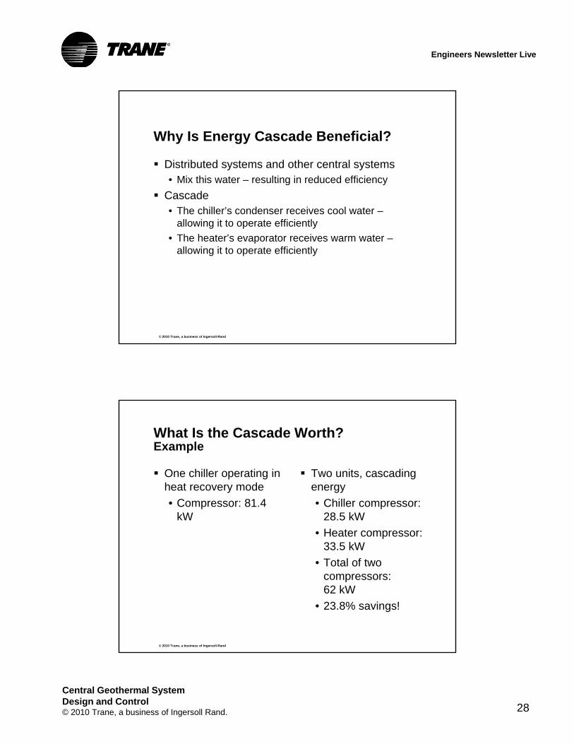
Why Is Energy Cascade Beneficial?
Distributed systems and other central systems • Mix this water – resulting in reduced efficiency
Cascade• The chiller’s condenser receives cool water –
allowing it to operate efficiently
• The heater’s evaporator receives warm water –allowing it to operate efficiently
© 2010 Trane, a business of Ingersoll-Rand
What Is the Cascade Worth?Example
One chiller operating in heat recovery mode
• Compressor: 81.4 kW
Two units, cascading energy
• Chiller compressor: 28.5 kW
• Heater compressor: 33.5 kW
• Total of two compressors:62 kW
• 23.8% savings!

Central Geothermal SystemDesign and Control© 2010 Trane, a business of Ingersoll Rand. 29
Engineers Newsletter Live
Simultaneous Cooling and Heating
Heating Dominant
© 2010 Trane, a business of Ingersoll-Rand
From borefield
Energy Cascadecondenser to evaporator
M
heating dominant mode
Energy Cascade Paths
coolingload
On Cool
PC PLe
M M
Energy Cascade – evaporator to condenser
On Heat
M
PH
B
cond
evap
heatingload
A
cond
evap
To borefield PB
PLc

Central Geothermal SystemDesign and Control© 2010 Trane, a business of Ingersoll Rand. 30
Engineers Newsletter Live
© 2010 Trane, a business of Ingersoll-Rand
Simultaneous Heating/Cooling Controls
© 2010 Trane, a business of Ingersoll-Rand
On Cool
M
M
simultaneous heating & cooling
Heating or Cooling Dominant?
To borefield
From borefield
On Heat
PLe
M
M M
PH
B
cond
evap
heatingload
M
M
M
coolingload
PC
PLc
A
cond
evap
PB
TS10
TS6
TS8

Central Geothermal SystemDesign and Control© 2010 Trane, a business of Ingersoll Rand. 31
Engineers Newsletter Live
© 2010 Trane, a business of Ingersoll-Rand
simultaneous heating & cooling
Cooling Dominant
More BTUs are rejected to the Condenser Energy Transfer loop from the cooling unit(s)…than are extracted from the Evaporator Energy Transfer loop by the heating unit(s)
The system is BTU excess
The Condenser Energy Transfer loop is warmer than the borefield supply water temperature
© 2010 Trane, a business of Ingersoll-Rand
On Cool
M
M
To borefield
From borefield
On Heat
PB
PLe
M
M M
PH
B
cond
evap
heatingload
M
M
M
coolingload
PC
PLc
A
cond
evap
TS6
simultaneous heating & cooling
Cooling Dominant
Central Geothermal SystemDesign and Control© 2010 Trane, a business of Ingersoll Rand. 32
Engineers Newsletter Live
© 2010 Trane, a business of Ingersoll-Rand
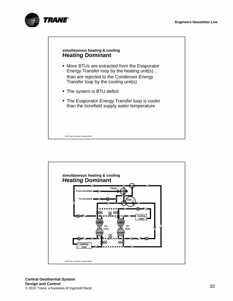
More BTUs are extracted from the Evaporator Energy Transfer loop by the heating unit(s)…than are rejected to the Condenser Energy Transfer loop by the cooling unit(s)
The system is BTU deficit
The Evaporator Energy Transfer loop is cooler than the borefield supply water temperature
simultaneous heating & cooling
Heating Dominant
© 2010 Trane, a business of Ingersoll-Rand
On Cool
M
M
To borefield
From borefield
On Heat
PLe
M
M M
PH
B
cond
evap
heatingload
M
M
M
coolingload
PC
PLc
A
cond
evap
PB
TS10
TS8
simultaneous heating & cooling
Heating Dominant

Central Geothermal SystemDesign and Control© 2010 Trane, a business of Ingersoll Rand. 33
Engineers Newsletter Live
© 2010 Trane, a business of Ingersoll-Rand
On Cool
M
M
To borefield
From borefield
On Heat
PB
PLe
M
M M
PH
B
cond
evap
heatingload
M
M
M
coolingload
PC
PLc
A
cond
evap
TS10
To / From ChillerTo / From
Heater
Cooling Dominant
The system is BTU excess
The Condenser Energy Transfer loop is warmer than the borefield
Transition to Heating Dominant
The system becomes BTU deficit
The Condenser Energy Transfer loop supply temperature drops below the borefield temperature
TS6
simultaneous heating & cooling
Cooling Dominant
© 2010 Trane, a business of Ingersoll-Rand
On Cool
M
M
To borefield
From borefield
On Heat
PLe
M
M M
PH
B
cond
evap
heatingload
M
M
M
coolingload
PC
PLc
A
cond
evap
PB
TS10
TS8
Heating Dominant
The system is BTU deficit
The Evaporator Energy Transfer loop is cooler than the borefield
Transition to Cooling Dominant
The system becomes BTU excess
The Evaporator Energy Transfer loop supply temperature rises above the borefield temperature
To / From ChillerTo / From
Heater
simultaneous heating & cooling
Heating Dominant

Central Geothermal SystemDesign and Control© 2010 Trane, a business of Ingersoll Rand. 34
Engineers Newsletter Live
Key Design Issues
Central Geothermal System Design and Control
© 2010 Trane, a business of Ingersoll-Rand
Key Design Issues
Optimizing life-cycle costs• Borefield sizing Supplemental heating
Auxiliary heat rejection
• Load shedding economizer
Freeze protection

Central Geothermal SystemDesign and Control© 2010 Trane, a business of Ingersoll Rand. 35
Engineers Newsletter Live
© 2010 Trane, a business of Ingersoll-Rand
optimizing life-cycle costs
Borefield Sizing
Peak building demand
Cumulative building demand
Optimization• Reduce peak demand
• Balance annual heating and cooling loads
• Consider a hybrid system design
© 2010 Trane, a business of Ingersoll-Rand
Seasonal Heating-Dominate Load ProfileBuilding Load Profile
0
600000
Jan Feb Mar Apr May Jun Jul Aug Sep Oct Nov Dec Total
Month
En
erg
y
Cooling
Heating

Central Geothermal SystemDesign and Control© 2010 Trane, a business of Ingersoll Rand. 36
Engineers Newsletter Live
© 2010 Trane, a business of Ingersoll-Rand
system options
Supplemental Heating
Boiler downstream of condenser
Use boiler setpoint several degrees lower than chiller setpoint
• Avoids boiler “stealing” the load
© 2010 Trane, a business of Ingersoll-Rand
0
500000
Jan Feb Mar Apr May Jun Jul Aug Sep Oct Nov Dec Total
Seasonal Cooling-Dominate Load ProfileBuilding Load Profile
Month
En
erg
y
Cooling
Heating

Central Geothermal SystemDesign and Control© 2010 Trane, a business of Ingersoll Rand. 37
Engineers Newsletter Live
© 2010 Trane, a business of Ingersoll-Rand
system options
Auxiliary Energy Rejection
Use dry cooler or evaporative fluid cooler• Keeps fluid loop clean
Pump options• Use energy transfer
loop pump Must be sized for
tower pressure drop• Add separate pump –
sidestream Simpler, but
additional pump
© 2010 Trane, a business of Ingersoll-Rand
Building Load Profile Imbalance
A heating-dominate building• Auxiliary heating system (e.g. modular boiler)
• Load shedding economizer
A cooling-dominate building• Auxiliary energy rejection (e.g. fluid cooler)
• Add building heating load like domestic hot water
Optimize the building life-cycle cost• Reducing borefield size
• Increasing borefield utilization for energy efficiency

Central Geothermal SystemDesign and Control© 2010 Trane, a business of Ingersoll Rand. 38
Engineers Newsletter Live
© 2010 Trane, a business of Ingersoll-Rand
Freeze Protection
Two considerations• Low evaporator temperature protection
• Air handler coil freezing
What’s unique about the bidirectional geothermal system?• All systems and loops are interconnected
• A decision to use antifreeze impacts all system elements
© 2010 Trane, a business of Ingersoll-Rand
Freeze Avoidance Strategies
Low evaporator temperature protection• Careful attention to borefield design low temperature
limit• Limit the leaving evaporator temperature• Use supplemental heat (modular boiler) when
evaporator temperature drops to the freezing threshold
Air handler coil freeze protection• Freeze stat with full coil face coverage• Mixed-air blender• Pumped coils

Central Geothermal SystemDesign and Control© 2010 Trane, a business of Ingersoll Rand. 39
Engineers Newsletter Live
© 2010 Trane, a business of Ingersoll-Rand
Pumped Coil
© 2010 Trane, a business of Ingersoll-Rand
Freeze Avoidance Strategies
Pump and piping placement• Place pumps indoors
• Bury all external piping below frost line

Central Geothermal SystemDesign and Control© 2010 Trane, a business of Ingersoll Rand. 40
Engineers Newsletter Live
© 2010 Trane, a business of Ingersoll-Rand
Freeze Avoidance Strategies
Antifreeze• Desirable to avoid if possible
– Cost and efficiency implications throughout the system
– Glycol impact is worse for cooling operation than heating due to viscosity change
– Shell and tube heat exchangers enable a lower evaporator temperature limit than plate and frame heat exchangers
• If required, minimize its concentration
© 2010 Trane, a business of Ingersoll-Rand
Considerations Summary

Central Geothermal SystemDesign and Control© 2010 Trane, a business of Ingersoll Rand. 41
Engineers Newsletter Live
Equipment Performance Requirements
Central Geothermal System Design and Control
© 2010 Trane, a business of Ingersoll-Rand
bidirectional cascade
Desired Equipment Capabilities
Efficiency
Operating Range• Temperatures
• Flow rates
Control• Leaving water temperature stability
• Ability to switch modes

Central Geothermal SystemDesign and Control© 2010 Trane, a business of Ingersoll Rand. 42
Engineers Newsletter Live
© 2010 Trane, a business of Ingersoll-Rand
Unit Efficiency
Can be up to 18% more efficient than ASHRAE 90.1-2007 requirements
Dependent on selection conditions
Make sure unit can unload efficiently while simultaneously making cold chilled water and hot condenser water• Centrifugal compressors may surge
• Positive displacement compressors often a good fit
© 2010 Trane, a business of Ingersoll-Rand
ASHRAE guidance
Temperatures
“For typical buildings, chillers normally provide hot water for space heating at 105°F to 110°F”
source: 2008 ASHRAE Handbook –HVAC Systems and Equipment, p. 8.20

Central Geothermal SystemDesign and Control© 2010 Trane, a business of Ingersoll Rand. 43
Engineers Newsletter Live
© 2010 Trane, a business of Ingersoll-Rand
Example: Positive Affects of Lower Hot Water Temperature
+ 15.1%3.83.3Heating Efficiency (COP)
- 6.5%(that’s good!)
185.3198.2Power (kW)
+ 7.4%24222255Heating Capacity (MBh)
+ 13.3%149.1131.6Cooling Capacity (tons)
Positive Affect
130°F140°FHot Water Temperature
© 2010 Trane, a business of Ingersoll-Rand
operating range
Temperatures
Antifreeze (such as glycol)• Avoid if possible• Minimize amount (10% is better than 25 or 30%)
Temperatures using water• 38°F chilled water• 140°F hot water Using 130°F water
– Increases unit capacity– Increases unit efficiency (15% better)
130°F complements condensing boiler requirements Proper question,
“What hot water temperature do we need?”

Central Geothermal SystemDesign and Control© 2010 Trane, a business of Ingersoll Rand. 44
Engineers Newsletter Live
© 2010 Trane, a business of Ingersoll-Rand
operating range
Flows
Evaporator flow
ASHRAE GreenGuide:
• 1.2 to 2.0 gpm/ton 12 - 20°F ∆T
If Variable Primary Flow
• Ensure adequate turndown Design/Minimum > 2
• 3-pass evaporator may be advantageous
Condenser flow
ASHRAE GreenGuide
• 1.6 to 2.5 gpm/ton 12 - 18°F ∆T
© 2010 Trane, a business of Ingersoll-Rand
Desirable Unit Controls
Operate either in cooling or heating mode
Setpoint stability• Unloading compressors maintain
setpoints• Make 38°F water with no antifreeze
Switch modes without turning compressor off
Ability to respond to variable flow if applied in VPF system• 30% flow rate change per minute

Central Geothermal SystemDesign and Control© 2010 Trane, a business of Ingersoll Rand. 45
Engineers Newsletter Live
TRACE 700™ analysis
Central Geothermal System Design and Control
© 2010 Trane, a business of Ingersoll-Rand
What’s New in TRACE™ 700 v6.2.5
Geothermal loop calculation methodologies
Control algorithms for energy transfer pumps
Default geothermal chiller-heater equipment
Two new output reports• Geothermal Plant Peak Summary
• Geothermal Energy Transfer Summary

Central Geothermal SystemDesign and Control© 2010 Trane, a business of Ingersoll Rand. 46
Engineers Newsletter Live
© 2010 Trane, a business of Ingersoll-Rand
TRACE 700 output
Geothermal Peak Load Summary
© 2010 Trane, a business of Ingersoll-Rand
TRACE 700 output
Geothermal Energy Transfer Summary

Central Geothermal SystemDesign and Control© 2010 Trane, a business of Ingersoll Rand. 47
Engineers Newsletter Live
© 2010 Trane, a business of Ingersoll-Rand
Study Assumptions
Three-story office building• Atlanta, GA
• Philadelphia, PA
• St. Louis, MO
60,000 square feet
Complies withASHRAE 90.1-2007, 62.1-2007
© 2010 Trane, a business of Ingersoll-Rand
Central Geothermal System Comparison
Central Geothermal System (CGS)
• VAV-reheat
• Enthalpy economizer
• Primary-secondary flow
Optimized CGS
• Increased space setpoint (+1°F)
• Low-temperature air VAV (with reset)
• Ventilation reset
• Enthalpy economizer
• Variable primary flow
• Reduced water flow rates

Central Geothermal SystemDesign and Control© 2010 Trane, a business of Ingersoll Rand. 48
Engineers Newsletter Live
© 2010 Trane, a business of Ingersoll-Rand
System Comparisons
90.1-2007 Appendix G Baseline • VAV-reheat, DX cooling, fossil fuel heating
• No economizer required (all locations)
Ground Source Heat Pump (GSHP)• Dedicated OA to heat pump inlet, room neutral
conditions
• 90.1-2007 minimally compliant equipment
Optimized GSHP• Dedicated OA to space, 55º dew point
• Total energy wheel
© 2010 Trane, a business of Ingersoll-Rand
System ComparisonPhiladelphia
50
60
70
80
90
100
over
all
bu
ildin
g e
ner
gy
cost
,%
of
bas
e
9%
Bas
ic G
SH
P
bas
elin
e b
uild
ing
Op
tim
ized
GS
HP
19%
Bas
ic C
GS
9%
Op
tim
ized
CG
S
26%

Central Geothermal SystemDesign and Control© 2010 Trane, a business of Ingersoll Rand. 49
Engineers Newsletter Live
© 2010 Trane, a business of Ingersoll-Rand
System Comparison
All locations
50
60
70
80
90
100
over
all
bu
ildin
g e
ner
gy
cost
,%
of
bas
e
Atlanta Philadelphia St. Louis
Bas
elin
e b
uild
ing
Bas
ic G
SH
P
Op
tim
ized
GS
HP
Bas
ic C
GS
Op
tim
ized
CG
S
Bas
elin
e b
uild
ing
Bas
ic G
SH
P
Op
tim
ized
GS
HP
Bas
ic C
GS
Op
tim
ized
CG
S
Bas
elin
e b
uild
ing
Bas
ic G
SH
P
Op
tim
ized
GS
HP
Bas
ic C
GS
Op
tim
ized
CG
S
© 2010 Trane, a business of Ingersoll-Rand
summary
Central Geothermal Systems
Advantages• Centralize service and maintenance is centralized
• Superior acoustic options
• Airside flexibility
Operation and control• Efficient cascading of simultaneous energy streams
• Efficiently provides both chilled and hot water temperature control
Equipment with wide operating range is available
Analysis results show significant savings

Central Geothermal SystemDesign and Control© 2010 Trane, a business of Ingersoll Rand. 50
Engineers Newsletter Live
© 2010 Trane, a business of Ingersoll-Rand
references for this broadcast
Where to Learn More
www.trane.com/
© 2010 Trane, a business of Ingersoll-Rand
watch past broadcasts
ENL Archives
Insightful topics on HVAC system design:• Chilled-water plants• Air distribution• Refrigerant-to-air systems• Control strategies• Industry standards and
LEED• Energy and the environment• Acoustics• Ventilation• Dehumidification
www.trane.com/ENL