agilent nanospray/nanodapter · agilent nanospray/nanodapter quick start guide installation 3 step...
TRANSCRIPT
Agilent Nanospray/Nanodapter
Quick Start GuideInstallation 3 Step 1. Set up the LC system 3 Step 2. Install the Sensirion Liquid Flow Viewer software 7 Step 3. Set up the LC/MS and install the Nanospray source 10Flow Configuration 13 Direct Flow with Nano Column 14 Nano Flow with Trap Column 15 Nano Flow with Trap Column and Divert Tee 16 Nano Flow with Trap Column and Divert Valve 17Nanodapter Checkout 18 Step 1. Purge the pump and wash station 18 Step 2. Prepare peptide standard 19 Step 3. Start the LC with no column 21 Step 4. Set up the LC/MS 21 Step 5. Install the needle and set up of the system 22 Step 6. Add IRM solution 25 Step 7. Set up the worklist 27 Step 8. Run the method and worklist 27 Step 9. Analyze the data 28Operation Guidelines 30 Operation Guidelines 30 To prevent stability issues 32 To test the Nanodapter at different flow rates 33

1
2 Agilent Nanospray/Nanodapter Quick Start Guide
Troubleshooting 35 If you have flow path blockages 35 If you have unstable flow 36 If you have unstable spray 37 If you have poor chromatography 38 If you have sample carryover 38 If you have poor sensitivity 39Parts 40 PEEK-coated fused-silica capillary 40 G1988-64003 Nanodapter 41 Ultra-Low Dispersion Kit 43
Installation 2
Step 1. Set up the LC system
Agilent Nanospray/Nanodapter Quick Start Guide 3
Installation
Follow these steps to install and configure your Nanospray/Nanodapter System.
If you are installing just the Nanospray Source, go to “Step 3. Set up the LC/MS and install the Nanospray source” on page 10.
Step 1. Set up the LC system
The Nanodapter is supported on the 1290 Infinity II LC system (with G7167B Multisampler) and the 1290 Infinity LC system (with G4226A Autosampler).
The Nanodapter/Nanospray Installation and Maintenance Guide can be found on the Nanospray Customer Information Disc. The topics contained in that guide can also be found in the animated 6000 Series LC/MS Maintenance Guide (revision C or higher).
Table 1 Nanodapter and LC System Setup
Step Refer to
1 Properly install and configure the LC modules. Make sure all LC modules are in good operational condition and are free of contaminants.
LC module Installation Guides.

2 Installation
Step 1. Set up the LC system
4 Agilent Nanospray/Nanodapter Quick Start Guide
2 Install the Ultra-low Dispersion Needle Seat Assembly. Needle Seat Assembly for G7167B Multisampler (left) and G4226A Autosampler shown below.
Nanodapter/Nanospray Installation and Maintenance Guide
3 Install Nanodapter brackets. Brackets for G7167B Multisampler (left) and the G4226A Autosampler shown below.
Nanodapter/Nanospray Installation and Maintenance Guide
Table 1 Nanodapter and LC System Setup
Step Refer to
(p/n 5067-5963)(p/n 5067-5189)

Installation 2
Step 1. Set up the LC system
Agilent Nanospray/Nanodapter Quick Start Guide 5
4 Mount the Nanodapter to the LC system.
• Mount the Valve Drive.
• Install the High-pressure Valve Head.
• Mount the Nanodapter over the Valve Head.
Nanodapter/Nanospray Installation and Maintenance Guide
5 Connect the pump to the Nanodapter with flex tubing.
Nanodapter/Nanospray Installation and Maintenance Guide
Table 1 Nanodapter and LC System Setup
Step Refer to

2 Installation
Step 1. Set up the LC system
6 Agilent Nanospray/Nanodapter Quick Start Guide
6 Connect the Injection Valve (Port 1) to the Flow Sensor of the Nanodapter with a 35-cm PEEK-coated fused-silica tubing.
Nanodapter/Nanospray Installation and Maintenance Guide
Table 1 Nanodapter and LC System Setup
Step Refer to

Installation 2
Step 2. Install the Sensirion Liquid Flow Viewer software
Agilent Nanospray/Nanodapter Quick Start Guide 7
Step 2. Install the Sensirion Liquid Flow Viewer software
The Sensirion Liquid Flow Viewer software is included on the Customer Information Disc.
1 Open the Customer Information Disc.
2 Open the Liquid_Flow_Sensors > SCC1_USB_WindowsDriver folder.
3 Double-click CDM v2.10.00 WHQL Certified.
4 Click Extract in the FTDI CDM Drivers screen.
5 If you are told that the requested operation requires elevation, click OK.
6 If you get a Program Compatibility Assistant message, click Close.
7 If you get the FTDI CDM Drivers screen again, click Extract.
8 If you get the User Account Control message, click Yes.

2 Installation
Step 2. Install the Sensirion Liquid Flow Viewer software
8 Agilent Nanospray/Nanodapter Quick Start Guide
9 When the installation completes, click Finish.
10 From the Customer Information Disc, open the USB-RS485_Sensor_Viewer folder.
11 Double-click Sensirion_USB_RS485_Sensor_Viewer_V2.32.
12 When the installation completes, click Finish.
13 Close all opened program and reboot the computer.
14 Plug the Flow Sensor USB cable into the computer.
Installation 2
Step 2. Install the Sensirion Liquid Flow Viewer software
Agilent Nanospray/Nanodapter Quick Start Guide 9
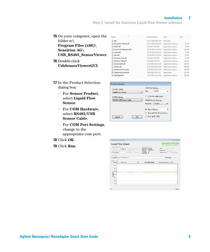
15 On your computer, open the folder c:\Program Files (x86)\Sensirion AG\USB_RS485_SensorViewer.
16 Double-click UsbSensorViewerGUI.
17 In the Product Selection dialog box:
• For Sensor Product, select Liquid Flow Sensor.
• For COM Hardware, select RS485/USB Sensor Cable.
• For COM Port Settings, change to the appropriate com port.
18 Click OK.
19 Click Run.
2 Installation
Step 3. Set up the LC/MS and install the Nanospray source
10 Agilent Nanospray/Nanodapter Quick Start Guide
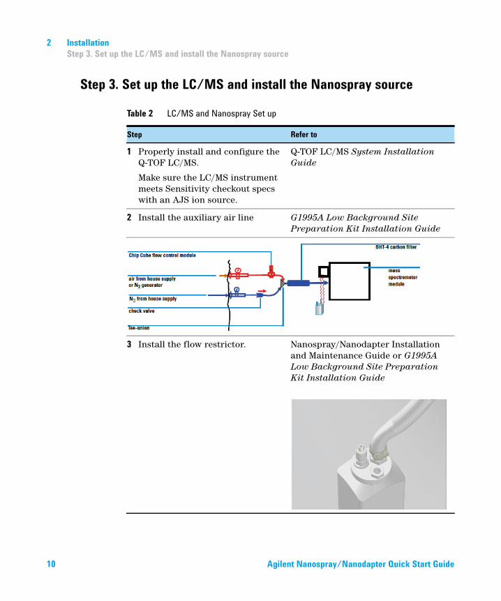
Step 3. Set up the LC/MS and install the Nanospray source
Table 2 LC/MS and Nanospray Set up
Step Refer to
1 Properly install and configure the Q-TOF LC/MS.
Make sure the LC/MS instrument meets Sensitivity checkout specs with an AJS ion source.
Q-TOF LC/MS System Installation Guide
2 Install the auxiliary air line G1995A Low Background Site Preparation Kit Installation Guide
3 Install the flow restrictor. Nanospray/Nanodapter Installation and Maintenance Guide or G1995A Low Background Site Preparation Kit Installation Guide

Installation 2
Step 3. Set up the LC/MS and install the Nanospray source
Agilent Nanospray/Nanodapter Quick Start Guide 11
4 Install the camera and power cord Nanodapter/Nanospray Installation and Maintenance Guide
5 Set the position of the Counter Electrode and LED camera light.
Nanodapter/Nanospray Installation and Maintenance Guide
Table 2 LC/MS and Nanospray Set up
Step Refer to
2 Installation
Step 3. Set up the LC/MS and install the Nanospray source
12 Agilent Nanospray/Nanodapter Quick Start Guide
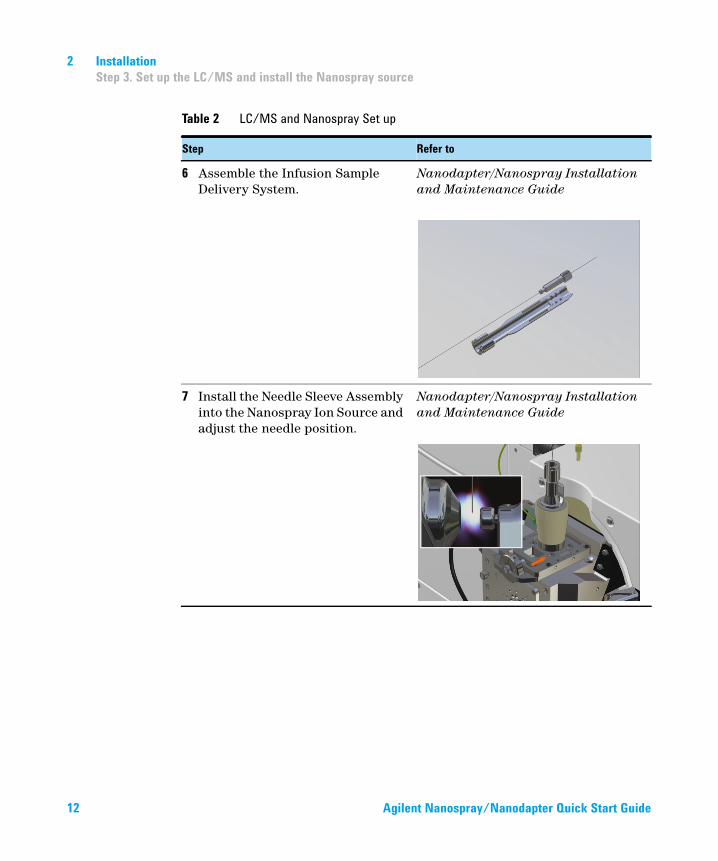
6 Assemble the Infusion Sample Delivery System.
Nanodapter/Nanospray Installation and Maintenance Guide
7 Install the Needle Sleeve Assembly into the Nanospray Ion Source and adjust the needle position.
Nanodapter/Nanospray Installation and Maintenance Guide
Table 2 LC/MS and Nanospray Set up
Step Refer to

Flow Configuration 3
Agilent Nanospray/Nanodapter Quick Start Guide 13
Flow Configuration
Use the PEEK-coated fused-silica tubings and flex tubings to configure the flow of your Nanoflow system.
The Tee Adapters on the Nanodapter can be used to hold Trap Columns or a Tee Diverter in place.
Instructions to connect the correct tubings are shown in the animated Nanospray/Nanodapter Installation and Maintenance Guide, which can be found on the Customer Information Disc.
3 Flow Configuration
Direct Flow with Nano Column
14 Agilent Nanospray/Nanodapter Quick Start Guide
Direct Flow with Nano Column
Use this configuration to check out the Nanodapter setup.
In this configuration, the sample flows directly from the Injection Valve to the Nano Column.
Infinity II Pump
MultiSampler
Electronic Flow
Sensor
Nano Flow Direct
G1992A
NanoSpray Ion
Source
Resistor Capillary to
waste
Multisampler
Column Oven
2.1 mm x 10 cm
6-port valve
Nano Column
75 µm typical
15 to 50 cm1
6
2
6
12
3
3
4 5
4 5
50 cm
70 cm 15 cm
Caution – Do not sharply bend Fused Silica Capillary Tubing to avoid breaking or cracking

Flow Configuration 3
Nano Flow with Trap Column
Agilent Nanospray/Nanodapter Quick Start Guide 15
Nano Flow with Trap Column
In this flow configuration, the sample flows through a Trap Column before it goes into the Nano Column.
The length of the transfer PEEK-coated fused-silica capillary depends on the length of the Nano Column.
Recommended transfer capillary and column lengths are listed in Table 3.
Table 3 Recommended capillary and column length combinations with Trap Column
Transfer PEEK-coated fused-silica
tubing length
Nano Column length
35 cm 15 cm
20 cm 25 cm
10 cm 50 cm
Infinity II Pump
MultiSampler
Nano Flow with Trap Column
G1992A
NanoSpray Ion
Source
Multisampler
Column Oven
2.1 mm x 10 cm
6-port valve
Nano Column
75 µm typical
15 to 50 cm1
6
2
6
12
3
3
4 5
4 5 Trap Column
35 cm
35 cm20 cm10 cm
50 cm
5 cm
15 cm25 cm50 cm
Electronic Flow
Sensor
Resistor Capillary to
waste

3 Flow Configuration
Nano Flow with Trap Column and Divert Tee
16 Agilent Nanospray/Nanodapter Quick Start Guide
Nano Flow with Trap Column and Divert Tee
In this flow configuration, the sample flows through a Trap Column and then splits between waste (via the Divert Valve) and the Nano Column.
The length of the transfer PEEK-coated fused-silica capillary depends on the length of the Nano Column.
Recommended transfer capillary and Column lengths are listed in Table 4
Table 4 Recommended capillary and column length combinations with Trap Column
Transfer PEEK-coated fused-silica
tubing length
Nano Column length
35 cm 15 cm
20 cm 25 cm
10 cm 50 cm
Infinity II Pump
MultiSampler
Nano Flow with Trap Column and Divert Tee
G1992A NanoSpray Ion
Source
Multisampler
Column Oven2.1 mm x 10 cm
6-port valve
Nano Column75 μm typical15 to 50 cm1
62
612
3
34 5
4 5 Trap ColumnDivert Tee
Waste
35 cm20 cm10 cm
10 cm5 cm
50 cm
35 cm
15 cm25 cm50 cm
Electronic Flow Sensor
Resistor Capillary to waste

Flow Configuration 3
Nano Flow with Trap Column and Divert Valve
Agilent Nanospray/Nanodapter Quick Start Guide 17
Nano Flow with Trap Column and Divert Valve
In this flow configuration, the sample flows through a Trap Column and then splits between waste (via the Divert Valve) and the Nano Column.
The length of the transfer PEEK-coated fused-silica capillary depends on the length of the Nano Column.
Recommended transfer capillary and Column lengths are listed in Table 4
Table 5 Recommended capillary and column length combinations with Trap Column
Transfer PEEK-coated fused-silica
tubing length
Nano Column length
50 cm 15 cm
35 cm 25 cm
10 cm 50 cm
Infinity II Pump
MultiSampler
Nano Flow with Trap Column and Divert Valve
G1992A NanoSpray Ion
Source
Multisampler
Column Oven2.1 mm x 10 cm
6-port valve
Nano Column75 μm typical15 to 50 cm1
62
612
3
34 5
4 5 Trap Column
50 cm35 cm10 cm
50 cm
5 cm35 cm
15 cm25 cm50 cm
Electronic Flow Sensor
Resistor Capillary to waste
Waste

4 Nanodapter Checkout
Step 1. Purge the pump and wash station
18 Agilent Nanospray/Nanodapter Quick Start Guide
Nanodapter Checkout
Step 1. Purge the pump and wash station
Before you begin, make sure you have:
• LCMS-grade acetonitrile
• LCMS-grade water
• 0.1% formic acid
• isopropyl alcohol
1 Prepare and install:
• Channel A: LCMS-grade water with 0.1% formic acid
• Channel B: 90:10 LCMS-grade acetonitrile:LCMS-grade water with 0.1% formic acid
• Wash solvent S1: 2.7% LCMS-grade acetonitrile:LCMS-grade water with 0.1% formic acid
• Seal wash solvent: 50:50 isopropyl alcohol:LCMS-grade water
2 Purge the pump and the wash solvent station.

Nanodapter Checkout 4
Step 2. Prepare peptide standard
Agilent Nanospray/Nanodapter Quick Start Guide 19
Step 2. Prepare peptide standard
This step creates a 20 fmol/μL working solution that contains 20 fmol/μL HSA peptide standard mix in 0.1% formic acid, 15% LCMS-grade acetonitrile:LCMS-grade water.
Before you begin, make sure you have:
• LCMS-grade acetonitrile
• LCMS-grade water
• high-quality polypropylene centrifuge tube
• HSA peptide standard mix (p/n G2455-85001)
• 0.1% formic acid
• micropipette
• sample vial (p/n 9301-0977)
• vial cap (p/n 5182-3458)
1 Make a Dilution Solvent from the compounds in Table 6 in a high-quality polypropylene centrifuge tube.
Do not use polyethylene labware because of the presence of extractable compounds. Do not use glassware to avoid formation of sodium adducts of the peptides.
2 Allow the vial of HSA peptide standard mix to come to room temperature.
Table 6 Dilution Solvent
Reagent Percentage (volume)
LCMS-grade acetonitrile 15%
LCMS-grade water with 0.1% formic acid 85%

4 Nanodapter Checkout
Step 2. Prepare peptide standard
20 Agilent Nanospray/Nanodapter Quick Start Guide
3 Make a 1 pmol/μL Stock Solution. Use a micropipette to measure the amounts listed in Table 7.
a Add 500 μL Dilution Solvent to the vial of HSA peptide standard mix to create the Stock Solution.
b Close the vial cap and mix the vial briefly on a vortex mixer.
c Allow the Stock Solution to stand for four to five minutes at room temperature to ensure dissolution of the HSA peptide standard mix.
d Mix briefly again on a vortex mixer to homogenize the Stock Solution.
Do not overmix on the vortex mixer or the sample can become foamy.
4 Make a 20 fmol/μL concentration Working Solution.
Do not use glass vials. Hydrophobic peptides will be lost on glass surfaces.
a Add 196 μL Dilution Solvent to a sample vial.
b Add 4 μL Stock Solution to the Dilution Solvent in the sample vial
c Close the sample vial with a vial cap and briefly mix on a vortex mixer.
Make sure no bubbles form in the Working Solution. Bubbles injected into the LC can cause variability in responses.
d Immediately refrigerate the samples at 4°C, either in the refrigerator or in the Multisampler.
The samples must be analyzed within one day.
Table 7 Stock Solution
Reagent Amount (volume)
Dilution Solvent 500 µL
HSA peptide standard mix vial
Table 8 Working Solution
Reagent Amount (volume)
Dilution Solvent 196 µL
Stock Solution 4 µL

Nanodapter Checkout 4
Step 3. Start the LC with no column
Agilent Nanospray/Nanodapter Quick Start Guide 21
Step 3. Start the LC with no column
1 Open the Sensirion Liquid Flow Viewer. Run the program to display the split flow rate.
2 Set the pump flow to 0.06 mL/min and turn on the pump.
With no column installed, the split flow stabilizes at 5000 nL/minute or greater.
3 Turn off the pump and allow the pump pressure to fall to less than 10 bar.
Step 4. Set up the LC/MS
1 Set the capillary voltage to 900 V. Leave the LC/MS in Standby mode.
2 Turn on the video capture program to view the needle position inside the Nanospray source.
3 Set the vertical setting on the Nanospay source to 12.0 mm height.
This position puts the needle tip above the opening in the spray cap.
4 Set the horizontal setting on the Nanospray source to 3.0 mm away from the front face of the spray cap.
This position puts the needle about halfway between the electrodes, but slightly closer to the spray cap on the left side of the picture.

4 Nanodapter Checkout
Step 5. Install the needle and set up of the system
22 Agilent Nanospray/Nanodapter Quick Start Guide
Step 5. Install the needle and set up of the system
1 Insert the Needle Assembly (with needle and Nano column installed) into the Nanospray source.
Refer to the animated Nanospray/Nanodapter Installation and Maintenance Guide for instructions to assemble the Needle Assembly.
2 Turn on the pump. Set the flow rate to 0.083 mL/minute.
The split flow settles at around 300 nL/min. A drop of mobile phase forms in approximately one minute on the end of the needle. If neither of these events happen, locate and fix the leak before you proceed.
3 Adjust the pump flow rate up or down to achieve a split flow rate close to 300 nL/min.
A suggested deviation is within 5%, +/- 15 nL/minute of the target value. Start at 0.050 mL/minute with a maximum flow rate of 0.150 mL/minute. Do not exceed 750 Bar back pressure set in the method.
4 Insert the column and holder into the Nanospray source.
CAUTIONUse care when you type the pump flow rate. A value of “0.83” mL/minute instead of “0.083”mL/minte puts the system at very high pressure and flow. Flow rates greater than 400 nL/min can damage the needle by splitting the tip. This type of damage is difficult to see or detect. It can result in an erratic spray and the need for very high capillary voltages.
CAUTIONTo avoid over pressure and permanent damage to the Sensirion Flow Sensor, always set the LC pump pressure limit and flow response rate to:• Pressure Limit: 750 Bar• Flow Ramp up: 25 mL/minute• Flow Ramp down: 25 mL/minute
CAUTIONDo not touch the column or capillary to any surface as column or capillary can become fractured. Do not touch the needle tip to any surface as the needle tip can be damaged.

Nanodapter Checkout 4
Step 5. Install the needle and set up of the system
Agilent Nanospray/Nanodapter Quick Start Guide 23
The actual settings of the dials on the Nanospray source depends on the instrument and on how the back opening of the needle is trimmed during its installation. A typical view of the needle position is shown in Figure 1.
The ideal needle position is a balance between robustness and sensitivity. You can achieve higher signal when the needle is close to the spray cap (left side) or in a low position (into the drying gas stream). But these positions shorten the life of the needle.
Figure 1 Typical needle position
5 Turn on the LC/MS.
A signal might not be visible if a drop is on the end of the needle.
6 Increase the capillary voltage in 50 V steps until you see a signal.
Typically, you need not apply more than 1300 V capillary voltage to see a signal.

4 Nanodapter Checkout
Step 5. Install the needle and set up of the system
24 Agilent Nanospray/Nanodapter Quick Start Guide
7 Allow the signal to stabilize.
In general, higher capillary voltage gives greater signal but shortens the life of the needle. Capillary voltages over 1500 V are uncommon and difficult to control.
If the spray does not start:
a Turn off the pump and allow the drop to evaporate.
b As soon as the drop disappears, turn the pump on again.
8 Allow the system a few minutes to stabilize. Fine-tune the signal as needed:
• Adjust the Vernier positions by +/- 0.5 mm increments.
• Vary the capillary voltage also.
• After the needle is completely dried and the spray is established, a spray can be sustained with a lower capillary voltage. A lower capillary voltage can improve the life of the needle.

Nanodapter Checkout 4
Step 6. Add IRM solution
Agilent Nanospray/Nanodapter Quick Start Guide 25
Step 6. Add IRM solution
1 Prepare the IRM Working Solution.
Refer to the animated Nanospray/Nanodapter Installation and Maintenance Guide for instructions.
2 Apply the IRM solution to the Nanospray source.
Refer to the animated Nanospray/Nanodapter Installation and Maintenance Guide for instructions.
Apply carefully. IRM compounds are difficult to remove if too much is applied.
3 You can adjust the IRM abundances to a certain degree by adjusting the drying gas temperatures, which affects the responses.

4 Nanodapter Checkout
Step 6. Add IRM solution
26 Agilent Nanospray/Nanodapter Quick Start Guide
Figure 2 Example of a system with low background. m/z 1221.9906 is the IRM signal.
NOTEHigh background in the system significantly diminishes the response of peptides. Identify and remove any source of high background to acquire data of high sensitivity and high quality. Sources of background include: • the exhaust system in the lab to which the LC/MS is vented• the lab air, the drain bottle and hose, the MS source, mobile phases used in the LC, and
contamination from previous samples injected into the system• An example of a system with low background is shown below (the 1221.9906 m/z
response is the IRM signal).

Nanodapter Checkout 4
Step 7. Set up the worklist
Agilent Nanospray/Nanodapter Quick Start Guide 27
Step 7. Set up the worklist
Set up a worklist to follow good laboratory practice:
• Run at least 2 or 3 blanks before running the samples to condition the column and stabilize the spray and mass spectrometer.
• Run blank after each batch of samples (for example, control samples) to reduce carry overs and increases the accuracy of the results.
Running a blank after each batch of samples also increases the life span of the column.
Step 8. Run the method and worklist
1 Start the worklist.
The method loads the sample at 300 nL/minute from the sample loop onto the column. This takes 8 minutes after the Multisampler switches to mainpass mode. No data is acquired during this time.
After the loading is complete, the Multisampler changes to bypass mode, the pump gradient starts, and the LC/MS acquisition starts.
The method parameter files AcquisitionMethod_ReportNanodapter6550.xls and AcquisitionMethod_ReportNanodapter6530.xls are provided on the Customer Information Disc.

4 Nanodapter Checkout
Step 9. Analyze the data
28 Agilent Nanospray/Nanodapter Quick Start Guide
Step 9. Analyze the data
1 Open the MassHunter Qualitative Analysis program.
2 After the run completes, load the data file into MassHunter Qualitative Analysis.
3 Extract the EIC of the following peptide m/z values. Use a +/- 20 ppm window.
4 Integrate the data. Use the Agile2 integrator.
Figure 3 shows typical results.
The abundance value you get can differ from this example due to the needle position, capillary voltage, tune parameters, preparation of the HSA synthetic peptides standard, and other factors.
Look for these results:
• Seven peaks due to the seven peptides are present.
• The FWHM (Full Width Half Maximum) value for the most intense peptide LVNEVTEFAK, 575.3111 m/z needs to be less than 0.25 minutes.
• The standard deviation of the retention time of this peptide needs to be less than 1%.
Note that FWHM and standard deviation values are guidelines for installation only.
Table 9 HSA Ions and Charge States
HSA Ions Charge State
686.287019 +2
464.250360 +2
575.311146 +2
547.317433 +3
637.648743 +3
671.821021 +2
581.636215 +3

Nanodapter Checkout 4
Step 9. Analyze the data
Agilent Nanospray/Nanodapter Quick Start Guide 29
Note that:
• The last peptide, HPYFYAPELLFFAK 581.6362 m/z, is hydrophobic. Its abundance depends on the age of the sample.
• Sensitivity is instrument-dependent, so no sensitivity metrics are provided.
Figure 3 EIC of the extracted ion for HSA

5 Operation Guidelines
Operation Guidelines
30 Agilent Nanospray/Nanodapter Quick Start Guide
Operation Guidelines
Instructions to connect the correct tubings are shown in the animated Nanospray/Nanodapter Installation and Maintenance Guide, which can be found on the Customer Information Disc.
Operation Guidelines
• When attaching or replacing the spray needle, do not over-tighten the black Needle Nut. Always hand-tighten.
To properly replace a needle:
a Insert a new spray needle (blunt end first) through a new black conductive ferrule until the needle extends approximately 1 to 2 mm. Make sure the spray needle can easily slide through the black conductive ferrule.
b Carefully use your fingernail or a flat object to push the spray needle until the end of the needle is flush with the conductive ferrule.
c Hand-tighten the Needle Nut until the needle is snug but not tight. Turn the Needle Nut an additional 120 degrees to seal the junction.
d Wait for small droplets to form on the end of the needle tip. For better visibility, shine a light onto the tip. The small droplet will glow when present.
e Insert the spray needle, Needle Nut, and column into the Needle Assembly.
CAUTIONIf you overtightened the black Needle Nut, you can break the needle. Damage to the needle inside the ferrule is difficult to diagnose.

Operation Guidelines 5
Operation Guidelines
Agilent Nanospray/Nanodapter Quick Start Guide 31
• Spray needles, when first installed, require a low starting voltage. For a flow rate of 300 nL/min and a good source electrical ground, the voltage setting for optimum spray is usually between 1250 and 1300 V.
a Start with the Vcap at 1200 V and insert the Needle Assembly into the source housing.
b Watch the camera image while you slowly lower the needle midway into the electrode elements.
c If the droplet is observed, set the Vcap to 1300 volts. The electrospray should now start.
d If the droplet is observed, but the spray does not start, stop the flow and wait for the droplet to evaporate or gently shake the needle to remove the droplet to induce the start of spray. If the tip is damaged, replace the needle.
e If no droplet is observed, and no ions are detected on the MS system, the tip is blocked. Replace the tip.
• Never run 8 μm to 10 μm Nanospray tips at a flow rate over 500 nL/min. The tip can crack and yield erratic spray and unusable data. If the liquid wicks up the side of the tip, remove the column and tip from the instrument and inspect for damage.
• Make sure to attach the grounding wire from the Nanospray source to the instrument chassis. Resistance greater than 10 ohm can result in spray instability.

5 Operation Guidelines
To prevent stability issues
32 Agilent Nanospray/Nanodapter Quick Start Guide
To prevent stability issues
• To avoid spray needle blockage from sample particles:
• Clean the sample with a Solid Phase Extraction (SPE) column or cartridge before injection. Detergents and tissue debris from samples must be removed to prevent clogs in the needle or tubings.
• Use a trapping column before the analytical column to trap all particulates and insoluble materials.
• Completely digest protein before running the sample. Undigested protein can plug the spray needle or column.
• For protein digest samples, keep the acetonitrile concentration under 60%. Do not raise the acetonitrile to 90% at the end of the run.
In some LC methods, the analytical column is flushed by holding the gradient at 90% acetonitrile for 10 minutes or more to elute the hydrophobic peptides or large precipitants from the column. These peptides can cause high back pressure or blockage, which requires a change of the trapping or analytical column.
• Shavings or particles from the conductive black Nanospray needle ferrule can cause blockage in the spray needle tip. To verify presence of particles in the spray needle, look for black particles at the needle tip under a microscope. If shavings are present, replace the black ferrule and spray needle.
• If white particles are observed under a microscope in the spray needle tip, replace the column.
CAUTIONColumns can degrade when running at high flow velocities (> 6 cm/seconds at high pressures).

Operation Guidelines 5
To test the Nanodapter at different flow rates
Agilent Nanospray/Nanodapter Quick Start Guide 33
To test the Nanodapter at different flow rates
1 Connect the orange PEEK-coated fused-silica capillary to the output of the Flow Sensor. Put the other end of the capillary into a small waste container.
2 Purge the UHPLC Pump with 50:50 acetonitrile:water for 5 minutes.
3 Set the pump Pressure limit to 750 bar.
4 Set the LC pump flow rate to 0.050 mL/minutes.
5 Change the acetonitrle:water solution to 3:97.
6 Open the Sensirion Flow Viewer and make sure it is visible on your computer display.
7 Make sure that the pressure listed in the LC Icon panel shows over 180 bar.
8 In the Sensirion Flow viewer, make sure the Nano flow is over 500 nL/minute.
9 When the Sensirion Flow viewer shows a steady plot across the screen, take a note of the LC pump pressure and the Nano flow rate.
10 Change the LC pump flow setting from 0.050 mL/minute to 0.100 mL/minute.
11 In the Sensirion Flow viewer, make sure that the Nano flow rate has changed from approximately 500 nL/minute to approximately 1000 nL/minute (or approximately doubled).
12 Increase the flow rate from 0.100 mL/minute to 0.150 mL/minute.
13 Check that the pressure has increased proportionately. The pressure can be as high as 700 bar or more.
14 Check that the Nano flow has increased by about the same ratio.
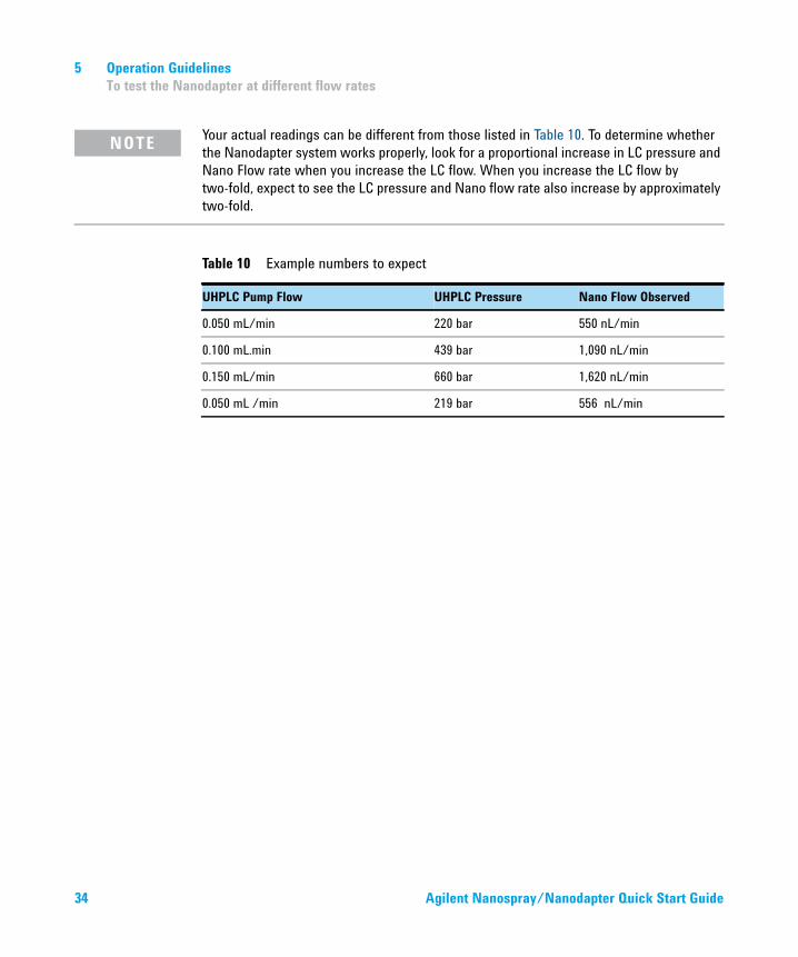
Table 10 shows example results of this test. Make sure you wait five minutes between readings.
CAUTIONTo avoid over pressure and permanent damage to the Sensirion Flow Sensor, always set the LC pump pressure limit and flow response rate to:• Pressure Limit: 750 Bar• Flow Ramp up: 25 mL/minute• Flow Ramp down: 25 mL/minute
5 Operation Guidelines
To test the Nanodapter at different flow rates
34 Agilent Nanospray/Nanodapter Quick Start Guide
NOTEYour actual readings can be different from those listed in Table 10. To determine whether the Nanodapter system works properly, look for a proportional increase in LC pressure and Nano Flow rate when you increase the LC flow. When you increase the LC flow by two-fold, expect to see the LC pressure and Nano flow rate also increase by approximately two-fold.
Table 10 Example numbers to expect
UHPLC Pump Flow UHPLC Pressure Nano Flow Observed
0.050 mL/min 220 bar 550 nL/min
0.100 mL.min 439 bar 1,090 nL/min
0.150 mL/min 660 bar 1,620 nL/min
0.050 mL /min 219 bar 556 nL/min

Troubleshooting 5
If you have flow path blockages
Agilent Nanospray/Nanodapter Quick Start Guide 35
Troubleshooting
If you have flow path blockages
N
Cause Solution
1 Fused silica particles in
system
• Solvent-rinse capillaries and fittings with isopropanol or
acetontrile prior to installation.
• Avoid overtightening fittings.
• Avoid excessive bending or coiling of the capillaries. If you
coil to a radius of less than 40 mm, you will damage the
capillaries.
• Avoid kinking, bending or crushing capillaries with LC doors
or cover panels.
• Backflush capillaries if they are already blocked.
2 Particles from solvent or
sample
• Always use LCMS-grade reagents.
• Clean up samples per Sample Preparation Guide.
3 Nanospray needle blocked
due to heat without flow
• If you do not plan to use the system for several days, remove
the nanospray needle/column holder assembly and store in
protective plastic sleeve.
• If the needle is blocked, flush with 100% B1 for 30 min. This
sometimes removes the blockage.
4 Nanospray needle or tubing
blocked by detergent or
sample tissue debris.
• Clean the sample before injection. Use the process
appropriate to the nature of the sample and sample extraction
method, such as SPE cartridges, filters or centrifugation.
5 Troubleshooting
If you have unstable flow
36 Agilent Nanospray/Nanodapter Quick Start Guide
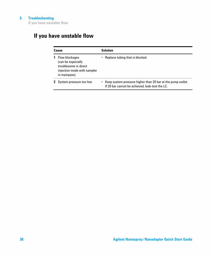
If you have unstable flow
Cause Solution
1 Flow blockages
(can be especially
troublesome in direct
injection mode with sampler
in mainpass)
• Replace tubing that is blocked.
2 System pressure too low • Keep system pressure higher than 20 bar at the pump outlet.
If 20 bar cannot be achieved, leak-test the LC.

Troubleshooting 5
If you have unstable spray
Agilent Nanospray/Nanodapter Quick Start Guide 37
If you have unstable spray
Cause Solution
1 Capillary voltage not set
correctly
• Adjust the capillary voltage.
• Using the 8 µm needle tips and liquid flow between 175
and 300 nL/minute, make sure the capillary voltage is
between 1600 and 2000 volts.
• New needles usually require less voltage, but need slightly
more as the needle ages and the tip becomes eroded or
enlarged.
2 Nanospray needle not
positioned correctly
• See the animated Nanospray/Nanodapter Installation and Maintenance Guide.
3 Flow path blockages • Replace the tubing that is blocked.
4 Nanospray needle tip is
damaged or partly blocked.
(You observe sputtering or
split spray)
• Replace the needle, reinstall the needle/column holder
assembly in the source, and adjust needle position.
5 Ferrule not making good seal
with needle
• Replace the ferrule, reinstall the needle/column holder
assembly in the source, and adjust needle position.
6 Flow too great or needle tip
enlarged
(You observe steady bowed
stream of liquid.)
• Reduce the LC flow.
• Replace the needle as above.

5 Troubleshooting
If you have poor chromatography
38 Agilent Nanospray/Nanodapter Quick Start Guide
If you have poor chromatography
If you have sample carryover
Cause Solution
1 Gaps at LC connections • When you connect a capillary to a fitting or the column, push
the capillary into the fitting firmly and smoothly to avoid gaps.
• When connections are leaking, set column flow to zero,
loosen the fitting, reinsert the fused silica and retighten the
fitting. If you tighten the fitting without re-seating the fused
silica tube, you may allow a gap to remain between the fused
silica and the fitting. This will result in peak dispersion.
2 Note: Chromatography in
enrichment column mode is
generally not as good as in
direct injection mode.
• Switch to direct injection mode if that is an option. Consider:
• Your injection volume
• Level of salts and other water-soluble contaminants.
Cause Solution
1 No needle wash • Set up needle wash for well-plate sampler.
2 Inappropriate needle wash
solvent
• Switch to a solvent combination in which your sample is
completely soluble.
3 In enrichment column mode,
residual hydrophobic
peptides in the injection
system
• Inject several rounds of blanks with high organic until the
peaks are gone.

Troubleshooting 5
If you have poor sensitivity
Agilent Nanospray/Nanodapter Quick Start Guide 39
If you have poor sensitivity
Cause Solution
1 Detector gain adjustment
needs to be redone
• See instructions for verifying detector setting in your
LC/MSD Trap documentation.
2 Capillary voltage too high,
causing corona which can
destroy peptides
• Reduce the capillary voltage.
3 Sample degradation from
sitting at room temperature
• Prepare fresh samples.
• If you have the optional thermostat on the micro well-plate
sampler, make sure it is turned on and set to 4°C.
4 Peptides adsorbed on vial
surface
• Switch to a different vial material (glass or plastic).
5 Bad injection due to air
bubble at bottom of vial
• Tap vial gently to dislodge air bubble.
6 Unstable spray • See “If you have unstable spray” on page 37 of this chapter.

6 Parts
PEEK-coated fused-silica capillary
40 Agilent Nanospray/Nanodapter Quick Start Guide
Parts
The Parts List for the Nanospray source are in the Nanospray/Nanodapter Installation and Maintenance Guide (animated) and the LC/MS Maintenance Guide (animated, revision C or later).
This section contains parts for the Nanodapter.
PEEK-coated fused-silica capillary
Each capillary comes with:
• 5043-0915 Mounting Tool
• 5-mm Seal-tight Screw ×2 (×1 in G1988-68063 and G1988-68068)
• 8-mm ID Front Ferrule ×2 (×1 in G1988-68063 and G1988-68068)
Table 11 PEEK-coated fused-silica capillary
Kit Part Number Description
G1988-68063 3.8-m, beige
G1988-68068 3.2-m, orange
G1988-68069 50-cm, blue
G1988-68070 35-cm, blue
G1988-68071 70-cm, blue
G1988-68072 20-cm, blue
G1988-68073 10-cm, blue

Parts 6
G1988-64003 Nanodapter
Agilent Nanospray/Nanodapter Quick Start Guide 41
G1988-64003 Nanodapter
¬
➊
➋
➌➍ ➍ ➏
➐
➐
➑
➒➌➓
➋
➀➎
➁

6 Parts
G1988-64003 Nanodapter
42 Agilent Nanospray/Nanodapter Quick Start Guide
Table 12 Nanodapter Parts List
Number Part
➊ G1988-00003 Valve Mount Base
➋ G1988-68068 3.2-m orange PEEK-coated fused-silica capillary
➌ 8121-2817 2-m SCC1-USB Sensor cable
➍ G1988-20051 Knob
➎ G1988-20060 Tee Adapter
➏ G1988-80016 Divert Tee
➐ 5021-1823 400-mm Flex Tubing with 0100-2259 Nut and 0100-2258 Ferrule
➑ G1988-00006 Capillary Basket
➒ G1988-68063 3.8-m beige PEEK-coated fused-silica capillary
➓ G1988-60020 UHPLC Tee Clamp Assembly
➀ 0960-3228 Flow Pressure Sensor (underneath Capillary Basket)
➁ 5065-9925 15-cm 2.7 µm Nano Column
➂ G1988-60006 Needle Sleeve Assembly
➃ G1988-60028 Nanospray Source Tray Assembly
➄ G1988-00007 Tray Cover
➃
➄

Parts 6
Ultra-Low Dispersion Kit
Agilent Nanospray/Nanodapter Quick Start Guide 43
Ultra-Low Dispersion Kit
The Ultra Low Dispersion Kit is available for the G7167B Multisampler (left) and G4226A Autosampler.
U
Table 13 Ultra Low Dispersion Kits
Module Kit Part Number Seat Assembly Part Number
G7167B Multisampler 5067-5963 G4267-87020
G4226A Autosampler 5067-5189 G4226-87030

Agilent Technologies, Inc. 2017
Revision A, January 2017
*G1988-90001*G1988-90001Revision A0
www.agilent.com
In This Book
This guide contains information to get started with the Nanospray ion source and the Nanodapter accessory.
Detailed installation and maintenance instructions are found in the animated Nanospray/Nanodapter Installation and Maintenance Guide on the Customer Information Disc.