agreement no.ce 21/2012 (ws) desalination plant at tseung
TRANSCRIPT
ReportAuthorizedForIssueBy: ForandonBehalfof
Black&VeatchHongKongLimited
Black&VeatchHongKongLimited25/F,MillenniumCity6392KwunTongRoadKowloonHongKong
WaterSuppliesDepartment6/F,ShaTinGovernmentOfficesNo.1SheungWoCheRoadNewTerritoriesHongKongDecember2014
AgreementNo. CE21/2012(WS)DesalinationPlantatTseungKwanO‐FeasibilityStudyConstructionandDemolitionMaterialManagementPlan8901/B&V/0021Issue3

AgreementNo.CE21/2012(WS)DesalinationPlantatTseungKwanO 8901/B&V/0021Issue3FeasibilityStudy C&DMaterialManagementPlan
January2015 B&V
DOCUMENTCONTROL AgreementNo. CE21/2012(WS)DesalinationPlantatTseungKwanO–FeasibilityStudy
No:8901‐0021
AMENDMENTRECORD PreparedBy:B&V
ConstructionandDemolitionMaterialManagementPlan
Client:WaterSuppliesDepartmentInitial:WCWDate:January2015
Pages DateIssueNo. Description Initials
All Nov2013 1 ForWSDcomment TT
All Oct2014 2 IncorporatedWSDcomment WCW
All Jan2015 3 IncorporatedWSDcomment WCW
*TheRegisteredRecipientisresponsiblefordestroyingormarkingas‘superseded’allsupersededdocuments.

AgreementNo.CE21/2012(WS)DesalinationPlantatTseungKwanO 8901/B&V/0021Issue3FeasibilityStudy C&DMaterialManagementPlan
January2015 i B&V
TableofContentsPage
1 ProjectOverview.........................................................................................................................................1 1.1 Background....................................................................................................................................................................1 1.2 ProjectDescription.....................................................................................................................................................1 1.3 PurposeandScopeofC&DMaterialManagementPlan..............................................................................2 1.4 ImplementationProgramme...................................................................................................................................2
2 DevelopmentConstraints........................................................................................................................3 2.1 General.............................................................................................................................................................................3 2.2 TrafficImpacts..............................................................................................................................................................4 2.3 MarineTrafficImpacts..............................................................................................................................................4 2.4 EnvironmentalConsiderations..............................................................................................................................4 2.5 UtilitiesandServices..................................................................................................................................................6 2.6 ProjectInterfaces.........................................................................................................................................................6
3 DevelopmentOptions................................................................................................................................8 3.1 ConstructionofDesalinationPlant.......................................................................................................................8 3.2 ConstructionofIntakeandOutfallSystems.....................................................................................................8 3.3 Constructionof1200mmDiameterTrunkFeedSystem.............................................................................8
4 ManagementofC&DMaterials...............................................................................................................9 4.1 QuantityofC&DMaterials........................................................................................................................................9 4.2 Generation,ReuseandRecycleofC&DMaterials.......................................................................................14
5 FindingsandRecommendations........................................................................................................16 5.1 SummaryofFindings..............................................................................................................................................16 5.2 SummaryofRecommendations..........................................................................................................................16 APPENDICES
AppendixA–ProposedSiteLayout
AppendixB–ProposedConstructionProgramme
AppendixC–EstimatedVolumeofC&DMaterials
ListofTables
Table1‐1ImplementationProgrammeoftheContract.................................................................................................3 Table4‐1EstimatedQuantitiesofDifferentC&DMaterialsGenerated...............................................................11 Table4‐2MethodandProgrammeofDisposalofC&DMaterialsandImportFillMaterial........................12
Name Signature Date
Preparedby KevinWong
Checkedby LouisChan
Reviewedby ChristinaKHartinger
AgreementNo.CE21/2012(WS)DesalinationPlantatTseungKwanO 8901/B&V/0021Issue3FeasibilityStudy C&DMaterialManagementPlan
January2015 1 B&V
1 PROJECT OVERVIEW
1.1 Background
1.1.1 WSD has promulgated the Total Water Management (TWM) strategy in Year 2008 withemphasis on “save first and then increase”. For the water supply, alternative resource ofwatersupplyisnecessarytobeidentifiedtocaterforunpredictableclimatechangesuchasdramaticchangeinrainfall.
1.1.2 WaterSuppliesDepartment (WSD)conducteda feasibility studyandapilotplant studyonthedevelopmentofdesalinationfacilities inHongKongin2002and2007respectively.ThestudiesconfirmedthetechnicalfeasibilityofdesalinationusingreverseosmosisunderlocalconditionstoproducepotablewatercomplyingwiththeWorldHealthOrganization(WHO)standards.
1.1.3 TheproposeddesalinationplantinTseungKwanO(TKO),withawaterproductioncapacityof 135million litres per day (MLD) expandable to 270MLD is a pioneer fresh waterproduction plant. It will provide a newwater resource for Hong Kong daily consumption(about5%to10%ofthetotalfreshwatersupply).ItwillalsoallowWSDtoacquirepracticalexperience and skills in the application of advanced water treatment technology such asreverseosmosisbeingpractisedinotherpartsoftheworld.
1.1.4 Black&VeatchHongKongLimited(B&V)wascommissionedbyWSDinDecember2012tostudythefeasibilityandcosteffectivenessofconstructingaseawaterreverseosmosis(SWRO)desalinationplantatTKOArea137,togetherwithassociatedfreshwatertransferfacilitiestotheexistingTseungKwanOPrimaryFreshWaterServiceReservoir(TKOPFWSR).
1.2 ProjectDescription
1.2.1 TheproposedsiteforthedesalinationplantislocatedinTKOArea137withareservedsitearea of about 10 hectares. TKO Area 137 is located to the south of the Southeast NewTerritories(SENT)LandfillandtheTseungKwanOIndustrialEstate.ItfacestheClearwaterBayCountryParktoitseast,theJossHouseBaytoitssouth,andtheTathongChanneltoitswest.
1.2.2 The site is located within reclaimed land that was reclaimed between 1998 and 2000.AccordingtotheTseungKwanOOutlineZoningPlan(OZP)S/TKO/20,theTKOArea137iszoned as “Other Specified Use” (Deep Waterfront Industry) which is intended for specialindustrieswhichrequiremarineaccess,accesstodeepwaterberths,orwaterfrontage.
1.2.3 Nomajorpermanent infrastructure iswithinor around theproposed site. Currently, threemajorfacilitiesarelocatedinthevicinityofthesite.Theyincludeatemporarypublicfillbank,atemporaryexplosivemagazine,andanexplosiveoff‐loadingbargingpier.
1.2.4 ThescopeofthisAssignmentcomprisesthefollowingprincipalelements:
a. Construction of a desalination plant at TKO Area 137 with the initial capacity of135MLDandexpandableto270MLDinthefuture.Theplantcomprisesthefollowingkeyelements:
Seawaterintakeandoutfallsystem
Pre‐treatmentsystem

AgreementNo.CE21/2012(WS)DesalinationPlantatTseungKwanO– 8901/B&V/0021Issue3FeasibilityStudy C&DMaterialManagementPlan
January2015 2 B&V
ReverseOsmosis(RO)membranetreatmentsystem
Post‐treatmentsystem
Backwashandchemicalcleaningsystem
Sludgehandlingsystem
Concentratedischargesystem
Auxiliarysystems
b. Construction of a dedicated trunk feed system from desalination plant to existingTKOFWPSR. The dedicated trunk feed system will supply potable water from thedesalinationplant toTKOFWPSR throughadiameter1200mmdeliverypipeof about9.2kmlong.
c. Constructionofall theassociatedcivil, structural,geotechnical,electrical,mechanical,andothernecessaryworks.
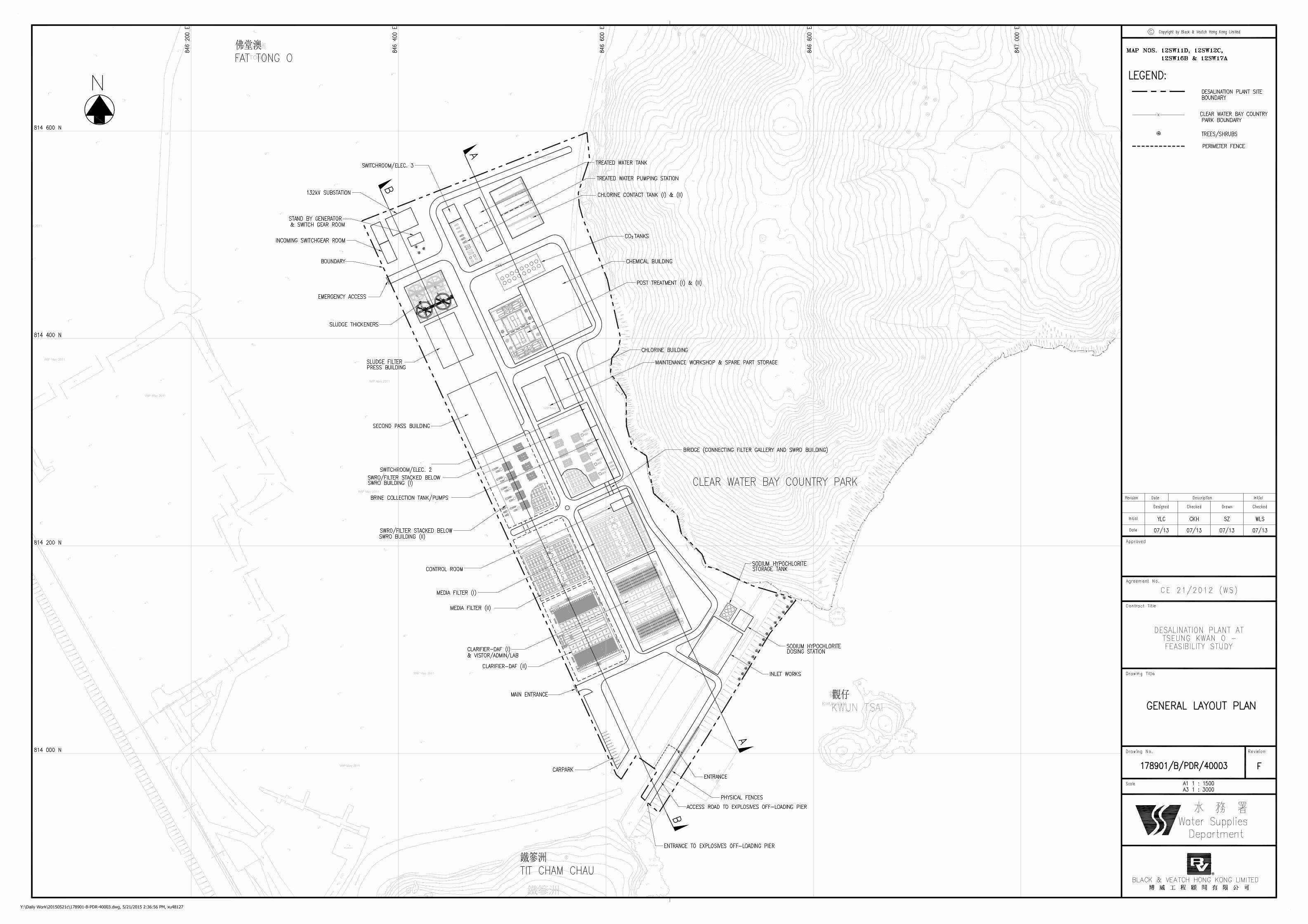
1.2.5 ThelocationofthesiteboundaryanditsassociatedfeaturesareshowninAppendixA.
1.3 PurposeandScopeofC&DMaterialManagementPlan
1.3.1 In accordance with Clause 6.25 of the Brief of Agreement, a Construction and DemolitionMaterialManagementPlan(C&DMMP)isrequiredtobepreparedforWSDagreement,CEDDVettingCommittee’sendorsement,andPublicFillCommittee’s(PFC)approval.
1.3.2 The C&DMMP shall include the disposal arrangement for marine mud from the dredgingworks,forwhichagreementfromMarineFillCommitteeofCEDDhastobesought.
1.3.3 TheC&DMMPhasbeenpreparedinaccordancewiththeguidelinesandrequirementsunderEnvironment, Transport and Works Bureau Technical Circular (Works) ETWB TCW No.33/2002“ManagementofConstructionandDemolitionMaterialincludingRock”.
1.3.4 Purposeofthisdocumentincludethefollowing:
a. Encourage proper methods of reuse, reduction, recycling, handling, storage,transportationanddisposalofconstructionanddemolition(C&D)materialgeneratedfromtheProjectasfaraspossibleandpracticable
b. Estimate the quantities of C&D material generated and their time of generation forfuturemonitoring
c. Provide information for the contractor to prepare a Waste Management Plan inconstruction
1.4 ImplementationProgramme
1.4.1 TheProjectiscurrentlyintheFeasibilityStudystage.
1.4.2 Thedetaileddesignwillbecarriedoutbetween2015and2017.
1.4.3 Construction of Desalination Plant, Phase 1, with production capacity of 135 MLD, istentativelyscheduledtocommenceinmid‐2017forcompletioninend2020.

AgreementNo.CE21/2012(WS)DesalinationPlantatTseungKwanO– 8901/B&V/0021Issue3FeasibilityStudy C&DMaterialManagementPlan
January2015 3 B&V
1.4.4 ThemainlayingofthedeliverymainistentativelyscheduledtocommenceinApril2016and,forcompletioninend2019.
1.4.5 Details of the tentative project programme are shown in Table 1‐1. This implementationprogramme reflects the schedule for the construction of the Phase1 desalinationplant. Atthistime,nodefinitiveprogrammehasbeenestablishedforexpandingthedesalinationplantto the planned ultimate capacity of 270MLD. The proposed programme for the project isshowninAppendixB.
Table 1‐1 Implementation Programme of the Project
Phase Contract No. Contract Title Date of
Commencement Date of
Completion
1 A Desalination Plant at Tseung Kwan O July 2017 October 2020
1 B Mainlaying of Delivery Main to TKOFWPSR April 2016 December 2019
2 DEVELOPMENT CONSTRAINTS
2.1 General
2.1.1 Majority of the proposed water mains will be laid by the conventional method of trenchexcavation andbackfilling.Where circumstanceswarrant, trenchless constructionmethodswillbeadoptedforthelayingoftheproposedwatermains.
2.1.2 Theproposeddesalinationplantislocatedonareclaimedlandwhichiscurrentlyservingasatemporaryfillbankareawithintheexistingtemporarygovernmentlandallocations.ThepartofthelandwillberestoredtoaprescribedlevelbeforehandingovertoWSDforconstructionworksandhencenosubstantialsiteformationisenvisaged.Whensiteworksarecommenced,conventionalconstructionmethodswillbeapplied.Theexcavationforthesub‐structureswillbe carried out by the conventional open cut and fill method with Excavation and LateralSupport system properly designed and installed. No blasting and tunneling works will beanticipatedinconstructionworkwithinthesiteboundary.
2.1.3 Thearrangement,footprintandlevelsoftanks,andlayoutofbuildingsaregovernedbytheselectedtreatmentprocessandtheassociatedhydraulics.Preliminaryconceptualsitelayoutand locationofnewbuildings tobe constructedatTKOArea137 is shown inDrawingNo.178901/B/PDR/40003inAppendixA.
2.1.4 For the design and construction of the desalination plant, there are several physicalconstraintswhicharethegoverningfactorstobeconsideredduringthedetaileddesignstage.Theseconstraintsareasfollows:
a. Trafficimpacts
b. Marinetrafficimpacts
c. Environmental considerations including air quality, noise, construction waste, waterquality,ecologyandculturalheritage
d. Utilitiesandservicesincludingwatermains,gasmains,electricity,telecommunication,drainageandsewerage
e. Projectinterfaces
AgreementNo.CE21/2012(WS)DesalinationPlantatTseungKwanO– 8901/B&V/0021Issue3FeasibilityStudy C&DMaterialManagementPlan
January2015 4 B&V
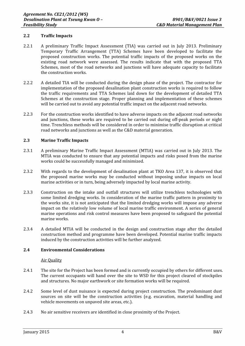
2.2 TrafficImpacts
2.2.1 A preliminary Traffic Impact Assessment (TIA) was carried out in July 2013. PreliminaryTemporary Traffic Arrangement (TTA) Schemes have been developed to facilitate theproposed construction works. The potential traffic impacts of the proposed works on theexisting road network were assessed. The results indicate that with the proposed TTASchemes,mostof theroadnetworksand junctionswillhaveadequatecapacity to facilitatetheconstructionworks.
2.2.2 AdetailedTIAwillbeconductedduringthedesignphaseof theproject.Thecontractor forimplementationoftheproposeddesalinationplantconstructionworksisrequiredtofollowthe traffic requirements andTTA Schemes laid down for the development of detailedTTASchemes at the construction stage. Proper planning and implementation of these schemeswillbecarriedouttoavoidanypotentialtrafficimpactontheadjacentroadnetworks.
2.2.3 Fortheconstructionworksidentifiedtohaveadverseimpactsontheadjacentroadnetworksand junctions, theseworks are required tobe carriedoutduringoff‐peakperiodsornighttime.TrenchlessmethodswillbeconsideredinordertominimisetrafficdisruptionatcriticalroadnetworksandjunctionsaswellastheC&Dmaterialgeneration.
2.3 MarineTrafficImpacts
2.3.1 ApreliminaryMarineTraffic ImpactAssessment (MTIA)was carriedout in July2013.TheMTIAwasconductedtoensurethatanypotential impactsandrisksposedfromthemarineworkscouldbesuccessfullymanagedandminimized.
2.3.2 Withregards to thedevelopmentofdesalinationplantatTKOArea137, it isobservedthatthe proposed marine works may be conducted without imposing undue impacts on localmarineactivitiesorinturn,beingadverselyimpactedbylocalmarineactivity.
2.3.3 Construction on the intake and outfall structures will utilize trenchless technologies withsome limiteddredgingworks. Inconsiderationof themarinetrafficpattern inproximity totheworkssite,itisnotanticipatedthatthelimiteddredgingworkswillimposeanyadverseimpactontherelatively lowvolumeof localmarinetrafficenvironment.Aseriesofgeneralmarineoperationsandriskcontrolmeasureshavebeenproposedtosafeguardthepotentialmarineworks.
2.3.4 A detailedMTIAwill be conducted in the design and construction stage after the detailedconstructionmethodandprogrammehavebeendeveloped.Potentialmarinetrafficimpactsinducedbytheconstructionactivitieswillbefurtheranalyzed.
2.4 EnvironmentalConsiderations
AirQuality
2.4.1 ThesitefortheProjecthasbeenformedandiscurrentlyoccupiedbyothersfordifferentuses.Thecurrentoccupantswillhandover the site toWSD for thisproject clearedof stockpilesandstructures.Nomajorearthworkorsiteformationworkswillberequired.
2.4.2 Some levelofdustnuisance isexpectedduringprojectconstruction.Thepredominantdustsources on site will be the construction activities (e.g. excavation, material handling andvehiclemovementsonunpavedsiteareas,etc.).
2.4.3 NoairsensitivereceiversareidentifiedincloseproximityoftheProject.
AgreementNo.CE21/2012(WS)DesalinationPlantatTseungKwanO– 8901/B&V/0021Issue3FeasibilityStudy C&DMaterialManagementPlan
January2015 5 B&V
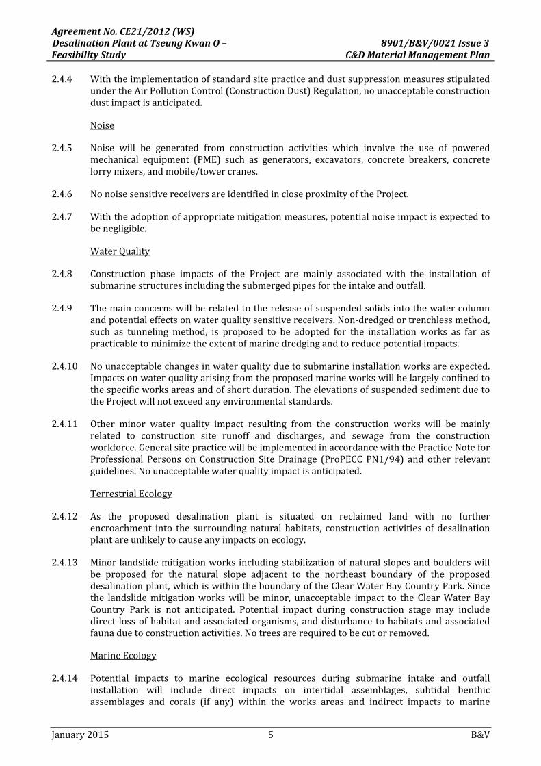
2.4.4 WiththeimplementationofstandardsitepracticeanddustsuppressionmeasuresstipulatedundertheAirPollutionControl(ConstructionDust)Regulation,nounacceptableconstructiondustimpactisanticipated.
Noise
2.4.5 Noise will be generated from construction activities which involve the use of poweredmechanical equipment (PME) such as generators, excavators, concrete breakers, concretelorrymixers,andmobile/towercranes.
2.4.6 NonoisesensitivereceiversareidentifiedincloseproximityoftheProject.
2.4.7 Withtheadoptionofappropriatemitigationmeasures,potentialnoiseimpactisexpectedtobenegligible.
WaterQuality
2.4.8 Construction phase impacts of the Project are mainly associated with the installation ofsubmarinestructuresincludingthesubmergedpipesfortheintakeandoutfall.
2.4.9 Themainconcernswillberelatedtothereleaseofsuspendedsolidsintothewatercolumnandpotentialeffectsonwaterqualitysensitivereceivers.Non‐dredgedortrenchlessmethod,such as tunneling method, is proposed to be adopted for the installation works as far aspracticabletominimizetheextentofmarinedredgingandtoreducepotentialimpacts.
2.4.10 Nounacceptablechangesinwaterqualityduetosubmarineinstallationworksareexpected.Impactsonwaterqualityarisingfromtheproposedmarineworkswillbelargelyconfinedtothespecificworksareasandofshortduration.TheelevationsofsuspendedsedimentduetotheProjectwillnotexceedanyenvironmentalstandards.
2.4.11 Other minor water quality impact resulting from the construction works will be mainlyrelated to construction site runoff and discharges, and sewage from the constructionworkforce.GeneralsitepracticewillbeimplementedinaccordancewiththePracticeNoteforProfessional Persons on Construction Site Drainage (ProPECC PN1/94) and other relevantguidelines.Nounacceptablewaterqualityimpactisanticipated.
TerrestrialEcology
2.4.12 As the proposed desalination plant is situated on reclaimed land with no furtherencroachment into the surrounding natural habitats, construction activities of desalinationplantareunlikelytocauseanyimpactsonecology.
2.4.13 Minorlandslidemitigationworksincludingstabilizationofnaturalslopesandboulderswillbe proposed for the natural slope adjacent to the northeast boundary of the proposeddesalinationplant,whichiswithintheboundaryoftheClearWaterBayCountryPark.Sincethe landslidemitigationworkswill beminor, unacceptable impact to the ClearWater BayCountry Park is not anticipated. Potential impact during construction stage may includedirect lossofhabitat andassociatedorganisms, anddisturbance tohabitatsandassociatedfaunaduetoconstructionactivities.Notreesarerequiredtobecutorremoved.
MarineEcology
2.4.14 Potential impacts to marine ecological resources during submarine intake and outfallinstallation will include direct impacts on intertidal assemblages, subtidal benthicassemblages and corals (if any) within the works areas and indirect impacts to marine

AgreementNo.CE21/2012(WS)DesalinationPlantatTseungKwanO– 8901/B&V/0021Issue3FeasibilityStudy C&DMaterialManagementPlan
January2015 6 B&V
ecological resources around themarineworks areas as a result of perturbations to waterquality.
2.4.15 Worksnearbycorals,ifany,willbeavoidedasfaraspracticaltominimizepotentialimpacts.The loss of intertidal and subtidal organisms (directly) within themarine footprint is notconsideredtorepresentanunacceptableecologicalimpact.
2.4.16 Nounacceptable impactsonwaterquality isexpectedduringproject construction. Indirectimpactstomarineecologicalresourcesarelikelytobenegligible.
Fisheries
2.4.17 Potentialimpactstofisheryresourcesandfishingoperationsmayarisefromdisturbancestothefisheryhabitatsduringmarineconstructionworksorthroughchangesinwaterqualityasaresultofthemarineconstructionworks.
2.4.18 The marine footprint of this Project is very small. The minor disturbance to fisheriesresourcesorfishingoperations,ifany,isunlikelytoresultinunacceptableimpacts.
2.4.19 ThenearestTungLungChauFishCultureZone(FCZ)islocatedatsufficientdistances(1.5km)fromtheproposedsite.Nounacceptableimpacttothissensitivereceiverisexpected.
2.5 UtilitiesandServices
2.5.1 Existingutilitiessuchasfreshwatermains,saltwatermains,stormdrains,andsewersinthevicinity of the proposed watermains alignment might be affected or temporary divertedduringconstruction.ThefeasibilityofthisarrangementwillbeinvestigatedduringthedesignphaseoftheProject.ConsentfromWSDandDSDwillbesoughtpriortotheconstruction.
2.6 ProjectInterfaces
2.6.1 CEDD
a. CEDD is currently operating a temporary fill bank facility at TKO Area137. Thetemporary facility will occupy the site until 31 December 2018 under the currentTemporaryGovernmentLandAllocation(TGLA).
b. WhileCEDDisapplyinganextension,CEDDhasagreedtohandoverthesiteclearedofstockpilefortheconstructionofthedesalinationplantbylate2015.
c. Theremay be interfaces with the operators during the site investigationworks andconstructionstage.
2.6.2 MTRCorporationLimited(MTR)
a. MTRhassetupatemporaryexplosivemagazineforitsShatintoCentralLinkandKwunTongLineExtensionprojectsattheTKOArea137.
b. Whilstthesiteforthetemporaryexplosivemagazineencroachesconsiderablyuponthereservedsiteforthedesalinationplant,thesitewillbereturnedtoWSDbylate2015fortheconstructionofthedesalinationplant.
2.6.3 TheMinesDivisionofCEDD

AgreementNo.CE21/2012(WS)DesalinationPlantatTseungKwanO– 8901/B&V/0021Issue3FeasibilityStudy C&DMaterialManagementPlan
January2015 7 B&V
a. TheMinesDivisionofCEDDisoperatingabargingpieratTKOArea137foroff‐loadingofexplosives(TGLANo.SK567).ThecurrentTGLAwillexpireon30 June2015.TheMinesDivisionplanstoapplyforanextension.
b. TheTGLANo.SK567containsaclausethatthesitewillbereturnedatanearliertimeifrequiredbyWSDfortheconstructionoftheROplantbyprovidinga6‐monthwrittennotice.
c. Thecoexistenceoftheexplosiveoff‐loadingfacilitiesandthedesalinationplantisbeingconsidered.Ahazardtolifeassessmentisbeingcarriedouttoexplorethefeasibilityofthecoexistence.
2.6.4 CLPPowerHongKongLimited(CLP)
a. CLPisplanningtoinstallahighvoltagesubmarinecableafter2020atTathongChannel.
b. Theboundaryofthecableislocatedapproximately500meterssouthofTKOArea137.NoconflictwithCLP’sproposedworkisanticipated.
2.6.5 SENTLandfillExtension
a. SENTLandfillislocateddirectlytothenorthtothedesalinationplantsite.
b. SENTLandfillExtensionwillbeconsideredasanexistingfacility.
c. Alandfillleachateandgashazardassessmentwillbecarriedout.
2.6.6 OtherProjects
a. Thereareotheron‐goingandplannedprojectssuchastheTKOCrossBayLink,TKO–Lam Tin Tunnel and Associated Works, and C&D Material Handling Facility in thevicinityofthesiteand/orTKOarea.
b. Therearesufficientseparationdistances fromtheseprojects.Cumulative impactsareunlikelytooccur.
2.6.7 NoinsurmountableinterfaceproblemisanticipatedintheProjectinviewoftheavailableandknowninterfaceprojectsabove.CloseliaisonwithcorrespondingpartieswillbemaintainedduringthecourseoftheProjecttoresolvesuchinterfaceproblems,ifany.
2.6.8 Forresolutionofpotentialconflictsandpossiblenuisancetopublicduetorepeatedroadorfootpathopeningorlongconstructionperiodarisingfromtheinterfaceissues,thefollowingmeasureswillbeadopted:
a. Entrust the proposedmainlayingworks, which are in direct conflict with the worksunderotherprojects,orviceversa.
b. Allow sufficient time in the construction contract for completion of the waterworksundertheinterfaceproject.Thecontractorsinbothprojectsshallcoordinatetheirworkprogrammesduringtheconstructionstagetoavoidrepeatedroadopening.
c. Introducetheconstructionofcommontrenchwithotherutilitylayingprojects.

AgreementNo.CE21/2012(WS)DesalinationPlantatTseungKwanO– 8901/B&V/0021Issue3FeasibilityStudy C&DMaterialManagementPlan
January2015 8 B&V
3 DEVELOPMENT OPTIONS
3.1 ConstructionofDesalinationPlant
3.1.1 In view of the treatment process, hydraulics, geotechnical and operational constraints, theconceptualdesigncomprisingthefollowingbuildings.
a. SeawaterIntakeBuilding
b. PretreatmentClarifierUnits
c. PretreatmentMediaFilterBuilding
d. SWROBuilding
e. BrineCollectionTankandPumpStation
f. UndergroundClearwaterStorageTank
g. FreshWaterPumpStation
h. ChlorineContactTank
i. ChlorineStore
j. ChemicalBuilding
k. PostTreatmentBuilding
3.1.2 The layout of the plant will be dictated by fitting the footprint of the selected treatmentprocesseswithintheproposedsiteboundary.Treatmentprocessselectionandplant layoutarecurrentlybeingdevelopedduringthecourseoftheFeasibilityStudy.
3.1.3 SincethesitewillbeclearedbyCEDDtoadesiredformationlevel, thetraditionalopencutmethodwillbeadoptedforconstructingthesubstructureoftheprocessbuildingwithproperExcavationandLateralSupportifnecessary.
3.2 ConstructionofIntakeandOutfallSystems
3.2.1 Theproposedintakeandoutfallpipeswillextendapproximately200mtotheeastandabout300to350mtothesouthfromthesiterespectively.Itisanticipatedthatsubmergedintakeandoutfallpipeswillbepreferred.
3.2.2 Trenchless installationmethod,suchas tunnellingmethod,willbeutilized tominimizeanypotentialenvironmentalimpacts.
3.2.3 Prefabricatedintakeandoutfallstructures,suchasthediffuserheads,willbetransferredandinstalledonsiteusingopen‐cutmethod.
3.2.4 Localizeddredgingworkswillbeminimizedasfaraspracticableduringconstruction.
3.3 Constructionof1200mmDiameterTrunkFeedSystem
3.3.1 TheproposedwatermainspipelayingworkswillbecarriedoutbyinstallationofExcavationandLateralSupport(ELS)system.

AgreementNo.CE21/2012(WS)DesalinationPlantatTseungKwanO– 8901/B&V/0021Issue3FeasibilityStudy C&DMaterialManagementPlan
January2015 9 B&V
3.3.2 If necessary, at critical junctions along Wan Po Road and Po Lam Road, trenchless pipejackingmethodwithmicro‐tunnelingcouldbeadopted.Pipelineswillbeadvancedthroughthegroundbyajackingstation(jackingpit)inthemainshaft.Thepipesformandactasthefinishedtunnelliner.Locationsofwheretrenchlessmethodtobeadoptedwillbedeterminedduringthedetaileddesignstage.
3.3.3 The trenchless methods will be mainly applied for water mains crossing or alongcarriageways.Trenchlesstechniqueisnotsuitableforwatermainswithmanytreebranches,valves and bends. The determination of themethod of construction will depend onmanyfactors such as site condition, construction constraints, choice of material, traffic andenvironmentalimpact,etc.
3.3.4 The proposed application of open cut method and trenchless method in the Project areconsideredtobeanoptimumdesigntakingallaspectsintoconsiderationandstrikebalanceamongtheabovedevelopmentconstraints.
3.4 SlopeStabilizationWorks
3.4.1 ThenaturalslopeoverlookingthenortheastboundaryofthenewdesalinationplantatTKOArea137hasahistoryofminorlandslidesandcontainssomepotentiallyunstableboulders.
3.4.2 Landslideandboulderhazardmitigationworksincludingmainlypassivedebrisbarriersandbouldertrapsalongthetoeofthenaturalslope,somesoilnailingatlocalsteepspotsontheslope, stabilizationof individualbouldersbybuttressinganddowellingmayberequired toprotectthenewdesalinationplantforthelandslideandboulderhazardsfromthisslope.Theproposedoptionisconsideredtobeanoptimumdesigntakingallaspectsintoconsiderationandstrikebalanceamongtheabovedevelopmentconstraints.
4 MANAGEMENT OF C&D MATERIALS
4.1 TypesofC&DMaterials
4.1.1 Constructionactivitieswill result in thegenerationof avarietyofC&Dmaterials.TheC&Dmaterials are usuallymixed consisting of inert components (public fill) such as soil, rock,concrete,brickandasphaltandnon‐inertcomponents(C&Dwaste)comprisingmetal,timber,paper,plasticandgeneralrefuse.
4.1.2 ItisexpectedthattheProjectwillresultinthegenerationofthefollowingC&Dmaterials:
a. Wastefromsiteclearance;
b. Excavated materials (soil, rock and marine sediment) from the construction ofseawater intake and outfall, foundation/ basement of desalination plant and watermains;
c. Dredgedmarine sediments from the construction of seawater intake and outfall anddesalinationplant;
d. Construction and demolition (C&D)material from construction of newbuildings andcivilstructures;
e. Chemicalwastefrommaintenanceofconstructionplantandequipment;and
f. Generalrefusefromthesiteworkforce

AgreementNo.CE21/2012(WS)DesalinationPlantatTseungKwanO– 8901/B&V/0021Issue3FeasibilityStudy C&DMaterialManagementPlan
January2015 10 B&V
4.1.3 ThenaturalslopeoverlookingthenortheastboundaryofthenewdesalinationplantatTKOArea137hasahistoryofminorlandslidesandcontainssomepotentiallyunstableboulders.Landslideandboulderhazardmitigationworksincludingmainlypassivedebrisbarriersandbouldertrapsalongthetoeofthenaturalslope,somesoilnailingatlocalsteepspotsontheslope, stabilizationof individualbouldersbybuttressinganddowellingmayberequired toprotect the new desalination plant for the landslide and boulder hazards from this slope.Therewillnotbeanytreeremovalandexcavationworks.
4.1.4 TheCEDDiscurrentlyoperatingatemporaryfillbankatTKOArea137,whichisstockpiledorfilledwithinertC&Dmaterialswithaccessroadsbetweenvariouspartsofthesite.Thesitewillbeoccupiedbythetemporaryfillbankuntilendof2018.CEDDhasagreedtohandoverthe 10 ha site cleared of stockpile for this Project by late 2015. Thus the quantity of siteclearancewaste(egvegetation)isexpectedtobesmall.
4.2 QuantitiesofC&DMaterials
4.2.1 As the plant is located on a flat reclaimed land without any existing buildings and slopecutting works, the quantity of C&D materials generated from the construction would beexpectedtobelowerthanconventionalsiteofthesameplantscale.
4.2.2 Some of the excavated materials and earthworks will be utilized on‐site as backfill. Theunsuitableexcavatedmaterials,whicharenotsuitableforreuse,willbedisposedoff‐site.ApreliminaryestimationoftotalvolumeofexcavatedmaterialslikelytobegeneratedfromtheProjectworks,basedontheconceptuallayoutofthedesalinationplant,isgiveninTable4‐2andTable4‐2.DetailedestimationisenclosedinAppendixC.
Table 4‐1 Cut and Fill Requirement of the Seawater Intake & Outfall, Desalination Plant and Mains Laying
Location Excavated Material Generated
from Construction Works (m3)
Excavated
Materials Suitable
for on‐site Filling (m3)
Fill Requirement
s (m3)
Filled Material
s Reused on
Site (m3)
Surplus Excavate
d Materials Disposedof at Fill Bank as Public Fill
(m3)
Surplus Excavated Materials Disposed of at Landfill
as Construction Waste (m3)
Surplus Excavate
d Materials Disposed
of as Marine Sediments (m3)
Seawater Intake
785 550 905 550 79 0 157
Seawater Outfall
402 402 4,320 402 0 0 0
Desalination Plant
(included slope mitigation works)
183,776 118,896 0 0 180,173 2,744 859
Mains Laying
42,733 29,444 25,961 25,961 16,404 368 ‐
Total 227,696 149,292 31,186 26,913 196,656 3,112 1,016
AgreementNo.CE21/2012(WS)DesalinationPlantatTseungKwanO– 8901/B&V/0021Issue3FeasibilityStudy C&DMaterialManagementPlan
January2015 11 B&V
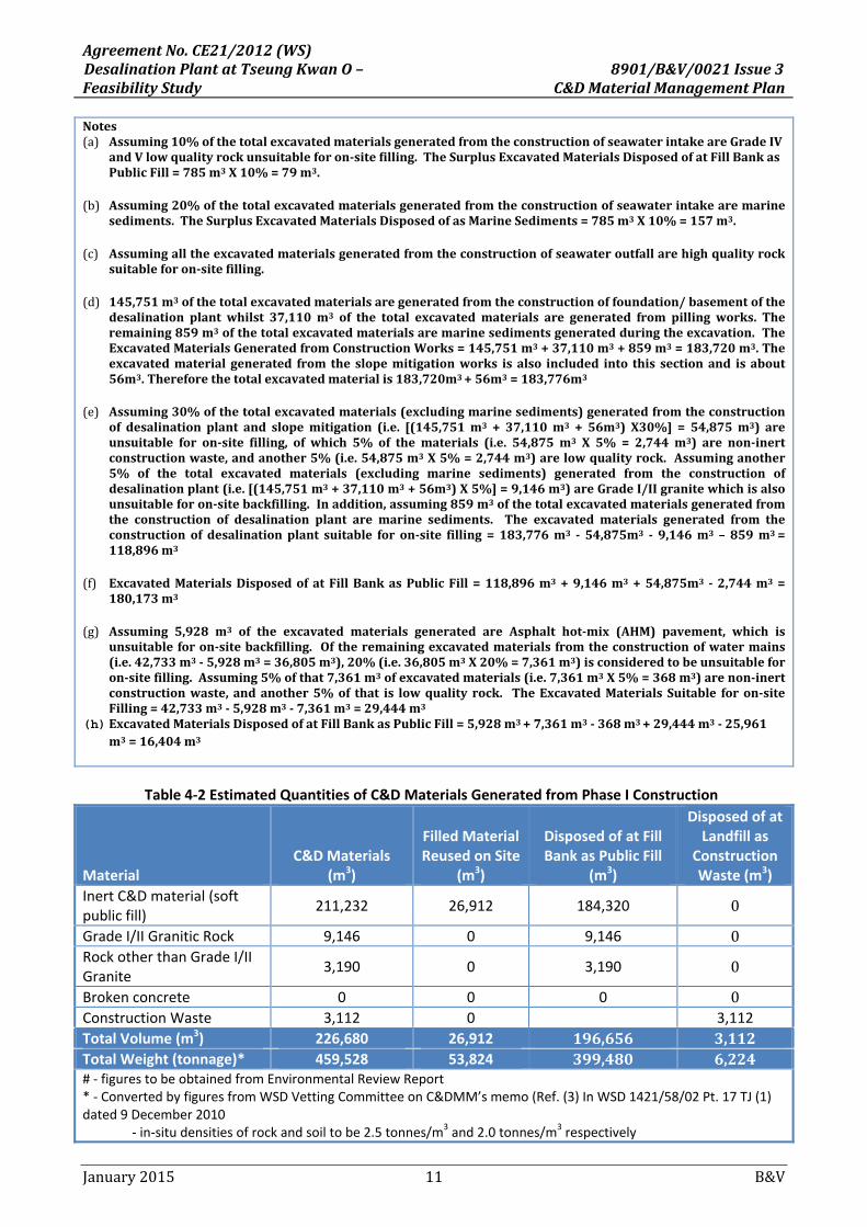
Notes(a) Assuming10%ofthetotalexcavatedmaterialsgeneratedfromtheconstructionofseawaterintakeareGradeIV
andVlowqualityrockunsuitableforon‐sitefilling.TheSurplusExcavatedMaterialsDisposedofatFillBankasPublicFill=785m3X10%=79m3.
(b) Assuming20%ofthetotalexcavatedmaterialsgeneratedfromtheconstructionofseawaterintakearemarinesediments.TheSurplusExcavatedMaterialsDisposedofasMarineSediments=785m3X10%=157m3.
(c) Assumingalltheexcavatedmaterialsgeneratedfromtheconstructionofseawateroutfallarehighqualityrocksuitableforon‐sitefilling.
(d) 145,751m3ofthetotalexcavatedmaterialsaregeneratedfromtheconstructionoffoundation/basementofthedesalination plantwhilst 37,110m3 of the total excavatedmaterials are generated from pillingworks. Theremaining859m3ofthetotalexcavatedmaterialsaremarinesedimentsgeneratedduringtheexcavation.TheExcavatedMaterialsGeneratedfromConstructionWorks=145,751m3+37,110m3+859m3=183,720m3.Theexcavatedmaterialgenerated from the slopemitigationworks isalso included into this sectionand isabout56m3.Thereforethetotalexcavatedmaterialis183,720m3+56m3=183,776m3
(e) Assuming30%ofthetotalexcavatedmaterials(excludingmarinesediments)generatedfromtheconstructionof desalination plant and slopemitigation (i.e. [(145,751m3 + 37,110m3 + 56m3)X30%] = 54,875m3) areunsuitable for on‐site filling, ofwhich 5% of thematerials (i.e. 54,875m3 X 5% = 2,744m3) are non‐inertconstructionwaste,andanother5%(i.e.54,875m3X5%=2,744m3)arelowqualityrock. Assuminganother5% of the total excavated materials (excluding marine sediments) generated from the construction ofdesalinationplant(i.e.[(145,751m3+37,110m3+56m3)X5%]=9,146m3)areGradeI/IIgranitewhichisalsounsuitableforon‐sitebackfilling.Inaddition,assuming859m3ofthetotalexcavatedmaterialsgeneratedfromthe construction of desalination plant aremarine sediments. The excavatedmaterials generated from theconstructionofdesalinationplant suitable foron‐site filling=183,776m3 ‐54,875m3 ‐9,146m3 –859m3=118,896m3
(f) ExcavatedMaterialsDisposedofatFillBankasPublicFill=118,896m3+9,146m3+54,875m3 ‐2,744m3=180,173m3
(g) Assuming 5,928 m3 of the excavated materials generated are Asphalt hot‐mix (AHM) pavement, which isunsuitableforon‐sitebackfilling. Oftheremainingexcavatedmaterialsfromtheconstructionofwatermains(i.e.42,733m3‐5,928m3=36,805m3),20%(i.e.36,805m3X20%=7,361m3)isconsideredtobeunsuitableforon‐sitefilling.Assuming5%ofthat7,361m3ofexcavatedmaterials(i.e.7,361m3X5%=368m3)arenon‐inertconstructionwaste,andanother5%of that is lowqualityrock. TheExcavatedMaterialsSuitable foron‐siteFilling=42,733m3‐5,928m3‐7,361m3=29,444m3
(h) ExcavatedMaterialsDisposedofatFillBankasPublicFill=5,928m3+7,361m3‐368m3+29,444m3‐25,961m3=16,404m3
Table 4‐2 Estimated Quantities of C&D Materials Generated from Phase I Construction
Material C&D Materials
(m3)
Filled Material Reused on Site
(m3)
Disposed of at Fill Bank as Public Fill
(m3)
Disposed of at Landfill as
Construction Waste (m3)
Inert C&D material (soft public fill)
211,232 26,912 184,320 0
Grade I/II Granitic Rock 9,146 0 9,146 0Rock other than Grade I/II Granite
3,190 0 3,190 0
Broken concrete 0 0 0 0Construction Waste 3,112 0 3,112
Total Volume (m3) 226,680 26,912 196,656 3,112Total Weight (tonnage)* 459,528 53,824 399,480 6,224# ‐ figures to be obtained from Environmental Review Report* ‐ Converted by figures from WSD Vetting Committee on C&DMM’s memo (Ref. (3) In WSD 1421/58/02 Pt. 17 TJ (1) dated 9 December 2010 ‐ in‐situ densities of rock and soil to be 2.5 tonnes/m3 and 2.0 tonnes/m3 respectively
AgreementNo.CE21/2012(WS)DesalinationPlantatTseungKwanO– 8901/B&V/0021Issue3FeasibilityStudy C&DMaterialManagementPlan
January2015 12 B&V
Material C&D Materials
(m3)
Filled Material Reused on Site
(m3)
Disposed of at Fill Bank as Public Fill
(m3)
Disposed of at Landfill as
Construction Waste (m3)
‐ densities of imported rock and soil to be 2.0 tonnes/m3 and 1.8 tonnes/m3 respectively ‐ density of in‐situ marine dredged sediment to be 2.2 tonnes/m3
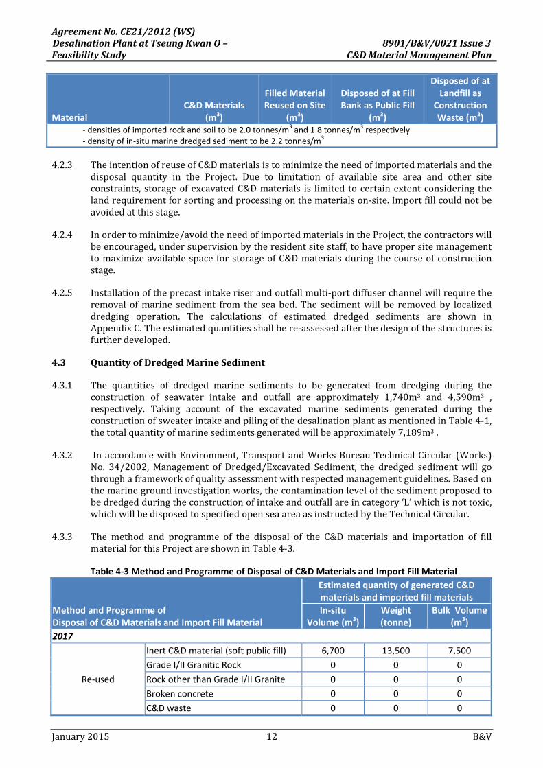
4.2.3 TheintentionofreuseofC&Dmaterialsistominimizetheneedofimportedmaterialsandthedisposal quantity in the Project. Due to limitation of available site area and other siteconstraints, storageof excavatedC&Dmaterials is limited tocertainextentconsidering thelandrequirementforsortingandprocessingonthematerialson‐site.Importfillcouldnotbeavoidedatthisstage.
4.2.4 Inordertominimize/avoidtheneedofimportedmaterialsintheProject,thecontractorswillbeencouraged,undersupervisionbytheresidentsitestaff,tohavepropersitemanagementtomaximizeavailablespace forstorageofC&Dmaterialsduringthecourseofconstructionstage.
4.2.5 Installationoftheprecastintakeriserandoutfallmulti‐portdiffuserchannelwillrequiretheremoval ofmarine sediment from the sea bed. The sedimentwill be removed by localizeddredging operation. The calculations of estimated dredged sediments are shown inAppendixC.Theestimatedquantitiesshallbere‐assessedafterthedesignofthestructuresisfurtherdeveloped.
4.3 QuantityofDredgedMarineSediment
4.3.1 The quantities of dredged marine sediments to be generated from dredging during theconstruction of seawater intake and outfall are approximately 1,740m3 and 4,590m3 ,respectively. Taking account of the excavated marine sediments generated during theconstructionofsweaterintakeandpilingofthedesalinationplantasmentionedinTable4‐1,thetotalquantityofmarinesedimentsgeneratedwillbeapproximately7,189m3.
4.3.2 InaccordancewithEnvironment,TransportandWorksBureauTechnicalCircular(Works)No. 34/2002, Management of Dredged/Excavated Sediment, the dredged sediment will gothroughaframeworkofqualityassessmentwithrespectedmanagementguidelines.Basedonthemarinegroundinvestigationworks,thecontaminationlevelofthesedimentproposedtobedredgedduringtheconstructionofintakeandoutfallareincategory‘L’whichisnottoxic,whichwillbedisposedtospecifiedopenseaareaasinstructedbytheTechnicalCircular.
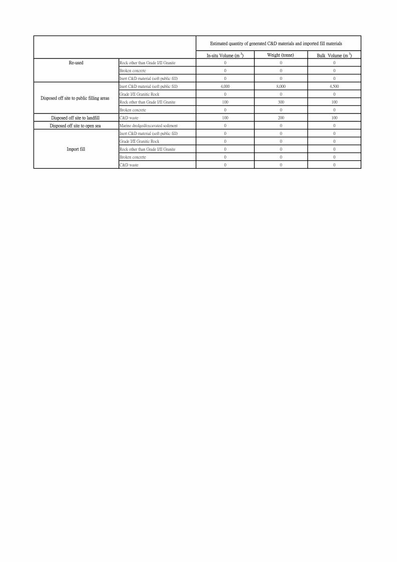
4.3.3 The method and programme of the disposal of the C&D materials and importation of fillmaterialforthisProjectareshowninTable4‐3.
Table 4‐3 Method and Programme of Disposal of C&D Materials and Import Fill Material
Method and Programme of Disposal of C&D Materials and Import Fill Material
Estimated quantity of generated C&D materials and imported fill materials
In‐situ Volume (m3)
Weight (tonne)
Bulk Volume (m3)
2017
Re‐used
Inert C&D material (soft public fill) 6,700 13,500 7,500
Grade I/II Granitic Rock 0 0 0
Rock other than Grade I/II Granite 0 0 0
Broken concrete 0 0 0
C&D waste 0 0 0

AgreementNo.CE21/2012(WS)DesalinationPlantatTseungKwanO– 8901/B&V/0021Issue3FeasibilityStudy C&DMaterialManagementPlan
January2015 13 B&V
Method and Programme of Disposal of C&D Materials and Import Fill Material
Estimated quantity of generated C&D materials and imported fill materials
In‐situ Volume (m3)
Weight (tonne)
Bulk Volume (m3)
Disposed off site to public filling areas
Inert C&D material (soft public fill) 60,100 120,200 67,300
Grade I/II Granitic Rock 3,000 7,600 3,400
Rock other than Grade I/II Granite 1,000 2,600 1,100
Broken concrete 0 0 0
Disposed off site to landfill
C&D waste 1,000 2,100 1,200
Disposed off site to open sea
Marine dredged sediment 3,600 7,900 4,000
Import fill
Inert C&D material (soft public fill) 2,100 4,300 2,400
Grade I/II Granitic Rock 0 0 0
Rock other than Grade I/II Granite 0 0 0
Broken concrete 0 0 0
C&D waste 0 0 0
2018
Re‐used
Inert C&D material (soft public fill) 6,700 13,500 7,500
Grade I/II Granitic Rock 0 0 0
Rock other than Grade I/II Granite 0 0 0
Broken concrete 0 0 0
C&D waste 0 0 0
Disposed off site to public filling areas
Inert C&D material (soft public fill) 60,100 120,200 67,300
Grade I/II Granitic Rock 3,000 7,600 3,400
Rock other than Grade I/II Granite 1,000 2,600 1,100
Broken concrete 0 0 0
Disposed off site to landfill
C&D waste 1,000 2,100 1,200
Disposed off site to open sea
Marine dredged sediment 3,600 7,900 4,000
Import fill
Inert C&D material (soft public fill) 2,100 4,300 2,400
Grade I/II Granitic Rock 0 0 0
Rock other than Grade I/II Granite 0 0 0
Broken concrete 0 0 0
C&D waste 0 0 0
2019
Re‐used
Inert C&D material (soft public fill) 6,700 13,500 7,500
Grade I/II Granitic Rock 0 0 0
Rock other than Grade I/II Granite 0 0 0
Broken concrete 0 0 0
C&D waste 0 0 0
Disposed off site to public filling areas
Inert C&D material (soft public fill) 60,100 120,200 67,300
Grade I/II Granitic Rock 3,000 7,600 3,400
Rock other than Grade I/II Granite 1,000 2,600 1,100

AgreementNo.CE21/2012(WS)DesalinationPlantatTseungKwanO– 8901/B&V/0021Issue3FeasibilityStudy C&DMaterialManagementPlan
January2015 14 B&V
Method and Programme of Disposal of C&D Materials and Import Fill Material
Estimated quantity of generated C&D materials and imported fill materials
In‐situ Volume (m3)
Weight (tonne)
Bulk Volume (m3)
Broken concrete 0 0 0
Disposed off site to landfill
C&D waste 1,000 2,100 1,200
Disposed off site to open sea
Marine dredged sediment 0 0 0
Import fill
Inert C&D material (soft public fill) 0 0 0
Grade I/II Granitic Rock 0 0 0
Rock other than Grade I/II Granite 0 0 0
Broken concrete 0 0 0
C&D waste 0 0 0
2020
Re‐used
Inert C&D material (soft public fill) 6,700 13,500 7,500
Grade I/II Granitic Rock 0 0 0
Rock other than Grade I/II Granite 0 0 0
Broken concrete 0 0 0
Inert C&D material (soft public fill) 0 0 0
Disposed off site to public filling areas
Inert C&D material (soft public fill) 4,000 8,000 4,500
Grade I/II Granitic Rock 0 0 0
Rock other than Grade I/II Granite 100 300 100
Broken concrete 0 0 0
Disposed off site to landfill
C&D waste 100 200 100
Disposed off site to open sea
Marine dredged sediment 0 0 0
Import fill
Inert C&D material (soft public fill) 0 0 0
Grade I/II Granitic Rock 0 0 0
Rock other than Grade I/II Granite 0 0 0
Broken concrete 0 0 0
C&D waste 0 0 0
Remarks: 1. The detailed programme and more accurate quantities of the disposal works will depend on the contractor’s
programme after the contract is awarded.
2. All the figures are rounded to the nearest 100 cubic metre or tonne.
4.4 Generation,ReuseandRecycleofC&DMaterials
4.4.1 WaystominimizethegenerationofC&Dmaterialinclude:
a. Layoutandleveloftheproposedworksshouldbeproperlydesigned.
b. Programmingofworksshouldbewelldefined.
c. Liaisonshouldbestrengthenedbetweenrelevantsupervisingofficersandsiteworkerstominimizeerrorsinconstructiontoavoidunnecessaryexcavation.

AgreementNo.CE21/2012(WS)DesalinationPlantatTseungKwanO– 8901/B&V/0021Issue3FeasibilityStudy C&DMaterialManagementPlan
January2015 15 B&V
d. All site staff and contractors should work together to avoid and minimize thegenerationofC&Dmaterialduringconstruction.
e. Good sitemanagement should bemaintained on site tominimize over ordering andcrosscontamination.
f. Working method/arrangement should be reviewed to minimize wastage wherepossible.
g. Steelformworkshouldbeusedasfaraspossible.
4.4.2 WaytomaximizetheuseofinertC&Dmaterialincludes:
a. Theuseofrecycledaggregatesforconcreteshouldbefullyutilized.
4.4.3 WaystomaximizethereuseofC&Dmaterialincludingsoilorrockonsiteinclude:
a. Excavatedsoftspoilfrommainlayingtrenchesshouldbere‐usedasfillmaterialasfaraspossibletominimizeoff‐sitedisposal.
b. Sortingshouldbecarriedoutonsiteor indesignatedsortingareaandseparateC&Dmaterial into public fill and C&Dwaste, and sorting of C&Dmaterial by category tofacilitatereuse/recycling/return.
c. The concrete/brick/aggregates shouldbebrokenup into suitable size for general fillmaterial.
d. Goodconditiontimbershouldbereusedseveraltimes.
e. Remainingreusablewoodenmaterialshouldbesortedandusedatotherconstructionsitesbythesamecontractororsoldtootherconstructionsites.
f. Contractor should reuse or recycle construction/demolition waste with recyclablevalues such as reinforcement bars, steel mesh etc. These wastes should either bereusedonsiteorcollectedbyoutsidelicensedwasterecyclingagents.
4.4.4 WaystomaximizetheuseofrecycledC&Dmaterialinclude:
a. Dryconcretewasteshouldbesortedout fromotherwastesandrecycledatrecyclingplanttoformaggregatesforroadsub‐base.
b. Paper/cardboard,metal, others (e.g. plastic, foamboard etc) shouldbe collected anddeliveredtolocalrecyclingfactories.
4.4.5 Wheretheconstructionprocessproduceschemicalwaste,thecontractormustregisterwithEPD as a chemical waste producer. Storage, handling, transport and disposal of chemicalwasteshouldbearrangedinaccordancewiththeCodeofPracticeonthePackaging,LabellingandStorageofChemicalWasteissuedbyEPD.
4.4.6 Any unused chemicals or those with remaining functional capacity should be recycled.Chemicalwasteshouldbecollectedbylicensedcontractorfordisposalatalicensedchemicalwastetreatmentfacility.
4.4.7 Inconstructionstage, thecontractorshouldprepareandsubmitaWasteManagementPlan(WMP)aspartoftheEnvironmentalManagementPlan(EMP)forapprovalbytheEngineerin

AgreementNo.CE21/2012(WS)DesalinationPlantatTseungKwanO– 8901/B&V/0021Issue3FeasibilityStudy C&DMaterialManagementPlan
January2015 16 B&V
accordancewithETWBTCWNo. 19/2005. TheEMP shoulddescribe the arrangements foravoidance,reuse,recovery,recycling,storage,collection,treatmentanddisposalofdifferentcategoriesofC&Dmaterialsgeneratedfromtheconstructionactivities.ThecontractorshallimplementthewastemanagementpracticesintheEMPthroughouttheconstructionstageoftheProject.
4.4.8 The contractor should refer and strictly follow the trip‐ticket system in accordance withDEVBTCWNo.6/2010toensureallC&Dmaterialsaredisposedofproperly.
4.4.9 Inaddition,WSDwillconductsiteinspectiontomonitorthecontractors’performanceintheimplementationoftheEMPandotherrelevantspecifiedrequirements.
5 FINDINGS AND RECOMMENDATIONS
5.1 SummaryofFindings
5.1.1 ThisC&DMMPsummarizestheexpectedquantitiesofgrossandsurpluswasteslikelytoarisefrom the implementation of the Project and feasibleways tominimize, re‐use, recycle andappropriatelydisposeof surplusC&Dmaterials.The intentionof reuseofC&Dmaterials istominimizetheneedofimportedmaterialsintheProject.
5.1.2 Dueto limitationofavailablesiteareaandothersiteconstraints,storageofexcavatedC&Dmaterials is limited to certain extent considering the land requirement for sorting andprocessingonthematerialson‐site.Importfillcouldnotbeavoided.
5.2 SummaryofRecommendations
5.2.1 Inorder tominimize/avoidtheneedof importedmaterials in theProject, thecontractorsshall be encouraged,under supervision by the Resident SiteStaff,to have proper sitemanagementtomaximizeavailablespaceforstorageofC&Dmaterialsduringthecourseofconstructionstage.
5.2.2 The management measures to be adopted for C&D materials can be enforced byincorporatingthemintoaWasteManagementPlan(WMP)aspartofthecontractdocument.Environmentalmonitoringandauditwillbenecessarytoensuretheproperimplementationoftheproposedmeasuresduringconstruction.
5.2.3 If appropriate management measures are implemented properly during the handling,collection and disposal of C&D materials, the residual environmental impacts would bereducedtoacceptablelevels.
5.2.4 In accordance with the requirements stipulated in the ETWB TC(W) No. 33/2002, it isrecommendedthattheProjectOfficeandtheConsultantshouldmonitortheimplementationof thisC&DMMPandpreparehalfyearlystatus reportandsubmit toPublicFillCommittee(PFC) for their information. The requirements of the status report are detailed in theTechnicalCircular.
5.2.5 It is recommended that this C&DMMP be reviewed and updated regularly by the ProjectOffice, the Consultant and the contractor throughout the Project. If there is any significantincreaseinamountofinertand/ornon‐inertmaterialstobedisposedoffsite,theplanshouldberevisedandre‐submittedforendorsement.
5.2.6 The contractorwill be providedwith information from the C&DMMP in order to facilitatetheminthepreparationoftheWMP,whichisrequiredundertheEnvironmental,Transport

AgreementNo.CE21/2012(WS)DesalinationPlantatTseungKwanO– 8901/B&V/0021Issue3FeasibilityStudy C&DMaterialManagementPlan
January2015 17 B&V
andWorksBureauTechnicalCircular(Works)No.19/2005–EnvironmentalManagementonConstructionSites.AspartoftheWMP,thecontractorshallestablishamechanismtorecordthequantitiesofC&DmaterialsgeneratedeachmonthandreportthequantitiestotheProjectOffice. In addition, the contractor shall provide estimated quantities of C&Dmaterials thatwillbegeneratedeachyearfromthesite.ThecontractorisalsorequiredtosetupdisposalrecordingsystemaspartoftheWMPbyadoptingthetrip‐ticketsystemasstipulatedinDEVBTC(W)No.6/2010,inordertoensureproperdisposalofC&Dmaterialsatdesignatedoutlets.
ENDOFTEXT

AgreementNo.CE21/2012(WS)DesalinationPlantatTseungKwanO–FeasibilityStudy
8901/B&V/0021Issue3C&DMaterialManagementPlan
January2015 B&V
AppendixA
AgreementNo.CE21/2012(WS)DesalinationPlantatTseungKwanO–FeasibilityStudy
8901/B&V/0021Issue3C&DMaterialManagementPlan
January2015 B&V
AppendixB
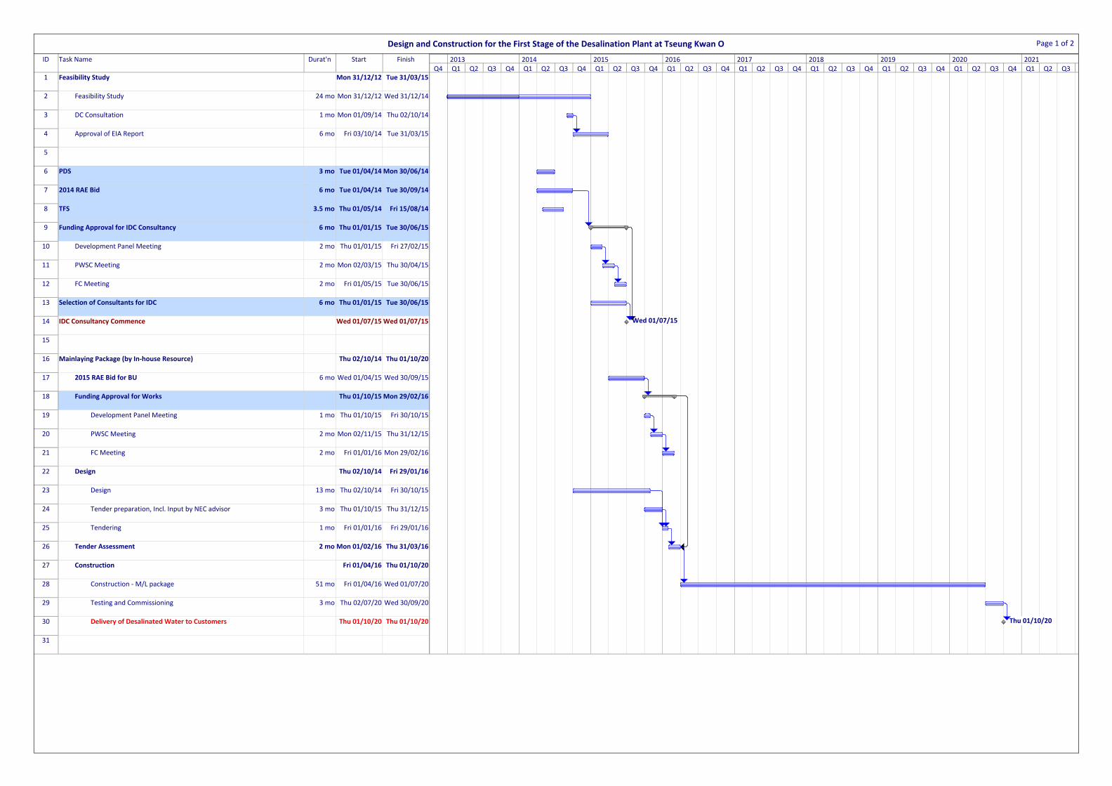
ID Task Name Durat'n Start Finish
1 Feasibility Study Mon 31/12/12 Tue 31/03/15
2 Feasibility Study 24 mo Mon 31/12/12 Wed 31/12/14
3 DC Consultation 1 mo Mon 01/09/14 Thu 02/10/14
4 Approval of EIA Report 6 mo Fri 03/10/14 Tue 31/03/15
5
6 PDS 3 mo Tue 01/04/14 Mon 30/06/14
7 2014 RAE Bid 6 mo Tue 01/04/14 Tue 30/09/14
8 TFS 3.5 mo Thu 01/05/14 Fri 15/08/14
9 Funding Approval for IDC Consultancy 6 mo Thu 01/01/15 Tue 30/06/15
10 Development Panel Meeting 2 mo Thu 01/01/15 Fri 27/02/15
11 PWSC Meeting 2 mo Mon 02/03/15 Thu 30/04/15
12 FC Meeting 2 mo Fri 01/05/15 Tue 30/06/15
13 Selection of Consultants for IDC 6 mo Thu 01/01/15 Tue 30/06/15
14 IDC Consultancy Commence Wed 01/07/15 Wed 01/07/15
15
16 Mainlaying Package (by In‐house Resource) Thu 02/10/14 Thu 01/10/20
17 2015 RAE Bid for BU 6 mo Wed 01/04/15 Wed 30/09/15
18 Funding Approval for Works Thu 01/10/15 Mon 29/02/16
19 Development Panel Meeting 1 mo Thu 01/10/15 Fri 30/10/15
20 PWSC Meeting 2 mo Mon 02/11/15 Thu 31/12/15
21 FC Meeting 2 mo Fri 01/01/16 Mon 29/02/16
22 Design Thu 02/10/14 Fri 29/01/16
23 Design 13 mo Thu 02/10/14 Fri 30/10/15
24 Tender preparation, Incl. Input by NEC advisor 3 mo Thu 01/10/15 Thu 31/12/15
25 Tendering 1 mo Fri 01/01/16 Fri 29/01/16
26 Tender Assessment 2 moMon 01/02/16 Thu 31/03/16
27 Construction Fri 01/04/16 Thu 01/10/20
28 Construction ‐ M/L package 51 mo Fri 01/04/16 Wed 01/07/20
29 Testing and Commissioning 3 mo Thu 02/07/20 Wed 30/09/20
30 Delivery of Desalinated Water to Customers Thu 01/10/20 Thu 01/10/20
31
Wed 01/07/15
Thu 01/10/20
Q4 Q1 Q2 Q3 Q4 Q1 Q2 Q3 Q4 Q1 Q2 Q3 Q4 Q1 Q2 Q3 Q4 Q1 Q2 Q3 Q4 Q1 Q2 Q3 Q4 Q1 Q2 Q3 Q4 Q1 Q2 Q3 Q4 Q1 Q2 Q32013 2014 2015 2016 2017 2018 2019 2020 2021
Design and Construction for the First Stage of the Desalination Plant at Tseung Kwan O Page 1 of 2

ID Task Name Durat'n Start Finish
32 Approval of EIA Report 6 mo Fri 03/10/14 Tue 31/03/15
33 Desalination Plant (Design‐and‐Build) Thu 02/07/15 Thu 01/10/20
34 2016 RAE Bid for BU 6mo Fri 01/04/16 Fri 30/09/16
35 Funding Approval for Works Mon 02/01/17 Fri 30/06/17
36 Development Panel Meeting 2 mo Mon 02/01/17 Tue 28/02/17
37 PWSC Meeting 2 mo Wed 01/03/17 Fri 28/04/17
38 FC Meeting 2 mo Mon 01/05/17 Fri 30/06/17
39 Pre‐Design‐and‐Build Thu 02/07/15 Fri 30/12/16
40 Investigation Review 2 mo Thu 02/07/15 Mon 31/08/15
41 Further Site Investigation 8 mo Tue 01/09/15 Fri 29/04/16
42 CAF/Land Allocation 15 mo Tue 01/09/15 Thu 01/12/16
43 OZP amendment 12 mo Thu 31/12/15 Fri 30/12/16
44 Prepration of Hazard Assessment, Planning Study and Action Plan 2 mo Mon 03/08/15 Wed 30/09/15
45 CCPHI Submission 3 mo Thu 01/10/15 Wed 30/12/15
46 SOA Approval 8 mo Mon 02/11/15 Thu 30/06/16
47 FSRO Gazettal 12 mo Tue 01/09/15 Wed 31/08/16
48 GEO Submission 4 mo Tue 01/09/15 Thu 31/12/15
49 Country Park Authority Approval 4 mo Fri 01/01/16 Mon 02/05/16
50 Reference Design 13 mo Tue 01/09/15 Fri 30/09/16
51 DC Consultation 1 mo Thu 01/09/16 Fri 30/09/16
52 Prequalification of Contractors Tue 01/09/15Wed 31/08/16
53 Prepare Prequal Doc 6 mo Tue 01/09/15 Tue 01/03/16
54 Conduct Prequalification 6 mo Wed 02/03/16 Wed 31/08/16
55 Tender Mon 03/10/16 Fri 30/06/17
56 Tendering 4 mo Mon 03/10/16 Tue 31/01/17
57 Tender Assessment 5 mo Wed 01/02/17 Fri 30/06/17
58 Construction (Design‐and‐Build) Mon 03/07/17Wed 30/09/20
59 Design Submissions ‐ AIP 8 mo Mon 03/07/17 Wed 28/02/18
60 Design Submissions ‐ DDA 12 mo Mon 02/10/17 Fri 28/09/18
61 Construction 30 mo Wed 03/01/18 Wed 01/07/20
62 Testing and Commissioning 3 mo Fri 03/07/20 Wed 30/09/20
63 Delivery of Desalinated Water to Customers (DB) Thu 01/10/20 Thu 01/10/20 Thu 01/10/20
Q4 Q1 Q2 Q3 Q4 Q1 Q2 Q3 Q4 Q1 Q2 Q3 Q4 Q1 Q2 Q3 Q4 Q1 Q2 Q3 Q4 Q1 Q2 Q3 Q4 Q1 Q2 Q3 Q4 Q1 Q2 Q3 Q4 Q1 Q2 Q32013 2014 2015 2016 2017 2018 2019 2020 2021
Design and Construction for the First Stage of the Desalination Plant at Tseung Kwan O Page 2 of 2

AgreementNo.CE21/2012(WS)DesalinationPlantatTseungKwanO– 8901/B&V/0021Issue3FeasibilityStudy C&DMaterialManagementPlan
January2015 2 B&V
AppendixC

Average Diameter = 1,200 mm
Trench width = 2,400 mm
Assumed Depth of Trench = 2.2 m
Length of open cut = 7,600 m
Length of trenchless section = 1,900 m
Thickness of Pavement = 0.3 m
Total volume of AHM (pavement) = 7,600 x ( 2.4 + 0.2 ) x 0.3
(assume average 300mm thick) = 5,928 m3
1.22 x PI
4
= 36,805 m3
Assume 20% of unsuitable material = 20% x 36,805
= 7,361 m3
Assume 5% as non-inert C&D
waste from 25% of unsuitable
material
= 5% x 7,361
= 368 m3
Assume 5% as low quality rock
from 25% of unsuitable material= 5% x 7,361
= 368 m3
Total volume of material can be
used as backfill= 36,805 - 7,361
= 29,444 m3
1.22 x PI
4
= 25,961 m3
Backfill material in excess = 29,444 - 25,961
= 3,483 m3
Therefore:
(i) Total volume excavated = 5,928 + 36,805 = 42,733 m3
(ii) Volume reuse on site = 25,961 m3
(iii) Volume import to site = 0 m3
(iv) Volume delivery to public fill = 5,928 + ( 7,361 - 368 ) + 3,483 = 16,404 m3
(i) Volume disposal at landfill = 368 m3
DN 1200 Pipe for 9km water main
2.4 x
Total Volume of excavation (trench
and trenchless)= 7,600 x ( 2.2 - 0.3 ) x 2.4
-36,805=Total backfill material needed 7,600-x
1,900 x+
0.3 x9,500

Average Diameter = 1,800 mm
Drilling width = 2,000 mm
Length of intake = 250 m
22 x PI
4
= 785 m3
About 20% of marine sediment = 20% x 785
= 157 m3
Assume 10% as low quality rock (Grade IV and
V)= 10% x 785
= 79 m3
Total volume of granular material can be used as
backfill= 785 - 236
= 550 m3
Backfill material in excess = 550 - 0
= 550 m3
Therefore,
(i) Total volume excavated = 785 + 1,583 = 2,369 m3
(ii) Volume reuse on site = 550 m3
(iii) Volume import to site = 355 m3
(iv) Volume delivery to public fill = 79 m3
(i) Volume disposal at landfill = 0 m3
With dredging:
Assuming offshore precast intake screeing units
will be installed with size=
= x 6 = 679 m3
1
3
= 1,583 m3
Total volume of sediment can be re-used = 0 m3
Backfill left from above pipeline excavation = 550 m3
Extra backfill to be imported = 905 - 550 = 355 m3
(ii) Volume reuse on site(as above) = 550 m3
(iii) Volume import to site(as above) = 355 m3
(vi) Volume disposal at to open sea = 1,740 m3 say 1800m3
]x H [
Pipe for 250m intake (Phase I & II)
Total Volume of excavation (trenchless)
(granular)250 x (=
Based on the Geological Profile along the proposed alignment of Intake in Site Investigation Report (8901/B&V/0034)
Based on the Marine GI result at the proposed dredging area sediment shows no contamination, therefore,
)
122 + (12x6) + 62
Area of intake screen x Depth
113
= 905 m3
Volume of dredging with 45o inclination = x PI
Granular Fill required to fill the void at the sides
of the riser= 1,583 - 679

Average Diameter = 1,500 mm
Drilling width = 1,600 mm
Length of outfall = 200 m
1.62 x PI
4
= 402 m3
Assume 100% high quality rock = 100% x 402
= 402 m3
Total volume of granular material can be used as
backfill= 402 - 0
= 402 m3
Backfill material in excess = 402 - 0
= 402 m3
Therefore,
(i) Total volume excavated = 402 + 4590 = 4992 m3
(ii) Volume reuse on site = 402 m3
(iii) Volume import to site = 3918 m3
(iv) Volume delivery to public fill = 0 m3
(i) Volume disposal at landfill = 0 m3
With dredging:
Assume Multi-port diffuser to be used,
with diffuser length = 153 m
1
2
= 4,590 m3
Total volume of sediment can be re-used = 0 m3
1.52 x PI
4
Backfill left from above pipeline excavation = 402 m3
Extra backfill to be imported = 4,320 - 402 = 3,918 m3
(ii) Volume reuse on site(as above) = 402 m3
(iii) Volume import to site(as above) = 3,918 m3
(vi) Volume disposal at to open sea = 4,590 m3
= 4,320 m3
4 x
= m3
Granular Fill required to fill the void at the sides of
the diffuser tubes
Assuming diffuser pipe with diameter 1500mm to
be used, volume of tubes= x 153
= 4,590 - 270
270
Volume of dredging with 45o inclination = x (12+3) x 153
DN1500 Pipe for 350m outfall (Phase I & II)
Total Volume of excavation (trenchless) (granular) = 200 x ( )
Based on the Geological Profile along the proposed alignment of Intake in Site Investigation Report (8901/B&V/0034)
Based on the Marine GI result at the proposed dredging area sediment shows no contamination, therefore,

Page 1 of 2
Building/ Facility (3) Length(m) Width(m) Area(m2)
BelowGround Level
(m)Foundation excavation(m) Volume of excavation(m3)
Incoming Switcher Room 40 10 400 0 2 800
132kV Substation 36 18 648 0 2 1,296Chemical Building 78 45 3,510 0 2 7,020Maintenance Workshop 34 13 442 0 2 884Standby Generator & Switchgear Room 9 9 81 0 2 162Sodium Hypohclorite Storage Tanks 20 14 280 0 2 560Sodium Hypohclorite Dosing Station 17 12 204 0 2 408Visitor/ Admin/ Lab 36 29 1,044 0 2 2,088Clarifier (I) 77 56 4,312 0 2 8,624Media Filter (I) + Control Room 60 56 3,360 3 2 16,800
SWRO/ Filter Stacked below SWRO Building (I) 104 55 5,720 6 2 45,760
Chlorine Storage (I) and (II) 82 34 2,788 0 2 5,576Sludge Thinkeners 39 39 1,521 0 2 3,042Sludge Filter Press Building 47 35 1,645 0 2 3,290Post Treatment (I) 35 29 1,015 0 2 2,030Chlorine Contact Tank (I) 34 25 850 9 2 9,350Inlet Pumping Station 46 33 1,518 12 2 21,252Treated Water Pumping Station 61 13 793 11 2 10,309
Underground Clear Water Storage Tank (I) 25 20 500 11 2 6,500
Total 145,751
Volume of excavation for bore-piles
Total volume = 1/4 x 22 x π x 40 x 210
= 37110 m3
Volume of excavation for soil-nailAssuming a total no. of 517 nos. of soil nails are need for slope mitigation works with the size about 0.6 x 0.6 x 0.3
Total Volume = 0.6 x 0.6 x 0.3 x 517
= 56 m3
Total volume of excavation = 145,751 + 37,110 + 56
= 182,917 m3
Note:
1. All Dimensions measured from Drawing No. 178901/B/PDR/40003)
2. The underground clear water storage tank is 11m deep in the ground.
3. All buildings are assumed to be built on deeper(2m thick) base slab to enchance spreading of loads.
Plant Site
Assuming a total no. of 210 bore piles are needed for whole plant, with 2.5m diameter and 40m depth,

Page 2 of 2
Total volume of excavation = 182,917 m3
Assume 30% of unsuitable material = 30% x 182,917= 54,875 m3
= 2,744 m3
= 2,744 m3
Assume 5% of total excavation as Grade I/ II
Granite during pilling= 9,146 m3
= 118,896 m3
Total backfill material needed = 0 m3
Backfill material in excess = 118,896 - 0= 118,896 m3
Therefore:(i) Total volume excavated = 182,917 m3
(ii) Volume reuse on site = 0 m3
(iii) Volume import to site = 0 m3
(iv) Volume delivery to public fill = 182,917 - 2,744 = 180,173 m3
(i) Volume disposal at landfill = 2,744
Thickness of layer = 7 m
No. of pile impacted = 25 nos.
Volume of marine sediment will be
excavated= 859 m3
x 54,875
5% x 54,875
5%
Based on the Geological Profile of the Site Area in Site Investigation Report (8901/B&V/0034), a layer of marine clay is identifed at the northern boundary of the site and may excavate during the pilling works
Based on the Geological Profile of the Site Area in Site Investigation Report (8901/B&V/0034)
=Total volume of material can be used as backfill
Plant Site
Assume 5% as non-inert C&D waste from 30%
of unsuitable material=
=Assume 5% as low quality rock from 30% of
unsuitable material
- 9,14654,875-182,917

C&D Material Management - Baseline Quantities for Desalination Plant Phase I
Mainlaying Intake & Outfall Plant Site Total2017 2018 2019 2020
Gross total C&D Material Generated
(a) Inert C&D material (soft public fill) 41,997 952 168,284 211,232 66,832 66,832 66,832 10,737
(b) Grade I/II Granitic Rock 0 0 9,146 9,146 3,049 3,049 3,049 0
(c) Rock other than Grade I/ II Granite 368 79 2,744 3,190 1,026 1,026 1,026 112
(d) Broken concrete 0 0 0 0 0 0 0 0
(e) C&D waste 368 0 2,744 3,112 1,007 1,007 1,007 92
(f) Marine dredged sediment 0 6,330 1,016 7,346 3,673 3,673 0 042,733 7,361 183,933 75,586 75,586 71,913 10,941
18% 3% 79% 32% 32% 31% 5%Surplus C&D Material Generated
(Gross Total minus Reuse on Site):(a) Inert C&D material (soft public fill) 16,036 0 168,284 184,320 60,104 60,104 60,104 4,009
(b) Grade I/II Granitic Rock 0 0 9,146 9,146 3,049 3,049 3,049 0
(c) Rock other than Grade I/ II Granite 368 79 2,744 3,190 1,026 1,026 1,026 112
(d) Broken concrete 0 0 0 0 0 0 0 0
(e) C&D waste 368 0 2,744 3,112 1,037 1,037 1,037 92
(f) Marine dredged sediment 0 6,330 1,016 7,346 3,673 3,673 0 016,772 6,409 183,933 68,889 68,889 65,216 4,213
8% 3% 89% 37% 33% 31% 2%Imported Fill Material:
(a) Inert C&D material (soft public fill) 0 4,273 0 4,273 2,136 2,136 0 0
(b) Rock (excluding armour) - - - NIL - - - -
(c) Sand fill - - - NIL - - - -0 4,273 0 2,136 2,136 0 0
0% 100% 0% 50% 50% 0% 0%
Notes and assumptions:
1. Construction of water mains will be evenly distributed from 2017 to 2020.
2. Excavation work of site plan will be done by 2018, assuming 50% of excavation will be done in 2017 and in 2018 respectively.
3. The existing area for plant site formation are formed by reclamation of public fill.
4. In the plant site excavation materials, 10% are Grade I/ II Granite from pilling works.
5. No broken concrete will be generated form the whole construction phase.
Year
Total
Total
Total 234,026
207,114
4,273
Baseline Quantity (m3)

C&D Materials Reused Disposed
(m3) on Site off Site
(m3) (m3)
Phase I
Inert C&D material (soft public fill) 211,232 26,912 184,320
Grade I/II Granitic Rock 9,146 0 9,146
Rock other than Grade I/II Granite 3,190 0 3,190
Broken concrete 0 0 0
C&D waste 3,112 0 3,112
Total Volume (m3) 226,680 26,912 199,768
Total Weight (tonnage)* 475,345 53,824 405,704
in-situ densities of rock and soil to be 2.5 tonnes/m3 and 2.0 tonnes/m3 respectively
densities of imported rock and soil to be 2.0 tonnes/m3 and 1.8 tonnes/m3 respectively
* - Converted by figures from WSD Vetting Committee on C&DMM’s memo (Ref. (3) In WSD 1421/58/02 Pt. 17 TJ (1) dated 9 December 2010
(Note: Round up figures of bulk volume used)
Material
Table 1. Estimated Quantities of Different C&D Materials Generated

In-situ Volume (m3) Weight (tonne) Bulk Volume (m
3)
Inert C&D material (soft public fill) 6,700 13,500 7,500
Grade I/II Granitic Rock 0 0 0
Rock other than Grade I/II Granite 0 0 0
Broken concrete 0 0 0
C&D waste 0 0 0
Inert C&D material (soft public fill) 60,100 120,200 67,300
Grade I/II Granitic Rock 3,000 7,600 3,400
Rock other than Grade I/II Granite 1,000 2,600 1,100
Broken concrete 0 0 0
Disposed off site to landfill C&D waste 1,000 2,100 1,200
Disposed off site to open sea Marine dredged/excavated sediment 3,600 7,900 4,000
Inert C&D material (soft public fill) 2,100 4,300 2,400
Grade I/II Granitic Rock 0 0 0
Rock other than Grade I/II Granite 0 0 0
Broken concrete 0 0 0
C&D waste 0 0 0
Inert C&D material (soft public fill) 6,700 13,500 7,500
Grade I/II Granitic Rock 0 0 0
Rock other than Grade I/II Granite 0 0 0
Broken concrete 0 0 0
C&D waste 0 0 0
Inert C&D material (soft public fill) 60,100 120,200 67,300
Grade I/II Granitic Rock 3,000 7,600 3,400
Rock other than Grade I/II Granite 1,000 2,600 1,100
Broken concrete 0 0 0
Disposed off site to landfill C&D waste 1,000 2,100 1,200
Disposed off site to open sea Marine dredged/excavated sediment 0 0 0
Inert C&D material (soft public fill) 0 0 0
Grade I/II Granitic Rock 0 0 0
Rock other than Grade I/II Granite 0 0 0
Broken concrete 0 0 0
C&D waste 0 0 0
Inert C&D material (soft public fill) 6,700 13,500 7,500
Grade I/II Granitic Rock 0 0 0
Table 2 Method and Programme of Disposal of C&D Materials and Import of Fill Material(Rounded to nearest hundredth place)
0
Estimated quantity of generated C&D materials and imported fill materials
2017
Re-used
Disposed off site to public filling areas
Import fill
C&D waste 0 0
2018
Re-used
Disposed off site to public filling areas
Import fill
2019
Re-used
Disposed off site to public filling areas
Import fill
2020
In-situ Volume (m3) Weight (tonne) Bulk Volume (m
3)
Estimated quantity of generated C&D materials and imported fill materials
Rock other than Grade I/II Granite 0 0 0
Broken concrete 0 0 0
Inert C&D material (soft public fill) 0 0 0
Inert C&D material (soft public fill) 4,000 8,000 4,500
Grade I/II Granitic Rock 0 0 0
Rock other than Grade I/II Granite 100 300 100
Broken concrete 0 0 0
Disposed off site to landfill C&D waste 100 200 100
Disposed off site to open sea Marine dredged/excavated sediment 0 0 0
Inert C&D material (soft public fill) 0 0 0
Grade I/II Granitic Rock 0 0 0
Rock other than Grade I/II Granite 0 0 0
Broken concrete 0 0 0
C&D waste 0 0 0
Import fill
Re-used
Disposed off site to public filling areas