agreement on international roads in the … on international roads in the ... need to increase...
TRANSCRIPT

AGREEMENT ON INTERNATIONAL ROADS IN THE ARAB MASHREQ
UNITED NATIONS 2001

– 2 –
The Parties to the present Agreement, conscious of the importance of facilitating land transport on international roads in the Arab Mashreq and the need to increase cooperation and intraregional trade and tourism through the formulation of a well-studied plan for the construction and development of an international road network that satisfies both future traffic needs and environmental requirements, have agreed as follows:
Article 1 Adoption of the International Road Network
The Parties hereto adopt the international road network described in Annex I to this Agreement (the “Arab Mashreq International Road Network”), which includes roads that are of international importance in the Arab Mashreq and should therefore be accorded priority in the establishment of national plans for the construction, maintenance and development of the national road networks of the Parties hereto.
Article 2 Orientation of the routes of the International
Road Network The Arab Mashreq International Road Network consists of the main routes having a north/south and east/west orientation and may include other roads to be added in the future, in conformity with the provisions of this Agreement.
Article 3 Technical specifications
Within a maximum period of fifteen (15) years, all roads described in Annex I shall be brought into conformity with the technical specifications described in Annex II to this Agreement. New roads built after the entry into force of this Agreement shall be designed in accordance the technical specifications defined in the said Annex II.
Article 4 Signs, signals and markings
Within a maximum period of seven (7) years, the signs, signals and markings used on all roads described in Annex I shall be brought into conformity with the standards defined in Annex III hereto. New signs, signals and markings produced after the entry into force of this Agreement shall be designed in accordance with the technical standards defined in the said Annex III.
– 3 –
Article 5 Signature, ratification, acceptance, approval
and accession 1. This Agreement shall be open to members of the Economic and Social Commission for Western Asia (ESCWA) for signature at United Nations House in Beirut, from 10 May 2001 to 31 December 2002. 2. The members referred to in paragraph 1 in this article may become Parties to the present Agreement by:
(a) Signature not subject to ratification, acceptance or approval (i.e., definitive signature);
(b) Signature subject to ratification, acceptance or approval, followed
by ratification, acceptance or approval; or (c) Accession.
3. Ratification, acceptance, approval or accession shall be effected by the deposit of an instrument with the depositary. 4. States other than ESCWA members may become Parties to the Agreement, subject to the approval of all the ESCWA members parties thereto, by depositing an instrument of accession with the depositary.
Article 6 Entry into force
1. The Agreement shall enter into force ninety (90) days after the date on which five (5) members of ESCWA have either signed it definitively or deposited an instrument of ratification, acceptance, approval or accession. 2. For each member of ESCWA referred to in paragraph 1 of Article 5 signing the Agreement definitively or depositing an instrument of ratification, acceptance or approval thereof or accession thereto after the date on which five members of ESCWA have either signed it definitively or de posited such an instrument, the Agreement shall enter into force ninety (90) days after the date of that member’s definitive signature or deposit of the instrument of ratification, approval, acceptance or accession. For each State other than a member of ESCWA depositing an instrument of accession the Agreement shall enter into force ninety (90) days after the date of that State’s deposit of that instrument.

– 4 –
Article 7 Amendments
1. After the entry of the Agreement into force, any Party thereto may propose amendments to the Agreement, including its Annexes. 2. Proposed amendments to the Agreement shall be submitted to the Committee on Transport of the Economic and Social Commission for Western Asia (ESCWA). 3. Amendments to the Agreement shall be considered adopted if approved by a two -thirds majority of the Parties thereto, present at a meeting convened for that purpose. In the case of amendments to Annex I to the Agreement, such majority must include all Parties directly concerned by the proposed amendment. 4. The Committee on Transport of ESCWA shall inform the depositary, within a period of forty-five (45) days, of any amendment adopted pursuant to paragraph 3 of this article. 5. The depositary shall notify all Parties hereto of amendments thus adopted, which shall enter into force for all Parties three (3) months after the date of such notification unless objections from more than one -third of the Parties are received by the depositary within that period of three (3) months. 6. No amendments may be made to the Agreement during the period specified in Article 8 below if, upon the withdrawal of one party, the number of Parties to the Agreement becomes less than five (5).
Article 8 Withdrawal
Any Party may withdraw from this Agreement by written notification addressed to the depositary. Such withdrawal shall take effect twelve (12) months after the date of deposit of the notification unless revoked by the Party prior to the expiration of that period.
Article 9 Termination
This Agreement shall cease to be in force if the number of Parties thereto is less than five (5) during any period of twelve (12) consecutive months.

– 5 –
Article 10 Dispute settlement
1. Any dispute arising between two or more Parties to this Agreement which relates to its interpretation or application and which the Parties to the dispute have been unable to resolve by negotiation or other means of settlement shall be referred to arbitration if any Party so requests. In such a case the dispute shall be submitted to an arbitral tribunal to which each of the Parties shall appoint one member, and the members thus appointed shall agree on the appointment of a president of the arbitral tribunal from outside their number. If no agreement is reached concerning the appointment of the president of the arbitral tribunal within three (3) months from the request for arbitration, any Party may request the Secretary-General of the United Nations, or whomever he delegates, to appoint a president of the tribunal, to which the dispute shall be referred for decision. 2. The Parties to the dispute shall be bound by the decision to form the arbitral tribunal pursuant to paragraph 1 of this article and by any and all awards handed down by the tribunal. The Parties further undertake to defray the costs of arbitration.
Article 11 Limits of application of the Agreement
Nothing in this Agreement shall be construed as preventing a Party hereto from taking any action that it considers necessary to its external or internal security or its interests, provided that such action is not contrary to the provisions of the Charter of the United Nations.
Article 12 Depositary
The Secretary-General of the United Nations shall be the depositary of the Agreement.
Article 13 Annexes and list of technical terms
The three Annexes to the Agreement and the list of technical terms used therein are integral parts of the Agreement.
IN WITNESS WHEREOF, the undersigned, being duly authorized thereto, have signed this Agreement.
DONE at Beirut, this 10 May 2001, in the Arabic, English and French languages, all of which are equally authentic.

– 6 –
ARABIC, FRENCH, AND ENGLISH TECHNICAL TERMS USED (Listed in the alphabetical order of the Arabic terms)
Traffic Signal Feux de signalisation ÅÔÇÑÉ ãÑæÑ ÖæÆíÉ
Priority over oncoming
traffic
Priorité à la circulation
qui arrive
ÃæáæíÉ Úáì ÇáãÑæÑ
ÇáÞÇÏã
Superelevation Superélévation ÇáÑÝÚ ÇáÌÇäÈí
Convergence of traffic stream Convergence du flux de
la circulation
ÇäÏãÇÌ ÍÑßÇÊ ÇáãÑæÑ
Horizontal alignment Alignement horizontal ÊÎØíØ ÃÝÞí
Vertical alignment Alignement vertical Ê Î Ø í Ø ÑÃÓí
Divergence of traffic stream Divergence du flux de la
circulation
ÊÝÑÚ ÍÑßÇÊ ÇáãÑæÑ
Intersection Intersection ÊÞÇØÚ
Roundabout Rond-point ÊÞÇØÚ Ðæ ÌÒíÑÉ ÏÇÆÑíÉ
(ÏæÇÑ)
At-grade Intersection Croisement au niveau du
sol
ÊÞÇØÚ Úáì ãÓÊæì
æÇÍÏ
Interchange Echangeur ÊÞÇØÚ ãÊÚÏÏ
ÇáãÓÊæíÇÊ
Median Médiane ÌÒíÑÉ æÓØíÉ
Bridge Pont ÌÓÑ
Truss Poteau ÌãÇáæä
Guardrail Barrière de protection ÍÇÌÒ ÇáÍãÇíÉ
Traffic volume Densité de la circulation ÍÌã ÇáãÑæÑ
Design Hourly Volume
(DHV)
Densité de la Circulation
par Conception Horaire
(DCCH)
ÍÌã ÇáãÑæÑ ááÓÇÚÉ
ÇáÊÕãíãíÉ
Right of Way Droit de Passage ÍÑã ÇáØÑíÞ
Band Bande ÍÒãÉ
Mountainous terrain Terrain montagneux ØÈíÚÉ ÇáÃÑÖ ÌÈáíÉ
Rolling terrain Terrain onduleux ØÈíÚÉ ÇáÃÑÖ ãÊãæÌÉ
Level terrain Terrain plat ØÈíÚÉ ÇáÃÑÖ ãÓÊæíÉ
Critical length Longueur critique Øæá ÍÑÌ
Pavement Marking Signalisation de la
chaussée
ÚáÇãÉ ÓØÍ ÇáØÑíÞ
Vertical (overhead) Clearance Déblaiement vertical ÝÓÍÉ ÑÃÓíÉ

– 7 –
Shoulder (s) Epaule (s) ß Ê Ý (ÃßÊÇÝ)
Code (s) Code (s) ßæÏ (ÃßæÇÏ)
Sign Panneau áÇÝÊÉ
“GIVE WAY” Sign Panneau “cédez la
priorité”
áÇÝÊÉ "Êãåá" (ÅÝÓÇÍ
ÇáØÑíÞ)
“End of Prohibition or
Restriction” Sign
Panneau “Fin de
l’interdiction ou la
restriction”
áÇÝÊÉ "äåÇíÉ ÇáÞíÏ
æÇáÍÙÑ"
Mandatory Sign Panneau obligatoire áÇÝÊÉ ÅÌÈÇÑíÉ
Informative Sign Panneau instructif áÇÝÊÉ ÅÑÔÇÏíÉ
Direction Sign Panneau de direction áÇÝÊÉ ÇáÇÊÌÇå
Warning Sign Panneau avertisseur áÇÝÊÉ ÊÍÐíÑíÉ
Regulatory Sign Panneau régulateur áÇÝÊÉ ÊäÙíãíÉ
Road Number Sign Panneau de numéro de la
route
áÇÝÊÉ ÑÞã ÇáØÑíÞ
Advance Direction Sign Panneau de direction
avancé
áÇÝÊÉ ãÊÞÏãÉ ááÇÊÌÇå
Average Daily Traffic (ADT) Moyenne de la Densité
de la Circulation (MDC)
ãÊæÓØ ÍÌã ÇáãÑæÑ
Çáíæãí
Passing distance Distance de dépassement ãÓÇÝÉ ÇáÊÎØí
Stopping distance Distance d’arrêt ãÓÇÝÉ ÇáÊæÞÝ
Sight distance Distance de vision ãÓÇÝÉ ÇáÑÄíÉ
Level of service Niveau de service ãÓÊæì ÇáÎÏãÉ
Lane Voie ãÓÑÈ (ÍÇÑÉ)
Acceleration and deceleration
lane
Voie d’accélération et de
ralentissement
ãÓÑÈ ÇáÊÓÇÑÚ
æÇáÊÈÇØÄ
Slip road Voie de déviation ãÓÑÈ ÇáÊÝÑÚ
Left Turn Lane Voie de deviation à
gauche
ãÓÑÈ ÇáÏæÑÇä ááíÓÇÑ
Speed Change Lane Voie de changement de
vitesse
ãÓÑÈ ÊÛííÑ ÇáÓÑÚÉ
Climbing lane Voie d’ascension ãÓÑÈ ÕÚæÏ
Rate of curvature Courbe moyenne ãÚÏá ÊÛíÑ ÇáÇäÍäÇÁ
Weaving Section Section d’entrelacement ãÞØÚ ÇáÊäÇÓÌ

– 8 –
Cross section Section transversale ãÞØÚ ÚÑÖí
Transition Curve Virage de transition ã ä Í ä ì ÇäÊÞÇáí
Vertical grade Pente verticale ã í á Ø æ á í (ÑÃÓí)
Cross slope Pentes transversales ã í á Ú Ñ Ö í
Traffic Control Device Dispositifs de contrôle
de la circulation
æÓíáÉ ÇáÊÍßã ÇáãÑæÑí
For the definitions of these terms and those contained in the body of the agreement and its annexes one may refer to those annexes and the road specification codes and manuals of the countries of the region, such as the Egyptian, Jordanian and Saudi Arabian codes, and also the American code as described in the publication of the American Association of State Highway and Transportation Officials (AASHTO).

– 9 –
ANNEXES TO THE AGREEMENT
A. ANNEX I: ARAB MASHREQ INTERNATIONAL ROAD NETWORK
1. North-south routes (a) M5 Iraq, East Arabian Peninsula Zakho (Iraq/Turkey) – Mosul – Baghdad – Al Samawah – Basrah – Safwan (Iraq/Kuwait) – Abdally (Kuwait/Iraq) – Kuwait – Nuwayseeb (Kuwait/Saudi Arabia) – Khafji (Saudi Arabia/Kuwait) – Abu Hadriyah (Dammam – Hufuf – Salwa)* – Batha’a (Saudi Arabia/United Arab Emirates) – Al Ghweifat (United Arab Emirates/ Saudi Arabia) – Abu Dhabi – Dubai – Fujairah – Kalba (United Arab Emirates/Oman) – Khatmat Malahaw (Oman/ United Arab Emirates) – Sohar – Muscat – Nizwa – Thumrayt – Salalah. (b) M7 Abu Dhabi-Sohar
Abu Dhabi – Al Ayn – Buraimi (United Arab Emirates/Oman) – Buraimi (Oman/ United Arab Emirates) – Sohar. (c) M9 Al Ayn-Nizwa
Al Ayn – Mazyad (United Arab Emirates/Oman) – Hafit (Oman/ United Arab Emirates) – Nizwa. (d) M15 Aleppo-Ramadi
Aleppo – Deir Ez Zor – Albu Kamal (Syria/Iraq) – Al kaem – (Iraq/Syria) – Ramadi. (e) M25 Petroleum Pipeline
Hadithat – Ar’ar – Hafar El Batin – Abu Hadriyah. (f) M35 Middle Arabian peninsula
Amman – Al Azraq – Omari (Jordan/Saudi Arabia) – Hadithat (Saudi Arabia/Jordan) – Sakakah – Ha’il – Buraydah – Riyadh – Al Kharj. (g) M45 Syria-Jordan-Saudi Arabia-Yemen
Bab Al Hawa (Syria/Turkey) – Aleppo – Homs – Damascus – Nasib (Syria/Jordan) – Jaber (Jordan/Syria) – Amman – Ma’an – Al Mudawara (Jordan/Saudi Arabia) – Halat Ammar (Saudi Arabia/Jordan) – Tabuk – Qalibah – Medina – Mecca – Abha – Elb (Saudi Arabia/Yemen) – Baqim (Yemen/Saudi Arabia) – Sana’a – Ta’izz.
* This section will eventually be replaced by the coastal ro ad (Dammam – Salwa) upon its completion.

– 10 –
(h) M47 Ma’an-Aqaba
Ma’an – Aqaba. (i) M51 Eastern Mediterranean Coast
Kassab – Lattakia – Tartous – Dabboussieh (Syria/Lebanon) – Abboudieh (Lebanon/Syria) – Tripoli – Beirut – Naqoura. (j) M55 Sinai – East Red Sea
Arish – Nakhel – Nuweiba – Aqaba – Ad Durra (Jordan/Saudi Arabia) – Ad Durra (Saudi Arabia/Jordan) – Dhuba – Yanbu – Rabigh – Jeddah – Darb – Al Tuwal (Saudi Arabia/Yemen) – Harad (Yemen/Saudi Arabia) – Hodeidah – Al Mukha. (k) M65 Red Sea-West Coast
Ismailia – Suez – Safaga – Halayeb (Egypt/Sudan). (l) M67 East Delta Kantara Bridge – Ismailia – Cairo. (m) M75 Nile Valley Alexandria – Cairo – Qena – Arqine (Egypt/Sudan).
2. East-west routes (a) M10 Northern Iraq-East Mediterranean Hajj Omran (Iraq/Iran) – Irbil – Mosul – Rabieyyah (Iraq/Syria) – Yaaroubia (Syria/Iraq) – Kamishli – Aleppo – Lattakia. (b) M20 Central Syria Kamishli – Hasakah – Deir Ez Zor – Homs – Tartus. (c) M30 Western Iraq-Eastern Mediterranean Al Rutbah – Al Walid (Iraq/Syria) – Tanf (Syria/Iraq) – Damascus – Jedeidet Yabus (Syria/Lebanon) – Masna’ (Lebanon/Syria) – Beirut.

– 11 –
(d) M40 Iraq, Jordan, Occupied Palestinian Territory and Mediterranean Southern Coast Munthareya (Iraq/Iran) – Khanaqin – Baghdad – Ramadi – Al Rutbah – Tarabil (Iraq/Jordan) – Karamah (Jordan/Iraq) – Al Azraq – Amman – King Hussein Bridge (Jordan/Occupied Palestinian Territory) – Jerusalem – Gaza – Rafah (Egypt/Occupied Palestinian Territory) – Arish – Kantara Bridge – Port Said – Alexandria – Salum (Egypt/Libya). (e) M50 Baghdad-Cairo Baghdad – Karbala – Al Nukhaib – Jedeidat Ar’ar (Iraq/Saudi Arabia) – Jedeidat Ar’ar (Saudi Arabia/Iraq) – Ar’ar – Sakakah – Qalibah – Tabuk – Ad Durra (Saudi Arabia/Jordan) – Ad Durra (Jordan/Saudi Arabia) – Aqaba – Nuweiba – Nakhel – Shatt – Cairo. (f) M60 Western Saudi Arabia-Upper Egypt Dhuba – Safaga – Qena – Mutt. (g) M70 Kuwait-Yanbu* Kuwait – As Salmy (Kuwait/Saudi Arabia) – Ar Ruqi (Saudi Arabia/Kuwait) – Hafar El Batin – Artawiyah – Buraydah – Medina – Yanbu. (h) M80 Manama-Jeddah Manama – King Fahd Bridge (Bahrain /Saudi Arabia) – Dammam – Riyadh – Mecca – Jeddah. (i) M90 Doha-Ad Darb Doha – Abu Samra (Qatar/Saudi Arabia) – Salwah (Saudi Arabia/Qatar) – Batha’a (Saudi Arabia/United Arab Emirates) – Harad – Al Kharj – Sulayyil – Abha – Ad Darb. (j) M100 Southern Arabian Peninsula Thumrayt – Mazyounah (Oman/Yemen) – Shahan (Yemen/Oman) – Gheizah – Al Mukalla – Aden – Ta’izz – Al Mukha.
* Eventually a section will be added upon being completed, branching off from this route at Artawiyah and
heading east to Jubayl via A’bu Hadriyah.

– 12 –
B. ANNEX II: TECHNICAL SPECIFICAT IONS TO BE MET ON ROUTES IN THE ARAB MASHREQ INTERNATIONAL ROAD NETWORK
Table 1 gives the technical specifications to be met on routes in the Arab Mashreq road network. The following is a detained description of those specifications.
1. General remarks
To ensure traffic safety, the protection of the environment, the smooth flow of traffic and user comfort, all parts of the routes mentioned in annex I and roads to be added to the international network must satisfy the conditions laid down hereinafter. All members undertake to use their best efforts to comply with the provisions of this annex both in building new roads and in upgrading existing roads.
2. Classification of international roads
Roads in the Arab Mashreq International Road Network shall be classified as follows: (a) First-class freeways: roads basically for use by motor vehicles of various types and on which use by bicycles and pedestrians is prohibited. These are dual-carriageway highways divided by a median, on which access is fully controlled by having all their intersections on different levels (interchanges) and having vehicles enter and exit via ramps at a limited number of points, in a manner that does not affect the flow of traffic. (b) First-class expressways: dual-carriageway highways which are divided by a median and on which access is partially controlled by means of high-efficiency at-grade intersections, while interchanges may be used at certain points, taking into account considerations of safety and accident prevention. Access should be confined to a limited number of exit and entry points, and special lanes should be provided for changing speed and turning at intersections. On such roads, the direct entry and exit of vehicles to and from adjacent roads and establishments is prohibited. (c) Second-class roads: roads designed to be medium-sized in keeping with the intended volume of traffic on them, affording an appropriate travelling speed. They consist of two lanes, one for each direction, not separated by a median strip. Intersections on such roads are at-grade. Interchanges, however, may be used when necessary. Roads of this type may be used only where there exist land availability constraints or financing is inadequate. Priority should be accorded to upgrading this type.

– 13 –
TABLE 1. TECHNICAL SPECIFICATIONS TO BE MET ON THE ROUTES OF THE ARAB MASHREQ INTERNATIONAL ROAD NETWORK
No. Specification Draft agreement (December 2000) Remarks
1 Road classification First-class freeways First-class expressways
Second-class roads
2 Description Dual-divided Dual-divided Single-carriageway
3 Degree of access control
Total (grade- separated intersections)
Partial/total (at -grade/grade-
separated
intersections)
Partial (at -grade/garde-separated intersections)
- These are the actual specifications of the American Association of State Highway and Transportation Officials (AASHTO). However, the names of the classes have been changed. In addition, no fourth class has been included as in the case of the
Asian network, inasmuch as that class has modest characteristics that make it unsuitable for qualification as an international road.
- The reason for adding the “freeway” class to those proposed in the study by
the Council of Arab Ministers of Transport is to increase the efficiency of the international system, inasmuch as that class has excellent speed and safety characteristics and will help reduce traffic congestion and transport costs while
improving highway safety.
4 Design speed (km/hour) L Level terrain 110-120 100-110
R Rolling terrain 100 80-100
M Mountainous terrain
80-100 60-100
Agrees with most studies and agreements and with AASHTO policy, subject to the following remark:
- The adoption of a speed of 110-120 km/hour for first -class freeways offers flexibility and is at the same time more in keeping with the unified standards of the countries of the Gulf Cooperation Council (GCC).
5 Design level of service
L R M
B B C
The standards established by AASHTO have been adopted owing to the importance of this factor, which must not be ignored in the determination of the number of lanes and the design of intersections.
6 Cross sections between
junctions
Right of way (metres)
50 40 25-40 Agrees with existing specifications and agreements. Despite the fact that the appropriate right of way for a single road is 25 metres, a 40-metre right of way is preferred to permit widening to a dual-carriageway highway in the future,
provided that the requisite area is available.
Minimum number of lanes
in both directions
4 4 2
Lane width (metres)
3.75(3.60) 3.75(3.30) 3.75(3.60) Agrees with AASHTO specifications.
Shoulder width
(metres)
3.60(2.50)
2.40(1.20) 2.40(1.20)
Median shoulder 1.20 Median shoulder 1.20 on divided roads
Description of
shoulders
Continuous paved shoulders, the paved portion of which should be no less
than 1.20 metre or, in extreme cases, no less than 0.60 metre
AASHTO specifications
Minimum
median width
(metres)
1.20-1.80 1.20-1.80 if there is no
at-grade intersection
and 3.60 if there is an
at-grade intersection
None AASHTO specifications
Cross slopes on
roadway (%)
1.50-2.00 (2.50 in areas exposed to heavy rains) AASHTO specifications
Cross slopes on
shoulders (%)
2-6 (paved shoulders)
4-6 (stabilized crushed stone or gravel shoulders)
AASHTO specifications

– 14 –
TABLE 1 (continued )
No. Specification Draft agreement (December 2000) Remarks
7 Type of pavement Not specified AASHTO specifications
Maximum rate of
superelevation (%)
12
8 (roads exposed to snowfalls)
6-8 (freeways built on bridges)
AASHTO specifications
Minimum radius on horizontal curves (metres)
Rate of superelevation/speed
6%
8%
60
135
125
80
250
350
100
435
395
120
755
665
AASHTO specifications
60 80 100 110
40 50 60 70
8 Horizontal
alignment
Minimum transition curve length (metres)
Rate of superelevation/speed
6%
8% 50 60 65 75
AASHTO specifications
Maximum grade
(%)
Speed (km/hour)
Level terrain
Rolling terrain
Mountainous terrain
60
5
6
8
80
4
5
7
100
3
4
6
120
3
4
5
AASHTO specifications
Mean vertical
curvature
K (length (m) per %
of grade difference)
Speed
Crest
Sag
60
14-18
15-18
80
32-49
25-32
100
62-105
37-51
120
102-202
50-73
AASHTO specifications
9 Vertical
alignment
Critical length of
grade (after which a
climbing lane is
added) (metres)
Vertical grade
Length
3%
400
4%
280
5%
210
6%
170
7%
150
8%
135
AASHTO specifications
Speed (km/hour) 60 80 100 120 Stopping distance (metres) 74-85 113-139 157-205 203-286
10 Minimum sight distance (metres)
Passing distance (metres) 407 541 670 792
AASHTO specifications
Minimum vertical clearance (metres)
4.90 11
For pedestrian bridges and signboard trusses: 5.10 m
AASHTO specifications
- On small structures the road and shoulders will continue to have the same width. - On long bridges (> 60 m) a distance of at least 1.20 m should be maintained between the guardrail and the curb.
12 Tunnel and bridge cross sections
- On old existing structures, the safety distance may be reduced to 0.60 m, provided that priority is accorde d to those structures for improvement or replacement and that the traffic signals and signs necessary for safety are provided.
AASHTO specifications

– 15 –
TABLE 1 (continued )
No. Specification Draft agreement (December 2000) Remarks 13 Intersections
- Smallest possible number of points of intersection (minimum of 3 km between them). - It is preferable for roads crossing the international road to cross above it, leaving the international road at the ground level - Maintaining the basic number of lanes constant over suitably long distances. - Vertical grades should not exceed 8%. - The length of grades should not exceed the critical length for which the speed drops by 15 km/hour
- The distance from the edge of the roadway to safety barriers, fences and posts should be 3.00 m (1.20) - Fuel stations every 50 km
14 Road facilities and installations
- Service station with vehicle repair workshop and rest area at least every 200 km
15 Axle load as a basis for the structural design of the road (Tons)
Not specified AASHTO specifications
16 Single front (steering axle): 6.5 Tons
Axle load as a basis for defining maximum vehicle load (Tons) Single rear: 13 Tons
Dual rear: Distance between axles Load (Tons) 0.90 14.7 1.00 16.1 1.10 17.5 1.20 18.9 1.30 20.3 1.35-2.50 21.0 Greater than 2.50 Considered as two singles
- The vast majority of the ESCWA members have adopted a single rear axle load of 13 Tons which represents, about 82% of the members within ITSAM. It is recommended to use a single axle load of 13 tons in order to reduce transport costs in the region.
- The dual axle load, as referred to in the unified standards of the countries of the Gulf Cooperation Council, has been chosen as the standard.
Width Not specified Length Not specified
17 Maximum vehicle dimensions (metres) Height Not specified
In accordance with the European Agreement on Main International Traffic Arteries and the Asian Highway uniform specifications.

– 16 –
3. Engineering design considerations (a) Introduction Engineering characteristics are chosen in such a way as to guarantee users traffic safety and the least possible congestion, taking into consideration the functional classification of the road and the general behaviour of drivers and users of the road. It is essential, on international roads, to adopt uniform characteristics over long stretches and not to change from one road classification to another except at points identifiable by drivers (such as approaches to heavily populated areas, places where there is a major change in the topography of the region and interchanges), due attention being paid to transition zones. When road improvement work is done, moreover, it is important to ensure that at each stage of the work the harmony of the road is maintained. It is essential to make sure that the minimum safety requirements are met in every part of the network and to take into account the actual speeds of drivers, bearing in mind the type of planning adopted for the road and the applicable laws and regulations. (b) Design speed An appropriate design speed should be established according to the road classification. The design speed is the speed which is chosen at the time of construction or improvement of the road to establish the engineering characteristics and at which drivers may safely travel. (c) Traffic volume and design level of service The design traffic volume depends on predictions of average daily traffic (ADT) for the target year (20th year), which is converted to the design hourly volume (DHV), i.e., approximately 15% of ADT. The number of lanes is determined on the assumption that an appropriate level of service is as follows: Level and rolling terrain: B Mountainous terrain: C (d) Cross sections The numbers in parentheses ( ) represent the absolute minimum values.

– 17 –
The shoulders should consist of continuous paved strips that are stabilized so as to permit stopping if need be; if there is not sufficient available space for the shoulder, the road should be provided with long stopping strips. Care must be taken to execute the shoulders in the widths indicated above to ensure that they are not less than the minimum. On second-class roads, if there does not exist sufficient space, the shoulder width should not under any circumstances be less than 1.20 m, it being understood that priority will be granted to the improvement of such roads. The main purpose of the median is to separate the two traffic directions. It also provides a space in which a driver who has lost control of a vehicle may regain that control in an emergency and also a width in which a speed-change lane or a left-turn lane may be provided or future widening of the road may be effected. For these reasons the preferred median width is 20 m, and in any case it should not be less than the dimensions indicated in the above table. (e) Horizontal alignment In so far as possible, the use of the minimum radius values should be avoided; under normal circumstances it is preferable for the minimum values to be approximately 50 to 100% greater than those indicated. Moreover, transition curves to connect the different radii should be used. (f) Vertical alignment The length of a grade should not exceed the critical length, so as to avoid vehicle speed drops of more than 15 km/hour. When the length of such a grade exceeds the critical length, additional climbing lanes are required to enable slow vehicles to travel on them without their speed decrease affecting the capacity of the road. (g) Sight distance conditions It is important to provide for adequate sight distance equal at least to the stopping sight distance upon noticing an obstacle. On two-lane roads, the sight distance should be at least equal to the passing distance. Where this is not the case, the road should be provided with appropriate signs and pavement markings to prevent overtaking and passing zones should be provided at various appropriate distances. (h) Vertical clearance The minimum vertical clearance value is 4.90 m. This will permit trucks to pass safely through tunnels and under bridges.

– 18 –
In the case of pedestrian bridges and signboard trusses, the vertical clearance should be no less than 5.10 m. It is preferable to allow an additional tolerance to permit future paving on the order of 0.15 m. (i) Tunnel and bridge areas The road should continue with the same width, including shoulders, in all tunnels and bridges. On bridges whose length is greater than 60 m, which are considered long, the width may be reduced on condition that a safety width of at least 1.20 m is maintained between the bridge railing and the edge of the pavement closer to it. Existing bridges may be kept, provided that they are capable of carrying the weights and loads of the vehicles mentioned in table 1 and their width equals the width used for traffic plus a safety margin of 0.60 m and on condition that they are accorded priority for widening or replacement in the future. In such a case, signs and markings should be provided to warn drivers that they are approaching a narrow structure. (j) Intersections and Interchanges (1) General considerations
a. Planning fundamentals and principles should be consistent for all the intersections on a given road;
b. The number of intersecting roads should be kept to a minimum
by changing the patterns of some of the traffic streams crossing the international road. The distance between interchanges should be no less than 3 km;
c. The basic number of lanes should be maintained constant over
appropriate distances. The number of lanes may be greater than that required to accommodate a particular volume of traffic with a view to avoiding repeated changes in the number of lanes over short stretches;
d. At junctions, entrances to and exits from the international road
should be on the right of the through traffic; e. Traffic on the international road shall have priority except in
special cases (e.g., an intersection with another international road or other road having a heavy volume of traffic);

– 19 –
f. All intersections with first-class freeways shall be grade-separated;
g. Intersections with dual- and single-carriageway highways should preferably be grade-separated. If there are obstacles to this, they may be of the at-grade type;
h. The use of roundabouts is not recommended except in special
cases (such as transition zones, suburbs, etc.); i. Signalized intersections should be used minimally and only on
condition that they are characterized by high operating efficiency, visibility and safety for all users;
j. All intersections with railway trac ks should be grade-
separated; if, however, this is not possible and at-grade crossings are used, it is essential to observe the following:
i. The angle of intersection should be a right angle in so far as
possible; ii. The crossing should not be on a horizontal curve on either
the road or the railway line; iii. The crossing should be on a horizontal level in so far as
possible. Under difficult topographic conditions there should be an intersection width whose level is horizontal and which measures no less than 1.00 on the side of each rail;
iv. The highway should be provided with markings, warning
signs, warning devices and mechanical gates; v. In the event that illuminated warning devices and gates are
not provided, care should be taken to ensure for the vehicle driver a sight distance of no less than 400 m on the highway and 1000 m on the railway.
(2) At-grade intersections
a. At-grade intersections should be built in such a way as to provide maximum visibility and understanding of traffic in all directions on the part of users;
b. Complex layouts that are difficult for drivers to comprehend
are to be avoided. In the event that there exist more than four

– 20 –
legs at an intersection, some of the legs should be combined so that there are no more than four, or roundabouts should be used if need be;
c. The angle of intersection should be a right angle in so far as
possible; d. Special lanes should be used for speed changes; their
boundaries should be defined with markings, traffic islands and traffic lights that are clear to users;
e. Users should be advised regarding roads having priority for
crossing an intersection so that they do not accelerate at the intersection; therefore there should be no increase in lane width or in the number of lanes.
(3) Interchanges The choice of type of interchange rests on a number of factors related to the use of simple layouts that ensure that traffic demands are met and that order and harmony are maintained. “Harmony” here relates to those aspects that help road users anticipate the way in which similar movements will take place in traffic, even if the type of interchange differs. Indicated below are some of the important engineering characteristics of interchanges. Other characteristics are defined in accordance with known engineering practices. These characteristics can be summed up as follows:
a. Slip roads Vertical grades on slopes and loops should not exceed 8%. The length of upgrades should not exceed the critical length,
so as to avoid vehicle speed reduction by more than 15 km/hour.
b. Weaving sections Weaving sections should be of sufficient length to ensure
traffic safety and achieve the desired level of service.
c. Divergence of traffic streams Lanes should be separated in such a way as to enable the
driver to choose the appropriate lane for the direction he

– 21 –
wishes to take and to see the point of divergence from a sufficient distance that should be longer than the distance required for passing. For this purpose, road signs and pavement markings should be provided at suitable distances. Lighter traffic streams should be directed to the lane headed towards the right.
d. Convergence of traffic streams The convergence distance should be designed in such a way as
not to give rise to any reduction of vehicle speed. Convergence should preferably take place by means of acceleration lanes so as to permit maintenance of constant speeds. It is also preferable for lighter traffic to merge from the right side into the heavier traffic.
e. Acceleration and deceleration lanes Entry and exit at interchanges should take place by means of
acceleration and deceleration lanes of constant width preceded or followed by gradual narrowing.
4. Road installations and facilities
Providing the road with the appropriate installations and facilities constitutes an essential factor for enabling the road network to play its desired role in a way that ensures the flow and safety of traffic and the comfort of users. One of the most fundamental requirements of such installations and facilities is that they should be uniform, inasmuch as they are installed for fast-moving road users coming from different members. The following is a description of such installations and facilities: (a) Guardrails These are longitudinal barriers to protect road users against all possible accidents or to minimize the effects of such accidents, and also to prevent vehicles from leaving the road surface. Guardrails are used on medians, beyond the shoulder in places where solid obstacles might protrude near the traffic lanes, in places where the elevation or slope of the surface might present a danger for vehicles or the adjacent land or in places in which the road crosses a watercourse or railway. The use of such barriers is recommended onl y in dangerous places, inasmuch as they themselves constitute a solid obstacle along the road.
– 22 –
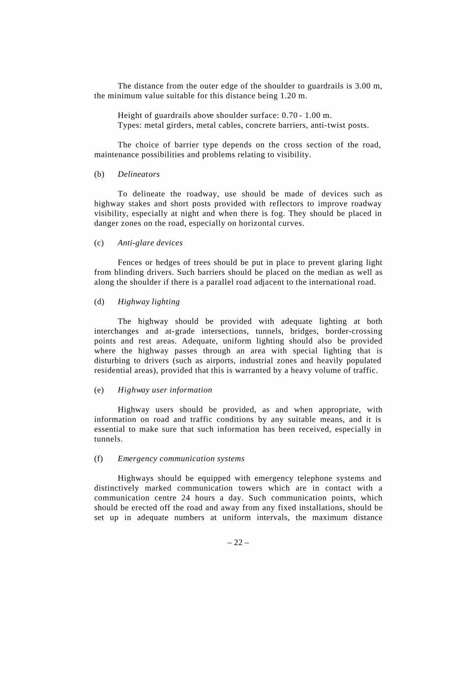
The distance from the outer edge of the shoulder to guardrails is 3.00 m, the minimum value suitable for this distance being 1.20 m. Height of guardrails above shoulder surface: 0.70 - 1.00 m. Types: metal girders, metal cables, concrete barriers, anti-twist posts. The choice of barrier type depends on the cross section of the road, maintenance possibilities and problems relating to visibility. (b) Delineators To delineate the roadway, use should be made of devices such as highway stakes and short posts provided with reflectors to improve roadway visibility, especially at night and when there is fog. They should be placed in danger zones on the road, especially on horizontal curves. (c) Anti-glare devices Fences or hedges of trees should be put in place to prevent glaring light from blinding drivers. Such barriers should be placed on the median as well as along the shoulder if there is a parallel road adjacent to the international road. (d) Highway lighting The highway should be provided with adequate lighting at both interchanges and at-grade intersections, tunnels, bridges, border-crossing points and rest areas. Adequate, uniform lighting should also be provided where the highway passes through an area with special lighting that is disturbing to drivers (such as airports, industrial zones and heavily populated residential areas), provided that this is warranted by a heavy volume of traffic. (e) Highway user information Highway users should be provided, as and when appropriate, with information on road and traffic conditions by any suitable means, and it is essential to make sure that such information has been received, especially in tunnels. (f) Emergency communication systems Highways should be equipped with emergency telephone systems and distinctively marked communication towers which are in contact with a communication centre 24 hours a day. Such communication points, which should be erected off the road and away from any fixed installations, should be set up in adequate numbers at uniform intervals, the maximum distance

– 23 –
between them being five kilometres. Signs should be erected indicating the direction of and distance to the nearest communication point. Where the erection of communication points is not feasible, recourse may be had to public telephones, in which case signs should be placed along the road indicating the location of the nearest public telephone. Clear instructions for using the telephone should be present in both Arabic and English. (g) Service facilities Service stations, vehicle repair shops and rest areas: at intervals no greater than 200 km. (h) Toll-booth areas It is essential to locate toll-booth areas in clear, open places and to avoid hazardous areas such as the lower part of vertical curves. Ample space must be set aside for toll-booth area facilities, such as control areas and residential areas for toll-station employees. (i) Border-crossing centres The design of border-crossing centres must take into account aspects relating to the types, number and distribution of vehicles passing through them as well as the transit traffic volume. Buildings must be erected for border-crossing operations, such as security procedures, customs, sanitary inspection and others. It is advantageous to establish, by agreement between the parties concerned, common border-crossing centres between two neighbouring members with a view to facilitating traffic flows and consequently increasing trade and tourism. It is important to equip border-crossing centres with adequate traffic signals to determine the movement of trucks and private cars, which should follow separate lanes. At border-crossing centres having a heavy volume of truck traffic, adequate facilities should be built to ensure the rapid completion of operations; moreover, if there are truck weighing stations, a place should be set aside for them that does not impede the flow of traffic at the border-crossing centre. (j) Auxiliary facilities (1) Pedestrian safety In the extremely limited number of places where the crossing of
pedestrians is permitted, special bridges or tunnels must be built for such crossing.

– 24 –
(2) Protection of the disabled It is essential to provide facilities for the travel of disabled
persons, and it is therefore essential to provide special means to facilitate their movements, especially at rest areas, as well as other services in keeping with their special needs.
(3) Protection of animals Protective fences must be provided along both sides of the
highway in places where animals are likely to cross. Inasmuch as such animals must be kept away from the roadway, special places must be provided for them to cross.
5. Vehicle characteristics
(a) Axle loads (1) Standard axle load as a basis of structural design for pavements, bridges and footbridges Depends on the design method followed in each member. (2) Axle loads As indicated in table 1.
6. Environmental considerations The region’s international road network is not for regional use alone: to a large extent it will serve international traffic and transit to the region. For this reason it must provide means of environmental protection and the greatest possible preservation of adjacent natural areas (rivers, trees, etc.). Furthermore, increased traffic on portions of the network passing in the vicinity of residential areas may require the construction of noise barriers.
7. Maintenance (a) General considerations The Arab Mashreq road network and all related facilities must be maintained in like-new condition to ensure the safety and comfort of highway users. Clearly defined programmes must be set up for the maintenance of any road in the network so as to avoid traffic delays due to failures occurring in it. It is important for the maintenance programmes set up to cover all aspects of

– 25 –
the road, including asphalt surfaces, concrete and steel structures, cut and fill areas, water drainage areas, traffic signals and signs of all types, as well as tree growth, etc., so as to prevent plant growth from reducing sight distance. In addition, special maintenance equipment must be made available, such as equipment for snow removal and for clearing stream beds, so that the absence of such equipment will not constitute a hindrance to the flow of traffic. On all parts of the network it is essential to distinguish between preventive maintenance and routine maintenance, so as to be able to institute the most efficient maintenance programme possible. (b) Maintenance management systems The maintenance management system on all parts of the Arab Mashreq road network requires specialized programmes. Such maintenance programmes should be entrusted to competent highway authorities, who will play the primary role in collecting and analysing data and taking decisions relating to maintenance. The authorities concerned in each member should be in possession of detailed information relating to roads in order to be able to help expedite the performance of maintenance operations in the event of accidents so that they do not result in any hindrance to the flow of traffic. Budget allocations should be made for maintenance operations and their priorities should be defined on the basis of the results of field measurements and observations to facilitate visibility both night and day and also in the light of recognized international requirements. It is imperative that the authorities concerned with the implementation of planning policies and maintenance should take into account all the related aspects, such as installing traffic signals, defining vehicle speeds and ensuring the proper performance of maintenance work in accordance with the programmes established for that purpose. (c) Special maintenance issues Special care should be given to maintenance work having a bearing on traffic safety. Such work includes the following:
(1) Pavement work for providing an anti-skid surface and also water-drainage works;
(2) Concrete structures, and in particular expansion joints, supports
and railings, whether on bridges or tunnel structures;

– 26 –
(3) Lighting and traffic safety means; (4) Road signs and pavement markings; (5) Works connected with the removal of all materials that might
cause traffic accidents, such as snow, sand, etc . It is imperative to make sure of the quality of the international road network by implementing a maintenance policy that guarantees continuity of service during maintenance work; moreover, such work should be performed at suitable times, so as to avoid excessive deterioration of the pavement. The safety of road maintenance crews must be ensured. This means taking adequate measures, to be adopted during the planning of the maintenance work and continuously adhered to throughout its actual performance. Highway safety devices, such as traffic signs and signals, must be fully available so as to prevent traffic accidents and the hampering of the flow of vehicle traffic. Such devices must be clearly visible both day and night. Periodic inspections should be conducted to make sure that they are clear and are providing their intended messages and that they are in accord with the international practices that govern such matters. The continuity of the flow of traffic under adverse weather conditions over the entire international road network must be ensured to the utmost degree. Care must be taken to remove snow and ice, earth or sand from the roadway and all traffic signs and signals, which constitutes additional maintenance work to be performed during certain seasons.
C. ANNEX III: STANDARD ROAD SIGNS , TRAFFIC SIGNALS AND PAVEMENT MARKINGS
ON THE ROUTES OF THE ARAB MASHREQ INTERNATIONAL ROAD NETWORK
1. General remarks
(a) The signatories to the Agreement undertake to design and produce traffic signs and signals and pavement markings in accordance with the Convention on Road Signs and Signals of 8 November 1968 (the Vienna Convention), prepared by the United Nations, as amended; (b) The specifications contained in the Vienna Convention concerning the shape of signs for which more than one option is proposed with regard to

– 27 –
geometric shape and color are defined in section 2 of this annex, entitled “Sign shapes”; (c) The dimensions of signs are defined in section 3 of this annex, entitled “Sign dimensions”; (d) The specifications regarding the writing on signs are defined in section 4 of this annex, entitled “The writing on road signs”; (e) The road number signs characteristic of the roads of the Arab Mashreq should be as described in section 5 of this annex, entitled “Road number sign”.
2. Sign shapes (a) Warning signs (Vienna Convention, annex 1, section A, Danger warning signs, paragraph 1): Definition: The sign shape is in accordance with model (Aa), which is
an equilateral triangle having its base horizontal and the opposite vertex above it; the ground is reflective white and the border reflective red, while the figures, forms and symbols are dark black.
(b) Informative signs (Vienna Convention, annex 1, section F, Information, facilities or service signs, paragraph 1): Definition: Signs indicating services and useful information shall be in
the shape of a rectangle having a blue ground, with writing in white, or in accordance with the Vienna Convention.
(Vienna Convention, annex 1, section G, Direction, position or indication signs, paragraph 3): Definition: Advance direction signs and direction signs shall be
rectangular, having writing and symbols displayed in white on a blue ground with a white border, or in accordance with the Vienna Convention.

– 28 –
(c) Regulatory signs (1) “STOP” sign (Vienna Convention, annex 1, section B, Priority signs): Definition: The model used is B, 2a; the “STOP” sign shall have a red
ground with a white border, the word “STOP” being written in white in both Arabic and English.
(2) “GIVE WAY” sign (Vienna Convention, annex 1, section B, Priority signs): Definition: The “GIVE WAY” sign shall consist of an equilateral
triangle having one side horizontal and the opposite vertex below it. The ground shall be white and the border red.
(3) “END OF PROHIBITION OR RESTRICTION” sign (Vienna Convention, annex 1, section C, Prohibitory or restrictive signs, subsection II. 8): Definition: Circular with a white ground, without a border, bearing a
group of bl ack or dark grey parallel lines sloping downward from right to left.
(4) “PRIORITY FOR ONCOMING TRAFFIC” sign (Vienna Convention, annex 1, section B, Priority signs): Definition: Circular, with a white ground and a red border. The arrow
pointing upward shall be red and the other arrow white. (5) Mandatory signs (Vienna Convention, annex 1, section D, Mandatory signs, paragraph 2): Definition: Mandatory signs shall be circular, without a border, with a
blue ground and white symbols, or in accordance with the Vienna Convention.

– 29 –
3. Sign dimensions Signs shall be in three sizes: small (600-750 mm), regular (900 mm) and large (1200-1500 mm), the size being determined by the maximum speed on the highway, as can be seen from table 2.
TABLE 2. TRAFFIC SIGN DIMENSIONS
Maximum speed (km/hour) Nature of sign Shape 60-75 > 75-90 > 90 Warning
Equilateral triangle Side length (mm)
600-750 900 1200-1500
STOP
Equilateral octagon Diameter (mm)
600-750 900 1200-1500
GIVE WAY
Equilateral triangle Side length (mm)
600-750 900 1200-1500
Priority Road
Square Length of side (mm)
600-750 600-750 600-750
Priority over oncoming traffic
Square Length of side (mm)
600-750 600-750 600-750
Other regulatory Circle Diameter (mm)
600-750 900 1200-1500
4. The writing on road signs Writing on signs shall be in both Arabic and English, the height of the Arabic letter “alif” being at least 1.5 times the height of the lower-case English letter.
Writing in Arabic shall be in the naskhi script; writing in English shall be in Roman type.
The space between lines should be equal to the letter height.
As for letter size, signs should be designed to be easy to read and to enable the driver to respond quickly at the appropriate time, which means that the characters should be adequately large for the speed of traffic on the road.
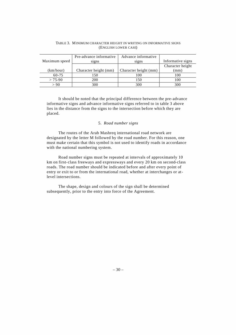
Character height on informative signs depends on the maximum permissible speed on the highway, as shown in table 3.
– 30 –
TABLE 3. M INIMUM CHARACTER HEIGHT IN WRITING ON INFORMATIVE SIGNS (ENGLISH LOWER CASE)
Maximum speed Pre-advance informative
signs Advance informative
signs Informative signs
(km/hour) Character height (mm) Character height (mm) Character height
(mm) 60-75 150 100 100 > 75-90 200 150 100
> 90 300 300 300
It should be noted that the principal difference between the pre-advance informative signs and advance informative signs referred to in table 3 above lies in the distance from the signs to the intersection before which they are placed.
5. Road number signs The routes of the Arab Mashreq international road network are designated by the letter M followed by the road number. For this reason, one must make certain that this symbol is not used to identify roads in accordance with the national numbering system. Road number signs must be repeated at intervals of approximately 10 km on first-class freeways and expressways and every 20 km on second-class roads. The road number should be indicated before and after every point of entry or exit to or from the international road, whether at interchanges or at-level intersections. The shape, design and colours of the sign shall be determined subsequently, prior to the entry into force of the Agreement.