agrément certificate 93/2914 · originally certificated on 10 june 1993 head of approvals ... †...
TRANSCRIPT

Page 1 of 16
TECHNICAL APPROVALS FOR CONSTRUCTION
APPROVAL
INSPECTION
TESTING
CERTIFICATION
Alumasc Exterior Building Products LimitedWhite House WorksBold RoadSuttonSt HelensMerseyside WA9 4JGTel: 01744 648400 Fax: 01744 648401e-mail: [email protected]: www.alumascfacades.co.uk
British Board of Agrément tel: 01923 665300Bucknalls Lane fax: 01923 665301Garston, Watford e-mail: [email protected] WD25 9BA website: www.bbacerts.co.uk©2010
The BBA is a UKAS accredited certification body — Number 113. The schedule of the current scope of accreditation for product certification is available in pdf format via the UKAS link on the BBA website at www.bbacerts.co.uk
Readers are advised to check the validity and latest issue number of this Agrément Certificate by either referring to the BBA website or contacting the BBA direct.
SWISSLAB EXTERNAL WALL INSULATION SYSTEMS
SWISSLAB MINERAL WOOL, SPAR-DASH RENDER FINISH, EXTERNAL WALL INSULATION SYSTEM
PRODUCT SCOPE AND SUMMARY OF CERTIFICATE
This Certificate relates to Swisslab Mineral Wool, Spar-dash Render Finish, External Wall Insulation System, employing mineral wool insulation slabs, glassfibre reinforcing mesh or lath, and spardash render finish, which is applied to the outside of external walls of masonry, dense or no-fines concrete construction and are suitable for new or existing buildings.
AGRÉMENT CERTIFICATION INCLUDES:• factors relating to compliance with Building
Regulations where applicable• factors relating to additional non-regulatory
information where applicable• independently verified technical specification• assessment criteria and technical investigations• design considerations• installation guidance• regular surveillance of production• formal three-yearly review.
KEY FACTORS ASSESSEDStrength and stability — the system can adequately resist wind loads and, in certain applications, impact damage (see section 5).Properties in relation to fire — the system has an external surface spread of flame of Class 0. Fire barriers may not be required at each floor level above the first floor (see section 6).Condensation — the system can contribute to limiting the risk of interstitial and surface condensation (see section 9).Thermal performance — the systems can be used to improve the thermal performance of external walls (see section 10).Durability — with appropriate care, the system should remain effective for at least 30 years (see section 12).
Agrément Certificate93/2914
Product Sheet 4
The BBA has awarded this Agrément Certificate to the company named above for the systems described herein. These systems have been assessed by the BBA as being fit for their intended use provided they are installed, used and maintained as set out in this Certificate.
On behalf of the British Board of Agrément
Date of First issue: 28 June 2010 Brian Chamberlain Greg CooperOriginally certificated on 10 June 1993 Head of Approvals — Engineering Chief ExecutiveCertificate amended on 10 November 2010 to include clarification of the comment to Standard 2.7 (page 2).

Page 2 of 16
In the opinion of the BBA, the Swisslab Mineral Wool, Spar-dash Render Finish, External Wall Insulation System, if used in accordance with the provisions of this Certificate, will meet or contribute to meeting the relevant requirements of the following Building Regulations:
The Building Regulations 2000 (as amended) (England and Wales)
Requirement: A1 Loading
Comment: The system can sustain and transmit wind loads to the substrate wall. See sections 3.4 and 5.1 to 5.6 of this Certificate.
Requirement: B4(1) External fire spread
Comment: The system is classified Class 0 and, therefore, can meet this Requirement. See sections 6.2 to 6.5 of this Certificate.
Requirement: C2(b) Resistance to moisture
Comment: The system provides a degree of protection against rain ingress. See sections 8.1 and 8.2 of this Certificate.Requirement: C2(c) Resistance to moisture
Comment: The system contributes to minimising the risk of interstitial and surface condensation. See sections 9.1 and 9.3 of this Certificate.
Requirement: L1(a)(i) Conservation of fuel and power
Comment: The system can contribute to enabling a wall to meet the Target Emission Rate. See sections 10.3 to 10.6 of this Certificate.
Requirement: Regulation 7 Materials and workmanship
Comment: The system is acceptable. See section 12.1 and the Installation part of this Certificate.
The Building (Scotland) Regulations 2004 (as amended)
Regulation: 8(1)(2) Fitness and durability of materials and workmanship
Comment: The system can contribute to a construction meeting this Regulation. See sections 11.1 and 12.1 and the Installation part of this Certificate.
Regulation: 9 Building standards — constructionStandard: 1.1 Structure
Comment: The system can sustain and transmit wind loads to the substrate wall. See sections 3.4 and 5.1 to 5.6 of this Certificate.
Standard: 2.6 Spread to neighbouring buildings
Comment: The system incorporates materials which would not be classed as ‘non-combustible’. Completed walls, therefore, should be regarded as unprotected areas as defined in this Standard, with reference to clauses 2.6.1(1)(2) and 2.6.2(1)(2). See sections 6.2 to 6.4 of this Certificate.
Standard: 2.7 Spread on external walls
Comment: The system incorporates materials which would not be classed as ‘non-combustible’ as defined in this Standard, with reference to clauses 2.7.1(1)(2) and 2.7.2(2). See sections 6.3 to 6.4 of this Certificate.
Standard: 3.10 Precipitation
Comment: Walls insulated with the system will contribute to a construction satisfying this Standard, with reference to clause 3.10.1(1)(2). See sections 8.1 and 8.2 of this Certificate.
Standard: 3.15 Condensation
Comment: Walls insulated with the system will satisfy the requirements of this Standard, with reference to clauses 3.15.1(1), 3.15.4(1) and 3.15.5(1). See sections 3.6, 9.2 and 9.3 of this Certificate.
Standard: 6.1(a)(b) Carbon dioxide emissionsStandard: 6.2 Buildings insulation envelope
Comment: The system can contribute to satisfying this Standard, with reference to clauses (or parts of) 6.1.1(1), 6.1.3(2), 6.1.5(2), 6.1.6(1), 6.2.1(1), 6.2.3(1), 6.2.4(1), 6.2.5(1)(2) and 6.2.10(2). See sections 10.3 to 10.6 of this Certificate.
(1) Technical Handbook (Domestic). (2) Technical Handbook (Non-Domestic).
The Building Regulations (Northern Ireland) 2000 (as amended)
Regulation: B2 Fitness of materials and workmanship
Comment: The system is acceptable. See section 12.1 and the Installation part of this Certificate.Regulation: B3(2) Suitability of certain materials
Comment: The system is acceptable. See section 11.1 of this Certificate.Regulation: C4(b) Resistance to ground moisture and weather
Comment: Walls insulated with the system will satisfy this Regulation. See sections 8.1 and 8.2 of this Certificate.Regulation: C5 Condensation
Comment: Walls insulated with the system will satisfy the requirements of this Regulation. See sections 3.6, 9.1 and 9.3 of this Certificate.
Regulation: D1 Stability
Comment: The system can sustain and transmit wind loads to the substrate wall. See sections 3.4, 5.1 to 5.6 of this Certificate.
Regulations

Page 3 of 16
Regulation: E5 External fire spread
Comment: The system has a Class 0 surface and can satisfy this Regulation. See sections 6.2 to 6.4 of this Certificate.Regulation: F2(a)(i) Conservation measures
Comment: The system will enable a wall to meet the requirements of this Regulation. See sections 10.3 to 10.6 of this Certificate.
Regulation: F3 Target carbon dioxide Emission Rate
Comment: The system will contribute to a building satisfying its target emission rate. See sections 10.3 to 10.6 of this Certificate.
Construction (Design and Management) Regulations 2007Construction (Design and Management) Regulations (Northern Ireland) 2007
Information in this Certificate may assist the client, CDM co-ordinator, designer and contractors to address their obligations under these Regulations.See section: 2 Delivery and site handling (2.2 and 2.4) of this Certificate.
Non-regulatory Information
NHBC Standards 2008NHBC accepts the use of the Swisslab Mineral Wool, Spar-dash Render Finish, External Wall Insulation System, when installed and used in accordance with this Certificate, in relation to NHBC Standards, Chapter 6.9 Curtain walling and cladding.
General
This Certificate relates to the Swisslab Mineral Wool, Spar-dash Render Finish, External Wall Insulation System, comprising insulation board with reinforced undercoat and decorative finishes.
The system is applied to the outside of external walls of masonry and dense or no-fines concrete construction and is suitable for use on new or existing buildings.
Application and maintenance must be carried out strictly in accordance with this Certificate and the Certificate holder’s instructions, by installers trained and approved by the Certificate holder.
Technical Specification
1 Description1.1 The Swisslab Mineral Wool, Spar-dash Render Finish, External Wall Insulation System (see Figure 1) comprises mineral wool insulation slabs, mechanical fixings, adhesives, basecoat and finish coats. There are various fixing options available with the system. Details of the main components used, in the order of application to the substrate, are:• M.R. Bedding Adhesive — polymer-modified, cement-based adhesive, supplied as powder to which water is added• Swisslab mineral wool insulation — slab 1000 mm by 500 mm or 1200 mm by 600 mm in a range of thicknesses
between 20 mm and 200 mm in increments of 10 mm, with nominal densities of 100 kg·m–3 (crimped only), 128 kg·m–3, 140 kg·m–3 and 160 kg·m–3 with typical compression resistances (at 20% compression) of 35 Pa, 50 Pa, 65 Pa and 75 kPa respectively
• M.R. mechanical fixings — Termoz 8NZ, Termofix CF8, Termoz 8N, Termoz 8U, Termofix 6H (wooden substrates), Termofix B (steel frame), DIPK and DHM (stainless steel) supplied by the Certificate holder
• M.R. Scrim Adhesive — as M.R. Bedding Adhesive• Swisslab reinforcing mesh — a one-metre-wide mesh of multi-stranded alkali-resistant glassfibres, having a polymer
coating and a nominal weight of 150 g·m–2 or 200 g·m–2
• Spar dash finish: — M.R. S7 Dashing Render — a polymer-modified fibre-reinforced cement-based mortar supplied as a powder to
which water is added, and available coloured white, extra white, salmon, terracotta red, red, burgundy, gold, yellow, peach, grey, Scotland brown, light cream, cream, extra pink or pink. Other colours are available to order
— M.R. Spar-Dash Aggregate — available in a range of colours to suit the M.R. S7 Dashing Render.
1.2 With each installation, an Alumasc base profile to the specification described in section 1.3 and fixed to the substrate with Alumasc profile fixings, is used to align the boards (see Figure 1).

Page 4 of 16
Figure 1 Components
M.R. Bedding Adhesive
Swisslab mechanical fixing
Swisslab mineral wool insulation
existing substrate
Alumasc profile
M.R. S4 Plain Render orM.R. S7 Dashing Render
M.R. Scrim Adhesive
Swisslab reinforcing mesh beddedin M.R. Scrim Adhesive
1.3 Ancillary components, required during preparation and detailing, include:• M.R. S3 and M.R. S5 dubbing coat — a polymer-modified fibre-reinforced cement-based render, supplied as a
powder to which water is added• M.R. Fungicidal Wash• M.R. Stabilising Solution• Alumasc profiles — a range of standard profiles for use at details such as wall base, end stop, corner mesh and
expansion joint. Profiles are available in organic polyester-coated galvanized steel, stainless steel or PVC and are provided to the specifier’s requirements
• Alumasc profile fixings — driven pins with plastic expansion sleeves• M.R. Fir-Tree Fixings• Alumasc sealant — low-modulus silicone mastic provided to the specifier’s requirements• Ground floor edge insulation system.
1.4 All components are subject to routine factory quality controls.
Fixing methods and patterns1.5 There are two methods of fixing the insulation boards:
• dry-fix — insulation boards are mechanically fastened to the substrate• wet-fix — where the substrate surface has a levelling coat applied (see section 15.8) or in high-rise applications, the
insulation boards should be bonded to the wall with M.R. Bedding Adhesive and secured with mechanical fixings
1.6 There are two choices of fixing pattern (see Figure 2). For installations above two storeys, additional stainless steel fixings are applied through the reinforcing mesh and insulation boards and into the background at approximately one-metre centres.

Page 5 of 16
Figure 2 Insulation boards fixing pattern
stage 1 stage 2
additional fixings: one stainless steel fixing per square metre required above two storeys
standard fixings
fixings around openings at 300 mm centres maximum
additional reinforcing mesh 500 mm × 250 mm minimum
2 Delivery and site handling2.1 The insulation is delivered to site shrink-wrapped in polythene packs bearing the manufacturer’s and product’s identification marks and batch numbers.
2.2 Components are delivered to site in the quantities and packages as listed in Table 1. Each package carries the manufacturer’s and product’s identification, batch number, and the BBA logo incorporating the number of this Certificate.
Table 1 Component supply details
Component Quantity and package
M.R. S3 and M.R. S5F Dubbing Renders 25 kg
M.R. Bedding and Scrim Adhesives 25 kg
M.R. S Renders and Dubbing 25 kg
M.R. Spar-Dash Aggregate 25 kg
M.R. Mechanical Fixings boxed by manufacturer
M.R. Stabilising Solution 5 litre drum
M.R. Fungicidal Wash 5 litre drum
M.R. Fir-Tree Fixing boxed by manufacturer
Swisslab reinforcing mesh 50 m roll, 1 m wide
2.3 The insulation boards should be stored on a firm, clean, level base, off the ground and must be protected from prolonged exposure to rain by storing in a safe area under cover until required use.
2.4 Care must be taken when handling the insulation boards to avoid both damage and contact with solvents or bitumen products. Opened packs must be protected from the weather.
2 5 The decorative M.R. Spar-Dash Aggregate should be stored off the ground and protected with opaque polythene sheeting.
2.6 The M.R. polymer cement adhesives are cementitious materials and must be stored in dry conditions, off the ground, and protected from frost at all times.

Page 6 of 16
Assessment and Technical Investigations
The following is a summary of the assessment and technical investigations carried out on the Swisslab Mineral Wool, Spar-Dash Render Finish External Wall Insulation System.
Design Considerations
3 General3.1 Swisslab Mineral Wool, Spar-Dash Render Finish, External Wall Insulation System, when installed in accordance with this Certificate, is effective in reducing the thermal transmittance (U value) of the walls of new and existing buildings. It is essential that the detailing techniques specified in this Certificate are carried out to a high standard, if the ingress of water into the insulation is to be avoided and the full thermal benefit obtained from treatment with the system.
3.2 The system will improve the weather resistance of a wall and provide a decorative finish. However, they may be installed only where other routes for moisture penetration have been dealt with separately and where there are no signs of dampness on the inner surface of the wall, other than those caused solely by condensation. The system can be used to overcome condensation associated with the internal wall surface.
3.3 Existing buildings subject to national Building Regulations should have wall surfaces in accordance with section 14 Site survey and preliminary work in the Installation of this Certificate.
3.4 New buildings subject to national Building Regulations should be constructed in accordance with the relevant recommendations of:
• BS EN 1996-2 : 2006 should be followed in that the designer should select a construction appropriate to the local wind-driven rain index, paying due regard to the design detailing, workmanship and materials to be used
• BS 8000-3 : 2001.
3.5 Other new buildings, not subject to any of the previous requirements, should also be built in accordance with BS EN 1996-2 : 2006.
3.6 When using the system, consideration must be given to the overall design to minimise the risk of condensation and the recommendations of BS 5250 : 2002 should be followed.
4 Practicability of installationThe systems should only be installed by installers who have been trained and approved by the Certificate holder (see section 13).
5 Strength and stability5.1 When installed on suitable walls, the systems can adequately transfer self-weight, and negative and positive (suction and pressure) wind loads normally experienced in the United Kingdom, to the wall.
5.2 The ultimate wind load to be resisted by the system should be determined by calculating the wind load in accordance with BS EN 1991-1-4 : 2005 and multiplying by a load factor of 1.5 (as recommended in BS EN 1990 : 2002). Special consideration should be given to locations with high wind-load pressure coefficients (additional fixings or adhesive may be necessary).
5.3 Assessment of structural performance for individual installations should be carried out by a suitably qualified engineer or other appropriately qualified person to confirm that:• the substrate wall has adequate strength to resist the additional loads that may be applied as a result of installing the
system ignoring any positive contribution that may occur from the system• the proposed system and associated fixing layout provides adequate resistance to negative wind loads.
5.4 For a system using M.R. standard fixings with 50 mm diameter heads, the dry-fix system (see Figure 2) can withstand wind loads up to 2.5 kPa when installed in accordance with the manufacturer’s instructions and the Installation part of this Certificate. The same dry-fix system using M.R. fixings with 90 mm diameter heads can withstand wind loads up to 3.5 kPa; with M.R. standard fixings with 50 mm diameter heads arranged in fixing pattern (see Figure 2), it can withstand wind loads up to 2.0 kPa.
5.5 For the dry-fix system with 50 mm or 90 mm diameter fixing heads, the wind suction forces to be resisted on any particular site calculated in accordance with BS EN 1991-1-4 : 2005, including any required safety factor, would be less than 2.5 kPa and 3.5 kPa, respectively.
Impact resistance5.6 The systems have adequate resistance to impact and abrasion where walls are exposed and have some protection, eg walls of private dwellings and walls of communal dwellings above ground-floor level. Where a system may be exposed to severe mechanical or malicious impact, eg walls of public buildings at ground-floor level,

Page 7 of 16
precautions (such as supplementary reinforcement) may be required to reduce the risk of damage. Guidance may be obtained from the Certificate holder or BS 8200 : 1985.
6 Properties in relation to fire6.1 In the opinion of the BBA, the use of the system will not introduce any additional hazard in respect of behaviour in fire when compared with a system using traditional sand/cement render finishes.
6.2 Each system is classified Class 0 or ‘low risk’ as defined in the national Building Regulations.
6.3 Any cavities within the system (such as those formed between the external wall insulation system and the substrate) must have appropriate fire stopping in accordance with national Building Regulations.
6.4 The behaviour in fire of external wall insulation systems is the subject of recommendations given in BRE report (BR 135 : 2003, Second edition) Fire Performance of External Insulation For Walls of Multi-Storey Buildings including guidance on the design of fire barriers for use in this type of system. The height of the building is not restricted when using this system.
7 Proximity of flues and appliancesFor this external wall insulating system there are no provisions to be met.
8 Rain penetration8.1 The system will provide a degree of protection against rain ingress. However, care should be taken to ensure that walls are adequately weathertight prior to its application.
8.2 Designers and installers should take particular care in detailing around openings, penetrations and movement joints to minimise the risk of rain ingress.
9 CondensationSurface condensation
9.1 Walls will limit the risk of surface condensation adequately when the thermal transmittance (U value) does not exceed 0.7 W·m–2·K–1 at any point and the junctions with other elements and openings comply with section 10.5.
9.2 Walls will adequately limit the risk of surface condensation when the thermal transmittance (U value) does not exceed 1.2 W·m–2·K–1 at any point. Guidance may be obtained from BS 5250 : 2002, Section 8, and BRE report (BR 262 : 2002).
Interstitial condensation9.3 Walls incorporating the systems will adequately limit the risk of interstitial condensation when they are designed and constructed in accordance with BS 5250 : 2002, Section 8 and Annex D.
10 Thermal performance10.1 Calculations of thermal transmittance (U value) should be carried out in accordance with BS EN ISO 6946 : 2007 and BRE report (BR 443 : 2006) Conventions for U-value calculations, using the insulation’s declared thermal conductivity (λ90/90) in Table 2.
Table 2 Thermal conductivity values
Insulation λ value (W·m–1·K–1)
Mineral wool 0.036
10.2 The U value of a completed wall will depend on the selected insulation thickness, the insulating value of the substrate and its internal finish. Calculated U values for example constructions are given in Table 3. The calculations are based on insulation boards fixing patterns A and B as shown in Figure 2.

Page 8 of 16
Table 3 Example wall U values — Dense concrete block and brickwork (1)
U value (W·m–2·K–1)
Mineral wool insulation thickness(2) (mm)
20 40 60 80 100 120 140 160 180 200
Dense concrete block 1.16 0.71 0.51 0.40 0.32 0.27 0.24 0.21 0.19 0.17
Brickwork 0.88 0.59 0.44 0.36 0.30 0.26 0.22 0.20 0.18 0.16
(1) 200 mm thick dense concrete block (λ = 1.75 W·m–1·K–1) and 220 mm brickwork (λ = 0.56 W·m–1·K–1). Glassfibre-reinforced plastic nails — Corrections for fixing less than 3% of U value. Corrections for other types of fixings should be calculated in accordance with BS EN ISO 6946 : 2007, Annex D.
(2) Boards supplied in thicknesses from 20 mm to 300 mm in increments of 10 mm.
10.3 When considering insulation requirements, designers should refer to the detailed guidance contained in the documents supporting the national Building Regulations. The U values shown in Tables 4 and 5 indicate that the product can enable a wall to achieve the typical design U values referred to in those supporting documents
(see Tables 4 and 5).
New buildings10.4 Walls with U values lower than (or the same as, for dwellings in Scotland) the relevant ‘notional’ value specified in Table 4 or 5 will contribute to a building meeting its Target Emission Rate. Walls with higher U values will require additional energy saving measures in the building envelope and/or services.
10.5 The system can maintain, or contribute to maintaining, continuity of thermal insulation around openings and at junctions between external walls and other building elements. Details shown in Figures 3, 6, 7, 8 and 9 will allow use of the default psi values for Accredited Construction details in Emission Rate calculations to
SAP 2005 or the Simplified Building Energy Model (SBEM). Detailed guidance in this respect and on limiting heat loss by air infiltration can be found in:England and Wales — Limiting thermal bridging and air leakage: Robust construction details for dwellings and similar buildings TSO 2002 or Accredited Construction Details (version 1.0)Scotland — Accredited Construction Details (Scotland)Northern Ireland — Accredited Construction Details (version 1.0).
Existing buildings10.6 For existing buildings, extensions and conversions, walls will be acceptable where they do not exceed the relevant U value in Table 4 or 5 and junctions and openings comply with section 10.5 or BR report (BR 262 : 2002) Thermal insulation: avoiding risks.
Table 4 Typical design U values for walls — England and Wales and Northern Ireland
U value (W·m–2·K–1) Construction type
0.30 Mean for new extensions(1)
0.35 ‘Notional’ mean in SAP and SBEM and limit mean for new-build
0.35 Mean for replacement, renovated, and retained walls and non-domestic consequential improvements(1)
0.70 Individual limit for new-build and flexible approaches(1)
(1) Alternative/flexible approaches are given in the relevant documents supporting the national Building Regulations.
Table 5 Typical design U values for walls — Scotland
U value (W·m–2·K–1) Construction type
0.200.25
‘Notional’ mean for dwellings in SAP and the ‘simplified’ approach:— solid fuel, package 6— other fuels, packages 1–5
0.27 Mean for new extensions, conversions and alterations(1)
0.27 Mean for stand-alone buildings less than 50 m2
0.30 ‘Notional’ mean for non-domestic in SBEM and limit mean for new-build
0.70 Individual limit for new-build, extensions, conversions, alterations and stand-alone buildings less than 50 m2
(1) Alternative/flexible approaches are given in the relevant documents supporting the national Building Regulations.
11 Maintenance11.1 Regular checks should be made on the installed system, particularly at joints, to ensure that ingress of water does not occur. This includes checks on joints in the system and on any penetrations through the system (such as those caused by external plumbing fitments) to identify leakage of rainwater into the system, enabling
steps to be taken to correct the defects. Necessary repairs should be carried out immediately.

Page 9 of 16
11.2 Damaged areas must be repaired using the appropriate Swisslab components and the procedures detailed in the Swisslab installation instructions.
12 Durability12.1 The system should remain effective for at least 30 years, provided any damage to the surface finish is repaired immediately, and regular maintenance is undertaken. This includes checks on joints in the system and external plumbing fitments to prevent leakage of rainwater into the system (see section 11).
12.2 The decorative finishes may become discoloured with time, the rate depending on the initial colour, the degree of exposure, atmospheric pollution and the nature of the natural aggregate, as well as the design and detailing of the wall. In common with traditional renders, discoloration by algae and lichens may occur in particularly wet areas. The appearance can be restored by using traditional cleaning methods suitable for sand/cement renders (such as by brushing and washing).
12.3 Render containing Portland cement may be subject to lime bloom. The occurrence of this may be reduced by avoiding application in adverse weather conditions. The effect is transient and less noticeable on lighter colours.
Installation
13 Approved installersApplication of the system, within the context of this Certificate, is carried out by approved installers. An approved installer is a company:• employing operatives who have been trained and approved by the Certificate holder to install the system and who
have been issued with appropriate training cards by the Certificate holder• having undertaken to comply with the Certificate holder’s application procedure, which contains the requirement for
each application team to include at least one member with a training card, and• subject to supervision by the Certificate holder. This may include unannounced site inspections.
14 Site survey and preliminary work14.1 A pre-installation survey of the property is carried out to determine suitability for treatment and the need for any necessary repairs to the building structure before application of the Swisslab Mineral Wool, Spar-Dash Render Finish, External Wall Insulation System. A specification is prepared for each project indicating:• where required, additional corner mesh and reinforcement• the position of beads• detailing around windows, doors and at eaves• dpc level• exact position of expansion joints• areas where flexible sealants must be used• any alterations to external plumbing• where required, the position of fire barriers.
14.2 The survey should include tests conducted on the walls of the building by the Certificate holder or its approved suppliers to determine the pull-out resistance of the proposed mechanical fixings. An assessment and recommendation is made on the type and number of fixings required to withstand the building’s expected wind loading based on calculations using the site test data, the relevant wind speed data for the site and, in the absence of a formal requirement, the application of a safety factor of 3.
14.3 All necessary repairs to the building structure are completed before installation of the system is started.
14.4 Surfaces should be sound, clean, and free from loose material. The flatness of surfaces must be checked; this may be achieved using a straight-edge spanning the storey-height. Excessive irregularities, ie greater than 10 mm, must be made good using M.R. S3 or M.R. S5 Dubbing Render prior to installation to ensure that the insulation boards are installed with a smooth, in-plane finished surface.
14.5 Where surfaces are covered with an existing rendering, it is essential that the bond between the background and the render is adequate. All loose areas should be removed and made good using M.R. S3 or M.R. S5 Dubbing Render.
14.6 On existing buildings, purpose-made sills must be fitted to extend beyond the finished face of the system (see Figure 9). New buildings should incorporate suitably deep sills.
14.7 It is recommended that external plumbing be removed and alterations made to underground drainage, where appropriate, to accommodate repositioning on the finished face of the systems.
14.8 New buildings should be of sound masonry, dense or no-fines concrete construction.
14.9 Internal wet work, eg screeding or plastering, should be completed and allowed to dry prior to the application of a Swisslab system.

Page 10 of 16
14.10 Where possible, independent scaffolding should be used to avoid the need to subsequently make good putlog holes and other breaks in the wall. Where scaffolding is required to be tied back to the building, it is normal to recommend ‘box-outs’ to reduce the incidence of patches left by putlogs and to provide access points for future scaffolding that may be required for maintenance, inspection and repairs.
14.11 The scaffolding must be arranged to allow sufficient access to the whole face of the building. Sufficient clearance for working should be provided between the scaffolding and the finished surface of the system. An allowance should be included for the thickness of the finished system on the face of the building.
15 ProcedureGeneral15.1 Application is carried out in accordance with the Certificate holder’s current installation instructions.
15.2 M.R. Bedding Adhesive, Scrim Adhesive, Dubbing and render coats must not be applied in rain or mist, at temperatures below 5°C or above 30°C, if exposure to frost is likely to occur during drying, or if the boards or background are already wet or frostbound.
15.3 All rendering should be in accordance with the relevant recommendations of BS EN 13914-1 : 2005.
15.4 M.R. adhesives and renders are mixed using a paddle mixer. Conventional concrete mixers are unsuitable.
Positioning and securing insulation boards15.5 One coat of M.R. Fungicidal Wash followed, if required, by one coat of M.R. Stabilising Solution is applied by brush, roller or knapsack spray to the entire wall surface if wet fixing or areas that require dubbing render.
15.6 The Alumasc base profile is secured to the external wall above the damp-proof course using the approved profile fixings at approximately 300 mm centres (see Figure 3).
Figure 3 Typical section at base level
15.7 Stop beads are positioned vertically or ‘wrap back’ technique, eg at party wall positions where the adjoining house does not require treatment (see Figure 4).

Page 11 of 16
Figure 4 Typical end stop detail
15.8 To compensate for minor variations in the backing wall flatness, if required, M.R. Bedding Adhesive (wet-fix system) is prepared for use by mixing the contents of each 25 kg bag with 4.5 to 5 litres of cold, clean water. An electrically driven paddle mixer is used for a minimum of five minutes until a smooth,workable consistency is achieved. The material is left to stand for at least five minutes and again mixed for a further two minutes. The bed coat of M.R. Bedding Adhesive can be applied in one of three ways:• adhesive can be applied by trowel to the full area of the back of the insulation board and notched with a 10 mm
notch trowel and the board placed firmly against the substrate• adhesive can be applied directly to the substrate and notched• using a dot and dab method, the edges of the insulation board are coated with the specified adhesive and three
large dabs of adhesive applied at even spacings to the centre of the board (adhesive must cover at least 40% of the board). The board is placed firmly against the substrate.
15.9 The first run of insulation boards is positioned on the base profile. When using the wet-fix system, boards are pressed firmly into the adhesive. Subsequent rows of boards are positioned so that the board joints are staggered by at least 200 mm and overlapped at the building corners and in such a manner that board joints do not occur within 200 mm of the corners of openings (see Figures 2 and 7). If required, the boards may be arranged with the longer edge positioned vertically.
15.10 For both dry- and wet-fix systems, the insulation boards are mechanically fastened to the wall using either fixing pattern A or B (see Figure 2). Mechanical fixings are positioned 300 mm apart around door and window details and at 300 mm vertical centres at building corners. At corners, fixings should be positioned inwards by 75 mm (see Figure 7) plus the thickness of the insulation. Holes are drilled into the substrate to a minimum depth of 50 mm and the mechanical fixings are inserted and tapped firmly into place, securing the insulation board to the substrate.
15.11 Care must be taken to ensure that all board edges are butted tightly together, and alignment should be checked as work proceeds. Any high spots or irregularities should be removed by lightly planing with a rasp.
15.12 To fit around details such as doors and windows, insulation boards may be cut with a sharp knife or fine-tooth saw. If required, purpose-made window sills are fitted (see Figure 9). They are designed to prevent water ingress and incorporate drips to shed water clear of the system.
Movement joints and profiles15.13 Movement joints in the substrate must be continued through the system. The joint detail using purpose-made metal trims is illustrated in Figure 5.

Page 12 of 16
Figure 5 Vertical movement joint detail
existing substructure
M.R. mechanical fixing6 mm gap between boards
Alumasc expansion profile
M.R. Fir-Tree FixingSwisslab reinforcing mesh beddedin M.R. Scrim Adhesive
M.R. S4 Plain Render orM.R. S7 Dashing Render
Swisslab mineral wool insulation
M.R. Bedding Adhesive(if required)
75 mm 75 mm
15.14 Expansion bead locations are marked vertically at agreed positions. These beads are positioned at approximately 7 m centres along a building depending on the individual requirements of each job.
Reinforcing15.15 The M.R. Scrim Adhesive is prepared as described in section 15.8 and a bed coat is trowel-applied to the surface of dry insulation boards to a minimum thickness of 3 mm.
15.16 M.R. Reinforcing Mesh is bedded into the adhesive with 75 mm minimum laps at joints. Extra mesh (500 mm by 250 mm) is used around openings (see Figure 2). Additional fixings are then fixed through the wet scrim adhesive (see Figure 2) at 450 mm centres maximum.
15.17 For installations above two storeys, additional holes are drilled at one-metre centres through the M.R. Scrim Adhesive and M.R. stainless steel fixings are inserted through the mesh and tapped firmly home. The fixings are covered with M.R. Scrim Adhesive and square pieces of M.R. Reinforcing Mesh measuring not less than 150 mm by 150 mm.
Rendering and finishing15.18 Alumasc expansion beads are fixed at agreed positions. Alumasc angle beads are fixed to all building corners and to door and window heads and jambs. The beads are fixed using M.R. Fir-Tree Fixings at maximum 300 mm centres after the Scrim Adhesive has cured.
15.19 Prior to the render coat, a bead of Alumasc Low Modulus Silicone Mastic is gun-applied at window and door frames, overhanging eaves, gas and electric meter boxes, wall vents or where the render abuts any other building material or surface.
15.20 The drying period of any render will depend on weather conditions. However, each coat must be left to harden for as long as possible in good drying conditions but before application of the subsequent coat. The scrim adhesive must be allowed to harden and dry for at least one day.
15.21 To prevent the renders from drying too rapidly they should not be applied in direct sunlight. Continuous surfaces must be completed without a break.
15.22 After application, care must be taken to protect the renders from direct sunlight, drying winds, rain, mist and cold (less than 5°C on a falling thermometer) to prevent the drying time from being too rapid or excessively prolonged.
15.23 The scrim adhesive must be allowed to harden and dry for at least one day before application of the M.R. S7 Dashing Render.
15.24 M.R. S7 Dashing Render or M.R. S4 Plain Render is prepared using the same procedures as for the M.R. Bedding Adhesive (see section 15.8) by mixing the contents of each 25 kg bag with approximately 5 to 5.6 litres and 4 to 4.5 litres of water respectively. Care must be taken to ensure an even dispersion of the resin and fibre reinforcement.
15.25 One coat of M.R. S7 Dashing Render or M.R. S4 Plain Render is trowel-applied to a minimum thickness of 8 mm. For the M.R. S7 Dashing Render, a minimum of three bags of suitable spar-aggregate should be emptied into a clean wheelbarrow or tub and any excess water allowed to drain before being mixed thoroughly. While the M.R. S7 Dashing Render is still soft, the aggregate is thrown or sprayed onto the surface. On completion, the surface must be checked to ensure an even coverage of spar dash has been achieved. Where necessary, the aggregate should be lightly tamped to ensure that a good bond is achieved. With M.R. S4 Plain Render, it is finished smooth with a stainless steel trowel, sponged up and allowed to dry. Any contaminants, such as grease, dirt, chalking, must be removed prior to the application of further top coats or paints.
15.26 M.R. S6 smooth finish masonry paint is applied in two coats by brush or roller, allowing sufficient drying time between each coat. Drying times depend on weather conditions.
Page 13 of 16
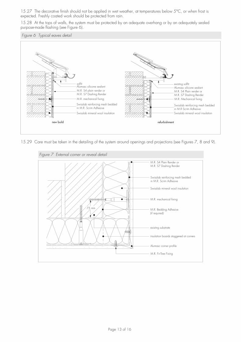
15.27 The decorative finish should not be applied in wet weather, at temperatures below 5°C, or when frost is expected. Freshly coated work should be protected from rain.
15.28 At the tops of walls, the system must be protected by an adequate overhang or by an adequately sealed purpose-made flashing (see Figure 6).
Figure 6 Typical eaves detail
soffit
Swisslab mineral wool insulation Swisslab mineral wool insulation
M.R. Mechanical fixingM.R. mechanical fixing
Swisslab reinforcing mesh beddedin M.R. Scrim Adhesive
M.R. S4 plain render orM.R. S7 Dashing Render
Alumasc silicone sealantexisting soffit
Swisslab reinforcing mesh beddedin M.R Scrim Adhesive
M.R. S4 Plain render orM.R. S7 Dashing Render
Alumasc silicone sealant
new build refurbishment
15.29 Care must be taken in the detailing of the system around openings and projections (see Figures 7, 8 and 9).
Figure 7 External corner or reveal detail
M.R. S4 Plain Render orM.R. S7 Dashing Render
Swisslab reinforcing mesh beddedin M.R. Scrim Adhesive
Swisslab mineral wool insulation
M.R. mechanical fixing
M.R. Bedding Adhesive(if required)
existing substrate
insulation boards staggered at corners
Alumasc corner profile
M.R. Fir-Tree Fixing
75 mm

Page 14 of 16
Figure 8 Insulated window or door reveal
existing window or door frame
Alumasc silicone sealant
Alumasc surface mounted stop profile
Alumasc corner profile
M.R. Fir-Tree Fixing
existing susbstructure
M.R. Bedding Adhesive
Swisslab mineral wool insulation
Swisslab reinforcing mesh beddedin M.R. Scrim Adhesive
M.R. S4 Plain Render orM.R. S7 Dashing Render
Figure 9 Typical sill detail
existing sill
M.R. Bedding Adhesive (if required)
Swisslab mineral wool insulation
M.R. mechanical fixing
Swisslab reinforcing mesh beddedin M.R. Scrim Adhesive
existing substrate
M.R. S4 Plain Render orM.R. S7 Dashing Render
Alumasc aluminium oversill
Alumasc specified fixing
15.30 On completion of the installation, external fittings, eg rainwater goods, are re-fixed through the system into the substrate.
15.31 For all rendering and application of finishing coats, continuous surfaces should be completed without a break.

Page 15 of 16
Technical Investigations
16 Tests 16.1 Tests were carried out in accordance with MOAT No 22 : 1988 to determine:• component characterisation• resistance to freeze/thaw• heat/spray cycling• impact resistance• water absorption of render• water vapour permeability.
16.2 An examination was made of data relating to:• resistance of dynamic wind uplift (1)
• flexural and compressive strength of renders• fire propagation tests to BS 476-6 : 1989• surface spread of flame tests to BS 476-7 : 1997• pull-out strength of fixings• durability of finish• thermal conductivity to BS EN ISO 6946 : 2007• bond strength of M.R. S3, M.R. S5 and M.R. S7.(1) Tests were conducted by the BBA generally in accordance with European Organisation for Technical Approvals’ draft ETAG Guidelines for
External Thermal Insulation Composite Systems with rendering.
17 Investigations17.1 An examination was made of the manufacturing process, the methods adopted for quality control of manufactured and bought-in components, and details of the quality and composition of the materials used.
17.2 A computer simulation of the risk of interstitial condensation was undertaken.
17.3 The practicability of installation and the effectiveness of detailing techniques were examined.
Bibliography
BS 476-6 : 1989 Fire tests on building materials and structures — Method of test for fire propagation for productsBS 476-7 : 1997 Fire tests on building materials and structures — Method of test to determine the classification of the surface spread of flame of products
BS 3837-1 : 2004 Expanded polystyrene boards — Boards and blocks manufactured from expandable beads — Requirements and test methods
BS 5250 : 2002 Code of practice for control of condensation in buildings
BS 8000-3 : 2001 Workmanship on building sites — Code of practice for masonry
BS 8200 : 1985 Code of practice for design of non-loadbearing external vertical enclosures of buildings
BS EN 1990 : 2002 Eurocode — Basis of structural design
BS EN 1991-1-4 : 2005 Eurocode 1 : Actions on structures — General actions — Wind actions
BS EN 1996-2 : 2006 Eurocode 6 : Design of masonry structures — Design considerations, selection of materials and execution of masonry
BS EN 13914-1 : 2005 Design, preparation and application of external rendering and internal plastering — External rendering
BS EN ISO 6946 : 2007 Building components and building elements — Thermal resistance and thermal transmittance — Calculation method
BS EN ISO 9001 : 2008 Quality management systems — Requirements
MOAT No 22 : 1988 UEAtc Directives for the Assessment of External Insulation Systems for Walls (Expanded Polystyrene Insulation Faced with a Thin Rendering)

Page 16 of 16
Conditions of Certification
18 Conditions18.1 This Certificate:• relates only to the product/system that is named and described on the front page• is granted only to the company, firm or person named on the front page — no other company, firm or person may
hold or claim any entitlement to this Certificate• is valid only within the UK• has to be read, considered and used as a whole document — it may be misleading and will be incomplete to be
selective• is copyright of the BBA• is subject to English law.
18.2 Publications and documents referred to in this Certificate are those that the BBA deems to be relevant at the date of issue or re-issue of this Certificate and include any: Act of Parliament; Statutory Instrument; Directive; Regulation; British, European or International Standard; Code of Practice; manufacturers’ instructions; or any other publication or document similar or related to the aforementioned.
18.3 This Certificate will remain valid for an unlimited period provided that the product/system and the manufacture and/or fabrication including all related and relevant processes thereof:• are maintained at or above the levels which have been assessed and found to be satisfactory by the BBA• continue to be checked as and when deemed appropriate by the BBA under arrangements that it will determine• are reviewed by the BBA as and when it considers appropriate.
18.4 In granting this Certificate, the BBA is not responsible for:• the presence or absence of any patent, intellectual property or similar rights subsisting in the product/system or any
other product/system• the right of the Certificate holder to manufacture, supply, install, maintain or market the product/system• individual installations of the product/system, including the nature, design, methods and workmanship of or related
to the installation• the actual works in which the product/system is installed, used and maintained, including the nature, design,
methods and workmanship of such works.
18.5 Any information relating to the manufacture, supply, installation, use and maintenance of this product/system which is contained or referred to in this Certificate is the minimum required to be met when the product/system is manufactured, supplied, installed, used and maintained. It does not purport in any way to restate the requirements of the Health & Safety at Work etc Act 1974, or of any other statutory, common law or other duty which may exist at the date of this Certificate; nor is conformity with such information to be taken as satisfying the requirements of the 1974 Act or of any statutory, common law or other duty of care. In granting this Certificate, the BBA does not accept responsibility to any person or body for any loss or damage, including personal injury, arising as a direct or indirect result of the manufacture, supply, installation, use and maintenance of this product/system.
British Board of Agrément tel: 01923 665300Bucknalls Lane fax: 01923 665301Garston, Watford e-mail: [email protected] WD25 9BA website: www.bbacerts.co.uk©2010