ah-07-01.7 vector aa90 applicators · ah-07-01.7 note: this manual has been changed from revision...
TRANSCRIPT
SERVICE MANUALAH-07-01.7AH-07-01.7AH-07-01.7AH-07-01.7AH-07-01.7(Replaces AH-07-01.6)July- 2009
IMPORIMPORIMPORIMPORIMPORTTTTTANTANTANTANTANT: Before using this equipment,: Before using this equipment,: Before using this equipment,: Before using this equipment,: Before using this equipment,carefully read SAFETY PRECAUTIONS,carefully read SAFETY PRECAUTIONS,carefully read SAFETY PRECAUTIONS,carefully read SAFETY PRECAUTIONS,carefully read SAFETY PRECAUTIONS,starting on page 1, and all instructions in thisstarting on page 1, and all instructions in thisstarting on page 1, and all instructions in thisstarting on page 1, and all instructions in thisstarting on page 1, and all instructions in thismanual. Keep this Service Manual for futuremanual. Keep this Service Manual for futuremanual. Keep this Service Manual for futuremanual. Keep this Service Manual for futuremanual. Keep this Service Manual for futurereference.reference.reference.reference.reference.
VECTVECTVECTVECTVECTOR AA90 APPLICAOR AA90 APPLICAOR AA90 APPLICAOR AA90 APPLICAOR AA90 APPLICATTTTTORSORSORSORSORS
MODELS:MODELS:MODELS:MODELS:MODELS: 79580 VECTOR CASCADE79580 VECTOR CASCADE79580 VECTOR CASCADE79580 VECTOR CASCADE79580 VECTOR CASCADE79581 VECTOR CLASSIC79581 VECTOR CLASSIC79581 VECTOR CLASSIC79581 VECTOR CLASSIC79581 VECTOR CLASSIC
Service Manual Price:Service Manual Price:Service Manual Price:Service Manual Price:Service Manual Price: €40.00 (Euro)40.00 (Euro)40.00 (Euro)40.00 (Euro)40.00 (Euro)$50.00 (U.S.)$50.00 (U.S.)$50.00 (U.S.)$50.00 (U.S.)$50.00 (U.S.)

AH-07-01.7
NOTE:NOTE:NOTE:NOTE:NOTE: This manual has been changed from revision AH-07-01.6 AH-07-01.6 AH-07-01.6 AH-07-01.6 AH-07-01.6 to revision AH-07-01.7. AH-07-01.7. AH-07-01.7. AH-07-01.7. AH-07-01.7.Reasons for this change are noted under “Manual Change Summary” inside the backcover of this manual.

AH-07-01.7
SAFETY:SAFETY:SAFETY:SAFETY:SAFETY:
SAFETY PRECAUTIONS............................................................................................................HAZARDS / SAFEGUARDS........................................................................................................
PAGEPAGEPAGEPAGEPAGE
INTRODUCTION:INTRODUCTION:INTRODUCTION:INTRODUCTION:INTRODUCTION:
CONTENTSCONTENTSCONTENTSCONTENTSCONTENTS
THE ITW RANSBURG ELECTROSTATIC VECTOR AA90 PROCESS...................................CASCADE -CASCADE -CASCADE -CASCADE -CASCADE -
- SPECIFICATIONS SOLVENTBORNE (CASCADE)............................................................- 79513-13X CONTROL UNIT ELECTRICAL SPECIFICATIONS..........................................- AA90 CASCADE SOLVENTBORNE ELECTROSTATIC
SPRAY APPLICATOR FEATURES - AIR ASSIST..............................................................- 79513-13X CASCADE CONTROL UNIT FEATURES..........................................................
CLASSIC -CLASSIC -CLASSIC -CLASSIC -CLASSIC -- SPECIFICATIONS SOLVENTBORNE (CLASSIC)..............................................................- 79344-14X 9050 POWER SUPPLY ELECTRICAL SPECIFICATIONS...............................- AA90 CLASSIC SOLVENTBORNE ELECTROSTATIC
SPRAY APPLICATOR FEATURES - AIR ASSIST..............................................................- 79344-14X 9050 POWER SUPPLY FEATURES..................................................................
INSTALLATION:INSTALLATION:INSTALLATION:INSTALLATION:INSTALLATION:
SAFE INSTALLATION.................................................................................................................CASCADE -CASCADE -CASCADE -CASCADE -CASCADE -
- TYPICAL AA90 CASCADE APPLICATOR INSTALLATION FEATURES..........................- MOUNTING THE CONTROL UNIT......................................................................................- 79527-00 9050 MOUNTING KIT / PARTS LIST....................................................................- 79527-00 9050 CASCADE ENCLOSURES..........................................................................- ELECTRICAL NOISE.............................................................................................................- I/O CONNECTIONS (CASCADE UNITS)............................................................................- AC INPUT CONNECTIONS (CASCADE UNITS)................................................................- INTERLOCKS........................................................................................................................- RELAY CONTACT OUTPUTS..............................................................................................- LOW VOLTAGE CABLE........................................................................................................
CLASSIC -CLASSIC -CLASSIC -CLASSIC -CLASSIC -- TYPICAL AA90 CLASSIC APPLICATOR INSTALLATION FEATURES.............................- CLASSIC POWER SUPPLY INSTALLATION......................................................................- I/O CONNECTIONS (CLASSIC UNITS)...............................................................................- AC INPUT CONNECTIONS (CLASSIC UNITS)..................................................................- INPUT VOLTAGE SELECTION............................................................................................
1-61-61-61-61-6
13-2013-2013-2013-2013-20
21-3821-3821-3821-3821-38
12-6
13
1515
1617
1818
1920
21
21-2223232425262727-2828-2930
30-313232-3333-3434-35
Vector AA90 Applicators - Contents
ATEX/FM:ATEX/FM:ATEX/FM:ATEX/FM:ATEX/FM:EUROPEAN ATEX DIRECTIVE..................................................................................................EUROPEAN ATEX LABELSFM CONFIGURATION DRAWINGS...........................................................................................
7-127-127-127-127-12
789-12
(Continued On Next Page)(Continued On Next Page)(Continued On Next Page)(Continued On Next Page)(Continued On Next Page)

AH-07-01.7
Vector AA90 Applicators - Contents
PAGEPAGEPAGEPAGEPAGE
MAINTENANCE:MAINTENANCE:MAINTENANCE:MAINTENANCE:MAINTENANCE:
SUITABLE SOLVENTS FOR CLEANINGVECTOR AA90 APPLICATORS..................................................................................................ROUTINE SCHEDULE................................................................................................................FLUSHING PROCEDURES........................................................................................................APPLICATOR ASSEMBLY CLEANING PROCEDURE............................................................TROUBLESHOOTING GUIDE....................................................................................................
53-6653-6653-6653-6653-66
5353-545555-6263-65
OPERATION:OPERATION:OPERATION:OPERATION:OPERATION:
SAFE OPERATION......................................................................................................................THE RIGHT TECHNIQUE...........................................................................................................PREPARATION............................................................................................................................TABLE X - NOZZLE SELECTION GUIDE.................................................................................79634-XX PRE-ORIFICE SEAL SIZES.......................................................................................KV TEST JUMPER.......................................................................................................................FAULT DESCRIPTIONS..............................................................................................................CASCADE -CASCADE -CASCADE -CASCADE -CASCADE -
- POWERING UP CONTROL UNIT (CASCADE UNITS)......................................................- SETPOINT VOLTAGE...........................................................................................................- LOCKOUTS............................................................................................................................- BASIC OPERATION (CASCADE UNITS)............................................................................
CLASSIC -CLASSIC -CLASSIC -CLASSIC -CLASSIC -- START-UP (CLASSIC UNITS)..............................................................................................- SETTING AND ADJUSTING OUTPUT VOLTAGE..............................................................- BASIC OPERATIONS (CLASSIC UNITS)............................................................................
TO REMOVE THE APPLICATOR FROM THE WORK SITE....................................................APPLICATOR REPAIR................................................................................................................EQUIPMENT REQUIRED...........................................................................................................
39-5239-5239-5239-5239-52
3939-4040-4141414242-43
43-4444-4545-4647-48
484849-50515252
INSTALLATION (Cont.):INSTALLATION (Cont.):INSTALLATION (Cont.):INSTALLATION (Cont.):INSTALLATION (Cont.): 21-3821-3821-3821-3821-38
CLASSIC -CLASSIC -CLASSIC -CLASSIC -CLASSIC -- INTERLOCKS.........................................................................................................................- HIGH VOLTAGE CABLE.......................................................................................................- RELAY CONTACT OUTPUTS..............................................................................................
FILTERS (CLASSIC AND CASCADE).......................................................................................LINE HOSE - AIR (CLASSIC AND CASCADE).........................................................................LINE HOSE - FLUID (CLASSIC AND CASCADE)....................................................................
35-363637373737
CONTENTS (Cont.)CONTENTS (Cont.)CONTENTS (Cont.)CONTENTS (Cont.)CONTENTS (Cont.)
(Continued On Next Page)(Continued On Next Page)(Continued On Next Page)(Continued On Next Page)(Continued On Next Page)

AH-07-01.7
PARTS IDENTIFICATION:PARTS IDENTIFICATION:PARTS IDENTIFICATION:PARTS IDENTIFICATION:PARTS IDENTIFICATION:
79580 VECTOR AA90 APPLICATOR MODEL IDENTIFICATION............................................79581 VECTOR AA90 APPLICATOR MODEL IDENTIFICATION............................................VECTOR AA90 CASCADE EXPLODED VIEW / PARTS LIST.................................................VECTOR AA90 CLASSIC EXPLODED VIEW / PARTS LIST....................................................ACCESSORIES / PARTS LIST...................................................................................................7994-XX FLUID LINE...................................................................................................................79575-00 AA90 NEEDLE SHAFT / PARTS LIST........................................................................FAN AIR VALVE / PARTS LIST..................................................................................................79513-13X CONTROL UNIT / PARTS LIST...............................................................................AA90 CLASSIC POWER SUPPLY / PARTS LIST.....................................................................AA90 APPLICATORS RECOMMENDED SPARE PARTS........................................................
67-7867-7867-7867-7867-78
676869-7071-7273747475767778
WARRANTY POLICIES:WARRANTY POLICIES:WARRANTY POLICIES:WARRANTY POLICIES:WARRANTY POLICIES: 7979797979
LIMITED WARRANTY................................................................................................................. 79
Vector AA90 Applicators - Contents
PAGEPAGEPAGEPAGEPAGE
CONTENTS (Cont.)CONTENTS (Cont.)CONTENTS (Cont.)CONTENTS (Cont.)CONTENTS (Cont.)
AH-07-01.7
Vector AA90 Applicators - Safety
11111
SAFETY PRECAUTIONSSAFETY PRECAUTIONSSAFETY PRECAUTIONSSAFETY PRECAUTIONSSAFETY PRECAUTIONSBefore operating, maintaining or servicing anyITW Ransburg electrostatic coating system, readand understand all of the technical and safetyliterature for your ITW Ransburg products. Thismanual contains information that is important foryou to know and understand. This informationrelates to USER SAFETY and PREVENTINGEQUIPMENT PROBLEMS. To help you recognizethis information, we use the following symbols.Please pay particular attention to these sections.
A WARNING! states information to alert youA WARNING! states information to alert youA WARNING! states information to alert youA WARNING! states information to alert youA WARNING! states information to alert youto a situation that might cause serious injuryto a situation that might cause serious injuryto a situation that might cause serious injuryto a situation that might cause serious injuryto a situation that might cause serious injuryif instructions are not followed.if instructions are not followed.if instructions are not followed.if instructions are not followed.if instructions are not followed.
A CAUTION! states information that tellsA CAUTION! states information that tellsA CAUTION! states information that tellsA CAUTION! states information that tellsA CAUTION! states information that tellshow to prevent damage to equipment or howhow to prevent damage to equipment or howhow to prevent damage to equipment or howhow to prevent damage to equipment or howhow to prevent damage to equipment or howto avoid a situation that might cause minorto avoid a situation that might cause minorto avoid a situation that might cause minorto avoid a situation that might cause minorto avoid a situation that might cause minorinjury.injury.injury.injury.injury.
A NOTE is information relevant to theA NOTE is information relevant to theA NOTE is information relevant to theA NOTE is information relevant to theA NOTE is information relevant to theprocedure in progress.procedure in progress.procedure in progress.procedure in progress.procedure in progress.
While this manual lists standard specificationsand service procedures, some minor deviationsmay be found between this literature and yourequipment. Differences in local codes and plantrequirements, material delivery requirements, etc.,make such variations inevitable. Compare thismanual with your system installation drawingsand appropriate ITW Ransburg equipmentmanuals to reconcile such differences.
Careful study and continued use of this manual willprovide a better understanding of the equipmentand process, resulting in more efficient operation,longer trouble-free service and faster, easiertroubleshooting. If you do not have the manualsand safety literature for your Ransburg system,contact your local ITW Ransburg representativeor ITW Ransburg.
SAFETYSAFETYSAFETYSAFETYSAFETY
> The user MUSTMUSTMUSTMUSTMUST read and be familiarwith the Safety Section in this manual andthe ITW Ransburg safety literature thereinidentified.
> This manual MUSTMUSTMUSTMUSTMUST be read and thor-oughly understood by ALLALLALLALLALL personnel whooperate, clean or maintain this equipment!Special care should be taken to ensure thatthe WARNINGSWARNINGSWARNINGSWARNINGSWARNINGS and safety requirementsfor operating and servicing the equipmentare followed. The user should be aware ofand adhere to ALLALLALLALLALL local building and firecodes and ordinances as well as anyapplicable country codes (example: NFPA-33 for USA) prior to installing, operating,and/or servicing this equipment.
W A R N I N GW A R N I N GW A R N I N GW A R N I N GW A R N I N G!!!!!
> The hazards shown on the followingpage may occur during the normal use ofthis equipment. Please read the hazardchart beginning on page 2.
W A R N I N GW A R N I N GW A R N I N GW A R N I N GW A R N I N G!!!!!

AH-07-01.7
Vector AA90 Applicators - Safety
22222
AREAAREAAREAAREAAREA
Tells where hazards
may occur.
HAZARDHAZARDHAZARDHAZARDHAZARD
Tells what the hazard is.
SAFEGUARDSSAFEGUARDSSAFEGUARDSSAFEGUARDSSAFEGUARDS
Tells how to avoid the hazard.
Spray AreaSpray AreaSpray AreaSpray AreaSpray Area Fire Hazard
Improper or inadequate operationand maintenance procedures willcause a fire hazard.
Protection against inadvertentarcing that is capable of causingfire or explosion is lost if any safetyinterlocks are disabled duringoperation. Frequent power supplyshutdown indicates a problem inthe system requiring correction.
Fire extinguishing equipment must be present in thespray area and tested periodically.
Spray areas must be kept clean to prevent theaccumulation of combustible residues.
Smoking must never be allowed in the spray area.
The high voltage supplied to the atomizer must beturned off prior to cleaning, flushing or maintenance.
When using solvents for cleaning:
Those used for equipment flushing should have flashpoints equal to or higher than those of the coatingmaterial.
Those used for general cleaning must have flashpoints above 100oF (37.8oC).
Spray booth ventilation must be kept at the ratesrequired by any country or local safety codes. Inaddition, ventilation must be maintained duringcleaning operations using flammable or combustiblesolvents.
Electrostatic arcing must be prevented.
Test only in areas free of combustible material.
Testing may require high voltage to be on, but only asinstructed.
Non-factory replacement parts or unauthorizedequipment modifications may cause fire or injury.
If used, the key switch bypass is intended for use onlyduring setup operations. Production should never bedone with safety interlocks disabled.
Never use equipment intended for use in waterborninstallations to spray solvent based materials.
The paint process and equipment should be set upand operated in accordance with all applicable countrysafety codes.

AH-07-01.7
Vector AA90 Applicators - Safety
33333
AREAAREAAREAAREAAREA
Tells where hazards
may occur.
HAZARDHAZARDHAZARDHAZARDHAZARD
Tells what the hazard is.
SAFEGUARDSSAFEGUARDSSAFEGUARDSSAFEGUARDSSAFEGUARDS
Tells how to avoid the hazard.
ElectricalElectricalElectricalElectricalElectricalEquipmentEquipmentEquipmentEquipmentEquipment
High voltage equipment is utilized.Arcing in areas of flammable orcombustible materials may occur.Personnel are exposed to highvoltage during operation andmaintenance.
Protection against inadvertentarcing that may cause a fire orexplosion is lost if safety circuitsare disabled during operation.
Frequent power supply shutdownindicates a problem in the systemwhich requires correction.
An electrical arc can ignite coatingmaterials and cause a fire orexplosion.
The power supply, optional remote control cabinet,and all other electrical equipment must be locatedoutside Class I or II, Division 1 and 2 hazardousareas. Refer to appropriate country safety codes.
Turn the power supply OFF before working on theequipment.
Test only in areas free of flammable or combustiblematerial.
Testing may require high voltage to be on, but only asinstructed.
Production should never be done with the safetycircuits disabled.
Before turning the high voltage on, make sure noobjects are within the sparking distance.
ExplosionExplosionExplosionExplosionExplosionHazard /Hazard /Hazard /Hazard /Hazard /IncompatibleIncompatibleIncompatibleIncompatibleIncompatibleMaterialsMaterialsMaterialsMaterialsMaterials
Halogenated hydrocarbon solvents,for example: methylene chlorideand 1,1,1, - Trichloroethane, arenot chemically compatible with thealuminum that might be used inmany system components. Thechemical reaction caused by thesesolvents reacting with aluminumcan become violent and lead to anequipment explosion.
Aluminum is widely used in other spray applicationequipment - such as material pumps, regulators,valves, etc. Check all other equipment items beforeuse and make sure they can also be used safely withthese solvents. Read the label or data sheet for thematerial you intend to spray. If in doubt as to whetheror not a coating or cleaning material is compatible,contact your material supplier. Any other type ofsolvent may be used with aluminum equipment.
Toxic SubstancesToxic SubstancesToxic SubstancesToxic SubstancesToxic Substances Certain material may be harmful ifinhaled, or if there is contact withthe skin.
Follow the requirements of the Material Safety DataSheet supplied by coating material manufacturer.
Adequate exhaust must be provided to keep the airfree of accumulations of toxic materials.
Use a mask or respirator whenever there is a chanceof inhaling sprayed materials. The mask must becompatible with the material being sprayed and itsconcentration. Equipment must be as prescribed byan industrial hygienist or safety expert, and beNIOSH approved.

AH-07-01.7
Vector AA90 Applicators - Safety
44444
AREAAREAAREAAREAAREA
Tells where hazards
may occur.
HAZARDHAZARDHAZARDHAZARDHAZARD
Tells what the hazard is.
SAFEGUARDSSAFEGUARDSSAFEGUARDSSAFEGUARDSSAFEGUARDS
Tells how to avoid the hazard.
Spray AreaSpray AreaSpray AreaSpray AreaSpray Area Electrostatic Arcing Never operate the applicator without properlygrounding the following.
A.Operators
Operators must be grounded. Rubber soledinsulating shoes should not be worn. Groundingleg straps may be used.
Operators must maintain contact with thehandle of the applicator. If work gloves areused, the palm section should be cut out.
Operators must remove from themselves allmetal objects that are not grounded.
NOTE:NOTE:NOTE:NOTE:NOTE: REFER TO APPLICABLE COUNTRYGROUNDING CODES.
B. Parts being sprayed. Resistance between thepart and a grounded conveyor must not exceed1 megohm.
C. Every metal and conductive object in the sprayarea. This includes the booth, parts hangers,fire extinguishers, conductive flooring, etc.
Grounded conductive flooring must be provided in thespray area.
Turn off voltage at the power supply before flushingout, cleaning, or removing any parts from theapplicator.
Never install an applicator into a fluid system usingan isolated solvent supply.
Do not touch applicator electrode while applicator isenergized.

AH-07-01.7
Vector AA90 Applicators - Safety
55555
AREAAREAAREAAREAAREA
Tells where hazards
may occur.
HAZARDHAZARDHAZARDHAZARDHAZARD
Tells what the hazard is.
SAFEGUARDSSAFEGUARDSSAFEGUARDSSAFEGUARDSSAFEGUARDS
Tells how to avoid the hazard.
Improper operation or maintenancemay create a hazard.
Personnel must be properly trainedin the use of this equipment.
Personnel must be given training in accordance withthe requirements of NFPA-33.
Instructions and safety precautions must be read andunderstood prior to using this equipment.
Comply with appropriate local, state, and nationalcodes governing ventilation, fire protection, operationmaintenance, and housekeeping. Reference OSHA,NFPA-33, and your insurance company requirements.
Always turn power to the power supply OFF, unplugthe electrical cord from its outlet, and remove the frontpanel fuse, before opening the power supply door. Ifnecessary, lock the power supply out so that it cannotbe turned ON until the work is finished.
Whenever removing high voltage cables fromequipment, ground the contact end of the cable byholding the cable such that the contact touches earthground for several seconds. Do not touch the contactuntil it has been grounded. This will reduce thepossibility of residual charge causing electrical shock.
The High Voltage Multiplier Assembly contains energystorage components that can cause serious shockinjury, and therefore is not field repairable. Warrantywill be voided if the High Voltage Multiplier seal isbroken. If the High Voltage Multiplier is defectivecontact your authorized ITW Ransburg representativefor exchange or repair.
The High Voltage Multiplier and high voltage cablecontain significant capacitance that will store charge.Allow approximately 10 seconds for this charge tobleed off before opening the cabinet door or removingthe high voltage cable from the power supply or sprayapplicator.
General Use andGeneral Use andGeneral Use andGeneral Use andGeneral Use andMaintenanceMaintenanceMaintenanceMaintenanceMaintenance

AH-07-01.7
Vector AA90 Applicators - Safety
66666
AREAAREAAREAAREAAREA
Tells where hazards
may occur.
HAZARDHAZARDHAZARDHAZARDHAZARD
Tells what the hazard is.
SAFEGUARDSSAFEGUARDSSAFEGUARDSSAFEGUARDSSAFEGUARDS
Tells how to avoid the hazard.
Use of hand tools may causecumulative trauma disorders(CTD's). CTD's or musculoskeletaldisorders, involve damage to thehands, wrists, elbows, shoulders,neck and back. Carpal tunnelsyndrome and tendinitis (such astennis elbow or rotator cuffsyndrome) are examples of CTD's.
CTD's when using hand tools, tendto affect the upper extremities.Factors which may increase therisk of developing a CTD include:
1. High frequency of the activity.
2. Excessive force, such asgripping, pinching or pressingwith the hands and fingers.
3. Extreme or awkward finger,wrist or arm positions.
4. Excessive duration of theactivity.
5. Tool vibration.
6. Repeated pressure on abody part.
7. Working in cold temperatures.
Risk is reduced by avoiding or lessening the listedhazards.
CTD's can also be caused by such activities assewing, golf, tennis and bowling, to name a few.
Pain, tingling, or numbness in the shoulder, forearm,wrists, hands, or fingers, especially during the night,may be early symptoms of a CTD. Do not ignorethem. Should you experience any such symptoms,see a physician immediately. Other early symptomsmay include vague discomfort in the hand, loss ofmanual dexterity, and nonspecific pain in the arm.Ignoring early symptoms and continued repetitiveuse of the arm, wrist and hand can lead to seriousdisability.
General Use andGeneral Use andGeneral Use andGeneral Use andGeneral Use andMaintenanceMaintenanceMaintenanceMaintenanceMaintenance
Personnel Safety/Personnel Safety/Personnel Safety/Personnel Safety/Personnel Safety/Fluid InjectionFluid InjectionFluid InjectionFluid InjectionFluid InjectionHazardHazardHazardHazardHazard(High PressureEquipment)
Fluid Injection Injury Never let any part of the body come in direct contactwith the fluid stream exiting from the nozzle. If fluidleaks occur in the applicator or in the fluid deliverycomponents, depressurize fluid system beforeservicing.
Never aim the applicator at any part of the body underany circumstances.
If you are injured by high pressure fluid injection,immediate medical treatment must be sought.
AH-07-01.7
Vector AA90 Applicators - Atex
77777
EUROPEAN AEUROPEAN AEUROPEAN AEUROPEAN AEUROPEAN ATEX DIRECTIVE 94/9/EC, ANNEX II, 1.0.6TEX DIRECTIVE 94/9/EC, ANNEX II, 1.0.6TEX DIRECTIVE 94/9/EC, ANNEX II, 1.0.6TEX DIRECTIVE 94/9/EC, ANNEX II, 1.0.6TEX DIRECTIVE 94/9/EC, ANNEX II, 1.0.6
The following instructions apply to equipmentcovered by certificate number Sira 06ATEX5282X:
1. The equipment may be used with flammablegases and vapors with apparatus groups II andwith temperature class T6.
2. The equipment is only certified for use in ambienttemperatures in the range +12.8°C to +40°C andshould not be used outside this range.
3. Installation shall be carried out by suitably trainedpersonnel in accordance with the applicable codeof practice e.g. EN 60079-14:1997.
4. Inspection and maintenance of this equipmentshall be carried out by suitably trained personnelin accordance with the applicable code of practicee.g. EN 60079-17.
5. Repair of this equipment shall be carried out bysuitable trained personnel in accordance with theapplicable code of practice e.g. EN 60079-19.
6. Putting into service, use, assembling, andadjustment of the equipment shall be fitted bysuitably trained personnel in accordance with themanufacturer's documentation.
Refer to the "Table of Contents" of this servicemanual.
a. Installationb. Operationc. Maintenanced. Parts Identification
7. Components to be incorporated into or used asreplacement parts of the equipment shall be fittedby suitably trained personnel in accordance withthe manufacturer's documentation.
8. The certification of this equipment relies uponthe following materials used in its construction:
If the equipment is likely to come into contact withaggressive substances, then it is the responsibilityof the user to take suitable precautions that preventit from being adversely affected, thus ensuringthat the type of protection provided by the equipmentis not compromised.
Aggressive substances: e.g. acidic liquids orgases that may attack metals, or solvents thatmay affect polymeric materials.
Suitable precautions: e.g. regular checks as partof routine inspections or establishing from thematerial's data sheets that it is resistant to specificchemicals.
Refer to "Specifications" in the "Introduction"section:
a. All fluid passages contain stainless steel or nylon fittings.
b. High voltage cascade is encapsulated with a solvent resistant epoxy.
9. A recapitulation of the certification marking isdetailed in the "Atex" section, on the next page,label numbers: 79496, 79515, 79605, 79606, and79612.
10. The characteristics of the equipment shall bedetailed e.g. electrical, pressure, and voltageparameters.
The manufacturer should note that, on beingThe manufacturer should note that, on beingThe manufacturer should note that, on beingThe manufacturer should note that, on beingThe manufacturer should note that, on beingput into service, the equipment must beput into service, the equipment must beput into service, the equipment must beput into service, the equipment must beput into service, the equipment must beaccompanied by a translation of theaccompanied by a translation of theaccompanied by a translation of theaccompanied by a translation of theaccompanied by a translation of theinstructions in the language or languages ofinstructions in the language or languages ofinstructions in the language or languages ofinstructions in the language or languages ofinstructions in the language or languages ofthe country in which the equipment is to bethe country in which the equipment is to bethe country in which the equipment is to bethe country in which the equipment is to bethe country in which the equipment is to beused and by the instructions in the originalused and by the instructions in the originalused and by the instructions in the originalused and by the instructions in the originalused and by the instructions in the originallanguage.language.language.language.language.

AH-07-01.7
Vector AA90 Applicators - Atex
88888
Label 79515Label 79515Label 79515Label 79515Label 79515VVVVVector AA90 79580 and 79581ector AA90 79580 and 79581ector AA90 79580 and 79581ector AA90 79580 and 79581ector AA90 79580 and 79581AAAAATEX Product MarkingTEX Product MarkingTEX Product MarkingTEX Product MarkingTEX Product MarkingDefinitionsDefinitionsDefinitionsDefinitionsDefinitionsEx Certificate Number: Sira 06ATEX5282X
Sira = Notified Body performing EC-typeexamination06 = Year of certificationATEX = Reference to ATEX Directive5 = Protection Concept Code (code 5 is titledEncapsulation)282 = Document serial numberX = Special conditions for safe use apply
Special conditions for safe use: The Vector 79503,79504, and 79520 R Series Classic Applicatorsshall only be used with associated 79344-1XX9050 Power Supply.
Product MarkingProduct MarkingProduct MarkingProduct MarkingProduct Marking
II 2 GII 2 GII 2 GII 2 GII 2 G
Ex = Specific marking of explosive protectionII = Equipment Group hazardous area charac-teristics2 = Equipment CategoryG = Type of explosive atmosphere (gases, vapors,or mists)
EEx 0.24mJEEx 0.24mJEEx 0.24mJEEx 0.24mJEEx 0.24mJ = The Vector R Series 79503,79504, and 79520 Classic Applicators are suitablefor use in automatic spraying installationscomplying with EN 50176 as they are a Type Aclass with a discharge energy limit of 0.24mJ.
Label 79612-01Label 79612-01Label 79612-01Label 79612-01Label 79612-01
Label 79496Label 79496Label 79496Label 79496Label 79496
Label 79612-02Label 79612-02Label 79612-02Label 79612-02Label 79612-02
FM ConfigurationFM ConfigurationFM ConfigurationFM ConfigurationFM ConfigurationThese applicators are FM approved whenconfigured to drawing 79952, 79953 shown onpages 9 thru 12.

AH-07-01.7
CONFIGURATION DWG. 79952 REV A
"E" DESIGNATIONS
"B" DESIGNATIONS
"C" DESIGNATIONS
"A" DESIGNATIONS
"D" DESIGNATIONS
99999

AH-07-01.7
CONFIGURATION DWG. 79952 REV A
OPTION "C" DESIGNATIONSSPRAY TIP SIZE
1 FOR 0811 TIP WITHOUT PREORIFICE-PART NUMBER: 79691-08112 FOR 0813 TIP WITHOUT PREORIFICE-PART NUMBER: 79691-08133 FOR 1011 TIP WITHOUT PREORIFICE-PART NUMBER: 79691-10114 FOR 1015 TIP WITHOUT PREORIFICE-PART NUMBER: 79691-1015
OPTION "D" DESIGNATIONSFLUID HOSE LENGTH
0 FOR NO FLUID HOSE1 FOR 11m (36FT) FLUID HOSE-PART NUMBER: 7994-362 FOR 15m (50FT) FLUID HOSE-PART NUMBER: 7994-503 FOR 25m (75FT) FLUID HOSE-PART NUMBER: 7994-754 FOR 30m (100FT) FLUID HOSE-PART NUMBER: 7994-100
APPROVED SPARE TIP LIST0509 TIP : 79691-0509, 0511 TIP : 79691-0511, 0513 TIP : 79691-05131009 TIP : 79691-1009, 1013 TIP : 79691-1013, 1018 TIP : 79691-1018, 1021 TIP : 79691-10211311 TIP : 79691-1311, 1313 TIP : 79691-1313, 1315 TIP : 79691-1315, 1318 TIP : 79691-13181511 TIP : 79691-1511, 1513 TIP : 79691-1513, 1515 TIP : 79691-1515, 1518 TIP : 79691-1518,1521 TIP : 79691-15211715 TIP : 79691-1715
OPTION "E" DESIGNATIONSCONTROL UNIT
0 FOR NO CONTROL UNIT1 FOR DOMESTIC SALES, 110/120 V -PART NUMBER: 79513-1 312 FOR EXPORT SALES, 240V-50/60 Hz -PART NUMBER: 79513-132
OPTION "A" DESIGNATIONSCABLE LENGTH
0 FOR NO CABLE1 FOR 10 METER CABLE-PART NUMBER: 79338-102 FOR 15 METER CABLE-PART NUMBER: 79338-153 FOR 20 METER CABLE-PART NUMBER: 79338-10 (2)4 FOR 25 METER CABLE-PART NUMBER: 79338-10 (1) & 793 38-15 (1)5 FOR 30 METER CABLE-PART NUMBER: 79338-15 (2)
OPTION "B" DESIGNATIONSTRIGGER TYPE
2 FOR TWO FINGER TRIGGER-PART NUMBER: 79325-124 FOR FOUR FINGER TRIGGER-PART NUMBER:79325-14
1010101010

AH-07-01.71111111111
CONFIGURATION DWG. 79953 REV A
"E" DESIGNATIONS
"B" DESIGNATIONS
"C" DESIGNATIONS
"A" DESIGNATIONS
"D" DESIGNATIONS
AH-07-01.7 1212121212
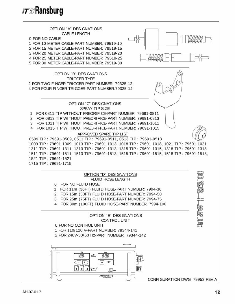
CONFIGURATION DWG. 79953 REV A
OPTION "A" DESIGNATIONSCABLE LENGTH
0 FOR NO CABLE1 FOR 10 METER CABLE-PART NUMBER: 79519-102 FOR 15 METER CABLE-PART NUMBER: 79519-153 FOR 20 METER CABLE-PART NUMBER: 79519-204 FOR 25 METER CABLE-PART NUMBER: 79519-255 FOR 30 METER CABLE-PART NUMBER: 79519-30
OPTION "B" DESIGNATIONSTRIGGER TYPE
2 FOR TWO FINGER TRIGGER-PART NUMBER: 79325-124 FOR FOUR FINGER TRIGGER-PART NUMBER:79325-14
OPTION "C" DESIGNATIONSSPRAY TIP SIZE
1 FOR 0811 TIP WITHOUT PREORIFICE-PART NUMBER: 79691-08112 FOR 0813 TIP WITHOUT PREORIFICE-PART NUMBER: 79691-08133 FOR 1011 TIP WITHOUT PREORIFICE-PART NUMBER: 79691-10114 FOR 1015 TIP WITHOUT PREORIFICE-PART NUMBER: 79691-1015
OPTION "D" DESIGNATIONSFLUID HOSE LENGTH
0 FOR NO FLUID HOSE1 FOR 11m (36FT) FLUID HOSE-PART NUMBER: 7994-362 FOR 15m (50FT) FLUID HOSE-PART NUMBER: 7994-503 FOR 25m (75FT) FLUID HOSE-PART NUMBER: 7994-754 FOR 30m (100FT) FLUID HOSE-PART NUMBER: 7994-100
APPROVED SPARE TIP LIST0509 TIP : 79691-0509, 0511 TIP : 79691-0511, 0513 TIP : 79691-05131009 TIP : 79691-1009, 1013 TIP : 79691-1013, 1018 TIP : 79691-1018, 1021 TIP : 79691-10211311 TIP : 79691-1311, 1313 TIP : 79691-1313, 1315 TIP : 79691-1315, 1318 TIP : 79691-13181511 TIP : 79691-1511, 1513 TIP : 79691-1513, 1515 TIP : 79691-1515, 1518 TIP : 79691-1518,1521 TIP : 79691-15211715 TIP : 79691-1715
OPTION "E" DESIGNATIONSCONTROL UNIT
0 FOR NO CONTROL UNIT1 FOR 110/120 V-PART NUMBER: 79344-1412 FOR 240V-50/60 Hz-PART NUMBER: 79344-142

AH-07-01.7
THE ITW RANSBURGTHE ITW RANSBURGTHE ITW RANSBURGTHE ITW RANSBURGTHE ITW RANSBURGELECTROSTELECTROSTELECTROSTELECTROSTELECTROSTAAAAATICTICTICTICTICVECTOR AA90 PROCESSVECTOR AA90 PROCESSVECTOR AA90 PROCESSVECTOR AA90 PROCESSVECTOR AA90 PROCESS
This is a combined air/airless method forelectrostatically applying coatings to objects. TheVector AA90 Vector AA90 Vector AA90 Vector AA90 Vector AA90 system applies a high voltage DCcharge to the applicator electrode, creating anelectrostatic field between the electrode and thegrounded target. The target is electrically groundedthrough its support which may be either stationaryor moving.
A regulated high pressure fluid system deliverscoating material to the fluid nozzle and is atomizedby passing through an orifice under pressure. Theatomized spray particles become electricallycharged under the influence of the electrostaticfield surrounding the nozzle. The air supply to theapplicator aids in shaping the coating material intoa desired pattern. The charged particles areattracted to and deposited on the target object.The forces between the charged particles and thegrounded target are sufficient to turn most normaloverspray around and deposit it on the backsurface of the target. Therefore, a high percentageof the coating is deposited on the target.
One of the many features of the Vector AA90applicator system is that the electrical energy,which is available from the resistive chargingelectrode, is limited to the optimum level of safetyand efficiency. The system is incapable of releasingsufficient electrical or thermal energy during normaloperating conditions to cause ignition of specifichazardous materials in their most easily ignitedconcentrations in air.The power supply provides voltage output to theapplicator and contains controls for AC on/off,high voltage adjust, "one touch" triple setpoint, anddisplays kV and µA in real time.
INTRODUCTIONINTRODUCTIONINTRODUCTIONINTRODUCTIONINTRODUCTION
Vector AA90 Applicators - Introduction
1313131313
> When more than one waterborneapplicator is fed from a common isolatedfluid supply, there is a potential for electri-cal energy discharge through any otherapplicators when one applicator is trig-gered. Depending upon the systemcapacity, this discharge could be hazard-ous. Install only one spray applicator perisolated fluid supply system.
W A R N I N GW A R N I N GW A R N I N GW A R N I N GW A R N I N G!!!!!
As the applicator electrode approaches ground,the power supply and applicator circuitry causethe high voltage to approach zero while the currentapproaches its maximum value.

AH-07-01.7
Vector AA90 Applicators - Introduction
1414141414
NOTESNOTESNOTESNOTESNOTES

AH-07-01.7
Vector AA90 Applicators - Introduction
1515151515
110/120 VAC220/240 VAC
79513-13179513-132
-85 kV DC-85 kV DC
VoltageVoltageVoltageVoltageVoltageDesignationDesignationDesignationDesignationDesignation
MaximumMaximumMaximumMaximumMaximumOutputOutputOutputOutputOutput
90509050905090509050Part #Part #Part #Part #Part #
Control Unit Inputs / OutputsControl Unit Inputs / OutputsControl Unit Inputs / OutputsControl Unit Inputs / OutputsControl Unit Inputs / Outputs
79513-13X CONTROL79513-13X CONTROL79513-13X CONTROL79513-13X CONTROL79513-13X CONTROLUNIT ELECTRICALUNIT ELECTRICALUNIT ELECTRICALUNIT ELECTRICALUNIT ELECTRICALSPECIFICASPECIFICASPECIFICASPECIFICASPECIFICATIONSTIONSTIONSTIONSTIONS
Input Voltage:Input Voltage:Input Voltage:Input Voltage:Input Voltage: 100-240 VAC
Current:Current:Current:Current:Current: 1 A maximum RMS
Frequency:Frequency:Frequency:Frequency:Frequency: 50/60 Hz
Wattage:Wattage:Wattage:Wattage:Wattage: 40 watts (maximum)
Output Voltage:Output Voltage:Output Voltage:Output Voltage:Output Voltage: 20 VDC maximum
Current:Current:Current:Current:Current: 1A DC maximum
ElectricalElectricalElectricalElectricalElectrical
Height:Height:Height:Height:Height: 14.0cm (5.5-inches)
Width:Width:Width:Width:Width: 21.6cm (8.5-inches)
Depth:Depth:Depth:Depth:Depth: 19.1cm (7.5-inches)
Weight:Weight:Weight:Weight:Weight: 3.4 Kg (7.5 lbs.)
PhysicalPhysicalPhysicalPhysicalPhysical
Supply Air:Supply Air:Supply Air:Supply Air:Supply Air: 6.9 bar (100 psig) maximumPneumaticPneumaticPneumaticPneumaticPneumatic
SPECIFICASPECIFICASPECIFICASPECIFICASPECIFICATIONSTIONSTIONSTIONSTIONSSOLSOLSOLSOLSOLVENTBORNEVENTBORNEVENTBORNEVENTBORNEVENTBORNE(((((CASCADE)CASCADE)CASCADE)CASCADE)CASCADE)
Fluid Pressure:Fluid Pressure:Fluid Pressure:Fluid Pressure:Fluid Pressure: 193 bar (2800 psi) (maximum)
Fluid Flow Rate:Fluid Flow Rate:Fluid Flow Rate:Fluid Flow Rate:Fluid Flow Rate: Variable to 1,500 cc/minute(spray tip dependent)
Air Pressure:Air Pressure:Air Pressure:Air Pressure:Air Pressure: 6.9 bar(0-100 psi) (maximum)
Applicator Length:Applicator Length:Applicator Length:Applicator Length:Applicator Length: 25.9cm(10.2-inches)
Weight:Weight:Weight:Weight:Weight: 760g(1.67 lbs.)(Cascade)
Hose and Cable Lengths:Hose and Cable Lengths:Hose and Cable Lengths:Hose and Cable Lengths:Hose and Cable Lengths: 10m, 15m, 20m,25m, and 30m
Atomizer Assembly:Atomizer Assembly:Atomizer Assembly:Atomizer Assembly:Atomizer Assembly: 79580-0XXXX(See "Nozzle Selection Guide")
Operating Voltage:Operating Voltage:Operating Voltage:Operating Voltage:Operating Voltage: 85 kV maximum
Current Output:Current Output:Current Output:Current Output:Current Output:Cascade:Cascade:Cascade:Cascade:Cascade: 65 microamperes maximum
Paint Resistance:*Paint Resistance:*Paint Resistance:*Paint Resistance:*Paint Resistance:* .1 MΩ to ∞
Part Sprayability:Part Sprayability:Part Sprayability:Part Sprayability:Part Sprayability: Determine sprayability ofpart to be coated usingModel No. 76652 Test Equip-ment
(See "Paint, HV & SCI Test Equipment" servicemanual.)
Consumption:Consumption:Consumption:Consumption:Consumption: 83 dB(A) @ 2.1 bar(30 psig)
Wetted Parts:Wetted Parts:Wetted Parts:Wetted Parts:Wetted Parts: Nylon, Acetal, StainlessSteel, Teflon, and Carbide
*****(Use Model No. 76652, Test Equipment)
Environmental/PhysicalEnvironmental/PhysicalEnvironmental/PhysicalEnvironmental/PhysicalEnvironmental/Physical
ElectricalElectricalElectricalElectricalElectrical
MechanicalMechanicalMechanicalMechanicalMechanical
Sound LevelSound LevelSound LevelSound LevelSound Level
79580-0XXXX79580-0XXXX
79513-13179513-132
For Use WithFor Use WithFor Use WithFor Use WithFor Use With90509050905090509050
Part #Part #Part #Part #Part #
Control Unit / ApplicatorControl Unit / ApplicatorControl Unit / ApplicatorControl Unit / ApplicatorControl Unit / ApplicatorCombinationsCombinationsCombinationsCombinationsCombinations

AH-07-01.7
Vector AA90 Applicators - Introduction
1616161616
Figure 1: AA90 Cascade Solventborne Electrostatic Spray Applicator Features - Air AssistFigure 1: AA90 Cascade Solventborne Electrostatic Spray Applicator Features - Air AssistFigure 1: AA90 Cascade Solventborne Electrostatic Spray Applicator Features - Air AssistFigure 1: AA90 Cascade Solventborne Electrostatic Spray Applicator Features - Air AssistFigure 1: AA90 Cascade Solventborne Electrostatic Spray Applicator Features - Air Assist
12345
No.No.No.No.No. DescriptionDescriptionDescriptionDescriptionDescription
Cap/ElectrodeBarrel, HPReplaceable HookFan Air Adjust2-Finger Trigger
AA90 CASCADE SOLAA90 CASCADE SOLAA90 CASCADE SOLAA90 CASCADE SOLAA90 CASCADE SOLVENTBORNE ELECTROSTVENTBORNE ELECTROSTVENTBORNE ELECTROSTVENTBORNE ELECTROSTVENTBORNE ELECTROSTAAAAATIC SPRATIC SPRATIC SPRATIC SPRATIC SPRAYYYYYAPPLICAAPPLICAAPPLICAAPPLICAAPPLICATTTTTOR FEAOR FEAOR FEAOR FEAOR FEATURES - AIR ASSISTTURES - AIR ASSISTTURES - AIR ASSISTTURES - AIR ASSISTTURES - AIR ASSIST
678910
No.No.No.No.No. DescriptionDescriptionDescriptionDescriptionDescription
Trigger Lock AssemblyFluid Hose ConnectionAir Inlet ConnectionLow Voltage Cable ConnectionkV Setpoint Switch/Microamp Display

AH-07-01.7
Vector AA90 Applicatorss - Introduction
1717171717
Figure 2: 79513-13X Cascade Control Unit FeaturesFigure 2: 79513-13X Cascade Control Unit FeaturesFigure 2: 79513-13X Cascade Control Unit FeaturesFigure 2: 79513-13X Cascade Control Unit FeaturesFigure 2: 79513-13X Cascade Control Unit Features
123456
No.No.No.No.No. DescriptionDescriptionDescriptionDescriptionDescription
Setpoint Adjust ButtonskV Setpoint Adjust ButtonkV MeterHV On IndicatorµA MeterLocal/Remote Mode Indicator
79513-13X CASCADE CONTROL79513-13X CASCADE CONTROL79513-13X CASCADE CONTROL79513-13X CASCADE CONTROL79513-13X CASCADE CONTROL UNIT UNIT UNIT UNIT UNIT FEA FEA FEA FEA FEATURESTURESTURESTURESTURES
789101112
No.No.No.No.No. DescriptionDescriptionDescriptionDescriptionDescription
Interlock ConnectorAC Line ConnectorFusesGround LugStandard I/O ConnectorLow Voltage Cable Connector
AH-07-01.7
Vector AA90 Applicators - Introduction
1818181818
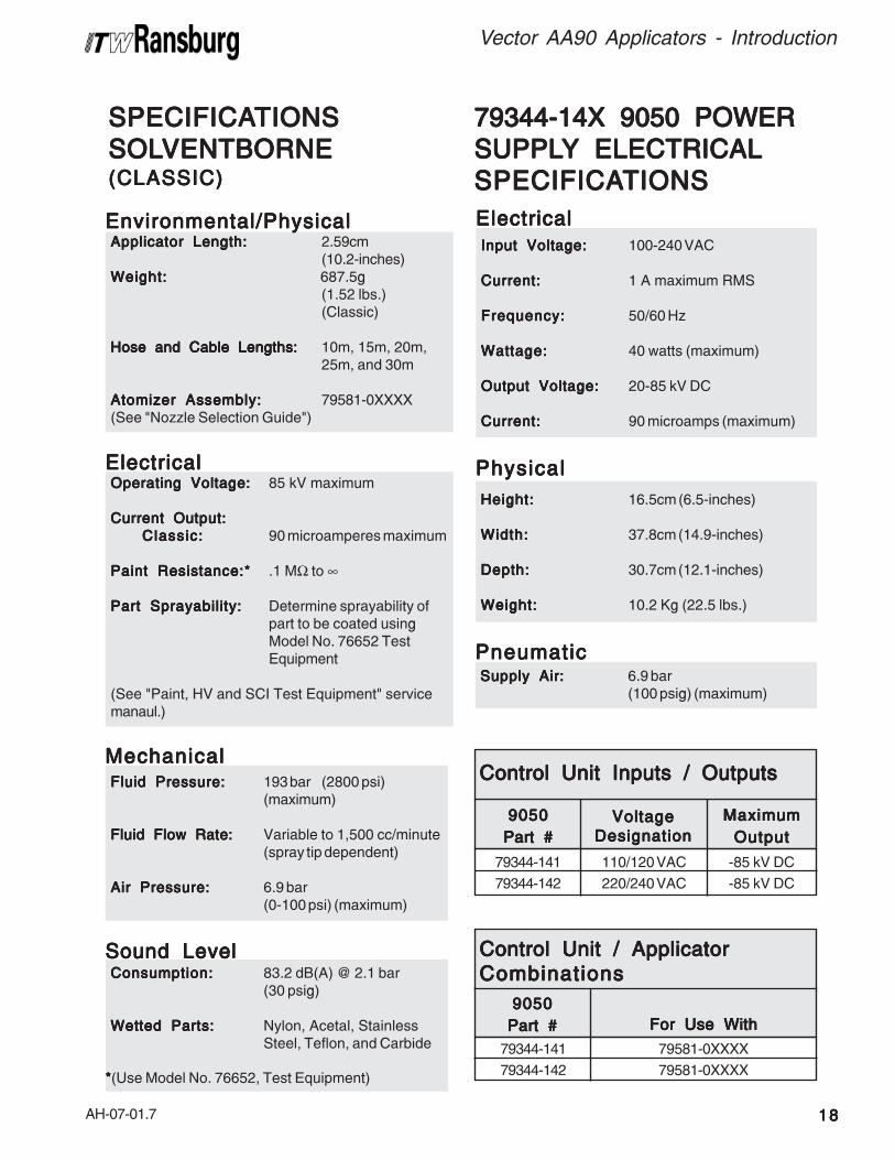
SPECIFICASPECIFICASPECIFICASPECIFICASPECIFICATIONSTIONSTIONSTIONSTIONSSOLSOLSOLSOLSOLVENTBORNEVENTBORNEVENTBORNEVENTBORNEVENTBORNE(C(C(C(C(CLASSICLASSICLASSICLASSICLASSIC)))))
Fluid Pressure:Fluid Pressure:Fluid Pressure:Fluid Pressure:Fluid Pressure: 193 bar (2800 psi)(maximum)
Fluid Flow Rate:Fluid Flow Rate:Fluid Flow Rate:Fluid Flow Rate:Fluid Flow Rate: Variable to 1,500 cc/minute(spray tip dependent)
Air Pressure:Air Pressure:Air Pressure:Air Pressure:Air Pressure: 6.9 bar(0-100 psi) (maximum)
Applicator Length:Applicator Length:Applicator Length:Applicator Length:Applicator Length: 2.59cm(10.2-inches)
Weight:Weight:Weight:Weight:Weight: 687.5g(1.52 lbs.)(Classic)
Hose and Cable Lengths:Hose and Cable Lengths:Hose and Cable Lengths:Hose and Cable Lengths:Hose and Cable Lengths: 10m, 15m, 20m,25m, and 30m
Atomizer Assembly:Atomizer Assembly:Atomizer Assembly:Atomizer Assembly:Atomizer Assembly: 79581-0XXXX(See "Nozzle Selection Guide")
Operating Voltage:Operating Voltage:Operating Voltage:Operating Voltage:Operating Voltage: 85 kV maximum
Current Output:Current Output:Current Output:Current Output:Current Output:Classic:Classic:Classic:Classic:Classic: 90 microamperes maximum
Paint Resistance:*Paint Resistance:*Paint Resistance:*Paint Resistance:*Paint Resistance:* .1 MΩ to ∞
Part Sprayability:Part Sprayability:Part Sprayability:Part Sprayability:Part Sprayability: Determine sprayability ofpart to be coated usingModel No. 76652 TestEquipment
(See "Paint, HV and SCI Test Equipment" servicemanaul.)
Consumption:Consumption:Consumption:Consumption:Consumption: 83.2 dB(A) @ 2.1 bar(30 psig)
Wetted Parts:Wetted Parts:Wetted Parts:Wetted Parts:Wetted Parts: Nylon, Acetal, StainlessSteel, Teflon, and Carbide
*****(Use Model No. 76652, Test Equipment)
Environmental/PhysicalEnvironmental/PhysicalEnvironmental/PhysicalEnvironmental/PhysicalEnvironmental/Physical
ElectricalElectricalElectricalElectricalElectrical
MechanicalMechanicalMechanicalMechanicalMechanical
Sound LevelSound LevelSound LevelSound LevelSound Level
79344-14X 9050 POWER79344-14X 9050 POWER79344-14X 9050 POWER79344-14X 9050 POWER79344-14X 9050 POWERSUPPLSUPPLSUPPLSUPPLSUPPLYYYYY ELECTRICAL ELECTRICAL ELECTRICAL ELECTRICAL ELECTRICALSPECIFICASPECIFICASPECIFICASPECIFICASPECIFICATIONSTIONSTIONSTIONSTIONS
Input Voltage:Input Voltage:Input Voltage:Input Voltage:Input Voltage: 100-240 VAC
Current:Current:Current:Current:Current: 1 A maximum RMS
Frequency:Frequency:Frequency:Frequency:Frequency: 50/60 Hz
Wattage:Wattage:Wattage:Wattage:Wattage: 40 watts (maximum)
Output Voltage:Output Voltage:Output Voltage:Output Voltage:Output Voltage: 20-85 kV DC
Current:Current:Current:Current:Current: 90 microamps (maximum)
ElectricalElectricalElectricalElectricalElectrical
Height:Height:Height:Height:Height: 16.5cm (6.5-inches)
Width:Width:Width:Width:Width: 37.8cm (14.9-inches)
Depth:Depth:Depth:Depth:Depth: 30.7cm (12.1-inches)
Weight:Weight:Weight:Weight:Weight: 10.2 Kg (22.5 lbs.)
PhysicalPhysicalPhysicalPhysicalPhysical
Supply Air:Supply Air:Supply Air:Supply Air:Supply Air: 6.9 bar(100 psig) (maximum)
PneumaticPneumaticPneumaticPneumaticPneumatic
110/120 VAC220/240 VAC
79344-14179344-142
-85 kV DC-85 kV DC
VoltageVoltageVoltageVoltageVoltageDesignationDesignationDesignationDesignationDesignation
MaximumMaximumMaximumMaximumMaximumOutputOutputOutputOutputOutput
90509050905090509050Part #Part #Part #Part #Part #
Control Unit Inputs / OutputsControl Unit Inputs / OutputsControl Unit Inputs / OutputsControl Unit Inputs / OutputsControl Unit Inputs / Outputs
79581-0XXXX79581-0XXXX
79344-14179344-142
For Use WithFor Use WithFor Use WithFor Use WithFor Use With90509050905090509050
Part #Part #Part #Part #Part #
Control Unit / ApplicatorControl Unit / ApplicatorControl Unit / ApplicatorControl Unit / ApplicatorControl Unit / ApplicatorCombinationsCombinationsCombinationsCombinationsCombinations

AH-07-01.7
Vector AA90 Applicators - Introduction
1919191919
Figure 3: AA90 Classic Solventborne Electrostatic Spray Applicator Features - Air AssistFigure 3: AA90 Classic Solventborne Electrostatic Spray Applicator Features - Air AssistFigure 3: AA90 Classic Solventborne Electrostatic Spray Applicator Features - Air AssistFigure 3: AA90 Classic Solventborne Electrostatic Spray Applicator Features - Air AssistFigure 3: AA90 Classic Solventborne Electrostatic Spray Applicator Features - Air Assist
12345
No.No.No.No.No. DescriptionDescriptionDescriptionDescriptionDescription
Cap/ElectrodeBarrel, HPReplaceable HookFan Air Adjust2-Finger Trigger
AA90 CLASSIC SOLAA90 CLASSIC SOLAA90 CLASSIC SOLAA90 CLASSIC SOLAA90 CLASSIC SOLVENTBORNE ELECTROSTVENTBORNE ELECTROSTVENTBORNE ELECTROSTVENTBORNE ELECTROSTVENTBORNE ELECTROSTAAAAATIC SPRATIC SPRATIC SPRATIC SPRATIC SPRAYYYYYAPPLICAAPPLICAAPPLICAAPPLICAAPPLICATTTTTOR FEAOR FEAOR FEAOR FEAOR FEATURES - AIR ASSISTTURES - AIR ASSISTTURES - AIR ASSISTTURES - AIR ASSISTTURES - AIR ASSIST
6789
No.No.No.No.No. DescriptionDescriptionDescriptionDescriptionDescription
Trigger Lock AssemblyFluid Hose ConnectionAir Inlet ConnectionsHigh Voltage Cable Connection

AH-07-01.7
Vector AA90 Applicators - Introduction
2020202020
Figure 4: 79344-14X 9050 Power Supply FeaturesFigure 4: 79344-14X 9050 Power Supply FeaturesFigure 4: 79344-14X 9050 Power Supply FeaturesFigure 4: 79344-14X 9050 Power Supply FeaturesFigure 4: 79344-14X 9050 Power Supply Features
12345678
No.No.No.No.No. DescriptionDescriptionDescriptionDescriptionDescription
kV MeterHigh Voltage On IndicatorReset ButtonµA MeterFault IndicatorOn-Off SwitchLocal Remote Mode Indicator"One Touch" kV Setpoint Button
79344-14X 9050 POWER SUPPL79344-14X 9050 POWER SUPPL79344-14X 9050 POWER SUPPL79344-14X 9050 POWER SUPPL79344-14X 9050 POWER SUPPLYYYYY FEA FEA FEA FEA FEATURESTURESTURESTURESTURES
910111213141516
No.No.No.No.No. DescriptionDescriptionDescriptionDescriptionDescription
kV Setpoint/Adjust ButtonsAir Flow Switch Connections (Low Flow)High Voltage Cable ConnectorStandard I/O ConnectorFusesGround LugAC Inlet ReceptableInterlock I/O Connector

AH-07-01.7
Vector AA90 Applicators - Installation
INSTINSTINSTINSTINSTALLAALLAALLAALLAALLATIONTIONTIONTIONTION
• Position all non-approved electrical apparatus(including, but not limited to, high voltage powersupplies, fluid pumps, and air compressors)outside of the hazardous location. See theappropriate country or local codes.
• Provide appropriate fire extinguishing equipment.
• Provide conductive flooring in all spray areas.
2121212121
SAFE INSTSAFE INSTSAFE INSTSAFE INSTSAFE INSTALLAALLAALLAALLAALLATIONTIONTIONTIONTION
• Ground the spray booth, the paint supply, andthe conveyor or work support.
• Ground all solvent and waste safety containers.
• Ground all work holders and hooks and keepthem free of paint.
• Ground the target object to a structural groundand not back to the applicator system. Ensurethat all target objects have a resistance toground of one megohm or LESS.
• Ensure that all elements of the coating systemare correctly grounded, connected, and located.
This information is intended ONLY to indicategeneral installation guidelines of this product andits working relationship to other ITW Ransburgsystem components. Each installation is uniqueand should be directed by an ITW Ransburgrepresentative.
TYPICAL AA90 CASCADETYPICAL AA90 CASCADETYPICAL AA90 CASCADETYPICAL AA90 CASCADETYPICAL AA90 CASCADEAPPLICAAPPLICAAPPLICAAPPLICAAPPLICATTTTTORORORORORINSTINSTINSTINSTINSTALLAALLAALLAALLAALLATIONTIONTIONTIONTIONConnect the low voltage cable to the control unit lowvoltage socket. Gently hand tighten the cable retainingnut. Connect the other end of the low voltage cable tothe applicator, using a wrench to tighten. Slide the cableboot over the nut.
The control unit may be connected through conduitwith an explosion-proof switch on or near thespray booth where it will be convenient to theoperator, or may be connected with a power corddepending upon application requirement.
> Install and route the hoses and cableso they are NOTNOTNOTNOTNOT exposed to tempera-tures in excess of 120°F and so that allhose bends are NOT LESSNOT LESSNOT LESSNOT LESSNOT LESS than a6-inch (15 cm) radius. Failure to complywith these guidelines could cause equip-ment malfunctions that might createHAZARDOUS CONDITIONS!HAZARDOUS CONDITIONS!HAZARDOUS CONDITIONS!HAZARDOUS CONDITIONS!HAZARDOUS CONDITIONS!
W A R N I N GW A R N I N GW A R N I N GW A R N I N GW A R N I N G!!!!!
> DO NOT DO NOT DO NOT DO NOT DO NOT overtighten the low voltagecable connection to the applicator. Dam-age to plastic parts may occur.
C A U T I O NC A U T I O NC A U T I O NC A U T I O NC A U T I O N!!!!!
> Target grounding wire must not beconnected directly to the ground lug of the9050. A seperate ground line must beused for each connection.
C A U T I O NC A U T I O NC A U T I O NC A U T I O NC A U T I O N!!!!!

AH-07-01.7
Vector AA90 Applicators - Installation
2222222222
Figure 5: Typical AA90 Cascade Applicator Installation FeaturesFigure 5: Typical AA90 Cascade Applicator Installation FeaturesFigure 5: Typical AA90 Cascade Applicator Installation FeaturesFigure 5: Typical AA90 Cascade Applicator Installation FeaturesFigure 5: Typical AA90 Cascade Applicator Installation Features
1234567
No.No.No.No.No. DescriptionDescriptionDescriptionDescriptionDescription
AC Line Cord (110/220)9050 Control UnitVector ApplicatorBall ValveAir Regulator W/Pressure GaugeAir/Water SeparatorMain Air Supply
TYPICALTYPICALTYPICALTYPICALTYPICAL AA90 CASCADE APPLICA AA90 CASCADE APPLICA AA90 CASCADE APPLICA AA90 CASCADE APPLICA AA90 CASCADE APPLICATTTTTOR INSTOR INSTOR INSTOR INSTOR INSTALLAALLAALLAALLAALLATIONTIONTIONTIONTIONFEAFEAFEAFEAFEATURESTURESTURESTURESTURES
891011121314
No.No.No.No.No. DescriptionDescriptionDescriptionDescriptionDescription
Fluid Supply (Grounded)Fluid RegulatorAir LineLow Voltage CableFluid LineTarget (Earth or Building Ground)9050 Ground (Seperate Earth or Building Ground)
R<1 Meg Ohm

AH-07-01.7
Vector AA90 Applicators - Installation
2323232323
1 79512-00 Enclosure Assembly, 9050 Cascade (Ref. - Not in Kit) --2 79493-00 Screw, Pan Head, 8-32 Phillips, Stainless Steel 83 79489-00 Bracket, Machined, 9050 Cascade 14 79488-00 Hinge, Machined, 9050 Cascade 15 79490-00 Bracket, Wall Mount, 9050 Cascade 26 7734-03 Lock Washer, Standard, Helical Spring 67 SI-0222-06 Service Instruction 1
Item #Item #Item #Item #Item #
79527-00 9050 MOUNTING KIT79527-00 9050 MOUNTING KIT79527-00 9050 MOUNTING KIT79527-00 9050 MOUNTING KIT79527-00 9050 MOUNTING KIT - P - P - P - P - PARARARARARTS LISTTS LISTTS LISTTS LISTTS LIST (Figure 6) (Figure 6) (Figure 6) (Figure 6) (Figure 6)
Part #Part #Part #Part #Part # DescriptionDescriptionDescriptionDescriptionDescription Q t yQ t yQ t yQ t yQ t y
> When mounting the control unit to aWhen mounting the control unit to aWhen mounting the control unit to aWhen mounting the control unit to aWhen mounting the control unit to awall or ceiling, the 79527-00 9050wall or ceiling, the 79527-00 9050wall or ceiling, the 79527-00 9050wall or ceiling, the 79527-00 9050wall or ceiling, the 79527-00 9050Mounting Kit should be used. IfMounting Kit should be used. IfMounting Kit should be used. IfMounting Kit should be used. IfMounting Kit should be used. Ifmounting to a non-metallic wall ormounting to a non-metallic wall ormounting to a non-metallic wall ormounting to a non-metallic wall ormounting to a non-metallic wall orceiling, the mounting screws must beceiling, the mounting screws must beceiling, the mounting screws must beceiling, the mounting screws must beceiling, the mounting screws must besecured to the wall or ceiling studs. Ifsecured to the wall or ceiling studs. Ifsecured to the wall or ceiling studs. Ifsecured to the wall or ceiling studs. Ifsecured to the wall or ceiling studs. Ifmounting to a metal wall or ceilingmounting to a metal wall or ceilingmounting to a metal wall or ceilingmounting to a metal wall or ceilingmounting to a metal wall or ceiling(such as a spray booth) the wall or(such as a spray booth) the wall or(such as a spray booth) the wall or(such as a spray booth) the wall or(such as a spray booth) the wall orceiling must be at least 0.050"ceiling must be at least 0.050"ceiling must be at least 0.050"ceiling must be at least 0.050"ceiling must be at least 0.050"(1.2mm) thick. In both cases, the(1.2mm) thick. In both cases, the(1.2mm) thick. In both cases, the(1.2mm) thick. In both cases, the(1.2mm) thick. In both cases, thecustomer must supply the screws tocustomer must supply the screws tocustomer must supply the screws tocustomer must supply the screws tocustomer must supply the screws toattach the brackets to the wall orattach the brackets to the wall orattach the brackets to the wall orattach the brackets to the wall orattach the brackets to the wall orceiling. These screws should be atceiling. These screws should be atceiling. These screws should be atceiling. These screws should be atceiling. These screws should be atleast 1/4" (6mm) in diameter.least 1/4" (6mm) in diameter.least 1/4" (6mm) in diameter.least 1/4" (6mm) in diameter.least 1/4" (6mm) in diameter.
C A U T I O NC A U T I O NC A U T I O NC A U T I O NC A U T I O N!!!!!MOUNTING THEMOUNTING THEMOUNTING THEMOUNTING THEMOUNTING THECONTROL UNITCONTROL UNITCONTROL UNITCONTROL UNITCONTROL UNIT
The Vector AA90 cascade applicators have anoptional Mounting Kit available 79527-00. This kitallows either top mounting or back mounting, witheither swing-away or fixed attachment.
There are four convenient ways of mounting theenclosure assembly using the included hardware(see Figure 6).

AH-07-01.7
Vector AA90 Applicators - Installation
2424242424
5
2
4
5
2
5
32
5
2
1
1
1
1
2
5
2
3
5
2
5
2
4
5
Figure 6: 79527-00 9050 Cascade EnclosuresFigure 6: 79527-00 9050 Cascade EnclosuresFigure 6: 79527-00 9050 Cascade EnclosuresFigure 6: 79527-00 9050 Cascade EnclosuresFigure 6: 79527-00 9050 Cascade Enclosures

AH-07-01.7
Vector AA90 Applicators - Installation
2525252525
ELECTRICAL NOISEELECTRICAL NOISEELECTRICAL NOISEELECTRICAL NOISEELECTRICAL NOISE
General Information - Classic orGeneral Information - Classic orGeneral Information - Classic orGeneral Information - Classic orGeneral Information - Classic orCascadeCascadeCascadeCascadeCascadeElectrical noise refers to stray electrical signals inthe atmosphere at various signal strengths andfrequencies that can affect the operation ofequipment. One of the best ways to prevent thisis to shield the equipment and cables within acontinuouscontinuouscontinuouscontinuouscontinuous ground envelope, such that anyincident noise will be conducted to earth groundbefore it can affect the circuit conductors.
For conductors inside the control unit or powersupply, the grounded enclosures provide thisenvelope. For the cables that connect the applicatorto the control unit or power supply, a shieldedcable has been used. The shield consists of anoverall foil shield in combination with an overallbraided shield. This provides the most effectiveshielding, as the foil covers the “holes” in the braid,and the braid allows for practical 360° terminationat both ends of the cable.
The AC input cord is not shielded, but instead isdirected to an AC line filter as soon as it enters thecabinet. This method filters out any noise thatcomes in on the AC line. For maximum noiseimmunity the AC line should connect to the filter assoon as it enters the cabinet with as short of leadsas possible. Additional noise protection can beprovided by running the AC input line to the controlpanel in grounded conduit.
For maximum noise protection any user suppliedinput/output (I/O) wiring should be made usingshielded cable (or conduit) which is connected toearth ground in a continuous 360° fashion at bothends. The best way to do this is to use a connector(conduit fitting) at each end of the cable (conduit)that makes contact to the shield (conduit) in a full360° circle around the cable (conduit) and makescontact to the grounded enclosure in the samefashion. Connecting the drain wire of a shield to aground point on or in the cabinet (usually referredto as pigtailing) is not an effective method ofshielding and actually makes things worse (seeFigure 7).
It is recommended that all AC I/O (interlocks) berun in conduit. If desired and codes permit, cablingmay be used for these signals, but for maximumnoise immunity the cabling must contain overallfoil and braided shields and be terminated asdescribed in the preceding paragraph.
Cable is recommended for the DC I/O (high voltageoutput signal, fault output signal). Again, formaximum noise immunity the cabling must containoverall foil and braided shields and be terminatedin a continuous 360° manner as described above.Special fittings have been provided on the controlpanel for termination of these cables at that point.The use of these fittings is described in thecorresponding sections of this manual.
Using the methods described above, the 9050Control Unit and Power Supply have beensuccessfully tested to the stringent standards ofthe Electromagnetic Compatibility Directive of theEuropean Union. The results conclude that theseunits are neither a source of electrical noise noraffected by electrical noise when the abovemethods are utilized.
Figure 7: Pigtailing ConnectionFigure 7: Pigtailing ConnectionFigure 7: Pigtailing ConnectionFigure 7: Pigtailing ConnectionFigure 7: Pigtailing Connection

AH-07-01.7
Vector AA90 Applicators - Installation
2626262626
I/O CONNECTIONSI/O CONNECTIONSI/O CONNECTIONSI/O CONNECTIONSI/O CONNECTIONS(CASCADE UNITS)(CASCADE UNITS)(CASCADE UNITS)(CASCADE UNITS)(CASCADE UNITS)
For maximum noise immunity, I/O wiring shouldbe run in conduit or cables having a foil shield withan overall braided shield. The foil shield provides100% shielding, while the braid provides a meansof making proper 360° shield terminations at thecable to cabinet connection points. To make I/Oconnections using shielded cable, perform thefollowing:
1. Remove the cable grommet hardware from thedesired I/O connector housing (see Figure 8).
2. Route the desired length of I/O cable throughthe connector housing and mark 1-inch span ofcable that passes through connector housing tobe stripped to braid (see Figure 9).
3. Remove cable and strip marked 1-inch sectionto cable braid.
4. Slide the cable grommet hardware onto thecable in the order shown in Figure 8.
5. Route the cable back through the connectorhousing and connect its wires to the desired I/Oterminals inside the 9050 Control Unit or powersupply.
6. Tighten the cable grommet ensuring thegrommet spring makes 360° contact with theexposed braid of the cable, for maximum noiseimmunity.
7. For maximum noise immunity, connect thebraid of the cable to earth ground at the endopposite the control unit or power supply.
Figure 9: I/O Cable StrippingFigure 9: I/O Cable StrippingFigure 9: I/O Cable StrippingFigure 9: I/O Cable StrippingFigure 9: I/O Cable Stripping
Figure 8: Cable GrommetFigure 8: Cable GrommetFigure 8: Cable GrommetFigure 8: Cable GrommetFigure 8: Cable Grommet

AH-07-01.7
Vector AA90 Applicators - Installation
2727272727
AC INPUTAC INPUTAC INPUTAC INPUTAC INPUTCONNECTIONSCONNECTIONSCONNECTIONSCONNECTIONSCONNECTIONS(((((CASCADE UNITSCASCADE UNITSCASCADE UNITSCASCADE UNITSCASCADE UNITS)))))
For non-conduit installations, plug the detachableAC line cord into the receptacle on the rear of thecontrol unit. Plug the other end of the line cord intoa properly grounded 120 volt AC outlet.
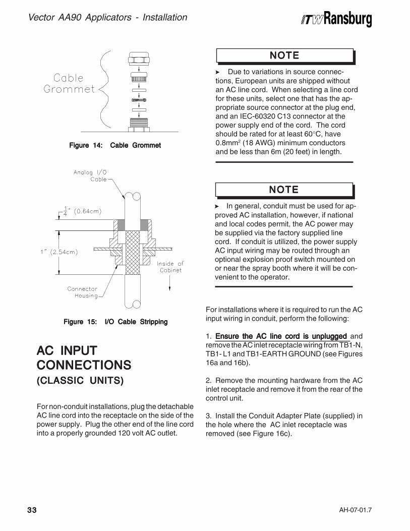
> Due to variations in source connec-tions, European units are shipped withoutan AC line cord. When selecting a line cordfor these units, select one that has the ap-propriate source connector at the plug end,and an IEC-60320 C13 connector at thecontrol unit end of the cord. The cordshould be rated for at least 60°C, have0.8mm2 (18 AWG) minimum conductors,and be less than 6m (20 ft.) in length.
NOTENOTENOTENOTENOTE
2. Remove the mounting hardware from the ACinlet receptacle and remove it from the rear of thecontrol unit.
3. Install the Conduit Adapter Plate (supplied) inthe hole where the AC inlet receptacle was removed(see Figure 10c).
4. Install the AC input wiring (0.8mm2 (18 AWG)minimum) through the Conduit Adapter Plate usingconduit and wire to TB1 as follows:
Hot/Line to TB1-L1 Neutral/Common to TB1-N Ground to TB1-EARTH GROUND
> In general, conduit must be used for ap-proved AC installation, however, if nationaland local codes permit, the AC power maybe supplied via the factory supplied linecord. If conduit is utilized, the control unitAC input wiring may be routed through anoptional explosion proof switch mounted onor near the spray booth where it will be con-venient to the operator.
NOTENOTENOTENOTENOTE
For installations where it is required to run the ACinput wiring in conduit, perform the following:
1. Ensure the AC line cord is unpluggedEnsure the AC line cord is unpluggedEnsure the AC line cord is unpluggedEnsure the AC line cord is unpluggedEnsure the AC line cord is unplugged andremove the AC inlet receptacle wiring from TB1-N,TB1- L1, and TB1-EARTH GROUND (see Figures10a and 10b).
INTERLOCKSINTERLOCKSINTERLOCKSINTERLOCKSINTERLOCKS
Interlocks required by code are as follows:
• Booth fan interlock - When the booth fan is on,a contact closure is made.
• Conveyor interlock - when the conveyor ismoving a contact closure is made.
• Solvent interlock - When solvent supply to theapplicator is off, a contact closure is made.
> When using conduit to route the AC in-put wiring to the control unit, the last severalfeet of conduit attached to the control unitshould be of a flexible type, such that thecontrol unit chassis can still be slid out of itsenclosure for testing and set-up purposes.
NOTENOTENOTENOTENOTE
Safety GroundSafety GroundSafety GroundSafety GroundSafety GroundCrimp the appropriate terminal onto the groundwire assembly and install from the control unitground lug, located on the back of the control unit,to a true earth ground.

AH-07-01.7
Vector AA90 Applicators - Installation
2828282828
> Failure to connect interlocks could resultin fire or explosion.
W A R N I N GW A R N I N GW A R N I N GW A R N I N GW A R N I N G!!!!!
To install the control unit interlocks perform thefollowing:
1. Turn the control unit off and remove theTurn the control unit off and remove theTurn the control unit off and remove theTurn the control unit off and remove theTurn the control unit off and remove thefuses.fuses.fuses.fuses.fuses.
2. Loosen the front panel screws and slide thecontrol unit chassis out.
3. Using a small blade screwdriver, remove thefactory installed test jumper from TB1-L2 to TB1-L3.
4. Using a shielded cable for the interlock wiring(supplied by user), route through the interlockconnector on the rear of the control unit andterminate to TB1-L2 and TB1-L3 as shown inFigure 10a. The shielded cable must have aminimum rating of 300V and 105°C and itsconductors should be 0.8mm2 (18 AWG) minimum.Secure the cable to the interlock connector asdescribed in the "I/O Connectors" in this section,so that the shield of the cable is connected to thechassis of the enclosure.
> Never flush the applicator while highvoltage is on.
W A R N I N GW A R N I N GW A R N I N GW A R N I N GW A R N I N G!!!!!RELARELARELARELARELAYYYYY CONT CONT CONT CONT CONTACTACTACTACTACTOUTPUTSOUTPUTSOUTPUTSOUTPUTSOUTPUTS
A set of relay contacts for high voltage (CR1) andfault (CR2) conditions is provided at TB2-3 andTB2-1 (see Figure 10a). One end of these relaycontacts are connected together and alsoconnected to a source input terminal at TB2-2(see Figure 10c). When a source voltage ispresent at TB2-2 and either the high voltage is onor a fault condition occurs, the source voltage willbecome available at the output end of thecorresponding contact. Maximum contact ratingsare as follows:
> The interlock contacts (supplied byuser) should be rated for at least 1 amp at240 volts AC.
NOTENOTENOTENOTENOTE
> Some codes may require the interlockwiring to be run in conduit. In this caseshielded cable is not necessary, but theconductors used should still meet the rat-ings specified above.
NOTENOTENOTENOTENOTE
5. Slide the chassis back in, secure the frontpanel screws, and replace the fuses.
Max. Switching Capacity
Max. Operating Voltage
Max. Operating Current
MAXIMUM CONTMAXIMUM CONTMAXIMUM CONTMAXIMUM CONTMAXIMUM CONTACTACTACTACTACT RA RA RA RA RATINGSTINGSTINGSTINGSTINGS
62.5VA
125VAC
2A
A CA CA CA CA CDescriptionDescriptionDescriptionDescriptionDescription
60W
125VDC
2A
D CD CD CD CD C
When wiring to TB2, use a shielded cable androute the wiring through the standard I/O connectoras described in the "I/O Connectors" in this section.
> An internal 24VDC source voltage isavailable at TB2-4. Using a jumper wire,this voltage may be connected to TB2-2 tobe used as the source voltage for the relaycontact outputs. In this case, the total cur-rent sourced should not exceed 1 amp.
NOTENOTENOTENOTENOTE

AH-07-01.7
Vector AA90 Applicators - Installation
2929292929
Figure 10a: Location of Terminal BlocksFigure 10a: Location of Terminal BlocksFigure 10a: Location of Terminal BlocksFigure 10a: Location of Terminal BlocksFigure 10a: Location of Terminal BlocksTB1 and TB2TB1 and TB2TB1 and TB2TB1 and TB2TB1 and TB2
Figure 10b: Interlock SchematicFigure 10b: Interlock SchematicFigure 10b: Interlock SchematicFigure 10b: Interlock SchematicFigure 10b: Interlock Schematic
Figure 10c: Installation of Conduit AdapterFigure 10c: Installation of Conduit AdapterFigure 10c: Installation of Conduit AdapterFigure 10c: Installation of Conduit AdapterFigure 10c: Installation of Conduit AdapterPlatePlatePlatePlatePlate
Figure 10d: Control Unit SchematicFigure 10d: Control Unit SchematicFigure 10d: Control Unit SchematicFigure 10d: Control Unit SchematicFigure 10d: Control Unit Schematic

AH-07-01.7
Vector AA90 Applicators - Installation
3030303030
LOW VOLLOW VOLLOW VOLLOW VOLLOW VOLTTTTTAGE CABLEAGE CABLEAGE CABLEAGE CABLEAGE CABLE
Connect the low voltage cable from the control unitto the applicator using a wrench to tighten.
Figure 11: Daisy Chained CableFigure 11: Daisy Chained CableFigure 11: Daisy Chained CableFigure 11: Daisy Chained CableFigure 11: Daisy Chained Cable
> DO NOT DO NOT DO NOT DO NOT DO NOT overtighten the low voltageconnection at the applicator. The plasticparts could be damaged.
C A U T I O NC A U T I O NC A U T I O NC A U T I O NC A U T I O N!!!!!
With the Vector design, multiple cables may beconnected together to create the length required,up to a maximum of 30m (100 ft.). To connect thecables, insert the male end of one cable into thefemale end of the other. Tighten both cableconnectors against each other using two (2) 16mm(5/8") open-end wrenches.
> The control unit power supply MUSTbe located at least 3 feet outside of thespray area. Install units in accordancewith the code requirements. (See localand national codes.)
W A R N I N GW A R N I N GW A R N I N GW A R N I N GW A R N I N G!!!!!
> The electrical discharge that is availablefrom the charging electrode must not exceed0.25 mJ of energy. To achieve this limit, anyflow of energy from the paint supply throughthe paint line to the applicator electrode mustbe prevented by grounding the paint line atthe applicator handle.
> Verify that the applicator handle isactually grounded before operating it! This isdone with a fully connected and operationalsystem, by placing one lead of an ohmmeterto the handle and the other to the buildingelectrical ground (cold water pipe, buildingstructure, steel, etc.). This reading shouldbe essentially zero.
> If a greater reading is obtained, checkthat the control unit is grounded. (See thecontrol unit manual for "Grounding Proce-dure".)
W A R N I N GW A R N I N GW A R N I N GW A R N I N GW A R N I N G!!!!!
TYPICAL AA90 CLASSICTYPICAL AA90 CLASSICTYPICAL AA90 CLASSICTYPICAL AA90 CLASSICTYPICAL AA90 CLASSICAPPLICAAPPLICAAPPLICAAPPLICAAPPLICATTTTTORORORORORINSTINSTINSTINSTINSTALLAALLAALLAALLAALLATIONTIONTIONTIONTION
Connect the low voltage cable to the control unitlow voltage socket. Gently hand tighten the cableretaining nut.
Connect the outlet from a regulator supply switchwith air hose to the applicator using a wrench.(The cascade unit uses reed switch triggering)
The control unit may be connected through conduitwith an explosion-proof switch on or near thespray booth where it will be convenient to theoperator, or may be connected with a power corddepending upon application requirement.
AH-07-01.7
Vector AA90 Applicators - Installation
3131313131
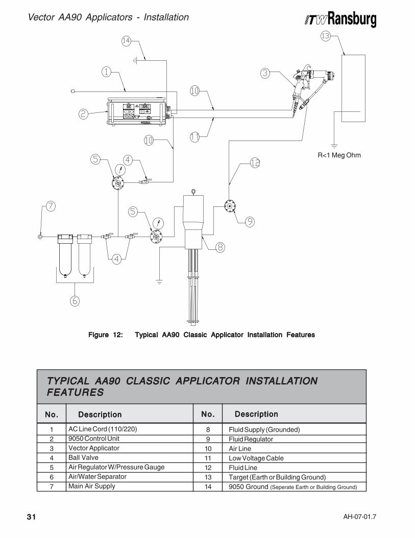
Figure 12: Typical AA90 Classic Applicator Installation FeaturesFigure 12: Typical AA90 Classic Applicator Installation FeaturesFigure 12: Typical AA90 Classic Applicator Installation FeaturesFigure 12: Typical AA90 Classic Applicator Installation FeaturesFigure 12: Typical AA90 Classic Applicator Installation Features
1234567
No.No.No.No.No. DescriptionDescriptionDescriptionDescriptionDescription
AC Line Cord (110/220)9050 Control UnitVector ApplicatorBall ValveAir Regulator W/Pressure GaugeAir/Water SeparatorMain Air Supply
TYPICALTYPICALTYPICALTYPICALTYPICAL AA90 CLASSIC APPLICA AA90 CLASSIC APPLICA AA90 CLASSIC APPLICA AA90 CLASSIC APPLICA AA90 CLASSIC APPLICATTTTTOR INSTOR INSTOR INSTOR INSTOR INSTALLAALLAALLAALLAALLATIONTIONTIONTIONTIONFEAFEAFEAFEAFEATURESTURESTURESTURESTURES
891011121314
No.No.No.No.No. DescriptionDescriptionDescriptionDescriptionDescription
Fluid Supply (Grounded)Fluid RegulatorAir LineLow Voltage CableFluid LineTarget (Earth or Building Ground)9050 Ground (Seperate Earth or Building Ground)
R<1 Meg Ohm

AH-07-01.7
Vector AA90 Applicators - Installation
3232323232
Figure 13: Typical Power Supply MountingFigure 13: Typical Power Supply MountingFigure 13: Typical Power Supply MountingFigure 13: Typical Power Supply MountingFigure 13: Typical Power Supply Mounting
The power supply may be free standing on any flatsurface or wall mounted (wall mount brackets notsupplied) as shown in Figure 13.
I/O CONNECTIONSI/O CONNECTIONSI/O CONNECTIONSI/O CONNECTIONSI/O CONNECTIONS(((((CLASSIC UNITSCLASSIC UNITSCLASSIC UNITSCLASSIC UNITSCLASSIC UNITS)))))
For maximum noise immunity, I/O wiring shouldbe run in conduit or cables having a foil shield withan overall braided shield. The foil shield provides100% shielding, while the braid provides a meansof making proper 360° shield terminations at thecable to cabinet connection points. To make I/Oconnections using shielded cable, perform thefollowing:
1. Remove the cable grommet hardware from thedesired I/O connector housing (see Figure 14).
2. Route the desired length of I/O cable throughthe connector housing and mark 1-inch span ofcable that passes through connector housing tobe stripped to braid (see Figure 15).
3. Remove cable and strip marked 1-inch sectionto cable braid.
4. Slide the cable grommet hardware onto thecable in the order shown in Figure 14.
5. Route the cable back through the connectorhousing and connect its wires to the desired I/Oterminals inside the 9050 Control Unit or powersupply.
6. Tighten the cable grommet ensuring thegrommet spring makes 360° contact with theexposed braid of the cable, for maximum noiseimmunity.
7. For maximum noise immunity, connect thebraid of the cable to earth ground at the endopposite the control unit or power supply.
> DO NOTDO NOTDO NOTDO NOTDO NOT locate the power supply nearor adjacent to heat producing equipmentsuch as ovens, high wattage lamps, etc.
C A U T I O NC A U T I O NC A U T I O NC A U T I O NC A U T I O N!!!!!
CLASSIC POWERCLASSIC POWERCLASSIC POWERCLASSIC POWERCLASSIC POWERSUPPLSUPPLSUPPLSUPPLSUPPLYYYYY INST INST INST INST INSTALLAALLAALLAALLAALLATIONTIONTIONTIONTION
AH-07-01.7
Vector AA90 Applicators - Installation
3333333333
Figure 15: I/O Cable StrippingFigure 15: I/O Cable StrippingFigure 15: I/O Cable StrippingFigure 15: I/O Cable StrippingFigure 15: I/O Cable Stripping
Figure 14: Cable GrommetFigure 14: Cable GrommetFigure 14: Cable GrommetFigure 14: Cable GrommetFigure 14: Cable Grommet
AC INPUTAC INPUTAC INPUTAC INPUTAC INPUTCONNECTIONSCONNECTIONSCONNECTIONSCONNECTIONSCONNECTIONS(((((CLASSIC UNITSCLASSIC UNITSCLASSIC UNITSCLASSIC UNITSCLASSIC UNITS)))))
For non-conduit installations, plug the detachableAC line cord into the receptacle on the side of thepower supply. Plug the other end of the line cordinto a properly grounded 120 volt AC outlet.
For installations where it is required to run the ACinput wiring in conduit, perform the following:
1. Ensure the AC line cord is unpluggedEnsure the AC line cord is unpluggedEnsure the AC line cord is unpluggedEnsure the AC line cord is unpluggedEnsure the AC line cord is unplugged andremove the AC inlet receptacle wiring from TB1-N,TB1- L1 and TB1-EARTH GROUND (see Figures16a and 16b).
2. Remove the mounting hardware from the ACinlet receptacle and remove it from the rear of thecontrol unit.
3. Install the Conduit Adapter Plate (supplied) inthe hole where the AC inlet receptacle wasremoved (see Figure 16c).
> Due to variations in source connec-tions, European units are shipped withoutan AC line cord. When selecting a line cordfor these units, select one that has the ap-propriate source connector at the plug end,and an IEC-60320 C13 connector at thepower supply end of the cord. The cordshould be rated for at least 60°C, have0.8mm2 (18 AWG) minimum conductorsand be less than 6m (20 feet) in length.
NOTENOTENOTENOTENOTE
> In general, conduit must be used for ap-proved AC installation, however, if nationaland local codes permit, the AC power maybe supplied via the factory supplied linecord. If conduit is utilized, the power supplyAC input wiring may be routed through anoptional explosion proof switch mounted onor near the spray booth where it will be con-venient to the operator.
NOTENOTENOTENOTENOTE
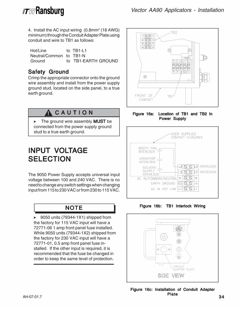
AH-07-01.7
Vector AA90 Applicators - Installation
3434343434
4. Install the AC input wiring (0.8mm2 (18 AWG)minimum) through the Conduit Adapter Plate usingconduit and wire to TB1 as follows:
Hot/Line to TB1-L1 Neutral/Common to TB1-N Ground to TB1-EARTH GROUND
Safety GroundSafety GroundSafety GroundSafety GroundSafety GroundCrimp the appropriate connector onto the groundwire assembly and install from the power supplyground stud, located on the side panel, to a trueearth ground.
INPUTINPUTINPUTINPUTINPUT VOL VOL VOL VOL VOLTTTTTAGEAGEAGEAGEAGESELECTIONSELECTIONSELECTIONSELECTIONSELECTION
The 9050 Power Supply accepts universal inputvoltage between 100 and 240 VAC. There is noneed to change any switch settings when changinginput from 115 to 230 VAC or from 230 to 115 VAC.
Figure 16a: Location of TB1 and TB2 InFigure 16a: Location of TB1 and TB2 InFigure 16a: Location of TB1 and TB2 InFigure 16a: Location of TB1 and TB2 InFigure 16a: Location of TB1 and TB2 InPower SupplyPower SupplyPower SupplyPower SupplyPower Supply
Figure 16b: TB1 Interlock WiringFigure 16b: TB1 Interlock WiringFigure 16b: TB1 Interlock WiringFigure 16b: TB1 Interlock WiringFigure 16b: TB1 Interlock Wiring
Figure 16c: Installation of Conduit AdapterFigure 16c: Installation of Conduit AdapterFigure 16c: Installation of Conduit AdapterFigure 16c: Installation of Conduit AdapterFigure 16c: Installation of Conduit AdapterPlatePlatePlatePlatePlate
> The ground wire assembly MUSTMUSTMUSTMUSTMUST beconnected from the power supply groundstud to a true earth ground.
C A U T I O NC A U T I O NC A U T I O NC A U T I O NC A U T I O N!!!!!
> 9050 units (79344-1X1) shipped fromthe factory for 115 VAC input will have a72771-06 1 amp front panel fuse installed.While 9050 units (79344-1X2) shipped fromthe factory for 230 VAC input will have a72771-01, 0.5 amp front panel fuse in-stalled. If the other input is required, it isrecommended that the fuse be changed inorder to keep the same level of protection.
NOTENOTENOTENOTENOTE

AH-07-01.7
Vector AA90 Applicators - Installation
3535353535
INTERLOCKSINTERLOCKSINTERLOCKSINTERLOCKSINTERLOCKS
Interlocks required by code are as follows:
• Booth Fan Interlock - When the booth fan is on,a contact closure is made.
• Conveyor Interlock - When the conveyor ismoving, a contact closure is made.
• Solvent Interlock - When solvent supply to thegun is off, a contact closure is made.
> ALWAYSALWAYSALWAYSALWAYSALWAYS ensure that high voltage isOFFOFFOFFOFFOFF before flushing the applicator withsolvent. NEVERNEVERNEVERNEVERNEVER flush the applicator withhigh voltage ONONONONON, as this is a severe firehazard and risk to personnel safety. It isrecommended that the high voltage controlbe interlocked with the solvent flush signalso that high voltage is automatically lockedout whenever flushing occurs. Consult yourauthorized ITW Ransburg representative forinformation on interlocking the high voltageOFF OFF OFF OFF OFF signal with the solvent flush signal.
W A R N I N GW A R N I N GW A R N I N GW A R N I N GW A R N I N G!!!!!
Figure 16d: Power Supply SchematicFigure 16d: Power Supply SchematicFigure 16d: Power Supply SchematicFigure 16d: Power Supply SchematicFigure 16d: Power Supply Schematic
As outlined in NFPA-33 and OSHA, the AC powerline must be series interlocked with both theexhaust fan and conveyor.
To install the power supply interlocks perform thefollowing:
1. Turn the power supply off, disconnect itTurn the power supply off, disconnect itTurn the power supply off, disconnect itTurn the power supply off, disconnect itTurn the power supply off, disconnect itfrom its AC source, and remove the fuses.from its AC source, and remove the fuses.from its AC source, and remove the fuses.from its AC source, and remove the fuses.from its AC source, and remove the fuses.
2. Open the power supply cabinet door.
> Failure to connect interlocks could resultin fire or explosion.
W A R N I N GW A R N I N GW A R N I N GW A R N I N GW A R N I N G!!!!!

AH-07-01.7
Vector AA90 Applicators - Installation
3636363636
> ALWAYS ALWAYS ALWAYS ALWAYS ALWAYS double check that the powersupply is unplugged from its AC outletbefore working with any internal wiring.
W A R N I N GW A R N I N GW A R N I N GW A R N I N GW A R N I N G!!!!!
3. Using a small blade screwdriver, remove thefactory installed test jumper from TB1-L2 to TB1-L3.
4. Using a shielded cable for the interlock wiring(supplied by user), route through the interlockconnector on the rear of the power supply andterminate TB1-L2 and TB1-L3 as shown in Figure16d. The shielded cable must have a minimumrating of 300V and 105°C and its conductorsshould be 0.8mm2 (18 AWG) minimum. Securethe cable to the interlock connector as describedin "I/O Connections" in this section so that theshield of the cable is connected to the chassis ofthe enclosure.
5. Secure the cabinet door, replace the fuses,and reconnect the AC source.
HIGH VOLHIGH VOLHIGH VOLHIGH VOLHIGH VOLTTTTTAGE CABLEAGE CABLEAGE CABLEAGE CABLEAGE CABLE
Position the applicator in the spray area and routethe high voltage cable to the power supply. Thecable should be routed so that it is not damaged byfoot and vehicle traffic and also so that it is notclose to areas of high temperature (129° F+). Theoperator should have free movement of theapplicator and all bend radii of the cable should notbe less than 6-inches (15cm). Connect the highvoltage cable to the power supply and tighten theretaining nut and set screw. If during the routing ofthe high voltage cable it is required to remove itfrom the applicator, care should be taken whenreinstalling so that the clip retaining the high voltagecable in the applicator is completely engaged andthe high voltage cable retention screw is tightenedto 5-7 lbs•in (.6-.8 Nm) (see Figure 17).
Figure 17: High Voltage Cable Removal andFigure 17: High Voltage Cable Removal andFigure 17: High Voltage Cable Removal andFigure 17: High Voltage Cable Removal andFigure 17: High Voltage Cable Removal andInstallationInstallationInstallationInstallationInstallation
> Some codes may require the interlockwiring to be run in conduit. In this case,shielded cable is not necessary, but theconductors used should still meet the rat-ings specified above.
NOTENOTENOTENOTENOTE
> The interlock contacts (supplied byuser) should be rated for at least 1 amp at240VAC.
NOTENOTENOTENOTENOTE
> The power supply must be off when theapplicator is removed or reinstalled.
W A R N I N GW A R N I N GW A R N I N GW A R N I N GW A R N I N G!!!!!
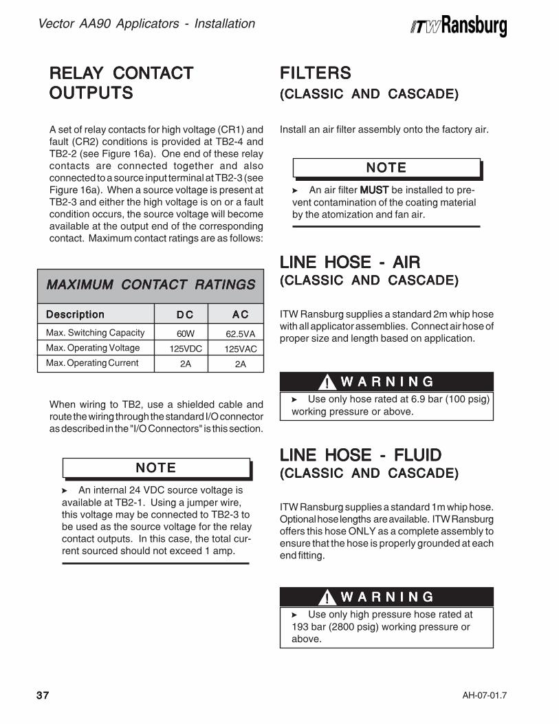
AH-07-01.7
Vector AA90 Applicators - Installation
3737373737
LINE HOSE - AIRLINE HOSE - AIRLINE HOSE - AIRLINE HOSE - AIRLINE HOSE - AIR(((((CLASSIC AND CASCADECLASSIC AND CASCADECLASSIC AND CASCADECLASSIC AND CASCADECLASSIC AND CASCADE)))))
ITW Ransburg supplies a standard 2m whip hosewith all applicator assemblies. Connect air hose ofproper size and length based on application.
RELARELARELARELARELAYYYYY CONT CONT CONT CONT CONTACTACTACTACTACTOUTPUTSOUTPUTSOUTPUTSOUTPUTSOUTPUTS
A set of relay contacts for high voltage (CR1) andfault (CR2) conditions is provided at TB2-4 andTB2-2 (see Figure 16a). One end of these relaycontacts are connected together and alsoconnected to a source input terminal at TB2-3 (seeFigure 16a). When a source voltage is present atTB2-3 and either the high voltage is on or a faultcondition occurs, the source voltage will becomeavailable at the output end of the correspondingcontact. Maximum contact ratings are as follows:
When wiring to TB2, use a shielded cable androute the wiring through the standard I/O connectoras described in the "I/O Connectors" is this section.
FILFILFILFILFILTERSTERSTERSTERSTERS(((((CLASSIC AND CASCADECLASSIC AND CASCADECLASSIC AND CASCADECLASSIC AND CASCADECLASSIC AND CASCADE)))))
Install an air filter assembly onto the factory air.
Max. Switching Capacity
Max. Operating Voltage
Max. Operating Current
MAXIMUM CONTMAXIMUM CONTMAXIMUM CONTMAXIMUM CONTMAXIMUM CONTACTACTACTACTACT RA RA RA RA RATINGSTINGSTINGSTINGSTINGS
62.5VA
125VAC
2A
A CA CA CA CA CDescriptionDescriptionDescriptionDescriptionDescription
60W
125VDC
2A
D CD CD CD CD C
> An internal 24 VDC source voltage isavailable at TB2-1. Using a jumper wire,this voltage may be connected to TB2-3 tobe used as the source voltage for the relaycontact outputs. In this case, the total cur-rent sourced should not exceed 1 amp.
NOTENOTENOTENOTENOTE
> An air filter MUSTMUSTMUSTMUSTMUST be installed to pre-vent contamination of the coating materialby the atomization and fan air.
NOTENOTENOTENOTENOTE
> Use only hose rated at 6.9 bar (100 psig)working pressure or above.
W A R N I N GW A R N I N GW A R N I N GW A R N I N GW A R N I N G!!!!!
> Use only high pressure hose rated at193 bar (2800 psig) working pressure orabove.
W A R N I N GW A R N I N GW A R N I N GW A R N I N GW A R N I N G!!!!!
LINE HOSE - FLUIDLINE HOSE - FLUIDLINE HOSE - FLUIDLINE HOSE - FLUIDLINE HOSE - FLUID(((((CLASSIC AND CASCADECLASSIC AND CASCADECLASSIC AND CASCADECLASSIC AND CASCADECLASSIC AND CASCADE)))))
ITW Ransburg supplies a standard 1m whip hose.Optional hose lengths are available. ITW Ransburgoffers this hose ONLY as a complete assembly toensure that the hose is properly grounded at eachend fitting.

AH-07-01.7
Vector AA90 Applicators - Installation
3838383838
NOTESNOTESNOTESNOTESNOTES
AH-07-01.7
Vector AA90 Applicators - Operation
OPERAOPERAOPERAOPERAOPERATIONTIONTIONTIONTION
3939393939
SAFE OPERASAFE OPERASAFE OPERASAFE OPERASAFE OPERATIONTIONTIONTIONTION
• Ground all operators by requiring that they holdthe applicator handle with a bare hand.
• Ground operators and all other persons inspray areas by requiring that they wear conduc-tive soled shoes or grounding straps.
• Have exhaust fans operating while spraying.
• Exhaust fans must be interlocked with thecontrol unit or Aviator.
• See that no more than one gallon of solvent persafety container per operator is inside of thehazard location.
• If ANY symptom of improper operation occurs,suspend use of the unit until the problem hasbeen diagnosed and corrected. See "Trouble-shooting Guide" or contact your authorizedITW Ransburg representative.
• Ground MUST be maintained during the additionof fluid to any supply container! Whenevertransferring flammable fluid from one containerto another, both containers MUST be properlyconnected to a proven ground first and then toeach other. Personnel executing such atransfer MUST also be grounded.
• A chemical reaction, resulting in the possibilityof a pressure EXPLOSION, may occur if 1, 1,1-Trichloroethane, Methylene Chloride, or otherHalogenated Hydrocarbon Solvents are usedin PRESSURIZABLE FLUID SYSTEMShaving ALUMINUM or GALVANIZEDWETTED PARTS. Such an explosion couldcause DEATH, serious BODILY INJURY and/or substantial property damage. Consult yourfluid supplier to determine the chemical contentof your solvents. (See "HHC Explosion HazardDanger Sign" and "Halogenated HydrocarbonSafety Bulletin".)
• Never flush the applicator with solvent whileelectrostatics are on. Failure to turn offelectrostatics while flushing may cause anIGNITION HAZARD.
THE RIGHT TECHNIQUETHE RIGHT TECHNIQUETHE RIGHT TECHNIQUETHE RIGHT TECHNIQUETHE RIGHT TECHNIQUE
Following are some basic electrostatic spraytechniques. Depending on the spray target, it maybe necessary to adjust the technique.
Spray Width DeterminationSpray Width DeterminationSpray Width DeterminationSpray Width DeterminationSpray Width DeterminationThe size of the object being coated is thedetermining factor in adjusting the spray pattern.The larger the object, the larger the required patternwidth. This is accomplished by fluid nozzleselection. Air adjustment is used to remove "tails"from the spray pattern and adjust the pattern size.
Applicator to TApplicator to TApplicator to TApplicator to TApplicator to Target Distancearget Distancearget Distancearget Distancearget DistanceThe distance between the applicator and the targetinfluences the appearance of the final finish of theobject. If the applicator is held too close, under100mm (approximately 4-inches), runs and sagswith excessive "bounce-back" may occur. If theapplicator is held too far from the object, theelectrostatic attraction is decreased. Normally,the best spacing between applicator and target isin the 150mm to 300mm area (6-inch to 12-inch).
> The degree of atomization is depen-dent on the viscosity of the paint formula-tion, the applied fluid pressure, and nozzleselection.
NOTENOTENOTENOTENOTE

AH-07-01.7
Vector AA90 Applicatorss - Operation
4040404040
OverlapOverlapOverlapOverlapOverlapFor the best "hiding" and uniformity of film thickness,the stroke overlap should be approximately 50%.There should be some overlap at edges of the partto increase edge coverage. Overlap requirementsmay vary widely with different paint formulationsand different compositions of objects being coated.
TTTTTriggeringriggeringriggeringriggeringriggeringApplicator triggering (ON/OFF) depends largelyon the desired results (the amount of wraparoundrequired, edge coating, etc.). If the front and backof the object are being coated, proper applicatortechnique can edge coat in some instances withoutmaking a specific pass for that purpose. Triggeringthe applicator before the target is directly in front ofthe applicator may cause heavy edge buildup onthe leading edge of the target due to the electrostaticattraction.
PREPPREPPREPPREPPREPARAARAARAARAARATIONTIONTIONTIONTION
PaintPaintPaintPaintPaintA selection of the proper paint mixture is essentialto electrostatic operation. Paint test equipmentmay be obtained through your ITW Ransburgrepresentative. For further paint formulation andtest procedures, consult your ITW Ransburgrepresentative and/or your paint supplier.
Fluid NozzleFluid NozzleFluid NozzleFluid NozzleFluid NozzleBecause of the design of the AA90 applicators, thefluid nozzle precision is paramount to properfunction. ITW Ransburg makes every effort toassure that all production of this part will meet thecritical design standards necessary for allapplications.
The selection of the best nozzle to apply a givencoating to a specific article with maximumefficiency is not an exact science. Testing isusually necessary and wide experience with manytypes of coating applications helps. Your ITWRansburg representative uses such experienceand actual laboratory testing when recommendinga nozzle for your application needs.
However, if parts, paints, or conveyor speeds arechanged, a different nozzle may be required forbest results. The following discussion and guidewill assist the user in making their own nozzleselection whenever it becomes necessary.Selection should always be verified by actualtests to determine optimum efficiencies.
Refer to "Nozzle Selection Guide" , Table I in thissection for the choice of spray width and spraycharacteristics appropriate to the size and type oftarget. The maximum nozzle flow capacitydepends on: the orifice size, the fluid pressure, thepaint viscosity, and the spraying temperature.Always remember, for maximum paint economyany nozzle selected should always be operated atthe lowest fluid pressure, which will give goodatomization and the required flow rate.
> ITW Ransburg recommends the useof a fluid filter in addition to the filter in theapplicator fluid line to reduce nozzleclogging.
C A U T I O NC A U T I O NC A U T I O NC A U T I O NC A U T I O N!!!!!
> The object being coated is maintainedat ground potential. The applicator opera-tor is also grounded, therefore, the opera-tor has as much attraction for the electro-static paint as the object. To prevent"wrap-back" always keep the applicatornozzle closer to the target than to theoperator.
C A U T I O NC A U T I O NC A U T I O NC A U T I O NC A U T I O N!!!!!

AH-07-01.7
Vector AA90 Applicators - Operation
4141414141
The AA90 applicator incorporates a new feature,that being a locating air cap. Refer to Figure 18 fora view showing the locating pin. This feature givesthe capability to spray with a fan pattern in eitherhorizontal or vertical positions.
Figure 18: Air Cap Alignment PinFigure 18: Air Cap Alignment PinFigure 18: Air Cap Alignment PinFigure 18: Air Cap Alignment PinFigure 18: Air Cap Alignment Pin
Figure 19: Pre-Orifice Seal Sizes DashFigure 19: Pre-Orifice Seal Sizes DashFigure 19: Pre-Orifice Seal Sizes DashFigure 19: Pre-Orifice Seal Sizes DashFigure 19: Pre-Orifice Seal Sizes DashIdentificationIdentificationIdentificationIdentificationIdentification
The first two digits of the nozzle dash number indicatethe spray pattern width in inches at a distance of 10-inches (254mm) from the target. The second twodigits indicate the orifice size in thousandths of inches.
For example: 79691-1015 has a 10-inches (254mm)spray pattern width and an orifice size of 0.015-inches(.38mm).
NozzleNozzleNozzleNozzleNozzleIdentificationIdentificationIdentificationIdentificationIdentification
79691-050979691-051179691-051379691-081179691-081379691-100979691-101179691-101379691-101579691-101879691-102179691-131179691-131379691-131579691-131879691-151179691-151379691-151579691-151879691-152179691-1715
5-in (127)
8-in. (203)
10-in. (254)
13-in. (330)
15-in. (381)
AA90 FluidAA90 FluidAA90 FluidAA90 FluidAA90 FluidNozzleNozzleNozzleNozzleNozzlePart #Part #Part #Part #Part #
PatternPatternPatternPatternPatternWidth atWidth atWidth atWidth atWidth at
10-in. (mm)10-in. (mm)10-in. (mm)10-in. (mm)10-in. (mm)
NozzleNozzleNozzleNozzleNozzleOrifice SizeOrifice SizeOrifice SizeOrifice SizeOrifice Size
in Inchesin Inchesin Inchesin Inchesin Inches(mm)(mm)(mm)(mm)(mm)
.009 (.23)
.011 (.28)
.013 (.33)
.011 (.28)
.013 (.33)
.009 (.23)
.011 (.28)
.013 (.33)
.015 (.38)
.018 (.46)
.021 (.53)
.011 (.28)
.013 (.33)
.015 (.38)
.018 (.46)
.011 (.28)
.013 (.33)
.015 (.38)
.018 (.46)
.021 (.53)
.015 (.38)
OperatingOperatingOperatingOperatingOperatingParametersParametersParametersParametersParameters
TABLE ITABLE ITABLE ITABLE ITABLE INOZZLE SELECTION GUIDENOZZLE SELECTION GUIDENOZZLE SELECTION GUIDENOZZLE SELECTION GUIDENOZZLE SELECTION GUIDE
79692-0179692-0279692-0379692-0479692-0679692-07
.1010" (.256mm)
.1021" (.307mm)
.0141" (.358mm)
.0161" (.409mm)
.0201" (.511mm)
.0221" (.561mm)
Part #Part #Part #Part #Part #
RestrictorRestrictorRestrictorRestrictorRestrictorOrif iceOrif iceOrif iceOrif iceOrif ice
SizeSizeSizeSizeSizeMatching Spray TipMatching Spray TipMatching Spray TipMatching Spray TipMatching Spray Tip
Part #Part #Part #Part #Part #
79691-0509, -100979691-0511, -0811, -1011, -1311, -151179691-0513, -0813, -1013, -1313, -151379691-1015, -1315, -1515, -171579691-1018, -1318, -151879691-1021, -1521
TABLE II - 79692-XX PRE-ORIFICE SEAL SIZESTABLE II - 79692-XX PRE-ORIFICE SEAL SIZESTABLE II - 79692-XX PRE-ORIFICE SEAL SIZESTABLE II - 79692-XX PRE-ORIFICE SEAL SIZESTABLE II - 79692-XX PRE-ORIFICE SEAL SIZES
Table II shows the available pre-orifice sizes. Thepre-orifice selected should be sized approximately.025mm (.001-inch) larger than the tip size opening.The pre-orifice can significantly increase the usefullspray life of the tip.
17-in. (432)

AH-07-01.7
Vector AA90 Applicators - Operation
4242424242
KV TEST JUMPERKV TEST JUMPERKV TEST JUMPERKV TEST JUMPERKV TEST JUMPER
To assist in testing and troubleshooting, a jumper(J8) has been added to the main PC board. Bycovering (shorting) both terminals of this jumper,the high voltage to the applicator can be activated.Thus, for testing and troubleshooting, high voltageoutput can be obtained without the need to triggerair through the applicator. After testing, the jumpermust be repositioned so that it covers only oneterminal (open) or the high voltage will stay on allthe time (see Figure 27 for location of test jumperJ8).
> If jumper J8 is left covering (shorting)both terminals, high voltage will be onwhenever AC power is turned on.
C A U T I O NC A U T I O NC A U T I O NC A U T I O NC A U T I O N!!!!!
FFFFFAULAULAULAULAULTTTTT DESCRIPTIONS DESCRIPTIONS DESCRIPTIONS DESCRIPTIONS DESCRIPTIONS
For in depth troubleshooting information on the9050, refer to SI-09-05SI-09-05SI-09-05SI-09-05SI-09-05. When a fault occurs, theFault Indicator on the front of the control unit willlight, a fault code will be displayed on the microampmeter and the 6 LED’s at the rear of the applicatorwill flash. Faults can be reset by pressing theReset button on the front of the control unit or bypressing and holding the kV switch at the rear ofthe applicator for 2-3 seconds.
Cable Fault (CF)Cable Fault (CF)Cable Fault (CF)Cable Fault (CF)Cable Fault (CF)This fault will occur if high voltage is active and themicroprocessor detects that no current is beingsupplied to the applicator. Typical causes includea broken or improperly connected cable, stuckpins on the plug assemblyor contaminatedcontacts on the barrel assembly. Other causescould include loose wiring in the control unit or afaulty cascade circuit in the applicator barrel.When this fault occurs, determine the cause of theproblem, then press the Reset button.
Figure 20: Cable Fault DisplayFigure 20: Cable Fault DisplayFigure 20: Cable Fault DisplayFigure 20: Cable Fault DisplayFigure 20: Cable Fault Display
Over VOver VOver VOver VOver Voltage Fault (OU)oltage Fault (OU)oltage Fault (OU)oltage Fault (OU)oltage Fault (OU)This fault will occur if the microprocessor detectsthe unit is trying to output voltage above thatrequired for the specific applicator type. If thisoccurs, reset the control unit. If this fault continuesto occur, replace the main PC board.
Figure 21: Over Voltage Fault DisplayFigure 21: Over Voltage Fault DisplayFigure 21: Over Voltage Fault DisplayFigure 21: Over Voltage Fault DisplayFigure 21: Over Voltage Fault Display

AH-07-01.7
Vector AA90 Applicators - Operation
4343434343
Figure 22: Safety Fault DisplayFigure 22: Safety Fault DisplayFigure 22: Safety Fault DisplayFigure 22: Safety Fault DisplayFigure 22: Safety Fault Display
Safety Fault (SF)Safety Fault (SF)Safety Fault (SF)Safety Fault (SF)Safety Fault (SF)If this fault occurs, the fault indicator at the controlunit will illuminate, a SF indication will show in theµA display and the LED on the rear of the applicatorwill flash. This fault will occur if the microprocessordetects the unit is trying to output voltage to theapplicator with no trigger or ground has been lostto the applicator. If this occurs, reset the fault fromthe applicator or control unit. If this fault occursrepeatedly upon reset, replace the main PC board.
Overload Fault (OL)Overload Fault (OL)Overload Fault (OL)Overload Fault (OL)Overload Fault (OL)This fault will occur if the overload feature is active(see "Overload Activation" previously in thissection) and the output current comes within 10uA or less of the maximum current. Remove thecondition causing excess microamps and resetthe fault. This may be caused by excessive paintoverspray on the applicator or the paint formulationmay be too conductive. If microamps currentdraws are typically in this range due to specialcircumstances, turn the overload feature off.
Current Limit Fault (CL)Current Limit Fault (CL)Current Limit Fault (CL)Current Limit Fault (CL)Current Limit Fault (CL)This fault will occur if the output current exceedsthe maximum current by more than 20 uA for 2-3seconds. If this occurs, reset the fault from theapplicator or control unit. If this fault occursrepeatedly, investigate the main PC board or
applicator barrel for the cause. This may be casuedby excessive paint overspray on the applicator orthe paint formaulation may be too conductive.
VVVVVoltage Feedback Fault (UF)oltage Feedback Fault (UF)oltage Feedback Fault (UF)oltage Feedback Fault (UF)oltage Feedback Fault (UF)This fault will occur if the microprocessor detectsa loss of the voltage feedback signal. If thisoccurs, reset the fault from the applicator or controlunit. If this fault occurs repeatedly, replace themain PC board.
Feedback Fault (FF)Feedback Fault (FF)Feedback Fault (FF)Feedback Fault (FF)Feedback Fault (FF)This fault will occur if the microprocessor detectsa loss of the current feedback signal. If thisoccurs, reset the fault from the applicator or controlunit. If this fault occurs repeatedly, replace themain PC board.
POWERING UPPOWERING UPPOWERING UPPOWERING UPPOWERING UPCONTROL UNITCONTROL UNITCONTROL UNITCONTROL UNITCONTROL UNIT(((((CASCADE UNITSCASCADE UNITSCASCADE UNITSCASCADE UNITSCASCADE UNITS)))))
When the AC power is turned on, the unit willdisplay the PC board applicator type number onthe kV setpoint display and the software revisionlevel in the µA display for 2-3 seconds.
Figure 23: Control Unit Start-Up DisplayFigure 23: Control Unit Start-Up DisplayFigure 23: Control Unit Start-Up DisplayFigure 23: Control Unit Start-Up DisplayFigure 23: Control Unit Start-Up Display

AH-07-01.7
Vector AA90 Applicators - Operation
4444444444
SETPOINTSETPOINTSETPOINTSETPOINTSETPOINT VOL VOL VOL VOL VOLTTTTTAGEAGEAGEAGEAGE
The Vector applicator system has three voltagesetpoints 1, 2, and 3. Each of these voltages canbe individually adjusted between 20 and full kVusing the + and - buttons on the front of the controlunit. When the applicator trigger is off, the presentsetpoint can be changed either from the controlunit or from the switch on the back of the applicator.
Setting and Changing theSetting and Changing theSetting and Changing theSetting and Changing theSetting and Changing theSetpoint at the Control UnitSetpoint at the Control UnitSetpoint at the Control UnitSetpoint at the Control UnitSetpoint at the Control UnitFrom the factory, Preset 1 is full minus 20 kV,Preset 2 is full kV minus 10, and Preset 3 is fullkV. For 79 full kV is 85 kV.
At the control unit with the applicator not triggered,press the 1, 2, or 3 button on the front panel of thecontrol unit. (See Figure 24 for positions of the kVsetpoint and adjust buttons.) The only place toadjust the kV of each setpoint is at the control unit.
Figure 24: Front View of Control UnitFigure 24: Front View of Control UnitFigure 24: Front View of Control UnitFigure 24: Front View of Control UnitFigure 24: Front View of Control Unit
> Setpoints cannot be adjusted below20 kV.
NOTENOTENOTENOTENOTE
DescriptionDescriptionDescriptionDescriptionDescriptionApplicator TypeApplicator TypeApplicator TypeApplicator TypeApplicator Type
0
ST ST ST ST STARARARARARTTTTT-UP-UP-UP-UP-UP DISPLA DISPLA DISPLA DISPLA DISPLAYYYYY
85 kV Cascade
When a kV setpoint button is pressed, the lightabove the button will light and the kV display willshow the present voltage for that setpoint. Thisindicates the unit is set to spray at that setpoint.To adjust the kV for the present setpoint, press the+ or - setpoint adjust buttons.
When the + or - setpoint adjust buttons are held inlonger than 1 second, the kV display will beginincrementing or decrementing in units of 5 insteadof 1.
Figure 25: Changing SetpointFigure 25: Changing SetpointFigure 25: Changing SetpointFigure 25: Changing SetpointFigure 25: Changing Setpoint
Changing the Setpoint at theChanging the Setpoint at theChanging the Setpoint at theChanging the Setpoint at theChanging the Setpoint at theApplicatorApplicatorApplicatorApplicatorApplicatorTo change the setpoint at the applicator, theapplicator must NOT be triggered. By pushing thekV button on the rear cover of the applicator, thesetpoint will change. If there are 2 green lights lit,setpoint 1 is active. If 2 green lights and 2 yellowlights are lit, setpoint 2 is active. If all lights are lit(2 green lights, 2 yellow lights, and 2 red lights)setpoint 3 is active.

AH-07-01.7
Vector AA90 Applicators - Operation
4545454545
> DO NOTDO NOTDO NOTDO NOTDO NOT turn the applicator off usingthe applicator button in place of interlockingwith a solvent supply for flushing. Theapplicator must be interlocked with solventsupply such that when the solvent is on toflush the applicator, there is no kV at theapplicator.
W A R N I N GW A R N I N GW A R N I N GW A R N I N GW A R N I N G!!!!!
Figure 26: View of Rear CoverFigure 26: View of Rear CoverFigure 26: View of Rear CoverFigure 26: View of Rear CoverFigure 26: View of Rear Cover
LOCKOUTSLOCKOUTSLOCKOUTSLOCKOUTSLOCKOUTS
There are lockouts that may be done at the PCboard (see Figure 27). These lockouts may beused individually or in combination as required. Ifthe jumpers are disconnected, the original functionsare re-enabled. After changing any jumpers, theAC power must be cycled for the new setting totake affect.
Figure 27: Lockout Jumper LocationFigure 27: Lockout Jumper LocationFigure 27: Lockout Jumper LocationFigure 27: Lockout Jumper LocationFigure 27: Lockout Jumper Location
Front Panel LockoutFront Panel LockoutFront Panel LockoutFront Panel LockoutFront Panel LockoutThis feature locks out any changes to the kVsetting from the front panel of the control unit.
1. Set the kV to the desired value using the frontpanel buttons. This must be set prior to installingthe jumper.
2. Turn AC power off and access the interior ofthe control unit.
3. Place the jumper across the two (2) pins atlocation 16 on the main PC board (see Figure 28).
4. Close the control unit and turn AC power backon. Pressing the front panel +, -, or setpointbuttons will now have no effect on the kV setting.
Figure 28: Jumper Location - Front PanelFigure 28: Jumper Location - Front PanelFigure 28: Jumper Location - Front PanelFigure 28: Jumper Location - Front PanelFigure 28: Jumper Location - Front PanelLockoutLockoutLockoutLockoutLockout
kV to the applicator can be turned off by pressingthe applicator kV button in for 2-3 seconds. Thiscan be done whether the applicator is triggered ornot and is useful if the kV needs to be turned off forspraying into recessed areas. When the kV isdisabled in this manner, the kV meter will readzero, OFF will be displayed in the microampmeter, and all kV setpoint indicator lights will bedisabled. Pressing the kV button in for another 2-3 seconds turns the kV to the applicator back on.
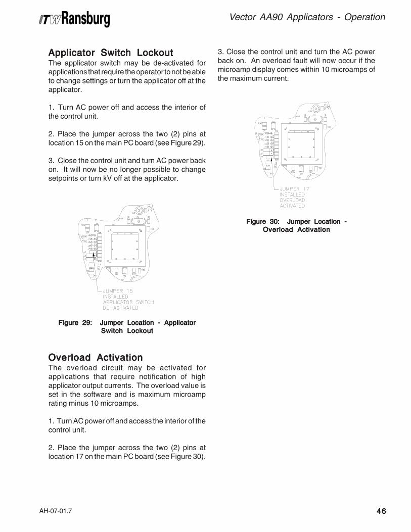
AH-07-01.7
Vector AA90 Applicators - Operation
4646464646
Applicator Switch LockoutApplicator Switch LockoutApplicator Switch LockoutApplicator Switch LockoutApplicator Switch LockoutThe applicator switch may be de-activated forapplications that require the operator to not be ableto change settings or turn the applicator off at theapplicator.
1. Turn AC power off and access the interior ofthe control unit.
2. Place the jumper across the two (2) pins atlocation 15 on the main PC board (see Figure 29).
3. Close the control unit and turn AC power backon. It will now be no longer possible to changesetpoints or turn kV off at the applicator.
Overload ActivationOverload ActivationOverload ActivationOverload ActivationOverload ActivationThe overload circuit may be activated forapplications that require notification of highapplicator output currents. The overload value isset in the software and is maximum microamprating minus 10 microamps.
1. Turn AC power off and access the interior of thecontrol unit.
2. Place the jumper across the two (2) pins atlocation 17 on the main PC board (see Figure 30).
Figure 29: Jumper Location - ApplicatorFigure 29: Jumper Location - ApplicatorFigure 29: Jumper Location - ApplicatorFigure 29: Jumper Location - ApplicatorFigure 29: Jumper Location - ApplicatorSwitch LockoutSwitch LockoutSwitch LockoutSwitch LockoutSwitch Lockout
Figure 30: Jumper Location -Figure 30: Jumper Location -Figure 30: Jumper Location -Figure 30: Jumper Location -Figure 30: Jumper Location -Overload ActivationOverload ActivationOverload ActivationOverload ActivationOverload Activation
3. Close the control unit and turn the AC powerback on. An overload fault will now occur if themicroamp display comes within 10 microamps ofthe maximum current.

AH-07-01.7
Vector AA90 Applicators - Operation
4747474747
BASIC OPERABASIC OPERABASIC OPERABASIC OPERABASIC OPERATIONTIONTIONTIONTION(CASCADE UNITS)(CASCADE UNITS)(CASCADE UNITS)(CASCADE UNITS)(CASCADE UNITS)
TTTTTriggeringriggeringriggeringriggeringriggeringHigh voltage is actuated by pulling the trigger tostart the flow of atomizing and fan control airthrough the applicator. When the applicator istriggered, a new switch in the applicator is activated.The kV setpoint is displayed on the kV display, theactual current draw on the µA display, and the highvoltage light illuminates. Under the µA display isa bar graph meter that illuminates according to theactual current draw.
Figure 31: µA Bar Graph Meter DisplayFigure 31: µA Bar Graph Meter DisplayFigure 31: µA Bar Graph Meter DisplayFigure 31: µA Bar Graph Meter DisplayFigure 31: µA Bar Graph Meter Display
The green and yellow regions of the bar graphmeter indicate output current is in the optimumrange for maximum transfer efficiency. The redregion of the bar graph indicates high output currentcausing decreased transfer efficiency.
The display at the rear of the applicator alsodoubles as a microamp bar graph meter when highvoltage is on (see Figure 30). Its' function is similarto that of the control unit bar graph display.
Figure 32: View of Applicator LED DisplayFigure 32: View of Applicator LED DisplayFigure 32: View of Applicator LED DisplayFigure 32: View of Applicator LED DisplayFigure 32: View of Applicator LED Display
Measuring "High VMeasuring "High VMeasuring "High VMeasuring "High VMeasuring "High Voltage On"oltage On"oltage On"oltage On"oltage On"TTTTTimeimeimeimeimeThe 9050 Power Supply records the amount oftime the high voltage is triggered on up to 99,999hours. These units are displayed in the kV and µAdisplays of the unit. There are two registers thatretain this information, one that may be reset, theother that is permanently retained in memory. Thenumber of hours the unit's high voltage has beenon may be displayed by depressing at the sametime the preset 1 and reset buttons. The displaywill show hours of use for 3 seconds. This is there-settable register.
Figure 33: Display In "High Voltage On" TimeFigure 33: Display In "High Voltage On" TimeFigure 33: Display In "High Voltage On" TimeFigure 33: Display In "High Voltage On" TimeFigure 33: Display In "High Voltage On" Time

AH-07-01.7
Vector AA90 Applicators - Operation
4848484848
DescriptionDescriptionDescriptionDescriptionDescriptionApplicator TypeApplicator TypeApplicator TypeApplicator TypeApplicator Type
6
STSTSTSTSTARARARARARTTTTT-UP-UP-UP-UP-UP DISPLA DISPLA DISPLA DISPLA DISPLAYYYYY
85 kV Classic
Figure 35: Power Supply Start-Up DisplayFigure 35: Power Supply Start-Up DisplayFigure 35: Power Supply Start-Up DisplayFigure 35: Power Supply Start-Up DisplayFigure 35: Power Supply Start-Up Display
STSTSTSTSTARARARARARTTTTT-UP-UP-UP-UP-UP(((((CLASSIC UNITSCLASSIC UNITSCLASSIC UNITSCLASSIC UNITSCLASSIC UNITS)))))
After all installation procedures are completed,operation of the applicator may begin. When theON-OFF switch is turned on, the kV display willshow the applicator type the 9050 Power Supplyis configured for and the microamp display willshow the current software revision level. Theseitems are displayed for about 2-3 seconds.
> DO NOTDO NOTDO NOTDO NOTDO NOT use a 65 kV Classic applica-tor with the 90 kV power supply.
W A R N I N GW A R N I N GW A R N I N GW A R N I N GW A R N I N G!!!!!
To reset this register, press the reset button whilethe hours are displayed. Pressing the preset 2and reset buttons at the same time will show thenumber of hours on the non-re-settable register.
Local/RemoteLocal/RemoteLocal/RemoteLocal/RemoteLocal/RemoteThe Vector product line is designed currently forapplicators only. The local/remote high voltagecontrol switch should be set to local for all Vectorapplicator applications.
Figure 34: High Voltage Control SwitchFigure 34: High Voltage Control SwitchFigure 34: High Voltage Control SwitchFigure 34: High Voltage Control SwitchFigure 34: High Voltage Control Switch
> The unit will not function if it is in remotemode without external inputs.
C A U T I O NC A U T I O NC A U T I O NC A U T I O NC A U T I O N!!!!!

AH-07-01.7
Vector AA90 Applicators - Operation
4949494949
BASIC OPERABASIC OPERABASIC OPERABASIC OPERABASIC OPERATIONSTIONSTIONSTIONSTIONS(CLASSIC UNITS)(CLASSIC UNITS)(CLASSIC UNITS)(CLASSIC UNITS)(CLASSIC UNITS)
TTTTTriggeringriggeringriggeringriggeringriggeringHigh voltage is actuated by pulling the trigger tostart the flow of atomizing and fan control airthrough the applicator. When the applicator istriggered, an air flow switch is activated, the kVsetpoint is displayed on the kV display, the actualcurrent draw on the µA display and the highvoltage light illuminates. Under the µA display isa bar graph meter that illuminates according to theactual current draw.
Figure 37: µA Bar Graph Meter DisplayFigure 37: µA Bar Graph Meter DisplayFigure 37: µA Bar Graph Meter DisplayFigure 37: µA Bar Graph Meter DisplayFigure 37: µA Bar Graph Meter Display
The green and yellow regions of the bar graphmeter indicate output current is in the optimumrange for maximum transfer efficiency. The redregion of the bar graph indicates high output currentcausing decreased transfer efficiency.
SETTING ANDSETTING ANDSETTING ANDSETTING ANDSETTING ANDADJUSTING OUTPUTADJUSTING OUTPUTADJUSTING OUTPUTADJUSTING OUTPUTADJUSTING OUTPUTVOLVOLVOLVOLVOLTTTTTAGEAGEAGEAGEAGE
The voltage on the 79344-1XX power supply isadjustable between 20 kV and full kV DC. Thefactory preset voltages are Preset 1 - full kV minus20 kV, Preset 2 - full kV minus 10 kV, and Preset3 - full kV.
The Vector applicator system has three voltagesetpoints 1, 2, and 3. Each of these setpoints canbe individually adjusted between 20 and full kVusing the + and - buttons on the front panel of thepower supply. When the + or - buttons are held inlonger than 1 second, the kV display will beginincrementing or decrementing in units of 5 insteadof 1.
When the applicator trigger is off, the presentsetpoint can be changed by pressing the 1, 2, or 3buttons on the front panel.
Figure 36: kV Adjust/Setpoint ButtonsFigure 36: kV Adjust/Setpoint ButtonsFigure 36: kV Adjust/Setpoint ButtonsFigure 36: kV Adjust/Setpoint ButtonsFigure 36: kV Adjust/Setpoint Buttons

AH-07-01.7
Vector AA90 Applicators - Operation
5050505050
Figure 38: Displaying "High Voltage On"Figure 38: Displaying "High Voltage On"Figure 38: Displaying "High Voltage On"Figure 38: Displaying "High Voltage On"Figure 38: Displaying "High Voltage On"TimeTimeTimeTimeTime
To reset this register, press the reset button whilethe hours are displayed.
To view the non-resettable register, press andhold the preset 2 and reset buttons at the sametime.
Figure 39: Local/Remote Mode ButtonFigure 39: Local/Remote Mode ButtonFigure 39: Local/Remote Mode ButtonFigure 39: Local/Remote Mode ButtonFigure 39: Local/Remote Mode Button
> If unit is in remote mode with no externalsignal, the unit will not function. The unitmust be in local mode.
C A U T I O NC A U T I O NC A U T I O NC A U T I O NC A U T I O N!!!!!
Measuring "High VMeasuring "High VMeasuring "High VMeasuring "High VMeasuring "High Voltage On"oltage On"oltage On"oltage On"oltage On"TTTTTimeimeimeimeimeThe 9050 Power Supply records the amount oftime the high voltage is triggered on up to 99,999hours. This value is displayed on the kV and µAdisplays of the unit. There are two registers thatretain this information, one that may be reset, theother that is permanently retained in memory. Thenumber of hours the unit's high voltage has beenon may be displayed by depressing at the sametime the preset 1 and reset buttons. The displaywill show hours of use for 3 seconds. This is theresettable register.
Local/Remote Mode ButtonLocal/Remote Mode ButtonLocal/Remote Mode ButtonLocal/Remote Mode ButtonLocal/Remote Mode ButtonThe 9050 Power Supply product line is designedcurrently for applicators only. The mode should beset to local for all Vector applicator applications.

AH-07-01.7
Vector AA90 Applicators - Operation
5151515151
TO REMOVE THETO REMOVE THETO REMOVE THETO REMOVE THETO REMOVE THEAPPLICAAPPLICAAPPLICAAPPLICAAPPLICATTTTTOR FROM THEOR FROM THEOR FROM THEOR FROM THEOR FROM THEWORK SITEWORK SITEWORK SITEWORK SITEWORK SITE
1. Flush the applicator. (Refer to "FlushingProcedures" in the "Maintenance" section.)
2. Ensure all fluid and air pressure hoses arebled from the system prior to removing line. Witha wrench, loosen and unscrew the fluid hose nut.Remove the fluid hose assembly.
3. With a wrench, lock the air fitting in place andloosen the air hose nut using a second wrench.Completely unscrew the nut and remove the airhose assembly.
4. Cascade Applicator: Cascade Applicator: Cascade Applicator: Cascade Applicator: Cascade Applicator: Loosen the low voltagecable nut from the plug assembly with a wrenchturning counter-clockwise and unscrew the nut byhand. Remove the low voltage cable by pulling itfrom the plug assembly.
Classic Applicator: Classic Applicator: Classic Applicator: Classic Applicator: Classic Applicator: Pull the clip on the highvoltage cable out with the blade of a screwdriver.Loosen cable set screw. Pull cable out of handle,
> ALWAYSALWAYSALWAYSALWAYSALWAYS remove the applicator fromthe work site for service or repair!
> Always ensure power to control unit/power supply is off prior to removing appli-cator from source.
> DO NOTDO NOTDO NOTDO NOTDO NOT use any silicone lubricants inorder to avoid paint defects.
C A U T I O NC A U T I O NC A U T I O NC A U T I O NC A U T I O N!!!!!
Figure 40: Removing Cascade ApplicatorFigure 40: Removing Cascade ApplicatorFigure 40: Removing Cascade ApplicatorFigure 40: Removing Cascade ApplicatorFigure 40: Removing Cascade Applicator
Figure 41: Removing Classic ApplicatorFigure 41: Removing Classic ApplicatorFigure 41: Removing Classic ApplicatorFigure 41: Removing Classic ApplicatorFigure 41: Removing Classic Applicator
5. Remove the applicator from the work site.
AH-07-01.7
Vector AA90 Applicators - Operation
5252525252
APPLICAAPPLICAAPPLICAAPPLICAAPPLICATTTTTOR REPOR REPOR REPOR REPOR REPAIRAIRAIRAIRAIR
All repairs should be made on a clean, flat surface.If a vise is used to hold parts during service orrepair, DO NOT clamp onto plastic parts andalways pad the vise jaws!
Apply dielectric grease (LSCH0009-00) to thefollowing parts when assembling:
• All O-Rings (Teflon o-rings do not need lu-brication)
• Needle Shaft Assembly• Packing Tube• Resistor Tube Assembly (Classic)• Air Valve Rod Assembly 79310-00
Apply sealant (7969-10) to the external threads ofthe following parts when assembling:
• Air Valve Retaining Nut
EQUIPMENT REQUIREDEQUIPMENT REQUIREDEQUIPMENT REQUIREDEQUIPMENT REQUIREDEQUIPMENT REQUIRED
• Special Multi-Purpose ApplicatorWrench 19749-00
• Air Cap Removal Tool 79642-00
• 2.5mm Wrenches 74133-00 (2)
• Nozzle Wrench 76428-00
• 3/32-inch Allen Wrench
• Open End Wrenches: 15/16, 7/8, 11/16,9/16, 7/16, 3/4, 3/8, and 1/4-inch
• Screwdriver (blade)
• Dielectric Grease LSCH0009-00
• Medium Strength Sealant 7969-10
• Plastic or Wood Dowel Rod, 5/16-inchdiameter

AH-07-01.7
MAINTENANCEMAINTENANCEMAINTENANCEMAINTENANCEMAINTENANCE
Vector AA90 Applicators - Maintenance
5353535353
SUITSUITSUITSUITSUITABLE SOLABLE SOLABLE SOLABLE SOLABLE SOLVENTSVENTSVENTSVENTSVENTSFOR CLEANINGFOR CLEANINGFOR CLEANINGFOR CLEANINGFOR CLEANINGVECTOR AA90VECTOR AA90VECTOR AA90VECTOR AA90VECTOR AA90APPLICAAPPLICAAPPLICAAPPLICAAPPLICATTTTTORSORSORSORSORS
When cleaning the Vector AA90 applicator, asuitable solvent for cleaning depends on the part(s)of the applicator to be cleaned and the material thatneeds to be removed. ITW Ransburg recommendsthat all exterior cleaning be done with non-polarsolvents to prevent a conductive residue on criticalcomponents. We also understand that some ofthese solvents do not always meet the cleaningneeds of some materials. If conductive polarsolvents are used to clean the applicatorcomponents, all residues must be removed usinga non-conductive non-polar solvent (i.e. high flashnaphtha). If there are any questions as to whatsolvents are best for cleaning, contact your localITW Ransburg distributor and/or your paintsupplier.
The AA90 applicator, air hoses, fluid hoses, andlow voltage/high voltage cable assemblies shouldnot be submerged or soaked in solvent. However,the outer surface of these items can be wiped witha suitable solvent. When the applicator isdisassembled into individual components, someof these items may be soaked in a suitable cleaningsolvent. The items that cannot be soaked arenoted throughout this manual. All electricalcomponents cannot be cleaned or soaked in anysolvents.
ROUTINE SCHEDULEROUTINE SCHEDULEROUTINE SCHEDULEROUTINE SCHEDULEROUTINE SCHEDULE
Follow these maintenance steps to extend thelife of the applicator and ensure efficientoperation.
Several TSeveral TSeveral TSeveral TSeveral Times Dailyimes Dailyimes Dailyimes Dailyimes Daily• Turn the control unit power OFF!
• Set the trigger stop lever and inspect the air capfor paint accumulation. Clean as frequently asnecessary with a soft bristled brush and asuitable solvent.
• Clean all insulating surfaces in the system.Remove paint accumulation from the exteriorof the applicator and low voltage or high voltagecable with a solvent dampened cloth.
> NEVERNEVERNEVERNEVERNEVER soak or submerge the electri-cal components of the applicator, i.e.,cascade barrel assembly, assembly orcable assembly. Damage and failure mayoccur.
C A U T I O NC A U T I O NC A U T I O NC A U T I O NC A U T I O N!!!!!
> ENSUREENSUREENSUREENSUREENSURE the power is OFFOFFOFFOFFOFF and thesystem is grounded before using solvent toclean ANYANYANYANYANY equipment. Relieve all fluidpressures.
> When using cleaning solvent, standardhealth and safety precautions should apply.
W A R N I N GW A R N I N GW A R N I N GW A R N I N GW A R N I N G!!!!!
> Cleaning of the exterior surfaces of theapplicator should be done with non-polarsolvents. If cleaning requires the use ofpolar solvents, the applicator should bewiped down with non-polar solvent prior togoing back into use.
C A U T I O NC A U T I O NC A U T I O NC A U T I O NC A U T I O N!!!!!

AH-07-01.7
Vector AA90 Applicators - Maintenance
5454545454
Daily (or at start of each shift)Daily (or at start of each shift)Daily (or at start of each shift)Daily (or at start of each shift)Daily (or at start of each shift)• Verify that ALL solvent safety containers are
grounded!
• Check within 20-feet of the point of operation(of the applicator) and remove or ground ALLloose or ungrounded objects.
• Inspect workholders for accumulated coatingmaterials (and remove such accumulations).
• Check that atomizer assembly is clean andundamaged.
• Check the applicator electrode for damage.
• Clean the fluid filter, if necessary.
• Turn the control unit power ON. Its green pilotshould light or Aviator will be audible.
• Run a voltage output test.
Applicator High VApplicator High VApplicator High VApplicator High VApplicator High Voltage Outputoltage Outputoltage Outputoltage Outputoltage OutputTTTTTest (Cascade/Classic)est (Cascade/Classic)est (Cascade/Classic)est (Cascade/Classic)est (Cascade/Classic)Use high voltage probe assembly (76652-01).
1. Set the meter dial to the kV scale. Plug the highvoltage probe into the side of the meter.
2. Attach the ground clamp to a proven earthground.
3. Make sure all grounded objects are at least2-feet away.
4. Line up the hole in the test probe and theelectrode. Slide the test probe straight over theelectrode wire of the applicator.
> Injury to personnel and damage toequipment is probable if the ground clip isNOT ATTACHEDNOT ATTACHEDNOT ATTACHEDNOT ATTACHEDNOT ATTACHED. This step MUSTMUSTMUSTMUSTMUST beaccomplished before voltage is applied.
W A R N I N GW A R N I N GW A R N I N GW A R N I N GW A R N I N G!!!!!
5. Holding the metal portion of the high voltageprobe in your hand, trigger the applicator so voltageexists at the electrode.
> To provide proper equipment to operatorground, the conductive handle of the probeMUSTMUSTMUSTMUSTMUST be held in the bare hand of theoperator. To avoid a shock hazard, themeter should NEVERNEVERNEVERNEVERNEVER be disconnected fromthe probe during high voltage contact.
W A R N I N GW A R N I N GW A R N I N GW A R N I N GW A R N I N G!!!!!
6. Read the voltage displayed on the meter.
7. Turn the voltage to the applicator OFF, and pullthe test probe straight off the electrode.
Shutdown (or at end of shift)Shutdown (or at end of shift)Shutdown (or at end of shift)Shutdown (or at end of shift)Shutdown (or at end of shift)1. Turn the control unit/power supply power OFF.
2. Turn the paint supply OFF.
3. Turn the shaping air supply OFF.
4. Wipe the applicator, cable, and hoses with arag and a suitable cleaning solvent.
5. Flush the fluid lines and applicator. Then bleedthe fluid pressure to zero, and allow the solvent toremain in the lines (see “Flushing Procedures” inthis section).
6. Set the trigger stop lever.

AH-07-01.7
Vector AA90 Applicators - Maintenance
5555555555
WeeklyWeeklyWeeklyWeeklyWeekly• Check the entire system for damage, leaks,
and paint accumulation.
• Clean the atomizer assembly.
APPLICAAPPLICAAPPLICAAPPLICAAPPLICATTTTTOR ASSEMBLOR ASSEMBLOR ASSEMBLOR ASSEMBLOR ASSEMBLYYYYYCLEANING PROCEDURECLEANING PROCEDURECLEANING PROCEDURECLEANING PROCEDURECLEANING PROCEDURE
Routine CleaningRoutine CleaningRoutine CleaningRoutine CleaningRoutine CleaningEquipment NeededEquipment NeededEquipment NeededEquipment NeededEquipment Needed
• An appropriate solvent
• Solvent safety container (grounded)
• Small soft-bristled brush
For efficient electrostatic operation, keep theapplicator’s exterior and low voltage / high voltagecable free of paint accumulation. This preventsthe loss of voltage to ground with a resultantreduction in transfer efficiency.
> If production downtime is to be short,the fluid lines may not require flushing (de-pending on the coating material beingused). If the solids in the coating settleslowly, the lines will not need to be flushedas soon after shutdown as with fast set-tling solids. The paint being used and thelength of downtime will determine the needfor flushing. Metallic paint and primer willrequire flushing sooner than other types ofcoating material.
NOTENOTENOTENOTENOTE
> If the coating material is fast settlingand the fluid lines are not flushed soonenough, the internal passages may be-come clogged. This can lead to excessivedowntime for repair.
C A U T I O NC A U T I O NC A U T I O NC A U T I O NC A U T I O N!!!!!
> Before cleaning the nozzle assembly,turn the control unit or power supply OFFOFFOFFOFFOFFand flush the fluid line with a compatiblesolvent until clean. Turn the paint and airsupplies OFFOFFOFFOFFOFF. Trigger the applicator torelieve both fluid and air pressures.
C A U T I O NC A U T I O NC A U T I O NC A U T I O NC A U T I O N!!!!!
FLUSHINGFLUSHINGFLUSHINGFLUSHINGFLUSHINGPROCEDURESPROCEDURESPROCEDURESPROCEDURESPROCEDURES
The fluid system should be thoroughly cleaned byflushing with a clean compatible solvent whenevera color change is made, or when the applicator willnot be used for an extended period.
1. Turn OFF the control unit/power supply power.
2. Turn the paint supply OFF.
3. Turn the shaping air supply OFF. Bleed all airfrom the line.
4. Tilt the applicator down and trigger until it isclear of paint.
5. Set the trigger stop lever and remove the nozzlenut, air nozzle, and fluid nozzle.
6. Connect the solvent supply.
7. Release the trigger stop and run solvent throughthe system until it runs clear.
8. Disconnect the solvent supply.
9. Trigger the applicator until it is clear of solvent.After the preceding steps are complete, theapplicator is ready for color change, storage, ormaintenance.

AH-07-01.7
Vector AA90 Applicators - Maintenance
5656565656
1. Turn OFF the control unit/power supply power.
2. Turn the paint and air supplies OFF. Relieveboth fluid and air pressures. Set the trigger stoplever.
3. Unscrew the air cap retaining ring completelyfrom the barrel.
4. With the front of the barrel tilted downward,remove the air cap and fluid nozzles.
5. Clean all parts in a suitable solvent and examinefor wear and damage. To clear the fluid nozzleorifice, blow compressed air through the tip in theopposite direction of flow. Soaking in solvent and/or brushing may also be necessary to clean theorifice. Replace as necessary.
6. Clean all exterior surfaces of the applicatorwith a rag and a suitable solvent.
7. Assemble the parts in reverse order ofdisassembly.
> Ensure supply pressures have beenbled to zero prior to servicing the applica-tor. Failure to do so may cause personalinjury.
> If the fluid nozzle is completely clogged,triggering the applicator will not release thepressure. Cover the end of the applicatorwith a heavy rag and loosen the nozzle nutslowly into a grounded catch container.
> Any broken or damaged componentsshould be replaced. Any damage to theapplicator may result in UNSAFEUNSAFEUNSAFEUNSAFEUNSAFE operat-ing conditions.
W A R N I N GW A R N I N GW A R N I N GW A R N I N GW A R N I N G!!!!!> A wire brush or metal tools mustNEVERNEVERNEVERNEVERNEVER be used. NEVER NEVER NEVER NEVER NEVER use a cleaningtool that is harder than the plastic parts. Ifa deposit cannot be removed with solventand a rag or the soft brush, soak the part insolvent ONLYONLYONLYONLYONLY until the deposit can beremoved! NEVER NEVER NEVER NEVER NEVER soak the applicatorbody, barrel, or hook transformer!
C A U T I O NC A U T I O NC A U T I O NC A U T I O NC A U T I O N!!!!!
> NEVERNEVERNEVERNEVERNEVER wrap the applicator, associ-ated valves and tubing, and supportinghardware in plastic to keep it clean. Asurface charge may build up on the plasticsurface and discharge to the nearestgrounded object. Efficiency of the applica-tor will also be reduced and damage orfailure of the applicator components mayoccur. WRAPPING THE APPLICA- WRAPPING THE APPLICA- WRAPPING THE APPLICA- WRAPPING THE APPLICA- WRAPPING THE APPLICA-TOR IN PLASTIC WILL VOID WAR-TOR IN PLASTIC WILL VOID WAR-TOR IN PLASTIC WILL VOID WAR-TOR IN PLASTIC WILL VOID WAR-TOR IN PLASTIC WILL VOID WAR-RANTYRANTYRANTYRANTYRANTY.
W A R N I N GW A R N I N GW A R N I N GW A R N I N GW A R N I N G!!!!!
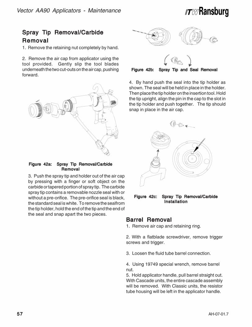
AH-07-01.7
Vector AA90 Applicators - Maintenance
5757575757
Spray TSpray TSpray TSpray TSpray Tip Removal/Carbideip Removal/Carbideip Removal/Carbideip Removal/Carbideip Removal/CarbideRemovalRemovalRemovalRemovalRemoval1. Remove the retaining nut completely by hand.
2. Remove the air cap from applicator using thetool provided. Gently slip the tool bladesunderneath the two cut-outs on the air cap, pushingforward.
Figure 42a: Spray Tip Removal/CarbideFigure 42a: Spray Tip Removal/CarbideFigure 42a: Spray Tip Removal/CarbideFigure 42a: Spray Tip Removal/CarbideFigure 42a: Spray Tip Removal/CarbideRemovalRemovalRemovalRemovalRemoval
Figure 42b: Spray Tip and Seal RemovalFigure 42b: Spray Tip and Seal RemovalFigure 42b: Spray Tip and Seal RemovalFigure 42b: Spray Tip and Seal RemovalFigure 42b: Spray Tip and Seal Removal
Figure 42c: Spray Tip Removal/CarbideFigure 42c: Spray Tip Removal/CarbideFigure 42c: Spray Tip Removal/CarbideFigure 42c: Spray Tip Removal/CarbideFigure 42c: Spray Tip Removal/CarbideInstallationInstallationInstallationInstallationInstallation
Barrel RemovalBarrel RemovalBarrel RemovalBarrel RemovalBarrel Removal1. Remove air cap and retaining ring.
2. With a flatblade screwdriver, remove triggerscrews and trigger.
3. Loosen the fluid tube barrel connection.
4. Using 19749 special wrench, remove barrelnut.5. Hold applicator handle, pull barrel straight out.With Cascade units, the entire cascade assemblywill be removed. With Classic units, the resistortube housing will be left in the applicator handle.
3. Push the spray tip and holder out of the air capby pressing with a finger or soft object on thecarbide or tapered portion of spray tip. The carbidespray tip contains a removable nozzle seal with orwithout a pre-orifice. The pre-orifice seal is black,the standard seal is white. To remove the sealfromthe tip holder, hold the end of the tip and the end ofthe seal and snap apart the two pieces.
4. By hand push the seal into the tip holder asshown. The seal will be held in place in the holder.Then place the tip holder on the insertion tool. Holdthe tip upright, align the pin in the cap to the slot inthe tip holder and push together. The tip shouldsnap in place in the air cap.

AH-07-01.7
Vector AA90 Applicators - Maintenance
5858585858
Figure 43: Barrel RemovalFigure 43: Barrel RemovalFigure 43: Barrel RemovalFigure 43: Barrel RemovalFigure 43: Barrel Removal
Barrel DisassemblyBarrel DisassemblyBarrel DisassemblyBarrel DisassemblyBarrel Disassembly1. Using 76428 wrench, remove nozzle.
Figure 44a: Barrel DisassemblyFigure 44a: Barrel DisassemblyFigure 44a: Barrel DisassemblyFigure 44a: Barrel DisassemblyFigure 44a: Barrel Disassembly
Figure 44b: Barrel DisassemblyFigure 44b: Barrel DisassemblyFigure 44b: Barrel DisassemblyFigure 44b: Barrel DisassemblyFigure 44b: Barrel Disassembly
Needle Shaft PackingNeedle Shaft PackingNeedle Shaft PackingNeedle Shaft PackingNeedle Shaft PackingReplacementReplacementReplacementReplacementReplacement1. Remove spring spray retainer and lock nut fromshaft. Pull all rear seal parts off shaft. Replacecomponents as required.
Figure 45a: Needle Shaft PackingFigure 45a: Needle Shaft PackingFigure 45a: Needle Shaft PackingFigure 45a: Needle Shaft PackingFigure 45a: Needle Shaft PackingReplacementReplacementReplacementReplacementReplacement
2. Using 19749 special tool, remove packing nut.
3. Pull needle shaft assembly straight out.

AH-07-01.7
Vector AA90 Applicators - Maintenance
5959595959
Reinstall SpringReinstall SpringReinstall SpringReinstall SpringReinstall Spring
Figure 46b: Needle Shaft PackingFigure 46b: Needle Shaft PackingFigure 46b: Needle Shaft PackingFigure 46b: Needle Shaft PackingFigure 46b: Needle Shaft PackingReassemblyReassemblyReassemblyReassemblyReassembly
3. Remove front spreader seal, front u-cup seal,rear spreader seal, rear u-cup seal, and pusherseal.
Figure 45c: Needle Shaft PackingFigure 45c: Needle Shaft PackingFigure 45c: Needle Shaft PackingFigure 45c: Needle Shaft PackingFigure 45c: Needle Shaft PackingReplacementReplacementReplacementReplacementReplacement
Needle Shaft Pack ReassemblyNeedle Shaft Pack ReassemblyNeedle Shaft Pack ReassemblyNeedle Shaft Pack ReassemblyNeedle Shaft Pack Reassembly1. Install pusher seal, rear u-cup, rear spreaderseal, front u-cup seal, front spreader seal asshown. Orient seals per Figure 52a.
2. Install jam nut all the way on the shaft. Install thecarbide ball all the way down using two 74133tools. Tighten the jam nut against the carbide ball.
3. Install rest of parts in reverse order. Ensure allparts are adequately coated with LSCH0009-00grease. Hand tighten needle shaft spring retainerand locking nut.
Figure 47: Reinstall SpringFigure 47: Reinstall SpringFigure 47: Reinstall SpringFigure 47: Reinstall SpringFigure 47: Reinstall Spring
Figure 46a: Needle Shaft Pack ReassemblyFigure 46a: Needle Shaft Pack ReassemblyFigure 46a: Needle Shaft Pack ReassemblyFigure 46a: Needle Shaft Pack ReassemblyFigure 46a: Needle Shaft Pack Reassembly
2. Using two 74133 tools, remove carbide ball andjam nut. Remove packing components.
Figure 45b: Needle Shaft PackingFigure 45b: Needle Shaft PackingFigure 45b: Needle Shaft PackingFigure 45b: Needle Shaft PackingFigure 45b: Needle Shaft PackingReplacementReplacementReplacementReplacementReplacement

AH-07-01.7
Vector AA90 Applicators - Maintenance
6060606060
Rebuild BarrelRebuild BarrelRebuild BarrelRebuild BarrelRebuild Barrel1. Install tip and seals into barrel.
Figure 48a: Rebuilding BarrelFigure 48a: Rebuilding BarrelFigure 48a: Rebuilding BarrelFigure 48a: Rebuilding BarrelFigure 48a: Rebuilding Barrel
2. Install a generous amount of LSCH0009-00 intoneedle shaft cavity. Install needle shaft assemblyinto barrel
Figure 48b: Rebuilding BarrelFigure 48b: Rebuilding BarrelFigure 48b: Rebuilding BarrelFigure 48b: Rebuilding BarrelFigure 48b: Rebuilding Barrel
3. Tighten packing nut until resistance on the shaftmay be felt when the shaft is pushed in and out.
Figure 48c: Rebuilding BarrelFigure 48c: Rebuilding BarrelFigure 48c: Rebuilding BarrelFigure 48c: Rebuilding BarrelFigure 48c: Rebuilding Barrel
Install Barrel on HandleInstall Barrel on HandleInstall Barrel on HandleInstall Barrel on HandleInstall Barrel on Handle1. Adjust spring retainer and locking nut todimension shown. Tighten against each other.
2. Push barrel straight into handle.
3. Using 19749 wrench, tighten barrel nut ontohandle
4. Tighten fluid tube nut into place.
5. Install trigger and trigger screws.
Figure 49a: Install Barrel on HandleFigure 49a: Install Barrel on HandleFigure 49a: Install Barrel on HandleFigure 49a: Install Barrel on HandleFigure 49a: Install Barrel on Handle

AH-07-01.7
Vector AA90 Applicators - Maintenance
6161616161
4. Remove trigger lock assembly.
Figure 50c: Handle DisassemblyFigure 50c: Handle DisassemblyFigure 50c: Handle DisassemblyFigure 50c: Handle DisassemblyFigure 50c: Handle Disassembly
5. Remove air fitting and bracket.
Handle DisassemblyHandle DisassemblyHandle DisassemblyHandle DisassemblyHandle Disassembly1. Remove the barrel.
2. Remove the fluid tube from the bracket.
3. Remove the fan valve and rear cover.
Figure 49b: Install Barrel on HandleFigure 49b: Install Barrel on HandleFigure 49b: Install Barrel on HandleFigure 49b: Install Barrel on HandleFigure 49b: Install Barrel on Handle
Figure 50a: Handle DisassemblyFigure 50a: Handle DisassemblyFigure 50a: Handle DisassemblyFigure 50a: Handle DisassemblyFigure 50a: Handle Disassembly
Figure 50b: Handle DisassemblyFigure 50b: Handle DisassemblyFigure 50b: Handle DisassemblyFigure 50b: Handle DisassemblyFigure 50b: Handle Disassembly

AH-07-01.7
Vector AA90 Applicators - Maintenance
6262626262
6. Remove air valve and air valve seal.
Figure 50e: Handle DisassemblyFigure 50e: Handle DisassemblyFigure 50e: Handle DisassemblyFigure 50e: Handle DisassemblyFigure 50e: Handle Disassembly
7. Remove gasket, hook, and hook gasket.
Figure 50f: Handle DisassemblyFigure 50f: Handle DisassemblyFigure 50f: Handle DisassemblyFigure 50f: Handle DisassemblyFigure 50f: Handle Disassembly
8. For Cascade Units - remove plug assembly.
Figure 50g: Handle DisassemblyFigure 50g: Handle DisassemblyFigure 50g: Handle DisassemblyFigure 50g: Handle DisassemblyFigure 50g: Handle Disassembly
9. For Classic Units - remove resistor tubeassembly.
Apply LSCH0009-00 dielectric grease to resistortube prior to reassembly.
Figure 50h: Handle DisassemblyFigure 50h: Handle DisassemblyFigure 50h: Handle DisassemblyFigure 50h: Handle DisassemblyFigure 50h: Handle Disassembly
Handle ReassemblyHandle ReassemblyHandle ReassemblyHandle ReassemblyHandle Reassembly1. Reverse disassembly procedure. Replaceparts as required. Use LSCH0009-00 on allelectrical components.
Figure 50d: Handle DisassemblyFigure 50d: Handle DisassemblyFigure 50d: Handle DisassemblyFigure 50d: Handle DisassemblyFigure 50d: Handle Disassembly
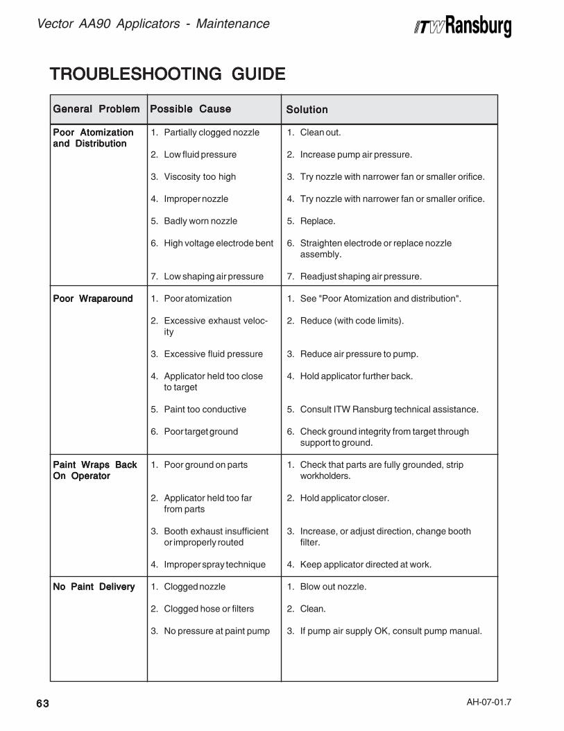
AH-07-01.7
TROUBLESHOOTING GUIDETROUBLESHOOTING GUIDETROUBLESHOOTING GUIDETROUBLESHOOTING GUIDETROUBLESHOOTING GUIDE
Vector AA90 Applicators - Maintenance
6363636363
General ProblemGeneral ProblemGeneral ProblemGeneral ProblemGeneral Problem Possible CausePossible CausePossible CausePossible CausePossible Cause SolutionSolutionSolutionSolutionSolution
Poor AtomizationPoor AtomizationPoor AtomizationPoor AtomizationPoor Atomizationand Distributionand Distributionand Distributionand Distributionand Distribution
Poor WraparoundPoor WraparoundPoor WraparoundPoor WraparoundPoor Wraparound
Paint Wraps BackPaint Wraps BackPaint Wraps BackPaint Wraps BackPaint Wraps BackOn OperatorOn OperatorOn OperatorOn OperatorOn Operator
No Paint DeliveryNo Paint DeliveryNo Paint DeliveryNo Paint DeliveryNo Paint Delivery
1. Partially clogged nozzle
2. Low fluid pressure
3. Viscosity too high
4. Improper nozzle
5. Badly worn nozzle
6. High voltage electrode bent
7. Low shaping air pressure
1. Poor atomization
2. Excessive exhaust veloc-ity
3. Excessive fluid pressure
4. Applicator held too closeto target
5. Paint too conductive
6. Poor target ground
1. Poor ground on parts
2. Applicator held too farfrom parts
3. Booth exhaust insufficientor improperly routed
4. Improper spray technique
1. Clogged nozzle
2. Clogged hose or filters
3. No pressure at paint pump
1. Clean out.
2. Increase pump air pressure.
3. Try nozzle with narrower fan or smaller orifice.
4. Try nozzle with narrower fan or smaller orifice.
5. Replace.
6. Straighten electrode or replace nozzleassembly.
7. Readjust shaping air pressure.
1. See "Poor Atomization and distribution".
2. Reduce (with code limits).
3. Reduce air pressure to pump.
4. Hold applicator further back.
5. Consult ITW Ransburg technical assistance.
6. Check ground integrity from target throughsupport to ground.
1. Check that parts are fully grounded, stripworkholders.
2. Hold applicator closer.
3. Increase, or adjust direction, change boothfilter.
4. Keep applicator directed at work.
1. Blow out nozzle.
2. Clean.
3. If pump air supply OK, consult pump manual.

AH-07-01.7
Vector AA90 Applicators - Maintenance
6464646464
General ProblemGeneral ProblemGeneral ProblemGeneral ProblemGeneral Problem Possible CausePossible CausePossible CausePossible CausePossible Cause SolutionSolutionSolutionSolutionSolution
Excessive SurgingExcessive SurgingExcessive SurgingExcessive SurgingExcessive Surging
Persistent NozzlePersistent NozzlePersistent NozzlePersistent NozzlePersistent NozzleCloggingCloggingCloggingCloggingClogging
Paint LeaksPaint LeaksPaint LeaksPaint LeaksPaint LeaksThrough Center ofThrough Center ofThrough Center ofThrough Center ofThrough Center ofNozzleNozzleNozzleNozzleNozzle(Failure to Shut Off)
Paint Leaks AroundPaint Leaks AroundPaint Leaks AroundPaint Leaks AroundPaint Leaks Aroundthe Nozzle Capthe Nozzle Capthe Nozzle Capthe Nozzle Capthe Nozzle Cap
Paint Leaks AtPaint Leaks AtPaint Leaks AtPaint Leaks AtPaint Leaks AtRear of BarrelRear of BarrelRear of BarrelRear of BarrelRear of Barrel
Orange Peel orOrange Peel orOrange Peel orOrange Peel orOrange Peel orRough FinishRough FinishRough FinishRough FinishRough Finish
Paint Runs or HasPaint Runs or HasPaint Runs or HasPaint Runs or HasPaint Runs or HasPoor HidingPoor HidingPoor HidingPoor HidingPoor HidingQualitiesQualitiesQualitiesQualitiesQualities
1. Restriction in pump air line
2. Insufficient pump capacity
3. Clogged paint filter
4. Low air volume capacity
5. Nozzle too large
1. Paint allowed to dry innozzle or line
2. Paint applicator filter toocoarse or damaged
3. Paint pigments too coarse
1. Loose nozzle cap
2. Improper trigger adjustment
3. Defective or dirty valve seat
1. Loose nozzle cap
2. Fluid seal worn
1. Loose packing nut
1. Evaporation rate too fast
2. Poor atomization
3. Viscosity too high
1. Low solids paint
2. Low viscosity
3. Excessive delivery
1. Remove restriction.
2. Secure larger pump or reduce output.
3. Service or replace.
4. Check factory air capacity.
5. Replace with correct nozzle.
1. Flush lines with solvent after each use.
2. Replace or change to finer screen paint filter.
3. Pre-filter paint and/or use larger nozzle orifice.
1. Tighten nut.
2. Readjust.
3. Flush out or replace as needed.
1. Tighten nut.
2. Replace seal.
1. Tighten packing nut.
1. Use slower evaporating solvent.
2. See "Poor Atomization and Distribution".
3. Add solvent or heat.
1. Use less solvent.
2. Use less solvent.
3. Use smaller nozzle, wider fan angle, lowerpump pressure.
(Continued On Next Page)
TROUBLESHOOTING GUIDE (Cont.)TROUBLESHOOTING GUIDE (Cont.)TROUBLESHOOTING GUIDE (Cont.)TROUBLESHOOTING GUIDE (Cont.)TROUBLESHOOTING GUIDE (Cont.)
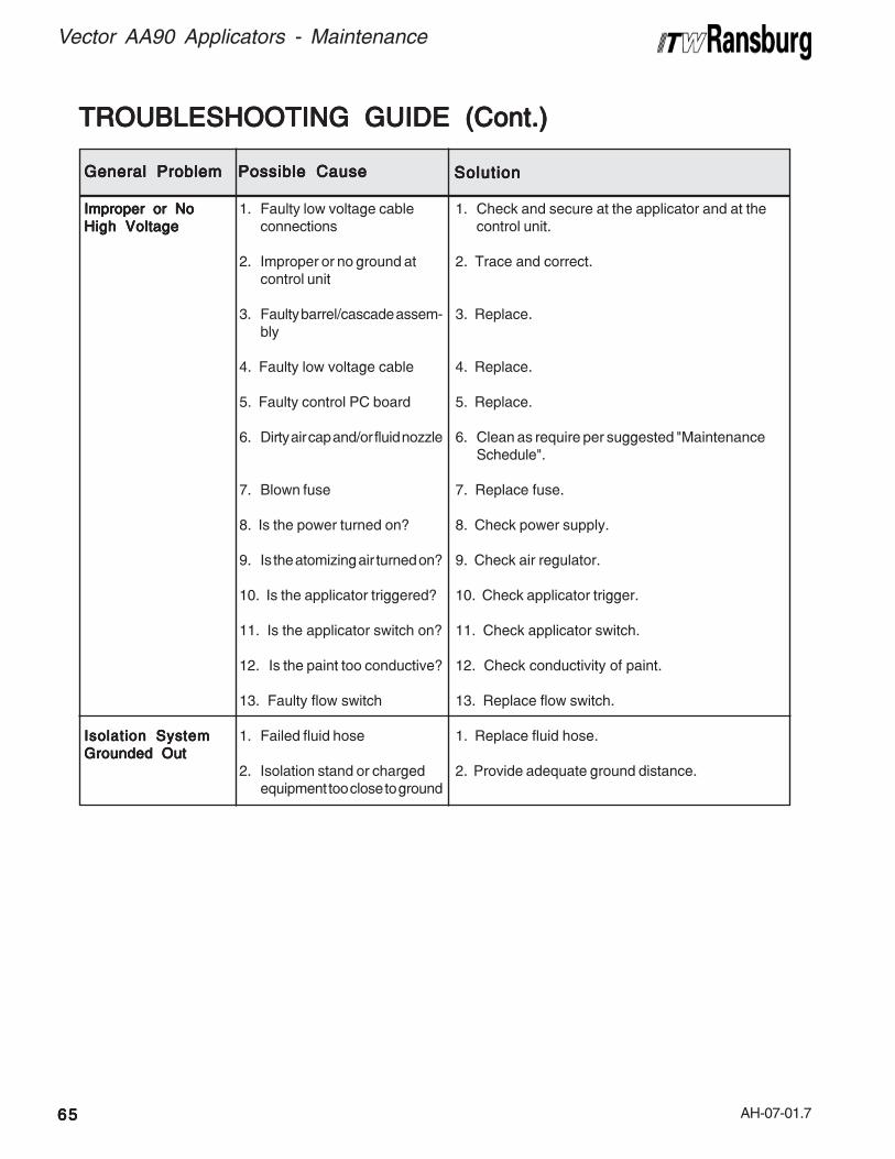
AH-07-01.7
TROUBLESHOOTING GUIDE (Cont.)TROUBLESHOOTING GUIDE (Cont.)TROUBLESHOOTING GUIDE (Cont.)TROUBLESHOOTING GUIDE (Cont.)TROUBLESHOOTING GUIDE (Cont.)
General ProblemGeneral ProblemGeneral ProblemGeneral ProblemGeneral Problem Possible CausePossible CausePossible CausePossible CausePossible Cause SolutionSolutionSolutionSolutionSolution
Improper or NoImproper or NoImproper or NoImproper or NoImproper or NoHigh VoltageHigh VoltageHigh VoltageHigh VoltageHigh Voltage
Isolation SystemIsolation SystemIsolation SystemIsolation SystemIsolation SystemGrounded OutGrounded OutGrounded OutGrounded OutGrounded Out
1. Faulty low voltage cableconnections
2. Improper or no ground atcontrol unit
3. Faulty barrel/cascade assem-bly
4. Faulty low voltage cable
5. Faulty control PC board
6. Dirty air cap and/or fluid nozzle
7. Blown fuse
8. Is the power turned on?
9. Is the atomizing air turned on?
10. Is the applicator triggered?
11. Is the applicator switch on?
12. Is the paint too conductive?
13. Faulty flow switch
1. Failed fluid hose
2. Isolation stand or chargedequipment too close to ground
1. Check and secure at the applicator and at thecontrol unit.
2. Trace and correct.
3. Replace.
4. Replace.
5. Replace.
6. Clean as require per suggested "MaintenanceSchedule".
7. Replace fuse.
8. Check power supply.
9. Check air regulator.
10. Check applicator trigger.
11. Check applicator switch.
12. Check conductivity of paint.
13. Replace flow switch.
1. Replace fluid hose.
2. Provide adequate ground distance.
Vector AA90 Applicators - Maintenance
6565656565

AH-07-01.7
Vector AA90 Applicators - Maintenance
6666666666
NOTESNOTESNOTESNOTESNOTES
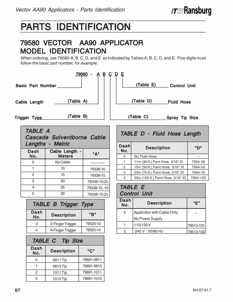
AH-07-01.7
Vector AA90 Applicators - Parts Identification
6767676767
PPPPPARARARARARTS IDENTIFICATS IDENTIFICATS IDENTIFICATS IDENTIFICATS IDENTIFICATIONTIONTIONTIONTION
Fluid HoseFluid HoseFluid HoseFluid HoseFluid Hose
When ordering, use 79580-A, B, C, D, and E as indicated by Tables A, B, C, D, and E. Five digits mustfollow the basic part number, for example:
79580 - A B C D E 79580 - A B C D E 79580 - A B C D E 79580 - A B C D E 79580 - A B C D E
Cable LengthCable LengthCable LengthCable LengthCable Length
Basic Part NumberBasic Part NumberBasic Part NumberBasic Part NumberBasic Part Number
Trigger TypeTrigger TypeTrigger TypeTrigger TypeTrigger Type Spray Tip SizeSpray Tip SizeSpray Tip SizeSpray Tip SizeSpray Tip Size
(Table A)(Table A)(Table A)(Table A)(Table A)
(Table B)(Table B)(Table B)(Table B)(Table B) (Table C)(Table C)(Table C)(Table C)(Table C)
79580 VECT79580 VECT79580 VECT79580 VECT79580 VECTOR AA90 APPLICAOR AA90 APPLICAOR AA90 APPLICAOR AA90 APPLICAOR AA90 APPLICATTTTTORORORORORMODELMODELMODELMODELMODEL IDENTIFICA IDENTIFICA IDENTIFICA IDENTIFICA IDENTIFICATIONTIONTIONTIONTION
(Table D)(Table D)(Table D)(Table D)(Table D)
Control UnitControl UnitControl UnitControl UnitControl Unit(Table E)(Table E)(Table E)(Table E)(Table E)
No Cable
10
15
20
25
30
TTTTTABLE AABLE AABLE AABLE AABLE ACascade Solventborne CableCascade Solventborne CableCascade Solventborne CableCascade Solventborne CableCascade Solventborne CableLengths - MetricLengths - MetricLengths - MetricLengths - MetricLengths - Metric
------------
79338-10
79338-15
79338-10 (2)
79338-15,-10
79338-15 (2)
"A""A""A""A""A"Cable Length -Cable Length -Cable Length -Cable Length -Cable Length -
MetersMetersMetersMetersMeters0
1
2
3
4
5
DashDashDashDashDashNo.No.No.No.No.
2-Finger Trigger
4-Finger Trigger
79325-12
79325-14
DescriptionDescriptionDescriptionDescriptionDescription
2
4
DashDashDashDashDashNo.No.No.No.No.
TTTTTABLE B TABLE B TABLE B TABLE B TABLE B Trigger Trigger Trigger Trigger Trigger Typeypeypeypeype
"B""B""B""B""B"
0811 Tip
0813 Tip
1011 Tip
1015 Tip
79691-0811
79691-0813
79691-1011
79691-1015
DescriptionDescriptionDescriptionDescriptionDescription
0
1
2
3
DashDashDashDashDashNo.No.No.No.No.
TTTTTABLE C TABLE C TABLE C TABLE C TABLE C Tip Sizeip Sizeip Sizeip Sizeip Size
"C""C""C""C""C"
Applicator with Cable Only,
No Power Supply
110/120 V
240 V - 50/60 Hz
--
79513-131
79513-132
"E""E""E""E""E"DescriptionDescriptionDescriptionDescriptionDescription
0
1
2
DashDashDashDashDashNo.No.No.No.No.
TTTTTABLE EABLE EABLE EABLE EABLE EControl UnitControl UnitControl UnitControl UnitControl Unit
No Fluid Hose
11m (36-ft.) Pant Hose, 3/16" ID
15m (50-ft.) Paint Hose, 3/16" ID
23m (75-ft.) Paint Hose, 3/16" ID
30m (100-ft.) Paint Hose, 3/16" ID
TTTTTABLE D - Fluid Hose LengthABLE D - Fluid Hose LengthABLE D - Fluid Hose LengthABLE D - Fluid Hose LengthABLE D - Fluid Hose Length
0
1
2
3
4
--
7994-36
7994-50
7994-75
7994-100
DashDashDashDashDashNo.No.No.No.No.
"D""D""D""D""D"DescriptionDescriptionDescriptionDescriptionDescription

AH-07-01.7
Vector AA90 Applicators - Parts Identification
6868686868
PPPPPARARARARARTS IDENTIFICATS IDENTIFICATS IDENTIFICATS IDENTIFICATS IDENTIFICATIONTIONTIONTIONTION
Fluid HoseFluid HoseFluid HoseFluid HoseFluid Hose
When ordering, use 79581-A, B, C, D, and E as indicated by Tables A, B, C, D, and E. Five digits mustfollow the basic part number, for example:
79581 - A B C D E 79581 - A B C D E 79581 - A B C D E 79581 - A B C D E 79581 - A B C D E
Cable LengthCable LengthCable LengthCable LengthCable Length
Basic Part NumberBasic Part NumberBasic Part NumberBasic Part NumberBasic Part Number
Trigger TypeTrigger TypeTrigger TypeTrigger TypeTrigger Type Spray Tip SizeSpray Tip SizeSpray Tip SizeSpray Tip SizeSpray Tip Size
(Table F)(Table F)(Table F)(Table F)(Table F)
(Table G)(Table G)(Table G)(Table G)(Table G) (Table H)(Table H)(Table H)(Table H)(Table H)
79581 VECT79581 VECT79581 VECT79581 VECT79581 VECTOR AA90 APPLICAOR AA90 APPLICAOR AA90 APPLICAOR AA90 APPLICAOR AA90 APPLICATTTTTORORORORORMODELMODELMODELMODELMODEL IDENTIFICA IDENTIFICA IDENTIFICA IDENTIFICA IDENTIFICATIONTIONTIONTIONTION
(Table J)(Table J)(Table J)(Table J)(Table J)
Control UnitControl UnitControl UnitControl UnitControl Unit(Table K)(Table K)(Table K)(Table K)(Table K)
No Fluid Hose
11m (36-ft.) Pant Hose, 3/16" ID
15m (50-ft.) Paint Hose, 3/16" ID
23m (75-ft.) Paint Hose, 3/16" ID
30m (100-ft.) Paint Hose, 3/16" ID
TTTTTABLE J - Fluid Hose LengthABLE J - Fluid Hose LengthABLE J - Fluid Hose LengthABLE J - Fluid Hose LengthABLE J - Fluid Hose Length
0
1
2
3
4
--
7994-36
7994-50
7994-75
7994-100
DashDashDashDashDashNo.No.No.No.No.
"J""J""J""J""J"DescriptionDescriptionDescriptionDescriptionDescription
--
79344-141
79344-142
"K""K""K""K""K"
Applicator with Cable Only,
No Power Supply
110/120 V
240 V - 50/60 Hz
DescriptionDescriptionDescriptionDescriptionDescription
0
1
2
DashDashDashDashDashNo.No.No.No.No.
TTTTTABLE KABLE KABLE KABLE KABLE KControl UnitControl UnitControl UnitControl UnitControl Unit
0811 Tip
0813 Tip
1011 Tip
1015 Tip
79691-0811
79691-0813
79691-1011
79691-1015
DescriptionDescriptionDescriptionDescriptionDescription
0
1
2
3
DashDashDashDashDashNo.No.No.No.No.
TTTTTABLE H TABLE H TABLE H TABLE H TABLE H Tip Sizeip Sizeip Sizeip Sizeip Size
"H""H""H""H""H"
2-Finger Trigger
4-Finger Trigger
79325-12
79325-14
DescriptionDescriptionDescriptionDescriptionDescription
2
4
DashDashDashDashDashNo.No.No.No.No.
TTTTTABLE G TABLE G TABLE G TABLE G TABLE G Trigger Trigger Trigger Trigger Trigger Typeypeypeypeype
"G""G""G""G""G"
No Cable
10
15
20
25
30
TTTTTABLE FABLE FABLE FABLE FABLE FCascade Solventborne CableCascade Solventborne CableCascade Solventborne CableCascade Solventborne CableCascade Solventborne CableLengths - MetricLengths - MetricLengths - MetricLengths - MetricLengths - Metric
------------
79549-10
79519-15
79519-20
79519-25
79519-30
"F""F""F""F""F"Cable Length -Cable Length -Cable Length -Cable Length -Cable Length -
MetersMetersMetersMetersMeters
0
1
2
3
4
5
DashDashDashDashDashNo.No.No.No.No.

AH-07-01.7
Vector AA90 Applicators - Parts Identification
6969696969
Figure 51: Vector AA90 Cascade Exploded ViewFigure 51: Vector AA90 Cascade Exploded ViewFigure 51: Vector AA90 Cascade Exploded ViewFigure 51: Vector AA90 Cascade Exploded ViewFigure 51: Vector AA90 Cascade Exploded View
41
42
44
2
1819
20
2122
26
2728
2930
3135
36
33
3738
19
4
3
5
3940
7
6
8
10
1113
14
1516
17
2
12
32
23

AH-07-01.7
Vector AA90 Applicators - Parts Identification
7070707070
1 79568-00 Ring, Retaining, Air Assist 12 19603-8F Set Screw, Cup Point 23 79460-04 Assembly, Plug, Low Voltage 14 79588-00 Assembly, Barrel AA90 With Needle, Retaining Ring 1
79586-00 Assembly, Barrel AA90, Barrel Only 15 76105-00 Swivel, High Pressure 16 77096-00 Fluid Tube Assembly 17 79476-01 Handle Assembly 18 7720-01 Filter, Paint, .005 Web Spacing, 100 Mesh (Fine) 1
7720-02 Filter, Paint, .009 Web Spacing, 60 Mesh (Course) 19 LSOR0005-17 O-Ring, Teflon Encapsulated 110 72375-02 Seal, Teflon 111 17130-00 Spring, Return 112 79001-31 O-Ring, Solvent Proof 113 79310-00 Rod Assembly, Dual Stage Air Valve 114 79453-00 Cap, Retaining, Air Valve 115 78635-00 Nut, Retaining, Air Valve 116 10051-05 Cup Seal, Spring Loaded 117 79322-11 Hook, Blank, Molded 118 79570-00 Bracket, Support, Offset 119 74189-00 Fitting, Air Inlet (REM) 120 79001-08 O-Ring, Solvent Proof 121 Table B - "B"Table B - "B"Table B - "B"Table B - "B"Table B - "B" Trigger, Molded 122 79454-00 Screw, Trigger Retention 223 79638-00 Trigger Lock Assembly 124 ---- ---- --25 ---- ---- --26 8301-08C SHCS 127 79566-10 Assembly, Valve, Fan Click Adjust 128 79322-00 Hook, Molded 129 79479-00 O-Ring, Cord 130 79471-01 Assembly, Rear Cover 131 79378-00 Gasket, Barrel Cover 132 78824-00 Spring 133 78632-00 Nut, Locking, Needle Shaft 134 78633-00 Spring Retainer, Needle Shaft 135 79373-00 Nut, Retaining Barrel 136 75326-00 Ring, Retaining 137 79668-00 Assembly, Valve Seat Body 138 72375-03 Seal, Teflon 139 79695-00 Assembly, Air Cap, Air Assist 140 Table C - "C"Table C - "C"Table C - "C"Table C - "C"Table C - "C" Carbide Tip Assemblies 141 Table A - "A"Table A - "A"Table A - "A"Table A - "A"Table A - "A" Cable, Low Voltage Table A - "A"Table A - "A"Table A - "A"Table A - "A"Table A - "A"42 79692-00-K3 Seal, Carbide Tip, Kit of 3 143 -- -- --44 LSOR0005-11 O-Ring, Teflon Encapsulated (included in item 39) 1
Item #Item #Item #Item #Item # Part #Part #Part #Part #Part # DescriptionDescriptionDescriptionDescriptionDescription Q t yQ t yQ t yQ t yQ t y
VECTVECTVECTVECTVECTOR AA90 CASCADE - POR AA90 CASCADE - POR AA90 CASCADE - POR AA90 CASCADE - POR AA90 CASCADE - PARARARARARTS LISTTS LISTTS LISTTS LISTTS LIST (Figure 51) (Figure 51) (Figure 51) (Figure 51) (Figure 51)

AH-07-01.7
Figure 52: Vector AA90 Classic Exploded ViewFigure 52: Vector AA90 Classic Exploded ViewFigure 52: Vector AA90 Classic Exploded ViewFigure 52: Vector AA90 Classic Exploded ViewFigure 52: Vector AA90 Classic Exploded View
Vector AA90 Applicators - Parts Identification
7171717171
45
472
9 38
414
26
39
44
43
4142
40
37
36
15
10
253021
16
3
5
7
8
17
18
3983
23
27
24
1
22
19
3533
34
32 31
28
29
20
6
11

AH-07-01.7
Vector AA90 Applicators - Parts Identification
7272727272
1 79476-01 Handle Assembly 12 79568-00 Ring, Retaining, Air Assist 13 19603-8F Set Screw, Cup Point 24 77096-00 Fluid Tube Assembly, 15 76105-00 Swivel, High Pressure 16 79584-00 Assembly, Barrel, AA90 Classic With Needle, 1
Retaining Ring and Resistor Tube79583-00 Assembly Barrel, Barrel Only 1
7 7720-01 Filter, Paint, .005 Web Spacing, 100 Mesh (Fine) 17720-02 Filter, Paint, .009 Web Spacing, 60 Mesh (Course) 1
8 Table F - "F"Table F - "F"Table F - "F"Table F - "F"Table F - "F" Assembly, Cable High Voltage 19 LSOR0005-17 O-Ring, Teflon Encapsulated 110 72375-02 Seal, Teflon 111 79322-11 Hook, Blank, Molded 112 ---- ---- --13 ---- ---- --14 79638-00 Trigger Lock Assembly 115 Table G - "G"Table G - "G"Table G - "G"Table G - "G"Table G - "G" Trigger, Molded, 2-Finger 116 79454-00 Screw, Trigger Retention 217 79570-00 Bracket, Support, Offset 118 74189-00 Fitting,Air Inlet (REM) 119 79566-10 Assembly, Valve, Fan Click Adjust 120 79322-00 Hook, Molded 121 78635-00 Nut, Retaining, Air Valve 122 79310-00 Rod Assembly, Dual Stage Air Valve 123 79471-11 Assembly, Rear Housing, AA90 Classic 124 79453-00 Cap, Retaining, Air Valve 125 8301-08C SHCS 126 17130-00 Spring, Return 127 79001-31 O-Ring, Solvent Proof 128 79378-00 Gasket, Barrel Cover 129 79479-00 O-Ring, Cord 130 10051-05 Cup Seal, Spring Loaded 131 75326-00 Ring, Retaining 132 79373-00 Nut, Retaining Barrel 133 78633-00 Spring Retainer, Needle Shaft 134 78623-00 Nut, Locking, Needle Shaft 135 78824-00 Spring 136 79668-00 Assembly, Valve Seat Body 137 72375-03 Seal, Teflon 138 79695-00 Assembly, Air Cap 139 79001-08 O-Ring, Solvent Proof 240 Table H - "H"Table H - "H"Table H - "H"Table H - "H"Table H - "H" Carbide Tip Assemblies 141 70397-02 Resistor Housing, Potted 142 14061-05 Sponge, Conductive 143 79001-07 O-Ring, Solvent Proof 144 14061-08 Sponge, Conductive 145 79692-00-K3 Seal, Carbide Tip, Kit of 3 146 -- -- --47 LSOR0005-11 O-Ring, Teflon Encapsulated (included in item 38) 1
Item #Item #Item #Item #Item # Part #Part #Part #Part #Part # DescriptionDescriptionDescriptionDescriptionDescription Q t yQ t yQ t yQ t yQ t y
VECTVECTVECTVECTVECTOR AA90 CLASSIC - POR AA90 CLASSIC - POR AA90 CLASSIC - POR AA90 CLASSIC - POR AA90 CLASSIC - PARARARARARTS LISTTS LISTTS LISTTS LISTTS LIST (Figure 52) (Figure 52) (Figure 52) (Figure 52) (Figure 52)

AH-07-01.7
Vector AA90 Applicators - Parts Identification
7373737373
Figure 53: AccessoriesFigure 53: AccessoriesFigure 53: AccessoriesFigure 53: AccessoriesFigure 53: Accessories
* The "Accessories" are included with each Classic or Cascade Unit
1 79676-00 Wrench, Nozzle Removal 12 74133-00 Wrench, Needle 23 76104-00 High Pressure Whip Hose, 1m 14 19749-00 Wrench Assembly 15 71880-06 Nipple, Male Double 16 79529-00 Disposable Applicator Cover 1
79529-00-K5 Disposable Applicator Cover (Lots of 5) --7 74187-02 Air Hose Assembly, 2m Whip (6.5 ft.) 18 77105-00 Adapter, 3/8" AN Male to 1/4" NPSM(M) 19 79338-01 1 Meter Low Voltage Cable (79580 Vector Cascade Only) 110 79634-00-K3 Carbide Tip Seals, Kit of 3 1
79634-XX Carbide Tip Pre-Orifice 111 79642-00 Cap Removal Tool 1
Item #Item #Item #Item #Item # Part #Part #Part #Part #Part # DescriptionDescriptionDescriptionDescriptionDescription Q t yQ t yQ t yQ t yQ t y
ACCESSORIES - PACCESSORIES - PACCESSORIES - PACCESSORIES - PACCESSORIES - PARARARARARTS LISTTS LISTTS LISTTS LISTTS LIST (Figure 53) * (Figure 53) * (Figure 53) * (Figure 53) * (Figure 53) *
11
2
5
14
8
3
97
610

AH-07-01.7
Vector AA90 Applicators - Parts Identification
7474747474
Figure 54: 7994-XX Fluid LineFigure 54: 7994-XX Fluid LineFigure 54: 7994-XX Fluid LineFigure 54: 7994-XX Fluid LineFigure 54: 7994-XX Fluid Line
7994-XX FLUID LINE7994-XX FLUID LINE7994-XX FLUID LINE7994-XX FLUID LINE7994-XX FLUID LINE(Figure 54)(Figure 54)(Figure 54)(Figure 54)(Figure 54)
Part Number Part Number Part Number Part Number Part Number Length Length Length Length Length
Feet Meters Feet Meters Feet Meters Feet Meters Feet Meters7994-36 36' ± 9" 11 ± .237994-50 50' ± 12" 15 ± .307994-75 75' ± 18" 23 ± .467994-100 100' ± 24" 30 ± .61
Figure 55: 79575-00 AA90 Needle ShaftFigure 55: 79575-00 AA90 Needle ShaftFigure 55: 79575-00 AA90 Needle ShaftFigure 55: 79575-00 AA90 Needle ShaftFigure 55: 79575-00 AA90 Needle Shaft
1 79618-00 Spreader, Seal, Front 12 73345-00 Seal, Front U-Cup 13 72378-01 Packing Tube 14 73347-00 Container, Rear Seal 15 74330-00 Seal, High Pressure 16 73348-00 Retainer, Real Seal 17 72209-05 O-Ring, Metric 18 73354-00 Nut, Packing 19 79572-00 Assembly, Needle Shaft 110 73351-00 Nut, Jam 111 73350-00 Assembly, Ball Valve 112 79615-00 Spreader, Seal Rear 113 79616-00 Seal, Rear U-Cup 114 79617-00 Seal, Pusher, AA90 1
Item #Item #Item #Item #Item # Part #Part #Part #Part #Part # DescriptionDescriptionDescriptionDescriptionDescription Q t yQ t yQ t yQ t yQ t y
79575-00 AA90 NEEDLE SHAFT79575-00 AA90 NEEDLE SHAFT79575-00 AA90 NEEDLE SHAFT79575-00 AA90 NEEDLE SHAFT79575-00 AA90 NEEDLE SHAFT - P - P - P - P - PARARARARARTS LISTTS LISTTS LISTTS LISTTS LIST (Figure 55) (Figure 55) (Figure 55) (Figure 55) (Figure 55)
7 5
8
6
4
3
9
14
13
12
2
11
10
1

AH-07-01.7
3
2
1
1 79566-10 Assembly, Fan Air Adjust 1(Contains #2 and #3)
2 79001-16 O-Ring, Solvent Proof 13 79001-07 O-Ring, Viton 1
Item #Item #Item #Item #Item # Part #Part #Part #Part #Part # DescriptionDescriptionDescriptionDescriptionDescription Q t yQ t yQ t yQ t yQ t y
FFFFFAN AIR VAN AIR VAN AIR VAN AIR VAN AIR VALALALALALVE - PVE - PVE - PVE - PVE - PARARARARARTS LISTTS LISTTS LISTTS LISTTS LIST (Figure 56) (Figure 56) (Figure 56) (Figure 56) (Figure 56)
Figure 56: Fan Air Valve ComponentsFigure 56: Fan Air Valve ComponentsFigure 56: Fan Air Valve ComponentsFigure 56: Fan Air Valve ComponentsFigure 56: Fan Air Valve Components
7575757575
Vector AA90 Applicators - Parts Identification

AH-07-01.7 7676767676
Vector AA90 Applicators - Parts Identification
10
11
7
8
11 24
13
6 5
Figure 57: 79513-13X Control UnitFigure 57: 79513-13X Control UnitFigure 57: 79513-13X Control UnitFigure 57: 79513-13X Control UnitFigure 57: 79513-13X Control Unit
-- 79513-132 Assembly, Control Unit, 220/240 V --1 79511-131 Chassis Assembly, 110/120 V, (Contains all parts) 1
79511-132 Chassis Assembly, 220/240 V, (Contains all parts) 12 79512-00 Enclosure Assembly, 9050 13 79390-24 Assembly, PC Board, for 79513-13X 14 79493-00 Screw, Mounting, #8-32, Phillips, Pan Head, Stainless Steel 85 79428-00 Power Supply, 24 VDC 16 79491-00 Filter, AC Line, Assembly 17 72771-06 Fuse, 110/120 V, 1 Amp, Time Delay, 5mm X 20mm 28 76449-00 AC Line Cord 19 A11357-01 Cable Gland, EMC Spring 210 76434-01 Switch, AC Power, On/Off 111 5627-00 Rubber Foot 412 79494-00 Receptacle, Low Voltage Cable (Not Shown) 113 70539-00 Ground Wire Assembly (Not Shown) 1
Item #Item #Item #Item #Item # Part #Part #Part #Part #Part # DescriptionDescriptionDescriptionDescriptionDescription Q t yQ t yQ t yQ t yQ t y
79513-13X CONTROL79513-13X CONTROL79513-13X CONTROL79513-13X CONTROL79513-13X CONTROL UNIT UNIT UNIT UNIT UNIT - P - P - P - P - PARARARARARTS LISTTS LISTTS LISTTS LISTTS LIST (Figure 57) (Figure 57) (Figure 57) (Figure 57) (Figure 57)

AH-07-01.7
Vector AA90 Applicators - Parts Identification
7777777777
Figure 58: AA90 Classic Power SupplyFigure 58: AA90 Classic Power SupplyFigure 58: AA90 Classic Power SupplyFigure 58: AA90 Classic Power SupplyFigure 58: AA90 Classic Power Supply
-- 79344-141 Power Supply, 110/120 V ---- 79344-142 Power Supply, 220/240 V --1 79428-00 Power Supply 24 VDC 12 79390-06 Main PC Board, Vector AA90 Classic for 79344-12X 13 79412-00 AC Line Filter 14 13742-02 Flow Switch, Low Flow 15 LSFA0008-00 Nut, Flow Switch 26 15824-01 High Voltage Connector, Assembly 17 14762-02 Washer, Conduit 18 5307-04 Nut, Conduit 19 79350-02 HV Multiplier Assembly, 65 kV for 79344-11X 1
79350-01 HV Multiplier Assembly, 90 kV for 79344-12X 1-- 72771-01 Fuse, 220/240 V, 0.5 Amp, Time Delay, 5mm X 20mm 2
72771-06 Fuse, 110/120 V, 1 Amp, Time Delay, 5mm X 20mm 210 A11357-02 EMC Cable Gland 2
A11358-02 Gland Nut 211 76434-01 AC Power Switch 112 5627-00 Rubber Foot 12-- 76449-00 AC Line Cord 1-- 70539-00 Ground Wire Assembly 1
Item #Item #Item #Item #Item # Part #Part #Part #Part #Part # DescriptionDescriptionDescriptionDescriptionDescription Q t yQ t yQ t yQ t yQ t y
AA90 CLASSIC POWER SUPPLAA90 CLASSIC POWER SUPPLAA90 CLASSIC POWER SUPPLAA90 CLASSIC POWER SUPPLAA90 CLASSIC POWER SUPPLYYYYY - P - P - P - P - PARARARARARTS LISTTS LISTTS LISTTS LISTTS LIST (Figure 58) (Figure 58) (Figure 58) (Figure 58) (Figure 58)

AH-07-01.7
Vector AA90 Applicators - Parts Identification
7878787878
10051-05 Cup Seal, Spring Loaded 1 117130-00 Return Spring 1 172209-05 O-Ring 1 172375-02 Seal, Teflon 1 172375-03 Seal, Teflon 1 172378-01 Packing Tube 1 173344-00 Seal, Spreader 1 173345-00 U-Cup Seal 1 173347-00 Container, Rear Seal, 1 173348-00 Retainer, Rear Seal 1 173350-00 Ball Valve Assembly 1 173351-00 Jam Nut 1 174330-00 High Pressure Seal 1 175326-00 Air Cap Retaining Ring 1 177096-00 Fluid Tube Assembly 1 17720-01 Paint Filter, 100 Mesh 1 17720-02 Paint Filter, 60 Mesh 1 178824-00 Spring 1 179566-10 Fan Air Valve Assembly 1 179695-00 Air Cap 1 179691-XXXX Carbide Spray Tips 1 179616-00 Rear U-Cup Seal 1 179617-00 Seal Pusher 1 179692-00-K3 Tip Seal, Kit of 3 1 179668-00 Assembly, Valve Seat Body 1 1
AA90 APPLICAAA90 APPLICAAA90 APPLICAAA90 APPLICAAA90 APPLICATTTTTORS RECOMMENDED SPORS RECOMMENDED SPORS RECOMMENDED SPORS RECOMMENDED SPORS RECOMMENDED SPARE PARE PARE PARE PARE PARARARARARTSTSTSTSTS
Part #Part #Part #Part #Part # DescriptionDescriptionDescriptionDescriptionDescriptionQ t yQ t yQ t yQ t yQ t y
Classic Classic Classic Classic Classic Cascade Cascade Cascade Cascade Cascade

AH-07-01.7
Vector AA90 Applicators - Warranty Policies
7979797979
WWWWWARRANTYARRANTYARRANTYARRANTYARRANTY POLICIES POLICIES POLICIES POLICIES POLICIES
LIMITED WLIMITED WLIMITED WLIMITED WLIMITED WARRANTYARRANTYARRANTYARRANTYARRANTY
ITW Ransburg will replace or repair without chargeany part and/or equipment that falls within thespecified time (see below) because of faultyworkmanship or material, provided that theequipment has been used and maintained inaccordance with ITW Ransburg's written safetyand operating instructions, and has been usedunder normal operating conditions. Normal wearitems are excluded.
THE USE OF OTHER THAN ITW RANS-THE USE OF OTHER THAN ITW RANS-THE USE OF OTHER THAN ITW RANS-THE USE OF OTHER THAN ITW RANS-THE USE OF OTHER THAN ITW RANS-BURG APPROVED PARTS, VOID ALLBURG APPROVED PARTS, VOID ALLBURG APPROVED PARTS, VOID ALLBURG APPROVED PARTS, VOID ALLBURG APPROVED PARTS, VOID ALLWARRANTIES.WARRANTIES.WARRANTIES.WARRANTIES.WARRANTIES.
SPARE PARTS: One hundred and eighty (180)days from date of purchase, except for rebuiltparts (any part number ending in "R") for which thewarranty period is ninety (90) days.
EQUIPMENT: When purchased as a completeunit, (i.e., guns, power supplies, control units,etc.), is one (1) year from date of purchase.WRAPPING THE GUN IN PLASTIC WILLWRAPPING THE GUN IN PLASTIC WILLWRAPPING THE GUN IN PLASTIC WILLWRAPPING THE GUN IN PLASTIC WILLWRAPPING THE GUN IN PLASTIC WILLVOID THIS WARRANTY.VOID THIS WARRANTY.VOID THIS WARRANTY.VOID THIS WARRANTY.VOID THIS WARRANTY.
ITW RANSBURG'S ONLY OBLIGATIONITW RANSBURG'S ONLY OBLIGATIONITW RANSBURG'S ONLY OBLIGATIONITW RANSBURG'S ONLY OBLIGATIONITW RANSBURG'S ONLY OBLIGATIONUNDER THIS WARRANTY IS TO REPLACEUNDER THIS WARRANTY IS TO REPLACEUNDER THIS WARRANTY IS TO REPLACEUNDER THIS WARRANTY IS TO REPLACEUNDER THIS WARRANTY IS TO REPLACEPARTS THAT HAVE FAILED BECAUSEPARTS THAT HAVE FAILED BECAUSEPARTS THAT HAVE FAILED BECAUSEPARTS THAT HAVE FAILED BECAUSEPARTS THAT HAVE FAILED BECAUSEOF FAULTY WORKMANSHIP OR MATER-OF FAULTY WORKMANSHIP OR MATER-OF FAULTY WORKMANSHIP OR MATER-OF FAULTY WORKMANSHIP OR MATER-OF FAULTY WORKMANSHIP OR MATER-IALS. THERE ARE NO IMPLIED WARRAN-IALS. THERE ARE NO IMPLIED WARRAN-IALS. THERE ARE NO IMPLIED WARRAN-IALS. THERE ARE NO IMPLIED WARRAN-IALS. THERE ARE NO IMPLIED WARRAN-TIES NOR WARRANTIES OF EITHERTIES NOR WARRANTIES OF EITHERTIES NOR WARRANTIES OF EITHERTIES NOR WARRANTIES OF EITHERTIES NOR WARRANTIES OF EITHERMERCHANTABILITY OR FITNESS FOR AMERCHANTABILITY OR FITNESS FOR AMERCHANTABILITY OR FITNESS FOR AMERCHANTABILITY OR FITNESS FOR AMERCHANTABILITY OR FITNESS FOR APARTICULAR PURPOSE. ITW RANS-PARTICULAR PURPOSE. ITW RANS-PARTICULAR PURPOSE. ITW RANS-PARTICULAR PURPOSE. ITW RANS-PARTICULAR PURPOSE. ITW RANS-BURG ASSUMES NO LIABILITY FORBURG ASSUMES NO LIABILITY FORBURG ASSUMES NO LIABILITY FORBURG ASSUMES NO LIABILITY FORBURG ASSUMES NO LIABILITY FORINJURY, DAMAGE TO PROPERTY ORINJURY, DAMAGE TO PROPERTY ORINJURY, DAMAGE TO PROPERTY ORINJURY, DAMAGE TO PROPERTY ORINJURY, DAMAGE TO PROPERTY ORFOR CONSEQUENTIAL DAMAGES FORFOR CONSEQUENTIAL DAMAGES FORFOR CONSEQUENTIAL DAMAGES FORFOR CONSEQUENTIAL DAMAGES FORFOR CONSEQUENTIAL DAMAGES FORLOSS OF GOODWILL OR PRODUCTIONLOSS OF GOODWILL OR PRODUCTIONLOSS OF GOODWILL OR PRODUCTIONLOSS OF GOODWILL OR PRODUCTIONLOSS OF GOODWILL OR PRODUCTIONOR INCOME, WHICH RESULT FROM USEOR INCOME, WHICH RESULT FROM USEOR INCOME, WHICH RESULT FROM USEOR INCOME, WHICH RESULT FROM USEOR INCOME, WHICH RESULT FROM USEOR MISUSE OF THE EQUIPMENT BYOR MISUSE OF THE EQUIPMENT BYOR MISUSE OF THE EQUIPMENT BYOR MISUSE OF THE EQUIPMENT BYOR MISUSE OF THE EQUIPMENT BYPURCHASER OR OTHERS.PURCHASER OR OTHERS.PURCHASER OR OTHERS.PURCHASER OR OTHERS.PURCHASER OR OTHERS.
EXCLUSIONS:EXCLUSIONS:EXCLUSIONS:EXCLUSIONS:EXCLUSIONS:If, in ITW Ransburg's opinion the warranty item inquestion, or other items damaged by this part wasimproperly installed, operated or maintained, ITWRansburg will assume no responsibility for repairor replacement of the item or items. The purchaser,therefore will assume all responsibility for anycost of repair or replacement and service relatedcosts if applicable.

AH-07-01.7
MANUALMANUALMANUALMANUALMANUAL CHANGE SUMMAR CHANGE SUMMAR CHANGE SUMMAR CHANGE SUMMAR CHANGE SUMMARYYYYYThis manual was published to replace ServiceManual AH-07-01.4 AH-07-01.4 AH-07-01.4 AH-07-01.4 AH-07-01.4 Vector AA90 Applicators, tomake the following changes:
1. Corrected "Vector AA90 Classic Parts List -Item 36 - 79574-00 - Assembly, Valve Seat Body"in the "Parts Identification" section.
This manual was published to replace ServiceManual AH-07-01.5 AH-07-01.5 AH-07-01.5 AH-07-01.5 AH-07-01.5 Vector AA90 Applicators, to make the following changes:
1. Changed air cap, nozzle and tips to new design.Updated all test and illustrations with correct partsand descriptions.

Form No. AH-07-01.5Litho in U.S.A.02/08
© 2008 Illinois Tool Works Inc. All rights reserved.Models and specifications subject to change without notice.
ManufacturingManufacturingManufacturingManufacturingManufacturing1910 North Wayne StreetAngola, Indiana 46703-9100Telephone: 260/665-8800Fax: 260/665-8516
Technical/Service AssistanceTechnical/Service AssistanceTechnical/Service AssistanceTechnical/Service AssistanceTechnical/Service AssistanceAutomotive Assembly and Tier I Telephone: 800/ 626-3565 Fax: 419/ 470-2040Industrial Systems Telephone: 800/ 233-3366 Fax: 419/ 470-2071Ransburg Guns Telephone: 800/ 233-3366 Fax: 419/ 470-2071www.itwransburg.com
Technical Support Representative will direct you to the appropriate telephone numberTechnical Support Representative will direct you to the appropriate telephone numberTechnical Support Representative will direct you to the appropriate telephone numberTechnical Support Representative will direct you to the appropriate telephone numberTechnical Support Representative will direct you to the appropriate telephone numberfor ordering Spare Parts.for ordering Spare Parts.for ordering Spare Parts.for ordering Spare Parts.for ordering Spare Parts.
Service Manual Price:Service Manual Price:Service Manual Price:Service Manual Price:Service Manual Price: €40.00 (Euro)40.00 (Euro)40.00 (Euro)40.00 (Euro)40.00 (Euro)$50.00 (U.S.)$50.00 (U.S.)$50.00 (U.S.)$50.00 (U.S.)$50.00 (U.S.)