ahead of the flow - rtcglobal.ca irrigation... · 2013-03-24 · 3. handwheel, cross bronze astm b...
TRANSCRIPT

AHEAD OF THE F LOW
I r r i g a t i o n Va l v e s
CATALOG C-IRR-0805
®

NIBCO INC. WORLD HEADQUARTERS • 1516 MIDDLEBURY ST. • ELKHART, IN 46516-4740 • USA • PH: 1.800.234.0227 TECH SERVICES PH:1.888.446.4226 • FAX: 1.888.336.4226 • INTERNATIONAL OFFICE PH: +1.574.295.3327 • FAX: +1.574.295.3455
www.nibco.com
The velocity with which e-business evolves demands that new products and serv-ices be continuously developed and introduced to keep our customers at the center of our business efforts. NIBCO provides an entire suite of business-to-business solutions that is changing the way we interact with customers.
Look to NIBCO for technology leadership.
Business-to-Business Solutions
NIBCOpartner.comsm is an exclusive set of secure web applications that allow quick access to customer-specific information and online order processing. This self-service approach gives you 24/7 access to your order status putting you in total control of your business.
Real time information includes:• Online order entry • Current price checks• Viewable invoices & reports • Order status• Inventory availability • Online library of price sheets, catalogs & submittals
Electronic Data Interchange (EDI) makes it possible to trade business documents at the speed of light. This technology cuts the cost of each transaction by eliminating the manual labor and paper-work involved in traditional order taking. This amounts to cost-savings, increased accuracy and better use of resources.
With EDI, you can trade:• Purchase orders • Product activity data• PO Acknowledgements • Advanced ship notices• Invoices • Remittance advice
Vendor Managed Inventory (VMI), a sophisticated service for automated inventory management, reduces your overhead by transferring inventory management, order entry and forecasting to NIBCO. This is an on-going, interactive partnership with NIBCO.
Through automation, VMI brings results:• Improves customer service • Cuts transaction costs• Optimum inventory efficiencies • Peace of mind• Better forecasting • Relief from day-to-day management

NIBCO INC. WORLD HEADQUARTERS • 1516 MIDDLEBURY ST. • ELKHART, IN 46516-4740 • USA • PH: 1.800.234.0227 TECH SERVICES PH: 1.888.446.4226 • FAX: 1.888.336.4226 • INTERNATIONAL OFFICE PH: +1.574.295.3327 • FAX: +1.574.295.3455
www.nibco.com
A H E A D O F T H E F L O W ®www.nibco.com
3
Table of Contents
6/21/2005
PageContents . . . . . . . . . . . . . . . . . . . . . . . . . . . . . . . . . . . . . . . 3Bronze and Brass Gate Valves. . . . . . . . . . . . . . . . . 4-10 Illustrated Index . . . . . . . . . . . . . . . . . . . . . . . . . . . . . . 4 PR-113-K . . . . . . . . . . . . . . . . . . . . . . . . . . . . . . . . . . . .5 T-113-K/T-113-BHW/T-113 . . . . . . . . . . . . . . . . . . . . . 6 T-29-K/T-29. . . . . . . . . . . . . . . . . . . . . . . . . . . . . . . . . . 7 TI-7 . . . . . . . . . . . . . . . . . . . . . . . . . . . . . . . . . . . . . . . . 8 TI-8 . . . . . . . . . . . . . . . . . . . . . . . . . . . . . . . . . . . . . . . . 9 T-103-HC. . . . . . . . . . . . . . . . . . . . . . . . . . . . . . . . . . . 10 Bronze Globe and Angle Valves . . . . . . . . . . 11-15 Illustrated Index . . . . . . . . . . . . . . . . . . . . . . . . . . . . . 11 T-381WK. . . . . . . . . . . . . . . . . . . . . . . . . . . . . . . . . . . .12 75-K . . . . . . . . . . . . . . . . . . . . . . . . . . . . . . . . . . . . . . 13 T-211-YK/T-211-Y. . . . . . . . . . . . . . . . . . . . . . . . . . . . 14 T-311-YK/T-311-Y. . . . . . . . . . . . . . . . . . . . . . . . . . . . 15Bronze and Brass Check Valves . . . . . . . . . . . . . . 16-19 Illustrated Index . . . . . . . . . . . . . . . . . . . . . . . . . . . . . 16 TI-3 . . . . . . . . . . . . . . . . . . . . . . . . . . . . . . . . . . . . . . . 17 T-413-Y . . . . . . . . . . . . . . . . . . . . . . . . . . . . . . . . . . . . 18 T-480. . . . . . . . . . . . . . . . . . . . . . . . . . . . . . . . . . . . . . 19Bronze Hose Bibbs. . . . . . . . . . . . . . . . . . . . . . . . . . . . . 20 QT54X. . . . . . . . . . . . . . . . . . . . . . . . . . . . . . . . . . . . . 20 QT56X. . . . . . . . . . . . . . . . . . . . . . . . . . . . . . . . . . . . . 20 46-U . . . . . . . . . . . . . . . . . . . . . . . . . . . . . . . . . . . . . . 20 61 . . . . . . . . . . . . . . . . . . . . . . . . . . . . . . . . . . . . . . . . 20Bronze Boiler Drains . . . . . . . . . . . . . . . . . . . . . . . . . . . 21 73-CL . . . . . . . . . . . . . . . . . . . . . . . . . . . . . . . . . . . . . 21 QT74X. . . . . . . . . . . . . . . . . . . . . . . . . . . . . . . . . . . . . 21 74-2 . . . . . . . . . . . . . . . . . . . . . . . . . . . . . . . . . . . . . . 21 74-CL . . . . . . . . . . . . . . . . . . . . . . . . . . . . . . . . . . . . . 21PVC Plastic Ball Valves . . . . . . . . . . . . . . . . . . . . . . . . 22 4660-T/4660-S . . . . . . . . . . . . . . . . . . . . . . . . . . . . . . 22
PageBronze and Brass Ball Valves . . . . . . . . . . . . . . . . 23-27 Illustrated Index . . . . . . . . . . . . . . . . . . . . . . . . . . . . . 23 T-580. . . . . . . . . . . . . . . . . . . . . . . . . . . . . . . . . . . . . . 24 T-580-70 . . . . . . . . . . . . . . . . . . . . . . . . . . . . . . . . . . . 25 T-585-70 . . . . . . . . . . . . . . . . . . . . . . . . . . . . . . . . . . . 26 T-FP-600 . . . . . . . . . . . . . . . . . . . . . . . . . . . . . . . . . . . 27Iron Body Gate Valves . . . . . . . . . . . . . . . . . . . . . . . 28-33 Illustrated Index . . . . . . . . . . . . . . . . . . . . . . . . . . . . . 28 F-619/F-619-SON/T-619. . . . . . . . . . . . . . . . . . . . . . . 29 F-619-RW . . . . . . . . . . . . . . . . . . . . . . . . . . . . . . . . . . 30 FM-619-RW . . . . . . . . . . . . . . . . . . . . . . . . . . . . . . . . .31 MJ-619-RW . . . . . . . . . . . . . . . . . . . . . . . . . . . . . . . . 32 P-619-RW . . . . . . . . . . . . . . . . . . . . . . . . . . . . . . . . . . 33Iron Body Check Valves . . . . . . . . . . . . . . . . . . . . . 34-36 Illustrated Index . . . . . . . . . . . . . . . . . . . . . . . . . . . . . 34 F-918-B . . . . . . . . . . . . . . . . . . . . . . . . . . . . . . . . . . . . 35 W-910-B . . . . . . . . . . . . . . . . . . . . . . . . . . . . . . . . . . . 36Iron Body Butterfly Valves . . . . . . . . . . . . . . . . . . . 37-41 Illustrated Index . . . . . . . . . . . . . . . . . . . . . . . . . . . . . 37 LD/WD-2000 . . . . . . . . . . . . . . . . . . . . . . . . . . . . . . . 38 LD-1000 . . . . . . . . . . . . . . . . . . . . . . . . . . . . . . . . . . . 39 N200-200 Series . . . . . . . . . . . . . . . . . . . . . . . . . . . . 40 N200-100 Series . . . . . . . . . . . . . . . . . . . . . . . . . . . . 41Engineering Data . . . . . . . . . . . . . . . . . . . . . . . . . . . 42-48 Bronze Valve Handle Options . . . . . . . . . . . . . . . . . . 42 Iron Valve Options and Accessories . . . . . . . . . . . . . 43 Butterfly Valve Options and Accessories . . . . . . . . . 44 Golf Course Service Specifications . . . . . . . . . . . . 45-46 Valve Flow Data . . . . . . . . . . . . . . . . . . . . . . . . . . . . . 47 Properties of Valve Materials . . . . . . . . . . . . . . . . 48-49 Warranty . . . . . . . . . . . . . . . . . . . . . . . . . . . . . . . . . . 50
De-alloying corrosion, known as ”Dezincification,“ was effectively eradicated from valve products in the 1950s. Today, however, this problem has returned with the increased use of high-zinc alloys (commonly referred to as ‘Yellow Brass’) in forged and cast valves typically produced outside the United States.
Dezincification selectively removes zinc from the alloy, leaving behind a porous, copper-rich structure that has little mechanical strength. The physical attributes of an in-service valve with Dezincification includes a white powdery substance or mineral stains on its exterior surface.
What’s the cure? On all bronze valves the metal components in the waterway must not contain more than 15% zinc in their chemical makeup. As a standard NIBCO bronze irrigation valves are made to be “Dezincification Resistant,” which is a seal of quality and longevity.
DezincificationResistant
Visit our website for the most current information.

NIBCO INC. WORLD HEADQUARTERS • 1516 MIDDLEBURY ST. • ELKHART, IN 46516-4740 • USA • PH: 1.800.234.0227 TECH SERVICES PH: 1.888.446.4226 • FAX: 1.888.336.4226 • INTERNATIONAL OFFICE PH: +1.574.295.3327 • FAX: +1.574.295.3455
www.nibco.com
A H E A D O F T H E F L O W ®www.nibco.com
4
Bronze and Brass Gate ValvesIllustrated Index
Bronze Gate ValveScrew-in Bonnet
125 lb. SWP200 lb. CWP
Bronze Gate ValveScrew-in Bonnet
250 PSI
T-113-K/T-113-BHW/T-113Non-Rising Stem • Solid Wedge
Sizes ¹⁄₄" thru 3"Threaded Ends
Page 6
PR-113-KNon-Rising Stem • Solid Wedge • Push-on Ends with Joint Restraints
Size 2”Threaded Ends
Page 5
Bronze Gate ValveScrew-in Bonnet
200 lb. CWP
T-29-K/T-29Non-Rising Stem • Solid Wedge
Sizes ¹⁄₂" thru 2"Threaded Ends
Page 7
Bronze Hose Gate ValveScrew-in Bonnet
175 lb. CWP
T-103-HCNon-Rising Stem • Solid Wedge
Sizes ¹⁄₂" thru 2"Threaded x Hose Ends
Page 10
Brass Gate ValveScrew-in Bonnet
200 lb. CWP
TI-8Non-Rising Stem • Solid Wedge
Sizes ¹⁄₂" thru 2"Threaded Ends
Page 9
Brass Gate ValveScrew-in Bonnet • Reduced Port
200 lb. CWP
TI-7Non-Rising Stem • Solid Wedge
Sizes ¹⁄₂" thru 4"Threaded Ends
Page 8
DezincificationResistant
DezincificationResistant
DezincificationResistant
DezincificationResistant
6/21/2005
DezincificationResistant

NIBCO INC. WORLD HEADQUARTERS • 1516 MIDDLEBURY ST. • ELKHART, IN 46516-4740 • USA • PH: 1.800.234.0227 TECH SERVICES PH: 1.888.446.4226 • FAX: 1.888.336.4226 • INTERNATIONAL OFFICE PH: +1.574.295.3327 • FAX: +1.574.295.3455
www.nibco.com
A H E A D O F T H E F L O W ®www.nibco.com
5
6/21/2005
250 PSI CWP Bronze Gate ValveScrew-in Bonnet • Non-Rising Stem • Solid Wedge • Push-on Ends with Joint Restraints
250 PSI/17.2 Bar Bar Non-Shock Cold Working Pressure
CONFORMS TO MSS SP-80
PR-113-K
DIMENSIONS—WEIGHTS
Dimensions Size A B C Weight In. mm. In. mm. In. mm. In. mm. Lbs. Kg. 2 50 6.63 168.4 7.00 177.8 1.78 45.2 8.28 3.75
* Freezing weather precaution — subsequent to testing a piping system, valves should be in an open position to allow complete drainage.
MATERIAL LIST PART SPECIfICATION
1. Handwheel Nut 300 Series Stainless Steel 2. Identification Plate Aluminum 3. Handwheel, Cross Bronze ASTM B 584 Alloy C84400 4. Stem Silicon Bronze ASTM B 371 Alloy C69430 or ASTM B 99 Alloy C65100 5. Packing Nut Bronze ASTM B 62 or ASTM B 584 or Brass ASTM B 16 6. Packing Gland Bronze ASTM B 62 or ASTM B 584 or Brass ASTM B 16 7. Packing Aramid Fibers with Graphite 8. Stuffing Box Bronze ASTM B 62 Alloy C83600 9. Bonnet Bronze ASTM B 62 Alloy C83600 10. Body Bronze ASTM B 584 Alloy C84400 or ASTM B 62 Alloy C83600 11. Wedge Bronze ASTM B 62 Alloy C83600
PR-113-KPO x PO
DezincificationResistant

NIBCO INC. WORLD HEADQUARTERS • 1516 MIDDLEBURY ST. • ELKHART, IN 46516-4740 • USA • PH: 1.800.234.0227 TECH SERVICES PH: 1.888.446.4226 • FAX: 1.888.336.4226 • INTERNATIONAL OFFICE PH: +1.574.295.3327 • FAX: +1.574.295.3455
www.nibco.com
A H E A D O F T H E F L O W ®www.nibco.com
6
6/21/2005
DezincificationResistant
Class 125 Bronze Gate ValvesScrew-in Bonnet • Non-Rising Stem • Solid Wedge
125 PSI/8.6 Bar Saturated Steam to 353° f/178° C200 PSI/13.8 Bar Non-Shock Cold Working Pressure
CONFORMS TO MSS SP-80
T-113Threaded
T-113-KThreaded
With Cross Handle
T-113NPT x NPT
DIMENSIONS—WEIGHTS—QUANTITIES Dimensions Size A B T-113 Master In. mm. In. mm. In. mm. Lbs. Kg. Ctn. Qty. ¹⁄₄ † 8 1.69 43 3.38 86 0.74 0.33 50 ³⁄₈ † 10 1.69 43 3.38 86 0.71 0.32 50 ¹⁄₂ † 15 1.94 49 3.63 92 0.82 0.37 50 ³⁄₄ 20 2.06 54 3.91 99 1.10 0.50 50 1 25 2.44 62 4.69 119 1.82 0.82 30 1 ¹⁄₄ 32 2.63 67 5.22 133 2.40 1.09 20 1 ¹⁄₂ 40 2.88 72 6.25 159 3.51 1.59 10 2 50 3.06 78 7.06 179 4.93 2.24 10 2 ¹⁄₂ 65 4.13 105 8.41 224 9.96 4.52 5 3 80 4.50 114 10 .00 254 14.40 6.53 4† No packing gland, packing only in these sizes.
MATERIAL LIST PART SPECIfICATION 1. Handwheel Nut 300 Series Stainless Steel 2. Identification Plate Aluminum 3. Handwheel a. Malleable Iron ASTM A 47 (T-113) b. Bronze (T-113-BHW) c. Bronze Cross (T-113-K) 4. Stem Silicon Bronze ASTM B 371 Alloy C69400 or ASTM B 99 Alloy C65100 5. Packing Nut Bronze ASTM B 62 or ASTM B 584 Alloy C84400 or Brass ASTM B 16 6. Packing Gland Bronze ASTM B 62 or ASTM B 584 Alloy C84400 or Brass ASTM B 16 7. Packing Aramid Fibres with Graphite 8. Stuffing Box Bronze ASTM B 62 9. Bonnet Bronze ASTM B 62 10. Body Bronze ASTM B 62 11. Wedge Bronze ASTM B 62
freezing Weather Precaution – Subsequent to testing a piping system, valves should be in an open position to allow complete drainage.

NIBCO INC. WORLD HEADQUARTERS • 1516 MIDDLEBURY ST. • ELKHART, IN 46516-4740 • USA • PH: 1.800.234.0227 TECH SERVICES PH: 1.888.446.4226 • FAX: 1.888.336.4226 • INTERNATIONAL OFFICE PH: +1.574.295.3327 • FAX: +1.574.295.3455
www.nibco.com
A H E A D O F T H E F L O W ®www.nibco.com
7
200 PSI CWP Bronze Gate ValveScrew-in Bonnet • Non-Rising Stem • Solid Wedge • Compact Design
T-29-KThreaded
with Cross HandleT-29
Threaded
MATERIAL LIST PART SPECIfICATION 1. Handwheel Screw Stainless Steel 2. Handle a. Bronze Cross (T-29-K) b. Aluminum (T-29) 3. Stem Copper ASTM B 99 Alloy C10200 4. Stem Seal Rubber EPDM ”O“ Ring 5. Bonnet Cast Copper-based Alloy C84400 6. Wedge Cast Copper-based Alloy C84400 7. Body Cast Copper-based Alloy C84400
6/21/2005
200 PSI CWP Bronze Gate ValvesScrew-in Bonnet • Non-Rising Stem • Solid Wedge • Compact Design
200 PSI/13.8 Bar Non-Shock Cold Working Pressure
T-29Threaded
T-29-KNPT x NPT
DIMENSIONS—WEIGHTS—QUANTITIES Dimensions Size A B T-29-K Master In. mm. In. mm. In. mm. Lbs. Kg. Ctn. Qty. ¹⁄₂ 15 1.81 46 2.50 64 .48 .22 100 ³⁄₄ 20 2.00 51 2.88 73 .67 .30 100 1 25 2.31 59 3.56 90 1.22 .55 50 1 ¹⁄₄ 32 2.63 67 3.69 94 1.54 .70 40 1 ¹⁄₂ 40 2.75 70 4.19 106 2.12 .96 20 2 50 2.88 73 4.88 124 3.29 1.49 20Each valve individually tested in ISO 9002 certified facility.
DezincificationResistant
freezing Weather Precaution – Subsequent to testing a piping system, valves should be in an open position to allow complete drainage.

NIBCO INC. WORLD HEADQUARTERS • 1516 MIDDLEBURY ST. • ELKHART, IN 46516-4740 • USA • PH: 1.800.234.0227 TECH SERVICES PH: 1.888.446.4226 • FAX: 1.888.336.4226 • INTERNATIONAL OFFICE PH: +1.574.295.3327 • FAX: +1.574.295.3455
www.nibco.com
A H E A D O F T H E F L O W ®www.nibco.com
8
150 PSI CWP Brass Gate ValvesBronze Body • Non-Rising Stem • Reduced Port
150 PSI/10.3 Bar Non-Shock Cold Working Pressure to 180° f/82° C
TI-7Threaded
TI-7NPT x NPT
DIMENSIONS—WEIGHTS—QUANTITIES Dimensions Size A B C D (min) E Master In. mm. In. mm. In. mm. In. mm. In. mm. In. mm. Lbs. Kg. Ctn. Qty. ¹⁄₂ 15 .47 12 2.09 53 2.56 65 .50 13 1.69 43 .46 .21 100 ³⁄₄ 20 .63 16 2.09 53 2.91 74 .50 13 1.81 46 .59 .27 60 1 25 .78 20 2.31 59 3.22 82 .59 15 2.06 52 .83 .38 40 1 ¹⁄₄ 32 1.03 26 2.31 59 3.66 93 .59 15 2.13 54 1.18 .54 30 1 ¹⁄₂ 40 1.25 32 2.94 75 4.50 114 .59 15 2.25 57 1.65 .75 24 2 50 1.69 43 3.63 92 5.19 132 .59 15 2.50 64 2.62 1.19 16 2 ¹⁄₂ 65 2.09 53 3.63 92 6.03 153 .88 22 3.03 77 3.86 1.75 8 3 80 2.28 58 4.31 110 6.81 173 .88 22 3.19 81 5.88 2.67 6 4 100 3.00 76 4.94 125 7.69 195 .88 22 3.50 89 8.82 4.00 3
MATERIAL LIST PART SPECIfICATION 1. Handwheel Cast Iron 2. Handle Nut Brass Rod 3. Identification Plate Aluminum 4. Packing Nut Brass Rod 5. Gasket Washer PTFE 6. Gasket Brass Tube 7. Bonnet Cast Brass 8. Retainer Brass Rod 9. Washer PTFE 10. Stem Brass Rod 11. Disc Cast Brass 12. Body Cast Brass
6/21/2005
freezing Weather Precaution – Subsequent to testing a piping system, valves should be in an open position to allow complete drainage.
DezincificationResistant

NIBCO INC. WORLD HEADQUARTERS • 1516 MIDDLEBURY ST. • ELKHART, IN 46516-4740 • USA • PH: 1.800.234.0227 TECH SERVICES PH: 1.888.446.4226 • FAX: 1.888.336.4226 • INTERNATIONAL OFFICE PH: +1.574.295.3327 • FAX: +1.574.295.3455
www.nibco.com
A H E A D O F T H E F L O W ®www.nibco.com
9
DIMENSIONS—WEIGHTS—QUANTITIES Dimensions Size A B C D (min) E TI-8 Master In. mm. In. mm. In. mm. In. mm. In. mm. In. mm. Lbs. Kg. Ctn. Qty. ¹⁄₄ 8 .44 11 2.09 53 2.72 69 .38 10 1.56 40 .57 .26 100 ³⁄₈ 10 .44 11 2.09 53 2.84 72 .38 10 1.63 41 .55 .25 100 ¹⁄₂ 15 .47 12 2.09 53 3.00 76 .50 13 1.69 43 .60 .27 100 ³⁄₄ 20 .75 19 2.09 53 3.31 84 .50 13 1.81 46 .77 .35 60 1 25 1.00 25 2.31 59 3.75 95 .59 15 2.09 53 1.05 .48 40 1 ¹⁄₄ 32 1.22 31 2.63 67 4.53 115 .59 15 2.31 59 1.54 .70 30 1 ¹⁄₂ 40 1.50 38 2.94 75 5.13 130 .59 15 2.44 62 2.11 .96 24 2 50 1.88 48 3.63 92 5.91 150 .59 15 2.81 71 3.17 1.44 16 2 ¹⁄₂ 65 2.47 63 4.31 110 7.81 198 .88 22 3.59 91 5.79 2.63 8 3 80 2.84 72 4.63 117 8.91 226 .88 22 3.81 97 8.09 3.67 6 4 100 3.66 93 4.94 125 10.38 264 .88 22 4.53 115 12.84 5.83 2Threaded ends per ANSI B1 20 1.
200 PSI CWP Brass Gate ValvesBronze Body • Non-Rising Stem • Full Port
200 PSI/13.8 Bar Non-Shock Cold Working Pressure to 180° f/82° C
TI-8Threaded
TI-8NPT x NPT
MATERIAL LIST PART SPECIfICATION 1. Handwheel Cast Iron 2. Handle Nut Brass Nut 3. Identification Plate Aluminum 4. Packing Nut Brass Rod 5. Packing Gland Graphite Rubber 6. Bonnet Cast Brass 7. Stem Brass Rod/Cast Brass 8. Retainer Brass Rod 9. Washer PTFE 10. Disc Cast Brass 11. Body Cast Brass
6/21/2005
freezing Weather Precaution – Subsequent to testing a piping system, valves should be in an open position to allow complete drainage.
DezincificationResistant

NIBCO INC. WORLD HEADQUARTERS • 1516 MIDDLEBURY ST. • ELKHART, IN 46516-4740 • USA • PH: 1.800.234.0227 TECH SERVICES PH: 1.888.446.4226 • FAX: 1.888.336.4226 • INTERNATIONAL OFFICE PH: +1.574.295.3327 • FAX: +1.574.295.3455
www.nibco.com
A H E A D O F T H E F L O W ®www.nibco.com
10
DIMENSIONS—WEIGHTS—QUANTITIES Dimensions Size A B H T-103-HC Master In. mm. In. mm. In. mm. In. mm. Lbs. Kg. Ctn. Qty. 2 ¹⁄₂ 65 3.00 76 11.38 289 4.75 121 18.5 8.40 2
6/21/2005
175 PSI CWP Bronze Hose Gate ValvesScrew-in Bonnet • Non-Rising Stem • Solid Wedge
175 PSI/12.1 Bar Non-Shock Cold Working Pressure
CONFORMS TO MSS SP-80 • UL LISTED • FMRC APPROVED
T-103-HCThreaded
with Cap and Chain
T-103-HCNPT x ANFH (NFPA)
Hose 7.5 Threads Per Inch
MATERIAL LIST PART SPECIfICATION 1. Handwheel Nut Bronze ASTM B 16 2. Handwheel Malleable Iron 3. Stem Silicon Bronze ASTM B 371 Alloy C69400 4. Packing Nut Bronze ASTM B 62 5. Packing Gland Bronze ASTM B 16 or ASTM B 62 6. Packing Non-Asbestos 7. Stuffing Box Bronze ASTM B 62 8. Bonnet Bronze ASTM B 62 9. Body Bronze ASTM B 62 10. Wedge Bronze ASTM B 62 11. Hose Cap Bronze ASTM B 62 12. Hose Cap Gasket Rubber 13. Safety Chain Brass
DezincificationResistant
freezing Weather Precaution – Subsequent to testing a piping system, valves should be in an open position to allow complete drainage.

NIBCO INC. WORLD HEADQUARTERS • 1516 MIDDLEBURY ST. • ELKHART, IN 46516-4740 • USA • PH: 1.800.234.0227 TECH SERVICES PH: 1.888.446.4226 • FAX: 1.888.336.4226 • INTERNATIONAL OFFICE PH: +1.574.295.3327 • FAX: +1.574.295.3455
www.nibco.com
A H E A D O F T H E F L O W ®www.nibco.com
11
6/21/2005
Bronze Globe and Angle ValvesIllustrated Index
Bronze Globe ValveScrew-in Bonnet
125 PSI CWP
Bronze Globe ValveScrew-in Bonnet
250 PSI CWP
75-KIntegral Seat • Resilient Disc
Sizes ¹⁄₂" thru ³⁄₄"Threaded Ends
Page 13
T-381-WKIntegral Seat • Renewable Disc
Size 2”Threaded Ends
Page 12
Bronze Globe ValveScrew-in Bonnet • Cross Handle
125 lb. SWP200 lb. CWP
T-211-YKIntegral Seat • Renewable Seat and Disc
Sizes 1" thru 2"Threaded Ends
Page 14
Bronze Angle ValveScrew-in Bonnet
125 lb. SWP200 lb. CWP
T-311-YIntegral Seat • Renewable Seat and Disc
Sizes ¹⁄₄" thru 3"Threaded Ends
Page 15
Bronze Angle ValveScrew-in Bonnet • Cross Handle
125 lb. SWP200 lb. CWP
T-311-YKIntegral Seat • Renewable Seat and Disc
Sizes 1" thru 2"Threaded Ends
Page 15
Bronze Globe ValveScrew-in Bonnet
125 lb. SWP200 lb. CWP
T-211-YIntegral Seat • Renewable Seat and Disc
Sizes ¹⁄₄" thru 3"Threaded Ends
Page 14
DezincificationResistant

NIBCO INC. WORLD HEADQUARTERS • 1516 MIDDLEBURY ST. • ELKHART, IN 46516-4740 • USA • PH: 1.800.234.0227 TECH SERVICES PH: 1.888.446.4226 • FAX: 1.888.336.4226 • INTERNATIONAL OFFICE PH: +1.574.295.3327 • FAX: +1.574.295.3455
www.nibco.com
A H E A D O F T H E F L O W ®www.nibco.com
12
8/16/2005
250 PSI CWP Bronze Angle ValvesScrew-in Bonnet • Integral Seat • Renewable Disc
MATERIAL LIST PART SPECIfICATION 1. Handwheel Nut Stainless Steel 2. Identification Plate Aluminum 3. Handwheel Bronze Cross ASTM B 62 Alloy C83600 4. Stem Silicon Bronze ASTM B 371 Alloy C69430 5. Packing Nut Brass ASTM B 16 Alloy C36000 6. Packing Aramid Fibers with Graphite 7. Bonnet Bronze ASTM B 62 Alloy C83600 8. Disc Holder Nut Bronze ASTM B 62 Alloy C83600 9. Disc Holder Bronze ASTM B 62 Alloy C83600 10. Seat Disc Nitrile Rubber (W) 11. Seat Disc Washer Stainless Steel 12. Seat Disc Nut Silicon Bronze ASTM B 96 Alloy C65100 13. Body Bronze ASTM B 584 Alloy C83600
250 PSI/17.2 Bar Non-Shock Cold Working Pressure
CONFORMS TO MSS SP-80
DIMENSIONS—WEIGHTS—QUANTITIES Dimensions
Size A B H Weight Box Master
In. mm. In. mm. In. mm. In. mm. Lbs. Kg. Qty. Ctn. Qty.
2 50 2.25 57 7.14 181 2.25 57 6.72 3.05 1 6
T-381-WKThreaded
T-381-WKNPT x NPT
DezincificationResistant

NIBCO INC. WORLD HEADQUARTERS • 1516 MIDDLEBURY ST. • ELKHART, IN 46516-4740 • USA • PH: 1.800.234.0227 TECH SERVICES PH: 1.888.446.4226 • FAX: 1.888.336.4226 • INTERNATIONAL OFFICE PH: +1.574.295.3327 • FAX: +1.574.295.3455
www.nibco.com
A H E A D O F T H E F L O W ®www.nibco.com
13
125 PSI CWP Bronze Globe ValvesScrew-in Bonnet • Integral Seat • Resilient Seat
125 PSI/8.6 Bar Non-Shock Cold Working Pressure
75-KThreaded
with Cross Handle
75-KNPT x NPT
MATERIAL LIST PART SPECIfICATION 1. Body Cast Copper-based Alloy C84400 2. Bonnet Cast Copper-based Alloy C84400 3. Stem Cold-formed Copper Alloy 4. Seat Disc Buna-N Rubber 5. Seat Disc Screw Stainless Steel Type 430 6. Packing Nut Free Cutting Brass ASTM B 16 7. Packing Graphite Impregnated Asbestos-Free 8. Handwheel Cast Copper-based Alloy C83800 9. T-Handle Screw Stainless SteelMaximum operating temperature 180° f/82° C.
6/21/2005
DIMENSIONS—WEIGHTS—QUANTITIES Dimensions Size A B 75-K Master In. mm. In. mm. In. mm. Lbs. Kg. Ctn. Qty. ¹⁄₂ 15 2.13 54 2.44 62 .4 .18 100 ³⁄₄ 20 2.25 57 2.44 62 .5 .23 100
DezincificationResistant
freezing Weather Precaution – Subsequent to testing a piping system, valves should be in an open position to allow complete drainage.

NIBCO INC. WORLD HEADQUARTERS • 1516 MIDDLEBURY ST. • ELKHART, IN 46516-4740 • USA • PH: 1.800.234.0227 TECH SERVICES PH: 1.888.446.4226 • FAX: 1.888.336.4226 • INTERNATIONAL OFFICE PH: +1.574.295.3327 • FAX: +1.574.295.3455
www.nibco.com
A H E A D O F T H E F L O W ®www.nibco.com
14
6/21/2005
DezincificationResistant
Class 125 Bronze Globe ValvesScrew-in Bonnet • Integral Seat • Renewable Seat and Disc
125 PSI/8.6 Bar Saturated Steam to 353° f/178° C200 PSI/13.8 Bar Non-Shock Cold Working Pressure
CONFORMS TO MSS SP-80
T-211Threaded
T-211-YKThreaded
With Cross Handle
T-211-YNPT x NPT
T-211-BNPT x NPT
DIMENSIONS—WEIGHTS—QUANTITIES Dimensions Size A B T-211 Master In. mm. In. mm. In. mm. Lbs. Kg. Ctn. Qty. *¹⁄₈† 6 2.38 60 3.38 86 1.01 0.46 50 *¹⁄₄† 8 2.38 60 3.38 86 1.00 0.45 50 *³⁄₈† 10 2.38 60 3.38 86 0.98 0.45 50 *¹⁄₂† 15 2.56 65 3.38 86 1.03 0.47 50 ³⁄₄ 20 3.06 78 4.88 124 1.73 0.79 30**1 25 3.69 94 5.69 145 2.85 1.29 20**1 ¹⁄₄ 32 4.31 110 6.13 156 3.79 1.72 10**1 ¹⁄₂ 40 4.69 119 7.38 187 5.90 2.68 10**2 50 5.63 143 7.94 202 8.68 3.94 6 2 ¹⁄₂ 65 6.63 168 10.19 259 15.40 6.98 2 3 80 7.75 197 11.19 284 22.44 10.18 2* Stem and Disc (or Disc Holder) are integral.
† No packing gland, packing only in these sizes.
**T-211-YK is available in these sizes only.
MATERIAL LIST PART SPECIfICATION 1. Handwheel Nut 300 Series Stainless Steel 2. Identification Plate Aluminum 3. Handwheel a. Malleable Iron ASTM A 47 (T-211) b. Bronze Cross Handwheel (T-211-YK) 4. Stem Silicon Bronze ASTM B 371 Alloy C69400 5. Packing Gland Bronze ASTM B 62 or ASTM B 584 Alloy C84400 or Brass ASTM B 16 6. Packing Nut Bronze ASTM B 62 or ASTM B 584 Alloy C84400 or Brass ASTM B 16 7. Packing Aramid Fibres with Graphite 8. Bonnet Bronze ASTM B 62 9. Disc Holder Nut Bronze ASTM B 140 Alloy C31400 or B 62 *10. Disc Holder Bronze ASTM B 62 *11. Seat Disc Water, Oil or Gas Steam (PTFE) (Y) *11a. Seat Disc Bronze ASTM B 62 (B) *12. Disc Nut Bronze ASTM B 62 13. Body Bronze ASTM B 62* The Bronze Disc does not require a Disc Nut. When converting from (B) Disc to (Y) Disc,
order Disc Nut (12) and Disc Holder (10) and proper Disc (11).
freezing Weather Precaution – Subsequent to testing a piping system, valves should be in an open position to allow complete drainage.

NIBCO INC. WORLD HEADQUARTERS • 1516 MIDDLEBURY ST. • ELKHART, IN 46516-4740 • USA • PH: 1.800.234.0227 TECH SERVICES PH: 1.888.446.4226 • FAX: 1.888.336.4226 • INTERNATIONAL OFFICE PH: +1.574.295.3327 • FAX: +1.574.295.3455
www.nibco.com
A H E A D O F T H E F L O W ®www.nibco.com
15
6/21/2005
DezincificationResistant
Class 125 Bronze Angle ValvesScrew-in Bonnet • Integral Seat • Renewable Seat and Disc
125 PSI/8.6 Bar Saturated Steam to 353° f/178° C200 PSI/13.8 Bar Non-Shock Cold Working Pressure
CONFORMS TO MSS SP-80
T-311-YThreaded
T-311-YKThreaded
With Cross Handle
T-311-YNPT x NPT
DIMENSIONS—WEIGHTS—QUANTITIES Dimensions Size B H & J T-311 Master In. mm. In. mm. In. mm. Lbs. Kg. Ctn. Qty. * ¹⁄₄ 8 3.50 89 1.19 30 0.98 0.44 50 * ³⁄₈ 10 3.50 89 1.19 30 0.93 0.42 50 * ¹⁄₂ 15 3.50 89 1.31 33 1.01 0.46 30 ³⁄₄ 20 4.94 126 1.56 40 1.70 0.77 20 1 25 5.75 146 1.88 48 2.82 1.28 10 1 ¹⁄₄ 32 6.13 156 2.19 51 3.76 1.70 10 1 ¹⁄₂ 40 7.25 179 2.38 60 5.79 2.63 6 2 50 8.13 206 2.81 72 8.76 3.97 4 2 ¹⁄₂ 65 10.56 268 3.19 81 16.13 7.32 2 3 80 11.19 284 3.88 99 21.72 9.85 2* Stem and Disc or Disc Holder are integral. No packing gland,
packing only in these sizes.
MATERIAL LIST PART SPECIfICATION 1. Handwheel Nut 300 Series Stainless Steel 2. Identification Plate Aluminum 3. Handwheel a. Malleable Iron ASTM A 47 (T-311-Y) b. Bronze Cross Handwheel (T-311-YK) 4. Stem Silicon Bronze ASTM B 371 Alloy C69400 5. Packing Gland Bronze ASTM B 62 or ASTM B 584 Alloy C84400 or Brass ASTM B 16 6. Packing Nut Bronze ASTM B 62 or ASTM B 584 Alloy C84400 or Brass ASTM B 16 7. Packing Aramid Fibres with Graphite 8. Bonnet Bronze ASTM B 62 *9. Disc Holder Nut Bronze ASTM B 62 or B 140 Alloy C31400 10. Disc Holder Bronze ASTM B 62 11. Seat Disc Steam (PTFE) (Y) 12. Seat Disc Nut Bronze ASTM B 62 13. Body Bronze ASTM B 62* 2¹⁄₂" and 3" are ASTM B 61
freezing Weather Precaution – Subsequent to testing a piping system, valves should be in an open position to allow complete drainage.

NIBCO INC. WORLD HEADQUARTERS • 1516 MIDDLEBURY ST. • ELKHART, IN 46516-4740 • USA • PH: 1.800.234.0227 TECH SERVICES PH: 1.888.446.4226 • FAX: 1.888.336.4226 • INTERNATIONAL OFFICE PH: +1.574.295.3327 • FAX: +1.574.295.3455
www.nibco.com
A H E A D O F T H E F L O W ®www.nibco.com
16
Bronze and Brass Check ValvesIllustrated Index
Brass Check ValveHorizontal Swing
200 lb. CWP
TI-3Sizes ¹⁄₂" thru 4"Threaded Ends
Page 17
Bronze Silent Check ValveRing Check Design • Spring Actuated125 lb. SWP/250 lb. CWP (PTFE Disc)
250 lb. CWP (Buna-N Disc)
T-480Buna-N or PTFE Disc
Spring ActuatedSizes ³⁄₈" thru 2"Threaded Ends
Page 19
Bronze Check ValveHorizontal Swing
125 lb. SWP200 lb. CWP
T-413-B or V, W, YBronze or Various Non-Metallic Discs
Regrinding Type • Y-PatternSizes ¹⁄₄" thru 3"Threaded Ends
Page 18
DezincificationResistant
DezincificationResistant
DezincificationResistant
6/21/2005

NIBCO INC. WORLD HEADQUARTERS • 1516 MIDDLEBURY ST. • ELKHART, IN 46516-4740 • USA • PH: 1.800.234.0227 TECH SERVICES PH: 1.888.446.4226 • FAX: 1.888.336.4226 • INTERNATIONAL OFFICE PH: +1.574.295.3327 • FAX: +1.574.295.3455
www.nibco.com
A H E A D O F T H E F L O W ®www.nibco.com
17
200 PSI CWP Brass Check ValvesSwing Type
200 PSI/13.8 Bar Non-Shock Cold Working Pressure to 180° f/82° C
TI-3Threaded
TI-3NPT x NPT
MATERIAL LIST PART SPECIfICATION 1. Cover Bronze ASTM B 584 Alloy C85700 2. Body Bronze ASTM B 584 Alloy C85700 3. Disc Forging Brass ASTM B 124 Alloy C37700 4. Pin Brass ASTM B 16 Alloy C36000 5. Screw Brass ASTM B 16 Alloy C36000 (not shown)
DIMENSIONS—WEIGHTS—QUANTITIES Dimensions Size D H I (min) L S Master In. mm. In. mm. In. mm. In. mm. In. mm. In. mm. Lbs. Kg. Ctn. Qty. ¹⁄₂ 15 .50 13 1.50 38 .47 12 2.16 55 1.06 27 .46 .21 160 ³⁄₄ 20 .72 18 1.66 42 .56 14 2.38 60 1.25 32 .66 .30 120 1 25 .94 24 1.78 45 .56 14 2.75 70 1.56 40 .92 .42 72 1 ¹⁄₄ 32 1.22 31 2.16 55 .72 18 3.22 82 1.97 50 1.60 .73 60 1 ¹⁄₂ 40 1.41 36 2.38 60 .72 20 3.75 95 2.16 55 1.79 .81 32 2 50 1.81 46 2.63 67 .72 20 4.13 105 2.69 68 2.87 1.30 24 2 ¹⁄₂ 65 2.25 57 3.22 82 .88 22 5.31 135 3.31 84 5.29 2.40 12 3 80 2.72 69 3.69 94 1.00 25 5.88 149 3.94 100 8.82 4.00 6Threaded ends per ANSI B1 20 1.
NIBCO check valves may be installed in both horizontal and vertical lines with upward flow or in any intermediate position. They will oper-ate satisfactorily in a declining plane (no more than 15º).
Warning – Do Not Use for Reciprocating Air Compressor Service.
DezincificationResistant
6/21/2005

NIBCO INC. WORLD HEADQUARTERS • 1516 MIDDLEBURY ST. • ELKHART, IN 46516-4740 • USA • PH: 1.800.234.0227 TECH SERVICES PH: 1.888.446.4226 • FAX: 1.888.336.4226 • INTERNATIONAL OFFICE PH: +1.574.295.3327 • FAX: +1.574.295.3455
www.nibco.com
A H E A D O F T H E F L O W ®www.nibco.com
18
NIBCO check valves may be installed in both horizontal and vertical lines with upward flow or in any intermediate position. They will operate satisfactorily in a declining plane (no more than 15º).
Warning – Do Not Use for Reciprocating Air Compressor Service.
Class 125 Bronze Check ValvesHorizontal Swing • Regrinding Type • Y-Pattern • Renewable Seat and Disc
125 PSI/8.6 Bar Saturated Steam to 353º f/178º C200 PSI/13.8 Bar Non-Shock Cold Working Pressure
CONFORMS TO MSS SP-80
T-413Threaded
T-413-YNPT x NPT
DIMENSIONS—WEIGHTS—QUANTITIES Dimensions Size A B Master In. mm. In. mm. In. mm. Lbs. Kg. Ctn. Qty. ¹⁄₄ 8 2.13 54 1.63 41 0.50 0.23 50 ³⁄₈ 10 2.13 54 1.63 41 0.47 0.22 50 ¹⁄₂ 15 2.44 62 1.69 43 0.55 0.25 50 ³⁄₄ 20 2.94 75 1.88 48 0.90 0.41 50 1 25 3.56 90 2.31 59 1.46 0.66 30 1 ¹⁄₄ 32 4.19 106 2.69 68 2.17 0.99 20 1 ¹⁄₂ 40 4.50 114 2.94 75 2.95 1.34 10 2 50 5.25 133 3.94 100 4.79 2.17 10 2 ¹⁄₂* 65 8 .00 203 5.06 129 11.48 5.21 5 3 * 80 9.25 235 6.25 159 17.53 7.96 4Ordering: T-413 normally furnished with Bronze Disc (T-413-B).
Available with PTfE Steam Disc (T-413-Y) or CWP Disc (T-413-W) or 300º f 67 PSI steam fKM Disc (T-413-V).
* – Class 150 (433) furnished for these sizes.
MATERIAL LIST PART SPECIfICATION 1. Bonnet Bronze ASTM B 62 2. Body Bronze ASTM B 62 3. Hinge Pin Bronze ASTM B 140 Alloy C31400 or B 134 Alloy C23000 4. Disc Hanger Bronze ASTM B 62 or 304 Stainless Steel ¹⁄₄" thru ³⁄₄" sizes 5. Hanger Nut Bronze ASTM B 16 6. Disc Holder Bronze ASTM B 62 7. Seat Disc Water, Oil or Gas (Buna-N) (W) Steam (PTFE) (Y) Bronze ASTM B 62 (B) FKM (V) 8. Seat Disc Nut Bronze ASTM B 16 or B 62 9. Hinge Pin Plug Bronze ASTM B 140 Alloy C32000 (not shown)
*10. Seat Disc Washer ASTM B 98 Alloy C65500 or ASTM B 103 (not shown)* Sizes ³⁄₄", 1", 1¹⁄₄", and 1¹⁄₂" only.
T-413-BNPT x NPT
DezincificationResistant
6/21/2005

NIBCO INC. WORLD HEADQUARTERS • 1516 MIDDLEBURY ST. • ELKHART, IN 46516-4740 • USA • PH: 1.800.234.0227 TECH SERVICES PH: 1.888.446.4226 • FAX: 1.888.336.4226 • INTERNATIONAL OFFICE PH: +1.574.295.3327 • FAX: +1.574.295.3455
www.nibco.com
A H E A D O F T H E F L O W ®www.nibco.com
19
Class 125 Bronze Ring Check® Valves Inline Lift Type • Resilient Discs • Spring Actuated
125 PSI/8.6 Bar Saturated Steam (PTfE Disc)250 PSI/17.2 Bar Non-Shock Cold Working Pressure
CONFORMS TO MSS SP-80
T-480Threaded
T-480-Y (PTfE Disc)NPT x NPT DIMENSIONS—WEIGHTS—QUANTITIES
Dimensions Size A B Master In. mm. In. mm. In. mm. Lbs. Kg. Ctn. Qty. ³⁄₈ 10 2.00 51 1.38 35 0.41 0.19 100 ¹⁄₂ 15 2.06 52 1.38 35 0.36 0.16 100 ³⁄₄ 20 2.25 57 1.63 41 0.48 0.22 100 1 25 2.63 67 2.00 51 0.77 0.35 50 1 ¹⁄₄ 32 2.94 75 2.38 60 1.14 0.51 30 1 ¹⁄₂ 40 3.31 84 2.75 70 1.63 0.74 30 2 50 3.69 94 3.38 86 2.27 1.03 10Ordering: The T-480 has standard Buna-N Discs.
Also available with PTfE (Y) Discs; specify T-480-Y. ³⁄₈" and ¹⁄₂" require 1¹⁄₂ pounds pressure to open. ³⁄₄" thru 2" require ¹⁄₂ pound pressure to open.
MATERIAL LIST PART SPECIfICATION 1. Body Bronze ASTM B 584 Alloy C84400 2. Stem Stainless Steel ASTM A 582 Alloy C30300 3. Spring 316 Stainless Steel 4. Disc Holder Stainless Steel Type 301 5. Disc Buna-N Rubber or PTFE (Y) 6. Seat Screw Stainless Steel ASTM A 276 Alloy S43000 7. Body End Bronze ASTM B 584 Alloy C84400
NIBCO check valves may be installed in both horizontal and vertical lines with upward flow or in any intermediate position. They will operate satisfactorily in a declining plane (no more than 15º).
Warning – Do Not Use for Reciprocating Air Compressor Service.
DezincificationResistant
6/21/2005

NIBCO INC. WORLD HEADQUARTERS • 1516 MIDDLEBURY ST. • ELKHART, IN 46516-4740 • USA • PH: 1.800.234.0227 TECH SERVICES PH: 1.888.446.4226 • FAX: 1.888.336.4226 • INTERNATIONAL OFFICE PH: +1.574.295.3327 • FAX: +1.574.295.3455
www.nibco.com
A H E A D O F T H E F L O W ®www.nibco.com
20
Hose Bibbs 125 PSI/8.6 Bar Non-Shock Cold Working Pressure to 100° f Maximum Temperature 180° f/82° C
Quarter-Turn No-Kink Hose Bibb (Male or Cup to Hose) QT54X
Dimensions A B Weight Size In. mm. In. mm. Lbs. Kg. ¹⁄₂ 3.15 00 1.54 .00 .40 ³⁄₄ 3.15 00 1.54 .00 .42
No-Kink Hose Bibb (female to Hose) QT55X
Hose Bibb (Male or Cup to Hose) 46-U
Dimensions B Weight Size In. mm. Lbs. Kg. ¹⁄₂ 2.06 52 .50 .23 ³⁄₄ 2.06 52 .50 .2346: ¹⁄₂CI ³⁄₄I 46-U: ¹⁄₂CI ³⁄₄I
Garden Hose Valve/Inverted Neck Design (female to Hose) 61
Dimensions B Weight Size In. mm. Lbs. Kg. ¹⁄₂CI 3.63 92 .60 .27 ³⁄₄I 3.75 95 .70 .32
Dimensions A B Weight Size In. mm. In. mm. Lbs. Kg. ¹⁄₂ 2.87 00 1.54 .00 .40 ³⁄₄ 3.15 00 1.54 .00 .45
DezincificationResistant
DezincificationResistant
6/21/2005
NIBCO INC. WORLD HEADQUARTERS • 1516 MIDDLEBURY ST. • ELKHART, IN 46516-4740 • USA • PH: 1.800.234.0227 TECH SERVICES PH: 1.888.446.4226 • FAX: 1.888.336.4226 • INTERNATIONAL OFFICE PH: +1.574.295.3327 • FAX: +1.574.295.3455
www.nibco.com
A H E A D O F T H E F L O W ®www.nibco.com
21
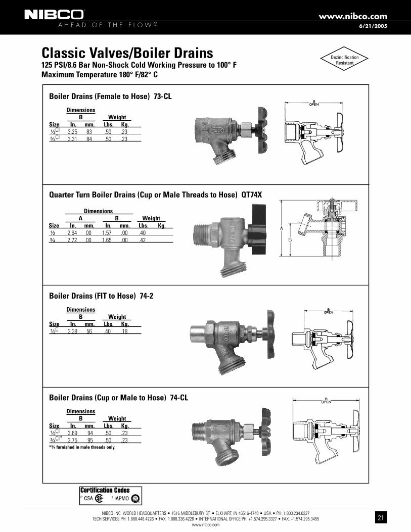
Classic Valves/Boiler Drains 125 PSI/8.6 Bar Non-Shock Cold Working Pressure to 100° f Maximum Temperature 180° f/82° C
Boiler Drains (female to Hose) 73-CL
Dimensions B Weight Size In. mm. Lbs. Kg. ¹⁄₂CI 3.25 83 .50 .23 ³⁄₄CI 3.31 84 .50 .23
Quarter Turn Boiler Drains (Cup or Male Threads to Hose) QT74X
Boiler Drains (fIT to Hose) 74-2
Dimensions B Weight Size In. mm. Lbs. Kg. ¹⁄₂C 3.38 56 .40 .18
Boiler Drains (Cup or Male to Hose) 74-CL
Dimensions B Weight Size In. mm. Lbs. Kg. ¹⁄₂CI 3.69 94 .50 .23 ³⁄₄CI* 3.75 95 .50 .23*³⁄₄ furnished in male threads only.
DezincificationResistant
Dimensions A B Weight Size In. mm. In. mm. Lbs. Kg. ¹⁄₂ 2.64 00 1.57 .00 .40 ³⁄₄ 2.72 00 1.65 .00 .42
6/21/2005

NIBCO INC. WORLD HEADQUARTERS • 1516 MIDDLEBURY ST. • ELKHART, IN 46516-4740 • USA • PH: 1.800.234.0227 TECH SERVICES PH: 1.888.446.4226 • FAX: 1.888.336.4226 • INTERNATIONAL OFFICE PH: +1.574.295.3327 • FAX: +1.574.295.3455
www.nibco.com
A H E A D O F T H E F L O W ®www.nibco.com
22
4660-S/4660-TOne-Piece Molded Body
150 PSI/10.3 Bar Non-Shock Cold Working Pressure to 73° f/23° C
4660-SSocket Weld
4660-SSocket x Socket
MATERIAL LIST PART SPECIfICATION 1. Handle Cap ABS 2. Screw Zinc-plated Steel 3. Handle ABS 4. O-Ring EPDM 5. Seat Seal PTFE, EPDM 6. Ball PVC 7. Body PVC
DIMENSIONS—WEIGHTS—QUANTITIES Dimensions Size C d3 H2 L L1 4660-S Master In. mm. In. mm. In. mm. In. mm. In. mm. In. mm. Lbs. Kg. Ctn. Qty. ¹⁄₂ 15 1.52 38 .55 14 1.69 43 3.27 83 2.76 69 .18 .08 100 ³⁄₄ 20 1.74 43 .79 20 2.13 54 3.74 93 3.47 87 .31 .14 100 1 25 1.92 48 .98 24 2.56 64 4.17 104 3.94 98 .49 .22 100 1 ¹⁄₄ 32 1.99 50 1.18 29 2.64 66 4.49 112 3.94 98 .57 .25 100 1 ¹⁄₂ 40 2.37 59 1.42 35 3.07 77 5.12 128 4.29 107 .88 .39 48 2 50 2.79 70 1.83 46 3.50 87 5.79 145 5.28 132 1.50 .67 48 2 ¹⁄₂ 65 4.53 113 2.36 59 4.13 103 8.03 201 7.01 175 2.73 1.23 12 3 80 5.27 132 3.03 76 4.88 122 9.02 225 8.82 220 4.01 1.80 12 4 100 7.31 183 3.98 99 5.83 146 11.81 295 10.87 272 8.29 3.73 6Socket ends per ASTM D 2466
Thread ends per ANSI B1.20.1
NSF STANDARD 14
4660-TThreaded x Threaded
4660-TThreaded
(not shown)
DezincificationResistant
6/21/2005

NIBCO INC. WORLD HEADQUARTERS • 1516 MIDDLEBURY ST. • ELKHART, IN 46516-4740 • USA • PH: 1.800.234.0227 TECH SERVICES PH: 1.888.446.4226 • FAX: 1.888.336.4226 • INTERNATIONAL OFFICE PH: +1.574.295.3327 • FAX: +1.574.295.3455
www.nibco.com
A H E A D O F T H E F L O W ®www.nibco.com
23
Bronze and Brass Ball ValvesIllustrated Index
Bronze Ball ValveConventional Port
150 lb. SWP600 lb. CWP
T-580-70Two-Piece Body • Blowout-Proof Stem
Sizes ¹⁄₄" thru 3"Threaded Ends
Page 25
Bronze Ball ValveStandard Port400 lb. CWP
T-580Two-Piece Body • Blowout-Proof Stem
Sizes ¹⁄₂" thru 2"Threaded Ends
Page 24
Brass Ball ValveFull Port
600 lb. CWP
T-fP-600Sizes ¹⁄₄" thru 4"Threaded Ends
Page 27
Bronze Ball ValveFull Port
150 lb. SWP600 lb. CWP
T-585-70Two-Piece Body • Blowout-Proof Stem
Sizes ¹⁄₄" thru 2"Threaded Ends
Page 26
DezincificationResistant
DezincificationResistant
WARNING: The body cavity around the ball of all ball valves should always be considered to contain media under pressure. The nature of the Quarter turn and floating ball allows media into the cavity, while in the closed position or anytime the valve is operated. The only means to assure
the cavity is drained and the pressure is relieved is to leave the ball in the half open/Half closed position when the line is drained.
DezincificationResistant
6/21/2005
NIBCO INC. WORLD HEADQUARTERS • 1516 MIDDLEBURY ST. • ELKHART, IN 46516-4740 • USA • PH: 1.800.234.0227 TECH SERVICES PH: 1.888.446.4226 • FAX: 1.888.336.4226 • INTERNATIONAL OFFICE PH: +1.574.295.3327 • FAX: +1.574.295.3455
www.nibco.com
A H E A D O F T H E F L O W ®www.nibco.com
24
for detailed Operating Pressure, refer to Pressure Temperature Chart on page 45.
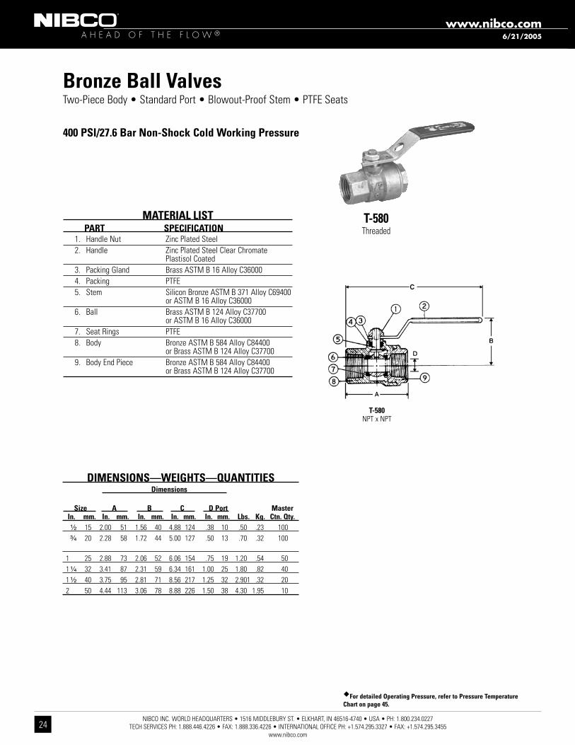
Two-Piece Body • Standard Port • Blowout-Proof Stem • PTFE Seats
400 PSI/27.6 Bar Non-Shock Cold Working Pressure
T-580Threaded
MATERIAL LIST PART SPECIfICATION 1. Handle Nut Zinc Plated Steel 2. Handle Zinc Plated Steel Clear Chromate Plastisol Coated 3. Packing Gland Brass ASTM B 16 Alloy C36000 4. Packing PTFE 5. Stem Silicon Bronze ASTM B 371 Alloy C69400 or ASTM B 16 Alloy C36000 6. Ball Brass ASTM B 124 Alloy C37700 or ASTM B 16 Alloy C36000 7. Seat Rings PTFE 8. Body Bronze ASTM B 584 Alloy C84400 or Brass ASTM B 124 Alloy C37700 9. Body End Piece Bronze ASTM B 584 Alloy C84400 or Brass ASTM B 124 Alloy C37700
DIMENSIONS—WEIGHTS—QUANTITIES Dimensions Size A B C D Port Master In. mm. In. mm. In. mm. In. mm. In. mm. Lbs. Kg. Ctn. Qty. ¹⁄₂ 15 2.00 51 1.56 40 4.88 124 .38 10 .50 .23 100 ³⁄₄ 20 2.28 58 1.72 44 5.00 127 .50 13 .70 .32 100
1 25 2.88 73 2.06 52 6.06 154 .75 19 1.20 .54 50 1 ¹⁄₄ 32 3.41 87 2.31 59 6.34 161 1.00 25 1.80 .82 40 1 ¹⁄₂ 40 3.75 95 2.81 71 8.56 217 1.25 32 2.901 .32 20 2 50 4.44 113 3.06 78 8.88 226 1.50 38 4.30 1.95 10
T-580NPT x NPT
Bronze Ball Valves
6/21/2005

NIBCO INC. WORLD HEADQUARTERS • 1516 MIDDLEBURY ST. • ELKHART, IN 46516-4740 • USA • PH: 1.800.234.0227 TECH SERVICES PH: 1.888.446.4226 • FAX: 1.888.336.4226 • INTERNATIONAL OFFICE PH: +1.574.295.3327 • FAX: +1.574.295.3455
www.nibco.com
A H E A D O F T H E F L O W ®www.nibco.com
25
DIMENSIONS—WEIGHTS—QUANTITIES Dimensions Size A B C D Port Master In. mm. In. mm. In. mm. In. mm. In. mm. Lbs. Kg. Ctn. Qty. ** ¹⁄₄ 8 2.00 51 1.75 44 5.00 127 .38 10 .45 .21 100 ** ³⁄₈ 10 2.00 51 1.75 44 5.00 127 .38 10 .45 .21 100 ** ¹⁄₂ 15 2.44 62 1.88 48 5.19 132 .50 13 .64 .29 100 ** ³⁄₄ 20 2.94 75 2.25 57 6.25 159 .75 19 1.33 .60 50 **1 25 3.34 94 2.38 60 6.44 164 1.00 25 1.79 .81 40 1 ¹⁄₄ 32 3.94 100 2.63 67 6.75 171 1.00 25 2.17 .98 20 1 ¹⁄₂ 40 4.31 110 3.00 76 8.88 226 1.25 32 3.27 1.48 20 2 50 4.63 117 3.25 83 9.06 230 1.50 38 5.09 2.31 10 2 ¹⁄₂ 65 5.84 148 3.53 90 9.66 245 2.00 51 8.25 3.74 6 3 80 7.09 180 4.41 112 11.53 293 2.50 64 15.65 7.10 4**NIBCO supplies full port T-585-70 on this size.
DezincificationResistant
Bronze Ball ValvesTwo-Piece Body • Full Port ¹⁄₄"-1" • Conventional Port 1¹⁄₄"-3" • Bronze Trim • Blowout-Proof Stem
600 PSI/41.4 Bar Non-Shock Cold Working Pressure150 PSI/10.3 Bar Saturated Steam
CONFORMS TO MSS SP-110MATERIAL LIST
PART SPECIfICATION 1. Handle Nut Zinc Plated Steel 2. Handle Zinc Plated Steel Clear Chromate Plastisol Coated 3. Threaded Pack Gland Brass ASTM B 16 Alloy C36000 4. Packing PTFE 5. Stem Silicon Bronze ASTM B 371 Alloy C69400 or ASTM B 99 Alloy C65100 6. Thrust Washer Reinforced PTFE 7. Ball Brass ASTM B 124 Alloy C37700 or ASTM B16 Alloy C36000 with Hard Chrome Plate 8. Seat Ring (2) Reinforced PTFE 9. Body Cast Red Bronze ASTM B 584 Alloy C84400 10. Body End Piece Cast Red Bronze ASTM B 584 Alloy C84400¹⁄₄" size only has a 304 stainless steel grounding washer.
T-580-70Threaded
T-580-70NPT x NPT
8/16/2005

NIBCO INC. WORLD HEADQUARTERS • 1516 MIDDLEBURY ST. • ELKHART, IN 46516-4740 • USA • PH: 1.800.234.0227 TECH SERVICES PH: 1.888.446.4226 • FAX: 1.888.336.4226 • INTERNATIONAL OFFICE PH: +1.574.295.3327 • FAX: +1.574.295.3455
www.nibco.com
A H E A D O F T H E F L O W ®www.nibco.com
26
DezincificationResistant
Bronze Ball ValvesTwo-Piece Body • Full Port • Bronze Trim • Blowout-Proof Stem
600 PSI/41.4 Bar Non-Shock Cold Working Pressure150 PSI/10.3 Bar Saturated Steam
CONFORMS TO MSS SP-110
T-585-70Threaded
MATERIAL LIST PART SPECIfICATION 1. Handle Nut Zinc Plated Steel 2. Handle Zinc Plated Steel Clear Chromate Plastisol Coated 3. Threaded Pack Gland Brass ASTM B 16 Alloy C36000 4. Packing PTFE 5. Stem Silicon Bronze ASTM B 371 Alloy C69430 or ASTM B 99 Alloy C65100 6. Thrust Washer Reinforced PTFE 7. Ball Brass ASTM B 124 Alloy C37700 or ASTM B16 Alloy C36000 with Hard Chrome Plate 8. Seat Ring (2) Reinforced PTFE 9. Body Cast Red Bronze ASTM B 584 Alloy C84400 10. Body End Piece Cast Red Bronze ASTM B 584 Alloy C84400¹⁄₄" size only has a 304 stainless steel grounding washer.
DIMENSIONS—WEIGHTS—QUANTITIES Dimensions Size A B C D Master In. mm. In. mm. In. mm. In. mm. In. mm. Lbs. Kg. Ctn. Qty. ¹⁄₄ 8 2.00 51 1.75 44 5.00 127 .38 10 .45 .21 100 ³⁄₈ 10 2.00 51 1.75 44 5.00 127 .38 10 .45 .21 100 ¹⁄₂ 15 2.44 62 1.88 48 5.19 132 .50 13 .64 .29 100 ³⁄₄ 20 2.94 75 2.25 57 6.25 159 .75 19 1.33 .60 50 1 25 3.34 85 2.38 60 6.44 164 1.00 25 1.79 .81 40 1 ¹⁄₄ 32 4.19 106 3.00 76 6.75 171 1.25 32 3.12 1.41 20 1 ¹⁄₂ 40 4.72 120 3.16 80 9.06 230 1.50 38 4.78 2.17 10 2 50 5.16 131 3.50 89 9.25 235 2.00 51 6.68 3.03 8
T-585-70NPT x NPT
8/16/2005

NIBCO INC. WORLD HEADQUARTERS • 1516 MIDDLEBURY ST. • ELKHART, IN 46516-4740 • USA • PH: 1.800.234.0227 TECH SERVICES PH: 1.888.446.4226 • FAX: 1.888.336.4226 • INTERNATIONAL OFFICE PH: +1.574.295.3327 • FAX: +1.574.295.3455
www.nibco.com
A H E A D O F T H E F L O W ®www.nibco.com
27
Brass Ball ValvesTwo-Piece Body • Full Port • Blowout-Proof Stem • PTFE Seats
¹⁄₄"-2" 600 PSI/41.4 Bar Non-Shock Cold Working Pressure2¹⁄₂"-4" 400 PSI/27.6 Bar Non-Shock Cold Working Pressure
UL SUBJECT 258 • FM1140 • ASME B16.44
T-fP-600Threaded
MATERIAL LIST PART SPECIfICATION 1. Handle Steel, Plated 2. Nut, Handle Steel, Plated 3. Pack Gland Brass ASTM B 16 Alloy C36000 4. Packing, Stem Virgin PTFE 5. Washer, Flat 430 Stainless 6. O-Ring (Stem Seal) Fluorocarbon (FKM) 7. Washer, Thrust Reinforced PTFE 8. Stem (3/8" - 3/4") Brass ASTM B 16 Alloy C36000 9. Body Forged Brass ASTM B 283 Alloy C37700 10. Seat Ring Virgin PTFE 11. Ball (3/8" - 3/4") Brass ASTM B 16 Alloy C36000 with Chrome Plate 12. End Piece Forged Brass ASTM B 283 Alloy C37700Note: AGA, CGA and UL approvals for T-fP-600 ¹⁄₂"-2" only.
CSA is now the approving agency for AGA and CGA standards. Meets Dimensional Requirements of MSS SP110
DIMENSIONS—WEIGHTS—QUANTITIES Dimensions Port Size A B C D Master In. mm. In. mm. In. mm. In. mm. In. mm. Lbs. Kg. Ctn. Qty.
¹⁄₄ 8 1.98 50 3.90 99 1.95 49 .31 8 .52 .24 24 ³⁄₈ 10 1.98 50 3.90 99 1.95 49 .38 10 .46 .21 24 ¹⁄₂ 15 2.22 56 3.34 85 1.95 49 .50 13 .48 .22 18 ³⁄₄ 20 2.66 67 3.34 85 2.30 58 .75 19 .90 .41 12 1 25 3.27 83 4.13 105 2.50 64 1.00 25 .60 1.25 6 1 ¹⁄₄ 32 3.66 93 4.13 105 3.07 78 1.25 32 2.14 .97 4 1 ¹⁄₂ 40 3.96 100 5.13 130 3.25 83 1.50 38 2.94 1.33 2 2 50 4.66 118 5.13 130 3.55 90 2.00 51 4.46 2.02 2 2 ¹⁄₂ 65 5.56 141 9.44 240 4.25 108 2.50 64 7.30 3.32 5 3 75 6.38 162 9.44 240 5.00 127 3.00 76 10.40 7.73 4 4 100 7.75 197 9.44 240 5.25 140 4.00 102 16.50 7.49 4
T-fP-600NPT x NPT
8/16/2005

NIBCO INC. WORLD HEADQUARTERS • 1516 MIDDLEBURY ST. • ELKHART, IN 46516-4740 • USA • PH: 1.800.234.0227 TECH SERVICES PH: 1.888.446.4226 • FAX: 1.888.336.4226 • INTERNATIONAL OFFICE PH: +1.574.295.3327 • FAX: +1.574.295.3455
www.nibco.com
A H E A D O F T H E F L O W ®www.nibco.com
28
Iron Body Gate ValvesIllustrated Index
Iron Body Gate ValveBolted Bonnet200 lb. CWP
f-619-RWNon-Rising Stem • Resilient Wedge
Sizes 2" thru 16"Flanged Ends
Page 30
Iron Body Gate ValveBolted Bonnet125 lb. SWP200 lb. CWP
f-619/T-619Non-Rising Stem • Solid Wedge
Sizes 2" thru 16"Flanged or Threaded Ends
Page 29
Iron Body Gate ValveBolted Bonnet200 lb. CWP
P-619-RWNon-Rising Stem • Resilient Wedge
Sizes 2" thru 12"IPS Push-On Ends
Page 33
Iron Body Gate ValveBolted Bonnet200 lb. CWP
Iron Body Gate ValveBolted Bonnet200 lb. CWP
MJ-619-RWNon-Rising Stem • Resilient Wedge
Sizes 3" thru 16"Mechanical Joint Ends
Page 32
fM-619-RW-SONNon-Rising Stem • Resilient Wedge
Sizes 3" thru 12"Flanged by MJ Ends
Page 31
8/16/2005

NIBCO INC. WORLD HEADQUARTERS • 1516 MIDDLEBURY ST. • ELKHART, IN 46516-4740 • USA • PH: 1.800.234.0227 TECH SERVICES PH: 1.888.446.4226 • FAX: 1.888.336.4226 • INTERNATIONAL OFFICE PH: +1.574.295.3327 • FAX: +1.574.295.3455
www.nibco.com
A H E A D O F T H E F L O W ®www.nibco.com
29
DIMENSIONS—WEIGHTS—QUANTITIES Dimensions f-619 T-619 Size A A B C D E f-619 T-619 In. mm. In. mm. In. mm. In. mm. In. mm. In. mm. In. mm. Lbs. Kg. Lbs. Kg. 2 50 7.00 178 5.63 143 11.00 279 7 178 6.00 152 .63 16 35 16 25 11 2¹⁄₂ 65 7.50 191 5.88 149 12.50 318 7 178 7.00 178 .69 17 49 22 33 15 3 80 8.00 203 6.13 156 13.50 343 8 203 7.50 191 .75 19 60 27 42 19 4 100 9.00 229 6.50 165 15.75 400 10 254 9.00 229 .94 24 90 41 61 28 5 125 10.00 254 x x 17.00 432 10 254 10.00 254 .94 24 129 59 x x 6 150 10.50 267 x x 21.00 533 12 305 11.00 279 1.00 25 161 73 x x 8 200 11.50 292 x x 25.00 635 14 356 13.50 343 1.13 29 277 126 x x10 250 13.00 330 x x 29.00 737 16 406 16.00 406 1.19 30 415 188 x x12 300 14.00 356 x x 34.50 876 18 457 19.00 483 1.25 32 631 287 x x 14 350 15.00 381 x x 40.38 1026 x x 21.00 533 1.38 35 869 394 x x 16 400 16.00 407 x x 45.75 1162 x x 23.50 597 1.44 37 1224 555 x xx Not available this size.
MATERIAL LIST PART SPECIfICATION 1. Handwheel Nut Steel ASTM A 307 2. Identification Plate Aluminum 3. Handwheel or Square Operating Nut Cast Iron ASTM A 126 Class B 4. Stem Brass ASTM B 16 Alloy C36000 5. Gland Follower Nut Bronze ASTM F 467 Alloy C27000 6. Gland Follower Cast Iron ASTM A 126 Class B or Ductile Iron ASTM A 536 7. Gland Follower Bolt Steel ASTM A 307 8. Packing Gland Zinc Plated Powdered Iron ASTM B 783 or Brass ASTM B 16 9. Stuffing Box Cast Iron ASTM A 126 Class B 10. Packing Synthetic Fibers with Graphite 11. Stuffing Box Gasket Synthetic Fibers 12. Bonnet Cast Iron ASTM A 126 Class B 13. Body Bolt ASTM A 307 14. Body Gasket Synthetic Fibers 15. Body Nut Steel ASTM A 307 16. 1 Wedge Bushing Cast Bronze ASTM B 584 Alloy C84400 17. Seat Ring Cast Bronze ASTM B 584 Alloy C84400 18. Wedge Face Ring Cast Bronze ASTM B 584 Alloy C84400 19. 1 Wedge Cast Iron ASTM A 126 Class B 20. Body Cast Iron ASTM A 126 Class B 21. Stuffing Box Nut Steel ASTM A 307 (not shown) 1 Sizes thru 6" have Bronze Wedges. Sizes 8" thru 12" made with Cast Iron Wedge
with Bronze Bushing and Wedge face Rings.
Class 125 Iron Body Gate ValvesBolted Bonnet • Non-Rising Stem • Solid Wedge • Bronze Mounted
125 PSI/8.6 Bar Saturated Steam to 353º f/178º C200 PSI/13.8 Bar Non-Shock Cold Working Pressureto -20º f to 150º f/-29º C to 66º C
CONFORMS TO MSS SP-70 f-619Flanged
f-619-SONFlanged
With Square Op. Nut
T-619Threaded
f-619Flg x Flg
T-619NPT x NPT
fREEzING WEATHER PRECAUTION: Subsequent to testing a piping system, valves should be left in an open position to allow complete drainage.
Position indicators available, see page 92.
for detailed Operating Pressure, refer to Pressure Temperature Chart on page 109.
6/22/2005
NIBCO INC. WORLD HEADQUARTERS • 1516 MIDDLEBURY ST. • ELKHART, IN 46516-4740 • USA • PH: 1.800.234.0227 TECH SERVICES PH: 1.888.446.4226 • FAX: 1.888.336.4226 • INTERNATIONAL OFFICE PH: +1.574.295.3327 • FAX: +1.574.295.3455
www.nibco.com
A H E A D O F T H E F L O W ®www.nibco.com
30
5/1/2012
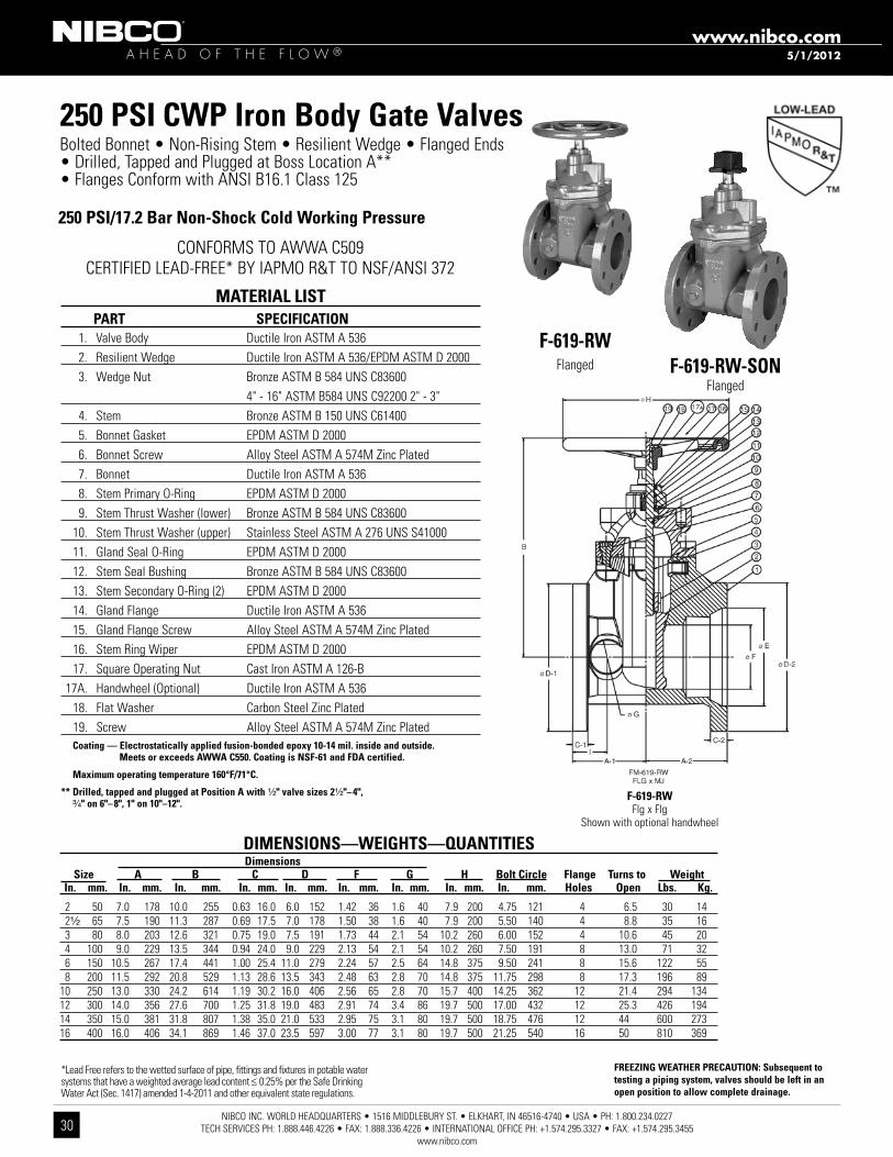
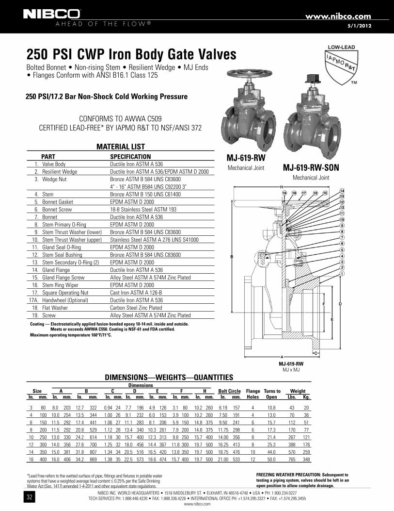
MATERIAL LIST PART SPECIfICATION 1. Valve Body Ductile Iron ASTM A 536 2. Resilient Wedge Ductile Iron ASTM A 536/EPDM ASTM D 2000 3. Wedge Nut Bronze ASTM B 584 UNS C83600 4" - 16" ASTM B584 UNS C92200 2" - 3" 4. Stem Bronze ASTM B 150 UNS C61400 5. Bonnet Gasket EPDM ASTM D 2000 6. Bonnet Screw Alloy Steel ASTM A 574M Zinc Plated 7. Bonnet Ductile Iron ASTM A 536 8. Stem Primary O-Ring EPDM ASTM D 2000 9. Stem Thrust Washer (lower) Bronze ASTM B 584 UNS C83600 10. Stem Thrust Washer (upper) Stainless Steel ASTM A 276 UNS S41000 11. Gland Seal O-Ring EPDM ASTM D 2000 12. Stem Seal Bushing Bronze ASTM B 584 UNS C83600 13. Stem Secondary O-Ring (2) EPDM ASTM D 2000 14. Gland Flange Ductile Iron ASTM A 536 15. Gland Flange Screw Alloy Steel ASTM A 574M Zinc Plated 16. Stem Ring Wiper EPDM ASTM D 2000 17. Square Operating Nut Cast Iron ASTM A 126-B 17A. Handwheel (Optional) Ductile Iron ASTM A 536 18. Flat Washer Carbon Steel Zinc Plated 19. Screw Alloy Steel ASTM A 574M Zinc Plated Coating — Electrostatically applied fusion-bonded epoxy 10-14 mil. inside and outside. Meets or exceeds AWWA C550. Coating is NSf-61 and fDA certified.
Maximum operating temperature 160°f/71°C.
** Drilled, tapped and plugged at Position A with ¹⁄₂" valve sizes 2¹⁄₂"–4", ³⁄₄" on 6"–8", 1" on 10"–12".
250 PSI CWP Iron Body Gate ValvesBolted Bonnet • Non-Rising Stem • Resilient Wedge • Flanged Ends • Drilled, Tapped and Plugged at Boss Location A** • Flanges Conform with ANSI B16.1 Class 125
250 PSI/17.2 Bar Non-Shock Cold Working Pressure
CONFORMS TO AWWA C509 CERTIFIED LEAD-FREE* BY IAPMO R&T TO NSF/ANSI 372
f-619-RW-SONFlanged
f-619-RWFlanged
f-619-RWFlg x Flg
Shown with optional handwheel
DIMENSIONS—WEIGHTS—QUANTITIES Dimensions Size A B C D f G H Bolt Circle flange Turns to Weight In. mm. In. mm. In. mm. In. mm. In. mm. In. mm. In. mm. In. mm. In. mm. Holes Open Lbs. Kg.
2 50 7.0 178 10.0 255 0.63 16.0 6.0 152 1.42 36 1.6 40 7.9 200 4.75 121 4 6.5 30 14 2¹⁄₂ 65 7.5 190 11.3 287 0.69 17.5 7.0 178 1.50 38 1.6 40 7.9 200 5.50 140 4 8.8 35 16 3 80 8.0 203 12.6 321 0.75 19.0 7.5 191 1.73 44 2.1 54 10.2 260 6.00 152 4 10.6 45 20 4 100 9.0 229 13.5 344 0.94 24.0 9.0 229 2.13 54 2.1 54 10.2 260 7.50 191 8 13.0 71 32 6 150 10.5 267 17.4 441 1.00 25.4 11.0 279 2.24 57 2.5 64 14.8 375 9.50 241 8 15.6 122 55 8 200 11.5 292 20.8 529 1.13 28.6 13.5 343 2.48 63 2.8 70 14.8 375 11.75 298 8 17.3 196 89 10 250 13.0 330 24.2 614 1.19 30.2 16.0 406 2.56 65 2.8 70 15.7 400 14.25 362 12 21.4 294 134 12 300 14.0 356 27.6 700 1.25 31.8 19.0 483 2.91 74 3.4 86 19.7 500 17.00 432 12 25.3 426 194 14 350 15.0 381 31.8 807 1.38 35.0 21.0 533 2.95 75 3.1 80 19.7 500 18.75 476 12 44 600 273 16 400 16.0 406 34.1 869 1.46 37.0 23.5 597 3.00 77 3.1 80 19.7 500 21.25 540 16 50 810 369
fREEzING WEATHER PRECAUTION: Subsequent to testing a piping system, valves should be left in an open position to allow complete drainage.
*Lead Free refers to the wetted surface of pipe, fittings and fixtures in potable water systems that have a weighted average lead content ≤ 0.25% per the Safe Drinking Water Act (Sec. 1417) amended 1-4-2011 and other equivalent state regulations.
NIBCO INC. WORLD HEADQUARTERS • 1516 MIDDLEBURY ST. • ELKHART, IN 46516-4740 • USA • PH: 1.800.234.0227 TECH SERVICES PH: 1.888.446.4226 • FAX: 1.888.336.4226 • INTERNATIONAL OFFICE PH: +1.574.295.3327 • FAX: +1.574.295.3455
www.nibco.com
A H E A D O F T H E F L O W ®www.nibco.com
31
DIMENSIONS—WEIGHTS—QUANTITIES Dimensions Size A-1 A-2 B C-1 C-2 D-1 D-2 E f In. mm. In. mm. In. mm. In. mm. In. mm. In. mm. In. mm. In. mm. In. mm. In. mm.
3 80 4.0 101.5 4.0 101.5 12.6 321 0.75 19.0 0.94 24 7.5 191 7.7 195.3 4.9 126 3.1 80 4 100 4.5 114.5 5.0 127.0 13.5 344 0.94 24.0 1.00 26 9.0 229 9.1 232.0 6.0 153 3.9 100 6 150 5.3 133.5 5.7 146.0 17.4 441 1.00 25.4 1.06 27 11.0 279 11.1 282.5 8.1 206 5.9 150 8 200 5.7 146.0 5.7 146.0 20.8 529 1.13 28.6 1.12 28 13.5 343 13.4 339.6 10.3 261 7.9 200 10 250 6.5 165.0 6.5 165.0 24.2 614 1.19 30.2 1.18 30 16.0 406 15.6 396.8 12.3 313 9.8 250 12 300 7.0 178.0 7.0 178.9 27.6 700 1.25 31.8 1.25 32 19.0 483 17.9 454.2 14.4 367 11.8 300
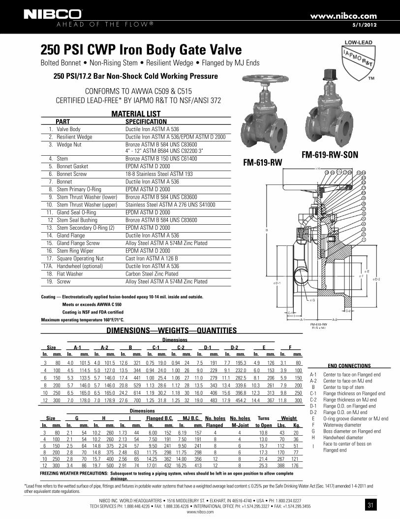
MATERIAL LIST PART SPECIfICATION 1. Valve Body Ductile Iron ASTM A 536 2. Resilient Wedge Ductile Iron ASTM A 536/EPDM ASTM D 2000 3. Wedge Nut Bronze ASTM B 584 UNS C83600 4" - 12" ASTM B584 UNS C92200 3" 4. Stem Bronze ASTM B 150 UNS C61400 5. Bonnet Gasket EPDM ASTM D 2000 6. Bonnet Screw 18-8 Stainless Steel ASTM 193 7. Bonnet Ductile Iron ASTM A 536 8. Stem Primary O-Ring EPDM ASTM D 2000 9. Stem Thrust Washer (lower) Bronze ASTM B 584 UNS C83600 10. Stem Thrust Washer (upper) Stainless Steel ASTM A 276 UNS S41000 11. Gland Seal O-Ring EPDM ASTM D 2000 12 Stem Seal Bushing Bronze ASTM B 584 UNS C83600 13. Stem Secondary O-Ring (2) EPDM ASTM D 2000 14. Gland Flange Ductile Iron ASTM A 536 15. Gland Flange Screw Alloy Steel ASTM A 574M Zinc Plated 16. Stem Ring Wiper EPDM ASTM D 2000 17. Square Operating Nut Cast Iron ASTM A 126 B 17A. Handwheel (optional) Ductile Iron ASTM A 536 18. Flat Washer Carbon Steel Zinc Plated 19. Screw Alloy Steel ASTM A 574M Zinc Plated Coating — Electrostatically applied fusion-bonded epoxy 10-14 mil. inside and outside.
Meets or exceeds AWWA C 550
Coating is NSf and fDA certified
Maximum operating temperature 160°f/71°C.
250 PSI CWP Iron Body Gate ValveBolted Bonnet • Non-Rising Stem • Resilient Wedge • Flanged by MJ Ends
250 PSI/17.2 Bar Non-Shock Cold Working Pressure
fM-619-RWfM-619-RW-SON
Dimensions Size G H I flanged B.C. MJ B.C. No. holes No. holes Turns Weight In. mm. In. mm. In. mm. In. mm. In. mm. In. mm. flanged M-Joint to Open Lbs. Kg. 3 80 2.1 54 10.2 260 1.73 44 6.00 152 6.19 157 4 4 10.8 43 20 4 100 2.1 54 10.2 260 2.13 54 7.50 191 7.50 191 8 4 13.0 70 36 6 150 2.5 64 14.8 375 2.24 57 9.50 241 9.50 241 8 6 15.7 112 51 8 200 2.8 70 14.8 375 2.48 63 11.75 298 11.75 298 8 6 17.3 170 77 10 250 2.8 70 15.7 400 2.56 65 14.25 362 14.00 356 12 8 21.4 267 121 12 300 3.4 86 19.7 500 2.91 74 17.01 432 16.25 413 12 8 25.3 388 176fREEzING WEATHER PRECAUTIONS: Subsequent to testing a piping system, valves should be left in an open position to allow complete drainage.
END CONNECTIONS
A-1 Center to face on Flanged end A-2 Center to face on MJ end B Center to top of stem C-1 Flange thickness on Flanged end C-2 Flange thickness on MJ end D-1 Flange O.D. on Flanged end D-2 Flange O.D. on MJ end E O-ring groove diameter or MJ end F Waterway diameter G Boss diameter on Flanged end H Handwheel diameter I Face to center of boss on Flanged end
5/1/2012
*Lead Free refers to the wetted surface of pipe, fittings and fixtures in potable water systems that have a weighted average lead content ≤ 0.25% per the Safe Drinking Water Act (Sec. 1417) amended 1-4-2011 and other equivalent state regulations.
CONFORMS TO AWWA C509 & C515 CERTIFIED LEAD-FREE* BY IAPMO R&T TO NSF/ANSI 372
NIBCO INC. WORLD HEADQUARTERS • 1516 MIDDLEBURY ST. • ELKHART, IN 46516-4740 • USA • PH: 1.800.234.0227 TECH SERVICES PH: 1.888.446.4226 • FAX: 1.888.336.4226 • INTERNATIONAL OFFICE PH: +1.574.295.3327 • FAX: +1.574.295.3455
www.nibco.com
A H E A D O F T H E F L O W ®www.nibco.com
32
5/1/2012
MATERIAL LIST PART SPECIfICATION 1. Valve Body Ductile Iron ASTM A 536 2. Resilient Wedge Ductile Iron ASTM A 536/EPDM ASTM D 2000 3. Wedge Nut Bronze ASTM B 584 UNS C83600 4" - 16" ASTM B584 UNS C92200 3" 4. Stem Bronze ASTM B 150 UNS C61400 5. Bonnet Gasket EPDM ASTM D 2000 6. Bonnet Screw 18-8 Stainless Steel ASTM 193 7. Bonnet Ductile Iron ASTM A 536 8. Stem Primary O-Ring EPDM ASTM D 2000 9. Stem Thrust Washer (lower) Bronze ASTM B 584 UNS C83600 10. Stem Thrust Washer (upper) Stainless Steel ASTM A 276 UNS S41000 11. Gland Seal O-Ring EPDM ASTM D 2000 12. Stem Seal Bushing Bronze ASTM B 584 UNS C83600 13. Stem Secondary O-Ring (2) EPDM ASTM D 2000 14. Gland Flange Ductile Iron ASTM A 536 15. Gland Flange Screw Alloy Steel ASTM A 574M Zinc Plated 16. Stem Ring Wiper EPDM ASTM D 2000 17. Square Operating Nut Cast Iron ASTM A 126-B 17A. Handwheel (Optional) Ductile Iron ASTM A 536 18. Flat Washer Carbon Steel Zinc Plated 19. Screw Alloy Steel ASTM A 574M Zinc Plated
Coating — Electrostatically applied fusion-bonded epoxy 10-14 mil. inside and outside. Meets or exceeds AWWA C550. Coating is NSf-61 and fDA certified.
Maximum operating temperature 160°f/71°C.
250 PSI CWP Iron Body Gate ValvesBolted Bonnet • Non-rising Stem • Resilient Wedge • MJ Ends • Flanges Conform with ANSI B16.1 Class 125
250 PSI/17.2 Bar Non-Shock Cold Working Pressure
CONFORMS TO AWWA C509 CERTIFIED LEAD-FREE* BY IAPMO R&T TO NSF/ANSI 372
MJ-619-RW-SONMechanical Joint
MJ-619-RWMechanical Joint
MJ-619-RW MJ x MJ
DIMENSIONS—WEIGHTS—QUANTITIES Dimensions Size A B C D E f H Bolt Circle flange Turns to Weight In. mm. In. mm. In. mm. In. mm. In. mm. In. mm. In. mm. In. mm. In. mm. Holes Open Lbs. Kg.
3 80 8.0 203 12.7 322 0.94 24 7.7 196 4.9 126 3.1 80 10.2 260 6.19 157 4 10.8 43 20 4 100 10.0 254 13.5 344 1.00 26 9.1 232 6.0 153 3.9 100 10.2 260 7.50 191 4 13.0 70 36 6 150 11.5 292 17.4 441 1.06 27 11.1 283 8.1 206 5.9 150 14.8 375 9.50 241 6 15.7 112 51 8 200 11.5 292 20.8 529 1.12 28 13.4 340 10.3 261 7.9 200 14.8 375 11.75 298 6 17.3 170 77 10 250 13.0 330 24.2 614 1.18 30 15.7 400 12.3 313 9.8 250 15.7 400 14.00 356 8 21.4 267 121 12 300 14.0 356 27.6 700 1.25 32 18.0 456 14.4 367 11.8 300 19.7 500 16.25 413 8 25.3 388 176 14 350 15.0 381 31.8 807 1.34 34 20.5 516 16.5 420 13.8 350 19.7 500 18.75 476 10 44.0 570 259 16 400 16.0 406 34.2 869 1.38 35 22.5 573 18.6 474 15.7 400 19.7 500 21.00 533 12 50.0 765 348
fREEzING WEATHER PRECAUTION: Subsequent to testing a piping system, valves should be left in an open position to allow complete drainage.
*Lead Free refers to the wetted surface of pipe, fittings and fixtures in potable water systems that have a weighted average lead content ≤ 0.25% per the Safe Drinking Water Act (Sec. 1417) amended 1-4-2011 and other equivalent state regulations.

NIBCO INC. WORLD HEADQUARTERS • 1516 MIDDLEBURY ST. • ELKHART, IN 46516-4740 • USA • PH: 1.800.234.0227 TECH SERVICES PH: 1.888.446.4226 • FAX: 1.888.336.4226 • INTERNATIONAL OFFICE PH: +1.574.295.3327 • FAX: +1.574.295.3455
www.nibco.com
A H E A D O F T H E F L O W ®www.nibco.com
33
5/1/2012
MATERIAL LIST PART SPECIfICATION 1. Valve Body Cast Iron ASTM A 126-B 2. Resilient Wedge Ductile Iron ASTM A 536/EPDM ASTM D 2000 3. Wedge Nut Bronze ASTM B 584 UNS C83600 4" - 12" ASTM B584 UNS C92200 2" - 3" 4. Stem Stainless Steel ASTM A 276 UNS S41000 5. Bonnet Gasket EPDM ASTM D 2000 6. Bonnet Screw 18-8 Stainless Steel ASTM A193 7. Bonnet Cast Iron ASTM A 126-B 8. Stem Primary O-Ring EPDM ASTM D 2000 9. Stem Thrust Washer (lower) Nylon 1010 10. Stem Collar Brass ASTM B 16 UNS C36000 11. Stem Thrust Washer (upper) Stainless Steel ASTM A 276 UNS S41000 12, Gland Seal O-Ring EPDM ASTM D 2000 13. Stem Seal Bushing Nylon 1010 14. Stem Secondary O-Ring (2) EPDM ASTM D 2000 15. Gland Flange Ductile Iron ASTM A 536 16. Stem Ring Wiper EPDM ASTM D 2000 17. Square Operating Nut Cast Iron ASTM A 126-B 17A. Handwheel (Optional) Ductile Iron ASTM A 536 18. Operating Nut Washer Carbon Steel Zinc Plated 19. Operating Nut Screw Alloy Steel ASTM A 574M Zinc Plated 20. Gland Flange Screw Alloy Steel ASTM A 574M Zinc Plated
Coating — Electrostatically applied fusion-bonded epoxy 10-14 mil. inside and outside. Meets or exceeds AWWA C550. Coating is NSf-61 and fDA certified.
Maximum operating temperature 160°f/71°C.
250 PSI CWP Iron Body Gate ValvesBolted Bonnet • Non-Rising Stem • Resilient Wedge • IPS PVC Push-on
250 PSI/17.2 Bar Non-Shock Cold Working Pressure
P-619-RWIPS Push-On
P-619-RWIPS Push-On
DIMENSIONS—WEIGHTS—QUANTITIES Dimensions
Size A B C D E f Handwheel (Opt.) Turns to Weight
In. mm. In. mm. In. mm. In. mm. In. mm. In. mm. In. mm. In. mm. Open Lbs. Kg. 2 50 11.4 289 10.2 259 2.4 60 2.48 63 2.3 58 2.7 69 7.9 200 6.5 24 11 2¹⁄₂ 65 11.4 289 11.3 288 2.6 67 2.99 76 2.3 58 2.7 69 7.9 200 8.8 32 15 3 80 11.3 287 12.7 322 3.1 80 3.62 92 2.2 56 3.0 75 10.2 250 10.6 40 18 4 100 11.7 298 13.4 341 3.5 90 4.65 118 2.5 63 3.5 89 10.2 260 12.8 56 25 6 150 15.3 388 17.0 431 4.7 120 6.77 172 4.0 101 4.1 103 14.8 375 15.6 106 48 8 200 16.5 418 20.4 518 5.9 150 8.74 222 3.0 77 4.5 115 14.8 375 17.3 172 78 10 250 21.2 539 23.8 604 7.1 180 10.94 278 3.7 93 5.2 132 15.7 400 21.3 307 140 12 300 26.5 672 27.0 685 8.1 206 12.89 327.5 4.1 103 5.5 139 19.7 500 25.3 447 203
fREEzING WEATHER PRECAUTION: Subsequent to testing a piping system, valves should be left in an open position to allow complete drainage.
*Lead Free refers to the wetted surface of pipe, fittings and fixtures in potable water systems that have a weighted average lead content ≤ 0.25% per the Safe Drinking Water Act (Sec. 1417) amended 1-4-2011 and other equivalent state regulations.
CERTIFIED LEAD-FREE* BY IAPMO R&T TO NSF/ANSI 372

NIBCO INC. WORLD HEADQUARTERS • 1516 MIDDLEBURY ST. • ELKHART, IN 46516-4740 • USA • PH: 1.800.234.0227 TECH SERVICES PH: 1.888.446.4226 • FAX: 1.888.336.4226 • INTERNATIONAL OFFICE PH: +1.574.295.3327 • FAX: +1.574.295.3455
www.nibco.com
A H E A D O F T H E F L O W ®www.nibco.com
34
Iron Body Check ValvesIllustrated Index
Iron Body Silent Check ValveSpring Actuated TypeClass 125/200 CWPClass 250/400 CWP
W-910/W-960Renewable Seat and Disc • Wafer Style
Sizes 2" thru 12"Page 36
Iron Body Check ValveHorizontal Swing Type
125 lb. SWP200 lb. CWP
f-918/T-918Bolted Bonnet • Renewable Seat and Disc
Sizes 2" thru 12"Flanged or Threaded Ends
Page 35
6/22/2005

NIBCO INC. WORLD HEADQUARTERS • 1516 MIDDLEBURY ST. • ELKHART, IN 46516-4740 • USA • PH: 1.800.234.0227 TECH SERVICES PH: 1.888.446.4226 • FAX: 1.888.336.4226 • INTERNATIONAL OFFICE PH: +1.574.295.3327 • FAX: +1.574.295.3455
www.nibco.com
A H E A D O F T H E F L O W ®www.nibco.com
35
DIMENSIONS—WEIGHTS—QUANTITIES Dimensions f-918-B T-918-B Size A A B D E f-918-B T-918-B In. mm. In. mm. In. mm. In. mm. In. mm. In. mm. Lbs. Kg. Lbs. Kg. 2 50 8.00 203 6.50 165 3.94 100 6.00 152 .63 16 24 11 15 7 2¹⁄₂ 65 8.50 216 7.50 191 4.50 114 7.00 178 .69 17 35 16 26 12 3 80 9.50 241 8.00 203 5.13 130 7.50 191 .75 19 47 21 31 14 4 100 11.50 292 9.38 238 6.13 156 9.00 229 .94 24 80 36 54 24 5 125 13.00 330 10.63 270 6.81 173 10.00 254 .94 24 100 45 80 36 6 150 14.00 356 12.25 311 8.00 203 11.00 279 1.00 25 146 66 121 54 8 200 19.50 495 x x 9.44 240 13.50 343 1.13 29 274 124 x x 10 250 24.50 622 x x 12.06 306 16.00 406 1.19 30 426 193 x x 12 300 27.50 699 x x 16.13 410 19.00 483 1.25 32 675 306 x xNote: On pump discharge, the preferred check valves are one of the following types: “in-line spring loaded or swing
design with lever and weight or with lever and spring.” You should also install the check valve as far from the pump as possible and at a minimum length of 5 times the pipe diameter. flow staighteners may be required.
* Proper machining facilities required.
x Not available this size.
2¹⁄₂" thru 12" are available with lever and weight or lever and spring.
Swing Check valves should be sized for a 0.50 PSI pressure drop.
MATERIAL LIST PART SPECIfICATION 1. Body Bolt Steel ASTM A 307 2. Identification Plate Aluminum 3. Bonnet Cast Iron ASTM A 126 Class B 4. Body Gasket Synthetic Fibres 5. Body Nut Steel ASTM A 307 6. Side Plug Brass ASTM B 16 Alloy C36000 7. Hanger Pin Brass ASTM B 16 Alloy C36000 8. 2 Hanger Cast Bronze ASTM B 584 Alloy C84400 9. 1 Disc Cast Bronze ASTM B 584 Alloy C84400 or ASTM A 536 Ductile Iron with Bronze Face Ring 10. Seat Ring Cast Bronze ASTM B 584 Alloy C84400 11. Disc Nut Brass ASTM B 16 Alloy C36000 12. Body Cast Iron ASTM A 126 Class B 13. 1 Disc Bolt Brass ASTM B 16 Alloy C36000 14. Disc Plate Cast Iron ASTM A 126 Class B 15. Disc Cage Cast Iron ASTM A 126 Class B1 2" thru 4" have Bronze ASTM B 62 Disc.
5" thru 12" have Iron Disc with Bronze Disc face Rings and Disc Bolt.2 10" is Ductile Iron ASTM A 536.
Class 125 Iron Body Check ValvesBolted Bonnet • Horizontal Swing • *Renewable Seat and Disc
125 PSI/8.6 Bar Saturated Steam to 353º f/178º C200 PSI/13.8 Bar Non-Shock Cold Working Pressureto -20º f to 150º f/-29º C to 66º C
CONFORMS TO MSS SP-71 TYPE 1f-918-B
Flanged
T-918-BThreaded
f-918-BFlg x Flg
T-918NPT x NPT
WARNING: Do not use for Reciprocating Air Compressor Service.
NIBCO Iron Body Check Valves may be installed in both horizontal and vertical lines with upward flow or in any intermediate position.
6/22/2005

NIBCO INC. WORLD HEADQUARTERS • 1516 MIDDLEBURY ST. • ELKHART, IN 46516-4740 • USA • PH: 1.800.234.0227 TECH SERVICES PH: 1.888.446.4226 • FAX: 1.888.336.4226 • INTERNATIONAL OFFICE PH: +1.574.295.3327 • FAX: +1.574.295.3455
www.nibco.com
A H E A D O F T H E F L O W ®www.nibco.com
36
DIMENSIONS—WEIGHTS—QUANTITIES Dimensions Size A B W-910 W-960 In. mm. In. mm. In. mm. Lbs. Kg. Lbs. Kg. *2 50 4.25 108 2.63 67 6 3 6 3 *2¹⁄₂ 65 5.00 127 2.88 73 7 3 7 3 *3 80 5.75 146 3.13 79 12 5 12 5 *4 100 7.00 178 4.00 102 18 8 18 8 *5 125 8.75 222 4.75 121 27 12 27 12 *6 150 9.75 248 5.50 140 42 19 42 19 8 200 13.38 340 6.50 165 †85 39 ‡86 39 10 250 16.00 406 8.25 210 †146 66 ‡137 62
*NOTE: Sizes 2" thru 6" have dual class ratings (125 lb. and 250 lb.) resulting in W-910 and W-960 being identical. 8" and 12" have special machining in accordance with flange Class.
316 Stainless Steel Trim available – Consult factory.
† Class 125 only.‡ Class 250 only.
USE THIS VALVE ONLY WITH fLAT fACE fLANGE AND fULL fACE GASKET
WARNING: 1. Seat end of valve must be mated to a standard flat faced metal flange. Rubber flanges not acceptable.
2. These are not to be used as steam valves. 3. Valves are not to be used near a reciprocating air
compressor. 4. Install 5 pipe diameters minimum downstream from
pump discharge or elbows to avoid flow turbulence. flow straighteners may be required in extreme cases.
NOTE: On pump discharge, the preferred check valves are an in-line spring loaded, swing design with lever and weight or lever and spring.
Wafer Check valves should be sized for a 3.0 PSI pressure drop.
MATERIAL LIST PART SPECIfICATION 1. Body Cast Iron ASTM A 126 Class B 2. Seat Bronze ASTM B 584 Alloy C83600 (B) 2a. Seat Buna-N Bonded to Bronze (W) 3. Disc Bronze ASTM B 584 Alloy C83600 4. Spring Stainless Steel Type 316 ASTM A 313 5. Bushing 6" and smaller ASTM B 16 Alloy C36000 6. Set Screws Stainless Steel Type 304 ASTM F 879
Class 125/250 Iron Body Silent Check ValvesWafer Style • Renewable Seat and Disc • Spring Actuated
Class 125, 200 PSI/13.8 Bar Non-Shock Cold Working PressureClass 250, 400 PSI/27.6 Bar Non-Shock Cold Working PressureMaximum Temperature to 200º f/93º C
CONFORMS TO MSS SP-71 TYPE 1 • FM APPROVED (CLASS 125)
W-910 125 lb. ClassW-960 250 lb. Class
W-910-W/W-960-WWafer
W-910-B/W-960-BWafer
W-910-B/W-960-BWafer
8/16/2005

NIBCO INC. WORLD HEADQUARTERS • 1516 MIDDLEBURY ST. • ELKHART, IN 46516-4740 • USA • PH: 1.800.234.0227 TECH SERVICES PH: 1.888.446.4226 • FAX: 1.888.336.4226 • INTERNATIONAL OFFICE PH: +1.574.295.3327 • FAX: +1.574.295.3455
www.nibco.com
A H E A D O F T H E F L O W ®www.nibco.com
37
Iron Body Butterfly ValvesIllustrated Index
Iron Body Butterfly ValveDuctile Iron Body
200 lb. CWP
LD-2000/WD-2000Extended Neck • Molded Insert Liner
Lug or Wafer StyleSizes 2" thru 12"
Page 38
Iron Body Butterfly ValveDuctile Iron body
150 lb. CWP
LD-1000Extended Neck • Cartridge Seat Liner
Lug StyleSizes 14" thru 24"
Page 39
Iron Body Butterfly ValveCast Iron Body200 lb. CWP
N-200Extended Neck • Cartridge Seat Liner
Lug StyleSizes 2" thru 12"
Page 40
Iron Body Butterfly ValveCast Iron Body200 lb. CWP
N-200Extended Neck • Cartridge Seat Liner
Wafer StyleSizes 2" thru 12"
Page 41
6/22/2005
NIBCO INC. WORLD HEADQUARTERS • 1516 MIDDLEBURY ST. • ELKHART, IN 46516-4740 • USA • PH: 1.800.234.0227 TECH SERVICES PH: 1.888.446.4226 • FAX: 1.888.336.4226 • INTERNATIONAL OFFICE PH: +1.574.295.3327 • FAX: +1.574.295.3455
www.nibco.com
A H E A D O F T H E F L O W ®www.nibco.com
38
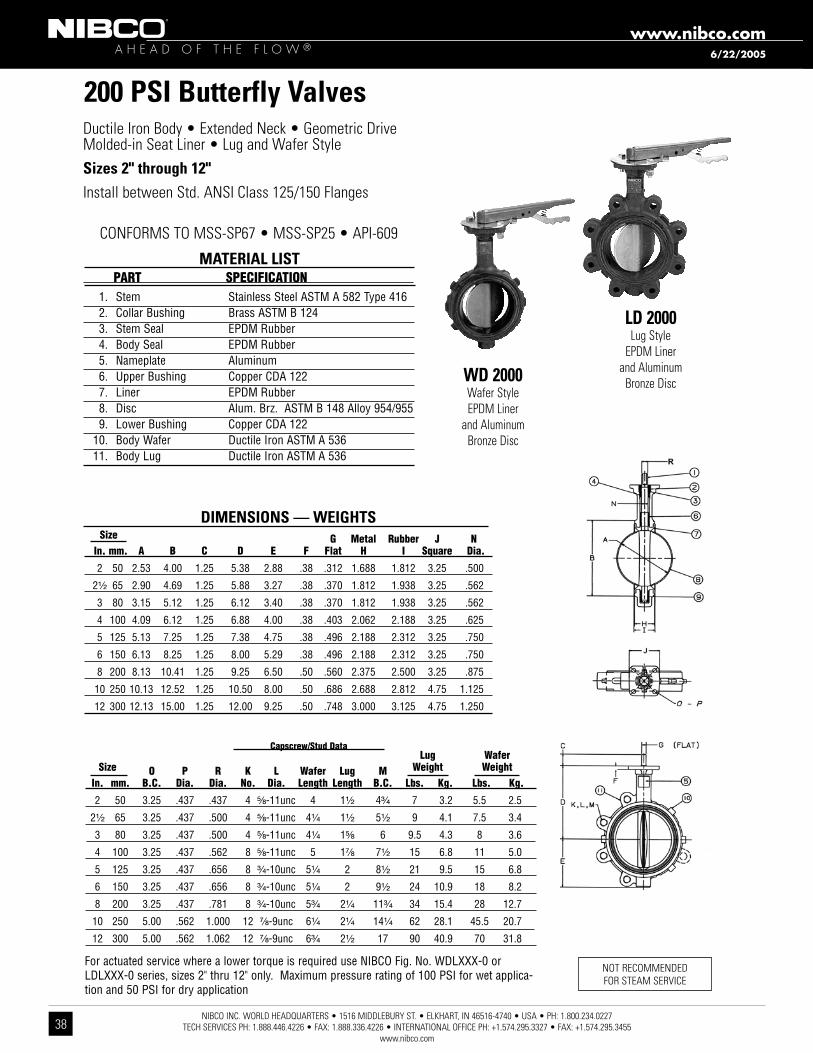
200 PSI Butterfly ValvesDuctile Iron Body • Extended Neck • Geometric DriveMolded-in Seat Liner • Lug and Wafer Style Sizes 2" through 12"Install between Std. ANSI Class 125/150 Flanges
1. Stem Stainless Steel ASTM A 582 Type 416 2. Collar Bushing Brass ASTM B 124 3. Stem Seal EPDM Rubber 4. Body Seal EPDM Rubber 5. Nameplate Aluminum 6. Upper Bushing Copper CDA 122 7. Liner EPDM Rubber 8. Disc Alum. Brz. ASTM B 148 Alloy 954/955 9. Lower Bushing Copper CDA 122 10. Body Wafer Ductile Iron ASTM A 536 11. Body Lug Ductile Iron ASTM A 536
MATERIAL LIST Part SPecification
DIMENSIONS — WEIGHTS Size G Metal rubber J n in. mm. a B c D e f flat H i Square Dia.
2 50 2.53 4.00 1.25 5.38 2.88 .38 .312 1.688 1.812 3.25 .500
2¹⁄₂ 65 2.90 4.69 1.25 5.88 3.27 .38 .370 1.812 1.938 3.25 .562
3 80 3.15 5.12 1.25 6.12 3.40 .38 .370 1.812 1.938 3.25 .562
4 100 4.09 6.12 1.25 6.88 4.00 .38 .403 2.062 2.188 3.25 .625
5 125 5.13 7.25 1.25 7.38 4.75 .38 .496 2.188 2.312 3.25 .750
6 150 6.13 8.25 1.25 8.00 5.29 .38 .496 2.188 2.312 3.25 .750
8 200 8.13 10.41 1.25 9.25 6.50 .50 .560 2.375 2.500 3.25 .875
10 250 10.13 12.52 1.25 10.50 8.00 .50 .686 2.688 2.812 4.75 1.125
12 300 12.13 15.00 1.25 12.00 9.25 .50 .748 3.000 3.125 4.75 1.250
LD 2000Lug Style
EPDM Liner and Aluminum
Bronze DiscWD 2000Wafer StyleEPDM Liner
and Aluminum Bronze Disc
NOT RECOMMENDED FOR STEAM SERVICE
capscrew/Stud Data
CONFORMS TO MSS-SP67 • MSS-SP25 • API-609
For actuated service where a lower torque is required use NIBCO Fig. No. WDLXXX-0 or LDLXXX-0 series, sizes 2" thru 12" only. Maximum pressure rating of 100 PSI for wet applica-tion and 50 PSI for dry application
6/22/2005
Lug Wafer Size o P r K L Wafer Lug M Weight Weight in. mm. B.c. Dia. Dia. no. Dia. Length Length B.c. Lbs. Kg. Lbs. Kg.
2 50 3.25 .437 .437 4 ⁵⁄₈-11unc 4 1¹⁄₂ 4³⁄₄ 7 3.2 5.5 2.5
2¹⁄₂ 65 3.25 .437 .500 4 ⁵⁄₈-11unc 4¹⁄₄ 1¹⁄₂ 5¹⁄₂ 9 4.1 7.5 3.4
3 80 3.25 .437 .500 4 ⁵⁄₈-11unc 4¹⁄₄ 1⁵⁄₈ 6 9.5 4.3 8 3.6
4 100 3.25 .437 .562 8 ⁵⁄₈-11unc 5 1⁷⁄₈ 7¹⁄₂ 15 6.8 11 5.0
5 125 3.25 .437 .656 8 ³⁄₄-10unc 5¹⁄₄ 2 8¹⁄₂ 21 9.5 15 6.8
6 150 3.25 .437 .656 8 ³⁄₄-10unc 5¹⁄₄ 2 9¹⁄₂ 24 10.9 18 8.2
8 200 3.25 .437 .781 8 ³⁄₄-10unc 5³⁄₄ 2¹⁄₄ 11³⁄₄ 34 15.4 28 12.7
10 250 5.00 .562 1.000 12 ⁷⁄₈-9unc 6¹⁄₄ 2¹⁄₄ 14¹⁄₄ 62 28.1 45.5 20.7
12 300 5.00 .562 1.062 12 ⁷⁄₈-9unc 6³⁄₄ 2¹⁄₂ 17 90 40.9 70 31.8
NIBCO INC. WORLD HEADQUARTERS • 1516 MIDDLEBURY ST. • ELKHART, IN 46516-4740 • USA • PH: 1.800.234.0227 TECH SERVICES PH: 1.888.446.4226 • FAX: 1.888.336.4226 • INTERNATIONAL OFFICE PH: +1.574.295.3327 • FAX: +1.574.295.3455
www.nibco.com
A H E A D O F T H E F L O W ®www.nibco.com
39
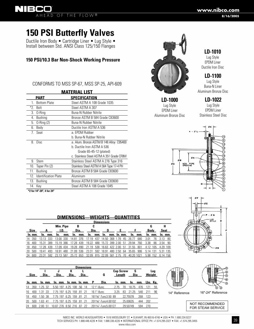
150 PSI Butterfly ValvesDuctile Iron Body • Cartridge Liner • Lug Style • Install between Std. ANSI Class 125/150 Flanges
LD-1000Lug Style
EPDM Liner Aluminum Bronze Disc
LD-1010Lug Style
EPDM LinerDuctile Iron Disc
LD-1100Lug Style
Buna-N LinerAluminum Bronze Disc
LD-1022Lug Style
EPDM LinerStainless Steel Disc
MATERIAL LIST PART SPECIfICATION 1. Bottom Plate Steel ASTM A 108 Grade 1035 *2. Bolt Steel ASTM A 307 3. O-Ring Buna-N Rubber Nitrile 4. Bushing Bronze ASTM B 584 Grade C83600 5. O-Ring (2) Buna-N Rubber Nitrile 6. Body Ductile Iron ASTM A 536 7. Seat a. EPDM Rubber b. Buna-N Rubber Nitrile 8. Disc a. Alum. Bronze ASTM B 148 Alloy C95400 b. Ductile Iron ASTM A 536 Grade 65-45-12 (plated) c. Stainless Steel ASTM A 351 Grade CF8M 9. Stem Stainless Steel ASTM A 276 Type 316 10. Taper Pin (2) Stainless Steel ASTM A 564 Type 17-4 PH 11. Bushing Bronze ASTM B 584 Grade C83600 12. Identification Plate Aluminum 13. Bushing Bronze ASTM B 584 Grade C83600 14. Key Steel ASTM A 108 Grade 1045 *2 for 14"-20", 4 for 24"
DIMENSIONS—WEIGHTS—QUANTITIES Dimensions Min. Pipe B C G H Size A I.D. Dia. Dia. D E f Body Seat In. mm. In. mm. In. mm. In. mm. In. mm. In. mm. In. mm. In. mm. In. mm. In. mm. 14 350 13.13 333 13.00 330 14.81 376 17.19 437 14.50 368 1.78 45 26.77 680 3.01 76 3.13 80 16 400 15.31 389 15.19 386 17.28 439 19.22 488 15.72 399 2.00 51 29.94 760 3.38 86 3.54 90 18 450 17.28 439 17.09 434 19.28 490 21.19 538 16.63 422 2.00 51 31.55 801 4.12 105 4.29 109 20 500 19.41 493 18.91 480 21.09 536 23.31 592 18.91 480 2.50 64 35.65 906 5.14 131 5.31 135 24 600 23.31 592 23.13 587 25.72 653 32.09 815 22.09 561 2.75 70 40.20 1021 5.98 152 6.14 156
Not RecommeNded foR Steam SeRvice
Dimensions I J K L Cap Screw S Lug Size Dia. Dia. Dia. Dia. Q Length Dia Weight
In. mm. In. mm. In. mm. In. mm. In. mm. P Dia. In. mm. In. mm. Lbs. Kg. 14 350 1.25 32 5.50 197 4.25 108 .56 14 12 1"-8unc 2.75 70 18.75 476 121 5516 400 1.31 33 7.75 197 6.25 159 .81 21 16 1"-8unc 3.25 83 21.25 540 211 96 18 450 1.50 38 7.75 197 6.25 159 .81 21 16 1¹⁄₈"-7unc 3.50 89 22.75 578 268 123 20 500 1.63 41 7.75 197 6.25 159 .81 21 20 1¹⁄₈"-7unc 4.00 102 25.00 635 444 202 24 600 2.00 51 10.87 276 8.50 216 .87 22 20 1¹⁄₄"-7unc 5.00 127 29.50 749 594 270
14" Reference 16"-24" Reference
CONFORMS TO MSS SP-67, MSS SP-25, API-609
150 PSI/10.3 Bar Non-Shock Working Pressure
8/16/2005
NIBCO INC. WORLD HEADQUARTERS • 1516 MIDDLEBURY ST. • ELKHART, IN 46516-4740 • USA • PH: 1.800.234.0227 TECH SERVICES PH: 1.888.446.4226 • FAX: 1.888.336.4226 • INTERNATIONAL OFFICE PH: +1.574.295.3327 • FAX: +1.574.295.3455
www.nibco.com
A H E A D O F T H E F L O W ®www.nibco.com
40
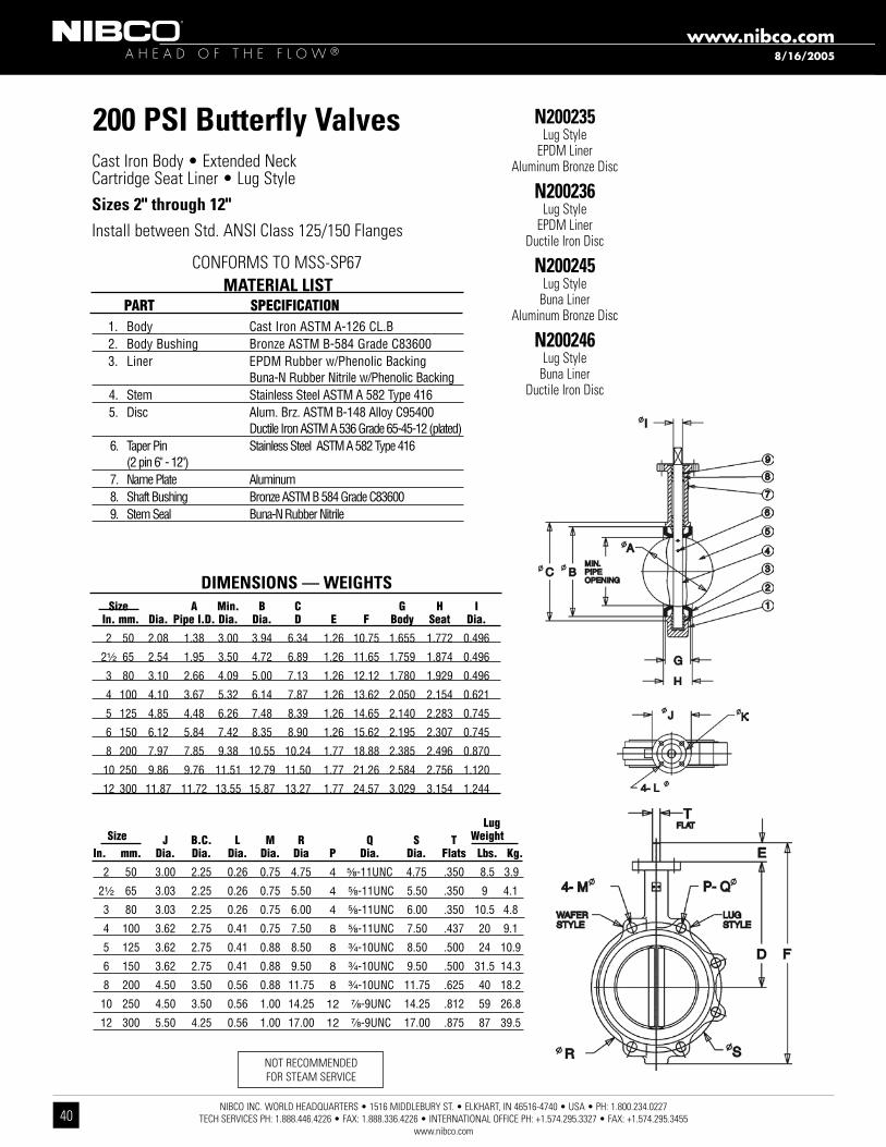
200 PSI Butterfly Valves Cast Iron Body • Extended Neck Cartridge Seat Liner • Lug StyleSizes 2" through 12"Install between Std. ANSI Class 125/150 Flanges
1. Body Cast Iron ASTM A-126 CL.B 2. Body Bushing Bronze ASTM B-584 Grade C83600 3. Liner EPDM Rubber w/Phenolic Backing Buna-N Rubber Nitrile w/Phenolic Backing 4. Stem Stainless Steel ASTM A 582 Type 416 5. Disc Alum. Brz. ASTM B-148 Alloy C95400 Ductile Iron ASTM A 536 Grade 65-45-12 (plated) 6. Taper Pin Stainless Steel ASTM A 582 Type 416 (2 pin 6" - 12") 7. Name Plate Aluminum 8. Shaft Bushing Bronze ASTM B 584 Grade C83600 9. Stem Seal Buna-N Rubber Nitrile
MATERIAL LIST Part SPecification
N200235Lug Style
EPDM Liner Aluminum Bronze Disc
N200236Lug Style
EPDM Liner Ductile Iron Disc
N200245Lug Style
Buna Liner Aluminum Bronze Disc
N200246Lug Style
Buna Liner Ductile Iron Disc
Lug Size J B.c. L M r Q S t Weight in. mm. Dia. Dia. Dia. Dia. Dia P Dia. Dia. flats Lbs. Kg.
2 50 3.00 2.25 0.26 0.75 4.75 4 ⁵⁄₈-11UNC 4.75 .350 8.5 3.9
2¹⁄₂ 65 3.03 2.25 0.26 0.75 5.50 4 ⁵⁄₈-11UNC 5.50 .350 9 4.1
3 80 3.03 2.25 0.26 0.75 6.00 4 ⁵⁄₈-11UNC 6.00 .350 10.5 4.8
4 100 3.62 2.75 0.41 0.75 7.50 8 ⁵⁄₈-11UNC 7.50 .437 20 9.1
5 125 3.62 2.75 0.41 0.88 8.50 8 ³⁄₄-10UNC 8.50 .500 24 10.9
6 150 3.62 2.75 0.41 0.88 9.50 8 ³⁄₄-10UNC 9.50 .500 31.5 14.3
8 200 4.50 3.50 0.56 0.88 11.75 8 ³⁄₄-10UNC 11.75 .625 40 18.2
10 250 4.50 3.50 0.56 1.00 14.25 12 ⁷⁄₈-9UNC 14.25 .812 59 26.8
12 300 5.50 4.25 0.56 1.00 17.00 12 ⁷⁄₈-9UNC 17.00 .875 87 39.5
DIMENSIONS — WEIGHTS Size a Min. B c G H i in. mm. Dia. Pipe i.D. Dia. Dia. D e f Body Seat Dia.
2 50 2.08 1.38 3.00 3.94 6.34 1.26 10.75 1.655 1.772 0.496
2¹⁄₂ 65 2.54 1.95 3.50 4.72 6.89 1.26 11.65 1.759 1.874 0.496
3 80 3.10 2.66 4.09 5.00 7.13 1.26 12.12 1.780 1.929 0.496
4 100 4.10 3.67 5.32 6.14 7.87 1.26 13.62 2.050 2.154 0.621
5 125 4.85 4.48 6.26 7.48 8.39 1.26 14.65 2.140 2.283 0.745
6 150 6.12 5.84 7.42 8.35 8.90 1.26 15.62 2.195 2.307 0.745
8 200 7.97 7.85 9.38 10.55 10.24 1.77 18.88 2.385 2.496 0.870
10 250 9.86 9.76 11.51 12.79 11.50 1.77 21.26 2.584 2.756 1.120
12 300 11.87 11.72 13.55 15.87 13.27 1.77 24.57 3.029 3.154 1.244
CONFORMS TO MSS-SP67
NOT RECOMMENDED FOR STEAM SERVICE
8/16/2005
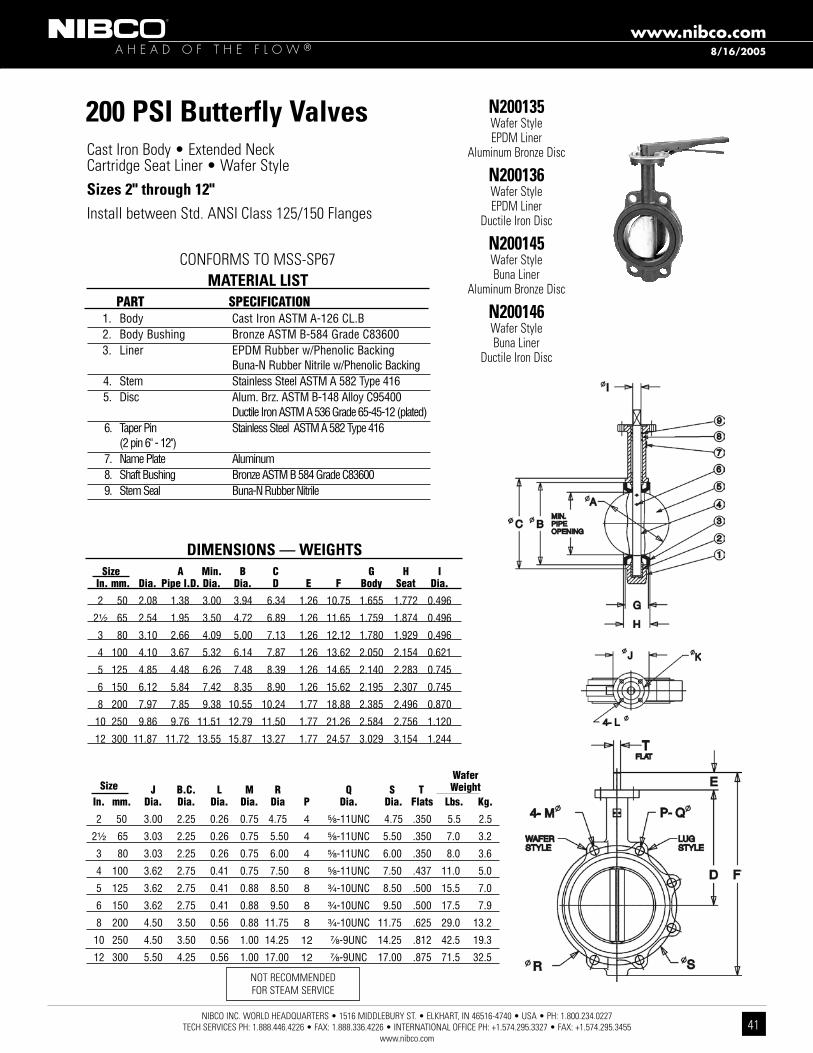
NIBCO INC. WORLD HEADQUARTERS • 1516 MIDDLEBURY ST. • ELKHART, IN 46516-4740 • USA • PH: 1.800.234.0227 TECH SERVICES PH: 1.888.446.4226 • FAX: 1.888.336.4226 • INTERNATIONAL OFFICE PH: +1.574.295.3327 • FAX: +1.574.295.3455
www.nibco.com
A H E A D O F T H E F L O W ®www.nibco.com
41
200 PSI Butterfly Valves Cast Iron Body • Extended Neck Cartridge Seat Liner • Wafer StyleSizes 2" through 12"Install between Std. ANSI Class 125/150 Flanges
1. Body Cast Iron ASTM A-126 CL.B 2. Body Bushing Bronze ASTM B-584 Grade C83600 3. Liner EPDM Rubber w/Phenolic Backing Buna-N Rubber Nitrile w/Phenolic Backing 4. Stem Stainless Steel ASTM A 582 Type 416 5. Disc Alum. Brz. ASTM B-148 Alloy C95400 Ductile Iron ASTM A 536 Grade 65-45-12 (plated) 6. Taper Pin Stainless Steel ASTM A 582 Type 416 (2 pin 6" - 12") 7. Name Plate Aluminum 8. Shaft Bushing Bronze ASTM B 584 Grade C83600 9. Stem Seal Buna-N Rubber Nitrile
MATERIAL LIST Part SPecification
N200135Wafer StyleEPDM Liner
Aluminum Bronze Disc
N200136Wafer StyleEPDM Liner
Ductile Iron Disc
N200145Wafer StyleBuna Liner
Aluminum Bronze Disc
N200146Wafer StyleBuna Liner
Ductile Iron Disc
DIMENSIONS — WEIGHTS Size a Min. B c G H i in. mm. Dia. Pipe i.D. Dia. Dia. D e f Body Seat Dia.
2 50 2.08 1.38 3.00 3.94 6.34 1.26 10.75 1.655 1.772 0.496
2¹⁄₂ 65 2.54 1.95 3.50 4.72 6.89 1.26 11.65 1.759 1.874 0.496
3 80 3.10 2.66 4.09 5.00 7.13 1.26 12.12 1.780 1.929 0.496
4 100 4.10 3.67 5.32 6.14 7.87 1.26 13.62 2.050 2.154 0.621
5 125 4.85 4.48 6.26 7.48 8.39 1.26 14.65 2.140 2.283 0.745
6 150 6.12 5.84 7.42 8.35 8.90 1.26 15.62 2.195 2.307 0.745
8 200 7.97 7.85 9.38 10.55 10.24 1.77 18.88 2.385 2.496 0.870
10 250 9.86 9.76 11.51 12.79 11.50 1.77 21.26 2.584 2.756 1.120
12 300 11.87 11.72 13.55 15.87 13.27 1.77 24.57 3.029 3.154 1.244
CONFORMS TO MSS-SP67
NOT RECOMMENDED FOR STEAM SERVICE
Wafer Size J B.c. L M r Q S t Weight in. mm. Dia. Dia. Dia. Dia. Dia P Dia. Dia. flats Lbs. Kg.
2 50 3.00 2.25 0.26 0.75 4.75 4 ⁵⁄₈-11UNC 4.75 .350 5.5 2.5
2¹⁄₂ 65 3.03 2.25 0.26 0.75 5.50 4 ⁵⁄₈-11UNC 5.50 .350 7.0 3.2
3 80 3.03 2.25 0.26 0.75 6.00 4 ⁵⁄₈-11UNC 6.00 .350 8.0 3.6
4 100 3.62 2.75 0.41 0.75 7.50 8 ⁵⁄₈-11UNC 7.50 .437 11.0 5.0
5 125 3.62 2.75 0.41 0.88 8.50 8 ³⁄₄-10UNC 8.50 .500 15.5 7.0
6 150 3.62 2.75 0.41 0.88 9.50 8 ³⁄₄-10UNC 9.50 .500 17.5 7.9
8 200 4.50 3.50 0.56 0.88 11.75 8 ³⁄₄-10UNC 11.75 .625 29.0 13.2
10 250 4.50 3.50 0.56 1.00 14.25 12 ⁷⁄₈-9UNC 14.25 .812 42.5 19.3
12 300 5.50 4.25 0.56 1.00 17.00 12 ⁷⁄₈-9UNC 17.00 .875 71.5 32.5
8/16/2005

NIBCO INC. WORLD HEADQUARTERS • 1516 MIDDLEBURY ST. • ELKHART, IN 46516-4740 • USA • PH: 1.800.234.0227 TECH SERVICES PH: 1.888.446.4226 • FAX: 1.888.336.4226 • INTERNATIONAL OFFICE PH: +1.574.295.3327 • FAX: +1.574.295.3455
www.nibco.com
A H E A D O F T H E F L O W ®www.nibco.com
42
Bronze Valve Options and AccessoriesHandles
Malleable Iron Malleable
Available for 125, 150, 200, 300 lb. SWP Bronze Body Valves.
Red Bronze 85-5-5-5% ASTM B 62 Lockshield Key
Available for some NIBCO 125 lb. SWP Bronze Body Valves thru 4". Used as handle for lockshields.Specify: ”Lockshield Key.“For field replacement, specify valve type and size. Key available only for valves with spline stems.
Red Bronze 85-5-5-5% ASTM B 62 Bronze
Available for some NIBCO 125 lb. SWP Bronze Body Valves ³⁄₈" thru 2".Used where code requirements or personal preference dictate a bronze handwheel. Specify by adding (BHW) to Fig. No., i.e. T-000-BHW.For field replacement, specify valve type and size.
Red Bronze 85-5-5-5% ASTM B 62 or ASTM B 16 Lockshield Available for some NIBCO 125 lb. SWP Bronze Body Valves thru 4". Use where valve might be subject to unauthorized use or tampering. Specify by adding (L) to Fig. No., i.e. T-000-L. For field replacement, specify valve type and size.
Red Bronze 85-5-5-5% ASTM B 62 Cross
Available for some NIBCO 125 lb. SWP Bronze Body Valves ³⁄₈" thru 3". Use where standard handwheel would be out of reach or hand space is restricted.Specify by adding (K) to Fig. No., i.e. T-000-K.
NIBCO INC. reserves the right to change materials, options and accessories without notice.
6/21/2005
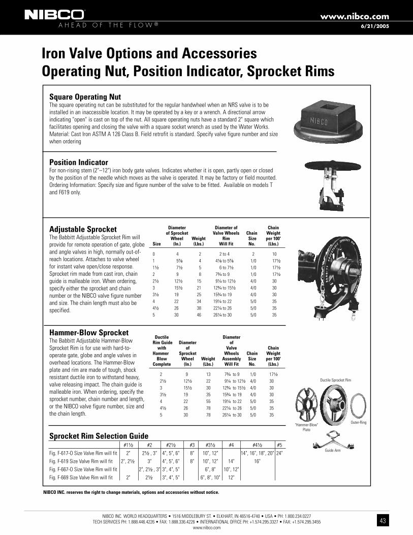
NIBCO INC. WORLD HEADQUARTERS • 1516 MIDDLEBURY ST. • ELKHART, IN 46516-4740 • USA • PH: 1.800.234.0227 TECH SERVICES PH: 1.888.446.4226 • FAX: 1.888.336.4226 • INTERNATIONAL OFFICE PH: +1.574.295.3327 • FAX: +1.574.295.3455
www.nibco.com
A H E A D O F T H E F L O W ®www.nibco.com
43
Iron Valve Options and AccessoriesOperating Nut, Position Indicator, Sprocket Rims
Square Operating NutThe square operating nut can be substituted for the regular handwheel when an NRS valve is to be installed in an inaccessible location. It may be operated by a key or a wrench. A directional arrow indicating "open" is cast on top of the nut. All square operating nuts have a standard 2" square which facilitates opening and closing the valve with a square socket wrench as used by the Water Works. Material: Cast Iron ASTM A 126 Class B. Field retrofit is standard. Specify valve figure number and size when ordering
Position IndicatorFor non-rising stem (2"–12") iron body gate valves. Indicates whether it is open, partly open or closed by the position of the needle which moves as the valve is operated. It may be factory or field mounted.Ordering Information: Specify size and figure number of the valve to be fitted. Available on models T and F619 only.
Adjustable SprocketThe Babbitt Adjustable Sprocket Rim will provide for remote operation of gate, globe and angle valves in high, normally out-of-reach locations. Attaches to valve wheel for instant valve open/close response. Sprocket rim made from cast iron, chain guide is malleable iron. When ordering, specify either the sprocket and chain number or the NIBCO valve figure number and size. The chain length must also be specified.
Hammer-Blow SprocketThe Babbitt Adjustable Hammer-Blow Sprocket Rim is for use with hard-to-operate gate, globe and angle valves in overhead locations. The Hammer-Blow plate and rim are made of tough, shock resistant ductile iron to withstand heavy, valve releasing impact. The chain guide is malleable iron. When ordering, specify the sprocket number, chain number and length, or the NIBCO valve figure number, size and the chain length.
Diameter Diameter of Chain of Sprocket Valve Wheels Chain Weight Wheel Weight Rim Size per 100'Size (In.) (Lbs.) Will fit No. (Lbs.)
0 4 2 2 to 4 2 101 5⁷⁄₈ 4 4¹⁄₈ to 5⁷⁄₈ 1/0 17¹⁄₂
1¹⁄₂ 7¹⁄₂ 5 6 to 7¹⁄₂ 1/0 17¹⁄₂
2 9 8 7³⁄₄ to 9 1/0 17¹⁄₂
2¹⁄₂ 12¹⁄₂ 15 9¹⁄₄ to 12¹⁄₂ 4/0 303 15¹⁄₂ 21 12³⁄₄ to 15¹⁄₂ 4/0 303¹⁄₂ 19 25 15³⁄₄ to 19 4/0 304 22 34 19¹⁄₄ to 22 5/0 354¹⁄₂ 26 38 22¹⁄₄ to 26 5/0 355 30 46 26¹⁄₄ to 30 5/0 35
Ductile Diameter Rim Guide Diameter of with of Valve ChainHammer Sprocket Wheels Chain Weight Blow Wheel Weight Assembly Size per 100' Complete (In.) (Lbs.) Will fit No. (Lbs.)
2 9 13 7³⁄₄ to 9 1/0 17¹⁄₂
2¹⁄₂ 12¹⁄₂ 22 9¹⁄₄ to 12¹⁄₂ 4/0 30 3 15¹⁄₂ 30 12³⁄₄ to 15¹⁄₂ 4/0 30 3¹⁄₂ 19 35 15³⁄₄ to 19 4/0 30 4 22 55 19¹⁄₄ to 22 5/0 35 4¹⁄₂ 26 78 22¹⁄₄ to 26 5/0 35 5 30 78 26¹⁄₄ to 30 5/0 35
Sprocket Rim Selection Guide #1¹⁄₂ #2 #2¹⁄₂ #3 #3¹⁄₂ #4 #4¹⁄₂ #5Fig. F-617-O Size Valve Rim will fit 2" 2¹⁄₂", 3" 4", 5", 6" 8" 10", 12" 14", 16", 18", 20" 24"Fig. F-619 Size Valve Rim will fit 2", 2¹⁄₂" 3" 4", 5", 6" 8" 10", 12" 14" 16" Fig. F-667-O Size Valve Rim will fit 2", 2¹⁄₂", 3" 3", 4", 5" 6", 8" 10", 12" Fig. F-669 Size Valve Rim will fit 2" 2¹⁄₂" 3", 4", 5" 6", 8", 10" 12"
Ductile Sprocket Rim
Guide Arm
Outer-Ring"Hammer-Blow"
Plate
NIBCO INC. reserves the right to change materials, options and accessories without notice.
6/21/2005
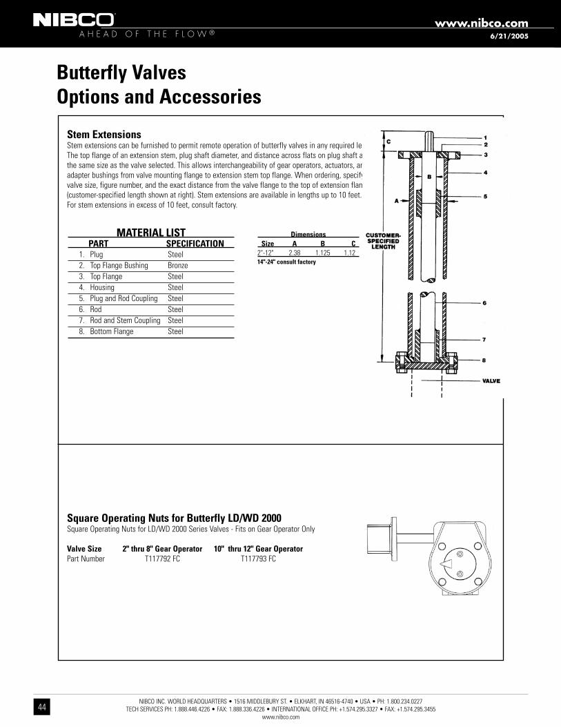
NIBCO INC. WORLD HEADQUARTERS • 1516 MIDDLEBURY ST. • ELKHART, IN 46516-4740 • USA • PH: 1.800.234.0227 TECH SERVICES PH: 1.888.446.4226 • FAX: 1.888.336.4226 • INTERNATIONAL OFFICE PH: +1.574.295.3327 • FAX: +1.574.295.3455
www.nibco.com
A H E A D O F T H E F L O W ®www.nibco.com
44
Stem ExtensionsStem extensions can be furnished to permit remote operation of butterfly valves in any required length. The top flange of an extension stem, plug shaft diameter, and distance across flats on plug shaft are the same size as the valve selected. This allows interchangeability of gear operators, actuators, and adapter bushings from valve mounting flange to extension stem top flange. When ordering, specify valve size, figure number, and the exact distance from the valve flange to the top of extension flange (customer-specified length shown at right). Stem extensions are available in lengths up to 10 feet. For stem extensions in excess of 10 feet, consult factory.
Butterfly ValvesOptions and Accessories
MATERIAL LIST PART SPECIfICATION 1. Plug Steel 2. Top Flange Bushing Bronze 3. Top Flange Steel 4. Housing Steel 5. Plug and Rod Coupling Steel 6. Rod Steel 7. Rod and Stem Coupling Steel 8. Bottom Flange Steel
Dimensions Size A B C2"-12" 2.38 1.125 1.1214"-24" consult factory
Square Operating Nuts for Butterfly LD/WD 2000Square Operating Nuts for LD/WD 2000 Series Valves - Fits on Gear Operator Only
Valve Size 2" thru 8" Gear Operator 10" thru 12" Gear OperatorPart Number T117792 FC T117793 FC
6/21/2005

NIBCO INC. WORLD HEADQUARTERS • 1516 MIDDLEBURY ST. • ELKHART, IN 46516-4740 • USA • PH: 1.800.234.0227 TECH SERVICES PH: 1.888.446.4226 • FAX: 1.888.336.4226 • INTERNATIONAL OFFICE PH: +1.574.295.3327 • FAX: +1.574.295.3455
www.nibco.com
A H E A D O F T H E F L O W ®www.nibco.com
45
Golf Course Service SpecificationsThe Golf Course industry requirements for strong, sturdy maintenance-free valves are critical to the operation of the Golf Course. Corrosion is a real concern for many irrigation installations and high quality valves are the best solution for flow isolation in irrigation piping systems. NIBCO valves use optimum materials to protect the valves from failure due to corrosion or dezincification, problems often encountered with foreign yellow brass.
Isolation Valves 3" and SmallerGate Valves:Non-Rising Stem: Valves shall be class 125 and 200 PSI CWP, non-rising stem, screw-in bonnet, solid wedge and USA produced in accordance with MSS SP-80. Body, bonnet, external stuffing box and wedge are to be of Bronze ASTM B 62. Stems shall be of dezincification-resistant silicon Bronze ASTM B 371 or low-zinc alloy B 99, non-asbestos packing and malleable or ductile iron handwheel. For buried service —Bronze Cross or Bronze handwheel required. Valve ends shall be threaded type.
Acceptable Valves:200 PSI CWP NIBCO T-113-K (Bronze Cross H/W) (³⁄₄" thru 3")200 PSI CWP NIBCO T-113-BHW (Bronze H/W) (¹⁄₄" thru 3")200 PSI CWP NIBCO T-113 (MI H/W) (¹⁄₄" thru 3")
Globe/Angle Valves:Valves shall be Class 125 and 200 PSI CWP, body and bonnet are to be of Bronze ASTM B 62 and USA produced in accordance with MSS SP-80. Stems shall be of dezincification-resistant Silicon Bronze ASTM B 371 or Low-Zinc Alloy B 99, non-asbestos packing, PTFE seat disc and malleable or ductile iron handwheel. For buried service — Bronze Cross handwheel required. Valve ends shall be threaded type.
Acceptable Valves:200 PSI CWP NIBCO globe/angle T-211-YK/T-311-YK (Bronze Cross H/W) (1" thru 2")200 PSI CWP NIBCO globe/angle T-211-Y/T-311-Y (MI H/W) (¹⁄₄" thru 3")
Ball Valves:Valves shall be Class 150 and 600 PSI non-shock CWP and USA produced in accordance with MSS SP-110. Two-piece cast bronze bodies, PTFE seats, full port or reduced port on 2¹⁄₂" and 3", separate packnut with adjustable stem packing, anti-blowout stems. Stainless steel ball, handle and nut or chrome plated ball and steel handle. Valve ends shall have full depth ANSI threads.
Acceptable Valves – full Port:Class 150 NIBCO T-580-70-66 (SS ball and handle) (¹⁄₄"" thru 2")Class 150 NIBCO T-585-70 (Chrome plated ball and steel handle) (¹⁄₄" thru 2")
Acceptable Valves – Reduced Port:Class 150 NIBCO T-580-70-66 (SS ball and handle (2¹⁄₂" and 3")Class 150 NIBCO T-580-70 (Chrome plated ball and steel handle) (2¹⁄₂" and 3")
Isolation Valves 2" and largerGate Valves:Non-Rising Stem:Resilient Wedge Design: Valves shall be 200 PSI CWP and USA produced, valve body and bonnet designed and tested to meet AWWA C 509. Body and bonnet are to be of Cast Iron Alloy ASTM A 126 Class B or Ductile Iron ASTM A 536. Valve to be epoxy coated inside and outside. Two upper O-ring stem seals. Sealed counter sunk body bonnet bolts providing no exposure of bonnet bolts. Stems to be stainless steel. Resilient rubber encapsulated wedge. Cast iron 2" square operating nut. Valve ends shall be IPS PVC push-on joint, flanged-type or mechanical joint-type.
Acceptable Valves:
6/21/2005

NIBCO INC. WORLD HEADQUARTERS • 1516 MIDDLEBURY ST. • ELKHART, IN 46516-4740 • USA • PH: 1.800.234.0227 TECH SERVICES PH: 1.888.446.4226 • FAX: 1.888.336.4226 • INTERNATIONAL OFFICE PH: +1.574.295.3327 • FAX: +1.574.295.3455
www.nibco.com
A H E A D O F T H E F L O W ®www.nibco.com
46
Golf Course Service Specifications200 PSI CWP NIBCO P-619-RW (IPS PVC push-on) (2" thru 12")200 PSI CWP NIBCO F-619-RW (Flanged) (2" thru 16")200 PSI CWP NIBCO MJ-619-RW (Mechanical joint) (2" thru 16")200 PSI CWP NIBCO FM-619-RW (Flanged by mechanical joint) (2" thru 12")
IBBM Design: Valves to be Class 125 and 200 PSI CWP and USA produced in accordance with MSS SP-70. Bolted bonnet, bronze trimmed, with body and bonnet conforming to ASTM A 126 Class B cast iron. Packing and gaskets to be non-asbestos. Valve ends shall be flanged-type.
Acceptable Valves:200 PSI CWP NIBCO F-619 (Cast iron H/W) (2" thru 16")200 PSI CWP NIBCO F-619-SON (2" Square operating nut) (2" thru 16")
Butterfly Valves:Valve shall be 200 PSI CWP (2" thru 12") and 150 PSI CWP (14" and larger) and USA produced in accordance with MSS SP-67. Body to have 2" extended neck and to be cast iron or ductile iron. Valve to have aluminum bronze alloy disc with EPDM rubber seat and seals; or EPDM rub-ber encapsulated disc with polymer-coated body. Stem shall be 400 series stainless steel and shall not have exposed stem to disc fasteners. Sizes 2 1/2" thru 6" shall be lever-operated with 10-position throttling plate; sizes 8" and larger shall have gear operators. Lug-style, flanged and grooved style shall be capable for use as isolation valves and recommended by manufacturer for dead-end service at full pressure— without the need of downstream flanges. Valve ends shall be lug, wafer, flanged or I.P.S. grooved body style.
Acceptable Valves:200 PSI CWP Lug body, aluminum bronze disc NIBCO LD/WD-2000-3 (lever operator); LD/WD-2000-5 (gear operator) (2" thru 24")200 PSI CWP Flanged body, rubber coated disc NIBCO FC-2765-3 (lever operator); FC-2765-5 (gear operator) (2" thru 12")300 PSI CWP Grooved body, rubber coated disc NIBCO GD-4765-3 (lever operator); GD-4765-5 (gear operator) (2" thru 12")
Check Valves for Backflow 3" and SmallerCheck Valves:Valves shall be Class 125 and 200 PSI CWP and USA produced in accordance with MSS SP-80, body shall be bronze ASTM B 62 body with PTFE seat disc, Y-pattern swing type or stainless steel spring loaded center guided lift-type with PTFE seating. Valve ends shall be threaded type.
Acceptable Valves:200 PSI CWP NIBCO T-413-Y (Swing Type) (1/4" thru 2"); NIBCO T-433-Y (Swing Type) (2 1/2" and 3")200 PSI CWP NIBCO T-480-Y (Center Guided) (3/8" thru 2")
Check Valves for Backflow 2" and LargerCheck Valves:Valves shall be Class 125 and 200 PSI CWP and USA produced in accordance with MSS SP-71, bolted bonnet, bronze trimmed, with body and bonnet conforming to ASTM A 126 Class B cast iron, gasket to be non-asbestos, swing type. Or, valves shall be Class 125 and 200 PSI CWP and USA manufactured in accordance with FM, bronze trim, with body and bonnet conforming to ASTM A 48 cast iron, stainless steel spring-loaded center-guided globe-style lift-type. Valve ends shall be flanged type or wafer type.
Acceptable Valves:200 PSI CWP NIBCO F-918-B (Flanged, swing type) (2" thru 12")200 PSI CWP NIBCO F-910-B (Flanged, center guided) (2" thru 36")200 PSI CWP NIBCO W-910-B (Wafer, center guided) (2" thru 10")
6/21/2005

NIBCO INC. WORLD HEADQUARTERS • 1516 MIDDLEBURY ST. • ELKHART, IN 46516-4740 • USA • PH: 1.800.234.0227 TECH SERVICES PH: 1.888.446.4226 • FAX: 1.888.336.4226 • INTERNATIONAL OFFICE PH: +1.574.295.3327 • FAX: +1.574.295.3455
www.nibco.com
A H E A D O F T H E F L O W ®www.nibco.com
47
Valve flow Data
Throttling factorsFor throttling use with disc partially open. Multiply Cv by factor.
Percent Open 0 10 20 30 40 50 60 70 80 90 100T-211/311 0 .35 .65 .90 .93 .96 .98 .99 1.00 1.00 1.00
Ball and Butterfly Valves Degrees of OpenT-580 0 .01 .05 .16 .30 .37 .45 .58 .71 .87 1.00T-580-70 0 .01 .05 .16 .30 .37 .45 .58 .71 .87 1.00T-585-70 0 .01 .05 .16 .30 .37 .45 .58 .71 .87 1.00LD/WD 2000 0 .03 .06 .12 .18 .22 .27 .40 .56 .80 1.00
Warning
The fluid flow factors contained herein are calculated values. They are therefore approximations and cannot be used for highly critical flow or pressure drop calculations.
for very precise flow measurements, tests must be conducted on any valve mentioned within this catalog.
flow DataCv Values for Valves
Valve SizeFigure Nos. ¹⁄₈" ¹⁄₄" ³⁄₈" ¹⁄₂" ³⁄₄" 1" 1¹⁄₄" 1¹⁄₂" 2" 2¹⁄₂" 3" 4" 5" 6" 8" 10" 12" 16"GatesT-113 5.6 10.7 17.6 32 54 97 135 230 337 536 960 1525 2250 T/F-619 215 335 510 945 1525 2250 4150 6700 9925 18375
GlobesT-211/311 0.61 1.16 2.21 3.64 6.65 11.1 20 28 48 70 111
ChecksT-413 (swing) 1.3 2.5 4.8 14.3 24 43 60 102 150 238 465T-480 (poppet) 3.7 6.86 16.3 30 49 72 130F-918 (swing) 150 243 356 665 1073 1584 2937 4730 6985W-910 (poppet) 500 806 1200 2200 3550 5250
BallT-580 5.8 13.9 27 44 64 100T-580-70 38.5 76 101.4 183 390T-585-70 4.2 6.2 15.3 30.4 48.8 103 143 245
ButterflyLD/WD 2000 166 247 340 660 1080 1613 3759 5300 7969
6/21/2005

A H E A D O F T H E F L O W®www.nibco.com
NIBCO INC. WORLD HEADQUARTERS • 1516 MIDDLEBURY ST. • ELKHART, IN 46516-4740 • USA • PH: 1.800.234.0227 TECH SERVICES PH: 1.888.446.4226 • FAX: 1.888.234.0557 • INTERNATIONAL OFFICE PH: +1.574.295.3327 • FAX: +1.574.295.3455
www.nibco.com
48
Revision 6/4/08
Properties of Valve Materials
otHer ManGa- MoLYB- aStM aLLoY carBon cHroMe coBaLt coPPer iron LeaD neSe DenUM aLLoY no. DeSiGnation aL c cr co cu fe Pb Mn Mo
Commercial Aluminum 380 SC 84 A UNS A38000 87.0 1.0 1.3 .35 (modified)
Free Cutting Brass B 16 UNS C36000 61.5 3.0
Navy "M" (Steam Bronze) B 61 UNS C92200 .005 88.0 .25 1.5
Composition Bronze (Ounce Metal) B 62 UNS C83600 .005 85.0 .30 5.0
Copper-Silicon Alloy B B 98/B 99 UNS C65100 96.0 .8 .05 .7
Forging Brass B 124 UNS C37700 60.0 .3 2.0
Forging Brass B 283 UNS C37700 58.0 .3 2.5
Brass Wire (Red Brass) B 134 UNS C23000 85.0 .05 .05
Leaded Red Brass B 140 UNS C31400 89.0 .10 1.9
Aluminum Bronze (Cast) B 148 UNS C95400 11.0 85.0 4.0
Aluminum Bronze (Rod) B 150 UNS C64200 7.0 91.0 .30 .05 .10
Silicon Red Brass B 371 UNS C69400 81.5 .20 .30
Leaded Semi-Red Brass B 584 UNS C84400 .005 81.0 .40 7.0
Leaded Red Brass UNS C84500 .005 78.0 .40 7.0
Leaded Nickel Bronze B 584 UNS C97600 64.0 4.0
Copper (Wrot) B 75 UNS C12200 99.9
Gray Iron A 126 Class B
3% Ni Gray Iron A 126 Class B (modified)
Austenitic Gray Iron (Ni-Resist) A 436 Type 2 3.00 2.0 .5 1.0
Ductile Iron (Ferritic) A 395 3.20
Austenitic Ductile Iron (Ductile) A 536 65-45-12 (Ductile) A 536 80-55-06 (Ni-Resist) A 439 D2C 2.9 .5 2.4 1.0
noMinaL or MaxiMUM cHeMicaL coMPoSition
Iron
Cop
per
Bro
nze
& B
rass

A H E A D O F T H E F L O W®www.nibco.com
NIBCO INC. WORLD HEADQUARTERS • 1516 MIDDLEBURY ST. • ELKHART, IN 46516-4740 • USA • PH: 1.800.234.0227 TECH SERVICES PH: 1.888.446.4226 • FAX: 1.888.234.0557 • INTERNATIONAL OFFICE PH: +1.574.295.3327 • FAX: +1.574.295.3455
www.nibco.com49
titan- tUnG- tenSiLe YieLD nicKeL PHoS SiLicon SULfUr tin iUM Sten zinc StrenGtH StrenGtH % ni P Si S Sn ti W zn Psi Psi eLonGation HarDneSS
.50 12.0 .15 .50 42,000 19,000 3.5
35.5 50,000 20,000 15 75 HRB
65 HB 1.0 .05 .005 .05 6.0 4.5 34,000 16,000 22 *500 kg
60 HB 1.0 .05 .005 .08 5.0 5.0 30,000 14,000 20 500 kg
1.6 1.5 86,000** 20,000 11 65 HRB
38.0 52,000 20,000 45 80 HRB
38.0 52,000 20,000 45 78 HRB
15.0 56,000 60 HRB
.7 9.1 50,000 30,000 7 60 HRB
170 HB 75,000 30,000 12 *3000 kg
.25 2.0 .20 .50 90,000 45,000 9 80 HRB
4.0 14.5 80,000 40,000 15 85 HRB
55 HB .02 .005 .08 3.0 9.0 29,000 13,000 18 *500 kg
55 HB 1.0 .02 .005 .08 3.0 12.0 29,000 13,000 16 *500 kg
20.0 4.0 8.0 40,000 17,000 10 80 HB
.02 36,000 30,000 25 45 T
.75 .15 31,000 195 HB
3.00 .75 .15 31,000 195 HB
20.0 2.0 .12 25,000 118 HB
.08 2.50 60,000 40,000 18 167 HB
.08 2.50 65,000 45,000 12 160 HB .08 2.50 80,000 55,000 6 160 HB 24.0 .08 3.0 58,000 28,000 20 146 HB
*Load Applied During Testing **Allowable Range is 75,000 to 95,000
noMinaL or MaxiMUM cHeMicaL coMPoSition noMinaL PHYSicaL ProPertieS
Revision 6/4/08
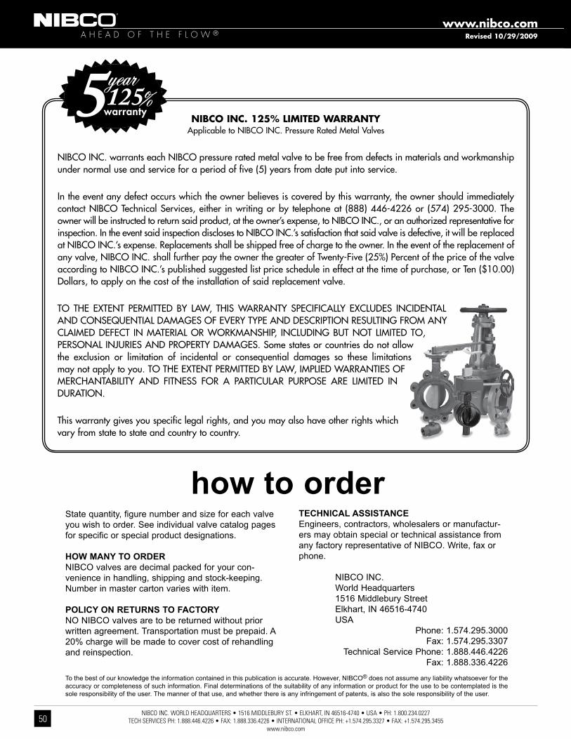
NIBCO INC. WORLD HEADQUARTERS • 1516 MIDDLEBURY ST. • ELKHART, IN 46516-4740 • USA • PH: 1.800.234.0227 TECH SERVICES PH: 1.888.446.4226 • FAX: 1.888.336.4226 • INTERNATIONAL OFFICE PH: +1.574.295.3327 • FAX: +1.574.295.3455
www.nibco.com
A H E A D O F T H E F L O W ®www.nibco.com
50
State quantity, figure number and size for each valve you wish to order. See individual valve catalog pages for specific or special product designations.
HOW MANY TO ORDER NiBco valves are decimal packed for your con-venience in handling, shipping and stock-keeping. Number in master carton varies with item.
POLICY ON RETURNS TO FACTORY No NiBco valves are to be returned without prior written agreement. transportation must be prepaid. a 20% charge will be made to cover cost of rehandling and reinspection.
TECHNICAL ASSISTANCE engineers, contractors, wholesalers or manufactur-ers may obtain special or technical assistance from any factory representative of NiBco. Write, fax or phone.
NiBco iNc. World Headquarters 1516 middlebury Street elkhart, iN 46516-4740 USa Phone: 1.574.295.3000 fax: 1.574.295.3307 technical Service Phone: 1.888.446.4226 fax: 1.888.336.4226
to the best of our knowledge the information contained in this publication is accurate. However, NiBco® does not assume any liability whatsoever for the accuracy or completeness of such information. final determinations of the suitability of any information or product for the use to be contemplated is the sole responsibility of the user. the manner of that use, and whether there is any infringement of patents, is also the sole responsibility of the user.
how to order
Revised 10/29/2009
NIBCO INC. 125% LIMITED WARRANTYApplicable to NIBCO INC. Pressure Rated Metal Valves
NIBCO INC. warrants each NIBCO pressure rated metal valve to be free from defects in materials and workmanship under normal use and service for a period of five (5) years from date put into service.
In the event any defect occurs which the owner believes is covered by this warranty, the owner should immediately contact NIBCO Technical Services, either in writing or by telephone at (888) 446-4226 or (574) 295-3000. The owner will be instructed to return said product, at the owner’s expense, to NIBCO INC., or an authorized representative for inspection. In the event said inspection discloses to NIBCO INC.’s satisfaction that said valve is defective, it will be replaced at NIBCO INC.’s expense. Replacements shall be shipped free of charge to the owner. In the event of the replacement of any valve, NIBCO INC. shall further pay the owner the greater of Twenty-Five (25%) Percent of the price of the valve according to NIBCO INC.’s published suggested list price schedule in effect at the time of purchase, or Ten ($10.00) Dollars, to apply on the cost of the installation of said replacement valve.
TO THE EXTENT PERMITTED BY LAW, THIS WARRANTY SPECIFICALLY EXCLUDES INCIDENTAL AND CONSEQUENTIAL DAMAGES OF EVERY TYPE AND DESCRIPTION RESULTING FROM ANY CLAIMED DEFECT IN MATERIAL OR WORKMANSHIP, INCLUDING BUT NOT LIMITED TO, PERSONAL INJURIES AND PROPERTY DAMAGES. Some states or countries do not allow the exclusion or limitation of incidental or consequential damages so these limitations may not apply to you. TO THE EXTENT PERMITTED BY LAW, IMPLIED WARRANTIES OF MERCHANTABILITY AND FITNESS FOR A PARTICULAR PURPOSE ARE LIMITED IN DURATION.
This warranty gives you specific legal rights, and you may also have other rights which vary from state to state and country to country.

NIBCO INC. WORLD HEADQUARTERS • 1516 MIDDLEBURY ST. • ELKHART, IN 46516-4740 • USA • PH: 1.800.234.0227 TECH SERVICES PH:1.888.446.4226 • FAX: 1.888.336.4226 • INTERNATIONAL OFFICE PH: +1.574.295.3327 • FAX: +1.574.295.3455
www.nibco.com
It’s a new age of
business, and a new
way at NIBCO. From
Elkhart, Indiana to
Lodz, Poland, and
points beyond,
our company has
integrated manufacturing,
distribution, and networked
communications to provide
a seamless source of
information and service, 24
hours a day, 7 days a week.
But this integration hasn’t
happened overnight. It’s been
part of a long-term strategic
process that has pushed us
to reconsider every aspect
of our business. The result?
We’re a vertically integrated
manufacturer with the
products and systems in
place to deliver low cost
and high quality. NIBCO®
products are manufactured
under a Quality Management
System conforming to the
current revision of ISO-9001
International Standards. We
know the flow control industry
is only going to get more
demanding, and we are more
than ready. We will continue
to lead. That’s what NIBCO is
all about.
globally connecting you at all levels
World Headquarters
Elkhart, Indiana
Metal Valves and Fittings
Blytheville, Arkansas
McAllen, Texas
Nacogdoches, Texas
Stuarts Draft, Virginia
Plastic Pipe, Valves, and Fittings
Greensboro, Georgia
Goshen, Indiana
Lebanon,Ohio
Industrial Plastics
Charlestown, Indiana
International
Reynosa, Mexico
Lodz, Poland
U.S. Distribution Centers
Elkhart, Indiana
Global Offices
Elkhart, Indiana
Lodz, Poland
M A N U FA C T U R I N G D I S T R I B U T I O N I N T E R N AT I O N A L
* * *
*
*
*
*Denotes U.S. and International Direct Shipping Locations
*

C-IRR -0805 © 2005 NIBCO INC., Al l R ights Reser ved Pr in ted in U.S.A.
C-IRR-0805
N I B C O I N C .
W O R L D H E A D Q U A R T E R S
W E B : w w w. n i b c o . c o m
1516 M IDD L EBURY S T R E E T
E L KHART, IN 46516 -4740
USA
D O M E S T I C C U S T O M E R S E R V I C E
P H O N E : 8 0 0 . 2 3 4 . 0 2 2 7
FA X : 8 0 0 . 2 3 4 . 0 5 5 7
T E C H N I C A L S E R V I C E
P H O N E : 8 8 8 . 4 4 6 . 4 2 2 6
FA X : 8 8 8 . 3 3 6 . 4 2 2 6
I N T E R N AT I O N A L O F F I C E
P H O N E : + 1 / 5 7 4 . 2 9 5 . 3 3 2 7
FA X : + 1 / 5 7 4 . 2 9 5 . 3 4 5 5
F E AT U R I N G N I BCO® SYSTEMSNIBCO® PEX Piping Systems • NIBCO® Press System®
CHEMTROL®
Thermoplastic pipe, valves and fittings in PVC, Corzan® CPVC, polypropylene and PVDF Kynar® • Pneumatic and electric actuation systems
Corzan® is a registered trademark of The Lubrizol Corporation. • Kynar® is a registered trademark of Arkema Inc.
F I T T I N G SWrot and cast copper pressure and drainage fittings • Cast copper alloy flanges • Wrot and cast press fittings • ABS and PVC DWV fittings • Schedule 40 PVC pressure fittings • CPVC CTS fittings • CPVC CTS- to -metal transition fittings • Schedule 80 PVC and CPVC systems • CPVC metric piping systems • CPVC BlazeMaster® fire protection fittings • Lead-Free* fittingsBlazeMaster® is a registered trademark of The Lubrizol Corporation.*Weighted average lead content 0.25%
eNIBCOEDI—Electronic Data Interchange • VMI—Vendor Managed Inventory • NIBCO.com • NIBCOpartner.com
VALVES & ACTUATIONPressure-rated bronze, iron and alloy-iron gate, globe and check valves • Pressure-rated bronze ball valves • Boiler specialty valves • Commercial and industrial butterfly valves • Circuit balancing valves • Carbon and stainless steel ball valves • ANSI flanged steel ball valves • Pneumatic and electric actuators and controls • Grooved ball and butterfly valves • High performance butterfly valves • UL/FM fire protection valves • MSS specification valves • Bronze specialty valves • Low pressure gate, globe, check and ball valves • Frostproof sillcocks • Quarter--turn supply stops • Quarter-turn low pressure valves • PVC ball valves • CPVC CTS ball valves • Just Right® recirculating valves • Bronze & Iron Y-Strainers • Lead-Free* valves*Weighted average lead content 0.25%