ahts project
TRANSCRIPT

ANCHOR HANDLING TUG SUPPLY VESSEL (AHTS)
Surya chala Praveen doddugolluRegd NO: 309106918009Under The Guidance OfDr. T.v.k.bhanuprakashPROFESSOR
DEPARTMENT OF MARINE ENGINEERINGCOLLEGE OF ENGINEERINGANDHRA UNIVERSITYVISAKHAPATNAM2009-2013

GENERAL DESCRIPTION
AHTS vessels have superior bollard pull and a higher engine rating (BHP).
They are fitted with a combination of multiple thrusters (Bow and Stern)with twin-screw CPP systems (can work in any sea condition).
Large amount of strengthened deck required at space astern of the accommodation areas.
AHTS have an extremely powerful multi-drum system catering twin winches, one each for towing and anchor handling purposes.
Required larger capacity of rig chian locker.
OTHER FEATURES:
AHTS are multipurpose vessels, perform the duties of the ordinary supply boats such as carrying large quantity of water, fuel and deck cargo.
Carries cement, dry bulk, liquid mud etc. Can be used as fire fighting vessel. Installation of buoys, sub-sea moorings are
ideally done with the assistance of the Anchor Handling Tugs.

OWNERS REQUIREMENT:
Type of ship: anchor handling tug supply vessel
Dead weight: 2500tonnes Speed : 15knots Crew : 40members Class : DNV(det norske veristar) Propulsion : azipod type propulsion with
diesel electric propulsion system.
Vessel should be fitted withDP2 system. Type of bow: Inverted bow (X-bow).
ESTIMATION OF MAIN DIMENSIONS:
The first step of the design is to start with the fixing of main dimension which done on the basis of parent vessels.
The basic dimensions of the vessel are arrived upon using the statistical approach on the existing parent ships.
In correspondence to the given owners requirements the data is collected for the ships of existing fleet which fall in similar category of given problem statement.
ESTIMATED MAIN PARTICULARS:
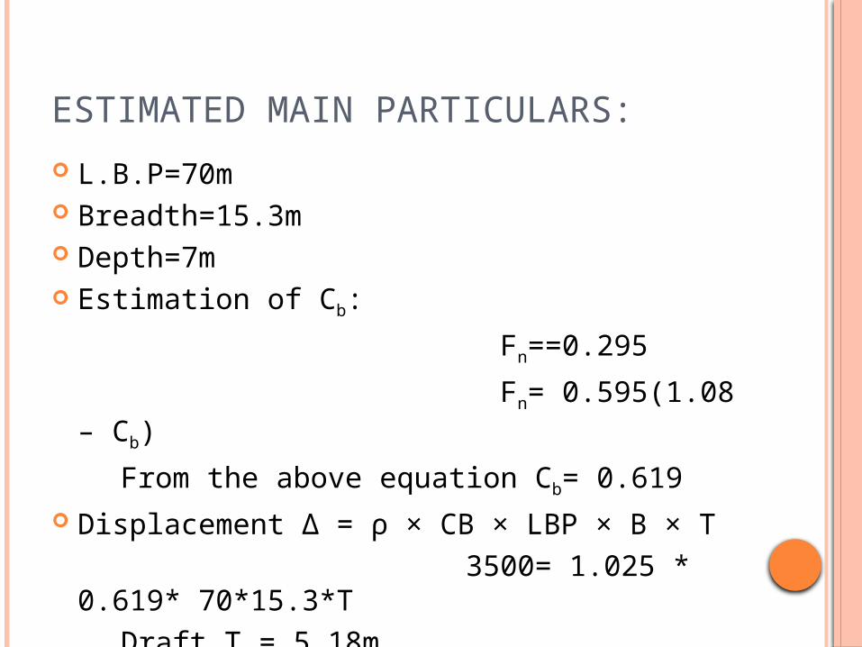
L.B.P=70m Breadth=15.3m Depth=7m Estimation of Cb:
Fn==0.295
Fn= 0.595(1.08 – Cb)
From the above equation Cb= 0.619 Displacement Δ = ρ × CB × LBP × B × T 3500= 1.025 * 0.619*
70*15.3*T Draft T = 5.18m

HULL FORM DESIGN & LINES PLAN
When the principal dimensions, displacement and form-coefficient are known, one has an impressive amount of design information, but not yet a clear image of the exact geometrical shape of the ship.
This can be obtained by the use of edge curves.
PREPARING OF EDGE CURVES USING RHINOCEROS SOFTWARE:
Stem profile. Stern profile. Flat of bottom. Deck contour. Flat of side. By using above contours we can
prepare hull surface.

INVERTED BOW:
It is a newly invented bow. Larger and higher volume distribution Less spray Slender hull lines Safer workplace due to increased protection
provided by hull.

Optimized hull shape The shape of the hull has been optimized with
a view to high top speeds, low resistance and reduced fuel consumption.
Comfort Elimination of slamming and bow impact Soft entry in waves Low acceleration levels Reduced vibration levels Available crew rest time increased Safer workplace due to smoother motions

HULL FORM IN RHINOCEROS:


BODY PLAN:
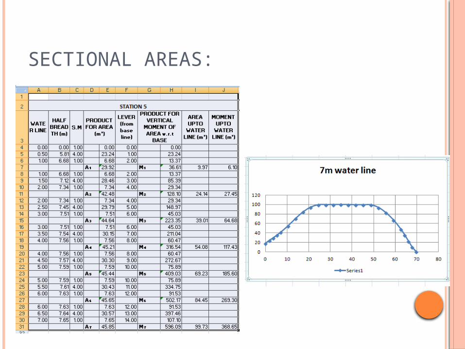
SECTIONAL AREAS:

BONJEAN CURVE:
Lentgh of the ship
Are
as
at
each
sect
ion

HYDROSTATIC PROPERTIES:

INTACT STABILITY CALCULATIONS
The stability characteristics of a vessel are depicted with the help of Cross Curves of Stability and Curves of Statical Stability.
Cross curves of stability:

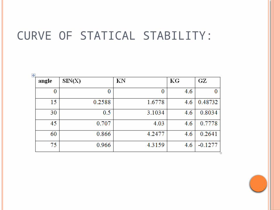
CURVE OF STATICAL STABILITY:

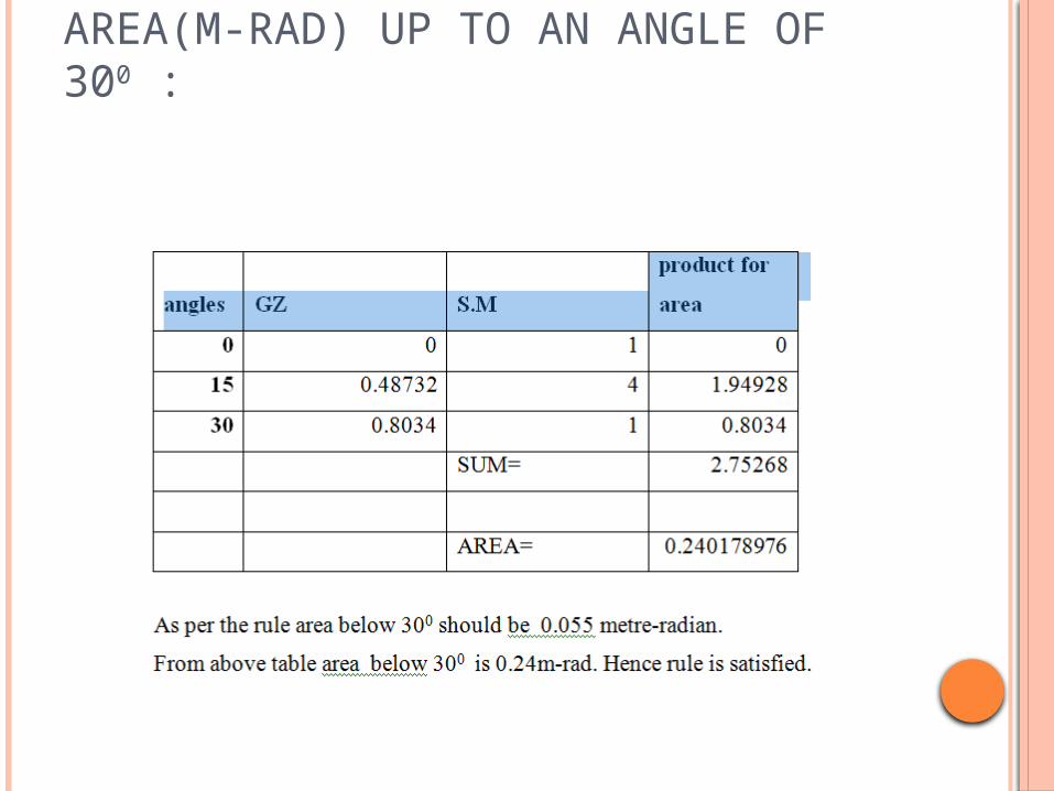
AREA(M-RAD) UP TO AN ANGLE OF 300 :

As per the rule area under GZ curve between angle of heels 300 and 400 should be greater than 0.03 m-rad.
From the graph area is 0.1387m-rad which is greater than 0.03 m-rad.
As per the rule 0.09 mrad up to an angle of 400 or the angle at which the lower edges of any openings in the hull, superstructure or deckhouses, being openings which cannot be closed weather tight, become immersed if that angle is less.
Area under GZ curve between angle of heels 00 and 400 = 0.3788m-rad.

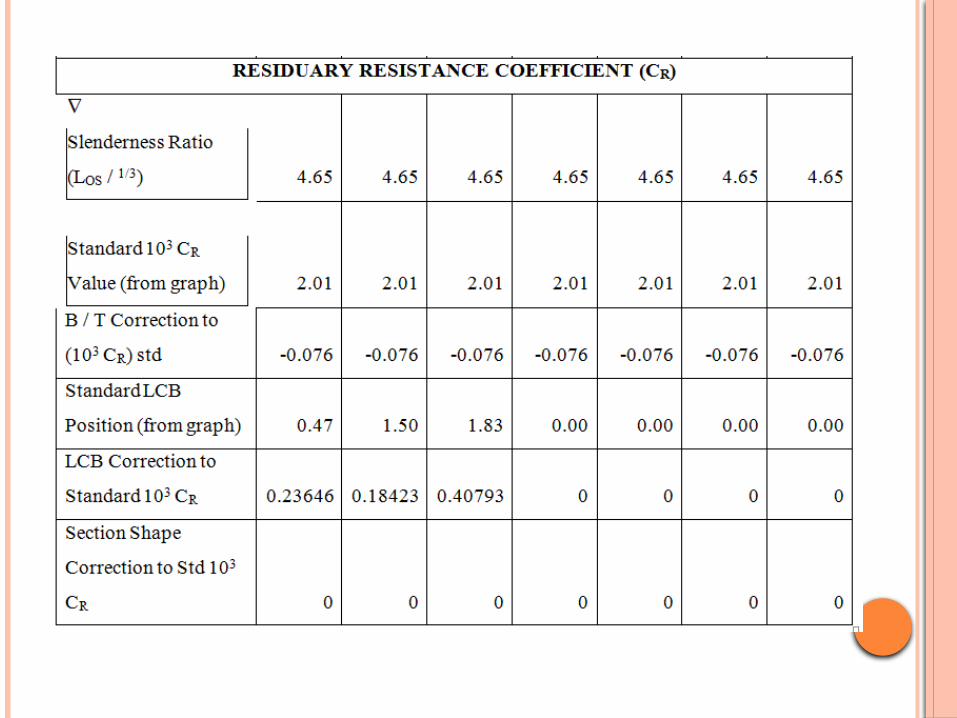
RESISTANCE CALCULATIONS(USING GULDHAMMER AND HARVALD METHOD)
The total resistance coefficient of the ship CT = CF +CR +CA
Where CF = Frictional resistance coefficient.
CR = Residual resistance coefficient
CA= Incremental resistance coefficient
CF will be calculated using ITTC formula,and by adding some corrections to it.
CR will be calculated from THE CHARTS PUBLISHED BY GULDHAMMER & HARVALD corrections has to be done.

CALCULATIONS OF INCREMENTAL RESISTANCE COEFFICIENT CA :
This is for corrections to roughness surface and scale effect on the Results for model experiments and it will depend on CF and CR. This incremental coefficient for model ship correlation as a speed. More recent experiments have given correction for roughness and scale effects.
Air and steering resistance: Air resistance 10 3 CAA = 0.07
Steering resistance 10 3 CAS = 0.04
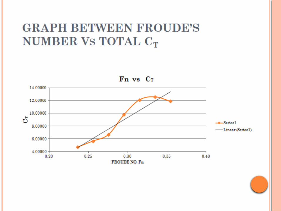
TOTAL RESISTANCE COEFFICIENT : CT = CR + CF + CA + CAA +CAS
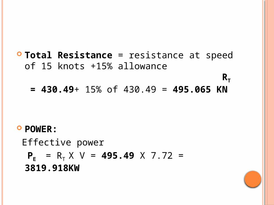
Total Resistance = resistance at speed of 15 knots +15% allowance RT = 430.49+ 15% of 430.49 = 495.065 KN
POWER: Effective power PE = RT X V = 495.49 X 7.72 =
3819.918KW


GENERAL ARRANGEMENT:
The first step in solving the general arrangement problems of a cargo ship is locating the main spaces and their boundaries within the ship hull and superstructure.
These spaces are: 1. Cargo tanks 2. Machinery spaces 3. Crew, passenger and associated
spaces 4. Tanks (Double Bottom tanks, After Peak
Tank, and Fore Peak Tank) 5. Miscellaneous
Frame spacing: 0.48 + 0.002 L= 0.6192m In between collision bulk head and 0.2L
from F.P. the frame spacing is 700[mm] or (1) whichever is less.

BULKHEAD REQUIREMENTS: For ships without longitudinal bulkheads in
the cargo region, the total number of watertight transverse bulkheads is normally not to be less than given in Table A1.

THRUSTERS: Bow thruster: 1x 800 hp tunnel, electrically driven,
Thrust: 8.80 t. Bow thruster: 1x 1,200 hp, diesel driven, thrust: 13.20
t. Stern thruster: 1x 800 hp tunnel, electrically driven,
Thrust: 8.80 t. TOWING/ANCHOR HANDLING WINCH: Main winches: 1 waterfall BRATTVAAG SL 400WB/SL
400W. - 2 drums: 3,600 m of 3” wire, with spooling device,
each. - Cable lifters: For 3”3/4 chain (each). - Brake holding load: 1st layer A/H and towing drums:
600 t. - Duty in hoist: 1st layer A/H and towing drums: - Low gear: 400 t at 0-9 m/min — High gear: 200 t at 0-
18 min.
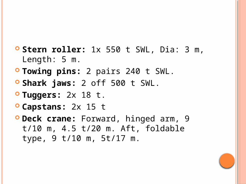
Stern roller: 1x 550 t SWL, Dia: 3 m, Length: 5 m.
Towing pins: 2 pairs 240 t SWL. Shark jaws: 2 off 500 t SWL. Tuggers: 2x 18 t. Capstans: 2x 15 t Deck crane: Forward, hinged arm, 9 t/10 m,
4.5 t/20 m. Aft, foldable type, 9 t/10 m, 5t/17 m.
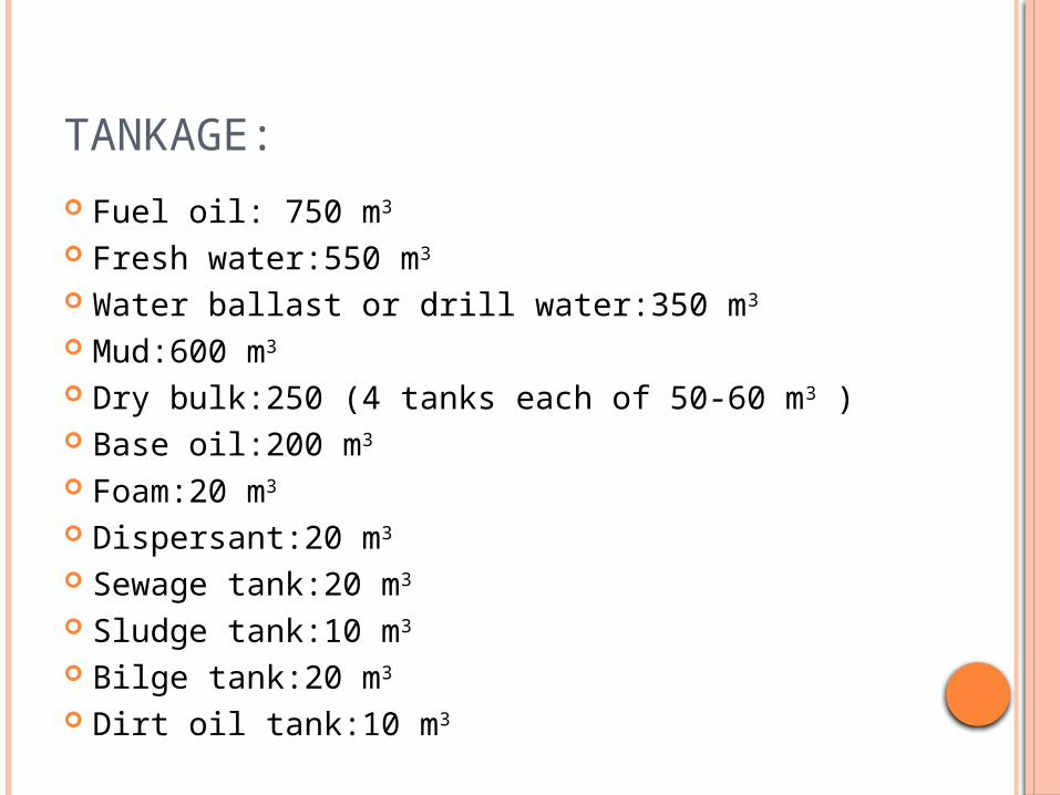
TANKAGE:
Fuel oil: 750 m3
Fresh water:550 m3
Water ballast or drill water:350 m3
Mud:600 m3
Dry bulk:250 (4 tanks each of 50-60 m3 ) Base oil:200 m3
Foam:20 m3
Dispersant:20 m3
Sewage tank:20 m3
Sludge tank:10 m3
Bilge tank:20 m3
Dirt oil tank:10 m3
THANK YOU