aicarr journal · aicarr journal 2015, 32, 68-75bis research paper 1 co 2 heat pump combined with...
TRANSCRIPT

AiCARR Journal 2015, 32, 68-75bis
Research paper
1
CO2 HEAT PUMP COMBINED WITH HIGH TEMPERATURE
DIFFERENCE HEATING TERMINAL UNITS: PERFORMANCE
OPTIMIZATION ACCORDING TO AN INTELLIGENT MANAGEMENT
Nicolandrea Calabrese1, Raniero Trinchieri1, Paola Rovella2, Cecilia Piazzolla3, Michele Vio4, Marco Pozzati5, Luca Scalambrin5
1 UTTEI-TERM Laboratory, ENEA Casaccia Research Center, Rome 2 DIMEG Department, University of Calabria, Cosenza 3 University Roma Tre, Rome 4Freelance Engineer, Venice 5IRSAP SpA – Arquà Polesine, Rovigo
ABSTRACT
An efficient solution for the retrofit of existing buildings, generally equipped with traditional boiler and heating terminal units, is represented by heat pumps that use CO2 (R744) as refrigerant and the adoption of an innovative electronic thermostatic modulating valves for the heating terminal units in order to maximize the machine performances. The CO2 has environmental (ODP=0 and GWP=1) and thermodynamic advantages which make it particularly suitable for the satisfaction of high hot water demands. The experimental tests were carried out with the aim of evaluating the performance of an air to water CO2 heat pump combined to heating terminal units that are characterized by a high temperature difference and equipped with innovative valves. The use of these valves has mainly the purpose of reducing the water temperature at heat pump inlet, because the CO2
heat pump performances decrease with the increasing of this parameter. The tests were performed at different boundary conditions and the results have allowed to determine the effect of modulating valves on heat pump and gas cooler performances and to identify the improvements to be implemented over the entire system.
Keywords: CO2 heat pump, building retrofit, heating terminal unit, regulation system
Introduction
The Italian building stock consists mainly of existing buildings, often of historic value, whose construction is before the emanation of laws and decrees about energy saving and efficiency; in these buildings the production of energy for heating and domestic hot water is generally realized by a traditional boiler powered by fossil fuel and combined with heating terminal units. For the retrofit of these buildings, an
efficient and minimally invasive solution is represented by the replacing of traditional boiler with heat pump systems that uses CO2 (R744) as refrigerant and the adoption of an innovative system of electronic regulation in order to maximize the performance of the machine. Compared to traditional refrigerants, the CO2 has advantages both environmental and of design and plant engineering, which make it

N. Calabrese et al.: CO2 heat pump combined with high temperature difference heating terminal units
2
particularly suitable for the production of water at high temperature, especially for the high demands satisfaction of hot water, and for winter heating also in climates more stringent, ensuring defrost phases of short duration. The experiments described in this article were carried out at UTTEI-TERM laboratory of ENEA Casaccia Research Center (Rome), with the aim of evaluating the performance of an air to water CO2 heat pump (electric compression system) combined to heating terminal units that are characterized by a high temperature difference and equipped with electronic thermostatic modulating valves. The use of this innovative and intelligent control system, managed with wireless technology, has mainly the purpose of reducing the water temperature at heat pump inlet, because the CO2 heat pump performances decrease with the increasing of this parameter. The tests were performed at different boundary conditions, with variable values of outside air temperature (from 7 °C up to about -10 °C) and with a temperature difference between heating terminal units inlet and outlet equal to about 30 °C. The experimental results have allowed to determine the modulating valves effect on the heat pump performance and on the gas cooler efficiency.
1. The system
The features of the two main components of
the system are briefly explained below: CO2
heat pumps and heating terminal units at high temperature difference.
1.1 CO2 heat pumps
The CO2 heat pumps operation is different from the operation of machines using traditional refrigerants because the phase of thermal energy transfer takes place not by the condensation of CO2 but through its gradual cooling inside the gas cooler in a transcritical cycle; the efficiency of this heat exchanger is strongly dependent on the water temperature at heat pump inlet, that means at the gas cooler (Calabrese et al., 2013; Cecchinato et al., 2005; Neksa, 2002; Rieberer et al., 1997). By way of example, in Figure 1, on the right side, the temperature profile of carbon dioxide and of water are shown: the former is at a pressure of 120 bar, with temperature values at inlet and outlet respectively equal to about 100 °C and 20 °C and the latter presents an increasing temperature from 15 °C up to about 90 °C (in a countercurrent flow). In the same Figure 1, on the left side, the temperature profiles, decidedly less favorable, are shown and they are refer to a condenser of a HFC heat pump: in this case, the temperature differences between the fluids in the various sections of the heat exchanger vary considerably, causing high exergetic losses, and so low efficiencies of heat exchanger and outlet water temperature value considerably lower than the case of CO2.
Figure 1 – Difference between the temperature profiles in a HFC condenser and in a CO2 gas cooler in a heat pump for heating water.

N. Calabrese et al.: CO2 heat pump combined with high temperature difference heating terminal units
3
The use of carbon dioxide has significant benefits of environmental aspects, because the CO2 is non-flammable, non-toxic, it has a zero ODP, a unitary GWP and it respects the Regulation num. 517/2014 EU (European Parliament, 2014) on the phase-down of HFCs. The carbon dioxide thermodynamic properties, an ad hoc design of each components and a special regulation enable the use of air-water heat pumps using CO2 as a refrigerant in situations where the outside air temperature reaches values up to -25 °C (Cavallini, 2004; Kim et al., 2004). Further, the high values of temperature at compression outlet limit negative effects of defrost, reducing its duration, compared to the traditional refrigerants. The CO2 heat pumps are particularly suited to the revamping of heating systems with boilers and heating terminal units, because they are able to produce water at high temperature, above 70 °C, with very high performance if the water temperature of return to the gas cooler is maintained to values lower than 30 °C. It's important that the heating terminal units matched to this machine are dimensioned to work with a
high water temperature difference between the inlet and the outlet, as it’s shown in the comparison between the two thermodynamic cycles reported in Figure 2, referring both to a same air to water heat pump when the air temperature is equal to -3 °C (evaporation temperature of -10 °C) but at different value of water temperature at gas cooler inlet: 40 °C in a) cycle, 25 °C in b) cycle). According to the thermodynamic diagram a), in the blue cycle reported in a) the CO2 at the compressor, in state 1, is in the following conditions T = 124 °C and P = 10 MPa and it is then cooled to the state 2, characterized by a temperature equal to 45 °C. In this configuration, typically of a traditional heating system, the useful effect is limited, as well as the COP which is equal to 2.05. If better values of both the power and efficiency are desired, especially of the power, the only possibility is to further increase the pressure value, bringing it to 11 MPa (cycle in yellow), thus determining an increase of the value of temperature that reaches 134 °C and obtaining an increase of 16% for the efficiency and of 8% for COP; the temperature value of point 2 remains obviously unchanged.
a)
b)
Figure 2 – Thermodynamic cycles for two different water temperatures at gas cooler inlet. The inlet water temperature is equal to 40 °C in case a) and 25 °C in case b). From (Vio, 2013).
N. Calabrese et al.: CO2 heat pump combined with high temperature difference heating terminal units
4
The only possibility to increase both the useful effect and the COP is to make the water temperature at machine inlet lower. In the thermodynamic diagram in b) of Figure 2 it is shown what would happen if the machine were matched with heating terminal units operating with a high temperature difference, able to reduce the inlet temperature up to 25 °C: the value of the optimum supply pressure would decrease to 8 MPa and the COP would rise to 3.24, excellent result if it’s considered that, as mentioned, the outside air temperature in this example is equal to -3 °C. The value of the temperature in state 1 would be reduced to 101 °C and the temperature of the state 2 would drop to 30 °C and the power supplied would be greater by 23% than that of the thermodynamic cycle blue in the diagram reported in a) of figure 2 (Calabrese, 2012).
1.2 The terminal heating units
The heating terminal units are terminal units able to operate with very low water flow rates and high thermal differences. The heating terminal unit power curve, normally given as a function of the difference between ambient temperature and medium temperature of the heat transfer fluid, can be expressed as a
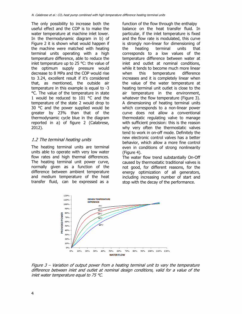
function of the flow through the enthalpy balance on the heat transfer fluid. In particular, if the inlet temperature is fixed and the flow rate is modulated, this curve is strongly non-linear for dimensioning of the heating terminal units that corresponds to a low values of the temperature difference between water at inlet and outlet at nominal conditions, while it tends to become much more linear when this temperature difference increases and it is completely linear when the value of the water temperature at heating terminal unit outlet is close to the air temperature in the environment, whatever the flow temperature (Figure 3). A dimensioning of heating terminal units which corresponds to a non-linear power curve does not allow a conventional thermostatic regulating valve to manage with sufficient precision: this is the reason why very often the thermostatic valves tend to work in on-off mode. Definitely the new electronic control valves has a better behavior, which allow a more fine control even in conditions of strong nonlinearity (Figure 4). The water flow trend substantially On-Off caused by thermostatic traditional valves is not good, for different reasons, for the energy optimization of all generators, including increasing number of start and stop with the decay of the performance.
Figure 3 – Variation of output power from a heating terminal unit to vary the temperature difference between inlet and outlet at nominal design conditions, valid for a value of the inlet water temperature equal to 75 °C.

N. Calabrese et al.: CO2 heat pump combined with high temperature difference heating terminal units
5
Figure 4 – Comparison of water flow distribution in terminal heating unit with high water content in the case of traditional thermostatic valve and in the case of electronic valve.
The variation, as little as possible, of the flow rate during the adjustment is very important because it means that: - the temperature of the return water is as
close as possible to the design value (that is, the optimized value);
- the generator works with greater regularity without continuous start and stop.
These aspects are important whatever the generator, but are fundamental with heat pumps, in particular with those use the CO2 as a refrigerant.
2. Methods
The tests were carried out using a test facility specifically designed, in pre-fixed conditions of air temperature at evaporator inlet and by varying the value of the set point for each
terminal heating element in order to analyze the functioning of the valves and the machine (Calabrese et al., 2014).
2.1 Experimental system
The test facility consists of the following components (Figure 5): - air to water carbon-dioxide heat pump,
(Figure 6); - three terminal heating units of multicolumn
tubular steel type; - a regulation system of the terminal heating
units, consists of modulating valves; - a monitoring and data acquisition system. The terminal heating units are connected in parallel, and they are connected to a single hot collector and one cold collector. The heat pump is a commercial machine for sanitary hot water production, with a nominal heat power of 4.5 kW.
Figure 5 - Test facility with CO2 heat pump with heating terminal units of high temperature difference.
Figure 6 – CO2 heat pump.

N. Calabrese et al.: CO2 heat pump combined with high temperature difference heating terminal units
6
The main components of the machine are
(Figure 7): - a two-stage rotary compressor; - a silencer; - a pressure switch; - a pipe in pipe gas cooler; - an electronic expansion valve whose opening degree can be operated by the control system integrated with the commercial machine or from an external controller; - a finned coil evaporator coupled to an axial fan. Special precautions in the design of the refrigerating circuit allow to achieve an efficient frost protection system for the lower zones of the heat exchanger, thus avoiding the use of electric heaters or to the reversal of the cycle; - a liquid receiver. The heat pump was instrumented with thermocouples of K and J type and pressure sensors to monitor the thermodynamic state of CO2 at (input / output) main components (Figure 7). Monitoring and acquisition of experimental data were made through a
program developed in LabVIEW. The values of temperature and pressure acquired allow to view in real time on the p-h diagram the cycle made by CO2 during the tests. It is possible to vary the working frequency of the compressor with a potentiometer. Two flow sensors were also included to assess the CO2 and water flow in the gas cooler. The air temperature of the environment in which the heating terminal units are placed, Ta, is monitored with three thermocouples, one for each terminal heating unit, each positioned at one meter distance from the centerline of the terminal unit. The heating terminal unit management is realized through the electronic control unit in Figure 8: the rooms to be heated are defined with their set point values of Ta and each heating terminal unit, with its own characteristics, is associated with the room in which it is placed; the electronic control unit, via a Wi-Fi system, communicates with the valves installed on each terminal unit.
Figure 7 - Instrumented heat pump system layout. From (Boccardi, 2012).

N. Calabrese et al.: CO2 heat pump combined with high temperature difference heating terminal units
7
Maximum value of water temperature: 75 °C; Operating temperature range: -5 °C / + 50 °C; Storage Temperature Range: -10 °C / + 65 °C; Antenna integrated in the device; Maximum flow signal in free area: 120 m; Dimensions: 52 mm diameter and 76 mm length.
Figure 8 - Electronic thermostatic modulating valves with Wi-Fi control.
2.2. Modality of experimental test execution
The tests were performed under steady and transient state, in standard (PDC Std) and non-standard (Std PDC NO) operation, the latter achieved using a potentiometer for varying the frequency of the machine compressor. The machine in operation non-standard allows in fact to raise the value of the output pressure from the compressor, obtaining a useful effect greater because on the p-h diagram the thermodynamic cycle of the refrigerant is expanded and moves upwards. To ensure the air temperature values at the evaporator control, the heat pump is located in a box at a controlled temperature.
3. Results
The analysis of the experimental results made it possible to evaluate the overall performance of the machine and the effects of different boundary conditions on both the COP and the efficiency of the gas cooler. The results refer to tests carried out with values of outside air temperature between 7 °C and about -10 °C. The tests were performed using conventional thermostatic valves and electronic modulating valves at different set point values of the air temperature in the environment, in order to evaluate the effect of the innovative valves proposed system on the heat pump operation. The processing of the experimental data allowed to identify improvements to be made to both the machine tested, in particular
to the gas cooler, and the control logic of the heat pump-heating terminal units system in order to maximize the performance of the machine.
3.1 Results about the overall operation and machine and gas cooler performances
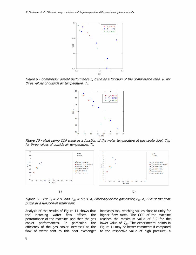
About the compressor performance, the experimental results have shown that this installed component ensures high performances in any condition of operation. The compressor global efficiency values relative to the tests carried out with electronic valves for outside air temperature in the range -14 °C and -10 °C are shown in Figure 9. It is clear that the efficiency reaches values between 0.55 and 0.69, assuming acceptable values for unfavorable boundary conditions, that is very low values of outside air temperature, Te. The heat pump COP trend is shown in Figure 10 as a function of the water temperature at gas cooler inlet, TiW, for values of Te between -14 °C and -10 °C. The COP values are between 1.75 and 2.3, very acceptable for the conditions of considered outside air temperature. Tests carried out with conventional thermostatic valves have been carried out for different values of the supply water temperature to the terminal system (40 °C, 50 °C and 60 °C), and for a value of Te equal to 7 °C. The experimental results about the case of TuW equal to 60 °C are shown in Figure 11.
N. Calabrese et al.: CO2 heat pump combined with high temperature difference heating terminal units
8
0.55
0.6
0.65
0.7
3.5 4 4.5 5 5.5
Te = -14 [°C]
Te = -11 [°C]
Te = -10 [°C]
ηg[-
]β [-]
Figure 9 - Compressor overall performance ηg trend as a function of the compression ratio, β, for three values of outside air temperature, Te.
Figure 10 - Heat pump COP trend as a function of the water temperature at gas cooler inlet, TiW, for three values of outside air temperature, Te.
a) b)
Figure 11 - For Te = 7 °C and TuW = 60 °C a) Efficiency of the gas cooler, εgc, b) COP of the heat pump as a function-of water flow.
Analysis of the results of Figure 11 shows that the incoming water flow affects the performance of the machine, and then the gas cooler performances. In particular, the efficiency of the gas cooler increases as the flow of water sent to this heat exchanger
increases too, reaching values close to unity for higher flow rates. The COP of the machine reaches the maximum value of 3.2 for the lower value of TiW. The experimental points in Figure 11 may be better comments if compared to the respective value of high pressure, a

N. Calabrese et al.: CO2 heat pump combined with high temperature difference heating terminal units
9
parameter that strongly determines both the efficiency εgc and the COP. This aspect has been left out because not very relevant to the objectives of this work. In tests carried out with TuW = 60 °C, for flow rates equal to about 60 kg/h and for operation in standard mode, the efficiency of the gas cooler is lower than that which occurs in non-standard operating mode (frequency of the compressor controlled by potentiometer) and the difference between the temperature values of carbon dioxide and water on the cold side of the gas cooler never be zero, even in case TiW takes values comparable with those of TuW. The experimental data relating to the conventional thermostatic valves use have shown clearly that the performances of the CO2
heat pump are very influenced by the water flow, and its increasing caused the increasing of gas cooler efficiency. The efficiency of the gas cooler trend is reported in Figure 12 as a function of the difference of temperature on the cold side of the heat exchanger, ∆TGC, cs, that is, the difference between the CO2 temperature at gas cooler outlet and the water temperature at gas cooler inlet. These experimental points refer to low values of the outdoor air temperature (-14 °C <Te <-10 °C). From Figure 12 it is shown that when ∆TGC, cs increases, the efficiency of the gas cooler becomes worse. To better investigate the effect of the water flow will be necessary to conduct other tests.
Figure 12 - Efficiency of the gas cooler, ɛgc, as a function of the temperature difference between the temperature of CO2 at gas cooler outlet and the water temperature at gas cooler inlet.
It is evident that the CO2 heat pump has good overall performance for low values of outside air temperature and this is also due to the use of a two stage compressor, which allows to develop high compression ratios for low values of the temperature of cold source and / or for high values of the hot source
3.2 Results related to the operation with electronic modulating valves installed on heating terminal units combined with the heat pump
In order to characterize the operation of electronic modulating valves, the set point of the air temperature in the environment in which
the heating terminal units are placed were varied, using the Wi-Fi control unit in Figure 8. The Figure 13 shows the results relating to the tests carried out at 40 °C. The arrows in the figure indicate the set point changes of the air temperature in the room associated to heating terminal units (ST1, ST2 and ST3). According Figure 13, refer to TuW = 40 °C, the value of ∆TGC, cs is maintained constant during static conditions and varies with the set point on the valves, since the optimum water flow rate in the gas cooler is bigger and close to the optimality conditions. The loss of control occurs only when all the valves work with a very low set point and the required power tends to be zero. Note that the tests were carried out at

N. Calabrese et al.: CO2 heat pump combined with high temperature difference heating terminal units
10
a)
b)
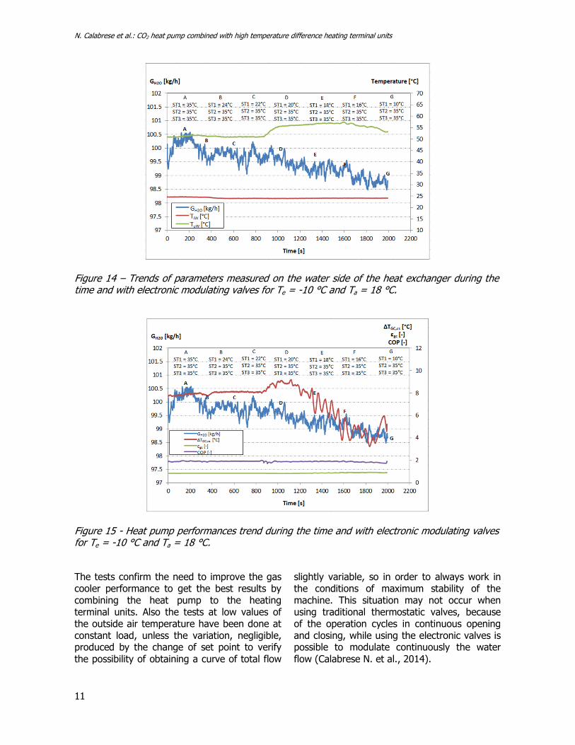
Figure 13 - Test with electronic modulating valves: a) Te = 7 °C, TuW = 40 °C; b): Te = 7 °C, TuW = 40 °C. constant load, unless the variation, negligible, due to the change of the set point. The Figures 14 and 15 are about the test carried out in conditions of air temperature equal to -10 °C and air temperature in the environment in which are placed the heating terminal units equal to 18 °C. Initially the set-point temperature of the air in the room was set at 35 °C on all heating terminal units, to obtain the complete opening of all three valves, and then the set point of the temperature relative to a single heating terminal unit was varied. From Figure 14, where the trend of different parameters are reported as a function of the time and they refer to the water side of the exchanger, it is clear that during the first part of the test the difference between the temperature values at the inlet and at the outlet of the heating terminal units has remained equal to about 30 °C. In the diagram of Figure 15, as a function of the time, the trends of water flow, the efficiency of the gas cooler, the COP and the difference between the CO2 temperature at gas cooler outlet and water
temperature at gas cooler inlet are reported. The letters indicate the moments when the set point of the air temperature in the environment associated with each heating terminal units were changed (ST1, ST2 and ST3). As can be seen, the water flow and the efficiency of the gas cooler are substantially stable, while the value of ∆TGC, cs (difference between the CO2 temperature at gas cooler outlet and the water temperature at gas cooler inlet) varies a lot in the second part of the test. The decrease of water flow due to electronic valves causes an increase of the value of TuW at equal TiW. This obviously has an impact on all the operation parameters of the heat pump and in particular on the evaporation temperature, on the flow rate of CO2 and on the compression ratio. In Figures 16 and 17 the results of the test carried out with values of temperature of the outdoor air and air of the environments, in which the heating terminal units are placed, equal to respectively -11 °C and 19 °C are reported.
N. Calabrese et al.: CO2 heat pump combined with high temperature difference heating terminal units
11
Figure 14 – Trends of parameters measured on the water side of the heat exchanger during the time and with electronic modulating valves for Te = -10 °C and Ta = 18 °C.
Figure 15 - Heat pump performances trend during the time and with electronic modulating valves for Te = -10 °C and Ta = 18 °C.
The tests confirm the need to improve the gas cooler performance to get the best results by combining the heat pump to the heating terminal units. Also the tests at low values of the outside air temperature have been done at constant load, unless the variation, negligible, produced by the change of set point to verify the possibility of obtaining a curve of total flow
slightly variable, so in order to always work in the conditions of maximum stability of the machine. This situation may not occur when using traditional thermostatic valves, because of the operation cycles in continuous opening and closing, while using the electronic valves is possible to modulate continuously the water flow (Calabrese N. et al., 2014).

N. Calabrese et al.: CO2 heat pump combined with high temperature difference heating terminal units
12
Figure 16 - Trends of parameters measured on the water side of the heat exchanger during the time for Te = -11 °C and Ta = 19 °C and with electronic modulating valves.
Figure 17 – Heat pump performances trend during the time and with electronic modulating valves for Te= -11 °C e Ta=19 °C and with electronic modulating valves.
3.3 Potentiality and evolution of the CO2 heat pump combined with a heating terminal units
The operation of the CO2 heat pumps is strongly influenced by the value of the water temperature at gas cooler inlet, whereby these heat pumps can be used only in a circuit with variable flow, which can ensure the constancy of the return temperature as the load varies. This choice involves additional problems
because, as it was shown, the efficiency of the gas cooler used is optimized only in a certain flow range. It is possible to think of machines specifically designed for heating systems, with appropriate solutions to make the optimum water flow range larger, for example with two gas coolers in parallel, intercepted by refrigerator and hydraulic side; however, the flow oscillations must be fairly limited, if performances must be high.

N. Calabrese et al.: CO2 heat pump combined with high temperature difference heating terminal units
13
To custom algorithms for single heating terminal unit and to the ability to communicate with the generator in order to indicate the most suitable production temperature value, must be added additional functions such as the ability to control also the value of the temperature at the outlet, while the entire system has to calculate the return flow rate and adapt the value of the production temperature so that the flow rate variation range is limited. The supervisory system must also dialogue with a water flow meter at the inlet of the heat pump and the associated gas cooler. The operating logic must be such that the temperature of the produced water must be fixed on the basis of both the opening of the valves and the total flow in the gas cooler, so as to optimize the COP. The plant must be calculated considering a high value of the temperature difference between input and output of the heating terminal units (for example 48 °C, with T = 70°C as input and T = 22 °C as output) so to linearize the power output curve as a function of flow rate, to make management with electronic valves easier. At constant boundary conditions, compared to thermostatic valves, the electronic valves are able to maintain constant the value of the average water temperature at gas cooler inlet and close to that of the ambient air temperature. Also the temperature of the produced water by the heat pump is lower in the case of electronic valves (provided that the management logic is appropriately designed). Finally, in the case of electronic valves the machine has a COP always higher than that is obtained with the use of conventional thermostatic valves due to low production temperature, the lower number of start and stop per hour of the generator and the water flow optimization at the gas cooler.
4. Conclusions
The CO2 heat pumps could be generators particularly suitable in combination with heating systems with heating terminal units with a high temperature difference. The conditional is necessary because currently the only models on the market are those designed for sanitary hot water production. Research has shown that heating systems,
especially those with heating terminal units, can work with low temperature of the water returning to the generator: a correct sizing of the heating terminal units and the plant allow a value of return water temperature of only a couple of Celsius degrees lower than the environment air temperature, even in full load conditions. For the success of the project, however, it’s necessary to pay special attention to several aspects. First, the heating terminal units must have a high water content, of at least 10 ÷ 15 liters per kW of rated power (maximum operating conditions) so as to allow slow variations of the temperature profile inside them, ensure to the plant an inertia such as to enable a few starts of the heat pump compressor, ensure in all conditions a value of the water temperature at heating terminal units outlet close to the air temperature, and allow a good management using the electronic thermostatic valves. It can be said that the heating terminal units with high water content are the best ever terminals for CO2 heat pumps, significantly better than radiant systems that have an high thermal inertia. This last aspect is essential: a sufficiently low value of the water temperature at heating terminals outlet, and then incoming into the gas cooler, can only be achieved with a variable water flow circuit, with a setting that allows a continuous modulation. The CO2 heat pumps therefore need regulation devices specially studied. The control system with electronic valves allows to manage and optimize the value of the water flow and inlet temperature at the gas cooler, as well as that of the environment air temperature and temperature of water produced to be sent to the plant. This aspect is fundamental for the achievement of sufficient energy efficiency. A CO2 heat pump optimized for a heating system should work with flow of water sufficiently low, which would require a substantial redesign of the gas cooler used here and probably the adoption of particular solutions, such as two heat exchangers in parallel, to be optimized in any condition of operation. In addition, the performances of CO2 heat pumps are significantly better than those of traditional heat pumps for low values of outside air temperature, resulting in lower power consumption, especially in the most critical conditions, or start at the morning.

N. Calabrese et al.: CO2 heat pump combined with high temperature difference heating terminal units
14
Symbols
COP GCO2 GH2O Ta Te TiW TuW ∆TGS,cs
coefficient of performance, dimensionless CO2 mass flow rate, kg/s Water mass flow rate, kg/h Environment air temperature, °C External air temperature, °C Water temperature at heat pump inlet, °C Water temperature at heat pump outlet, °C Temperature difference between CO2 temperature at gas cooler outlet and water temperature at gas cooler inlet (at gas cooler cold side), °C
Greek symbols ɛgc
ηg
gas cooler efficiency, dimensionless compressor global efficiency, dimensionless
References
Boccardi G., Calabrese N., Saraceno L., Trinchieri R. 2012.
Realizzazione di un prototipo di macchina frigorifera caldo
freddo dedicata al settore alimentare. ENEA RdS/2012/128.
Roma: ENEA.
Calabrese C. 2012. Pompe di calore e impianti a heating
terminal uniti, Aicarr Journal, 12, 36-43.
Calabrese N., Lattanzi A., Trinchieri R. Rovella P., Piazzolla
C., Vio M., Pozzati M., Scalambrin L. 2014. Studio teorico-
sperimentale sull’ottimizzazione del funzionamento di
pompe di calore a CO2 (R744) con heating terminal uniti ad
elevato salto termico. ENEA Report RdS/Par2013/166.
Roma: ENEA.
Cavallini A. 2004. Properties of CO2 as refrigerant.
Proceedings of European Seminar Carbon dioxide as a
refrigerant. Milano: Centro Studi Galileo.
Cecchinato L., Corradi M., Fornasieri E., Zamboni L. 2005.
Carbon dioxide as refrigerant for tap water heat pumps: a
comparison with the traditional solution. International
Journal of Refrigeration, 28, 1250-1258.
Kim M., Pettersen J., Bullard C. W. 2004. Fundamental
process and system design issues in CO2 vapor compression
systems. Progress in Energy and Combustion Science, 30(2),
119-174.
Neksa P. 2002. CO2 heat pump systems. International
Journal of Refrigeration, 25, 421-427.
Parlamento Europeo. 2014. Regolamento (UE) N. 517/2014
del Parlamento Europeo e del Consiglio del 16 aprile 2014
sui gas fluorurati a effetto serra e che abroga il regolamento
(CE) n. 842/2006. Gazzetta ufficiale dell’Unione europea L
150/195 del 20.05.2014.
Rieberer R., Kasper G., Halozan J. 1997. CO2 - A Chance
For Once Through Heat Pump Heaters. CO2 Technology in
Refrigeration, Heat Pumps and Air Conditioning Systems,
IEA Heat Pump Centre Trondheim Norway, 1997.
Vio M. 2013. La pompa di calore nel retrofit di edifici
esistenti con impianti a heating terminal uniti. Atti Convegno
AiCARR, Padova
.