aiiad ahmad m. al beshri thesis (pdf 3mb) - qut eprints
TRANSCRIPT

Outsourcing Data Storage without OutsourcingTrust in Cloud Computing
by
Aiiad A. Albeshri
Bachelor of Science (Computer Science), KAU, Saudi Arabia – 2002Master of Information Technology (QUT) – 2007
Thesis submitted in accordance with the regulations forDegree of Doctor of Philosophy
School of Electrical Engineering and Computer Science
Science and Engineering Faculty
Queensland University of Technology
July 2013


Keywords
Cloud Computing, Cloud Security, Cloud Storage, Cloud Storage Se-curity, Geographic Assurance, Data Replication, Trust in the Cloud
i

ii

Abstract
Cloud computing has emerged as a major ICT trend and has been acknowledged
as a key theme of industry by prominent ICT organisations. This new paradigm
delivers a large pool of virtual and dynamically scalable resources, including com-
putational power, storage, hardware platforms and applications, to users via In-
ternet technologies. Examples of these benefits include increases in flexibility and
budgetary savings through minimisation of hardware and software investments.
It would appear that cloud customers are enthusiastic about being allowed
to store their data in the cloud but at the same time they want personal satis-
faction and the comfort of checking for themselves (or through a trusted third
party) that their data is protected. The main theme of this thesis is to allow the
users of the cloud services to outsource their data without the need to trust the
cloud provider. Specifically, cloud customers will be able to verify the confiden-
tiality, integrity, availability, fairness (or mutual non-repudiation), data freshness,
geographic assurance and replication of their data.
The thesis first addresses the security requirements for cloud storage as iden-
tified from the literature. Then it aims to design secure storage architecture for
data storage in the cloud. Architecture for a new approach for geographic location
assurance is introduced, which combines the proof-of-storage protocol (POS) and
the distance-bounding protocol. This allows the client to check where their stored
data is located, without relying on the word of the cloud provider. Moreover, this
iii

research addresses the problem of the computational overhead at the server side
when utilising typical POS schemes. A proposed architecture has been introduced
to solve this issue. Finally, this research proposes a proof of data file replication
scheme. This scheme allows cloud customers to verify that their stored data is
replicated over multiple and diverse locations.
iv

To my parents,
my wife Asma,
my daughters Aroub & Maria.
v

vi

Contents
Keywords i
Abstract iii
Table of Contents vii
List of Figures xiii
List of Tables xv
Glossary xvii
Declaration xix
Previously Published Material xxi
1 Introduction 1
1.1 Motivation . . . . . . . . . . . . . . . . . . . . . . . . . . . . . . . . 5
1.2 Research Objectives . . . . . . . . . . . . . . . . . . . . . . . . . . . 6
1.3 Research Questions . . . . . . . . . . . . . . . . . . . . . . . . . . . 7
1.4 Research Outcomes . . . . . . . . . . . . . . . . . . . . . . . . . . . 9
1.5 Research Significance . . . . . . . . . . . . . . . . . . . . . . . . . . 10
1.6 Thesis Outline . . . . . . . . . . . . . . . . . . . . . . . . . . . . . . 11
vii

2 Cryptographic Background 13
2.1 Cryptographic and Coding Primitives . . . . . . . . . . . . . . . . . 14
2.1.1 Encryption . . . . . . . . . . . . . . . . . . . . . . . . . . . 14
2.1.2 Encoding . . . . . . . . . . . . . . . . . . . . . . . . . . . . 15
2.1.3 Error-correcting Code . . . . . . . . . . . . . . . . . . . . . 16
2.1.4 Digital Signatures and Message Authentication Codes . . . . 17
2.1.5 Exponentiation . . . . . . . . . . . . . . . . . . . . . . . . . 19
2.1.6 Pairing . . . . . . . . . . . . . . . . . . . . . . . . . . . . . . 20
2.2 Merkle Hash Tree and Hash Chain . . . . . . . . . . . . . . . . . . 21
2.3 Summary . . . . . . . . . . . . . . . . . . . . . . . . . . . . . . . . 24
3 Background 25
3.1 Cloud Computing . . . . . . . . . . . . . . . . . . . . . . . . . . . . 26
3.1.1 Cloud Computing vs. Grid Computing . . . . . . . . . . . . 26
3.1.2 Advantages of Cloud Computing . . . . . . . . . . . . . . . 27
3.1.3 Cloud Service Models . . . . . . . . . . . . . . . . . . . . . . 29
3.1.4 Cloud Deployment Models . . . . . . . . . . . . . . . . . . . 32
3.1.5 Cloud Computing Concerns . . . . . . . . . . . . . . . . . . 35
3.2 Data Storage in The Cloud . . . . . . . . . . . . . . . . . . . . . . . 37
3.3 Security Requirements for Data Storage in Cloud . . . . . . . . . . 39
3.3.1 Processed Data . . . . . . . . . . . . . . . . . . . . . . . . . 40
3.3.2 Stored Data . . . . . . . . . . . . . . . . . . . . . . . . . . . 43
3.4 Commercial Cloud Storage Providers . . . . . . . . . . . . . . . . . 47
3.4.1 Examples of Storage Providers . . . . . . . . . . . . . . . . . 48
3.4.2 Analysis of Security Requirements . . . . . . . . . . . . . . . 48
3.5 Proof-of-Storage (POS) Schemes . . . . . . . . . . . . . . . . . . . . 52
3.5.1 POS for Static Data . . . . . . . . . . . . . . . . . . . . . . 55
viii

3.5.2 POS for Dynamic Data . . . . . . . . . . . . . . . . . . . . . 59
3.6 Summary . . . . . . . . . . . . . . . . . . . . . . . . . . . . . . . . 64
4 Combining Proofs of Retrievability and Fairness 67
4.1 CloudProof Overview . . . . . . . . . . . . . . . . . . . . . . . . . . 68
4.2 DPOR Overview . . . . . . . . . . . . . . . . . . . . . . . . . . . . 71
4.3 Proposed Architecture . . . . . . . . . . . . . . . . . . . . . . . . . 75
4.4 Security Analysis . . . . . . . . . . . . . . . . . . . . . . . . . . . . 83
4.5 Discussion . . . . . . . . . . . . . . . . . . . . . . . . . . . . . . . . 86
4.6 Summary . . . . . . . . . . . . . . . . . . . . . . . . . . . . . . . . 88
5 GeoProof: Proofs of Geographic Location for Cloud Computing
Environment 89
5.1 Introduction . . . . . . . . . . . . . . . . . . . . . . . . . . . . . . . 90
5.2 Review of Location Assurance . . . . . . . . . . . . . . . . . . . . . 92
5.2.1 Distance-bounding protocols . . . . . . . . . . . . . . . . . . 92
5.2.2 Geolocation schemes . . . . . . . . . . . . . . . . . . . . . . 97
5.3 Proof-of-Storage (POS) . . . . . . . . . . . . . . . . . . . . . . . . . 100
5.4 Proposed GeoProof Architecture . . . . . . . . . . . . . . . . . . . . 101
5.4.1 Setup phase . . . . . . . . . . . . . . . . . . . . . . . . . . . 102
5.4.2 GeoProof protocol . . . . . . . . . . . . . . . . . . . . . . . 104
5.4.3 Security analysis . . . . . . . . . . . . . . . . . . . . . . . . 106
5.4.4 Hard disk latency . . . . . . . . . . . . . . . . . . . . . . . . 109
5.4.5 LAN latency . . . . . . . . . . . . . . . . . . . . . . . . . . . 111
5.4.6 Internet latency . . . . . . . . . . . . . . . . . . . . . . . . . 113
5.5 GeoProof for Dynamic Data . . . . . . . . . . . . . . . . . . . . . . 114
5.6 Discussion . . . . . . . . . . . . . . . . . . . . . . . . . . . . . . . . 115
5.7 Summary . . . . . . . . . . . . . . . . . . . . . . . . . . . . . . . . 116
ix

6 Enhanced GeoProof: Improved Geographic Assurance for Data
in the Cloud 119
6.1 Introduction . . . . . . . . . . . . . . . . . . . . . . . . . . . . . . . 120
6.2 GeoProof Limitations . . . . . . . . . . . . . . . . . . . . . . . . . . 121
6.3 Generic Structure of POS schemes . . . . . . . . . . . . . . . . . . . 123
6.4 Enhanced GeoProof . . . . . . . . . . . . . . . . . . . . . . . . . . . 125
6.4.1 Generic Enhanced GeoProof . . . . . . . . . . . . . . . . . . 125
6.4.1.1 Structure of Enhanced GeoProof . . . . . . . . . . 127
6.4.1.2 Security Analysis . . . . . . . . . . . . . . . . . . 128
6.4.1.3 Performance Analysis . . . . . . . . . . . . . . . . 129
6.4.2 Concrete enhanced GeoProof . . . . . . . . . . . . . . . . . 130
6.4.2.1 Example One . . . . . . . . . . . . . . . . . . . . . 130
6.4.2.2 Example Two . . . . . . . . . . . . . . . . . . . . . 135
6.5 Summary . . . . . . . . . . . . . . . . . . . . . . . . . . . . . . . . 138
7 Proof of Geographic Separation 141
7.1 Introduction . . . . . . . . . . . . . . . . . . . . . . . . . . . . . . . 142
7.2 Background and Related Work . . . . . . . . . . . . . . . . . . . . . 143
7.3 Proof of Data File Replication . . . . . . . . . . . . . . . . . . . . . 145
7.3.1 Structure of Proof of Replication . . . . . . . . . . . . . . . 147
7.3.2 Analysis . . . . . . . . . . . . . . . . . . . . . . . . . . . . . 149
7.3.2.1 Assumptions . . . . . . . . . . . . . . . . . . . . . 149
7.3.2.2 Protocol Security . . . . . . . . . . . . . . . . . . . 151
7.3.2.3 Performance Analysis . . . . . . . . . . . . . . . . 153
7.4 Conclusion . . . . . . . . . . . . . . . . . . . . . . . . . . . . . . . . 153
8 Conclusion and Future Directions 155
8.1 Summary of Contributions . . . . . . . . . . . . . . . . . . . . . . . 156
x

8.2 Future Directions . . . . . . . . . . . . . . . . . . . . . . . . . . . . 157
8.3 Concluding Remarks . . . . . . . . . . . . . . . . . . . . . . . . . . 158
A Security Controls in the Cloud 159
Appendix-A 159
A.1 Overview . . . . . . . . . . . . . . . . . . . . . . . . . . . . . . . . . 159
A.1.1 Compliance . . . . . . . . . . . . . . . . . . . . . . . . . . . 160
A.1.2 Data Governance . . . . . . . . . . . . . . . . . . . . . . . . 161
A.1.3 Facility Security . . . . . . . . . . . . . . . . . . . . . . . . . 162
A.1.4 Human Resources Security . . . . . . . . . . . . . . . . . . . 162
A.1.5 Information Security . . . . . . . . . . . . . . . . . . . . . . 163
A.1.6 Legal . . . . . . . . . . . . . . . . . . . . . . . . . . . . . . . 164
A.1.7 Operations Management . . . . . . . . . . . . . . . . . . . . 165
A.1.8 Risk Management . . . . . . . . . . . . . . . . . . . . . . . . 166
A.1.9 Release Management . . . . . . . . . . . . . . . . . . . . . . 166
A.1.10 Resiliency . . . . . . . . . . . . . . . . . . . . . . . . . . . . 167
A.1.11 Security Architecture . . . . . . . . . . . . . . . . . . . . . . 168
A.2 Security Controls with Technical Enforceability . . . . . . . . . . . 168
A.2.1 Identity and Access Management . . . . . . . . . . . . . . . 169
A.2.2 Auditing and Continuous Monitoring . . . . . . . . . . . . . 171
A.2.3 Security Policies and Policy Enforcement . . . . . . . . . . 172
A.2.4 Data Security and Cryptography . . . . . . . . . . . . . . . 175
A.2.5 Network Security . . . . . . . . . . . . . . . . . . . . . . . . 176
A.3 Cloud Commercial Offering . . . . . . . . . . . . . . . . . . . . . . 176
A.3.1 Service Type Provided . . . . . . . . . . . . . . . . . . . . . 177
A.3.2 Security Controls provided . . . . . . . . . . . . . . . . . . . 177
xi

Bibliography 183
xii

List of Figures
2.1 Basic Encryption . . . . . . . . . . . . . . . . . . . . . . . . . . . . 14
2.2 Merkle Hash Tree . . . . . . . . . . . . . . . . . . . . . . . . . . . . 22
2.3 Hash Chain . . . . . . . . . . . . . . . . . . . . . . . . . . . . . . . 23
3.1 Cloud Computing . . . . . . . . . . . . . . . . . . . . . . . . . . . . 27
3.2 Advantages of Cloud Computing . . . . . . . . . . . . . . . . . . . . 28
3.3 NIST Visual model of cloud computing [36] . . . . . . . . . . . . . 30
3.4 Public Cloud . . . . . . . . . . . . . . . . . . . . . . . . . . . . . . 32
3.5 Private Cloud . . . . . . . . . . . . . . . . . . . . . . . . . . . . . . 34
3.6 Community Cloud . . . . . . . . . . . . . . . . . . . . . . . . . . . 34
3.7 Hybrid Cloud . . . . . . . . . . . . . . . . . . . . . . . . . . . . . . 35
3.8 The top concerns and challenges within cloud environment [68] . . . 36
3.9 Security Requirements for Data Storage . . . . . . . . . . . . . . . . 40
3.10 Generic Overview of proof-of-storage Scheme (POS) . . . . . . . . . 53
4.1 Get Phase in CloudProof . . . . . . . . . . . . . . . . . . . . . . . . 70
4.2 Put Phase in CloudProof . . . . . . . . . . . . . . . . . . . . . . . . 70
4.3 Default verification in DPOR [125] . . . . . . . . . . . . . . . . . . 72
4.4 Dynamic Data Modification in DPOR [125] . . . . . . . . . . . . . 73
4.5 Proposed Architecture . . . . . . . . . . . . . . . . . . . . . . . . . 76
4.6 Data block and family key block table sent to the cloud . . . . . . . 79
xiii

4.7 Attestations of Popa et al. [104] . . . . . . . . . . . . . . . . . . . . 80
5.1 A general view of distance bounding protocols . . . . . . . . . . . . 94
5.2 Hancke and Kuhn’s distance bounding protocol [67] . . . . . . . . . 95
5.3 Distance bounding protocol of Reid et al. [107] . . . . . . . . . . . 96
5.4 Proposed GeoProof Architecture . . . . . . . . . . . . . . . . . . . . 101
5.5 GeoProof Protocol . . . . . . . . . . . . . . . . . . . . . . . . . . . 105
5.6 Relay Attack . . . . . . . . . . . . . . . . . . . . . . . . . . . . . . 107
5.7 GeoProof with Dynamic POS (e.g. DPOR) . . . . . . . . . . . . . . 114
6.1 Example use of GeoProof . . . . . . . . . . . . . . . . . . . . . . . . 122
6.2 Generic Enhanced GeoProof . . . . . . . . . . . . . . . . . . . . . . 126
6.3 Original Compact POR Scheme [115] . . . . . . . . . . . . . . . . . 131
6.4 Enhanced GeoProof with Compact POR . . . . . . . . . . . . . . . 133
6.5 Original DPOR Scheme [125] . . . . . . . . . . . . . . . . . . . . . 135
6.6 GeoProof with DPOR . . . . . . . . . . . . . . . . . . . . . . . . . 136
7.1 Locations (Regions) of Amazon’s data centres [88] . . . . . . . . . . 146
7.2 GeoProof Design . . . . . . . . . . . . . . . . . . . . . . . . . . . . 148
7.3 Servers too close cannot be distinguished . . . . . . . . . . . . . . . 152
A.1 Nego-UCONABC [41] . . . . . . . . . . . . . . . . . . . . . . . . . . . 173
xiv

List of Tables
3.1 Cloud Service Models . . . . . . . . . . . . . . . . . . . . . . . . . . 29
3.2 Commercial Cloud Storage Providers . . . . . . . . . . . . . . . . . 48
3.3 Security Requirements Provided for Cloud Storage . . . . . . . . . . 51
3.4 Overview of the proof-of-storage (POS) schemes. . . . . . . . . . . . 55
5.1 Latency for different HDD [42] . . . . . . . . . . . . . . . . . . . . . 110
5.2 LAN Latency within QUT . . . . . . . . . . . . . . . . . . . . . . . 112
5.3 Internet Latency within Australia . . . . . . . . . . . . . . . . . . . 113
6.1 Overview of existing POS schemes. . . . . . . . . . . . . . . . . . . 125
A.1 Examples of commercial Cloud Services . . . . . . . . . . . . . . . . 177
A.2 Security Controls Provided . . . . . . . . . . . . . . . . . . . . . . . 177
xv

xvi

Glossary
Abbreviation Means
POS Proof Of Storage
POR Proof Of Retrievability
PDP Provable Data Possession
DPOR Dynamic Proof Of Retrievability
MHT Merkle Hash Tree
RS Reed-Solomon
ACL Access Control List
RTT Round Trip Time
MAC Message Authentication Code
CP Cloud Provider
CC Cloud Customer
TPA Third Part Auditor
SLA Service Level Agreement
V Verifier
P Prover
continued ...
xvii

Abbreviation Means
SaaS Software as a Service
PaaS Platform as a Service
IaaS Infrastructure as a Service
CSA Cloud Security Alliance
ICT Information and Communication
Technology
ENISA European Network and Information
Security Agency
CIA Confidentiality, Integrity and Availability
S3 Amazon Simple Storage Service
EC2 Amazon’s Elastic Compute Cloud
sigsk Digital Signature
H Hash Function
Ωi Set of node siblings on the path from the
leaf i to the root R in the Merkle Hash Tree
KDF Key Derivation Function
R Root in Merkle Hash Tree
End
xviii

Date: . f?( 7:/. . . . . .
Declaration
The work contained in this thesis has not been previously submitted
to meet requirements for an award at this or any other higher educa-
tion institution. To the best of my knowledge and belief, the thesis
contains no material previously published or written by another per-
son except where due reference is made.
xix
QUT Verified Signature

xx

Previously Published Material
The following papers have been published or presented, and contain material based
on the content of this thesis.
• Albeshri, Aiiad Ahmad & Caelli, William (2010) Mutual protection in a
cloud computing environment. In IEEE 12th International Conference on
High Performance Computing and Communications (HPCC 2010), IEEE
Computer Society, Melbourne, pp. 641-646.
• Albeshri, Aiiad Ahmad, Boyd, Colin, & Gonzalez Nieto, Juan M. (2012)
Geoproof : proofs of geographic location for cloud computing environment.
In Proceedings of the 32nd International Conference on Distributed Com-
puting Systems Workshops 2012, IEEE, Macau, China, pp. 506-514.
• Albeshri, Aiiad Ahmad, Boyd, Colin, & Gonzalez Nieto, Juan M. (2012) A
security architecture for cloud storage combining proofs of retrievability and
fairness. In Proceedings of Cloud Computing 2012 : The Third International
Conference on Cloud Computing, GRIDS and Virtualization, IARIA, Nice,
France, pp. 30-35.
• In addition, the paper "Enhanced GeoProof: Improved Geographic Assur-
ance for Data in the Cloud" has been submitted to the International Jour-
nal of Information Security (Special Issue: Security in Cloud Computing),
Springer.
xxi

xxii

Acknowledgments
First of all, I would like to thank Allah for his blessings and help in accomplishing
this work. I also would like to express my deep and sincere gratitude and appreci-
ation to my principal supervisor, Professor Colin Boyd, for his unlimited support,
guidance, encouragement and patience during my PhD journey. From the deep of
my heart, thank you very much Colin. Also, I would like to thank my associate
supervisor, Dr. Juan González Nieto for his support and invaluable comments and
suggestions.
Also I wish to thank my entire extended family for their understanding, support
and guidance. I am sincerely thankful to my parents, for their encouragement,
guidance and support. I could not find the words that express my deepest gratitude
to my wife Asma Alsobhi for her endless love, support, patience and sacrifice.
Without her I could not have completed this work. My thanks and love is extended
to my two precious daughters Aroub and Maria for all the joys and love in my life.
Last but not least, I would like to thank my friends who supported and mo-
tivated me to achieve my goal, special thanks to Bandar Alhaqbani, Bandar Al-
shammari, Ayed, Kenneth, Bnadar, Ali, Eesa and Mubarak.
xxiii

xxiv

Chapter 1
Introduction
It was a band of cloud on the IT horizon for a while, but suddenly with a change
in the atmospheric domain of cyberspace, this band has moved over the entire IT
landscape and threatens to completely change the way people use the Internet.
The use of the term “cloud” to refer to this new phenomenon came about as a
result of its physical connectivity description. So what exactly is the cloud or
cloud computing to be exact? It is a term which has overshadowed the ICT land-
scape and has been acknowledged by respected industry survey organisations as a
key technological and marketing breakthrough for the industry and for ICT users.
Cloud computing is essentially a composition of a large-scale distributed and vir-
tual machine computing infrastructure. This new paradigm delivers a large pool of
virtual and dynamically scalable resources including computational power, storage,
hardware platforms and applications to users via Internet technologies. All Inter-
net users can make use of cloud systems and services, deriving many advantages
when migrating all or some of their information to cloud computing environment.
Examples of these benefits include increases in flexibility and budgetary savings
1
2 Chapter 1. Introduction
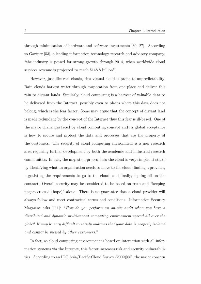
through minimisation of hardware and software investments [30, 27]. According
to Gartner [53], a leading information technology research and advisory company,
“the industry is poised for strong growth through 2014, when worldwide cloud
services revenue is projected to reach $148.8 billion”.
However, just like real clouds, this virtual cloud is prone to unpredictability.
Rain clouds harvest water through evaporation from one place and deliver this
rain to distant lands. Similarly, cloud computing is a harvest of valuable data to
be delivered from the Internet, possibly even to places where this data does not
belong, which is the fear factor. Some may argue that the concept of distant land
is made redundant by the concept of the Internet thus this fear is ill-based. One of
the major challenges faced by cloud computing concept and its global acceptance
is how to secure and protect the data and processes that are the property of
the customers. The security of cloud computing environment is a new research
area requiring further development by both the academic and industrial research
communities. In fact, the migration process into the cloud is very simple. It starts
by identifying what an organisation needs to move to the cloud; finding a provider,
negotiating the requirements to go to the cloud, and finally, signing off on the
contract. Overall security may be considered to be based on trust and “keeping
fingers crossed (hope)” alone. There is no guarantee that a cloud provider will
always follow and meet contractual terms and conditions. Information Security
Magazine asks [111]: “How do you perform an on-site audit when you have a
distributed and dynamic multi-tenant computing environment spread all over the
globe? It may be very difficult to satisfy auditors that your data is properly isolated
and cannot be viewed by other customers.”
In fact, as cloud computing environment is based on interaction with all infor-
mation systems via the Internet, this factor increases risk and security vulnerabili-
ties. According to an IDC Asia/Pacific Cloud Survey (2009)[68], the major concern

3
within the cloud environment is the issue of security. Although the majority of
the cloud providers claim that their systems are secure and robust, it has been
argued that all these strong security systems can be breached. The Cloud Security
Alliance’s initial report [31, 30] gives examples of such violations. These examples
include SQL-injection at the cloud platform level, phishing of the cloud provider,
and third party data control. There were some incidents regarding cloud down-
time, such as Gmail (October 2008, for one day), which increased concerns about
data not being available all the time. And crucially, moving sensitive data (e.g.
personal and medical) into the cloud raises critical questions regarding privacy and
confidentiality of such data as well as possible legal considerations regarding trans-
border data flow and the like. Like the unpredictable weather cloud, this cloud
could rain information anywhere. Like the weather forecasters, the cloud providers
can find that despite their best intentions and assurances about the safety of cloud,
they can be very wrong.
However, to counter these claims of insecurity, many of today’s cloud providers
claim in their service level agreements that they will protect the stored data and
that they guarantee the data availability almost 99.99 % of the time. However,
these are still only claims and in reality the cloud customers need to trust the
storage provider to protect their data while it is floating in the cloud. The reality is
that there have already been security breach incidents in cloud based services, such
as the corruption of Amazon S3, due to an internal failure caused simply because of
hashes applied by the customers resulting in a mismatch of files [1]. Another recent
incident that supports the argument that cloud providers cannot always fulfil their
security guarantee in the SLA, is when some of Amazon’s data centres located in
Northern Virginia (USA) went down on Monday 22nd October 2012 [102]. As
indicated on the Amazon website [102] the company’s cluster of cloud computing
services in Virginia were “currently experiencing degraded performance”. This

4 Chapter 1. Introduction
affected a number of popular Web sites and services, including Flipboard and
Foursquare. In fact, the same incident occurred about four months earlier due to
an electrical storm that caused some disturbance to the same data centres.
Furthermore, in some recent incidents, cloud customers have lost their data [16].
For instance, the crash in the Amazon’s Elastic Compute Cloud (EC2) service
permanently destroyed some of the customers’ data. When this incident took
place Amazon’s backup process seemed to be as simple as copying the data file
to another file on the same server or another server in the same data room. As a
result, Amazon failed in such a way that they could not restore the data. “And,
of course, this is the sort of reliability that Amazon has been selling with its cloud
services–including 99.9% up-time. Both promises seem to have been broken here”;
Blodget says [16]. Another example is when some users of Microsoft’s Hotmail
service reported that their entire Hotmail accounts had been completely deleted
without warning. They found that all messages in all folders (inbox, sent, deleted,
etc) had been wiped out [91]. The main reason behind this serious incident was a
result of storing all backups locally.
It would appear that cloud customers are enthusiastic about being allowed
to store their data in the cloud but at the same time they want the personal
satisfaction and comfort of checking for themselves (or through a trusted third
party) that their data is protected. To have the said comfort and satisfaction
in cloud security, we need to identify the critical security requirements that the
cloud customers want to assess. According to various studies [30, 35, 46, 71, 78,
104, 125, 132], the important security requirements that a cloud storage provider
should satisfy are confidentiality, integrity, availability, fairness (or mutual non-
repudiation), data freshness, geographic assurance and data replication.
Thus the customer satisfaction and comfort on security is proposed to be se-
cured by utilising cryptographic techniques including encryption, digital signatures

1.1. Motivation 5
and Proof-of-storage (POS) protocols. These protocols are a key component in
many secure cloud storage proposals in the literature. A POS is an interactive
cryptographic protocol that is executed between clients and storage providers in
order to prove to the clients that their data has not been modified or (partially)
deleted by the providers [71].
The main aim of this research is to assure the security of stored data in the
cloud. Simply we aim to encourage cloud users not to be exclusively reliant on the
cloud providers for the protection and security of their data. The motivation for
this research is provided in Section 1.1. Research objectives are listed in section 1.2
and the research questions are in section 1.3. Outcomes achieved by this research
are identified in section 1.4. Research significance is identified in section 1.5 and
the organisation of this thesis is described in section 1.6.
1.1 Motivation
Data security in cloud computing is a very important issue for various reasons.
One of them is that in the cloud environment there is a financial contract between
clients and the cloud provider. That is, the cloud clients should only pay for
the services they use. The cloud providers should guarantee that and should
compensate the customers for any loss that results from not fulfilling the service
level agreement. Organisations are the main targeted customers for the cloud and
they require a highly scalable access control for a large amount of stored data.
Many users (both individuals and organisations) prefer to choose a cloud provider
they trust and only inspect the SLA for standards compliance. They will most
likely choose not to bother themselves with the complexity of using POS schemes
with cloud storage services. Thus, it is up to the user whether to request using
these POS with cloud storage or not. POS schemes have been around for some

6 Chapter 1. Introduction
years and the question is: is there anybody who will use these POS? To the best
of my knowledge no one uses them in commercial cloud systems. However, adopt-
ing these ideas could be simpler in the future with all the advances in the ICT
industry.
This thesis focuses on introducing some solutions that allow the cloud cus-
tomers to obtain assurance regarding the confidentiality, integrity, availability,
fairness (or mutual non-repudiation), data freshness, geographic assurance and
replication of the data stored in the cloud. This research is motivated by the
following observations.
• Many of the proposed protocols require the cloud customers to trust the cloud
provider. Also, they see the security from the cloud provider perspective not
from the cloud customer side [15, 22, 132].
• Some of the service level agreements published by public cloud providers (e.g.
Amazon Simple Storage Service (S3) [8] and Google [61]) lack information on
how a cloud customer can control his or her data when stored in the cloud.
Also, in the event of not fulfilling the conditions, how the cloud provider will
compensate the cloud customers is not specified.
• Some recent incidents have violated the data availability and scalability
stated in the service level agreement (e.g. Amazon’s data centres went down
on Monday the 22nd of October 2012 [102]).
1.2 Research Objectives
As outlined in the previous section, the objectives that need to be addressed in
this thesis are:

1.3. Research Questions 7
1. To design a secure storage architecture for data storage in the cloud. This
architecture will focus on the security requirements including data confiden-
tiality, integrity, availability, fairness, freshness. (Chapter 3)
2. To allow the cloud customers to check where their stored data is located,
without relying on the word of the cloud provider. (Chapter 4 and 5)
3. To allow the cloud customers to verify that their stored data is replicated
over multiple and diverse locations; again without relying on the provider’s
claim. (Chapter 6)
1.3 Research Questions
The following are the main research questions or problems that are addressed in
this thesis:
1. “How can assurance be provided that the security requirements for data stor-
age in the cloud are met?”
In this thesis we elucidate the set of security properties that a secure cloud
storage application must fulfil. These includes confidentiality, integrity, avail-
ability, fairness (or non-repudiation), data freshness, geographic assurance
and data replication. Examination of the literature shows that there is no
single complete proposal that provides assurance for all of these security re-
quirements. In this thesis we design a secure storage architecture for data in
the cloud. By examining the existing proof-of-storage schemes, CloudProof
scheme by Popa et al. [104] and Dynamic Proofs of Retrievability (DPOR)
by Wang et al. [125] are identified as promising POS schemes that satisfy
the majority of the security requirements. We found that if we combined

8 Chapter 1. Introduction
these two schemes we could assure the security requirements including data
confidentiality, integrity, availability, fairness and freshness of the data.
2. “How can assurance be obtained of the geographic location of the data stored
in the cloud and SLA violations be detected?”
In this thesis we introduce an architecture for a new approach (GeoProof) for
geographic location assurance, which combines the proof-of-storage protocol
(POS) and the distance-bounding protocol. This allows the client to check
where their stored data is located, without relying on the word of the cloud
provider. This architecture aims to achieve secure and flexible geographic
assurance within the environment of cloud computing.
3. “How to enhance GeoProof to encompasses the dynamic POS schemes and
reduce the extra time resulting from computational overhead at the server?”
The proposed GeoProof may involve unnecessary delay when utilising typical
POS schemes, due to computational overhead at the server side. We enhance
the proposed GeoProof protocol by reducing the computational overhead at
the server side. We show how this can maintain the same level of security
while achieving more accurate geographic assurance.
4. “How can assurance of geographic replication for the stored data over multiple
and diverse locations be obtained?”
The cloud customers may want to be sure that their stored data is replicated
over separated physical locations. Such replication could protect against any
unavailability that could be caused by natural disasters or power shortages.
In this thesis we propose a proof of data file replication scheme. This scheme
allows the cloud customers to verify that their stored data is replicated over
multiple and diverse locations.

1.4. Research Outcomes 9
1.4 Research Outcomes
By addressing the research objectives and research questions, this thesis makes a
number of contributions and achievements.
1. The main challenges that face the acceptance of cloud computing have been
identified. In addition, the thesis identifies a set of security properties that
a secure cloud storage application must fulfil.
2. We elucidate the set of security properties that a secure cloud storage ap-
plication must fulfil. In addition, we design a secure storage architecture for
data in the cloud. This architecture will focus on the security requirements
including data confidentiality, integrity, availability, fairness and freshness.
This can be achieved by combining the promising POS schemes that sat-
isfy the majority of the security requirements. The research results were
published in:
• Albeshri, Aiiad Ahmad, Boyd, Colin, & Gonzalez Nieto, Juan M. (2012)
A security architecture for cloud storage combining proofs of retrievabil-
ity and fairness. In Proceedings of Cloud Computing 2012 : The Third
International Conference on Cloud Computing, GRIDS and Virtualiza-
tion, IARIA, Nice, France, pp. 30-35.
3. We introduce an architecture for a new approach for geographic location as-
surance, which combines the proof-of-storage protocol (POS) and the distance-
bounding protocol. This allows the client to check where their stored data is
located, without relying on the word of the cloud provider. This architecture
aims to achieve better security and more flexible geographic assurance within
the environment of cloud computing. The research results were published in:

10 Chapter 1. Introduction
• Albeshri, Aiiad Ahmad, Boyd, Colin, & Gonzalez Nieto, Juan M. (2012)
GeoProof : proofs of geographic location for cloud computing environ-
ment. In Proceedings of the 32nd International Conference on Dis-
tributed Computing Systems Workshops 2012, IEEE, Macau, China,
pp. 506-514.
4. We enhance the proposed GeoProof protocol by reducing the computation
overhead at the server side when utilising typical POS schemes that involve
a computational overhead at the server side. We show how this can maintain
the same level of security while achieving more accurate geographic assur-
ance. The research results were submitted to:
• Albeshri, Aiiad Ahmad, Boyd, Colin, & Gonzalez Nieto, Juan M. "En-
hanced GeoProof: Improved Geographic Assurance for Data in the
Cloud" submitted to International Journal of Information Security (Spe-
cial Issue: Security in Cloud Computing).
5. We propose a proof of data file replication scheme. This scheme allows the
cloud customers to verify that their stored data is replicated over multiple
and diverse locations.
1.5 Research Significance
This research advances knowledge in the area of cloud security by identifying and
understanding the characteristics and security requirements for the cloud environ-
ment and allowing the users of the cloud services to outsource their data without
the need to trust the cloud provider.
The proposed architectures in this thesis could be adopted by the cloud providers
in order to provide their customers with more control over their data while it is

1.6. Thesis Outline 11
stored in the cloud. In fact, cloud providers would need to adopt their systems
in order to implement the proof protocols that are always required in all con-
tributions. At the same time, as long as the cloud provider cooperates, these
mechanisms work with any type of cloud service (i.e. SaaS, PaaS and IaaS) in
which the cloud stores the user’s data.
1.6 Thesis Outline
The remaining chapters of this thesis are organised as follows:
Chapter 2: Cryptographic Background. This chapter provides an overview
of the cryptographic and coding primitives used in the thesis.
Chapter 3: Background. This chapter provides an overview of the concept
of cloud computing and identifies the main challenges that face the acceptance of
this new paradigm. Also, this chapter gives an overview of the different types of
security controls in this new environment. Moreover, this chapter identifies the
set of security properties that a secure cloud storage application must fulfil. These
include confidentiality, integrity, availability, fairness (or non-repudiation), data
freshness, geographic assurance and data replication. After that, it investigates
today’s commercial cloud storage vendors to see if they address the previous se-
curity requirements in their offers and services. Next, it provides an analysis of
existing secure cloud storage proposals from the literature, which may be used to
provide cloud customers with their security and assurance requirements.
Chapter 4: Combining Proofs of Retrievability and Fairness. This
chapter focuses on the design of a secure storage architecture for data in the
cloud. This architecture focuses on the security requirements including data confi-
dentiality, integrity, availability, fairness and freshness. This could be achieved by
combining the promising proof-of-storage (POS) schemes that satisfy the majority

12 Chapter 1. Introduction
of the security requirements.
Chapter 5: GeoProof: Proofs of Geographic Location for Cloud
Computing Environment. This chapter introduces a new approach for geo-
graphic location assurance, which combines POS and the distance-bounding pro-
tocol. This allows the client to check where their stored data is located, without
relying on the word of the cloud provider. This architecture aims to achieve better
security and more flexible geographic assurance within the environment of cloud
computing.
Chapter 6: Enhanced GeoProof: Improved Geographic Assurance
for Data in the Cloud. The aim of this chapter is to improve the proposed
GeoProof protocol by reducing the computation overhead at the server side. We
show how this can maintain the same level of security while achieving more accu-
rate geographic assurance.
Chapter 7: Proof of Geographic Separation. The aim of this chapter is
to discuss the argument of allowing the cloud customers to verify that their stored
data is replicated over multiple and diverse locations.
Chapter 8: Conclusion and Future Work. Conclusions and directions for
future research are presented in this chapter.

Chapter 2
Cryptographic Background
Data Security refers to the protection process for the stored data from unwanted
access or modifications by unauthorised users. Confidentiality, integrity and avail-
ability (CIA) are the main security properties. Confidentiality means to make
sure that only authorised clients with the appropriate rights and privileges can
access the stored data. Integrity means to protect the stored data from being
inappropriately modified (whether accidentally or deliberately). Availability refers
to assurance that the stored data is always available to be delivered to the users.
One way to ensure the data security (e.g. data confidentiality) is to use the cryp-
tographic and encoding techniques on the data before storing it.
This chapter provides an overview of the concept of data encryption and coding.
It identifies the main cryptographic and coding primitives. Also, this chapter gives
an overview of the hash function, Merkle Hash Tree and hash chain.
This chapter is organised as follows. Section 2.1 provides an overview of cryp-
tographic and coding primitives. Section 2.2 overviews the Merkle Hash Tree and
hash chain. Finally, this chapter is summarised in Section 2.3.
13

14 Chapter 2. Cryptographic Background
2.1 Cryptographic and Coding Primitives
Cryptographic and error control techniques can be used to protect data before it
is sent to the cloud. In this thesis these primitives will be used for the same reason
as will be seen in the next Chapters. In addition, digital signature, exponentiation
and pairing will be also used in the authentication process in order to verify the
authenticity of the retrieved messages.
The encryption tools could be used to provide some of the security services
for the data while stored and when being transmitted. Data confidentiality is an
example of such a security service; only authorised users can access the data. Data
integrity is another example; any modification to the data could be detected.
2.1.1 Encryption
Encryption involves using a cryptographic algorithm and a cryptographic key in
order to transform a plaintext into a ciphertext or not obvious text (Figure 2.1).
There are two types of cryptographic algorithms, symmetric and asymmetric en-
cryption [84].
Figure 2.1: Basic Encryption

2.1. Cryptographic and Coding Primitives 15
Symmetric Encryption: Symmetric or secret key ciphers involve the use of a
shared secret keys. This means that the encryption key is equal to the decryption
key. In general, there are two main types of the symmetric cipher: stream ciphers
and block ciphers.
Stream ciphers see the plaintext as streams of characters with size of 1 bit or
n-bit word. In this cipher, the plaintext is encrypted (and decrypted) one character
at a time. According to Menezes et al. [84], stream ciphers are used in real-time
applications such as pay TV and communications. This is because they are able
to run in high speed.
In block ciphers, the plaintext is encrypted (and decrypted) one block at a
time. The block size is commonly 64-bit or 128-bit [84].
Asymmetric Encryption: The asymmetric key ciphers are also known as pub-
lic key cipher, in which there are two keys used. This means that the encryption
key is not equal to the decryption key [84]. In this cipher, each player needs to
have two keys; a public key (which is made public) and a private key (which is
kept secret). The public key is used for the encryption process and the private key
is used for the decryption process.
2.1.2 Encoding
Encoding is very similar to the encryption process. However, the encoding process
is used to transform the plaintext into encoded text using an encoding algorithm.
Anyone who knows the decoding algorithm could decode the encoded data. That
is, there are no secret keys used in the encoding process while in encryption you
need to know two things, the decryption algorithm and the secret key.

16 Chapter 2. Cryptographic Background
2.1.3 Error-correcting Code
The error-correcting codes are coding techniques that are used to control the errors
in data. The main idea behind this technique is to transform the data into a larger
size by adding redundant symbols. Such redundancy will help the verifier to detect
the errors in the data and correct these errors. Also, the original data can be
recovered from a subset of encoded data. The error-correcting code is widely used
in the proposed POS schemes and the main principle behind that is to protect
against small changes in the file. For instance, if a malicious storage provider flips
one bit only, there is a non-negligible chance that the embedded authentication
tags will not be checked but the code will fail and detect an error.
Reed-Solomon [106] is well known example of the error-correcting codes.
These codes have great power and utility and are used commonly in many appli-
cations [117]. According to Wicker [128], “Reed-Solomon codes are optimal in that
their distance properties are the best possible, given their length and dimension”.
The parameters of the Reed-Solomon code are (n, k, n − k + 1 ); where n is the
block length of the code, k is the number of data symbols and n − k + 1 is the
minimum distance of the code. The minimum distance n − k + 1 (or equivalently
the measure of redundancy in the block n − k) is used to determine the ability of
a Reed–Solomon code of error-correcting. Juels et al. [69] gave an example of how
much storage overhead could result when applying the common (255, 223, 32)-
Reed-Solomon code. This code uses 32 redundant symbols to encode each block
of 223 data symbols, so there is a 14% overhead by adding error correction.

2.1. Cryptographic and Coding Primitives 17
2.1.4 Digital Signatures and Message Authentication Codes
Digital signature is a cryptographic tag added to a message so that its authenticity
can be verified mathematically. Digital signatures are based on the public key
cryptography in which the signer has two keys; a secret key only known to the
signer and a public key known to everyone [84]. The signer uses his/her secret key
to create the digital signature on the document. The receiver will use the signer’s
public key to verify the digital signature. The digital signature will provide the
document integrity security service. In addition, digital signatures can be used to
provide the non-repudiation security service. The digital signature usually makes
use of the hash function in order to reduce the message size before signing or
verifying. RSA (1024-bit long) is widely used digital signature schemes. Also,
the BLS (Boneh–Lynn–Shacham) [19] is another short digital signature (170 bits
long) that uses a pairing function for verification process. BLS signature is 170 bits
and is shorter than the RSA signature which is a 1024-bit long for a comparable
security level.
BLS Signature: Following Boneh et al. [17], let G be a large prime group with
generator g and a hash function H : 0, 1∗ → G.
• Key Generation:
1. SK = y ∈ Zp
2. PK = v ← gy
• Sign(M,SK)→ σ = H(M)y
• Verify(M,σ)→ e(σ, g) ?= e(H(v,M), v)
For the key generation, pick a random element y ∈ Zp. The secret key SK is y
and the public key PK is v ← gy. The signing phase takes a message M ∈ 0, 1∗

18 Chapter 2. Cryptographic Background
and the secret key y and outputs the signature σ which is the hash function on M
to the power of y. The verification process takes the message M and the signature
σ and outputs true if σ matches M or false otherwise.
BLS Aggregated Signature: In addition, the BLS signature provides an ag-
gregation property which allows the user to combine many signatures together into
a single aggregated signature σagg and still be able to verify them. Briefly, assume
there are n users whose signatures are aggregated; the key generation and signing
phases are the same as in BLS. In addition, we need to setup and sign individual
messages M1, ....Mk as follows [126].
• Key Generation:
1. SK = y ∈ Zp
2. PK = v ← gy
When setup is run multiple times we get: PK1 = gy1 , ....., PKn = gyn .
• Sign(M,SK)→ σ = H(M)y
When sign is run multiple times we get σ1 = H(M)y1 , ....., σn = H(M)yn
• Aggregate(σagg(M1, ....,Mn), σ,M)
– σ∗agg = σagg · σn+1 = H(M1)y1 ·H(M1)y1 · · · ·H(Mn)yn+1
• Verification:
– ∏e(gyi , H(Mi)) ?= e(σagg, g)

2.1. Cryptographic and Coding Primitives 19
The Message Authentication Code (MAC) MAC is a short information
(e.g. cryptographic hash function) that is used to help in providing the message
integrity and authentication ( i.e. proof of the identity of the source of the message)
[84]. Unlike digital signatures, MACs values are both generated and verified using
the same secret key. In principle, the verifier (who has the secret key) can verify
the authenticity of the retrieved data. Hash function-based (HMAC) is an example
of existing MACs [112]. HMAC uses a cryptographic hash function (e.g. MD5 or
SHA-1) in conjunction with a secret cryptographic key. The typical output length
of HMAC will be the same size as the underlying hash. For instance, the output
length of HMAC-MD5 is 128 bits and the HMAC-SHA1 is 160 bits. Also, we could
have a shorter MAC by truncating these MACs.
Digital signature and MAC provide same service of integrity authentication
where MAC is symmetric key and digital signature is a public key algorithm and
both are used for generation of the authentication tags in POS schemes. Since
digital signatures can be verified using only a public key, they are suitable for
publicly verifiable proofs. In POS schemes (e.g. [12, 11, 69, 115, 125]), the user
generates some authentication tags, which only the user (owner) can generate.
These could be secret key, signature, MAC or another element and then either
embedded in the data file or sent to the storage provider along with stored file.
Later on, the user challenges the storage provider with some indexes of certain
data blocks. The storage provider generates the proof, which is essentially a linear
combination of data block and these authentication tags.
2.1.5 Exponentiation
Exponentiation is an essential mathematical operation for public-key cryptogra-
phy. The square-and-multiply algorithm is a well-known technique in performing
20 Chapter 2. Cryptographic Background
exponentiation efficiently. However, this exponentiation algorithm still requires
significant time to undertake [84]. Simultaneous multiple exponentiation [84] is an
example of such algorithms that can do exponentiation much faster when several
exponentiations are required. The main idea behind this algorithm is to avoid
doing exponentiation separately and then doing multiplication afterward. Thus,
rather than doing each exponential separately, simultaneous multiple exponentia-
tion introduced a method to perform them simultaneously by sharing the squaring
part of the algorithm [84].
Some of the proof-of-storage schemes (POS) involve the exponentiation process
at the server side in order to compute the proof [14]. This may lead to a compu-
tational overhead at the server side. Although efficient exponentiation algorithms
are well known, computation time is still significant in comparison to basic oper-
ations such as hashing or symmetric key encryption. As we will see later in the
thesis, this time is critical in maintaining the geographic location of the stored
data. Moreover, using simultaneous multiple exponentiation is helpful to optimise
the computation involved in any proposed scheme.
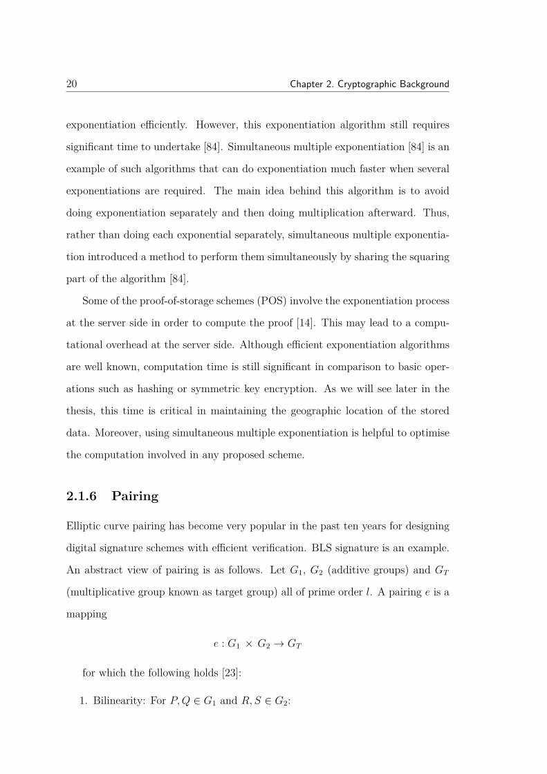
2.1.6 Pairing
Elliptic curve pairing has become very popular in the past ten years for designing
digital signature schemes with efficient verification. BLS signature is an example.
An abstract view of pairing is as follows. Let G1, G2 (additive groups) and GT
(multiplicative group known as target group) all of prime order l. A pairing e is a
mapping
e : G1 × G2 → GT
for which the following holds [23]:
1. Bilinearity: For P,Q ∈ G1 and R, S ∈ G2:

2.2. Merkle Hash Tree and Hash Chain 21
• e(P +Q,R) = e(P,R) · e(Q,R)
• e(P,R + S) = e(P,R) · e(P, S)
• Thus, e(aP, bR) = e(abP,R) = e(P,R)ab = e(bP, aR) = .....
2. Non-degeneracy: e(P,R) 6= 1
3. Computability: e(P,R) can be efficiently computed.
In addition to the importance of the bilinearity property, computational cost is
another critical issue in pairing. Some of the POS schemes use pairing in the
verification process to verify the retrieved proofs as we will see in Chapters 4, 5, 6
and 7.
In the last few years there has been considerable research into optimising the
implementation of pairings. Today, pairings can be computed in a time that
is competitive with exponentiation algorithms [131]. For instance, TinyPairing
(pairing-based cryptographic library for wireless sensors) is designed to implement
the bilinear pairing and pairing-related functions very efficiently and lightweight
[131].
2.2 Merkle Hash Tree and Hash Chain
A hash function H(x) is a mathematical algorithm that takes an input of an arbi-
trary length of data and outputs a fixed-length string. The main characteristics
of the hash function are [118]:
• Compression: it takes any length as an input and outputs a small and fixed
length string regardless of the length of the input.
• Efficiency: the computation effort of computing the hash output is relatively
small.

22 Chapter 2. Cryptographic Background
• One-Way: this function does not work in reverse. This means it is not
computationally feasible to find the value of x from H(x).
• Collision resistance: this means that it is computationally difficult to find
two different messages x and y such that H(x) = H(y).
1 2 i-1 i
1 2i-1 i
Figure 2.2: Merkle Hash Tree
SHA-1 and SHA-2 are common and widely used hash functions; also, SHA-3
[66] has been recently approved and probably will soon be replacing SHA-1 and
SHA-2 [95]. A hash tree (the concept is named after Ralph Merkle) is a type of
data structure constructed from a tree of hashes of data blocks. These hashes
could be used to authenticate the data blocks. A Merkle Hash Tree (MHT) is
constructed as a binary tree that consists of a root R and leaf nodes which are an
ordered set of hashes of the data blocks H(mi). It is possible to utilise the MHT to
authenticate both the values and the positions of data blocks. The leaf nodes are
treated in the left-to-right sequence thus, any data block (node) can be uniquely
identified by following this sequence up to the root (Figure 2.2). For instance, as
will be seen in Section 4.2, part of the generated proof by the cloud provider in

2.2. Merkle Hash Tree and Hash Chain 23
DPOR [125] is Ωi which is the set of node siblings on the path from the leaf i to
the root R in the MHT.
For example, to authenticatem2, you need the following siblings:H(m1), B and
R. Then you can check H(H(m2)||H(m1)||B)?
= R. Signing the root is equivalent
to signing each block. Changing blocks can be done efficiently; for example chang-
ing m1you need to recompute Ω = H(m1), A, R. This is really efficient because if
the tree is very big (e.g. 2d levels) you only need to recompute a limited number
of node siblings (about d hashes).
ii
i
i
i
i
Figure 2.3: Hash Chain
A hash chain is a sequential application of a hash function to a string x (Figure
2.3). For example, applying the hash function sequentially on the data block three

24 Chapter 2. Cryptographic Background
times, outputs a hash chain of length 3, H3(x) = H(H(H(x))). In general, a hash
chain of length n is built by applying a hash function H( ) sequentially to the value
x [65].
Hn(x) = H(H(...H(x)...)) (n times)
In the CloudProof [104] scheme, the hash chain value is used for freshness
(Figure 4.7). The hash chain is computed over the hash of the data in the current
attestation and the chain hash of the previous attestation. Thus, it is a sequence
of hashes, which contains current attestation and all history of attestations of a
specific block as follows: chain hash = H(data, previous hash chain value). There-
fore, if the sequence of attestations is broken, this means there is a violation of
freshness property. Despite the computational overhead of the chain hash, adding
a chain hash for data file causes a small overhead increase [104].
2.3 Summary
Security is an important issue when storing data. Confidentiality, integrity and
availability (CIA) are the main security properties. Cryptography helps in pro-
tecting some of these properties. This chapter overviews the needed cryptography
and encoding primitives that are used in the next Chapters, to assure data security
at various levels.

Chapter 3
Background
The main theme of this thesis, as described in Chapter 1, is to allow the users of
cloud services to outsource their data without needing to trust the cloud provider.
This chapter provides an overview of the concept of cloud computing and identifies
the main challenges that face the acceptance of this new paradigm. Also, this
chapter gives an overview of the different types of security controls in this new
environment. Moreover, this chapter will identify the critical security requirements
that a cloud storage provider should satisfy.
This chapter is organised as follows. Section 3.1 provides an overview of cloud
computing. Section 3.2 overviews cloud data storage in brief. Section 3.3 discusses
the security requirements for user data in the cloud storage. After that, Section 3.4
will investigate today’s commercial cloud storage providers and see if they address
the security requirements in their offerings and services. Section 3.5 overviews the
proof-of-storage (POS) protocols. Finally, the chapter is summarised in Section
3.6.
25

26 Chapter 3. Background
3.1 Cloud Computing
Cloud computing is an evolving term that describes the transformation of many
existing technologies and approaches to computing into something different. Cloud
computing splits application and information resources from the basic infrastruc-
ture, and the methods used to deliver them [36]. Cloud computing is essentially
a large-scale distributed and virtual machine computing infrastructure. This new
paradigm delivers a large pool of virtual and dynamically scalable resources, in-
cluding computational power, storage, hardware platforms and applications, which
are made available via Internet technologies. Gellman [54] identified cloud com-
puting as “it involves the sharing or storage by users of their own information on
remote servers owned or operated by others and accessed through the Internet or
other connections”. In fact, cloud storage could store any type of data that has
been stored locally on a PC. In the cloud, users could share the storage space,
memory, bandwidth, and processing power. As a result, users also share the cost
and pay as they go for what they use. In a simple form, cloud computing could
be seen as a utility service (e.g. electricity, water, ...etc).
3.1.1 Cloud Computing vs. Grid Computing
Grid computing is often confused with cloud computing. Grid computing is a
form of distributed computing that utilises a virtual supercomputer made up of a
cluster of networked machines working together to do very large tasks and sharing
resources [92]. In fact, many of the deployments in cloud computing are pow-
ered by grid computing implementations and constructions [109]. However, cloud
computing could be seen as the next step away from the grid utility model.

3.1. Cloud Computing 27
Internet
Calender
Finance
Communi
cation
Database
ComputationStorageNetwork
Memory
Figure 3.1: Cloud Computing
3.1.2 Advantages of Cloud Computing
Internet has led to a steady migration away from the conventional data centre
model to the cloud-based model. From the users’ perspective, the cloud acts as a
single point of access for all their computing needs anytime, anywhere in the world,
as long as an internet connection is available. In fact, cloud customers are able to
access any cloud-enabled systems regardless of their location or their devices [109].
Figure 3.2 shows some of the advantages of using the cloud environment. Some
of these benefits include:
• Cost reduction: One of the main reasons that attracts organisations to
move into cloud computing is to save money by reducing the investments
in new infrastructure. Indeed, cloud computing helps to minimise the costs
and complication of purchasing, configuring, and managing the hardware and
software needed to construct and deploy applications which are delivered via
the Internet [109].

28 Chapter 3. Background
Figure 3.2: Advantages of Cloud Computing
• Measured Service: Consumers use what they need on the Internet and
pay only for what they use.
• Dynamic allocation of resources (Elasticity): CPU, storage, and net-
work bandwidth could be allocated dynamically.
• Scalability: More efficient developments for underutilized systems. Also,
the scalability can vary dynamically based on user demands [109].
• High level of computing: Using cloud services provides users with a high
level of computing power. This is because many of today’s cloud providers
try to attract customers with high performance hardware and software.
• Reliable performance: That is controlled by the provider of the service
that is aiming to survive the competitive market. In addition, reliability is
often enhanced in cloud computing environments because service providers
use several redundant sites. This is attractive to enterprises for business
continuity and disaster recovery reasons.

3.1. Cloud Computing 29
Table 3.1: Cloud Service Models
Service Model Characterisation ExampleSoftware as a Service (SaaS) Deliver software
applications overInternet
Google Docs,Zoho, AmazonS3
Platform as a Service (PaaS) Provide developerswith deploymentplatform
Google AppEngine,MicrosoftAzure, AmazonEC2
Infrastructure as a Service(IaaS)
Provide a sharedcomputinginfrastructures suchas servers, networks,storage
Force.com cloudinfrastructure
3.1.3 Cloud Service Models
One widely accepted framework for cloud computing is the Software, Platform
and Infrastructure (SPI) model. This model comes from the three main services
provided by the cloud: infrastructure as a service (IaaS), platform as a service
(PaaS) and software as a service (SaaS). In fact, NIST, the Cloud Security Alliance
(CSA) and other organisations follow this framework along with many of today’s
cloud providers [78]. Cloud computing can provide any or all of IaaS, PaaS and
SaaS models. Table 3.1 shows the difference between these three models and gives
some examples for each one.
Cloud providers would need to adopt their systems in order to respond to
the proof protocols that are always required in all contributions enumerated in
this thesis. This may include the computational requirements for protocols and
accommodating the tamper proof verification device on their sites. At the same
time, as long as the cloud provider cooperates, these mechanisms will work with
any type of cloud service (i.e. SaaS, PaaS and IaaS) in which the cloud stores the
user’s data.

30 Chapter 3. Background
Figure 3.3: NIST Visual model of cloud computing [36]
Software-as-a-Service (SaaS): NIST [94] identifies software as a service (SaaS)
as follows: “The capability provided to the consumer is to use the provider’s appli-
cations running on a cloud infrastructure and accessible from various client devices
through a thin client interface such as a Web browser (e.g., web-based email). The
consumer does not manage or control the underlying cloud infrastructure, net-
work, servers, operating systems, storage, or even individual application capabili-
ties, with the possible exception of limited user-specific application configuration
settings”. In fact, in an SaaS model, a great amount of security responsibility is
taken on by the cloud provider.
The main advantage of using SaaS is to allow cloud customers a high level of
software functionality at a low cost. In fact, cloud customers will obtain the same
benefits of commercially licensed software without the associated complication of
deployment, support, patch management services or licensing [109]. Examples of
the cloud SaaS include Google Docs and Zoho.

3.1. Cloud Computing 31
Platform-as-a-Service (PaaS): NIST [94] identifies platform as a service (PaaS)
as follows: “The capability provided to the consumer is to deploy onto the cloud
infrastructure consumer-created applications using programming languages and
tools supported by the provider (e.g. java, python, .Net). The consumer does not
manage or control the underlying cloud infrastructure, network, servers, operating
systems or storage, but the consumer has control over the deployed applications
and possibly application hosting environment configurations”. The main purpose
of the PaaS model is to provide the developers with all needed components to
build and deliver web applications and services. In fact, developers do not need
to download or install software [109, 78]. This will help organisations to save a
significant part of their budgets. Indeed, the PaaS model provides a cloud-based
virtual development platform accessible via Internet. In addition, the PaaS con-
sumer has no control over the underlying cloud infrastructure (networks, servers,
operating systems, storage, ...etc). Also, the security responsibility somehow lies
in the middle, between the cloud provider and the cloud customer. Examples of
PaaS services include Google App Engine and Microsoft Azure.
Infrastructure-as-a-Service (IaaS): NIST [94] identifies infrastructure as a
service (IaaS) as follows: “The capability provided to the consumer is to provision
processing, storage, networks, and other fundamental computing resources where
the consumer is able to deploy and run arbitrary software, which can include
operating systems and applications. The consumer does not manage or control the
underlying cloud infrastructure but has control over operating systems, storage,
deployed applications, and possibly select networking components (e.g., firewalls,
load balancers)”. In the IaaS model, cloud consumers off-load hosting operations
and infrastructure management to the cloud provider. Cloud providers will provide
their customers with computer hardware, network (routers, firewalls, etc) and

32 Chapter 3. Background
other needed infrastructure, while the cloud customers will maintain ownership
and management of their applications [109]. This method helps organisations to
reduce the cost of purchasing data centres, servers, network equipment, software,
etc. In term of security, a minimum amount of responsibility is taken by the cloud
provider.
3.1.4 Cloud Deployment Models
The previous cloud services could be delivered to the users in different deployment
types. The popular deployment types include public, private, community and hy-
brid cloud. An organisation could implement one or more models or a combination
of the deployment models according to the organisation’s needs.
Internet
Figure 3.4: Public Cloud
Public Cloud: According to NIST [94], for the public cloud “the cloud infras-
tructure is made available to the general public or a large industry group and is
owned by an organization selling cloud services”. Figure 3.4 shows the public cloud
model. Thus, individual users or firms can make use of the public cloud. Examples
of public cloud providers include Amazon Web Services and Google App Engine.
In the public cloud, the infrastructures used to deploy the cloud are owned and

3.1. Cloud Computing 33
controlled by the cloud provider. This type of cloud computing is the model that
most cuts down the cost.
Private Cloud: The private cloud deployment model is preferred by organisa-
tions or users who do not want to share the cloud infrastructures with others. This
model provides the cloud users with more control over their data. However, private
cloud involves a high start-up cost. NIST [94] identifies private cloud as “the cloud
infrastructure that is operated solely for an organization. It may be managed by
the organization or a third party and may exist on premise or off premise”. The
private cloud could be classified into two types: ’off-premises’ and ’on-premises’.
Figure 3.5 shows the two types of private cloud. ’Off-premises’ means that the
cloud infrastructures are hosted remotely in the cloud but not shared with oth-
ers and dedicated only to one customer. ’On-premises’ on the other hand, means
that the cloud infrastructures are located locally in the physical location of the
organisation.
Community Cloud: The community cloud model usually works for organisa-
tions within the same community with common concerns (security, compliance,
etc). In this model, the participant organisations share the cloud infrastructures,
which may reside off-premises or on-premises in one of these organisations (Figure
3.6). NIST [94] describes the community cloud as “the cloud infrastructure that is
shared by several organizations and supports a specific community that has shared
concerns (e.g. mission, security requirements, policy, and compliance considera-
tions). It may be managed by the organizations or a third party and may exist on
premise or off premise”.
Hybrid Cloud: The hybrid cloud deployment model is a combination of two or
more of the previous models (i.e. public, private and community cloud) (Figure

34 Chapter 3. Background
Cloud
Infrastructure
Governemnt
Internet
Cloud
Infrastructure
GovernemntIntranet
Organisation’s
Boundry
Off-premises Private Cloud On-premises Private Cloud
Figure 3.5: Private Cloud
Cloud
Infrastructure
Governemnt
Organisation’s
Boundry
Internet
Finance
Bank
Insurance
Company Internet
Figure 3.6: Community Cloud

3.1. Cloud Computing 35
Cloud
Infrastructure Cloud
Infrastructure
Governemnt
Organisation’s
Boundry
Public Cloud
Private Cloud
In tern e
t
Comm
Finance
Figure 3.7: Hybrid Cloud
3.7). NIST [94] identifies the hybrid cloud as “the cloud infrastructure is a com-
position of two or more clouds (private, community, or public) that remain unique
entities but are bound together by standardized or proprietary technology that
enables data and application portability (e.g., cloud bursting)”.
The techniques described in the remainder of this thesis are important when
data is stored outside an organisation’s control. This always applies to the pub-
lic cloud model and may also apply to all other models if they include a public
component.
3.1.5 Cloud Computing Concerns
Cloud computing is new in the field of the ICT. Figure 3.8 shows the top concerns
and challenges that organisations have with regard to cloud computing. The scale
used is 1 to 5, with 1 being not at all important and 5 being extremely important
[68]. These concerns are regarding the cloud performance, regulatory requirements,
data availability, cloud integration, security and others.

36 Chapter 3. Background
Figure 3.8: The top concerns and challenges within cloud environment [68]
According to the literature [30, 35, 46, 51, 52, 54, 68, 71, 75, 78, 83, 94, 109, 111],
security is the major concern for the individuals and organisations when moving
into the cloud. One of the major challenges that face cloud computing is how to
secure the data when stored in the cloud. Each time an individual, an organisation
or a government adopts the cloud to store data, privacy or confidentiality questions
may arise [54]. The main idea is whether to trust the cloud provider or not. As
we will see in this thesis, many of today’s cloud providers claim that they provide
a high level of security and protection to their clients’ data. However, all these are
just claims written in the service level agreement (SLA) but with no enforcement.
In other words, the users need to trust the cloud provider in order to get the benefit
of utilising cloud technologies.
Organisations want to be sure that the SLA with the cloud providers covers the
important legal issues that are critical to the organisation’s operations [78]. For
instance, the SLA should address the privacy of the customer’s data being stored
in the cloud. Cloud providers must provide: a guarantee that they protect the
data of their customers, how to handle these data, how to move the data in case of
changing the cloud provider, who owns the data and how to delete the data upon

3.2. Data Storage in The Cloud 37
the end of the contract.
Decision makers may pause to take advantage of moving into the cloud envi-
ronment because they want to assure the protection of their data in the remote
storage. They want to be sure about who controls the data in the cloud, the
user or the cloud provider. Also, does the cloud provider comply with required
law and regulations in regard to the data? Another issue is where these data will
reside? Is this location appropriate in terms of the law and regulations? Is there
any method to prevent the cloud provider to change the location of the storage
facilities into another cheaper one? Do we need to rely on the trust we gave to the
cloud provider to protect our data? Moreover, what about the data replication in
the cloud? This is important in case of natural disasters.
Appendix-A identifies the major security controls for cloud computing in gen-
eral. It provides a broad overview on the important security requirements for the
cloud environment. In the contributions of this thesis we focus on data storage.
3.2 Data Storage in The Cloud
Cloud computing offers a variety of services and computational needs for indi-
viduals and organisations. Data storage in the cloud is one of these important
services. However, there are some issues that need to be considered when utilising
the remote storage in the cloud. In fact, cloud customers do care about the con-
fidentiality, integrity and availability. It is true that the cloud customers have the
option to trade the privacy of their data for the convenience of software services
(e.g. web based email and calendars). However, this is generally not applicable in
the case of government organisations and commercial enterprises [30, 46, 71, 78].
Such organisations will not consider cloud computing as a viable solution for their
ICT needs, unless they can be assured that their data will be protected at least to

38 Chapter 3. Background
the same degree that in-house computing offers currently.
Many of today’s cloud providers claim in their service level agreement that
they will protect the stored data and they guarantee the data availability almost
99.99%. However, these are still only claims and in reality the cloud customers need
to trust the storage provider to protect their data while being stored in the cloud.
Yet, none of today’s storage service providers in the cloud (e.g. Amazon Simple
Storage Service (S3) [8] and Google’s BigTable [61]) guarantee any security in their
service level agreements (SLA). Moreover, there have already been security breach
incidents in cloud-based services, such as the corruption of Amazon S3, due to an
internal failure caused by mismatching files with customers’ hashes [1]. In addition,
there are some very recent incidents that support the argument that the cloud
provider does not always fulfil what they promise in the SLA. For instance, some
of Amazon’s data centres went down on Monday the 22nd of October 2012 [102].
This affected a number of popular Web sites and services, including Flipboard
and Foursquare. A similar incident happened about four months earlier due to
an electrical storm that caused some disturbance to the same data centres. These
data centres are located in Northern Virginia (USA) and the company’s cluster
of cloud computing services in Virginia were “currently experiencing degraded
performance” as indicated on the Amazon website [102].
Thus, cloud customers are enthusiastic to be allowed to store their data in the
cloud and at the same time they would like to be able to check by themselves (or a
trusted third party) that their data is protected. To deal with this issue, we need to
identify the critical security requirements that the cloud customers want to check.
According to the literature [30, 35, 46, 71, 78, 104, 125, 132], the important secu-
rity requirements that a cloud storage provider should satisfy are confidentiality,
integrity, availability, fairness (or mutual non-repudiation), data freshness, geo-
graphic assurance and data replication. We explore these requirements in Section

3.3. Security Requirements for Data Storage in Cloud 39
3.3.2 after considering the options for data storage.
Proof-of-storage (POS) protocols have been introduced as a means of enabling
cloud service customers to verify the correct behaviour of cloud service providers.
A POS scheme is an interactive cryptographic protocol that is executed between
clients and storage providers in order to prove to the clients that their data has not
been modified or (partially) deleted by the providers [71]. The POS protocol will
be executed every time a client wants to verify the integrity of the stored data.
A key property of POS protocols is that the size of the information exchanged
between client and server is very small and may even be independent of the size
of stored data [30]. Examination of the literature shows that there is no single
complete proposal that provides assurance for all of these security requirements
(Section 3.5). Also, some existing secure cloud storage schemes are designed only
for static/archival data and are not suitable for dynamic data.
3.3 Security Requirements for Data Storage in
Cloud
This section discusses the overall security requirements for cloud storage as iden-
tified from the literature. There are several security properties that need to be
assured when storing the data in the cloud, as discussed in many related publica-
tions (e.g. [78, 127]). These requirements include: data confidentiality, integrity,
availability, public verifiability, fairness, data freshness, geographic assurance and
data replication. Confidentiality, integrity and availability (CIA) are widely agreed
to be important properties that many users are concerned about with their data,
whether stored in the cloud or elsewhere. The other listed properties are all about
the question of not having to trust the cloud provider. Some recent incidents may

40 Chapter 3. Background
support the importance of these requirements.
User’s
Data
Cloud Stored?
(Not Processed)
What
Data?
Where
Data?6- Data Location
7- Data Replication
Dynamic?4- Data Freshness
5- Data Fairness
1- Data Confidentiality
2- Data Integrity
3- Data Availability
Figure 3.9: Security Requirements for Data Storage
In general, by focusing on the user’s data, we could classify the data in the
cloud into two types; data that is processed by the cloud provider and data that
is simply stored (as shown in Figure 3.9 ).
3.3.1 Processed Data
Processed data means that the data involves computation and processing by the
cloud provider while stored in the cloud. Customers need to maintain the con-
fidentiality of their data in communication and storage processes within cloud
computing environment. One way to ensure the confidentiality of data while using
the cloud is to encrypt all data before sending it to the cloud. The problem is that
encryption limits data use. In addition to storing and retrieving the data, informa-
tion systems need to perform more complicated operations, which will be nearly
impossible in the case of encrypted data [110]. Moreover, searching and indexing
the encrypted data is difficult and not efficient [30]. Recently, cryptographers in-
troduced some techniques to solve problems associated with processing encrypted
data, which make it possible to do operations on encrypted data. Such operations

3.3. Security Requirements for Data Storage in Cloud 41
may be performed by the cloud provider as a service to the user, without requir-
ing the user to decrypt the data. Searchable and homomorphic encryption are
examples of these techniques.
Homomorphic Encryption: Homomorphic encryption was first introduced by
Rivest et al. in 1978 [110]. It involves performing computations on encrypted data
without revealing or decrypting it. Homomorphic cryptosystems can be classified
into two types, partially homomorphic and fully homomorphic. A partially ho-
momorphic cryptosystem uses only addition or multiplication for computation on
plaintext. Unpadded RSA is an example of partially homomorphic cryptosystems
[55, 56]. Generally, the main advantage of a partially homomorphic cryptosystem
is that it is more efficient than the fully homomorphic cryptosystem [6].
On the other hand, a fully homomorphic cryptosystem allows both operations
(addition and multiplication) for the computation on plaintext. These cryptosys-
tems are perfect for untrusted environments such as cloud computing, where all
private computations are outsourced. In 2009, Craig Gentry (IBM) [55, 56] intro-
duced the first fully homomorphic encryption scheme with the use of lattice-based
cryptography which involved a dramatic increase of ciphertext size and compu-
tation time. However, the work in this area is still continuing and possibly may
become more efficient for many applications. Examples of such work include [57],
[24], [59] and [58].
Searchable Encryption: Although traditional encryption will preserve the con-
fidentiality and integrity of data stored in the cloud, it has some limitations, such
as the searching process over the stored encrypted data. When customers need to
search their stored data there are two basic solutions; the first one is to download
the whole data and then decrypt it in the customer side, but this solution involves a

42 Chapter 3. Background
high communication complexity. The second solution is to store searching indexes
on the customer side, but these indexes could grow too large [71].
Searchable encryption provides a solution that will maintain the searching in-
dexes. Search index will be hidden (encrypted) except for authorised users who
have the appropriate token. According to Chow et al. [30], cloud customers may
use searchable encryption to encode the search query and send it to the cloud
provider. The cloud provider will use this encrypted search query and return the
document that matches the search query without learning any information.
There are various types of searchable encryption methods, such as Symmetric
Searchable Encryption (SSE) and Asymmetric Searchable Encryption (ASE). Each
one of these methods is suitable for particular application scenarios. For instance,
Symmetric Searchable Encryption (SSE) is useful in such cases where the customer
or user who requests (searches) the data is also the one who creates it initially.
The customer needs to send a token that contains a keyword w and the provider
will return the document (encrypted) that contains w. Furthermore, the cloud
provider will know nothing about the data unless he/she knows the token [71].
The second type is Asymmetric Searchable Encryption (ASE). ASE is useful in
such cases where the customer or user who requests (searches) the data is different
than the one who generates it initially. Customers need to send a token that
contains a keyword w and the provider will return the document (encrypted) that
contains w without any leakage at the data. According to Kamara and Lauter
[71], ASE will provide better functionality, but weaker security and inefficiency.
Byun et al. [28] said that ASE method is subject to a dictionary attack for the
token. As a result of that, the cloud provider can guess the customer’s keyword
and then the file that contains that keyword.

3.3. Security Requirements for Data Storage in Cloud 43
3.3.2 Stored Data
Stored (not processed) data means there is no need to process the data while stored
in the cloud. If the data is only stored and will not be processed, then the data
owner will be worried about data integrity and availability. Data confidentiality is
less of a problem than for processed data, as the user can encrypt the data in any
way chosen before sending it to the cloud storage, whereas for processed data a
specific encryption scheme is needed. Nevertheless, security properties for stored
data are complementary to those for processed data. All of our contributions can
be applied even if data is encrypted to allow processing by the cloud provider. In
this thesis we focus on the security of stored data independent of processing. The
previous requirements (CIA) are sufficient if the data is only static (archive) but
what about if the data is dynamic? This adds freshness and fairness to the list
of security requirements, because the data is changing and we need to deal with
issues such as who changed it, and also make sure that the retrieved data is always
the latest update. Moreover, the argument of where to store the data elevates the
data geographic location requirement and the data replication and separation.
Data Confidentiality: refers to “the prevention of intentional or unintentional
unauthorized disclosure of information” [78]. Data confidentiality ensures that
only authorised clients with the appropriate rights and privileges can access the
stored information. The need for confidentiality of the data being stored in the
cloud is one of the biggest obstacles to the adoption of cloud storage. Cloud
customers may need to be sure that the cloud storage provider does not learn any
information about their data while it is stored in the cloud. The confidentiality of
the client data can be protected using encryption, although the cloud provider may
still be able to predict some information based on monitoring the access patterns of
clients [104]. Many existing secure storage proposals provide data confidentiality

44 Chapter 3. Background
by allowing clients to encrypt their data before sending it to the cloud. However,
critical issues such as key management may be problematic, especially when we
have a multiple user scenario.
Data Integrity: ensures that the stored data has not been inappropriately mod-
ified (whether accidentally or deliberately). Data integrity becomes more challeng-
ing when adopting cloud computing where cloud customers outsource their data
and have no (or very limited) control over their stored data from being modified
by the storage service provider. Thus, cloud customers are aiming to detect any
unauthorized modification of their data by the cloud storage provider.
Data Availability: ensures that users are able to obtain their data from the
cloud provider when they need it. Cloud customers want to be sure that their
data is always available at the cloud storage. To this end, a number of proof-
of-storage protocols have been devised that allow the cloud provider to prove to
clients that their entire data is being stored, which implies that the data has not
been deleted or modified. Section 3.5 discusses some of these schemes.
Public Verifiability: means that service providers allow authorised third par-
ties (such as a third party auditor (TPA)) to perform periodical availability verifi-
cations on behalf of their customers. In cloud computing environments, customers
may need to allow a TPA to verify the integrity of the dynamic data stored in the
cloud storage [125]. Public verifiability allows the cloud customers or their TPA to
challenge the cloud server for correctness of stored data. In fact, security require-
ments can be inter-related. For instance, when a TPA is delegated to perform
verification, the confidentiality could be compromised. However, this issue can
be resolved by utilising a verification protocol that allows TPA to verify without
knowing the stored data [125].

3.3. Security Requirements for Data Storage in Cloud 45
Freshness: ensures that the retrieved data is fresh, i.e. it contains the last up-
dates to the data. This is very important in shared and dynamic environments
where multiple users may simultaneously update data. Cloud users need to en-
sure that the retrieved data is the latest version. To the best of our knowledge,
CloudProof [104] is the only cloud storage scheme that addresses freshness.
Fairness: or mutual non-repudiation, ensures that a dishonest party cannot ac-
cuse an honest party of manipulating its data [132]. If a dispute arises between
a client and storage provider regarding whether the correct data is stored then it
may be necessary to invoke a judge to decide who is right. Fairness can be im-
plemented by using digital signatures. Clients may want to have a signature from
the provider acknowledging what data is stored. Providers may want signatures
from clients whenever the stored data is altered, with deletion being an important
special case. In the case of cloud computing, fairness assurance becomes more
challenging especially when dealing with dynamic data.
Geographic Assurance: involves ensuring that the customer data has not been
stored in a location contravening location requirements specified in the SLA. A
critical obstacle that may face any organisation thinking to migrate to the cloud
computing, is where will their data physically reside? This is because there may
be certain legislative requirements on data and operations to remain in certain
geographic locations. In addition, the location of the data storage has a significant
effect on its confidentiality and privacy. This is due to the different laws and regu-
lations that vary between countries around the globe. Note that certain regulations
and laws require data and operations to reside in specific geographic locations [30].
For instance, according to Australia’s National Privacy Principles [4], it is illegal
to locate any personal information about individuals across the country borders

46 Chapter 3. Background
unless they have similar regulations. Many of the cloud providers claim that they
will locate the data in a specific region and will not change it. However, there is
no guarantee that the cloud provider may not change the location intentionally
(seeking cheaper infrastructures) or accidentally. In fact, many of today’s cloud
providers claim in the service level agreement (SLA) that the data will be stored
and maintained in certain geographic locations. However, cloud customers need
to trust the cloud provider and the only guarantee that the cloud provider will
meet its commitment is through the contract itself. Also, cloud service providers
may violate the SLA by intentionally or accidentally relocating the stored data
into remote data centres seeking cheaper IT costs, that may be located outside
the specified geographic boundaries. For this reason, cloud customers may need
to verify that their data are located in the same geographic location specified at
contract time and make sure that the cloud service provider continues to meet
their geographic location obligations.
Customers can get the benefit of applying cryptography and make use of some
existing protocols that may help them to monitor the geographic location of their
data and make sure that cloud providers did not change it. Distance bound-
ing protocol [67] is an example of a cryptographic protocol that may be used to
monitor the geographic location of the remotely stored data. In addition, there
are other mechanisms that been designed to provide a geographic assurance. For
instance, Padmanabhan and Subramanian [98] introduced and evaluated three
distinct techniques, GeoTrack, GeoPing, and GeoCluster, for determining the ge-
ographic location of Internet hosts. GeoTrack is based on the DNS names of the
host where they can predict the geographic location from the DNS names. GeoP-
ing is used to find the geographic location of the host by calculating the network
delays between server and hosts. Also, GeoCluster could be used to determine the
geographic location of the hosts by using the BGP routing information. Although

3.4. Commercial Cloud Storage Providers 47
these techniques are mainly used by servers to detect the geographic location of
hosts, they may be used the other way round within the new paradigm of cloud
computing, where customers will check and monitor the location of servers and
data.
Chapters 5 and 6 provide more details of the existing techniques that could be
used to provide assurance of the geographic location of the data in the cloud.
Data Replication: ensures that the stored data has been replicated (e.g. back-
ups) in separate physical locations. Another issue that arises when moving into
the cloud, is whether the cloud customer wants to store important files in a single
storage location or replicate them in multiple storage locations. It is important
to use storage that is geographically distributed. In fact, storing multiple copies
in different locations (and not very close) is a good technique to protect against
any unavailability that could be caused by natural disasters or power shortages.
Although many of today’s cloud providers claim that they replicate the stored
data in diverse locations, there is no technique that allows the cloud customers to
verify that their data have been replicated.
Chapter 7 will provide more details in regards to the issue of the data replication
in the cloud.
3.4 Commercial Cloud Storage Providers
Today there are many cloud computing providers who provide remote storage ser-
vices. For example, Google, Amazon and Salesforce.com are well known examples
of such providers. We made a simple investigation to find out exactly what stor-
age providers offer in regards to the previous security requirements for the data
storage.

48 Chapter 3. Background
3.4.1 Examples of Storage Providers
Table 3.2 shows examples of services provided by Amazon, Google and Sales-
force.com, which are the prominent commercial players in the cloud environment.
Table 3.2: Commercial Cloud Storage Providers
Storage Provider Storage ServiceAmazon Simple Storage Service (S3).
web services interface used for datastore/retrieve
Google Google Cloud Storage. An onlinestorage web service by Google.Google Drive. File storage andsynchronization service by Google
Salesforce.com Salesforce.com data Storage. Data storage andfile storage are calculated asynchronously
3.4.2 Analysis of Security Requirements
Table 3.3 provides a summary of the degree to which the security requirements
identified in Section 3.3 are met by the cloud services provided by these three
organisations. We gathered information from SLAs, terms and conditions docu-
ments, provider websites, provider frequently asked questions (FAQ) lists, provider
privacy statements, provider ’getting started’ guides and provider security guides.
Regarding data confidentiality, all three providers claim that they provide and
support encryption. Many cloud providers allow their customers to encrypt data
before sending it to the cloud. For instance, Amazon S3 makes it optional to users
to encrypt data for additional security, but not recommended in the case of third
party or external auditors [8]. Cloudfront is an Amazon web service which pro-
vides data confidentiality while being transferred. Google [64] and Salesforce.com
[113] support protection of sensitive data while it is being transmitted, with the
use of SSL. However, important questions have not been answered yet. For in-

3.4. Commercial Cloud Storage Providers 49
stance, who gets/grants cryptographic keys? Is the cloud provider the only party
to encrypt/decrypt the stored data?
Integrity claims have also been identified in many of the service agreements with
the cloud providers. For instance, Amazon S3 indicates that they will regularly
verify the integrity of customer’s data and detect any data corruption by using
a combination of Content-MD5 checksums and cyclic redundancy checks (CRCs)
[8]. If any data corruption is detected, it will be repaired by using other copies in
the redundant storage. Google claims that they protect the data integrity, with
no further details. Salesforce.com also claims that they assure the data integrity
but with no details [113]. However, the question of whether the user can obtain
checksums has not been answered yet.
The majority of cloud storage providers claim that they assure that the stored
data will be available all the time with 99.99%. For instance, Amazon S3 claims
in its website [8] that the S3 is designed to provide a 99.999999999% availability
of data over a given year. This availability level corresponds to an average an-
nual expected loss of 0.000000001% of data. Amazon S3 claims that they achieve
this high percentage by copying customers’ data redundantly on multiple storages
across multiple devices located in diverse locations. This could help in the case
of natural disasters. However, one recent incident [102] indicates that this is not
the reality. Also, Google claims in its SLA that it will assure the data availability
by at least 99.9% of the time in any calendar month. Also, Google replicates the
customer’s data at two levels [63]. Firstly, it replicates the data in multiple data
centres that are geographically distributed. Secondly, this data is also replicated
within each data centre. Salesforce.com indicates that they equip “world-class fa-
cilities” with proven high availability infrastructure support and use the idea of
the complete redundancy [114] for high data availability.
Regarding public verifiability, Amazon indicates that it performs its own au-

50 Chapter 3. Background
diting and has successfully completed a Statement on Auditing Standards No.
70 (SAS70) Type II Audit [7]. Google states that they may only share informa-
tion with third parties in conformity with their Privacy Policy and the SLA [64].
Google claims that it has successfully completed a Statement on Auditing Stan-
dards No. 70 (SAS70) Type II Audit, HIPAA and PCI DSS regulations [62, 64].
Salesforce.com also states that it complies with ISO 27001, SAS 70 Type II and
SysTrust regulations. All the three providers offer capabilities for their customers
that help them to meet the compliance requirements with different regulations and
generate compliance reports and share them with their customers. Moreover, all
the listed providers allow independent auditing in accordance with SAS 70 Type
II.
Despite an extensive search, we could not find any related information in the
published documents that discusses the data freshness or fairness.
In regard to the geographic restrictions, Amazon, Google and Salesforce.com
promise that all data will reside in one region (that which is specified at contract
time), but there is no guarantee that cloud providers will always fulfil user’s re-
quirements. Similarly, they give the option to replicate the data (of course with
extra charges) but there is no guarantee and the cloud customers need to trust
that the cloud providers will always fulfil the conditions of the contract.

3.4. Commercial Cloud Storage Providers 51
Table 3.3: Security Requirements Provided for Cloud Storage
SecurityService
Amazon Google Salesforce.com
Confidentiality Yes.- Encrypt dataat storage- Cloudfront
Yes.- Encrypt dataat storage- SSL
Yes.- Encrypt dataat storage- SSL
Integrity Usescombination ofContent-MD5checksums andcyclicredundancychecks (CRCs)to detect datacorruption
Yes.No details
Yes.No details
Availability Guarantee99.999999999%dataavailability.Replication
Dataavailability byat least 99.9%.
Equip aworld-classfacilities.Redundancy
Freshness N/A N/A N/AFairness N/A N/A N/APublicVerifiability
Securitycontrols areevaluatedbi-annual byan independentauditor inaccordancewith SAS70Type II
Independentauditor inaccordancewith SAS 70Type II
Independentauditor inaccordancewith SAS 70Type II
GeographicAssurance
Yes.Allow tochoose whereto store thedata
Yes.Allow tochoose whichdata centre
Yes.No details
DataReplication
Yes.Allow tochoose whereto replicate thedata
Yes.two levelReplication.
Yes.No details
N/A = Nothing found in the published documents

52 Chapter 3. Background
In general, many cloud storage providers claim that they will offer the needed
security requirements for the stored data. However, is it possible to allow the cloud
customer to not trust the cloud providers and keep some control over their data
while it is stored in the cloud?
3.5 Proof-of-Storage (POS) Schemes
Outsourcing storage and computing resources raises some serious security issues
including a potential need for integrity verification for the outsourced data. Cloud
customers might need to make sure that their data has not been modified by
providers. The integrity of customers’ data in the cloud needs to be assured.
Proof-of-storage (PoS) is a cryptographic technique that may be used to verify the
integrity of remotely stored data. A POS scheme is an interactive cryptographic
protocol that is executed between client and server in order to prove to the clients
that its data has not been altered or modified by the server. The main advantage
of a POS scheme is that it allows the client to verify the data without the need for
the client to retain a copy. The POS protocol is executed every time a customer
wants to verify the integrity of its data. Proof-of-storage protocols could be used
privately where only the client who encrypted the data can execute the protocol to
verify the data. On the other hand, such protocols could be used publicly where
everyone knows the client’s public key and can execute the protocol and verify
the integrity of data. The useful feature about PoS protocol is that the size of
information exchanged between client and server is very small and independent of
the size of stored data.
In general, all the proposed POS schemes share some generic characteristics as
follows:
Setup phase: in all POS schemes the data file is prepared before it is sent to

3.5. Proof-of-Storage (POS) Schemes 53
Figure 3.10: Generic Overview of proof-of-storage Scheme (POS)
the remote storage. First, the file is divided into small blocks then an error-
correcting code (e.g. a Reed-Solomon code) is applied in order to meet the
data availability requirement. The resulting file is then encrypted (e.g. using
a symmetric-key cipher). The next step is to associate each data block (or chunk
of blocks) with a cryptographic tag such as an MAC or a digital signature. Some
POS schemes (like Proof of Retrievability (POR) [69] ) embed these cryptographic
tags inside the encoded file and then hide the location of these tags by applying
a pseudorandom permutation (PRP) on the file. In many cases, the generated
tags are sent along with the encoded file to the cloud storage. In addition, this
phase involves the Key Generation process, a randomized algorithm that is used
to generate cryptographic key material.
Variants: the size of the data block is an important variant in many POS
schemes. This is because of the associated communication and computational
costs. For example, Jules and Kaliski [69] suggest that a block size of l = 128 bits is
a natural choice as it is the size of an AES block. Of course, if a different encryption
algorithm is used with a different block size, then it will be appropriate to choose
different variable l. Another important variable is what type of cryptographic tag
is used and how are they computed? In general, we could classify these variants

54 Chapter 3. Background
into two types: traditional and perturbed tags. The traditional tags could be
simply an MAC or digital signature computed over the data blocks. In this case,
the verifier needs to keep these tags and release the secret key to the prover and ask
the prover to generate the required tags on specific blocks. Upon receiving these
tags, the verifier is able to verify them and assured the integrity of the stored data.
On the other hand, the computation process of the perturbed tags involves some
secret element that is only known to the verifier (e.g. [115] and [125]).
Challenge-Response phase: the verifier generates the challenge message,
which is normally random indexes of data blocks; some POS schemes associate
these indexes with random values to be used in computing the proof. The verifier
then sends the challenge message to the cloud provider. The Proof Generation
process is run by the storage provider in order to generate the proof transcript
which could be a set of corresponding tags or, in many cases, an aggregation
of the perturbed tags and aggregation of data blocks. The proof transcript is
simply the set of messages exchanged between the verifier and the prover. A proof
transcript allows the verifier to derive the proof in order to check the integrity
of the challenged blocks. Upon receiving the response from the storage provider,
the verifier executes the Proof Verification protocol to verify the validity of the
retrieved proof.
Proof-of-storage schemes (POS) can be categorised into two types, static and
dynamic. In the static schemes, clients store their data and never change or
update it. In the dynamic schemes, clients can update the stored data. In the
following two subsections, we review existing proposals for POS protocols. Table
3.4 lists the schemes reviewed and indicates the security requirements that are
satisfied by them. The entry with the dagger (†) indicates that the property is only
partially satisfied. It can be seen that no single proposal encompasses all security
requirements identified in Section 3.3. The security requirements in the table

3.5. Proof-of-Storage (POS) Schemes 55
are Confidentiality (C), Integrity (I), Availability (A), Public Verifiability (PV),
Freshness (Fr) and Fairness (Fa). In regard to geographic assurance and proof of
replication, none of the POS schemes address these two requirements. However,
we show how we can provide assurance of geographic location and data replication
by combining a distance bounding protocol with a POS scheme (Chapters 5, 6 and
7).
Table 3.4: Overview of the proof-of-storage (POS) schemes.
POS Scheme C I A PV Fr Fa TypeProof ofRetrievability (POR)[69]
! ! ! ! % % Static
Provable DataPossession (PDP)[11]
! ! ! ! % % Static
Compact POR [115] ! ! ! ! % % StaticTahoe [129] ! ! % % % % StaticHAIL [20] % % ! ! % % StaticPOR (experimentaltest) [21]
! ! ! ! % % Static
Framework for PORprotocols [43]
! ! ! ! % % Static
POS from HIP [12] ! ! ! ! % % StaticDPDP [45] ! ! ! % % % DynamicPOR with publicverifiability [125]
! ! ! ! % % Dynamic
Depot [82] % ! ! ! % % DynamicWang et al. [124] % ! ! ! % % DynamicCloudProof [104] ! ! % ! ! ! DynamicFair and DynamicPOR [132]
! ! ! % % %† Dynamic
3.5.1 POS for Static Data
Several POS schemes have been proposed that support storage of static or archival
data. Juels and Kaliski [69] introduced the notion of proof of retrievability (POR)

56 Chapter 3. Background
which allows the service provider to cryptographically prove to the data owner
that its outsourced data are kept intact. Briefly, in a POR scheme the Encode
algorithm firstly encrypts all the data. Then, a number of random-valued blocks
(sentinels) are inserted at randomly chosen positions within the encrypted data.
These sentinels are only generated by the user or data owner. Finally, an error
correcting code is applied to the resulting new data. The main purpose of the
error correcting code here is to protect against small changes in the file. This
means that if a malicious cloud provider flips just one bit, then there is a good
chance that it won’t be detected by the sentinels, but the code will fail and detect
an error. Clients challenge the service provider by identifying the positions of
a subset of sentinels and asking the service provider to retrieve the requested
values. The VerifyProof process works because, with high probability, if the service
provider modifies any portions of the data, the modification will include some of
the sentinels and will therefore be detected. If the damage is so small that it does
not affect any sentinel, then it can be reversed using error correction. In fact,
if the server does not have the total file, then the chance of computing a valid
proof will be very low because it will not be able to compute its response properly.
The effectiveness of a POR scheme relies largely on the pre-processing steps before
sending a file F to the server. Unfortunately, this prevents any efficient extension to
support data updates, beyond simply replacing F with a new file F ′. Furthermore,
POR [69] only allows a limited number of executions of the Challenge algorithm
(for the whole data).
The verification capability of POR is limited by the number of precomputed
sentinels embedded into the encoded file. This is improved by the compact POR
scheme due to Shacham and Waters [115], which enables an unlimited number
of queries and requires less communication overhead. They introduced two POR
schemes; the first offers private retrievability, and is based on the pseudorandom

3.5. Proof-of-Storage (POS) Schemes 57
functions (PRFs). According to Shacham and Waters [115], this scheme has the
shortest response of any POR scheme (20 bytes). The second scheme provides
public retrievability, and is based on BLS signatures. Shacham and Waters [115]
public retrievability scheme has very efficient query and response: 20 bytes and 40
bytes, respectively, at the 80-bit security level. Both introduced schemes carry a
security proof against arbitrary adversaries.
In both schemes, in addition to encoding each file block, the client appends
a special type of authenticator to each block. These authenticators depend on
a secret element chosen by the user and so can only be generated by the user.
The encoded blocks and authenticators are stored on the server. The verifier
challenges the service provider by sending a set of randomly selected block indexes.
The response from the service provider is a compact proof that combines the
challenge blocks and authenticators and which can be validated very efficiently
by the verifier. Likewise, Bowers et al. [21], Ateniese et al. [12] and Dodis et
al. [43] provided a conceptual framework for POR which provides a probabilistic
assurance that a remotely stored file is intact.
Provable Data Possession (PDP) schemes are another class of POS scheme.
PDP and POR schemes are similar. However, while a cloud customer can use a
POR scheme to retrieve its stored data, a PDP scheme is used to gain assurance
that the cloud provider actually possesses the data. More precisely, POR allows
the verifier to obtain the actual files from the proof transcript, where PDP may
not allow the verifier to do that. PDP was introduced by Ateniese et al. [11].
The main idea behind PDP is to allow clients to verify possession of their data in
remote storage without retrieving the data. The storage provider is only required
to access small portions of the file in order to generate the proofs of possession by
sampling a probabilistic and random set of data blocks.
Briefly, the keyGen algorithm in PDP is run by the client to generate pk and

58 Chapter 3. Background
sk. Clients then Encode the file F and associate metadata with each data block
before sending it to the service provider. In addition, the client pre-computes ho-
momorphic verifiable tags for each data block of the file and then stores the file
and its tags at the remote server. Only the user or data owner can generate these
authenticators. The authenticator σi on each data file block mi is computed in
such a way that a verifier can be convinced that a linear combination of data blocks∑νimi (with random valuesνi) was correctly computed using an authenticator
computed from σi [11]. At any time, the client can challenge the service provider
in order to prove data possession. This is done by generating a random challenge
against a randomly selected set of file blocks. The service provider executes Gen-
Proof which uses the queried blocks and their corresponding homomorphic tags
in order to generate a proof-of-possession and sends it to the verifier. Clients then
run VerifyProof to verify the retrieved proof from the service provider.
Tahoe [129] is another example of a POS scheme which is designed for secure
and distributed storage. It was developed by allmydata.com to work as the storage
backend for their backup service. The main idea behind Tahoe is to ensure data
confidentiality and integrity by encrypting data, and to use the error-correcting
coding (Reed-Solomon codes) and distribute the file among several servers (e.g.
ten servers). Tahoe’s security relies on error-correcting coding (Reed-Solomon
codes) to maintain fault-tolerance. Also, it relies on cryptographic capabilities
(e.g. Merkle Hash Trees) to maintain confidentiality and integrity. However, Tahoe
does not provide an assurance for data freshness and fairness.
Similarly, Bowers et al. [20] introduced HAIL (High-Availability and Integrity
Layer for Cloud Storage). HAIL manages data file integrity and availability across
a number of independent storages. The main goal of HAIL is to cryptographically
verify and reallocate damaged file shares from other distributed copies. Briefly,
clients Encode the file, apply error-correcting code and distribute the file F with

3.5. Proof-of-Storage (POS) Schemes 59
redundancy among several servers. In each epoch (time period), the data owner
checks the integrity of the file by choosing a random block position in F and asks
the server to retrieve the corresponding block from each server. If any corruption
is detected, data is reallocated from other servers. HAIL’s security relies on In-
formation Dispersal Algorithm (IDA) and error-correcting coding (Reed-Solomon
codes) to robustly spread file blocks across servers and maintain fault-tolerance.
Also, HAIL uses an aggregation code (MAC) to compress responses from servers
when challenged by the client. Moreover, it makes use of POR schemes in or-
der to test the storage resources and be able to reallocate them when failures are
detected. HAIL relies on a symmetric-key MAC (known only to the users) in or-
der to maintain data integrity. HAIL involves a low computation and bandwidth
overhead compared to other POR schemes.
In general, all POS schemes mentioned above were designed to deal with static
or archival data only and are not suitable for dynamic environments. For example,
they do not consider dynamic data operations like data block insertions, which
involve an unacceptable computation overhead resulted from recomputing of the
signature for all the following indexes. The efficiency of these schemes is mainly
based on the pre-processing of the data before sending it to remote storage. Any
modification to the data requires re-encoding the whole data file, so they have
associated with them a significant computation and communication overhead.
3.5.2 POS for Dynamic Data
It is natural that clients may want to update their files while they are in storage
without having to resubmit the whole data set to the server. Therefore, it is
desirable to offer an option to update files in such a way that the proof-of-storage
for the whole data still applies. Designing POS schemes for dynamic data is more

60 Chapter 3. Background
challenging than for static data. There are several dynamic POS schemes that
support the storage of dynamic data. For instance, Erway et al. [45] introduced
what they called “Dynamic Provable Data Possession” or DPDP, which extends
the static PDP scheme [11] to support provable updates on the stored data.
In the DPDP [45] scheme there are two types of data verification, the first
is after each update request, in order to provide assurance of the success of the
update process. In the Update process, the client takes secret key, public key, that
part of file F to be updated, type of the update info and the previous metadata.
It outputs the new encoded version of that part of F . Then the client sends the
output to the cloud service provider. The cloud provider executes the update
request and updates the stored file based on the update request, and uses the
GenProof to generate the proof of success and send it to the client. After that,
the client uses VerifyUpdate to make sure that the update process was successful.
The second type of data verification is the normal data verification in order to
ensure that the service provider possesses the whole data. In this process, at any
time the data owner (or TPA) can challenge the cloud service provider by sending
the challenge message c, which is a random set of block IDs. The cloud provider
runs the GenProof algorithm to generate the proof of integrity of data file F using
the public key, the stored file F , metadata M, and the challenge c. The server
needs to send this proof P to the verifier, who then runs the Verify algorithm to
verify the retrieved proof. In general, the DPDP scheme maintains the integrity
of the file blocks by using an authenticated skip list data structure which makes
use of a cryptographic hash and is computed using some collision-resistant hash
function H (e.g., SHA-1). This performs a similar role to the Merkle hash tree used
in the DPOR protocol [125], to be explored in Section 4.2. A limitation of DPDP
is that it does not allow for public verifiability of the stored data; in addition it
does not consider data freshness or fairness.

3.5. Proof-of-Storage (POS) Schemes 61
Wang et al. [125] improve on compact POR [115] by adding public verifiability,
thus allowing a TPA to verify the integrity of the dynamic data storage. The main
idea behind this is to manipulate the classic Merkle Hash Tree (MHT) construction
for block tag authentication (Section 2.2). As a result, clients can challenge the
server to obtain assurance regarding data integrity. Moreover, this scheme allows
clients to perform block-level updates on the data files and verify the success of this
update process. In the Default Integrity Verification process, clients can generate
the chal, which specifies a set of positions of blocks to be checked in this challenge
phase. However, data freshness and fairness are not considered yet. More details
about this scheme are given in the next Chapter (Section 4.2).
Also, Wang et al. [124] introduced a scheme that can ensure the correctness of
clients’ data while stored in the cloud. This scheme relies on the error-correcting
code in order to provide redundancies. Clients check the correctness of their data
by challenging the cloud provider with pre-computed challenge tokens. To do this,
clients need to pre-compute a number of verification tokens and store them on
their side before they distribute their data. These verification tokens will be used
to challenge the cloud storage provider with random block indexes. However, the
proposed scheme does not address data freshness and fairness.
Popa et al. [104] introduced CloudProof, which provides fairness (or mutual
non-repudiation) by allowing customers to detect and prove cloud misbehaviour.
This is achieved by means of exchanging digitally signed attestations between
data owner, users and cloud provider. Each request and response for reading (get)
and writing (put) data is associated with an attestation. This attestation will
be used as proof of any misbehaviour from both sides. During each epoch, users
need to locally store all received attestations and forward them to the data owner
for auditing purposes at end of each epoch. CloudProof [104] is the only POS
scheme that provides assurance of data freshness using hash chains. For each put

62 Chapter 3. Background
and get attestation, the hash chain is computed over the hash of the data in the
current attestation and the hash value of the previous attestation. More details of
CloudProof are provided in the next Chapter (Section 4.1).
In addition, CloudProof emphasises the importance of “fairness”. If the cloud
misbehaves, for example it deletes some user blocks, then the owner has the ability
to prove to a judge that the cloud was at fault. At the same time, if the owner
claims falsely that a file was deleted, the cloud can prove to the judge that the
owner asked for this to be done.
It should be noted that fairness in CloudProof does not extend to the meaning
normally expected in protocols for fair exchange. In particular, Feng et al. [48]
have pointed out that a provider could omit sending its signature once it has
received the signature of the client on an update. Consequently the provider has
an “advantage” in the sense that it can prove to a judge that the client asked for
an update, but the client cannot provide any evidence that the provider received
the update request. Arguably this advantage has limited consequences because the
client can retain the update details pending the receipt of the provider’s signature.
If the provider does not send the signature, then this is inconvenient for the client
but he can recover from it; meanwhile, the client can seek other remedies. In
any case, ensuring fairness in the stronger sense that neither party ever gets an
advantage can only be achieved in general using an online trusted third party,
something which is likely to be too costly to justify.
Zheng and Xu [132] introduced “Fair and Dynamic Proofs of Retrievability”
(FDPOR). As in POR [69], data file F is divided into blocks. Then, each F is
identified through an identity and some auxiliary information (including crypto-
graphic tags) is joined with F which will be used in the process of verifying the
retrievability of F . Update protocol is executed between clients and the cloud
service provider. This protocol allows the client to update file F and allows the

3.5. Proof-of-Storage (POS) Schemes 63
service provider to send to the client a proof of successful update so that the client
can verify this process. The main protocol here is run between client or data owner
and the cloud service provider, by which the provider convinces the data owner
about the retrievability of a data file F .
Zheng and Xu [132] have a rather different definition of fairness for their dy-
namic scheme. They require only that clients are not able to find two different files
which will both satisfy the update protocol. The idea is that a malicious client
can then produce a different file from that which the server can produce and claim
that the server altered the file without authority. Zheng and Xu do not require
that the update protocol outputs a publicly verifiable signature, so a judge can
only verify this fact by interacting with the client using public information. In
addition, they do not consider the situation where a server maliciously alters the
file — for example deletes it. In this case, the client may no longer have anything
to input to the verification equation.
In fact, the security model for CloudProof is quite weak. This is because the
auditing process is only done on a probabilistic basis to save on processing. The
data owner (or TPA) assigns to each block some probability of being audited, so
an audit need not check every block. Thus, for parts that are rarely touched by
users, this means that it could be a long time before it is noticed if something
has been deleted. Whether or not a block will be audited is known to any user
who has access to it, but is hidden from the cloud. Blocks which are not audited
can be changed as well (or deleted) by the cloud. Popa et al. [104] state that:
“We do not try to prevent users informing the cloud of when a block should be
audited (and thus the cloud misbehaves only when a block is not to be audited)”.
This seems too optimistic - if even a single user can be corrupted by the cloud,
then the cloud can delete all the blocks to which that user has access, without
any chance of detection. It is clear, therefore, that CloudProof does not provide

64 Chapter 3. Background
the availability assurance. However, as shown in Table 3.4, it is the scheme that
provides the most security services. In the next Chapter we extend CloudProof to
provide availability of the whole stored data. We do so by combining CloudProof
with the dynamic POR of Wang et al. [125].
3.6 Summary
Security is one of the major challenges that faces cloud computing. It is a new
research area requiring more input from both the academic and industrial commu-
nities. Although recent research has addressed the problems of protecting cloud
systems, usually via security processes offered under “web services” structures, sev-
eral issues still remain to be investigated. Many security controls and services are
seen from the side of the cloud provider and not from the customer side. This thesis
aims to contribute to this gap and investigate the feasibility of adopting existing
cryptographic protocols to maintain the security and privacy of customer’s data.
This includes combining proof-of-storage protocols to achieve strong integrity as-
surance, combining geographic protocols with the proof-of-storage protocols to
achieve the geographic assurance and proof of data replication.
This chapter explores the security requirements for the cloud data storage.
These include the need to obtain assurance regarding; the data confidentiality,
integrity, availability, public verifiability, freshness, fairness, geographic location
and data replication. Then, it overviews the existing proof-of-storage schemes
that could be used to obtain assurance regarding the previous requirements. The
next chapter will provide a security architecture for data storage in the cloud that
combines CloudProof [104] and DPOR [125]. These two schemes are the best in
terms of assuring the majority of security requirements. In addition, Chapters 5, 6
and 7 will illustrate how to assure the geographic location and proof of replication

3.6. Summary 65
by combining the distance bounding protocol with the POS scheme.

66 Chapter 3. Background

Chapter 4
Combining Proofs of
Retrievability and Fairness
Chapter 2 elucidated the security requirements for data storage in the cloud.
These include data confidentiality, integrity, availability, fairness (or mutual non-
repudiation), data freshness, geographic assurance and data replication. In ad-
dition, the previous chapter investigated different types of existing cloud storage
schemes and identified limitations in each one of them based on the security ser-
vices that they provide. It was clear that there is no one complete POS scheme
that provides all the security requirements.
This chapter focuses on designing a secure storage architecture for data in
the cloud. This architecture will focus on the security requirements including
data confidentiality, integrity, availability, fairness and freshness. The geographic
assurance and data replication will be covered in the following chapters. According
to Chapter 3 (see Table 3.4), the CloudProof scheme by Popa et al. [104] and
Dynamic Proofs Of Retrievability (DPOR) by Wang et al. [125] are promising
67

68 Chapter 4. Combining Proofs of Retrievability and Fairness
POS schemes that satisfy the majority of the security requirements.
In particular, the chapter addresses Research Question 1 (outlined in Chapter
1):
“How can assurance be provided that the security requirements for data storage
in the cloud are met?”
This chapter is organised as follows. Section 4.1 overviews the CloudProof
scheme. Then, Section 4.2 overviews the DPOR scheme. Next, Section 4.3 intro-
duces the proposed architecture. Section 4.4 discusses the security of the proposed
architecture. Section 4.5 discusses the comparison between the proposed scheme
and the previous ones. The final Section 4.6 summarises the chapter and draws
some conclusions.
4.1 CloudProof Overview
Popa et al. [104] introduced CloudProof, which was designed to detect and prove
any misbehaviour from both sides: the cloud provider and the cloud customer.
CloudProof has four main goals. The first goal is allowing the cloud customers to
detect any cloud violations of integrity, freshness, and write-serialisability (when
two clients update one block at the same time). They assume that confidentiality
must be provided by the customers by encrypting the data they store on the
cloud. The second goal is that the customers should be able to prove any cloud
violations whenever they happen. The third one is to provide read and write
access control in a scalable (available) way. The last goal is to maintain the
performance, scalability, and availability of cloud services despite adding security.
The design principle of CloudProof is “to offload as much work as possible to
the cloud, but be able to verify it” [104]. In this scheme there are two main
commands, get and put (Figures 4.1 and 4.2). The get command reads the data

4.1. CloudProof Overview 69
blocks while the put command writes in the data blocks identified by blockID. The
key mechanism in CloudProof is the exchange of attestations between the data
owner, users, and the cloud provider. Whenever a get or put command is executed,
each request and response is associated with an attestation, which is important
to all parties accountable for any misbehavior. An attestation is a set of session-
specific data digitally signed by the sending party. The exchanged attestations will
be an important part of the auditing process at each epoch (specified time frame).
The data owner will use these attestations to generate the proof of any possible
misbehaviour. More details about the structure of CloudProof are provided later
in Section 4.3.
CloudProof maintains the data confidentiality by allowing the cloud customers
to encrypt the data before sending it to the cloud. In regards to the data integrity,
CloudProof maintains the integrity of the stored data by using the signed hash for
each data block. Thus, each time a user puts a block on the cloud, he must provide
a signed hash of the block. In the case of get data block (read), users verify the
signed hash of the retrieved data block. In general, the integrity signature on a
data block provided when the user put the data in the cloud helps in detecting the
integrity violations. The exchanged attestations prove that the cloud accepted or
performed the integrity violations.
CloudProof [104] is the only POS scheme that provides assurance of data fresh-
ness by using hash chains. For each put and get attestation, the hash chain
is computed over the hash of the data in the current attestation and the hash
value of the previous attestation. Thus, it is a sequence of hashes which contains
current attestation and all history of attestations of a specific block as follows:
chainhash = H(data, previous chain hash). Thus, if the sequence of attestations
is broken this means there is a violation of freshness property. For auditing pur-
poses, each data block is assigned with some probability of being audited.
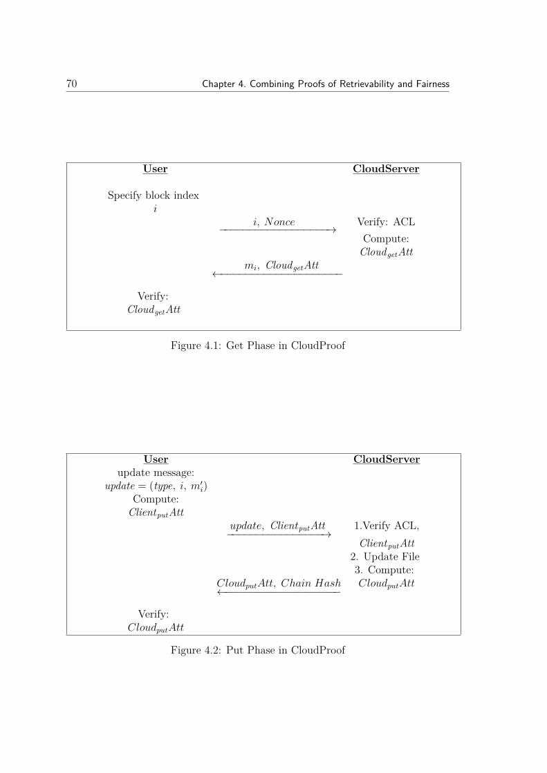
70 Chapter 4. Combining Proofs of Retrievability and Fairness
User CloudServer
Specify block indexi
i, Nonce−−−−−−−−−−−−−−−−−−→ Verify: ACLCompute:
CloudgetAttmi, CloudgetAtt
←−−−−−−−−−−−−−−−−−−−−
Verify:CloudgetAtt
Figure 4.1: Get Phase in CloudProof
User CloudServerupdate message:
update = (type, i, m′i)Compute:
ClientputAttupdate, ClientputAtt−−−−−−−−−−−−−−−−→
1.Verify ACL,ClientputAtt
2. Update File3. Compute:
CloudputAtt, Chain Hash←−−−−−−−−−−−−−−−−−−−CloudputAtt
Verify:CloudputAtt
Figure 4.2: Put Phase in CloudProof

4.2. DPOR Overview 71
In regard to the performance impact, the total storage overhead per data block
in CloudProof depends on which type of signature is used. This could be RSA
signature (1024 bits) or BLS signature (170 bits). Of course, other signature
schemes could be used. In addition to the signature there is overhead for key
management of AES keys. According to Popa et al. [104], all attestations are
about 1300 bits (or 400 bits for BLS signatures).
To evaluate the time latency, Popa et al. [104] performed 50 reads and 50
writes to different data blocks with 4KB size and computed the average time for
each operation. They found that the main cause of the overhead in time resulted
from generating, verifying and handling the attestations; adding the chain hash
for freshness also added a small overhead. In total, the overhead of CloudProof
as compared to the no security case is about 0.07s overhead for small block reads
or writes, which corresponds to 17% latency overhead [104]. Most of the overhead
time is spent at the server side as follows. Each read or write request consists of
user preprocessing (0.5%), network time or communication cost for a round trip
(36%), cloud processing (62%), and user post-processing (1.5%).
In general, CloudProof is one system satisfying the majority of the security
requirements. However, it does not provide assurance on data availability, i.e., it
does not guarantee that the entire data is indeed stored by the cloud provider.
Our goal then is to provide a cloud storage architecture that extends CloudProof
in order to provide availability assurance, by incorporating a proof-of-storage pro-
tocol.
4.2 DPOR Overview
Wang et al. [125] introduced the Dynamic Proofs of Retrievability (DPOR) with
public verifiability. The main goal of DPOR is to allow a third party auditor (TPA)

72 Chapter 4. Combining Proofs of Retrievability and Fairness
TPA CloudServer
Generate random set:i, νii∈J
i, νii∈J−−−−−−−−−−−−−−−−→Compute:µ = ∑
νimii∈J
µ, σ, H(mi),Ωi, sigsk(H(R))←−−−−−−−−−−−−−−−−−−−−−−−−
σ = ∏i∈Jσνii
Compute R using :H(mi),Ωi
Verify sigsk(H(R))Verify
e(σ, g) ?= e( ∏i=1H(mi)νi · uµ, pk)
Figure 4.3: Default verification in DPOR [125]
to verify the integrity of the dynamic data stored in the cloud on behalf of the
data owner. The main idea behind this scheme is to manipulate the classic Merkle
Hash Tree (MHT) construction for block tag authentication. Before sending the
data file into the cloud storage, the data file is encoded using error-correcting code
(Reed-Solomon codes). As in Section 2.1.3, the use of the Reed-Solomon encoding
assures that the original file can be reconstructed from a subset of the blocks of
the encoded file. The next step is to break the encoded file into n blocks m1, ...mn.
Then authenticate each block i as follow: σi = (H(mi) ·umi)sk; where u is random
element. Both the data blocks mi and authenticators σi are sent to the cloud
server along with the root signature sigsk(H(R)).
Figure 4.3 shows the default verification process in the dynamic POR protocol.
In this process, the verifier specifies a random set of indices J and for each index
i ∈ J associate it with a random value ν. The verifier sends Q = (i, νi)i∈J as
a challenge message to the prover. The prover then generates the proof which
includes the following: σ = ∏i∈Jσνii , µ = ∑
νimii∈J
, the set of hashes in the Merkle

4.2. DPOR Overview 73
User CloudServer
1. Generate:σ′i = (H(m′i) · um
′i)sk
(UpdateMessage,i,m′i, σ′i)−−−−−−−−−−−−−−−−−−−−−→2. Update F and
Compute R′
R′, H(mi),Ωi, sigsk(H(R))←−−−−−−−−−−−−−−−−−−−−−−−−
3. Compute R using :H(mi),Ωi
4. Verify sigsk(H(R))5. Compute Rnewusing
H(m′i),ΩiVerfiy update using :
Rnew?= R′
sigsk(H(R′))−−−−−−−−−−−−−−−−−−→
6. Update RSignature
Figure 4.4: Dynamic Data Modification in DPOR [125]
Hash Tree (MHT) for the requested data blocks H(mi),Ωii∈J , and the root
signature sigsk(H(R)). The prover will send them to the verifier. The verifier
generates the new root R and checks that: e(sigsk(H(R)), g) ?= e(H(R), pk) and
then e(σ, g) ?= e( ∏i∈JH(mi)νi · uµ, pk) (see aggregated BLS signature in Section
2.1.4).
Figure 4.4 shows the dynamic data operations in DPOR (i.e. data inser-
tion, deletion and modification). Suppose that the user wants to update the
ith data block in the file F . First, the user will generates the new signature
σ′i = (H(m′i) · um′i)sk and sends to the cloud new data block m′i, the update
message, the index i, and the new signature σ′i. The cloud then will run the
ExecUpdate(F,Φ, update). In this step the cloud server will first store the new
data blockm′i. Then it will update the Merkle hash tree by adding the leaf (H(m′i))
instead of the leaf (H(mi)) (if the update message is to modify the block for ex-

74 Chapter 4. Combining Proofs of Retrievability and Fairness
ample). Lastly it will generate the new root R′. Then the server will send the
update proof R′, H(mi),Ωi, sigsk(H(R)) to the cloud user. At the user side, the
user will compute R using H(mi),Ωi and verify the sigsk(H(R)). If it succeeds,
the user will compute the new root Rnew from H(m′i),Ωi and verify the update
process by Rnew?= R′. If this succeeds, the user will send the signature of the new
root sigsk(H(R′)) to the cloud who will update the root signature.
The DPOR scheme relies on the error-correcting code which ensures that it
is possible to recover the original file given a subset of the encoded file with all
but negligible probability. From the security point of view, the security of the
DPOR scheme [125] relies on the secrecy of u. In fact, the verification process
in the original POS scheme is designed to ensure that the prover will never send
a fake messages [125]. This is because the MAC/signature scheme used for file
tags is unforgeable and the symmetric encryption scheme is semantically secure.
According to Wang et al. [125], the adversary could not compromise the pro-
posed DPOR scheme and cause the verifier to accept a fake proof-of-retrievability
protocol instance if these two conditions are met as follows.
1. If the signature scheme is existentially unforgeable.
2. If the computational Diffie-Hellman problem is difficult in bilinear groups.
In regard to performance, the DPOR scheme uses an error-correcting code rate
ρ in which if t part of the file is corrupted, by asking the proof for a constant c
blocks of the file, the verifier can detect any cloud misbehaviour with probability
p = 1 − (1 − t)c. Let t = 1 − ρ and the probability will be p = 1 − ρc. The use
of error-correcting code involves a storage overhead which needs to be considered
when outsourcing data storage. In addition, the DPOR scheme [125] involves
complexity overhead, which is resulting from computing the response (σ = ∏i∈Jσνii
and µ = ∑νimii∈J
) at the server side. Wang et al. [125] gave a performance example

4.3. Proposed Architecture 75
for DPOR as follows: when running the DPOR on file of 1 GB in size and a 4 KB
block size the computation time at the server side could be up to 13.42 ms.
In general, DPOR does satisfy the majority of the security requirements of
Section 3.3.2. However, it does not provide assurance of data freshness and fair-
ness. The next section shows how to provide a cloud storage architecture that
combines CloudProof and DPOR in order to provide assurance for all the security
requirements of the data storage in the cloud.
4.3 Proposed Architecture
We consider a cloud storage scenario where there are four kinds of parties involved:
the data owner, the cloud provider, clients and an optional third party auditor
(TPA). The data owner pays for the cloud storage service and sets the access
control policies. The cloud provider offers the data storage service for a fee. Clients
request and use the data from the cloud. In the cloud environment we assume that
there is no mutual trust between parties.
We now describe a new architecture which combines the idea of CloudProof
[104] and Dynamic Proofs Of Retrievability (DPOR) [125] as it provides data avail-
ability for dynamic data along with most of other security requirements (listed in
Table 3.4). The proposed POS architecture tackles the limitations of both schemes.
Thus, the limitation of CloudProof of being unable to check data availability at
the whole data set level is overcome by employing DPOR.
DPOR consists of the following protocols/algorithms:
1. KeyGen: is a randomized algorithm that is used to generate cryptographic
key material.
2. Encode: is used for encoding data before sending it to the remote storage.

76 Chapter 4. Combining Proofs of Retrievability and Fairness
DataD
ata
DataC
loud
Storage
Servers
Cloud S
ervice Provider
Clients
Data O
wner
1 .1Fi , Φ
i , Ke yBloc k
Ta ble ,
s ig(root)
2.1. Req
uest: get (i, N
once)
2.2. Response:E(mi ) + Cloud
get Att
+ chain hash
3.2. Req
uest: p
ut “update = type + E
k (m’i ) +
i + σ’I ” + Client
put A
tt
2.3. VERIFY
σi &
Cloudget A
tt
3.1Prep
areUpdate→
m’i
3.5 VerifyU
pdate(p
k,
update, P
update ) + V
ERIFY
Cloudput A
tt
Client sto
re all Cloud
get/put att. until end of
epoch
3.4. Response: Cloudput A
tt+ chain hash + P
update
4.1.sendall
Cloudatt.
@ epoch end4 .2 . upda te
ACL& Fam
ily
key bloc k @ epoc h end
4.3. Auditatt_cloud
for each block
@ epoch end
5.1. challenge request
message ‘chal’
5.3. Response ‘P’
3.3. Verify & ExecUpdate(F, Φ, update)
5.2. (P) ← GenProof (F, Φ, chal)
TP
A
3.6. new root's signature sig
sk (H(R'))
5.4. VerifyProof(pk, chal, P)
Data
Figure4.5:
ProposedArchitecture

4.3. Proposed Architecture 77
3. GenProof: the service responds to the client’s challenge request by generating
a proof which is sent to the verifier.
4. VerifyProof: upon receiving the proof from the service provider, the client
executes this protocol to verify the validity of the proof.
5. ExecUpdate: this protocol is used in dynamic schemes and is executed by the
cloud provider. This protocol may include a proof by the service provider of
the successful update of the data, so that the customer can verify the update
process.
6. VerifyUpdate: this is executed by the client in order to verify the proof sent
by the service provider after an update.
As in CloudProof, we consider different time periods or epochs. At the end of
each epoch the data owner or TPA performs a verification process to assure that
the cloud storage possesses its data. In this way we obtain a design that satisfies all
the desirable properties discussed in Chapter 3. Figure 4.5 describes the proposed
architecture and identifies its parties and the different protocols that are executed
between them.
Key Management: We assume that the data owner will divide the plaintext
data file into blocks F ′′ = m′′1,m′′2, ...,m′′n. Each data block is assigned to an
access control list (ACL) (which is a set of users and groups) and blocks with
similar ACL are grouped in a single block family. In addition, for each block family
there is a family key block that contains a secret (signing) key sk (known only to
clients with write access in the ACL), read access key k (known only to clients
with read access in the ACL), public (verification) key pk (known to all clients
and the cloud provider), version of pk and k keys, block version, and signature of
the owner. The data owner will create the family key block table, in which each

78 Chapter 4. Combining Proofs of Retrievability and Fairness
row in this table corresponds to an ACL (Figure 4.6). The data owner maintains
the key production while the key distribution process is offloaded to the cloud
service provider but in a verifiable way. The key distribution process involves two
cryptographic tools; broadcast encryption [18, 49] EF which is used to encrypt
the secret key (EF (sk)) and read access key (EF (k)). EF (k) which guarantees that
only allowed clients and groups in the ACL’s read set can decrypt the key and use
it to decrypt the blocks in the corresponding family. sk is used to generate update
signatures for blocks. EF (sk) guarantees that only users and groups in the ACL’s
write set can decrypt the key and use it to generate update signatures for blocks
in the corresponding family. The key rotation scheme is another cryptographic
tool which is used to generate a sequence of keys using an initial key with a secret
master key [70]. Thus, only the owner of the secret master key can produce the
next key in the sequence. Also, by using key rotation, the updated key allows
computing of old keys. Thus, there is no need to re-encrypt all encrypted data
blocks [104]. The data owner will keep the family key block table and every time
there is a change of membership, the data owner will re-encrypt the key and update
the family key block table.
Pre-Storage Processing: The data owner encodes each block in the data file
F ′′ using Reed-Solomon error correcting F ′ = encodeRS(F ′′). Then, each block
in F ′ is encrypted using the corresponding k of that block family; F = Ek(F ′) =
m1,m2, ...,mn. The data owner creates a Merkle Hash Tree (MHT) for each
block family. The MHT is constructed as a binary tree that consists of a root R
and leaf nodes which are an ordered set of hashes of the family data blocks H(mi).
MHT is used to authenticate the values of the data blocks (see Section 2.2). As
in DPOR [125], the leaf nodes are treated in the left-to-right sequence thus, any
data block (node) can be uniquely identified by following this sequence up to the

4.3. Proposed Architecture 79
root (Figure 2.2).
DPOR [125] uses BLS digital signature or RSA in such a way that multiple
signatures verification can be done very efficiently. Thus, for each block family
F , the data owner runs the signature generator algorithm (Φ, sigsk(H(R))) ←−
SigGen(sk, F ) which takes the signing key of the family (sk) and the encrypted
block family F and generates the signature set for this family Φ = σ1, σ2, ...., σn;
where σi ← (H(mi) · umi)sk for each family block mi; u← G is a random element
chosen by the data owner. What is happening in the proof here is that an aggregate
signature over blocks that have been challenged is being computed as part of the
proof (see Section 2.1.4). In addition, a signature of the root of the associated
MHT is generated sigsk(H(R)). Then, each block mi will be associated with its
signature σi and some metadata such as block version and version of k and pk;
bi = mi||block V er||k V er||pk V er||σi (Figure 4.6). Finally, the data owner sends
to the cloud storage the block family b1, b2, ...., bn, its signature set Φ, the family
key block table, and the root signature of this block family sigsk(H(R)) (Message
1.1 of Figure 4.5: Fi,Fi, Key Block Table, sig(root)).
Figure 4.6: Data block and family key block table sent to the cloud

80 Chapter 4. Combining Proofs of Retrievability and Fairness
sk
Figure 4.7: Attestations of Popa et al. [104]
Attestations: As in CloudProof [104] we build a hash chain from all data
changes and require signing from both parties on all updates. Thus, any mis-
behaviour could be detected and proved by exchanging attestations for each re-
quest or response between data owner, clients and cloud provider. The structure
of exchanged attestations includes metadata such as the block version and cur-
rent hash which are used to maintain the write-serialisability (exactly one write
for every version number) and the hash chain value which is used for freshness
(Figure 4.7). The hash chain is computed over the hash of the data in the current
attestation and the chain hash of the previous attestation. Thus it is a sequence
of hashes, which contains current attestation and all history of attestations of a
specific block as follows: chain hash = H(data, previous hash chain value). Thus,
if the sequence of attestations is broken this means there is a violation of freshness
property. In addition, during each epoch clients need to locally store all received
attestations and forward them to the data owner for auditing purposes at the end
of each epoch (Figure 4.5).
Get block: In the get (read) request for a specific data block, clients need to send
to the cloud provider the block index (i) for that block and a random nonce (Mes-
sage 2.1 of Figure 4.5: Request : get(i, Nonce)). The cloud provider will verify
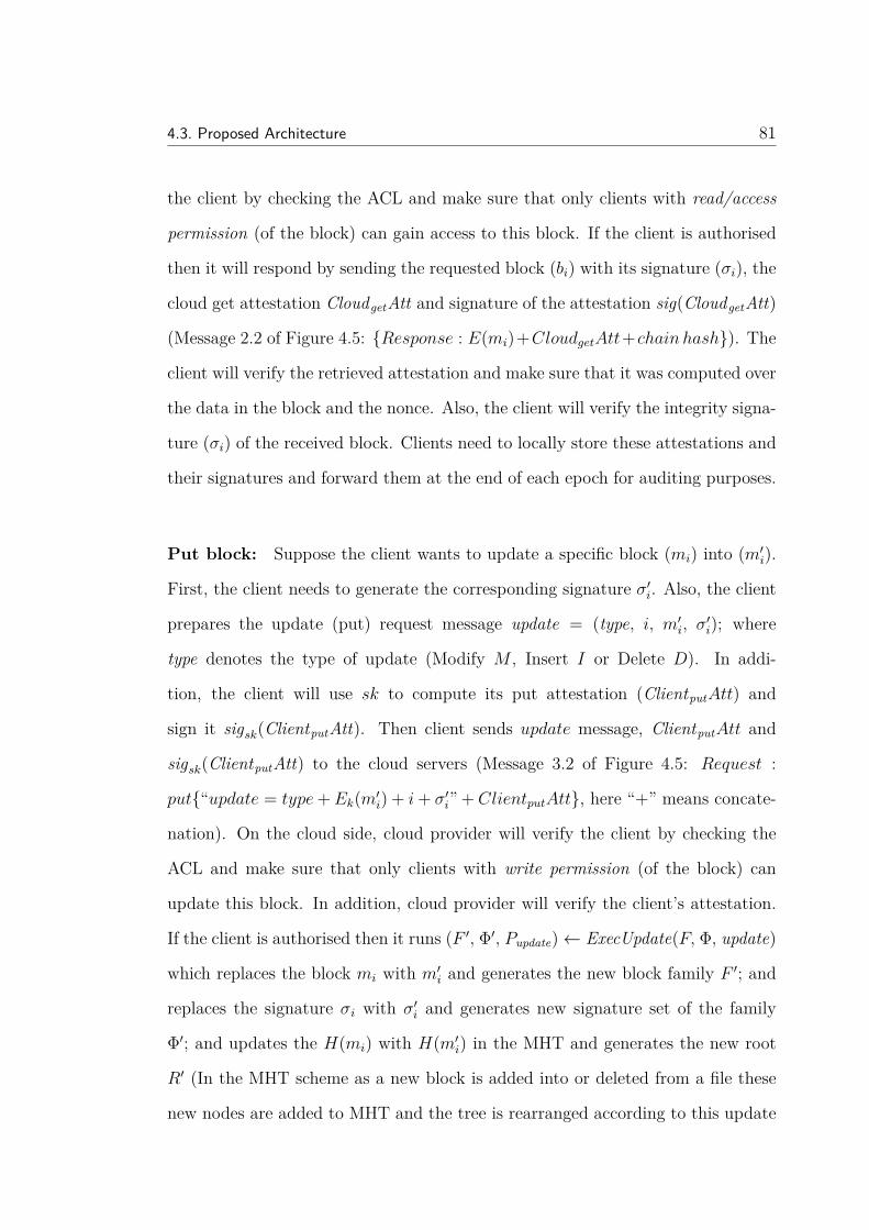
4.3. Proposed Architecture 81
the client by checking the ACL and make sure that only clients with read/access
permission (of the block) can gain access to this block. If the client is authorised
then it will respond by sending the requested block (bi) with its signature (σi), the
cloud get attestation CloudgetAtt and signature of the attestation sig(CloudgetAtt)
(Message 2.2 of Figure 4.5: Response : E(mi)+CloudgetAtt+chain hash). The
client will verify the retrieved attestation and make sure that it was computed over
the data in the block and the nonce. Also, the client will verify the integrity signa-
ture (σi) of the received block. Clients need to locally store these attestations and
their signatures and forward them at the end of each epoch for auditing purposes.
Put block: Suppose the client wants to update a specific block (mi) into (m′i).
First, the client needs to generate the corresponding signature σ′i. Also, the client
prepares the update (put) request message update = (type, i, m′i, σ′i); where
type denotes the type of update (Modify M , Insert I or Delete D). In addi-
tion, the client will use sk to compute its put attestation (ClientputAtt) and
sign it sigsk(ClientputAtt). Then client sends update message, ClientputAtt and
sigsk(ClientputAtt) to the cloud servers (Message 3.2 of Figure 4.5: Request :
put“update = type+Ek(m′i) + i+ σ′i” + ClientputAtt, here “+” means concate-
nation). On the cloud side, cloud provider will verify the client by checking the
ACL and make sure that only clients with write permission (of the block) can
update this block. In addition, cloud provider will verify the client’s attestation.
If the client is authorised then it runs (F ′, Φ′, Pupdate)← ExecUpdate(F, Φ, update)
which replaces the block mi with m′i and generates the new block family F ′; and
replaces the signature σi with σ′i and generates new signature set of the family
Φ′; and updates the H(mi) with H(m′i) in the MHT and generates the new root
R′ (In the MHT scheme as a new block is added into or deleted from a file these
new nodes are added to MHT and the tree is rearranged according to this update

82 Chapter 4. Combining Proofs of Retrievability and Fairness
as described in Section 2.2). The cloud responds to the update request by send-
ing a proof for the successful update (Pupdate = Ωi, H(mi), sigsk(H(R)), R′;
where Ωi is used for authentication of mi). Also, the cloud constructs the put
attestation (CloudputAtt) and signs it sigsk(CloudputAtt) and sends them to the
client (Messages 3.3: Verify & ExecUpdate(F,F, update) and 3.4: Response :
CloudputAtt+ chain hash+Pupdate of Figure 4.5). In addition, the cloud provider
will store the received client attestations to be used if any misbehaviour is de-
tected. The client verifies the cloud put attestation and checks the chain hash.
Also, the client verifies the received update proof by running this algorithm:
(TRUE , sigsk(H(R′))), FALSE ← VerifyUpdate(pk, update, Pupdate) which takes
pk, the old root’s signature sigsk(H(R)), the update message request (update), and
the received proof (Pupdate). If verification succeeds, it generates the new root’s
signature sigsk(H(R′)) for the new root R′ and sends it back to the cloud (Mes-
sages 3.5: V erifyUpdate(pk, update, Pupdate) + V ERIFY CloudputAtt and 3.6:
new root′s signature sigsk(H(R′)) of Figure 4.5). In addition, the client needs
to store all received cloud put attestation (CloudputAtt) and forward them to the
data owner for auditing purposes.
Auditing: The auditing process is carried out at the end of each epoch and
consists of two parts. In the first part the attestations produced within the given
epoch are verified as per CloudProof. In the second part, the integrity of the
whole data set is verified as in DPOR [125]. For each family block the TPA picks
random c-element subset I = s1, ..., sc. For each i ∈ I, the TPA selects a random
element νi. Then TPA sends the message chal which identifies which blocks to be
checked (chal = (i, νi)s1≤i≤sc) (Message 5.1: challenge requestmessage ‘chal’
of Figure 4.5). When the cloud provider receives the chal message, prover will
compute: 1. µ = ∑sci=s1 νimi; and 2. σ = ∏sc
i=s1 σνii ∈ G. The prover runs

4.4. Security Analysis 83
P ← GenProof (F, Φ, , chal) algorithm to generate the proof of integrity P =
µ, σ, H(mi),Ωis1≤i≤sc , sigsk(H(R)); where Ωi is the set of node siblings on
the path from the leaf i to the root R in the MHT (Messages 5.2 of Figure 4.5
(P )←GenProof(F,F, chal)). The verifier will verify the received proof by run-
ning this algorithm TRUE ,FALSE ← VerifyProof (pk, chal, P ). This way we
are able to check data availability at the whole file level.
4.4 Security Analysis
As described in Chapter 3, both schemes are considered to be secure and work
efficiently individually. We argue in this section how this new combination will
provide an assurance for all the desirable security requirements listed in Chapter 3.
Regarding the geographic assurance and the proof of replication, the next Chapters
will introduce a method to provide such assurance by combining the POS schemes
with the distance-bounding protocol.
Confidentiality: In regards to the data confidentiality, the proposed scheme is
assumed to maintain this property by allowing the data owner to encrypt the data
before sending it to the cloud storage. The key management process is maintained
by both the data owner and the cloud provider. The data owner maintains the
key generation while the key distribution process is offloaded to the cloud service
provider but in a verifiable way (e.g. broadcast encryption and key rotation).
To break the data confidentiality, an adversary aims to obtain some of the user’s
data, which is stored in the cloud. We expect that the adversary will be able to
eavesdrop all the messages going back and forward between the cloud provider,
data owner and the user. However, the data will always be kept encrypted and
will never be sent in the clear text.

84 Chapter 4. Combining Proofs of Retrievability and Fairness
Integrity: The integrity of the stored data will be preserved by two methods,
one at the block level and one at the whole file level. The first one is use of the
signed hash for each data block. For each put, a signed hash of the data block
needs to be provided. Thus, in the case of get data block (read), users verify the
signed hash of the retrieved data block. In general, the integrity signature on a
data block helps in detecting the integrity violations and exchanged attestations
prove these violations. The second method is to assure the integrity of the whole
data file by running the default verification process as described in Section 4.3
Auditing part ( Messages 5.1 to 5.4 of Figure 4.5).
In order to compromise the data integrity, the adversary aims to change the
stored data in the cloud storage without being detected. We expect the adversary
will be able to eavesdrop all the messages exchanged between the cloud provider,
data owner and the user. However, the data integrity is preserved by using the
signed hash for each data block. The data owner will be able to detect any integrity
modification by running the default verification process.
Availability: The data owner will be able to check the availability of the whole
data file at any time by running the default verification process (Messages 5.1 to
5.4 of Figure 4.5). If any misbehaviour is detected the data owner could rely on
the exchanged attestations to prove this violation.
We assume that the adversary (e.g. a malicious cloud provider) is capable of
accessing the whole stored data in the cloud and aims to compromise the avail-
ability property of the stored data. However, the data owner is able to detect any
misbehaviour and check the availability of the whole file by running the default
verification process at any time.

4.4. Security Analysis 85
Public Verifiability: The data owner (or any authorised party) is able to chal-
lenge the cloud server for correctness of stored data at any time. For instance,
messages 5.1 to 5.4 of Figure 4.5 show how the data owner could challenge the
cloud server to prove the correctness of stored data and force the cloud provider
to generate the proof and send it back to the data owner. The data owner then is
able to verify the retrieved proof.
If the data is not publicly verifiable, then the adversary aims to deceive the
user, whereas for a publicly verifiable scheme the adversary aims to deceive the
TPA. However, TPA is capable of verifying the correctness of the retrieved data.
Freshness: The proposed scheme provides an assurance of data freshness by
using hash chains. For each put and get attestation, the hash chain is computed
over the hash of the data in the current attestation and the hash value of the
previous attestation. Thus it is a sequence of hashes, which contains current
attestation and all history of attestations of a specific block as follow: chainhash =
H(data, previous chain hash). Thus, if the sequence of attestations is broken this
means there is a violation of freshness property.
In order to violate the data freshness, the adversary aims to have a different
version of the data from what should be stored in the cloud storage. We expect the
adversary will be able to access the data and able to eavesdrop all the messages
exchanged between the cloud provider, data owner and the user. However, the
data freshness property is protected by using the chain hash technique. Thus, any
missing data in the sequence of the attestations will be detected when auditing
the exchange attestations.
Fairness: The proposed architecture assures the fairness (or mutual non-repudiation)
by using the idea of exchanged attestations which allows data owner to detect and

86 Chapter 4. Combining Proofs of Retrievability and Fairness
prove any cloud misbehaviour. Each request and response for reading (get) and
writing (put) data is associated with an attestation. This attestation will be used
as a proof of any misbehaviour from both sides that need to store these attesta-
tions during each epoch. This will make each side accountable for his/her actions
in regards to the stored data.
In the other security properties we looked at, the adversary was basically a third
party looking into the protocol. However, when coming to fairness the adversary
is actually one of the protocol participants, be it either malicious cloud provider
or malicious user. But, the fairness property (or mutual non-repudiation) will be
protected by using the exchanged attestations for each request and response for
reading (get) and writing (put) of the stored data in the cloud. In fact, these
attestations will be used as a proof of good behaviour for all protocol participants.
4.5 Discussion
The main idea of the proposed scheme is to combine two existing POS schemes to
obtain a scheme which has the good properties of both its constituents. The pre-
vious Chapter (Section 3.5) provides a comparison between different POS schemes
and indicates which security requirements that are satisfied by them. It can be
seen that no single proposal that encompasses all security requirements identified
in table 3.4. CloudProof [104] is a POS scheme that satisfies the majority of the
security requirements (listed in Table 3.4). However, it does not provide assurance
on data availability, i.e. it does not guarantee that the entire data is indeed stored
by the cloud provider. The other POS scheme that satisfies most of desirable se-
curity requirements (listed in Table 3.4) is DPOR scheme [125]. However, it does
not address the fairness and freshness properties. Thus, the proposed scheme aims
to overcome the weaknesses of both schemes by extending the CloudProof in order

4.5. Discussion 87
to provide availability assurance. In this way we obtain a design that satisfies all
the identified desirable security properties listed in table 3.4.
Regarding complexity, the proposed scheme may incur communication and
computational complexity resulting from combining the two schemes. The compu-
tational complexity can be applied to both sides of the protocol. For instance, with
get process, the user needs to verify the retrieved attestations and integrity signa-
tures (σi) of the received blocks. Also, with put process, the user needs to generate
the corresponding signature σ′i and compute its put attestation (ClientputAtt) and
sign it sigsk(ClientputAtt). Moreover, the user needs to verify the cloud put attes-
tation and check the chain hash. Also, the user verifies the received update proof
and if verification succeeds, it generates the new root’s signature sigsk(H(R′)).
On the server side, with get process, cloud provider verifies the user by check-
ing the ACL and responds by sending the requested block (bi) with its signa-
ture (σi), the cloud get attestation CloudgetAtt and signature of the attestation
sig(CloudgetAtt). Also, with put process cloud provider runs ExecUpdate algorithm
and constructs the put attestation (CloudputAtt) and signs it sigsk(CloudputAtt).
In addition, with the default verification process at the end of each epoch, cloud
provider needs to compute: 1. µ = ∑sci=s1 νimi; and 2. σ = ∏sc
i=s1 σνii . Most of the
computational complexity here is resulted from the exponentiation involved (see
Section 2.1.5).
To evaluate the communication complexity, Popa et al. [104] did an experiment
by performing 50 reads and 50 writes to different data blocks with 4 KB size and
found that the average time needed for each operation is about 0.07 seconds and
36% of that is for the network time or communication cost for round trip. Also,
the signature schemes are relatively small. For example, BLS signature is 170
bits and is shorter than the RSA signature, which is 1024 bits long and provides

88 Chapter 4. Combining Proofs of Retrievability and Fairness
a comparable security level. In general, this issue could be resolved by utilising
more efficient technologies that may reduce the communication complexity.
4.6 Summary
This chapter introduced a cloud storage architecture that extends CloudProof in
order to provide availability assurance. This is accomplished by incorporating
a proof-of-storage protocol such as DPOR. The proposed POS architecture over-
comes the weaknesses of both schemes. In this way we obtain a design that satisfies
all the identified desirable security properties.

Chapter 5
GeoProof: Proofs of Geographic
Location for Cloud Computing
Environment
Chapter 3 elucidated the set of security properties that a secure cloud storage
application must fulfil. The geographic location of cloud data storage centres is
an important issue for many organisations and individuals due to the regulations
and laws that require data and operations to reside in specific geographic loca-
tions. Thus, data owners may need to ensure that their cloud providers do not
compromise the SLA contract and move their data into another geographic loca-
tion. This chapter introduces an architecture for a new approach for geographic
location assurance, which combines the proof-of-storage protocol (POS) and the
distance-bounding protocol. The client is able to check where their stored data is
located, without relying on the word of the cloud provider. This architecture aims
to achieve better security and more flexible geographic assurance within the en-
89

90 Chapter 5. GeoProof: Proofs of Geographic Location for Cloud Computing Environment
vironment of cloud computing. In particular, this chapter addresses the Research
Question 2 (outlined in Chapter 1):
“How can assurance of the geographic location of the data stored in the cloud
and SLA violations be detected be obtained?”
This chapter is organised as follows. The next section provides a brief intro-
duction. Following this in Section 5.2, we review the existing location assurance
schemes. Section 5.3 provides a short overview of the POS schemes. Section 5.4
introduces the proposed GeoProof architecture. Section 5.5 shows the idea of using
a dynamic POS scheme to be used in GeoProof protocol and what the outcomes
are of such combination in terms of performance. More discussion is provided in
Section 5.6. The final section in 5.7 draws conclusions.
5.1 Introduction
Cloud computing delivers a huge range of virtual and dynamically-scalable re-
sources including computation power and storage to users of Internet technologies.
These services could help private and government organisations to outsource their
data storage to cloud providers. However, many organisations will pay careful con-
sideration to where their data physically resides if they move to cloud computing.
The majority of the storage service providers claim in the service level agreement
(SLA) that they maintain the data availability and state that the data will reside
only in specific geographic locations. However, cloud service providers may violate
the SLA by intentionally or accidentally moving their clients’ data into remote data
centres that may be located outside the specified geographic boundaries seeking
cheaper IT costs.
Critical risks associated with cloud storage services need to be assessed and
managed. In fact, adopting any cloud solution requires an organisation’s CIO to

5.1. Introduction 91
address some legal questions such as, where is the cloud provider’s infrastructure
physically located (this includes third parties or sub-contractors) and where is the
data to be stored [46, 31]. The geographic location of the data has significant effects
on its confidentiality and privacy. This is because any data in the cloud storage
service is located in physical media, which is owned by someone (cloud provider
or subcontractor). This machine resides in one or more specific countries, which
have their own laws and regulations. As a result, the stored data will be subject
to these regulations [54, 71]. In addition, there are certain legislative requirements
on data and operations to remain in certain geographic locations [46, 31]. For
instance, in Australia it is not allowed by law to transfer any personal information
about individuals across national borders, unless transferred to a foreign country
that applies legal restrictions similar to Australia’s National Privacy Principles
[4]. Note that regarding the geographic location of the data, HIPAA, COBIT, ISO
27002 and NIST SP800-53 are important regulations and standards with which
the cloud provider needs to comply [32].
Today, there are some cloud storage providers that offer an option of a specified
geographic location for the data. For example, Amazon allows its customers to
locate and store their data in the European Union (EU) in order to offer better
performance and meet EU data storage regulations [5]. However, there is no
enforcement for location restrictions. Therefore, cloud providers may relocate,
either intentionally or accidentally, client’s data in remote storage. These storage
locations could be in undesirable countries. For this reason, cloud customers may
need to verify that their data are located in the same geographic location specified
at contract time and make sure that the cloud service provider continues to meet
their geographic location obligations.
This chapter proposes a new protocol (GeoProof), which is designed to provide
a geographic assurance for the data owners that their data remains in the same

92 Chapter 5. GeoProof: Proofs of Geographic Location for Cloud Computing Environment
physical location specified in the SLA. GeoProof combines the proof-of-storage pro-
tocol (POS) with the distance-bounding protocol. As seen in Chapter 3 (Section
3.5), POS is an interactive cryptographic protocol that allows the client to verify
the data without needing to download the whole data. The distance-bounding
protocol is an authentication protocol between a verifier and a prover, in which
the verifier can verify the claimed identity and physical location of the prover.
The GeoProof protocol combines the POS scheme with a timing based distance-
bounding protocol. Specifically, we employ the MAC-based variant of the POS of
Juels and Kaliski [69] and time the multi-round challenge-response phase of the
protocol to ensure that the data is located at the specified location. This allows
the client to check where their storage data is located, without relying on the word
of the cloud provider.
5.2 Review of Location Assurance
We first consider two existing techniques that can be used to verify the geographic
location of a remote host: distance-bounding protocols and geolocation schemes.
5.2.1 Distance-bounding protocols
A distance-bounding protocol is an authentication protocol between a verifier V
and a prover P, in which V can verify the claimed identity and physical location of
P. This protocol may be used to monitor the geographic location of the remotely
stored data by bounding the physical distance by timing a round trip time (RTT )
between sending out challenge bits and receiving back the corresponding response
bits. In general, distance bounding protocol involves three phases: initialisation
phase, distance-bounding phase (or exchange phase) and verification phase (Figure
5.1). In the initialisation phase, both the prover and verifier share a common secret

5.2. Review of Location Assurance 93
value s and key K. Also, both sides exchange their identification and a random
nonce N, which will be used to create their own string. This phase is not time
critical. The distance-bounding phase is time critical and involves a sequence of
challenge-response bit exchanges for a specific number j (j is a security parameter).
The verifier selects j random challenges (c1, c2, ...cj) and sends them to the prover.
For each sent challenge, the verifier starts the clock. For each challenge, the prover
on the other side generates the responses (r1, r2, ...rj) and sends them one-by-one
to the verifier. Upon receiving the response rj, the verifier stops the clock and
calculates the round trip time 4tj [13]. The verification phase involves verifying
the response rj and checking that the round trip time is in the allowed range
4tj ≤ 4tmax.
Brands and Chaum [25] were the first to propose distance-bounding protocol in
order to protect against the mafia fraud in which the adversary (for both V and P)
is sitting between the real V and P. However, this protocol does not consider the
case when the prover is not trusted (terrorist attack) and may fool V by allowing a
fake prover P that is physically close to V and can run distance-bounding protocol
with V on behalf of P. Note that in our application the verifier (user) does not
trust the prover (cloud provider). According to Reid et al. [107], the first distance-
bounding protocol that provides protection against a terrorist attack is the one
provided by Bussard [26]. However, this protocol is public-key based and involves
expensive computation and implementation [107].
Hancke and Kuhn [67] introduced a distance-bounding protocol that is based
on a symmetric-key identification method (Figure 5.2). In this protocol, the ini-
tialisation phase requires that both the prover and verifier share a common secret
value s and before they start the distance bounding protocol, they need to ex-
change random nonces rA and rB. Then a keyed hash function H is applied to
the concatenation of the nonces rA and rB to get d. After that, d is split into

94 Chapter 5. GeoProof: Proofs of Geographic Location for Cloud Computing Environment
two n-bit strings l and r. The distance-bounding phase then starts by sending a
challenge bit αi. The timing clock then starts and continues until a response from
the corresponding bit βi received. The prover needs to respond by ith bit of l if
αi = 0, and the ith bit of r if αi = 1. The verification process includes checking
the received bit βi and checking the round trip time RTT 4ti is not larger than
the allowed time 4tmax. However, Hancke and Kuhn’s protocol does not consider
the relay (terrorist) attack when the prover P sends a copy of the secret message
s to a closer fake prover P and allows him to run the distance-bounding protocol
with V [107].
Verifier (V) Prover (P)Shared message s Shared message s
and key k and key kInitialisation PhaseIDV , nonceNV −−−−−−−−−−−−−−−−−−−−−−−−−−→
IDP , nonceNP←−−−−−−−−−−−−−−−−−−−−−−−−−−
Exchange Phase
For i = 1to jdo:
Start clock: ∆ti ci−−−−−−−−−−−−−−−−−−−−−−−→
Stop clock: ∆ti ri←−−−−−−−−−−−−−−−−−−−−−−−END For
Verification Phase
Verify riVerify ∆ti ≤ ∆tmax
Figure 5.1: A general view of distance bounding protocols

5.2. Review of Location Assurance 95
Shared information: secret key sVerifier (V) Prover (P)
Initialisation Phase
NV ← 0, 1m NP ← 0, 1md← H(s,NP ||NV ) nonceNV −−−−−−−−−−−−−−−−−−−−−−→
d← H(s,NP ||NV )l← β1||....||βn l← β1||....||βn
r ← βn+1||....||β2n nonceNP←−−−−−−−−−−−−−−−−−−−−−−r ← βn+1||....||β2n
α← 0, 1n
Exchange Phase
For i = 1to ndo:
Start clock: ∆ti αi−−−−−−−−−−−−−−−−−−−−−−−→βi ← li:αi=0
ri:αi=1Stop clock: ∆ti βi←−−−−−−−−−−−−−−−−−−−−−−−
END For
Check βiCheck ∆ti ≤ ∆tmax
Figure 5.2: Hancke and Kuhn’s distance bounding protocol [67]
Reid et al. [107] enhanced Hancke and Kuhn’s distance-bounding protocol to
protect against terrorist attack. They made it a requirement to exchange identities
of both V and P in the initialisation phase. In addition, both V and P need to
use the key derivation function KDF to create the encryption key k, which will be
used to encrypt the shared secret message s (Figure 5.3).
In addition, a number of distance-bounding protocols have been proposed in
recent years in order to improve security levels against mafia and terrorist attacks.
Examples of such protocols include [90, 105, 116, 73, 40, 50, 72, 87, 122, 93, 101,
76, 77].
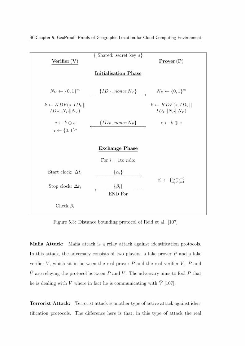
96 Chapter 5. GeoProof: Proofs of Geographic Location for Cloud Computing Environment
Shared: secret key sVerifier (V) Prover (P)
Initialisation Phase
NV ← 0, 1m IDV , nonceNV −−−−−−−−−−−−−−−−−−−→NP ← 0, 1m
k ← KDF (s, IDV || k ← KDF (s, IDV ||IDP ||NP ||NV ) IDP ||NP ||NV )
c← k ⊕ s IDP , nonceNP←−−−−−−−−−−−−−−−−−−−c← k ⊕ s
α← 0, 1n
Exchange Phase
For i = 1to ndo:
Start clock: ∆ti αi−−−−−−−−−−−−−−−−→βi ← ci:αi=0
ki:αi=1Stop clock: ∆ti βi←−−−−−−−−−−−−−−−−
END For
Check βi
Figure 5.3: Distance bounding protocol of Reid et al. [107]
Mafia Attack: Mafia attack is a relay attack against identification protocols.
In this attack, the adversary consists of two players; a fake prover P and a fake
verifier V , which sit in between the real prover P and the real verifier V . P and
V are relaying the protocol between P and V . The adversary aims to fool P that
he is dealing with V where in fact he is communicating with V [107].
Terrorist Attack: Terrorist attack is another type of active attack against iden-
tification protocols. The difference here is that, in this type of attack the real

5.2. Review of Location Assurance 97
prover P is one of the players. P intentionally cooperates with P and V in order
to fool the verifier V about the P ′s location.
Limitations of Distance-Bounding Protocols: Distance-Bounding protocols
are proximity protocols which rely on very fast wireless communication (e.g. Radio
Frequency (RF) security devices). In fact, the RTT resulting from this protocol is
then divided into twice the speed of light as these protocols are based on the fact
that the travel speed of radio waves is very similar to the speed of light (3 × 10⁸
m/s). For this reason, the time latency in them is very sensitive and any delay
introduced will be multiplied by the speed of light in order to find the distance.
Generally speaking, the timing error of 1 ms corresponds to a distance error of1×3×108
2 = 150 km (divide by 2 as it is RTT ).
In our GeoProof scheme, we will use the basic idea of a distance-bounding
protocol in which the verifier V will time the RTT from sending the request until
receiving the response. The majority of distance-bounding protocols were designed
to assure the physical location of clients or hosts (machines) and not the actual
stored data. However, in our GeoProof scheme, we are only concerned about
assuring the geographic location of the data itself with a main assumption that
the cloud provider is malicious and could intentionally or accidentally move the
data into somewhere else ( i.e. location relay attack as in Section 5.4.3). For
this reason, we will use the basic idea of distance-bounding protocol, which is the
timing phase only and where the exchanged bits are the actual stored data blocks
(Section 5.4.2).
5.2.2 Geolocation schemes
Geolocation schemes are another example of timing-based protocols that are used
to triangulate Internet hosts. The communication medium is not Radio Frequency

98 Chapter 5. GeoProof: Proofs of Geographic Location for Cloud Computing Environment
(RF) anymore. Instead, geolocation schemes are running in Internet media which
makes the location verification very rough. In general, geolocation schemes could
be classified into two types: measurement-based and IP address mapping based
[44].
Measurement-based geolocation: These schemes usually measure the physi-
cal location of a host by measuring the network delays between server and hosts. In
many cases, these measurements are based on the previous knowledge of position-
ing information of trusted reference hosts (landmarks) that are located close to the
host of interest. There are two types of reference landmarks: real measurements
and servers from experimental labs such as PlanetLab [3]. In fact, the measure-
ment accuracy of such schemes is dependent on the number of reference landmarks
used [44]. Examples of measurement-based geolocation schemes include:
1. GeoPing [98]: GeoPing locates the required host by measuring the delay
in time between required host and several known locations. It uses a ready-
made database of delay measurements from fixed locations into several target
machines.
2. Octant [130]: Octant is designed to identify the potential area where the
required node may be located. It calculates the network latency between a
landmark and a target and is based on the fact that the speed of light in
fiber is 2/3 the speed of light.
3. Topology Based Geolocation (TBG) [74]: TBG considers the network topol-
ogy and the time delay information in order to estimate the host’s geographic
location. In this scheme, the landmarks issue traceroute probes to each other
and the target. The topology network information is observed from the en-
tire set of traceroute from landmarks to other landmarks and from landmarks

5.2. Review of Location Assurance 99
to the target.
IP address mapping based geolocation: This type of geolocation scheme
relies on the use of the IP address of the target host and maps its relevant loca-
tion. These schemes are based on the DNS names of the host. They predict the
geographic location from the DNS names. However, with various incomplete and
outdated DNS databases, the IP address mapping is still more challenging [98].
Examples of IP address mapping based geolocation include:
1. GeoTrack [98]: the first step in GeoTrack is to traceroute the target host. It
then uses the result and identifies all domain names of intermediate routers
on the network path. After that, GeoTrack uses the domain name of these
machines and tries to estimates the geographic location of this target host
by the domain name itself.
2. GeoCluster [98]: the main idea of GeoCluster is to determine the geographic
location of the target hosts by using the Border Gateway Protocol (BGP)
routing information. Then, GeoCluster estimates the geographic location by
combining the BGP information with its IP-to-location mapping informa-
tion.
In general, many of the geolocation techniques lack accuracy and flexibility. For
instance, they provide location estimates with worst-case errors of over 1000 km
[74]. In addition, these schemes are used to determine the location of multiple
hosts, but in our case (cloud) we only focus to assure the location of one server
(the data storage if we assume that the data is in one machine and not distributed).
Most importantly, all known geolocation schemes have weak security as they do not
consider the adversarial target and do not assume that the prover (cloud provider)
is malicious. In our research we are interested in locating the data in the Internet

100Chapter 5. GeoProof: Proofs of Geographic Location for Cloud Computing Environment
and do consider the host as malicious. Our key objective is that using GeoProof
we can verify that given data resides in a specific location.
5.3 Proof-of-Storage (POS)
As discussed in the previous chapter (Section 4.4), proof-of-storage (POS) protocols
have been introduced as a means of enabling cloud service customers to verify the
correct behaviour of cloud service providers. The main idea behind the POS
schemes is to allow the users (or data owner) to verify the data while stored
remotely without the need of retrieving the whole data. The advantage of using
the POS protocols is that the size of the exchanged information between the verifier
and the prover is very small and may even be independent of the size of stored
data [30].
In GeoProof and for simplicity, we will use the idea of the MAC based POR
scheme by Juels and Kaliski [69] (Section 3.5.1). The Juels and Kaliski [69] scheme
is designed to deal with the static data but GeoProof could be modified to encom-
pass other POS schemes that support verifying dynamic data such as dynamic
proof of retrievability (DPOR) by Wang et al. [125] (Section 5.5).
Recently, there has been some literature addressing the issue of location as-
surance in the cloud. Peterson et al. presented a position paper [103] that talks
about how to combine a proof-of-storage protocol with geolocation, but without
giving any details. Also, Benson et al. [15] discuss how to obtain assurance that a
cloud storage provider replicates the data in diverse geolocations. Neither of these
papers gives any details regarding usage of distance-bounding protocols or how to
appropriately and securely integrate them into a proof-of-storage scheme.

5.4. Proposed GeoProof Architecture 101
5.4 Proposed GeoProof Architecture
The main idea of the GeoProof protocol is to combine the POS scheme with a
timing-based distance-bounding protocol. Specifically, we employ the MAC-based
variant of the POR of Juels and Kaliski [69] and time the multi-round challenge-
response phase of the protocol to ensure that the data is located in specified
location.
..chali ..
.. respi ..
Figure 5.4: Proposed GeoProof Architecture
In this proposed GeoProof scheme a device (GPS enabled to ensure physi-
cal location of this device) will be attached to the local network of the service

102Chapter 5. GeoProof: Proofs of Geographic Location for Cloud Computing Environment
provider. We assume that this device is tamper proof, which means no one can
modify this device, including the service provider. This device will be used to
run the distance-bounding protocol with the distributed data centres. A third
party auditor (TPA) communicates with this device in order to obtain assurance
regarding the geographic location on behalf of the data owner. The TPA knows
the secret key used to verify the MAC tags associated to the data. The tamper
proof device, which we called the verifier (Figure 5.4), has a private key which it
uses to sign the transcript of the distance bounding protocol, together with some
additional data, which is then sent to the TPA.
Importantly, there is an argument about how to prevent the cloud provider
from keeping backup copies elsewhere, outside the tested location. Dijk et al.
[123] use what they call ’economic’ arguments to justify that the cloud provider
will not take any actions that cause it economic loss. So, for example, they argue
that the cloud provider would not keep extra copies if they are not needed. In
their case they want to prove that the cloud provider keeps the data encrypted,
but they cannot prove that the provider also keeps unencrypted copies. Similarly,
although we cannot use the proposed protocol to show that there are not other
copies elsewhere, this would be counter-productive for the cloud provider.
5.4.1 Setup phase
As in the POR [69], the data file is prepared before it is sent to the cloud storage.
The setup process involves five steps as follows:
1. The file F is divided into blocks F = B1, B2, ....Bn with a specific block
size `B = |Bi|. Following the example given in [69], `B= 128 bits; as it is the
size of an AES block. Of course, if a different encryption algorithm is used
with a different block size, then it will be appropriate to choose different

5.4. Proposed GeoProof Architecture 103
variable `B.
2. Then, blocks in F are grouped into k-block chunks and for each chunk of
blocks an error correcting code is applied resulting in F ′. Reed-Solomon error
correcting codes are suitable for this purpose. As in [69], for the purpose of
this research, we consider the adapted (255, 223, 32)-Reed-Solomon code
over GF [2128]. The chunk size in this code is 255 blocks. This step increases
the original size of the file by about 14% (Section 2.1.3).
3. The updated file F ′ is encrypted using a symmetric-key cipher and the result
is F ′′ = EK(F ′).
4. The next step is to reorder the blocks of F ′′ using a pseudorandom permu-
tation (PRP) [81]. The result from this step is the file F ′′′.
5. The final step in the setup phase is to use the MAC. The file F ′′′ is di-
vided into sequentially indexed segments of v blocks (e.g. v = 5 blocks);
S1, S2, ....Sn. For each segment, the MAC is computed as follows: τi =
MACK′ (Si, i, fid); where i is the segment index and fid is the file ID. For
example, the size of the MAC block can be small (e.g. 20 bits) since the MAC
could be truncated and it will be the aggregate effect on multiple blocks that
is being measured (Section 2.1.4). Note that the protocol involves the verifi-
cation of many tags, hence the output size can be small. Lastly, each segment
is embedded with its MAC and the result is the file F ready to be stored in
the cloud. Based on the assumption of block size `B = 128 bits, v = 5 and
MAC length `τ = 20 bits; the segment size will be `S = (128× 5) + 20 = 660
bits.

104Chapter 5. GeoProof: Proofs of Geographic Location for Cloud Computing Environment
5.4.2 GeoProof protocol
In GeoProof protocol (Figure 5.5), the verifier V sends a large file F , computed
during the setup phase, that consists of a set of segments (S1, S2, ....Sn) to the
prover P (cloud). Each segment Si is associated with its tag value τi. The GeoProof
protocol could be run every specific time period (e.g. once daily). GeoProof
protocol is started when the TPA sends the total number of segments n of F , the
number of segments to be checked k, and a random nonce N to the verifier (V ).
The verifier V then, generates the challenge message c, which is simply a random
set of indexes c = c1, c2, ...., ck ⊆ 1, 2, ...., n. Then the distance-bounding
protocol is run between V and P consisting of k rounds. For j = 1 to k, V sends
the index cj and starts the timing clock 4tj. When P receives the request it starts
the look up process for this block and responds by sending back the data segment
and the tag Scj||τcj
. Let the time taken for looking up the specific block be 4tLj.
Upon receiving the response, V stops the timing clock and the time taken for this
trip is 4tj = 4tV Pj+4tLj
; where 4tV Pjis the actual round trip travelling time
between V and P without the look up time. After running the distance-bounding
protocol for k times, V generates the response R which includes the time values
4t = 4t1,4t2, ...,4tk, the challenge message c, all requested segments with its
tags embedded in it Scjj=1j=k, the nonce N , and V ’s GPS position Posv (Figure
5.5). Then, V signs the whole response R using its private key SK and sends R
and SigSK(R) back to TPA.
Example: Assume that we have a 2 gigabyte file F that we want to store in the
cloud. Let us say that the ideal block size is `B = 128 bits as it is the size of an
AES block. Of course, if a different encryption algorithm is used with a different
block size, then it will be appropriate to choose a different variable l. Then, F is
divided into b = 227 blocks. Then, for each chunk of data (223 blocks) we apply

5.4. Proposed GeoProof Architecture 105
j
.. j ..
.. cj ..
1 2 k
1 2 k
j1
2
n
.. n, k, N ..
1 2 k
.. cj j=1..k v
SK ..
SK
cj K’ cj
max
v
Fj=1 to k do:
Figure 5.5: GeoProof Protocol

106Chapter 5. GeoProof: Proofs of Geographic Location for Cloud Computing Environment
an error correcting code (Section 2.1.3). This will expand the file size by about
14% and the size of the new file F ′ equals b′ = 153, 008, 209 blocks. Then the file
F ′ is encrypted (F ′′ = EK(F ′)). After that, we apply the permutation function
on file F ′′ and produce F ′′′. The last step is the MACing process in which F ′′′ is
divided into sequentially indexed segments with a size of 5 blocks. With a 20-bit
MAC, the incremental file expansion due to MACing would be only about 2.5%.
In total, the space overhead resulting from both error correcting and MACing is
about 16.5%.
Verification process: The TPA (A) does the verification process which involves
the following steps:
1. Verify the signature SigSK(R).
2. Verify V ’s GPS position Posv.
3. Check that τcj= MACK(Scj
, cj, fid) for each cj. According to Juels and
Kaliski [69], an adversary cannot feasibly identify a single MACed segment.
4. Find the maximum time4t′ = max(4t1,4t2, ...,4tk) and check that4t′ ≤
4tmax. 4tmax depends on the latency characteristics of the network and
computing equipment as is further discussed in Sections 5.4.4 and 5.4.5.
5.4.3 Security analysis
The adversary (dishonest cloud provider) aims to achieve two main goals; to com-
promise the data integrity of the data stored in the cloud without being detected
and the second one is to fool the verifier that the stored data is located in the same
physical location stated in the SLA. The data integrity is preserved according to
the original POS scheme used and the location assurance is mainly preserved by
the distance-bounding protocol.

5.4. Proposed GeoProof Architecture 107
Integrity assurance: Juels and Kaliski [69] provide a detailed analysis of the
probability of the prover compromising the integrity of the file without being de-
tected. Based on the example parameters discussed above, if an adversary corrupts
0.5% of the data blocks of the file, then the probability that the adversary could
make the file irretrievable is less than 1 in 200, 000. In POR the detection of file
corruption is a cumulative process. Assume that we have a file with 1, 000, 000
segments embedded and the verifier can query 1, 000 segments in each challenge.
Based on [69], POR protocol provides a high probability of detecting adversarial
corruption of the file in each challenge.
Distance-bounding assurance: According to the discussion in Sections 5.4.4
and 5.4.5, we may consider an acceptable upper-bound for the round trip delay
4tV P of 3 ms, and a maximum look up time 4tL of 13 ms. As a result, the
expected round trip time for a packet to travel between V and P must be less
than 4tmax ≈16 ms.
chal
resp
VP
L
LAN INET
LB LW
PP’
LB LW
max i LW
i LB PP’
LB
Figure 5.6: Relay Attack

108Chapter 5. GeoProof: Proofs of Geographic Location for Cloud Computing Environment
We can categorise hard disks into two types: best hard disks with very low look
up time 4tLB, and worst hard disks with high look up time 4tLW ; where4tLB
4tLW . Figure 5.6 discusses the relay attack scenario in which the adversary P
(cloud provider) tries to move the stored data into a fraudulent location P ′ which
is accessible via the Internet. In this scenario, P is not involved in any look up
process, it just passes any request from V into P ′ . In addition, assume that the
remote data centres run high performance hard disks with very low look up time
4tLB ' 5.406 ms corresponding to a HDD of IBM (36Z15); as discussed in Section
5.4.4. Moreover, assume that an upper-bound for the speed of the Internet of 49 the
speed of light; as discussed in Section 5.4.6. Then the maximum distance between
the verifier and the remote data centres is 49 3× 10² km/ms× 5.406 ms = 720 km/2
(for the round trip) = 360 km.
In practice, this number is much smaller for many reasons. For instance, it is
unlikely that the service provider would want to invest a lot of money to place
the data in a remote data centre with such high performance equipments and
consequent required high budget. Furthermore, these measurements could be made
at the contract time at the place where the data centre is located and could be
based on the concrete settings of the data centre and the characteristics of the data
centre (e.g. LAN latency and look up latency). Thus, we identify the acceptable
time delay and these measurements could be tested every time using our proposed
GeoProof protocol.
In case of relay attack (Figure 5.6), the cloud provider will need to use the
Internet in order to pass the request into the fraudulent location P . However,
the use of Internet involves an extra delay, which will affect the physical distance
travelled and will be detected by the verifier (Section 5.4.6). Thus, the only way
that the adversary could compromise the scheme is by having a dedicated fast
communication connection with the remote data centres in order to respond to

5.4. Proposed GeoProof Architecture 109
the verifier’s requests in the permissible time. However, it is unlikely that the
service provider would want to invest a lot of money to place the data in a remote
data centre with such high performance and required high budget.
We assume that the verifier V is GPS enabled, and we need to rely on the
GPS position of this device. However, the GPS signal may be manipulated by
the provider. In fact, the GPS satellite simulators can spoof the GPS signal by
producing a fake satellite radio signal that is much stronger than the normal GPS
signal. The GPS receivers can be spoofed by these fake signals [29]. Thus, for extra
assurance we may want to verify the position of V. This is easier than verifying
the position of P, because we trust that V will follow the protocol. For better
accuracy, we could consider the triangulation of V from multiple landmarks [120].
This may include some challenges as the verifier is located in the same network
that is controlled by the prover, thus the attacker may introduce delays to the
communication paths between these multiple auditors.
5.4.4 Hard disk latency
Hard disk drives (HDD) are used on the cloud provider side to store the client’s
data. One important issue that determines the performance of HDD is the ro-
tational speed of the platters (RPM) [99, 42, 121]. The time taken by the hard
disk drive in order to look up specific data is important when distance-bounding
protocol is involved. In fact, any very small amount of time has its implications
on the distance and how far the data is from the verifier. The look up latency 4tL
is composed of three determinants [42]: the seek time 4tseek, rotational latency
4trotate and data transfer time 4ttransfer.
4tL = 4tseek +4trotate +4ttransfer
1. 4tseek: is the time that the HDD takes to position the proper sector under

110Chapter 5. GeoProof: Proofs of Geographic Location for Cloud Computing Environment
the read/write head.
2. 4trotate: is the rotational latency which is the waiting time needed by the
disk head to spin the disk platter until it arrives to the first required sector.
3. 4ttransfer: is the data transfer time and it is composed of two variables.
The first one is the Internal Data Rate (IDR) which is the transfer rate
between the disk storage media and the disk cache. The second variable is
the External Data Rate(EDR), which is the transfer rate between the disk
cache and the memory. In general, IDR is the one used for measuring the
HDD data transfer rate.
Table 5.1: Latency for different HDD [42]
Type IBM36Z15
IBM73LZX
WD2500JD
IBM40GNX
HitachiDK23DA
RPM 15,000 10,000 7,200 5,400 4,200avg(4tseek) ms 3.4 4.9 8.9 12 13avg(4trotate) ms 2 3 4.2 5.5 7.1avg(IDR) Mb/s 55 53 93.5 25 ~ 34.7
Table 5.1 shows the RPM and latency for five different HDD. It is clear that
the RPM has a significant effect on the look up latency 4tL where the higher the
RPM speed, the lower the look up latency. However, the high increase in RPM of
the disk drives is associated with other problems such as high temperature, power
consumption, noise and vibration.
In the cloud computing environment, we assume that the cloud storage provider
is using an average HDD in terms of RPM; for example the Western Digital
(WD2500JD). This product has characteristics of 7, 200 RPM, the seek time4tseek
is 8.9 ms, the rotational latency 4trotate is 4.2 ms, and the internal transfer time of
512 bytes is 4ttransfer = 512×8748×103 = 5.48×10⁻³ ms; where 748 is the media transfer

5.4. Proposed GeoProof Architecture 111
rate. Thus the average look up latency 4tL = 4tseek + 4trotate + 4ttransfer =
8.9 + 4.2 + 5.48× 10−3 = 13.1055 ms.
Consider a case where the cloud storage provider may want to deceive his
clients and store the data in remote storage in order to save money (the relay
attack scenario). We assume that the remote storage devices use an improved
HDD in terms of RPM; for example IBM (36Z15). The seek time 4tseek is 3.4
ms, the rotational latency 4trotate is 2 ms, and the internal transfer time of 512
bytes is 4ttransfer = 512×8647×103 = 6.33 × 10⁻³ ms; where 647 is the media transfer
rate . Thus, the average look up latency 4tL = 4tseek +4trotate +4ttransfer =
3.4 + 2 + 6.33× 10−3 = 5.406 ms .
5.4.5 LAN latency
In our GeoProof scheme, the verifier V is assumed to be placed in the same
local network of the cloud provider P (Figure 5.4). This assumption will help to
eliminate the Internet latency. Thus, the only network latency is expected from
the Local Area Network (LAN) and such delay is affected by the wiring media
used and the switching equipments used in between.
According to Percacci et al. [100], Wong et al. [130] and Katz-Bassett et
al.[74], digital information can travel in the optic fibre cables at a speed of 2/3 the
speed of light in a vacuum. So, if the optic fibre is used for cabling the network
in the LAN, then we expect that the data packet will travel at the speed of:
SLAN = 23 × 3× 105 km/s = 200 km/ms. This means that the round trip time (RTT )
needed for a packet to travel in LAN between V and P 4tV P is about 1 ms within
the range of 200 km.
One common method of networking workstations in LAN is the Ethernet which
uses copper cabling. The speed of the common Ethernet ranges from 100 Mbps for

112Chapter 5. GeoProof: Proofs of Geographic Location for Cloud Computing Environment
Table 5.2: LAN Latency within QUT
Machine# Location Distance (km) Latency(ms)
1 Same level 0 < 12 Same level 0.01 < 13 Same level 0.02 < 14 Same Campus 0.5 < 15 Other Campus 3.2 < 16 Same Campus 0.5 < 17 Other Campus 3.2 < 18 Other Campus 45 < 19 Other Campus 3.2 < 110 Other Campus 3.2 < 1
Fast Ethernet and 1000 Mbps for Gigabit Ethernet [79]. In general, there are two
types of time delays in Ethernet: the propagation time delay which depends on
the physical length of the network and the transmission time delay, which depends
on the message size [80]. In the worst case scenario, the propagation time delay
for the Ethernet is about 0.0256 ms. Lian et al. [80] indicate that the “Ethernet
has almost no delay at low network loads”.
For more justification, we ran a small experiment within the Queensland Uni-
versity of Technology (QUT) network. The experiment aim was to run the tracer-
oute (ping) command for different workstations with different destinations within
the QUT’s network. Table 5.2 indicates that the LAN latency in QUT’s network
is less than 1 ms in most cases.
For simplicity, in our proposed GeoProof scheme, we assumed that the LAN
latency is about 1 ms. However, the previous calculations do not consider the
delay that may result within the LAN network from switching equipments. To
remedy this problem, we require the cloud provider to place the verifier V very
close to the data storage.

5.4. Proposed GeoProof Architecture 113
Table 5.3: Internet Latency within Australia
URL Location ADSL2, Brisbane (AU)Dist.(km)† Latency (ms) km/ms
uq.edu.au Brisbane (AU) 8 18 0.44qut.edu.au Brisbane (AU) 12 20 0.6une.edu.au Armidale (AU) 350 26 13.46sydney.edu.au Sydney (AU) 722 34 21.24jcu.edu.au Townsville (AU) 1120 39 28.72mh.org.au Melbourne (AU) 1363 42 32.45rah.sa.gov.au Adelaide (AU) 1592 54 29.48utas.edu.au Hobart (AU) 1785 64 27.89uwa.edu.au Perth (AU) 3605 82 43.96
†Physical distance is calculated using “Google Maps Distance Calculator” [2]
5.4.6 Internet latency
The data packet travelling in the Internet could face high time delays due to the
huge amount of infrastructure used. In fact, this delay has a direct correlation
with the distance; as the distance increased, the time delay increased. According
to Katz-Bassett et al. [74], the speed of Internet is nearly 49 the speed of light; i.e.
49 3× 10² km/ms . So, in 3 ms, a packet can travel via the Internet for a distance of:49 3× 10² km/ms× 3 ms = 400/2 km (for the round trip) = 200 km or 66 km/ms.
The previous measurement was done in the US and may not necessarily trans-
late to other parts of the Internet and in fact our investigation indicates that is
not the case. Table 5.3 shows the Internet Latency within Australia. We used the
traceroute command to measure the RTT between a host located in Brisbane and
some other hosts around Australia. The physical distance between each pair of
hosts was measured using the online “Google Maps Distance Calculator” [2]. We
found that there is a positive relationship between the physical distance and the
Internet latency. Thus, as the physical distance increased the time delay increased.
Also, as physical distance increases, the delay/km decreases, but is always in the
bound of 66 km/ms.

114Chapter 5. GeoProof: Proofs of Geographic Location for Cloud Computing Environment
Setup
• File F = m1,m2, . . . ,mn.
• Φ = σi1≤i≤n.
• Data owner sends F,Φ, sigsk(H(R)) to cloud storage.
POS Phase
Verifier CloudServerStart clock: ∆ti i, νii∈J−−−−−−−−−−−−−→
µ = ∑νimii∈J
Stop clock: ∆ti P = µ, σ, H(mi),Ωi←−−−−−−−−−−−−−−−−−−−−σ = ∏
i∈Jσνii
Verification
Verify P
Figure 5.7: GeoProof with Dynamic POS (e.g. DPOR)
5.5 GeoProof for Dynamic Data
In the previous proposed GeoProof, the POS scheme is designed for the static or
archival data. This section shows the expected limitation when a dynamic POS
scheme (e.g. DPOR described in Section 4.2) is used to be combined with the tim-
ing phase in distance-bounding protocol. This includes running distance-bounding
protocol (timing phase) and challenging the cloud provider with random selected
block indexes. The cloud provider needs to perform significant computations to
generate the proof P at the cloud side. The whole process could be run as a multi-
round phase for each challenge. For each challenge-response, the verifier calculates
how long it takes to retrieve the requested proof.

5.6. Discussion 115
Performance analysis: This approach involves a significant time delay result-
ing from the computation overhead at server side for each challenge-response
round. For instance, the complexity overhead in DPOR [125] is resulted from
computing the response (µ = ∑νimii∈J
) and (σ = ∏i∈Jσνii ) at the server side. Wang
et al. [125] gave a performance example for DPOR as follows: when running the
DPOR on file of 1 GB in size and a 4 KB block size, the computation time could
be up to 13.42 ms. Note that, the request message (e.g. i, νii∈J) is independent
from the file size and thus it has no affect on the scalability.
5.6 Discussion
It is clear that the proposed scheme depends on GPS co-ordinates that have been
provided by the cloud provider. However, the cloud provider may manipulate the
GPS signal by producing a fake satellite radio signal that is much stronger than
the normal GPS signal [29]. To overcome this issue, we assume that the verifier is
a tamper proof device and for extra assurance we may want to verify the position
of V. This is easier than verifying the position of P, because we trust that V will
follow the protocol. For better accuracy, we could consider the triangulation of V
from multiple landmarks [120]. This may include some challenges as the verifier
is located in the same network that is controlled by the prover, thus the attacker
may introduce delays to the communication paths between these multiple auditors.
This issue may be resolved if using authentication along with the triangulation
process.
In regards to the experimental work of the proposed techniques, the scope of
the project did not allow extensive experimentation. This would be desirable in
future work to validate the proposed schemes.

116Chapter 5. GeoProof: Proofs of Geographic Location for Cloud Computing Environment
Ideally, doing experiments on real cloud services should be carried out in co-
operation with commercial cloud providers. This would require storage locations
to be set up at different sites. Accurate measurements of latency would need to
be made for a variety of locations and a statistical analysis carried out. How-
ever, doing experiments on real cloud services is potentially expensive and difficult
to carry out. For example, the need to have a GPS enabled device close to a
cloud provider’s premises is a major task and could face objection from the cloud
provider’s side.
Another possibility would be doing the experiments on simulated cloud services.
However, this would require some assumptions about the different latencies and
so may not give a realistic picture of what happens in practice. In addition,
simulations do not give an accurate representation of the timings which we require.
For this reason, the simulation cannot provide optimal results especially in the
cloud environment. Another important limitation is the lack of sufficient validation
and verification of simulation.
5.7 Summary
Geographic assurance is an example of the challenges for adopting the cloud com-
puting services. This is because some countries have flexible laws and regulations
that may affect the confidentiality and privacy of the stored data. Thus, data own-
ers may need to make sure that their cloud providers do not compromise the SLA
contract and move their data into another geographic location. We propose our
GeoProof protocol, which combines the proof-of-storage protocols and distance-
bounding protocols, in order to provide an assurance for the geographic location
in the cloud environment.
The next chapter will focus on how to enhance the GeoProof protocol and

5.7. Summary 117
minimise the time delay that may result from the server side computation.

118Chapter 5. GeoProof: Proofs of Geographic Location for Cloud Computing Environment

Chapter 6
Enhanced GeoProof: Improved
Geographic Assurance for Data in
the Cloud
Cloud users may want to be sure that their stored data has not been relocated
into unknown geographic regions that may compromise the security of their stored
data. Chapter 5 introduced the idea of combining proof-of-storage (POS) pro-
tocols with distance-bounding protocols to address this problem. However, the
proposed scheme involves unnecessary delay when utilising typical POS schemes
due to computational overhead at the server side. The aim of this chapter is to
improve the proposed GeoProof protocol by reducing the computation overhead
at the server side. We show how this can maintain the same level of security
while achieving more accurate geographic assurance. In particular, this chapter
addresses the Research Question 3 (outlined in Chapter 1):
“How to enhance GeoProof to encompasses the dynamic POS schemes and
119

120Chapter 6. Enhanced GeoProof: Improved Geographic Assurance for Data in the Cloud
reduce the extra time resulting from computational overhead at the server?”
This chapter is organised as follows. The next section provides an introduction.
Section 6.2 elucidates the limitations of the basic GeoProof. Section 6.3 provides
an overview of the generic structure of proof-of-storage schemes. Section 6.4 gives
details of the enhanced GeoProof and shows how it can be applied to sample
concrete protocols. This section also provides a security and efficiency analysis in
order to validate the usefulness of the proposal. The final section in 6.5 summarises
the chapter.
6.1 Introduction
Chapter 5 proposes a new protocol (GeoProof) which is designed to provide a
geographic assurance for data owners that their data remains in the same physical
location specified in the SLA. GeoProof combines the proof-of-storage protocol
(POS) with the distance-bounding protocol. Specifically, in Chapter 5 we employed
the MAC-based variant of the protocol of Juels and Kaliski [69] and time the multi-
round challenge-response phase of the protocol to ensure that the data is close-by
to the prover. This allows the client to check where their stored data is located,
without relying on the word of the cloud provider.
The proposed GeoProof protocol in Chapter 5 requires the same computational
overhead at the cloud side as is used in the underlying POS protocol in order to
compute the required proof and send it back to the verifier. This computational
overhead may incur a significant time delay, which will affect the accuracy of
the geographic location. Even a relatively small time delay is significant; using
measurements of Katz-Bassett et al. [74], we estimated that data could travel up
to 200 km in 3 ms, greatly degrading the accuracy of location estimates.
The aim of this chapter is to enhance the basic GeoProof protocol (Chapter

6.2. GeoProof Limitations 121
5) by reducing and delaying server side computation. The main idea is to avoid
or delay all significant computational parts of the proof at the provider side. This
will produce a saving in time for the server response, which will increase the
location accuracy of the stored data. The timing phase in the enhanced GeoProof
will minimise any possible time delay that may be caused by the computation
overhead on the server side. By applying our improvement to concrete protocols,
using parameters suggested by the authors of specific schemes, we show that we
can improve the accuracy of location of data by hundreds or even thousands of
kilometres depending on the complexity of the POS scheme in use. We also show
that our improvement does not undermine the security of the underlying POS
protocol.
6.2 GeoProof Limitations
The main idea of the basic GeoProof protocol of Chapter 5 is to combine the POS
scheme with a timing based distance-bounding protocol. POS schemes mainly
follow the same basic structure of a multi-round challenge-response protocol. In
GeoProof, each protocol round is timed to ensure that the data is close-by to the
prover. However, the basic GeoProof protocol may involve significant time delay at
the server side due to the computational overhead in the underlying POS scheme.
This time is needed to compute and generate the proof and send it back in each
challenge-response round. Since distance-bounding protocols are very sensitive to
timing differences, this delay can have a significant effect on the accuracy of the
data location estimate.
As an example, Figure 6.1 shows the complexity overhead in a typical appli-
cation of GeoProof. This example is a simplified version of the dynamic proof of
retrievability scheme of Wang et al. (Section 4.2). In this scheme, a data owner

122Chapter 6. Enhanced GeoProof: Improved Geographic Assurance for Data in the Cloud
has a file F consisting of n message blocks m1,m2, . . . ,mn stored on the cloud
server. At setup time the owner sends F to the server together with a set of
signatures σi for each message block mi (other variables are omitted). When the
verifier (which could be the data owner or a trusted third party) wishes to check
that F is still held at the cloud server’s stated location, it sends a challenge con-
sisting of a set of index/random value pairs where the indices are from some set
Q ⊂ 1, . . . , n. The size of Q depends on the level of assurance which the verifier
wishes to achieve. The server should then respond with two values µ = ∑νimii∈Q
and σ = ∏i∈Qσνii . This is a non-trivial computation which will delay the response
from the server by a significant time.
Setup
• File F = m1,m2, . . . ,mn.
• Signature set Φ = σi1≤i≤n.
• Data owner sends F,Φ to cloud storage.
POS Phase
Verifier CloudServerStart clock: ∆ti i, νii∈J−−−−−−−−−−−−−→
µ = ∑νimii∈J
Stop clock: ∆ti P = µ, σ, H(mi)←−−−−−−−−−−−−−−−−−σ = ∏
i∈Jσνii
VerificationVerify P
Figure 6.1: Example use of GeoProof
In addition to the proof-of-storage, the GeoProof protocol measures the time
taken for the server to respond and uses this to bound the distance that the server

6.3. Generic Structure of POS schemes 123
is away from its claimed location. Wang et al. [125] gave performance estimates
for their protocol, which indicate that around 6.52ms is the time that a server may
reasonably take to compute the response. As noted above, data can travel more
than 400km in this time, resulting in an error in the distance bounding protocol
of the same amount.
What is new in this chapter is to optimise the GeoProof protocol by reducing
and delaying the server side computation motivated by the observation that the
server side computation is likely to provide a delay, which is significant to the
accuracy of the geographic location measurement. Noting that the different proofs
of storage protocols tend to have the same overall structure, we suggest a generic
method of optimising such protocols using two techniques. In terms of the example
in Figure 6.1, we firstly require the server to send the small set of blocks indexed
in Q instead of the hashes. We then move calculation of µ to the verifier side
since the verifier now has all necessary data to compute it. Secondly, we delay the
computation of µ until after the timing phase is complete. The cost of sending the
message blocks back instead of hashes is an increase in the data sent. However, our
technique minimises the computation on the server side during the timing phase,
which is simply the time required to look up the blocks requested in the challenge.
6.3 Generic Structure of POS schemes
As introduced in Chapter 3, a POS is an interactive cryptographic protocol that
is executed between clients and storage providers in order to prove to the clients
that their data has not been deleted or modified by the providers [71]. The POS
protocol allows the client to verify the data without the need of having the data
in the client side. Since the data may be of huge size this is an essential property.
The POS protocol will be executed every time a client wants to verify the integrity

124Chapter 6. Enhanced GeoProof: Improved Geographic Assurance for Data in the Cloud
of the stored data. A key efficiency requirement of POS protocols is that the size
of the information exchanged between client and server is small and may even be
independent of the size of stored data [30].
Another possible difference between POS schemes is that they may be static
or dynamic. Earlier POS schemes were static, which means that they did not
allow data to be changed without repeating the setup phase. Later, some dynamic
schemes were developed which allowed data to be updated while the scheme was
running. Our enhancements seem to be equally applicable to all these variants of
POS schemes that satisfy the required conditions, as we will see next.
In general, many POS schemes use randomly selected blocks to challenge the
prover. This provides assurance that with a high probability the data file is stored
correctly and if the prover modifies any portion of the data, the modification will
be detected with high probability. In addition, if the damage is small it can be
reversed using error-correcting codes.
Table 6.1 shows the structure of the exchanged challenge and response messages
of some of the prominent POS schemes. They are from recent POR schemes and,
most importantly, we choose the POR schemes in which the data blocks (mi) are
input to compute the proof generated at the cloud provider side. Thus, we need
to look for each POS scheme and see what details they exchange, what is the size
of data blocks exchanged, and what computation is required on both sides.
It is important for our technique that the POS allows the verifier to specify a
subset of the messages (data blocks), which the server (provider) can send back.
Also, the server should send either MACs or linear combination of the MACs or
any sufficient information that allows the verifier to verify that the server actually
sent the genuine messages ( Section 6.4.1.2).
In summary, we are able to apply our enhancement techniques as long as the
format of the POS satisfies the following two conditions:

6.4. Enhanced GeoProof 125
Table 6.1: Overview of existing POS schemes.
POS Scheme chal message Proof transcriptProof ofRetrievability(POR) [69]
indices forSentinels /
MAC
Sentinels / MAC
CompactPOR [115]
(i, νi)i∈I ; ν israndom valueand i is block
index
σ = ∑νi · σi
µ = ∑νi ·mi
DynamicPOR withpublicverifiability[125]
(i, νi)i∈I ; ν israndom valueand i is block
index
µ, σ, sigsk(H(R)),H(mi),Ωii∈I
1. the verifier specifies a subset of messages (data blocks) to be checked as a
challenge;
2. the verifier can use the proof transcript (retrieved messages) to verify the
authenticity of the messages.
6.4 Enhanced GeoProof
In this section we first provide a generic construction of our enhanced version of
GeoProof which can be applied to all prominent protocols which we have examined.
We then look at a concrete instantiation based on the dynamic POS of Wang et
al. [125].
6.4.1 Generic Enhanced GeoProof
In general, the POS schemes should allow the verifier to specify any random subset
of blocks and the server (provider) sends back the required blocks with their MACs
or a linear combination of the MACs. Signatures can also be used by the verifier
to verify the authenticity of the received data blocks.

126Chapter 6. Enhanced GeoProof: Improved Geographic Assurance for Data in the Cloud
Setup
• File F = m1,m2, . . . ,mn
• Authenticators σ1, σ2, . . . , σn
• Data owner sends F and authenticators to cloud storage.
• Verifier chooses set of random indices Q
Timing Phase
Verifier CloudServer
For each i ∈ Q do :Start clock: ∆ti i−−−−−−−−−−−−−→ Lookupmi
Stop clock: ∆ti mi←−−−−−−−−−−−−−−−
End For
POS Phase
chal−−−−−−−−−−−−−−−−→
P←−−−−−−−−−−−−−− Compute : P
Verification
Verify P
Figure 6.2: Generic Enhanced GeoProof

6.4. Enhanced GeoProof 127
6.4.1.1 Structure of Enhanced GeoProof
The main idea of the enhanced GeoProof is to add a timing phase before running
the POS protocol. The generic enhanced GeoProof consists of the following phases
(see Figure 6.2):
Setup phase: In this phase the verifier divides the data file F into blocks
m1, ...mn. Also, the verifier computes a MAC or signature σi on each data block.
The client sends data file mi and authenticators σi for 1 ≤ i ≤ n to the cloud
storage.
Timing phase: This phase involves running a distance-bounding protocol and
challenging the cloud provider with a set of random selected blocks indexed by a
set Q. The verifier then starts the challenge-response protocol by sending block
index i to the prover and starts the clock 4ti. The prover needs to respond by
sending back the requested data block mi and upon the receiving of the block the
verifier stops the clock.
This stage could be run as a multi-round phase for each index or simply run
once by sending the set of indices of random selected blocks. For each challenge-
response, the verifier calculates how long it takes to retrieve the requested data
block. The verifier cannot verify the retrieved blocks mi at this time because the
original blocks are not kept in the verifier side. However, the verifier can verify
retrieved blocksmi using information from the next POS phase. This timing phase
assures with high probability that the returned blocks are at the expected location
of the cloud provider. In addition, this phase does not involve any computation
overhead at the server side.

128Chapter 6. Enhanced GeoProof: Improved Geographic Assurance for Data in the Cloud
POS phase: The main idea of this phase is to run the normal POS protocol,
which typically involves significant server (cloud) side computations. The blocks
to be checked in this phase are equal to or a superset of the blocks chosen in the
timing phase. In this phase the verifier sends a challenge message to the cloud
server. The cloud server will use the challenge message in order to compute the
proof and responds by sending it back to the verifier. Now, the verifier is able to
(i) verify the integrity of the data blocks returned during the timing phase; (ii)
complete the proof-of-storage verification. The POS phase does not involve any
time calculations. This phase ensures that all the blocks are there.
6.4.1.2 Security Analysis
The POS scheme allows the verifier to check that a random subset of blocks are
stored at the cloud side. In the timing phase, the verifier gets assurance that the
data block mi values are nearby for the time being. Then, the verifier wants to be
assured of the following.
1. The blocks mi are genuine blocks. So, from the distance-bounding point of
view, the verifier challenges a subset of the blocks. The next step is to verify
that the retrieved blocks are the genuine blocks. In fact, we want from the
original POS protocol that the subset of the messages and the transcript of
the proof can be used to verify the messages. Thus the security of the timing
phase requires the linkage between the messages and the proof. The verifier
needs to be able to check that linkage. To see that this still holds, note that
in our enhanced GeoProof we simply change the order of phases and we still
have a valid proof transcript (Section 3.5) so we can validate the authenticity
of the retrieved messages.
2. Sending the blocks mi in advance does not compromise the POS scheme.

6.4. Enhanced GeoProof 129
For the security of the POS, we want to make sure that the POS scheme
still holds even when these messages (blocks) are sent to the verifier ahead
of time and even when part of the proof is computed at the verifier side. As
stated above, these retrieved blocks mi are valid and we rely on whatever
coding techniques (e.g. error correcting code) have been used in the original
POS scheme.
In general, to maintain the security level (integrity, availability, confidentiality,
fairness and freshness) as the security level of the original scheme we use the
security parameters recommended by the various original POS schemes. Also, the
geographic assurance is maintained by the timing phase in the proposed scheme.
6.4.1.3 Performance Analysis
In the enhanced GeoProof, there is a saving on the server side resulting from
not computing part of the proof at that side. In fact, the timing phase, which
is mainly responsible for location assurance, does not involve any computation
overhead at the cloud provider side. This is because in the timing phase we
request some of the data blocks and calculate the time needed to look them up
and communicate them. The proof computation is divided into two parts, the first
one will be done at the verifier side and the other part will be calculated at the
provider side but outside the timing phase. Thus, this saving will increase the
location accuracy from the server omitting the proof in the timing phase. The
timing phase in the enhanced GeoProof will minimise any possible time delay that
may be caused by the computation overhead on the server side. As a trade-off,
moving the computation of part of the proof into the verifier side will introduce an
additional computation overhead at the verifier side. This needs to be quantified
for each POS scheme used.

130Chapter 6. Enhanced GeoProof: Improved Geographic Assurance for Data in the Cloud
In the public verifiable compact POR and also the dynamic POR (see Ta-
ble 6.1) most of the server side computation overhead results from computing σ.
Computation of σ involves a number multiplications or exponentiations.
6.4.2 Concrete enhanced GeoProof
The previous generic schemes are a conceptual framework which can be applied
on any POS scheme, now we will look in more detail at a concrete protocol in
order to get a better understanding of the possible overheads. We have verified
that our technique applies also to most of the POS schemes listed in Table 3.4 in
Chapter 3. In fact, some POS schemes do not exchange the actual data blocks
such as proofs of retrievability (POR) scheme by Juels and Kaliski [69]. They use
sentinels or MACs (message authentication codes) to generate the proof, and so
our generic technique does not apply.
6.4.2.1 Example One
Shacham and Waters [115] introduced compact proofs of retrievability. There are
two variants of their scheme, one with private verifiability and the other with public
verifiability. In both types, the data owner encodes the file using error-correcting
code. As mentioned in Section 6.4.1.2 this enables the verifier to be sure that the
stored file is still safely stored. Shacham and Waters [115] prove that a fraction of
the blocks of the encoded file suffices for reconstructing the original file using the
coding techniques.

6.4. Enhanced GeoProof 131
Setup
• File F = m1,m2, . . . ,mn.
• Authenticator σi = MACk(i) + αmi.
• Data owner sends F, σi to cloud storage.
Verifier CloudServerRandom set: Q
(i, νi)i∈Qi, νii∈Q−−−−−−−−−−−−−−→
µ = ∑νimii∈Q
µ, σ←−−−−−−−−−−−− σ = ∑νiσii∈Q
Verifyσ
?= α · µ+ ∑νi ·MACk(i)
Figure 6.3: Original Compact POR Scheme [115]
Figure 6.3 describes in detail the Shacham and Waters scheme with private
verifiability. The scheme with public verifiability can also be enhanced in a similar
way. The encoded file is broken into n blocks m1, ...mn. Then each block mi is
authenticated as follows: σi = MACk(i) + αmi where α is a random value, k is a
key known only to the verifier, and MAC is an unforgeable message authentication
code. The data blocks mi and authenticators σi are sent to the server.
The compact POR protocol is as follows. The verifier specifies a random set
of indices Q and for each index i ∈ Q associates it with a random value νi. The
verifier sends (i, νi)i∈Q as a challenge message to the prover. The prover then
calculates the response as follows: σ = ∑νiσii∈Q
and µ = ∑νimii∈Q
and then sends the
pair (µ, σ) to the verifier. The verifier checks that: σ ?= α · µ+ ∑νi ·MACk(i).
The security of the compact POR scheme [115] relies on the secrecy of α

132Chapter 6. Enhanced GeoProof: Improved Geographic Assurance for Data in the Cloud
which should be different for each file stored. The verification process will as-
sure that the prover can only respond by sending the correct messages as long as
the MAC/signature scheme used for file tags is unforgeable and the symmetric
encryption scheme is semantically secure.
Figure 6.4 shows the enhanced GeoProof, which combines the compact POR
with the timing phase in the distance-bounding protocol. The structure of this
scheme consists of the following phases.
Setup phase: (same as compact POR) In this phase the verifier (V) divides
the data file F into blocks m1, ...mn. Also, V authenticates each data block by
choosing a random element α and calculates σi = MACk(i) + αmi. The client
sends data file mi1≤i≤n and authenticators σi1≤i≤n into the cloud storage.
Timing phase: In this phase V chooses a random set of indices Q and for each
index associates it with a random value νi (Q = (i, νi)); | νi |= 80 bits. V then
starts the challenge-response protocol by sending block index i to the prover and
starts the clock 4ti. The prover in the other side needs to respond by sending
back the requested data block mi and upon the receiving of the block V stops the
clock. As a result of this phase, V will be able to compute µ = ∑νi ·mi; i ∈ Q
locally.
POS phase: Now V sends νii∈Q to the cloud. The cloud provider will compute
σ = ∑νiσi; i ∈ Q and responds by sending back σ to V.
Verification: The verifier will verify the retrieved information as follows.
σ?= α · µ+ ∑
νi ·MACk(i)
= α∑νi ·mi + ∑
νi ·MACk(i)
= ∑νi(α ·mi +MACk(i))

6.4. Enhanced GeoProof 133
Setup
• File F = m1,m2, . . . ,mn
• σi = MAC(i) + α ·mi
• Data owner sends F , σi1≤i≤n to cloud storage.
• Verifier chooses set of random indices Q
Timing Phase
Verifier CloudServer
For each i ∈ Q do :Start clock: ∆ti i−−−−−−−−−−−−−→ Lookupmi
Stop clock: ∆ti mi←−−−−−−−−−−−−−−−
End ForCompute :µ = ∑
νimii∈Q
POS Phase
νii∈Q−−−−−−−−−−−−−−−→
σ←−−−−−−−−−−−−−− Compute :σ = ∑
νiσii∈Q
Verification
Verify σσ
?= α · µ+ ∑νi ·MACk(i)
Figure 6.4: Enhanced GeoProof with Compact POR

134Chapter 6. Enhanced GeoProof: Improved Geographic Assurance for Data in the Cloud
= ∑νiσi = σ
Performance analysis: The compact POS scheme involves a computation over-
head at the server side resulting from computing σ and µ. However, in the en-
hanced GeoProof, computing the first part of the proof (µ) has been moved to
the verifier side. In addition, none of the proof is computed in the timing phase.
Thus, the timing phase, which is mainly responsible for location assurance, does
not involve any computation overhead at the cloud provider side. This results in
reducing the time delay at the server side, increasing the location accuracy.
Considering the parameter selection as in the original POS scheme [115], let
n be the number of blocks in the file. Assume that n λ; where λ is the
security parameter and typically λ = 80. Shacham and Waters [115] recommend a
conservative choice is to use a 1/2-rate error-correcting code and l = λ; where l is
the number of indices in the request message Q. Note that this is a lower rate code
than what is used in DPOR, which leads to high storage costs. Each file block
mi is accompanied by an authenticator σi of an equal length. The total storage
overhead is twice the file size due to the overhead from the error-correcting code
plus the size of the σi values. The response size of the POR protocol is 2× | σi |.
Using the compact POR scheme in GeoProof involves extra data to be ex-
changed, which could result in some inefficiency for the whole system. In the
timing phase, the responses from the prover are the actual data blocks. This
means that the communication cost increases linearly with the block size. How-
ever, with the parameters suggested above, the communications requirements are
modest. For example, Shacham and Waters suggest that the size of Q can be just
12 and the message block consists of 160-bit strings. What we are really concerned
about is how to minimise the delay in the timing phase, so the modest increase in
communication is a reasonable cost to achieve this.

6.4. Enhanced GeoProof 135
Setup
• File F = m1,m2, . . . ,mn.
• Signature set Φ = σi = (H(mi) · umi)sk1≤i≤n
• Data owner sends F,Φ to cloud storage.
Generate random set:i, νii∈I
i, νii∈I−−−−−−−−−−−−−−−−−−−−→Compute:µ = ∑
νimii∈I
P = µ, σ, H(mi),Ωi sigsk(H(R))←−−−−−−−−−−−−−−−−−−−−−−−−−−−
σ = ∏i∈Iσνii
Compute R using :H(mi),Ωi
Verify sigsk(H(R)Verifye(σ, g) ?=
e( ∏i∈IH(mi)νi · uµ, pk)
Figure 6.5: Original DPOR Scheme [125]
6.4.2.2 Example Two
Wang et al. [125] introduced the Proofs of Retrievability for dynamic data (DPOR).
Figure 6.5 describes the original DPOR scheme introduced by [125] (Section 4.2
for more details).
Figure 6.6 shows the enhanced GeoProof, which combines the DPOR with the
timing phase in distance-bounding protocol. The structure of this scheme consists
of the following stages.
Setup phase: In this phase, the verifier (V) divides the data file F into blocks
m1, ...mn. Also, V authenticates each data block by choosing random element u
and calculates σi = (H(mi) · umi)sk. Φ = σi1≤i≤n is set of signatures. The data

136Chapter 6. Enhanced GeoProof: Improved Geographic Assurance for Data in the Cloud
Setup
• File F = m1,m2, . . . ,mn
• σi = (H(mi) · umi)sk; u is random element
• Φ = σi1≤i≤n
• sends F,Φ, sigsk(H(R)) to cloud
• Verifier chooses set of random indices Q
Timing Phase
Verifier CloudServer
For each i ∈ Q do :Start clock: ∆ti i−−−−−−−−−−−−−→ Lookupmi
Stop clock: ∆ti mi←−−−−−−−−−−−−−−−
End ForCompute :µ = ∑
i∈Qνimi
POS Phase
νii∈Q−−−−−−−−−−−−−−−−−−→Compute :
P = σ, H(mi),Ωii∈Q←−−−−−−−−−−−−−−−−−σ = ∏
i∈Qσνii
, Sigsk(H(R))
Verification
Generate Re(Sigsk(H(R)), g) ?= e(H(R), gsk)e(σ, g) ?= e( ∏
i=1H(mi)νi · uµ, pk)
Figure 6.6: GeoProof with DPOR

6.4. Enhanced GeoProof 137
owner then generates the root R based on the construction of the Merkle Hash
Tree (MHT) as described in [125]. The client sends data file mi1≤i≤n, signatures
Φ and the root signature sigsk(H(R)) to the cloud storage.
Timing phase: In this phase V chooses random set of indices Q (| Q |= 80) and
for each index associates it with a random value ν (Q = (i, νi)); | νi |= 80 bits. V
then starts challenge-response protocol by sending block index i to the prover (P)
and starts the clock 4ti. The prover in the other side needs to respond by sending
back the requested data block mi and upon the receiving of the block V stops the
clock. As a result of this phase, V will be able to compute µ = ∑νi ·mi; i ∈ Q
locally.
POS phase: now V sends νii∈Q to the cloud. Cloud provider will compute
σ = ∏σνii ; i ∈ Q and responds by sending back σ and to V.
Verification: The verifier will verify the retrieved information as follows.
The verifier generates R and authenticates the received root signature;
e(Sigsk(H(R)), g) ?= e(H(R), gsk).
If the authentication succeeds, the verifier checks:
e(σ, g) ?= e(∏i=1H(mi)νi · uµ, pk).
Performance analysis: The original DPOR scheme includes a time delay at
the server side resulted from computing σ and µ. This server side computation
delay ranges between 2.29 to 13.42 ms. As discussed previously in Chapter 5, the
delay in time is significant as the data could travel up to 200 km in 3 ms only.

138Chapter 6. Enhanced GeoProof: Improved Geographic Assurance for Data in the Cloud
However, in our enhanced GeoProof, computing µ = ∑νi ·mi has been moved to
be at the verifier side. Moreover, both parts of the proof are computed outside
the timing phase. This saving gives us up to 1000 km improvement in the location
accuracy.
According to Wang et al. [125], the communication cost increases almost lin-
early as the block size increases. The communication complexity for the DPOR
scheme is O(log n); where n is the number of blocks in the file. In addition, they
gave an example of a 4 KB block size and the communication cost is about 80 KB
for the 97% detection probability and 243 KB for the 99% detection probability.
As before, this approach also involves some inefficiency that has resulted from
the increase in the data being exchanged between the verifier and the prover. This
is due to the fact that in the timing phase, the responses from the prover are the
real data blocks.
6.5 Summary
The aim of the proposed scheme is to enhance the proposed GeoProof of Chapter
5, in order to encompass the dynamic POS schemes and reduce the extra time
resulted from computational overhead at the server side. The proposed GeoProof
protocol outlined in Chapter 5 requires the same computational overhead at the
cloud side as is used in the underlying POS protocol in order to compute the
required proof and send it back to the verifier. This computational overhead may
incur a significant time delay which will affect the accuracy of the geographic
location. Even a relatively small time delay is significant; using measurements of
Katz-Bassett et al. [74] and the work of Chapter 5, it is estimated that data could
travel up to 200 km in 3 ms, greatly degrading the accuracy of location estimates.
Thus, the main difference is that this new scheme does avoid or delay all

6.5. Summary 139
significant computational parts of the proof at the provider side. This will produce
a saving in time for the server response, which will increase the location accuracy
of the stored data. This is achieved by moving these computations from the cloud
side into the verifier side without undermining the security of the underlying POS
protocol.
In regards to the security requirements, all security requirements are main-
tained as in the underlying POS protocol that been used in the enhanced Geo-
Proof. For instance, data confidentiality is preserved by allowing the data owner
to encrypt the data before sending it to the cloud storage. Data integrity depends
on what POS scheme used, for example, if the DPOR scheme [125] is used, then
the data integrity is preserved by running the default verification process, which
involves verifying the cryptographic tags (σ) associated with each data block.
Data availability also depends on the original POS scheme used. For example,
with DPOR scheme [125], the default verification process gives the verifier a high
assurance that the whole data file is available and stored at the remote storage.

140Chapter 6. Enhanced GeoProof: Improved Geographic Assurance for Data in the Cloud

Chapter 7
Proof of Geographic Separation
Cloud services could provide organisations with all (or most) of their computation
needs. This would boost the organisation’s productivity as it would save money
and reduce the management burden for the IT infrastructures and maintenance.
Data storage is one of these cloud services. In the previous chapter, we proposed
a location assurance (GeoProof) for the data stored in the cloud. GeoProof allows
data owners to check that their data remains in the same physical location specified
in the SLA. However, data owners may want to be sure that their stored data is
replicated over separated physical locations. Such replication could protect against
any unavailability that could be caused by natural disasters or power shortages.
The aim of this chapter is to show how to allow the cloud customers to verify that
their stored data is replicated over multiple and diverse locations. In particular,
the chapter addresses the Research Question 4 (outlined in Chapter 1):
“How can assurance be obtained of geographic replication for the stored data
over multiple and diverse locations?”
This chapter is organised as follows. The next section provides an introduction.
141

142 Chapter 7. Proof of Geographic Separation
Section 7.2 elucidates the background and related work. Section 7.3 gives details
of the proposed proof of data file replication. This section also provides security
and performance analysis in order to validate the usefulness of the proposal. The
final section in 7.4 summarises the chapter.
7.1 Introduction
As the individuals and organisations move to reap the benefits of using a cloud
computing environment, there are some important issues that need to be high-
lighted in advance. One of them is whether they want to store their important
files in a single storage location or replicate them in multiple storages. Also, are
these storages geographically distributed or not? In fact, storing backups in sepa-
rated physical locations (and not very close) is a good technique to protect against
any unavailability that could be caused by natural disasters or power shortages.
Indeed, there are some recent incidents in which the cloud customers lost their
data [16]. For instance, the crash in the Amazon’s Elastic Compute Cloud (EC2)
service permanently destroyed some of the customers’ data. Unfortunately, at that
time the backup process in Amazon seems to be as simple as copying the data file
to another file on the same box or another box in the same data room. As a
result, Amazon failed in such a way that they could not restore the data. “And,
of course, this is the sort of reliability that Amazon has been selling with its cloud
services–including 99.9% up-time. Both promises seem to have been broken here,”
Blodget says [16]. Another example is when some users of Microsoft’s Hotmail
service reported that their entire Hotmail accounts have been completely deleted
without warning. They found that all messages in all folders (inbox, sent, deleted,
etc) had been wiped [91]. The main reason behind this tragic incident was a result
of storing all backups locally.

7.2. Background and Related Work 143
The cloud users could rely on the contract or the service level agreement (SLA)
and put their trust on the cloud provider to fulfil the agreement to replicate the
files into multiple locations. However, this approach may not be able to detect
any misbehaviour from the cloud side.
In addition, it is true that cloud computing offers many advantages such as
the pricing model, which is to pay only for what you use. Thus, if the cloud’s
customers request a diverse geolocation replication for their data files, they may
need to be sure that they only pay for what they use. This chapter will propose
an idea of utilising the GeoProof protocol introduced in Chapters 5 and 6 and run
it simultaneously in order to assure that the data has been replicated in diverse
locations.
7.2 Background and Related Work
Bowers et al. [22] introduced a protocol that allows cloud customers to obtain proof
that a given file is distributed across physical storage devices that are located in a
single physical location. The key technique they used is the remote fault-tolerance
tester (RFTT). RFTT is a timed challenge-response protocol that measures the
time taken for the server to respond to the read request of a collection of file
blocks. For instance, in the case when the cloud is challenged to retrieve 100
random blocks from the stored file and when this task usually takes 1 second for
a single drive, if the cloud server responds in only 1/2 second it means that the
file is distributed at least in 2 drives. This protocol relies on the encoding of the
file using erasure-correcting (Reed-Solomon). The file is first encoded using error-
correcting and then the encoded file is spread across c drives (located in one single
location). The client then requests c blocks in one challenge and the server should
access blocks in parallel from these c drives. Then it measures the time spent on

144 Chapter 7. Proof of Geographic Separation
the request and assumes the cloud server can read in parallel from these c drives
(in one location).
However, this idea [22] is mainly designed for distributing the file in multi-
ple devices in one location only. It is obvious that will not help in the case of
natural disasters or power shortages for that geographic location. In addition,
the Bowers et al. [22] protocol mainly talks about fault-tolerance. In fact, [22]
assume that the cloud provider is not malicious and it may make sense as they
are interested in storing (distributing) the file in multiple different drives with a
certain level of fault-tolerance. The argument given in this paper [22] of why a
malicious cloud provider is unavoidable, is that they have redundant servers and
the malicious adversary could encrypt everything with a key stored in a single
separate server, without changing the data access time. This changes the system
into zero fault-tolerance by encrypting everything with keys stored in one server,
and if that server is gone, everything is lost. However, to an external observer
this is indistinguishable from the situation where the data is not encrypted. This
means they cannot protect against a malicious cloud provider.
Benson et al. [15] introduced a theoretical framework that allows clients to
verify that a cloud provider replicates their stored data file in diverse geolocations.
They use the time constraints and some assumptions to assure the file replication
over several locations. The main assumption is that the cloud provider tries to
reduce the cost by moving the file into other cheaper devices but he is not malicious.
Also, they assume that the locations of all data centres are known. In addition,
they assume that there is no dedicated connection between these data centres.
This protocol works as follows: the client will replicate the file in several data
centres S1, S2, ..., Sn that are known locations (so the time latency between them
is known). In each Si, the client can access a virtual machine ti (e.g. as in Amazon
which allows to access a VM inside the data centre). From ti, client runs the MAC-

7.3. Proof of Data File Replication 145
based proof-of-storage protocol and challenges the Si with a random blocks. The
client will time the receiving of the response.
However, the argument of the malicious cloud provider being unavoidable as
in [22] does not hold anymore. Even if the data is encrypted with keys on a
single server, data blocks still take time to be sent from separated servers. It is
not necessarily reasonable to assume that a cloud provider is not malicious. This
is because we are talking about the geographic distribution or replication of the
whole file rather than fault tolerance. They assume that the cloud provider will
run the protocol properly and not allow a malicious cloud provider to deviate the
protocol. Whenever the client asks for a particular block, the cloud provider gives
back the right block with its verification tags. This does not give the client a proof
as they cannot be sure that the retrieved blocks are the ones they asked for.
In addition, Benson et al. [15] do not talk about the dynamic POS which may
involve an extra computation time. This time could be excluded in our approach
by adopting the timing phase before running the POS protocol, as will be discussed
later.
Thus it is clear that the previous works do not address the problem in such a
secure way.
7.3 Proof of Data File Replication
The POS protocol is designed to protect against the malicious adversary and
we can claim that we can do that. In addition, we do not assume the cloud
provider will follow the protocol. In order to construct the protocol, we make
some assumptions as follows.

146 Chapter 7. Proof of Geographic Separation
Assumption 1: The physical location of the cloud’s storage devices are well-
known. We need to know the claimed locations for measurement purposes. If the
cloud provider changes the location of the data (deliberately or accidentally), it
will be detected.
For example, Amazon Simple Storage Service (S3) allows its customers to
choose where to store their data in diverse locations. These locations are the
US Standard, US West (Oregon), US West (Northern California), EU (Ireland),
Asia Pacific (Singapore), Asia Pacific (Tokyo), South America (Sao Paulo), and
AWS GovCloud (US) Regions [10] (as shown in Figure 7.1). However, they allow
the data owner to specify a location and they redundantly store these data on
multiple devices across multiple facilities within that region [10].
Figure 7.1: Locations (Regions) of Amazon’s data centres [88]
Assumption 2: There is no dedicated fast communication between cloud’s data
centres.

7.3. Proof of Data File Replication 147
Assumption 3: The verifier is located very close to the data centres (Figure 7.2).
In addition, this verifier is a tamper proof device which means no-one, including
the cloud provider, is able to modify it.
Assumption 4: Running the protocol and challenging the required data centres
are done simultaneously.
7.3.1 Structure of Proof of Replication
The proof of replication protocol consists of two phases as follows.
Setup Phase: In this phase the owner of the data file prepares the file to be
stored in the cloud side. The SLA agreement should state what type of POS
protocols will be used. For instance, they may agree to use the DPOR scheme by
Wang et al. [125]. If this is the case then, the data owner will divide the data file
F into blocks m1, ...mn. Also, the data owner authenticates each data block by
choosing random element u and calculates σi = (H(mi) · umi)sk. Φ = σi1≤i≤n
is set of signatures. The data owner then generates the root R based on the
construction of the Merkle Hash Tree (MHT) as discussed in Chapter 2. The
client sends data file mi1≤i≤n, signatures Φ and the root signature sigsk(H(R)) to
the cloud storage. Next, the cloud provider distributes (replicates) this file into s
servers S1, S2, ..., Ss as agreed in the SLA.
GeoProof Phase: In this phase the data owner chooses a random set of servers
I to be challenged and sends a request for the verifiers attached with these servers.
For each requested server, the verifier runs the GeoProof protocol (Figure 7.2 ).
It is assumed that all requested servers will be challenged simultaneously.

148 Chapter 7. Proof of Geographic Separation
..chal..
.. resp..
Figure 7.2: GeoProof Design
For each selected data centre Sj∈I , the attached verifier with each requested
server will run the GeoProof with that server. As discussed in Figure 6.6 in the
previous chapter, the verifier will start the challenge-response protocol by sending
the selected block index i to the prover (P) and starts the clock 4ti (timing). The
prover in the other side needs to respond by sending back the proof transcript.
At the end, the verifier will be able to verify the retrieved proof transcripts and
assure the location of the stored data (Section 6.4.2.2).

7.3. Proof of Data File Replication 149
7.3.2 Analysis
This section will discuss several issues related to the proposed protocol. First, it
will discuss the assumptions that have been made. Then, it will talk briefly about
the security of the protocol. Lastly, this chapter will show some performance
analysis.
7.3.2.1 Assumptions
The cloud provider may change the location of the data (deliberately or acciden-
tally). For this reason, cloud customers want to assure the geographic location of
their data from any changes. Knowing the exact physical location of the cloud’s
data centres helps to identify all measurements needed in advance. Moreover, these
measurements could be made at the contract time, at the place where the data
centre is located, and could be based on the concrete settings of the data centre
and the characteristics of the data centre (e.g. LAN latency and look up latency).
Thus, we identify the acceptable time delay and these measurements could be
tested every time using the GeoProof protocol. For instance, Amazon claims that
it has a fixed number of regions in which its data centres are located. Amazon
allows its customers to choose where to store their data from multiple locations
around the globe as shown in Figure 7.1. In fact, each region has a different price.
So, the client can choose a lower priced region to save money.
In addition, we assume that there is no dedicated fast communication between
cloud’s data centres. In fact, a cloud provider is normally not interested in paying
extra money for such fast communication. For instance, as shown in Figure 7.1, the
physical distance between the locations of Amazon’s data centres is considerably
large. Thus, it will be a cost to the cloud provider if it decides to use a high speed
communication link to connect between these data centres. The use of the Internet

150 Chapter 7. Proof of Geographic Separation
connection will also involve an extra delay in time. The data packet travelling in
the Internet could face high time delays due to the huge amount of infrastructure
used. In fact, this delay has a direct correlation with the distance; as the distance
increases, the time delay increases. In the best case scenario, the speed of Internet
is nearly 49 the speed of light; i.e. 4
9 3 × 10² km/ms [74]. So, in 3 ms, a packet
can travel via the Internet for a distance of: 49 3 × 10² km/ms × 3 ms = 400/2 km
(for the round trip) =200 km. However, the previous measurements are based on
theoretical issues only, whereas in reality the speed of internet is much faster than
that, and could face a huge delay resulting from routing devices and media used
(Section 5.4.6).
Another important issue is our assumption that the verifier is located very close
to the data centres (Figure 7.2). Benson et al. [15] suggest that cloud providers
such as Amazon could allow the verifier to execute a virtual machine (VM) inside
that data centre. However, we avoid their suggestion because it is clear that this
VM is under full control of the cloud provider and we do not want to trust the
cloud provider. In our case the verifier is a tamper proof device, which means
no-one, including the cloud provider, is able to modify it. In addition, we assume
that the verifier is GPS enabled, and we need to rely on the GPS position of this
device. However, the GPS signal may be manipulated by the provider. In fact,
the GPS satellite simulators can spoof the GPS signal by producing a fake satellite
radio signal that is much stronger than the normal GPS signal. The GPS receivers
can be spoofed by these fake signals [29]. Thus, for extra assurance we may want
to verify the position of the verifier. This is easier than verifying the position of
the cloud provider, because we trust that the verifier will follow the protocol and
all time measurements could be identified at the SLA time.
Lastly, the proof of replication should work in a simultaneous way. That is,
the data owner chooses a random number of the data centres to be challenged and

7.3. Proof of Data File Replication 151
notify the attached verifiers with them. Then each verifier should run the protocol
and challenge the data centre all at the same time. This will help in preventing
the malicious cloud provider to move the data from one data centre to another in
order to respond to the challenge from the attached verifier.
7.3.2.2 Protocol Security
According to the previous chapters, the GeoProof protocol is designed to provide
a geographic assurance for the data owners, that their data remains in the same
physical location specified in the SLA at contract time. In this chapter we have
multiple versions (two or more protocols running at the same time). Therefore,
we conclude that running this protocol will give us evidence that two different
instances of the data are stored separately in two different locations as long as
these two issues are satisfied. Firstly, we are running this protocol simultaneously
in order to assure that the data does not move from one side to other. Secondly, the
accuracy of the protocol is enough to assure that there is no overlapping between
the data centres.
In order to ensure the simultaneity of running the protocol within multiple data
centres and for more accuracy, there is an option of using a time synchronisation
protocol. The verifiers will synchronise using such a protocol as a preliminary step
before they run the GeoProof protocol. For instance, there is the Network Time
Protocol (NTP), which is used to synchronise computer clocks in the Internet to
a common timescale. The main idea behind the NTP is that on the request, the
server sends a message including its current clock value or timestamp and the
client records its own timestamp upon arrival of the message [85]. In addition,
the client may measure the time delay in the server-client propagation. In fact,
this delay in time is mainly affected by other issues that may increase the delay
such as network paths and the associated delays and the temperature variations.

152 Chapter 7. Proof of Geographic Separation
Mills [85] indicates that this delay ranges from a few milliseconds, if using the
global network paths or up to 100 milliseconds or more when one direction is via
satellite and the other via landlines. Also, these errors in time are unavoidable,
unless there is prior knowledge of the path characteristics. Moreover, from a
security perspective, the clients will want to be sure that the received messages
are authentic and not modified by an intruder. For this purpose, the NTP Version
4 includes an improved security model and authentication scheme which support
both symmetric and public-key cryptography in order to minimise the risk of
intrusion and the vulnerability to hacker attack [85].
By applying the proof of replication protocol (which runs the GeoProof pro-
tocol multiple times), we can get certain assurance that the stored data is being
replicated over multiple locations. However, this leads us to a natural question:
if we have two different locations, does this tell us that they are geographically
separated? The answer is ’yes’, as long as these two locations are not overlapping.
Figure 7.3: Servers too close cannot be distinguished

7.4. Conclusion 153
7.3.2.3 Performance Analysis
In principle, the cloud provider could attack the synchronisation protocol. This
issue, could be resolved if we assume that the cloud provider is not malicious.
In fact, the cloud provider is not interested in moving the stored data from one
place to another for economical reasons. Also, the cloud provider has no incentive
in moving all the data very quickly from one data centre to another in order to
answer the challenges. This is because that it will be economically expensive.
In addition, it is important that there is no overlapping between data centres
(Figure 7.3). We need to know how far apart the data centre needs to be. In order
to make a bound, we can use our previous measurements in Chapter 5, in which
the speed of Internet is nearly 49 the speed of light and in 3 ms the data packet
could travel up to 200 km. This gives a bound on accuracy of the location assured
by the POS protocol. This means that data centres need to be at least 400 km
apart so that their possible locations are not overlapping. Thus as long as these
data centres are apart and our protocol checks are satisfied, we can be confident
that the stored data is replicated over multiple data centres in the cloud.
7.4 Conclusion
Security is a major challenge for cloud computing providers. An example of such
a security issue that arises when moving into the cloud, is whether the cloud
customer wants to store their important files in a single storage or replicate them
in multiple storages. Indeed, it is important to use storage that is geographically
distributed to protect against any unavailability that could be caused by natural
disasters or power shortages. Some of today’s cloud providers (such as Amazon)
allow their customers to choose where to store and replicate their data. However,
there is no guarantee that the cloud provider will always comply with the requested

154 Chapter 7. Proof of Geographic Separation
requirements and could replicate the data in multiple data centres in one location.
This chapter discusses the argument of allowing the cloud customers to verify that
their stored data is replicated over multiple and diverse locations. The main idea
is to use the GeoProof protocol and run it simultaneously, in order to assure that
the data has been replicated in diverse locations.

Chapter 8
Conclusion and Future Directions
Cloud computing essentially is a composition of a large-scale distributed and vir-
tual machine computing infrastructure. This new paradigm delivers a large pool of
virtual and dynamically scalable resources including computational power, storage,
hardware platforms and applications to users via Internet technologies. According
to Gartner [53], “the industry is poised for strong growth through 2014, when
worldwide cloud services revenue is projected to reach $148.8 billion”.
However, one of the major challenges faced by cloud computing concept and its
global acceptance is how to secure and protect the data and processes that are the
property of the customers. The security of cloud computing environment is a new
research area requiring further development by both the academic and industrial
research communities. Although the majority of the cloud providers claim that
their systems are secure and robust, there were some incidents that violate these
claims. For instance, the Gmail downtime (October 2008, for one day), increasing
concerns about data not being available all the time. Also, Amazon’s data centres
located in Northern Virginia (USA) went down on Monday the 22nd of October
155

156 Chapter 8. Conclusion and Future Directions
2012, which violated the contractual agreement regarding the data availability.
Furthermore, there have been some recent incidents in which cloud customers lost
their data.
This research has advanced the knowledge in the area of cloud security by
identifying and understanding the characteristics and security requirements for
the cloud environment. The main theme of this thesis is to allow the users of the
cloud services to outsource their data without the need to trust the cloud provider.
Specifically, cloud customers will be able to verify the confidentiality, integrity,
availability, fairness (or non-repudiation), data freshness, geographic assurance
and replication of their data. The proposed architectures in this thesis could be
adopted by the cloud providers in order to provide their customers with more
control over their data, while it is stored in the cloud.
8.1 Summary of Contributions
This research has resulted in a number of significant contributions in each of the
directions as follows:
1. In this thesis the main challenges that face the acceptance of cloud comput-
ing have been identified. Also, the thesis overviews the different types of
security controls in the cloud environment and shows which of these security
controls have the technical enforceability feature. Moreover, it investigates
today’s commercial cloud providers to see if they address the common secu-
rity controls in their offers and services.
2. In this thesis we elucidate the set of security properties that a secure cloud
storage application must fulfil. These include confidentiality, integrity, avail-
ability, fairness (or non-repudiation), data freshness, geographic assurance

8.2. Future Directions 157
and data replication. In addition, we design a secure storage architecture
for data in the cloud. This architecture focuses on the security requirements
including data confidentiality, integrity, availability, fairness, freshness. This
could be achieved by combing the promising POS schemes that satisfy the
majority of the security requirements.
3. In this thesis we introduce an architecture for a new approach for geographic
location assurance, which combines the proof-of-storage protocol (POS) and
the distance-bounding protocol. This allows the client to check where their
stored data is located, without relying on the word of the cloud provider.
This architecture aims to achieve better security and more flexible geographic
assurance within the environment of cloud computing.
4. In this thesis we enhance the proposed GeoProof protocol by reducing the
computation overhead at the server side when utilising typical POS schemes
that involve a computational overhead at the server side. We show how
this can maintain the same level of security, while achieving more accurate
geographic assurance.
5. In this thesis we propose a proof of data file replication scheme. This scheme
allows the cloud customers to verify that their stored data is replicated over
multiple and diverse locations.
8.2 Future Directions
One suggested future direction for this research is to include data processing (Sec-
tion 3.3.1) along with the stored data as part of one complete solution. This could
be accomplished by utilising some recent cryptographic techniques, which allow
operations on encrypted data. Such operations may be performed by the cloud

158 Chapter 8. Conclusion and Future Directions
provider as a service to the user, without requiring the user to decrypt the data.
Searchable and homomorphic encryption are examples of these techniques. So,
customers can maintain the confidentiality of their data while stored in the cloud
and also be able to process it.
Another future direction is to action some practical implementations. Given
sufficient resources, it would be interesting to conduct practical tests to examine
how accurately geographical location can be measured in practice. Simulation and
cooperation with the cloud provider are examples of such implementations.
Moreover, technology (e.g. hard disk and communication latency) advances
every day. Thus, we need to recalibrate all measurements with any updated tech-
nology.
8.3 Concluding Remarks
This research has highlighted the security properties that are critical in the cloud
environment. The main goal of this research is to allow the cloud users to outsource
their data without the need to trust the cloud provider. This thesis proposes
architectures that could be adopted by the cloud providers in order to provide
their customers with more control over their data, while it is stored in the cloud.

Appendix A
Security Controls in the Cloud
A.1 Overview
This section provides a general overview of the security controls that been iden-
tified by well known organisations. Today, there are a number of organisations
that provide some useful information about the security in the cloud computing
environment. For instance, the Cloud Security Alliance (CSA) [37] which is a non
profit organisation that provides best practices for providing security assurance
within Cloud Computing. CSA is led by a broad alliance of industry practitioners,
associations, corporations and other key stakeholders. The European Network and
Information Security Agency (ENISA) [47] is another example. ENISA is a centre
of network and information security expertise for the European member states and
European organisations in network and information security. It provides them with
best practices in information security. It mainly helps EU member states to imple-
ment information security systems in accordance with the relevant EU legislation.
In addition, National Institute of Standards and Technology (NIST) released a
159

160 Appendix A. Security Controls in the Cloud
draft "roadmap" that is designed to provide an information to the decision mak-
ers who wants to adopt cloud computing technologies. NIST Cloud Computing
Standards Roadmap (NIST-SP 500-291) [94] is a survey of existing standards for
security, portability, and interoperability relevant to cloud computing.
In order to identify and classify the major security controls for cloud comput-
ing, we may use some of the published documents from the previous organisations.
Examples of these documents include: the “Cloud Controls Matrix” [32] and the
“Consensus Assessments Initiative Questionnaire” [33] produced by Cloud Secu-
rity Alliance, the “Cloud Computing Information Assurance Framework” [46] by
ENISA and the “Cloud Computing Standards Roadmap (NIST-SP 500-291)” [94]
by NIST. The aim of these security controls is to provide essential security princi-
ples to guide cloud providers and to help the potential cloud customers in assessing
the overall security risk of cloud provider.
A.1.1 Compliance
Data, operations and activities within information systems are supposed to be
subject to law and regulatory security requirements [119]. In the cloud, providers
need to comply with the security policy, regulatory and legislative requirements
for their customers. In fact, controlling and maintaining compliance with stated
requirements in the SLA is more difficult to achieve in the cloud environment [36].
In addition, cloud computing is classified as a multi-tenant environment and for
this reason cloud providers are supposed to consider the data of their customers
and try to separate data for each customer and be able to recover it in some
events such as subpoena or data loss without any disclosure to the data of other
unauthorised customers. On the other hand and from the customer point of view,
the SLA may contains parts which may affect the customer in different ways. For

A.1. Overview 161
example, the SLA may identify that the cloud provider has the authority and
rights to any data stored on the side of the cloud provider, which may affect the
intellectual property of the customer [46, 78]. Customer intellectual property needs
to be protected and cloud providers need to define policies and procedures in order
to do so [32, 33, 94].
Thus, cloud providers are expected to plan all needed audit activities in order
to maintain the security requirements of their customers. Moreover, cloud cus-
tomers may ask for an independent review and assessment of their audit reports
(e.g. SAS70 Type II [94]) to ensure that their cloud providers are always compliant
with law, policies, procedures and standards requirements. Cloud customers may
request to hire a third party to do an independent vulnerability assessment to main-
tain compliance with service delivery agreements [32, 33, 94]. There are several
well known and industry accepted format of audit programs such as CloudTrust
[39] and CloudAudit/A6 (CloudAudit and the Automated Audit, Assertion, As-
sessment, and Assurance API (A6)) [38] which may be used to perform auditing
services for the cloud providers to assure the security requirements.
A.1.2 Data Governance
Organisations are expected to manage (govern) all of their important data assets.
As a result, when a company wants to adopt any cloud solution, CIO needs to think
seriously about the governance over the data while stored in the cloud [108]. Data
governance within the cloud computing environment is a collaborative process
between provider and customer [36]. A cloud provider may assign a classification
label for each stored data according to its type and the sensitivity level of the data.
ISO 15489 is an example of well known standards for data-labeling that may help
in this issue.

162 Appendix A. Security Controls in the Cloud
The multi-tenant environment of cloud computing is another issue. Cloud
providers need to prevent any leakage of the data among different tenants. Also,
cloud providers are expected to maintain all policies and procedures that are es-
sential for the backup and recovery of the customer’s data [32, 33, 46, 94]. Finally,
as may be requested by cloud customer or upon the end of the contract, cloud
providers should securely delete all archived data that belongs to customers.
A.1.3 Facility Security
According to the ISO 27002 standard [119], organisations need to physically secure
and control their facilities and assets. Cloud providers are expected to maintain
the physical security for their premises which contains customers’ data. This could
be achieved by using traditional physical mechanisms such as the use of fences,
guards, gates, physical authentication mechanisms and security patrols [78]. In
addition, inventory is an important part in the physical security process. Cloud
providers need to maintain a comprehensive inventory list of all critical assets and
critical supplier relationships [32, 33, 46, 94]. Moreover, cloud providers need to
manage and control any offsite relocation or disposal for any data, hardware or
software.
A.1.4 Human Resources Security
Organisations are supposed to maintain the human resource security process in
three different stages. Pre-employment (or background screening), during-employment
(or security training) and post-employment (or at termination of employment)
[119]. In the pre-employment stage, cloud provider need to check the background
and history of all the employees and contractors who will deal with the customers’
data. During the employment, cloud provider need to provide an information secu-

A.1. Overview 163
rity training to their personnel (or any one who has direct dealing with customer’s
data). Also, their acknowledgment of completed training should be documented
[32, 33, 46, 94]. Furthermore, at the post-employment stage at the case of employ-
ment termination, all granted permissions and access should be revoked.
A.1.5 Information Security
Information security is about protecting information assets form being damaged
accidentally or intentionally. The main goals of information security are to pro-
tect data Confidentiality, Integrity and Availability (CIA) [32]. Today, security
of cloud and associated privacy concerns are the main obstacles facing many or-
ganisations as they may think to utilise some of the cloud computing technologies
[30, 36, 35, 46, 83, 94]. To deal with this issue, cloud providers may implement
and maintain their own Information Security Management Program (ISMP) which
includes technical and physical safeguards to protect information assets from any
misuse or unauthorised access, disclosure and modification. Details of the ISMP
supposed to be documented and communicated with cloud customers. In addi-
tion, cloud providers need to consider well-known standards for their information
security and privacy policies (e.g. ISO-27001, ISO-22307 and CoBIT). Following
such standards could help to maintain the information assets of cloud customers
[32, 33, 46, 94]. Moreover, cloud providers are required to document these policies
and standards and share them with both internal personnel and cloud customers.
Most importantly, cloud providers need to enforce these policies and take serious
actions against any reported violations based on the contractual agreement. Also,
cloud providers need to clearly document a security incident response plan and
share it with the cloud customers, internal personnel and any possible third party
users. [32, 33, 46, 94]. This response plan should be tested and evaluated in

164 Appendix A. Security Controls in the Cloud
advance.
Identity provisioning/deprovisioning and access control are also need to be
considered. Cloud providers are expected to implement strong policies and mecha-
nisms that address all procedures for user access creation, restriction/authorisation,
revocation and review [32, 33, 46, 94]. In addition, cloud providers need to utilise a
strong anti-malware/antivirus programs in order to detect, remove and protect all
known types of malicious software. Again, if any suspicious behaviour is detected,
users need to follow the response plan.
Cloud providers need to provide both internal personnel and any one who
deals with customers’ data with an appropriate security awareness training pro-
gram. This is important in order to confirm the users with their responsibil-
ities for maintaining awareness and compliance with an organisation’s security
policies[32, 33, 46, 94].
Furthermore, cloud providers need to maintain confidentiality and integrity
of their customer’s data. As will be discussed in next chapters, cryptographic
mechanisms could be used to provide these security services. Cloud provider may
encrypt customer’s data at rest (storage) and during transport. Also, encryption
requires the cloud providers to be able to manage and maintain encryption keys
on behalf of their customers.
A.1.6 Legal
Adopting any cloud technologies requires organisation’s CIO to consider legal ques-
tions such as where is the cloud provider’s infrastructure physically located (this
including third party or sub-contractors), how the data are collected and trans-
formed, and what happens to the customer’s data upon termination of the contract
[46]. Although, the answer to these questions are listed in the contractual agree-

A.1. Overview 165
ment (or SLA) there is no enforcement on the cloud. In fact, cloud providers need
to maintain the customer’s data confidentiality, however, in some circumstances
such as legal and subpoena situations both provider and customer need to agree
(at planning stages) upon a process which can keep protecting customer’s data.
Regarding the third party agreements, cloud providers should select outsourced
providers and third parties in compliance with laws of the country where the data
is processed, stored, transmitted and originates [32, 33, 46, 94]. Moreover, all these
agreements need to be reviewed by legal experts and consultants.
A.1.7 Operations Management
Operations management “deals with the design and management of products, pro-
cesses, services and supply chains. It considers the acquisition, development, and
utilisation of resources that firms need to deliver the goods and services their
clients want” [86]. Operations management within cloud computing is responsible
for making sure that cloud providers are using minimum resources as needed to
meet customer requirements. It is a collaborative process between cloud providers
and customers. Thus, policies and procedures for both cloud providers and cus-
tomers should be created and communicated between all personnel. Moreover,
cloud provider need to prepare and measure the availability, quality, and capacity
of their resources and identify the maximum capacity of the systems (network,
storage, memory and I/O) in which they can operate and perform as required
[32, 33, 46, 94]. This is important to assure that the system will operate as re-
quired and be compliant with regulatory and contractual requirements. Also, in
some cases like maintenance, the cloud provider needs to assure the continuity and
availability of operations and maintain policies and procedures that support this
issue.

166 Appendix A. Security Controls in the Cloud
In some situations when customer wish to transfer to another cloud provider,
the cloud provider must support this transition and provide all needed help to
finish this transition. This could be more difficult especially when cloud providers
use virtual infrastructure so they should allow customers to back up and recover
virtual machines any time and independently [32, 33, 46, 94].
A.1.8 Risk Management
The main purpose of the risk management process is to prevent or minimise any
possible risk. This could be done by identifying, analysing any loss that could
result from any possible risks or threat. In fact, risk management process is one
of the main responsibilities for the organisation’s CIO so they can make their
decisions within their companies.
In the environment of the cloud computing, the process of risk management in-
cludes identify and assess any potential risk associated for both cloud providers and
customers. Cloud providers supposed to maintain a risk management framework in
order to manage any risks to their organisation or their customers [32, 33, 46, 94].
It is important for the cloud customer to be sure that the contractual agreement
clearly identify the cloud customer responsibilities and plan for the risk manage-
ment in order to save their data while stored in the cloud. In addition, SLA should
clearly identify any compensation to the customers in case of losses and damages
resulted from outage of service or failure of delivery by providers.
A.1.9 Release Management
Release management process is in charge of managing software releases. It also
involves applying security reviews for any outsourced environment by qualified
professionals. This may include monitoring any installation for any unauthorised

A.1. Overview 167
software. It is important that cloud providers document and inform their cus-
tomers with any changes to the production environment before any implementa-
tion. Also, cloud providers need to implement a quality assurance process for the
software they provide. This process is responsible for testing and evaluating the
quality of software and make sure that it always meets the customer’s require-
ments and regulatory standards. Also, in case outsourced development is used
cloud provider supposed to apply quality assurance process for any software de-
velopment and make sure they work as required [32, 33, 46, 94]. Moreover, the
result of the quality assurance process needs to be documented and shared with
the cloud customer.
A.1.10 Resiliency
Resiliency in information systems means the ability to deal with any failure and
to recover the system to its minimal accepted performance [32]. In the cloud
environment, providers need to implement a resiliency plan to deal with any failure
that could be resulted from natural disasters, accidents or equipment failures and
perform a quick recovery for the information assets. In fact, cloud customers want
to be sure that cloud providers guarantee the continuity of their systems. Also,
it is important to ensure that information systems operate in compliance with
law and contractual requirements and standards. It is also recommended that
cloud providers provide customers with multiple options of geographically resilient
hosting and provide customers with the option of the move to other providers
[32, 33, 46, 94]. In general, cloud providers supposed to allow their customers to
document and analyse the impact of any disruption to their services.

168 Appendix A. Security Controls in the Cloud
A.1.11 Security Architecture
Organisations that want to utilise the cloud services are conscious whether the
cloud provider is able to implement and enforce the access control for the appli-
cations, databases, and network infrastructures. In fact, the cloud provider needs
to support strong authentication through the use of identity federation standards
such as SAML, digital certificates, tokens and biometric. Furthermore, they should
control and enforce requested constraints on user access by the use of policy en-
forcement point capability like XACML [32, 33].
Cloud computing can be a multi-tenant environment thus cloud customers
may want to be sure that their assets are separated from other customers. In
fact, cloud providers need to maintain any access to systems with shared network
infrastructure and restrict access to authorised personnel only [32, 33]. Moreover,
daily activities and logs of the authorised and unauthorised access attempts need
to be audited, documented and shared with owners.
A.2 Security Controls with Technical Enforce-
ability
The previous section provides a broad overview of security controls in the cloud
and this section will narrow down the scope. In general, this section will provide
an overview of technically enforceable security controls in cloud computing. These
controls are common and declared by well known organisations such as Cloud
Security Alliance, European Network and information Security Agency (ENISA),
Open Security Architecture and National Institute of Standards and Technology
(NIST).

A.2. Security Controls with Technical Enforceability 169
A.2.1 Identity and Access Management
The dynamic characteristic of cloud computing and lack of control make the pro-
cess of identities and access control management one of the main obstacles that
face organisations when moving to this new environment. According to the Cloud
Security Alliance [34], the main functions of the identity and access management
include identity provisioning, authentication and federation, authorisation, and
compliance.
Identity Provisioning: In the cloud, service providers need to maintain the
identity provisioning process which deals with different types of user accounts for
their customers. Specifically, identity provisioning process need to maintain the
following [34]:
• granting accounts for users;
• maintain and audit all accounts of users and their privileges;
• updating all assigned privileges;
• deleting all inactive users.
There are two methods for doing identity provisioning: the manual way which
works for individuals customers or small organisations and automatic way which
works for large organisation. In addition, there are some industry standards such
as the Service Provisioning Markup Language (SPML) [96] which could be used
to enable automation for the process of identity provisioning. SPML helps organi-
sations in the provisioning of users accounts and map them with their appropriate
privileges. It is important that cloud customers ask their providers to provide
provisioning services based on well known standards such as SPML. In the case of

170 Appendix A. Security Controls in the Cloud
public cloud, identity provisioning needs to be communicated in a secure channel
such as SSL which enables confidentiality and integrity of communications.
Authentication: The authentication process is different from the identity pro-
visioning process. Authentication is in charge of managing and controlling creden-
tials such as passwords and digital certificates. In fact, it is important that the
cloud provider is able to authenticate all users and validate their access creden-
tials. In addition, there are some issues that cloud provider need to consider in
the authentication process including for how long these credentials are valid, how
strong they are and protecting credentials (e.g. encrypting) at communication
time [32, 33, 46, 94]. In general, a cloud provider should support the following
issues:
• The lifetime validity of the credentials.
• Utilising strong authenticators such as digital certificates, tokens and bio-
metric.
• Support the use of Single Sign On (SSO).
• Utilising acceptable standards for the identity federation such as SAML.
• Policy Enforcement standards like XACML on the users accounts.
• Allow customers to use third party identity assurance services.
Authorisation: Authorisation is the process of granting an access for a subject
(e.g. user or application) into a requested objects (data file). Access decision is
based on the profile of the user which consists of user attributes which list all user’s
permissions and privileges. The outsourcing of data and control in the cloud com-
puting environment makes the authorisation process more challenging. Indeed,

A.2. Security Controls with Technical Enforceability 171
cloud providers need to comply with the access control requirements of their cus-
tomers. In addition, in such multi-tenant environment, it is the responsibility of
the cloud providers to isolate and protect user’s data from other unauthorised
users [32, 33, 46, 94]. Moreover, cloud providers need to audit all access activities
and share them with their customers.
According to Cloud Security Alliance [34] there are different access control
model that could be used based on the type of the service requested. For instance,
Role-Based Access Control (RBAC) is suitable for services that involve transaction
processing. Also, Mandatory Access Control (MAC) could be suitable when an
access decision is based on the classification of the requested asset.
Compliance: Cloud environment is becoming more competitive. Thus, cloud
provider need to assure that they always meet the compliance requirements of their
customer. For this reason, the cloud provider is supposed to use a well designed
identity and access management system in order to ensure that all authorisation
and enforcement requirements are complying with customer requirements stated
in the contractual agreement.
A.2.2 Auditing and Continuous Monitoring
It is important that organisations review and analyse their audit reports on a
regular basis. An auditing process can help an organisation to improve their
business and minimise the risk of stopping the business. Also, the continuous
monitoring system could help organisations to improve the security plan of the
information system [97]. Within the environment of cloud computing, auditing
process becomes more complicated as organisations need to outsource their data
and control over it.
According to the Cloud Security Alliance [32, 33], the majority of today’s cloud

172 Appendix A. Security Controls in the Cloud
providers offer two auditing options. The first one is to use the auditing reports
generated by the cloud provider itself and distribute it to their customers. In
this case, cloud providers need to use a well known and industry accepted format
such as CloudTrust, CloudAudit or ISACA’s Cloud Computing Management Au-
dit/Assurance Program. The second option is to use a third party auditors who
are independent from cloud provider and generate and distribute auditing reports
to customers. In this option, cloud provider may allow customers for independent
reviews and assessments of their audit reports (e.g. SAS70 Type II and ISAE3402)
to make sure that they are compliant with policies, standards and regulatory re-
quirements as per the contractual agreement. These third party auditors may do
an independent vulnerability assessment to maintain compliance with the service
delivery agreements. Moreover, cloud providers may have to conduct regular in-
ternal and external audits as prescribed by industry best practices and guidance
and make sure that all results are available to customers at their request. In all
cases, cloud customers and providers need to plan and agree on all audit activities
at the contract time.
A.2.3 Security Policies and Policy Enforcement
Another responsibility of the cloud providers is to utilise an enforcement mech-
anisms that are responsible for enforcing the security policies. Precisely, cloud
provider need to support the use of policy enforcement point (e.g. eXtensible Ac-
cess Control Markup Language (XACML)) in order to control and enforce any
policy constraints and conditions on the user access. Dawani et al. [41] intro-
duced (Nego-UCONABC), an access control framework for cloud services based
on UCONABC (Usage Control). In this framework, they extended the traditional
access control to include recent access control and digital rights management. The

A.2. Security Controls with Technical Enforceability 173
authorisation process here is based on attributes, obligations and conditions. At-
tributes are often provided in the form of the digital certificate. Obligations are
stored in a policy database as a set of rules in XACML.
Figure A.1: Nego-UCONABC [41]
Figure A.1 shows the three main parts of Nego-UCONABC framework [41]:
1. Cloud user: who initiates the request.
2. SAML server: which contains the following modules:
• SAML assertion module which is responsible for issuing and responding
to any assertions requests.
• Sensitive attributes protection module which is in charge for preserving
the sensitive parts of the user’s data.

174 Appendix A. Security Controls in the Cloud
• Negotiation module which is accountable for maintaining the attributes,
obligations and conditions through negotiation process with cloud server.
3. Cloud service: which consists of seven modules:
• Cloud service: is the service provider.
• Policy Enforcement Point (PEP): it maintain and accept user’s requests
and enforce PDP decision.
• Policy Decision Point (PDP): it make authorisation decision.
• Policy Information Point (PIP): it helps PDP to make the authorisation
decision by providing the entity attributes and conditions to PDP.
• Policy Administration Point (PAP): it makes and manages polices.
• XACML policy DB: stores polices in XACML format.
• Negotiation module: maintains attributes, obligations and conditions
from the cloud user.
Dawani et al. state that Nego-UCONABC provides superior decision-making abil-
ity, and would be a better choice to establish a realistic cloud service access control
model [41]. However, it is clear that this solution does not cover many of the se-
curity issues within this new environment, such as:
• How to enforce and guarantee that there will be no shift of data and processes
to other locations (as may be required by law and regulations).
• Upon the end of the contract, how to delete the data and processes in safe
way.
Moreover, this solution does not guarantee any enforcement for the cloud provider
to always fulfill the contractual agreement. Today, when organisations want to

A.2. Security Controls with Technical Enforceability 175
move to the cloud environment they migrate all their data and computations into
the cloud. As a result, they have no more control over their data. Even though
they have a contract with the cloud provider, there is still no guarantee or means of
enforcement that the cloud provider will always meet the enterprise’s requirements.
A.2.4 Data Security and Cryptography
An important issue when using cloud computing is how to protect the confiden-
tiality and integrity of the user’s data in different states (e.g. at storage, transport
and processing). Cryptographic mechanisms are perfect solutions for such security
services [32, 33, 46, 94]. Chow et al. [30] introduced the idea of information-centric
protection where the protection is shifted from the outside to protect data from
inside or self-protection. Cryptography will be used in this new approach as the
data needs to be encrypted and packaged with a usage policy before being sent to
the cloud.
In addition, the cloud computing environment is a multi-tenants environment.
Thus, cloud provider may have the capability to use only one (unique) encryption
key for each customer [46]. In addition, cloud provider should ensure security of
these cryptographic keys with the use of security controls such as password and
storage separation for each customer.
In fact, the use of encryption mechanisms in the cloud environment could limit
the use of data. However, the advances and improvements in the cryptography
protocols make it possible. Homomorphic encryption is an example of these proto-
cols which can be used to do computations on encrypted data without revealing it.
Searchable encryption is another example which can be used to search encrypted
data.

176 Appendix A. Security Controls in the Cloud
A.2.5 Network Security
Cloud providers should design and configure their networks in order to control
any connections among trusted and untrusted networks. In addition, policies and
mechanisms should be used in order to control and manage network environments
(including wireless). There are some procedures that could help to maintain the
network security such as [32, 33, 46, 94]:
• the use of firewalls to control and stop unauthorised traffic
• control any logical or physical user access to network devices
• the capability to audit all user access activities including authorised and
unauthorised access attempts
• the implementation of network intrusion detection (IDS) tools
• patch management need to be maintained by the cloud providers
A.3 Cloud Commercial Offering
Today there are many cloud computing providers who provide different cloud ser-
vices such as SaaS, PaaS and IaaS. Google, Amazon and Salesforce.com are well
known examples of such providers. For better understanding of the environment of
cloud computing, an investigation has been conducted to find what exactly cloud
providers offer in regards to security controls. This was a challenging process due
to the lack of information provided by the commercial providers. However, the in-
vestigation discovered and gathered all possible information provided in different
sources such as the service level agreement (SLA), provider’s customer agreement,
terms and conditions documents, provider’s website, provider’s frequently asked

A.3. Cloud Commercial Offering 177
questions (FAQ) list, provider’s privacy statement, provider’s getting started guide,
provider’s security guide, and provider’s code of conduct.
A.3.1 Service Type Provided
The following table shows some examples of different type of services provided by
Amazon, Google and Salesforce.com. Of course there are many other providers
who provide different cloud services but these providers are the dominant in the
cloud environment.
Table A.1: Examples of commercial Cloud Services
SaaS PaaS IaaSAmazon Simple Storage
Service (S3). webservices interfaceused for datastore/retrieve
Amazon ElasticCompute Cloud(EC2). Providesa resizablecompute capacity
—-
Google GoogleAppsGmail,GoogleDocs
Google App Engine —-
Salesforce.comChatter, SalesCloud
Force.com cloudplatform
Force.com cloudinfrastructure
A.3.2 Security Controls provided
Table A.2 shows some of the dominant cloud providers and see if they provide any
of the security controls with technical enforceability.
Table A.2: Security Controls Provided

178 Appendix A. Security Controls in the Cloud
Security
Controls
Amazon Google Salesforce.com
Identity Pro-
visioning
Yes Yes Yes
Authentication Multi-Factor
Authentication
SecureAuth® SecureAuth®
Authorisation - Bucket
policies
- Access
Control Lists
- Query string
authentication
Users can use
blacklist of IP
addresses or
subnets
Provide
Authorisation,
with no more
information
Compliance - Level 1 PCI
- ISO 27001
- SAS 70 Type
II
- HIPAA
- SAS 70 Type
II
- HIPAA
- PCI DSS
- ISO 27001
- SAS 70 Type
II - SysTrust
continue ...

A.3. Cloud Commercial Offering 179
Security
Controls
Amazon Google Salesforce.com
Auditing Security
controls are
evaluated
bi-annual by
an independent
auditor in
accordance
with SAS70
Type II
Independent
auditor in
accordance
with SAS 70
Type II
Independent
auditor in
accordance
with SAS 70
Type II
Cryptography - Encrypt data
at storage
- Cloudfront
- Encrypt data
at storage
- SSL
- Encrypt data
at storage
- SSL
Geographic
Restrictions
Amazon
promises that
“Objects stored
in a Region
never leave the
Region unless
you transfer
them out”, but
with NO
guarantee
Data kept in
number of
geographically
distributed
data centers,
but with NO
guarantee
Data kept in
number of
geographically
distributed
data centers,
but with NO
guarantee
continue ...

180 Appendix A. Security Controls in the Cloud
Security
Controls
Amazon Google Salesforce.com
Data Dis-
posal
Uses the
techniques
detailed in
DoD
5220.22-M to
destroy data
devices as part
of the decom-
missioning
process.
The data is
deleted from
Google’s active
servers and
replication
servers.
Pointers to the
data on
Google’s active
and replication
servers are
removed.
Dereferenced
data will be
overwritten
with other
customer data
over time
Support data
disposal with
no details
End
Regarding the process of identity and access management, all the three providers
claim that they provide a timely identity provisioning/deprovisioning with no more
details provided. For the authentication process Amazon offers a Multi-Factor
Authentication which provide an additional layer of security for the customer’s

A.3. Cloud Commercial Offering 181
account settings [9]. Google and Salesforce.com use SecureAuth® by MultiFactor
Corporation to provide maximum security. SecureAuth helps to provide a strong
authentication, SSO, access, and user management services for the cloud resources
[89]. For the authorisation process Amazon provides its customers with three
mechanisms for the access control process and these are bucket policies (Cus-
tomers identify access rules which apply on all access requests), Access Control
Lists (ACLs: customers grant access permissions for listed users) and query string
authentication (customers create a temporary URL for the Amazon resource) [8].
In addition, Amazon announced that it achieved the Level 1 service provider
under the Payment Card Industry (PCI) Data Security Standard (DSS), ISO 27001
certification, HIPAA, and has successfully completed a Statement on Auditing
Standards No. 70 (SAS70) Type II Audit [7]. Google claims that it has suc-
cessfully completed a Statement on Auditing Standards No. 70 (SAS70) Type II
Audit, HIPAA and PCI DSS regulations [62]. Salesforce.com also states that it
complies with ISO 27001, SAS 70 Type II and SysTrust regulations. All three
providers offer capabilities for their customers that help them to meet the com-
pliance requirements with different regulations and generate compliance reports
and share them with their customers. Moreover, all the listed providers allow an
independent auditing in accordance with SAS 70 Type II.
Most cloud providers allow their customers to encrypt data before sending it
to the cloud. For instance, Amazon S3 makes it optional to users to encrypt data
for additional security, but not recommended in the case of third party or external
auditors [8]. In addition, Cloudfront is an Amazon web service which provides data
confidentiality while transferred over an encrypted connection (HTTPS). Google
and Salesforce.com support protecting sensitive data while transmitted with the
use of SSL.
In regard to the geographic restrictions, Amazon, Google and Salesforce.com

182 Appendix A. Security Controls in the Cloud
promise that all data will reside in one region (that is specified at contract time),
but there is no guarantee that cloud providers will always fulfill user’s requirements.
Most importantly, upon the end of the contract, how will data be deleted from
cloud storages? Amazon states that in the case of disposal of a storage device,
it uses the techniques detailed in DoD 5220.22-M (“National Industrial Security
Program Operating Manual” or NIST 800-88 “Guidelines for Media Sanitisation”)
to destroy data as part of the decommissioning process [7]. Google’s data is deleted
from Google’s active servers and replication servers and also pointers to the data
are removed as well. The storage will be overwritten with other customer data
over time [60].
In general, most cloud providers claim that they offer the needed security con-
trol but there is no enforcement that could guarantee they always meet the security
requirements. In addition, most of the security control mechanisms used are seen
from the cloud provider’s side not the customer side.

Bibliography
[1] Amazon S3 availability event: July 20, 2008.
http://status.aws.amazon.com/s3-20080720.html. [retrieved: Feb, 2012].
[2] Google maps distance calculator. Available at:
http://www.daftlogic.com/projects-google-maps-distance-calculator.htm.
[3] PlanetLap dataset. http://www.planet-lab.org/datasets.
[4] Privacy act 1998, cth, schedule 3, 1998. Available at:
http://www.privacy.gov.au/materials/types/infosheets/view/6583.
[5] Amazon EC2 crosses the atlantic, 2008. http://aws.amazon.com/about-
aws/whats-new/2008/12/10/amazon-ec2-crosses-the-atlantic/.
[6] N. Ahituv, Y. Lapid, and S. Neumann. Processing encrypted data. Com-
munications of the ACM, 30(9):780, 1987.
[7] Amazon. AWS security center, Mar 2011. Available at:
http://aws.amazon.com/security.
[8] Amazon Web Services. Amazon simple storage service FAQs, Mar 2011.
Available at: http://aws.amazon.com/s3/faqs. [retrieved: Dec, 2011].
[9] Amazon Web Services. AWS multi-factor authentication FAQs, Mar 2011.
Available at: http://aws.amazon.com/mfa/faqs.
183

184 BIBLIOGRAPHY
[10] Amazon Web Services. Amazon simple storage service FAQs, Aug 2012.
Available at: http://aws.amazon.com/s3/faqs/ [retrieved: Aug, 2012].
[11] Giuseppe Ateniese, Randal Burns, Reza Curtmola, Joseph Herring, Lea Kiss-
ner, Zachary Peterson, and Dawn Song. Provable data possession at un-
trusted stores. In Proceedings of the 14th ACM conference on Computer and
communications security, CCS ’07, pages 598–609, New York, NY, USA,
2007. ACM.
[12] Giuseppe Ateniese, Seny Kamara, and Jonathan Katz. Proofs of storage
from homomorphic identification protocols. In Proceedings of the 15th Inter-
national Conference on the Theory and Application of Cryptology and Infor-
mation Security: Advances in Cryptology, ASIACRYPT ’09, pages 319–333,
Berlin, Heidelberg, 2009. Springer-Verlag.
[13] Jean-Philippe Aumasson, Aikaterini Mitrokotsa, and Pedro Peris-Lopez. A
note on a privacy-preserving distance-bounding protocol. In Sihan Qing,
Willy Susilo, Guilin Wang, and Dongmei Liu, editors, Information and Com-
munications Security, volume 7043 of Lecture Notes in Computer Science,
pages 78–92. Springer Berlin - Heidelberg, 2011.
[14] A.F. Barsoum and M.A. Hasan. Provable possession and replication
of data over cloud servers. Centre For Applied Cryptographic Re-
search (CACR), University of Waterloo, 32:2010, 2010. Available at:
http://www.cacr.math.uwaterloo.ca/techreports/2010/cacr2010-32.pdf.
[15] Karyn Benson, Rafael Dowsley, and Hovav Shacham. Do you know where
your cloud files are? In Proceedings of the 3rd ACM workshop on Cloud
computing security workshop, CCSW ’11, pages 73–82, New York, NY, USA,
2011. ACM.

BIBLIOGRAPHY 185
[16] Henry Blodget. Amazon’s cloud crash disaster permanently de-
stroyed many customers’ data, April 28 2011. Available at:
http://articles.businessinsider.com.
[17] D. Boneh, C. Gentry, B. Lynn, H. Shacham, et al. A survey of two signature
aggregation techniques. RSA cryptobytes, 6(2):1–10, 2003.
[18] Dan Boneh, Craig Gentry, and Brent Waters. Collusion resistant broadcast
encryption with short ciphertexts and private keys. In CRYPTO, pages
258–275, 2005.
[19] Dan Boneh, Ben Lynn, and Hovav Shacham. Short signatures from the weil
pairing. Journal of Cryptology, 17:297–319, 2004.
[20] K.D. Bowers, A. Juels, and A. Oprea. HAIL: A high-availability and in-
tegrity layer for cloud storage. In Proceedings of the 16th ACM conference
on Computer and communications security, pages 187–198. ACM, 2009.
[21] Kevin D. Bowers, Ari Juels, and Alina Oprea. Proofs of retrievability: theory
and implementation. In Proceedings of the 2009 ACM workshop on Cloud
computing security, CCSW ’09, pages 43–54, New York, NY, USA, 2009.
ACM.
[22] Kevin D. Bowers, Marten van Dijk, Ari Juels, Alina Oprea, and Ronald L.
Rivest. How to tell if your cloud files are vulnerable to drive crashes. In
Proceedings of the 18th ACM conference on Computer and communications
security, CCS ’11, pages 501–514, New York, NY, USA, 2011. ACM.
[23] Colin Boyd. Applications of elliptic curve pairings in cryptography. In G Dor-
fer, G Eigenthaler, and H Kautschitsch, editors, Contributions to General
Algebra 18, pages 5–16, Klagenfurt, Austria, 2008. Verlag Johannes Heyn.
186 BIBLIOGRAPHY
[24] Zvika Brakerski, Craig Gentry, and Vinod Vaikuntanathan. Fully homo-
morphic encryption without bootstrapping. In Innovations in Theoretical
Computer Science, ITCS, pages 309–325, 2012.
[25] Stefan Brands and David Chaum. Distance bounding protocols. In Tor
Helleseth, editor, Advances in Cryptology - EUROCRYPT 93, volume 765
of Lecture Notes in Computer Science, pages 344–359. Springer Berlin - Hei-
delberg, 1994.
[26] Laurent Bussard. Trust Establishment Protocols for Communicating Devices.
PhD thesis, Institut Eurecom, Telecom, Paris, 2004.
[27] R. Buyya, C. S. Yeo, S. Venugopal, J. Broberg, and I. Brandic. Cloud
computing and emerging it platforms: Vision, hype, and reality for deliv-
ering computing as the 5th utility. Future Generation Computer Systems,
25(6):599–616, 2009.
[28] J. Byun, H. Rhee, H.A. Park, and D. Lee. Off-line keyword guessing at-
tacks on recent keyword search schemes over encrypted data. Secure Data
Management, 1:75–83, 2006.
[29] S. Capkun and J.-P. Hubaux. Secure positioning in wireless networks. Se-
lected Areas in Communications, IEEE Journal on, 24(2):221 – 232, feb.
2006.
[30] R. Chow, P. Golle, M. Jakobsson, E. Shi, J. Staddon, R. Masuoka, and
J. Molina. Controlling data in the cloud: outsourcing computation without
outsourcing control. In Proceedings of the 2009 ACM workshop on Cloud
computing security, pages 85–90. ACM, 2009.

BIBLIOGRAPHY 187
[31] Cloud Security Alliance. Security guidance for critical areas of focus in cloud
computing v2.1, Dec 2009. Available at: www.cloudsecurityalliance.org.
[32] Cloud Security Alliance. Cloud controls matrix, 2010. Available at:
www.cloudsecurityalliance.org.
[33] Cloud Security Alliance. Consensus assessments initiative questionnaire,
2010. Available at: www.cloudsecurityalliance.org.
[34] Cloud Security Alliance. Domain 12: Guidance for identity & access man-
agement v2.1, April 2010. Available at: www.cloudsecurityalliance.org.
[35] Cloud Security Alliance. Top threats to cloud computing v1.0, Mar 2010.
Available at: www.cloudsecurityalliance.org.
[36] Cloud Security Alliance. Security guidance for critical areas
of focus in cloud computing v3.0, Nov 2011. Available at:
http://www.cloudsecurityalliance.org/guidance/csaguide.v3.0.pdf.
[37] Cloud Security Alliance. About, 2012. Available at:
www.cloudsecurityalliance.org.
[38] CloudAudit. CloudAudit and the automated audit, assertion, assessment,
and assurance api (a6), Apr 2011. Available at: http://www.cloudaudit.org.
[39] CloudTrust Inc. CloudTrust, Apr 2011. Available at:
http://www.cloudtrustinc.com.
[40] C. Cremers, K. Rasmussen, and S. Capkun. Distance hijacking attacks on
distance bounding protocols. Technical report, Cryptology ePrint Archive:
Report 2011/129, 2011.

188 BIBLIOGRAPHY
[41] Chen Danwei, Huang Xiuli, and Ren Xunyi. Access control of cloud ser-
vice based on ucon. In Cloud Computing, pages 559–564. Springer Berlin /
Heidelberg, 2009.
[42] Yuhui Deng. What is the future of disk drives, death or rebirth? ACM
Comput. Surv., 43:23:1–23:27, April 2011.
[43] Yevgeniy Dodis, Salil Vadhan, and Daniel Wichs. Proofs of retrievability via
hardness amplification. In Proceedings of the 6th Theory of Cryptography
Conference on Theory of Cryptography, TCC ’09, pages 109–127, Berlin,
Heidelberg, 2009. Springer-Verlag.
[44] Patricia Takako Endo and Djamel Fawzi Hadj Sadok. Whois based ge-
olocation: A strategy to geolocate internet hosts. Advanced Information
Networking and Applications, International Conference on, 0:408–413, 2010.
[45] Chris Erway, Alptekin Küpçü, Charalampos Papamanthou, and Roberto
Tamassia. Dynamic provable data possession. In Proceedings of the 16th
ACM conference on Computer and communications security, CCS ’09, pages
213–222, New York, NY, USA, 2009. ACM.
[46] European Network and information Security Agency (ENISA). Cloud
computing information assurance framework, Nov 2009. Available at:
http://www.enisa.europa.eu/act/rm/files/deliverables/cloud-computing-
information-assurance-framework.
[47] European Network and information Security Agency (ENISA). About, 2012.
Available at: http://www.enisa.europa.eu/about-enisa.
[48] J. Feng, Y. Chen, D. Summerville, W.S. Ku, and Z. Su. Enhancing Cloud
Storage Security against Roll-back Attacks with A New Fair Multi-Party

BIBLIOGRAPHY 189
Non-Repudiation Protocol. In The 8th IEEE Consumer Communications &
Networking Conference, 2010.
[49] Amos Fiat and Moni Naor. Broadcast encryption. In CRYPTO, pages 480–
491, 1993.
[50] Manuel Flury, Marcin Poturalski, Panos Papadimitratos, Jean-Pierre
Hubaux, and Jean-Yves Le Boudec. Effectiveness of distance-decreasing at-
tacks against impulse radio ranging. In Proceedings of the third ACM con-
ference on Wireless network security, WiSec ’10, pages 117–128, New York,
NY, USA, 2010. ACM.
[51] P. Francis, S. Jamin, Cheng Jin, Yixin Jin, D. Raz, Y. Shavitt, and L. Zhang.
IDMaps: a global internet host distance estimation service. Networking,
IEEE/ACM Transactions on, 9(5):525 –540, oct 2001.
[52] B. Furht and A. Escalante. Handbook of Cloud Computing. Springer, 2010.
[53] Gartner inc. Gartner says worldwide cloud services mar-
ket to surpass 68 billion in 2010, 2010. Available at:
http://www.gartner.com/it/page.jsp?id=1389313.
[54] R. Gellman. Privacy in the clouds: Risks to privacy and confidentiality from
cloud computing. The World Privacy Forum, 23:1–26, 2009.
[55] C. Gentry. A fully homomorphic encryption scheme. PhD thesis, Stanford
University, 2009.
[56] C. Gentry. Fully homomorphic encryption using ideal lattices. In Proceedings
of the 41st annual ACM symposium on Theory of Computing, pages 169–178.
ACM, 2009.

190 BIBLIOGRAPHY
[57] Craig Gentry and Shai Halevi. Implementing gentry’s fully-homomorphic
encryption scheme. In EUROCRYPT, pages 129–148, 2011.
[58] Craig Gentry, Shai Halevi, and Nigel P. Smart. Fully homomorphic encryp-
tion with polylog overhead. In EUROCRYPT, pages 465–482, 2012.
[59] Craig Gentry, Shai Halevi, and Nigel P. Smart. Homomorphic evaluation of
the aes circuit. In CRYPTO, pages 850–867, 2012.
[60] Google. Security whitepaper: Google apps messag-
ing and collaboration products, Oct 2010. Available at:
http://www.google.com/a/help/intl/en/admins/pdf.
[61] Google. Security and privacy FAQs, Mar 2011. Available at:
http://aws.amazon.com/s3/faqs. [retrieved: Jan, 2012].
[62] Google. Security first, Mar 2011. Available at:
http://www.google.com/apps/intl/en/business.
[63] Google. Google cloud storage: Frequently asked questions, 2012. Available
at: https://developers.google.com/storage/docs/faq.
[64] Google. Security and privacy faq, 2012. Available at:
http://new.googlepartnerconnect.com/Home/faq/security-and-privacy-
faq.
[65] V. Goyal. How to re-initialize a hash chain, 2004. Available at:
http://eprint.iacr.org/2004/097.pdf.
[66] Michaël Peeters Guido Bertoni, Joan Daemen and Gilles Van Ass-
che. The keccak sponge function family, Sep 2012. Available at:
http://keccak.noekeon.org/.

BIBLIOGRAPHY 191
[67] G. Hancke and M. Kuhn. An RFID distance bounding protocol. In
IEEE/Create-Net SecureComm, pages 67–73. IEEE Computer Society Press,
2005.
[68] Adrian Dominic Ho. Cloud strikes all the right chords but security con-
cerns keep it from hitting the perfect pitch, Nov 2009. Available at:
www.idc.com.sg.
[69] Ari Juels and Burton S. Kaliski, Jr. PORs: proofs of retrievability for large
files. In Proceedings of the 14th ACM conference on Computer and com-
munications security, CCS ’07, pages 584–597, New York, NY, USA, 2007.
ACM.
[70] M. Kallahalla, E. Riedel, R. Swaminathan, Q. Wang, and K. Fu. Plutus:
Scalable secure file sharing on untrusted storage. In Proceedings of the 2nd
USENIX Conference on File and Storage Technologies, pages 29–42, 2003.
[71] Seny Kamara and Kristin Lauter. Cryptographic cloud storage. In Radu
Sion, Reza Curtmola, Sven Dietrich, Aggelos Kiayias, Josep Miret, Kazue
Sako, and Francesc Sebé, editors, Financial Cryptography and Data Security,
volume 6054 of Lecture Notes in Computer Science, pages 136–149. Springer
Berlin / Heidelberg, 2010.
[72] Orhun Kara, Süleyman Kardas, Muhammed Bingöl, and Gildas Avoine.
Optimal security limits of RFID distance bounding protocols. In Siddika
Ors Yalcin, editor, Radio Frequency Identification: Security and Privacy Is-
sues, volume 6370 of Lecture Notes in Computer Science, pages 220–238.
Springer Berlin / Heidelberg, 2010.

192 BIBLIOGRAPHY
[73] Süleyman Kardas, Mehmet Sabir Kiraz, Muhammed Ali Bingöl, and Hüseyin
Demirci. A novel rfid distance bounding protocol based on physically un-
clonable functions. In RFIDSec, pages 78–93, 2011.
[74] Ethan Katz-Bassett, John P. John, Arvind Krishnamurthy, David Wetherall,
Thomas Anderson, and Yatin Chawathe. Towards ip geolocation using delay
and topology measurements. In Proceedings of the 6th ACM SIGCOMM
conference on Internet measurement, IMC ’06, pages 71–84, New York, NY,
USA, 2006. ACM.
[75] Md. Tanzim Khorshed, A.B.M. Shawkat Ali, and Saleh A. Wasimi. A sur-
vey on gaps, threat remediation challenges and some thoughts for proactive
attack detection in cloud computing. Future Generation Computer Systems,
28(6):833 – 851, 2012.
[76] Chong Kim and Gildas Avoine. RFID distance bounding protocol with mixed
challenges to prevent relay attacks. In Juan Garay, Atsuko Miyaji, and Akira
Otsuka, editors, Cryptology and Network Security, volume 5888 of Lecture
Notes in Computer Science, pages 119–133. Springer Berlin / Heidelberg,
2009.
[77] Chong Kim, Gildas Avoine, François Koeune, François-Xavier Standaert, and
Olivier Pereira. The swiss-knife RFID distance bounding protocol. In Pil Lee
and Jung Cheon, editors, Information Security and Cryptology ICISC 2008,
volume 5461 of Lecture Notes in Computer Science, pages 98–115. Springer
Berlin / Heidelberg, 2009.
[78] R.L. Krutz and R.D. Vines. Cloud Security: A Comprehensive Guide to
Secure Cloud Computing. Wiley, 2010.

BIBLIOGRAPHY 193
[79] Lantronix. Fast ethernet tutorial, 2011. Available at:
http://www.lantronix.com/resources/net-tutor-fastetnt.html.
[80] Feng-Li Lian, J.R. Moyne, and D.M. Tilbury. Performance evaluation of
control networks: Ethernet, ControlNet, and DeviceNet. Control Systems,
IEEE, 21(1):66 –83, feb 2001.
[81] Michael Luby and Charles Rackoff. How to construct pseudorandom per-
mutations from pseudorandom functions. SIAM Journal on Computing,
17(2):373–386, 1988.
[82] P. Mahajan, S. Setty, S. Lee, A. Clement, L. Alvisi, M. Dahlin, and M. Wal-
fish. Depot: Cloud storage with minimal trust. In Proc. OSDI, 2010.
[83] E.A. Marks and B. Lozano. Executive’s guide to cloud computing. Wiley,
2009.
[84] Alfred J. Menezes, Paul C. van Oorschot, and Scott A. Vanstore. Handbook
of Applied Cryptography. CRC Press, Inc., 1997.
[85] DL Mills. Executive summary: Computer network time synchronization,
2012. Available at: http://www. eecis. udel. edu/ mills/exec. html.
[86] MIT Sloan. What is operations management? Available at:
http://mitsloan.mit.edu/omg/om-definition.php.
[87] A. Mitrokotsa, C. Dimitrakakis, P. Peris-Lopez, and J.C. Hernandez-Castro.
Reid et al.’s distance bounding protocol and mafia fraud attacks over noisy
channels. Communications Letters, IEEE, 14(2):121 –123, february 2010.
[88] Timothy Prickett Morgan. Amazon cloud double fluffs in 2011:
There’s a rumble in the data jungle, January 2012. Available at:
http://www.theregister.co.uk.

194 BIBLIOGRAPHY
[89] MultiFactor Corporation. Secureauth identity en-
forcement platform, Mar 2011. Available at:
http://www.gosecureauth.com/product/overview/overview.aspx.
[90] Jorge Munilla and Alberto Peinado. Distance bounding protocols for RFID
enhanced by using void-challenges and analysis in noisy channels. Wireless
Communications and Mobile Computing, 8(9):1227–1232, 2008.
[91] David Murphy. Hotmail users report blank inboxes, January 1 2011. Avail-
able at: http://www.pcmag.com/article2/0,2817,2374949,00.asp.
[92] Judith Myerson. Cloud computing versus grid computing, service types,
similarities and differences, and things to consider, 2009.
[93] V. Nikov and M. Vauclair. Yet another secure distance-bounding protocol.
In Proceeidngs of the conference on security and cryptography (SECRYPT
2008), pages 218–221, 2008.
[94] NIST. NIST-SP 500-291, NIST Cloud Computing Standards Roadmap, Au-
gust 10 2011. Available at: http://www.nist.gov.
[95] NIST. Cryptographic hash algorithm competition, 2013. Available at:
http://csrc.nist.gov/groups/ST/hash/sha-3/index.html.
[96] OASIS. OASIS service provisioning markup language (spml) version 2.0.
Technical report, OASIS, Apr 2006. Available at: http://www.oasis-
open.org/committees/provision/docs/.
[97] Open Security Architecture. Sp-011: Cloud computing pattern, 2010. Avail-
able at: www.opensecurityarchitecture.org.

BIBLIOGRAPHY 195
[98] V.N. Padamanabban and L. Subramanian. Determining the geographic loca-
tion of internet hosts. ACM SIGMETRICS Performance Evaluation Review,
29(1):324–325, 2001.
[99] PCTECHGUIDE. Hard Disk (Hard Drive) performance trans-
fer rates, latency and seek times, Aug 2011. Available at:
http://www.pctechguide.com/hard-disks/hard-disk-hard-drive-
performance-transfer-rates-latency-and-seek-times.
[100] R. Percacci and A. Vespignani. Scale-free behavior of the internet global
performance. The European Physical Journal B - Condensed Matter and
Complex Systems, 32:411–414, 2003. 10.1140/epjb/e2003-00123-6.
[101] P. Peris-Lopez, J.C. Hernandez-Castro, J.M.E. Tapiador, E. Palomar, and
J.C.A. van der Lubbe. Cryptographic puzzles and distance-bounding proto-
cols: Practical tools for RFID security. In RFID, 2010 IEEE International
Conference on, pages 45 –52, april 2010.
[102] Nicole Perlroth. Amazon cloud service goes down and
takes popular sites with it, October 22 2012. Available at:
http://bits.blogs.nytimes.com/2012/10/22/amazon-cloud-service-goes-
down-and-takes-some-popular-web-sites-with-it.
[103] Z.N.J. Peterson, M. Gondree, and R. Beverly. A position paper on data
sovereignty: The importance of geolocating data in the cloud. In Proceedings
of the 8th USENIX conference on Networked systems design and implemen-
tation, 2011.
[104] R.A. Popa, J.R. Lorch, D. Molnar, H.J. Wang, and L. Zhuang. Enabling
security in cloud storage slas with cloudproof. Microsoft TechReport MSR-
TR-2010, 46:1–12, 2010.

196 BIBLIOGRAPHY
[105] K.B. Rasmussen and S. Capkun. Realization of RF distance bounding. In
Proceedings of the USENIX Security Symposium, 2010.
[106] Irving Reed and Gus Solomon. Polynomial codes over certain finite fields.
SIAM Journal of Applied Math., 8:300–304, 1960.
[107] Jason F. Reid, Juan M. Gonzalez Nieto, Tee Tang, and Bouchra Senadji.
Detecting relay attacks with timing-based protocols. In Feng Bao and Steven
Miller, editors, ASIAN ACM Symposium on Information, Computer and
Communications Security, pages 204–213, Singapore, 2007. Association for
Computing Machinery (ACM).
[108] Jeffrey Ritter. Data governance: Five steps to cloud solution success, 2010.
Available at: http://searchcompliance.techtarget.com/tip/Data-governance-
Five-steps-to-cloud-solution-success.
[109] J. Rittinghouse and J. Ransome. Cloud Computing: Implementation, Man-
agement, and Security. CRC Press, 2010.
[110] R.L. Rivest, L. Adleman, and M.L. Dertouzos. On data banks and privacy
homomorphisms. Foundations of Secure Computation, 1:169–178, 1978.
[111] Neil Roiter. How to secure cloud computing, Mar 2009. Available at:
http://searchsecurity.techtarget.com.
[112] RSA Laboratories. What are message authentication codes? Available at:
http://www.rsa.com/rsalabs/node.asp?id=2177.
[113] Salesforce.com. Security statement, 2012. Available at:
http://www.salesforce.com/company/privacy/security.jsp.

BIBLIOGRAPHY 197
[114] Salesforce.com. The seven standards of cloud
computing service delivery, 2012. Available at:
http://www.salesforce.com/assets/pdf/datasheets/SevenStandards.pdf.
[115] Hovav Shacham and Brent Waters. Compact proofs of retrievability. In
Proceedings of the 14th International Conference on the Theory and Ap-
plication of Cryptology and Information Security: Advances in Cryptology,
ASIACRYPT ’08, pages 90–107, Berlin, Heidelberg, 2008. Springer-Verlag.
[116] Dave Singelée and Bart Preneel. Distance bounding in noisy environments.
In Frank Stajano, Catherine Meadows, Srdjan Capkun, and Tyler Moore,
editors, Security and Privacy in Ad-hoc and Sensor Networks, volume 4572
of Lecture Notes in Computer Science, pages 101–115. Springer Berlin /
Heidelberg, 2007.
[117] Bernard Sklar. Reed-solomon codes, 2001. Available at:
http://hscc.cs.nthu.edu.tw.
[118] M. Stamp and J. Wiley. Information security: principles and practice. Wiley
Online Library, 2006.
[119] Standards Australia. AS/NZS ISO/IEC 27002: 2006 information technology
- security techniques - code of practice for information security management,
July 2006.
[120] M. Szymaniak, G. Pierre, and M. van Steen. Scalable cooperative latency
estimation. In Parallel and Distributed Systems, 2004. ICPADS 2004. Pro-
ceedings. Tenth International Conference on, pages 367 – 376, july 2004.
[121] Alexander Thomasian. Survey and analysis of disk scheduling methods.
SIGARCH Comput. Archit. News, 39:8–25, August 2011.

198 BIBLIOGRAPHY
[122] Rolando Trujillo-Rasua, Benjamin Martin, and Gildas Avoine. The poulidor
distance-bounding protocol. In Siddika Ors Yalcin, editor, Radio Frequency
Identification: Security and Privacy Issues, volume 6370 of Lecture Notes in
Computer Science, pages 239–257. Springer Berlin / Heidelberg, 2010.
[123] Marten van Dijk, Ari Juels, Alina Oprea, Ronald L Rivest, Emil Stefanov,
and Nikos Triandopoulos. Hourglass schemes: how to prove that cloud files
are encrypted. In Proceedings of the 2012 ACM conference on Computer and
communications security, pages 265–280. ACM, 2012.
[124] Cong Wang, Qian Wang, Kui Ren, and Wenjing Lou. Ensuring data storage
security in cloud computing. In Cloud Computing, pages 1 –9, july 2009.
[125] Qian Wang, Cong Wang, Jin Li, Kui Ren, and Wenjing Lou. Enabling public
verifiability and data dynamics for storage security in cloud computing. In
Proceedings of the 14th European conference on Research in computer secu-
rity, ESORICS’09, pages 355–370, Berlin, Heidelberg, 2009. Springer-Verlag.
[126] Brent Waters. Cs 395t advanced cryptography. Lecture Notes, Jan 2009.
University of Texas Available at: http://www.cs.utexas.edu.
[127] M.E. Whitman and H.J. Mattord. Principles of Information Security. Course
Technology Ptr, 3rd edition, 2009.
[128] Stephen B. Wicker. Error control systems for digital communication and
storage, volume 1. Prentice hall New Jersey, 1995.
[129] Z. Wilcox-O’Hearn and B. Warner. Tahoe: the least-authority filesystem. In
Proceedings of the 4th ACM international workshop on Storage security and
survivability, pages 21–26. ACM, 2008.

BIBLIOGRAPHY 199
[130] B. Wong, I. Stoyanov, and E.G. Sirer. Octant: A comprehensive frame-
work for the geolocalization of internet hosts. In Proceedings of the NSDI,
volume 7, 2007.
[131] Xiaokang Xiong, Duncan S Wong, and Xiaotie Deng. Tinypairing: a fast and
lightweight pairing-based cryptographic library for wireless sensor networks.
In Wireless Communications and Networking Conference (WCNC), 2010
IEEE, pages 1–6. IEEE, 2010.
[132] Q. Zheng and S. Xu. Fair and dynamic proofs of retrievability. In Proceedings
of the first ACM conference on Data and application security and privacy,
pages 237–248. ACM, 2011.