air conditioner mtc a b section - navlife.com.au · • cfc-12 (r-12) refrigerant and hfc-134a...
TRANSCRIPT

AIR CONDITIONER
C
D
E
SECTION MTCA
B
MANUAL AIR CONDITIONER
F
G
H
I
K
L
M
TC
N
O
P
CONTENTS
M
SERVICE INFORMATION ............................ 3
PRECAUTIONS ................................................... 3Precaution for Supplemental Restraint System (SRS) "AIR BAG" and "SEAT BELT PRE-TEN-SIONER" ...................................................................3Precaution for Working with HFC-134a (R-134a) ......3Contaminated Refrigerant .........................................3General Refrigerant Precaution ................................4Precaution for Refrigerant Connection ......................4Precaution for Service of Compressor ....................11Precaution for Service Equipment ...........................11Precaution for Leak Detection Dye .........................13
PREPARATION ..................................................15Special Service Tool ...............................................15HFC-134a (R-134a) Service Tool and Equipment ....15Commercial Service Tool ........................................18
REFRIGERATION SYSTEM ..............................19Refrigerant Cycle ....................................................19Refrigerant System Protection ................................19Component Part Location .......................................20
LUBRICANT .......................................................22Maintenance of Lubricant Quantity in Compressor ....22
AIR CONDITIONER CONTROL .........................24Description ..............................................................24Operation ................................................................24Description of Control System .................................25Control Operation ....................................................26Discharge Air Flow ..................................................26System Description .................................................27CAN Communication System Description ...............28
TROUBLE DIAGNOSIS .....................................29CONSULT Function (BCM) .....................................29How to Perform Trouble Diagnosis for Quick and Accurate Repair ......................................................29Component Parts and Harness Connector Loca-tion ..........................................................................30
Schematic - A/C - ....................................................32Wiring Diagram - A/C - ............................................33Front Air Control Terminal and Reference Value ....36A/C System Self-Diagnosis Function .......................37Operational Check ...................................................39Power Supply and Ground Circuit for Front Air Control .....................................................................40Mode Door Motor Circuit .........................................42Air Mix Door Motor Circuit .......................................47Intake Door Motor Circuit .........................................52Front Blower Motor Circuit .......................................55Magnet Clutch Circuit ..............................................63Insufficient Cooling ..................................................68Insufficient Heating ..................................................75Noise .......................................................................76Self-Diagnosis .........................................................78Intake Sensor Circuit ...............................................78
CONTROL UNIT ................................................81Removal and Installation .........................................81
INTAKE SENSOR .............................................82Removal and Installation .........................................82
BLOWER MOTOR ............................................83Component ..............................................................83Removal and Installation .........................................83
AIR CONDITIONER FILTER .............................84Removal and Installation .........................................84
HEATER & COOLING UNIT ASSEMBLY ........86Component ..............................................................86Removal and Installation .........................................87
HEATER CORE .................................................89Component ..............................................................89Removal and Installation .........................................89
DEFROSTER DOOR MOTOR ..........................91Component ..............................................................91Removal and Installation .........................................91
MTC-1

INTAKE DOOR MOTOR .................................... 92Component ............................................................. 92Removal and Installation ........................................ 92
MODE DOOR MOTOR ...................................... 93Component ............................................................. 93Removal and Installation ........................................ 93
AIR MIX DOOR MOTOR .................................... 94Component ............................................................. 94Removal and Installation ........................................ 94
FRONT BLOWER MOTOR RESISTOR ............ 95Component ............................................................. 95Removal and Installation ........................................ 95
DUCTS AND GRILLES ...................................... 96Component ............................................................. 96Removal and Installation ........................................ 98
REFRIGERANT LINES .................................... 100HFC-134a (R-134a) Service Procedure ................100Component ............................................................102
Removal and Installation for Compressor ............. 104Removal and Installation for Compressor Clutch .. 105Removal and Installation for Low-Pressure Flexi-ble Hose ................................................................ 108Removal and Installation for High-pressure Flexi-ble Hose ................................................................ 108Removal and Installation for High-pressure Pipe .. 108Removal and Installation for Low-Pressure Pipe .. 109Removal and Installation for Refrigerant Pressure Sensor ................................................................... 109Removal and Installation for Condenser ............... 110Removal and Installation for Evaporator ............... 111Removal and Installation for Expansion Valve ...... 112Checking of Refrigerant Leaks .............................. 112Checking System for Leaks Using the Fluorescent Leak Detector ........................................................ 112Dye Injection ......................................................... 113Electronic Refrigerant Leak Detector .................... 113
SERVICE DATA AND SPECIFICATIONS (SDS) ................................................................116
Service Data and Specification (SDS) .................. 116
MTC-2
PRECAUTIONS
C
D
E
F
G
H
I
K
L
M
A
B
TC
N
O
P
< SERVICE INFORMATION >
M
SERVICE INFORMATIONPRECAUTIONS
Precaution for Supplemental Restraint System (SRS) "AIR BAG" and "SEAT BELT PRE-TENSIONER" INFOID:0000000006135549
The Supplemental Restraint System such as “AIR BAG” and “SEAT BELT PRE-TENSIONER”, used alongwith a front seat belt, helps to reduce the risk or severity of injury to the driver and front passenger for certaintypes of collision. Information necessary to service the system safely is included in the “SUPPLEMENTALRESTRAINT SYSTEM” and “SEAT BELTS” of this Service Manual.WARNING:• To avoid rendering the SRS inoperative, which could increase the risk of personal injury or death in
the event of a collision which would result in air bag inflation, all maintenance must be performed byan authorized NISSAN/INFINITI dealer.
• Improper maintenance, including incorrect removal and installation of the SRS, can lead to personalinjury caused by unintentional activation of the system. For removal of Spiral Cable and Air BagModule, see the “SUPPLEMENTAL RESTRAINT SYSTEM”.
• Do not use electrical test equipment on any circuit related to the SRS unless instructed to in thisService Manual. SRS wiring harnesses can be identified by yellow and/or orange harnesses or har-ness connectors.
PRECAUTIONS WHEN USING POWER TOOLS (AIR OR ELECTRIC) AND HAMMERSWARNING:• When working near the Air Bag Diagnosis Sensor Unit or other Air Bag System sensors with the
ignition ON or engine running, DO NOT use air or electric power tools or strike near the sensor(s)with a hammer. Heavy vibration could activate the sensor(s) and deploy the air bag(s), possiblycausing serious injury.
• When using air or electric power tools or hammers, always switch the ignition OFF, disconnect thebattery, and wait at least 3 minutes before performing any service.
Precaution for Working with HFC-134a (R-134a) INFOID:0000000006108158
WARNING:• CFC-12 (R-12) refrigerant and HFC-134a (R-134a) refrigerant are not compatible. These refrigerants
must never be mixed, even in the smallest amounts. If the refrigerants are mixed and compressormalfunction is likely occur.
• Use only specified lubricant for the HFC-134a (R-134a) A/C system and HFC-134a (R-134a) compo-nents. If lubricant other than that specified is used, compressor malfunction is likely to occur.
• The specified HFC-134a (R-134a) lubricant rapidly absorbs moisture from the atmosphere. The fol-lowing handling precautions must be observed:
- When removing refrigerant components from a vehicle, immediately cap (seal) the component tominimize the entry of moisture from the atmosphere.
- When installing refrigerant components to a vehicle, never remove the caps (unseal) until just beforeconnecting the components. Connect all refrigerant loop components as quickly as possible to min-imize the entry of moisture into system.
- Only use the specified lubricant from a sealed container. Immediately reseal containers of lubricant.Without proper sealing, lubricant will become moisture saturated and should not be used.
- Avoid breathing A/C refrigerant and lubricant vapor or mist. Exposure may irritate eyes, nose andthroat. Use only approved recovery/recycling equipment to discharge HFC-134a (R-134a) refrigerant.If accidental system discharge occurs, ventilate work area before resuming service. Additionalhealth and safety information may be obtained from refrigerant and lubricant manufacturers.
- Never allow lubricant (Nissan A/C System Oil Type S) to come in contact with styrofoam parts. Dam-age may result.
Contaminated Refrigerant INFOID:0000000006108159
If a refrigerant other than pure HFC-134a (R-134a) is identified in a vehicle, your options are:• Explain to the customer that environmental regulations prohibit the release of contaminated refrigerant into
the atmosphere.
MTC-3

PRECAUTIONS
< SERVICE INFORMATION >• Explain that recovery of the contaminated refrigerant could damage your service equipment and refrigerantsupply.• Suggest the customer return the vehicle to the location of previous service where the contamination may
have occurred.• If you choose to perform the repair, recover the refrigerant using only dedicated equipment and contain-
ers. Never recover contaminated refrigerant into your existing service equipment. If your facility doesnot have dedicated recovery equipment, you may contact a local refrigerant product retailer for available ser-vice. This refrigerant must be disposed of in accordance with all federal and local regulations. In addition,replacement of all refrigerant system components on the vehicle is recommended.
• If the vehicle is within the warranty period, the air conditioner warranty is void. Please contact NISSAN Cus-tomer Affairs for further assistance.
General Refrigerant Precaution INFOID:0000000006108160
WARNING:• Never release refrigerant into the air. Use approved recovery/recycling equipment to capture the
refrigerant every time an air conditioning system is discharged.• Always wear eye and hand protection (goggles and gloves) when working with any refrigerant or air
conditioning system.• Never store or heat refrigerant containers above 52°C.• Never heat a refrigerant container with an open flame; if container warming is required, place the
bottom of the container in a warm pail of water.• Never intentionally drop, puncture, or incinerate refrigerant containers.• Keep refrigerant away from open flames: poisonous gas will be produced if refrigerant burns.• Refrigerant will displace oxygen, therefore be certain to work in well ventilated areas to prevent suf-
focation.• Never pressure test or leak test HFC-134a (R-134a) service equipment and/or vehicle air conditioning
systems with compressed air during repair. Some mixtures of air and HFC-134a (R-134a) have beenshown to be combustible at elevated pressures. These mixtures, if ignited, may cause injury or prop-erty damage. Additional health and safety information may be obtained from refrigerant manufactur-ers.
Precaution for Refrigerant Connection INFOID:0000000006108161
A new type refrigerant connection has been introduced to all refrigerant lines except the following locations.• Expansion valve to cooling unit• Evaporator pipes to evaporator (inside cooling unit)• Refrigerant pressure sensor
ABOUT ONE-TOUCH JOINT
Description• One-touch joints are pipe joints which never require tools during piping connection.• Unlike conventional connection methods using union nuts and flanges, controlling tightening torque at con-
nection point is not necessary.• When removing a pipe joint, use a disconnector.
MTC-4

PRECAUTIONS
C
D
E
F
G
H
I
K
L
M
A
B
TC
N
O
P
< SERVICE INFORMATION >
M
COMPONENT PARTS
FUNCTIONS OF COMPONENT PARTS
NOTE:• Garter spring cannot be removed from cage of male-side piping.• Indicator ring remains near piping connection point, however, this is not a malfunction. (This is to check pip-
ing connection during factory assembly.)REMOVAL
1. Clean piping connection point, and set a disconnector.2. Slide disconnector in axial direction of piping, and stretch garter spring with tapered point of disconnector.3. Slide disconnector farther so that inside diameter of garter spring becomes larger than outside diameter of
female-side piping flare. Then male-side piping can be disconnected.
RJIA0970E
Pipe (Male side)• Retains O-rings.• Retains garter spring in cage.
Garter spring Anchors female side piping.
Indicator ringWhen connection is made properly, this is ejected from male-side piping. (This part is no longer neces-sary after connection.)
O-ring Seals connection point. (Not reusable)
Pipe (Female side)• Seals connection by compressing O-rings.• Anchors piping connection using flare and garter spring.
SJIA0106E
MTC-5

PRECAUTIONS
< SERVICE INFORMATION >INSTALLATION1. Clean piping connection points, and insert male-side piping into female-side piping.2. Push inserted male-side piping harder so that female-side piping flare stretches garter spring.3. If inside diameter of garter spring becomes larger than outside diameter of female-side piping flare, garter
spring seats on flare. Then, it fits in between male-side piping cage and female-side piping flare to anchorpiping connection point.NOTICE:When garter spring seats on flare, and fits in between male-side piping cage and female-side piping flare,it clicks.CAUTION:• Female-side piping connection point is thin. So, when inserting male-side piping, take care not
to deform female-side piping. Slowly insert it in axial direction.• Insert piping securely until a click is heard.• After piping connection is completed, pull male-side piping by hand to make sure connection
does not come loose.NOTE:
One-touch joint connection is used in points below.• Low-pressure flexible hose to evaporator (O-ring size: 16)• High-pressure flexible hose to condenser (O-ring size: 12)• High-pressure pipe 1 to high-pressure pipe 2 (O-ring size: 8)• High-pressure pipe 1 to condenser (O-ring size: 8)
FEATURES OF NEW TYPE REFRIGERANT CONNECTION• The O-ring has been relocated. It has also been provided with a groove for proper installation. This elimi-
nates the chance of the O-ring being caught in, or damaged by, the mating part. The sealing direction of theO-ring is now set vertically in relation to the contacting surface of the mating part to improve sealing charac-teristics.
SJIA0107E
MTC-6

PRECAUTIONS
C
D
E
F
G
H
I
K
L
M
A
B
TC
N
O
P
< SERVICE INFORMATION >
M
• The reaction force of the O-ring will not occur in the direction that causes the joint to pull out, thereby facili-tating piping connections.
O-RING AND REFRIGERANT CONNECTION
SHA815E
MTC-7
PRECAUTIONS
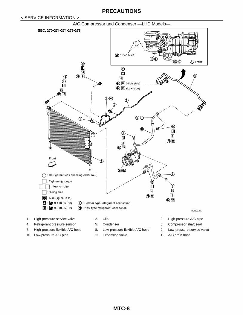
< SERVICE INFORMATION >A/C Compressor and Condenser —LHD Models—
MJIB0276E
1. High-pressure service valve 2. Clip 3. High-pressure A/C pipe
4. Refrigerant pressure sensor 5. Condenser 6. Compressor shaft seal
7. High-pressure flexible A/C hose 8. Low-pressure flexible A/C hose 9. Low-pressure service valve
10. Low-pressure A/C pipe 11. Expansion valve 12. A/C drain hose
MTC-8
PRECAUTIONS
C
D
E
F
G
H
I
K
L
M
A
B
TC
N
O
P
< SERVICE INFORMATION >
M
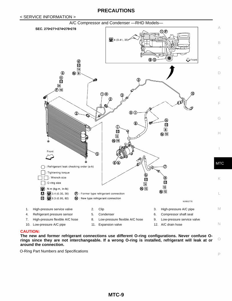
A/C Compressor and Condenser —RHD Models—
CAUTION:The new and former refrigerant connections use different O-ring configurations. Never confuse O-rings since they are not interchangeable. If a wrong O-ring is installed, refrigerant will leak at oraround the connection.
O-Ring Part Numbers and Specifications
MJIB0277E
1. High-pressure service valve 2. Clip 3. High-pressure A/C pipe
4. Refrigerant pressure sensor 5. Condenser 6. Compressor shaft seal
7. High-pressure flexible A/C hose 8. Low-pressure flexible A/C hose 9. Low-pressure service valve
10. Low-pressure A/C pipe 11. Expansion valve 12. A/C drain hose
MTC-9

PRECAUTIONS
< SERVICE INFORMATION >*: Always check with the Parts Department for the latest parts information.
WARNING:Make sure all refrigerant is discharged into the recycling equipment and the pressure in the system isless than atmospheric pressure. Then gradually loosen the discharge side hose fitting and remove it.CAUTION:When replacing or cleaning refrigerant cycle components, observe the following.• When the compressor is removed, store it in the same position as it is when mounted on the car.
Failure to do so will cause lubricant to enter the low pressure chamber.• When connecting tubes, always use a torque wrench and a back-up wrench.• After disconnecting tubes, immediately plug all openings to prevent entry of dirt and moisture.• When installing an air conditioner in the vehicle, connect the pipes as the final stage of the opera-
tion. Never remove the seal caps of pipes and other components until just before required for con-nection.
• Allow components stored in cool areas to warm to working area temperature before removing sealcaps. This prevents condensation from forming inside A/C components.
• Thoroughly remove moisture from the refrigeration system before charging the refrigerant.• Always replace used O-rings.• When connecting tube, apply lubricant to circle of the O-rings shown in illustration. Be careful not to
apply lubricant to threaded portion.Lubricant name: NISSAN A/C System Lubricant Type S (DH-PS) or equivalentPart number: KLH00-PAGS0
• O-ring must be closely attached to dented portion of tube.• When replacing the O-ring, be careful not to damage O-ring and tube.• Connect tube until you hear it click, then tighten the nut or bolt by hand until snug. Make sure that
the O-ring is installed to tube correctly.
Connec-tion type
O-ring size
Part number* D mm (in) W mm (in)
New 8 92471 N8210 6.8 (0.268) 1.85 (0.0728)
Former 10 J2476 89956 9.25 (0.3642) 1.78 (0.0701)
New12
92472 N8210 10.9 (0.429) 2.43 (0.0957)
Former 92475 71L00 11.0 (0.433) 2.4 (0.094)
New16
92473 N8210 13.6 (0.535) 2.43 (0.0957)
Former 92475 72L00 14.3 (0.563) 2.3 (0.091)
New19
92474 N8210 16.5 (0.650) 2.43 (0.0957)
Former 92477 N8200 17.12 (0.6740) 1.78 (0.0701)
New 24 92195 AH300 21.8 (0.858) 2.4 (0.094)
SHA814E
MTC-10

PRECAUTIONS
C
D
E
F
G
H
I
K
L
M
A
B
TC
N
O
P
< SERVICE INFORMATION >
M
• After connecting line, conduct leak test and make sure that there is no leakage from connections.When the gas leaking point is found, disconnect that line and replace the O-ring. Then tighten con-nections of seal seat to the specified torque.
Precaution for Service of Compressor INFOID:0000000006108162
• Plug all openings to prevent moisture and foreign matter from entering.• When the compressor is removed, store it in the same position as it is when mounted on the car.• When replacing or repairing compressor, follow “Maintenance of Lubricant Quantity in Compressor”
exactly. Refer to MTC-22, "Maintenance of Lubricant Quantity in Compressor".• Keep friction surfaces between clutch and pulley clean. If the surface is contaminated, with lubri-
cant, wipe it off by using a clean waste cloth moistened with thinner.• After compressor service operation, turn the compressor shaft by hand more than five turns in both
directions. This will equally distribute lubricant inside the compressor. After the compressor isinstalled, let the engine idle and operate the compressor for one hour.
• After replacing the compressor magnet clutch, apply voltage to the new one and check for usualoperation.
Precaution for Service Equipment INFOID:0000000006108163
RECOVERY/RECYCLING EQUIPMENTBe certain to follow the manufacturer’s instructions for machine operation and machine maintenance. Neverintroduce any refrigerant other than that specified into the machine.
ELECTRONIC LEAK DETECTORBe certain to follow the manufacturer’s instructions for tester operation and tester maintenance.
VACUUM PUMP
RHA861F
MTC-11
PRECAUTIONS
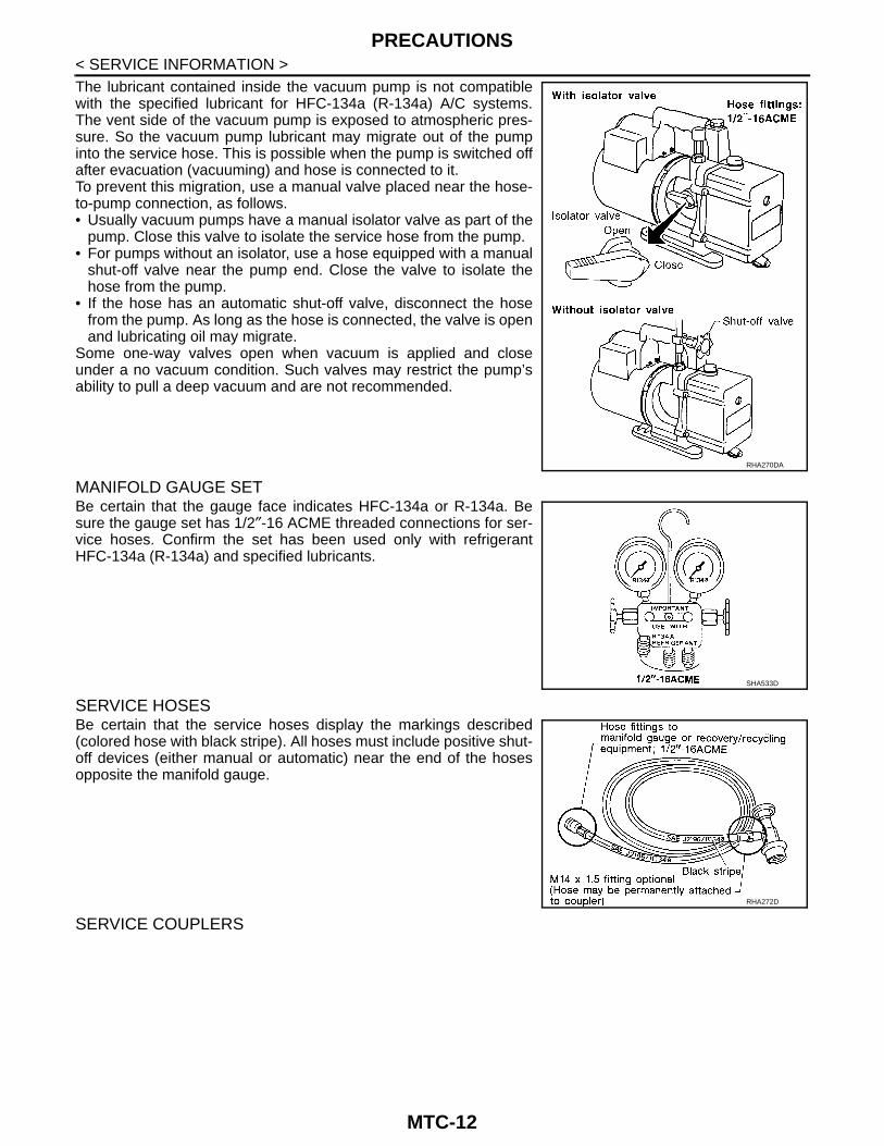
< SERVICE INFORMATION >The lubricant contained inside the vacuum pump is not compatiblewith the specified lubricant for HFC-134a (R-134a) A/C systems.The vent side of the vacuum pump is exposed to atmospheric pres-sure. So the vacuum pump lubricant may migrate out of the pumpinto the service hose. This is possible when the pump is switched offafter evacuation (vacuuming) and hose is connected to it.To prevent this migration, use a manual valve placed near the hose-to-pump connection, as follows.• Usually vacuum pumps have a manual isolator valve as part of thepump. Close this valve to isolate the service hose from the pump.• For pumps without an isolator, use a hose equipped with a manual
shut-off valve near the pump end. Close the valve to isolate thehose from the pump.
• If the hose has an automatic shut-off valve, disconnect the hosefrom the pump. As long as the hose is connected, the valve is openand lubricating oil may migrate.
Some one-way valves open when vacuum is applied and closeunder a no vacuum condition. Such valves may restrict the pump’sability to pull a deep vacuum and are not recommended.
MANIFOLD GAUGE SETBe certain that the gauge face indicates HFC-134a or R-134a. Besure the gauge set has 1/2″-16 ACME threaded connections for ser-vice hoses. Confirm the set has been used only with refrigerantHFC-134a (R-134a) and specified lubricants.
SERVICE HOSESBe certain that the service hoses display the markings described(colored hose with black stripe). All hoses must include positive shut-off devices (either manual or automatic) near the end of the hosesopposite the manifold gauge.
SERVICE COUPLERS
RHA270DA
SHA533D
RHA272D
MTC-12
PRECAUTIONS
C
D
E
F
G
H
I
K
L
M
A
B
TC
N
O
P
< SERVICE INFORMATION >
M
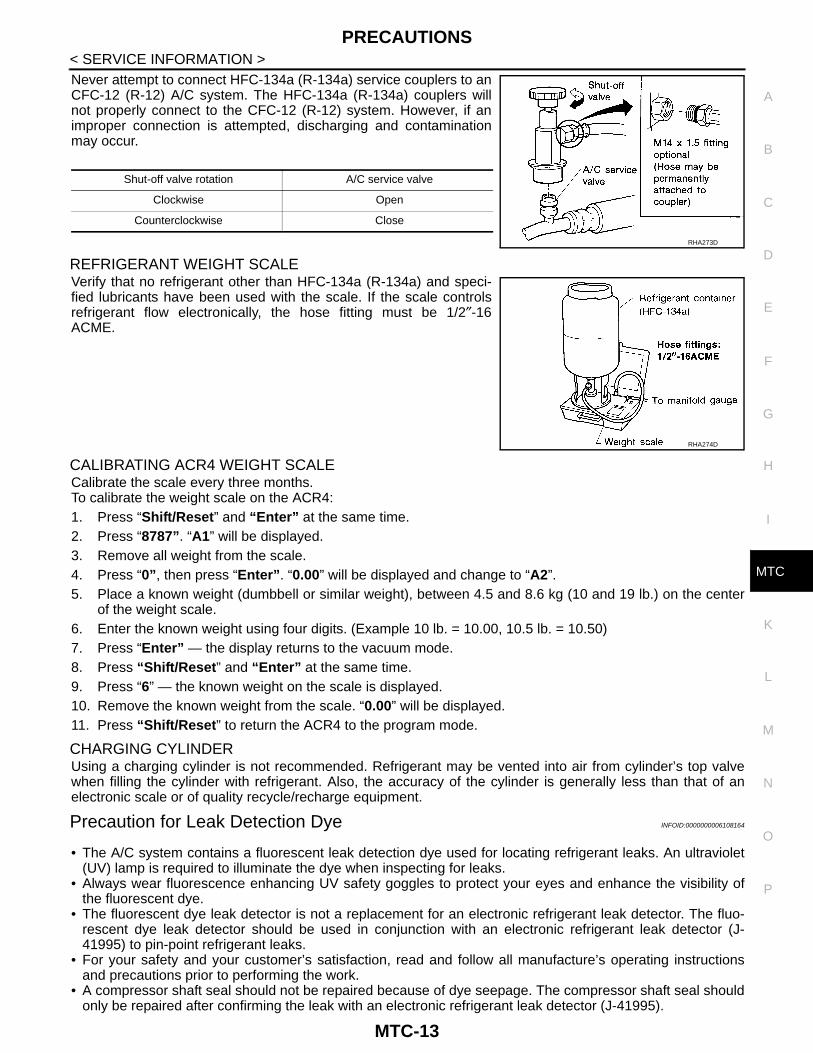
Never attempt to connect HFC-134a (R-134a) service couplers to anCFC-12 (R-12) A/C system. The HFC-134a (R-134a) couplers willnot properly connect to the CFC-12 (R-12) system. However, if animproper connection is attempted, discharging and contaminationmay occur.
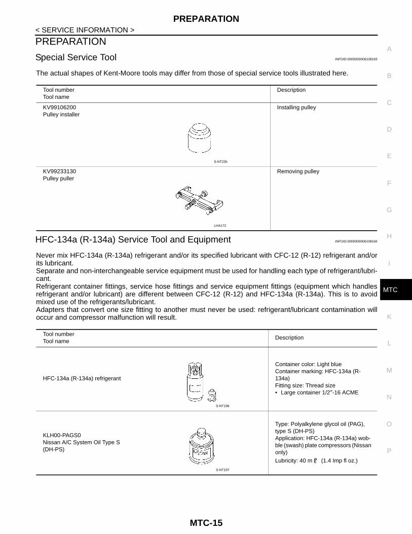
REFRIGERANT WEIGHT SCALEVerify that no refrigerant other than HFC-134a (R-134a) and speci-fied lubricants have been used with the scale. If the scale controlsrefrigerant flow electronically, the hose fitting must be 1/2″-16ACME.
CALIBRATING ACR4 WEIGHT SCALECalibrate the scale every three months.To calibrate the weight scale on the ACR4:1. Press “Shift/Reset” and “Enter” at the same time.2. Press “8787”. “A1” will be displayed.3. Remove all weight from the scale.4. Press “0”, then press “Enter”. “0.00” will be displayed and change to “A2”.5. Place a known weight (dumbbell or similar weight), between 4.5 and 8.6 kg (10 and 19 lb.) on the center
of the weight scale.6. Enter the known weight using four digits. (Example 10 lb. = 10.00, 10.5 lb. = 10.50)7. Press “Enter” — the display returns to the vacuum mode.8. Press “Shift/Reset” and “Enter” at the same time.9. Press “6” — the known weight on the scale is displayed.10. Remove the known weight from the scale. “0.00” will be displayed.11. Press “Shift/Reset” to return the ACR4 to the program mode.
CHARGING CYLINDERUsing a charging cylinder is not recommended. Refrigerant may be vented into air from cylinder’s top valvewhen filling the cylinder with refrigerant. Also, the accuracy of the cylinder is generally less than that of anelectronic scale or of quality recycle/recharge equipment.
Precaution for Leak Detection Dye INFOID:0000000006108164
• The A/C system contains a fluorescent leak detection dye used for locating refrigerant leaks. An ultraviolet(UV) lamp is required to illuminate the dye when inspecting for leaks.
• Always wear fluorescence enhancing UV safety goggles to protect your eyes and enhance the visibility ofthe fluorescent dye.
• The fluorescent dye leak detector is not a replacement for an electronic refrigerant leak detector. The fluo-rescent dye leak detector should be used in conjunction with an electronic refrigerant leak detector (J-41995) to pin-point refrigerant leaks.
• For your safety and your customer’s satisfaction, read and follow all manufacture’s operating instructionsand precautions prior to performing the work.
• A compressor shaft seal should not be repaired because of dye seepage. The compressor shaft seal shouldonly be repaired after confirming the leak with an electronic refrigerant leak detector (J-41995).
Shut-off valve rotation A/C service valve
Clockwise Open
Counterclockwise Close
RHA273D
RHA274D
MTC-13

PRECAUTIONS
< SERVICE INFORMATION >• Always remove any remaining dye from the leak area after repairs are complete to avoid a misdiagnosis dur-ing a future service.• Never allow dye to come into contact with painted body panels or interior components. If dye is spilled, clean
immediately with the approved dye cleaner. Fluorescent dye left on a surface for an extended period of timecannot be removed.
• Never spray the fluorescent dye cleaning agent on hot surfaces (engine exhaust manifold, etc.).• Never use more than one refrigerant dye bottle (1/4 ounce /7.4 cc) per A/C system.• Leak detection dyes for HFC-134a (R-134a) and CFC-12 (R-12) A/C systems are different. Never use HFC-
134a (R-134a) leak detection dye in CFC-12 (R-12) A/C system or CFC-12 (R-12) leak detector dye in HFC-134a (R-134a) A/C systems or A/C system damage may result.
• The fluorescent properties of the dye will remain for over three (3) years unless a compressor malfunctionoccurs.
IDENTIFICATIONNOTE:Vehicles with factory installed fluorescent dye have a green label.Vehicles without factory installed fluorescent dye have a blue label.
IDENTIFICATION LABEL FOR VEHICLEVehicles with factory installed fluorescent dye have this identificationlabel on the front side of hood.
SHA749F
MTC-14
PREPARATION
C
D
E
F
G
H
I
K
L
M
A
B
TC
N
O
P
< SERVICE INFORMATION >
M
PREPARATION
Special Service Tool INFOID:0000000006108165
The actual shapes of Kent-Moore tools may differ from those of special service tools illustrated here.
HFC-134a (R-134a) Service Tool and Equipment INFOID:0000000006108166
Never mix HFC-134a (R-134a) refrigerant and/or its specified lubricant with CFC-12 (R-12) refrigerant and/orits lubricant.Separate and non-interchangeable service equipment must be used for handling each type of refrigerant/lubri-cant.Refrigerant container fittings, service hose fittings and service equipment fittings (equipment which handlesrefrigerant and/or lubricant) are different between CFC-12 (R-12) and HFC-134a (R-134a). This is to avoidmixed use of the refrigerants/lubricant.Adapters that convert one size fitting to another must never be used: refrigerant/lubricant contamination willoccur and compressor malfunction will result.
Tool numberTool name
Description
KV99106200Pulley installer
Installing pulley
KV99233130Pulley puller
Removing pulley
S-NT235
LHA172
Tool numberTool name
Description
HFC-134a (R-134a) refrigerant
Container color: Light blueContainer marking: HFC-134a (R-134a)Fitting size: Thread size• Large container 1/2″-16 ACME
KLH00-PAGS0Nissan A/C System Oil Type S (DH-PS)
Type: Polyalkylene glycol oil (PAG), type S (DH-PS)Application: HFC-134a (R-134a) wob-ble (swash) plate compressors (Nissan only)
Lubricity: 40 m (1.4 Imp fl oz.)
S-NT196
S-NT197
MTC-15

PREPARATION
< SERVICE INFORMATION >Recovery/Recycling/Recharging equipment (ACR4)
Function: Refrigerant recovery and re-cycling and recharging
Electrical leak detectorPower supply:DC 12V (Cigarette lighter)
(J-43926)Refrigerant dye leak detection kitKit includes:(J-42220) UV lamp and UV safety goggles(J-41459)HFC-134a (R-134a) dye injectorUse with J-41447, 1/4 ounce bottle(J-41447)HFC-134a (R-134a) fluorescent leak detection dye(Box of 24, 1/4 ounce bottles)(J-43872)Refrigerant dye cleaner
Power supply:DC 12V (Battery terminal)
(J-42220) UV lamp and UV safety goggles
Power supply:DC 12V (Battery terminal)For checking refrigerant leak when flu-orescent dye is installed in A/C systemIncludes:UV lamp and UV safety goggles
(J-41447)HFC-134a (R-134a) fluorescent leak detection dye(Box of 24, 1/4 ounce bottles)
Application: For HFC-134a (R-134a) PAG oilContainer: 1/4 ounce (7.4 cc) bottle(Includes self-adhesive dye identifica-tion labels for affixing to vehicle after charging system with dye.)
Tool numberTool name
Description
RJIA0195E
SHA705EB
ZHA200H
SHA438F
SHA439F
MTC-16

PREPARATION
C
D
E
F
G
H
I
K
L
M
A
B
TC
N
O
P
< SERVICE INFORMATION >
M
(J-41459)HFC-134a (R-134a) dye injectorUse with J-41447, 1/4 ounce bottle
For injecting 1/4 ounce of fluorescent leak detection dye into A/C system.
(J-43872)Refrigerant dye cleaner
For cleaning dye spills.
Manifold gauge set (with hoses and couplers)
Identification:• The gauge face indicates HFC-134a
(R-134a).Fitting size: Thread size• 1/2″-16 ACME
Service hoses• High-pressure side hose• Low-pressure side hose• Utility hose
Hose color:• Low hose: Blue with black stripe• High hose: Red with black stripe• Utility hose: Yellow with black stripe
or green with black stripeHose fitting to gauge:• 1/2″-16 ACME
Service couplers• High-pressure side coupler• Low-pressure side coupler
Hose fitting to service hose:M14 x 1.5 fitting is optional or perma-nently attached.
Tool numberTool name
Description
SHA440F
SHA441F
RJIA0196E
S-NT201
S-NT202
MTC-17

PREPARATION
< SERVICE INFORMATION >Commercial Service Tool INFOID:0000000006108167
Refrigerant weight scaleFor measuring of refrigerantFitting size: Thread size1/2″-16 ACME
Vacuum pump(Including the isolator valve)
Capacity:• Air displacement: 4 CFM• Micron rating: 20 microns• Oil capacity: 482 g (17 oz.)
Fitting size: Thread size• 1/2″-16 ACME
Tool numberTool name
Description
S-NT200
S-NT203
Tool numberTool name
Description
(J-44614)Clutch disk holding tool
Clutch disk holding tool
WHA230
MTC-18

REFRIGERATION SYSTEM
C
D
E
F
G
H
I
K
L
M
A
B
TC
N
O
P
< SERVICE INFORMATION >
M
REFRIGERATION SYSTEM
Refrigerant Cycle INFOID:0000000006108168
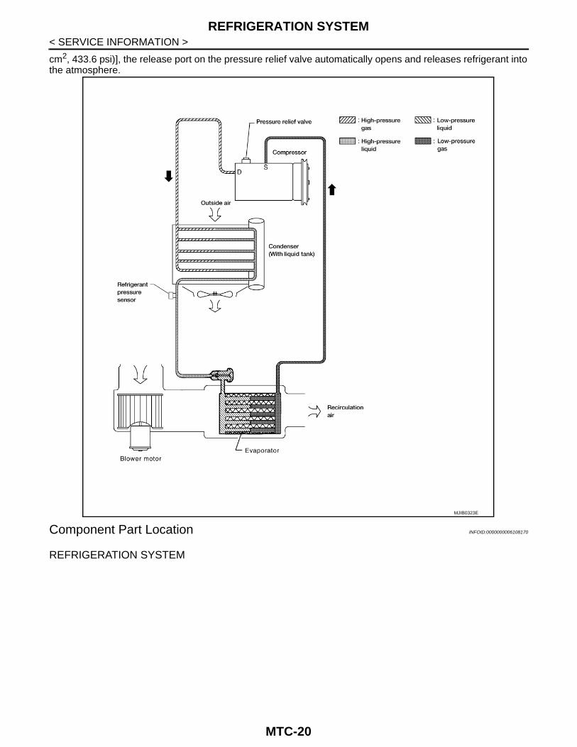
REFRIGERANT FLOWThe refrigerant flows in the standard pattern, that is, through the compressor, the condenser with liquid tank,through the evaporator, and back to the compressor. The refrigerant evaporation through the evaporator iscontrolled by an externally equalized expansion valve, located inside the evaporator case.
FREEZE PROTECTIONUnder usual operating conditions, when the A/C is switched ON, the compressor runs continuously, and theevaporator pressure, and therefore, temperature is controlled by the V-6 variable displacement compressor toprevent freeze up.
Refrigerant System Protection INFOID:0000000006108169
REFRIGERANT PRESSURE SENSORThe refrigerant system is protected against excessively high or low pressures by the refrigerant pressure sen-sor, located on the condenser. If the system pressure rises above or falls below the specifications, the refriger-ant pressure sensor detects the pressure inside the refrigerant line and sends a voltage signal to the ECM.The ECM de-energizes the A/C relay to disengage the magnetic compressor clutch when pressure on the highpressure side detected by refrigerant pressure sensor is over about 2,746 kPa (28 kg/cm2, 398 psi), or belowabout 120 kPa (1.22 kg/cm2, 17.4 psi).
PRESSURE RELIEF VALVEThe refrigerant system is also protected by a pressure relief valve, located in the rear head of the compressor.When the pressure of refrigerant in the system increases to an abnormal level [more than 2,990 kPa (30.5 kg/
MTC-19
REFRIGERATION SYSTEM
< SERVICE INFORMATION >cm2, 433.6 psi)], the release port on the pressure relief valve automatically opens and releases refrigerant intothe atmosphere.
Component Part Location INFOID:0000000006108170
REFRIGERATION SYSTEM
MJIB0323E
MTC-20

REFRIGERATION SYSTEM
C
D
E
F
G
H
I
K
L
M
A
B
TC
N
O
P
< SERVICE INFORMATION >
M
1. Defroster nozzle 2. LH side demister duct 3. LH ventilator duct
4. RH side demister duct 5. RH ventilator duct 6. Center ventilator duct
7. Heater and cooling unit assembly 8. Floor duct 9. Clips
10. Heat duct
MJIB0217E
MTC-21

LUBRICANT
< SERVICE INFORMATION >LUBRICANT
Maintenance of Lubricant Quantity in Compressor INFOID:0000000006108171
The lubricant in the compressor circulates through the system with the refrigerant. Add lubricant to compres-sor when replacing any component or after a large refrigerant leakage has occurred. It is important to maintainthe specified amount.If lubricant quantity is not maintained properly, the following malfunctions may result:• Lack of lubricant: May lead to a seized compressor• Excessive lubricant: Inadequate cooling (thermal exchange interference)
LUBRICANTName: NISSAN A/C System Lubricant Type S (DH-PS)Part number: KLH00-PAGS0
CHECKING AND ADJUSTINGCAUTION:If excessive lubricant leakage is noted, never perform the lubricant return operation.Start the engine and set the following conditions:
test condition• Engine speed: Idling to 1,200 rpm• A/C switch: On• Blower speed: Max. position• Temp. control: Optional [Set so that intake air temperature is 25° to 30° C (77° to 86°F).]• Intake position: Recirculation ( )• Perform lubricant return operation for about ten minutesAdjust the lubricant quantity according to the following table.
Lubricant Adjusting Procedure for Components Replacement Except CompressorAfter replacing any of the following major components, add the correct amount of lubricant to the system.Amount of lubricant to be added
• *1: If refrigerant leak is small, no addition of lubricant is needed.
Lubricant Adjustment Procedure for Compressor Replacement
1. Before connecting recovery/recycling equipment to vehicle, check recovery/recycling equipment gauges.No refrigerant pressure should be displayed. If NG, recover refrigerant from equipment lines.
2. Discharge refrigerant into the refrigerant recovery/recycling equipment. Measure lubricant discharged intothe recovery/recycling equipment.
3. Drain the lubricant from the “old” (removed) compressor into a graduated container and recover theamount of lubricant drained.
4. Drain the lubricant from the “new” compressor into a separate, clean container.5. Measure an amount of new lubricant installed equal to amount drained from “old” compressor. Add this
lubricant to “new” compressor through the suction port opening.6. Measure an amount of new lubricant equal to the amount recovered during discharging. Add this lubricant
to “new” compressor through the suction port opening.
Part replacedLubricant to be added to system
RemarksAmount of lubricantm (Imp fl oz)
Evaporator 75 (2.6) —
Condenser 75 (2.6) —
Liquid tank 5 (0.2)Add if compressor is not re-
placed.
In case of refrigerant leak30 (1.1) Large leak
— Small leak *1
MTC-22

LUBRICANT
C
D
E
F
G
H
I
K
L
M
A
B
TC
N
O
P
< SERVICE INFORMATION >
M
7. If the liquid tank also needs to be replaced, add an additional 5 m (0.2 Imp fl oz) of lubricant at this time.Never add this 5 m (0.2 Imp fl oz) of lubricant if only replacing the compressor.
RHA065DI
MTC-23
AIR CONDITIONER CONTROL
< SERVICE INFORMATION >AIR CONDITIONER CONTROL
Description INFOID:0000000006108172
The front air control provides regulation of the vehicle's interior temperature. The system is based on the posi-tion of the front air controls temperature switch selected by the driver. This is done by utilizing a microcom-puter, also referred to as the front air control, which receives input signals from the following three sensors:• Intake sensor• PBR (Position Balanced Resistor).The front air control uses these signals (including the set position of the temperature switch) to control:• Outlet air volume• Air temperature• Air distribution
The front air control is used to select: • Outlet air volume• Air temperature/distribution
Operation INFOID:0000000006108173
AIR MIX DOOR CONTROLThe air mix door is controlled so that in-vehicle temperature changed based on the position of the temperatureswitch.
BLOWER SPEED CONTROLBlower speed is controlled based on front blower switch settings.When blower switch is turned, the blower motor starts and increases air flow volume each time the blowerswitch is turned clockwise, and decreases air flow volume each time the blower switch is turned counterclock-wise.When engine coolant temperature is low, the blower motor operation is delayed to prevent cool air from flow-ing.
INTAKE DOORS CONTROLThe intake doors are controlled by the recirculation switch setting, and the mode (defroster) switch setting.
MODE DOOR CONTROLThe mode door is controlled by the position of the mode switch.
DEFROSTER DOOR CONTROLThe defroster door is controlled by: Turning the defroster dial to front defroster.
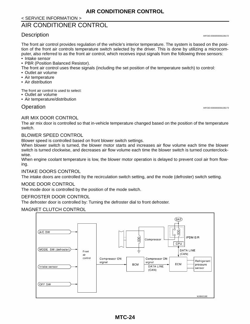
MAGNET CLUTCH CONTROL
MJIB0218E
MTC-24

AIR CONDITIONER CONTROL
C
D
E
F
G
H
I
K
L
M
A
B
TC
N
O
P
< SERVICE INFORMATION >
M
When the A/C switch is pressed, or the mode switch is turned to the defroster position, the front air control out-puts a compressor ON signal to BCM.The BCM then sends a compressor ON signal to ECM, via CAN communication line.ECM judges whether compressor can be turned ON, based on each sensor status (refrigerant pressure sen-sor signal, throttle angle sensor, etc.). If it judges compressor can be turned ON, it sends compressor ON sig-nal to IPDM E/R, via CAN communication line.Upon receipt of compressor ON signal from ECM, IPDM E/R turns air conditioner relay ON to operate com-pressor.
SELF-DIAGNOSTIC SYSTEMThe self-diagnostic system is built into the front air control to quickly locate the cause of symptoms. Refer toMTC-37, "A/C System Self-Diagnosis Function".
Description of Control System INFOID:0000000006108174
The control system consists of input sensors, switches, the front air control (microcomputer) and outputs.The relationship of these components is shown in the figure below:
MJIB0219E
MTC-25

AIR CONDITIONER CONTROL
< SERVICE INFORMATION >Control Operation INFOID:0000000006108175
Front air control
DISPLAY SCREENDisplays the operational status of the system.
TEMPERATURE SWITCH (TEMPERATURE CONTROL) (FRONT)Increases or decreases the set temperature.
RECIRCULATION ( ) SWITCH• When REC switch is ON, REC switch indicator goes ON, and air inlet is set to REC.• When REC switch is OFF, or when compressor is turned from ON to OFF, REC switch is automatically
turned OFF. REC mode can be re-entered by pressing REC switch again.• REC switch is not operated when DEF switch is ON, or at the D/F position.
REAR WINDOW DEFOGGER SWITCHWhen switch is ON, rear window is defogged.
OFF SWITCH (Blower speed set to 0)The compressor and blower are OFF, the intake doors are set to the outside air position, and the air outletdoors are set to the foot (75% foot and 25% defrost) position.
A/C SWITCHThe compressor is ON or OFF.
MODE SWITCHControls the air discharge outlets through control of the mode and defroster doors.
Discharge Air Flow INFOID:0000000006108176
FRONT
MJIB0222E
WJIA0540E
MTC-26

AIR CONDITIONER CONTROL
C
D
E
F
G
H
I
K
L
M
A
B
TC
N
O
P
< SERVICE INFORMATION >
M
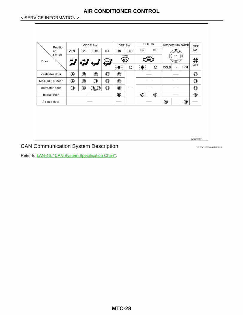
System Description INFOID:0000000006108177
SWITCHES AND THEIR CONTROL FUNCTION
MJIB0284E
MJIB0220E
MTC-27
AIR CONDITIONER CONTROL
< SERVICE INFORMATION >CAN Communication System Description INFOID:0000000006108178
Refer to LAN-46, "CAN System Specification Chart".
WJIA0532E
MTC-28

TROUBLE DIAGNOSIS
C
D
E
F
G
H
I
K
L
M
A
B
TC
N
O
P
< SERVICE INFORMATION >
M
TROUBLE DIAGNOSIS
CONSULT Function (BCM) INFOID:0000000006108179
CONSULT can display each diagnostic item using the diagnostic test modes shown following.
DATA MONITOR
How to Perform Trouble Diagnosis for Quick and Accurate Repair INFOID:0000000006108180
WORK FLOW
SYMPTOM TABLE
*1: Self-diagnosis not available on vehicles not equipped with navigation system display screen.
System part Check item, diagnosis mode Description
BCM Data monitor Displays BCM input data in real time.
Monitor item name “operation or unit”
Contents
IGN ON SW “ON/OFF” Displays “IGN Position (ON)/OFF, ACC Position (OFF)” status as judged from ignition switch signal.
COMP ON SIG “ON/OFF” Displays “COMP (ON)/COMP (OFF)” status as judged from air conditioner switch signal.
FAN ON SIG “ON/OFF” Displays “FAN (ON)/FAN (OFF)” status as judged from blower motor switch signal.
*1 MTC-39, "Operational Check"
SHA900E
Symptom Reference Page
A/C system does not come on. Go to Trouble Diagnosis Procedure for A/C System. MTC-40
A/C system cannot be controlled. Go to Self-diagnosis Function. MTC-37
Air outlet does not change.Go to Trouble Diagnosis Procedure for Mode Door Motor. MTC-42
Mode door motor is malfunctioning.
Discharge air temperature does not change.Go to Trouble Diagnosis Procedure for Air Mix Door Motor. MTC-47
Air mix door motor is malfunctioning.
Intake door does not change.Go to Trouble Diagnosis Procedure for Intake Door Motor. MTC-52
Intake door motor is malfunctioning.
Blower motor operation is malfunctioning. Go to Trouble Diagnosis Procedure for Blower Motor. MTC-55
Magnet clutch does not engage. Go to Trouble Diagnosis Procedure for Magnet Clutch. MTC-63
Insufficient cooling Go to Trouble Diagnosis Procedure for Insufficient Cooling. MTC-68
Insufficient heating Go to Trouble Diagnosis Procedure for Insufficient Heating. MTC-75
Noise Go to Trouble Diagnosis Procedure for Noise. MTC-76
Self-diagnosis cannot be performed *1. Go to Trouble Diagnosis Procedure for Self-diagnosis. MTC-78
MTC-29

TROUBLE DIAGNOSIS
< SERVICE INFORMATION >Component Parts and Harness Connector Location INFOID:0000000006108181
ENGINE COMPARTMENT
MJIB0318E
MTC-30

TROUBLE DIAGNOSIS
C
D
E
F
G
H
I
K
L
M
A
B
TC
N
O
P
< SERVICE INFORMATION >
M
FRONT PASSENGER COMPARTMENT
AWIIA0724ZZ
⇒ :Front 1. Front air control 2. Intake sensor
3. Intake door motor 4. Front blower motor resistor 5. Mode door motor
6. Air mix door motor
MTC-31

TROUBLE DIAGNOSIS
< SERVICE INFORMATION >Schematic - A/C - INFOID:0000000006108182
JMJWA0138GB
MTC-32
TROUBLE DIAGNOSIS
C
D
E
F
G
H
I
K
L
M
A
B
TC
N
O
P
< SERVICE INFORMATION >
M
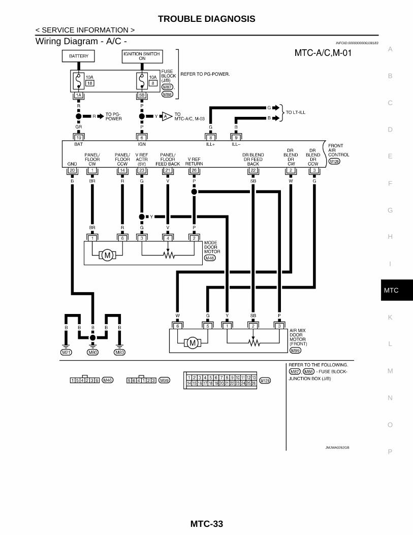
Wiring Diagram - A/C - INFOID:0000000006108183
JMJWA0262GB
MTC-33
TROUBLE DIAGNOSIS
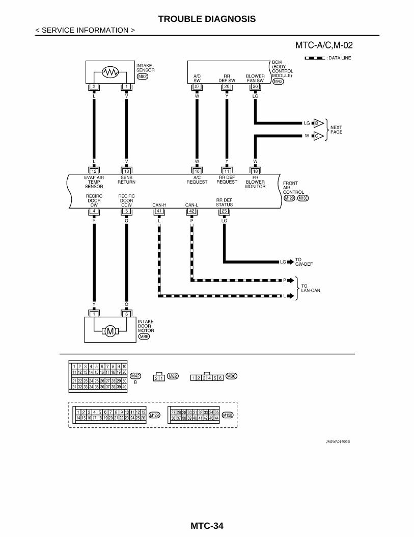
< SERVICE INFORMATION >JMJWA0140GB
MTC-34
TROUBLE DIAGNOSIS
C
D
E
F
G
H
I
K
L
M
A
B
TC
N
O
P
< SERVICE INFORMATION >
M
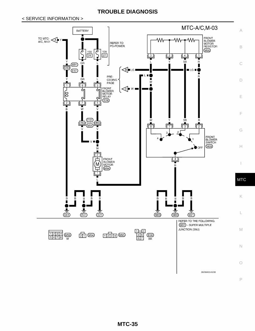
JMJWA0141GB
MTC-35
TROUBLE DIAGNOSIS
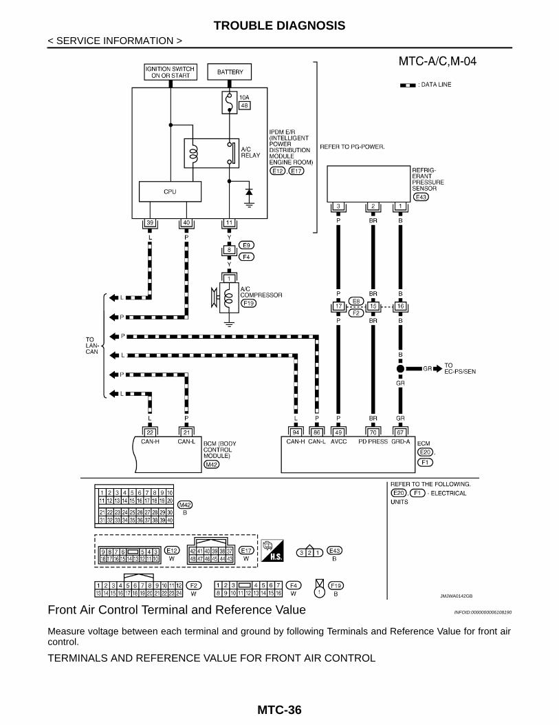
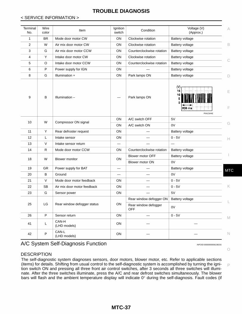
< SERVICE INFORMATION >Front Air Control Terminal and Reference Value INFOID:0000000006108190
Measure voltage between each terminal and ground by following Terminals and Reference Value for front aircontrol.
TERMINALS AND REFERENCE VALUE FOR FRONT AIR CONTROL
JMJWA0142GB
MTC-36
TROUBLE DIAGNOSIS
C
D
E
F
G
H
I
K
L
M
A
B
TC
N
O
P
< SERVICE INFORMATION >
M
A/C System Self-Diagnosis Function INFOID:0000000006108191
DESCRIPTIONThe self-diagnostic system diagnoses sensors, door motors, blower motor, etc. Refer to applicable sections(items) for details. Shifting from usual control to the self-diagnostic system is accomplished by turning the igni-tion switch ON and pressing all three front air control switches, after 3 seconds all three switches will illumi-nate. After the three switches illuminate, press the A/C and rear defrost switches simultaneously. The blowerbars will flash and the ambient temperature display will indicate 0° during the self-diagnosis. Fault codes (if
Terminal No.
Wire color
ItemIgnition switch
ConditionVoltage (V)(Approx.)
1 BR Mode door motor CW ON Clockwise rotation Battery voltage
2 W Air mix door motor CW ON Clockwise rotation Battery voltage
3 G Air mix door motor CCW ON Counterclockwise rotation Battery voltage
4 Y Intake door motor CW ON Clockwise rotation Battery voltage
5 O Intake door motor CCW ON Counterclockwise rotation Battery voltage
6 P Power supply for IGN ON — Battery voltage
8 G Illumination + ON Park lamps ON Battery voltage
9 B Illumination – — Park lamps ON
10 W Compressor ON signalON A/C switch OFF 5V
ON A/C switch ON 0V
11 Y Rear defroster request ON — Battery voltage
12 L Intake sensor ON — 0 - 5V
13 V Intake sensor return — — —
14 R Mode door motor CCW ON Counterclockwise rotation Battery voltage
18 W Blower monitor ONBlower motor OFF Battery voltage
Blower motor ON 0V
19 GR Power supply for BAT — — Battery voltage
20 B Ground — — 0V
21 V Mode door motor feedback ON — 0 - 5V
22 SB Air mix door motor feedback ON — 0 - 5V
23 G Sensor power ON — 5V
25 LG Rear window defogger status ON
Rear window defogger ON Battery voltage
Rear window defogger OFF
0V
26 P Sensor return ON — 0 - 5V
41 LCAN-H(LHD models)
ON — —
42 PCAN-L(LHD models)
ON — —
PIIA2344E
MTC-37
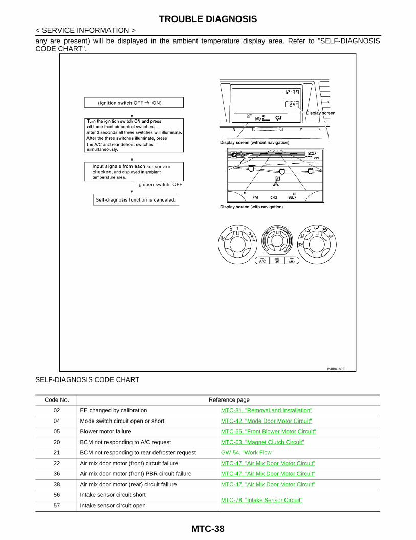
TROUBLE DIAGNOSIS
< SERVICE INFORMATION >any are present) will be displayed in the ambient temperature display area. Refer to "SELF-DIAGNOSISCODE CHART".SELF-DIAGNOSIS CODE CHART
MJIB0189E
Code No. Reference page
02 EE changed by calibration MTC-81, "Removal and Installation"
04 Mode switch circuit open or short MTC-42, "Mode Door Motor Circuit"
05 Blower motor failure MTC-55, "Front Blower Motor Circuit"
20 BCM not responding to A/C request MTC-63, "Magnet Clutch Circuit"
21 BCM not responding to rear defroster request GW-54, "Work Flow"
22 Air mix door motor (front) circuit failure MTC-47, "Air Mix Door Motor Circuit"
36 Air mix door motor (front) PBR circuit failure MTC-47, "Air Mix Door Motor Circuit"
38 Air mix door motor (rear) circuit failure MTC-47, "Air Mix Door Motor Circuit"
56 Intake sensor circuit shortMTC-78, "Intake Sensor Circuit"
57 Intake sensor circuit open
MTC-38

TROUBLE DIAGNOSIS
C
D
E
F
G
H
I
K
L
M
A
B
TC
N
O
P
< SERVICE INFORMATION >
M
Operational Check INFOID:0000000006108192
The purpose of the operational check is to confirm that the system operates properly.
CHECKING BLOWER1. Turn blower control switch clockwise. Blower should operate on
low speed. The blower symbol should have one blade lit (on dis-play).
2. Turn the blower control switch again, and continue checkingblower speed and blower symbol until all speeds are checked.
3. Leave blower on MAX speed. If NG, go to trouble diagnosis procedure for MTC-55, "Front BlowerMotor Circuit".If OK, continue with next check.
CHECKING DISCHARGE AIR1. Turn the mode switch.2. Each position indicator should change shape (on display, if
equipped).
3. Confirm that discharge air comes out according to the air distri-bution table.
Mode door position is checked in the next step.If NG, go to trouble diagnosis procedure for MTC-42, "Mode DoorMotor Circuit".If OK, continue with next check.NOTE:Confirm that the compressor clutch is engaged (sound or visualinspection) and intake door position is at fresh when the DEF or D/Fis selected.
CHECKING RECIRCULATION
80 CAN bus faultLAN-46, "CAN System Specification Chart"
81 BCM CAN message missing
82 Intake door motor circuit failure MTC-52, "Intake Door Motor Circuit"
92 Mode door motor circuit failure MTC-42, "Mode Door Motor Circuit"
Code No. Reference page
Conditions : Engine running and at normal operating temperature
MJIB0223E
MJIB0224E
MJIB0284E
MTC-39

TROUBLE DIAGNOSIS
< SERVICE INFORMATION >1. Press recirculation ( ) switch one time. Recirculation indica-tor should illuminate.
2. Press recirculation ( ) switch one more time. Recirculationindicator should go off.
3. Listen for intake door position change (blower sound shouldchange slightly).
If NG, go to trouble diagnosis procedure for MTC-52, "Intake DoorMotor Circuit".If OK, continue with next check.NOTE:Confirm that the compressor clutch is engaged (sound or visualinspection) and intake door position is at fresh when the DEF or D/F is selected.
CHECKING TEMPERATURE DECREASE1. Rotate temperature dial counterclockwise.2. Check for cold air at appropriate discharge air outlets.If NG, listen for sound of air mix door motor operation. If OK, go totrouble diagnosis procedure for MTC-68, "Insufficient Cooling". If airmix door motor appears to be malfunctioning, go to MTC-47, "Air MixDoor Motor Circuit".If OK, continue with next check.
CHECKING TEMPERATURE INCREASE1. Rotate temperature dial clockwise.2. Check for hot air at appropriate discharge air outlets.If NG, listen for sound of air mix door motor operation. If OK, go totrouble diagnosis procedure for MTC-75, "Insufficient Heating". If airmix door motor appears to be malfunctioning, go to MTC-47, "Air MixDoor Motor Circuit".If OK, continue with next check.
CHECK A/C SWITCH1. Press A/C switch with the blower switch ON.2. A/C switch indicator will go ON.
• Confirm that the compressor clutch engages (sound or visualinspection).
If NG, go to trouble diagnosis procedure for MTC-63, "Magnet ClutchCircuit".If OK, continue with next check.
Power Supply and Ground Circuit for Front Air Control INFOID:0000000006108193
SYMPTOM: A/C system does not come on.
INSPECTION FLOW
MJIB0225E
MJIB0226E
MJIB0227E
MJIB0228E
MTC-40

TROUBLE DIAGNOSIS
C
D
E
F
G
H
I
K
L
M
A
B
TC
N
O
P
< SERVICE INFORMATION >
M
COMPONENT DESCRIPTION
Front Air ControlThe front air control has a built-in microcomputer which processes information sent from various sensorsneeded for air conditioner operation. The air mix door motors, mode door motor, intake door motors, defrosterdoor motor, front blower motor and A/C compressor are then controlled.The front air control is unitized with control mechanisms. When the various switches and temperature dials areoperated, data is input to the front air control. Self-diagnostic functions are also built into the front air control to provide quick check of malfunctions (NAVIequipped vehicles only).
Potentio Temperature Control (PTC)The PTC is built into the front air control. It can be set from cold tohot or any intermediate position by rotating the temperature dial.
DIAGNOSTIC PROCEDURE FOR A/C SYSTEM
1.CHECK POWER SUPPLY CIRCUITS FOR FRONT AIR CONTROL
1. Turn ignition switch OFF.
*1 "Power Supply and Ground Circuit for Front Air Control".
*2 MTC-39, "Operational Check"
MJIB0229E
MJIB0230E
MTC-41

TROUBLE DIAGNOSIS
< SERVICE INFORMATION >2. Disconnect front air control connector.3. Check voltage between front air control harness connectorM129 terminals 6 and 19, and ground.
OK or NGOK >> GO TO 2.NG >> Check 10A fuses [Nos. 8 and 18, located in the fuse block (J/B)]. Refer to PG-89, "Terminal
Arrangement".• If fuses are OK, check harness for open circuit. Repair or replace as necessary.• If fuses are NG, replace fuse and check harness for short circuit. Repair or replace as neces-
sary.
2.CHECK GROUND CIRCUIT FOR FRONT AIR CONTROL
1. Turn ignition switch OFF.2. Check continuity between front air control harness connector
M129 terminal 20 and ground.
OK or NGOK >> Replace front air control. Refer to MTC-81, "Removal
and Installation".NG >> Repair or replace harness or connector.
Mode Door Motor Circuit INFOID:0000000006108194
SYMPTOM:• Air outlet does not change.• Mode door motor does not operate normally.
INSPECTION FLOW
Terminals Ignition switch position
(+)
(-) OFF ACC ONFront air control
connectorTerminal No.
M129 6
Ground
Approx. 0V Approx. 0VBattery voltage
M129 19Battery voltage
Battery voltage
Battery voltage
WJIA1082E
20 - Ground : Continuity should exist.
WJIA1239E
MTC-42
TROUBLE DIAGNOSIS
C
D
E
F
G
H
I
K
L
M
A
B
TC
N
O
P
< SERVICE INFORMATION >
M
SYSTEM DESCRIPTION
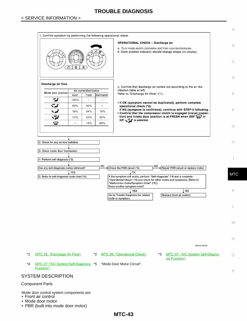
Component Parts
Mode door control system components are:• Front air control• Mode door motor• PBR (built into mode door motor)
*1 MTC-26, "Discharge Air Flow". *2 MTC-39, "Operational Check". *3 MTC-37, "A/C System Self-Diagno-sis Function".
*4 MTC-37, "A/C System Self-Diagnosis Function".
*5 "Mode Door Motor Circuit".
JMIIA0100GB
MTC-43

TROUBLE DIAGNOSIS
< SERVICE INFORMATION >System OperationThe mode door position (vent, B/L, foot, and defrost) is set by the front air control by means of the mode doormotor. When a mode door position is selected on the front air control, voltage is applied to one circuit of themode door motor while ground is applied to the other circuit, causing the mode door motor to rotate. The direc-tion of rotation is determined by which circuit has voltage applied to it, and which one has ground applied to it.The front air control monitors the mode door position by measuring the voltage signal on the PBR circuit.Mode Door Control Specification
COMPONENT DESCRIPTION
Mode Door MotorThe mode door motor is attached to the heater & cooling unit. Itrotates so that air is discharged from the outlet as indicated by thefront air control. Motor rotation is conveyed to a link which activatesthe mode door.NOTE:This illustration is for LHD models.The layout for RHD models is symmetrically opposite.
DIAGNOSTIC PROCEDURE FOR MODE DOOR MOTOR
1.CHECK RESULT FROM FRONT AIR CONTROL SELF-DIAGNOSIS OR PROCEED FROM SYMPTOM TA-BLE
Is vehicle equipped with NAVI?YES or NOYES >> GO TO 2.NO >> GO TO 5.
2.CHECK RESULT FROM FRONT AIR CONTROL SELF-DIAGNOSIS
Is self-diagnosis code 92 present? Refer toMTC-37, "A/C System Self-Diagnosis Function".YES or NOYES >> GO TO 3.NO >> GO TO 5.
3.CHECK MODE DOOR MOTOR VOLTAGE
WJIA0434E
MJIB0191E
MTC-44

TROUBLE DIAGNOSIS
C
D
E
F
G
H
I
K
L
M
A
B
TC
N
O
P
< SERVICE INFORMATION >
M
1. Turn ignition switch OFF.2. Disconnect mode door motor connector.3. Turn ignition switch ON.4. Check voltage between mode door motor harness connector
M46 terminals 1, 6 and ground.
OK or NGOK >> Replace mode door motor.NG >> GO TO 4.
4.CHECK POWER SUPPLY AND GROUND CIRCUITS FOR MODE DOOR MOTOR
1. Turn ignition switch OFF.2. Disconnect front air control connector.3. Check continuity between front air control harness connector
M129 terminal 1, 14 and mode door motor connector M46 termi-nal 1, 6.
4. Check continuity between front air control harness connectorM129 terminals 1, 14 and ground.
OK or NGOK >> Replace front air control.NG >> Repair or replace harness as necessary.
5.CHECK PBR REFERENCE SIGNAL VOLTAGE
Terminals
Condition Voltage(+)
(–)Mode door motor con-
nector
Terminal No.
M46
1
GroundMode switch
Turn clockwise
Battery voltage6
Turn counter-clockwise
JMIIA0010GB
1 - 1 : Continuity should exist.14 - 6 : Continuity should exist.
1 - Ground : Continuity should not exist.14 - Ground : Continuity should not exist.
JMIIA0011GB
MTC-45

TROUBLE DIAGNOSIS
< SERVICE INFORMATION >1. Reconnect front air control connector.2. Turn ignition switch ON.3. Check voltage between mode door motor harness connectorM46 terminal 3 and ground.
OK or NGOK >> GO TO 7.NG >> GO TO 6.
6.CHECK PBR REFERENCE VOLTAGE CIRCUIT BETWEEN MODE DOOR AND FRONT AIR CONTROL
1. Turn ignition switch OFF.2. Disconnect the front air control connector.3. Check continuity between mode door motor harness connector
M46 terminal 3 and front air control harness connector M129 ter-minal 23.
4. Check continuity between front air control harness connectorM129 terminal 23 and ground.
OK or NGOK >> Replace front air control. Refer to MTC-81, "Removal
and Installation".NG >> Repair or replace harness as necessary.
7.CHECK PBR GROUND REFERENCE CIRCUIT
3 - Ground : Approx. 5V
MJIB0233E
3 - 23 : Continuity should exist.
23 - Ground : Continuity should not exist.
JMIIA0012GB
MTC-46

TROUBLE DIAGNOSIS
C
D
E
F
G
H
I
K
L
M
A
B
TC
N
O
P
< SERVICE INFORMATION >
M
1. Turn ignition switch OFF.2. Disconnect the front air control connector.3. Check continuity between mode door motor harness connector
M46 terminal 2 and front air control harness connector M129 ter-minal 26.
4. Check continuity between front air control harness connectorM129 terminal 26 and ground.
OK or NGOK >> GO TO 8.NG >> Repair or replace harness as necessary.
8.CHECK PBR FEEDBACK SIGNAL
1. Reconnect the front air control connector and mode door motorconnector.
2. Turn ignition switch ON.3. Check voltage between front air control harness connector
M129 terminal 21 and ground.4. Press mode switch through all modes.
OK or NGOK >> Replace front air control. Refer to MTC-81, "Removal
and Installation".NG >> GO TO 9.
9.CHECK PBR FEEDBACK CIRCUIT
1. Turn ignition switch OFF.2. Disconnect the mode door motor connector and front air control
harness connector.3. Check continuity between mode door motor harness connector
M46 terminal 4 and front air control harness connector M129 ter-minal 21.
4. Check continuity between front air control harness connectorM129 terminal 21 and ground.
OK or NGOK >> Replace mode door motor. Refer to MTC-93, "Removal and Installation".NG >> Repair or replace harness as necessary.
Air Mix Door Motor Circuit INFOID:0000000006108195
SYMPTOM:
2 - 26 : Continuity should exist.
26 - Ground : Continuity should not exist.
JMIIA0013GB
21 - Ground : Approx. 0 - 5V
WJIA1088E
4 - 21 : Continuity should exist.
21 - Ground : Continuity should not exist.JMIIA0014GB
MTC-47

TROUBLE DIAGNOSIS
< SERVICE INFORMATION >• Discharge air temperature does not change.• Air mix door motor does not operate.INSPECTION FLOW
SYSTEM DESCRIPTION
Component Parts
Air mix door control system components are:• Front air control• Air mix door motor (front)• PBR (built-into air mix motor)
System Operation
*1 MTC-39, "Operational Check". *2 MTC-37, "A/C System Self-Diagno-sis Function".
*3 MTC-37, "A/C System Self-Diagno-sis Function".
*4 “DIAGNOSTIC PROCEDURE FOR AIR MIX DOOR MOTOR (FRONT)”.
*5 “DIAGNOSTIC PROCEDURE FOR AIR MIX DOOR MOTOR (FRONT)”.
MJIB0236E
MTC-48
TROUBLE DIAGNOSIS
C
D
E
F
G
H
I
K
L
M
A
B
TC
N
O
P
< SERVICE INFORMATION >
M
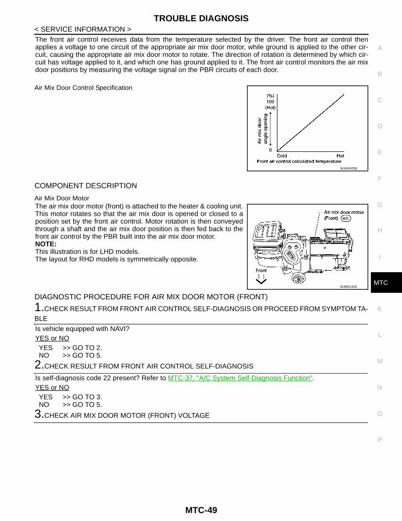
The front air control receives data from the temperature selected by the driver. The front air control thenapplies a voltage to one circuit of the appropriate air mix door motor, while ground is applied to the other cir-cuit, causing the appropriate air mix door motor to rotate. The direction of rotation is determined by which cir-cuit has voltage applied to it, and which one has ground applied to it. The front air control monitors the air mixdoor positions by measuring the voltage signal on the PBR circuits of each door.
Air Mix Door Control Specification
COMPONENT DESCRIPTION
Air Mix Door MotorThe air mix door motor (front) is attached to the heater & cooling unit.This motor rotates so that the air mix door is opened or closed to aposition set by the front air control. Motor rotation is then conveyedthrough a shaft and the air mix door position is then fed back to thefront air control by the PBR built into the air mix door motor.NOTE:This illustration is for LHD models.The layout for RHD models is symmetrically opposite.
DIAGNOSTIC PROCEDURE FOR AIR MIX DOOR MOTOR (FRONT)
1.CHECK RESULT FROM FRONT AIR CONTROL SELF-DIAGNOSIS OR PROCEED FROM SYMPTOM TA-BLE
Is vehicle equipped with NAVI?YES or NOYES >> GO TO 2.NO >> GO TO 5.
2.CHECK RESULT FROM FRONT AIR CONTROL SELF-DIAGNOSIS
Is self-diagnosis code 22 present? Refer to MTC-37, "A/C System Self-Diagnosis Function".YES or NOYES >> GO TO 3.NO >> GO TO 5.
3.CHECK AIR MIX DOOR MOTOR (FRONT) VOLTAGE
WJIA0435E
MJIB0192E
MTC-49

TROUBLE DIAGNOSIS
< SERVICE INFORMATION >1. Turn ignition switch OFF.2. Disconnect air mix door motor (front) connector.3. Turn ignition switch ON.4. Check voltage between air mix door motor (front) harness con-nector M99 terminals 5, 6 and ground.
OK or NGOK >> Replace air mix door motor (front).NG >> GO TO 4.
4.CHECK POWER SUPPLY CIRCUITS FOR AIR MIX DOOR MOTOR (FRONT)
1. Turn ignition switch OFF.2. Disconnect front air control connector.3. Check continuity between front air control harness connector
M129 terminal 2 and 3 and air mix door motor (front) connectorM99 terminal 6 and 5.
4. Check continuity between front air control harness connectorM129 terminals 2, 3 and ground.
OK or NGOK >> Replace front air control.NG >> Repair or replace harness as necessary.
5.CHECK PBR REFERENCE SIGNAL VOLTAGE
Terminals
Condition Voltage
(+)
(–)Air mix
door mo-tor (front) connector
Terminal No.
M995
GroundTem-pera-ture dial
Turn counter-clockwise Battery voltage
6 Turn clockwise
JMIIA0015GB
2 - 6 : Continuity should exist.3 - 5 : Continuity should exist.
2 - Ground : Continuity should not exist.3 - Ground : Continuity should not exist.
JMIIA0016GB
MTC-50

TROUBLE DIAGNOSIS
C
D
E
F
G
H
I
K
L
M
A
B
TC
N
O
P
< SERVICE INFORMATION >
M
1. Turn ignition switch OFF.2. Disconnect air mix door motor (front) connector.3. Turn ignition switch ON.4. Check voltage between air mix door motor (front) harness con-
nector M99 terminal 1 and ground.
OK or NGOK >> GO TO 7.NG >> GO TO 6.
6.CHECK PBR REFERENCE VOLTAGE CIRCUIT BETWEEN AIR MIX DOOR MOTOR (FRONT) ANDFRONT AIR CONTROL
1. Turn ignition switch OFF.2. Disconnect the front air control connector.3. Check continuity between air mix door motor (front) harness
connector M99 terminal 1 and front air control harness connec-tor M129 terminal 23.
4. Check continuity between front air control harness connectorM129 terminal 23 and ground.
OK or NGOK >> Replace front air control. Refer to MTC-81, "Removal
and Installation".NG >> Repair or replace harness as necessary.
7.CHECK PBR GROUND REFERENCE CIRCUIT
1 - Ground : Approx. 5V
MJIB0095E
1 - 23 : Continuity should exist.
23 - Ground : Continuity should not exist.
JMIIA0017GB
MTC-51
TROUBLE DIAGNOSIS
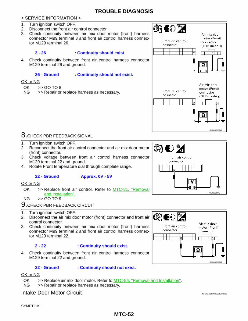
< SERVICE INFORMATION >1. Turn ignition switch OFF.2. Disconnect the front air control connector.3. Check continuity between air mix door motor (front) harnessconnector M99 terminal 3 and front air control harness connec-tor M129 terminal 26.
4. Check continuity between front air control harness connectorM129 terminal 26 and ground.
OK or NGOK >> GO TO 8.NG >> Repair or replace harness as necessary.
8.CHECK PBR FEEDBACK SIGNAL
1. Turn ignition switch OFF.2. Reconnect the front air control connector and air mix door motor
(front) connector.3. Check voltage between front air control harness connector
M129 terminal 22 and ground.4. Rotate Front temperature dial through complete range.
OK or NGOK >> Replace front air control. Refer to MTC-81, "Removal
and Installation".NG >> GO TO 9.
9.CHECK PBR FEEDBACK CIRCUIT
1. Turn ignition switch OFF.2. Disconnect the air mix door motor (front) connector and front air
control connector.3. Check continuity between air mix door motor (front) harness
connector M99 terminal 2 and front air control harness connec-tor M129 terminal 22.
4. Check continuity between front air control harness connectorM129 terminal 22 and ground.
OK or NGOK >> Replace air mix door motor. Refer to MTC-94, "Removal and Installation".NG >> Repair or replace harness as necessary.
Intake Door Motor Circuit INFOID:0000000006108196
SYMPTOM:
3 - 26 : Continuity should exist.
26 - Ground : Continuity should not exist.
JMIIA0018GB
22 - Ground : Approx. 0V - 5V
MJIB0098E
2 - 22 : Continuity should exist.
22 - Ground : Continuity should not exist.JMIIA0019GB
MTC-52

TROUBLE DIAGNOSIS
C
D
E
F
G
H
I
K
L
M
A
B
TC
N
O
P
< SERVICE INFORMATION >
M
• Intake door does not change.• Intake door motor does not operate normally.
INSPECTION FLOW
SYSTEM DESCRIPTION
Component Parts
Intake door control system components are:• Front air control• Intake door motor
System OperationThe intake door control determines the intake door position based on the position of the recirculation switch.When the recirculation switch is depressed the intake door motor rotate closing off the fresh air inlet and recir-culating the cabin air. If the recirculation switch is depressed again, the intake door motor rotate in the oppo-site direction, again allowing fresh air into the cabin.
*1 MTC-39, "Operational Check". *2 MTC-37, "A/C System Self-Diagno-sis Function".
*3 MTC-37, "A/C System Self-Diagno-sis Function".
MJIB0238E
MTC-53

TROUBLE DIAGNOSIS
< SERVICE INFORMATION >Intake Door Control SpecificationCOMPONENT DESCRIPTION
Intake door motorThe intake door motor is attached to the intake unit. It rotates so thatair is drawn from inlets set by the front air control. Motor rotation isconveyed to a lever which activates the intake door.NOTE:This illustration is for LHD models.The layout for RHD models is symmetrically opposite.
DIAGNOSTIC PROCEDURE FOR INTAKE DOOR MOTOR
1.CHECK RESULT FROM FRONT AIR CONTROL SELF-DIAGNOSIS
Is self-diagnosis code 82 present? Refer to MTC-37, "A/C System Self-Diagnosis Function".YES or NOYES >> GO TO 2.NO >> Replace front air control. Refer to MTC-81, "Removal and Installation".
2.CHECK INTAKE DOOR MOTOR VOLTAGE
1. Turn ignition switch OFF.2. Disconnect intake door motor connector.3. Turn ignition switch ON.4. Check voltage between intake door motor harness connector
M86 terminals 1, 6 and ground.
OK or NGOK >> Replace intake door motor. Refer to MTC-92, "Removal
and Installation".NG >> GO TO 3.
WJIA0436E
MJIB0194E
Terminals
Condition Voltage
(+)
(–)Intake
door mo-tor con-nector
Terminal No.
M86
1
GroundMode switch
Turn clockwise
Battery voltage6
Turn counter-clockwise
JMIIA0020GB
MTC-54
TROUBLE DIAGNOSIS
C
D
E
F
G
H
I
K
L
M
A
B
TC
N
O
P
< SERVICE INFORMATION >
M
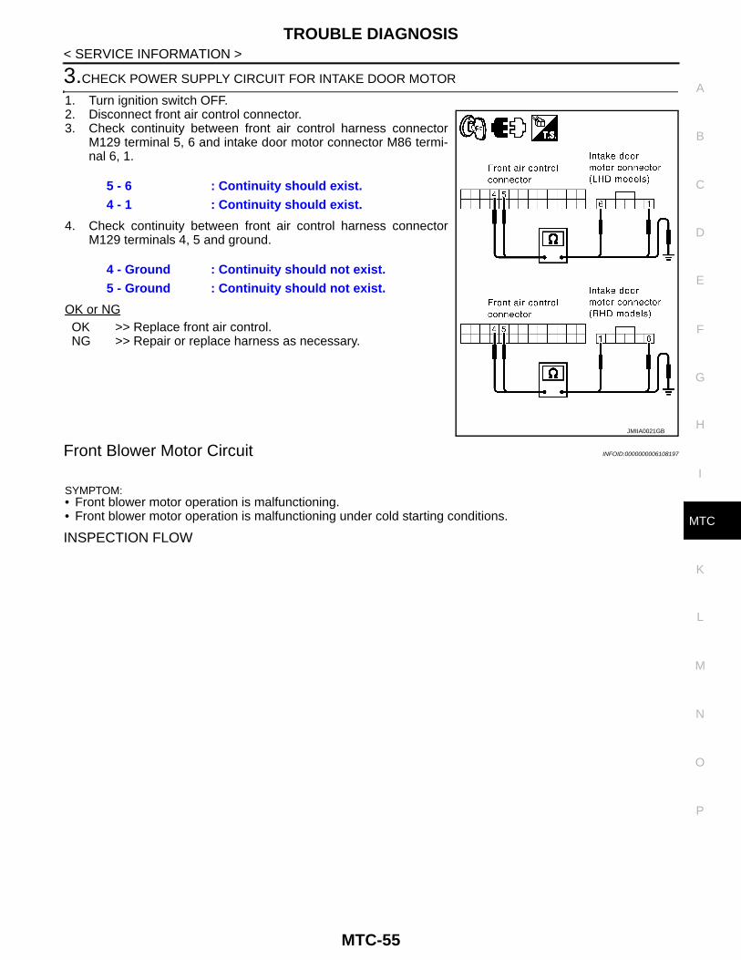
3.CHECK POWER SUPPLY CIRCUIT FOR INTAKE DOOR MOTOR
1. Turn ignition switch OFF.2. Disconnect front air control connector.3. Check continuity between front air control harness connector
M129 terminal 5, 6 and intake door motor connector M86 termi-nal 6, 1.
4. Check continuity between front air control harness connectorM129 terminals 4, 5 and ground.
OK or NGOK >> Replace front air control.NG >> Repair or replace harness as necessary.
Front Blower Motor Circuit INFOID:0000000006108197
SYMPTOM:• Front blower motor operation is malfunctioning.• Front blower motor operation is malfunctioning under cold starting conditions.
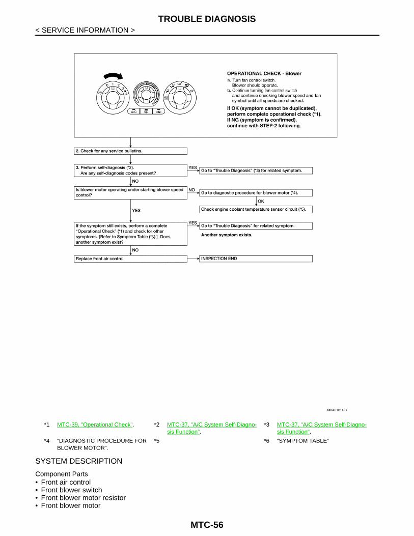
INSPECTION FLOW
5 - 6 : Continuity should exist.4 - 1 : Continuity should exist.
4 - Ground : Continuity should not exist.5 - Ground : Continuity should not exist.
JMIIA0021GB
MTC-55
TROUBLE DIAGNOSIS
< SERVICE INFORMATION >SYSTEM DESCRIPTION
Component Parts• Front air control• Front blower switch• Front blower motor resistor• Front blower motor
*1 MTC-39, "Operational Check". *2 MTC-37, "A/C System Self-Diagno-sis Function".
*3 MTC-37, "A/C System Self-Diagno-sis Function".
*4 “DIAGNOSTIC PROCEDURE FOR BLOWER MOTOR”.
*5 *6 “SYMPTOM TABLE”
JMIIA0101GB
MTC-56

TROUBLE DIAGNOSIS
C
D
E
F
G
H
I
K
L
M
A
B
TC
N
O
P
< SERVICE INFORMATION >
M
• Front blower motor relay
System Operation
Blower Speed Control Specification
COMPONENT DESCRIPTION
Front Blower Motor ResistorThe front blower motor resistor is located on the cooling unit. Thefront blower motor resistor grounds the front blower motor through aseries of 1, 2, or three resistors, depending upon speed selected.For high speed operation the front blower motor resistor is circum-vented and the front blower motor grounds directly.NOTE:This illustration is for LHD models.The layout for RHD models is symmetrically opposite.
DIAGNOSTIC PROCEDURE FOR BLOWER MOTOR
MJIB0324E
WJIA0441E
JMIIA0022GB
MTC-57
TROUBLE DIAGNOSIS
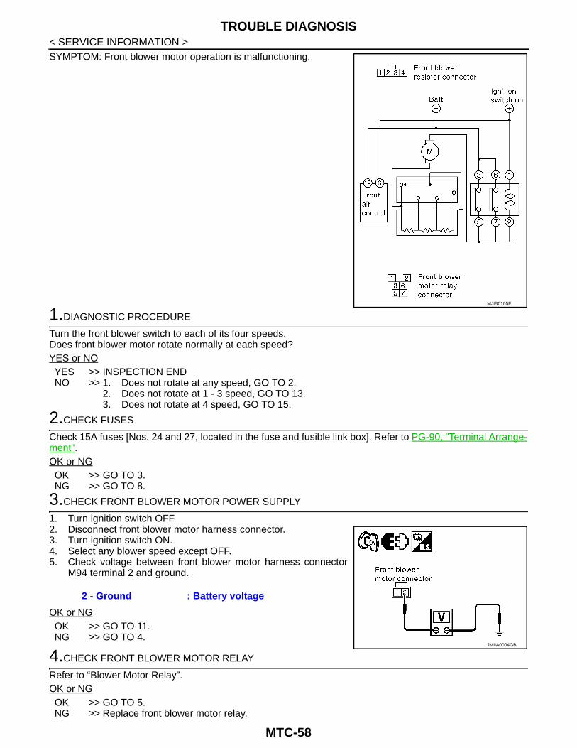
< SERVICE INFORMATION >SYMPTOM: Front blower motor operation is malfunctioning.1.DIAGNOSTIC PROCEDURE
Turn the front blower switch to each of its four speeds.Does front blower motor rotate normally at each speed?YES or NOYES >> INSPECTION ENDNO >> 1. Does not rotate at any speed, GO TO 2.
2. Does not rotate at 1 - 3 speed, GO TO 13.3. Does not rotate at 4 speed, GO TO 15.
2.CHECK FUSES
Check 15A fuses [Nos. 24 and 27, located in the fuse and fusible link box]. Refer to PG-90, "Terminal Arrange-ment".OK or NGOK >> GO TO 3.NG >> GO TO 8.
3.CHECK FRONT BLOWER MOTOR POWER SUPPLY
1. Turn ignition switch OFF.2. Disconnect front blower motor harness connector.3. Turn ignition switch ON.4. Select any blower speed except OFF.5. Check voltage between front blower motor harness connector
M94 terminal 2 and ground.
OK or NGOK >> GO TO 11.NG >> GO TO 4.
4.CHECK FRONT BLOWER MOTOR RELAY
Refer to “Blower Motor Relay”.OK or NGOK >> GO TO 5.NG >> Replace front blower motor relay.
MJIB0105E
2 - Ground : Battery voltage
JMIIA0004GB
MTC-58

TROUBLE DIAGNOSIS
C
D
E
F
G
H
I
K
L
M
A
B
TC
N
O
P
< SERVICE INFORMATION >
M
5.CHECK FRONT BLOWER MOTOR POWER FROM RELAY TO FRONT BLOWER MOTOR
1. Turn ignition switch OFF.2. Reconnect front blower motor harness connector.3. Disconnect front blower motor relay.4. Connect a jumper wire between front blower motor relay con-
nector E28 terminals 3 and 5 and between front blower motorrelay connector E28 terminals 6 and 7.
5. Turn ignition switch ON.6. Momentarily (no more than 4 seconds), set front blower switch
to any position except OFF.
OK or NGOK >> GO TO 6.NG >> GO TO 10.
6.CHECK FRONT BLOWER MOTOR RELAY (COIL SIDE) POWER SUPPLY CIRCUIT
1. Turn ignition switch ON.2. Check voltage between front blower motor relay harness con-
nector E28 terminal 1 and ground.
OK or NGOK >> GO TO 7.NG >> Repair or replace harness or connector.
7.CHECK FRONT BLOWER MOTOR RELAY (COIL SIDE) GROUND CIRCUIT
Check continuity between front blower motor relay harness connector E28 terminal 2 and ground.
OK or NGOK >> Replace front blower motor relay.NG >> Repair or replace harness or connector.
8.REPLACE FUSE
Refer to PG-89, "Terminal Arrangement".Does fuse open when front blower motor is turned on?YES or NOYES >> GO TO 9.NO >> INSPECTION END
9.CHECK FRONT BLOWER MOTOR POWER SUPPLY CIRCUIT FOR SHORT
1. Turn ignition switch OFF.
Front blower motor should rotate.
MJIB0106E
1 - Ground : Battery voltage.
WJIA0504E
2 - Ground : Continuity should exist.
WJIA0505E
MTC-59

TROUBLE DIAGNOSIS
< SERVICE INFORMATION >2. Disconnect front blower motor harness connector.3. Check continuity between front blower motor harness connectorM94 terminal 2 and ground.
OK or NGOK >> Check front blower motor. Refer to "Front Blower Motor".NG >> Repair or replace harness or connector.
10.CHECK FRONT BLOWER MOTOR RELAY (SWITCH SIDE) POWER SUPPLY CIRCUIT
1. Turn ignition switch OFF.2. Disconnect front blower motor harness connector.3. Check continuity between front blower motor relay harness con-
nector E28 terminal 5 and 7 and front blower motor harnessconnector M94 terminal 2.
4. Check continuity between front blower motor relay harness con-nector E28 terminals 5, 7 and ground.
OK or NGOK >> Repair harness or connector between front blower motor fuses and front blower motor relay.NG >> Repair harness or connector between front blower motor relay and front blower motor.
11.CHECK FRONT BLOWER MOTOR
Refer to "Front Blower Motor".OK or NGOK >> GO TO 12.NG >> Replace front blower motor.
12.CHECK FRONT BLOWER SWITCH
Refer to "Front Blower Switch".OK or NGOK >> Repair harness or connector between front blower switch and front blower motor.NG >> Replace front air control. Refer to MTC-81, "Removal and Installation".
13.CHECK FRONT BLOWER MOTOR RESISTOR
Refer to "Front Blower Motor Resistor".OK or NGOK >> GO TO 14.NG >> Replace front blower motor resistor. Refer to MTC-83, "Removal and Installation".
14.CHECK FRONT BLOWER MOTOR GROUND CIRCUIT TO FRONT BLOWER MOTOR RESISTOR
1. Turn ignition switch OFF.
2 - Ground : Continuity should not exist.
WJIA0649E
5, 7 - 2 : Continuity should exist.
5 - Ground : Continuity should not exist.7 - Ground : Continuity should not exist.
JMIIA0023GB
MTC-60

TROUBLE DIAGNOSIS
C
D
E
F
G
H
I
K
L
M
A
B
TC
N
O
P
< SERVICE INFORMATION >
M
2. Disconnect front blower motor and blower motor resistor har-ness connector.
3. Check continuity between front blower motor connector M94 ter-minal 1 and front blower motor resistor harness connector M95terminal 3.
4. Check continuity between front blower motor connector M94 ter-minal 1 and ground.
OK or NGOK >> Check condition of harness and connector.NG >> Repair or replace harness or connector.
15.CHECK FRONT BLOWER SWITCH
Refer to "Front Blower Switch".OK or NGOK >> GO TO 16.NG >> Replace front blower switch.
16.CHECK FRONT BLOWER MOTOR GROUND CIRCUIT TO FRONT BLOWER SWITCH
1. Turn ignition switch OFF.2. Disconnect front blower motor connector and front blower switch
connector.3. Check continuity between front blower motor harness connector
M94 terminal 1 and front blower switch harness connector M59terminal 8.
4. Check continuity between front blower motor harness connectorM94 terminal 1 and ground.
OK or NGOK >> Check front blower switch. If NG, replace front blower switch.NG >> Repair or replace harness or connector.
COMPONENT INSPECTION
Front Blower Motor Relay
1 - 3 : Continuity should exist.
1 - Ground : Continuity should not exist. WJIA0647E
1 - 8 : Continuity should exist.
1 - Ground : Continuity should not exist. JMIIA0102GB
MTC-61

TROUBLE DIAGNOSIS
< SERVICE INFORMATION >Check continuity between terminals by supplying 12 volts andground to coil side terminals of relay.Front Blower MotorConfirm smooth rotation of the front blower motor.• Ensure that there are no foreign particles inside the front blower unit.• Apply 12 volts to terminal + and ground to terminal - and verify that
the motor operates freely and quietly.
Front Blower SwitchCheck continuity between terminals at each switch position.
Front Blower Motor Resistor
LJIA0068E
JMIIA0025GB
WJIA0508E
MTC-62

TROUBLE DIAGNOSIS
C
D
E
F
G
H
I
K
L
M
A
B
TC
N
O
P
< SERVICE INFORMATION >
M
Check continuity between terminals. There will be resistance, butthere should not be an open or short between any two terminals.
Magnet Clutch Circuit INFOID:0000000006108198
SYMPTOM: Magnet clutch does not engage.
INSPECTION FLOW
SYSTEM DESCRIPTIONThe front air control controls compressor operation based on intake temperature and a signal from ECM.
Low Temperature Protection ControlThe front air control will turn the compressor ON or OFF as determined by a signal detected by the intake sen-sor.When intake air temperature is higher than the preset value, the compressor turns ON. The compressor turnsOFF when intake air temperature is lower than the preset value. That preset value is dependent on the ambi-ent temperature, refer to the following table.
MJIB0241E
*1 MTC-39, "Operational Check" *2 MTC-78, "Intake Sensor Circuit".
JMIIA0006GB
MTC-63
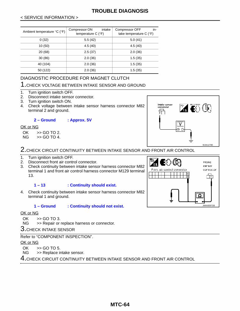
TROUBLE DIAGNOSIS
< SERVICE INFORMATION >DIAGNOSTIC PROCEDURE FOR MAGNET CLUTCH
1.CHECK VOLTAGE BETWEEN INTAKE SENSOR AND GROUND
1. Turn ignition switch OFF.2. Disconnect intake sensor connector.3. Turn ignition switch ON.4. Check voltage between intake sensor harness connector M82
terminal 2 and ground.
OK or NGOK >> GO TO 2.NG >> GO TO 4.
2.CHECK CIRCUIT CONTINUITY BETWEEN INTAKE SENSOR AND FRONT AIR CONTROL
1. Turn ignition switch OFF.2. Disconnect front air control connector.3. Check continuity between intake sensor harness connector M82
terminal 1 and front air control harness connector M129 terminal13.
4. Check continuity between intake sensor harness connector M82terminal 1 and ground.
OK or NGOK >> GO TO 3.NG >> Repair or replace harness or connector.
3.CHECK INTAKE SENSOR
Refer to “COMPONENT INSPECTION”.OK or NGOK >> GO TO 5.NG >> Replace intake sensor.
4.CHECK CIRCUIT CONTINUITY BETWEEN INTAKE SENSOR AND FRONT AIR CONTROL
Ambient temperature °C (°F)Compressor ON intake
temperature C (°F)Compressor OFF in-
take temperature C (°F)
0 (32) 5.5 (42) 5.0 (41)
10 (50) 4.5 (40) 4.5 (40)
20 (68) 2.5 (37) 2.0 (36)
30 (86) 2.0 (36) 1.5 (35)
40 (104) 2.0 (36) 1.5 (35)
50 (122) 2.0 (36) 1.5 (35)
2 – Ground : Approx. 5V
WJIA1278E
1 – 13 : Continuity should exist.
1 – Ground : Continuity should not exist. JMIIA0097GB
MTC-64

TROUBLE DIAGNOSIS
C
D
E
F
G
H
I
K
L
M
A
B
TC
N
O
P
< SERVICE INFORMATION >
M
1. Turn ignition switch OFF.2. Disconnect front air control connector.3. Check continuity between intake sensor harness connector M82
terminal 2 and front air control harness connector M129 terminal12.
4. Check continuity between intake sensor harness connector M82terminal 2 and ground.
OK or NGOK >> Replace front air control.NG >> Repair or replace harness or connector.
5.PERFORM AUTO ACTIVE TEST
Refer to PG-28, "Auto Active Test".Does magnet clutch operate?YES or NOYES >> • WITH CONSULT
GO TO 8.• WITHOUT CONSULT
GO TO 9.NO >> Check 10A fuse (No. 42, located in IPDM E/R), and GO TO 6.
6.CHECK CIRCUIT CONTINUITY BETWEEN IPDM E/R AND A/C COMPRESSOR
1. Turn ignition switch OFF.2. Disconnect IPDM E/R connector and A/C compressor (magnet
clutch) connector.3. Check continuity between IPDM E/R harness connector E12 ter-
minal 11 and A/C compressor harness connector F19 terminal 1.
4. Check continuity between IPDM E/R harness connector E12 ter-minal 11 and ground.
OK or NGOK >> GO TO 7.NG >> Repair or replace harness or connector.
7.CHECK MAGNET CLUTCH CIRCUIT
Check for operation sound when applying battery voltage direct cur-rent to terminal.OK or NGOK >> Replace IPDM E/R.NG >> Replace magnet clutch. Refer to MTC-105, "Removal
and Installation for Compressor Clutch".
8.CHECK BCM INPUT (COMPRESSOR ON) SIGNAL
Check compressor ON/OFF signal. Refer to MTC-29, "CONSULT Function (BCM)".
2 – 12 : Continuity should exist.
2 – Ground : Continuity should not exist. WJIA1158E
11 – 1 : Continuity should exist.
11 – Ground : Continuity should not exist. JMIIA0094GB
SJIA0197E
MTC-65

TROUBLE DIAGNOSIS
< SERVICE INFORMATION >OK or NGOK >> GO TO 11.NG >> GO TO 9.
9.CHECK CIRCUIT CONTINUITY BETWEEN BCM AND FRONT AIR CONTROL
1. Turn ignition switch OFF.2. Disconnect BCM connector and front air control connector.3. Check continuity between BCM harness connector M42 terminal
27 and front air control harness connector M129 terminal 10.
4. Check continuity between BCM harness connector M42 terminal27 and ground.
OK or NGOK >> GO TO 10.NG >> Repair or replace harness or connector.
10.CHECK VOLTAGE FOR FRONT AIR CONTROL (COMPRESSOR ON SIGNAL)
1. Reconnect BCM connector and front air control connector.2. Turn ignition switch ON.3. Check voltage between front air control harness connector
M129 terminal 10 and ground.
OK or NGOK >> GO TO 11.NG-1 >> If the voltage is approx. 5V when A/C switch is ON, replace front air control. Refer to MTC-81,
"Removal and Installation".NG-2 >> If the voltage is approx. 0V when A/C switch is OFF, replace BCM. Refer to BCS-13, "Removal
and Installation of BCM".
11.CHECK REFRIGERANT PRESSURE SENSOR
Check refrigerant pressure sensor. Refer to the following.• VQ (TYPE 1)*: Refer to EC-513, "Diagnosis Procedure".• VQ (TYPE 2)*: Refer to EC-896, "Diagnosis Procedure".• YD25DDTi: Refer to EC-1203, "Component Function Check".• V9X: Refer to EC-1421, "DTC Logic".*: Regarding to the vehicle type, refer to EC-23, "How to Check Vehicle Type".Is the inspection result normal?YES-1 >> WITH CONSULT: GO TO 12.YES-2 >> WITHOUT CONSULT: GO TO 13.NO >> Repair or replace malfunctioning parts.
12.CHECK BCM INPUT (FAN ON) SIGNAL
Check FAN ON/OFF signal. Refer to MTC-29, "CONSULT Function (BCM)".
A/C SW ON : COMP ON SIG ONA/C SW OFF : COMP ON SIG OFF
27 - 10 : Continuity should exist.
27 - Ground : Continuity should not exist.JMIIA0095GB
Terminals
Condition Voltage(+)
(–)Front air con-trol connec-
torTerminal No.
M129 10 GroundA/C switch: ON Approx. 0V
A/C switch: OFF Approx. 5V
WJIA1137E
MTC-66

TROUBLE DIAGNOSIS
C
D
E
F
G
H
I
K
L
M
A
B
TC
N
O
P
< SERVICE INFORMATION >
M
OK or NGOK >> GO TO 15.NG >> GO TO 13.
13.CHECK CIRCUIT CONTINUITY BETWEEN BCM, FRONT AIR CONTROL AND BLOWER SWITCH
1. Turn ignition switch OFF.2. Disconnect BCM connector and front air control connector and
blower switch.3. Check continuity between BCM harness connector M42 terminal
26 and blower switch M59 terminal 2 and between front air con-trol harness connector M129 terminal 18 and blower switch M59terminal 8.
4. Check continuity between BCM harness connector M42 terminal26 and ground, and between front air control harness connectorM129 terminal 18 and ground.
OK or NGOK >> GO TO 14.NG >> Repair or replace harness or connector.
14.CHECK VOLTAGE FOR BCM (FAN ON SIGNAL) AND FRONT AIR CONTROL (BLOWER MONITORSIGNAL)
1. Reconnect BCM connector and front air control connector andblower switch.
2. Turn ignition switch ON.3. Check voltage between the following terminals.
OK or NGOK >> GO TO 15.NG-1 >> If the voltage is approx.12V when blower motor is ON,
replace blower switch.NG-2 >> If the voltage is approx. 0V when blower motor is OFF,
replace BCM. Refer to BCS-13, "Removal and Installa-tion of BCM".
BLOWER CONTROL SWITCH ON : FAN ON SIG ONBLOWER CONTROL SWITCH OFF : FAN ON SIG OFF
26 - 2 : Continuity should exist.18 - 8 : Continuity should exist.
26 - Ground : Continuity should not exist.18 - Ground : Continuity should not exist.
JMIIA0096GB
Terminals
Condition Voltage(+)(–)
Connector Terminal No.
BCMM42
26
Ground
A/C switch: ONBlower motor op-erates
Approx. 0V
A/C switch: OFF Approx. 12V
Front air controlM129
18A/C switch: ONBlower motor op-erates
Less than 12V
MJIB0110E
MTC-67

TROUBLE DIAGNOSIS
< SERVICE INFORMATION >NG-3 >> If the voltage is less than 12V when blower motor is ON, replace front air control. Refer to MTC-81, "Removal and Installation".
15.CHECK SELF-DIAGNOSTIC RESULT
Perform self-diagnosis. Refer to MTC-37, "A/C System Self-Diagnosis Function"OK or NGOK >> Check condition of harness and connector.NG >> Refer to MTC-37, "A/C System Self-Diagnosis Function".
COMPONENT INSPECTION
Refrigerant Pressure SensorThe refrigerant pressure sensor is attached to the condenser.
Insufficient Cooling INFOID:0000000006108199
SYMPTOM: Insufficient cooling
INSPECTION FLOW
MJIB0197E
MTC-68
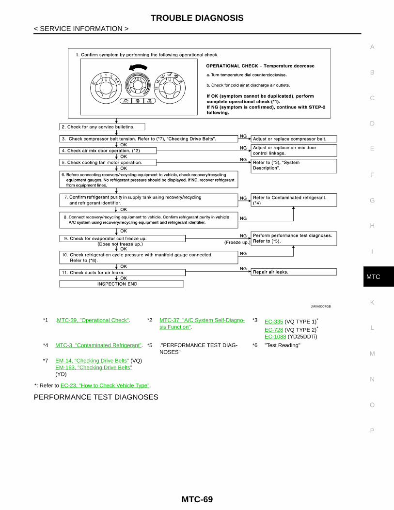
TROUBLE DIAGNOSIS
C
D
E
F
G
H
I
K
L
M
A
B
TC
N
O
P
< SERVICE INFORMATION >
M
*: Refer to EC-23, "How to Check Vehicle Type".
PERFORMANCE TEST DIAGNOSES
*1 .MTC-39, "Operational Check". *2 MTC-37, "A/C System Self-Diagno-sis Function".
*3 EC-335 (VQ TYPE 1)*
EC-728 (VQ TYPE 2)*
EC-1088 (YD25DDTi)
*4 MTC-3, "Contaminated Refrigerant". *5 ."PERFORMANCE TEST DIAG-NOSES"
*6 "Test Reading"
*7 EM-14, "Checking Drive Belts" (VQ)EM-153, "Checking Drive Belts" (YD)
JMIIA0007GB
MTC-69
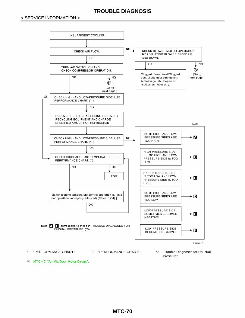
TROUBLE DIAGNOSIS
< SERVICE INFORMATION >*1 "PERFORMANCE CHART". *2 "PERFORMANCE CHART". *3 "Trouble Diagnoses for Unusual Pressure".
*4 MTC-47, "Air Mix Door Motor Circuit".
RJIA1601E
MTC-70

TROUBLE DIAGNOSIS
C
D
E
F
G
H
I
K
L
M
A
B
TC
N
O
P
< SERVICE INFORMATION >
M
PERFORMANCE CHART
Test ConditionTesting must be performed as follows:
*1 MTC-105, "Removal and Installation for Compressor Clutch".
*2 MTC-55, "Front Blower Motor Cir-cuit".
*3 EM-14, "Checking Drive Belts" (VQ)EM-153, "Checking Drive Belts" (YD)
WJIA0361E
MTC-71

TROUBLE DIAGNOSIS
< SERVICE INFORMATION >Test ReadingRecirculating-to-discharge Air Temperature Table
Ambient Air Temperature-to-operating Pressure Table
TROUBLE DIAGNOSES FOR UNUSUAL PRESSUREWhenever system′s high and/or low side pressure is unusual, diagnose using a manifold gauge. The markerabove the gauge scale in the following tables indicates the standard (usual) pressure range. Since the stan-
Vehicle location Indoors or in the shade (in a well-ventilated place)
Doors Closed
Door window Open
Hood Open
TEMP. Max. COLD
Mode switch (Ventilation) set
Recirculation (REC) switch (Recirculation) set
Blower speed Max. speed set
Engine speed Idle speed
Operate the air conditioning system for 10 minutes before taking measurements.
Inside air (Recirculating air) at blower assembly inletDischarge air temperature at center ventilator
°C (°F)Relative humidity%
Air temperature°C (°F)
40 - 60
20 (68) 4.9 - 6.9 (41 - 44)
25 (77) 8.1 - 10.8 (47- 51)
30 (86) 12.1 - 15.1 (54 - 59)
35 (95) 16.9 - 20.5 (62 - 69)
60 - 80
20 (68) 6.9 - 8.8 (44 - 48)
25 (77) 10.6 - 13.1 (51 - 56)
30 (86) 15.1 - 18.2 (59 - 65)
35 (95) 20.5 - 24.0 (69 - 75)
Ambient airHigh-pressure (Discharge side)
kPa (kg/cm2, psi)
Low-pressure (Suction side)
kPa (kg/cm2, psi)Relative humidity%
Air temperature°C (°F)
40 - 60
20 (68)920 - 1,020
(9.38 - 10.40, 133.4 - 147.9)190 - 210
(1.94 - 2.14, 27.5 - 30.4)
25 (77)1,250 - 1,390
(12.74 - 14.17, 181.2 - 201.5)240 - 270
(2.45 - 2.75, 34.8 - 39.1)
30 (86)1,590 - 1,770
(16.21 - 18.04, 230.5 - 256.6)300 - 330
(3.06 - 3.36, 43.5 - 47.8)
35 (95)1,900 - 2,110
(19.37 - 21.51, 275.4 - 305.9)360 - 400
(3.67 - 4.08, 52.2 - 58.0)
60 - 80
20 (68)1,020 - 1,120
(10.40 - 11.42, 147.9 - 162.3)210 - 230
(2.14 - 2.34, 30.4 - 33.3)
25 (77)1,390 - 1,530
(14.17 - 15.60, 201.5 - 221.8)270 - 300
(2.75 - 3.06, 39.1 - 43.5)
30 (86)1,770 - 1,950
(18.04 - 19.88, 256.6 - 282.7)330 - 360
(3.36 - 3.67, 47.8 - 52.2)
35 (95)2,110 - 2,320
(21.51 - 23.65, 305.9 - 336.3)400 - 440
(4.08 - 4.49, 58.0 - 63.8)
MTC-72

TROUBLE DIAGNOSIS
C
D
E
F
G
H
I
K
L
M
A
B
TC
N
O
P
< SERVICE INFORMATION >
M
dard (usual) pressure, however, differs from vehicle to vehicle, refer to above table (Ambient air temperature-to-operating pressure table).
Both High- and Low-pressure Sides are Too High
High-pressure Side is Too High and Low-pressure Side is Too Low
High-pressure Side is Too Low and Low-pressure Side is Too High
Gauge indication Refrigerant cycle Probable cause Corrective action
Both high- and low-pressure sides are too high.
Pressure is reduced soon af-ter water is splashed on con-denser.
Excessive refrigerant charge in refrigeration cycle
Reduce refrigerant until speci-fied pressure is obtained.
Air suction by cooling fan is in-sufficient.
Insufficient condenser cooling performance↓1. Condenser fins are
clogged.2. Improper fan rotation of
cooling fan
• Clean condenser.• Check and repair cooling fan
as necessary.
• Low-pressure pipe is not cold.
• When compressor is stopped high-pressure val-ue quickly drops by approx-
imately 196 kPa (2 kg/cm2, 28 psi). It then decreases gradually thereafter.
Poor heat exchange in con-denser(After compressor operation stops, high-pressure decreas-es too slowly.)↓Air in refrigeration cycle
Evacuate repeatedly and re-charge system.
Engine tends to overheat.Engine cooling systems mal-function.
Check and repair engine cool-ing system.
• An area of the low-pressure pipe is colder than areas near the evaporator outlet.
• Plates are sometimes cov-ered with frost.
• Excessive liquid refrigerant on low-pressure side
• Excessive refrigerant dis-charge flow
• Expansion valve is open a lit-tle compared with the speci-fication.
↓Improper expansion valve ad-justment
Replace expansion valve.
AC359A
Gauge indication Refrigerant cycle Probable cause Corrective action
High-pressure side is too high and low-pressure side is too low.
Upper side of condenser and high-pressure side are hot, however, liquid tank is not so hot.
High-pressure tube or parts lo-cated between compressor and condenser are clogged or crushed.
• Check and repair or replace malfunctioning parts.
• Check lubricant for contami-nation.
AC360A
MTC-73

TROUBLE DIAGNOSIS
< SERVICE INFORMATION >Both High- and Low-pressure Sides are Too Low
Low-pressure Side Sometimes Becomes Negative
Gauge indication Refrigerant cycle Probable cause Corrective action
High-pressure side is too low and low-pressure side is too high. High- and low-pressure sides
become equal soon after com-pressor operation stops.
Compressor pressure opera-tion is improper.↓Damaged inside compressor packings.
Replace compressor.
No temperature difference be-tween high- and low-pressure sides.
Compressor pressure opera-tion is improper.↓Damaged inside compressor packings.
Replace compressor.
AC356A
Gauge indication Refrigerant cycle Probable cause Corrective action
Both high- and low-pressure sides are too low.
• There is a big temperature difference between receiver drier outlet and inlet. Outlet temperature is extremely low.
• Liquid tank inlet and expan-sion valve are frosted.
Liquid tank inside is slightly clogged.
• Replace liquid tank.• Check lubricant for contami-
nation.
• Temperature of expansion valve inlet is extremely low as compared with areas near liquid tank.
• Expansion valve inlet may be frosted.
• Temperature difference oc-curs somewhere in high-pressure side.
High-pressure pipe located be-tween receiver drier and ex-pansion valve is clogged.
• Check and repair malfunc-tioning parts.
• Check lubricant for contami-nation.
Expansion valve and liquid tank are warm or only cool when touched.
Low refrigerant charge.↓Leaking fittings or compo-nents.
Check refrigerant system for leaks. Refer to MTC-112, "Checking of Refrigerant Leaks"
There is a big temperature dif-ference between expansion valve inlet and outlet while the valve itself is frosted.
Expansion valve closes a little compared with the specifica-tion.↓1. Improper expansion
valve adjustment.2. Malfunctioning expansion
valve.3. Outlet and inlet may be
clogged.
• Remove foreign particles by using compressed air.
• Check lubricant for contami-nation.
An area of the low-pressure pipe is colder than areas near the evaporator outlet.
Low-pressure pipe is clogged or crushed.
• Check and repair malfunc-tioning parts.
• Check lubricant for contami-nation.
Air flow volume is too low. Evaporator is frozen.
• Check intake sensor circuit.Refer to MTC-78, "Intake Sensor Circuit".
• Replace compressor.
AC353A
MTC-74

TROUBLE DIAGNOSIS
C
D
E
F
G
H
I
K
L
M
A
B
TC
N
O
P
< SERVICE INFORMATION >
M
Low-pressure Side Becomes Negative
Insufficient Heating INFOID:0000000006108200
SYMPTOM: Insufficient heating
INSPECTION FLOW
Gauge indication Refrigerant cycle Probable cause Corrective action
Low-pressure side sometimes be-comes negative. • Air conditioning system does
not function and does not cy-clically cool the compart-ment air.
• The system constantly func-tions for a certain period of time after compressor is stopped and restarted.
Refrigerant does not discharge cyclically.↓Moisture is frozen at expan-sion valve outlet and inlet.↓Water is mixed with refrigerant.
• Drain water from refrigerant or replace refrigerant.
• Replace liquid tank.
AC354A
Gauge indication Refrigerant cycle Probable cause Corrective action
Low-pressure side becomes nega-tive.
Liquid tank or front/rear side of expansion valve′s pipe is frost-ed or dewed.
High-pressure side is closed and refrigerant does not flow.↓Expansion valve or liquid tank is frosted.
Leave the system at rest until no frost is present. Start it again to check whether or not the malfunction is caused by water or foreign particles.• If water is the cause, initially
cooling is okay. Then the wa-ter freezes causing a block-age. Drain water from refrigerant or replace refrig-erant.
• If due to foreign particles, re-move expansion valve and remove the particles with dry and compressed air (not shop air).
• If either of the above meth-ods cannot correct the mal-function, replace expansion valve.
• Replace liquid tank.• Check lubricant for contami-
nation.
AC362A
MTC-75

TROUBLE DIAGNOSIS
< SERVICE INFORMATION >*: Refer to EC-23, "How to Check Vehicle Type".
Noise INFOID:0000000006108201
SYMPTOM: Noise
INSPECTION FLOW
*1 .MTC-39, "Operational Check". *2 MTC-47, "Air Mix Door Motor Circuit". *3 MTC-37, "A/C System Self-Diagno-sis Function".
*4 MTC-37, "A/C System Self-Diagno-sis Function".
*5 MTC-55, "Front Blower Motor Cir-cuit".
*6 EC-176, "Diagnosis Procedure" (VQ
TYPE 1)*
EC-645, "Diagnosis Procedure" (VQ
TYPE 2)*
EC-1077, "Diagnosis Procedure" (YD25DDTi)
*7 CO-10, "Changing Engine Coolant" (VQ)CO-38, "Changing Engine Coolant" (YD)
*8 MTC-89, "Removal and Installation"
MJIB0354E
MTC-76
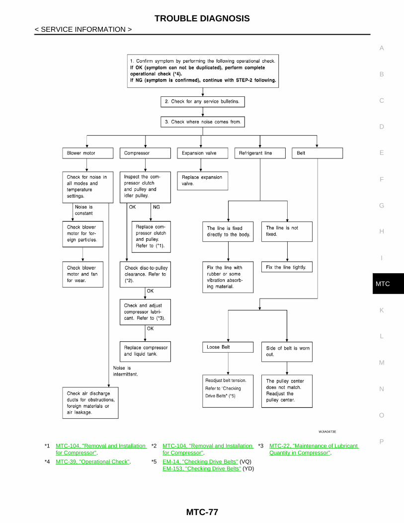
TROUBLE DIAGNOSIS
C
D
E
F
G
H
I
K
L
M
A
B
TC
N
O
P
< SERVICE INFORMATION >
M
*1 MTC-104, "Removal and Installation for Compressor".
*2 MTC-104, "Removal and Installation for Compressor".
*3 MTC-22, "Maintenance of Lubricant Quantity in Compressor".
*4 MTC-39, "Operational Check". *5 EM-14, "Checking Drive Belts" (VQ)EM-153, "Checking Drive Belts" (YD)
WJIA0473E
MTC-77

TROUBLE DIAGNOSIS
< SERVICE INFORMATION >Self-Diagnosis INFOID:0000000006108202
SYMPTOM: Self-diagnosis cannot be performed (Vehicles equipped with NAVI only).
INSPECTION FLOW
Intake Sensor Circuit INFOID:0000000006108203
COMPONENT DESCRIPTION
Intake SensorThe intake sensor is located on the heater & cooling unit. It convertstemperature of air after it passes through the evaporator into a resis-tance value which is then input to the front air control.NOTE:This illustration is for LHD models.The layout for RHD models is symmetrically opposite.
DIAGNOSTIC PROCEDURE FOR INTAKE SENSOR
*1 MTC-40, "Power Supply and Ground Circuit for Front Air Control".
*2 MTC-47, "Air Mix Door Motor Circuit". *3 MTC-78, "Intake Sensor Circuit".
*4 “DIAGNOSTIC PROCEDURE FOR AIR MIX DOOR MOTOR (FRONT)”.
*5 MTC-39, "Operational Check". *6 “SYMPTOM TABLE”.
MJIB0246E
MJIB0198E
MTC-78

TROUBLE DIAGNOSIS
C
D
E
F
G
H
I
K
L
M
A
B
TC
N
O
P
< SERVICE INFORMATION >
M
SYMPTOM: Intake sensor circuit is open or shorted. (56 or 57 is indi-cated on front air control as a result of conducting Self-diagnosis).
1.CHECK VOLTAGE BETWEEN INTAKE SENSOR AND GROUND
1. Turn ignition switch OFF.2. Disconnect intake sensor connector.3. Turn ignition switch ON.4. Check voltage between intake sensor harness connector M82
terminal 2 and ground.
OK or NGOK >> GO TO 2.NG >> GO TO 4.
2.CHECK CIRCUIT CONTINUITY BETWEEN INTAKE SENSOR AND FRONT AIR CONTROL
1. Turn ignition switch OFF.2. Disconnect front air control connector.3. Check continuity between intake sensor harness connector M82
terminal 1 and front air control harness connector M129 terminal13.
4. Check continuity between intake sensor harness connector M82terminal 1 and ground.
OK or NGOK >> GO TO 3.NG >> Repair or replace harness or connector.
3.CHECK INTAKE SENSOR
Refer to "COMPONENT INSPECTION".OK or NGOK >> Replace front air control.NG >> Replace intake sensor.
4.CHECK CIRCUIT CONTINUITY BETWEEN INTAKE SENSOR AND FRONT AIR CONTROL
WJIA1156E
2 - Ground : Approx. 5V
WJIA1278E
1 - 13 : Continuity should exist.
1 - Ground : Continuity should not exist. JMIIA0097GB
MTC-79

TROUBLE DIAGNOSIS
< SERVICE INFORMATION >1. Turn ignition switch OFF.2. Disconnect front air control connector.3. Check continuity between intake sensor harness connector M82terminal 2 and front air control harness connector M129 terminal12.
4. Check continuity between intake sensor harness connector M82terminal 2 and ground.
OK or NGOK >> Replace front air control.NG >> Repair or replace harness or connector.
COMPONENT INSPECTION
Intake SensorAfter disconnecting intake sensor connector, measure resistancebetween terminals 1 and 2 at sensor harness side, using the tablebelow.
NOTE:This illustration is for LHD models.The layout for RHD models is symmetrically opposite.
2 - 12 : Continuity should exist.
2 - Ground : Continuity should not exist. WJIA1158E
Temperature °C (°F) Resistance kΩ
−15 (5) 209.0
−10 (14) 160.0
−5 (23) 123.0
0 (32) 95.8
5 (41) 74.9
10 (50) 58.9
15 (59) 46.7
20 (68) 37.3
25 (77) 30.0
30 (86) 24.2
35 (95) 19.7
40 (104) 16.1
45 (113) 13.2JMIIA0098GB
MTC-80

CONTROL UNIT
C
D
E
F
G
H
I
K
L
M
A
B
TC
N
O
P
< SERVICE INFORMATION >
M
CONTROL UNIT
Removal and Installation INFOID:0000000006108205
Removal and Installation of Front Air Control
REMOVAL
1. Remove the five control knobs from the front air control unit.2. Remove the cluster lid C. Refer to IP-11, "Removal and Installation".3. Remove the four screws securing the front air control unit to the
cluster lid C.4. Remove the front air control unit.
INSTALLATIONInstall in the reverse order of removal.
LJIA0130E
MTC-81

INTAKE SENSOR
< SERVICE INFORMATION >INTAKE SENSOR
Removal and Installation INFOID:0000000006108206
REMOVAL1. Remove the instrument panel. Refer to IP-11, "Removal and Installation".2. Disconnect the intake sensor electrical connector.
NOTE:The intake sensor is located on the top of the heater and coolingunit assembly next to the A/C evaporator cover.
3. Twist the intake sensor to remove the intake sensor from theheater and cooling unit assembly.
INSTALLATIONInstall in the reverse order of removal.
MJIB0325E
MTC-82

BLOWER MOTOR
C
D
E
F
G
H
I
K
L
M
A
B
TC
N
O
P
< SERVICE INFORMATION >
M
BLOWER MOTOR
Component INFOID:0000000006108207
Removal and Installation INFOID:0000000006108208
FRONT BLOWER MOTOR
REMOVAL
1. Remove the glove box assembly. Refer to IP-11, "Removal and Installation".2. Disconnect the blower motor electrical connector.3. Remove the three screws, and then remove the blower motor.
INSTALLATIONInstall in the reverse order of removal.
1. Heater and cooling unit assembly 2. Blower motor 3. Blower motor resistor
MJIB0247E
MTC-83

AIR CONDITIONER FILTER
< SERVICE INFORMATION >AIR CONDITIONER FILTER
Removal and Installation INFOID:0000000006108209
FUNCTIONThe air inside the passenger compartment is filtered by the air condi-tioner filters when the heater or A/C controls are set on either therecirculation or fresh mode. The two air conditioner filters are locatedin the heater and cooling unit assembly.
REPLACEMENT TIMINGReplacement of the two air conditioner filters is recommended on a regular interval depending on the drivingconditions. Refer to MA-7. It may also be necessary to replace the two air conditioner filters as part of a com-ponent replacement if the air conditioner filters are damaged.
REPLACEMENT PROCEDURE1. Remove the glove box assembly.a. Remove the two lower glove box screws.
b. Open the glove box, and then remove the four upper glove boxscrews.NOTE:It is not necessary to remove the two glove box striker screws.
c. Remove the glove box assembly from the instrument panel toaccess the air conditioner filter cover.
2. Remove the screw, and then remove the air conditioner filtercover.
3. Remove the air conditioner filters from the heater and coolingunit assembly housing.
MJIB0215E
LJIA0146E
WJIA0628E
MJIB0216E
MTC-84
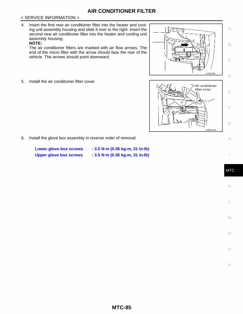
AIR CONDITIONER FILTER
C
D
E
F
G
H
I
K
L
M
A
B
TC
N
O
P
< SERVICE INFORMATION >
M
4. Insert the first new air conditioner filter into the heater and cool-ing unit assembly housing and slide it over to the right. Insert thesecond new air conditioner filter into the heater and cooling unitassembly housing.NOTE:The air conditioner filters are marked with air flow arrows. Theend of the micro filter with the arrow should face the rear of thevehicle. The arrows should point downward.
5. Install the air conditioner filter cover.
6. Install the glove box assembly in reverse order of removal.
LJIA0148E
MJIB0216E
Lower glove box screws : 3.5 N·m (0.36 kg-m, 31 in-lb)Upper glove box screws : 3.5 N·m (0.36 kg-m, 31 in-lb)
MTC-85

HEATER & COOLING UNIT ASSEMBLY
< SERVICE INFORMATION >HEATER & COOLING UNIT ASSEMBLY
Component INFOID:0000000006108210
Heater and Cooling Unit Assembly —LHD Models—
MJIB0278E
1. High-pressure A/C pipe 2. Low-pressure A/C pipe 3. Expansion valve
4. Heater core and evaporator pipes grommet
5. A/C drain hose grommet 6. A/C drain hose
7. Heater core pipes 8. Coolant reservoir hose 9. Heater and cooling unit assembly
MTC-86
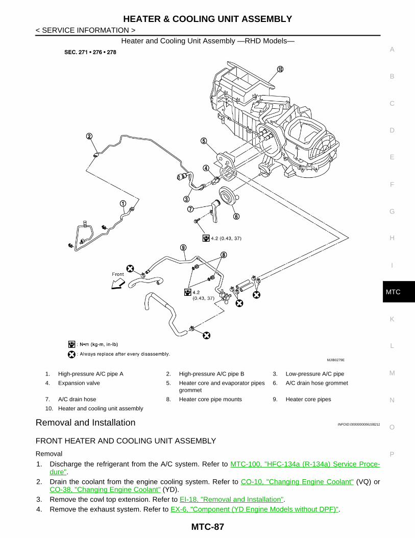
HEATER & COOLING UNIT ASSEMBLY
C
D
E
F
G
H
I
K
L
M
A
B
TC
N
O
P
< SERVICE INFORMATION >
M
Heater and Cooling Unit Assembly —RHD Models—
Removal and Installation INFOID:0000000006108211
FRONT HEATER AND COOLING UNIT ASSEMBLY
Removal
1. Discharge the refrigerant from the A/C system. Refer to MTC-100, "HFC-134a (R-134a) Service Proce-dure".
2. Drain the coolant from the engine cooling system. Refer to CO-10, "Changing Engine Coolant" (VQ) orCO-38, "Changing Engine Coolant" (YD).
3. Remove the cowl top extension. Refer to EI-18, "Removal and Installation".4. Remove the exhaust system. Refer to EX-6, "Component (YD Engine Models without DPF)".
MJIB0279E
1. High-pressure A/C pipe A 2. High-pressure A/C pipe B 3. Low-pressure A/C pipe
4. Expansion valve 5. Heater core and evaporator pipes grommet
6. A/C drain hose grommet
7. A/C drain hose 8. Heater core pipe mounts 9. Heater core pipes
10. Heater and cooling unit assembly
MTC-87

HEATER & COOLING UNIT ASSEMBLY
< SERVICE INFORMATION >5. Disconnect the heater hoses from the heater core.6. Disconnect the high/low pressure pipes from the expansion valve.7. Move the two front seats to the rear most position on the seat track.8. Remove the instrument panel and console panel. Refer to IP-11, "Removal and Installation".9. Remove the steering column. Refer to PS-12, "Removal and Installation".10. Disconnect the instrument panel wire harness at the RH and LH in-line connector brackets, and the fuseblock (J/B) electrical connectors. Refer to PG-49, "Harness Layout".11. Remove the steering member from each side of the vehicle body.12. Remove the heater and cooling unit assembly with it attached to the steering member, from the vehicle.
CAUTION:Use care not to damage the seats and interior trim panels when removing the heater and coolingunit assembly with it attached to the steering member.
13. Remove the heater and cooling unit assembly from the steering member.
InstallationInstall in the reverse order of removal.CAUTION:• Replace the O-ring of the low-pressure pipe and high-pressure pipe with a new one, and apply com-
pressor oil to it when installing it.• After charging the refrigerant, check for leaks.NOTE:• Fill the engine cooling system with the specified coolant mixture. Refer to CO-10, "Changing Engine Cool-
ant" (VQ) or CO-38, "Changing Engine Coolant" (YD).• Recharge the A/C system. Refer to MTC-100, "HFC-134a (R-134a) Service Procedure".
MTC-88
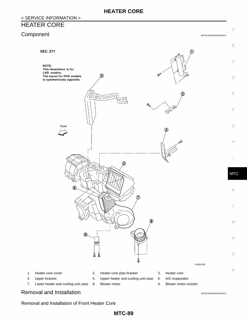
HEATER CORE
C
D
E
F
G
H
I
K
L
M
A
B
TC
N
O
P
< SERVICE INFORMATION >
M
HEATER CORE
Component INFOID:0000000006108212
Removal and Installation INFOID:0000000006108213
Removal and Installation of Front Heater Core
1. Heater core cover 2. Heater core pipe bracket 3. Heater core
4. Upper bracket 5. Upper heater and cooling unit case 6. A/C evaporator
7. Lower heater and cooling unit case 8. Blower motor 9. Blower motor resistor
MJIB0248E
MTC-89

HEATER CORE
< SERVICE INFORMATION >REMOVAL1. Remove the heater and cooling unit assembly. Refer to MTC-86, "Component".2. Remove the four screws, and then remove the upper bracket.3. Remove the four screws, and then remove the heater core cover.4. Remove the heater core pipe bracket.5. Remove the heater core.
NOTE:If the air conditioner filters are contaminated from coolant leak-ing from the heater core, replace the air conditioner filters withnew ones before installing the new heater core.
INSTALLATIONInstall in the reverse order of removal.
MJIB0216E
MTC-90

DEFROSTER DOOR MOTOR
C
D
E
F
G
H
I
K
L
M
A
B
TC
N
O
P
< SERVICE INFORMATION >
M
DEFROSTER DOOR MOTOR
Component INFOID:0000000006108214
Defroster Door Motor - Heater and Cooling Unit Assembly
Removal and Installation INFOID:0000000006108215
REMOVAL1. Remove the steering member.2. Remove the heater and cooling unit assembly. Refer to MTC-86.3. Disconnect the defroster door motor electrical connector.4. Remove the three screws, and then remove the defroster door motor.
INSTALLATIONInstall in the reverse order of removal.
MJIB0249E
1. Heater and cooling unit assembly 2. Intake door motor 3. Air mix door motor
4. Blower motor resistor 5. Mode door motor 6. Defroster door motor
MTC-91

INTAKE DOOR MOTOR
< SERVICE INFORMATION >INTAKE DOOR MOTOR
Component INFOID:0000000006108216
Intake Door Motor - Heater and Cooling Unit Assembly
Removal and Installation INFOID:0000000006108217
REMOVAL1. Remove the steering member.2. Remove the heater and cooling unit assembly. Refer to MTC-86, "Component".3. Disconnect the intake door motor electrical connector.4. Remove the three screws, and then remove the intake door motor.
INSTALLATIONInstall in the reverse order of removal.
MJIB0249E
1. Heater and cooling unit assembly 2. Intake door motor 3. Air mix door motor
4. Blower motor resistor 5. Mode door motor 6. Defroster door motor
MTC-92

MODE DOOR MOTOR
C
D
E
F
G
H
I
K
L
M
A
B
TC
N
O
P
< SERVICE INFORMATION >
M
MODE DOOR MOTOR
Component INFOID:0000000006108218
Mode Door Motor - Heater and Cooling Unit Assembly
Removal and Installation INFOID:0000000006108219
REMOVAL1. Remove the steering member.2. Remove the heater and cooling unit assembly. Refer to MTC-86, "Component".3. Disconnect the mode door motor electrical connector.4. Remove the two screws, and then remove the mode door motor.
INSTALLATIONInstall in the reverse order of removal.
MJIB0249E
1. Heater and cooling unit assembly 2. Intake door motor 3. Air mix door motor
4. Blower motor resistor 5. Mode door motor 6. Defroster door motor
MTC-93

AIR MIX DOOR MOTOR
< SERVICE INFORMATION >AIR MIX DOOR MOTOR
Component INFOID:0000000006108220
Air Mix Door Motor - Heater and Cooling Unit Assembly
Removal and Installation INFOID:0000000006108221
FRONT AIR MIX DOOR MOTOR
Removal
1. Remove the steering member.2. Remove the heater and cooling unit assembly. Refer to MTC-86, "Component".3. Disconnect the air mix door motor electrical connector.4. Remove the three screws, and then remove the air mix door motor.
InstallationInstall in the reverse order of removal.
MJIB0249E
1. Heater and cooling unit assembly 2. Intake door motor 3. Air mix door motor
4. Blower motor resistor 5. Mode door motor 6. Defroster door motor
MTC-94

FRONT BLOWER MOTOR RESISTOR
C
D
E
F
G
H
I
K
L
M
A
B
TC
N
O
P
< SERVICE INFORMATION >
M
FRONT BLOWER MOTOR RESISTOR
Component INFOID:0000000006108222
Blower Motor Resistor - Heater and Cooling Unit Assembly
Removal and Installation INFOID:0000000006108223
REMOVAL1. Remove the steering member.2. Remove the heater and cooling unit assembly. Refer to MTC-86, "Component".3. Disconnect the blower motor resistor electrical connector.4. Remove the two screws, and then remove the blower motor resistor.
INSTALLATIONInstall in the reverse order of removal.
MJIB0249E
1. Heater and cooling unit assembly 2. Intake door motor 3. Air mix door motor
4. Blower motor resistor 5. Mode door motor 6. Defroster door motor
MTC-95

DUCTS AND GRILLES
< SERVICE INFORMATION >DUCTS AND GRILLES
Component INFOID:0000000006108224
Ducts - Heater and Cooling Unit Assembly
MJIB0250E
1. Defroster nozzle 2. Side demister duct LH 3. Ventilator duct LH
4. Side demister duct RH 5. Ventilator duct RH 6. Center ventilator duct
MTC-96

DUCTS AND GRILLES
C
D
E
F
G
H
I
K
L
M
A
B
TC
N
O
P
< SERVICE INFORMATION >
M
Grilles
7. Heater and cooling unit assembly 8. Floor duct 9. Clips
10. Heat duct
JMIIA0008GB
1. Overhead console trim panel 2. Overhead console front grilles (front) 3. Overhead console rear grilles (rear)
4. Instrument panel 5. Storage tray bottom cover LH 6. Side ventilator and demister grille LH
MTC-97

DUCTS AND GRILLES
< SERVICE INFORMATION >Removal and Installation INFOID:0000000006108225
Removal and Installation of Center Console Heat Duct and Rear Finisher Assembly Grille
REMOVALThe center console must be removed and disassembled to remove the heat duct and rear finisher assemblygrille. Refer to IP-21, "Disassembly and Assembly".
INSTALLATIONInstall in the reverse order of removal.
Removal and Installation of Defroster Nozzle
REMOVAL
1. Remove the instrument panel. Refer to IP-11, "Removal and Installation".2. Remove the defroster nozzle.
INSTALLATIONInstall in the reverse order of removal.
Removal and Installation of Side Demister Duct (LH/RH)
REMOVAL
1. Remove the instrument panel. Refer to IP-11, "Removal and Installation".2. Remove the RH or LH side demister duct.
INSTALLATIONInstall in the reverse order of removal.
Removal and Installation of Ventilator Duct (LH/RH)
REMOVAL
1. Remove the instrument panel. Refer to IP-11, "Removal and Installation".2. Remove the RH or LH ventilator duct.
INSTALLATIONInstall in the reverse order of removal.
Removal and Installation of Center Ventilator Duct
REMOVAL
1. Remove the instrument panel. Refer to IP-11, "Removal and Installation".2. Remove the defroster nozzle.3. Remove the RH and LH side demister ducts.4. Remove the RH and LH ventilator ducts.5. Remove the center ventilator duct.
INSTALLATIONInstall in the reverse order of removal.
Removal and Installation of Floor Duct
REMOVAL
1. Remove the floor carpet. Refer to EI-31, "Removal and Installation".2. Remove the two clips, and then remove the floor duct.
INSTALLATIONInstall in the reverse order of removal.
Removal and Installation of Grilles
REMOVAL
7. Ventilator grille LH 8. Ventilator grille RH 9. Side ventilator and demister grille RH
10. Storage tray bottom cover RH
MTC-98

DUCTS AND GRILLES
C
D
E
F
G
H
I
K
L
M
A
B
TC
N
O
P
< SERVICE INFORMATION >
M
1. Remove the interior trim panel as necessary. Refer to EI-29, "Removal and Installation".2. Remove the grille from the interior trim panel.
NOTE:To remove the overhead console front and rear grilles, turn the grille counter-clockwise to release thegrille from the overhead console trim panel.
INSTALLATIONInstall in the reverse order of removal.
MTC-99
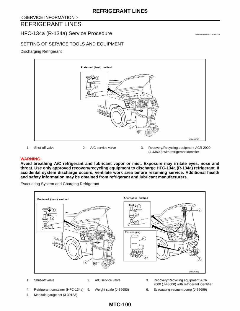
REFRIGERANT LINES
< SERVICE INFORMATION >REFRIGERANT LINES
HFC-134a (R-134a) Service Procedure INFOID:0000000006108226
SETTING OF SERVICE TOOLS AND EQUIPMENT
Discharging Refrigerant
WARNING:Avoid breathing A/C refrigerant and lubricant vapor or mist. Exposure may irritate eyes, nose andthroat. Use only approved recovery/recycling equipment to discharge HFC-134a (R-134a) refrigerant. Ifaccidental system discharge occurs, ventilate work area before resuming service. Additional healthand safety information may be obtained from refrigerant and lubricant manufacturers.
Evacuating System and Charging Refrigerant
1. Shut-off valve 2. A/C service valve 3. Recovery/Recycling equipment ACR 2000 (J-43600) with refrigerant identifier
WJIA0579E
1. Shut-off valve 2. A/C service valve 3. Recovery/Recycling equipment ACR 2000 (J-43600) with refrigerant identifier
4. Refrigerant container (HFC-134a) 5. Weight scale (J-39650) 6. Evacuating vacuum pump (J-39699)
7. Manifold gauge set (J-39183)
WJIA0580E
MTC-100

REFRIGERANT LINES
C
D
E
F
G
H
I
K
L
M
A
B
TC
N
O
P
< SERVICE INFORMATION >
M
*1 MTC-22, "Maintenance of Lubricant Quantity in Compressor".
*2 MTC-112, "Checking of Refrigerant Leaks".
*3 MTC-112, "Checking of Refrigerant Leaks".
*4 MTC-68, "Insufficient Cooling". *5 MTC-3, "Contaminated Refrigerant".
WJIA0530E
MTC-101

REFRIGERANT LINES
< SERVICE INFORMATION >Component INFOID:0000000006108227
A/C Compressor and Condenser —LHD Models—
MJIB0276E
1. High-pressure service valve 2. Clip 3. High-pressure A/C pipe
4. Refrigerant pressure sensor 5. Condenser 6. Compressor shaft seal
7. High-pressure flexible A/C hose 8. Low-pressure flexible A/C hose 9. Low-pressure service valve
10. Low-pressure A/C pipe 11. Expansion valve 12. A/C drain hose
MTC-102

REFRIGERANT LINES
C
D
E
F
G
H
I
K
L
M
A
B
TC
N
O
P
< SERVICE INFORMATION >
M
A/C Compressor and Condenser —RHD Models—
MJIB0277E
1. High-pressure service valve 2. Clip 3. High-pressure A/C pipe
4. Refrigerant pressure sensor 5. Condenser 6. Compressor shaft seal
7. High-pressure flexible A/C hose 8. Low-pressure flexible A/C hose 9. Low-pressure service valve
10. Low-pressure A/C pipe 11. Expansion valve 12. A/C drain hose
MTC-103

REFRIGERANT LINES
< SERVICE INFORMATION >Removal and Installation for Compressor INFOID:0000000006108228
A/C Compressor Mounting
REMOVAL1. Discharge the refrigerant. Refer to MTC-100, "HFC-134a (R-134a) Service Procedure".2. Remove the front right wheel and tire assembly. Refer to WT-5, "Rotation".3. Remove the engine under cover and the splash shield using power tool.4. Remove the engine air cleaner and air ducts. Refer to EM-16, "Removal and Installation" (VQ) or EM-157,
"Removal and Installation" (YD).5. Remove the drive belt. Refer to EM-14, "Removal and Installation" (VQ) or EM-156, "Removal and Instal-
lation" (YD).6. Disconnect the compressor electrical connector.7. Disconnect the high-pressure flexible hose and low-pressure flexible hose from the compressor.
CAUTION:Cap or wrap the joint of the pipe with suitable material such as vinyl tape to avoid the entry of air.
8. Remove the compressor bolts and nut using power tools.
INSTALLATIONInstall in the reverse order of removal.CAUTION:• Replace the O-ring of the low-pressure flexible hose and high-pressure flexible hose with a new one,
apply compressor oil to the O-rings before installation.• After recharging the A/C system with refrigerant, check for leaks.• Always tighten the mounting bolts to the specified torque.
MJIB0179E
1. Compressor 2. Alternator and A/C compressor bracket
3. Timing chain case
4. Cylinder block
MTC-104

REFRIGERANT LINES
C
D
E
F
G
H
I
K
L
M
A
B
TC
N
O
P
< SERVICE INFORMATION >
M
Removal and Installation for Compressor Clutch INFOID:0000000006108229
Magnet Clutch Assembly
REMOVAL1. Remove the compressor. Refer to MTC-104, "Removal and Installation for Compressor"2. Remove the center bolt while holding the clutch disc stationary
using Tool as shown.
3. Remove the clutch disc.
4. Remove the snap ring using external snap ring pliers or suitabletool.
WJIA0372E
1. Magnet clutch assembly 2. Magnet coil 3. Pulley
4. Clutch disc 5. Snap ring 6. Thermal protector (built in)
7. Compressor
Tool number : J-44614
WHA228
RHA072C
MTC-105

REFRIGERANT LINES
< SERVICE INFORMATION >5. Remove the pulley using Tool with a small adapter. Position thesmall adapter on the end of the drive shaft and the center of thepuller on the small adapter.CAUTION:To prevent deformation of the pulley groove, the pullerclaws should be hooked under the pulley groove and notinto the pulley groove.
6. Remove the magnet coil harness clip using a screwdriver,remove the three magnet coil fixing screws, and then removethe magnet coil.
INSPECTION
Clutch DiscIf the contact surface shows signs of damage due to excessive heat,replace clutch disc and pulley.
PulleyCheck the appearance of the pulley assembly. If contact surface of pulley shows signs of excessive grooving,replace clutch disc and pulley. The contact surfaces of the pulley assembly should be cleaned with a suitablesolvent before reinstallation.
CoilCheck magnet coil for loose connections or any cracked insulation.
INSTALLATION1. Install the magnet coil.
CAUTION:Be sure to align the magnet coil pin with the hole in thecompressor front head.
2. Install the magnet coil harness clip using a screwdriver.
LHA173
WHA212
WHA183
WHA213
MTC-106

REFRIGERANT LINES
C
D
E
F
G
H
I
K
L
M
A
B
TC
N
O
P
< SERVICE INFORMATION >
M
3. Install the pulley assembly using Tool and a wrench, then installthe snap ring using snap ring pliers.
4. Install the clutch disc on the compressor shaft, together with theoriginal shim(s). Press the clutch disc down by hand.
5. Install the clutch pulley bolt using Tool, to prevent the clutch discfrom turning and tighten the bolt to specification. Refer to MTC-102, "Component".
CAUTION:After tightening the clutch pulley bolt, check that the clutchpulley rotates smoothly.
6. Check the pulley clearance all the way around the clutch disc asshown.
7. If the specified clearance is not obtained, replace the adjustingspacer to readjust.
8. Connect the compressor electrical connector.9. Install the drive belt. Refer to EM-14, "Removal and Installation"
(VQ) or EM-156, "Removal and Installation" (YD).10. Install the engine under cover and the splash shield.
Tool number : KV99106200
MJIB0290E
WHA184
Tool number : J-44614
WHA229
Clutch disc-to-pulley clearance : 0.3 - 0.6 mm (0.012 - 0.024 in)
WHA194
MTC-107
REFRIGERANT LINES
< SERVICE INFORMATION >BREAK-IN OPERATIONWhen replacing compressor clutch assembly, always conduct the break-in operation. This is done by engag-ing and disengaging the clutch about 30 times. Break-in operation raises the level of transmitted torque.
Removal and Installation for Low-Pressure Flexible Hose INFOID:0000000006108230
REMOVAL1. Remove the engine room cover using power tools.2. Remove the engine air cleaner and air ducts. Refer to EM-16, "Removal and Installation" (VQ) or EM-157,
"Removal and Installation" (YD).3. Remove the cowl top extension. Refer to EI-18, "Removal and Installation". 4. Discharge the refrigerant. Refer to MTC-100, "HFC-134a (R-134a) Service Procedure".
CAUTION:Cap or wrap the joint of the pipe with suitable material such as vinyl tape to avoid the entry of air.
5. Remove the low-pressure flexible hose. Refer to MTC-102, "Component".
INSTALLATIONInstall in the reverse order of removal.NOTE:Refer to MTC-102, "Component".CAUTION:• Replace the O-ring of the low-pressure flexible hose with a new one, then apply compressor oil to it
when installing it.• After charging refrigerant, check for leaks.• Always tighten the mounting bolts to the specified torque.
Removal and Installation for High-pressure Flexible Hose INFOID:0000000006108231
REMOVAL1. Remove the engine under cover.2. Remove the engine air cleaner and air ducts. Refer to EM-16, "Removal and Installation" (VQ) or EM-157,
"Removal and Installation" (YD).3. Discharge the refrigerant. Refer to MTC-100, "HFC-134a (R-134a) Service Procedure".4. Remove the high-pressure flexible hose. Refer to MTC-102, "Component".
CAUTION:Cap or wrap the joint of the pipe with suitable material such as vinyl tape to avoid the entry of air.
INSTALLATIONInstall in the reverse order of removal.NOTE:Refer to MTC-102, "Component".CAUTION:• Replace the O-ring of the high-pressure flexible hose with a new one, then apply compressor oil to it
when installing it.• After charging refrigerant, check for leaks.• Always tighten the mounting bolts to the specified torque.
Removal and Installation for High-pressure Pipe INFOID:0000000006108232
REMOVAL1. Remove the cowl top extension. Refer to EI-18, "Removal and Installation". 2. Disconnect the battery negative cable.3. Reposition the IPDM E/R aside.4. Remove the front right wheel and tire assembly. Refer to WT-5, "Rotation".5. Position aside the front floor insulator.6. Discharge the refrigerant. Refer to MTC-100, "HFC-134a (R-134a) Service Procedure".7. Remove the low pressure pipe. Refer to MTC-109, "Removal and Installation for Low-Pressure Pipe".
MTC-108

REFRIGERANT LINES
C
D
E
F
G
H
I
K
L
M
A
B
TC
N
O
P
< SERVICE INFORMATION >
M
8. Remove the high-pressure pipe. Refer to MTC-102, "Component".CAUTION:Cap or wrap the joint of the pipe with suitable material such as vinyl tape to avoid the entry of air.
INSTALLATIONInstall in the reverse order of removal.NOTE:Refer to MTC-102, "Component".CAUTION:• Replace the O-ring of the high-pressure pipe with a new one, then apply compressor oil to it when
installing it.• After charging refrigerant, check for leaks.• Always tighten the mounting bolts to the specified torque.
Removal and Installation for Low-Pressure Pipe INFOID:0000000006108233
REMOVAL1. Discharge the refrigerant. Refer to MTC-100, "HFC-134a (R-134a) Service Procedure".2. Remove the cowl top and the cowl top extension. Refer to EI-18, "Removal and Installation".3. Remove the low-pressure pipe. Refer to MTC-102, "Component".
CAUTION:Cap or wrap the joint of the pipes with suitable material such as vinyl tape to avoid the entry of air.
INSTALLATIONInstall in the reverse order of removal.NOTE:Refer to MTC-102, "Component".CAUTION:• Replace the O-ring of the high/low-pressure pipe with a new one, then apply compressor oil to it
when installing it.• After charging refrigerant, check for leaks.• Always tighten the mounting bolts to the specified torque.
Removal and Installation for Refrigerant Pressure Sensor INFOID:0000000006108234
REMOVAL1. Discharge the refrigerant. Refer to MTC-100, "HFC-134a (R-134a) Service Procedure".2. Disconnect the refrigerant pressure sensor electrical connector,
and then remove the refrigerant pressure sensor from the con-denser.CAUTION:Be careful not to damage the condenser fins.
INSTALLATIONInstall in the reverse order of removal.NOTE:Refer to MTC-102, "Component".CAUTION:• Be careful not to damage the condenser fins.• Apply compressor oil to the O-ring of the refrigerant pressure sensor when installing it.• After charging refrigerant, check for leaks.
LJIA0145E
MTC-109
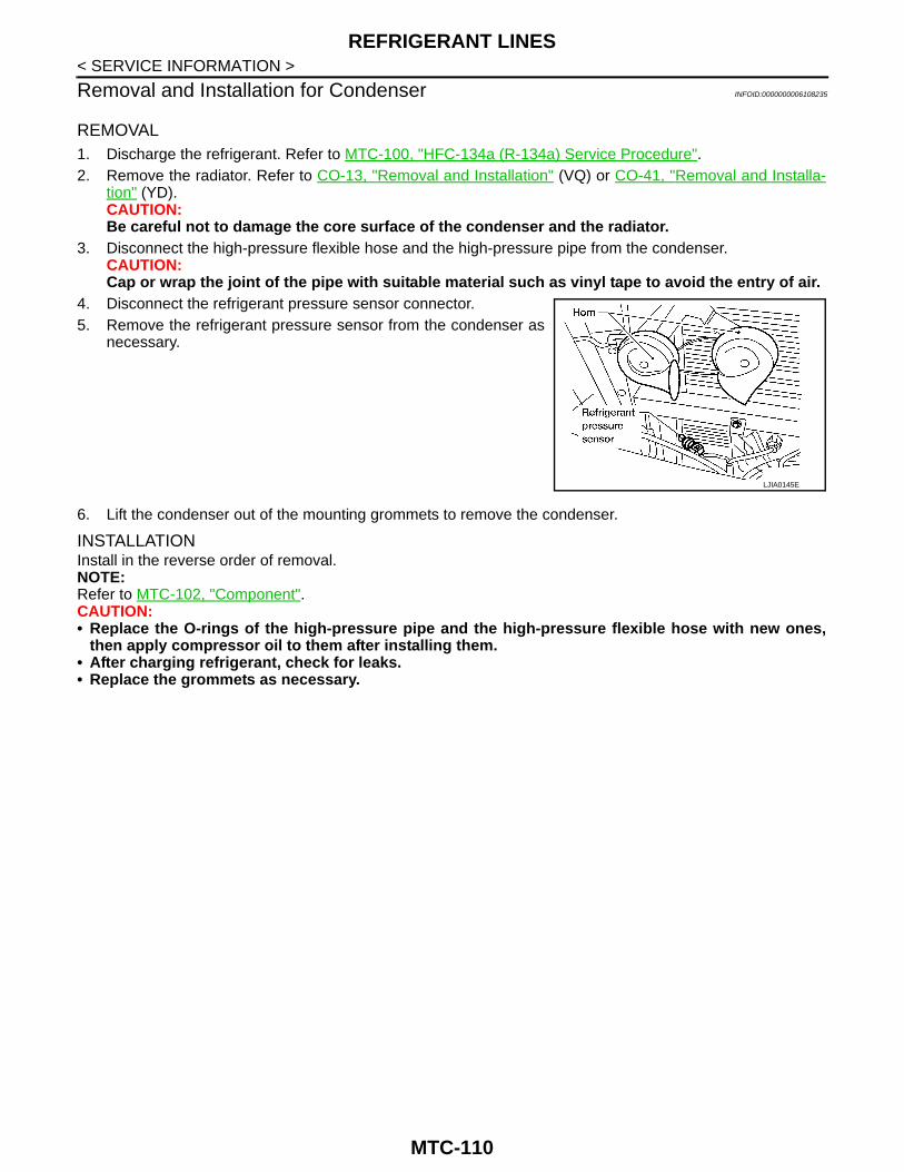
REFRIGERANT LINES
< SERVICE INFORMATION >Removal and Installation for Condenser INFOID:0000000006108235
REMOVAL1. Discharge the refrigerant. Refer to MTC-100, "HFC-134a (R-134a) Service Procedure".2. Remove the radiator. Refer to CO-13, "Removal and Installation" (VQ) or CO-41, "Removal and Installa-
tion" (YD).CAUTION:Be careful not to damage the core surface of the condenser and the radiator.
3. Disconnect the high-pressure flexible hose and the high-pressure pipe from the condenser.CAUTION:Cap or wrap the joint of the pipe with suitable material such as vinyl tape to avoid the entry of air.
4. Disconnect the refrigerant pressure sensor connector.5. Remove the refrigerant pressure sensor from the condenser as
necessary.
6. Lift the condenser out of the mounting grommets to remove the condenser.
INSTALLATIONInstall in the reverse order of removal.NOTE:Refer to MTC-102, "Component".CAUTION:• Replace the O-rings of the high-pressure pipe and the high-pressure flexible hose with new ones,
then apply compressor oil to them after installing them.• After charging refrigerant, check for leaks.• Replace the grommets as necessary.
LJIA0145E
MTC-110

REFRIGERANT LINES
C
D
E
F
G
H
I
K
L
M
A
B
TC
N
O
P
< SERVICE INFORMATION >
M
Removal and Installation for Evaporator INFOID:0000000006108236
Heater and Cooling Unit Assembly
REMOVAL1. Remove the heater core. Refer to MTC-89.2. Remove the defroster mode door arm.3. Separate the heater core and cooling unit case.
MJIB0252E
1. Heater core cover 2. Heater core pipe bracket 3. Heater core
4. Upper bracket 5. Upper heater and cooling unit case 6. A/C evaporator
7. Lower heater and cooling unit case 8. Blower motor 9. Blower motor resistor
MTC-111

REFRIGERANT LINES
< SERVICE INFORMATION >4. Remove the evaporator.INSTALLATIONInstall in the reverse order of removal.CAUTION:Replace the O-rings on the low-pressure flexible hose and the high-pressure pipe with new ones.Apply compressor oil to the O-rings before installing them.
Removal and Installation for Expansion Valve INFOID:0000000006108237
REMOVAL1. Discharge the refrigerant. Refer to MTC-100, "HFC-134a (R-134a) Service Procedure".2. Remove the heater and cooling unit assembly. Refer to MTC-86.3. Remove the cooler grommet.4. Remove the expansion valve.
INSTALLATIONInstall in the reverse order of removal.
CAUTION:• Replace the O-rings on the A/C refrigerant pipes with new ones, then apply compressor oil to them
when installing them.• After charging refrigerant, check for leaks.• Always tighten the mounting bolts to the specified torque.
Checking of Refrigerant Leaks INFOID:0000000006108238
Perform a visual inspection of all refrigeration parts, fittings, hoses and components for signs of A/C lubricantleakage, damage and corrosion. A/C lubricant leakage may indicate an area of refrigerant leakage. Allowextra inspection time in these areas when using either an electronic refrigerant leak detector or fluorescentdye leak detector.If dye is observed, confirm the leak with an electronic refrigerant leak detector. It is possible a prior leak wasrepaired and not properly cleaned.When searching for leaks, do not stop when one leak is found but continue to check for additional leaks at allsystem components and connections.When searching for refrigerant leaks using an electronic leak detector, move the probe along the suspectedleak area at 1 to 2 inches per second and no further than 1/4 inch from the component.CAUTION:Moving the electronic leak detector probe slower and closer to the suspected leak area will improvethe chances of finding a leak.
Checking System for Leaks Using the Fluorescent Leak Detector INFOID:0000000006108239
1. Check A/C system for leaks using the UV lamp and safety goggles [SST: J-42220] in a less sunlight area(area without windows preferable). Illuminate all components, fittings and lines. The dye will appear as abright green/yellow area at the point of leakage. Fluorescent dye observed at the evaporator drain open-ing indicates an evaporator core assembly (tubes, core or expansion valve) leak.
2. If the suspected area is difficult to see, use an adjustable mirror or wipe the area with a clean shop rag orcloth, with the UV lamp for dye residue.
WJIA0582E
Expansion valve bolts : 4.0 N·m (0.41 kg-m, 35 in-lb)A/C refrigerant pipe to expansion valve bolt : Refer to MTC-102, "Component".
MTC-112

REFRIGERANT LINES
C
D
E
F
G
H
I
K
L
M
A
B
TC
N
O
P
< SERVICE INFORMATION >
M
3. After the leak is repaired, remove any residual dye using dye cleaner [SST: J-43872] to prevent future mis-diagnosis.
4. Perform a system performance check and verify the leak repair with an approved electronic refrigerantleak detector.
NOTE:Other gases in the work area or substances on the A/C components, for example, anti-freeze, windshieldwasher fluid, solvents and lubricants, may falsely trigger the leak detector. Make sure the surfaces to bechecked are clean.Clean with a dry cloth or blow off with shop air.Do not allow the sensor tip of the detector to contact with any substance. This can also cause false readingsand may damage the detector.
Dye Injection INFOID:0000000006108240
(This procedure is only necessary when recharging the system or when the compressor has seized and wasreplaced.)
1. Check A/C system static (at rest) pressure. Pressure must be at least 345 kPa (3.45 bar, 3.52 kg/cm2, 50psi).
2. Pour one bottle (1/4 ounce / 7.4 cc) of the A/C refrigerant dye into the injector tool [SST: J-41459].3. Connect the injector tool to the A/C Low-pressure side service fitting.4. Start engine and switch A/C ON.5. When the A/C operating (compressor running), inject one bottle (1/4 ounce / 7.4 cc) of fluorescent dye
through the low-pressure service valve using dye injector tool J-41459 (refer to the manufacture’s operat-ing instructions).
6. With the engine still running, disconnect the injector tool from the service fitting.CAUTION:Be careful the A/C system or replacing a component, pour the dye directly into the open systemconnection and proceed with the service procedures.
7. Operate the A/C system for a minimum of 20 minutes to mix the dye with the system oil. Depending on theleak size, operating conditions and location of the leak, it may take from minutes to days for the dye topenetrate a leak and become visible.
Electronic Refrigerant Leak Detector INFOID:0000000006108241
PRECAUTIONS FOR HANDLING LEAK DETECTORWhen performing a refrigerant leak check, use an A/C electrical leakdetector (SST) or equivalent. Ensure that the instrument is calibratedand set properly per the operating instructions.The leak detector is a delicate device. In order to use the leak detec-tor properly, read the operating instructions and perform any speci-fied maintenance.
1. Position probe approximately 5 mm (3/16 in) away from point tobe checked.
SHA705EB
SHA707EA
MTC-113

REFRIGERANT LINES
< SERVICE INFORMATION >2. When testing, circle each fitting completely with probe.
3. Move probe along component approximately 25 to 50 mm (1 to2 in)/sec.
CHECKING PROCEDURETo prevent inaccurate or false readings, make sure there is no refrigerant vapor, shop chemicals, or cigarettesmoke in the vicinity of the vehicle. Perform the leak test in calm area (low air/wind movement) so that theleaking refrigerant is not dispersed.1. Turn engine OFF.2. Connect a suitable A/C manifold gauge set (SST) to the A/C service valves.
3. Check if the A/C refrigerant pressure is at least 345 kPa (3.45 bar, 3.52 kg/cm2, 50 psi) above 16°C. If lessthan specification, recover/evacuate and recharge the system with the specified amount of refrigerant.NOTE:At temperatures below 16°C, leaks may not be detected since the system may not reach 345 kPa (3.45bar, 3.52 kg/cm2, 50 psi).
4. Perform the leak test from the high-pressure side (compressor discharge a to evaporator inlet g) to thelow-pressure side (evaporator drain hose h to shaft seal l). Refer to MTC-102, "Component". Perform aleak check for the following areas carefully. Clean the component to be checked and move the leakdetected probe completely around the connection/component.CompressorCheck the fitting of high- and low-pressure flexible hoses, relief valve and shaft seal.Liquid tankCheck the refrigerant pressure sensor.Service valvesCheck all around the service valves. Ensure service valve caps are secured on the service valves (to pre-vent leaks).NOTE:After removing A/C manifold gauge set from service valves, wipe any residue from valves to prevent anyfalse readings by leak detector.Cooling unit (Evaporator)With engine OFF, turn blower fan on “High” for at least 15 seconds to dissipate any refrigerant trace in thecooling unit. Wait a minimum of 10 minutes accumulation time (refer to the manufacturer’s recommendedprocedure for actual wait time) before inserting the leak detector probe into the drain hose.Keep the probe inserted for at least 10 seconds. Use caution not to contaminate the probe tip with wateror dirt that may be in the drain hose.
5. If a leak detector detects a leak, verify at least once by blowing compressed air into area of suspectedleak, then repeat check as outlined above.
6. Do not stop when one leak is found. Continue to check for additional leaks at all system components.
SHA706E
SHA708EA
MTC-114
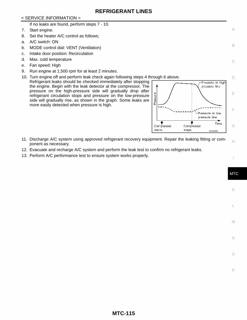
REFRIGERANT LINES
C
D
E
F
G
H
I
K
L
M
A
B
TC
N
O
P
< SERVICE INFORMATION >
M
If no leaks are found, perform steps 7 - 10.7. Start engine.8. Set the heater A/C control as follows;a. A/C switch: ONb. MODE control dial: VENT (Ventilation)c. Intake door position: Recirculationd. Max. cold temperaturee. Fan speed: High9. Run engine at 1,500 rpm for at least 2 minutes.10. Turn engine off and perform leak check again following steps 4 through 6 above.
Refrigerant leaks should be checked immediately after stoppingthe engine. Begin with the leak detector at the compressor. Thepressure on the high-pressure side will gradually drop afterrefrigerant circulation stops and pressure on the low-pressureside will gradually rise, as shown in the graph. Some leaks aremore easily detected when pressure is high.
11. Discharge A/C system using approved refrigerant recovery equipment. Repair the leaking fitting or com-ponent as necessary.
12. Evacuate and recharge A/C system and perform the leak test to confirm no refrigerant leaks.13. Perform A/C performance test to ensure system works properly.
SHA839E
MTC-115
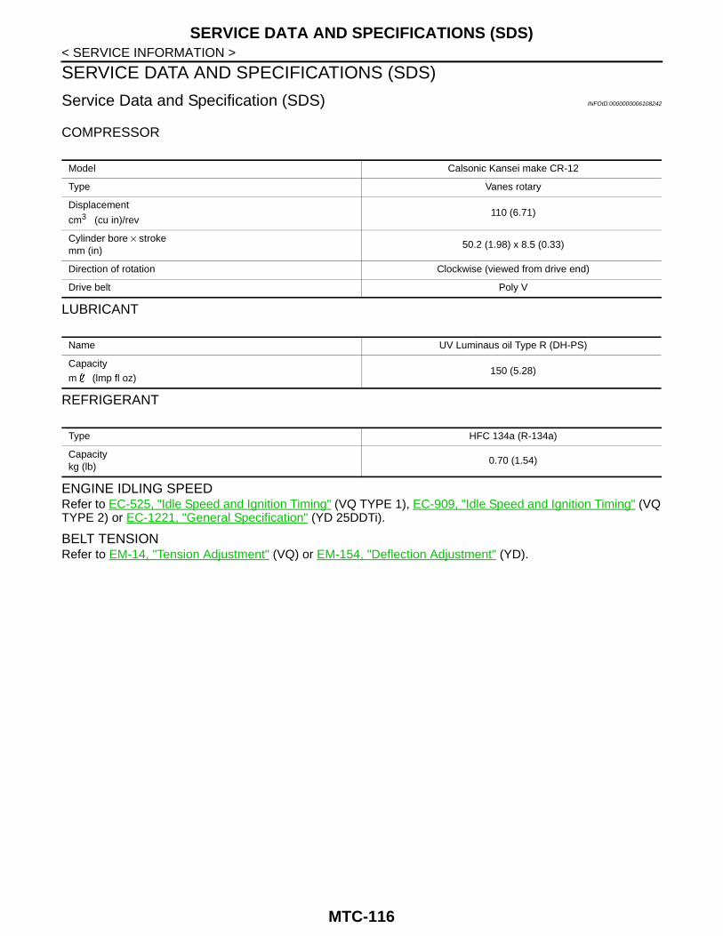
SERVICE DATA AND SPECIFICATIONS (SDS)
< SERVICE INFORMATION >SERVICE DATA AND SPECIFICATIONS (SDS)
Service Data and Specification (SDS) INFOID:0000000006108242
COMPRESSOR
LUBRICANT
REFRIGERANT
ENGINE IDLING SPEEDRefer to EC-525, "Idle Speed and Ignition Timing" (VQ TYPE 1), EC-909, "Idle Speed and Ignition Timing" (VQTYPE 2) or EC-1221, "General Specification" (YD 25DDTi).
BELT TENSIONRefer to EM-14, "Tension Adjustment" (VQ) or EM-154, "Deflection Adjustment" (YD).
Model Calsonic Kansei make CR-12
Type Vanes rotary
Displacement
cm3 (cu in)/rev110 (6.71)
Cylinder bore × strokemm (in)
50.2 (1.98) x 8.5 (0.33)
Direction of rotation Clockwise (viewed from drive end)
Drive belt Poly V
Name UV Luminaus oil Type R (DH-PS)
Capacity
m (lmp fl oz)150 (5.28)
Type HFC 134a (R-134a)
Capacitykg (lb)
0.70 (1.54)
MTC-116