air conditioner (split type) owner’s manual• the quali¿ ed service person is a person who...
TRANSCRIPT

AIR CONDITIONER (SPLIT TYPE)Owner’s Manual
Indoor UnitModel name:
4-way Cassette type
40TSV0131UP40TSV0181UP40TSV0241UP40TSV0361UP40TSV0401UP
1115350208
EnglishPortuguêsOwner’s Manual 1 English
Español 23
For commercial use
1115350208_EN-TH.indb Cover11115350208_EN-TH.indb Cover1 3/29/2559 BE 6:54 PM3/29/2559 BE 6:54 PM

– 1 –
Contents1 Precautions for safety . . . . . . . . . . . . . . . . . . . . . . . . . . . . . . . . . . . . . . . . . . . . . . . . . . 3
2 Part names . . . . . . . . . . . . . . . . . . . . . . . . . . . . . . . . . . . . . . . . . . . . . . . . . . . . . . . . . . . 5
3 Wireless remote controller . . . . . . . . . . . . . . . . . . . . . . . . . . . . . . . . . . . . . . . . . . . . . . 5
3-1.Parts name of remote controller . . . . . . . . . . . . . . . . . . . . . . . . . . . . . . . . . . . . . . . 5
3-2.Adjusting clock . . . . . . . . . . . . . . . . . . . . . . . . . . . . . . . . . . . . . . . . . . . . . . . . . . . . . 6
3-3.Handling the remote controller . . . . . . . . . . . . . . . . . . . . . . . . . . . . . . . . . . . . . . . . 7
3-4.Signal receiving unit. . . . . . . . . . . . . . . . . . . . . . . . . . . . . . . . . . . . . . . . . . . . . . . . . 7
3-5.How to use remote controller . . . . . . . . . . . . . . . . . . . . . . . . . . . . . . . . . . . . . . . . . 8
4 Wired remote controller. . . . . . . . . . . . . . . . . . . . . . . . . . . . . . . . . . . . . . . . . . . . . . . . 11
4-1.Display section . . . . . . . . . . . . . . . . . . . . . . . . . . . . . . . . . . . . . . . . . . . . . . . . . . . . 11
4-2.Operation section . . . . . . . . . . . . . . . . . . . . . . . . . . . . . . . . . . . . . . . . . . . . . . . . . . 12
4-3.Correct usage . . . . . . . . . . . . . . . . . . . . . . . . . . . . . . . . . . . . . . . . . . . . . . . . . . . . . 12
4-4.Timer operation. . . . . . . . . . . . . . . . . . . . . . . . . . . . . . . . . . . . . . . . . . . . . . . . . . . . 13
4-5.Power saving mode . . . . . . . . . . . . . . . . . . . . . . . . . . . . . . . . . . . . . . . . . . . . . . . . 13
5 Adjusting airflow direction . . . . . . . . . . . . . . . . . . . . . . . . . . . . . . . . . . . . . . . . . . . . . 14
6 Self clean mode . . . . . . . . . . . . . . . . . . . . . . . . . . . . . . . . . . . . . . . . . . . . . . . . . . . . . . 15
7 Operating air conditioner without remote controller (temporary operation) . . . . . 16
8 Wireless remote controller A-B selection . . . . . . . . . . . . . . . . . . . . . . . . . . . . . . . . . 16
9 Advanced settings . . . . . . . . . . . . . . . . . . . . . . . . . . . . . . . . . . . . . . . . . . . . . . . . . . . . 17
10 Maintenance . . . . . . . . . . . . . . . . . . . . . . . . . . . . . . . . . . . . . . . . . . . . . . . . . . . . . . . . . 19
11 Troubleshooting. . . . . . . . . . . . . . . . . . . . . . . . . . . . . . . . . . . . . . . . . . . . . . . . . . . . . . 20
12 Operations and performance . . . . . . . . . . . . . . . . . . . . . . . . . . . . . . . . . . . . . . . . . . . 21
13 Installation . . . . . . . . . . . . . . . . . . . . . . . . . . . . . . . . . . . . . . . . . . . . . . . . . . . . . . . . . . 22
Original instruction
ADOPTION OF NEW REFRIGERANTThis Air Conditioner uses R410A an environmentally friendly refrigerant.
According to IEC 60335-1This appliance is not intended for use by persons (including children) with reduced physical, sensory or mental capabilities, or lack of experience and knowledge, unless they have been given supervision or instruction concerning use of the appliance by a person responsible for their safety. Children should be supervised to ensure that they do not play with the appliance.
According to EN 60335-1This appliance can be used by children aged from 8 years and above and persons with reduced physical, sensory or mental capabilities or lack of experience and knowledge if they have been given supervision or instruction concerning use of the appliance in a safe way and understand the hazards involved.Children shall not play with the appliance. Cleaning and user maintenance shall not be made by children without supervision.
Auto-restart
This air conditioner is equipped with an Automatic restarting facility which allows the air conditioner to resume the set operating conditions in the event of a supply power shutdown without the use of the remote controller.
2-EN1-EN
1115350208_EN-TH.indb 11115350208_EN-TH.indb 1 3/29/2559 BE 6:54 PM3/29/2559 BE 6:54 PM

– 2 –
EN
TH
Warning indications on the air conditioner unit
Warning indication Description
WARNING
ELECTRICAL SHOCK HAZARDDisconnect all remote electric power supplies before servicing.
WARNING
ELECTRICAL SHOCK HAZARDDisconnect all remote electric power supplies before servicing.
WARNING
Moving parts.Do not operate unit with grille removed.Stop the unit before the servicing.
WARNING
Moving parts.Do not operate unit with grille removed.Stop the unit before the servicing.
CAUTION
High temperature parts.You might get burned when removing this panel.
CAUTION
High temperature parts.You might get burned when removing this panel.
CAUTION
Do not touch the aluminum fins of the unit.Doing so may result in injury.
CAUTION
Do not touch the aluminum fins of the unit.Doing so may result in injury.
CAUTION
BURST HAZARDOpen the service valves before the operation, otherwise there might be the burst.
CAUTION
BURST HAZARDOpen the service valves before the operation, otherwise there might be the burst.
Please read carefully through these instructions that contain important information which complies with the“Machinery” Directive (Directive 2006 / 42 / EC), and ensure that you understand them.After reading these instructions, be sure to keep them in a safe place together with the Installation Manual suppliedwith your product.
Generic Denomination: Air Conditioner
Definition of Qualified Installer or Qualified Service PersonThe air conditioner must be installed, maintained, repaired and removed by a qualified installer or qualified serviceperson. When any of these jobs is to be done, ask a qualified installer or qualified service person to do them for you.A qualified installer or qualified service person is an agent who has the qualifications and knowledge described inthe table below.
Agent Qualifications and knowledge which the agent must have
Qualified installer
• The quali ed installer is a person who installs, maintains, relocates and removes the air conditioners madeby Toshiba Carrier Corporation. He or she has been trained to install, maintain, relocate and remove the airconditioners made by Toshiba Carrier Corporation or, alternatively, he or she has been instructed in suchoperations by an individual or individuals who have been trained and is thus thoroughly acquainted with theknowledge related to these operations.
• The quali ed installer who is allowed to do the electrical work involved in installation, relocation and removalhas the quali cations pertaining to this electrical work as stipulated by the local laws and regulations, andhe or she is a person who has been trained in matters relating to electrical work on the air conditioners madeby Toshiba Carrier Corporation or, alternatively, he or she has been instructed in such matters by anindividual or individuals who have been trained and is thus thoroughly acquainted with the knowledgerelated to this work.
• The quali ed installer who is allowed to do the refrigerant handling and piping work involved in installation,relocation and removal has the quali cations pertaining to this refrigerant handling and piping work asstipulated by the local laws and regulations, and he or she is a person who has been trained in mattersrelating to refrigerant handling and piping work on the air conditioners made by Toshiba Carrier Corporationor, alternatively, he or she has been instructed in such matters by an individual or individuals who have beentrained and is thus thoroughly acquainted with the knowledge related to this work.
• The quali ed installer who is allowed to work at heights has been trained in matters relating to working atheights with the air conditioners made by Toshiba Carrier Corporation or, alternatively, he or she has beeninstructed in such matters by an individual or individuals who have been trained and is thus thoroughlyacquainted with the knowledge related to this work.
Qualified serviceperson
• The quali ed service person is a person who installs, repairs, maintains, relocates and removes the airconditioners made by Toshiba Carrier Corporation. He or she has been trained to install, repair, maintain,relocate and remove the air conditioners made by Toshiba Carrier Corporation or, alternatively, he or shehas been instructed in such operations by an individual or individuals who have been trained and is thusthoroughly acquainted with the knowledge related to these operations.
• The quali ed service person who is allowed to do the electrical work involved in installation, repair,relocation and removal has the quali cations pertaining to this electrical work as stipulated by the local lawsand regulations, and he or she is a person who has been trained in matters relating to electrical work on theair conditioners made by Toshiba Carrier Corporation or, alternatively, he or she has been instructed in suchmatters by an individual or individuals who have been trained and is thus thoroughly acquainted with theknowledge related to this work.
• The quali ed service person who is allowed to do the refrigerant handling and piping work involved ininstallation, repair, relocation and removal has the quali cations pertaining to this refrigerant handling andpiping work as stipulated by the local laws and regulations, and he or she is a person who has been trainedin matters relating to refrigerant handling and piping work on the air conditioners made by Toshiba CarrierCorporation or, alternatively, he or she has been instructed in such matters by an individual or individualswho have been trained and is thus thoroughly acquainted with the knowledge related to this work.
• The quali ed service person who is allowed to work at heights has been trained in matters relating toworking at heights with the air conditioners made by Toshiba Carrier Corporation or, alternatively, he or shehas been instructed in such matters by an individual or individuals who have been trained and is thusthoroughly acquainted with the knowledge related to this work.
4-EN3-EN
1115350208_EN-TH.indb 21115350208_EN-TH.indb 2 3/29/2559 BE 6:54 PM3/29/2559 BE 6:54 PM

– 3 –
1 Precautions for safetyThe manufacturer shall not assume any liability for the damage caused by not observing the description of this manual.
WARNING
General• Carefully read Owner’s Manual before starting the air conditioner. There are many important things to keep in mind
for daily operation.• Ask for installation to be performed by the dealer or a professional. Only a qualified installer is able to install an air
conditioner. If a non-qualified person installs an air conditioner, it may result in problems such as fire, electric shock, injury, water leakage, noise and vibration.
• Do not use any refrigerant different from the one specified for complement or replacement. Otherwise, abnormally high pressure may be generated in the refrigeration cycle, which may result in a failure or explosion of the product or an injury to your body.
• Places where the operation sound of the outdoor unit may cause a disturbance. (Especially at the boundary line with a neighbour, install the air conditioner while considering the noise.)
Transportation and storage• To transport the air conditioner, wear shoes with protective toe caps, protective gloves, and other protective clothing.• To transport the air conditioner, do not take hold of the bands around the packing carton. You may injure yourself if
the bands should break.• Before stacking the packing cartons for storage or transportation, heed the precautions written on the packing
cartons. Failure to heed the precautions may cause the stack to collapse.• The air conditioner must be transported in stable condition. If any part of the product broken, contact your dealer.• When the air conditioner must be transported by hand, carry it by two or more people.
Installation• Only a qualified installer or qualified service person is allowed to carry out the electrical work of the air conditioner.
Under no circumstances must this work be done by an unqualified individual since failure to carry out the work properly may result in electric shocks and/or electrical leaks.
• After the installation work has been completed, have the installer explain about the circuit breaker positions. In the event that trouble has occurred in the air conditioner, set the circuit breaker to the OFF position, and contact a service person.
• If the unit is installed in a small room, take appropriate measures to prevent the refrigerant from exceeding the limit concentration even if it leaks. Consult the dealer from whom you purchased the air conditioner when you implement the measures. Accumulation of highly concentrated refrigerant may cause an oxygen deficiency accident.
• Do not install the air conditioner in a location that may be subject to a risk of expire to a combustible gas. If a combustible gas leaks and becomes concentrated around the unit, a fire may occur.
• Use the company-specified products for the separately purchased parts. Use of non-specified products may result in fire, electric shock, water leakage or other trouble. Have the installation performed by a professional.
• Confirm that earthing is performed correctly.
Operation• Before opening the intake grille of the indoor unit or service panel of the outdoor unit, set the circuit breaker to the
OFF position. Failure to set the circuit breaker to the OFF position may result in electric shocks through contact with the interior parts. Only a qualified installer or qualified service person is allowed to remove the intake grille of the indoor unit or service panel of the outdoor unit and do the work required.
• Inside the air conditioner are high-voltage areas and rotating parts. Due to the danger of electric shocks or of your fingers or physical objects becoming trapped in the rotating parts, do not remove service panel of the outdoor unit. When work involving the removal of these parts is required, contact a qualified installer or a qualified service person.
• Do not move or repair any unit by yourself. Since there is high voltage inside the unit, you may get electric shock when removing the cover and main unit.
• Use of a stand more than 50 cm high to clean the filter of the indoor unit or to carry out other such jobs constitutes working at heights. Due to the danger of falling off the stand and injuring yourself while working at heights, this kind of work should not be done by unqualified individuals. When this kind of work must be carried out, do not do it yourself but ask a qualified installer or a qualified service person to do it for you.
• Do not touch the aluminum fin of the outdoor unit. You may injure yourself if you do so. If the fin must be touched, do not touch it yourself but contact a qualified installer or a qualified service person.
• Do not climb onto or place objects on top of the outdoor unit. You may fall or the objects may fall off of the outdoor unit and result in injury.
• Do not place any combustion appliance in a place where it is directly exposed to the wind of air conditioner, otherwise it may cause imperfect combustion.
• When the air conditioner is operated with a combustion appliance in the same place, ventilate the room sufficiently. Poor ventilation causes oxygen shortage.
• When the air conditioner is used in a closed room, sufficiently ventilate the room. Poor ventilation causes oxygen shortage.
• Do not expose your body to cool air directly for a long time and do not cool yourself excessively.Doing so may result in deteriorated physical condition and ill health.
• Do not insert your finger or a stick into the air intake or discharge.Doing so may result injury as the fan is rotating at high speed inside the unit.
• Consult the shop where you purchased the air conditioner if air conditioning (cooling) is not performed properly as a refrigerant leakage may be the cause. Confirm the repair details with a qualified service person when the repair includes additional charging of the refrigerant.
• Stop running the air conditioner and turn off the breaker before cleaning.Otherwise, injury may result as the fan is rotating at high speed inside the unit.
Repairs• If there is any kind of trouble (such as when an error display has appeared, there is a smell of burning, abnormal
sounds are heard, the air conditioner fails to cool or water is leaking) has occurred in the air conditioner, do not touch the air conditioner yourself but set the circuit breaker to the OFF position, and contact a qualified service person. Take steps to ensure that the power will not be turned on (by marking “out of service” near the circuit breaker, for instance) until qualified service person arrives. Continuing to use the air conditioner in the trouble status may cause mechanical problems to escalate or result in electric shocks or other trouble.
• If the fan grille is damaged, do not approach the outdoor unit but set the circuit breaker to the OFF position, and contact a qualified service person to have the repairs done. Do not set the circuit breaker to the ON position until the repairs are completed.
• If there is a danger of the indoor unit’s falling, do not approach the indoor unit but set the circuit breaker to the OFF position, and contact a qualified installer or a qualified service person to refit the unit. Do not set the circuit breaker to the ON position until the unit has been refitted.
• If there is a danger of the outdoor unit’s toppling over, do not approach the outdoor unit but set the circuit breaker to the OFF position, and contact a qualified installer or a qualified service person to have the improvements or refitting done. Do not set the circuit breaker to the ON position until the improvements or refitting is completed.
• Do not customize the unit. Doing so may result in fire, electric shock or other trouble.
Relocation• When the air conditioner is to be relocated, do not relocate it yourself but contact a qualified installer or a qualified
service person. Failure to relocate the air conditioner properly may result in electric shocks and/or a fire.
6-EN5-EN
1115350208_EN-TH.indb 31115350208_EN-TH.indb 3 3/29/2559 BE 6:54 PM3/29/2559 BE 6:54 PM
– 4 –
EN
TH
CAUTIONTo disconnect the appliance from the mains supply.
• This appliance must be connected to the mains by means of a switch with a contact separation of at least 3 mm.
The installation fuse (all types can be used) must be used for the power supply line of this air conditioner.
Installation• Certainly lay the drain hose for perfect draining. Improper drainage may cause flooding in the house and getting
furniture wet.• Connect the air conditioner to an exclusive power supply of the rated voltage, otherwise the unit may break down or
cause a fire.• Confirm that the outdoor unit are fixed on the base. Otherwise, falling down of the units or other accidents may occur.
Operation• Do not use this air conditioner for special purpose such as preserving food, precision instruments, art objects,
breeding animals, car, vessel.• Do not touch any switches with wet finger, otherwise you may get an electric shock.• If the air conditioner will not be used for a considerably long time, turn off the main switch or the circuit breaker, for
safety.• To make the air conditioner operate in its original performance, operate it within the range of the operating
temperature specified in the instructions. Otherwise it may cause a malfunction, or water leak from the unit.• Prevent any liquid from falling into the remote controller. Do not spill juice, water or any kind of liquid.• Do not wash the air conditioner. Doing so may result in electric shock.• Check whether the installation base and other equipment have become deteriorated after being used for a long time.
Leaving them such condition may result in the unit’s falling down and causing injury. • Do not leave flammable sprays or other flammable materials near the air conditioner, and do not spray flammable
aerosol directly to the air conditioner. They may catch fire.• Stop running the air conditioner and turn off the breaker before cleaning.
Otherwise, injury may result as the fan is rotating at high speed inside the unit.• Ask for cleaning of the air conditioner to be performed by the dealer.
Cleaning the air conditioner in an improper manner may cause damage to plastic parts, insulation failure of electric parts or other parts, and result in a malfunction. In the worst case, it may result in water leakage, electric shock, smoke emission or fire.
• Do not put a water container such as a vase on the unit.Water intrusion into the unit may occur and it may cause deterioration of electric insulation and result in electric shock.
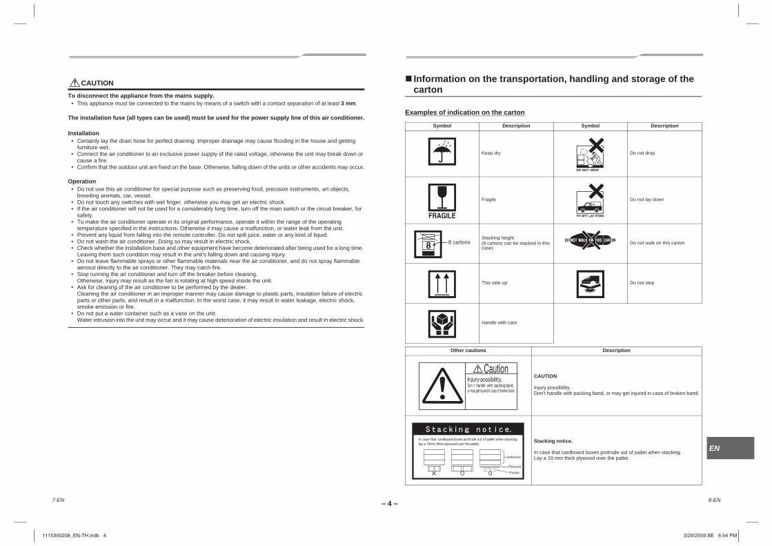
Information on the transportation, handling and storage of the carton
Examples of indication on the carton
noitpircseDlobmySnoitpircseDlobmyS
pord ton oDyrd peeK
nwod yal ton oDeligarF
Stacking height (9 cartons can be stacked in this case)
Do not walk on this carton
pets ton oDpu edis sihT
Handle with care
noitpircseDsnoituac rehtO
CAUTION
Injury possibility.Don’t handle with packing band, or may get injured in case of broken band.
Stacking notice.
In case that cardboard boxes protrude out of pallet when stacking.Lay a 10 mm thick plywood over the pallet.
8 cartons
8-EN7-EN
1115350208_EN-TH.indb 41115350208_EN-TH.indb 4 3/29/2559 BE 6:54 PM3/29/2559 BE 6:54 PM

– 5 –
2 Part names
Indoor unit
Outdoor unit (The design varies depending on the outdoor unit.The following illustration shows an example.)
KnobKnob to open/close the suction port.
Provided in the electric control box.
Earth screw
Air filterRemoves dust or trash.(Provided on the suction port.)
Change the direction of the air to be discharged according to cool mode.
Discharge louver of discharge port
The air in the room is sucked in from this port.
Suction air port
Projection of air filter
Signal receiving unit
Air intake(Side and rear)
PanelThere is an earth screw, valves, and electric parts inside.
Air discharge
Piping panel
Wiring hole
Refrigerant pipe outletFixing leg
3 Wireless remote controller3-1. Parts name of remote
controller
Wireless remote controller and its functions
1 Infrared signal emitterTransmits a signal to the indoor unit.
2 START/STOP buttonPress the button to start operation.(A receiving beep is heard.)Press the button again to stop operation.(A receiving beep is heard.)If no receiving sound is heard from the indoor unit, press the button twice.
3 Mode select button (MODE)Press this button to select a mode.Each time you press the button, a mode is selected in a sequence that goes from A: Auto changeover control, : Cool, : Dry, : Fan only, and back to A. (A receiving beep is heard.)
4 Temperature button ( )
5 Fan speed button (FAN)Press this button to select fan speed. When you select AUTO, the fan speed is automatically adjusted according to the room temperature.You can also manually select the desired fan speed from among five settings.(LOW , LOW+ , MED , MED+ , HIGH )Five patterns are displayed, but LOW+ is equal to LOW , and MED+ to MED
.When you select Dry, fan speed is automatically changed to AUTO and it is not manually adjustable.(A receiving beep is heard.)
6 Auto louver button (SWING)Press this button to swing the louver.(A receiving beep is heard.)Press the SWING button to stop the louver swinging.(A receiving beep is heard.)
7 Set louver button (FIX)Press this button to adjust the airflow direction.(A receiving beep is heard.) It cannot be operated by holding down the button. Push the button with some interval.
8 Off timer button (OFF)Press this button to set the OFF timer.
9 On timer button (ON)Press this button to set the ON timer.
10 Reserve button (SET)Press this button to reserve time settings.(A receiving beep is heard.)
11 Cancel button (CLR)Press this button to cancel ON timer and OFF timer. (A receiving beep is heard.)
12 High power button (Hi-POWER)Press this button to start the high power operation.Only available during Auto changeover control or Cool operation.This function is not operated group control.
...... The set temperature is increased up to 30 °C.
...... The set temperature is dropped down to 17 °C. (A receiving beep is heard.)
...... The temperature is not displayed during Fan only operation.
ON OFF
13
149
6
2
7
54
3
1211
810
1
10-EN9-EN
1115350208_EN-TH.indb 51115350208_EN-TH.indb 5 3/29/2559 BE 6:54 PM3/29/2559 BE 6:54 PM

– 6 –
EN
TH
13 PRESET buttonPress this button to change the operation mode to the preferred operation mode memorized previously. To memorize the operation mode, press this button for at least 3 seconds during the preferred operation mode. is displayed and the operation mode is memorized.
14 SLEEP buttonPress this button to start the OFF timer operation that automatically adjusts the room temperature and the fan speed.You can select the OFF timer time from four durations (1, 3, 5 or 9 hours).
Names and functions of indications on wireless remote controller
DisplayAll indications, except for clock time indication, are indicated by pressing the START/STOP button.
• In the illustration, all indications are indicated for explanation.During operation, only the relevant indications will be indicated on the remote controller.
1 Transmission markThis transmission mark ( ) indicates when the remote controller transmits signals to the indoor unit.
2 Mode displayIndicates the current operation mode.(A: Auto changeover control, : Cool, : Dry,
: Fan only)
3 Temperature displayIndicates the temperature setting (17 °C to 30 °C).When you set the operating mode to : Fan only, no temperature setting is indicated.
4 FAN speed displayIndicates the selected fan speed. AUTO or one of five fan speed levels (LOW , LOW+ , MED , MED+ , HIGH ) can be indicated.Indicates when the operating mode is : Dry.
5 TIMER and clock time displayThe time set for timer operation or clock time is indicated.The present time is always indicated except for TIMER operation.
6 Hi POWER displayIndicates when the high power operation starts.Press the Hi-POWER button to start and press it again to stop the operation.
7 (PRESET) displayIndicated when memorizing the preferred operation mode or when it has been memorized.Also, this icon is indicated when the memorized preferred operation is displayed.
8 Swing displayIndicated during the swinging operation where the horizontal louver automatically moves up and down.
Preparation and check before use
Loading batteries1 Remove the battery cover.
2 Insert 2 new batteries (R03 [AAA]) following the (+) and (–) positions.
Batteries• To replace the batteries, use two new batteries (R03
[AAA]).• In normal use, the batteries will last about one year.• Replace the batteries if there is no receiving beep
from the indoor unit or when the air conditioner cannot be operated using the remote controller.
• To avoid malfunctions by battery leakage, remove the batteries when not using the remote controller for more than one month.
3-2. Adjusting clock
Setting the clockBefore you start operating the air conditioner, set the clock of the remote controller using the procedures given in this section. The clock panel on the remote controller will indicate the time regardless of whether the air conditioner is in use or not.
Initial settingWhen batteries are inserted in the remote controller the clock panel will indicate AM 0:00 and will flash.
1 TIMER or buttonPress the TIMER or button to set the current time.Each press of the TIMER button changes the time in one minute steps.Pressing the TIMER button continually changes the time in ten minute steps.
2 SET buttonPress the SET button.The current time is indicated and the clock starts.
ACL
ON
ON
OFF
OFF
ON OFF 21
87546
1 23
12-EN11-EN
1115350208_EN-TH.indb 61115350208_EN-TH.indb 6 3/29/2559 BE 6:54 PM3/29/2559 BE 6:54 PM

– 7 –
Clock adjusting
1 CLOCK buttonPress the CLOCK by tip of a pencil.The CLOCK display flashes.
2 TIMER or buttonPress the TIMER or button to set the current time.Each press of the TIMER button changes the time by one minute.Pressing the TIMER button continually changes the time by ten minutes.
3 SET buttonPress the SET button.The current time is indicated and the clock starts.
3-3. Handling the remote controller
CAUTION• The air conditioner will not operate if curtains, doors or
other materials block the signals from the remote controller to the indoor unit.
• Prevent any liquid from falling into the remote controller.
• Do not expose the remote controller to direct sunlight or heat.
• If the infrared signal receiver on the indoor unit is exposed to direct sunlight, the air conditioner may not function properly.Use curtains to prevent the sunlight from reaching the receiver.
• If the room using the air conditioner has fluorescent lighting with electronic starters, signals may not be properly received. If you are planning to use such fluorescent lamps, consult your local dealer.
• If other electrical appliances react to the remote controller move these appliances or consult your local dealer.
Location of the remote controller
•
• When you select the timer operation, the remote controller automatically transmits a signal to the indoor unit at the specified time.If you keep the remote controller in a position that hinders proper signal transmission, a time lag of up to 15 minutes may occur.
Mounting the remote controller on the wall
When fixing the remote controller on the wall, insert the supplied remote controller mounting screw into the wall leaving a slight gap between the wall and the screw head, and hang the remote controller by inserting the screw head into the specified position on the back.
3-4. Signal receiving unitThe signal receiving unit is attached to the indoor unit.
1 Temporary operation button(See page 15)
2 Signal receiving partThe signal sent from the remote controller is received.
3 Display lampOne of displays flashed while an error occurs. When the display lamp flashes, refer to “Troubleshooting”.
4 lamp (Green)This lamp illuminates when unit is on.
5 lamp (Green)This lamp illuminates while the timer is reserved.
6 lamp (Orange)This lamp flashes during self clean operation and initial communication.
CAUTIONDisagreement in operation mode.
• If you use a wireless remote controller of another Toshiba air-conditioner and attempt to operate a function incompatible with this model, only a reception sound is heard and the function is not performed. (There is a case that the and lamps blink alternately to inform you of the above.)
Wall
Back of the remote controller
Remote controllermounting screw
1
2
3
456
The standard distance for signal reception is approximately 8 m vertically against the signal receiving unit. The distance becomes shorter when the angle is oblique against the signal receiving unit.The distance differs a little according to the capacity of the battery or other factor.
• Keep 1 m or more from the devices such as television, stereo, etc.(Disturbance of image or noise may generate.)
• To prevent a malfunction, select a place where is not influenced by a fluorescent light or direct sunlight.
• Two or more (Up to 6 units) indoor units with wireless type remote controller can be installed in the same room.
8 m
Signal receiving unit
90°
ON OFF
3
2
1
OFF
OFFON
ON
14-EN13-EN
1115350208_EN-TH.indb 71115350208_EN-TH.indb 7 3/29/2559 BE 6:54 PM3/29/2559 BE 6:54 PM

– 8 –
EN
TH
START/STOP button ( )
3-5. How to use remote controller
Cooling / fan only operation
Start
1Press this button to start the air conditioner.
2 Mode select button (MODE)Select Cool , or Fan only .
3 Temperature button ( )Set the desired temperature.When the air conditioner is in FAN ONLY operation, the temperature display is not indicated.
4 Fan speed button (FAN)Select one of LOW , LOW+ , MED , MED+ , HIGH .
• The OPERATION lamp (green) on the signal receiving unit goes on. And operation starts after approximately 3 minutes.(If you select FAN ONLY mode, the unit will start immediately.)
• The : Fan only mode does not control temperature.
StopSTART/STOP button ( )Press this button again to stop the air conditioner.In the Cool, Dry, or Auto (cooling) mode, the fan runs for 10 minutes (or more) for self clean operation.
Dry operation
Start
1 START/STOP button ( )Press this button to start the air conditioner.
2 Mode select button (MODE)Select DRY .
3 Temperature button ( )Set the desired temperature.
• The fan speed display indicates • The OPERATION lamp (green) on the signal
receiving unit lights, and operation starts after approximately 3 minutes.
StopSTART/STOP button ( )Press this button again to stop the air conditioner.In the Cool, Dry, or Auto (cooling) mode, the fan runs for 10 minutes (or more) for self clean operation.
Automatic operation (auto changeover)
Start
1 START/STOP button ( )Press this button to start the air conditioner.
2 Mode select button (MODE)Select A.
3 Temperature button ( )Set the desired temperature.
4 Fan speed button (FAN)Select one of LOW , LOW+ , MED , MED+ , HIGH .
• The OPERATION lamp (green) on the signal receiving unit lights.The operating mode is selected in accordance with the room temperature and operation starts after approximately 3 minutes.
• If the “A” mode is uncomfortable, you can select the desired conditions manually.
StopSTART/STOP button ( )Press this button again to stop the air conditioner.In the Cool, Dry, or Auto (cooling) mode, the fan runs for 10 minutes (or more) for self clean operation.
2
43
1 2
31
2
3
14
16-EN15-EN
1115350208_EN-TH.indb 81115350208_EN-TH.indb 8 3/29/2559 BE 6:54 PM3/29/2559 BE 6:54 PM
– 9 –
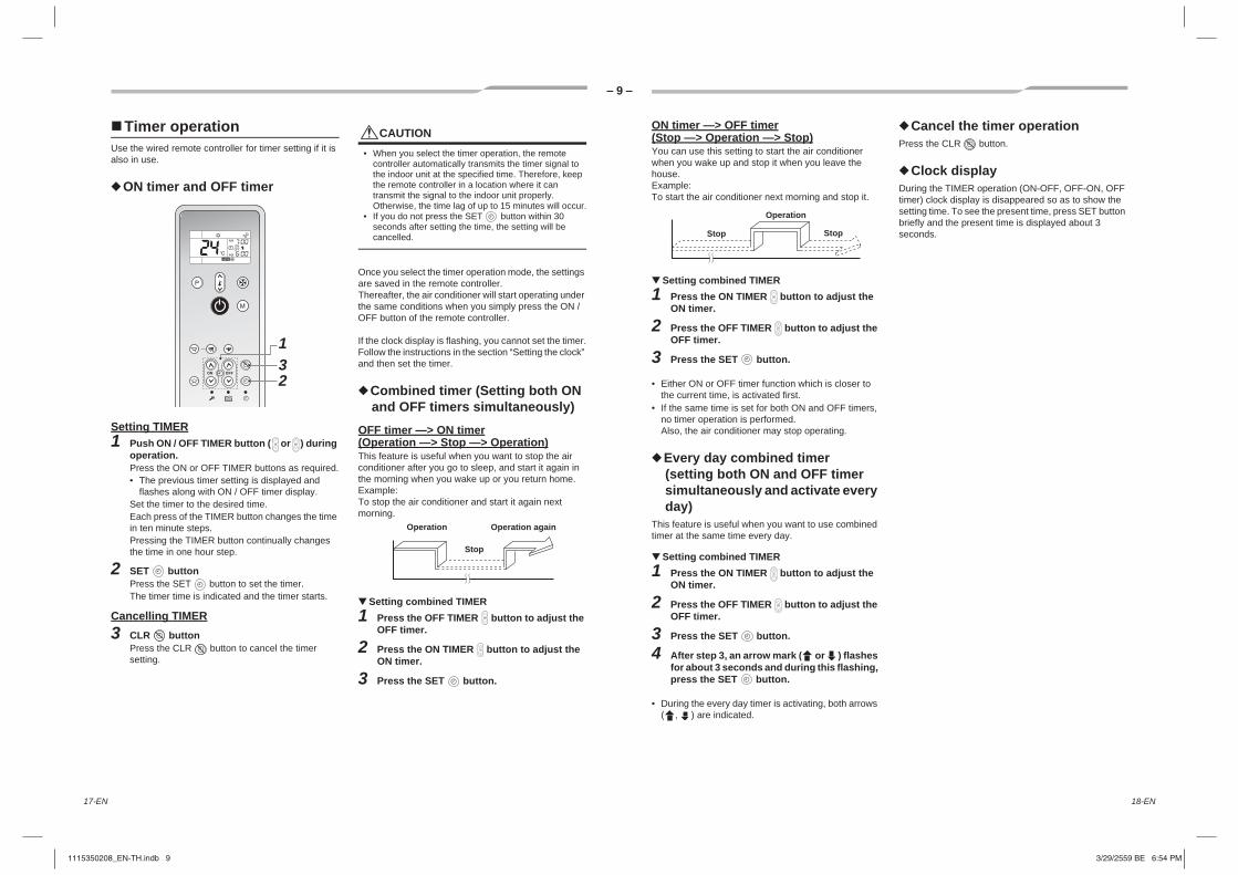
Timer operationUse the wired remote controller for timer setting if it is also in use.
ON timer and OFF timer
Setting TIMER1 Push ON / OFF TIMER button ( or ) during
operation.Press the ON or OFF TIMER buttons as required.• The previous timer setting is displayed and
flashes along with ON / OFF timer display.Set the timer to the desired time.Each press of the TIMER button changes the time in ten minute steps.Pressing the TIMER button continually changes the time in one hour step.
2 SET buttonPress the SET button to set the timer.The timer time is indicated and the timer starts.
Cancelling TIMER3 CLR button
Press the CLR button to cancel the timer setting.
CAUTION• When you select the timer operation, the remote
controller automatically transmits the timer signal to the indoor unit at the specified time. Therefore, keep the remote controller in a location where it can transmit the signal to the indoor unit properly. Otherwise, the time lag of up to 15 minutes will occur.
• If you do not press the SET button within 30 seconds after setting the time, the setting will be cancelled.
Once you select the timer operation mode, the settings are saved in the remote controller.Thereafter, the air conditioner will start operating under the same conditions when you simply press the ON / OFF button of the remote controller.
If the clock display is flashing, you cannot set the timer.Follow the instructions in the section “Setting the clock” and then set the timer.
Combined timer (Setting both ON and OFF timers simultaneously)
OFF timer —> ON timer(Operation —> Stop —> Operation)This feature is useful when you want to stop the air conditioner after you go to sleep, and start it again in the morning when you wake up or you return home.Example:To stop the air conditioner and start it again next morning.
Setting combined TIMER1 Press the OFF TIMER button to adjust the
OFF timer.
2 Press the ON TIMER button to adjust the ON timer.
3 Press the SET button.
Operation Operation again
Stop
ON timer —> OFF timer(Stop —> Operation —> Stop)You can use this setting to start the air conditioner when you wake up and stop it when you leave the house.Example:To start the air conditioner next morning and stop it.
Setting combined TIMER1 Press the ON TIMER button to adjust the
ON timer.
2 Press the OFF TIMER button to adjust the OFF timer.
3 Press the SET button.
• Either ON or OFF timer function which is closer to the current time, is activated first.
• If the same time is set for both ON and OFF timers, no timer operation is performed.Also, the air conditioner may stop operating.
Every day combined timer(setting both ON and OFF timer simultaneously and activate every day)
This feature is useful when you want to use combined timer at the same time every day.
Setting combined TIMER1 Press the ON TIMER button to adjust the
ON timer.
2 Press the OFF TIMER button to adjust the OFF timer.
3 Press the SET button.
4 After step 3, an arrow mark ( or ) flashes for about 3 seconds and during this flashing, press the SET button.
• During the every day timer is activating, both arrows ( , ) are indicated.
Cancel the timer operationPress the CLR button.
Clock displayDuring the TIMER operation (ON-OFF, OFF-ON, OFF timer) clock display is disappeared so as to show the setting time. To see the present time, press SET button briefly and the present time is displayed about 3 seconds.
Operation
StopStop
ON OFF
ON
ON
ON
231
OFF
OFF
OFF
ON
OFF
18-EN17-EN
1115350208_EN-TH.indb 91115350208_EN-TH.indb 9 3/29/2559 BE 6:54 PM3/29/2559 BE 6:54 PM

– 10 –
EN
TH
ON OFF
High power operation
High power (Hi POWER)The Hi POWER (high power operation) mode automatically controls room temperature, fan speed and operation mode so that the room is quickly cooled.
Setting Hi POWER mode1 Hi-POWER button
Press the Hi-POWER button after starting any operation. At the same time, the “Hi POWER” mark on the remote controller is indicated.
Cancelling Hi POWER mode1 Hi-POWER button
Press the Hi-POWER button once again.At the same time, the “Hi POWER” mark on the remote controller goes out.
CAUTION• The Hi POWER mode cannot be activated in the DRY
and FAN ONLY operation and when the ON TIMER operation is reserved.
• Hi POWER mode is not available for group control.When Hi POWER is transmitted to the Header indoor unit, the receiving sound is heard but the Hi POWER mode will not be performed. Please cancel the Hi POWER mode.
Preset operationSet your preferred operation mode for future use.The setting is memorized by the unit for future operation (except airflow direction).
Select your preferred operation.
1 Press the PRESET button for 3 seconds to memorize the setting.The mark is displayed.
When you press this button next time, the memorized operation mode will be enabled.
Sleep timer operationTo start the sleep timer (OFF timer) operation.
1 Press the SLEEP button.Select 1, 3, 5 or 9 hours for the OFF timer operation.
11
1
20-EN19-EN
1115350208_EN-TH.indb 101115350208_EN-TH.indb 10 3/29/2559 BE 6:54 PM3/29/2559 BE 6:54 PM

– 11 –
4 Wired remote controllerThis remote controller can control the operation of up to 8 indoor units.
4-1. Display sectionIn the display illustration below all the icons are shown. When the unit is in operation, only relevant icons will be displayed. • When the leak breaker is turned on for the first time, flashes on the display
part of the remote controller. • While this icon is flashing, the model is being automatically confirmed.
Wait till icon has disappeared to use the remote controller.
1 Operation modeThe selected operation mode is displayed.
2 Error displayDisplayed while the protective device works or a error occurs.
3 SETTING displayDisplayed during setup of the timer or other settings.
4 TEST run displayDisplayed during a test run.
5 Timer displayWhen an error occurs, error code is displayed.
6 Timer mode displayThe selected timer mode is displayed.
7 Louver position displayDisplays louver position.
8 Swing displayDisplayed during up / down movement of the louver.
9 Filter displayReminder to clean the air filter.
10 Fan speed displayThe selected fan speed mode is displayed.
11 Set temperature displayThe selected set temperature is displayed.
12 Power saving mode displayLimits compressor speed (capacity) to save energy.
SET
TIME
TIMER SET
TESTFILTERRESET
TEMP.
CL
FAN
SAVE
SWING/FIX
VENT
MODE
ON / OFF
UNIT LOUVER
Display section
Operation section
1
62
59
10
4 123
11
87
(Auto)(High)(Med.)(Low)
13 UNIT No. displayDisplays the number of the indoor unit selected.Also displays error code of indoor and outdoor units.
14 Remote controller sensor displayDisplayed while the sensor of the remote controller is used.
15 No function displayDisplayed when the function requested is not available on that model.
16 Self clean operation displayDisplayed during self clean operation to dry the indoor heat exchanger.
17 Service display
18 Operation ready displayThis display appears on some models.
19 Louver Number display. (exapmle:01, 02, 03, 04)
20 Louver lock displayDisplayed when there is a louver-locked unit in the group (including 1 indoor unit by 1 outdoor unit).
14
15
13
18
16
1719 20
22-EN21-EN
1115350208_EN-TH.indb 111115350208_EN-TH.indb 11 3/29/2559 BE 6:54 PM3/29/2559 BE 6:54 PM

– 12 –
EN
TH
4-2. Operation sectionPush each button to select a desired operation.• The control saves commands in memory and after the initial setting, there is no need for any additional
settings unless changes are desired. The air conditioner can be operated by pushing the button.
1 button (Temperature set button)Adjusts the set point.Select the desired set point by pushing TEMP. or TEMP. .
2 button (Timer set button)Use to setup the timer.
3 button (Filter reset button)Resets “ ” display after cleaning filter.
4 button (Test button)Use only for service. (During normal operation, do not use this button.)
5 buttonWhen the button is pushed, the operation starts, and it stops by pushing the button again.When the operation has stopped, the operation lamp and all the displays disappear.
6 Operation lampGreen light illuminates when unit is on.Although it flashes when operating the protection device or an error occurs.
7 button (Operation mode button)Selects desired operation mode.
8 button (Fan speed button)Selects the desired Fan speed.
9 button (Ventilation button)Not available.• “ ” is displayed on the remote controller when this
button is pushed.
10 button (Power save operation)Use to initiate power saving mode.
11 button (Unit / Louver select button)Selects a unit number (left) and louver number (right).UNIT: Selects an indoor unit when adjusting wind direction multiple indoor units are controlled with one remote controller.LOUVER: Selects a louver when setting wind direction adjustment independently.
12 button (Swing / Louver direction button)Selects automatic swing or setting the louver direction.
OPTION:Remote controller sensorUsually the temperature sensor of the indoor unit senses the temperature. The temperature on the surrounding of the remote controller can also be sensed.For details, contact the dealer from which you have purchased the air conditioner.
86
43
25 7
10
12
1
9 11
4-3. Correct usageWhen the air conditioner is used for the first time or when the setting is changed, follow the steps below. Settings are saved in memory and are displayed anytime the unit is turned on by pushing the button.
Preparation• When the circuit breaker is turned on, the partition lines are displayed on the remote controller.* After the circuit breaker is turned on, the remote controller does not accept any commands for approx.
1 minute, this is not a failure.
REQUIREMENTWhen the air conditioner is re-powered after it has not been used for a long period, turn on the circuit breaker at least 12 hours before starting the air conditioner.
Start1 Push button.
The operation lamp illuminates, and the operation starts.
2 Select an operation mode with the “ ” button.One push of the button, and the display changes in the order shown below.
3 Select fan speed with “ ” button.One push of the button, and the display changes in the order shown below.
• When fan is in “ Auto”, fan speed is adjusted based on difference between set point and room temperature.
• The temperature sensor detects the return air temperature at the indoor unit, which differs from the room temperature depending on the installation condition.Set point is a target of room temperature. ( “Auto” is not selectable in the Fan mode.)
4 Select the set point temperature by pushing the “TEMP. ” or “TEMP. ” buttons.
StopPush button.The operation lamp goes off, and the operation stops.In the Cool, Dry, or Auto (cooling) mode, the fan runs for 10 minutes (or more) for self clean operation.
NOTE
Auto Changeover• When in Auto Mode, the unit selects the operating mode (cooling or fan only) based on the user set point temperature.• If the Auto mode is uncomfortable, you can select the desired conditions manually.
Cooling• If there is a demand for cooling, unit will start approximately 1 minute after mode is selected.
When restarting the operation after stopWhen the unit is attempted to restart immediately after it was stopped, the unit can not start for approx. 3 minutes this is to protect the compressor.
SET
TIME
TIMER SET
TESTFILTERRESET
TEMP.
CL
FAN
SAVE
SWING/FIX
VENT
MODE
ON / OFF
UNIT LOUVER
1 3 2
4
naFyrDotuA Cool
Auto High Med. Low
24-EN23-EN
1115350208_EN-TH.indb 121115350208_EN-TH.indb 12 3/29/2559 BE 6:54 PM3/29/2559 BE 6:54 PM

– 13 –
4-4. Timer operation• Three timer modes are available: (Setting of up to 168 hours is enabled.)
Set1 Push button.
The timer mode changes with every push of the button.
• and timer display flashes.
2 Push to select “set time”.• With every push of button, the set time increases
by 0.5 hr (30 minutes).When setting a time more than 24 hours for timer operation, timer can be set in increments of 1 hr. The maximum set time is 168 hr (7 days).The remote control displays the set time with time (between 0.5 and 23.5 hours) (*1) or number of days and time (24 hours or more) (*2) as shown below.
• With every push of button, the set time decreases by 0.5 hr (30 minutes) (0.5 - 23.5 hours) or 1 hr (24 - 168 hours).
Example of remote control display• 23.5 hours (*1)
• 34 hours (*2)
3 Push button.• icon disappears and time display goes on,
and or icon flashes.(When On timer is activated, time and On timer
are icons and other icons disappear.)
4 Cancel timer operationPush button.Timer icon disappears.
NOTE• When the operation stops after the timer reached the
preset time, the Repeat Off timer resumes the operation by pushing button and stops the operation after the time of the timer has reached the set time.
• When is pushed while the Off timer function of the air conditioner is active, the indication of the timer function disappears and then appears again after about 5 seconds.This is due to normal processing of the remote controller.
Off timer : The unit stops when the set time is reached.
Repeat Off timer : The unit stops daily when the set time is reached.
On timer : The unit starts when the set time is reached.
1
32 4
shows 1 day (24 hours).
shows 10 hours. (Total 34 hours)
)remit nO()remit ffO( (Repeat Off timer)
No display
Off Off On
Number of days Time
4-5. Power saving modeCase with wired remote controllerThe power saving mode saves energy by limiting the maximum current which will effect cooling capacity that the unit can generate.
Push button during operation.• The air conditioner enters power saving mode.• appears on the display.
Power saving mode will stay in effect until it is cancelled.To cancel the power saving mode, push button again.• disappears.
To configure the power saving mode settings
1 Push button for at least four seconds when the air conditioner is not working.• , symbol, and numbers flash.
2 Push (left side of the button) to select an indoor unit to be set.• Each time the button is pushed, UNIT No. change as follows:
3 Push TIME buttons, to adjust the power saving mode setting.• Each push of the button changes the power level by
1 % within the range from 100 % to 50 %.• The factory default is 75 %.
4 Push button.
5 Push button to complete the setting.
NOTE• When other electric appliances are used at the same time, to avoid triggering the circuit breaker, power saving mode is
recommended. Of course power saving mode can be used to save energy as well.• Power saving mode consumes less energy, but may not cool the room as much as normal mode. (The maximum current is
limited to approximately 75 % (factory default) of the normal mode.)• Even when operation start / stop, operation mode change, or power reset is performed during the power saving mode, the
power saving mode is retained until the next operation.
4
31
5 2
UNIT No. 1-1
UNIT No. 1-2
UNIT No. 1-3
UNIT No. 1-4
The fan of the selected unit runs.
Setting of power level in power saving mode
26-EN25-EN
1115350208_EN-TH.indb 131115350208_EN-TH.indb 13 3/29/2559 BE 6:54 PM3/29/2559 BE 6:54 PM

– 14 –
EN
TH
5 Adjusting airflow directionFor best cooling, adjust the louvers (adjustment plates of up/down wind direction) appropriately. Cold air descends, so to, and to cool a room tilt them horizontally.
• When the air conditioner is not working, the louvers are directed horizontally automatically.
Wireless remote controllerTo set the airflow direction
1 FIX button• The louver angle does not change immediately
after the FIX button is pushed. Check the louver status, and push FIX button after a while.
• In subsequent operations, the vertical airflow is automatically set in the direction to which you adjusted the louver using the FIX button.
To automatically swing the airflow directionPerform this function when the air conditioner is in operation.
1 SWING buttonPress the SWING button on the remote controller.• To stop the function, press the SWING button.
CAUTION• The FIX and SWING buttons will be disabled when the
air conditioner is not in operation (including when the ON timer is set).
• The louver angle does not change if the FIX button is pushed during SWING operation. Stop the SWING operation before changing the louver angle.
• Do not operate the air conditioner for long hours with the airflow direction set downward during the cooling or dry operation.Otherwise, condensation may occur on the surface of the vertical airflow louver and cause dew dripping.
• Do not move the vertical airflow louver manually. Always use the FIX button.If you move the louver manually, it may malfunction during operation.If the louver malfunctions, stop the air conditioner once, and restart.
• When the air conditioner is started immediately after it was stopped, the vertical airflow louver might not move for 10 seconds or so.
• Louver operation is limited when performing group control.
For cooling (COOL)Direct the louvers horizontally.
Wired remote controller
How to set up the louver direction1 Push during operation.
The louver direction changes for every push of the button.
In COOL / DRY operationDirect the louver (adjustment plate of up / down wind direction) horizontally. If directing it downward, the dew may form on the surface of the air discharge port and may drop down.
In FAN operationSelect a desired louver direction.
How to start swinging1 Push , set the louver (adjustment plate
of up / down wind direction) direction to the lowest position, and then push again.SWING is displayed and the up / down louver direction is automatically selected.
Display during swinging
How to stop swinging1 Push at a desired position while the
louver is swinging.• When is pushed after that, wind
direction can be set again from the highest position.
Display when swinging is stopped
In this case, push again two seconds later.• In Cool / Dry operation, the louver does not stop
as it directs downward. If stopping the louver as it directs downward during swing operation, it stops after moving to the third position from the highest position.
Display when stopping the swing
Unit select button• When multiple indoor units are controlled with one
remote controller, louver direction can be set for each indoor unit by selecting individually.
• To set louver direction individually, push button to display an indoor unit number in the control group. Then set the wind direction of the displayed indoor unit.
• When no indoor unit number is displayed, all indoor units in the control group can be controlled simultaneously.
• Each time button is pushed, the display changes as follows:
1 Unit select button
Initial setup
Initial setup
Repeat
* However, even if is pushed while the louver is swinging, the louver position is displayed as follows and highest position of the louver may not be selected.
Fan operation Cool / Dryoperation
Fan operationCool / Dryoperation
Not display
UNIT No. 1-1
UNIT No. 1-2
UNIT No. 1-3
UNIT No. 1-4
1
1
28-EN27-EN
1115350208_EN-TH.indb 141115350208_EN-TH.indb 14 3/29/2559 BE 6:54 PM3/29/2559 BE 6:54 PM

– 15 –
How to set louver wind direction individually
1 Select an indoor unit to be set by pushing (left side of the button) during
operation.• The indoor unit number changes each time you
push the button.
* When no unit number is displayed, all indoor units are selected.
2 Select a louver you want to adjust change by pushing (right side of the button).• Each time you push the button, the display on
the left of the remote controller changes as follows:
* When no louver number is displayed, all four louvers are selected.
3 Determine wind direction of the selected louver by pushing .• Each time you push the button, the display
changes as follows:
* During COOL (DRY) mode, (4) and (5) are not displayed.
Not display
Unit No. 1-1
Unit No. 1-2
Unit No. 1-3
Unit No. 1-4
Not display
Louver No.
03
01
0204
Refrigerant pipe
Drain pipe
Electrical control box
(1) (2) (3) (4)
(7) (6) (5)
6 Self clean modeThis function is provided to dry the inside of the indoor unit by the FAN operation after running the cooling / dry / AUTO (cooling) mode to keep the indoor unit clean.• The self clean time varies with the cooling / dry / Auto (cooling) operation time as follows.
• “ ” is displayed on the remote controller during self clean operation.• The operation lamp (Orange) lights and (Green) does not light on the signal receiving unit during self clean
operation.
To stop self clean forcibly, press START/STOP button twice in succession.
CAUTION• The fan continues to run even after START/STOP button is pushed to stop operation in some modes.
This is normal because the self clean mode is in progress.• The louvers open slightly and are directed horizontally during self clean, and they close when the self clean is
completed.• The self clean mode (function) cannot clean the room or remove the already existing mold and dust inside the indoor
unit.• To cancel the self clean function, consult the dealer.
Cooling / dry / Auto (cooling) emit naelc flesemit noitarepo
noitarepo naelc fles oNsetunim 01 naht sseL
ruoh1ruoh 1 naht ssel ot setunim 01
sruoh2ruoh 1 naht eroM
30-EN29-EN
1115350208_EN-TH.indb 151115350208_EN-TH.indb 15 3/29/2559 BE 6:54 PM3/29/2559 BE 6:54 PM
– 16 –
EN
TH
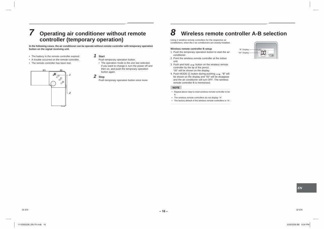
7 Operating air conditioner without remote controller (temporary operation)
In the following cases, the air conditioner can be operate without remote controller with temporary operation button on the signal receiving unit.
• The battery in the remote controller expired.• A trouble occurred on the remote controller.• The remote controller has been lost.
1 StartPush temporary operation button.• The operation mode is the one last selected.
If you want to change it, turn the power off and then on, and push the temporary operation button again.
2 StopPush temporary operation button once more.
1
2
8 Wireless remote controller A-B selectionUsing 2 wireless remote controllers for the respective air conditioners, when the 2 air conditioners are closely installed.
Wireless remote controller B setup1. Push the temporary operation button to start the air
conditioner.2. Point the wireless remote controller at the indoor
unit.3. Push and hold button on the wireless remote
controller by the tip of the pencil.“00” will be shown on the display.
4. Push MODE button during pushing . “B” will be shown on the display and “00” will be disappear and the air conditioner will turn OFF. The wireless remote controller B is memorized.
NOTE• Repeat above step to reset wireless remote controller to be
A.• The wireless remote controllers do not display “A”.• The factory default of the wireless remote controllers is “A”.
CHK
CHK
“B” Display“00” Display
32-EN31-EN
1115350208_EN-TH.indb 161115350208_EN-TH.indb 16 3/29/2559 BE 6:54 PM3/29/2559 BE 6:54 PM

– 17 –
9 Advanced settingsCase with wired remote controller
How to set up swing type
1 Push for at least four seconds when the air conditioner is not working.• , symbol, and numbers flash.
2 Select an indoor unit to be set by pushing (left side of the button).
• Each time you push the button, unit numbers change as follows:
The fan of the selected unit runs and the louvers start swinging.
3 Select a swing type by pushing TIME buttons.
CAUTIONDo not set the swing setup code to “0000”.(This setting may cause a failure of the louvers.)
4 Push the button.
5 Push the button to finish the setting.
2145
3
Swing setup code Swing of louvers
0001 Standard swing(Factory default)
gniws lauD2000
gniws elcyC3000
Not display
Unit No.1-1
Unit No.1-2
Unit No. 1-3
Unit No. 1-4
Swing setup code
Standard swingAll four louvers swing simultaneously at the same angle.
Dual swingAdjoining louver alternately swing horizontally and downward.
Cyclic swing (Recommended for cooling)All four louvers swing at different times like waves.
Swing
Horizontal
DownwardDownward
Horizontal
DownwardDownward
Horizontal
Horizontal
34-EN33-EN
1115350208_EN-TH.indb 171115350208_EN-TH.indb 17 3/29/2559 BE 6:54 PM3/29/2559 BE 6:54 PM

– 18 –
EN
TH
Setting the louver lock1 Push and hold the button (right side of
the button) for at least 4 seconds while running is stopped.
blinks.
• When no unit number is displayed, all units are selected.
2 Push the button (left side of the button) to select a unit.The unit number changes each time you push the button.
The fan of the selected unit runs, and the louver swings.
3 Push the “TEMP. ” buttons to display the number of the louver to fix its direction.The selected louver swings.
4 Push the buttons to select the direction of the louver you do not want to swing.
* If (4) or (5) is selected, condensation may occur during cooling.
5 Push the button to confirm the setting.When the setting is confirmed, the mark lights up.(To set the louver lock of another unit, repeat from Step 2. To set another louver lock of the same unit, repeat from Step 3.)
6 Push the button to finish the setting.
* F1 appears in the CODE No. section on the remote controller. This indicates that the louver 01 shown in the following figure is selected.
NOTEEven in louver lock mode, the louver temporarily moves in the following cases:• When the air conditioner is stopped
UNIT LOUVER
Unit No. 1-1
Unit No. 1-2
Unit No. 1-3
Unit No. 1-4
(1)0001
(2)0002
(3)0003
(5)0005
(4)0004
0001 - 0005 (Louver position code)
Louver No.
03
01
0204
Refrigerant pipe
Drain pipe
Electrical control box
Releasing the louver lockSet “0000” in Step 4 of “Setting the louver lock”.The mark disappears.
* Steps 1 - 3 and 5, 6 of “Setting the louver lock” also apply to releasing the lock.
Adjusting the horizontal direction1 Push and hold the and “TEMP. ”
buttons for at least 4 seconds while running is stopped.
blinks.“01” appears in CODE No.
2 Push the button (left side of the button) to select a unitThe unit number changes each time you push the button.
The fan of the selected unit runs, and the louver swings.
3 Push the “TEMP. ” buttons to change the CODE No. to “45”.
4 Push the “TIME ”buttons to select a direction.
5 Push the button to check the settings.The indicator stops blinking and stays lit, and the settings are confirmed.
6 Push button to finish the setting.* If the cold draft position is selected, the ceiling
smudging reduction effect will be reduced.
Direction SET DATA Direction setting
“0000” Smudging reduction position(reduces ceiling smudging)
“0002”
Cold draft position(Less directly expose your body to
cool air)(factory default)
0000SET DATA
Unit No. 1-1
Unit No. 1-2
Unit No. 1-3
Unit No. 1-4
No display
36-EN35-EN
1115350208_EN-TH.indb 181115350208_EN-TH.indb 18 3/29/2559 BE 6:54 PM3/29/2559 BE 6:54 PM
– 19 –
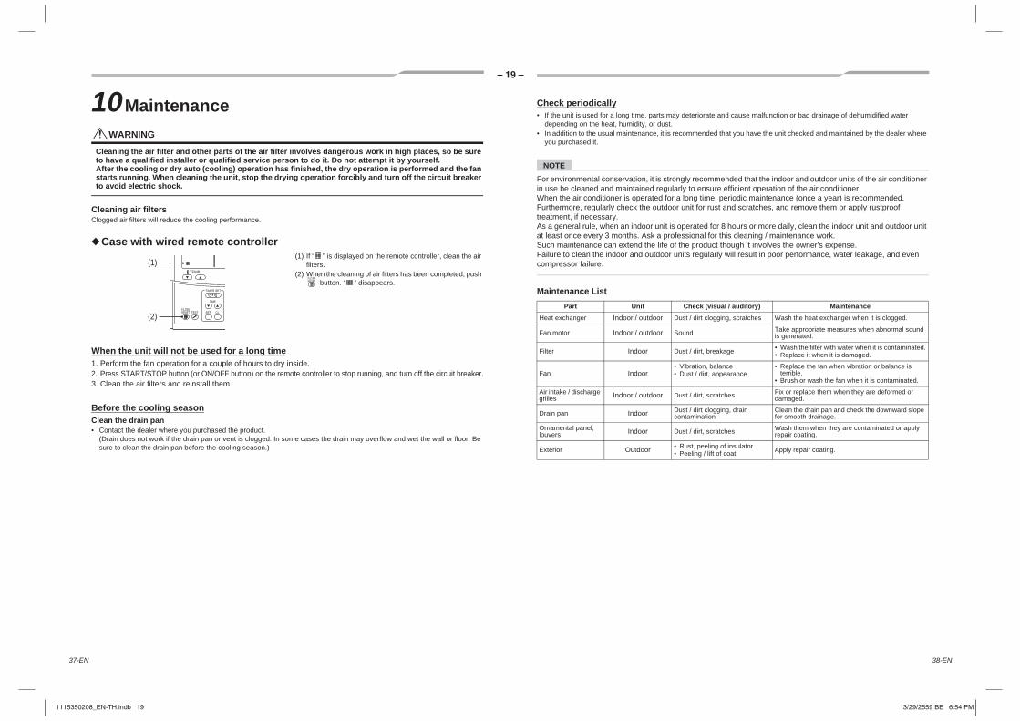
10MaintenanceWARNING
Cleaning the air filter and other parts of the air filter involves dangerous work in high places, so be sure to have a qualified installer or qualified service person to do it. Do not attempt it by yourself.After the cooling or dry auto (cooling) operation has finished, the dry operation is performed and the fan starts running. When cleaning the unit, stop the drying operation forcibly and turn off the circuit breaker to avoid electric shock.
Cleaning air filtersClogged air filters will reduce the cooling performance.
Case with wired remote controller(1) If “ ” is displayed on the remote controller, clean the air
filters.(2) When the cleaning of air filters has been completed, push
button. “ ” disappears.
When the unit will not be used for a long time1. Perform the fan operation for a couple of hours to dry inside.2. Press START/STOP button (or ON/OFF button) on the remote controller to stop running, and turn off the circuit breaker.3. Clean the air filters and reinstall them.
Before the cooling seasonClean the drain pan• Contact the dealer where you purchased the product.
(Drain does not work if the drain pan or vent is clogged. In some cases the drain may overflow and wet the wall or floor. Be sure to clean the drain pan before the cooling season.)
(1)
(2)
Check periodically• If the unit is used for a long time, parts may deteriorate and cause malfunction or bad drainage of dehumidified water
depending on the heat, humidity, or dust.• In addition to the usual maintenance, it is recommended that you have the unit checked and maintained by the dealer where
you purchased it.
NOTEFor environmental conservation, it is strongly recommended that the indoor and outdoor units of the air conditioner in use be cleaned and maintained regularly to ensure efficient operation of the air conditioner.When the air conditioner is operated for a long time, periodic maintenance (once a year) is recommended. Furthermore, regularly check the outdoor unit for rust and scratches, and remove them or apply rustproof treatment, if necessary.As a general rule, when an indoor unit is operated for 8 hours or more daily, clean the indoor unit and outdoor unit at least once every 3 months. Ask a professional for this cleaning / maintenance work.Such maintenance can extend the life of the product though it involves the owner’s expense.Failure to clean the indoor and outdoor units regularly will result in poor performance, water leakage, and even compressor failure.
Maintenance ListecnanetniaM)yrotidua / lausiv( kcehCtinUtraP
Heat exchanger Indoor / outdoor Dust / dirt clogging, scratches Wash the heat exchanger when it is clogged.
Fan motor Indoor / outdoor Sound Take appropriate measures when abnormal sound is generated.
Filter Indoor Dust / dirt, breakage • Wash the filter with water when it is contaminated.• Replace it when it is damaged.
Fan Indoor• Vibration, balance• Dust / dirt, appearance
• Replace the fan when vibration or balance is terrible.
• Brush or wash the fan when it is contaminated.
Air intake / discharge grilles Indoor / outdoor Dust / dirt, scratches Fix or replace them when they are deformed or
damaged.
Drain pan Indoor Dust / dirt clogging, drain contamination
Clean the drain pan and check the downward slope for smooth drainage.
Ornamental panel, louvers Indoor Dust / dirt, scratches Wash them when they are contaminated or apply
repair coating.
Exterior Outdoor • Rust, peeling of insulator• Peeling / lift of coat Apply repair coating.
38-EN37-EN
1115350208_EN-TH.indb 191115350208_EN-TH.indb 19 3/29/2559 BE 6:54 PM3/29/2559 BE 6:54 PM

– 20 –
EN
TH
11TroubleshootingCheck the points described below before requesting repair.
If any of the following occur, stop running the unit immediately, turn off the circuit breaker, and contact the dealer where you purchased the product.
• The switch does not work properly.• The circuit breaker often blows out.• You unintentionally put a foreign object or water inside.• The unit cannot be run even after the cause of the protective device activation is removed.• Other unusual conditions are found.
esuaCmotpmyS
It is
not
a m
alfu
nctio
n.
Outdoor unit • A noise is heard when the power is turned on. • The outdoor unit is preparing for running.
Indoor unit
• Sometimes a swishing is heard. • When the unit starts running, during operation, or immediately after the unit stops running, a sound such as water flowing may be heard, or the operation sound may become louder for a couple of minutes immediately after the unit starts running. This is the sound of the refrigerant flowing or the dehumidifier draining.
,regnahcxe taeh eht nehw detareneg dnuos a si sihT•.draeh si dnuos gnikcalc A•etc. expands and contracts slightly due to temperature change.
• Discharged air smells unusual. • Various smells from the walls, carpet, clothes, cigarette, cosmetics, etc. adhere to the air conditioner.
• The fan continues running even after the unit operation is stopped.
• The fan keeps running to self clean operation the heat exchanger during drying.
Operation does not start even if the switch is turned on.
• The air conditioner is not working or a power failure has occurred.
• Push START/STOP (ON/OFF) button on the remote controller again.
• The power switch is not turned on. • Turn on the power switch if it is off.
• The air conditioner is in the ON timer operation. • Cancel the timer operation.
• The batteries of the remote controller have been exhausted.
• Replace the batteries.
• The LEDs on the signal receiving unit are not in normal state or operation mode is not correct.
• Change the operation mode.
Che
ck a
gain
.
The room does not cool down.
• Is the air intake or discharge of the outdoor unit clogged?
• Is a door or window open?
• Is the air filter clogged with dust?
• Is the air volume set to “Low”? or is the operation mode set to “Fan”?
• Is the setup temperature appropriate?
Case with wireless remote controller
<Representative examples>
LEDs on the signal receiving unit : OFF : Blinking (at intervals of 0.5 seconds)LED colour : Green : Green : OrangeCheck those items. If any of those problems remains, stop the operation and turn off the power. Contact the dealer whom you purchased the air conditioner from. Convey the air conditioner model name, and details of the error (including LED flashing state). Do not repair any unit by yourself as it is dangerous.
Contact the dealer from whom you purchased the air conditioner.
esuac elbissoPnonemonehP
These LEDs do not light or blink even if the remote controller is operated.
-Power is not turned on.-Incorrect connection between signal receiving unit and indoor unit
The LEDs flash.
Communication error between signal receiving unit and indoor unit or address setup error when the wired remote controller is used.
Communication error between indoor unit and outdoor unit.
The protective device of the indoor unit is activated.
The protective device of the outdoor unit is activated.
Temperature sensor of indoor unit is error.
The compressor of the outdoor unit is protected.
The air conditioner is performing a test run.
40-EN39-EN
1115350208_EN-TH.indb 201115350208_EN-TH.indb 20 3/29/2559 BE 6:54 PM3/29/2559 BE 6:54 PM

– 21 –
Case with wired remote controllerIf there is something unusual even after checking the above, stop running the unit, turn off the circuit breaker, and inform the dealer where you purchased the product of the product number and symptom. Do not attempt to repair the unit by yourself as doing so is dangerous. If the check indicator ( , , , etc.) is displayed on the wired remote controller LCD, inform the dealer of its content as well.
Confirmation and checkWhen an error occurred in the air conditioner, an error code and indoor UNIT No. appear on the display part of the remote controller.The error code is only displayed during the operation.If the display disappears, operate the air conditioner according to the following “Confirmation of error log” for confirmation.
Confirmation of error logWhen an error occurred on the air conditioner, the error log can be confirmed with the following procedure. (The error log is stored in memory up to 4 errors.)The log can be confirmed from both operating status and stop status.
1 When and buttons are pushed at the same time for 4 seconds or more, the following display appears.If is displayed, the mode enters in the error log mode.• [01: Order of error log] is displayed in CODE No..• [Error code] is displayed in CHECK.• [Indoor unit address in which an error occurred] is
displayed in Unit No..
2 Every pushing of button used to set temperature, the error log stored in memory is displayed in order.The numbers in CODE No. indicate CODE No. [01] (latest) → [04] (oldest).
REQUIREMENTDo not push button because all the error log of the indoor unit will be deleted.
3 After confirmation, push button to return to the usual display.
Error code Indoor UNIT No. in which an error occurred
3
2
1
12Operations and performanceCheck before running
• Check whether the earth wire is cut or disconnected.• Check whether the air filter is installed.• Turn on the circuit breaker 12 hours or more before starting
operation.
3 minutes protection function3-minutes protection function prevents the air conditioner from starting for initial 3 minutes after the main power switch / circuit breaker is turned on for re-starting the air conditioner.
Auto restart operationThis air conditioner is equipped with an Automatic restarting facility which allows the air conditioner to resume the set operating conditions in the event of a supply power shutdown without the use of the remote controller.The operation will resume without warning three minutes after the power is restored.
Power failureLightning or a wireless car telephone operating nearby may cause the unit to malfunction. Turn off the main power switch or circuit breaker and then turn them on again. Push the START/STOP button on the remote controller to restart.
Group controlUp to 8 units can be operated simultaneously using a wired remote controller (sold separately). For details, consult your local dealer.
Protective device• Stops operation when the air-conditioner is overloaded.• If the protective device is activated, the unit stops running,
and the operation indicator and check indicator on the signal receiving unit blink.
If the protective device is activated• Turn off the circuit breaker and perform a checkup.
Continued running may cause a malfunction.• Check whether the air filter is installed. If not, the heat
exchanger may be clogged with dust and water leakage may occur.
During cooling• The air intake or discharge of the outdoor unit is clogged.• Strong wind continuously blows against the discharge of
the outdoor unit.
Do not turn off the circuit breakerDuring the air-conditioning season, leave the circuit breaker turned on, and use the START/STOP button on the remote controller.
Air conditioner operating conditionsFor proper performance, operate the air conditioner under the following temperature conditions:
If air conditioner is used outside of the above conditions, safety protection may work.
Outdoor temperature : 15 °C to 46 °C (Dry bulb temp.)
Room temperature : 21 °C to 32 °C (Dry bulb temp.), 15 °C to 24 °C (Wet bulb temp.)
[CAUTION] Room relative humidity – less than 80 %. If the air conditioner operates in excess of this figure, the surface of the air conditioner may cause dewing.
42-EN41-EN
1115350208_EN-TH.indb 211115350208_EN-TH.indb 21 3/29/2559 BE 6:54 PM3/29/2559 BE 6:54 PM

– 22 –
EN
TH
13 InstallationDo not install the air conditioner in the following places• Do not install the air conditioner in any place within 1 m from a TV, stereo, or radio set. If the unit is installed in such place,
noise transmitted from the air conditioner affects the operation of these appliances.• Do not install the air conditioner near a high frequency appliance (sewing machine or massager for business use, etc.),
otherwise the air conditioner may malfunction.• Do not install the air conditioner in locations where iron or other metal dust is present. If iron or other metal dust adheres to
or collects on the interior of the air conditioner, it may spontaneously combust and start a fire.• Do not install the air conditioner in a humid or oily place, or in a place where steam, soot, or corrosive gas is generated.• Do not install the air conditioner in a salty place such as seaside area.• Do not install the air conditioner in a place where a great deal of machine oil is used.• Do not install the air conditioner in a place where it is usually exposed to strong wind such as in seaside area.• Do not install the air conditioner in a place where sulfureous gas generated such as in a spa.• Do not install the air conditioner in a vessel or mobile crane.• Do not install the air conditioner in an acidic or alkaline atmosphere (in a hot-spring area or near a chemicals factory, or in a
place subject to combustion emissions). Corrosion may be generated on the aluminum fin and copper pipe of the heat exchanger.
• Do not install the air conditioner near an obstacle (air vent, lighting equipment, etc.) that disturbs discharge air. (Turbulent airflow may reduce the performance or disable devices.)
• Do not use the air conditioner for special purposes such as preserving food, precision instruments, or art objects, or where breeding animals or growing plants are kept. (This may degrade the quality of preserved materials.)
• Do not install the air conditioner over an object that must not get wet. (Condensation may drop from the indoor unit at a humidity of 80 % or more or when the drain port is clogged.)
• Do not install the air conditioner in a place where an organic solvent is used.• Do not install the air conditioner near a door or window subject to humid outside air.
Condensation may form on the air conditioner.• Do not install the air conditioner in a place where special spray is used frequently.
Be careful with noise or vibrations• Do not install the air conditioner in a place where noise by outdoor unit or hot air from its air discharge annoys your neighbors.• Install the air conditioner on a solid and stable foundation so that it prevents transmission of resonating, operation noise and
vibration.• If one indoor unit is operating, some sound may be audible from other indoor units that are not operating.
44-EN43-EN
1115350208_EN-TH.indb 221115350208_EN-TH.indb 22 3/29/2559 BE 6:54 PM3/29/2559 BE 6:54 PM

2-TH1-TH
– 23 –
R410A
IEC 60335-1
( )
EN 60335-1
8
1 .................................................................................................... 25
2 .................................................................................................................................... 27
3 .......................................................................................................... 27
3-1. ............................................................................................ 27
3-2. .............................................................................................................. 28
3-3. ........................................................................................................ 29
3-4. ..................................................................................................................... 29
3-5. ........................................................................................................... 30
4 .......................................................................................................... 33
4-1. .............................................................................................................. 33
4-2. ................................................................................................................. 34
4-3. ....................................................................................................... 34
4-4. ................................................................................................... 35
4-5. ....................................................................................................... 35
5 ....................................................................................................................... 36
6 ..................................................................................................... 37
7 ( ) ........................ 38
8 A-B ................................................................................... 38
9 ............................................................................................................................. 39
10 ............................................................................................................................. 41
11 ............................................................................................................................ 42
12 ........................................................................................................ 43
13 ...................................................................................................................................... 44
1115350208_EN-TH.indb 231115350208_EN-TH.indb 23 3/29/2559 BE 6:54 PM3/29/2559 BE 6:54 PM

4-TH3-TH
EN
TH
TH
– 24 –
WARNING
ELECTRICAL SHOCK HAZARDDisconnect all remote electric power supplies before servicing.
WARNING
Moving parts.Do not operate unit with grille removed.Stop the unit before the servicing.
CAUTION
High temperature parts.You might get burned when removing this panel.
CAUTION
Do not touch the aluminum fins of the unit.Doing so may result in injury.
CAUTION
BURST HAZARDOpen the service valves before the operation, otherwise there might be the burst.
“Machinery” Directive (Directive 2006/42/EC)
:
•
•
•
•
•
•
•
•
1115350208_EN-TH.indb 241115350208_EN-TH.indb 24 3/29/2559 BE 6:54 PM3/29/2559 BE 6:54 PM
6-TH5-TH
– 25 –
1
• •
•
• ( )
• • •
• •
• /
• OFF
•
• •
•
• OFF
•
•
• 50
• • •
•
• • •
•
•
• ( ) OFF
( “ ” )
• OFF
ON • OFF
ON
• OFF ON
•
• /
1115350208_EN-TH.indb 251115350208_EN-TH.indb 25 3/29/2559 BE 6:54 PM3/29/2559 BE 6:54 PM

8-TH7-TH
EN
TH
TH
– 26 –
• 3 .
( )
• • •
• • • •
• • •
•
•
•
•
( 9 )
10 .
1115350208_EN-TH.indb 261115350208_EN-TH.indb 26 3/29/2559 BE 6:54 PM3/29/2559 BE 6:54 PM
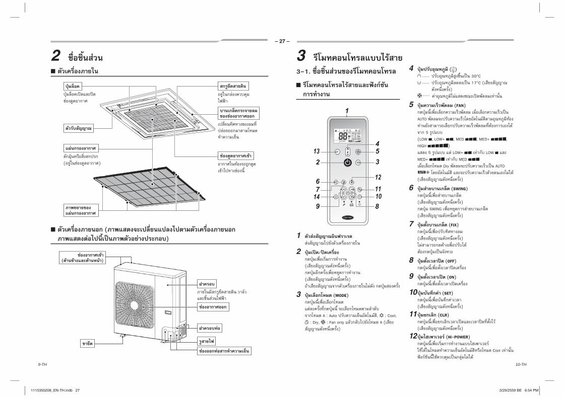
10-TH9-TH
– 27 –
2
( )
(
)
( )
3
3-1.
ON OFF
13
149
6
2
7
54
3
1211
810
1
1
2 /
( )
( )
3 (MODE)
A : Auto , : Cool,
: Dry, : Fan only A ()
4 ( )
30°C 17°C (
)
5 (FAN)
AUTO
5 (LOW , LOW+ , MED , MED+ , HIGH )
5 LOW+ LOW MED+ MED
Dry AUTO
( )
6 (SWING)
( ) SWING
( )
7 (FIX)
( )
8 (OFF)
9 (ON)
10 (SET)
( )
11 (CLR)
( )
12 (Hi-POWER)
Cool
1115350208_EN-TH.indb 271115350208_EN-TH.indb 27 3/29/2559 BE 6:54 PM3/29/2559 BE 6:54 PM

12-TH11-TH
EN
TH
TH
– 28 –
13 (PRESET)
3
P
14 (SLEEP)
4 (1, 3, 5 9 )
/
87546
1 23
•
1
( )
2
(A : Auto , : Cool, : Dry, : Fan only)
3
(17°C 30°C) : Fan only
4
AUTO 5 (LOW , LOW+ ,
MED , MED+ , HIGH ) : Dry
5
6 Hi POWER
High Power Hi-POWER
7 P
8
1
2 2 (R03 [AAA])
+ –
• 2 (R03 [AAA])
• 1 •
• 1
3-2.
AM 0:00
ON OFF 21
1 ON OFF
ON OFF
1 10
2
1115350208_EN-TH.indb 281115350208_EN-TH.indb 28 3/29/2559 BE 6:54 PM3/29/2559 BE 6:54 PM

14-TH13-TH
– 29 –
ON OFF
3
2
1
1
CLOCK •
2 ON OFF
ON OFF
1 10
3
3-3.
•
• •
•
•
-
•
• 8
8 .
• 1
( )•
• 2 ( 6 )
•
15
3-4.
1 ( 36)
2
3
“ ”
4 ( )
5 ( )
6 ( )
•
(
)
1115350208_EN-TH.indb 291115350208_EN-TH.indb 29 3/29/2559 BE 6:54 PM3/29/2559 BE 6:54 PM

16-TH15-TH
EN
TH
TH
– 30 –
3-5.
/
2
43
1
1 / ( )
2 (MODE)
(Cool) (Fan only)
3 ( )
(FAN ONLY)
4 (FAN)
, LOW , LOW+ , MED , MED+ , HIGH
• ( ) 3
( (FAN ONLY) )
• :
/ ( )
() 10 ( )
2
31
1 / ( )
2 (MODE)
(Dry)
3 ( )
• • ( )
3
/ ( )
() 10 ( )
(
)
2
3
14
1 / ( )
2 (MODE)
A
3 ( )
4 (FAN)
, LOW , LOW+ , MED , MED+ , HIGH
• ( )
3
•
/ ( )
() 10 ( )
1115350208_EN-TH.indb 301115350208_EN-TH.indb 30 3/29/2559 BE 6:54 PM3/29/2559 BE 6:54 PM

18-TH17-TH
– 31 –
ON OFF
231
1 ( ON OFF )
•
10 1
2
3
•
15 • 30
/
“ ”
(
)
—>
( —> —> )
:
1 OFF
2 ON
3
—>
( —> —> )
:
1 ON
2 OFF
3
•
•
(
)
1 ON
2 OFF
3
4 3 ( )
3
• ( , )
(ON-OFF, OFF-ON, OFF timer)
3
1115350208_EN-TH.indb 311115350208_EN-TH.indb 31 3/29/2559 BE 6:54 PM3/29/2559 BE 6:54 PM
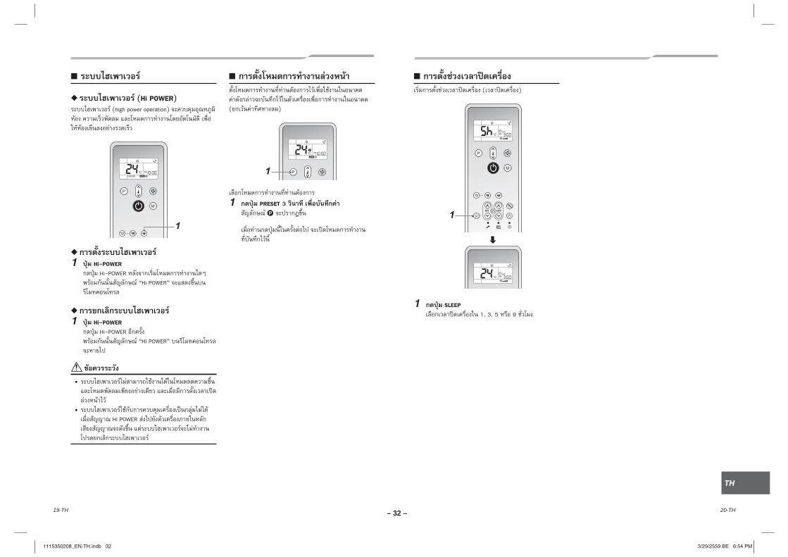
20-TH19-TH
EN
TH
TH
– 32 –
(Hi POWER) (high power operation)
1
1 Hi-POWER
Hi-POWER “Hi POWER”
1 Hi-POWER
Hi-POWER “Hi POWER”
•
• Hi POWER
( )
1
1 PRESET 3
P
( )
ON OFF1
1 SLEEP
1, 3, 5 9
1115350208_EN-TH.indb 321115350208_EN-TH.indb 32 3/29/2559 BE 6:54 PM3/29/2559 BE 6:54 PM

22-TH21-TH
– 33 –
4 8
4-1.
•
•
1
2
3
4
5
6
7
8
9
10
( ) ( ) ( ) ( )
11
12
( )
13
14
15
16
17
18
19
( : 01, 02, 03, 04)
20
( 1 1 )
1115350208_EN-TH.indb 331115350208_EN-TH.indb 33 3/29/2559 BE 6:54 PM3/29/2559 BE 6:54 PM
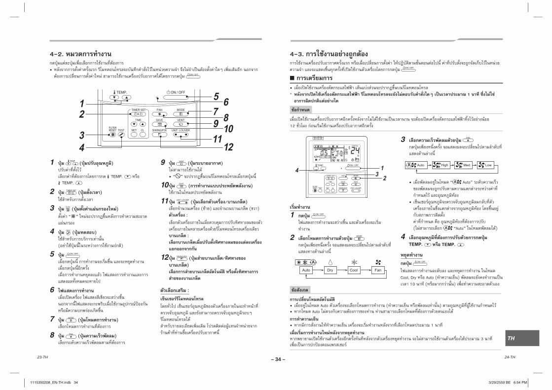
24-TH23-TH
EN
TH
TH
– 34 –
4-2.
•
1 ( )
2 ( )
3 ( )
“ ”
4 ( )
( )
5
6
7 ( )
8 ( )
9 ( )
• “ ”
10 ( )
11 ( / )
( ) ( ) :
:
12 ( /
)
:
4-3.
• * 1
12
1
2
3
• “ Auto”
•
( “Auto” )
4
Cool, Dry Auto ( )
10 ( )
• Auto ( ) • Auto
• 1
3
1115350208_EN-TH.indb 341115350208_EN-TH.indb 34 3/29/2559 BE 6:54 PM3/29/2559 BE 6:54 PM

26-TH25-TH
– 35 –
4-4. • : ( 168 )
: :
:
1
( ) ( ) ( )
•
2 “ ”•
0.5 (30 ) 24
1 168 (7 )
( 0.5 23.5 ) (*1) (24 ) (*2)
• 0.5 (30 ) (0.5 – 23.5 ) 1 (24 – 168 )
• 23.5 (*1)
• 34 (*2)
1 (24 )
10 ( 34 )
3
•
( )
4
•
•
5
4-5.
• •
•
1 4
• ,
2 ( )
• :
1-1 1-2 1-3
1-4
3
• 1% 100% 50%
• 75%
4
5
•
• ( 75% ( ) )
• /
1115350208_EN-TH.indb 351115350208_EN-TH.indb 35 3/29/2559 BE 6:54 PM3/29/2559 BE 6:54 PM

28-TH27-TH
EN
TH
TH
– 36 –
5 (
/ )
(COOL)
•
1
1 FIX
• FIX
FIX •
FIX
1
1 SWING
SWING • SWING
• FIX SWING ( )
• FIX
•
•
FIX
• 10
•
1
/
( / )
1 (
/ )
SWING /
1
•
*
/
2 • /
/
•
•
•
• :
1-1 1-2 1-3
1-4
1115350208_EN-TH.indb 361115350208_EN-TH.indb 36 3/29/2559 BE 6:54 PM3/29/2559 BE 6:54 PM

30-TH29-TH
– 37 –
1
( )
•
1-1 1-2 1-3
1-4
*
2
( )
• :
*
3
• :
* ( ) (4) (5)
6 /
/ ( )
• / / ( ) :
/ / ( )
10
10 1 1
1 2
• “ ” • ( ) ( )
START/STOP
• /
•
• ( )
•
1115350208_EN-TH.indb 371115350208_EN-TH.indb 37 3/29/2559 BE 6:54 PM3/29/2559 BE 6:54 PM
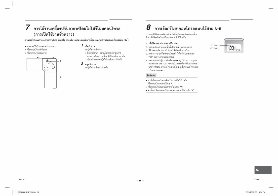
32-TH31-TH
EN
TH
TH
– 38 –
7
( ) :
1
•
2
• • •
8 A-B
2
B
1. 2. 3.
“00” 4. MODE “B”
“00” B
• A
• “A”• “A”
“B” “00”
1115350208_EN-TH.indb 381115350208_EN-TH.indb 38 3/29/2559 BE 6:54 PM3/29/2559 BE 6:54 PM
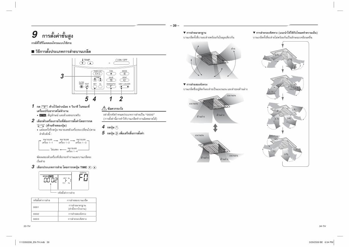
34-TH33-TH
– 39 –
9
1 4
• ,
2
( )
• :
1-1 1-2 1-3
1-4
3
0001( )
0002
0003
“0000” ( )
4
5
( )
1115350208_EN-TH.indb 391115350208_EN-TH.indb 39 3/29/2559 BE 6:54 PM3/29/2559 BE 6:54 PM

36-TH35-TH
EN
TH
TH
– 40 –
1 ( )
4
•
2 ( )
1-1 1-2 1-3
1-4
3 “ ”
4
* (4) (5)
5
(
2 3)
6
0001 - 0005(
)
* F1 CODE No. 01
:
•
“0000” 4 “
”
* 1-3 5-6 “ ”
1 “ ”
4
“01” CODE No.
2 ( )
1-1 1-2 1-3
1-4
3 “ ” CODE No.
“45”
4 “ ”
“0000”( )
“0002”(
)( )
5
6
*
1115350208_EN-TH.indb 401115350208_EN-TH.indb 40 3/29/2559 BE 6:54 PM3/29/2559 BE 6:54 PM

38-TH37-TH
– 41 –
10
( )
1. 2 2. START/STOP ( ON/OFF) 3.
• (
)
(1) “ ”
(2) “ ”
•
•
( )
3 3
( / )
// ,
/
/ , • •
• , • / ,
• •
/ // ,
/ ,
, / ,
• , • /
1115350208_EN-TH.indb 411115350208_EN-TH.indb 41 3/29/2559 BE 6:54 PM3/29/2559 BE 6:54 PM
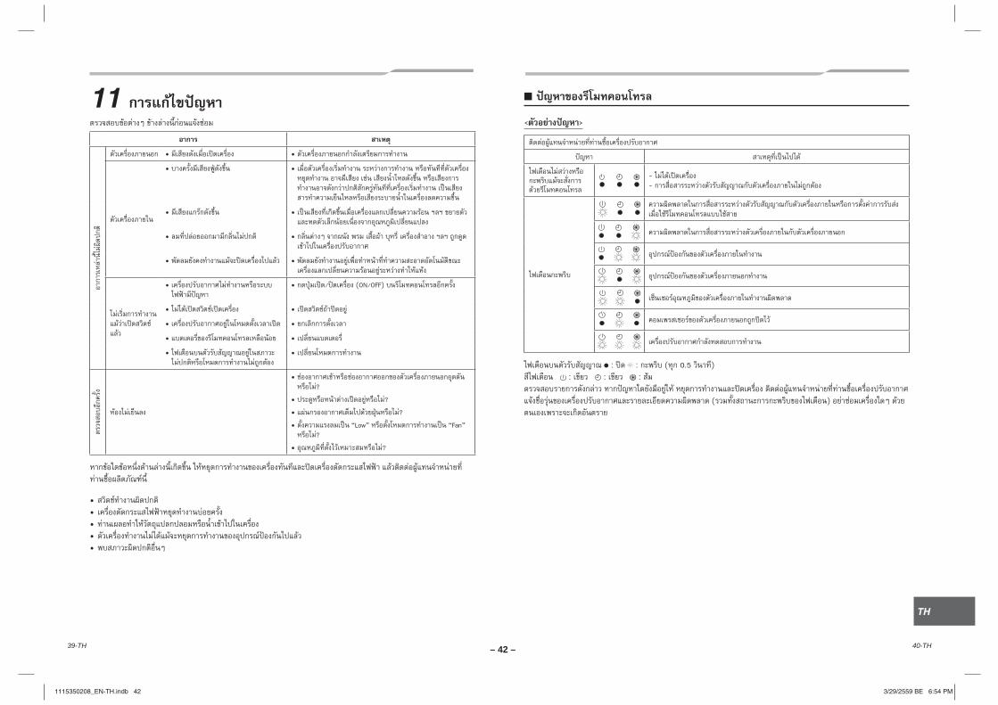
40-TH39-TH
EN
TH
TH
– 42 –
11
• •
• •
• •
• •
• •
• • / (ON/OFF)
• •
• •
• •
• •
• ?
• ?
• ?
• “Low” “Fan” ?
• ?
• • • • •
< >
- -
: : ( 0.5 ) : : :
( )
1115350208_EN-TH.indb 421115350208_EN-TH.indb 42 3/29/2559 BE 6:54 PM3/29/2559 BE 6:54 PM
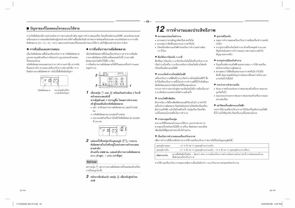
42-TH41-TH
– 43 –
( , , , )
“
”
(
4 )
1 4
• [01: ] CODE No.
• [ ] CHECK• [ ]
Unit No.
2
CODE No.
[01] ( ) → [04] ( )
3
• • •
12
3
3 3
3
/
( ) 8
•
•
•
•
•
•
/
12
:
: 15 °C 46 °C ( )
: 21 °C 32 °C ( ) , 15 °C 24 °C ( )
[ ] – 80%
1115350208_EN-TH.indb 431115350208_EN-TH.indb 43 3/29/2559 BE 6:54 PM3/29/2559 BE 6:54 PM
44-TH43-TH
EN
TH
TH
– 44 –
13
• 1 .
• ( )
•
• , • • • • • • (
) • ( ) (
)•
( )• ( 80%
) • •
•
• •
•
1115350208_EN-TH.indb 441115350208_EN-TH.indb 44 3/29/2559 BE 6:54 PM3/29/2559 BE 6:54 PM
– 45 –
MEMO................................................................................................................................................................................................................................................................................................................................................................................................................................................................................................................................................................................................................................................................................................................................................................................................................................................................................................................................................................................................................................................................................................................................................................................................................................................................................................................................................................................................................................................................................................................................................................................................................................................................................................................................................................................................................................................................................................................................................................................................................................................................................................................................................................................................................................................................................................................................................................................................................................................................................................................................................................................................................................................................................................................................................................................................................................................................................................................................................................................................................................................................................................................................................................................................................................................................
..................................................................................................
..................................................................................................
..................................................................................................
..................................................................................................
..................................................................................................
..................................................................................................
..................................................................................................
..................................................................................................
..................................................................................................
..................................................................................................
..................................................................................................
..................................................................................................
..................................................................................................
..................................................................................................
..................................................................................................
..................................................................................................
..................................................................................................
..................................................................................................
..................................................................................................
..................................................................................................
..................................................................................................
..................................................................................................
..................................................................................................
..................................................................................................
..................................................................................................
..................................................................................................
..................................................................................................
..................................................................................................
..................................................................................................
..................................................................................................
..................................................................................................
..................................................................................................
..................................................................................................
1115350208_EN-TH.indb 451115350208_EN-TH.indb 45 3/29/2559 BE 6:54 PM3/29/2559 BE 6:54 PM

– 46 –
EN
TH
MEMO................................................................................................................................................................................................................................................................................................................................................................................................................................................................................................................................................................................................................................................................................................................................................................................................................................................................................................................................................................................................................................................................................................................................................................................................................................................................................................................................................................................................................................................................................................................................................................................................................................................................................................................................................................................................................................................................................................................................................................................................................................................................................................................................................................................................................................................................................................................................................................................................................................................................................................................................................................................................................................................................................................................................................................................................................................................................................................................................................................................................................................................................................................................................................................................................................................................................
..................................................................................................
..................................................................................................
..................................................................................................
..................................................................................................
..................................................................................................
..................................................................................................
..................................................................................................
..................................................................................................
..................................................................................................
..................................................................................................
..................................................................................................
..................................................................................................
..................................................................................................
..................................................................................................
..................................................................................................
..................................................................................................
..................................................................................................
..................................................................................................
..................................................................................................
..................................................................................................
..................................................................................................
..................................................................................................
..................................................................................................
..................................................................................................
..................................................................................................
..................................................................................................
..................................................................................................
..................................................................................................
..................................................................................................
..................................................................................................
..................................................................................................
..................................................................................................
..................................................................................................
1115350208_EN-TH.indb 461115350208_EN-TH.indb 46 3/29/2559 BE 6:54 PM3/29/2559 BE 6:54 PM

1115350208
1115350208_EN-TH.indb 471115350208_EN-TH.indb 47 3/29/2559 BE 6:54 PM3/29/2559 BE 6:54 PM