air-conditioning systems · air-conditioning systems dieter bartel, manitoba hydro september 17 th,...
TRANSCRIPT

2011 Manitoba Energy Code for Buildings (MECB) ― PART 5, Heating, Ventilating and Air-conditioning Systems
Dieter Bartel, Manitoba Hydro September 17th, 2014

Outline
• Scope and compliance • Prescriptive path
• Ventilation, including heat recovery • Piping and pumping systems • Temperature control • Shut-off and setback controls • Equipment
• Trade-off path • Performance path
2

Scope
• Addresses HVAC - Part 5 • Piping and ducts forming part of the system • HVAC control systems • Air-conditioning equipment • Ventilating equipment • Heating equipment
3

Compliance options
• Simple prescriptive • Trade-off • Performance –
whole building
4

Air distribution
• Ability to balance • Duct Sealing
• Constructed and installed to SMACNA (Duct Construction Standards – Metal and Flexible)
• Sealed per static pressure classes ≤ 2”, > 2” and < 4”, ≥ 4”
• Exemptions
5

Duct and plenum insulation
• Requirements based on temperature difference
6
Temperature Difference,
°C
Min. Thermal Resistance for Ducts
and Plenums, m2•C/W
Min. Thermal Resistance for Run-outs,
m2•C/W
< 5 0 0 5 to 22 0.58 0.58 > 22 0.88 0.58

Cooling with outdoor air
• Ability to cool with outdoor air when • Mechanical A.C. capacity > 20 kW (5.5 tons) or • Air handler > 1500 L/s • Exception for dwelling units and hotel/motel rooms
• Direct use of outdoor air • Mixed air with up to 100% outside air (economizer) • > 20 tons = 25% capacity • > 6 and ≤ 20 tons = 50% capacity
• Water Economizer = provide 100% cooling
7

Fan systems
• Constant Volume (supply plus return) • 1.6 W per L/s (0.75 W per cfm)
• Variable Air Volume (supply plus return) • 2.65 W per L/s (1.25 W per cfm) and, • ≤ 55% design W at 50% design air flow when > 7.5
kW and < 25 kW
8
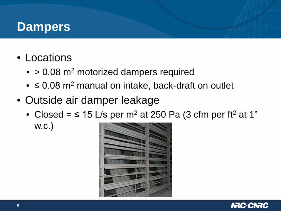
Dampers
• Locations • > 0.08 m2 motorized dampers required • ≤ 0.08 m2 manual on intake, back-draft on outlet
• Outside air damper leakage • Closed = ≤ 15 L/s per m2 at 250 Pa (3 cfm per ft2 at 1”
w.c.)
9
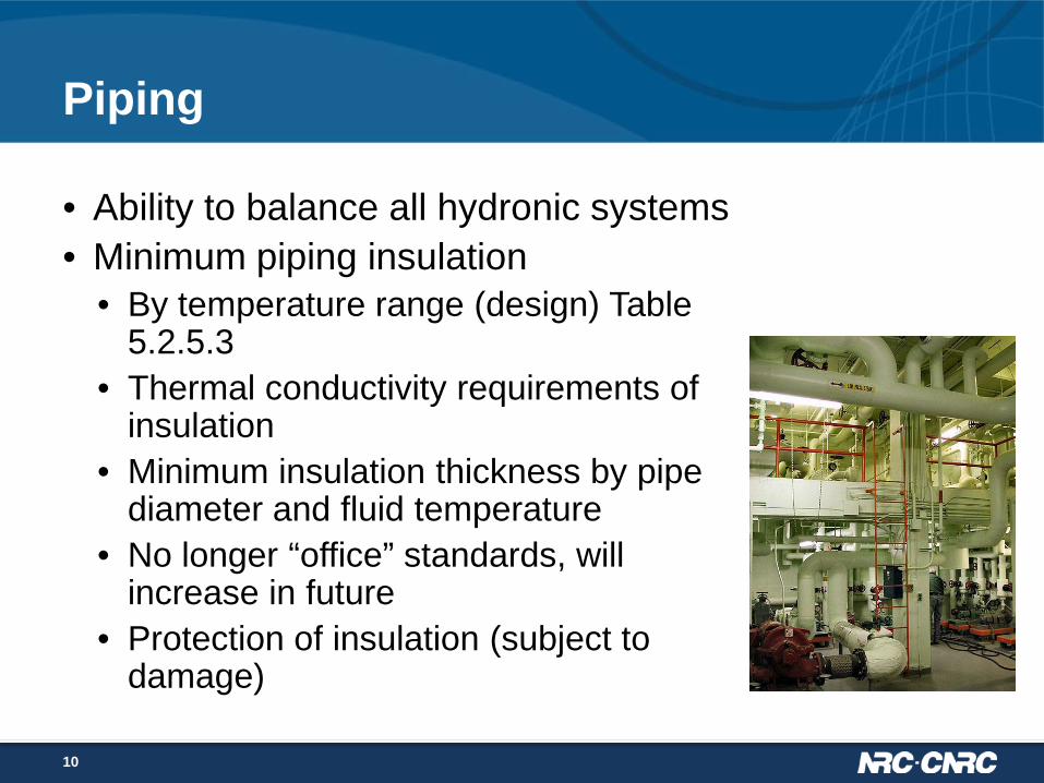
Piping
• Ability to balance all hydronic systems • Minimum piping insulation
• By temperature range (design) Table 5.2.5.3
• Thermal conductivity requirements of insulation
• Minimum insulation thickness by pipe diameter and fluid temperature
• No longer “office” standards, will increase in future
• Protection of insulation (subject to damage)
10

Pumping system
• Variable Flow Pumping • HVAC Pumping – control valves
• Variable fluid flow pumps > 7.5 kW (System Total) • Reduce system flow ≤ 50% • Nameplate power rather than break power
• Does not apply • Minimum flow > 50% (chiller or boilers) • Reset fluid supply temperature based on O.A. temp or load
11

Temperature controls
• Installations of thermostats • 1.4 – 1.5 m above floor, accurate to 1˚C • Exposure to sunlight or heat source • Away from drafts and dead air
• Heat Pump Controls • Prevention of supplementary heat if load can be met by
heat pump alone
12

Space controls
• Space Temperature Controls • Zone specific – heating and cooling • Independent (de-coupled) perimeter heating or cooling
systems allowed if: • One thermostat for each exposure • Heating and cooling controlled by control device in
zone • Vestibules require a device limiting temperature to
maximum 15˚C • Dwelling units
• At least one thermostat
13

Reheating and recooling controls
• Supply Air Handler Leaving Air Temperature • Controls required to achieve design supply air
temperature without: • Heating previously cooled air • Cooling previously heated air • Heating outside air in excess of the minimum for
ventilation
14

Reheating and recooling controls
• Control of Space Temperature by Reheating or Re-cooling • HVAC systems that control temperature of a space by
reheating previously cooled air shall be equipped with controls that automatically adjust the temperature of the cool air supply to the highest temperature that will satisfy the zone requiring the coolest air
15
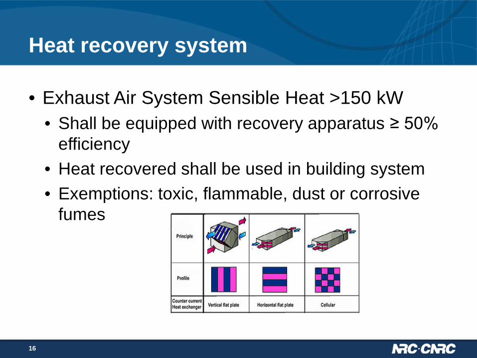
Heat recovery system
• Exhaust Air System Sensible Heat >150 kW • Shall be equipped with recovery apparatus ≥ 50%
efficiency • Heat recovered shall be used in building system • Exemptions: toxic, flammable, dust or corrosive
fumes
16

Heat recovery system
• Exhaust Air System Sensible Heat >150 kW Sensible Heat = 0.00123 x Q x (Te – To) Q = rated capacity of exhaust L/s Te = temperature of exhaust ˚C before heat recovery To = outdoor 2.5% January design temperature ˚C
• 2360 L/s at 55 ˚C temperature difference
17

Heat recovery – pools and ice surfaces
• Swimming pools • 40% recovery of sensible heat from exhaust air • Exemption if dehumidification system provides 80%
of dehumidification that would be accomplished by exhaust system
• Ice arenas • Required if heating load elsewhere • Allows use for either
space or service water heating
18
Heat recovery – dwelling units
• Dwellings with self-contained mechanical ventilation (except in climatic zones 4, 5 and 6) • Principal exhaust only • 2.5% January design temperatures which are less than and greater
than • <-10 C and >-30 C require 55% sensible HR efficiency • ≤ - 30 C require 45% sensible HR efficiency
19

Shut-off and setback controls
• Off-hours Controls • Dwelling units • Systems > 5 kW heating or cooling • Required to set back or up, or shut down • Reduce or shut off outside air when space not in use • Heat Pump – adaptive anticipation to prevent
supplementary heat during recovery
20

Airflow control areas
• Air Flow Control Areas • Size > 2500 m2 shall be divided into Air Flow Control
Areas • Or systems shall serve < 2500 m2 • Shall have separate shut-off and set back control • Each AFCA limited to one storey • DDC controls required
21

Boiler controls
• Multiple Boilers • > 176 kW (600,000 Btuh)
• More than one boiler or, • 2 stage or multi-stage firing
• > 352 kW (1,200,000 Btuh) shall be fully modulating
22

Temperature Reset
• Loop Temperature Reset • Chilled or Hot Water Systems > 88 kW (300,000 Btuh) • Indoor/outdoor controller, or, • Represent building load using return water temperature
23

Equipment – minimum performance efficiency
• Efficiency with referenced standards provided for:
24
− Boilers − Warm-air furnaces − Duct furnaces − Unit heaters − Packaged water chillers − Packaged terminal A/C − Computer room A/C
− Air-cooled A/C and heat pumps
− Water- and evaporatively cooled A/C and heat pumps
− Condensing units − Ground water heat pumps

Equipment – minimum performance efficiency
• Table 5.2.12.1 HVAC Equipment Performance Requirements • Component groups and capacities • Referenced Standards and Rating Conditions • Minimum performance in EER, COP, IPLV, AFUE, Ec
and Et • Some equipment requirements set to median of current
practice • Most aligned with EE regulations from early 2010
25

Equipment – minimum performance efficiency
26
Boilers Equipment Heating Capacity
kW (Btu/h) MECB
Minimum Performance
Energy Efficiency
Regulations Gas-fired < 88 kW (300,000) AFUE = 85% AFUE = 82%
≥ 88 kW and < 733 kW (2,500,000)
Ec ≥ 82.5% Et ≥ 83%
N/A
≥ 733 kW Ec ≥ 83.3% Oil-fired < 88 kW (300,000) AFUE ≥ 84.7% AFUE ≥ 84%
≥ 88 kW and < 733 kW (2,500,000)
Et ≥ 83.4% N/A
≥ 733 kW Ec ≥ 85.8%

Equipment – minimum performance efficiency
27
Warm-Air Furnaces, Duct Furnaces and Unit Heaters Equipment Heating
Capacity kW (Btu/h)
MECB Minimum Performance
Energy Efficiency Regulations
Gas-fired furnaces
≤ 117.23 (400,000)
AFUE ≥ 94% (Manitoba)
≤ 66 kW ≥ 90% > 66 ≤ 117 kW, ≥
80% > 117.23 Et ≥ 81% N/A
Gas duct furnaces
≤ 117.23 kW Et ≥ 81% N/A
Gas unit heaters
≤ 117.23 kW Et ≥ 82% Et ≥ 80%
Oil-fired furnaces
≤ 66 kW (225,000)
Et ≥ 84.5% Et ≥ 78%
> 66 kW Et ≥ 81.3% N/A

Restrictions
• Equipment performance efficiency cannot be less than required by Energy Efficiency Regulations, or provincial/territorial requirements, if more stringent
• Back-up equipment must comply with prescriptive path
28

Trade-off concept
• Considers energy use throughout system
29

Trade-off concept
• System efficiency approach considers HVAC system as a whole
• Allows improvement in other system parts to compensate for one component not meeting a prescriptive requirement
• Intended to permit flexibility for typical design
30
Total proposed Total reference system efficiency system efficiency ≥

Components and systems considered
• Comparison: system to same system
• 27 common system types considered
• 32 components considered
31
From DOE 2.2 User manual

Method
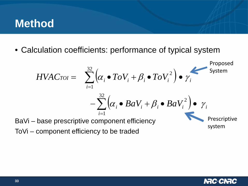
• Calculation coefficients: performance of typical system
BaVi – base prescriptive component efficiency ToVi – component efficiency to be traded
32
( )
( ) ii
iiii
ii
iiiiTOI
BaVBaV
ToVToVHVAC
γβα
γβα
••+•−
••+•=
∑
∑
=
=
32
1
2
32
1
2
Method
• Calculation coefficients: performance of typical system
BaVi – base prescriptive component efficiency ToVi – component efficiency to be traded
33
Proposed System
Prescriptive system
( )
( ) ii
iiii
ii
iiiiTOI
BaVBaV
ToVToVHVAC
γβα
γβα
••+•−
••+•=
∑
∑
=
=
32
1
2
32
1
2

Coefficients
• Likely computer-program-assisted but can be completed with spreadsheet
34
Built-up Variable Volume
Component XDD α1 α2 α3 β1 β2 β3 ToV1- Supply Fan
Mechanical Efficiency HDD 9.901E-01 -1.418E-04 5.710E-09 -5.191E-01 7.037E-05 -2.626E-09 ToV2 -Supply Motor
Efficiency HDD 6.994E-01 -1.013E-04 4.055E-09 -2.670E-01 3.687E-05 -1.362E-09
ToV3- Return Fan Mechanical Efficiency HDD 6.087E-01 -5.513E-05 7.352E-10 -5.244E-01 4.324E-05 -2.153E-10
ToV4 - Return Fan Motor Efficiency HDD 2.916E-01 -2.712E-05 3.972E-10 -1.264E-01 1.095E-05 -8.620E-11
ToV5 -Supply Temperature Control HDD -2.175E-01 1.610E-04 -1.976E-08 1.081E+00 -3.448E-04 2.887E-08
ToV6 - Airflow Control Efficiency TDD 1.034E-01 3.422E-05 -3.997E-09 8.110E-01 -2.076E-04 1.353E-08

Spreadsheet
35
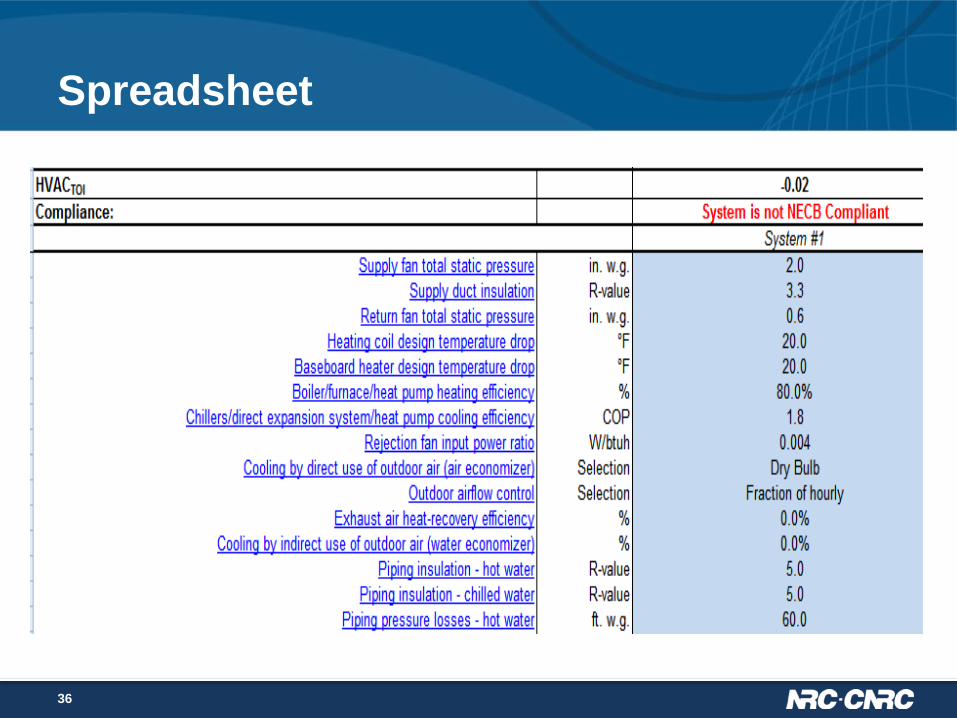
Spreadsheet
36

Trade-off limitations
• Energy sources used must be natural gas, propane, oil or electricity
• Back-up equipment must meet prescriptive requirements
• One of the 27 “traditional” systems
37

2011 Manitoba Energy Code for Buildings (MECB) ― PART 6 Service Water Heating
Dieter Bartel, Manitoba Hydro September 17th, 2014

Outline – Part 6
• Scope and compliance • Prescriptive requirement
– Equipment – Piping and storage tank insulation – Controls – Hot water discharge flow
• Trade-off path • Performance path
39

Scope
• Addresses service water heating (SWH) – Heating equipment – Piping insulation – Controls – Hot water discharge flow
“Service water means water for plumbing services, excluding systems exclusively for space heating or cooling or for processes”
40

Compliance path
• Prescriptive • Trade-off path • Performance
path
41

Equipment minimum performance efficiency
• Equipment minimum efficiency performance • Table 6.2.2.1 SWH Equipment Performance
Standards • Aligned with Energy Efficiency Regulations (EER)
as of May 2010 • Performance required shall not be lower than
MECB, EER, or Provincial Requirements (most stringent shall apply)
• Standby losses (SL), Thermal Efficiency (Et), Energy Factor (EF)
42

Equipment minimum performance efficiency
• Manitoba Amendments
43
Water Heaters Input Performance Requirement
Gas-fired instantaneous
≥ 14.7 kW and ≤ 73.2
kW
EF ≥ 0.8
Gas-fired storage
≤ 21.98 kW EF ≥ 0.67 – 0.0005 V
Gas- Fired storage
> 21.98 kW and ≤ 117 kW
Et ≥ 80%

Equipment insulation
• Equipment Insulation • Storage Tank Insulation – maximum U-value • O.45 W/(m2∙K) or (0.08 Btu/h∙ft2∙F)
• Combination SWH and Space Heating • Permitted where input to combo unit is: • < 22 kW (75,000 Btuh) or, • < twice SWH load
44

Piping insulation
• Required for • Hot water circulation systems • Hot water non-circulation
systems – Without heat traps – With heating elements or heat
tracing • Minimum thickness table for
conditioned and non-conditioned spaces
45

Placement
• Clarification on heat traps requirements and location of insulation on runouts
46

Controls
• Systems with storage tanks – Automatic temperature control
• Controls for heat maintaining system required
• Seasonal shutdown controls required
47

More than one end-use temperature
• Booster Heaters required when • More than one end use temperature on system • Design discharge temperature is > 60 ˚C, and, • < 50% of the total design flow
48

Showers and lavatories
• Individual Showers (Manitoba) • Maximum hot water discharge 6.6 L/min (1.45 Imp
gal/min) • Lavatory Faucets (Manitoba)
• Maximum hot water discharge 5.7 L/min (1.25 Imp gal/min)
• Automatic shut-off valves for assembly occupancies
49
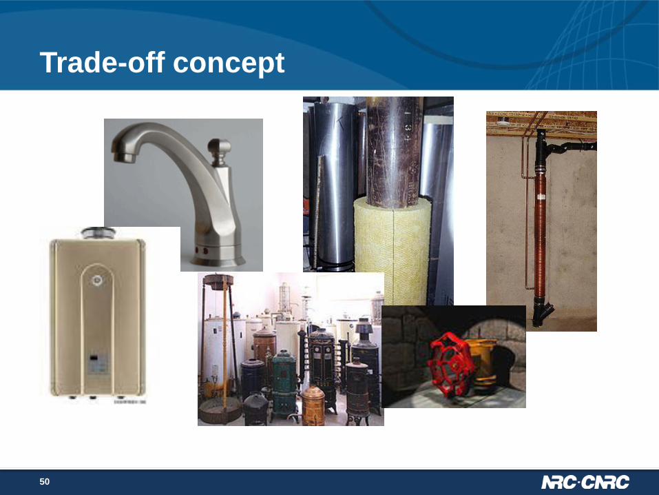
Trade-off concept
50

Trade-off concept
• System efficiency approach considers SWH system as a whole
• Allows improvement in other system parts to compensate for one component not meeting a prescriptive requirement
51
Total proposed Total reference system efficiency system efficiency ≥
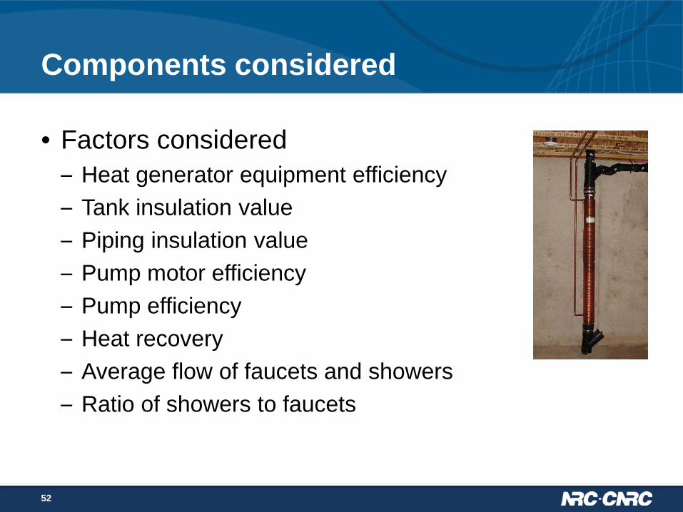
Components considered
• Factors considered – Heat generator equipment efficiency – Tank insulation value – Piping insulation value – Pump motor efficiency – Pump efficiency – Heat recovery – Average flow of faucets and showers – Ratio of showers to faucets
52

Systems considered
• Comparison: system to same system • Three system types:
– Tank – Instantaneous – Originating from space
heating boiler
53

Method
• Parameters entered into equation for system – Example: tank system
• System complies if SWH-TOI > 0
54
{ }
0141.0807.612.4
06153.0813.2813.2
ToVToV00677.0
ToV180.26
ToV06153.0
ToV6514.01 ToV
813.2
813.2
1
1
5432
ToV312.06
1
6
−
−•−
+
+•+•−
•+
+•+
••−••
•=−
norm
ref
norm
A
A
ePDR
TOISHW
η

Trade-off limitations
• Energy sources used must be natural gas, propane, oil or electricity
• Back-up equipment must meet prescriptive requirements
• One of the 3 “traditional” systems
55

Performance Path
• Equipment performance efficiency cannot be reduced below those of EE Regulations
• Back-up equipment must comply with prescriptive path
56

Thank you