air conditioning and cooling system simulation ... · thermotec engineering services gmbh air...
TRANSCRIPT

Thermotec Engineering Services GmbH
Air Conditioning and Cooling System
Simulation /
Approaches to Handle Data and Huge
Number of Variations
Robert Tauscher

Overview
■ Introduction
■ Our daily business
■ System complexity and number of variants
■ Approaches to handle complexity and variants
■ Examples
■ Component Level: Subassembly Evaporator, Condenser, HX
■ System Level: Universal System Template
■ Modeling and Calibration Level: System Identification
■ Calibration Level: Hydraulic, Thermal
■ Verification Level
■ Conclusion

Who is Thermotec?
■an engineering company - 15 engineers and physicists -
specialized on thermodynamics and .fluid mechanics
■automotive, aerospace and defense industries
■simulation: thermal/hydraulic systems, thermal
management and cooling .systems
(1D and 3D-CFD)
■ test benches: wind tunnel for radiator and heat exchanger
performance tests
■sensor development / measurement techniques
■cooperations with universities / research projects
■our partners:
www.thermotec-es.com
Technische
Universität
München

Our Daily Business - General
■ Analysis of AC and Cooling Systems
■ Evaluation of concepts, variants, …
■ Dimensioning of components / complete systems
■Control Strategies:
■ Development and Proof of Concept
■ Failure Scenarios and Backup Strategies
■What if … analysis
■ Dimensioning / Scaling
■ Pumps, fans (size, operating points, …)
■ Radiators (scaling)
■ Piping (pressure drop diameter, etc.)
■ Comparison of concepts / components …

Our Daily Business - Simulation
■ Modeling
■ Physical or
■ System Identification
■ Verification: compare model with experimental data
■ Experiment
■ Data collection and pre-processing
■ Steady state and transient
■ Model Calibration (experiment, 3D-CFD, …)
■ Component level
■ System level
■Post-processing / Analysis
■Presentation / Documentation …

■2ph-/AC-System integration in vehicle cooling system model
■vehicle model system generation / data handling / huge number of variantssystem
Q
Qair
Q
Q
Q
Q
Q
Q
Q
Challenge: Cooling System & Control Strategy for a System with
Battery & Power Electronics + AC-System
DT: +5K DT: +5K DT: +50KT.ambient DT: +2…5K
■cabin modeling / system identification
■cabin calibration
■HX, condenser… sub-model generation
■piping/hydraulics calibration
component
direction of heat flow / heat transfer
loss of thermodynamik potenzial / „thermal resistance“

Approaches
Multiple Coupled AC and Cooling System Simulation / Automated
Handling of Data and Variations: Challenges and Approaches
Challenges
large
number of
concepts to
be
evaluated
large
number of
subsystems
within a
model
huge
number of
variants and
derivatives
of a model
frequent
changes of
data during
design
process
very complex
calibration of
model and
subsystems
to experiment
coupled
simulation &
harware in the
loop (HiL),
controls
simulation
time
convergence
evaluation
documentation
robustness
reproducibility
.
Universal System Model Template
steady-state / transient
calibration
fast running / real-time
.n
e
.. .
.
.
.
.
..
.
.
.
.
.
.
.. ..
...
system identification
major sub-systemsthermal / hydraulic
simulation model
universal
system
model
template
database for
models,
components
and data
physical
modelling,
system
identification
automated
start & check
of
simulations
semi-
automatic
model and
subsystem
calibration
automated
standard
and custom
made
evaluation
scripted
generation
of models,
components
and variants
modular
simulation
set,
defined
interfaces

Vehicle AC and Cooling System –
From a Simple Model to Complex Systems
and a Huge Number of Variants
The Challenge:
■ 1
■ 10
■ 40 … 55
■ 5.000 … 11.000
■ 25.000 … 110.000
■ 1 … 700 x 10 … 100
■ 26.000
Gamma‘s example of a simple air-
conditioning circuit with battery
cooling
(„System_Battery_Cooling“)
Facts & model data of a
state of the art vehicle air-
conditoning circuit & coupled
cooling system model
?
what is necessary and
how will the model look like,
that we can meet
the challenges?

Vehicle Cooling System – Model Complexity and Variants 2016
1
10
40 … 53 (*50)
5.000 … 11.000 (*10.000)
25.000 … 110.000 (*100.000)
1 … 700 (*400) x 10 … 100
26.000 (*15.000)
(* GT-User Confernce 2015!)
■ Universal modular GT-System-Model-Template
■ Fluid Circuits: coolant (ht, lt,…), oil, air, refrigerant …
■ External subassemblies - main modules of vehicle
■ Total number of GT-parts in 1 model
■ Code lines in a „ready-to-simulate“ model file (*.dat-file)
■ Simulations/1 night (variants x use cases)
■ Result files (700 variants with 10 use cases)
up to:

Automation in Each Level of Simulation Workflow
■ Component Level - Automatic Component-model creation
■ Evaporator, Condenser, Radiator, Heat exchanger
■ System Level – Automatic Multiple/Cascades Coupled AC-Cooling-System creation
■ Universal System Model Template
■ Modelling & Calibration Level - System Identification
■ Calibration Level - Model Calibration (steady state, transient…)
■ hydraulic
■ hydraulic & thermal, …. Maximum Likelihood Optimization
■ Analysis Level / Presentation Level – Custom Made Offline Evaluation Tool
■ Verification Level – Development of Sensors and Measurement Techniques

Automation – Component Level:
Component Generation*/Heat Exchanger: Evaporator, Condenser, ..
Evaporator, HX
Condenser, Radiator
type (cross-flow, …)
geometry, dimensions
hydraulic and thermal
performance
properties of matter
Process Relevant Data
manual step
Data Sheet (GT-Excel-
Template or Custom)
automatic step
*details in GT-User-Conference 2015 presentation
dimensions
properties of matter
hydraulic (Dp)
thermal efficiency
NTU-limits
…
correction if necessary
Check Input Data
dimensions
height
# tubes
width
depth !
fins: spacing /
thickness
tubes: wall thickness
Scaling
(optional)
Visual Check & Last
Modifications
Generation of
GT-Subassembly
and Automatic Pre-
processing
evap./cond/HX-test
bench
Documentation of Nu-
Re-Regression Quality
correction of regression
to meet raw data (option)
add Model to
Component Database

Universal Modular
System Model Template
for each variant:
all relevant model
parameters and data
sheets
list of all relevant
external Subassemblies
for each model variant
Database of Variants /
Variants Parts List
automatic step
Coupled AC and Cooling System Simulation – Automated
Handling of Data and Variations* Check
check consistency of
data:
- parameters
- subassemblies
combination
- boundary
conditions
- …
generate
*.gtm file for each variant
*.dat file for each variant
check: all models
generated?
log file of variants
Model Generation
check workload of
cluster server and
available licenses
send models to
distributed server
Simulation /
Batch / Distributed Run
Check Simulations /
Process Results
check simulations
- all runs finished?
- convergence?
option: re-start
simulation of selected
models (failed,
crashed…)
Process Results
collect and combine
results / first check
Data Reduction &
Evaluation
Excel-Add-In and
template for results:
steady state / transient
0
1
2
3
4
5
6
7
8
0
20
40
60
80
100
120
140
160
0 200 400 600 800 1000 1200
Gan
g
Fahr
zeug
gesc
hwin
digk
eit
[km
/h],
Tem
pera
ture
n [°C
]
F56Ha B48 170kW, Guadix, kinematisch vs gemessen
Fahrzeug_output_Geschw #1_GT_2 WT_KMKHT_output_T_WT_Ein_Inner #1_GT_2
WT_MOEWWT_output_T_WT_Ein_Inner #1_GT_2 WT_GOEWWT_output_T_WT_Ein_Inner #1_GT_2
T_KM_KMKHT_ein Guadix_Messung T_MO_MOEWWT_ein Guadix_Messung
T_GO_GOEWWT_ein Guadix_Messung Fahrer_Gang #1_GT_2
Reporting /
Sharing of Results
- standard report
- interactive evaluation
. tool
Documentation …
archiving
documentation
data proc. for 3rd
party use (3D-CFD…)
clean up
- delete huge
number of files
- free disk space
*details in GT-User-Conference 2015 presentation

System Battery/Power Electronics + AC-System
■Cooling strategy for system HVS (high voltage storage) + Power Electronics (PE)
■Cooling strategy for AC-System + Cabin
■ Integration in Vehicle Cooling System Model
■ multiple cascaded coupling via fluid circuits (chiller / multi-stage) and via
underhood flow
■ modular universal system model
■Simulation Time / Robustness / Convergence …
HVSCabinEvaporator
CondenserSystem
Hydraulics

■ Calibration of Cabin and AC model to Pull-Down measurements
Modelling & Calibration Level: System Identification
air flow
temperature
flow rate
…
Pull-Down Measurement: transient
temperatures at many cabin positions
cabin model template
needs a lot of – often
unknown – input data
calibration to transient
temperatures at many
sensor positions
Ambient: 3
Vehicle: 4
Component Materials: 13
Component Masses: 7
Component Geometry: 13
View Factors: 7
Cabin Initial State: 11
Solar Properties: 7
Miscellaneous: 6
Layer Weighting: 18
Thermal Comfort Pred.: 3
GT-Post-Output:1
Plots: 5
----------------------------
Total: 98 (!) data fields
Cabin Template

System
u (t) : input y (t): output
v (t) : disturbances
exp.ht_target/T_Head_rig
xp.t_target/eT_Head_lef
exp.ht_target/T_Feet_rig
xp.t_target/eT_Feet_lef
y(t)
RT_Louver_C
LT_Louver_Cu(t)
T_Louver
(L+R)T_Feet (L+R)
T_Head(L+R
)
■ transient behavior of components and systems very often cannot be described
sufficiently by simple physical models
■e.q. thermal masses / thermal inertia / thermal resistance of cabin model or
engine
■with transient test data available dynamical models can be obtained by system
identification (transfer function between input and output, regarding
disturbances)
■ these models - generated in MATLAB/SIMULINK - can be utilized in GT-Suite
as SimulinkHarness-Objects replacing the standard cabin model object
System Identification
System Cabin
transfer function

identified
State-Space Model
cabin.dll
T_Louver (L+R)
T_Feet (L+R)
T_Head(L+R)
RT_Louver_C
LT_Louver_Cu(t)
exp.ht_target/T_Head_rig
xp.t_target/eT_Head_lef
exp.ht_target/T_Feet_rig
xp.t_target/eT_Feet_lef
y(t)
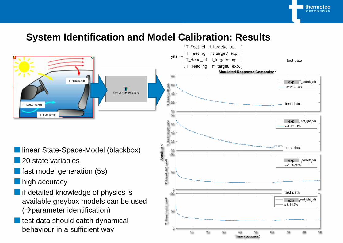
Modelling & Calibration Level: System Identification
Implementation in GT-Suite Model
T_Louver (L+R)
T_Feet (L+R)
T_Head(L+R)
test data
test data
test data
test data
■ linear State-Space-Model (blackbox)
■20 state variables
■ fast model generation (5s)
■high accuracy
■ if detailed knowledge of physics is
available greybox models can be used
(parameter identification)
■ test data should catch dynamical
behaviour in a sufficient way
System Identification and Model Calibration: Results
exp.ht_target/T_Head_rig
xp.t_target/eT_Head_lef
exp.ht_target/T_Feet_rig
xp.t_target/eT_Feet_lef
y(t)
exp
exp
exp
exp

Automation – Calibration Level: Model Calibration - Hydraulics
Goal: hydraulic calibrated GT-model for each use case / control strategy @each branch in
coolant circuit, esp. local flow rates and pressure distribution
System
MEADS Radar Unit
many communicating parallel - but
different - flow paths to be calibrated
(100)
piping of refrigerant loop
CAD GEM3D
3D-CFD / experiment
interface GT-hydraulic model
subassembly
hose and piping
system
PID-controlled
orifices for each
sector and branch
automatic calibration
for each use case
hydraulic calibrated
model

Automation – Calibration Level: Model Calibration – Thermal, …
■ Goal: find measurement errors and model calibration factors for
■ heat flow: heat rejection engine, air cond, gear box, …
■ flow rates: refrigerant, coolant, air, oil, atf, …
■ performance maps: heat exchangers, pumps, …
■ that the model can reproduce measured
■ temperatures
■ pressures
■ flow rates, …
■ for all (sensor) positions
■ simultaneously and for all use cases
■ as automatic as possible
■ comply with mass and energy conservation! consistent solution

Calibration Level: Model Calibration and Test Data Validation
based on Maximum Likelihood Optimization
■ Goal: find measurement errors and model calibration factors
■GT-Model based on maps for single components
(Compressor, Condenser,…) and certain boundary
conditions
■component maps usually derived from tests or simulation
GT- Model test bench
pGT, TGT, mdotGT ≠ ptest, Ttest, mdottest
reasons for deviations (simulation vs. experiment):
■component data (maps, …) imprecise?
■system model inaccurate?
■measurement errors (e.g.temperatures)?
■or a combination of both? most likely!
Maximum Likelihood Optimization
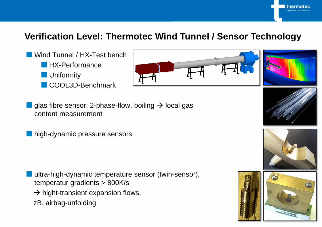
■ Wind Tunnel / HX-Test bench
■ HX-Performance
■ Uniformity
■ COOL3D-Benchmark
■ glas fibre sensor: 2-phase-flow, boiling local gas
content measurement
■ high-dynamic pressure sensors
■ ultra-high-dynamic temperature sensor (twin-sensor),
temperatur gradients > 800K/s
hight-transient expansion flows,
zB. airbag-unfolding
Verification Level: Thermotec Wind Tunnel / Sensor Technology

■ capacitive gas content sensor aeration z.B. engine oil
■ wire-mesh sensor / phase and/or component distribution
■ verification simulation filling/degassing
■ verification simulation fording ability
■ Berner Impactor / Particle Image Velocimetry (PIV)
■ verification simulation particel flow
■ contact angle measurement
■ verification fogging and steaming up
Verification Level: Thermotec Sensor Technology

Automation – Evaluation / Presentation Level
■Custom Made & Interactive Evaluation and Presentation Tools for
■ Off-Line Usage (no licenses required)
■ „Non-Experts“
■ Marketing Purposes

Conclusion
■ What is necessary to handle and simulate complex AC and cooling systems and
what is possible with Gamma Technologies GT-Suite?
■ Models / Simulation
■ Short simulation times fast running models (FRM) / fast convergence
■ Robust models
■ Modelling
■ Automation of model generation (VBA)
■ Component and system-model generation / modification
■ Co-simulation with System Identification / Simulink (SimulinkHarness)
■ Model data: administration in external file(s) or database (Excel)
■ Tools to model specified components very detailed
■ Simulation
■ Automation of pre- and post-processing (VBA, Excel)
■ Automation and organisation of simulation-runs 24/7 workload of server and
licenses (VBA, Excel)
■ Automation of model calibration (VBA and GT)

Thank You for Your Attention!
www.thermotec-es.com