air conditioning and refrigerationbooks.mcgraw-hill.com/engineering/pdfs/miller.pdf · air...
TRANSCRIPT

Air Conditioningand
Refrigeration
FM_Miller.qxd 2/28/06 1:58 PM Page i

FM_Miller.qxd 2/28/06 1:58 PM Page ii
Air Conditioningand
RefrigerationREX MILLERProfessor Emeritus
State University College at BuffaloBuffalo, New York
MARK R. MILLERProfessor, Industrial TechnologyThe University of Texas at Tyler
Tyler, Texas
McGraw-HillNew York Chicago San Francisco Lisbon London
Madrid Mexico City Milan New Delhi San JuanSeoul Singapore Sydney Toronto
FM_Miller.qxd 2/28/06 1:58 PM Page iii

Library of Congress Cataloging-in-Publication Data
Miller, Rex, date.Air conditioning and refrigeration / Rex Miller, Mark R. Miller.
p. cm.Includes index.ISBN 0-07-146788-21. Air conditioning. 2. Refrigeration and refrigerating machinery. I. Miller, Mark R.
II. Title.
TH7687.M4855 2006621.5′6—dc22 2005058099
Copyright © 2006 by The McGraw-Hill Companies, Inc. All rights reserved. Printed inthe United States of America. Except as permitted under the United States Copyright Actof 1976, no part of this publication may be reproduced or distributed in any form or byany means, or stored in a data base or retrieval system, without the prior written permis-sion of the publisher.
1 2 3 4 5 6 7 8 9 0 QPD/QPD 0 1 2 1 0 9 8 7 6
ISBN 0-07-146788-2
The sponsoring editor for this book was Larry S. Hager and the production supervisorwas Pamela A. Pelton. It was set in Times by International Typesetting andComposition. The art director for the cover was Handel Low.
Printed and bound by Quebecor/Dubuque.
McGraw-Hill books are available at special quantity discounts to use as premiums and salespromotions, or for use in corporate training programs. For more information, please write tothe Director of Special Sales, McGraw-Hill Professional, Two Penn Plaza, New York, NY10121-2298. Or contact your local bookstore.
This book is printed on acid-free paper.
Information contained in this work has been obtained by TheMcGraw-Hill Companies, Inc. (“McGraw-Hill”) from sourcesbelieved to be reliable. However, neither McGraw-Hill nor itsauthors guarantee the accuracy or completeness of any informationpublished herein, and neither McGraw-Hill nor its authors shall beresponsible for any errors, omissions, or damages arising out ofuse of this information. This work is published with the under-standing that McGraw-Hill and its authors are supplying infor-mation but are not attempting to render engineering or otherprofessional services. If such services are required, the assistanceof an appropriate professional should be sought.
FM_Miller.qxd 2/28/06 1:58 PM Page iv

Voltmeter 25Ohmmeter 26Multimeter 26Wattmeter 27
Other instruments 28Air–Filter Efficiency Gages 28Air-Measurement Instruments 28Humidity-Measurement Instruments 29Vibration and Sound Meters 29
Service Tools 30Special Tools 31Vacuum Pumps 32
Vacuum Pump Maintenance 34Vacuum Pump Oil Problems 34Operating Instructions 34Evacuating a System 35
Charging Cylinder 35Charging Oil 36Changing Oil 37Mobile Charging Stations 37Tubing 37
Soft Copper Tubing 37Hard-Drawn Copper Tubing 38Cutting Copper Tubing 39Flaring Copper Tubing 40Constricting Tubing 41Swaging Copper Tubing 41Forming Refrigerant Tubing 42Fitting Copper Tubing by Compression 43
Soldering 43Soft Soldering 44Silver Soldering or Brazing 46
Testing for leaks 47Cleaning and Degreasing Solvents 47Review Questions 47
2 Development of Refrigeration
Performance Objectives 50Historical Development 50
Contents
Preface xvAcknowledgments xvii
1 Air-Conditioning andRefrigeration Toolsand Instruments
Performance Objectives 2Tools and Equipment 2
Pliers and Clippers 2Fuse Puller 2Screwdrivers 2Wrenches 3Soldering Equipment 3Drilling Equipment 4Knives and Other Insulation-Stripping Tools 5Meters and Test Prods 6Tool Kits 7
Gages and Instruments 9Pressure Gages 9Gage Selection 10Line Pressure 11Effects of Temperature on Gage Performance 12Care of Gages 12Gage Recalibration 12
Thermometers 13Pocket Thermometer 13Bimetallic Thermometers 15Thermocouple Thermometers 16Resistance Thermometers 16Superheat Thermometer 17
Superheat Measurement Instruments 17Halide Leak Detectors 21
Setting Up 21Lighting 22Leak Testing the Setup 22Adjusting the Flame 22Detecting Leaks 22Maintenance 22
Electrical Instruments 23Ammeter 23
v
FM_Miller.qxd 2/28/06 1:58 PM Page v

Structure of Matter 50Elements 51Atom 51
Properties of Matter 51Pressure 52
Pressure Indicating Devices 52Pressure of Liquids and Gases 53Atmospheric Pressure 53Gage Pressure 53Absolute Pressure 53Compression Ratio 54
Temperature and Heat 54Specific Heat 55Heat Content 55Sensible Heat 55Latent Heat 55Other Sources of Heat 56
Refrigeration Systems 56Refrigeration from Vaporization(Open System) 56
Basic Refrigeration Cycle 56Capacity 57Refrigerants 57Refrigerant Replacements and the Atmosphere 58
Review Questions 59
3 Voltage, Current, andResistance
Performance Objectives 62Ohm’s Law 62Series Circuits 62Parallel Circuits 64
Current in a Parallel Circuit 64Resistance in a Parallel Circuit 65
AC and DC Power 65Phase 66Power in DC Circuits 66
Power Rating of Equipment 67Capacitors 67
How a Capacitor Works 68Capacity of a Capacitor 69Dielectric Failure 69Basic Units of Capacitance 69Working with Capacitive Values 69Capacitor Types 70Capacitor Tolerances 73
The AC Circuit and the Capacitor 73Uses of Capacitors 75
Inductance 75Four Methods of Changing Inductance 75Self-Inductance 75Mutual Inductance 76Inductive Reactance 77Uses of Inductive Reactances 77
Transformers 77Transformer Construction 77
Turns Ratio 78Transformer Applications 78
Semiconductors 78Diodes 78Transistors 79Silicon-controlled Rectifier (SCR) 80
Bridge circuits 80Wheatstone Bridges 80Variable Resistor 81
Sensors 81Temperature Elements 82Humidity Elements 82
Controllers 83Single-Element Controllers 84Dual-Element Controllers 86
Actuators 86Electro-Hydraulic Actuators 86Thermal Actuators 87
Auxiliary Devices 88Electronic Compressor Motor Protection 88
Operation 88Troubleshooting the Control 89Restoring Service 91
Review Questions 91
4 Solenoids and Valves
Performance Objectives 94Industrial Solenoids 94
Tubular Solenoids 94Frame Solenoids 94
Applications 97Solenoids as Electromagnets 97Solenoid Coils 97Servicing Coils 97
Solenoid Valves in Circuits 98Refrigeration Valve 99
Review Questions 100
5 Electric Motors: Selection,Operational Characteristics,and Problems
Performance Objectives 102Construction of an Induction Motor 102
Single-Phase Motors 103Shaded-Pole Motor 103Split-Phase Motor 103Capacitor-Start Motor 104
Sizes of Motors 104Cooling and Mounting Motors 105Direction of Rotation 106Synchronous Motor 107
Theory of Operation 107Synchronous Motor Advantages 108Properties of the Synchronous Motor 108
vi Contents
FM_Miller.qxd 2/28/06 1:58 PM Page vi

Bimetallic Thermostats 146Thermostat Construction and Wiring 147
Defrost Controls 147Defrost Timer Operation 147Hot-Gas Defrosting 148
Motor Burnout Cleanup 148Procedure for Small Tonnage Systems 148Procedure for Large TonnageSystems 150
Reading a Schematic 150Review Questions 152
6 Refrigerants: New and Old
Performance Objectives 156Classification of Refrigerants 156
Common Refrigerants 156Freon Refrigerants 158
Molecular Weights 158Flammability 158Toxicity 158Skin Effects 158Oral Toxicity 158Central Nervous System (CNS) Effects 159Cardiac Sensitization 161Thermal Decomposition 162
Applications of Freon Refrigerants 162Reaction of Freon to Various Materials
Found in Refrigeration Systems 165Metals 165Plastics 165
Refrigerant Properties 166Pressure 166Temperature 166Volume 166Density 167Enthalpy 167Flammability 168Capability of Mixing with Oil 168Moisture and Refrigerants 168Odor 168Toxicity 169Tendency to Leak 169
Detecting Leaks 169Sulfur Dioxide 169Carbon Dioxide 169Ammonia 170Methyl Chloride 170
Ban on Production and Importsof Ozone-Depleting Refrigerants 170
Phase-out Schedule for HCFCs,Including R-22 170
Availability of R-22 171Cost of R-22 171
Alternatives to R-22 171Servicing Existing Units 171Installing New Units 171
Electric Motors 109Starting the Motor 109
Repulsion-Induction Motor 110Capacitor-Start Motor 111Permanent Split-Capacitor Motor 112Shaded-Pole Motor 112Split-Phase Motor 114Polyphase-Motor Starters 115Reduced-Voltage Starting Methods 116
Primary-Resistor Starting 116Autotransformer Starting 119Part-winding Starting 120Wye-delta or Star-delta Starters 121Multispeed Starters 123
Consequent-Pole Motor Controller 124Full-Voltage Controllers 127
Starting Sequence 129Protection Against Low Voltage 129Time-Delay Protection 129
Electric Motors: Their Uses, Operation,and Characteristics 132
Motor Rotation 133Variable-Speed Drives 133
Troubleshooting Electric Motors witha Volt-Ammeter 133
Split-Core AC Volt-Ammeter 134Testing for Grounds 135Testing for Opens 135Checking for Shorts 136Testing Squirrel-Cage Rotors 136Testing the Centrifugal Switch in a Split-PhaseMotor 136
Test for Short Circuit Between Run andStartWindings 136
Test for Capacitors 136Using the Megohmmeter forTroubleshooting 138
Insulation-Resistance Testing 138Measuring Insulation Resistance 139Power Tools and Small Appliances 139
Hermetic Compressor Systems 140Circuit Breakers and Switches 140Coils and Relays 140
AC Motor Control 140Motor Controller 141
AC Squirrel-Cage Motor 141Enclosures 142Code 142Protection of the Motor 142
Contactors, Starters, and Relays 142Motor-Overload Protector 142Motor-Winding Relays 143
Solenoid Valves 143Refrigeration Valve 144
Application 144Operation 144Installation 145Temperature Controls 145
Contents vii
FM_Miller.qxd 2/28/06 1:58 PM Page vii

Servicing Your System 172Purchasing New Systems 172
Air Conditioning and Working with Halon 172General Information 172
Leak Repair 173Trigger Rates 173When Additional Time Is Necessary 173Relief from Retrofit/Retirement 173System Mothballing 174
EPA-Certified Refrigerant Reclaimers 174Newer Refrigerants 174Freon Refrigerants 174
Classifications 174Properties of Freons 175Physical Properties 175
Refrigerant Characteristics 176Critical Temperature 176Latent Heat of Evaporation 177Specific Heat 177Power Consumption 177Volume of Liquid Circulated 178
Handling Refrigerants 178Storing and Handling Refrigerant Cylinders 178
Lubricants 178R-134a Refrigerant 179
R-134a Applications 180R-12 Systems—General Considerations 180
R-12 Medium/High Temperature Refrigeration(>0°F evap) 180
R-12 Low Temperature Refrigeration(<20°F evap) 180
R-401B 180R-402A 180R-402B 181
Reclaiming Refrigerant 181Description 181Compressor 182Oil Separator 182Condenser 183Filter Drier 183Accumulator/Oil Trap 183
Operation of the Unit 183Recovery Plus/Recovery Operations 184Storage Cylinder Cooling 185Recycle Operation 185Recharge Operation 187Service Operation 187Test Operation 187Control Circuits 187
Troubleshooting 189Troubleshooting Approach 189
Review Questions 189
7 Refrigeration Compressors
Performance Objectives 192Condensers 192
Air-Cooled Condensers 194Water-Cooled Condensers 194
Hermetic Compressors 194Compressor Types 194
Newer Models Designations and Coding 202Hermetic Compressor Motor Types 205
Resistance Start-Induction Run 205Capacitor Start-induction Run 206Capacitor Start and Run 206Permanent Split Capacitor 206
Compressor Motor Relays 207Current-type Relay 207Potential-type Relay 207
Compressor Terminals 207Built-up Terminals 208Glass Quick-Connect Terminals 209Motor Mounts 209Crankcase Heaters 209Electrical Systems for CompressorMotors 212
Normal-Starting Torque Motors (RSIR) with aCurrent-Type Relay 212
High-Starting Torque Motors (CSIR) with aCurrent-Type Relay 215
High-Starting Torque Motors (CSIR) with aTwo-Terminal External Overload and aRemote-Mounted Potential Relay 219
High-Starting Torque Motors (CSR) withThree-Terminal Overloads andRemote-Mounted Relays 222
PSC Motor with a Two-Terminal ExternalOverload and Run Capacitor 223
PSC Motor with an Internal Overload(Line Breaker) 224
CSR or PSC Motor with the Start Componentsand an Internal Overload or LineBreaker 225
Compressors with Internal Thermostat, RunCapacitor, and Supplementary Overload 226
CSR or PSC Motor with Start Components,Internal Thermostat, and SupplementaryExternal Overload 227
Compressor Connections and Tubes 230Process Tubes 230Other Manufacturers of Compressors 230
Rotary Compressors 230Stationary Blade Rotary Compressors 230Rotating Blade Rotary Compressors 233
Screw Compressors 233Single Screw 235Twin Screw 238
Making the Rotors 238Scroll Compressors 238
Scroll-Compression Process 238Operation 239Scroll Compressor Models 239
Review Questions 239
viii Contents
FM_Miller.qxd 2/28/06 1:58 PM Page viii

Application of Controls for Hot-GasDefrost of Ammonia Evaporators 275
Direct-Expansion Systems 277Cooling Cycle 277
Direct Expansion with Top Hot-GasFeed 279
Direct Expansion with Bottom Hot-GasFeed 279
Flooded Liquid Systems 279Flooded-gas Leg Shutoff (Bottom Hot-GasFeed) 279
Flooded-Ceiling Evaporator—Liquid-LegShutoff (Bottom Hot-Gas Feed) 280
Flooded-Ceiling Evaporator—Liquid-LegShutoff (Top Hot-Gas Feed) 280
Flooded-Ceiling Blower(Top Hot-Gas Feed) 282
Flooded-Ceiling Blower (Hot-Gas Feedthrough Surge Drum) 283
Flooded Floor-Type Blower (Gas andLiquid-Leg Shutoff) 283
Flooded Floor-Type Blower(Gas Leg Shutoff) 283
Liquid-Recirculating Systems 284Flooded Recirculator(Bottom Hot-Gas Feed) 285
Flooded Recirculator (Top-Gas Feed) 285Low-Temperature Ceiling Blower 285
Year–Round Automatic ConstantLiquid-Pressure Control System 286
Dual-Pressure Regulator 287Valves and Controls for Hot-Gas Defrost ofAmmonia-Type Evaporators 288
Back-Pressure Regulator Applications ofControls 290
Refrigerant-Powered Compensating-TypePilot Valve 291
Air-Compensating Back-PressureRegulator 291
Electric-Compensating Back-PressureRegulator 292
Valve Troubleshooting 292Noise in Hot-Gas Lines 297
Review Questions 298
11 Refrigerant: Flow Control
Performance Objectives 300Metering Devices 300
Hand-Expansion Valve 300Automatic-Expansion Valve 300Thermostatic-Expansion Valve 300Capillary Tubing 301Float Valve 301
Fittings and Hardware 301Copper Tubing 301
8 Condensers, Chillers, andCooling Towers
Performance Objectives 242Condensers 242
Air-Cooled Condensers 242Water-Cooled Condensers 243
Chillers 246Refrigeration Cycle 246Motor-Cooling Cycle 247Dehydrator Cycle 247Lubrication Cycle 249
Controls 249Solid-State Capacity Control 250
Cooling Towers 250Cooling Systems Terms 251Design of Cooling Towers 251
Evaporative Condensers 252New Developments 253Temperature Conversion 253Types of Towers 254
Crossflow Towers 254Fluid Cooler 254
Review Questions 257
9 Working with Water-CoolingProblems
Performance Objectives 260Pure Water 260Fouling, Scaling, and Corrosion 260
Prevention of Scaling 261Scale Identification 262Field Testing 262Corrosion 263
Control of Algae, Slime, and Fungi 264Bacteria 264The Problem of Scale 265
Evaporative Systems 265Scale Formation 265
How to Clean Cooling Towers and EvaporativeCondensers 266
Determining the Amount of Water in theSump 266
Determining the Amount of Water in the Tank 266Total Water Volume 266Chilled Water Systems 268
How to Clean Shell (Tube or Coil) Condensers 269Safety 270Solvents and Detergents 270Review Questions 270
10 Evaporators
Performance Objectives 274Coiled Evaporator 274
Contents ix
FM_Miller.qxd 2/28/06 1:58 PM Page ix

Line 302Solder 302Suction Line P-Traps 302Compressor Valves 303Line Valves 304
Driers, Line Strainers, and Filters 305Driers 305Line Strainers and Filters 306
Liquid Indicators 307Construction 308Installation 309Bypass Installations 309Excess Oil and the Indicator 309Alcohol 309Leak Detectors 309Liquid Water 309Hermetic-Motor Burnouts 309Hardware and Fittings 309
Thermostatic-Expansion Valve (TEV) 309Valve Location 312Bulb Location 312External Equalizer 314Field Service 314
Crankcase Pressure-RegulatingValves 315
Operation of the Valve 315Valve Location 315Strainer 316Brazing Procedures 316Test and Operating Pressures 316Adjusting the Pressure 316Service 317
Evaporator Pressure-Regulating Valves 317Operation 317Type of System 317Valve Location 318Test and Operating Pressures 318Service 319
Head-Pressure Control Valves 319Operation 319ORO-Valve Operation 320ORD Valve Operation 320Installation 321Brazing Procedures 321Test and Operating Pressures 321Service 321Nonadjustable ORO/ORD SystemOperation 322
Discharge Bypass Valves 323Operation 323Application 323Externally Equalized Bypass Valves 324Bypass to Evaporator Inlet withoutDistributor 324
Installation 324Special Considerations 325Testing and Operating Pressures 325
Hot Gas 326Malfunctions 326
Level Control Valves 326Capillary Tubes 326Float Valve 327
Level-Master Control 329Installation 330Electrical Connections 330Hand Valves 330Oil Return 330Oil and Ammonia Systems 330Oil and Halocarbon Systems 331Conclusions 334
Other Types of Valves 334Service Valves on Sealed Units 334Water Valves 334Check Valves 334Receiver Valves 335
Accumulators 335Purpose 335Rating Data 336Minimum Evaporator Temperature andMinimum Temperature of Suction Gas atthe Accumulator 336
Installation of the Accumulator 336Review Questions 336
12 Servicing and Safety
Performance Objectives 340Safety 340
Handling Cylinders 340Pressurizing 340Working with Refrigerants 341Lifting 341Electrical Safety 341
Servicing the Refrigerator Section 341Sealed Compressor and Motor 342Condenser 342Filter Drier 342Capillary Tube 342Heat Exchanger 343Freezer-Compartment and Provision-Compartment Assembly 343
Compressor Replacement 343Troubleshooting Compressors 343Troubleshooting RefrigeratorComponents 343
Compressor Will Not Run 343Compressor Runs, but There Is NoRefrigeration 345
Compressor Short Cycles 345Compressor Runs Too Much or100 Percent 345
Noise 346To Replace the Compressor 346
x Contents
FM_Miller.qxd 2/28/06 1:58 PM Page x

Maximum Length of InterconnectingTubing 368
Condensing Unit Installed BelowEvaporator 368
Condensing Unit Installed AboveEvaporator 369
Tubing Installation 370Tubing Connections 370Leak Testing 370Flow-Check Piston 371Evacuation Procedure 372Checking Refrigerant Charge 373
Charging by Superheat 373Charging by Liquid Pressure 373Charging by Weight 373
Final Leak Testing 374Service 374
Operation 374Single-Pole Compressor Contactor (CC)374
Compressor Crankcase Heat (CCH) 374Hard Start Components (SC and SR) 374Time Delay Control (TDC) 374Low Ambient Control (LAC) 374High- and Low-Pressure Controls(HPC or LPC) 374
Electrical Wiring 375Power Wiring 375Control Wiring 375
Start-up and Performance 376Troubleshooting 376Review Questions 377
13 Freezers
Performance Objectives 380Types of Freezers 380Installing a Freezer 381Freezer Components 382
Wrapped Condenser 382Cold-Ban Trim 382Shelf Fronts 383Vacuum Release 383Lock Assembly 383Hinges 383Lid 384Thermostats 384Drain System 386Wrapper Condenser 386Evaporator Coil 387
Replacing the Compressor 387Repairing the Condenser 387Installing the Drier Coil 387Complete Recharge of Refrigerant 389Overcharge of Refrigerant 389
Restricted Capillary Tube 389
Compressor Motor Burnout 347Cleaning System After Burnout 347Replacing the Filter Drier 347Replacing the Condenser 349Replacing the Heat Exchanger 349Repairing the Perimeter Tube (FiberglassInsulated) 349
Top-Freezer and Side-by-Side Models 349Foam-Insulated 12 and 14 ft3, Top-Freezer
Models 351Foam-Insulated 19 ft3 Side-by-SideModels 353
Replacing the Evaporator-Heat ExchangerAssembly 354
Top-Freezer, No-Frost Models 354Side-by-Side Models 354
Adding Refrigerant 354Low-Side Leak or Slight Undercharge 355High-Side Leak or Slight Undercharge 355Overcharge of Refrigerant 355
Testing for Refrigerant Leaks 355Service Diagnosis 356
On the Initial Contact 356Before Starting a Test Procedure 356Thermostat Cut-Out and Cut-InTemperatures 357
Freezer- and Provision-Compartment AirTemperatures 357
Line Voltage 358Wattage 358Compressor Efficiency 358Refrigerant Shortage 358Restrictions 359Defrost-Timer Termination 359Computing Percent Run Time 359
Start and Run Capacitors 359Capacitor Ratings 359Start Capacitor and Bleeder Resistors 360Run Capacitors 360
Permanent Split-Capacitor (PSC)Compressor Motors 360
Field Testing Hermetic Compressors 361Warranty Test Procedure 363
Method of Testing 363Resistance Checks 364Testing Electrical Components 364
Installing an Air-Cooled Condensing Unit 365General Information 365Checking Product Received 365Corrosive Environment 365Locating Unit 366Unit Mounting 366Refrigerant Connections 368Replacement Units 368Evaporator Coil 368
Interconnecting Tubing 368Suction and Liquid Lines 368
Contents xi
FM_Miller.qxd 2/28/06 1:58 PM Page xi

Testing for Refrigerant Leaks 389Troubleshooting Freezers 390
Portable Freezers 390Review Questions 394
14 Temperature, Psychrometrics,and Air Control
Performance Objectives 398Temperature 398
Degrees Fahrenheit 398Degrees Celsius 398Absolute Temperature 398
Converting Temperatures 399Psychrometrics 399Pressures 399
Gage Pressure 399Atmospheric Pressure 399
Pressure Measuring Devices 399Hygrometer 401
Properties of Air 401People and Moisture 404
Psychrometric Chart 404Air Movement 404
Convection, Conduction, and Radiation 404Comfort Conditions 406
Velocity 406Terminology 408Designing a Perimeter System 410
Locating and Sizing Returns 411Airflow Distribution 411
Selection of Diffusers and Grilles 412Air-Volume Requirement 413Throw Requirement 413Pressure Requirement 413Sound Requirement 414
Casing Radiated Noise 414Locating Terminal Boxes 414Controlling Casing Noise 415Vortex Shedding 415
Return Grilles 415Performance 415Return Grille Sound Requirement 416
Types of Registers and Grilles 416Fire and Smoke Dampers 416
Smoke Dampers for High-RiseBuildings 416
Ceiling Supply Grilles and Registers 416Ceiling Diffusers 417
Antismudge Rings 418Air-Channel Diffusers 418Luminaire Diffusers 418Room Air Motion 419
Linear Grilles 419Fans and Mechanical Ventilation 419
Air Volume 419
Fans and Blowers 419Air Volume 421Horsepower Requirements 421Fan Driving Methods 421Selecting a Fan 422Applications of Fans 422Operation of Fans 423Installation of Attic Fans 423Routine Fan Operation 424
Ventilation Methods 425Review Questions 425
15 Comfort Air Conditioning
Performance Objectives 428Window Units 428
Mounting 428Electrical Plugs 429Maintenance 430Low-Voltage Operation 430Troubleshooting 431Evaporator Maintenance 431Automatic Defrosting 431
Evaporators for Add-on Residential Use 433Troubleshooting 435
Remote Systems 435Single-Package Rooftop Units 437
Smoke Detectors 437Firestats 437Return-Air Systems 438Acoustical Treatment 438Volume Dampers 439Refrigerant Piping 439Troubleshooting 439
Refrigerant Pipe Sizes 441Liquid-Line Sizing 441Suction-Line Sizing 442Troubleshooting 444
Mobile Homes 444Troubleshooting 445
Wall-Mounted Ductless Air Conditioners 445Fan Control Mode 446Restart Function 447Rotary Compressor 447
Review Questions 447
16 Commercial Air-ConditioningSystems
Performance Objectives 450Expansion-Valve Air-Conditioning
System 450Compressor 450Condenser 450
Expansion-Valve Kit 450Troubleshooting 450
xii Contents
FM_Miller.qxd 2/28/06 1:58 PM Page xii

Defrost Cycle 484Balance Point 484Using the Heat Pump 484
Review Questions 486
18 Estimating Load andInsulating Pipes
Performance Objectives 488Refrigeration and Air-ConditioningLoad 488
Running Time 488Calculating Cooling Load 488
Wall Gain Load 489Air Change Load 489Product Load 489Miscellaneous Loads 489
Calculating Heat Leakage 489Calculating Product Cooling Load 490
Capacity of the MachinesUsed in the System 490
Air Doors 491Insulation 492
Sheet Insulation 492Tubing Insulation 492Pipe Insulation 494
Refrigeration Piping 494Pressure-Drop Considerations 495Liquid Refrigerant Lines 495Interconnection of Suction Lines 496Discharge Lines 496Water Valves 496Multiple-Unit Installation 497
Piping Insulation 498Cork Insulation 498Rock-Cork Insulation 498Wool-Felt Insulation 499Hair-Felt Insulation 499
Review Questions 500
19 Installing and ControllingElectrical Power forAir-Conditioning Units
Performance Objectives 502Choosing Wire Size 502
Limiting Voltage Loss 502Minimum Wire Size 502Wire Selection 502
Wire Size and Low Voltage 502Voltage Drop Calculations 503
The Effects of Voltage Variationson AC Motors 503
Selecting Proper Wire Size 505Unacceptable Motor Voltages 505
Packaged Cooling Units 451Rooftop Heating and Cooling Units 452
Electrical 453Sequence of Operation 454Compressor Safety Devices 455Maintenance 455Troubleshooting 456
Direct Multizone System 456Troubleshooting 458
Evaporative Cooling System 458Absorption-Type Air-ConditioningSystems 459
Chilled Water Air Conditioning 459Refrigerant Cycle 460Control System 463
Chillers 463Reciprocating Chillers 464Components Used with Chillers 464
Console-Type Air-ConditioningSystems 466
Installation 466Service 467Troubleshooting 467
Review Questions 467
17 Various Types of AirConditioners andHeat Pumps
Performance Objectives 470Gas Air Conditioning 470
Absorption Cooling Cycle 470Ammonia Refrigerant in a Gas-FiredSystem 471
Gas-Fired Chillers 471Chiller-Heater 472
Changeover Sequence for Chilled WaterOperation 472
Changeover Sequence for Hot WaterOperation 472
Self-Leveling Feature 472Absorption Refrigeration Machine 472
Absorption Operation Cycle 472Solar Air Conditioners 476
History of Solar Cooling 476Systems of Solar Cooling 477Lithium-Bromide Water AbsorptionCycle 477
Solar Cooling Research Centers 477Heat Pumps 480
Operation 482Defrost 482Outdoor Thermostat 482Special Requirements of Heat PumpSystems 483
Sizing Equipment 484
Contents xiii
FM_Miller.qxd 2/28/06 1:58 PM Page xiii

Calculating Starting Current Values andInrush Voltage Drops 507
Single-Phase Current 507Three-Phase Circuits 507Inrush Voltage Drop 507
Code Limitations on Amperesper Conductor 508
Heat Generated within Conductors 508Circuit Protection 509
Standard Rule 509Fuses 509
One-Time Single-Element Fuses 509Time-Delay Two-element Fuses 509
Types of Fuses 509Thermostats 510
Thermostat as a Control Switch 510Service 511Start Kits 512
Single-Phase Line Monitors 513Time Delays 513Head Pressure Control 513Pressure Controls 516
Line-Voltage Head Pressure Controls 516Three-Phase Line-Voltage Monitor 516Current Sensing 519
Review Questions 522
20 Air-Conditioning andRefrigeration Careers
Performance Objectives 524Industries that Employ Air-Conditioningand Refrigeration Mechanics 524
Job Qualifications 525The Future 526Pay and Benefits 527
Teaching as a Career 528Sources of Additional Information 528Review Questions 529
Appendices
A. Some New Refrigerants 531B. Electrical and Electronic Symbols Used
in Schematics 539C. Programming Thermostats 549D. Tools of the Trade (Plus Frequently
Asked Questions with Answers) 569
Glossary 581Index 591
xiv Contents
FM_Miller.qxd 2/28/06 1:58 PM Page xiv

This textbook has been prepared to aid in instruc-tional programs in high schools, technical schools,trade schools, and community colleges. Adult eveningclasses and apprenticeship programs may also find ituseful. This book provides a thorough knowledge ofthe basics and a sound foundation for anyone enteringthe air-conditioning and refrigeration field.
The authors would like to give a special thanks toMr. Burt Wallace who is an instructor in the air condi-tioning and refrigeration program in Tyler Junior Collegeand Mr. Andy Bugg an AC Applications Engineer for oneof the largest air conditioning manufacturers for theirmost valuable contributions to the book. Both live in Tyler,Texas.
REX MILLER
MARK R. MILLER
An introduction to the basic principles and practices ofthe air-conditioning and refrigeration industry is morethan just a review of the facts and figures. It requires acomplete look at the industry. This text presents thebasics of all types of refrigeration. It explains theequipment that makes it possible for us to live com-fortably in air-conditioned spaces and enjoy a widevariety of foods.
Up-to-date methods of equipment maintenanceare stressed. The latest tools are shown. The applica-tions of the newer types of units are emphasized. Thefield of air-conditioning technology is still growingand will continue to grow far into the future. Newtechnicians will need to be aware of the fact thatchange is inevitable. They will have to continue tokeep up with the latest developments as long as theystay in the field.
xv
Preface
FM_Miller.qxd 2/28/06 1:58 PM Page xv

FM_Miller.qxd 2/28/06 1:58 PM Page xvi

xvii
Kodak CorporationLennox Industries, Inc. Lima Register Co.Marley CompanyMarsh Instrument Company, Division of General SignalMitsubishi Electric, HVAC Advanced Products DivisionMueller Brass Company National RefrigerantsPackless Industries, Inc. Parker-Hannifin Corporation Penn Controls, Inc. Rheem Manufacturing CompanySchaefer CorporationSears, Roebuck and Company Snap-on Tools, Inc.Sporlan Valve Company Superior Electric Company Tecumseh Products Company Thermal Engineering Company Trane CompanyTurner Division of Clean-weld Products, Inc. Tuttle & Bailey Division of Allied Thermal CorporationTyler Refrigeration CompanyUnion Carbide Company, Linde DivisionUniversal-Nolin Division of UMC Industries, Inc.Virginia Chemicals, Inc.Wagner Electric Motors Weksler Instrument Corporation Westinghouse Electric Corp.Worthington Compressors
No author works without being influenced and aidedby others. Every book reflects this fact. This book isno exception. A number of people cooperated in pro-viding technical data and illustrations. For this we aregrateful.
We would like to thank those organizations that sogenerously contributed information and illustrations.The following have been particularly helpful:
Admiral Group of Rockwell International Air Conditioning and Refrigeration Institute Air Temp Division of Chrysler Corp.Americold Compressor CorporationAmprobe Instrument Division of SOSConsolidated, Inc.
Arkla Industries, Inc.Bryant Manufacturing Company Buffalo NewsCalgon CorporationCarrier Air Conditioning Company E.I. DuPont de Nemours & Co., Inc. Dwyer Instruments, Inc.Ernst Instruments, Inc.General Controls Division of ITT General Electric Co. (Appliance Division) Haws Drinking Faucet Company Hubbell CorporationHussman Refrigeration, Inc. Johnson Controls, Inc. Karl-Kold, Inc.
Acknowledgments
FM_Miller.qxd 2/28/06 1:58 PM Page xvii

ABOUT THE AUTHORS
Rex Miller is Professor Emeritus of Industrial Technology at State University College at Buffalo and has taughttechnical curriculum at the college level for more than 40 years. He is the coauthor of the best-selling Carpentry &Construction, now in its fourth edition, and the author of more than 80 texts for vocational and industrial arts programs.He lives in Round Rock, Texas.
Mark R. Miller is Professor of Industrial Technology at the University of Texas at Tyler. He teaches constructioncourses for future middle managers in the trade. He is coauthor of several technical books, including the best-sellingCarpentry & Construction, now in its fourth edition. He lives in Tyler, Texas.
FM_Miller.qxd 2/28/06 1:58 PM Page xviii

Air Conditioningand
Refrigeration
FM_Miller.qxd 2/28/06 1:58 PM Page xix

FM_Miller.qxd 2/28/06 1:58 PM Page xx

Air-Conditioningand
RefrigerationTools
and Instruments
1CHAPTER
Miller_CH01.qxd 3/1/06 10:20 AM Page 1

PERFORMANCE OBJECTIVESAfter studying this chapter the reader should be able to:
1. Understand how tools and instruments make itpossible to install, operate, and troubleshoot air-conditioning and refrigeration equipment.
2. Know how electricity is measured.
3. Know how to use various tools specially made forair-conditioning and refrigeration work.
4. Know how to identify by name the tools used in thetrade.
5. Know the difference between volt, ampere, andohm and how to measure each.
6. Know how to work with air-conditioning and refrig-eration equipment safely.
TOOLS AND EQUIPMENT The air-conditioning technician must work with elec-tricity. Equipment that has been wired may have to bereplaced or rewired. In any case, it is necessary to iden-tify and use safely the various tools and pieces ofequipment. Special tools are needed to install andmaintain electrical service to air-conditioning units.Wires and wiring should be installed according to theNational Electrical Code (NEC). However, it is possi-ble that this will not have been done. In such a case, theelectrician will have to be called to update the wiring tocarry the extra load of the installation of new air-condi-tioning or refrigeration equipment.
This section deals only with interior wiring. Fol-lowing is a brief discussion of the more important toolsused by the electrician in the installation of air-condi-tioning and refrigeration equipment.
Pliers and ClippersPliers come in a number of sizes and shapes designedfor special applications. Pliers are available with eitherinsulated or uninsulated handles. Although pliers withinsulated handles are always used when working on ornear “hot” wires, they must not be considered suffi-cient protection alone. Other precautions must betaken. Long-nose pliers are used for close work in pan-els or boxes. Slip-joint, or gas, pliers are used to tightenlocknuts or small nuts. See Fig. 1-1. Wire cutters areused to cut wire to size.
Fuse PullerThe fuse puller is designed to eliminate the danger ofpulling and replacing cartridge fuses by hand, Fig. 1-2.
It is also used for bending fuse clips, adjusting loosecutout clips, and handling live electrical parts. It ismade of a phenolic material, which is an insulator.Both ends of the puller are used. Keep in mind that oneend is for large-diameter fuses; the other is for small-diameter fuses.
ScrewdriversScrewdrivers come in many sizes and tip shapes. Thoseused by electricians and refrigeration technicians shouldhave insulated handles. One variation of the screwdriveris the screwdriver bit. It is held in a brace and used forheavy-duty work. For safe and efficient use, screwdrivertips should be kept square and sharp. They should be se-lected to match the screw slot. See Fig. 1-3.
The Phillips-head screwdriver has a tip pointedlike a star and is used with a Phillips screw. These
2 Air-Conditioning and Refrigeration Tools and Instruments
Fig. 1-1 Pliers.
Fig. 1-2 A fuse puller.
Fig. 1-3 Screwdrivers.
Miller_CH01.qxd 3/1/06 10:20 AM Page 2

• The adjustable open-end wrenches are commonlycalled crescent wrenches.
• Monkey wrenches are used on hexagonal and squarefittings such as machine bolts, hexagonal nuts, orconduit unions.
• Pipe wrenches are used for pipe and conduit work.They should not be used where crescent or monkeywrenches can be used. Their construction will notpermit the application of heavy pressure on square orhexagonal material. Continued misuse of the tool inthis manner will deform the teeth on the jaw face andmar the surfaces of the material being worked.
Soldering EquipmentThe standard soldering kit used by electricians consistsof the same equipment that the refrigeration mechanicsuse. See Fig. 1-6. It consists of a nonelectric solderingdevice in the form of a torch with propane fuel cylinderor an electric soldering iron, or both.
The torch can be used for heating the solid-coppersoldering iron or for making solder joints in coppertubing. A spool of solid tin-lead wire solder or flux-core
screws are commonly found in production equipment.The presence of four slots, rather than two, assures thatthe screwdriver will not slip in the head of the screw.There are a number of sizes of Phillips-head screw-drivers. They are designated as No. 1, No. 2, and so on.The proper point size must be used to prevent damageto the slot in the head of the screw. See Fig. 1-4.
WrenchesThree types of wrenches used by the air-conditioningand refrigeration trade are shown in Fig. 1-5.
Tools and Equipment 3
Fig. 1-4 A Phillips-headscrewdriver.
Fig. 1-5 Wrenches. (A) Crescent wrench. (B) Pipe wrench.(C) Using a monkey wrench. Fig. 1-6 Soldering equipment.
Miller_CH01.qxd 3/1/06 10:20 AM Page 3

solder is used. Flux-core solder with a rosin core isused for electrical soldering.
Solid-core solder is used for soldering metals. It isstrongly recommended that acid-core solder not beused with electrical equipment. Soldering paste is usedwith the solid wire solder for soldering joints on cop-per pipe or solid material. It is usually applied with asmall stiff-haired brush.
Drilling EquipmentDrilling equipment consists of a brace, a joint-drillingfixture, an extension bit to allow for drilling into andthrough thick material, an adjustable bit, and a stan-dard wood bit. These are required in electrical work todrill holes in building structures for the passage ofconduit or wire in new or modified construction.
Similar equipment is required for drilling holes insheet-metal cabinets and boxes. In this case, high-speed or carbide-tipped drills should be used in placeof the carbon-steel drills that are used in wood drilling.Electric power drills are also used. See Fig. 1-7.
Woodworking Tools Crosscut saws, keyhole saws,and wood chisels are used by electricians and refriger-ation and air-conditioning technicians. See Fig. 1-8.They are used to remove wooden structural members,obstructing a wire or conduit run, and to notch studsand joists to take conduit, cable, box-mounting brack-ets, or tubing.
They are also used in the construction of wood-panel mounting brackets. The keyhole saw will againbe used when cutting an opening in a wall of existingbuildings where boxes are to be added or tubing is tobe inserted for a refrigeration unit.
Metalworking Tools The cold chisel and center punchare used when working on steel panels. See Fig. 1-9. Theknockout punch is used either in making or in enlarginga hole in a steel cabinet or outlet box.
The hacksaw is usually used when cutting conduit,cable, or wire that is too large for wire cutters. It is alsoa handy device for cutting copper tubing or pipe. Themill file is used to file the sharp ends of such cutoffs.This is a precaution against short circuits or poor con-nections in tubing.
Masonry Working Tools The air-conditioning tech-nician should have several sizes of masonry drills inthe tool kit. These drills normally are carbide-tipped.They are used to drill holes in brick or concrete walls.These holes are used for anchoring apparatus with ex-pansion screws or for allowing the passage of conduit,cable, or tubing. Figure 1-10 shows the carbide-tippedbit used with a power drill and a hand-operated ma-sonry drill.
4 Air-Conditioning and Refrigeration Tools and Instruments
Fig. 1-7 Drilling equipment.
Fig. 1-8 Woodworking tools.
Miller_CH01.qxd 3/1/06 10:20 AM Page 4

Knives and OtherInsulation-Stripping Tools
The stripping or removing of wire and cable insulationis accomplished by the use of tools shown in Fig. 1-11.The knives and patented wire strippers are used to barethe wire of insulation before making connections. Thescissors are used to cut insulation and tape.
The armored cable cutter may be used instead of ahacksaw to remove the armor from the electrical con-ductors at box entry or when cutting the cable tolength.
Hammers Hammers are used either in combinationwith other tools, such as chisels, or in nailing equip-ment to building supports. See Fig. 1-12. The figureshows a carpenter’s claw hammer and a machinist’sball-peen hammer.
Tape Various tapes are available. They are used forreplacing removed insulation and wire coverings.
Tools and Equipment 5
Fig. 1-9 Metalworking tools.
Fig. 1-10 Masonry drills.
Fig. 1-11 Tools for cutting and stripping. (A) Electrician’sknife. (B) Electrician’s scissors. (C) Skinning knife. D) Stripper.(E) Cable cutter.
Fig. 1-12 Hammers.
Miller_CH01.qxd 3/1/06 10:20 AM Page 5

Friction tape is a cotton tape impregnated with an in-sulating adhesive compound. It provides weather resis-tance and limited mechanical protection to a splicealready insulated.
Rubber tape or varnished cambric tape may beused as an insulator when replacing wire covering.
Plastic electrical tape is made of a plastic materialwith an adhesive on one side of the tape. It has replacedfriction and rubber tape in the field for 120- and 208-Vcircuits. It serves a dual purpose in taping joints. It ispreferred over the former tapes.
Ruler and Measuring Tape The technician shouldhave a folding rule and a steel tape. Both of these areaids to cutting to exact size.
Extension Cord and Light The extension lightshown in Fig. 1-13, is normally supplied with a longextension cord. It is used by the technician when nor-mal building lighting has not been installed and wherethe lighting system is not functioning.
Wire Code Markers Tapes with identifying num-bers or nomenclature are available for permanentlyidentifying wires and equipment. The wire code mark-ers are particularly valuable for identifying wires incomplicated wiring circuits, in fuse boxes, and circuitbreaker panels, or in junction boxes. See Fig. 1-14
Meters and Test ProdsAn indicating voltmeter or test lamp is used when de-termining the system voltage. It is also used in locatingthe ground lead and for testing circuit continuitythrough the power source. They both have a light thatglows in the presence of voltage. See Fig. 1-15.
A modern method of measuring current flow in acircuit uses the hook-on voltammeter. See Fig. 1-16.This instrument does not have to be hooked into the
6 Air-Conditioning and Refrigeration Tools and Instruments
Fig. 1-13 Extension light.
Fig. 1-14 Wire code markers.
Fig. 1-15 Test devices.
Miller_CH01.qxd 3/1/06 10:20 AM Page 6

ohmmeter is used. The ohmmeter uses leads to com-plete the circuit to the device under test.
Use of the voltammeter is a quick way of testingthe air-conditioning or refrigeration unit motor that isdrawing too much current. A motor that is drawing toomuch current will overheat and burn out.
Tool KitsSome tool manufacturers make up tool kits for the re-frigeration and appliance trade. See Fig. 1-17 for agood example. In the Snap-on tool kit, the leak detec-tor is part of the kit. The gages are also included. Anadjustable wrench, tubing cutter, hacksaw, flaring tool,and ball-peen hammer can be hung on the wall and re-placed when not in use. One of the problems for any re-pairperson is keeping track of tools. Markings on aboard will help locate at a glance when one is missing.
Figure 1-18 shows a portable tool kit. Figure 1-18Jshows a pulley puller. This tool is used to remove the
circuit. It can be operated with comparative ease. Justremember that it measures only one wire. Do notclamp it over a cord running from the consuming de-vice to the power source. In addition, this meter is usedonly on alternating current (AC) circuits. The AC cur-rent will cancel the reading if two wires are covered bythe clamping circle. Note how the clamp-on part of themeter is used on one wire of the motor.
To make a measurement, the hook-on section isopened by hand and the meter is placed against theconductor. A slight push on the handle snaps the sec-tion shut. A slight pull on the handle springs open thetool on the C-shaped current transformer and releases aconductor. Applications of this meter are shown in Fig.1-16. Figure 1-16B shows current being measured byusing the hook-on section. Figure 1-16C shows thevoltage being measured using the meter leads. Anohmmeter is included in some of the newer models.However, power in the circuit must be off when the
Tools and Equipment 7
Fig. 1-16 Hook-on volt-ammeter. (A) The volt-ammeter. (B) Correct operation.(C) Measuring alternating current and voltage with a single setup. (D) Looping conductorto extend current range of transformer.
Miller_CH01.qxd 3/1/06 10:20 AM Page 7

8 Air-Conditioning and Refrigeration Tools and Instruments
Fig. 1-17 Refrigeration and appliance tools. (A) Servicing manifold. (B) Ball-peenhammer. (C) Adjustable wrench. (D) Tubing tapper. (E) Tape measure. (F) Allenwrench set. (G) 90° adapter service part. (H) Tubing cutter. (I) Thermometer. (J) Flar-ing tool kit. (K) Knife. (L) Hacksaw. (M) Jab saw. (N) Halide leak detector. (Snap-On Tools)
Fig. 1-18 Air-conditioning andrefrigeration portable tool kit.(A) Air-conditioning chargingstation. (B) Excavating/chargingvalve. (C) 90 adapter service port.(D) O-ring installer. (E) Refrigera-tion ratchet. (F) Snap-ring pliers.(G) Stem thermometer. (H) Seal re-mover and installer. (I) Test light.(J) Puller. (K) Puller jaws. (L) Re-tainer ring pliers. (M) Refrigerantcan tapper. (N) Dipsticks forchecking oil level. (O) Halide leakdetector. (P) Flexible charginghose. (Q) Goggles. (Snap-On Tools)
Miller_CH01.qxd 3/1/06 10:20 AM Page 8

GAGES AND INSTRUMENTSIt is impossible to install or service air-conditioning andrefrigeration units and systems without using gages andinstruments.
A number of values must be measured accuratelyif air-conditioning and refrigeration equipment is tobe operated properly. Refrigeration and air-conditioningunits must be properly serviced and monitored if theyare to give the maximum efficiency for the energyexpended. Here, the use of gages and instrumentsbecomes important. It is not possible to analyze asystem’s operation without the proper equipment andprocedures. In some cases, it takes thousands ofdollars worth of equipment to troubleshoot ormaintain modern refrigeration and air-conditioningsystem.
Instruments are used to measure and record suchvalues as temperature, humidity, pressure, airflow,electrical quantities, and weight. Instruments and mon-itoring tools can be used to detect incorrectly operatingequipment. They can also be used to check efficiency.Instruments can be used on a job, in the shop, or in thelaboratory. If properly cared for and correctly used,modern instruments are highly accurate.
Pressure GagesPressure gages are relatively simple in function. SeeFig. 1-21. They read positive pressure or negative pres-sure, or both. See Fig. 1-22. Gage components are
pulley if necessary to get to the seals. A cart (A) is in-cluded so that the refrigerant and vacuum pump can beeasily handled in large quantities. The goggles (Q) pro-tect the eyes from escaping refrigerant.
Figure 1-19 shows a voltmeter probe. It detects thepresence of 115 to 750 V. The handheld meter is usedto find whether the voltage is AC or DC and what thepotential difference is. It is rugged and easy to handle.This meter is useful when working around unknownpower sources in refrigeration units.
Figure 1-20 shows a voltage and current recorder. Itcan be left hooked to the line for an extended period. Useof this instrument can be used to determine the exactcause of a problem, since voltage and current changescan affect the operation of air-conditioning and refrigera-tion units.
Gages and Instruments 9
Fig. 1-19 AC and DC voltage probe voltmeter. (Amprobe)
Fig. 1-20 Voltage and current recorder. (Amprobe)
Miller_CH01.qxd 3/1/06 10:20 AM Page 9

relatively few. However, different combinations ofgage components can produce literally millions of de-sign variations. See Fig. 1-23. One gage buyer may usea gage with 0 to 250 psi range, while another personwith the same basic measurement requirements will or-der a gage with a range of 0 to 300 psi. High-pressuregages can be purchased with scales of 0 to 1000, 2000,3000, 4000, or 5000 psi.
There are, of course, many applications that will con-tinue to require custom instruments, specially designedand manufactured. Most gage manufacturers have bothstock items and specially manufactured gages.
Gage SelectionSince 1939, gages used for pressure measurementshave been standardized by the American NationalStandards Institute (ANSI). Most gage manufacturersare consistent in face patterns, scale ranges, and gradesof accuracy. Industry specifications are revised and up-dated periodically.
Gage accuracy is stated as the limit that error mustnot exceed when the gage is used within any combina-tion of rated operating conditions. It is expressed as apercentage of the total pressure (dial) span.
Classification of gages by ANSI standards has asignificant bearing on other phases of gage design andspecification. As an example, a test gage with ±0.25percent accuracy would not be offered in a 2 in. dialsize. Readability of smaller dials is not sufficient topermit the precision indication necessary for this de-gree of accuracy. Most gages with accuracy of ±0.5percent and better have dials that are at least 4.5 in.Readability can be improved still further by increasingthe dial size.
Accuracy How much accuracy is enough? This is aquestion only the application engineer can answer.However, from the gage manufacturer’s point of view,increased accuracy represents a proportionate increasein the cost of building a gage. Tolerances of everycomponent must be more exacting as gage accuracyincreases.
10 Air-Conditioning and Refrigeration Tools and Instruments
Fig. 1-21 Pressure gage. (Weksler)
Fig. 1-22 This gage measures up to 150 psi pressure and alsoreads from 0 to 30 for vacuum. The temperature scaled runs from–40∞ to 115∞F (-40∞ to 46.1∞C).
Fig. 1-23 Bourdon tube arrangement and parts of a gage. (Marsh)
Miller_CH01.qxd 3/1/06 10:20 AM Page 10

exceed 75 percent of the full-scale range. For the bestperformance, gages should be graduated to twice thenormal system-operating pressure.
This extra margin provides a safety factor in pre-venting overpressure damage. It also helps avoid a per-manent set of the Bourdon tube. For applications withsubstantial pressure fluctuations, this extra margin isespecially important. In general, the lower the Bour-don tube pressure, the greater the overpressure per-centage it will absorb without damage. The higher theBourdon tube pressure, the less overpressure it willsafely absorb.
Pulsation causes pointer flutter, which makes gagereading difficult. Pulsation also can drastically shortengage life by causing excessive wear of the movementgear teeth. A pulsating pressure is defined as a pressurevariation of more than 0.1 percent full-scale per sec-ond. Following are conditions often encountered andsuggested means of handling them.
The restrictor is a low-cost means of combatingpulsation problems. This device reduces the pressureopening. The reduction of the opening allows less ofthe pressure change to reach the Bourdon tube in agiven time interval. This dampening device protectsthe Bourdon tube by the retarding overpressure surges.It also improves gage readability by reducing pointerflutter. When specifying gages with restrictors, indi-cate whether the pressure medium is liquid or gas.The medium determines the size of the orifice. In ad-dition, restrictors are not recommended for dirty linefluids. Dirty materials in the line can easily clog theorifice. For such conditions, diaphragm seals shouldbe specified.
The needle valve is another means of handlingpulsation if used between the line and the gage. SeeFig. 1-25. The valve is throttled down to a point wherepulsation ceases to register on the gage.
In addition, to the advantage of precise throttling,needle valves also offer complete shutoff, an importantsafety factor in many applications. Use of a needlevalve can greatly extend the life of the gage by allow-ing it to be used only when a reading is needed.
Liquid-filled gages are another very effective wayto handle line pulsation problems. Because the move-ment is constantly submerged in lubricating fluid, re-action to pulsating pressure is dampened and thepointer flutter is practically eliminated.
Silicone-oil-treated movements dampen oscilla-tions caused by line pressure pulsations and/or me-chanical oscillation. The silicone oil, applied to themovement, bearings, and gears, acts as a shock absorber.
Time is needed for technicians to calibrate thegage correctly. A broad selection of precision instru-ments is available and grades A (±1 percent), 2A (±0.5percent), and 3A (±0.25 percent) are examples of tol-erances available.
With the advent of modern electronic gages andmore sophisticated equipment it is possible to obtainheretofore undreamed of accuracy automatically withequipment used in the field.
Medium In every gage selection, the medium to bemeasured must be evaluated for potential corrosive-ness to the Bourdon tube of the gage.
There is no ideal material for Bourdon tubes. Nosingle material adapts to all applications. Bourdon tubematerials are chosen for their elasticity, repeatability,ability to resist “set” and corrosion resistance to thefluid mediums.
Ammonia refrigerants are commonly used in re-frigeration. All-steel internal construction is required.Ammonia gages have corresponding temperaturescales. A restriction screw protects the gage againstsudden impact, shock, or pulsating pressure. A heavy-duty movement of stainless steel and Monel steel pre-vents corrosion and gives extra-long life. The inner arcon the dial shows pressure. The other arc shows thecorresponding temperature. See Fig. 1-24.
Line PressureThe important consideration regarding line pressures isto determine whether the pressure reading will be con-stant or whether it will fluctuate. The maximum pres-sure at which a gage is continuously operated should not
Gages and Instruments 11
Fig. 1-24 Ammonia gage. (Marsh)
Miller_CH01.qxd 3/1/06 10:20 AM Page 11

This extends the gage life while helping to maintainaccuracy and readability.
Effects of Temperature onGage Performance
Because of the effects of temperature on the elasticityof the tube material, the accuracy may change. Gagescalibrated at 75°F (23.9°C) may change by more than2 percent at:
• Full scale (FS) below −30°F (−34°C)
• Above 150° F (65.6°C)
Care of GagesThe pressure gage is one of the service person’s mostvaluable tools. Thus, the quality of the work dependson the accuracy of the gages used. Most are precision-made instruments that will give many years of depend-able service if properly treated.
The test gage set should be used primarily tocheck pressures at the low and high side of the com-pressor. The ammonia gage should be used with a steelBourdon tube tip and socket to prevent damage.
Once you become familiar with the constructionof your gages, you will be able to handle them moreefficiently. The internal mechanism of a typical gage isshown in Fig. 1-23. The internal parts of a vapor ten-sion thermometer are very similar.
Drawn brass is usually used for case material. Itdoes not corrode. However, some gages now use high-impact plastics. A copper alloy Bourdon tube with abrass tip and socket is used for most refrigerants.Stainless steel is used for ammonia. Engineers havefound that moving parts involved in rolling contactwill last longer if made of unlike metals. That is whymany top-grade refrigeration gages have bronze-bushed movements with a stainless steel pinion andarbor.
The socket is the only support for the entire gage.It extends beyond the case. The extension is longenough to provide a wrench flat enough for use in at-taching the gage to the pressure source. Never twist thecase when threading the gage into the outlet. Thiscould cause misalignment or permanent damage to themechanism.
NOTE: Keep gages and thermometersseparate from other tools in your ser-vice kit. They can be knocked out ofalignment by a jolt from a heavy tool.
Most pressure gages for refrigeration testing havea small orifice restriction screw. The screw is placed inthe pressure inlet hole of the socket. It reduces the ef-fects of pulsations without throwing off pressure read-ings. If the orifice becomes clogged, the screw can beeasily removed for cleaning.
Gage RecalibrationMost gages retain a good degree of accuracy in spite ofdaily usage and constant handling. Since they are pre-cision instruments, however, you should set up a regu-lar program for checking them. If you have a regular
12 Air-Conditioning and Refrigeration Tools and Instruments
Fig. 1-25 Different types of needle valves. (Marsh)
Miller_CH01.qxd 3/1/06 10:20 AM Page 12

If remote readings are necessary, then the vaportension thermometer is best. It has a closed, filledBourdon tube. A bulb is at one end for temperaturesensing. Changes in the temperature at the bulb resultin pressure changes in the fill medium. Remote readingthermometers are equipped with 6 ft of capillary tub-ing as standard. Other lengths are available on specialorder.
The location of direct or remote reading is im-portant when choosing a thermometer. Four com-mon types of thermometers are used to measuretemperature:
• Pocket thermometer
• Bimetallic thermometer
• Thermocouple thermometer
• Resistance thermometer
Pocket ThermometerThe pocket thermometer depends upon the even ex-pansion of a liquid. The liquid may be mercury or col-ored alcohol. This type of thermometer is versatile. Itcan be used to measure temperatures of liquids, air,gas, and solids. It can be strapped to the suction lineduring a superheat measurement. For practical pur-poses, it can operate wet or dry. This type of ther-mometer can withstand extremely corrosive solutionsand atmospheres.
When the glass thermometer is read in place, tem-peratures are accurate if proper contact is made betweenthe stem and the medium being measured. Refrigerationservice persons are familiar with the need to attach thethermometer firmly to the suction line when taking su-perheat readings. See Fig. 1-27A and B. Clamps areavailable for this purpose. One thing should be kept inmind, that is, the depth at which the thermometer is to beimmersed in the medium being measured. Most instruc-tion sheets point out that for liquid measurements thethermometer should be immersed so many inches.When used in a duct, a specified length of stem shouldbe in the airflow. Dipping only the bulb into a glass ofwater does not give the same readings as immersing tothe prescribed length.
Shielding is frequently overlooked in the appli-cation of the simple glass thermometer. The instru-ment should be shielded from radiated heat. Heatingrepairpersons often measure air temperature in thefurnace bonnet. Do not place the thermometer in aposition where it receives direct radiation from theheat exchanger surfaces. This causes erroneousreadings.
program, you can be sure that you are working with ac-curate instruments.
Gages will develop reading errors if they aredropped or subjected to excessive pulsation, vibration,or a violent surge of overpressure. You can restore agage to accuracy by adjusting the recalibration screw.See Fig. 1-26. If the gage does not have a recalibrationscrew, remove the ring and glass. Connect the gage youare testing and a gage of known accuracy to the samepressure source. Compare readings at midscale. If thegage under test is not reading the same as the test gage,remove the pointer and reset.
This type of adjustments on the pointer acts merelyas a pointer-setting device. It does not reestablish theoriginal even increment (linearity) of pointer travel.This becomes more apparent as the correction require-ment becomes greater.
If your gage has a recalibrator screw on the face ofthe dial, as in Fig. 1-26, remove the ring and glass. Re-lieve all pressure to the gage. Turn the recalibrationscrew until the pointer rests at zero.
The gage will be as accurate as when it left the fac-tory if it has a screw recalibration adjustment. Reset-ting the dial to zero restores accuracy throughout theentire range of dial readings.
If you cannot calibrate the gage by either ofthese methods, take it to a qualified specialist forrepair.
THERMOMETERSThermometers are used to measure heat. A thermome-ter should be chosen according to its application. Con-sider first the kind of installation—direct mounting orremote reading.
Thermometers 13
Fig. 1-26 Recalibrating a gage. (Marsh)
Miller_CH01.qxd 3/1/06 10:20 AM Page 13
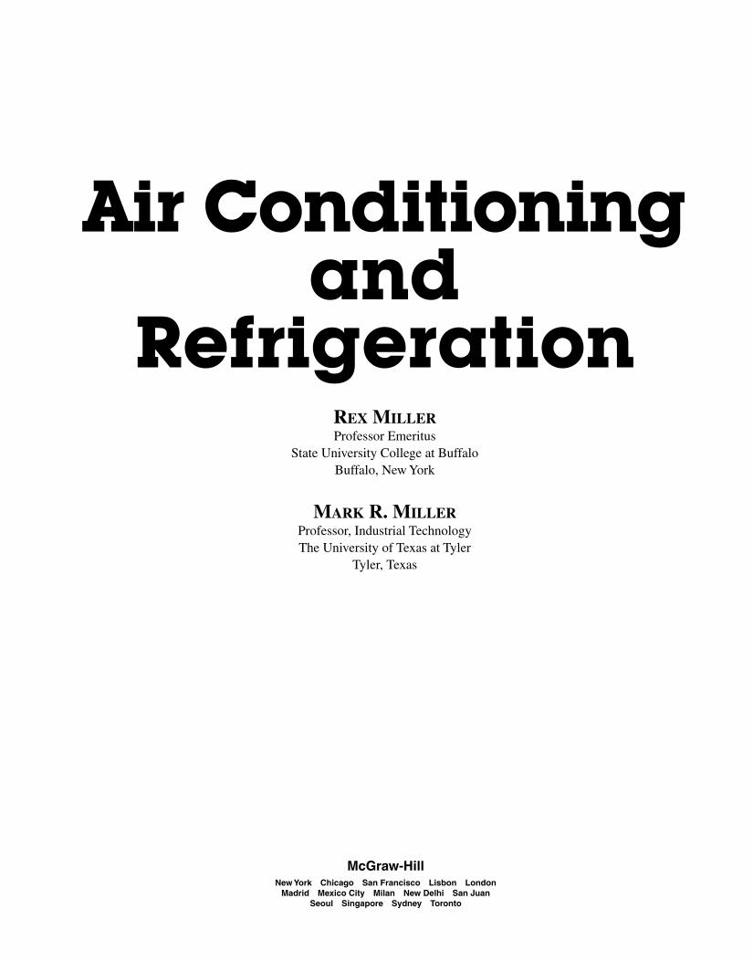
The greatest error in the use of the glass ther-mometer is that it is often not read in place. It is re-moved from the outlet grille of a packaged airconditioner. Then it is carried to eye level in the roomat ambient temperatures. Here it is read a few seconds
to a minute later. It is read in a temperature differentfrom that in which it was measured.
A liquid bath temperature reading is taken with thebulb in the bath. It is then left for a few minutes, im-mersed, and raised so that it can be read.
14 Air-Conditioning and Refrigeration Tools and Instruments
Fig. 1-27 Thermometers used to measure superheat. (Marsh)
Miller_CH01.qxd 3/1/06 10:20 AM Page 14

is always rough handling. Such handling cannot beavoided at all times in service work. Splitting does notoccur in thermometers that do not have a gas atmos-phere over the mercury. Such thermometers allow themercury to move back and forth by gravity, as well astemperature change. Such thermometers may not beused in other than vertical positions.
A split thermometer can be repaired. Most servicethermometers have the mercury reservoir at the bottomof the tube. In this case, cool the thermometer bulb inshaved ice. This draws the mercury to the lower part ofthe reservoir. Add more ice or salt to lower the tem-perature, if necessary. With the thermometer in an up-right position, tap the bottom of the bulb on a paddedpiece of paper or cloth. The entrapped gas causing thesplit column should then rise to the top of the mercury.After the column has been joined, test the service ther-mometer against a standard thermometer. Do this atseveral service temperatures.
Bimetallic ThermometersDial thermometers are actuated by bimetallic coils,mercury, vapor pressure, or gas. They are available invaried forms that allow the dial to be used in a numberof locations. See Fig. 1-29. The sensing portion of theinstrument may be located somewhere else. The dialcan be read in a convenient location.
Bimetallic thermometers have a linear dial face.There are equal increments throughout any given dialranges. Dial ranges are also available to meet highertemperature measuring needs. Ranges up to 1000°F(537.8°C) are available. In four selected ranges, dialsgiving both Celsius and Fahrenheit readings are avail-able. Bimetallic thermometers are economical. Thereis no need for a machined movement or gearing. Thetemperature-sensitive bimetallic element is connecteddirectly to the pointer. This type of thermometry is welladapted to measuring the temperature of a surface.Dome-mounted thermal protectors actually react to thesurface temperature of the compressor skin. Thesethermometers are used where direct readings need tobe taken, such as on:
• Pipelines
• Tanks
• Ovens
• Ducts
• Sterilizers
• Heat exchangers
• Laboratory temperature baths
A simple rule helps eliminate incorrect readings:
• Read glass thermometers while they are actually incontact with the medium being measured.
• If a thermometer must be handled, do so with as littlehand contact as possible. Read the thermometer im-mediately!
A recurring problem with mercury-filled glassthermometers is separation of the mercury column. SeeFig. 1-28. This results in what is frequently termed as asplit thermometer. The cause of the column’s splitting
Thermometers 15
Fig. 1-28 Mercury thermometer. (Weksler)
Miller_CH01.qxd 3/1/06 10:20 AM Page 15

The simplest type of dial thermometer is a stem.The stem is inserted into the medium to be mea-sured. With the stem immersed 2 in. in liquids and 4 in.in gases, this thermometer gives reasonably accuratereadings.
Although dial thermometers have many uses, thereare some limitations. They are not as universally ap-plicable as the simple glass thermometer. When order-ing a dial thermometer, specify the stem length, scalerange, and medium in which it will be used.
One of the advantages of bimetallic thermometryis that the thermometer can be applied directly to sur-faces. It can be designed to take temperatures of pipesfrom 0.5 through 2 in.
In operation, the bimetallic spiral is closely cou-pled to the heated surface that is to be measured. Thethermometer is held fast by two permanent magnets.One manufacturer claims their type of thermometerreaches stability within 3 min. Its accuracy is said to beplus or minus 2 percent in working ranges.
A simple and inexpensive type of bimetallic ther-mometer scribes temperature travel on a load of food in
transit. It can be used also to check temperature varia-tions in controlled industrial areas. The replacementchart gives a permanent record of temperature varia-tions during the test period.
Bimetallic drives are also used in control devices.For example, thermal overload sensors for motors andother electrical devices use bimetallic elements. Otherexamples will be discussed later.
Thermocouple ThermometersThermocouples are made of two dissimilar metals.Once the metals are heated, they give off an EMF(electromotive force or voltage). This electrical energycan be measured with a standard type of meter de-signed to measure small amounts of current. The metercan be calibrated in degrees, instead of amperes, mil-liamperes, or microamperes.
In use, the thermocouples are placed in themedium that is to be measured. Extension wires runfrom the thermocouple to the meter. The meter thengives the temperature reading at the remote location.
The extension wires may be run outside closedchests and rooms. There is no difficulty in closing a door,and the wires will not be pinches. On air-conditioningwork, one thermocouple may be placed in the supplygrille and another in the return grille. Readings can betaken seconds apart without handling a thermometer.
Thermocouples are easily taped onto the surface ofpipes to check the inside temperature. It is a good idea toinsulate the thermocouple from ambient and radiatedheat. Although this type of thermometer is rugged, itshould be handled with care. It should not be handledroughly. Thermocouples should be protected form corro-sive chemicals and fumes. Manufacturer’s instructionsfor protection and use are supplied with the instrument.
Resistance ThermometersOne of the newer ways to check temperature is with athermometer that uses a resistance- sending element. Anelectrical sensing unit may be made of a thermistor. Athermistor is a piece of material that changes resistancerapidly when subjected to temperature changes. Whenheated, the thermistor lowers its resistance. This de-crease in resistance makes a circuit increase its current.A meter can be inserted in the circuit. The change in cur-rent can be calibrated against a standard thermometer.The scale can be marked to read temperature in degreesCelsius or degrees Fahrenheit.
Another type of resistance thermometer indi-cates the temperature by an indicating light. The
16 Air-Conditioning and Refrigeration Tools and Instruments
Fig. 1-29 Dial-type thermometer. (Weksler)
Miller_CH01.qxd 3/1/06 10:20 AM Page 16
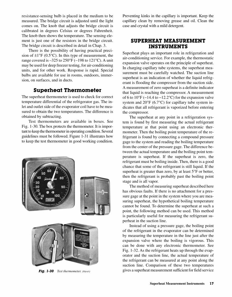
Preventing kinks in the capillary is important. Keep thecapillary clean by removing grease and oil. Clean thecase and crystal with a mild detergent.
SUPERHEAT MEASUREMENTINSTRUMENTS
Superheat plays an important role in refrigeration andair-conditioning service. For example, the thermostaticexpansion valve operates on the principle of superheat.In charging capillary tube systems, the superheat mea-surement must be carefully watched. The suction linesuperheat is an indication of whether the liquid refrig-erant is flooding the compressor from the suction side.A measurement of zero superheat is a definite indicatorthat liquid is reaching the compressor. A measurementof 6 to 10°F (−14.4 to −12.2°C) for the expansion valvesystem and 20°F (6.7°C) for capillary tube system in-dicates that all refrigerant is vaporized before enteringthe compressor.
The superheat at any point in a refrigeration sys-tem is found by first measuring the actual refrigeranttemperature at that point using an electronic ther-mometer. Then the boiling point temperature of the re-frigerant is found by connecting a compound pressuregage to the system and reading the boiling temperaturefrom the center of the pressure gage. The difference be-tween the actual temperature and the boiling point tem-perature is superheat. If the superheat is zero, therefrigerant must be boiling inside. Then, there is a goodchance that some of the refrigerant is still liquid. If thesuperheat is greater than zero, by at least 5°F or better,then the refrigerant is probably past the boiling pointstage and is all vapor.
The method of measuring superheat described herehas obvious faults. If there is no attachment for a pres-sure gage at the point in the system where you are mea-suring superheat, the hypothetical boiling temperaturecannot be found. To determine the superheat at such apoint, the following method can be used. This methodis particularly useful for measuring the refrigerant su-perheat in the suction line.
Instead of using a pressure gage, the boiling pointof the refrigerant in the evaporator can be determinedby measuring the temperature in the line just after theexpansion valve where the boiling is vigorous. Thiscan be done with any electronic thermometer. SeeFig. 1-32. As the refrigerant heats up through the evap-orator and the suction line, the actual temperature ofthe refrigerant can be measured at any point along thesuction line. Comparison of these two temperaturesgives a superheat measurement sufficient for field service
resistance-sensing bulb is placed in the medium to bemeasured. The bridge circuit is adjusted until the lightcomes on. The knob that adjusts the bridge circuit iscalibrated in degrees Celsius or degrees Fahrenheit.The knob then shows the temperature. The sensing ele-ment is just one of the resistors in the bridge circuit.The bridge circuit is described in detail in Chap. 3.
There is the possibility of having practical preci-sion of ±1°F (0.5°C). In this type of measurement, therange covered is –325 to 250°F (−198 to 121°C). A unitmay be used for deep freezer testing, for air-conditioningunits, and for other work. Response is rapid. Specialbulbs are available for use in rooms, outdoors, immer-sion, on surfaces, and in ducts.
Superheat ThermometerThe superheat thermometer is used to check for correcttemperature differential of the refrigerator gas. The in-let and outlet side of the evaporator coil have to be mea-sured to obtain the two temperatures. The difference isobtained by subtracting.
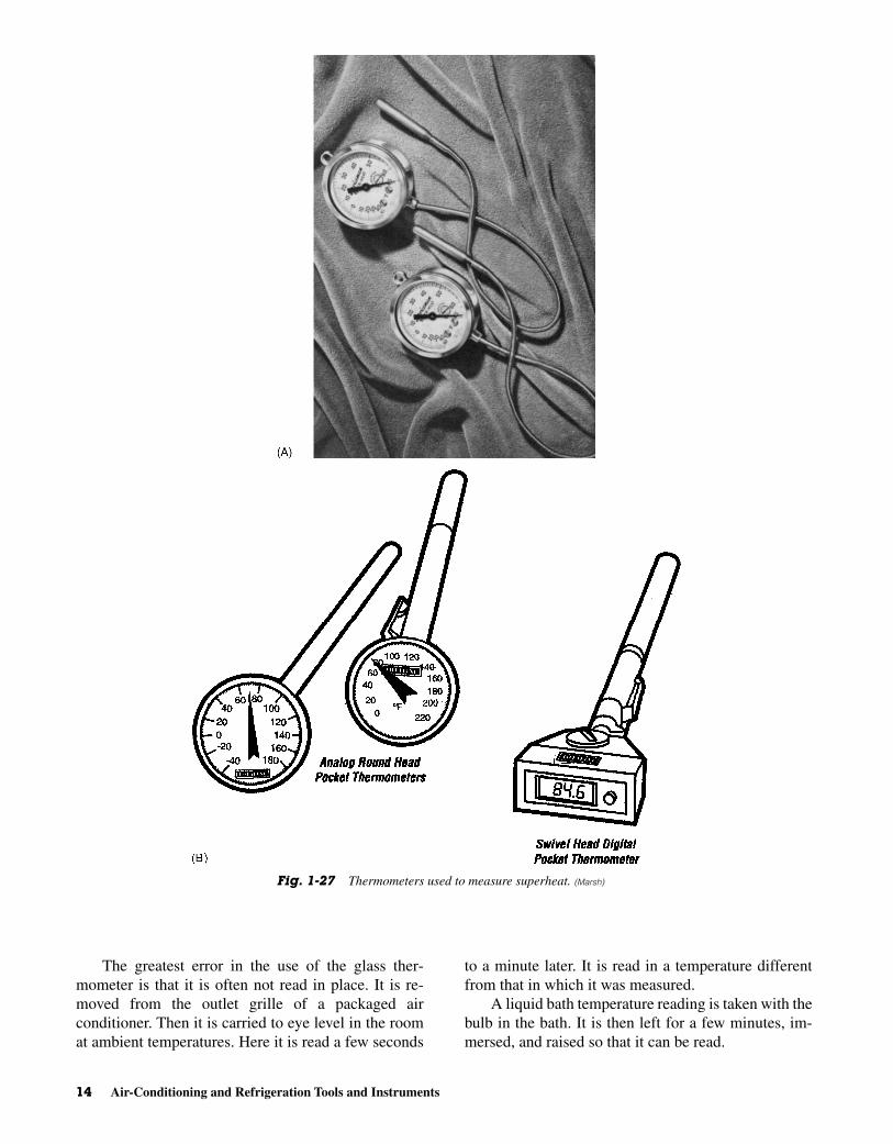
Test thermometers are available in boxes. SeeFig. 1-30. The box protects the thermometer. It is impor-tant to keep the thermometer in operating condition. Severalguidelines must be followed. Figure 1-31 illustrates howto keep the test thermometer in good working condition.
Superheat Measurement Instruments 17
Fig. 1-30 Test thermometer. (Marsh)
Miller_CH01.qxd 3/1/06 10:20 AM Page 17
18 Air-Conditioning and Refrigeration Tools and Instruments
Fig. 1-31 How to take care of the thermometer? (Marsh)
Miller_CH01.qxd 3/1/06 10:20 AM Page 18

unless a distributor-metering device is used or theevaporator is very large with a great amount of pres-sure drop across the evaporator.
By using the meter shown in Fig. 1-33, it is pos-sible to read superheat directly, using the tempera-ture differential feature. Strap one end of thedifferential probe to the outlet of the metering de-vice. Strap the other end to the point on the suctionline where the superheat measure is to be taken.Turn the meter to temperature differential and thesuperheat will be directly read on the meter.
Figure 1-34 illustrates the way superheat works.The bulb “opening” force (F-l) is caused by bulbtemperature. This force is balanced against the sys-tem back-pressure (F-2) and the valve spring force(F-3). The force holds the evaporator pressurewithin a range that will vaporize the entire refriger-ant just before it reaches the upper part or end of theevaporator.
The method of checking superheat is shown inFig. 1-35. The procedure is as follows:
Superheat Measurement Instruments 19
Fig. 1-32 Hand-held electronic thermometer. (Amprobe)
Fig. 1-33 Electronic thermometer for measuring superheat. The probes are made ofthermo-couple wire. They can be strapped on anywhere with total contact with the sur-face. This thermometer covers temperatures from –50° to 1500°F on four scales. Thetemperature difference between any two points directly means it can read superheat di-rectly. It is battery operated and has a ±2 percent accuracy on all ranges. Celsius scalesare available. (Thermal Engineering)
Miller_CH01.qxd 3/1/06 10:20 AM Page 19

1. Measure the temperature of the suction line at thebulb location. In the example, the temperature is37°F.
2. Measure the suction line pressure. In the example,the suction line pressure is 27 psi.
3. Convert the suction line pressure to the equivalentsaturated (or liquid) evaporator temperature by us-ing a standard temperature-pressure chart (27 psi =28°F).
4. Subtract the two temperatures. The difference is su-perheat. In this case, superheat is found by the for-mula: 37°F – 28°F = 9°F
Suction pressure at the bulb may be obtained by ei-ther of the following methods:
• If the valve has an external equalizer line, the gage inthis line may be read directly.
• If the valve is internally equalized, take a pressuregage reading at the compressor base valve. Add tothis the estimated pressure drop between the gageand the bulb location. The sum will approximate thepressure at the bulb.
20 Air-Conditioning and Refrigeration Tools and Instruments
Fig. 1-34 How superheat works. (Parker-Hannefin)
Fig. 1-35 Where and how to check superheat? (Parker-Hannefin)
Miller_CH01.qxd 3/1/06 10:20 AM Page 20

The system should be operating normally whenthe superheat is between 6 and 10°F (−14.4 and−12.2°C).
HALIDE LEAK DETECTORSNot too long ago leaks were detected by using soapbubbles and water. If possible, the area of the suspectedleak was submerged in soap water. Bubbles pinpointedthe leak area. If the unit or suspected area was not eas-ily submerged in water then it was coated with soap so-lution. In addition, where the leak was covered withsoap, bubbles would be produced. These indicated thelocation of the leak. These methods are still used todayin some cases. However, it is now possible to obtainbetter indications of leaks with electronic equipmentwith halide leak detectors.
Halide leak detectors are used in the refrigerationand air-conditioning industry. They are designed for lo-cating leaks and noncombustible halide refrigerantgases. See Figs. 1-36 and 1-37.
The supersensitive detector will detect the pres-ence of as little as 20 parts per million of refrigerantgases. See Fig. 1-38. Another model will detect 100parts of halide gas per million parts of air.
Setting UpThe leak detector is normally used with a standardtorch handle. The torch handle has a shut-off valve.Acetylene can be supplied by a “B” tank (40 ft3) or MCtank (10 ft3). In either case, the tank must be equippedwith a pressure-reducing regulator; the torch handle isconnected to the regulator by a suitable length of fittedacetylene hose. See Fig. 1-36.
Halide Leak Detectors 21
Fig. 1-37 Halide leak detector for use with an MC tank. (Union
Carbide)
Fig. 1-38 Detectors. (A) Supersensitive detector of refrigerantgases. This detects 20 parts per million. (B) Standard model detec-tor torch. This detects 100 parts per million. (Union Carbide)
Fig. 1-36 Halide leak detector for use with a B tank. (Union
Carbide)
Miller_CH01.qxd 3/1/06 10:20 AM Page 21

An alternate setup uses an adapter to connectthe leak detector stem to an MC tank. No regulator isrequired. The tank must be fitted with a handle. SeeFig. 1-37.
In making either setup, be sure all seating sourcesare clean before assembling. Tighten all connectionssecurely. Use a wrench to tighten hose and regulatorconnections. If you use the “B” tank setup, be sure tofollow the instructions supplied with the torch handleand regulator.
LightingSetup with tank, regulator, and torch handle. Refer toFig. 1-36.
• Open the tank valve one-quarter turn, using a P-O-Ltank key.
• Be sure the shut-off valve on the torch handle isclosed. Then, adjust the regulator to deliver 10 psi. Dothis by turning in the pressure-adjusting screw untilthe “C” marking on the flat surfaces of the screw isopposite the face of the front cap. Test for leaks.
• Open the torch handle shut-off valve and light thegas above the reaction plate. Use a match or taper.
• Adjust the torch until a steady flame is obtained.
Setup with MC tank and adaptor. Refer to Fig. 1-37.
• With the needle valve on the adaptor closed tightly,just barely open the tank valve, using a P-O-L tankkey. Test for leaks.
• Open the adapter needle valve about one-quarterturn. Light the gas above the reaction plate. Use amatch or taper.
Leak Testing the SetupUsing a small brush, apply a thick solution of soap andwater to test for leaks. Check for leaks at the regulatorand any connection point. Check the hose to handleconnection, hose to regulator connection, and regula-tor or adaptor connection. If you find a leak, correct itbefore you light the gas. A leak at the valve stem of asmall acetylene tank can often be corrected by tighten-ing the packing nut with a wrench. If this will not stopa leak, remove the tank. Tag it to indicate valve stemleakage. Place it outdoors in a safe spot until you canreturn it to the supplier.
Adjusting the FlamePlace the inlet end of the suction hose so that it isunlikely to draw in air to contaminate the refrigerant
vapor. Adjust the needle valve on the adapter or torchhandle until the pale blue outer envelope of the flameextends about 1 in. above the reaction plate. The innercone of the flame, which should also be visible abovethe reaction plate, should be clear and sharply defined.
If the outer envelope of the flame, when of properlength, is yellow, not pale blue, the hose is picking uprefrigerant vapors. There may also be some obstructionin the suction hose. Make sure the suction tube is notclogged or bent sharply. If the suction tube is clear,shut off the flame. Close the tank valve. Disconnect theleak detector from the handle or adaptor. Check for dirtin the filter screw or mixer disc. See Fig. 1-39. Usea 1/8 in. socket key (Allen wrench) to remove or replacethe filter screw. This screw retains the mixer disc.
Detecting LeaksTo explore the leaks, move the end of the suction hosearound all points where there might be leaks. Be care-ful not to kink the suction hose.
Watch for color changes in the flame as you movethe end of the suction hose:
• With the model that has a large opening in the flameshield (wings on each side), a small leak will changethe color of the outer flame to a yellow or an orange-yellow hue. As the concentration of halide gas in-creases, the yellow will disappear. The lower part ofthe flame will become a bright, light blue. The top ofthe flame will become a vivid purplish blue.
• With the model that has no wings alongside theflame shield opening, small concentrations of halidegas will change the color. A bright blue-green outerflame indicates a leak. As the concentration of thehalide gas increases, the lower part of the flame willlose its greenish tinge. The upper portion will be-come a vivid purplish blue.
• Watch for color intensity changes. The location ofsmall color leaks can be pinpointed rapidly. Color inthe flame will disappear almost instantly after the in-take end of the hose has passed the point of leakage.With larger leaks, you will have to judge the point ofleakage. Note the color change from yellow to purple-blue or blue-green to blue-purple, depending on themodel used.
MaintenanceWith intensive usage, an oxide scale may form on thesurface of the reaction plate. Thus, sensitivity is re-duced. Usually this scale can be easily broken awayfrom the late surface. If you suspect a loss in sensitivity,
22 Air-Conditioning and Refrigeration Tools and Instruments
Miller_CH01.qxd 3/1/06 10:20 AM Page 22

AmmeterThe ammeter is used to measure current. It can mea-sure the amount of current flowing in a circuit. It mayuse one of a number of different basic meter move-ments to accomplish this. The most frequently used ofthe basic meter movements is the D’Arsonval type.See Fig. 1-40. It uses a permanent magnet and an elec-tromagnet to determine circuit current. The permanentmagnet is used as a standard basic source of magnet-ism. As the current flows through the coil of wire, itcreates a magnetic field around it. This magnetic fieldis strong or weak, depending upon the amount of cur-rent flowing through it. The stronger the magneticfield created by the moving coil, the more it is repelledby the permanent magnet. This repelling motion is cal-ibrated to read amperes, milliamperes (0.001 A), ormicroamperes (0.000001 A).
The D’Arsonval meter movement may also beused on AC when a diode is placed in series with themoving coil winding. The diode changes the AC to DCand the meter works as on DC. See Fig. 1-41. The dialor face of the instrument is calibrated to indicate theAC readings.
There are other types of AC ammeters. They arenot always as accurate as the D’Arsonval, but theyare effective. In some moving magnet meters, the coil
remove the reaction plate. Scrape its surface with aknife or screwdriver blade, or install a new plate.
ELECTRICAL INSTRUMENTSSeveral electrical instruments are used by the air-conditioning serviceperson to see if the equipment isworking properly. Studies show that the most troublecalls on heating and cooling equipment are electricalin nature.
The most frequently measured quantities arevolts, amperes, and ohms. In some cases, wattage ismeasured to check for shorts and other malfunctions.A wattage meter is available. However, it must beused to measure volt-amperes (VA) instead of watts.To measure watts, it is necessary to use DC only orconvert the VA to watts by using the power factor.The power factor times the volt-amperes producesthe actual power consumed in watts. Since most cool-ing equipment use AC, it is necessary to convert towatts by this method.
A number of factors can be checked with electricalinstruments. For example, electrical instruments canbe used to check the flow rate from a centrifugal waterpump, the condition of a capacitor, or the character ofa start or run winding of an electric motor.
Electrical Instruments 23
Fig. 1-39 Position of filter screw and mixer disc on Prest-O-Lite halide leak detector (A) Stan-dard model. (B) Supersensitive model.
Miller_CH01.qxd 3/1/06 10:20 AM Page 23

is stationary and the magnet moves. Althoughrugged, this type is not as accurate as the D’Arsonvaltype meter.
The moving vane meter is useful in measuring cur-rent when AC is used. See Fig. 1-42.
The clamp-on ammeter has already been dis-cussed. It has some limitations. However, it does haveone advantage in that it can be used without having to
break the line to insert it. Most ammeters must be con-nected in series with the consuming device. Thatmeans one line has to be broken or disconnected to in-sert the meter into the circuit.
The ampere reading can be used to determine ifthe unit is drawing too much current or insufficientcurrent. The correct current amount is usually stampedon the nameplate of the motor or the compressor.
Starting and running amperes may be checked tosee if the motor is operating with too much load or itis shorted. The flow rate of some pumps can be deter-mined by reading the current the motor pulls. Theload on the entire line can be checked by inserting theammeter in the line. This is done by taking out thefuse and completing the circuit with the meter. Becareful.
If the ammeter has more than one range, it is bestto start on the highest range and work down. The read-ing should be in or near the center of the meter scalefor a more accurate reading. Make sure you have someidea what the current in the circuit should be before in-serting the meter. Thus, the correct range—or, in someinstances, the correct meter—can be selected.
24 Air-Conditioning and Refrigeration Tools and Instruments
Fig. 1-40 Moving coil (D’Arsonval) meter movement.
Fig. 1-41 Diode inserted in the circuit with a D’Arsonval move-ment to produce an AC ammeter.
Miller_CH01.qxd 3/1/06 10:20 AM Page 24

VoltmeterThe voltmeter is used to measure voltage. Voltage isthe electrical pressure needed to cause current to flow.The voltmeter is used across the line or across a motoror whatever is being used as a consuming device.
Voltmeters are nothing more than ammeters thatare calibrated to read volts. There is, however, an im-portant difference. The voltmeter has a very high inter-nal resistance. That means very small amounts ofcurrent flow through its coil. See Fig. 1-43. This highresistance is produced by multipliers. Each range onthe voltmeter has a different resistor to increase the re-sistance so the line current will not be diverted throughit. See Fig. 1-44. The voltmeter is placed across theline, whereas the ammeter is placed in series. You donot have to break the line to use the voltmeter. Thevoltmeter has two leads. If you are measuring DC, youhave to observe polarity. The red lead is the positive (+)
Electrical Instruments 25
Fig. 1-42 Air-damping system used in the moving-vane meter.
Fig. 1-43 An ammeter with high resistance in series with themeter movement allow it to measure voltage.
Miller_CH01.qxd 3/1/06 10:20 AM Page 25

and the black lead is the negative (−). However, whenAC is used, it does not matter which lead is placed onwhich terminal. Using a D’Arsonval meter movement,voltmeters can be made with the proper diode tochange AC to DC. Voltmeters can be made with a sta-tionary coil and a moving magnet. Others types of volt-meters are available. They use various means ofregistering voltage.
If the voltage is not known, use the highest scale onthe meter. Turn the range switch to appoint where thereading is in the midrange of the meter movement.
Normal line voltage in most locations is 120 V.When the line voltage is lower than normal, it is possiblefor the equipment to draw excessive current. This willcause overheating and eventual failure and/or burnout.The correct voltage is needed for the equipment to oper-ate according to its designed specifications. The voltagerange is usually stamped on the nameplate of the device.Some will state 208 V. This voltage is obtained from athree-phase connection. Most home or residential volt-age is supplied at 120 V or 230 V. The range is 220 to240 V for normal residential service. The size of the wireused to connect the equipment to the line is important. Ifthe wire is too small, voltage will drop. There will below voltage at the consuming device. For this reason acertified electrician with knowledge of the NEC shouldwire a new installation.
OhmmeterThe ohmmeter measures resistance. The basic unit ofresistance is the ohm (Ω). Every device has resistance.That is why it is necessary to know the proper resis-tance before trying to troubleshoot a device by using anohmmeter. The ohmmeter has its own power supply.See Fig. 1-45. Do not use an ohmmeter on a line that
is energized or connected to a power source of anyvoltage.
An ohmmeter can read the resistance of the wind-ings of a motor. If the correct reading has been given bythe manufacturer, it is then possible to see if the read-ing has changed. If the reading is much lower, it mayindicate a shorted winding. If the reading is infinite(w), it may mean there is a loose connection or an opencircuit.
Ohmmeters have ranges. Figure 1-46 shows a me-ter scale. The R × 1 range means the scale is read as is.If the R × 10 range is used, it means that the scale read-ing must be multiplied by 10. If the R × 1000 range isselected, then the scale reading must be multiplied by1000. If the meter has a R × 1 meg range, the scalereading must be multiplied by one million. A meg isone million.
Multimeter The multimeter is a combination of meters. See Fig. 1-47.It may have a voltmeter, an ammeter, and an ohmmeter
26 Air-Conditioning and Refrigeration Tools and Instruments
Fig. 1-44 Different types of multirange voltmeters. This viewshows the interior of the meter box or unit.
Fig. 1-45 Internal circuit of an ohmmeter.
Fig. 1-46 A multimeter scale. Note the ohms and volt scales.
Miller_CH01.qxd 3/1/06 10:20 AM Page 26

action of the two magnetic fields, the current is mul-tiplied by the voltage. Wattage is read on the meterscale.
The volt-ampere is the unit used to measure voltstime amperes in an AC circuit. If a device has induc-tance (as in a motor) or capacitance (some motors haverun-capacitors), the true wattage is not given on awattmeter. The reading is in volt-amperes instead ofwatts. It is converted to watts by multiplying the read-ing by the power factor. A wattmeter reads watts onlywhen it is connected to a DC circuit or to an AC circuitwith resistance only.
The power factor is the ratio of true power to appar-ent power. Apparent power is what is read on awattmeter on an AC line. True power is the wattage read-ing of DC. The two can be used to find the power factor.The power factor is the cosine of the phase angle. Thepower factor can be found by using a mathematical com-putation or a very delicate meter designed for the pur-pose. However, the power factor of equipment usingalternating current is usually stamped on the nameplateof the compressor, the motor, or the unit itself.
Wattmeters are also used to test capacitors. Somecompanies provide charts to convert wattage ratings tomicrofarad ratings. The wattmeter can test the actualconnection of the capacitor. The ohmmeter tells if thecapacitor is good or bad. However, it is hard to indicatehow a capacitor will function in a circuit with the
in the same case. This is the usual arrangement forfieldwork. This way it is possible to have all three me-ters in one portable combination. It should be checkedfor each of the functions.
The snap-around meter uses its scale for a numberof applications. It can be read current by snappingaround the current carrying wire. If the leads are used,it can be used as a voltmeter or an ohmmeter. Remem-ber that the power must be off to use the ohmmeter.This meter is mounted in its own case. It should be pro-tected from shock and vibration just as any other sensi-tive instrument.
WattmeterThe wattmeter is used to measure watts. However,when used on an AC line it measures volt-amperes.If watts are to be measured, the reading must be con-verted to watts mathematically. Multiply the readingon the wattmeter by the power factor (usually avail-able on the nameplate) to obtain the reading in watts.
Wattmeters use the current and the voltage con-nections as with individual meters. See Fig. 1-48.One coil is heavy wire and is connected in series. Itmeasures the current. The other connection is madein the same way as with the voltmeter and con-nected across the line. This coil is made of manyturns of fine wire. It measures the voltage. By the
Electrical Instruments 27
Fig. 1-47 Two types of multimeters.
Miller_CH01.qxd 3/1/06 10:20 AM Page 27

voltage applied. This is why testing with the wattmeteris preferred.
OTHER INSTRUMENTSMany types of meters and gages are available to test al-most any quantity or condition. For example:
• Air–filter efficiency gages
• Air-measurement gages
• Humidity-measuring devices
• Moisture analyzers
• British thermal unit (Btu) meters
Vibration and sound meters and recorders are alsoavailable.
Air–Filter Efficiency GagesAir measurements are taken in an air-distribution sys-tem. They often reveal the existence and location of un-intentionally closed or open dampers and obstructions.Leaks in the ductwork and sharp bends are located thisway.
Air measurements frequently show the existence of ablocked filter. Dirty and blocked filters can upset the bal-ance of either a heating or cooling system. This is impor-tant whether it is in the home or in a large building.
Certain indicators and gages can be mounted in airplenums. They can be used to show that the filter hasreached a point where it is restricting the airflow. Anair plenum is a large space above the furnace heating orcooling unit.
Air-Measurement InstrumentsThe volume and velocity of air are important measure-ments in the temperature control industries. Properamounts of air are indispensable to the best functioningof refrigeration cycles, regardless of the size of the sys-tem. Air-conditioning units and systems also rely uponvolume and velocity for proper distribution of condi-tioned air.
Only a small number of contractors are equippedto measure volume and velocity correctly. The compa-nies that are doing the job properly are in great de-mand. Professional handling of air volume andvelocity ensures the efficient use of equipment. Largebuildings are very much in need of the skills of air-balancing teams.
Some people attempt to obtain proper airflow bymeasuring air temperature. They adjust dampers andblowers speeds. However, they usually fail in their at-tempts to balance the airflow properly.
There are instruments available to measure air ve-locity and volume. Such instruments can accurately
28 Air-Conditioning and Refrigeration Tools and Instruments
Fig. 1-48 (A) Wattmeter connection for measuring input power. (B) Alternatewattmeter connection. (C) With load disconnected, uncompensated wattmeter measuresits own power loss.
Miller_CH01.qxd 3/1/06 10:20 AM Page 28

Thin-film sensors are now available, which use anabsorbent deposited on a silicon substrate such that theresistance or capacitance varies with relative humidity.They are quite accurate in the range of ±3 to 5 percent.They also have low maintenance requirements.
Stationary Psychrometers Stationary psychrome-ters take the same measurements as sling psychrome-ters. They do not move. However, they use a blower orfan to move the air over the thermometer bulbs.
For approximate rh readings, there are metered de-vices. They are used on desks and walls. They are notaccurate enough to be used in engineering work
Humidistats, which are humidity controls, are usedto control humidifiers. They operate the same way asthermometers in closing contacts to complete a circuit.They do not use the same sensing element, however.
Moisture Analyzers It is sometimes necessary toknow the percentage of water in a refrigerant. The wa-ter vapor or moisture is measured in parts per million.The necessary measuring instrument is still used pri-marily in the laboratory. Instruments for measuring hu-midity are not used here.
Btu Meters The Btu is used to indicate the amountof heat present. Meters are especially designed to indi-cate the Btu in a chilled water line, a hot water line, ora natural gas line. Specially designed, they are used byskilled laboratory personnel at present.
Vibration and Sound MetersMore cities are now prohibiting conditioning unitsthat make too much noise. In most cases, vibration isthe main problem. However, it is not an easy task tolocate the source of vibration. However, special me-ters have been designed to aid in the search for vibra-tion noise.
Portable noise meters are available. The dB, ordecibel, is the unit for the measurement of sound. Thereare a couple of bands on the noise meters. The dB-Ascale corresponds roughly to the human hearing range.Other scales are available for special applications.
More emphasis is now being placed on noise levelsin factories, offices, and schools. The OccupationalSafety and Hazards Act (OSHA) lays down strictguidelines regarding noise levels. There are penaltiesfor noncompliance. Thus, it will be necessary for allnew and previously installed units to be checked fornoise.
High-velocity air systems—used in large buildings—are engineered to reduce noise to levels set by theOSHA. For example, there are chambers to lower the
measure the low pressures and differentials involved inair distribution.
Draft gages do measure pressure. However, theirspecific application to air control makes it more appro-priate to discuss them here, rather than under pressuregages. They measure pressure in inches of water. Theycome in several styles. The most familiar is the slantedtype. It may be used either in the field or in the shop.
Meter type draft gages are better for fieldwork.They can be carried easily. They can sample air at var-ious locations, with the meter box in one location.
Besides air pressure, it is frequently necessary tomeasure air volume, which is measured in cubic feetper minute or cfm. Air velocity is measured in feet perminute or fpm. The measure of airflow is still some-what difficult. However, newer instruments are mak-ing accurate measurements possible.
Humidity-MeasurementInstruments
Many hygroscopic (moisture absorbing) materials canbe used as relative-humidity sensors. Such materialsabsorb or lose moisture until a balance is reached withthe surrounding air. A change in material moisturecontent causes a dimensional change, and this changecan be used as an input signal to a controller. Com-monly used materials include:
• Human hair
• Wood
• Biwood combinations similar in action to a bimetal-lic temperature sensor
• Organic films
• Some fabrics, especially certain synthetic fabrics
All these have the drawbacks of slow response andlarge hysteresis effects. Accuracy also tends to bequestionable unless they are frequently calibrated.Field calibration of humidity sensors is difficult.
Humidity is read in rh or relative humidity. To ob-tain the rh, it is necessary to use two thermometers.One thermometer is a dry bulb, the other is a wet bulb.The device used to measure rh is the sling psychrome-ter. It has two glass-stem thermometers. The wet bulbthermometer is moistened by a wick attached to thebulb. As the dual thermometers are whirled, air passesover them. The dry and wet bulb temperatures arerecorded. Relative humidity is determined by:
• Graphs
• Slide rules
• Similar devices
Other Instruments 29
Miller_CH01.qxd 3/1/06 10:20 AM Page 29

noise in the ducts. Air engineers are constantly work-ing on high-velocity systems to try to solve some of theproblems associated with them.
SERVICE TOOLSService personnel use some special devices to helpthem with repair jobs in the field. One of them is thechaser kit. See Fig. 1-49. It is used for cleaning par-tially plugged capillary tubes. The unit includes 10spools of lead alloy wire. These wires can be used aschasers for the 10 most popular sizes of capillary tubes.In addition to the wire, a cap tube gage, a set of sizingtools, and a combination file/reamer are included in themetal case. This kit is used in conjunction with the Cap-Check. The Cap-Check is a portable, self-contained hy-draulic power unit with auxiliary equipment especiallyadapted to cleansing refrigeration capillary tubes. SeeFig. 1-50. A small plug of wire from the chaser kit isinserted into the capillary tube. The wire is a few thou-sandths of an inch smaller than the internal diameter of
the capillary tube. This wire is pushed like a pistonthrough the capillary tube with hydraulic pressure fromthe Cap-Check. A 0 to 5000 psi gage shows pressurebuildup if the capillary tube is restricted. It also showswhen the chaser has passed through the tube. A trigger-operated gage shutoff is provided so the gage will notbe damaged if pressure greater than 5000 psi is desired.When the piston stops against a partial restriction,high-velocity oil is directed around the piston and againstthe wall, washing the restriction away and allowing thewire to move through the tube. The lead wire eventuallyends up in the bottom of the evaporator, where it remains.The capillary tube is then as clean as when it was orig-inally installed.
A 30 in. high-pressure hydraulic hose with a 1/4 in.Society of Automotive Engineers (SAE) male flare outletconnects the cap tube to the Cap-Check for simplehandling. An adapter comes with the Cap-Check forsimple handling. Another adapter comes with the unitto connect the cap tube directly to the hose outlet withouta flared fitting.
30 Air-Conditioning and Refrigeration Tools and Instruments
Fig. 1-49 Cap-Check chaser kit. This is a means to clean partially plugged capillarytubes. It has 10 spools of lead alloy wire. These wires can be used as a chaser for the 10most popular sizes of cap tubes. A cap tube gage, set of sizing tools, and a combinationfile/reamer are included in the kit.
Miller_CH01.qxd 3/1/06 10:20 AM Page 30

SPECIAL TOOLSEventually, almost every refrigerant-charging job turnsinto a vapor-charging job. Unless the compressor isturned on, liquid can be charged into the high side onlyso long before the system and cylinder pressures be-come unfavorable. Once that happens, all refrigerantmust be taken in the low side in the form of vapor.
Vapor charging is much slower than liquid charg-ing. To create a vapor inside the refrigerant cylinder,the liquid refrigerant must be boiling. Boiling refriger-ant absorbs heat. This is the principle on which refrig-eration operates.
The boiling refrigerant absorbs heat from the re-frigerant surrounding it in the cylinder. The net effect isthat the cylinder temperature begins to drop soon afteryou begin charging with vapor. As the temperaturedrops, the remaining refrigerant will not vaporize asreadily. Charging will be slower.
To speed charging, service personnel add heat tothe cylinder by immersing part of it in hot water. Thecylinder temperature rises. The boiling refrigerant be-comes vigorous and charging returns to a rapid rate. Itis not long, though, before all the heat has been takenfrom the water and more hot water must be added.
The Vizi-Vapr is an example of how a device canremove liquid from a cylinder and apply it to the sys-tem in the form of a vapor. See Fig. 1-52. No heat is re-quired. This eliminates the hazards of using a torch andhot water. The change from a liquid to a gas or vapor
The Cap-Gage is a capillary tube gage. It has 10stainless steel gages to measure the most popular sizesof capillary tubes. See Fig. 1-51.
More up to date tools and test equipment areshown in the Appendices. Go online to find the latestavailable tools and instruments. One source for toolsand test equipment is yellowjacket.com or the RitchieEngineering Company in Minnesota. Another is Mas-tercool.com in New Jersey.
Special Tools 31
Fig. 1-51 The Cap-Gage is a pocketknife-type cap tube gage with 10 stainless steelgages to measure the most popular sizes of cap tubes. (Thermal Engineering)
Fig. 1-50 Cap-Check is a portable self-contained hydraulicpower unit with auxiliary equipment that is especially adapted tocleaning refrigeration capillary tubes. It is hand operated.
Miller_CH01.qxd 3/1/06 10:20 AM Page 31

takes place in the Vizi-Vapr. It restricts the chargingline between the cylinder and compressor. This restric-tion is much like an expansion valve in that it maintainshigh cylinder pressure behind it to hold the refrigerantas a liquid.
However, it has a large pressure drop across it tostart evaporation. Heat required to vaporize refrigerantis taken from the air surrounding the unit, not from theremaining refrigerant. This produces a dense, saturatedvapor.
The amount of restriction in the unit is very criti-cal. Too much restriction will slow charging consider-ably. It also will allow liquid to go through and causeliquid slugging in the compressor. The restriction set-ting is different for each size system, for differenttypes of refrigerants and even for different ambienttemperatures.
VACUUM PUMPSUse of the vacuum pump may be the single most im-portant development in refrigeration and air-conditioningservicing. The purpose of a vacuum pump is to removethe undesirable materials that create pressure in a re-frigeration system. These include:
• Moisture
• Air (oxygen)
• Hydrochloric acid
In addition, there are other materials that will va-porize at low micron range. These, along with a widevariety of solid materials, are pulled into the vacuumpump in the same way a vacuum cleaner sucks updirt.
Evacuation is being routinely performed onalmost every service call on which recharging isrequired.
NOTE: It is no longer permitted to sim-ply add refrigerant to the system withone end open for evacuation into the at-mosphere. This shortcut was a favoriteof many service technicians over theyears since it was quick and the refrig-erant was inexpensive.
Vacuum levels formerly unheard of for field evac-uations are being accomplished daily by service per-sons who are knowledgeable regarding vacuumequipment. These service persons have found throughexperience that the two-stage pump is much better thanthe single-stage pump for deep evacuations. SeeFigs. 1-53 and 1-54. It was devised as a laboratory in-strument and with minor alterations; it has beenadapted to the refrigeration field. It is the proper toolfor vacuum evacuations in the field. The latest in vac-uum pumps is shown in Appendix 4.
32 Air-Conditioning and Refrigeration Tools and Instruments
Fig. 1-52 The Vizi-Vapr is a device that allows rapid charging of a compressor with-out heating the cylinder of refrigerant. (Thermal Engineering)
Miller_CH01.qxd 3/1/06 10:20 AM Page 32

ate a vacuum section and a pressure section inside thepump. The seal between the vacuum and the pressuresections is made by the vacuum pump oil. These sealsare the critical factor in the depth that a vacuum pumpcan pull. If the seals leak, the pump will not be able todraw a deep vacuum. Consequently, less gas can beprocessed. A pump with high leakage across the sealwill be able to pull a deep vacuum on a small system, butthe leakage will decrease the pumping speed (cfm) in the
To understand the advantages of a two-stage pumpover a single-stage pump refer to Fig. 1-55. This showsthe interior of a two-stage vacuum pump. This is a sim-plified version of a vacuum stage. It is built on the prin-ciple of a Wankel engine.
There is a stationary chamber with an eccentric ro-tor revolving inside. The sliding vanes pull gasesthrough the intake. They compress them and force theminto the atmosphere through the exhaust. The vanes cre-
Vacuum Pumps 33
Fig. 1-53 Single-stage portable vacuum pump. (Thermal Engineering)
Fig. 1-54 Dual or two-stage portable vacuum pump. (Thermal Engineering)
Miller_CH01.qxd 3/1/06 10:20 AM Page 33

deep vacuum region. Long pull-down times will result.There are three oil seals in a single-stage vacuum pump.Each seal must hold against a high pressure on one sideand a deep vacuum on the other side. This places a greatdeal of strain on the oil seal. A two-stage vacuum pumpcuts the pressure strain on the oil seal in half. Such apump uses two chambers instead of one to evacuate asystem. The first chamber is called the deep vacuumchamber. It pulls in the vacuum gases from the deep vac-uum and exhausts them into the second chamber at amoderate vacuum. The second chamber, or stage, bringsin these gases at a moderate vacuum and exhausts theminto the atmosphere. By doing this, the work of a singlechamber is split between two chambers. This, in turn,cuts in half the strain on each oil seal, which reduces theleakage up to 90 percent.
A two-stage vacuum pump is more effective than asingle-stage vacuum pump. For example, a single-stage vacuum pump rated for 1.5 cfm capacity will takeone and one-half hours to evacuate one drop of water.A two-stage vacuum pump with the same rating willevacuate the drop in 12 min.
For evacuation of a 5-ton system saturated withmoisture, a minimum of 15 h evacuation time is re-quired in using a single-stage vacuum pump. A two-stage pump with the same cfm rating could do the jobin as little as 2 h.
Another advantage of the two-stage pump is relia-bility. As you can see, if the oil seal is to be effective,the tolerances in these vacuum pumps must be veryclose between rotor and stator. If the tolerances are notcorrect, the oil seal will not be effective. Slippage oftolerance due to wear is the major cause of vacuumpump failure. With a single-stage pump, when the tol-erance is in the stage slips, the pump loses effective-
ness. With a two-stage pump, if one stage loses toler-ance, the other one will still pull the vacuum of a sin-gle-stage pump.
Larger cfm, two-stage vacuum pumps are pre-ferred to the single-stage vacuum pumps. The cost dif-ference between the two is not great. In addition, thetime saved by using the two-stage pump is evident onthe first evacuation.
Vacuum Pump MaintenanceThe purpose of vacuum pump oil is to lubricate thepump and act as a seal. To perform this function the oilmust have:
• A low vapor pressure that does not materially in-crease up to 125°F (51.7°C)
• A viscosity sufficiently low for use at 60°F (15.6°C)yet constant up to 125°F (51.7°C)
These requirements are easily met by using a lowvapor pressure, paraffin-based oil having a viscosity ofapproximately 300 SSU (shearing stress units) at100°F (37.8°C) and a viscosity index in the range of95 to 100. This type of uninhibited oil is readily ob-tainable. It is the material provided by virtually all sell-ers of vacuum pump oil to the refrigeration trade.
Vacuum Pump Oil ProblemsThe oils used in vacuum pumps are designed to lubricateand seal. Many of the oils available for other jobs are notdesigned to clean as they lubricate. Neither are they de-signed to keep in suspension the solids freed by thecleaning action of the oil. In addition, the oil is not usu-ally heavily inhibited against the action of oxygen.Therefore, the vacuum pump must be run with flushingoil periodically to clean it. Otherwise, its efficiency willbe reduced. The use of flushing oils is recommended bypump manufacturers.
If hydrochloric acid has been pulled into the pump,water, solids, and oil will bond together to form sludgeor slime that may be acidic. The oil also may deterioratedue to oxidation (action on the oil by oxygen in airpulled through the pump). This results in a pump thatwill not pull a proper vacuum, may wear excessively, se-riously corrode, or rust internally.
Operating InstructionsUse vacuum-pump oil in the pump when new. After 5to 10 h of running time, change the oil. Make sure all ofthe original oil is removed from the pump. Thereafter,change the oil after every 30 h of operation when theoil becomes dark due to suspended solids drawn into
34 Air-Conditioning and Refrigeration Tools and Instruments
Fig. 1-55 Two-stage vacuum pump showing seals and intake,exhaust and vacuum section. (Thermal Engineering)
Miller_CH01.qxd 3/1/06 10:20 AM Page 34

assure that dehydration is proceeding. When all mois-ture is removed, the micron gage will pull down below1000 microns.
Pulling a system down below 1000 microns is nota perfect test for cleanliness. If the vacuum pump istoo large for the system, it may pull down this level be-fore all of the moisture is removed. Another test is pre-ferred. Once the system is pulled down below 1000microns it will not go any further. The system shouldbe valved off from the vacuum pump and the pumpturned off. If the vacuum in the system does not riseover 2000 microns in the next 5 min, evacuation hasbeen completed. If it goes over this level, either themoisture is not completely removed or the system hasa slight leak. To find which, reevacuate the system toits lowest level. Valve it off again and shut off the vac-uums pump. If the vacuum leaks back to the samelevel as before, there is a leak in the system. If, the riseis much slower than before, small amounts of moistureare probably left in the system. Reevacuate until thevacuum will hold.
CHARGING CYLINDERThe charging cylinder lets you charge with heat tospeed up the charging process. This unit, with itsheater assembly, allows up to 50 W of heat to beused in charging. Refrigerant is removed rapidlyfrom the cylinder as liquid, but injected into the sys-tem as a gas with the Vizi-Vapr. It requires no heat
the pump. Such maintenance will ensure peak effi-ciency in the pump operation.
If the pump has been operated for a considerabletime on regular pump oil, drain the oil and replace withdual-purpose vacuum-pump oil. Drain the oil and re-place with dual purpose after 10 h of operation. The oilwill probably be quite dark due to sludge removedfrom the pump. Operate the second charge of oil for 10 hand drain again. The second charge of oil may still bedark. However, it will probably be lighter in color thanthe oil drained after the first 10 h.
Change the oil at 30-h intervals. After that, changethe oil before such intervals if it becomes dark due tosuspended solids pulled into the pump. Be sure tochange the oil every 30 h thereafter to keep the vacuumpump in peak condition.
Evacuating a SystemHow long should it take? Some techniques of evacua-tion will clean refrigeration and air-conditioning sys-tem to a degree never reached before. Properly used, agood vacuum pump will eliminate 99.99 percent of theair and virtually all of the moisture in a system. Thereis no firm answer regarding the time it will take a pumpto accomplish this level of cleanliness. The time re-quired for evacuation depends on many things. Somefactors that must be considered are:
• The size of the vacuum pump
• The type of vacuum pump—single or two-stage
• The size of the hose connections
• The size of the system
• The contamination in the system
• The application for the system
Evacuations sometimes take fifteen minutes. Then,again, they may take weeks. The only way to knowwhen evacuation is complete is to take micron vacuumreadings, using a good electronic vacuum gage. A num-ber of electronic meters are available. See Figs. 1-56and 1-57.
Evacuating down to 29 in. eliminates 97 percent ofall air. Moisture removal, however, does not begin un-til a vacuum below 29 in. is reached. This is the micronlevel of vacuum. It can be measured only with an elec-tronic vacuum gage. Dehydration of system does notcertainly begin until the vacuum gage reads below5000 microns. If the system will not pump down to thislevel, something is wrong. There may be a leak in thevacuum connections. The vacuum-pump oil may becontaminated. There may be a leak in the system. Vac-uum gage readings between 500 and 1000 microns
Charging Cylinder 35
Fig. 1-56 This vacuum check gage is designed to be as handy asa charging manifold. (Thermal Engineering)
Miller_CH01.qxd 3/1/06 10:20 AM Page 35

during the charging process. The Extracta-Chargedevice allows the serviceperson to carry smallamounts of refrigerant to the job. The refrigerant canbe bought in large drums and stored at the shop. TheExtracta-Charge comes in a rugged, steel carryingcase to protect it from tough use. It provides amethod for draining refrigerant even from capillarytube, sealed systems.
It is now mandatory to capture the escaping refrig-erant. The Extracta-Charge is the instrument to use.When systems are overcharged, the excess can betransported back to the drum. The amount removed canbe measured also. A leak found after the charging op-eration usually means the loss of the full charge. Usingthis device, the serviceperson can extract the chargeand save it for use after the leak has been found andrepaired.
CHARGING OILIn charging a compressor with oil, there is danger ofdrawing air and moisture into the refrigeration system.Use of the pump shown in Fig. 1-58 eliminates thisdanger. This pump reduces charging time by over 70percent without pumping down the compressor. Thepump fits the can with a cap seal, so the pump need not
be removed until the can is empty. It is a piston-typehigh-pressure pump designed to operate at pressuresup to 250 psi. It pumps one quart in 20 full strokes ofthe piston. The pump can be connected to the compres-sor by a refrigerant charging line or copper tubing froma 1/2 in. male flare fitting.
36 Air-Conditioning and Refrigeration Tools and Instruments
Fig. 1-57 An electronic high-vacuum gage that reads directly in microns. (Thermal Engi-
neering)
Fig. 1-58 Oil charging pump. (Thermal Engineering)
Miller_CH01.qxd 3/1/06 10:20 AM Page 36

conditioning is made of copper. This tubing is espe-cially processed to make sure it is clean and dry inside.It is sealed at the ends to make sure the cleanliness ismaintained.
• Stainless steel tubing is used with R-717 or ammoniarefrigerant.
• Brass or copper tubing should not be used in ammo-nia refrigerant systems.
• Aluminum tubing is used in condensers in air-conditioning systems for the home and automobile.
This calls for a special type of treatment for sol-dering or welding. Copper tubing is the type most oftenused in refrigeration systems. There are two types ofcopper tubing—hard-drawn and soft copper tubing.Each has a particular use in refrigeration.
Soft Copper TubingSome commercial refrigeration systems use soft cop-per tubing. However, such tubing is most commonlyfound in domestic systems. Soft copper is annealed.Annealing is the process whereby the copper is heatedto a blue surface color and allowed to cool gradually toroom temperature. If copper is hammered or bent re-peatedly, it will become hard. Hard copper tubing issubject to cracks and breaking.
CHANGING OILWhenever it is impossible to drain oil in the conven-tional manner, it becomes necessary to hook up apump. Removing oil from refrigeration compressorsbefore dehydrating with a vacuum is a necessity. Thepump shown in Fig. 1-59 has the ability to remove onequart of oil with about 10 strokes. It is designed for usein pumping oil from refrigeration compressors, marineengines, and other equipment.
MOBILE CHARGING STATIONSMobile charging stations can be easily loaded into apickup truck, van, or station wagon. They take littlespace. See Fig. 1-60. Stations come complete withmanifold gage set, charging cylinder, instrument andtool sack, and vacuum pump. The refrigerant tank canalso be mounted on the mobile charging station.
TUBINGSeveral types of tubing are used in plumbing, refrigera-tion, and air-conditioning work. Air conditioning and re-frigeration, however, use special tubing types. Copper,aluminum, and stainless steel are used for tubing materi-als. They ensure that refrigerants do not react with thetubing. Each type of tubing has a special application.Most of the tubing used in refrigeration and air
Tubing 37
Fig. 1-59 Oil changing pump. (Thermal Engineering)
Fig. 1-60 Mobile charging station. (Thermal Engineering)
Miller_CH01.qxd 3/1/06 10:20 AM Page 37
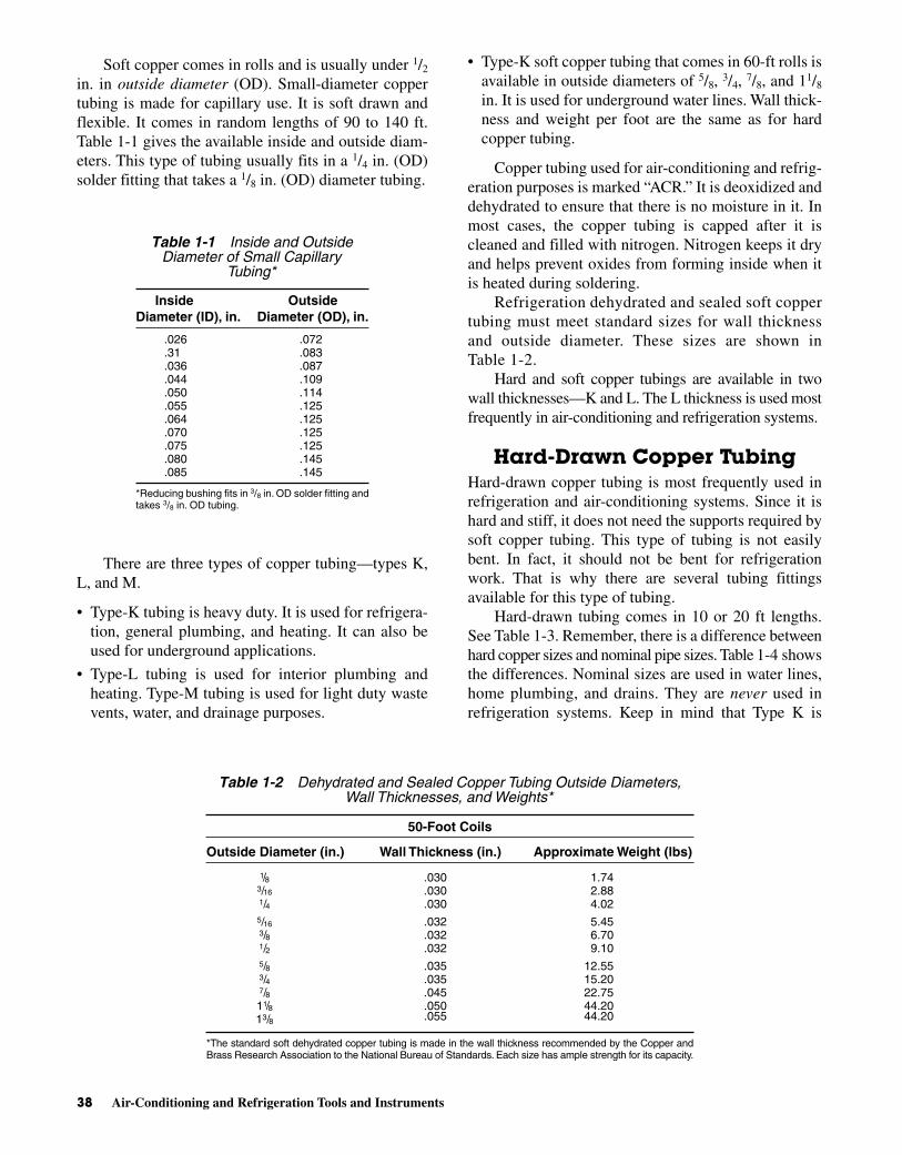
Soft copper comes in rolls and is usually under 1/2
in. in outside diameter (OD). Small-diameter coppertubing is made for capillary use. It is soft drawn andflexible. It comes in random lengths of 90 to 140 ft.Table 1-1 gives the available inside and outside diam-eters. This type of tubing usually fits in a 1/4 in. (OD)solder fitting that takes a 1/8 in. (OD) diameter tubing.
There are three types of copper tubing—types K,L, and M.
• Type-K tubing is heavy duty. It is used for refrigera-tion, general plumbing, and heating. It can also beused for underground applications.
• Type-L tubing is used for interior plumbing andheating. Type-M tubing is used for light duty wastevents, water, and drainage purposes.
• Type-K soft copper tubing that comes in 60-ft rolls isavailable in outside diameters of 5/8, 3/4, 7/8, and 11/8
in. It is used for underground water lines. Wall thick-ness and weight per foot are the same as for hardcopper tubing.
Copper tubing used for air-conditioning and refrig-eration purposes is marked “ACR.” It is deoxidized anddehydrated to ensure that there is no moisture in it. Inmost cases, the copper tubing is capped after it iscleaned and filled with nitrogen. Nitrogen keeps it dryand helps prevent oxides from forming inside when itis heated during soldering.
Refrigeration dehydrated and sealed soft coppertubing must meet standard sizes for wall thicknessand outside diameter. These sizes are shown inTable 1-2.
Hard and soft copper tubings are available in twowall thicknesses—K and L. The L thickness is used mostfrequently in air-conditioning and refrigeration systems.
Hard-Drawn Copper TubingHard-drawn copper tubing is most frequently used inrefrigeration and air-conditioning systems. Since it ishard and stiff, it does not need the supports required bysoft copper tubing. This type of tubing is not easilybent. In fact, it should not be bent for refrigerationwork. That is why there are several tubing fittingsavailable for this type of tubing.
Hard-drawn tubing comes in 10 or 20 ft lengths.See Table 1-3. Remember, there is a difference betweenhard copper sizes and nominal pipe sizes. Table 1-4 showsthe differences. Nominal sizes are used in water lines,home plumbing, and drains. They are never used inrefrigeration systems. Keep in mind that Type K is
38 Air-Conditioning and Refrigeration Tools and Instruments
Table 1-1 Inside and OutsideDiameter of Small Capillary
Tubing*
Inside Outside Diameter (ID), in. Diameter (OD), in.
.026 .072
.31 .083
.036 .087
.044 .109
.050 .114
.055 .125
.064 .125
.070 .125
.075 .125
.080 .145
.085 .145
*Reducing bushing fits in 3/8 in. OD solder fitting andtakes 3/8 in. OD tubing.
Table 1-2 Dehydrated and Sealed Copper Tubing Outside Diameters,Wall Thicknesses, and Weights*
50-Foot Coils
Outside Diameter (in.) Wall Thickness (in.) Approximate Weight (lbs)
1/8 .030 1.743/16 .030 2.881/4 .030 4.025/16 .032 5.453/8 .032 6.701/2 .032 9.105/8 .035 12.553/4 .035 15.207/8 .045 22.7511/8 .050 44.2013/8 .055 44.20
*The standard soft dehydrated copper tubing is made in the wall thickness recommended by the Copper andBrass Research Association to the National Bureau of Standards. Each size has ample strength for its capacity.
Miller_CH01.qxd 3/1/06 10:20 AM Page 38

To provide further dryness and cleanliness, nitrogen,an inert gas, is used to fill the tube. It materially reducesthe oxide formation during brazing. The remainingnitrogen limits excess oxides during succeeding brazingoperations. Where tubing will be exposed inside foodcompartments, tinned copper is recommended.
To uncoil the tube without kinks, hold one free endagainst the floor or on a bench. Uncoil along the flooror bench to the desired length. The tube may be cut tolength with a hacksaw or a tube cutler. In either case,deburr the end before flaring. Bending is accom-plished by use of an internal or external bendingspring. Lever-type bending tools may also be used.These tools will be shown and explained later.
The hacksaw should have a 32-tooth blade. Theblade should have a wave set. No filings or chips canbe allowed to enter the tubing. Hold the tubing so thatwhen it is cut the scraps will fall out of the usable end.
Figure 1-61 shows some of the tubing cuttersavailable. The tubing cutter is moved over the spot tobe cut. The cutting wheel is adjusted so it touches the
heavy-wall tubing, Type L is medium-wall tubing, andType M is thin-wall tubing. The thickness determinesthe pressure the tubing will safely handle.
Cutting Copper TubingCopper tubing can be cut with a copper tube cutter ora hacksaw. ACR tubing is cleaned, degreased, anddried before the end is sealed at the factory. The seal-ing plugs are reusable.
Tubing 39
Table 1-3 Outside Diameter, Wall Thickness, and Weightper Foot of Hard Copper Refrigeration Tubing
Outside Diameter (in.) Wall Thickness Weight Per Foot
Type-K Tubing3/8 0.035 0.1451/2 0.049 0.2695/8 0.049 0.3443/4 0.049 0.4187/8 0.065 0.64111/8 0.065 0.839
13/8 0.065 1.04015/8 0.072 1.36021/8 0.083 2.060
25/8 0.095 2.93031/8 0.109 4.00041/8 0.134 6.510
Type-L Tubing3/8 0.030 0.1261/2 0.035 0.1985/8 0.040 0.2853/4 0.042 0.3627/8 0.045 0.44511/8 0.050 0.655
13/8 0.055 0.88415/8 0.060 1.11421/8 0.070 1.75025/8 0.080 2.480
Type-M Tubing1/2 0.025 0.1455/8 0.028 0.2047/8 0.032 0.328
11/8 0.035 0.46513/8 0.042 0.68215/8 0.049 0.940
Table 1-4 Comparison of OutsideDiameter and Nominal Pipe Size
Outside Nominal PipeDiameter (in.) Size (in.)
3/8 1/41/2 3/85/8 1/23/4 —7/8 3/411/8 1
Miller_CH01.qxd 3/1/06 10:20 AM Page 39

copper. A slight pressure is applied to the tighteningknob on the cutter to penetrate the copper slightly.Then the knob is rotated around the tubing. Oncearound, it is tightened again to make a deeper cut.Rotate again to make a deeper cut. Do this by degreesso that the tubing is not crushed during the cuttingoperation.
After the tubing is cut through, it will have acrushed end. The crushed end is prepared for flaringby filing and reaming. See Fig. 1-62. A file and the
deburring attachment on the cutting tool can also beused. After the tubing is cut to length, it probably willrequire flaring or soldering.
Flaring Copper TubingA flaring tool is used to spread the end of the cut cop-per tubing outward. Two types of tools are designedfor this operation. See Fig. 1-63. The flaring process isshown in Fig. 1-64. Note that the flaring is done byholding the end of the tubing rigid at a point slightlybelow the protruding part of the tube. This protrudingpart allows for the stretching of the copper.
A flare is important for a strong, solid, leak-proofjoint. The flares shown in Fig. 1-64 are single flares.These are used in most refrigeration systems. Theother type of flare is the double flare. Here the metal isdoubled over to make a stronger joint. They are used incommercial refrigeration and automobile air condi-tioners. Figure 1-65 shows how the double flare ismade. The tool used is called a block-and-punch.
40 Air-Conditioning and Refrigeration Tools and Instruments
Fig. 1-61 Three types of tubing cutters. (Mueller Brass)
Fig. 1-62 The three steps in removing a burr after the tubinghas been cut with a tubing cutter. (A) The end of the cut tubing.(B) Squaring with a file produces a flat end. (C) The tube has beenfiled and reamed. It can now be flared.
Fig. 1-63 Two types of flaring tools for soft copper tubing.
Miller_CH01.qxd 3/1/06 10:20 AM Page 40

uses the flare connection on all three ends. The half-union elbow uses the flare at one end and a male pipethread (MPT) on the other end. A female pipe thread isdesignated by the abbreviation FPT.
Double flaring is recommended for copper tubing5/16 in. and over. Double flares are not easily formed onsmaller sizes of tubing.
Constricting TubingA tubing cutter adapted with a roller wheel is used toconstrict a tubing joint. Two tubes are placed so thatone is inserted inside the other. They should be within0.003 in. when inserted. This space is then constrictedby a special wheel on the tube cutter. See Fig. 1-68.The one shown is a combination tube cutter and con-strictor. The wheel tightens the outside tube around theinside tube. The space between the two is then filledwith solder. Of course, proper cleanliness for the sol-der joint must be observed before attempting to fill thespace with solder.
Both pieces of tubing must be hot enough to meltthe solder. Flux must be used to prevent oxidation dur-ing the heating cycle. Place flux only on the tube to beinserted. No flux should be allowed to penetrate the in-side of the tubing. It can clog filters and restrict refrig-erant flow.
Swaging Copper TubingSwaging joins two pieces of copper without a cou-pling. This makes only one joint, instead of the twothat would be formed if a coupling were used. With
Adapters can be used with a single-flare tool to pro-duce a double flare. See Fig. 1-66.
Figure 1-67 shows joints that use the flare. Theflared tubing fits over the beveled ends. The flare tee
Tubing 41
Fig. 1-64 Flaring tools. (A) This type of tool calls for the tubingto be inserted into the proper size hole with a small amount of thetube sticking above the flaring block. (B) This type of tool calls forthe tubing to stick well above the flaring block. This type is able tomaintain the original wall thickness at the base of the flare. Thefaceted flaring cone smoothes out any surface imperfections.
Fig. 1-65 Double flares formed by the punch-and-block method. (1) Tubing isclamped into the block opening of the proper size. The female punch, Punch A, is insertedinto the tubing. (2) Punch A is tapped to bend the tubing inward. (3) The male punch,Punch B, is tapped to bend the tubing inward. (4) The male punch is tapped to create thefinal double flare.
Miller_CH01.qxd 3/1/06 10:20 AM Page 41

fewer joints, there are fewer chances of leaks. Punch-type swaging tools and screw-type swaging tools areused in refrigeration work. The screw-type swagingtool works the same as the flaring tool.
Tubing is swaged so that one piece of tubing is en-larged to the outside diameter of the other tube. Thetwo pieces of soft copper are arranged so that the in-serted end of the tubing is inside the enlarged end bythe same amount as the diameter of the tubing used.See Fig. 1-69. Once the areas have been properly pre-pared for soldering, the connection is soldered. Today,most mechanics use fittings, rather than take the timeto prepare the swaged end.
Forming Refrigerant TubingThere are two types of bending tools made of springs.One fits inside the tubing. The other fits outside andover the tubing being bent. See Fig. 1-70. Tubing mustbe bent so that it does not collapse and flatten. To pre-vent this, it is necessary to place some device over thetubing to make sure that the bending pressure is ap-plied evenly. A tube bending spring may be fitted ei-ther inside or outside the copper tube while it is beingbent. See Fig. 1-71. Keep in mind that the minimumsafe distance for bending small tubing is five times itsdiameter. On larger tubing, the minimum safe distanceis ten times the diameter. This prevents the tubing fromflattening or buckling.
Make sure the bending is done slowly and care-fully. Make a large radius bend first, then go on to thesmaller bends. Do not try to make the whole bend atone time. A number of small bends will equalize theapplied pressure and prevent tubing collapse. Whenusing the internal bending spring, make sure part of it
42 Air-Conditioning and Refrigeration Tools and Instruments
Fig. 1-66 Making a double flare with an adapter for the single-flare tool. (1) Insertthe tubing into the proper size hole in the flaring bar. (2) Place the adapter over thetubing. (3) Place the adapter inside the tubing. Apply pressure with the flaring cone topush the tubing into a doubled-over configuration. (4) Remove the adapter and use theflaring cone to form a double-thickness flare.
Fig. 1-67 A half-union elbow (A) and a flare tee (B). Note the45° angle on the end of the half-union elbow fitted for a flare. Also,note the 45° angles on both ends of the flare tee. Note that theflared end does not have threads to the end of the fitting.
Fig. 1-68 Tubing cutter adapter with a roller wheel to work asa tubing constrictor.
Miller_CH01.qxd 3/1/06 10:20 AM Page 42

is outside the tubing. This gives you a handle on itwhen it is time to remove it after the bending. You mayhave to twist the spring to release it after the bend. Bybending it so the spring compresses, it will becomesmaller in diameter, and pull out easily. The externalspring is usually used in bending tubing along the mid-point. It is best to use the internal spring when a bendcomes near the end of the tubing or close to a flaredend.
The lever-type tube bender is also used for bendingcopper tubing. See Fig. 1-72. This one-piece open-sidebender makes a neat, accurate bend since it is cali-brated in degrees. It can be used to make bends up to180°. A 180° bend is U-shaped. This tool is to be usedwhen working with hard-drawn copper or steel tubing.It can also be used to bend soft copper tubing. Thesprings are used only for soft copper, since the hard-drawn copper would be difficult to bend by hand.Hard-drawn copper tubing can be bent, if necessary,using tools that electricians use to bend conduit.
Fitting Copper Tubingby Compression
Making leak-proof and vibration-proof connectionscan be difficult. A capillary tube connection can beused. See Fig. 1-73. This compression fitting is usedwith a capillary tube. The tube extends through the nutand into the connector fitting. The nose section isforced tightly against the connector fitting as the nut istightened. The tip of the nose is squeezed against thetubing.
If you service this type of fitting, you must cutback the tubing at the end and replace the soft nose nut.If the nut is reused, it will probably cause a leaky con-nection.
SOLDERINGMuch refrigeration work requires soldering. Brassparts, copper tubing, and fittings are soldered. The
Soldering 43
Fig. 1-69 Swaging tool and swaging techniques. The swagingpunches screw into the yoke and are changed for each size of tub-ing. Swages are available in 1/2, 5/8, and 7/8 in. OD, or 3/8, 1/2, and3/4 in. nominal copper and aluminum tubing sizes.
Fig. 1-70 Bending tools for soft copper tubing.
Fig. 1-71 Using a spring-type tool to bend tubing.
Miller_CH01.qxd 3/1/06 10:20 AM Page 43

cooling unit is also soldered. Thus, the air-conditioningand refrigeration mechanic should be able to solderproperly.
Two types of solders are used in refrigeration andair-conditioning work. Soft solder and silver solder aremost commonly used for making good joints. Brazingis actually silver soldering. Brazing requires carefulpreparation of the products prior to heating for brazingor soldering. This preparation must include steps toprevent contaminants such as dirt, chips, flux residue,and oxides from entering and remaining in an installa-tion. A general-purpose solder for cold water lines andhot water lines with temperatures below 250°F(121.1°C) is 50-50. The solder is made of 50 percenttin and 50 percent lead. The 50-50 solder flows at414°F (212.2°C).
Another low-temperature solder is 95-5. It flows at465°F (240.5°C). It has a higher resistance to corro-sion. It will result in a joint shear strength approxi-mately two and a half times that of a 50-50 joint at250°F (121.1°C).
A higher temperature solder is No. 122. It is 45percent silver brazing alloy. This solder flows at1145°F (618.2°C). It provides a joining material that issuitable for a joint strength greater than the other twosolders. It is recommended for use on ACR coppertubing.
Number 50 solder is 50-50 lead and tin. Number95 solder is 95 percent tin and 5 percent antimony.Silver solder is really brazing rod, instead of solder.The higher temperature requires a torch to melt it.
Soft SolderingSoldering calls for a very clean surface. Sand-cloth isused to clean the copper surfaces. Flux must be addedto prevent oxidation of the copper during the heatingprocess. A no-corrode solder is necessary. See Fig. 1-6.Acid-core solder must not be used. The acid in the sol-der will corrode the copper and cause leaks.
Soldering is nothing more than applying a moltenmetal to join two pieces of tubing or a tubing end anda fitting. It is important that both pieces of metal beingjoined are at the flow point of the solder being used.Never use the torch to melt the solder. The torch isused to heat the tubing or fitting until it is hot enoughto melt the solder.
The steps in making a good solder joint are shownin Fig. 1-74. Cleanliness is essential. Flux can damageany system. It is very important to keep flux out of thelines being soldered. The use of excessive amounts ofsolder paste affects the operation of a refrigeration sys-tem. This is especially true of R-22 systems. Solderpaste will dissolve in the refrigerant at the high liquidline temperature. It is then carried through a drier orstrainer and separated out at the colder expansionvalve temperature. Generally, R-22 systems will bemore seriously affected than those carrying R-12. Thisis because the solid materials separate out at a higher
44 Air-Conditioning and Refrigeration Tools and Instruments
Fig. 1-72 A tube bender.
Fig. 1-73 A capillary tube connection.
Miller_CH01.qxd 3/1/06 10:20 AM Page 44
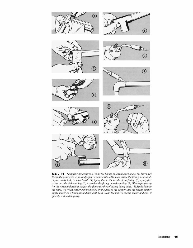
Soldering 45
Fig. 1-74 Soldering procedures. (1) Cut the tubing to length and remove the burrs. (2)Clean the joint area with sandpaper or sand-cloth. (3) Clean inside the fitting. Use sand-paper, sand-cloth, or wire brush. (4) Apply flux to the inside of the fitting. (5) Apply fluxto the outside of the tubing. (6) Assemble the fitting onto the tubing. (7) Obtain proper tipfor the torch and light it. Adjust the flame for the soldering being done. (8) Apply heat tothe joint. (9) When solder can be melted by the heat of the copper (not the torch), simplyapply solder so it flows around the joint. (10) Clean the joint of excess solder and cool itquickly with a damp rag.
Miller_CH01.qxd 3/1/06 10:21 AM Page 45

temperature. Sound practice would indicate the use ofonly enough solder paste to secure a good joint. Thepaste should be applied according to directions speci-fied by the manufacturer.
Silver Soldering or BrazingSilver solder melts at about 1120°F (604.4°C) andflows at 1145°F (618°C). An acetylene torch is neededfor the high heat. It is used primarily on hard-drawncopper tubing.
CAUTION: Before using silver solder,make sure it does not contain cadmium.Cadmium fumes are very poisonous.Make sure you work in a very well-ventilated room. The fumes should notcontact your skin or eyes. Do not breathethe fumes from the cadmium type ofsilver solder. Most manufacturers will listthe contents on the container.
Silver soldering also calls for a clean joint area.Use the same procedures as shown previously for sol-dering. See Fig. 1-74. Figure 1-75 shows good andpoor design characteristics. No flux should enter thesystem being soldered. Make your plans carefully toprevent any flux entering the tubing being soldered.
Nitrogen or carbon dioxide can be used to fill therefrigeration system during brazing. This will preventany explosion or the creation of phosgene when thejoint has been cleaned with carbon tetrachloride.
In silver soldering, you need a tip that is severalsizes larger than the one used for soft soldering. Thepieces should be heated sufficiently to have the silversolder adhere to them. Never hold the torch in oneplace. Keep it moving. Use a slight feather on the innercone of the flame to make sure you have the properheat. A large soft flame may be used to make sure thetip does not burn through the fitting or the tubing beingsoldered.
It is necessary to disassemble sweat-type valveswhen soldering to the connecting lines. In solderingsweat-type valves where they connect to a line, makesure the torch flame is directed away from the valve.Avoid excessive heat on the valve diaphragm. As anextra precaution, a damp cloth may be wrapped aroundthe diaphragm during the soldering operation. Thesame is true for soldering thermostatic expansionvalves to the distributor.
Either soft or hard solder or silver brazing is ac-ceptable in soldering thermostatic expansion valves.Keep the flame at the fittings and away from the valvebody and distributor tube joints. Do not overheat. Al-ways solder the outside diameter (OD) of the distribu-tor, never the inside diameter (ID).
46 Air-Conditioning and Refrigeration Tools and Instruments
Fig. 1-75 Designs that are useful in silver soldering copper tubing. Here, the clear-ances between the copper tubing are exaggerated for the sake of illustration. They shouldbe much less than shown here. (Handy and Harmon)
Miller_CH01.qxd 3/1/06 10:21 AM Page 46

only with extreme caution. A measureof its harmful nature is indicated by thefact that it bears a poison label. Itshould never be placed in a containerthat is not labeled “poison.” It is for in-dustrial use only.
While occasional deaths result from swallowingcarbon tetrachloride, the vast majority of deaths arecaused by breathing its vapors. When exposure is verygreat, the symptoms will be headache, dizziness, nausea,vomiting, and abdominal cramping. The person maylose consciousness. While the person seems to recoverfrom breathing too much of the vapor, a day or twolater he or she again becomes ill. Now there is evidenceof severe injury to the liver and kidneys. In many cases,this delayed injury may develop after repeated smallexposures or after a single exposure not sufficient tocause illness at the time of exposure. The delayed ill-ness is much more common and more severe amongthose who drink alcoholic beverages. In some episodeswhere several persons were equally exposed to carbontetrachloride, the only one who became ill or the onewho became most seriously ill was the person whostopped for a drink or two on the way home. Whenoverexposure to carbon tetrachloride results in liverand kidney damage, the patient begins a fight for lifewithout the benefit of an antidote. The only sure pro-tection against such serious illness is not to breathe thevapors or allow contact with the skin.
Human response to carbon tetrachloride is not pre-dictable. A person may occasionally use carbon tetra-chloride in the same job in the same way withoutapparent harm. Then, one day severe illness may result.This unpredictability of response is one factor thatmakes the use of “carbon tet” so dangerous.
Other solvents will do a good job of cleaning anddegreasing. It is much safer to select one of those sol-vents for regular use rather than to expose yourself tothe potential dangers of carbon tetrachloride.
REVIEW QUESTIONS1. What does NEC stand for?
2. What type of solder core is preferred for electricalwork?
3. What type of tips must masonry drill bits have?
4. What is a thermocouple?
5. What is a thermistor?
6. What is superheat?
7. What symbol identifies infinite resistance on anohmmeter?
TESTING FOR LEAKSNever use oxygen to test a joint for leaks. Any oil incontact with oxygen under pressure will form an explo-sive mixture.
Do not use emery cloth to clean a copper joint.Emery cloth contains oil. This may hinder the makingof a good soldering joint. Emery cloth is made of sili-con carbide, which is a very hard substance. Any grainsof this abrasive in the refrigeration mechanism or linescan damage a compressor. Use a brush to help clean thearea after sanding.
CLEANING AND DEGREASINGSOLVENTS
Solvents, including carbon tetrachloride (CCl4), arefrequently used in the refrigeration industry for clean-ing and degreasing equipment. No solvent is absolutelysafe. There are several which may be used with relativesafety. Carbon tetrachloride is not one of them. Use ofone of the safer solvents will reduce the likelihood ofserious illness developing in the course of daily use.Some of these solvents are stabilized methyl chloro-form, methylene chloride, trichlorethylene, and per-chloroethylene. Some petroleum solvents are available.These are flammable in varying degrees.
Most solvents may be used safely if certain rulesare followed.
• Use no more solvent than the job requires. This helpskeep solvent vapor concentrations low in the workarea.
• Use the solvent in a well-ventilated area and avoidbreathing the vapors as much as possible. If the sol-vents are used in shop degreasing, it is wise to have aventilated degreasing unit to keep the level of solventvapors as low as possible.
• Keep the solvents off the skin as much as possible.All solvents are capable of removing the oils andwaxes that keep the skin soft and moist. When theseoils and waxes are removed, the skin becomes irri-tated, dry, and cracked. A skin rash may developmore easily.
CAUTION: While commonly used sol-vent, carbon tetrachloride has manyvirtues as a solvent, it has causedmuch illness among those who use it.Each year several deaths result from itsuse. Usually, these occur in the smallshop or the home. Most large industrieshave discontinued its use. It is used
Review Questions 47
Miller_CH01.qxd 3/1/06 10:21 AM Page 47

8. What is a draft gage?
9. What is the difference between a sling psychrometerand a stationary psychrometer?
10. Where are humidistats used?
11. What is a British thermal unit (Btu)?
12. What is a capillary tube?
13. Why is vapor charging slower than liquid charging?
14. What is the purpose of a vacuum pump?
15. What is a micron?
16. What type of tubing is needed with R-717 orammonia refrigerant?
17. Name the three types of copper tubing and de-scribe each.
18. What does ACR on a piece of copper tubing signify?
19. How do you shape or form copper tubing withoutcollapsing it?
20. What is swaging?
21. At what temperature does silver solder melt?
48 Air-Conditioning and Refrigeration Tools and Instruments
Miller_CH01.qxd 3/1/06 10:21 AM Page 48