air-cooled condensing units with compact screw … tech bulletins folder/bn-scu-tb.pdfthe screw...
TRANSCRIPT
BN-SCUTB | March 2015
Air-Cooled Condensing Units with Compact Screw CompressorsTechnical BulletinModels SSV | DSV
2
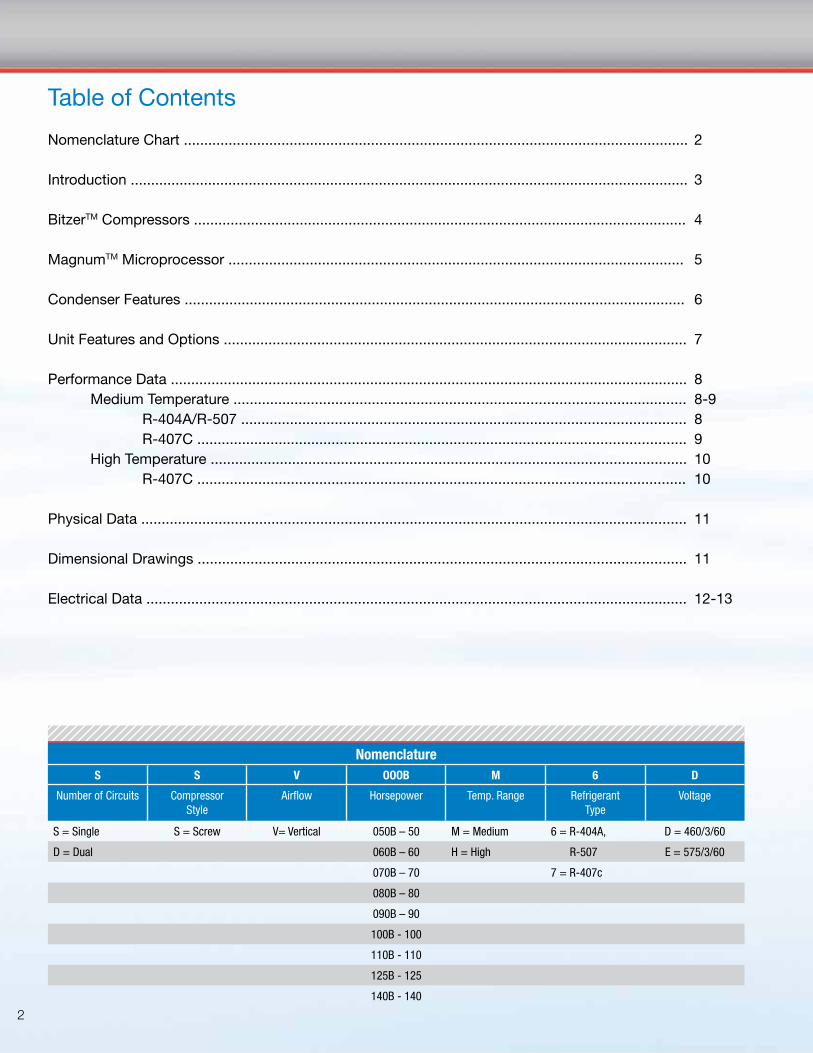
Table of Contents
Nomenclature Chart ............................................................................................................................ 2
Introduction ......................................................................................................................................... 3
BitzerTM Compressors ......................................................................................................................... 4
MagnumTM Microprocessor ................................................................................................................ 5
Condenser Features ........................................................................................................................... 6 Unit Features and Options .................................................................................................................. 7
Performance Data ............................................................................................................................... 8 Medium Temperature ............................................................................................................... 8-9 R-404A/R-507 ............................................................................................................. 8 R-407C ........................................................................................................................ 9 High Temperature ..................................................................................................................... 10 R-407C ........................................................................................................................ 10
Physical Data ...................................................................................................................................... 11
Dimensional Drawings ........................................................................................................................ 11
Electrical Data ..................................................................................................................................... 12-13
NomenclatureS S V OOOB M 6 D
Number of Circuits CompressorStyle
Airflow Horsepower Temp. Range RefrigerantType
Voltage
S = Single S = Screw V= Vertical 050B – 50 M = Medium 6 = R-404A, D = 460/3/60
D = Dual 060B – 60 H = High R-507 E = 575/3/60
070B – 70 7 = R-407c
080B – 80
090B – 90
100B - 100
110B - 110
125B - 125
140B - 140

3
The screw compressor condensing unit is an important addition to the Heatcraft air-cooled condensing unit product
family, featuring innovative compact screw compressors and advanced microprocessor controls. The unit is designed
to provide increased system reliability, reduced installation and operation costs, as well as, improved product integrity
in commercial and industrial refrigeration applications.
Increased ReliabilityThe Heatcraft screw compressor condensing unit is a reliable and rugged system, designed for the commercial and industrial
refrigeration markets. Compact screw compressors have fewer moving parts than reciprocating compressors, resulting in improved
durability. Additionally, a semi-hermetic motor design eliminates shaft seal and coupling concerns, while an integral oil system
provides improved lubrication performance. The screw compressors utilize slide valve unloading which increases motor life through
unloaded compressor starting. The new screw condensing units are factory equipped with an advanced microprocessor control
system. This control system constantly monitors and adapts by modifying multiple parameters to guarantee safe and reliable
system performance. Finally, all screw compressor condensing units come standard with a floating tube condenser coil design,
minimizing the potential for refrigerant leaks.
Reduced Costs of OwnershipScrew compressor condensing units allow owners and
operators to reduce both their installation and operating
costs. Screw compressor condensing units yield more
capacity per compressor than traditional reciprocating
compressor condensing units. The result is a reduced
number of units on large projects and subsequent
savings of time and cost during installation and
commissioning. Built-in features such as soft starting,
slide valve unloading, and digital controls make Heatcraft
screw compressor condensing units the optimum choice
for maximum performance with minimal operating costs.
Improved Product Integrity
With advanced digital controls and variable capacity capability, the screw compressor condensing units have the capability to
maintain more precise temperature control and stable product environment. Minimizing temperature fluctuations results in maximum
product integrity; all while maintaining overall system performance. Screw compressor condensing units are the right choice and the
perfect match for large, mission critical cooling applications.
THE RIGHT CHOICE FOR LARGE COOLING APPLICATIONS
4
COMPACT SCREW COMPRESSORS : FEATURES AND BENEFITS
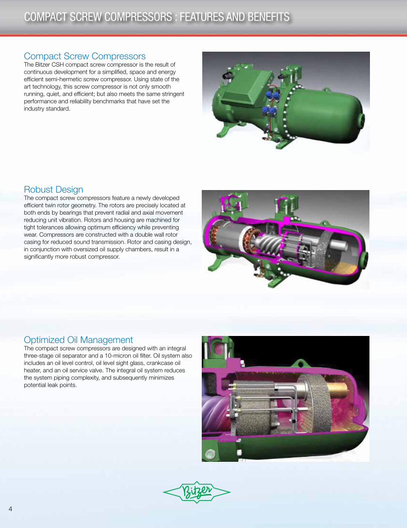
Compact Screw CompressorsThe Bitzer CSH compact screw compressor is the result of continuous development for a simplified, space and energy efficient semi-hermetic screw compressor. Using state of the art technology, this screw compressor is not only smooth running, quiet, and efficient; but also meets the same stringent performance and reliability benchmarks that have set the industry standard.
Robust DesignThe compact screw compressors feature a newly developed efficient twin rotor geometry. The rotors are precisely located at both ends by bearings that prevent radial and axial movement reducing unit vibration. Rotors and housing are machined for tight tolerances allowing optimum efficiency while preventing wear. Compressors are constructed with a double wall rotor casing for reduced sound transmission. Rotor and casing design, in conjunction with oversized oil supply chambers, result in a significantly more robust compressor.
Optimized Oil ManagementThe compact screw compressors are designed with an integral three-stage oil separator and a 10-micron oil filter. Oil system also includes an oil level control, oil level sight glass, crankcase oil heater, and an oil service valve. The integral oil system reduces the system piping complexity, and subsequently minimizes potential leak points.
5
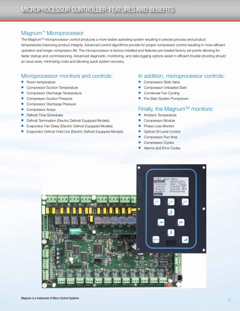
Magnum™ MicroprocessorThe MagnumTM microprocessor control produces a more stable operating system resulting in precise process and product
temperatures improving product integrity. Advanced control algorithms provide for proper compressor control resulting in more efficient
operation and longer compressor life. The microprocessor is factory installed and features pre-loaded factory set points allowing for
faster startup and commissioning. Advanced diagnostic, monitoring, and data logging options assist in efficient trouble shooting should
an issue arise, minimizing costs and allowing quick system recovery.
MICROPROCESSOR CONTROLLER: FEATURES AND BENEFITS
Magnum is a trademark of Micro Control Systems
Microprocessor monitors and controls: n Room temperaturen Compressor Suction Temperaturen Compressor Discharge Temperaturen Compressor Suction Pressuren Compressor Discharge Pressuren Compressor Ampsn Defrost Time Schedulesn Defrost Termination (Electric Defrost Equipped Models)n Evaporator Fan Delay (Electric Defrost Equipped Models)n Evaporator Defrost Hold Out (Electric Defrost Equipped Models)
In addition, microprocessor controls:n Compressor Slide Valven Compressor Unloaded Startn Condenser Fan Cyclingn Pre-Start System Pumpdown
Finally, the MagnumTM monitors:n Ambient Temperaturen Compressor Modulen Phase Loss Monitorn Optical Oil Level Controln Compressor Run timen Compressor Cyclesn Alarms and Error Codes

6
Adjustable Flooding Head Pressure Control
The Need For Head Pressure Control Refrigeration condensing units must efficiently perform at varying ambient conditions. A properly sized unit will adequately perform at the highest summer ambient temperatures. However, in situations where the system must operate the majority of the time at less than design temperature, a means of providing adequate head pressure for refrigerant flow is desirable.
Adjustable Two Valve Flooded Head Pressure ControlThe screw compressor condensing units use a factory assembled system utilizing an adjustable two valve flooding head pressure control scheme to maintain a constant head pressure at the air-cooled condensing unit during all climatic conditions when the ambient temperature drops below 75°F (typical).
When the ambient is above 75°F, the condenser pressure is above the drain regulator setting; therefore, the valve remains in the full open position.
As the temperature drops below 75°F, the pressure at the condenser also drops below the setting of the drain regulator. The drain regulator, sensing the reduction in condensing pressure, modulates toward the closed position, thus restricting the flow of liquid from the condenser. The liquid backs up into the condenser and floods a portion of the tubes, reducing the overall capacity of the condenser. The drain regulator valve will continue to flood the condenser until the pressure setting has been reached, providing proper head pressure at all ambient temperatures.
While the condenser floods, a second line pressurizes the receiver through the bypass regulator; therefore, the refrigerant flow from the condenser to the receiver modulates with conditions. However, the bypass from the discharge line maintains a minimum receiver pressure. These valves are adjustable and the minimum receiver pressure may be reset higher or lower depending upon application situations of a particular job.
BYPASSREGULATOR
CHECKVALVE
DRAINREGULATOR
STD. LIQUIDLINE OUTLET
RECEIVER DIP TUBE
COMPRESSOR
AIR COOLEDCONDENSER
DISCHARGELINE
Floating Tube™ Coil Design
All SSV/DSV condensers use the Floating Tube™ coil design to eliminate refrigerant leaks at the tube sheets. Additional anchor tubes are added to the condenser coil. Anchor tubes are expanded into the aluminum fins and condenser tube sheets. These tubes support the weight of the coil, but are not a part of the refrigerant circuit.
The tubes in the refrigerant circuit are expanded into the fins, but “float” through oversized holes in the tube sheets. Tube sheet leaks are virtually eliminated, since the tubes which carry refrigerant never come in contact with the tube sheet.
Expanded (Locked) Auxiliary TubesThese tubes do not carry refrigerant and are in place to support the fin pack and the tubes that are carrying refrigerant. They are expanded into the end and center supports.
Free Floating Circuited Coil TubesThese tubes carry refrigerant and never contact any sheet metal (end supports and center supports).
All units include a limited Five Year Warranty against condenser leaks at tube sheets and center supports.
CONDENSER FEATURES
7
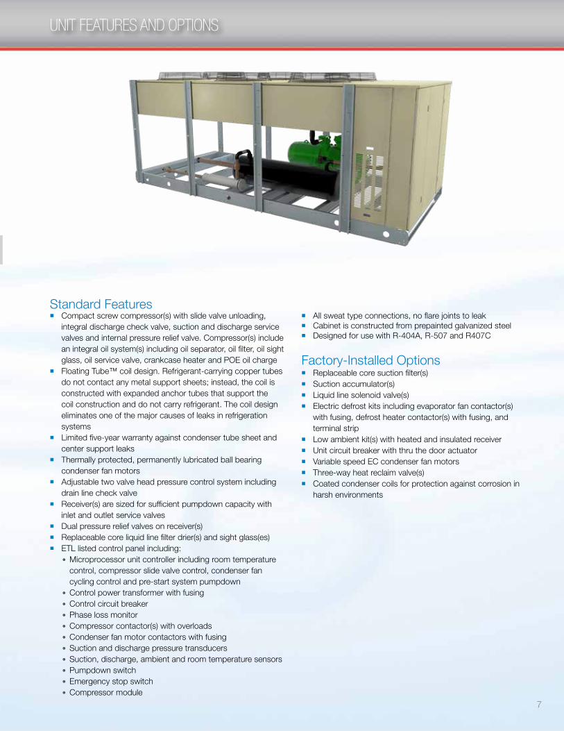
UNIT FEATURES AND OPTIONS
Standard Featuresn Compact screw compressor(s) with slide valve unloading,
integral discharge check valve, suction and discharge service valves and internal pressure relief valve. Compressor(s) include an integral oil system(s) including oil separator, oil filter, oil sight glass, oil service valve, crankcase heater and POE oil charge
n Floating Tube™ coil design. Refrigerant-carrying copper tubes do not contact any metal support sheets; instead, the coil is constructed with expanded anchor tubes that support the coil construction and do not carry refrigerant. The coil design eliminates one of the major causes of leaks in refrigeration systems
n Limited five-year warranty against condenser tube sheet and center support leaks
n Thermally protected, permanently lubricated ball bearing condenser fan motors
n Adjustable two valve head pressure control system including drain line check valve
n Receiver(s) are sized for sufficient pumpdown capacity with inlet and outlet service valves
n Dual pressure relief valves on receiver(s)n Replaceable core liquid line filter drier(s) and sight glass(es)n ETL listed control panel including:
l Microprocessor unit controller including room temperature control, compressor slide valve control, condenser fan cycling control and pre-start system pumpdown
l Control power transformer with fusingl Control circuit breakerl Phase loss monitorl Compressor contactor(s) with overloadsl Condenser fan motor contactors with fusingl Suction and discharge pressure transducersl Suction, discharge, ambient and room temperature sensorsl Pumpdown switchl Emergency stop switchl Compressor module
Factory-Installed Optionsn Replaceable core suction filter(s)n Suction accumulator(s)n Liquid line solenoid valve(s)n Electric defrost kits including evaporator fan contactor(s)
with fusing, defrost heater contactor(s) with fusing, and terminal strip
n Low ambient kit(s) with heated and insulated receiver n Unit circuit breaker with thru the door actuatorn Variable speed EC condenser fan motorsn Three-way heat reclaim valve(s)n Coated condenser coils for protection against corrosion in
harsh environments
n All sweat type connections, no flare joints to leakn Cabinet is constructed from prepainted galvanized steeln Designed for use with R-404A, R-507 and R407C
8
PERFORMANCE DATA
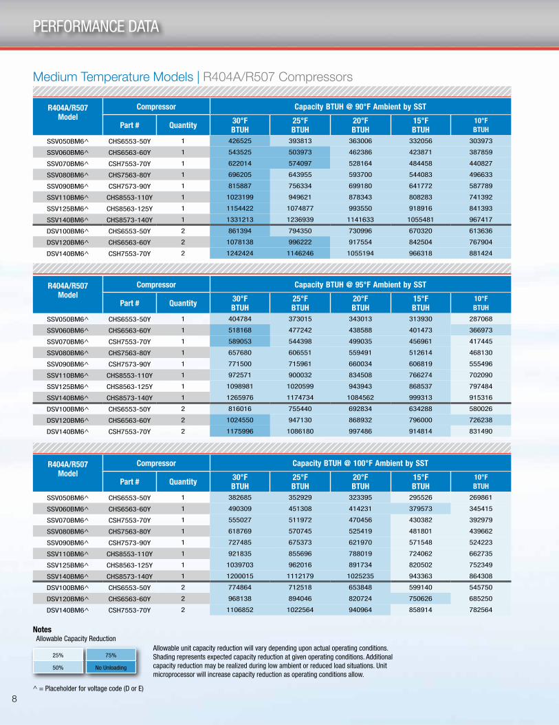
R404A/R507 Model
Compressor Capacity BTUH @ 90°F Ambient by SST
Part # Quantity 30°F BTUH
25°F BTUH
20°F BTUH
15°F BTUH
10°F BTUH
SSV050BM6^ CHS6553-50Y 1 426525 393813 363006 332056 303973
SSV060BM6^ CHS6563-60Y 1 543525 503973 462386 423871 387859
SSV070BM6^ CSH7553-70Y 1 622014 574097 528164 484458 440827
SSV080BM6^ CHS7563-80Y 1 696205 643955 593700 544083 496633
SSV090BM6^ CSH7573-90Y 1 815887 756334 699180 641772 587789
SSV110BM6^ CHS8553-110Y 1 1023199 949621 878343 808283 741392
SSV125BM6^ CHS8563-125Y 1 1154422 1074877 993550 918916 841393
SSV140BM6^ CHS8573-140Y 1 1331213 1236939 1141633 1055481 967417
DSV100BM6^ CHS6553-50Y 2 861394 794350 730996 670320 613636
DSV120BM6^ CHS6563-60Y 2 1078138 996222 917554 842504 767904
DSV140BM6^ CSH7553-70Y 2 1242424 1146246 1055194 966318 881424
Medium Temperature Models | R404A/R507 Compressors
R404A/R507 Model
Compressor Capacity BTUH @ 95°F Ambient by SST
Part # Quantity 30°F BTUH
25°F BTUH
20°F BTUH
15°F BTUH
10°F BTUH
SSV050BM6^ CHS6553-50Y 1 404784 373015 343013 313930 287068
SSV060BM6^ CHS6563-60Y 1 518168 477242 438588 401473 366973
SSV070BM6^ CSH7553-70Y 1 589053 544398 499035 456961 417445
SSV080BM6^ CHS7563-80Y 1 657680 606551 559491 512614 468130
SSV090BM6^ CSH7573-90Y 1 771500 715961 660034 606819 555496
SSV110BM6^ CHS8553-110Y 1 972571 900032 834508 766274 702090
SSV125BM6^ CHS8563-125Y 1 1098981 1020599 943943 868537 797484
SSV140BM6^ CHS8573-140Y 1 1265976 1174734 1084562 999313 915316
DSV100BM6^ CHS6553-50Y 2 816016 755440 692834 634288 580026
DSV120BM6^ CHS6563-60Y 2 1024550 947130 868932 796000 726238
DSV140BM6^ CSH7553-70Y 2 1175996 1086180 997486 914814 831490
R404A/R507 Model
Compressor Capacity BTUH @ 100°F Ambient by SST
Part # Quantity 30°F BTUH
25°F BTUH
20°F BTUH
15°F BTUH
10°F BTUH
SSV050BM6^ CHS6553-50Y 1 382685 352929 323395 295526 269861
SSV060BM6^ CHS6563-60Y 1 490309 451308 414231 379573 345415
SSV070BM6^ CSH7553-70Y 1 555027 511972 470456 430382 392979
SSV080BM6^ CHS7563-80Y 1 618769 570745 525419 481801 439662
SSV090BM6^ CSH7573-90Y 1 727485 675373 621970 571548 524223
SSV110BM6^ CHS8553-110Y 1 921835 855696 788019 724062 662735
SSV125BM6^ CHS8563-125Y 1 1039703 962016 891734 820502 752349
SSV140BM6^ CHS8573-140Y 1 1200015 1112179 1025235 943363 864308
DSV100BM6^ CHS6553-50Y 2 774864 712518 653848 599140 545750
DSV120BM6^ CHS6563-60Y 2 968138 894046 820724 750626 685250
DSV140BM6^ CSH7553-70Y 2 1106852 1022564 940964 858914 782564
Allowable unit capacity reduction will vary depending upon actual operating conditions. Shading represents expected capacity reduction at given operating conditions. Additional capacity reduction may be realized during low ambient or reduced load situations. Unit microprocessor will increase capacity reduction as operating conditions allow.
Notes Allowable Capacity Reduction
^ = Placeholder for voltage code (D or E)
25%
50%
75%
No Unloading

9
PERFORMANCE DATA
R407C ModelCompressor Capacity BTUH @ 90°F Ambient by SST
Part # Quantity 30°F BTUH
25°F BTUH
20°F BTUH"
15°F BTUH
10°F BTUH
SSV050BM7^ CHS6553-50Y 1 386365 352990 321034 290863 262280
SSV060BM7^ CHS6563-60Y 1 493154 449269 408544 370617 333312
SSV070BM7^ CSH7553-70Y 1 564712 515134 467560 423248 380699
SSV080BM7^ CHS7563-80Y 1 637661 581135 528527 478121 430776
SSV090BM7^ CSH7573-90Y 1 745656 684741 623891 566345 510328
SSV100BM7^ CSH7583-100Y 1 868350 795016 728430 662953 600354
SSV110BM7^ CHS8553-110Y 1 981154 900158 822278 749184 680657
SSV125BM7^ CHS8563Y-125 1 1154422 1074877 993550 918916 841393
SSV140BM7^ CHS8573-140Y 1 1229670 1127670 1027693 937122 847263
DSV100BM7^ CHS6553-50Y 2 979650 897252 816938 740308 668068
DSV120BM7^ CHS6563-60Y 2 979650 897252 816938 740308 668068
DSV140BM7^ CSH7553-70Y 2 1137044 1037494 942276 851880 766882
Medium Temperature Models | R407C Compressors
R407C ModelCompressor Capacity BTUH @ 95°F Ambient by SST
Part # Quantity 30°F BTUH
25°F BTUH
20°F BTUH
15°F BTUH
10°F BTUH
SSV050BM7^ CHS6553-50Y 1 369024 336625 305822 276577 249590
SSV060BM7^ CHS6563-60Y 1 470481 429369 390074 353056 317028
SSV070BM7^ CSH7553-70Y 1 539547 491486 446650 402461 361638
SSV080BM7^ CHS7563-80Y 1 605865 554757 504194 454673 410224
SSV090BM7^ CSH7573-90Y 1 712402 654200 595741 539260 486581
SSV100BM7^ CSH7583-100Y 1 829650 763518 697500 633554 575108
SSV110BM7^ CHS8553-110Y 1 941764 863955 786942 718157 649336
SSV125BM7^ CHS8563Y-125 1 1098981 1020599 943943 868537 797484
SSV140BM7^ CHS8573-140Y 1 1178594 1080735 986291 894641 811338
DSV100BM7^ CHS6553-50Y 2 939514 857670 778164 704122 634518
DSV120BM7^ CHS6563-60Y 2 939514 857670 778164 704122 634518
DSV140BM7^ CSH7553-70Y 2 1086050 987306 898546 811978 730376
R407C ModelCompressor Capacity BTUH @ 100°F Ambient by SST
Part # Quantity 30°F BTUH
25°F BTUH
20°F BTUH
15°F BTUH
10°F BTUH
SSV050BM7^ CHS6553-50Y 1 350823 319798 290657 261749 235110
SSV060BM7^ CHS6563-60Y 1 448429 409406 370264 334164 299971
SSV070BM7^ CSH7553-70Y 1 513775 467612 424665 382159 343126
SSV080BM7^ CHS7563-80Y 1 577665 525386 478024 430973 388461
SSV090BM7^ CSH7573-90Y 1 680744 622807 565912 512604 462311
SSV100BM7^ CSH7583-100Y 1 792215 727045 665512 606003 548674
SSV110BM7^ CHS8553-110Y 1 900483 822962 751417 684622 619701
SSV125BM7^ CHS8563Y-125 1 1039703 962016 891734 820502 752349
SSV140BM7^ CHS8573-140Y 1 1127175 1032330 939678 853159 772657
DSV100BM7^ CHS6553-50Y 2 895454 814250 739016 669488 602046
DSV120BM7^ CHS6563-60Y 2 895454 814250 739016 669488 602046
DSV140BM7^ CSH7553-70Y 2 1034062 939404 854686 769704 691728
Allowable unit capacity reduction will vary depending upon actual operating conditions. Shading represents expected capacity reduction at given operating conditions. Additional capacity reduction may be realized during low ambient or reduced load situations. Unit microprocessor will increase capacity reduction as operating conditions allow.
Notes Allowable Capacity Reduction
^ = Placeholder for voltage code (D or E)
25%
50%
75%
No Unloading
10
PERFORMANCE DATA
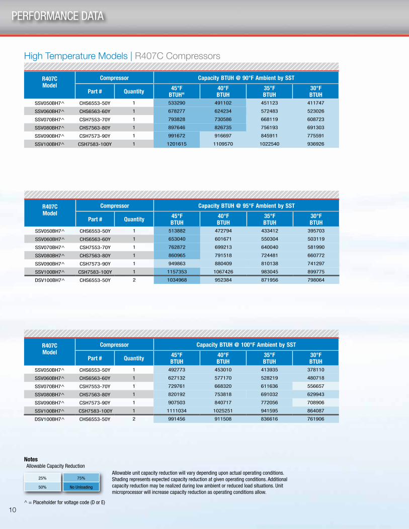
R407CModel
Compressor Capacity BTUH @ 90°F Ambient by SST
Part # Quantity 45°F BTUH"
40°F BTUH
35°F BTUH
30°F BTUH
SSV050BH7^ CHS6553-50Y 1 533290 491102 451123 411747
SSV060BH7^ CHS6563-60Y 1 678277 624234 572483 523026
SSV070BH7^ CSH7553-70Y 1 793828 730586 668119 608723
SSV080BH7^ CHS7563-80Y 1 897646 826735 756193 691303
SSV090BH7^ CSH7573-90Y 1 991672 916697 845911 775591
SSV100BH7^ CSH7583-100Y 1 1201615 1109570 1022540 936926
High Temperature Models | R407C Compressors
R407CModel
Compressor Capacity BTUH @ 95°F Ambient by SST
Part # Quantity 45°F BTUH
40°F BTUH
35°F BTUH
30°F BTUH
SSV050BH7^ CHS6553-50Y 1 513882 472794 433412 395703
SSV060BH7^ CHS6563-60Y 1 653040 601671 550304 503119
SSV070BH7^ CSH7553-70Y 1 762872 699213 640040 581990
SSV080BH7^ CHS7563-80Y 1 860965 791518 724481 660772
SSV090BH7^ CSH7573-90Y 1 949863 880409 810138 741297
SSV100BH7^ CSH7583-100Y 1 1157353 1067426 983045 899775
DSV100BH7^ CHS6553-50Y 2 1034968 952384 871956 798064
R407CModel
Compressor Capacity BTUH @ 100°F Ambient by SST
Part # Quantity 45°F BTUH
40°F BTUH
35°F BTUH
30°F BTUH
SSV050BH7^ CHS6553-50Y 1 492773 453010 413935 378110
SSV060BH7^ CHS6563-60Y 1 627132 577170 528219 480718
SSV070BH7^ CSH7553-70Y 1 729761 668320 611636 556657
SSV080BH7^ CHS7563-80Y 1 820192 753818 691032 629943
SSV090BH7^ CSH7573-90Y 1 907503 840717 772056 708906
SSV100BH7^ CSH7583-100Y 1 1111034 1025251 941595 864087
DSV100BH7^ CHS6553-50Y 2 991456 911508 836616 761906
Allowable unit capacity reduction will vary depending upon actual operating conditions. Shading represents expected capacity reduction at given operating conditions. Additional capacity reduction may be realized during low ambient or reduced load situations. Unit microprocessor will increase capacity reduction as operating conditions allow.
Notes Allowable Capacity Reduction
^ = Placeholder for voltage code (D or E)
25%
50%
75%
No Unloading
11
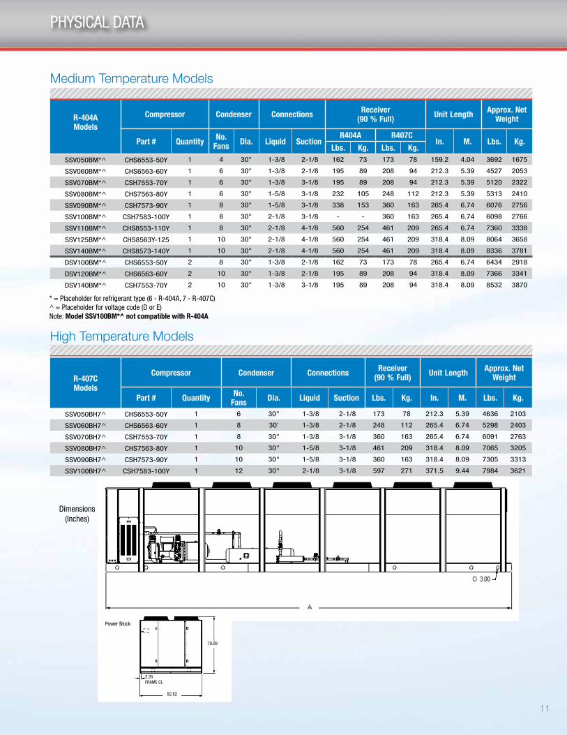
PHYSICAL DATA
R-404A Models
Compressor Condenser Connections Receiver (90 % Full) Unit Length Approx. Net
Weight
Part # Quantity No. Fans Dia. Liquid Suction
R404A R407C In. M. Lbs. Kg.
Lbs. Kg. Lbs. Kg.SSV050BM*^ CHS6553-50Y 1 4 30" 1-3/8 2-1/8 162 73 173 78 159.2 4.04 3692 1675
SSV060BM*^ CHS6563-60Y 1 6 30" 1-3/8 2-1/8 195 89 208 94 212.3 5.39 4527 2053
SSV070BM*^ CSH7553-70Y 1 6 30" 1-3/8 3-1/8 195 89 208 94 212.3 5.39 5120 2322
SSV080BM*^ CHS7563-80Y 1 6 30" 1-5/8 3-1/8 232 105 248 112 212.3 5.39 5313 2410
SSV090BM*^ CSH7573-90Y 1 8 30" 1-5/8 3-1/8 338 153 360 163 265.4 6.74 6076 2756
SSV100BM*^ CSH7583-100Y 1 8 30" 2-1/8 3-1/8 - - 360 163 265.4 6.74 6098 2766
SSV110BM*^ CHS8553-110Y 1 8 30" 2-1/8 4-1/8 560 254 461 209 265.4 6.74 7360 3338
SSV125BM*^ CHS8563Y-125 1 10 30" 2-1/8 4-1/8 560 254 461 209 318.4 8.09 8064 3658
SSV140BM*^ CHS8573-140Y 1 10 30" 2-1/8 4-1/8 560 254 461 209 318.4 8.09 8336 3781
DSV100BM*^ CHS6553-50Y 2 8 30" 1-3/8 2-1/8 162 73 173 78 265.4 6.74 6434 2918
DSV120BM*^ CHS6563-60Y 2 10 30" 1-3/8 2-1/8 195 89 208 94 318.4 8.09 7366 3341
DSV140BM*^ CSH7553-70Y 2 10 30" 1-3/8 3-1/8 195 89 208 94 318.4 8.09 8532 3870
Medium Temperature Models
R-407C Models
Compressor Condenser Connections Receiver (90 % Full) Unit Length Approx. Net
Weight
Part # Quantity No. Fans Dia. Liquid Suction Lbs. Kg. In. M. Lbs. Kg.
SSV050BH7^ CHS6553-50Y 1 6 30" 1-3/8 2-1/8 173 78 212.3 5.39 4636 2103
SSV060BH7^ CHS6563-60Y 1 8 30' 1-3/8 2-1/8 248 112 265.4 6.74 5298 2403
SSV070BH7^ CSH7553-70Y 1 8 30" 1-3/8 3-1/8 360 163 265.4 6.74 6091 2763
SSV080BH7^ CHS7563-80Y 1 10 30" 1-5/8 3-1/8 461 209 318.4 8.09 7065 3205
SSV090BH7^ CSH7573-90Y 1 10 30" 1-5/8 3-1/8 360 163 318.4 8.09 7305 3313
SSV100BH7^ CSH7583-100Y 1 12 30" 2-1/8 3-1/8 597 271 371.5 9.44 7984 3621
High Temperature Models
* = Placeholder for refrigerant type (6 - R-404A, 7 - R-407C)^ = Placeholder for voltage code (D or E)Note: Model SSV100BM*^ not compatible with R-404A
Dimensions (Inches)
Power Block
79.09
82.82
2.35FRAME CL
12
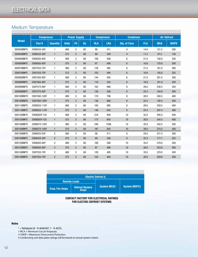
ELECTRICAL DATA
Medium Temperature
Model
Compressor Power Supply Compressor Condenser Air Defrost
Part # Quantity Volts Ph Hz RLA LRA Qty. of Fans FLA MCA MOPD
SSV050BM*D CHS6553-50Y 1 460 3 60 86 411 4 14.0 121.5 200
SSV050BM*E CHS6553-50Y 1 575 3 60 69 329 4 11.2 97.5 150
SSV060BM*D CHS6563-60Y 1 460 3 60 108 508 6 21.0 156.0 250
SSV060BM*E CHS6563-60Y 1 575 3 60 87 406 6 16.8 125.6 200
SSV070BM*D CSH7553-70Y 1 460 3 60 128 485 6 21.0 181.0 300
SSV070BM*E CSH7553-70Y 1 575 3 60 103 404 6 16.8 145.6 225
SSV080BM*D CHS7563-80Y 1 460 3 60 144 585 6 21.0 201.0 300
SSV080BM*E CHS7563-80Y 1 575 3 60 116 433 6 16.8 161.8 250
SSV090BM*D CSH7573-90Y 1 460 3 60 162 686 8 28.0 230.5 350
SSV090BM*E CSH7573-90Y 1 575 3 60 130 546 8 22.4 184.9 300
SSV100BM7D CSH7583-100Y 1 460 3 60 170 796 8 28.0 240.5 400
SSV100BM7E CSH7583-100Y 1 575 3 60 136 666 8 22.4 192.4 350
SSV110BM*D CHS8553-110Y 1 460 3 60 185 985 8 28.0 259.3 400
SSV110BM*E CHS8553-110Y 1 575 3 60 148 642 8 22.4 207.4 300
SSV125BM*D CHS8563Y-125 1 460 3 60 216 958 10 35.0 305.0 500
SSV125BM*E CHS8563Y-125 1 575 3 60 173 843 10 28.0 244.3 400
SSV140BM*D CHS8573-140Y 1 460 3 60 246 1036 10 35.0 342.5 500
SSV140BM*E CHS8573-140Y 1 575 3 60 197 835 10 28.0 274.3 450
DSV100BM*D CSH6553-50Y 2 460 3 60 86 411 8 28.0 221.5 300
DSV100BM*E CSH6553-50Y 2 575 3 60 69 329 8 22.4 177.7 225
DSV120BM*D CSH6563-60Y 2 460 3 60 108 508 10 35.0 278.0 350
DSV120BM*E CSH6563-60Y 2 575 3 60 87 406 10 28.0 223.8 300
DSV140BM*D CSH7553-70Y 2 460 3 60 128 485 10 35.0 323.0 450
DSV140BM*E CSH7553-70Y 2 575 3 60 103 404 10 28.0 259.8 350
* = Refrigerant (6 - R-404A/507; 7 - R-407C)† MCA = Minimum Circuit Ampacity†† MOP = Maximum Overcurrent Protection‡ Condensing unit data plate ratings will be based on actual system match.
Notes
CONTACT FACTORY FOR ELECTRICAL RATINGS FOR ELECTRIC DEFROST SYSTEMS
Electric Defrost ‡
Remote Loads
System MCA† System MOP††Evap. Fan Amps Defrost Heaters
Amps
2175 West Park Place Blvd. · Stone Mountain, GA 30087Phone: 800.537.7775 · Fax: 770.465.5900heatcraftrpd.com
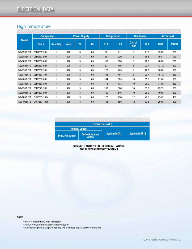
Model
Compressor Power Supply Compressor Condenser Air Defrost
Part # Quantity Volts Ph Hz RLA LRAQty. of Fans
FLA MCA MOPD
SSV050BH7D CSH6553-50Y 1 460 3 60 86 411 6 21.0 128.5 200
SSV050BH7E CSH6553-50Y 1 575 3 60 69 329 6 16.8 103.1 150
SSV060BH7D CSH6563-60Y 1 460 3 60 108 508 8 28.0 163.0 250
SSV060BH7E CSH6563-60Y 1 575 3 60 87 406 8 22.4 131.2 200
SSV070BH7D CSH7553-70Y 1 460 3 60 128 485 8 28.0 188.0 300
SSV070BH7E CSH7553-70Y 1 575 3 60 103 404 8 22.4 151.2 250
SSV080BH7D CSH7563-80Y 1 460 3 60 144 585 10 35.0 215.0 350
SSV080BH7E CSH7563-80Y 1 575 3 60 116 433 10 28.0 173.0 250
SSV090BH7D CSH7573-90Y 1 460 3 60 162 686 10 35.0 237.5 350
SSV090BH7E CSH7573-90Y 1 575 3 60 130 546 10 28.0 190.5 300
SSV100BH7D CHS7853-100Y 1 460 3 60 170 796 12 42.0 254.5 400
SSV100BH7E CHS7853-100Y 1 575 3 60 136 666 12 33.6 203.6 300
High Temperature
©2015 Heatcraft Refrigeration Products LLC
ELECTRICAL DATA
† MCA = Minimum Circuit Ampacity†† MOP = Maximum Overcurrent Protection‡ Condensing unit data plate ratings will be based on actual system match.
Notes
CONTACT FACTORY FOR ELECTRICAL RATINGS FOR ELECTRIC DEFROST SYSTEMS
Electric Defrost ‡
Remote Loads
System MCA† System MOP††Evap. Fan Amps Defrost Heaters
Amps

14
NOTES

15
NOTES

2175 West Park Place Blvd. · Stone Mountain, GA 30087Phone: 800.537.7775 · Fax: 770.465.5900heatcraftrpd.com
©2015 Heatcraft Refrigeration Products LLC