air-cooled global chiller - daikin...
TRANSCRIPT

Installation and Operation Manual IOM 686
Group: Chiller
Part Number: 062994901
Effective: March 1997
Supersedes: None
© 1997 McQuay International
Air-Cooled Global Chiller
Type AGZ 030A through 065A60 Hertz, English and MetricScroll Compressors using Refrigerant R-22
2 AGZ 030A through 065A IOM 686
Table of Contents
Introduction .........................................3
General Description....................................... 3Inspection ....................................................... 3
Installation ...........................................4
Handling ......................................................... 4Location.......................................................... 5Service Access................................................ 5Vibration Isolators ......................................... 6Water Piping................................................... 7Flow Switch ................................................... 9Water Connections......................................... 9Refrigerant Charge......................................... 9Superheat and Subcooling ............................. 9Glycol Solutions .......................................... 10Evaporator Water Flow and Pressure Drop 11
Physical Data .....................................13
Electrical Data ...................................16
Field Wiring ................................................. 16
Dimensional Data..............................28
AGZ Unit Check-out.........................29
Water piping checkout ................................. 29Refrigerant piping checkout ........................ 29Electrical Check Out.................................... 29AGZ Troubleshooting Chart........................ 30
Global UNT Controller Installationand Operation....................................31
General Description..................................... 31
Optional Sensors.......................................... 31Pre Start-up .................................................. 31Start-Up ........................................................ 31Shutdown...................................................... 32Sequence of Operation................................. 33Standard Controller Setpoints (optional ZoneTerminal required to change values)........... 33Software Description (Global UNT InterfaceKit required to read or change variables).... 34Hot Gas Bypass (Optional).......................... 34Combination Filter Drier............................. 35System Adjustment ...................................... 35Liquid Sightglass and Moisture Indicator... 35Refrigerant Charging ................................... 35Thermostatic Expansion Valve.................... 35Crankcase Heaters........................................ 36Water Cooler ................................................ 36Controller Inputs /Outputs .......................... 38Additional Global UNT Controller Features41Alarms .......................................................... 43ZONE TERMINAL (optional).................... 44Zone Terminal Glossary............................... 48Global UNT Controller TroubleshootingChart ............................................................. 50
MicroTech Controller Installationand Operation....................................51
General Description..................................... 51Optional Sensor Packages ........................... 51Installation.................................................... 51Sequence of Operation................................. 60Start-Up and Shutdown................................ 62Keypad / Display .......................................... 63Menu Descriptions....................................... 66Trouble Analysis for the AGZ MicroTechController ..................................................... 77Test Procedures............................................ 79
"McQuay" is a registered trademark of McQuay International1997 McQuay International
"Illustrations cover the general appearance of McQuay International products at the time of publication and wereserve the right to make changes in design and construction at anytime without notice"
IOM 686 AGZ 030A through 065A 3
Introduction
General DescriptionMcQuay Air-Cooled Global water chillers are complete, self-contained automatic refrigerating units.Every unit is completely assembled, factory wired, charged, and tested. Each unit consists of twin Air-Cooled condensers with integral subcooler sections, multiple tandem scroll compressors, replaceabletube dual circuit shell-and-tube evaporator, and complete refrigerant piping. Liquid line componentsinclude manual liquid line shutoff valves, sight-glass/moisture indicators, solenoid valves, and doublediaphragm hydraulic element thermal expansion valves. Other features include compressor crankcaseheaters, an evaporator heater for chilled water freeze protection, limited pumpdown during “on” or“off” periods, compressor lead-lag switch to alternate the compressor starting sequence, and sequencedstarting of compressors.
The electrical control center includes all safety and operating controls necessary for dependableautomatic operation. Condenser fan motors are fused in all three phases and started by their ownthree-pole contactors. Compressors are not fused but may be protected by optional circuit breakers.
InspectionCheck all items carefully against the bill of lading. Inspect all units for damage upon arrival. Reportshipping damage and file a claim with the carrier. Check the unit name plate before unloading, makingcertain it agrees with the power supply available. McQuay is not responsible for physical damage afterunit leaves the factory.
Note: Unit shipping and operating weights are available in the Physical Data tablesbeginning on page 13.
4 AGZ 030A through 065A IOM 686
Installation
Note: Installation is to be performed by qualified personnel who are familiar with localcodes and regulations.
WARNINGSharp edges and coil surfaces are a potential hazard. Avoid contact with them.
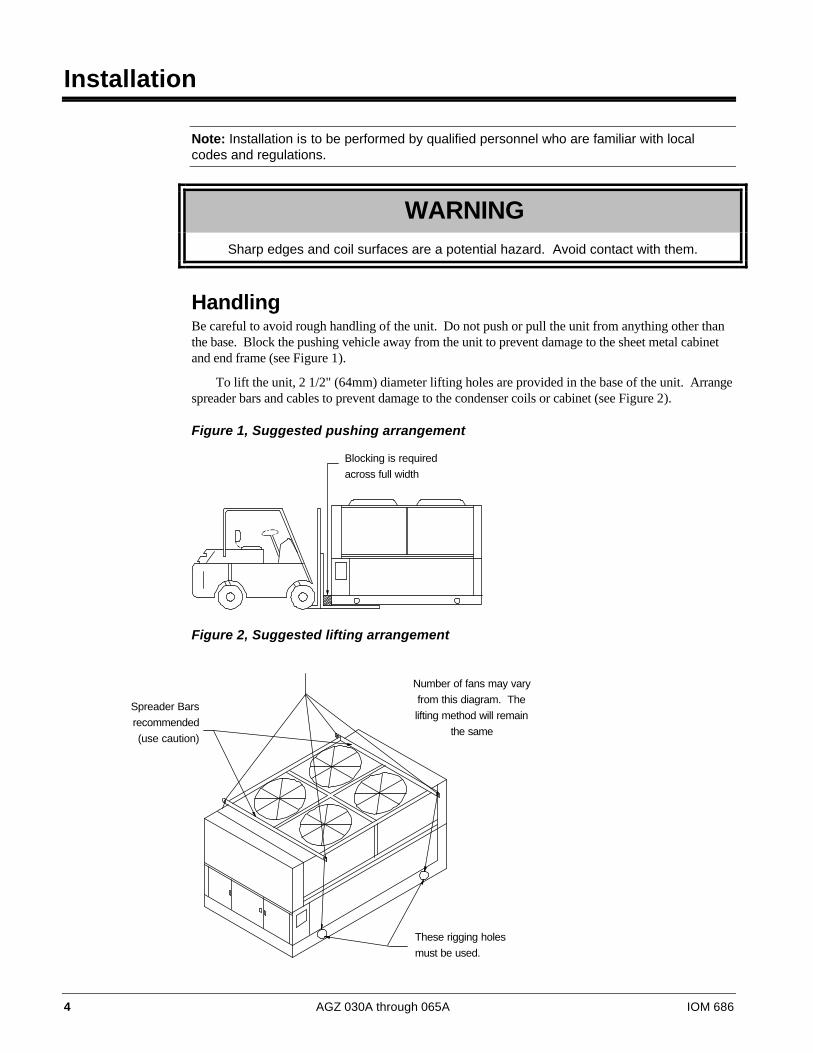
HandlingBe careful to avoid rough handling of the unit. Do not push or pull the unit from anything other thanthe base. Block the pushing vehicle away from the unit to prevent damage to the sheet metal cabinetand end frame (see Figure 1).
To lift the unit, 2 1/2" (64mm) diameter lifting holes are provided in the base of the unit. Arrangespreader bars and cables to prevent damage to the condenser coils or cabinet (see Figure 2).
Figure 1, Suggested pushing arrangement
Figure 2, Suggested lifting arrangement
These rigging holes
must be used.
Spreader Bars
recommended
(use caution)
Number of fans may vary
from this diagram. The
lifting method will remain
the same
Blocking is required
across full width
IOM 686 AGZ 030A through 065A 5
Location
Unit PlacementAGZ units are for outdoor applications and can be mounted on a roof or ground level. Set units on asolid and level foundation. For roof mounted applications, install the unit on a steel channel or I-beamframe to support the unit above the roof. For ground level applications, install the unit on asubstantial base that will not settle. A one piece concrete slab with footings extended below the frostline is recommended. Be sure the foundation is level (within 1/2” [13 mm] over its length and width).The foundation must support the operating weights listed in the Physical Data tables beginning on page13.
On ground level applications protect fins against vandalism using the optional coil guards or byerecting a screen fence. The fence must allow free flow of air to the condenser coil for proper unitoperation.
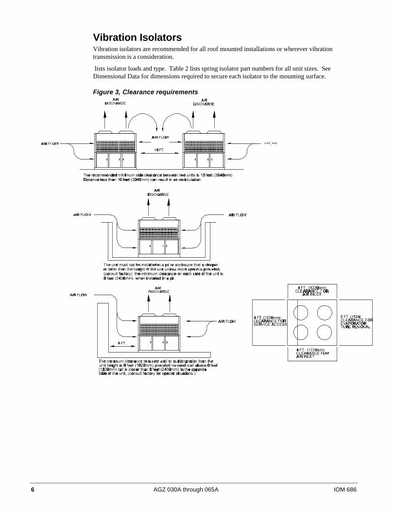
ClearancesThe flow of air to and from the condenser coil must not be limited. Restricting air flow or allowingair recirculation will result in a decrease in unit performance and efficiency. There must be noobstruction above the unit that would deflect discharge air downward where it could be recirculatedback to the inlet of the condenser coil. The condenser fans are propeller type and will not operate withductwork on the fan outlet.
Install the unit with enough side clearance for air entrance to the coil and for servicing. Provideservice access to the evaporator, compressors, electrical control panel and piping components asshown in Figure 3.
Do not allow debris to accumulate near the unit. Air movement may draw debris into thecondenser coil causing air starvation. Give special consideration to low ambient operation wheresnow can accumulate. Keep condenser coils and fan discharge free of snow or other obstructions topermit adequate airflow.
Sound IsolationThe ultra-low sound levels of the AGZ chiller is suitable for most applications. When additionalsound reduction is necessary, locate the unit away from sound sensitive areas. Avoid locations beneathwindows or between structures where normal operating sounds may be objectionable. Reducestructurally transmitted sound by isolating water lines, electrical conduit and the unit itself. Use wallsleeves and rubber isolated piping hangers to reduce transmission of water or pump noise intooccupied spaces. Use flexible electrical conduit to isolate sound through electrical conduit. Springisolators are effective in reducing the low amplitude sound generated by reciprocating compressorsand for unit isolation in sound sensitive areas.
Service AccessEach end of the unit must be accessible after installation for periodic service. Compressors, filter-driers, and manual liquid line shutoff valves are accessible. High pressure control is located in thecontrol panel when using the Global UNT controller, and on the compressor when using theMicroTech controller. Low pressure, and motor protector controls are on the compressor. Most otheroperational, safety and starting controls are located in the unit control box.
The condenser fan and motors can be removed from the top of the unit.
6 AGZ 030A through 065A IOM 686
Vibration IsolatorsVibration isolators are recommended for all roof mounted installations or wherever vibrationtransmission is a consideration.
lists isolator loads and type. Table 2 lists spring isolator part numbers for all unit sizes. SeeDimensional Data for dimensions required to secure each isolator to the mounting surface.
Figure 3, Clearance requirements

IOM 686 AGZ 030A through 065A 7
The spring flex isolators are white type CP2-32, McQuay part number 047792932. A total of four perunit is required.
Figure 4, Isolator Locations
Table 1 , Isolator Loads at each Mounting Location with Aluminum FinsUnit 1 2 3 4 Total UnitSize Lb Kg Lb Kg Lb Kg Lb Kg Lb Kg
030AS 838 380 944 428 773 351 870 395 3425 1554035AS 850 386 960 435 785 356 885 401 3480 1579040AS 864 392 974 442 797 362 900 408 3535 1603045AS 928 421 1048 475 858 389 966 438 3800 1724050AS 940 426 1062 482 868 394 980 445 3850 1746055AS 990 449 1118 507 915 415 1032 468 4055 1839060AS 1006 456 1134 514 928 421 1047 475 4115 1867065AS 1050 476 1184 537 970 440 1091 495 4295 1948030AE 852 386 960 435 786 357 887 402 3485 1581040AE 904 410 1017 461 834 378 940 426 3695 1676050AE 980 445 1105 501 905 411 1020 463 4010 1819
Table 2, Isolator Loads at each Mounting Location with Copper FinsUnit 1 2 3 4 Total UnitSize Lb Kg Lb Kg Lb Kg Lb Kg Lb Kg
030AS 946 429 1066 484 873 396 985 447 3870 1755035AS 960 435 1082 491 886 402 997 452 3925 1780040AS 973 441 1096 497 899 408 1012 459 3980 1805045AS 1038 471 1170 531 958 435 1079 489 4245 1926050AS 1050 476 1184 537 970 440 1091 495 4295 1948055AS 1154 523 1300 590 1066 484 1200 544 4720 2141060AS 1166 529 1320 599 1078 489 1216 552 4780 2168065AS 1252 568 1412 640 1156 524 1305 592 5125 2325030AE 960 435 1083 491 887 402 1000 454 3930 1783040AE 1066 484 1202 545 984 446 1108 503 4360 1978050AE 1142 518 1288 584 1055 479 1190 540 4675 2121
Water PipingLocal authorities can supply the installer with the proper building and safety codes required for safeand proper installation.
Install piping with minimum bends and changes in elevation to minimize pressure drop. Considerthe following when installing water piping:
1. Vibration eliminators to reduce vibration and noise transmission to the building.
2. Shutoff valves to isolate the unit from the piping system during unit servicing.
8 AGZ 030A through 065A IOM 686
3. Manual or automatic air vent valves at the high points of the system. Install drains at the lowestpoints in the system.
4. A means of maintaining adequate system water pressure (expansion tank or regulating valve).
5. Temperature and pressure indicators located at the unit to aid in unit servicing.
6. A strainer or other means of removing foreign matter from the water before it enters the pump.Place the strainer far enough upstream to prevent cavitation at the pump inlet (consult pumpmanufacturer for recommendations). The use of a strainer will prolong pump life and keepsystem performance up.
7. Place a strainer in the water line just before the inlet of the evaporator. This will help preventforeign material from entering and decreasing the performance of the evaporator.
CAUTIONIf separate disconnect is used for the 115V supply to the evaporator heating cable, markthe disconnect clearly to ensure disconnect is not accidentally shut off during cold seasons.
8. The shell-and-tube evaporator has a thermostat and heating cable to prevent freeze-up down to -20°F (-29°C). It is suggested that the heating cable be wired to a separate 110V supply circuit.As shipped from the factory, the heating cable is wired to the control circuit. All water piping tothe unit must also be protected to prevent freezing.
9. If the unit is used as a replacement chiller on a previously existing piping system, flush the systemthoroughly before unit installation. Regular water analysis and chemical water treatment for theevaporator loop is recommended immediately at equipment start-up.
10. The total water volume in the system should be sufficient to prevent frequent “on-off” cycling.Turnover rate should not be less than 15 minutes for normal variable cooling loads. Turnover ratefor process cooling or a constant load, should not be less than 6 minutes.
11. When glycol is added to the water system for freeze protection, the refrigerant suction pressurewill be lower, cooling performance less, and water side pressure drop greater. If the percentage ofglycol is high, or if propylene is used instead of ethylene glycol, the added pressure drop and lossof performance could be substantial. Reset the freezestat and low leaving water alarmtemperatures. The freezestat is factory set to default at 36°F (2.2°C). Reset the freezestat settingto approximately 4 to 5 degrees F (2.3 to 2.8 degrees C) below the leaving chilled water setpointtemperature. See the section titled “Glycol Solutions” for additional information concerningglycol.
12. Perform a preliminary leak check before insulating the piping and filling the system.
13. Piping insulation should include a vapor barrier to prevent condensation and possible damage tothe building structure.
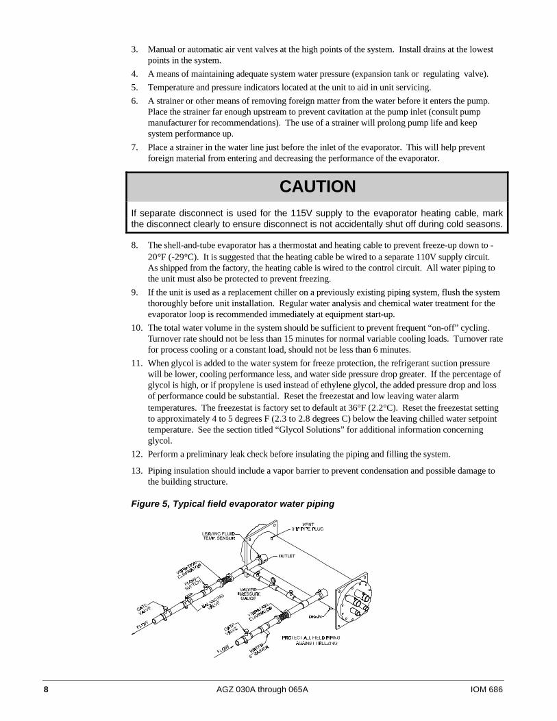
Figure 5, Typical field evaporator water piping
IOM 686 AGZ 030A through 065A 9
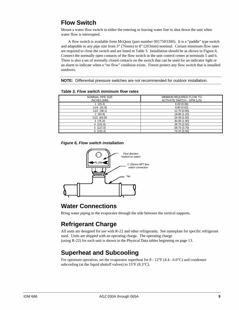
Flow SwitchMount a water flow switch in either the entering or leaving water line to shut down the unit whenwater flow is interrupted.
A flow switch is available from McQuay (part number 0017503300). It is a “paddle” type switchand adaptable to any pipe size from 3” (76mm) to 8” (203mm) nominal. Certain minimum flow ratesare required to close the switch and are listed in Table 3. Installation should be as shown in Figure 6.Connect the normally open contacts of the flow switch in the unit control center at terminals 5 and 6.There is also a set of normally closed contacts on the switch that can be used for an indicator light oran alarm to indicate when a “no flow” condition exists. Freeze protect any flow switch that is installedoutdoors.
NOTE: Differential pressure switches are not recommended for outdoor installation.
Table 3, Flow switch minimum flow ratesNOMINAL PIPE SIZE MINIMUM REQUIRED FLOW TO
INCHES (MM) ACTIVATE SWITCH - GPM (L/S)1 (25.4) 6.00 (0.38)
11/4 (31.8) 9.80 (0.62)11/2 (38.1) 12.70 (0.80)
2 (50.8) 18.80 (1.20)21/2 (63.50 24.30 (1.50)
3 (76.20 30.00 (1.90)4 (101.6) 39.70 (2.50)5 (127.0) 58.70 (3.70)6 (152.4) 79.20 (5.00)
Figure 6, Flow switch installation
Water ConnectionsBring water piping to the evaporator through the side between the vertical supports.
Refrigerant ChargeAll units are designed for use with R-22 and other refrigerants. See nameplate for specific refrigerantused. Units are shipped with an operating charge. The operating charge(using R-22) for each unit is shown in the Physical Data tables beginning on page 13.
Superheat and SubcoolingFor optimum operation, set the evaporator superheat for 8 - 12°F (4.4 - 6.6°C) and condensersubcooling (at the liquid shutoff valves) to 15°F (8.3°C).
Flow directionmarked on switch
1" (25mm) NPT flowswitch connection
Tee
10 AGZ 030A through 065A IOM 686
Glycol SolutionsThe system glycol capacity, glycol solution flow rate in GPM, and pressure drop through the coolermay be calculated using the following formulas and table.
1. Capacity -- Find the reduced capacity by multiplying the chiller’s capacity with water by thecapacity correction factor C.
2. Flow -- To determine evaporator gpm (or Delta-T) knowing Delta-T (or gpm) and capacity:
Glycol GPM (from table)=×
−×
24 capacity glycol
Delta TG
( )
For Metric Applications -- To determine evaporator L/s (or Delta-T) knowing Delta-T (or L/s)and kW:
Glycol L / s (from table)=× −
×kW
Delta TFlow
4.18
3. Pressure drop -- To determine pressure drop through the evaporator, when using glycol, enter thewater pressure drop curve on page 12 at the actual glycol GPM. Multiply the water pressure dropby PD correction factor from Table 4 or Table 5 to obtain corrected glycol pressure drop.
4. To determine the unit's power consumption when using glycol, multiply the water system kW byfactor kW.
Test coolant with a clean, accurate glycol solution hydrometer (similar to that found in servicestations) to determine the freezing point. Obtain percent glycol from the freezing point table below.On glycol applications it is normally recommended by the supplier that a minimum of 25% solution byweight be used for protection against corrosion.
CAUTIONDo not use an automotive grade antifreeze. Industrial grade glycols must be used.Automotive antifreeze contains inhibitors which will cause plating on the copper tubes withinthe chiller evaporator. The type and handling of glycol used must be consistent with localcodes.
Table 4, Ethylene glycol% Freeze Point
E.G. °F °C Cap. kW GPM PD10 26 -3 0.991 0.996 1.013 1.07020 18 -8 0.982 0.992 1.040 1.12930 7 -14 0.972 0.986 1.074 1.18140 -7 -22 0.961 0.976 1.121 1.26350 -28 -33 0.946 0.966 1.178 1.308
Table 5, Propylene glycol% Freeze Point
P.G. °F °C Cap. kW GPM PD10 26 -3 0.987 0.992 1.010 1.06820 19 -7 0.975 0.985 1.028 1.14730 9 -13 0.962 0.978 1.050 1.24840 -5 -21 0.946 0.971 1.078 1.36650 -27 -33 0.929 0.965 1.116 1.481
Note: The proceduredoes not specify thetype of glycol. Usethe derate factorsfound in Table 4 forcorrections whenusing ethylene glycoland those in Table 5for propylene glycol.

IOM 686 AGZ 030A through 065A 11
Table 6, Capacity and power deratesChilled Water Fouling Factor
Delta-T 0.00025 (0.044) 0.00075 (0.132) 0.00175 (0.308)ALTITUDE °F °C Cap. kW Cap. kW Cap. kW
6 3.3 0.992 0.995 0.996 0.982 0.911 0.9358 4.4 0.995 0.997 0.969 0.984 0.914 0.937
SEA 10 5.6 1.000 1.000 0.975 0.986 0.919 0.939LEVEL 12 6.7 1.005 1.002 0.980 0.989 0.923 0.941
14 6.8 1.010 1.005 0.985 0.991 0.928 0.94316 8.9 1.014 1.007 0.989 0.993 0.930 0.9446 3.3 0.978 1.005 0.957 0.990 0.903 0.9438 4.4 0.982 1.007 0.961 0.993 0.905 0.94510 5.6 0.986 1.009 0.965 0.995 0.909 0.947
2000 feet 12 6.7 0.992 1.011 0.970 0.998 0.914 0.94914 6.8 0.997 1.014 0.973 1.001 0.919 0.95216 8.9 1.000 1.016 0.975 1.002 0.921 0.9536 3.3 0.966 1.016 0.944 0.999 0.894 0.9518 4.4 0.969 1.018 0.947 1.001 0.896 0.95310 5.6 0.973 1.021 0.952 1.005 0.900 0.956
4000 feet 12 6.7 0.978 1.025 0.956 1.008 0.904 0.95814 6.8 0.982 1.027 0.959 1.011 0.909 0.96016 8.9 0.986 1.028 0.961 1.015 0.911 0.9616 3.3 0.953 1.025 0.930 1.009 0.884 0.9618 4.4 0.955 1.028 0.934 1.011 0.887 0.96210 5.6 0.959 1.031 0.939 1.013 0.890 0.964
6000 feet 12 6.7 0.963 1.034 0.942 1.017 0.895 0.96614 6.8 0.968 1.036 0.946 1.020 0.899 0.96816 8.9 0.972 1.037 0.949 1.024 0.902 0.969
Evaporator Water Flow and Pressure DropEvaporator flow rate must fall between the minimum and maximum values shown in the evaporatorpressure drop table on page 12.
Measure the chilled water pressure drop through the evaporator at factory installed pressure taps.It is important not to include the effect of valves or strainers in these readings.
Varying chilled water flow through the evaporator while the compressor(s) are operating is notrecommended.

12 AGZ 030A through 065A IOM 686
Figure 7, Pressure Drop Curve
045A - 065A030A - 040A
NOMINAL MAXIMUM MINIMUMPressure Drop Flow Pressure Drop Flow Pressure Drop Flow
Unit (ft) of water KPa (GPM) (L / s) (ft) ofWater
KPa (GPM) (L / s) (ft) of water KPa (GPM) KPa
030A 6.6 12.9 73.00 4.61 16.6 49.7 122.00 7.70 2.9 8.6 46.00 2.90035A 8.3 24.8 82.00 5.17 20.6 61.7 136.00 8.58 3.5 10.6 51.00 3.22040A 10.4 31.1 93.00 5.87 26.1 78.0 155.00 9.78 4.4 13.3 58.00 3.66045A 6.8 20.3 106.00 6.69 16.9 50.6 176.00 11.10 2.9 8.7 66.00 4.16050A 8.0 23.9 117.00 7.38 20.1 60.0 195.00 12.30 3.4 10.2 73.00 4.61055A 10.2 30.5 130.00 8.20 25.4 76.0 216.00 13.63 4.3 12.7 80.00 5.05060A 12.2 36.5 141.00 8.90 30.6 91.5 235.00 14.83 5.2 15.6 88.00 5.55065A 14.0 41.8 148.00 9.34 35.2 105.2 247.00 15.58 5.9 17.8 92.00 5.80
Minimum and maximum flows are established to ensure the Delta-T for each unit size falls within the 6 - 16°F range for proper unit control.
IOM 686 AGZ 030A through 065A 13
Physical Data
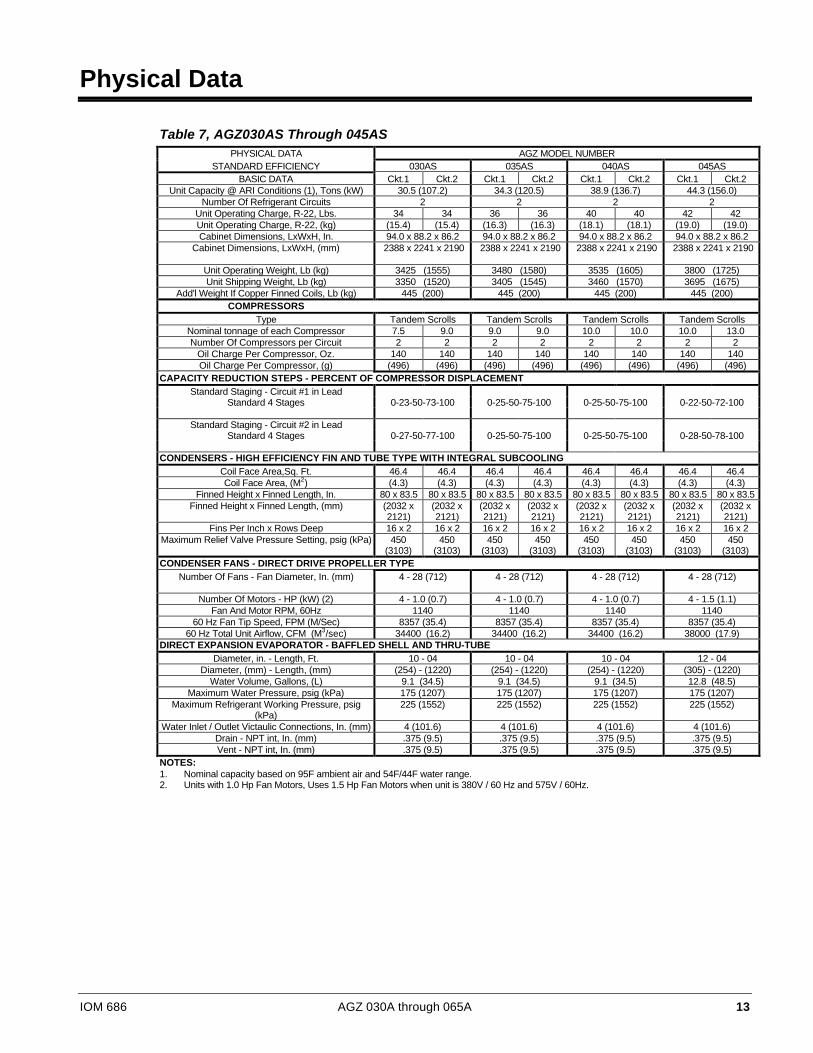
Table 7, AGZ030AS Through 045ASPHYSICAL DATA AGZ MODEL NUMBER
STANDARD EFFICIENCY 030AS 035AS 040AS 045ASBASIC DATA Ckt.1 Ckt.2 Ckt.1 Ckt.2 Ckt.1 Ckt.2 Ckt.1 Ckt.2
Unit Capacity @ ARI Conditions (1), Tons (kW) 30.5 (107.2) 34.3 (120.5) 38.9 (136.7) 44.3 (156.0)Number Of Refrigerant Circuits 2 2 2 2
Unit Operating Charge, R-22, Lbs. 34 34 36 36 40 40 42 42Unit Operating Charge, R-22, (kg) (15.4) (15.4) (16.3) (16.3) (18.1) (18.1) (19.0) (19.0)Cabinet Dimensions, LxWxH, In. 94.0 x 88.2 x 86.2 94.0 x 88.2 x 86.2 94.0 x 88.2 x 86.2 94.0 x 88.2 x 86.2
Cabinet Dimensions, LxWxH, (mm) 2388 x 2241 x 2190 2388 x 2241 x 2190 2388 x 2241 x 2190 2388 x 2241 x 2190
Unit Operating Weight, Lb (kg) 3425 (1555) 3480 (1580) 3535 (1605) 3800 (1725)Unit Shipping Weight, Lb (kg) 3350 (1520) 3405 (1545) 3460 (1570) 3695 (1675)
Add'l Weight If Copper Finned Coils, Lb (kg) 445 (200) 445 (200) 445 (200) 445 (200)COMPRESSORS
Type Tandem Scrolls Tandem Scrolls Tandem Scrolls Tandem ScrollsNominal tonnage of each Compressor 7.5 9.0 9.0 9.0 10.0 10.0 10.0 13.0Number Of Compressors per Circuit 2 2 2 2 2 2 2 2
Oil Charge Per Compressor, Oz. 140 140 140 140 140 140 140 140Oil Charge Per Compressor, (g) (496) (496) (496) (496) (496) (496) (496) (496)
CAPACITY REDUCTION STEPS - PERCENT OF COMPRESSOR DISPLACEMENTStandard Staging - Circuit #1 in Lead
Standard 4 Stages 0-23-50-73-100 0-25-50-75-100 0-25-50-75-100 0-22-50-72-100
Standard Staging - Circuit #2 in LeadStandard 4 Stages 0-27-50-77-100 0-25-50-75-100 0-25-50-75-100 0-28-50-78-100
CONDENSERS - HIGH EFFICIENCY FIN AND TUBE TYPE WITH INTEGRAL SUBCOOLINGCoil Face Area,Sq. Ft. 46.4 46.4 46.4 46.4 46.4 46.4 46.4 46.4Coil Face Area, (M2) (4.3) (4.3) (4.3) (4.3) (4.3) (4.3) (4.3) (4.3)
Finned Height x Finned Length, In. 80 x 83.5 80 x 83.5 80 x 83.5 80 x 83.5 80 x 83.5 80 x 83.5 80 x 83.5 80 x 83.5Finned Height x Finned Length, (mm) (2032 x
2121)(2032 x2121)
(2032 x2121)
(2032 x2121)
(2032 x2121)
(2032 x2121)
(2032 x2121)
(2032 x2121)
Fins Per Inch x Rows Deep 16 x 2 16 x 2 16 x 2 16 x 2 16 x 2 16 x 2 16 x 2 16 x 2Maximum Relief Valve Pressure Setting, psig (kPa) 450
(3103)450
(3103)450
(3103)450
(3103)450
(3103)450
(3103)450
(3103)450
(3103)CONDENSER FANS - DIRECT DRIVE PROPELLER TYPE
Number Of Fans - Fan Diameter, In. (mm) 4 - 28 (712) 4 - 28 (712) 4 - 28 (712) 4 - 28 (712)
Number Of Motors - HP (kW) (2) 4 - 1.0 (0.7) 4 - 1.0 (0.7) 4 - 1.0 (0.7) 4 - 1.5 (1.1)Fan And Motor RPM, 60Hz 1140 1140 1140 1140
60 Hz Fan Tip Speed, FPM (M/Sec) 8357 (35.4) 8357 (35.4) 8357 (35.4) 8357 (35.4)60 Hz Total Unit Airflow, CFM (M3/sec) 34400 (16.2) 34400 (16.2) 34400 (16.2) 38000 (17.9)
DIRECT EXPANSION EVAPORATOR - BAFFLED SHELL AND THRU-TUBEDiameter, in. - Length, Ft. 10 - 04 10 - 04 10 - 04 12 - 04
Diameter, (mm) - Length, (mm) (254) - (1220) (254) - (1220) (254) - (1220) (305) - (1220)Water Volume, Gallons, (L) 9.1 (34.5) 9.1 (34.5) 9.1 (34.5) 12.8 (48.5)
Maximum Water Pressure, psig (kPa) 175 (1207) 175 (1207) 175 (1207) 175 (1207)Maximum Refrigerant Working Pressure, psig
(kPa)225 (1552) 225 (1552) 225 (1552) 225 (1552)
Water Inlet / Outlet Victaulic Connections, In. (mm) 4 (101.6) 4 (101.6) 4 (101.6) 4 (101.6)Drain - NPT int, In. (mm) .375 (9.5) .375 (9.5) .375 (9.5) .375 (9.5)Vent - NPT int, In. (mm) .375 (9.5) .375 (9.5) .375 (9.5) .375 (9.5)
NOTES:1. Nominal capacity based on 95F ambient air and 54F/44F water range.2. Units with 1.0 Hp Fan Motors, Uses 1.5 Hp Fan Motors when unit is 380V / 60 Hz and 575V / 60Hz.
14 AGZ 030A through 065A IOM 686
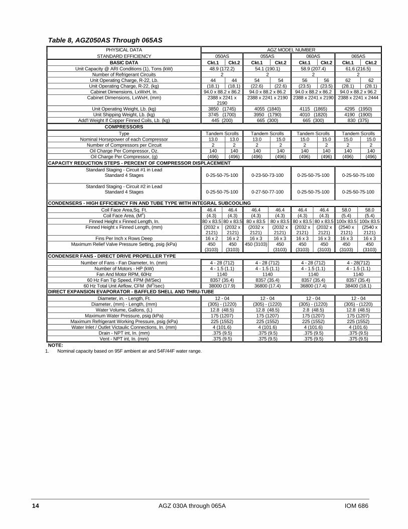
Table 8, AGZ050AS Through 065ASPHYSICAL DATA AGZ MODEL NUMBER
STANDARD EFFICIENCY 050AS 055AS 060AS 065ASBASIC DATA Ckt.1 Ckt.2 Ckt.1 Ckt.2 Ckt.1 Ckt.2 Ckt.1 Ckt.2
Unit Capacity @ ARI Conditions (1), Tons (kW) 48.9 (172.2) 54.1 (190.1) 58.9 (207.4) 61.6 (216.5)Number of Refrigerant Circuits 2 2 2 2
Unit Operating Charge, R-22, Lb. 44 44 54 54 56 56 62 62Unit Operating Charge, R-22, (kg) (18.1) (18.1) (22.6) (22.6) (23.5) (23.5) (28.1) (28.1)Cabinet Dimensions, LxWxH, In. 94.0 x 88.2 x 86.2 94.0 x 88.2 x 86.2 94.0 x 88.2 x 86.2 94.0 x 88.2 x 96.2
Cabinet Dimensions, LxWxH, (mm) 2388 x 2241 x2190
2388 x 2241 x 2190 2388 x 2241 x 2190 2388 x 2241 x 2444
Unit Operating Weight, Lb. (kg) 3850 (1745) 4055 (1840) 4115 (1865) 4295 (1950)Unit Shipping Weight, Lb. (kg) 3745 (1700) 3950 (1790) 4010 (1820) 4190 (1900)
Add'l Weight If Copper Finned Coils, Lb. (kg) 445 (200) 665 (300) 665 (300) 830 (375)COMPRESSORS
Type Tandem Scrolls Tandem Scrolls Tandem Scrolls Tandem ScrollsNominal Horsepower of each Compressor 13.0 13.0 13.0 15.0 15.0 15.0 15.0 15.0
Number of Compressors per Circuit 2 2 2 2 2 2 2 2Oil Charge Per Compressor, Oz. 140 140 140 140 140 140 140 140Oil Charge Per Compressor, (g) (496) (496) (496) (496) (496) (496) (496) (496)
CAPACITY REDUCTION STEPS - PERCENT OF COMPRESSOR DISPLACEMENTStandard Staging - Circuit #1 in Lead
Standard 4 Stages 0-25-50-75-100 0-23-50-73-100 0-25-50-75-100 0-25-50-75-100
Standard Staging - Circuit #2 in LeadStandard 4 Stages 0-25-50-75-100 0-27-50-77-100 0-25-50-75-100 0-25-50-75-100
CONDENSERS - HIGH EFFICIENCY FIN AND TUBE TYPE WITH INTEGRAL SUBCOOLINGCoil Face Area,Sq. Ft. 46.4 46.4 46.4 46.4 46.4 46.4 58.0 58.0Coil Face Area, (M2) (4.3) (4.3) (4.3) (4.3) (4.3) (4.3) (5.4) (5.4)
Finned Height x Finned Length, In. 80 x 83.5 80 x 83.5 80 x 83.5 80 x 83.5 80 x 83.5 80 x 83.5 100x 83.5 100x 83.5Finned Height x Finned Length, (mm) (2032 x
2121)(2032 x2121)
(2032 x2121)
(2032 x2121)
(2032 x2121)
(2032 x2121)
(2540 x2121)
(2540 x2121)
Fins Per Inch x Rows Deep 16 x 2 16 x 2 16 x 3 16 x 3 16 x 3 16 x 3 16 x 3 16 x 3Maximum Relief Valve Pressure Setting, psig (kPa) 450
(3103)450
(3103)450 (3103) 450
(3103)450
(3103)450
(3103)450
(3103)450
(3103)CONDENSER FANS - DIRECT DRIVE PROPELLER TYPE
Number of Fans - Fan Diameter, In. (mm) 4 - 28 (712) 4 - 28 (712) 4 - 28 (712) 4 - 28(712)Number of Motors - HP (kW) 4 - 1.5 (1.1) 4 - 1.5 (1.1) 4 - 1.5 (1.1) 4 - 1.5 (1.1)Fan And Motor RPM, 60Hz 1140 1140 1140 1140
60 Hz Fan Tip Speed, FPM (M/Sec) 8357 (35.4) 8357 (35.4) 8357 (35.4) 8357 (35.4)60 Hz Total Unit Airflow, CFM (M3/sec) 38000 (17.9) 36800 (17.4) 36800 (17.4) 38400 (18.1)
DIRECT EXPANSION EVAPORATOR - BAFFLED SHELL AND THRU-TUBEDiameter, in. - Length, Ft. 12 - 04 12 - 04 12 - 04 12 - 04
Diameter, (mm) - Length, (mm) (305) - (1220) (305) - (1220) (305) - (1220) (305) - (1220)Water Volume, Gallons, (L) 12.8 (48.5) 12.8 (48.5) 2.8 (48.5) 12.8 (48.5)
Maximum Water Pressure, psig (kPa) 175 (1207) 175 (1207) 175 (1207) 175 (1207)Maximum Refrigerant Working Pressure, psig (kPa) 225 (1552) 225 (1552) 225 (1552) 225 (1552)Water Inlet / Outlet Victaulic Connections, In. (mm) 4 (101.6) 4 (101.6) 4 (101.6) 4 (101.6)
Drain - NPT int, In. (mm) .375 (9.5) .375 (9.5) .375 (9.5) .375 (9.5)Vent - NPT int, In. (mm) .375 (9.5) .375 (9.5) .375 (9.5) .375 (9.5)
NOTE:1. Nominal capacity based on 95F ambient air and 54F/44F water range.
IOM 686 AGZ 030A through 065A 15
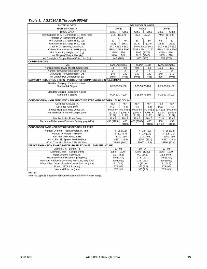
Table 9, AGZ030AE Through 050AEPHYSICAL DATA AGZ MODEL NUMBER
HIGH EFFICIENCY 030AE 040AE 050AEBASIC DATA Ckt.1 Ckt.2 Ckt.1 Ckt.2 Ckt.1 Ckt.2
Unit Capacity @ ARI Conditions (1), Tons (kW) 31.5 (110.7) 39.2 (137.7) 49.2 (172.8)Number Of Refrigerant Circuits 2 2 2
Unit Operating Charge, R-22, Lbs. 40 40 50 50 52 52Unit Operating Charge, R-22, (kg) (16.3) (16.3) (22.6) (22.6) (23.5) (23.5)Cabinet Dimensions, LxWxH, In. 94.0 x 88.2 x 86.2 94.0 x 88.2 x 86.2 94.0 x 88.2 x 86.2
Cabinet Dimensions, LxWxH, (mm) 2388 x 2241 x 2190 2388 x 2241 x 2190 2388 x 2241 x 2190Unit Operating Weight, Lbs. (kg) 3485 (1580) 3695 (1675) 4010 (1820)Unit Shipping Weight, Lbs. (kg) 3410 (1545) 3620 (1640) 3905 (1770)
Add'l Weight If Copper Finned Coils, Lbs. (kg) 445 (200) 665 (300) 830 (375)COMPRESSORS
Type Tandem Scrolls Tandem Scrolls Tandem ScrollsNominal Horsepower of each Compressor 7.5 9.0 9.0 9.0 10.0 10.0
Number Of Compressors per Circuit 2 2 2 2 2 2Oil Charge Per Compressor, Oz. 140 140 140 140 140 140Oil Charge Per Compressor, (g) (496) (496) (496) (496) (496) (496)
CAPACITY REDUCTION STEPS - PERCENT OF COMPRESSOR DISPLACEMENTStandard Staging - Circuit #1 in Lead
Standard 4 Stages 0-23-50-73-100 0-25-50-75-100 0-25-50-75-100
Standard Staging - Circuit #2 in LeadStandard 4 Stages 0-27-50-77-100 0-25-50-75-100 0-25-50-75-100
CONDENSERS - HIGH EFFICIENCY FIN AND TUBE TYPE WITH INTEGRAL SUBCOOLINGCoil Face Area,Sq. Ft. 46.4 46.4 46.4 46.4 46.4 46.4Coil Face Area, (M2) (4.3) (4.3) (4.3) (4.3) (4.3) (4.3)
Finned Height x Finned Length, In. 80 x 83.5 80 x 83.5 80 x 83.5 80 x 83.5 80 x 83.5 80 x 83.5Finned Height x Finned Length, (mm) (2032 x
2121)(2032 x2121)
(2032 x2121)
(2032 x2121)
(2032 x2121)
(2032 x2121)
Fins Per Inch x Rows Deep 16 x 2 16 x 2 16 x 3 16 x 3 16 x 3 16 x 3Maximum Relief Valve Pressure Setting, psig (kPa) 450 (3103) 450
(3103)450 (3103) 450
(3103)450
(3103)450
(3103)CONDENSER FANS - DIRECT DRIVE PROPELLER TYPE
Number Of Fans - Fan Diameter, In. (mm) 4 - 28 (712) 4 - 28 (712) 4 - 28 (712)Number Of Motors - HP (kW) 4 - 1.0 (0.7) 4 - 1.0 (0.7) 4 - 1.5 (1.1)Fan And Motor RPM, 60Hz 1140 / 950 1140 / 950 1140 / 950
60 Hz Fan Tip Speed, FPM (M/Sec) 8357 (35.4) 8357 (35.4) 8357 (35.4)60 Hz Total Unit Airflow, CFM (M3/sec) 34400 (16.2) 33600 (15.9) 36800 (17.4)
DIRECT EXPANSION EVAPORATOR - BAFFLED SHELL AND THRU-TUBEDiameter, in. - Length, Ft. 10 - 04 10 - 04 12 - 04
Diameter, (mm) - Length, (mm) (254) - (1220) (254) - (1220) (305) - (1220)Water Volume, Gallons, (L) 9.1 (34.5) 9.1 (34.5) 12.8 (48.5)
Maximum Water Pressure, psig (kPa) 175 (1207) 175 (1207) 175 (1207)Maximum Refrigerant Working Pressure, psig (kPa) 225 (1552) 225 (1552) 225 (1552)Water Inlet / Outlet Victaulic Connections, In. (mm) 4 (101.6) 4 (101.6) 4 (101.6)
Drain - NPT int, In. (mm) .375 (9.5) .375 (9.5) .375 (9.5)Vent - NPT int, In. (mm) .375 (9.5) .375 (9.5) .375 (9.5)
NOTE:Nominal capacity based on 95F ambient air and 54F/44F water range.

16 AGZ 030A through 065A IOM 686
Electrical Data
Field Wiring
CAUTIONInternal power wiring to the compressors for single and multiple point option are different.Field wiring must be installed according to unit wiring diagram.
Wiring must comply with all applicable codes and ordinances. Warranty is void if wiring is not inaccordance with specifications. Copper wire is required for all power lead terminations at the unit.Aluminum or copper can be used for all other wiring.
AGZ units have internal power wiring for single point power connection. A single large powerterminal block is provided and wiring within the unit is sized in accordance with the NationalElectrical Code. A single field supplied fused disconnect is required. An optional factory mountedtransformer may be installed.
If the evaporator heater is on a separate disconnect switch from the main unit power supply, theunit may be shut down without defeating the freeze protection provided by the cooler heater.
Table 10, AGZ030A - 065A, 60 Hz, Single Point Power Electrical DataMinimum POWER SUPPLY Max. Fuse
AGZ Circuit Field Wire Hub orUnit Volts Ampacity Wire Nominal HACR
BreakerSize (MCA) Quantity Gauge Quantity Size Size
208 129 3 1 1 1.25 (32) 150230 129 3 1 1 1.25 (32) 150
030AS 380 86 3 3 1 1.25 (32) 100030AE 460 68 3 4 1 1.00 (25) 80
575 53 3 6 1 1.00 (25) 60208 143 3 1/0 1 1.50 (38) 150230 143 3 1/0 1 1.50 (38) 150
035AS 380 93 3 3 1 1.25 (32) 110460 73 3 4 1 1.00 (25) 80575 58 3 4 1 1.00 (25) 70208 159 3 2/0 1 1.50 (38) 175230 159 3 2/0 1 1.50 (38) 175
040AS 380 111 3 2 1 1.25 (32) 125040AE 460 78 3 3 1 1.25 (32) 90
575 67 3 4 1 1.00 (25) 80208 180 3 3/0 1 2.00 (51) 175230 180 3 3/0 1 2.00 (51) 175
045AS 380 123 3 1 1 1.25 (32) 150460 88 3 2 1 1.25 (32) 90575 76 3 3 1 1.25 (32) 80208 191 3 3/0 1 2.00 (51) 225230 191 3 3/0 1 2.00 (51) 225
050AS 380 134 3 1/0 1 1.50 (38) 150050AE 460 94 3 2 1 1.25 (32) 110
575 83 3 3 1 1.25 (32) 100208 221 3 4/0 1 2.00 (51) 250230 221 3 4/0 1 2.00 (51) 250
055AS 380 148 3 1/0 1 1.50 (38) 175460 103 3 2 1 1.25 (32) 125575 87 3 2 1 1.25 (32) 100208 247 3 250 1 2.50 (64) 250230 247 3 250 1 2.50 (64) 250
060AS 380 161 3 2/0 1 1.50 (38) 175460 112 3 2 1 1.25 (32) 125575 90 3 2 1 1.25 (32) 100208 247 3 250 1 2.50 (64) 250230 247 3 250 1 2.50 (64) 250
065AS 380 161 3 2/0 1 1.50 (38) 175460 112 3 2 1 1.25 (32) 125575 90 3 2 1 1.25 (32) 100

IOM 686 AGZ 030A through 065A 17
Table 11, AGZ030A - 065A, 60 Hz, Compressor and Condenser Fan Motor Amp DrawRated Load Amps Locked Rotor Amps
AGZ Compressors No. Of CompressorsUnit Volts No. No. Fan Fan Fan Across-The-LineSize 1 & 3 2 & 4 Motors Motors Motors No.1 & 3 No.2 & 4
(Each) (Each) (Each) (Each) (Each) (Each)208 22.9 29.9 4.0 4 17.0 169 232230 22.9 29.9 4.0 4 17.0 189 232
030AS 380 14.9 18.6 3.4 4 14.4 112 144030AE 460 12.5 15.3 2.0 4 8.5 94 116
575 9.1 11.6 2.2 4 10.3 74 97208 29.9 29.9 4.0 4 17.0 232 232230 29.9 29.9 4.0 4 17.0 232 232
035AS 380 18.6 18.6 3.4 4 14.4 144 144460 15.3 15.3 2.0 4 8.5 116 116575 11.6 11.6 2.2 4 10.3 97 97208 33.6 33.6 4.0 4 17.0 255 255230 33.6 33.6 4.0 4 17.0 255 255
040AS 380 22.8 22.8 3.4 4 14.4 151 151040AE 460 16.4 16.4 2.0 4 8.5 127 127
575 13.7 13.7 2.2 4 10.3 100 100208 33.6 39.5 5.8 4 23.7 255 318230 33.6 39.5 5.8 4 23.7 255 318
045AS 380 22.8 28.2 3.4 4 14.4 151 188460 16.4 19.3 2.8 4 10.7 127 158575 13.7 17.3 2.3 4 11.5 100 125208 39.5 39.5 5.8 4 23.7 318 318230 39.5 39.5 5.8 4 23.7 318 318
050AS 380 28.2 28.2 3.4 4 14.4 188 188050AE 460 19.3 19.3 2.8 4 10.7 158 158
575 17.3 17.3 2.3 4 11.5 125 125208 39.5 52.6 5.8 4 23.7 318 411230 39.5 52.6 5.8 4 23.7 318 411
055AS 380 28.2 34.6 3.4 4 14.4 188 249460 19.3 23.7 2.8 4 10.7 158 187575 17.3 19.0 2.3 4 11.5 125 150208 52.6 52.6 5.8 4 23.7 411 411230 52.6 52.6 5.8 4 23.7 411 411
060AS 380 34.6 34.6 3.4 4 14.4 249 249460 23.7 23.7 2.8 4 10.7 187 187575 19.0 19.0 2.3 4 11.5 150 150208 52.6 52.6 5.8 4 23.7 411 411230 52.6 52.6 5.8 4 23.7 411 411
065AS 380 34.6 34.6 3.4 4 14.4 249 249460 23.7 23.7 2.8 4 10.7 187 187575 19.0 19.0 2.3 4 11.5 150 150
Table 12, AGZ030A - 065A, 60 Hz Single Point Power, Field Wiring DataWiring to Standard Wiring to Optional
AGZ Power Block Non-Fused Disconnect SwitchUnit Volts Terminal Connector Wire Range Terminal Connector Wire RangeSize Amps (Copper Wire Only) Amps (Copper Wire Only)
208 175 #12 - 2/0 225 # 3 - 300 MCM230 175 #12 - 2/0 225 # 3 - 300 MCM
030AS 380 175 #12 - 2/0 100 #14 - 1/0030AE 460 175 #12 - 2/0 100 #14 - 1/0
575 175 #12 - 2/0 100 #14 - 1/0208 175 #12 - 2/0 225 # 3 - 300 MCM230 175 #12 - 2/0 225 # 3 - 300 MCM
035AS 380 175 #12 - 2/0 100 #14 - 1/0460 175 #12 - 2/0 100 #14 - 1/0575 175 #12 - 2/0 100 #14 - 1/0208 175 #12 - 2/0 225 # 3 - 300 MCM230 175 #12 - 2/0 225 # 3 - 300 MCM
040AS 380 175 #12 - 2/0 150 #4 - 4/0040AE 460 175 #12 - 2/0 100 #14 - 1/0
575 175 #12 - 2/0 100 #14 - 1/0208 335 # 4 - 400 MCM 225 # 3 - 300 MCM230 335 # 4 - 400 MCM 225 # 3 - 300 MCM
045AS 380 175 #12 - 2/0 150 #4 - 4/0460 175 #12 - 2/0 100 #14 - 1/0575 175 #12 - 2/0 100 #14 - 1/0
Table continued on next page
18 AGZ 030A through 065A IOM 686
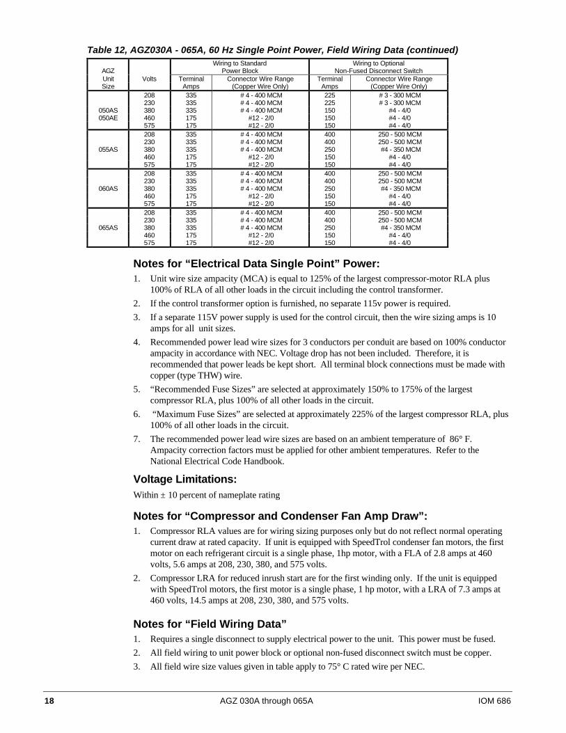
Table 12, AGZ030A - 065A, 60 Hz Single Point Power, Field Wiring Data (continued)Wiring to Standard Wiring to Optional
AGZ Power Block Non-Fused Disconnect SwitchUnit Volts Terminal Connector Wire Range Terminal Connector Wire RangeSize Amps (Copper Wire Only) Amps (Copper Wire Only)
208 335 # 4 - 400 MCM 225 # 3 - 300 MCM230 335 # 4 - 400 MCM 225 # 3 - 300 MCM
050AS 380 335 # 4 - 400 MCM 150 #4 - 4/0050AE 460 175 #12 - 2/0 150 #4 - 4/0
575 175 #12 - 2/0 150 #4 - 4/0208 335 # 4 - 400 MCM 400 250 - 500 MCM230 335 # 4 - 400 MCM 400 250 - 500 MCM
055AS 380 335 # 4 - 400 MCM 250 #4 - 350 MCM460 175 #12 - 2/0 150 #4 - 4/0575 175 #12 - 2/0 150 #4 - 4/0208 335 # 4 - 400 MCM 400 250 - 500 MCM230 335 # 4 - 400 MCM 400 250 - 500 MCM
060AS 380 335 # 4 - 400 MCM 250 #4 - 350 MCM460 175 #12 - 2/0 150 #4 - 4/0575 175 #12 - 2/0 150 #4 - 4/0208 335 # 4 - 400 MCM 400 250 - 500 MCM230 335 # 4 - 400 MCM 400 250 - 500 MCM
065AS 380 335 # 4 - 400 MCM 250 #4 - 350 MCM460 175 #12 - 2/0 150 #4 - 4/0575 175 #12 - 2/0 150 #4 - 4/0
Notes for “Electrical Data Single Point” Power:1. Unit wire size ampacity (MCA) is equal to 125% of the largest compressor-motor RLA plus
100% of RLA of all other loads in the circuit including the control transformer.
2. If the control transformer option is furnished, no separate 115v power is required.
3. If a separate 115V power supply is used for the control circuit, then the wire sizing amps is 10amps for all unit sizes.
4. Recommended power lead wire sizes for 3 conductors per conduit are based on 100% conductorampacity in accordance with NEC. Voltage drop has not been included. Therefore, it isrecommended that power leads be kept short. All terminal block connections must be made withcopper (type THW) wire.
5. “Recommended Fuse Sizes” are selected at approximately 150% to 175% of the largestcompressor RLA, plus 100% of all other loads in the circuit.
6. “Maximum Fuse Sizes” are selected at approximately 225% of the largest compressor RLA, plus100% of all other loads in the circuit.
7. The recommended power lead wire sizes are based on an ambient temperature of 86° F.Ampacity correction factors must be applied for other ambient temperatures. Refer to theNational Electrical Code Handbook.
Voltage Limitations:Within ± 10 percent of nameplate rating
Notes for “Compressor and Condenser Fan Amp Draw”:1. Compressor RLA values are for wiring sizing purposes only but do not reflect normal operating
current draw at rated capacity. If unit is equipped with SpeedTrol condenser fan motors, the firstmotor on each refrigerant circuit is a single phase, 1hp motor, with a FLA of 2.8 amps at 460volts, 5.6 amps at 208, 230, 380, and 575 volts.
2. Compressor LRA for reduced inrush start are for the first winding only. If the unit is equippedwith SpeedTrol motors, the first motor is a single phase, 1 hp motor, with a LRA of 7.3 amps at460 volts, 14.5 amps at 208, 230, 380, and 575 volts.
Notes for “Field Wiring Data”1. Requires a single disconnect to supply electrical power to the unit. This power must be fused.
2. All field wiring to unit power block or optional non-fused disconnect switch must be copper.
3. All field wire size values given in table apply to 75° C rated wire per NEC.

IOM 686 AGZ 030A through 065A 19
Figure 8, Typical Field Wiring with Global UNT Controller
UNIT MAINTERMINAL BLOCK
DISCONNECT(BY OTHERS)
3 PHASE
POWER
SUPPLY
GND LUG
TO COMPRESSOR(S)AND FAN MOTORS
FUSED CONTROLCIRCUIT TRANSFORMER
OPTION
10AFUSE
N
NB
TB2
10AFUSE
1(BY OTHERS)
(BY OTHERS)(BY OTHERS)N
SEPARATE EVAPORATORHEATER POWER
OPTION
DISCONNECT
DISCONNECT
(BY OTHERS)
(BY OTHERS)
13
16
545IF SEPARATE EVAPORATOR
HEATER POWER OPTIONIS USED - REMOVE
WIRES 540 AND 545.
120VACCONTROL POWER
120VAC
TB3
19
28
FACTORY SUPPLIED ALARMFIELD WIRED
ALARM BELLALARM BELL
OPTION24VAC
GND
TB7
140
141
AUTOOFF
MANUAL
ON
TIMECLOCK
AMBIENTTHERMOSTAT
REMOTE STOP(BY OTHERS)
CHW FLOW SWITCH(BY OTHERS)
142
143
133
134
135
MJ
SEE OPTIONS BELOW(ONLY ONE SELECTION
AVAIL. AT A TIME.)
IF REMOTE STOP CONTROLOR TIME CLOCK
IS USED, REMOVE JUMPERFROM TERM 140 TO 141.
2540
CONTROLCIRCUIT
FUSE
0-10V-DEMAND LIMITTEMP.-ZONE TEMP.2-10V-REMOTE RESETTEMP.-RETURN EVAP. WATERTEMP.-*OUTSIDE AIR
*STANDARD SELECTION
120 VAC
TIME DELAY

20 AGZ 030A through 065A IOM 686
Figure 9, Typical Field Wiring Diagram with MicroTech ControllerUNIT MAIN
TERMINAL BLOCKDISCONNECT(BY OTHERS)
3 PHASE
POWER
SUPPLY
GND LUG
TO COMPRESSOR(S)AND FAN MOTORS
FUSED CONTROLCIRCUIT TRANSFORMER
OPTION
10AFUSE
N
NB
TB2
10AFUSE
1(BY OTHERS)
(BY OTHERS)(BY OTHERS)
N
SEPARATE EVAPORATORHEATER POWER
OPTION
DISCONNECT
DISCONNECT
(BY OTHERS)
(BY OTHERS)
13
16
540
545IF SEPARATE EVAPORATOR
HEATER POWER OPTIONIS USED - REMOVE
WIRES 540 AND 545.
9
10
5A
24V OR 120VAC
120VACCONTROL POWER
120VAC
(BY OTHERS)
N
CHW PUMP RELAY(BY OTHERS)
SOLID STATE RELAY24V OR 120VAC1.5 AMPS MAX.
TB3
19
28
FACTORY SUPPLIED ALARMFIELD WIRED
ALARM BELLALARM BELL
OPTION24VAC
GND
TB7
140
141
AUTOOFF
MANUAL
ON
TIMECLOCK
AMBIENTTHERMOSTAT
REMOTE STOP(BY OTHERS)
CHW FLOW SWITCH(BY OTHERS)
142
143
134
135
133
132
131
4-20 MA FORCHW RESET
(BY OTHERS)
4-20 MA FORDEMAND LIMIT(BY OTHERS)
GND
137
138
139GND
3
4
5
COMMUNICATIONPORT "B"
MJIF REMOTE STOP CONTROLIS USED, REMOVE JUMPERFROM TERM 140 TO 141.
*(CONNECTION TO RMS(REMOTE MONITORING SEQUENCE)
OR TO NMP(NETWORK MASTER PANEL)
*MICROTECH ONLY
2
CONTROLCIRCUIT
FUSE
120 VAC
*

IOM 686 AGZ 030A through 065A 21
Figure 10, Single-point Connection with FanTrol

22 AGZ 030A through 065A IOM 686
Figure 11, Single-point Connection with SpeedTrol

,20 ��� $*= ���$ WKURXJK ���$ ��
)LJXUH ��� 8QLW &RQWURO 6FKHPDWLF �817�
24 AGZ 030A through 065A IOM 686
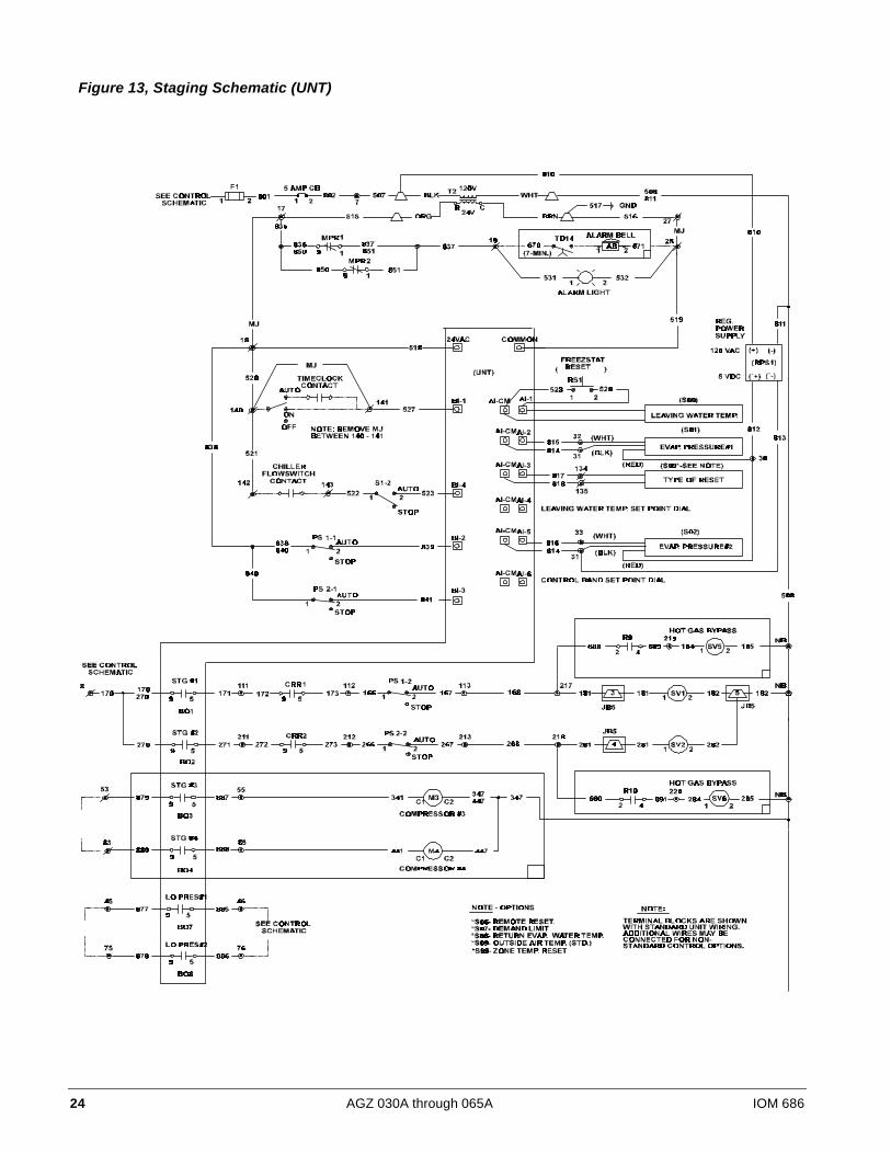
Figure 13, Staging Schematic (UNT)

IOM 686 AGZ 030A through 065A 25
Figure 14, MicroTech Controller Schematic
26 AGZ 030A through 065A IOM 686
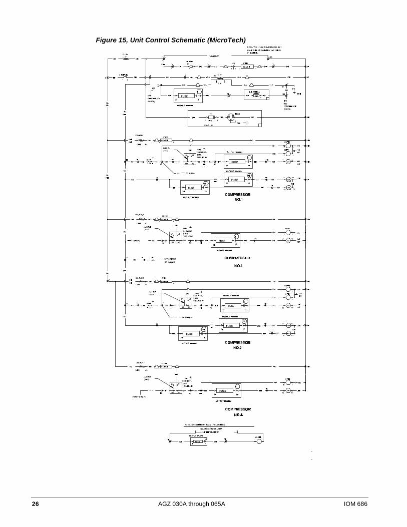
Figure 15, Unit Control Schematic (MicroTech)
IOM 686 AGZ 030A through 065A 27
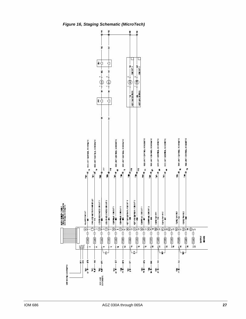
Figure 16, Staging Schematic (MicroTech)

28 AGZ 030A through 065A IOM 686
Dimensional Data
Figure 17, Dimensions AGZ 030A through 065A
AGZ Center of Gravity Additional WeightMODEL inch / mm for Units with CopperNumber A B C D E F X Y Z Operating Shipping Fin Coils lb / kg030AS 86.2
(2189.5)81.7
(2075.2)61.6
(1565.3)22.3
(566.4)5.3
(133.8)15.0
(381.0)43.9
(1115)40.2
(1021)35.9(912)
3425(1555)
3350(1520)
445(200)
030AE 86.2(2189.5)
81.7(2075.2)
61.6(1565.3)
22.3(566.4)
5.3(133.8)
15.0(381.0)
43.9(1115)
44.6(1133)
35.9(912)
3485(1580)
3410(1545)
445(200)
040AS 86.2(2189.5)
81.7(2075.2)
61.6(1565.3)
22.3(566.4)
5.3(133.8)
15.0(381.0)
43.9(1115)
44.6(1133)
36.2(920)
3480(1580)
3405(1545)
445(200)
040AE 86.2(2189.5)
81.7(2075.2)
61.6(1565.3)
22.3(566.4)
5.3(133.8)
15.0(381.0)
43.9(1115)
44.6(1133)
36.2(920)
3535(1605)
3460(1570)
445(200)
045AS 86.2(2189.5)
81.7(2075.2)
61.6(1565.3)
22.3(566.4)
5.3(133.8)
15.0(381.0)
43.9(1115)
44.6(1133)
37.4(950)
3695(1675)
3620(1640)
665(300)
050AS 86.2(2189.5)
81.7(2075.2)
60.0(1524.0)
24.0(609.6)
4.3(108.4)
16.0(406.4)
44.2(1123)
40.8(1036)
35.6(904)
3850(1745)
3745(1700)
445(200)
050AE 86.2(2189.5)
81.7(2075.2)
60.0(1524.0)
24.0(609.6)
4.3(108.4)
16.0(406.4)
44.6(1133)
41.2(1046)
37.4(950)
4010(1820)
3905(1770)
665(300)
055AS 86.2(2189.5)
81.7(2075.2)
60.0(1524.0)
24.0(609.6)
4.3(108.4)
16.0(406.4)
44.6(1133)
41.2(1046)
36.4(925)
4055(1840)
3950(1790)
665(300)
060AS 86.2(2189.5)
81.7(2075.2)
60.0(1524.0)
24.0(609.6)
4.3(108.4)
16.0(406.4)
44.6(1133)
41.2(1046)
36.4(925)
4115(1865)
4010(1820)
665(300)
065AE 96.2(2443.5)
91.7(2329.2)
60.0(1524.0)
24.0(609.6)
4.3(108.4)
16.0(406.4)
44.6(1133)
41.8(1062)
38.8(986)
4295(1950)
4190(1900)
830(375)
IOM 686 AGZ 030A through 065A 29
AGZ Unit Check-out
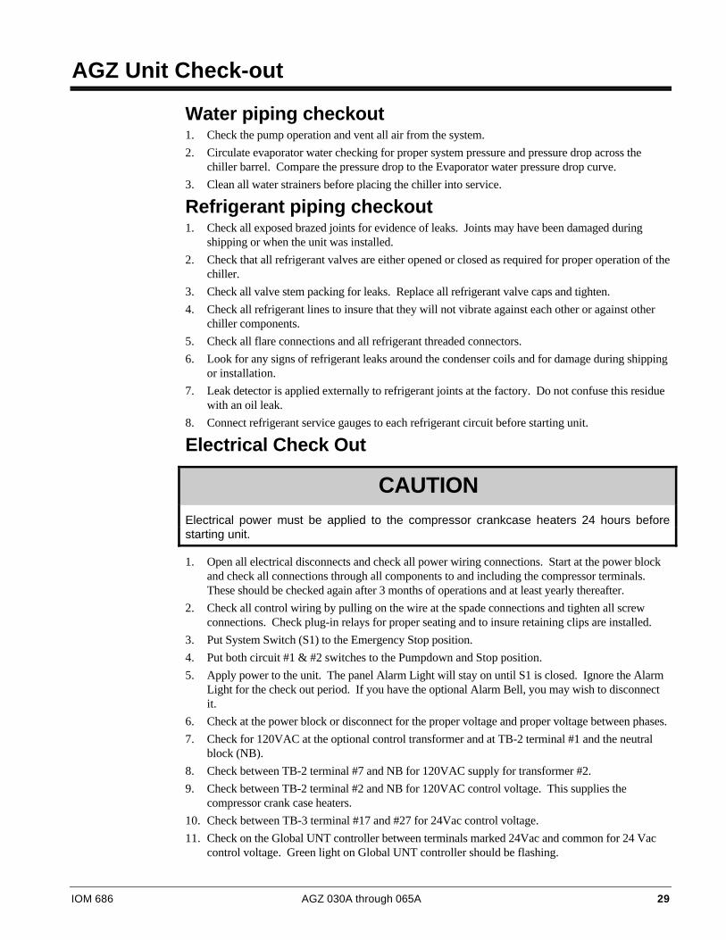
Water piping checkout1. Check the pump operation and vent all air from the system.
2. Circulate evaporator water checking for proper system pressure and pressure drop across thechiller barrel. Compare the pressure drop to the Evaporator water pressure drop curve.
3. Clean all water strainers before placing the chiller into service.
Refrigerant piping checkout1. Check all exposed brazed joints for evidence of leaks. Joints may have been damaged during
shipping or when the unit was installed.
2. Check that all refrigerant valves are either opened or closed as required for proper operation of thechiller.
3. Check all valve stem packing for leaks. Replace all refrigerant valve caps and tighten.
4. Check all refrigerant lines to insure that they will not vibrate against each other or against otherchiller components.
5. Check all flare connections and all refrigerant threaded connectors.
6. Look for any signs of refrigerant leaks around the condenser coils and for damage during shippingor installation.
7. Leak detector is applied externally to refrigerant joints at the factory. Do not confuse this residuewith an oil leak.
8. Connect refrigerant service gauges to each refrigerant circuit before starting unit.
Electrical Check Out
CAUTIONElectrical power must be applied to the compressor crankcase heaters 24 hours beforestarting unit.
1. Open all electrical disconnects and check all power wiring connections. Start at the power blockand check all connections through all components to and including the compressor terminals.These should be checked again after 3 months of operations and at least yearly thereafter.
2. Check all control wiring by pulling on the wire at the spade connections and tighten all screwconnections. Check plug-in relays for proper seating and to insure retaining clips are installed.
3. Put System Switch (S1) to the Emergency Stop position.
4. Put both circuit #1 & #2 switches to the Pumpdown and Stop position.
5. Apply power to the unit. The panel Alarm Light will stay on until S1 is closed. Ignore the AlarmLight for the check out period. If you have the optional Alarm Bell, you may wish to disconnectit.
6. Check at the power block or disconnect for the proper voltage and proper voltage between phases.
7. Check for 120VAC at the optional control transformer and at TB-2 terminal #1 and the neutralblock (NB).
8. Check between TB-2 terminal #7 and NB for 120VAC supply for transformer #2.
9. Check between TB-2 terminal #2 and NB for 120VAC control voltage. This supplies thecompressor crank case heaters.
10. Check between TB-3 terminal #17 and #27 for 24Vac control voltage.
11. Check on the Global UNT controller between terminals marked 24Vac and common for 24 Vaccontrol voltage. Green light on Global UNT controller should be flashing.
30 AGZ 030A through 065A IOM 686
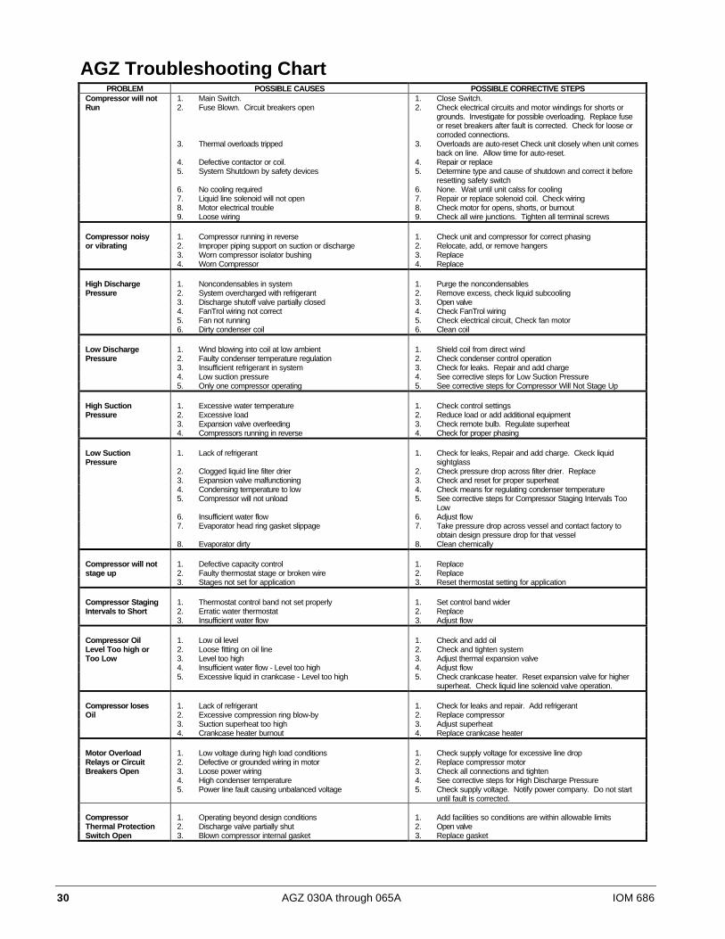
AGZ Troubleshooting ChartPROBLEM POSSIBLE CAUSES POSSIBLE CORRECTIVE STEPS
Compressor will not 1. Main Switch. 1. Close Switch.Run 2. Fuse Blown. Circuit breakers open 2. Check electrical circuits and motor windings for shorts or
grounds. Investigate for possible overloading. Replace fuseor reset breakers after fault is corrected. Check for loose orcorroded connections.
3. Thermal overloads tripped 3. Overloads are auto-reset Check unit closely when unit comesback on line. Allow time for auto-reset.
4. Defective contactor or coil. 4. Repair or replace5. System Shutdown by safety devices 5. Determine type and cause of shutdown and correct it before
resetting safety switch6. No cooling required 6. None. Wait until unit calss for cooling7. Liquid line solenoid will not open 7. Repair or replace solenoid coil. Check wiring8. Motor electrical trouble 8. Check motor for opens, shorts, or burnout9. Loose wiring 9. Check all wire junctions. Tighten all terminal screws
Compressor noisy 1. Compressor running in reverse 1. Check unit and compressor for correct phasingor vibrating 2. Improper piping support on suction or discharge 2. Relocate, add, or remove hangers
3. Worn compressor isolator bushing 3. Replace4. Worn Compressor 4. Replace
High Discharge 1. Noncondensables in system 1. Purge the noncondensablesPressure 2. System overcharged with refrigerant 2. Remove excess, check liquid subcooling
3. Discharge shutoff valve partially closed 3. Open valve4. FanTrol wiring not correct 4. Check FanTrol wiring5. Fan not running 5. Check electrical circuit, Check fan motor6. Dirty condenser coil 6. Clean coil
Low Discharge 1. Wind blowing into coil at low ambient 1. Shield coil from direct windPressure 2. Faulty condenser temperature regulation 2. Check condenser control operation
3. Insufficient refrigerant in system 3. Check for leaks. Repair and add charge4. Low suction pressure 4. See corrective steps for Low Suction Pressure5. Only one compressor operating 5. See corrective steps for Compressor Will Not Stage Up
High Suction 1. Excessive water temperature 1. Check control settingsPressure 2. Excessive load 2. Reduce load or add additional equipment
3. Expansion valve overfeeding 3. Check remote bulb. Regulate superheat4. Compressors running in reverse 4. Check for proper phasing
Low SuctionPressure
1. Lack of refrigerant 1. Check for leaks, Repair and add charge. Ckeck liquidsightglass
2. Clogged liquid line filter drier 2. Check pressure drop across filter drier. Replace3. Expansion valve malfunctioning 3. Check and reset for proper superheat4. Condensing temperature to low 4. Check means for regulating condenser temperature5. Compressor will not unload 5. See corrective steps for Compressor Staging Intervals Too
Low6. Insufficient water flow 6. Adjust flow7. Evaporator head ring gasket slippage 7. Take pressure drop across vessel and contact factory to
obtain design pressure drop for that vessel8. Evaporator dirty 8. Clean chemically
Compressor will not 1. Defective capacity control 1. Replacestage up 2. Faulty thermostat stage or broken wire 2. Replace
3. Stages not set for application 3. Reset thermostat setting for application
Compressor Staging 1. Thermostat control band not set properly 1. Set control band widerIntervals to Short 2. Erratic water thermostat 2. Replace
3. Insufficient water flow 3. Adjust flow
Compressor Oil 1. Low oil level 1. Check and add oilLevel Too high or 2. Loose fitting on oil line 2. Check and tighten systemToo Low 3. Level too high 3. Adjust thermal expansion valve
4. Insufficient water flow - Level too high 4. Adjust flow5. Excessive liquid in crankcase - Level too high 5. Check crankcase heater. Reset expansion valve for higher
superheat. Check liquid line solenoid valve operation.
Compressor loses 1. Lack of refrigerant 1. Check for leaks and repair. Add refrigerantOil 2. Excessive compression ring blow-by 2. Replace compressor
3. Suction superheat too high 3. Adjust superheat4. Crankcase heater burnout 4. Replace crankcase heater
Motor Overload 1. Low voltage during high load conditions 1. Check supply voltage for excessive line dropRelays or Circuit 2. Defective or grounded wiring in motor 2. Replace compressor motorBreakers Open 3. Loose power wiring 3. Check all connections and tighten
4. High condenser temperature 4. See corrective steps for High Discharge Pressure5. Power line fault causing unbalanced voltage 5. Check supply voltage. Notify power company. Do not start
until fault is corrected.
Compressor 1. Operating beyond design conditions 1. Add facilities so conditions are within allowable limitsThermal Protection 2. Discharge valve partially shut 2. Open valveSwitch Open 3. Blown compressor internal gasket 3. Replace gasket

IOM 686 AGZ 030A through 065A 31
Global UNT Controller Installation and Operation
This section provides installation, setup and troubleshooting information for the Global UNTcontroller.
All operational descriptions are based on the Global UNT software SUZE4-2A. Operationalcharacteristics may vary with other versions of software.
General DescriptionThe Global UNT is a microprocessor based leaving water controller designed for multiple stageoperation.
The Global UNT’s operation is based on an adjustable setpoint and control band. Controller softwareis available for different reset options, refrigerants and metric units. Optional equipment includes aZone Terminal that can be installed in the unit or remotely. The Zone Terminal provides a userinterface to all reset options and adjusts specific setpoints. Downloading of software or changingselected operating parameters requires the Global UNT Interface Kit.
Optional Sensors• Return water temperature sensor
• Zone temperature sensor
Pre Start-upThe chiller must be inspected to ensure no components became loose or damaged during shipping orinstallation.
Start-UpRefer to the Global UNT Controller section to become familiar with its operation before startingchiller.
There should be adequate building load (25% of unit capacity minimum) to properly check theoperation of the chiller refrigerant circuits.
Be prepared to record all operating parameters required by the “Compressorized Equipment WarrantyForm”. Return this information within 10 working days to McQuay International as instructed on theform to obtain full warranty benefits.
1. Verify chilled water flow.
2. Verify remote start / stop or time clock has requested the chiller to start.
3. Set the chilled water setpoint to required temperature. (The system water temperature must begreater than the total of the leaving water temperature setpoint plus 1/2 the control band beforethe Global UNT controller will stage on cooling.)
4. Set the control band to 4° F as a starting point.
5. Put both circuit switches to the AUTO position.
6. Put switch S1 to AUTO position.
32 AGZ 030A through 065A IOM 686
7. There will be a delay of 2 minutes after closing S1. The time delay is due to the compressorinherent motor protection. This may allow more than one compressor to start after this timeperiod. This should only occur on initial start-up or when power to the chiller has been turned offand back on. The panel Alarm Light will turn off.
8. After the chiller has been operating for a period of time and has become stable, check thefollowing:
§ Compressor oil level. (Some Scroll compressors do not have oil sight glasses)
§ Refrigerant sight glass for flashing.
§ Rotation of condenser fans.
9. Complete the “Compressorized Equipment Warranty Form”.
Shutdown
Temporary1. Put both circuit switches to Pumpdown and Stop.
2. After compressors have stopped, put System Switch (S1) to Emergency Stop.
3. Turn off chilled water pump. Chilled water pump to operate while compressors are pumpingdown.
To start the chiller after a temporary shutdown follow the start up instructions.
Extended1. Front seat both condenser liquid line service valves.
2. Put both circuit switches in Pumpdown and Stop position.
3. After the compressors have stopped, put System Switch (S1) in Emergency Stop position.
4. Front seat both refrigerant circuit discharge valves.
5. If chilled water system is not drained, maintain power to the evaporator heater to prevent freezing.Maintain heat tracing on the chilled water lines.
6. Drain evaporator and water piping to prevent freezing.
7. If electrical power is on to unit, the compressor crankcase heaters will keep the liquid refrigerantout of the compressor oil. This will minimize start up time when putting the unit back intoservice. The evaporator heater will be able to function.
8. If electrical power is off, make provisions to power the evaporator heater (if chilled water systemis not drained). Tag all opened electrical disconnect switches to warm against startup before therefrigerant valves are in the correct operating position. When starting the unit, electrical powermust be on for 24 hours before starting the chiller.
To start the chiller after an extended shutdown, follow the pre startup and startup instructions.

IOM 686 AGZ 030A through 065A 33
Sequence of Operation
StartingWith control power on, 115VAC power is applied through F1 to the compressor crankcase heaters andcontrol transformer T2. T2 supplies 24Vac to the Global UNT controller. The green light on theGlobal UNT controller will begin to flash. The panel Alarm Light will illuminate. Put the SystemSwitch S1 into the AUTO position. This applies power to the control circuit and a digital input to theGlobal UNT controller. Control power is applied through the MHP’s to the compressor inherentmotor protectors. After approximately a two (2) minute time delay, the MP’s are energized and thepanel Alarm Light will turn off. If this is a first start, depress the Freezestat Reset Button for 1seconds. There is a default time delay of 5 minutes on the Freezestat reset.
Start the chiller water pump and put the chiller into the run mode by closing the remote start / stopinput or time clock input. After the flow switch has made, the Global UNT controller will begin toramp up if the chilled water temperature is above the leaving water setpoint dial plus 1/2 the controlband dial. Internal timing functions will vary the stage up time.
The refrigerant circuit starting is switched between circuits every ten (10) starts. This maintains equalstarts on the first compressor of each refrigerant circuit. Refrigerant circuit #1 is assumed as thestarting circuit for the following.
When the first stage of cooling is required, relay BO1 will be energized and if the evaporator pressureis above the LPSS (low pressure starting setpoint), relay BO7 will be energized starting Compressor#1 and energizing the liquid line solenoid valve (SV1) through control relay CCR1.
As additional cooling is required, relay BO2 will be energized and if the evaporator pressure is abovethe LPSS (low pressure starting setpoint), relay BO8 will be energized starting Compressor #2 andenergizing the liquid line solenoid valve (SV2) through control relay CCR2.
As additional cooling is required, relays BO3 and BO4 will start compressor #3 and #4 respectively.
The reverse will occur as the cooling requirements are reduced. Relays BO4 and BO3 will openstopping compressors #4 and #3. Relay BO2 will open closing the #2 refrigerant liquid line solenoidvalve. Compressor #2 will continue to operate until the LPLL (low pressure low limit) is reached orthe PDTD (pumpdown delay time period) timer times out. Relay BO8 will open stopping compressor#2. Relay BO1 will open closing the #1 refrigerant liquid line solenoid valve. Compressor #1 willcontinue to operate until the LPLL is reached or the PDTD timer times out. Relay BO7 will openstopping compressor #1. The compressors will not cycle on if the evaporator pressure exceeds theLPSS setpoint. The Global Scroll Chiller has a one time pumpdown.
Standard Controller Setpoints (optional Zone Terminal required to change values)
TEMPLATE VALUESNAME FACTORY SETPOINT RANGE
OA/AI3 Lim SP 80oF 0 to 100oFOA/AI3 Reset SP -40oF -100 to 100oFLvgWtr Rband SP 0oF 0 to 15oFUnoccpd Lvg SP 70oF 40 to 90oFOA Lockout SP -10oF -20 to 65oFLvg Low Lim SP 20oF 20 to 40oFSoftSta Capcty 50% 0 to 100%SoftStart Time 2 min 0 to 20 minutes
34 AGZ 030A through 065A IOM 686
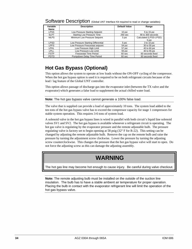
Software Description (Global UNT Interface Kit required to read or change variables)
VariableName
Description Default Value Range
LPSS Low Pressure Starting Setpoint 10 psi 5 to 15 psiSLPT Starting Low Pressure Time 260 sec 90 to 300 secondsMLPS Minimum Low Pressure Setpoint 5 psi Calculated (LPSS-LPSD)
5 psiLPSD Low Pressure Starting Differential 5 psi 3 to 10 psiLPFS Low Pressure Freezestat setpoint 54 psi 30 to 55 psiLPHL Low Pressure High Limit 57 psi 40 to 60 psiLPLL Low Pressure Low Limit 55 psi 40 to 55 psiFSTP Freezestat Time Period 60 sec 60 seconds fixedPDTD Pumpdown Delay Time Period 60 sec 60 seconds fixed
Hot Gas Bypass (Optional)This option allows the system to operate at low loads without the ON-OFF cycling of the compressor.When the hot gas bypass option is used it is required to be on both refrigerant circuits because of thelead / lag feature of the Global UNT controller.
This option allows passage of discharge gas into the evaporator inlet (between the TX valve and theevaporator) which generates a false load to supplement the actual chilled water load.
Note: The hot gas bypass valve cannot generate a 100% false load.
The valve that is supplied can provide a load of approximately 10 tons. The system load added to theten tons of the hot gas bypass valve has to exceed the compressor capacity for stage 1 compressors forstable system operation. This requires 3-6 tons of system load.
A solenoid valve in the hot gas bypass lines is wired in parallel with both circuit’s liquid line solenoidvalves SV1 and SV2. The hot gas bypass is available whenever a refrigerant circuit is operating. Thehot gas valve is regulating by the evaporator pressure and the remote adjustable bulb. The pressureregulating valve is factory set to begin opening at 58 psig (32° F for R-22). This setting can bechanged by adjusting the remote adjustable bulb. Remove the cap on the remote bulb and raise thepressure by turning the adjustment screw clockwise. Lower the pressure by turning the adjustingscrew counterclockwise. This changes the pressure that the hot gas bypass valve will start to open. Donot force the adjusting screw as this can damage the adjusting assembly.
WARNINGThe hot gas line may become hot enough to cause injury. Be careful during valve checkout.
Note: The remote adjusting bulb must be installed on the outside of the suction lineinsulation. The bulb has to have a stable ambient air temperature for proper operation.Placing the bulb in contact with the evaporator refrigerant line will limit the operation of thehot gas bypass valve.

IOM 686 AGZ 030A through 065A 35
Combination Filter DrierEach refrigerant circuit is furnished with a full flow filter drier or an optional replaceable core typefilter-drier. The core assembly of the replaceable core drier consists of a filter core held tightly in theshell in a manner that allows full flow without bypass.
Pressure drop across the filter drier at full load conditions must not exceed 10 psig. If pressuredrop is more than 10 psig, then replace the filter drier.
CAUTIONPump out refrigerant before removing end flange for replacement of core(s).
A condenser liquid line service valve is provided for isolating the charge in the condenser, but alsoserves as the point from which the liquid line can be pumped out. With the line free of liquid, thefilter-drier core(s) can be easily replaced.
System AdjustmentTo maintain peak performance at full load operation, the system superheat and liquid subcooling mayrequire adjustment. Read the following subsections closely to determine if adjustment is required.
Liquid Sightglass and Moisture IndicatorThe color of the moisture indicator is an indication of the dryness of the system and is extremelyimportant when the system has been serviced. Immediately after the system has been opened forservice, the element may indicate a wet condition. It is recommended that the equipment operate forabout 12 hours to allow the system to reach equilibrium before deciding if the system requires achange of drier cores.
Bubbles in the sightglass to expansion valve at constant full load conditions indicates a shortage ofrefrigerant, a plugged filter-drier, or a restriction in the liquid line. However, it is not unusual to seebubbles in the sightglass during changing load conditions.
Refrigerant ChargingLiquid line subcooling at the liquid shut-off valve should be between 15° and 20°F at full load. If theunit is at steady full load operation and bubbles are visible in the sightglass, then check liquidsubcooling.
Thermostatic Expansion ValveThe expansion valve performs one specific function. It keeps the evaporator supplied with the properamount of refrigerant to satisfy the load conditions.
The sensing bulb of the expansion valve is installed in the closest straight run of suction line from theevaporator. The bulb is held on by clamps around the suction line and is insulated to reduce the effectof surrounding ambient temperatures. In case the bulb must be removed, simply slit the insulation oneach side of the bulb, remove the clamps and then remove the capillary tubing that runs along thesuction line from the valve.
The power element is removable from the valve body without removing the valve from the line.
36 AGZ 030A through 065A IOM 686
Note: The superheat is factory set and adjustment is not needed unless unless operation isoutside the 8° to 12°F range.
CAUTIONBefore adjusting superheat, check unit charge is correct and liquid line sightglass is full withno bubbles.
The suction superheat for the suction leaving the evaporator is set at the factory for 8° to 12°F at fullload. To have full rated unit performance the superheat must be about 8°F at 95°F outdoor ambient.
Crankcase HeatersThe scroll compressors are equipped with externally mounted band heaters located at the oil sumplevel. The function of the heater is to keep the temperature in the crankcase high enough to preventrefrigerant from migrating to the crankcase and condensing in the oil during off-cycle.
Power must be supplied to the heaters 24 hours before starting the compressors.
Water CoolerThe water cooler is of the direct expansion type with removable internally finned tubes. The coppertubes are individually rolled into heavy duty steel tube sheets and sealed by a steel refrigerant head.
The water connection nozzles which enter and leave the shell are on the same side of the unit. Nospecial attention is required for the cooler except that clean, filtered water should be supplied.
Sensors and TransducersSensors and transducers are mounted and connected to the Global UNT controller with sensor cable.The evaporator pressure transducers depress the schrader fittings and can be replaced without pumpingthe unit down. The pressure transducers are connected to the Global UNT controller analog inputswith IDC connectors (Insulation Displacement Connectors). The low pressure transducers have a bluedot. The leaving water sensor is in a thermal well for easy replacement without draining the watersystem. As standard, an outside air sensor is provided on the back of the control box. When otherreset options are selected, the outside air sensor is not provided as only one (1) type of reset isavailable.
Control WiringLow voltage control wiring is installed, labeled and tested by the factory before shipment.
External Voltage InputsThe signal for remote reset option (2 to 10 VDC) or demand limit (0 to 10VDC) is provided by theinstalling contractor. Connect to TB -7 terminals #134 (+) and #135 (-) as indicated by the unit wiringdiagram. A 4 to 20mA signal conditioned by a 500 ohm resistor can provide the 2 to 10 VDC inputfor the remote reset option. Polarity of the external DC signal must match the controller polarity.
Interlock WiringAll interlock wiring to field devices (such as a flow switch or time clock) is provided by the installingcontractor. All interlocking wiring must be connected to the Global UNT 24Vac power supply.External power supplies connected to the Global UNT controller can damage the controller. See unitwiring diagram.

IOM 686 AGZ 030A through 065A 37
Unit Set Points and CalibrationThe control software is installed and tested by the factory before shipping. No periodic calibration ofthe controller is necessary. All control and safety set points must be checked by the installingcontractor and adjusted as necessary before starting the unit.
The “setpoint” control knob adjusts the leaving water setpoint. The “Control Band” knob adjuststhe controller temperature control band. To set, divide the chilled water temperature range by thenumber of unloading steps and add 0.5°F.
Optional SensorsOptional sensor kits, available from the factory, can be installed in the field. The optional sensor kitshave the same characteristics as the leaving water sensor.
Field WiringInterconnecting wiring for the control panel may consist of the following:
• 115 VAC power wiring
• Analog input signals
• Digital input signals
• Digital output signals
• Communications to a personal computer
Power WiringThe installing contractor provides the unit voltage power source, disconnect, fuses and necessarywiring for these circuits. All wiring must conform to the National Electrical Code and applicablelocal building codes. If the evaporator heater power source (120VAC) is supplied from a separateexternal supply, remove wires 540 and 545 as indicated on the unit wiring diagram.
Power SuppliesThere are several internal power supplies used by the controller and related circuitry. The regulated 5VDC power is supplied by RSP1 and provides power to pressure transducers. Do not use this powersupply to operate external devices. A 24 VAC power supply is available for the alarm bell option.Wire according to the unit wiring diagram.
Analog input signalsAll sensors and transducers required for normal chiller operation are installed and wired at the factory.All optional analog input signal wiring is provided by the installing contractor must be twisted,shielded pair (Belden #8760 or equal). The optional demand limit and remote reset signals are 0 to10VDC signals. The controlling range of the remote reset signal is from 2VDC to 10 VDC.
Digital input signalsRemote contacts for all digital inputs into the Global UNT controller must be dry contacts suitable forthe 24 VAC control signals from the control panel. Do not connect 120 VAC power to the digitalinputs or 24VAC from an external power source.
Remote Stop/StartIf remote stop/start control is selected, remove the jumper between terminals #140 and #141 on TB-7and install the input between these terminals. When the remote stop/start switch is open, the controllerwill be in the unoccupied mode.

38 AGZ 030A through 065A IOM 686
Chilled Water Flow SwitchThe chilled water flow switch is connected to field wiring terminals #142 and #143 on TB-7. Whenthe chilled water pump is enabled, the Global UNT controller checks for proof-of-flow through theflow switch digital input.
Digital OutputsThe digital outputs are controlled by the Global UNT controller. The outputs are double pole doublethrow plug-in type relays, with a 24Vac holding coil and 120VAC - 7.0 amp rated contacts. Theserelays are field replaceable. Only one contact is used per relay. The contact that is used can benormally open or normal closed and is dependent on the relay function.
External Alarm Annunciator CircuitryAn audible alarm can be connected to the Alarm Output terminals #19 and #28 of TB-3 of the controlpanel and is highly recommended to make certain the operator is alerted to any alarm condition. Thisoutput can also be used to alert a building automation system by paralleling a 24VAC control relaywith the alarm light. This circuit is a 24Vac 1.8 amp maximum load output. The alarm output will beactivated when an alarm condition occurs. Refer to the unit schematic.
Note: The alarm signal is not active during a power failure and will not provide a “Loss ofPower” alarm.
PC ConnectionThe Global UNT controller can be connected to an IBM or IBM compatible computer for setpointchanges and downloading of different software’s. A Global UNT Interface Kit is available from yourlocal McQuay Sales Representative.
Software IdentificationControl software is factory installed and tested in each panel prior to shipment. The software isidentified by a program code which is printed on the a small label attached to the controller.
Controller Inputs /Outputs
Analog InputsAnalog inputs are used to read the various temperatures and pressures on the chiller as well as anycustomer supplied reset signals. The regulated 5 VDC power supply provides correct operatingvoltage for the pressure transducers. This 5VDC supply cannot be used for other inputs.
Table 13, Analog InputsInput Description Location RangeAI-1 Leaving Chilled Water Temp Leaving Chw nozzle 0 to 120oF(0 - 49oC)AI-2 Circuit #1 Evap Pressure Circuit #1 Suction Line 0 to 150 psi (0 - 1034kPa)AI-3 Optional Reset input TB-7 #134 and #135 0/2 to 10VDC / temp sensorAI-4 Leaving Water Temp Setpoint Dial Control Panel 10 to 600 F ( -12 to 150 C)AI-5 Circuit #2 Evap Pressure Circuit #2 Suction Line 0 to 150 psi (0 - 1034kPa)AI-6 Control Band Setpoint Dial Control Panel 0 to 100 F (-17 to -120 C)

IOM 686 AGZ 030A through 065A 39
Digital Inputs
Note: All Digital Inputs are 24 VAC supplied by transformer T2 in the control panel. Do notuse inputs from another power supply external to the unit. This can cause failure of theGlobal UNT controller.
Table 14, Digital InputsInput Description Location Closed OpenBI-1 Time Clock Field Installed to TB-7 #140 & #141 Run StopBI-2 Auto / Pumpdown and Stop Switch Circuit
#1Control Panel Run Pumpdown
StopBI-3 Auto / Pumpdown and Stop Switch Circuit
#2Control Panel Run Pumpdown
StopBI-4 Chilled Water Flow Switch Field Installed to TB-7 #142 & #143 Run Stop
Relay OutputsAll of the relay outputs are controlled by the Global UNT controller. The relays are double poledouble throw relays with contacts rated for 120VAC - 7.0 amp and a 24 Vac holding coil. Refer to theunit staging schematic.
Table 15, Relay Board OutputsRelay Output
NumberOutput
Description1 Circuit #1 Liquid Line Solenoid Valve2 Circuit #2 Liquid Line Solenoid Valve3 Compressor #3 Contactor M34 Compressor #4 Contactor M45 Spare6 Spare7 Low Pressure Relay Circuit #18 Low Pressure Relay Circuit #2
Reset OptionsThe Global UNT controller is capable of one reset option. The reset option should be selected at thetime of purchase. Outside Air is the standard option and a Zone Terminal is necessary to activate thisoption or any other reset option. Other reset options are available and requires a software download.Field modifications can be accomplished with the Global UNT Interface Kit.
Outside Air ResetWhen selected, a Outdoor Air Temperature (OAT) sensor is connected to TB-7 terminals #134 and#135. Four variables are used to setup the reset ramp that calculates the Actual Leaving WaterSetpoint. These are: Leaving Water Setpoint (AI-4), Reset Band selected with a Zone Terminal,Outdoor Air High High Limit (OAHL), and Outdoor Air Reset Band (OARB).
Figure 18, Outside Air Reset
LW R B
LW S P
O A L L O A H L
O A R B(O A LL = O A H L - O A R B )

40 AGZ 030A through 065A IOM 686
As the OAT increases above the Outdoor Air Low Limit (OALL), the Actual Leaving Water Setpoint isdecreased from its Leaving High Limit (Leaving Water Setpoint plus Leaving Reset Band) to theLeaving Water Setpoint. When OAT reaches the OAHL, the Actual Leaving Water Setpoint equals theLeaving Water Setpoint (AI4). If the OAT sensor is missing or unreliable, no reset occurs and theActual Leaving Water Setpoint equals the Leaving Water Setpoint. If the Leaving Water Sensor (AI1)becomes unreliable, the compressor command is forced to 0%.
Return Water Reset (optional Return Water Sensor is required)When selected, a Return Water Temperature (RWT) sensor is connected to TB-7 terminals #134 and#135. Four variables are used to setup the reset ramp that calculates the Actual Leaving WaterSetpoint. These are: Leaving Water Setpoint (AI-4), Reset Band selected with a Zone Terminal,Return Water High Limit (RWHL), and Return Water Reset Band (RWRB).
Figure 19, Return Water Reset
LW R B
LW S P
R W LL R W H L
R W R B(R W LL= R W H L - R W R B )
As the RWT increases above the Return Water Low Limit (RWLL), the controller decreases the ActualLeaving Water Setpoint from its Leaving High Limit (Leaving Water Setpoint plus Leaving ResetBand) to the Leaving Water Setpoint. When RWT reaches the RWHL, the Actual Leaving WaterSetpoint equals the Leaving Water Setpoint (AI-4). If the RWT sensor is missing or unreliable, noreset occurs and the Actual Leaving Water Setpoint equals the Leaving Water Setpoint. If the LeavingWater Sensor (AI-1) becomes unreliable, the compressor command is forced to 0%.
When Return Water Reset is chosen, a Fail Smart Logic option is also available. This option works asfollows. If the Leaving Water Sensor (AI-1) becomes unreliable, the controller switches from LeavingWater control to Return Water control. Actual Return Water Setpoint equals Leaving Water Setpoint(AI-4) plus an adjustable Leaving Water Setpoint Offset. This value takes into account the temperaturedifferential between Leaving and Return water temperatures, which is typically about 10oF. If both theLeaving and Return water sensors are unreliable, the compressor is forced to 0%.

IOM 686 AGZ 030A through 065A 41
Zone Temperature (optional Zone Temperature Sensor )When selected, a Zone Temperature Sensor is connected to TB-7 terminals #134 and #135. Fourvariables are used to setup the reset ramp that calculates the Actual Leaving Water Setpoint. These are:Leaving Water Dial Setpoint (AI-4), Reset Band SP selected with the Zone Terminal, ZoneTemperature High Limit (ZTHL), and Zone Temperature Reset Band (ZTRB).
Figure 20, Zone Temperature Reset
LW R B
LW S P
Z TL L Z T H L
Z T R B(Z T L L= Z T H L - Z T R B )
As the Zone Temperature increases above the Zone Temperature Low Limit (ZTLL), the controllerdecreases the Actual Leaving Water Setpoint from its Leaving High Limit (Leaving Water Setpoint plusLeaving Reset Band) to the Leaving Water Setpoint. When the Zone Temperature reaches the ZTHL,the Actual Leaving Water Setpoint equals the Leaving Water Setpoint (AI-4). If the Zone Temperaturesensor is missing or unreliable, no reset occurs and the Actual Leaving Water Setpoint equals theLeaving Water Setpoint. If the Leaving Water Sensor (AI-1) becomes unreliable, the compressorcommand is forced to 0%.
The Zone Terminal is required to activate and change the reset values.
Remote Reset (2 to 10VDC input)When selected, a 2 to 10VDC signal is connected to TB-7 terminals #134 and #135. This input can beachieved by using a 4-20mA signal and conditioning it with a 500 ohm resistor. This input resets theleaving water temperature to a higher value based on the reset input signal magnitude. At a 2VDC(4mA) chiller signal input, the controller uses the Setpoint Dial setting. At a 10VDC (20mA) signalinput, the controller adds the reset value to the Dial Setpoint for the controlling temperature.Between 2VDC and 10VDC, a proportional value is added to the Dial Setpoint for the controllingtemperature. The leaving water temperature can be reset upwards an additional 15oF. The ZoneTerminal is required to change the reset values.
Demand Limit (0 to 10VDC input)When selected, a 0 to 10VDC signal is connected to TB-7 terminals #134 and #135. This input limitsthe cooling capacity (0 to 100%). At 0VDC signal input, the controller does not limit compressorstaging. At 10VDC signal input, the chiller would be off. Between 0VDC and 10VDC, aproportional percentage capacity is available.
Additional Global UNT Controller Features
Remote Stop/StartWhen the remote stop/start switch is open, the controller will be in the unoccupied mode. The unitwill be enabled when the remote start / stop switch is closed and will control at the leaving watertemperature setpoint.

42 AGZ 030A through 065A IOM 686
Unoccupied ModeWhen the remote start / stop input is opened, the unoccupied mode is initiated. The chiller willmaintain a higher leaving water temperature setpoint (default 70°F) if the chilled water circulation ismaintained. The unoccupied leaving water setpoint can be changed from the Zone Terminal.
Soft StartSoft loading limits the number of available stages when the unit is started to prevent excessive powerconsumption and possible overshoot of the leaving water temperature set point. Soft loading is ineffect whenever the unit is started from an “off” cycle. When stage up starts, the controller starts acountdown timer to indicate how long the unit has been in the cool stage mode. The number of stagesallowed during soft loading is determined by the Soft Start Capacity. The duration of the soft loadsequence is determined by the Soft Start Timer. If the Soft Start Timer is set to zero, no soft loadingwill take place. The Zone Terminal is required to change the Soft Start values.
Compressor StagingThe AGZ Scroll chiller has two refrigerant circuits and each circuit has two scroll compressors. Whenthe first stage of cooling is required, the #1 refrigerant circuit will start. This circuit will be the first tostart for the next ten Starts. The Global UNT controller will then select the #2 refrigerant circuit tostart first for the next ten starts. This cycle will continue and balance the number of starts between therefrigerant circuits. This is an automatic lead / lag control.
The compressors are always started in a fixed order. Refrigerant circuit #1 has compressor #1 andcompressor #3. Compressor #1 will always start first on refrigerant circuit #1. Refrigerant circuit #2has compressor #2 and compressor #4. Compressor #2 will always start first on refrigerant circuit #2.
There are four stages of cooling capacity on the Global Scroll chiller unit. The first stage ofcooling will be the first compressor of the lead refrigerant circuit. The second stage of cooling will bethe first compressor of the lag refrigerant circuit. Cooling stage three will always be compressor #3and cooling stage four will always be compressor #4.
Stage down is the reverse of the above paragraph.
Pumpdown ControlThe AGZ units have a one time pump down. The pump down is activated when a circuit’s liquid linesolenoid valve is de-energized. After the circuit’s liquid line solenoid valve is de-energized, theoperating compressor(s) on that refrigerant circuit will operate until the low pressure switch opens andstops that compressor(s). The compressor will not cycle on if the evaporator pressure exceeds the lowpressure cut-in value. The compressor will start if the Global UNT controller calls for cooling.
The Pumpdown and Stop switch will open its respective circuit’s digital input to the Global UNTcontroller. This will open the associate circuit’s output and open the circuit’s solenoid valve. If acompressor is operating on that circuit, the compressor will operate until the low pressure switchstops the compressor. If a compressor is not running, the switch does not activate a pumpdown forthat circuit but will not allow the circuit to stage on and operate.
Certain alarm conditions will not permit chiller pumpdown. These alarm conditions are:
• High Condenser Pressure
• Bad Evap Pressure Sensor
• Compressor Motor Protect
• Freezestat Alarm

IOM 686 AGZ 030A through 065A 43
Freezestat ControlOn startup the Global UNT controller will check the evaporator pressure after the SLPT(starting lowpressure time) timer times out. If the evaporator pressure is greater than the LPHL (low pressure highlimit) value, the Global UNT controller will continue to stage up as additional cooling is required. Ifthe evaporator pressure is less than the LPHL, the Global UNT controller will de-energize BO7 orBO8 (depends on circuit starting) which will stop the compressor. This is a Freezestat alarm (alarmwill indicate on the optional Zone Terminal) and will require the resetting by depressing theFREEZESTAT RESET on the control panel. The circuit will not go through a pumpdown.
If the chiller has been operating and the evaporator pressure in either circuit is less than the LPFS(low pressure Freezestat setpoint) the Global UNT controller starts the FSTP (Freezestat time period).If the evaporator pressure is below the LPHL after the FSTP times out, BO7 or BO8 (depends onevaporator circuit with the low pressure) will be de-energized stopping the operating compressor(s)and closing that refrigerant circuit’s liquid line solenoid valve. This is a Freezestat alarm (alarm willindicate on the optional Zone Terminal) and will require the resetting by depressing the FREEZESTATRESET on the control panel. There is a five minute time delay after the freezestat reset switch hasbeen depressed. The circuit will not go through a pumpdown upon alarm.
Starting TimersThe Global UNT controller has a starting timer which delays checking the evaporator pressure for 260seconds. After the timer times out, the evaporator pressure is checked. If the pressure is above theLPHL (low pressure high limit, (default 57psi)) value, the controller stages up on leaving watertemperature requirements. If the evaporator pressure is below the LPHL, then the controller will stopthat circuit and indicate a freezestat alarm on the (optional) Zone Terminal.
Head Pressure ControlThere are two condenser fans per refrigerant circuit. These fans are cycled on and off according to thecircuit’s condenser pressure. Fan #1 of a refrigerant circuit will start when number one compressor ofthat refrigerant circuit has started. This fan will not cycle off until the circuit is stopped. The secondfan on a refrigerant circuit will cycle on and off according to its head pressure controller (PC12 orPC22).
Optional Head Pressure Control (SpeedTrol)The first condenser fan on each circuit can have the SpeedTrol option. The fan rpm’s is varied tomaintain a minimum condenser head pressure for stable operation at low ambient temperatures. Windbaffles may be required in addition to the SpeedTrol option for low ambient operation.
Alarms
Circuit Alarm ConditionsThe “Circuit Alarm Conditions” are those alarms which only affect one circuit and can stop thecompressors of that circuit. These alarms are:
• Compressor Motor Protection
• High Condenser Pressure
• Freezestat Protection
The Alarm Light on the control panel will illuminate if either circuit has a high head pressureoccurrence or a compressor motor protection occurrence. Freeze protection would be indicated on theoptional Zone Terminal. If a circuit is off and the panel alarm light is not on, try depressing theFreezestat reset on the control panel. There is a five minute time delay after depressing the resetbutton.
44 AGZ 030A through 065A IOM 686
The chiller must have the manual reset system alarm conditions cleared before normal operationcan resume. If the alarm which occurred is an auto-clearing alarm, once the condition has corrected,the chiller will resume normal operation provided the anti-cycle timers have cleared and sufficient loadexists.
System Alarm ConditionsThe “System Alarm Conditions” are those alarms which are common to both refrigeration circuits andrequire all compressors to be temporarily shut off or locked out, whichever applies.
System alarm conditions are:
• Loss of Water Flow
• Phase Voltage Monitor PVM (Optional)
• Ground Fault Protection GFP (Optional)
The Alarm Light on the control panel will illuminate if either the PVM or GFP has a faultoccurrence. Loss of water flow is indicated on the optional Zone Terminal.
The chiller must have the manual reset system alarm conditions cleared before normal operationcan resume. If the alarm which occurred is an auto-clearing alarm, once the condition has corrected,the chiller will resume normal operation provided the anti-cycle timers have cleared and sufficient loadexists.
ZONE TERMINAL (optional)The Zone Terminal (ZT) is a hand-held or unit mounted device that monitors and adjusts your McQuayGlobal Scroll Chiller information.
A standard telephone-style jack directly connects the ZT to the McQuay Global UNT controller.
Features• Portability
• Simultaneous monitoring of three different settings or values
• Easy operation with only seven buttons
• Flashing numbers to show which items are ZT adjustable
• Flashing symbols to notify you of alarm conditions
CapabilitiesWith the ZT, you can:
• Quickly identify a chiller alarm and its location
• Monitor and adjust up to 18 different settings

IOM 686 AGZ 030A through 065A 45
Figure 21, Zone Terminal
MONITORADJUSTTIME SCHEDULEPASSWORD
ENTER
Compressor 1Compressor 2Stage 3Stage 4
Solenoid #1
Frzstat#1AlmFrzstat#2AlmMinLowPres#1MinLowPres#2
OccupiedFlow FailureOA LockoutCir#2Lead=OnPmp/Stp #1=0
Lvg Water TempEvap Pres #1Evap Pres #2OA/AI3 Input
LvgWtr RBnd SPContrl Band SPActual Lvg SP
Unoccpd Lvg SPOA Lockout SP
Lvg Low Lim SPSoftSta Capcty
Cir #1 StartsCir #2 Starts
McQuay AGZ/AGR Global ChillerINSERT 10
ON OFF
Display Butto n 1
Mo deSele ctor Pan el
Mo de Sele ctorButton
2
AGZ-AGR
Displa y In dicator Do t O n/Of f Sta tus
3
Operating Mode Indicator
Up/Down Arrow Keys
Do or
D isplay Item ListW arn ing Sig nal
ALARM
OA/AI3 HiLimSPOA/AI3 ResetSP
Display Area 11
Display Area 21
Display Area 31
Alarm Light
Lvg Water SP
% Unit Load
SoftStart Time
Pmp/Stp #2=0
Solenoid #2
Stage 5 Opt.Stage 6 Opt.
OPERATING MODESTwo operating modes are included: Monitor and Adjust.
Monitor ModeAs soon as the ZT is connected, it completes a self-check, and starts up in the Monitor Mode. MonitorMode lets you view up to three of chiller settings/sensed values at a time.
To allow you to monitor your system, a clear plastic Insert (factory made and installed) relates theZT’s output to your McQuay Global UNT controller.
You can simultaneously monitor the chiller in three ways:
• Monitor up to three settings/sensed values. A maximum of six items are accessible in each of thethree displays.
• Read the symbols to the right of the display numbers to learn the on/off status of various inputs,outputs, or modes (| = On status; m = Off status). This provides continuous monitoring of 18different status (on/off).
• Monitor alarm status–a flashing red alarm light and any flashing symbol ( |, m, s) visually notifiesyou when your chiller has an alarm condition.
Adjust ModeIn Adjust Mode, the ZT displays information in each of the three numerical displays. Typically, thedisplays are set up so that the relationship between the values can be viewed simultaneously. Forexample:
Display 1 = Lvg Water Temp
Display 2 = Lvg Water SP
Display 3 = % Unit Load
This operating mode allows you to adjust any flashing setpoints. Setpoints adjusted by the ZT remainin effect until you change them.
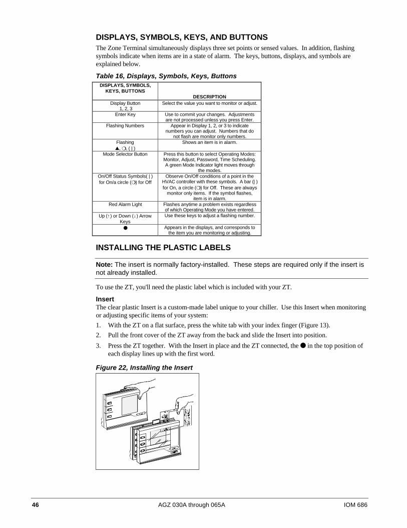
46 AGZ 030A through 065A IOM 686
DISPLAYS, SYMBOLS, KEYS, AND BUTTONSThe Zone Terminal simultaneously displays three set points or sensed values. In addition, flashingsymbols indicate when items are in a state of alarm. The keys, buttons, displays, and symbols areexplained below.
Table 16, Displays, Symbols, Keys, ButtonsDISPLAYS, SYMBOLS,
KEYS, BUTTONSDESCRIPTION
Display Button 1, 2, 3
Select the value you want to monitor or adjust.
Enter Key Use to commit your changes. Adjustmentsare not processed unless you press Enter.
Flashing Numbers Appear in Display 1, 2, or 3 to indicatenumbers you can adjust. Numbers that do
not flash are monitor only numbers.Flashing▲, ❍, ( | )
Shows an item is in alarm.
Mode Selector Button Press this button to select Operating Modes:Monitor, Adjust, Password, Time Scheduling.A green Mode Indicator light moves through
the modes.On/Off Status Symbols( | )for On/a circle (❍) for Off
Observe On/Off conditions of a point in theHVAC controller with these symbols. A bar (| )for On, a circle (❍) for Off. These are always
monitor only items. If the symbol flashes,item is in alarm.
Red Alarm Light Flashes anytime a problem exists regardlessof which Operating Mode you have entered.
Up (↑) or Down (↓) ArrowKeys
Use these keys to adjust a flashing number.
● Appears in the displays, and corresponds tothe item you are monitoring or adjusting.
INSTALLING THE PLASTIC LABELS
Note: The insert is normally factory-installed. These steps are required only if the insert isnot already installed.
To use the ZT, you'll need the plastic label which is included with your ZT.
InsertThe clear plastic Insert is a custom-made label unique to your chiller. Use this Insert when monitoringor adjusting specific items of your system:
1. With the ZT on a flat surface, press the white tab with your index finger (Figure 13).
2. Pull the front cover of the ZT away from the back and slide the Insert into position.
3. Press the ZT together. With the Insert in place and the ZT connected, the ● in the top position ofeach display lines up with the first word.
Figure 22, Installing the Insert

IOM 686 AGZ 030A through 065A 47
CONNECTING THE ZONE TERMINALYou can unit mount the ZT, or use it as a portable tool for convenient access to any chillerinformation.
McQuay Global Scroll Controller ConnectionA standard telephone-style jack connects the ZT to a McQuay Chiller Controller directly.
Figure 23, Connecting ZT to a Global UNT Controller Using 6 to 8 Pin Cable
Connect ZThere.
BINARY INANALOG INPUTS
BINARY OUTPUTS
OFF
1 2 3 4 5 6 7 8
AS-UNT330-1
B INA R Y INANA LOG I NP UTS1 2 3 4 5 6 1 2 3 4
AN AL OG IN PUTSC OMMO N
B IN AR Y C OM
+15V
DC
C OM
P W RI N
2 4 VA C
T OZ ON ESTA T
BINARY OUTPUT
2 4V AC TO LOA DS
1 2 3 4 5 6 7 8
6 PinConnection
8 PinConnection
ALARM STATUSThe ZT indicates an alarm as follows :
• The warning signal (▲) flashes to the right of the Display Indicator dot ( ● ) if the systemoperating values are in alarm.
• The On/Off Status bar ( | ) or circle (❍) flashes when an On/Off status is in alarm.
• The red alarm light to the right of the Mode Selector Panel flashes when any of the above itemsare in alarm.
Alarms cannot be cleared with the ZT. The problem must be corrected by maintenance or repair of theaffected item.
MAKING ZONE TERMINAL ADJUSTMENTS
Adjusting Control Settings1. You can adjust only a flashing number with the ZT. If the number does not flash, that item is a
monitor only item. Adjust Control Settings in Display 1, 2, or 3 as follows:
2. Press the Mode Selector Button until the green Mode Indicator Light moves next to the wordAdjust.
3. Press either Display Button 1, 2, or 3 to locate adjustable items, which are indicated by flashingnumbers.
If you continue pressing the display buttons, the dot ( | ) in each display changes positions andthe corresponding number appears.
4. Press the Up (é) or Down (ê) Arrow key until you reach the number you want to enter. If youhold down the Up (é) or Down (ê) Arrow keys, you can speed through the numbers morequickly.
Press Enter. After you press Enter, the numbers stop flashing for a few seconds. This pausetells you the ZT has processed your adjustment.
5. Press any of the Display Buttons to make other adjustments, and repeat Steps 2 and 3.
48 AGZ 030A through 065A IOM 686
Adjustable PointsThe following McQuay Global Scroll Chiller points are adjustable by the Zone Terminal.
Table 17, Adjustable PointsTEMPLATE VALUES
NAME FACTORY SETPOINT RANGEOA/AI3 HiLim SP 80oF 0 to 100oFOA/AI3 Reset SP -40oF -100 to 100oFLvgWtr Rband SP 0oF 0 to 15oFUnoccpd Lvg SP 70oF 40 to 90oFOA Lockout SP -10oF -20 to 65oFLvg Low Lim SP 20oF 20 to 40oFSoftSta Capcty 50% 0 to 100%SoftStart Time 2 min 0 to 20 minutes
Zone Terminal GlossaryLvg Water Temp - Shows the temperature of the water leaving the evaporator.
Evap Pres #1 - Shows the evaporator pressure for refrigerant circuit #1.
Evap Pres #2 - Shows the evaporator pressure for refrigerant circuit #2.
OA/AI3 Input - Reset input signal (Outdoor Air Temp. is standard), non-adjustable
OA/AI3 HiLimSP - Used in algorithm for Outside Air Reset. Adjusts Outdoor Air High Limit(OAHL)(default is 80° F).
OA/AI3 Reset SP - Used in algorithm for Outside Air Reset. Adjusts Outdoor Air Reset Band(OARB)(default is -40° F; therefore outdoor air reset is 40-80 DegF).
Lvg Water SP - Shows the dial adjustment setpoint. Non-adjustable from ZT.
LvgWtr Rbnd SP - Can be adjusted through the ZT, 0° - 15° F (default is 0° F). Used in algorithmfor Outside Air Reset. (For an example of 10° F reset; 45 DegF Leaving Water Setpoint reset upto 55° F).
Contrl Band SP - Indicates what the Control Band Knob is set at. Non-adjustable from ZT.
Actual Lvg SP - Shows the actual setpoint, including any reset that is occurring.
Unoccpd Lvg SP - Adjustable from 40° F - 90° F (default is 70° F). The setpoint is activated by atimeclock in unoccupied mode.
OA Lockout SP - Adjustable from -20° F to 65° F (default is -10° F). Shuts the unit off when theOutside Air reaches the setpoint. (Differential = 5° F).
% Unit Load - Indicates the % of the unit load.
Lvg Low Lim SP - Adjustable from 20° F - 40° F (default is 20° F). This safety that will shut thechiller off based on the leaving water temperature going below this setpoint.
SoftSta Capcty - Adjusts the ramping of steps from 0% - 100% (default is 50%).
SoftStart Time - Adjustable ramping time from 0 - 20 minutes (default is 2 minutes).
Cir #1 Starts - Counts the number of starts for circuit #1.

IOM 686 AGZ 030A through 065A 49
Cir #2 Starts - Counts the number of starts for circuit #2. Note: If power is lost to thecontroller, this data is lost and will start counting over. When power is applied and kept on, thecontroller will allow 10 starts for circuit #1 as the lead circuit, then will switch to circuit #2 forthe next 10 starts, etc (Automatic Lead/Lag).
Occupied - |= On, 0 = Off
Flow Failure - |= Alarm, 0 = Normal
OA Lockout - Indicates whether your in OA lockout (see OA Lockout SP). No alarm.
Cir#2Lead=On - Indicates which circuit is in the lead e.g., ½= On, 0 = Off indicates that circuit #2 isin the lead.
Pmp/Stp #1=0 - |= Auto, circuit #1 allowed to run if cooling capacity is needed, 0 = Pump downcircut #1 and stop.
Pmp/Stp #2=0 - |= Auto, circuit #2 allowed to run if cooling capacity is needed, 0 = Pump downcircut #2 and stop.
Solenoid #1 - On a call for cooling on circuit 1, the solenoid is energized and opened.
Solenoid #2 - On a call for cooling on circuit 2, the solenoid is energized and opened.
Frzstat#1Alm - If circuit #1 fails on freeze, the alarm light on the ZT will light. To clear the alarm,the Freez-Stat Reset button (located on the Control Panel) must be pushed once to clear.
Frzstat#2Alm - If circuit #2 fails on freeze, the alarm light on the ZT will light. To clear the alarm,the Freez-Stat Reset button (located on the Control Panel) must be pushed once to clear.
MinLowPres#1 - If circuit #1 falls below the Minimum Low Pressure Setpoint (default is 10 psig) -Differential (default is 5 psig) the ZT alarm will light. Once it increases above the Minimum LowPressure Setpoint, the alarm will clear.
MinLowPres#2 - If circuit #2 falls below the Minimum Low Pressure Setpoint (default is 10 psig) -Differential (default is 5 psig) the ZT alarm will light. Once it increases above the Minimum LowPressure Setpoint, the alarm will clear.
Compressor #1 - Compressor 1 is On or Off
Compressor #2 - Compressor 2 is On or Off
Stage 3 to 6 - Indicates how many additional compressor (or unloading) stages are on at the time.
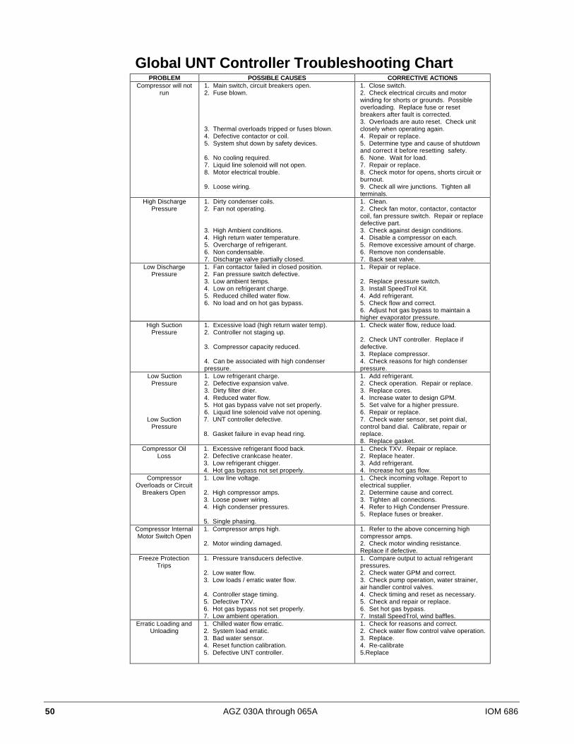
50 AGZ 030A through 065A IOM 686
Global UNT Controller Troubleshooting ChartPROBLEM POSSIBLE CAUSES CORRECTIVE ACTIONS
Compressor will notrun
1. Main switch, circuit breakers open.2. Fuse blown.
3. Thermal overloads tripped or fuses blown.4. Defective contactor or coil.5. System shut down by safety devices.
6. No cooling required.7. Liquid line solenoid will not open.8. Motor electrical trouble.
9. Loose wiring.
1. Close switch.2. Check electrical circuits and motorwinding for shorts or grounds. Possibleoverloading. Replace fuse or resetbreakers after fault is corrected.3. Overloads are auto reset. Check unitclosely when operating again.4. Repair or replace.5. Determine type and cause of shutdownand correct it before resetting safety.6. None. Wait for load.7. Repair or replace.8. Check motor for opens, shorts circuit orburnout.9. Check all wire junctions. Tighten allterminals.
High DischargePressure
1. Dirty condenser coils.2. Fan not operating.
3. High Ambient conditions.4. High return water temperature.5. Overcharge of refrigerant.6. Non condensable.7. Discharge valve partially closed.
1. Clean.2. Check fan motor, contactor, contactorcoil, fan pressure switch. Repair or replacedefective part.3. Check against design conditions.4. Disable a compressor on each.5. Remove excessive amount of charge.6. Remove non condensable.7. Back seat valve.
Low DischargePressure
1. Fan contactor failed in closed position.2. Fan pressure switch defective.3. Low ambient temps.4. Low on refrigerant charge.5. Reduced chilled water flow.6. No load and on hot gas bypass.
1. Repair or replace.
2. Replace pressure switch.3. Install SpeedTrol Kit.4. Add refrigerant.5. Check flow and correct.6. Adjust hot gas bypass to maintain ahigher evaporator pressure.
High SuctionPressure
1. Excessive load (high return water temp).2. Controller not staging up.
3. Compressor capacity reduced.
4. Can be associated with high condenserpressure.
1. Check water flow, reduce load.
2. Check UNT controller. Replace ifdefective.3. Replace compressor.4. Check reasons for high condenserpressure.
Low SuctionPressure
1. Low refrigerant charge.2. Defective expansion valve.3. Dirty filter drier.4. Reduced water flow.5. Hot gas bypass valve not set properly.6. Liquid line solenoid valve not opening.
1. Add refrigerant.2. Check operation. Repair or replace.3. Replace cores.4. Increase water to design GPM.5. Set valve for a higher pressure.6. Repair or replace.
Low SuctionPressure
7. UNT controller defective.
8. Gasket failure in evap head ring.
7. Check water sensor, set point dial,control band dial. Calibrate, repair orreplace.8. Replace gasket.
Compressor OilLoss
1. Excessive refrigerant flood back.2. Defective crankcase heater.3. Low refrigerant chigger.4. Hot gas bypass not set properly.
1. Check TXV. Repair or replace.2. Replace heater.3. Add refrigerant.4. Increase hot gas flow.
CompressorOverloads or Circuit
Breakers Open
1. Low line voltage.
2. High compressor amps.3. Loose power wiring.4. High condenser pressures.
5. Single phasing.
1. Check incoming voltage. Report toelectrical supplier.2. Determine cause and correct.3. Tighten all connections.4. Refer to High Condenser Pressure.5. Replace fuses or breaker.
Compressor InternalMotor Switch Open
1. Compressor amps high.
2. Motor winding damaged.
1. Refer to the above concerning highcompressor amps.2. Check motor winding resistance.Replace if defective.
Freeze ProtectionTrips
1. Pressure transducers defective.
2. Low water flow.3. Low loads / erratic water flow.
4. Controller stage timing.5. Defective TXV.6. Hot gas bypass not set properly.7. Low ambient operation.
1. Compare output to actual refrigerantpressures.2. Check water GPM and correct.3. Check pump operation, water strainer,air handler control valves.4. Check timing and reset as necessary.5. Check and repair or replace.6. Set hot gas bypass.7. Install SpeedTrol, wind baffles.
Erratic Loading andUnloading
1. Chilled water flow erratic.2. System load erratic.3. Bad water sensor.4. Reset function calibration.5. Defective UNT controller.
1. Check for reasons and correct.2. Check water flow control valve operation.3. Replace.4. Re-calibrate5.Replace

IOM 686 AGZ 030A through 065A 51
MicroTech Controller Installation and Operation
All operational descriptions are based on the MicroTech controller software versions AGZ2E01A.Operating characteristics and menu selections may vary with other versions of software. ContactMcQuay Technical Support for software update information.
General DescriptionThe MicroTech control panel contains a model 250-6 microprocessor based controller which providesall control functions. The operator can review and change operating parameters from the interfacekeypad which consists of twelve input keys and a two line by sixteen character display. In addition toproviding all normal operating controls, the controller monitors all safety devices on the unit and willshut the system down and alarm through a set of dedicated alarm contacts. Important operatingconditions at the time of the alarm are retained in the controller’s memory to aid in troubleshootingand unit diagnostics. McQuay MicroTech Monitor software is available for remote adjustment andmonitoring of the chiller.
The system is protected by a simple password scheme which allows access by authorized personnel. Avalid password must be entered into the panel by the operator before any setpoints can be changed.
Optional Sensor Packages• Refrigerant Sensor Package
§ Suction line temperature, circuit #1
§ Suction line temperature, circuit #2
§ Liquid line temperature, circuit #1
§ Liquid line temperature, circuit #2
• Unit amp package
§ Unit amperage - Percent total unit amperage including compressors and condenser fans.Does not include externally powered equipment such as water pumps.
InstallationThe MicroTech controller is shipped factory tested with default values for the type of refrigerant. Allcontrol values must be entered for the specific application of the chiller.
Sensors and transducersSensors and transducers are mounted and connected to the analog / digital input (ADI) board withshielded cable. The evaporator and condenser pressure transducers depress the schrader fittings andcan be replaced without pumping the unit down. The pressure transducers are connected to theMicroTech analog inputs with IDC connectors (Insulation Displacement Connectors). High pressuretransducers have a red dot and low pressure transducers have a blue dot. Water sensors are in thermalwells for easy replacement without draining the water system. Optional refrigerant line temperaturesensors are in a copper sleeve brazed to the appropriated refrigerant line.
Control wiringLow voltage control wiring is installed, labeled and tested by the factory before shipment.
Remote 4-20 milliamp signalsSignals for leaving water reset or demand limit are provided by the installing contractor and connectedto the terminal block as indicated by the unit wiring diagram. See Field Wiring diagram for details.
52 AGZ 030A through 065A IOM 686
Interlock wiringAll interlock wiring to field devices (such as flow switches and pump starters) is provided by theinstalling contractor. See unit wiring diagrams and field wiring diagram.
Unit set points and calibrationThe control software is installed and tested by the factory before shipping. Calibration of thecontroller is not necessary. All control and safety set points must be checked by the installingcontractor and adjusted as necessary before starting the unit. Controllers for McQuay chillers havedefault set points. Refer to the menu items listed below.
• Control mode
• Leaving water temperature
• Head pressure settings
• Compressor staging
• Soft loading
• Holiday dates
• Internal scheduling
• Alarm functions
The default settings are suitable for most installations. The control mode is factory set for “ManualUnit Off”. Check and set the control and safety settings for the application before starting the unit.For more information on menu items, see the menu description section.
Modem kitAn optional modem kit allowing remote monitoring of the chiller from an off-site PC runningMcQuay Monitor software is available from your local McQuay International sales representative.The modem kit comes complete with modem, mounting bracket, wiring harness, and installationinstructions. The modem kit can be field installed or as an option at the factory. Modem wiring isshown on the field wiring diagram.
Optional sensorsOptional sensor kits, available from the factory, can be installed in the field. Thermistors in theoptional sensor kit are the negative coefficient type and have the same characteristics as the enteringand leaving water evaporator sensors.

IOM 686 AGZ 030A through 065A 53
Field WiringInterconnecting wiring for the control panel may consist of the following:
• 115 VAC power wiring
• Chilled water pump relay
• Analog input signals
• Digital input signals
• Digital output signals
• Network communications
• Communications to a personal computer
• Telephone line for remote modem access
Power WiringThe installing contractor provides the unit voltage power source, disconnect, fuses and necessarywiring for these circuits. All wiring must conform to the National Electrical Code and applicablelocal building codes. If the control power source (120VAC) or the evaporator heater power source(120VAC) or both are supplied from a separate external supply, remove wires 540 and 545 asindicated on the field wiring diagram.
Power SuppliesThere are several internal power supplies used by the controller and related circuitry. The regulated5 VDC power is supplied by the controller and provides power to all analog inputs into the ADI board.Do not use this power supply to operate external devices. A 24 VAC power supply is available for thealarm bell option. Wire according to the field wiring diagram.
Analog Input SignalsAll sensors and transducers required for normal chiller operation are installed and wired at the factory,All optional analog signal wiring provided by the installing contractor must be twisted, shielded pair(Belden #8760 or equal). The optional demand limit and leaving water reset signals are 4 to 20milliamp DC signals. The resistive load that conditions the milliamp signal is a 249 ohm resistormounted on the ADI board at the factory.
Digital Input SignalsRemote contacts for all digital inputs into the MicroTech controller must be dry contacts suitable forthe 24 VAC control signals from the control panel. Do not connect 120 VAC power to the digitalinputs.
Remote Stop/StartIf remote stop/start control is selected, remove the jumper between terminals #140 and #141 on TB-7.When the remote stop/start switch is open, the controller will be in the “Off: Remote Sw” mode. Theunit will be enabled when the switch is closed.
Chilled Water Flow SwitchThe chilled water flow switch is connected to field wiring terminals #142 and #143 on TB-7. Whenthe chilled water pump is enabled, the MicroTech controller checks for proof-of-flow through the flowswitch digital input.

54 AGZ 030A through 065A IOM 686
Digital OutputsThe digital output board has normally open solid-state relays with an on-board replaceable 5 amp fuse.The status of all outputs are shown by the individual output red LEDs.
Chilled Water Pump RelayThe optional chilled water pump relay is connected to terminal #10 and #9 on TB-2. When the unit isenabled, the chilled water pump relay is energized. Be sure the relay coil is rated for a maximum loadof 1.8 amps at 120 VAC. There is a 5 amp fuse on the digital output board for this control circuit.
External Alarm Annunciator CircuitryAn audible alarm can be connected to the Alarm Output terminals #19 and #28 of TB-3 of the controlpanel and is highly recommended to make certain the operator is alerted to any alarm condition. Thisoutput can also be used to alert a building automation system or other controls as required. Thiscircuit is a 24Vac 1.8 amp maximum load output but can be used as a dry contact or another voltageby rewiring the circuit. Refer to the unit schematic.
The alarm output can be programmed to activate when an alarm or pre-alarm condition is detected.The alarm signal is de-energized during normal operations. During a fault alarm condition the alarmcircuit will energize and the alarm status light will be on. During a pre-alarm condition the alarmoutput and status light will pulse “on” for one-half second and “off” for four seconds.
Note: The alarm signal is not active during a power failure and will not provide a “Loss ofPower” alarm.
PC ConnectionThe MicroTech controller can be connected to an IBM or IBM compatible computer for local orremote system monitoring. Communication network wiring uses low voltage shielded twisted paircable (Belden 8760 or equal). The network uses the RS232 communications standard with amaximum cable length of 50 Feet. An RS232/485 adapter may be used to allow for cable runs to5000 feet.
Telephone lineIf remote access and monitoring of the unit is chosen, then a voice quality direct dial telephone line isrequired. The line must be a dedicated line and used only for modem access. The phone line must beterminated with a standard RJ-11 modular phone plug
Software IdentificationControl software is factory installed and tested in each panel before shipment. The software isidentified by a program code printed on a small label attached to the controller. The software versionmay also be displayed on the keypad display by viewing the menu items in the Misc. Setup menu. Thesoftware “version” is the last three digits of the software identification code.
Example of typical software identification: AGZ2E01A

IOM 686 AGZ 030A through 065A 55
Controller Inputs /Outputs
Analog InputsAnalog inputs are used to read the various temperatures and pressures on the chiller as well as anycustomer supplied 4-20mA reset signals. The controller’s internal regulated 5 VDC and 12 VDCsupplies provide correct operating voltage for the sensors. See Table 18 for details.
Table 18, Analog InputsInput LED Description Location Range Resolution
0 0 Leaving Chilled Water Temp Leaving Chw nozzle -40 to 263oF 0.1oF1 1 Circuit #1 Evap Pressure Circuit #1 Suction Line 0 to 145 psi 0.1 psi2 2 Circuit #2 Evap Pressure Circuit #2 Suction Line 0 to 145 psi 0.1 psi3 3 Circuit #1 Cond Pressure Compressor Discharge Line- 20 to 450 psi 0.5 psi4 4 Circuit #2 Cond Pressure Compressor Discharge Line- 20 to 450 psi 0.5 psi5 5 Voltage Ratio Signal EnGinn Power Supply 4.1 to 5.1 Vdc --6 6 Chw Water Reset Supplied by others 4 to 20 mA DC --7 7 Demand Limit Signal Supplied by others 4 to 20 mA DC --8 8 Entering Evap Water Temp Entering Chw Nozzle -40 to 263oF 0.1oF9 9 Entering Cond Water Temp Enter Cond Water Nozzle -40 to 263oF 0.1oF10 10 Leaving Cond Water Temp Leaving Cond Water Nozzle -40 to 263oF 0.1oF11 11 % Total Unit Amps Control Cabinet 0 to 4 Vdc --12 12 Circuit #1 Suction Temp Circuit #1 Suction Line -40 to 263oF 0.1oF13 13 Circuit #2 Suction Temp Circuit #2 Suction Line -40 to 263oF 0.1oF14 14 Circuit #1 Liquid Line Temp Circuit #1 Liquid Line -40 to 263oF 0.1oF15 15 Circuit #2 Liquid Line Temp Circuit #2 Liquid Line -40 to 263oF 0.1oF
Digital InputsAll Digital Inputs are 24 VAC. At 7.5 VAC to 24 VAC the digital input contacts are considered closed.Below 7.5 VAC, the contracts are considered open. See Table 19 for details and operatingcharacteristics.
Table 19, Digital InputsInput LED Description Circuit Closed Open
0 0 Mechanical High Pressure Switch Circuit #1 Normal Alarm1 12 2 Motor Protect Switch Compressor Compressor #1 Normal Alarm3 34 4 Motor Protect Switch Compressor Compressor #3 Normal Alarm5 5 System Switch Unit Run Stop6 6 Phase/Voltage Monitor Unit Normal Alarm7 7 Pumpdown Switch Unit Pmp Dn Normal8 8 Mechanical High Pressure Switch Circuit #2 Normal Alarm9 910 10 Motor Protection Switch Compressor #2 Normal Alarm11 1112 12 Motor Protection Switch Compressor #4 Normal Alarm13 13 Chiller Remote Stop Switch Unit Run Stop14 14 Evap Water Flow Switch Unit Run Stop15 15 Pumpdown Switch Circuit #2 Pmp Dn Normal
Relay Board OutputsAll of the MicroTech panel outputs are controlled by solid-state relays which are driven by the model250 controller. The controller activates a solid-state relay by sending a “trigger” signal to the outputboard via the attached ribbon cable. The relay responds to the trigger by lowering it’s resistance whichallows current to flow through it’s “contacts”. When the controller removes the trigger signal, therelay’s resistance becomes very high, causing the current flow to stop. The outputs are individuallyprotected by a 5 amp fuse mounted on the output board adjacent to each relay. Table 20 providesadditional information about each output. Refer to the MicroTech Staging schematic for digitaloutput wiring.

56 AGZ 030A through 065A IOM 686
Table 20, Relay Board OutputsDigital Output
NumberOutput
Description0 Alarm Circuit1 Chilled Water Pump Relay2 Liquid Line Solenoid Circuit #13 Liquid Line Solenoid Circuit #24 Compressor #1 Circuit #15 Compressor #2 Circuit #26 Hot Gas Bypass Circuit #17 Hot Gas Bypass Circuit #28 Compressor #3 Circuit #19 Compressor #4 Circuit #210 Condenser Fan (M11)11 Condenser Fan (M12)12 Spare13 Condenser Fan (M21)14 Condenser Fan (M22)15 Spare
Reset OptionsUser reset options are located in the “Leaving Water Setpoint” menu. The options are:
None“None” is the default value and the leaving evaporator water temperature controls the unit.
ReturnWhen selecting “Return” as the reset mode, the controller resets the leaving water temperature setpoint as required to maintain the selected return water temperature.
4 - 20 mA (remote reset signal)When selecting “4-20mA” as the reset mode, the controller will reset the leaving water temperature toa higher value based on a percentage of the “Maximum Chilled Water Reset”. At 4mA or less, theleaving water temperature is not reset. At 20mA the leaving water temperature is reset to themaximum. Between 4 and 20 mA, the leaving water temperature is reset proportionally to the resetinput signal.
Outside AirWhen selecting “Outside Air” as the reset mode, the controller will reset the leaving water temperatureto a higher value based on the temperature of the outside air (ambient). As the outside air temperaturedecreases, the leaving water temperature is reset up until the maximum reset is obtained. When theoutside air temperature is above the outside air temperature reset setpoint the leaving watertemperature is not reset and is controlled to the leaving water temperature setpoint.
Ice (for lower ice setpoint requirements, consult McQuay Marketing Support)When in “Ice” reset mode, and adequate amount of glycol must be added to the system to protect theevaporator from freezing. McQuay recommends a minimum of 30% solution of ethylene glycol toprotect to 7° F with the minimum leaving water temperature at unit shut down of 21°F. At 21°F shutdown, the saturated refrigerant temperature can approach 10°F.
The leaving water setpoint must be calculated according to the following formula;
LvgEvapSpt = Desired Ice Temperature + 1/2 Control Band + Shut down Delta T
Lvg EvapSpt = 21°F + 1/2 (4)°F + 1.5°F
Lvg Evap Spt = 21°F + 2°F + 1.5°F
Lvg Evap Spt = 24.5°F
IOM 686 AGZ 030A through 065A 57
The remote 4-20mA input must be 4mA or less and the leaving water temperature will be controlled tothe calculated setpoint. When the remote reset input is above 4 mA, the value “MaxChwRst” is addedto the leaving water setpoint. This will be the day operating setpoint. This value cannot be reset whenin the day mode by any other reset options.
The alarm setpoints must be adjusted to allow operation of the chiller at the lower temperatures. Thefollowing values should be adjusted and the example assumes 30% ethylene glycol solution with a21°F shut down temperature:
1. “FrzStat” Set to the saturated suction pressure that corresponds to a temperature several degreeshigher than the freeze point of the water / glycol solution. (10°F = 33psig.)
2. “Frz H2O” Set at least 4° F below the shut down temperature, but not lower than the freezingpoint of the water / glycol solution. (21° F - 4° F = 17° F)
3. “LP cutout” Set 8 to 10 psi below the “Frz State” pressure but never below 20 psig. (33psi - 10psi = 23 psi)
4. “LP Cutin” Set to a saturated suction pressure equal to the shut down temperature plus 1/2 thecontrol band. (21° F + 2° F = 23° F; 23° F = 46psig)
NetworkA network refers to a McQuay MicroTech control panel (CSC or RMS) that can provide controllingfunctions to several McQuay chillers. One function is to control the chiller leaving water temperatureaccording to some control logic in the network control panel. The network control panel will controlthe leaving water setpoint when the “Network” option in the chiller is selected. The network controlpanel will send a signal that reflects 0 to 100% reset of the leaving water set point according to thevalue entered into the “MaxChwRst” of the unit controller.
Soft LoadingSoft loading limits the number of available stages when the unit is started to prevent excessive powerconsumption and possible overshoot of the leaving water temperature set point. Soft loading is ineffect whenever the unit is started from an “off” cycle. On initial start-up, the chiller will turn on thechilled water pump and sample the loop water temperature for a time equal to the Load Delay set point(“LoadDelay”). If cooling is required at the end of the time-delay, a start procedure is initiated. Onentering the “Stage mode” the controller starts a countdown timer to indicate how long the unit hasbeen in the cool stage mode. The number of stages allowed during soft loading is determined by theSoft Load Maximum Stages (“SoftLdMaxStg”). The duration of the soft load sequence is determinedby the Soft Load Timer. If the Soft Load Timer is set to zero, no soft loading will take place. Whenthe soft load option is enabled, any time remaining in the Soft Load Timer will be displayed in themenu Soft Load Set points under item “Time Left”. The following set points may be adjusted inSoftLoadSpts menu:
• Soft Load: This is the amount of time soft loading will be in effect after the controller beginsstaging. If set to zero, soft loading is canceled.
• SoftLdMaxStg: Determines the maximum number of cooling stages which may be energizedwhile soft loading is in effect.
• LoadDelay: The amount of time allowed for the controller to sample the loop water temperaturebefore initiating cooling.
58 AGZ 030A through 065A IOM 686
Manual OperationManual operating modes are available to simplify setup and troubleshooting of the unit. Any of thefollowing manual modes may be selected from the Control Mode Menu.
Note: These manual settings are intended to aid in troubleshooting and should not beconsidered to be normal operating modes. The equipment should not be left unattendedduring manual operation as the automatic staging controls are disabled. The chiller willremain in the manual mode until Automatic operation is selected or a problem alarm occurswhich will change back to the “Automatic mode”.
• ManualOff: Manual unit off.
• Auto1Off2: Automatic Circ#1, Circ#2 off.
• Auto2Off1: Automatic Circ#2, Circ#1 off.
• ManualStaging: Manual Staging, Circ#1 & 2.
Compressor StagingThe AGZ Scroll chiller has two (2) refrigerant circuits and each circuit has two (2) scroll compressors.When in the Automatic mode and stage 1 of cooling is required, the compressor with the lowestnumber of starts will be the first compressor to start. Stage 2 of cooling will start the compressor withthe lowest number of starts in the other refrigerant circuit. Stage 3 of cooling will start the nextcompressor with the lowest number of starts regardless of refrigerant circuit. Stage 4 will start the lastcompressor.
If a compressor is not available for starting due to a safety, the number of cooling stages will bedecreased and always equal to the number of available compressors for operation. At all times thesecond stage of cooling will have a compressor from each refrigerant circuit operating. The exceptionto this is when “LOW AMBIENT” is selected and the outside air temperature is below the low ambientsetting. The staging logic will be modified to start the compressor with the lowest starts and stage 2will start the other compressor on that refrigerant circuit. Both compressors on one refrigerant circuitwill operate at low ambient to improve head pressure control. If additional cooling is required, thenext refrigerant circuit will be started.
On a stage down (4 compressors operating), the compressor with the most run hours will be stopped.The next stage down will be the compressor on the other refrigerant circuit with the most run hours.The next stage down will be the compressor with the most run hours.
Head Pressure ControlThere are two condenser fans per refrigerant circuit. These fans are cycled on and off according to thecircuit’s condenser pressure. Fan #1 of circuit will start when a compressor in the circuit has startedand the condenser pressure exceeds fan on setpoint (230psig R-22). This fan will not cycle off untilthe circuit is stopped. The second fan will cycle on and off to maintain minimum lift pressure. If thecondenser pressure increases rapidly, the second fan will be turned on at 290psig (R-22 setpoint) andremain on until minimum lift pressure regains control.
IOM 686 AGZ 030A through 065A 59
Pumpdown ControlThe AGZ units have a one time pump down. If two compressors are operating on a refrigerant circuitand the chiller is commanded to stop, the lag compressor on that circuit will stop and the leadcompressor will pump the circuit down. Pump down pressure depends on the chiller’s refrigeranttype.
Certain alarm conditions will not permit chiller pumpdown. These alarm conditions are:
• High Condenser Pressure
• Bad Evap Pressure Sensor
• Bad Phase Voltage
• Volts Ratio Protect
• Mechanical High Pressure
• Compressor Motor Protect
Safety SystemsMicroTech continuously performs self diagnostic checks, monitoring all system temperatures,pressures and safeties, and will automatically shut down a refrigerant circuit or the entire unit should afault occur. The cause of the shutdown, time and date of occurrence and conditions at the same timeof alarm will be retained in memory and can be displayed for the operator to review.
The MicroTech controller has several safety systems to safeguard against potential damage of thechiller equipment. There are alarm and pre-alarm conditions. Alarm conditions cause the compressorsto shut off and/or lockout. Pre-alarm conditions cause the unit to stage down in capacity in an attemptto avoid an alarm condition. For alarm conditions, the red “Alarm Status” light on the control panelwill be solid. For all pre-alarm conditions, the light will pulse at the rate of 0.5 seconds on, 4 secondsoff. When an alarm of pre-alarm condition exists, the MicroTech display automatically switches to thealarm menu to alert the user of the condition.
The MicroTech controller alarms can either be of the manual reset type or the auto reset type. Criticalalarm conditions such as High Condenser Pressure, Refrigerant Freeze Protection, and LowEvaporator Pressure which protect against equipment damage are manual reset, which means theylockout compressor operation and must be cleared at the MicroTech keypad before operation canresume. Auto-clearing alarm conditions cause the compressors to shut off on the affected circuit untilthe condition is corrected. When the condition is corrected, the chiller will resume normal operationon that circuit, provided the anti-cycle timers have cleared and sufficient load exists. All pre-alarmconditions are auto-clearing. After the controller stages down the unit on an alarm condition and thepotential alarm condition has been avoided, the alarm will clear y itself and the unit will resumenormal operation. If the alarm condition is not avoided, the alarm will be logged on the MicroTechdisplay, causing lockout of compressors. Thus, the alarm must be manually cleared.
When a McQuay Chiller with a MicroTech controller is used with the McQuay RMS (RemoteMonitoring and Sequencing) Panel, the user must note that alarm nomenclature varies. The RMS hasthree possible categories of alarms: faults, problems, and warnings. The chiller alarm conditioncorresponds with the RMS “fault” condition. Thus, there are system and circuit faults. Chiller pre-alarm conditions correspond to the RMS “problem” designation. Reciprocating chillers do not havewarning alarms.
60 AGZ 030A through 065A IOM 686
Circuit Alarm ConditionsThe “Circuit Alarm Conditions” are those alarms which only affect one circuit and can stop thecompressors of that circuit. These alarms are:
• Compressor Motor Protection
• High Condenser Pressure
• Mechanical High Pressure Switch
• Low Evaporator Pressure
• Refrigerant Freeze Protection
• Bad Pressure Transducer
The chiller must have the manual reset system alarm conditions cleared before normal operation canresume. If the alarm which occurred is an auto-clearing alarm, once the condition has corrected, thechiller will resume normal operation provided the anti-cycle timers have cleared and sufficient loadexists.
System Alarm ConditionsThe “System Alarm Conditions” are those alarms which are common to both refrigeration circuits andrequire all compressors to be temporarily shut off or locked out, whichever applies. The followingalarm conditions are checked continuously during all modes of operation by the controller. If one ofthe following alarm conditions is detected, the mode of the controller will switch to “ Off:Alarm “.The controller disables all compressor operation by turning off all Compressor Enable Outputs.Alarm Output #0 will be turned on to notify the operator of the alarm condition. The red “AlarmStatus” light on the front of the control panel will be solid on the alarm condition and the MicroTechdisplay will show the current alarm condition.
• System alarm conditions are:
• Loss of Water Flow
• Bad Phase /Voltage
• Chilled Water Freeze Protection
• Volts Ratio Protection
• Bad Leaving Water Sensor
The chiller must have the manual reset system alarm conditions cleared before normal operation canresume. If the alarm which occurred is an auto-clearing alarm, once the condition has corrected, thechiller will resume normal operation provided the anti-cycle timers have cleared and sufficient loadexists.
Sequence of Operation
Off ConditionsWith power supplied to the unit, 115VAC power is applied through the control fuse F1 to thecompressor crankcase heaters (HTR1-4), the compressors motor protectors (MP1-4), the evaporatorheater and the primary of the 24v control circuit transformer. The 24V transformer provides power tothe MicroTech controller and related components. With 24V power applied, the controller will checkthe position of the front panel System Switch. If the switch is in the “stop” position the chiller willremain off and the display will indicate the operating mode to be OFF:System Sw. The controller willthen check the PumpDown Switches. If either switch is n the “stop” position, that circuit’s operatingmode will be displayed as OFF:PumpDownSw. If the remote Start/Stop Switch is open, the chillerwill be OFF:Remote Sw. The chiller may also be commanded off via the communications network ifa separate System Master Panel is installed. The display will show OFF:Remote Comm if thisoperating mode is in effect.
IOM 686 AGZ 030A through 065A 61
If an alarm condition exists which prevents normal operation of both refrigerant circuits, the chillerwill be disabled and the display will indicate OFF:Alarm.
Assuming none of the above “OFF” conditions are true, the controller will examine the internal timeclock schedule to determine if the chiller should start. The operating mode will be OFF:TimeClock ifthe time schedule indicates an “OFF” time period.
Start - UpIf none of the “OFF” conditions are true, the controller will initiate a start sequence. The chilled waterpump relay output is energized any time the chiller is enabled and the chiller will remain in the“Waiting For Flow” mode until the field installed flow switch indicates the presence of chilled waterflow. If flow is not proven within 30 seconds, the alarm “Loss of Water Flow” will be activated andthe chiller will continue to wait for proof of chilled water flow. Once flow is established, the alarmwill automatically be cleared and the unit will go into the “Wait For Load” mode.
Once flow is established, the controller will sample the leaving water temperature and compare itagainst the leaving water temperature set point, the control band, the start up delta T and the starttimers. If all values indicate a start (stage 1 cooling), the controller will start the lead circuit byenergizing that circuits liquid line solenoid valve(SV). When the circuit pressure exceeds the LPCutInpressure, the compressor on that circuit with the lowest starts will be started. If additional cooling isrequired (stage 2 cooling), the controller will energize the lag circuit liquid line solenoid valve (SV).When that circuit’s pressure exceeds the LPCutIn pressure, the compressor with the lowest starts willbe started. If additional cooling is required (stage 3 cooling), the next compressor with the loweststarts will be started. Stage 4 cooling will start the last compressor.
When the evaporator water temperature is satisfied, the reverse will occur with the compressor withthe most run hours being stopped in each stage down. If the chiller is operating at minimum capacity(stage 1) and the chilled water temperature falls below the Leaving Evap Water Set Point, control bandand shut down delta T, the controller will stop the last operating compressor. The controller enters the“Waiting For Load” mode and monitor the leaving water temperature.
Low Ambient StartIf the “LOW AMBIENT” option was selected and the out side air temperature is below 50F, the lowambient start logic will replace the normal starting logic. The compressor with the lowest starts on thelead circuit will start when the liquid line solenoid valve is energized. The LPCutIn will be ignoredand the refrigerant freeze protect set point will be ignored for 180 seconds to allow time for therefrigerant pressure to build. After the 180 second time and the evaporator pressure is below thefreeze stat set point, the circuit will shut down and the alarm “LoEvapPressure” will be indicated.
The chilled water freeze alarm set point is enforced during low ambient starts and will shut down thechiller if a water freeze conditions is detected. During the low ambient start period, the evaporatorpressure is monitored and if the evap pressure drops to 2 psi for more than 20 seconds, the chiller willshut off and a “LoEvap Pressure” alarm will be generated. This protects the compressor fromoperating in a vacuum during start-up.
PumpdownAs the system chilled water requirements diminish, the controller will stage down the compressors. Asthe system load continues to drop, the liquid line solenoid valve will be de-energize and the refrigerantcircuit will go through a one time pump down sequence. As the evaporator pressure falls below theLPCutOut set point, the compressor and condenser fan will stop. The evaporator pump output relaywill remain energized and the unit status will indicate “Waiting For Load”.

62 AGZ 030A through 065A IOM 686
Start-Up and Shutdown
Pre-Start CheckoutConfiguration default set points are entered at the factory and all values must be checked and reset foreach installation. Make sure the field wiring for all flow switches, interlocks or jumpers matches theconnections detailed on the field wiring drawing.
Setting of the HEX Address SwitchesThe controller HEX address switches for each unit determine its logical address in a MicroTechnetwork or in an Open Protocol network. If the chiller is not connected to a RS485 communicationsloop, set the address switches as follows: Hi=0; Lo=1.
Network addresses are pre-assigned and will be located in the installation instructions for theparticular network panel.
Control SwitchesBefore applying power to the unit, verify that the Unit System Switch is in the stop position and thateach Circuit Switch is in the Pumpdown and Stop position. It an optional Remote Start / Stop input isinstalled, it should be in the start position.
Ribbon CablesCheck the ribbon cables that connect the keypad, ADI board and output board to the controller. Theyshould be fully seated with the locking tabs engaged.
Powering the MicroTech ControllerThere are three status LEDs located on the model 250 controller which will indicate the controller’soperating condition. When power is first applied to the control panel through the circuit breaker (CB),the red RESET LED will illuminate for approximately 3 seconds. During this time, the controller ischecking the control software and performing internal hardware tests. When these tests are completed,the RESET LED will turn off and the green RUNNING LED will illuminate indicating thecontroller’s circuitry and software are operating correctly. If the RESET LED stays on or theRUNNING LED fails to illuminate, consult the trouble shooting section of the manual.
Any alarms showing should be cleared by pressing the alarm key then the clear key. Watch the LEDson the output board and ADI board to determine the operating status of the controller’s inputs andoutputs while performing the following system checks. Initially all LEDs on the output board will beoff.
Table 21, Initial condition ADI board LEDsDH1 DH2
0 ON 8 ON1 OFF 9 OFF2 ON 10 ON3 OFF 11 OFF4 ON 12 ON5 OFF 13 ON6 ON 14 ** OFF7 ON 15 ON
** Flow switch may be on if not controlled by the unit controller
Move the system switch to the Auto position. LED #5 on the ADI board will turn on. If the timeschedule is in occupied, the chilled water pump relay output board #2 will turn on.
Move both pumpdown switches to the auto position. DH1-7 and DH2-15 will turn off. Thecontroller will then activate one of the refrigerant circuit solenoids depending upon which is the leadcircuit. (output relay #4 circuit #1or output relay #5 circuit #2) When the evaporator pressure rises
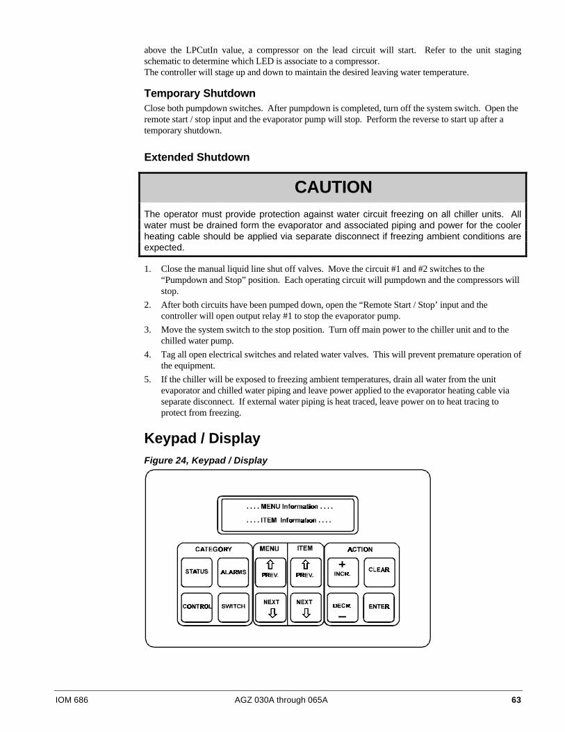
IOM 686 AGZ 030A through 065A 63
above the LPCutIn value, a compressor on the lead circuit will start. Refer to the unit stagingschematic to determine which LED is associate to a compressor.The controller will stage up and down to maintain the desired leaving water temperature.
Temporary ShutdownClose both pumpdown switches. After pumpdown is completed, turn off the system switch. Open theremote start / stop input and the evaporator pump will stop. Perform the reverse to start up after atemporary shutdown.
Extended Shutdown
CAUTIONThe operator must provide protection against water circuit freezing on all chiller units. Allwater must be drained form the evaporator and associated piping and power for the coolerheating cable should be applied via separate disconnect if freezing ambient conditions areexpected.
1. Close the manual liquid line shut off valves. Move the circuit #1 and #2 switches to the“Pumpdown and Stop” position. Each operating circuit will pumpdown and the compressors willstop.
2. After both circuits have been pumped down, open the “Remote Start / Stop’ input and thecontroller will open output relay #1 to stop the evaporator pump.
3. Move the system switch to the stop position. Turn off main power to the chiller unit and to thechilled water pump.
4. Tag all open electrical switches and related water valves. This will prevent premature operation ofthe equipment.
5. If the chiller will be exposed to freezing ambient temperatures, drain all water from the unitevaporator and chilled water piping and leave power applied to the evaporator heating cable viaseparate disconnect. If external water piping is heat traced, leave power on to heat tracing toprotect from freezing.
Keypad / DisplayFigure 24, Keypad / Display
64 AGZ 030A through 065A IOM 686
Menu Structure (general description)The information stored in the MicroTech controller can be accessed through the keypad using a tree-like structure. This tree structure is divided into Categories, Menus and Menu Items. There are threeCategories which make up the tree structure: STATUS, CONTROL, and ALARM. Each category isdivided into Menus and each Menu into Menu Items. The three categories are described below:
• Status category- Menus and menu items in this category provide information on the MicroTechand unit operating conditions. The entries under each menu item in this category provideinformation only and are not changeable through the MicroTech keypad. Menus 1 through 12 areStatus Menus.
• Control category- Menus and menu items in this category provide for the input of all the unitcontrol parameters. These include cooling and heating control, compressor control and condenserfan control parameters as well as time schedules and alarm limits. The entries under these menuitems are changeable through the MicroTech keypad. Menu Items 13 through 23 are ControlMenus.
• Alarm category - Menu and menu items in this category provide information regarding currentand previous alarm conditions. Menus 23 through 27 are Alarm Menus.
Display FormatThe information stored in the MicroTech controller tree structure can be viewed (one menu and menuitem at a time) through a two line by sixteen character LCD display. The current MENU is shown onthe top line and the current MENU item is shown on the bottom line of the display.
MicroTech Menu Structure1. Status category- Where ore than one menu item entry is listed under a menu item, the list includes
all the entries which can appear in the display for the particular item. The entry that shows in thedisplay depends on the operating status of the unit.
2. Control category - Where more than one menu item entry is listed under a menu item, the listincludes all the choices from which the user can select. The selected entry appears in the display.
3. Alarm category-The entries listed include all the possible alarm messages. The display will showthe current and previous alarm conditions for each circuit.
Password InformationWhen changing any menu item entry, the user is prompted to enter the access password. The changewill not be allowed until the correct password is entered. The password for ALR and WHR units isalways the successive pressing of the following “ACTION” group keys:
“ENTER” “ENTER” “ENTER” “ENTER”
Once this has been done, the user can make changes to the menu item entries. After entering the correctpassword, the controller will allow a 5 minute time period during which the operator may make anynecessary setpoint adjustments. Any keypad activity will reset the timer for the full 5 minutes so thepassword only needs to be entered once per session. After 5 minutes of inactivity, the password accesstime will expire providing protection against unauthorized users.

IOM 686 AGZ 030A through 065A 65
Keypad Key FunctionsThe MicroTech keypad consists of twelve pressure sensitive membrane switches (refer to Figure 14).These keys are used to step through, access, and manipulate the information in the MicroTechcontroller tree structure. The keypad keys are divided into four groups with two or four keys in each.These groups of keys and their functions are described below.
Category GroupThe keys in this group provide quick access to strategic menus throughout the menu tree-structure.This reduces the need to step through all the menus, one by one, in order to reach the desired menu.Status-Pressing the “STATUS” key at any time shifts the display to Menu #1 (Unit Status) which is thefirst menu of the Status category.
Control - Pressing the “CONTROL” key at any time shifts the display to Menu #13 (Control Mode)which is the first menu of the Control category. Alarms-Pressing the “ALARMS” key at any timeshifts the display to Menu #24, (Circ 1 Current Alarm) which is the first menu of the Alarms category.Switch - Pressing the “SWITCH” key at any time toggles the display between the current menu(status/control) item and the related menu (control/status) item somewhere else in the tree-structure.For example, if this key is pressed while the current menu item is Menu Item 4A (LeavingEvaporator=), the display shifts to Menu 146 (Leaving Evaporator Set Point=). This provides for easyreview of actual versus set point values. Tables 7, 8 and 9 include a listing of all the currentlysupported switching functions.
Menu GroupThe keys in this group are for stepping from menu to menu in the menu tree-structure. Prev. - Pressing“PREV.” shifts the display to the previous menu. Note: When Menu #I is currently in the display (thefirst menu in the menu tree-structure), pressing “PREV.” causes an “end of menus” message to appearin the display. Pressing “PREV.” again causes the display to wrap around to Menu #27 (the last menuin the tree-structure). Next- Pressing “NEXT” shifts the display to the next menu.
Note: When Menu #27 is currently in the display (the last menu in the menu tree-structure), pressing“NEXT” causes and “end of menus” message to appear in the display. Pressing “NEXT” againcauses the display to wrap around to Menu #1 (the first menu in the menu tree structure).
Item GroupThe keys in this group are for stepping from item to item within a menu. Prev. - Pressing “PREV.”shifts the display to the previous item in a menu. Note: When the first item in a menu is currently inthe display, pressing “PREV.” causing an “end of items” message to appear in the display pressing“PREV.” Again causes the display to wrap around to the last item in the menu.
Next - Pressing “NEXT” shifts the display to the next item in a menu. Note: When the last item in amenu is currently in the display, pressing “NEXT” causes an “end of items” message to appear in thedisplay. Pressing “NEXT” again causes the display to wrap around to the first item in the menu.
Action GroupThe keys in this group are for making changes to unit control parameters or for clearing alarmconditions.
Note: Before a change to a parameter can be made or before an alarm can be cleared, thedisplay prompts the user with an “Enter Password” message. At this point, the passwordmust be entered before the user can continue with the action.
“EN T E R” “EN T E R” “EN T E R” “EN T E R”
Incr - When changing the value of a menu item entry, pressing “INCR. +” shifts the menu item displayline to the next higher or next available selection.
66 AGZ 030A through 065A IOM 686
Decr. -When changing the value of a menu item entry, pressing “DECR. -” shifts the menu item displayline to the next lower value or previous available selection.
Enter- Once a change has been made to a desired value, pressing “ENTER” locks in the new value.
Clear - Pressing “ALARMS” followed by “CLEAR” clears the current alarm. Also, when a change ismade to a menu item pressing “CLEAR” returns the display to the original value as long as “ENTER”has not been pressed.
Note: The cause of an alarm should always be determined and corrected before resetting the alarmthrough the keypad.
Example of Keypad Operation -As an example of using the keypad key functions, considerreprogramming the Leaving Evaporator Set Point from 44°F to 42°F. This consists of changing theMenu Item 148 (Leaving Evaporator Set Point) entry from “44°F to 42°F”. Assume Menu #I (UnitStatus) is currently in the display. The following key sequence is followed.
1. Press the”CATEGORY”group”CONTROL” key one time. This switches the display to Menu#I13 (the first menu in the “CONTROL” category).
2. Press the “MENU” group “NEXT” key once. This shifts the display to Menu Item 14A (Active SetPoint).
3. Press the “ITEM” group “NEXT’ key once. This shifts the display to Menu Item 14B. (LeavingEvaporator setpoint).
4. Press the “ACTION” group ‘DEC -” key one time. This prompts the user to enter the password.
“ENTER” “EN T E R” “EN T E R” “EN T E R”
5. After the “Password Verified” message, press the “ACTION” group “DEC -” key four times. Thischanges the menu item entry to 42°F.
6. Press the “ACTION” group “ENTER” key one time. This stores the new entry into the MicroTechcontroller memory.
7. Pressing the “CATEGORY” group “STATUS” key then shifts the display back to Menu #I.
Menu Descriptions
Status MenusMenus 1 through 12 provide chiller operating information and display of sensor readings. The itemslisted under these status menus are affected by the settings under the associated control menus and arenot directly adjusted via the keypad.
Menu #l: Unit Status -The unit operating status is displayed as item 1 within this menu. The seconditem is the number of seconds remaining in the unit interstage timer. The third item displays the userchosen unit operation of chiller or Templifier (heat pump). Option chosen on Menu 23.
Menu #2: Circuit #l Status-The current operating condition of refrigerant circuit #l is displayedwhenever this menu is selected. There is only one item displayed in this menu.
Menu #3: Circuit #2 Status - The current operating condition of refrigerant circuit #2 is displayedwhenever this menu is selected. There is only one item displayed in this menu.
Menu #4: Water Temperatures -The evaporator leaving water temperature is displayed under item #lunder this menu. Additional items under this menu display the evaporator entering water temperatureas well as the entering and leaving condenser temperatures if these optional sensors have been installedon the unit.
Menu #5: Circuit #l Pressures-The circuit #l evaporator and condenser refrigerant pressure readingsare displayed under this menu. The calculated minimum and maximum condenser pressure values arealso shown.
IOM 686 AGZ 030A through 065A 67
Menu #6: Circuit 62 Pressures -The circuit #2 evaporator and condenser refrigerant pressure readingsare displayed under this menu. The calculated minimum and maximum condenser pressure values arealso shown.
Menu #7: Circuit #l Temperatures-The circuit #I refrigerant temperatures are calculated from theircorresponding pressure sensors and displayed here. If the optional Sensors are not present, the line itemwill flash “Open”.
Menu #8: Circuit #2 Temperatures-The circuit #2 refrigerant temperatures are calculated from theircorresponding pressure sensors and displayed here. If the optional sensors are not present, the line itemwill flash “Open”,
Menu#9: ChillerAmps-Displays the present amp draw of the chiller expressed as a percentage of theunit rated load amps under full load conditions (optional feature).
Menu #10: Compressor Run Hours -The total run hours for each compressor is available under thismenu.
Menu #11: Compressor Starts-The total number of starts for each compressor is available under thismenu.
Menu#12: Air Temperature-Displays the current outdoor air temperature if the optional OAT sensor isinstalled on the air cooled chiller and “Lcl” is selected from Menu 23. Also displayed here is the airtemperature received from a network if the “Rmt” OAT select option from Menu 23 is selected.
Control MenusMenus 13 through 23 are the set point menus. All adjustable control parameters and set points, timeschedules, control options, and alarm thresholds are accessed through these menus.
CAUTIONAny changes to these parameters must be determined and implemented by qualifiedpersonnel with a thorough understanding of how these parameters affect the operation ofthe unit. Negligent or improper adjustment of these controls may result in damage to the unitor personal injury.
Menu #13: Control Mode—One of several automatic and manual operating modes may be selectedfrom within this menu. Typically, the selected control mode will be Automatic which will allow theMicroTech controller to handle all compressor and condenser fan staging. Refrigerant circuit #2 maybe locked off while still allowing circuit #1 to stage automatically by selecting AutoCir#1 -Off#2 asthe operating mode. OffCirc#1 -Auto#2 allows the normal staging of refrigerant circuit #2 but circuit#1 is locked off. Select Manual Staging if manual control is desired. In this operating mode, thecondenser fans are controlled by the MicroTech but the number of stages is determined manually viathe keypad. If manual staging is selected, the second item under this menu indicates the number ofactive cooling stages. Use the INCR or DECR keys to increase or decrease the number of active stages.
Menu#14: Leaving Water Set Points—The leaving wafer set points, control band, maximum pulldown rate and water reset options are adjusted from this menu. The first menu item is The Active SetPoint ("Active Spt"). The current control temperature is displayed here. The Leaving Chilled Water SetPoint ("Lvg Evap") appear towards the top of this menu. These are the set points that will bemaintained for chillers if no reset options are in effect. The Active Control Set Point ("Active Spt")will display the calculated chilled or heated water temperature to be maintained when one of the resetoptions is enabled.
If the 4-20 milliamp reset option is enabled, the controller will reset the leaving chilled watertemperature to a higher value based on a percentage of the Maximum Chilled Water Reset set point("MaxChWRst"). At 4mA or less, no reset will occur. At 20mA, the chilled water set point will bereset to a value equaling the Leaving Evaporator Water Set Point ("Lvg Evap") plus the value stored in
68 AGZ 030A through 065A IOM 686
the "MaxChWRst". Any milliamp value between 4 and 20mA will cause a proportional value of theMaximum Chilled Water Reset to be added to the Leaving Chilled Water Set Point. The external 4-20milliamp control signal and current reset set point will be displayed under "Reset Sig" and "ActiveSpt", respectively, on Menu 14.
By selecting Return as the reset mode, the leaving chilled water temperature will be reset by thecontroller as required to maintain a constant return water temperature. The user must select the"Return" option under "ResetOpt" and select the return set point to be maintained under "ResetSpt".The current leaving chilled water reset set point will be displayed under "Active Spt".
If the chiller is to be used for ice storage, select the "Ice" option in Menu 14 "LvgWater Spt","ResetOpt=". To calculate the leaving chilled water set point, the control band (Menu 14"CntrlBand=") and shut down delta-T (Menu 14 ShutDn D-T=") must first be selected. The equationto determine leaving chilled water temperature is:
For day operation the maximum chilled water reset (Menu 14 "MaxChWRst=") is added to the"Lvg Evap" as calculated above to reach the desired day operating leaving chilled water temperature.
When the Ice option is selected, the resetting of the leaving chilled water set point (during dayoperation) via the 4-20mA input is not a functional option. To retain the option, the set points in Menu14 must be changed by a Building Automation System through our MicroTech Open Protocol MonitorSoftware.
The "Network" reset option allows a signal to be sent reflecting 0-100% reset of the "Lvg Evap"set point (chillers) or "Lvg Cond" set point (THRs) based on the Maximum Chilled Water Reset setpoint. This function acts much like the 4-20 milliamp reset option as described above.
The Maximum Pull Down Rate set point ("MaxPullDn") will prevent overshooting the activewater set point during initial start-up and normal operation. The controller will limit the rate at whichthe chilled water loop temperature is reduced based on an adjustable set point (default of 0.5°F/min).Every minute, the controller checks the leaving water temperature and compares it to the last reading.If the pull rate has been exceeded, the controller will delay additional unit stages.
The Control Band ("CntrlBand") set point defines the temperature range on either side of theactive water set point that must be exceeded in order for a stage up or stage down to occur. The StartUp Delta-T ("StartUpD-T") and Shut Down Delta-T ("ShutDn D-T") define when the unit will startand shut down. The unit will cycle on from a shut down mode once the leaving chilled watertemperature has reached the Leaving Chilled Water Set Point plus half of the Control Band plus theStart Up Delta-T. After the chiller starts, it will stage up and down according to the leaving chilledwater temperature (plus or minus) half the Control Band. Once the load is met and the chiller hasstaged down to stage 1, the unit will shut completely off once the leaving chilled water temperaturehas reached the Leaving Chilled Water Set Point minus half of the Control Band minus the Shut DownDelta-T.
Lvg Evap = Desired Ice Temp + ½ "CntrlBand =" + " ShutDn D - T ="
LvgEvap F= ° + °21 ½ (4) + 1.5 F
Lvg Evap = 21 + 2 + 1.5
Lvg Evap = 24.5

IOM 686 AGZ 030A through 065A 69
Figure 25, Delta-T Setpoints for Chillers
Menu #15: Softload Set Points—The controller can limit the number of available stages when the unitis initially started to prevent excessive power consumption and help control overshoot of the watertemperature set point. The maximum number of stages will equal the Soft Load Maximum Stages forthe time period defined in the softload timer set point. If the softload timer is set to zero, no softloading will take place. Any time remaining in the softload timer will be displayed when the soft loadoption is enabled. During morning start-up, the controller will run the chilled water pump and samplethe loop water temperature for a time equal to the Load Delay set point. If cooling or heating isrequired at the end of this time delay, the first compressor will be started.
Menu #16: Compressor Set Points—This menu is used to set the lead-lag order of the refrigerantcircuits. The lead compressor may be manually set to circuit #1 or circuit #2 or the Automatic modemay be enabled. In Automatic mode, the MicroTech controller will select the refrigerant circuit withthe lowest number starts as the lead. The interstage timer set point sets the delay time between thecurrent cooling stage and the next stage up request. The stage down request time delay is a fixed ratioof the stage up delay.
The minimum Start/Start and Stop/Start timers provide protection against compressor shortcycling. During normal operation the Compressor Interstage Timers provide a time delay betweencooling or heating stages.
Menu #17: Head Pressure Set Points—The set points for head pressure control are adjusted fromwithin this menu. The Minimum Lift Pressure is the minimum differential pressure to be maintainedacross the expansion valve. The dead band defines the pressure differential range within which no fanstaging will occur. If the head pressure moves outside of the deadband, the controller will integrate thepressure error over time. When the Pound/Second exceeds the Stage Up Error or Stage Down Error setpoint, the controller will adjust the fan staging up or down to bring the head pressure back within thedeadband. Refer to the section on head pressure control in this manual for details.
Menu #18: Demand Limit—The Demand Limit set point defines the maximum number of coolingstages allowed by an external demand limit signal. The actual remote demand limit signal level inmilliamps is also displayed here.
In place of demand limit input, a 0 or 5 volts signal from a unit switch open or cool (5 volts - switchclosed) modes.
Menu #19: Time/Date—The MicroTech controller uses an internal calendar and clock to provideautomatic operation for each day of the year. Provision is made for Manual Override to accommodateunscheduled building occupancy. Press the Control key to enter the control area of the menu structurethen press the Next Menu key until the display shows Menu Item #24, Set Date/Time. If the date isincorrect, press the Incr or Decr key and the controller will prompt you for your password. When youhave entered the correct password, the controller will return to the Set Date/ Time display. Press theIncr or Decr keys to scroll the month up or down. Press the Enter key when the display shows thecorrect month. The cursor will advance to the Date position on the display which can be set in the samemanner. After pressing the Enter key to set the Date, the cursor will advance to the Year position on thedisplay. Use the Incr, Decr, and Enter keys to set the correct Year.

70 AGZ 030A through 065A IOM 686
Press the Next Item key. The display will show the current Day, Hour, Minute and Second. If thisinformation needs to be changed, follow the same procedure used to set the Date in the previoussection.
Menu #20: Daily Schedule—This section will help you to set the Daily Start/Stop time for automaticoperation of the chiller. Pressing the Next Menu key and the Next item key will advance the display tothe Daily Time Schedule. This is where the Start and Stop times for each day of the week will be setusing the 24 hour format. Beginning with Sunday, use the Incr and Decr keys to set the desired startand stop time and press the Enter key to store the information in the controller. If the chiller is to beprogrammed to run continuously 24 hours a day, set the stop tie for 1 minute before start time(Stop=23:59; Start=00:00). Press the Next Item key to advance through the remaining week days andHoliday Start/ Stop times.
Menu #21: Holiday Date—Up to 14 holiday dates may be entered. When the MicroTech controller'scurrent date matches a date set in the holiday schedule, the normal daily start/stop times are replaced bythe holiday start/stop ties which were set in the previous section. At the date prompt, use the Incr andDecr keys to set the first holiday month and press Enter to advance to the Day position of the display.Use the lncr, Decr and Enter keys to set the first day of the holiday. Press Next Item to advance toHoliday 1 Duration. If the scheduled holiday spans more than one day, use the lncr and Decr keys to setthe holiday duration and press Enter to store the information in the controller. Use the Next Item key toset additional holiday dates and duration’s for the entire year.
Menu#22: Alarm Set Points—On a call for cooling or heating, the controller will open the liquid linesolenoid valve. When the evaporator pressure rises above the Low Pressure Cutin set point, the firstcompressor will be started. The Low Pressure cut out set point determines the point at which thecompressors will shut off during a pumpdown sequence. The Refrigerant Freeze and Water Freezealarm set points may be adjusted as required. Water and refrigerant freeze alarm time delays may alsobe adjusted for this menu. If the condenser High Pressure set point is exceeded, the controller will shutoff the unit.
Menu #23: Miscellaneous Setup—Several general operating characteristic are defined here. These areset at the factory prior to unit delivery and should not require adjustment. The control software versionnumber is displayed form this menu. Outdoor air temperature is displayed on Menu 12.
Alarm MenusMenus 24 through 27 are used to display any alarm conditions which may be present in the unit. Allalarm messages are accompanied by the date and time when the alarm occurred. Important operatingconditions at the time of the alarm are stored in the controller's memory and may be viewed within thefollowing alarm menus.
Menu #24: Circuit #1 Current Alarm—If refrigerant circuit # 1 is in an alarm condition, theappropriate alarm message will be displayed here. The temperature and pressure readings at the time ofthe alarm will be stored in the controllers memory and may be displayed for analysis from this menu.
Menu #25: Circuit #2 Current Alarm—If refrigerant circuit #2 is in an alarm condition, theappropriate alarm message will be displayed here. The temperature and pressure readings at the timeof the alarm will be stored in the controllers memory and may be displayed for analysis from thismenu.
Menu #26: Circuit #1 Previous Alarm—The alarm type for the last recorded circuit #1 alarm may bedisplayed from this menu. The time and date at which the previous alarm occurred are also displayedhere. This information will be replaced when a current alarm condition is cleared.
Menu #27: Circuit #2 Previous Alarm—The alarm type for the last recorded circuit #2 alarm may bedisplayed from this menu. The time and date at which the previous alarm occurred are also displayedhere. This information will be replaced when a current alarm condition is cleared.
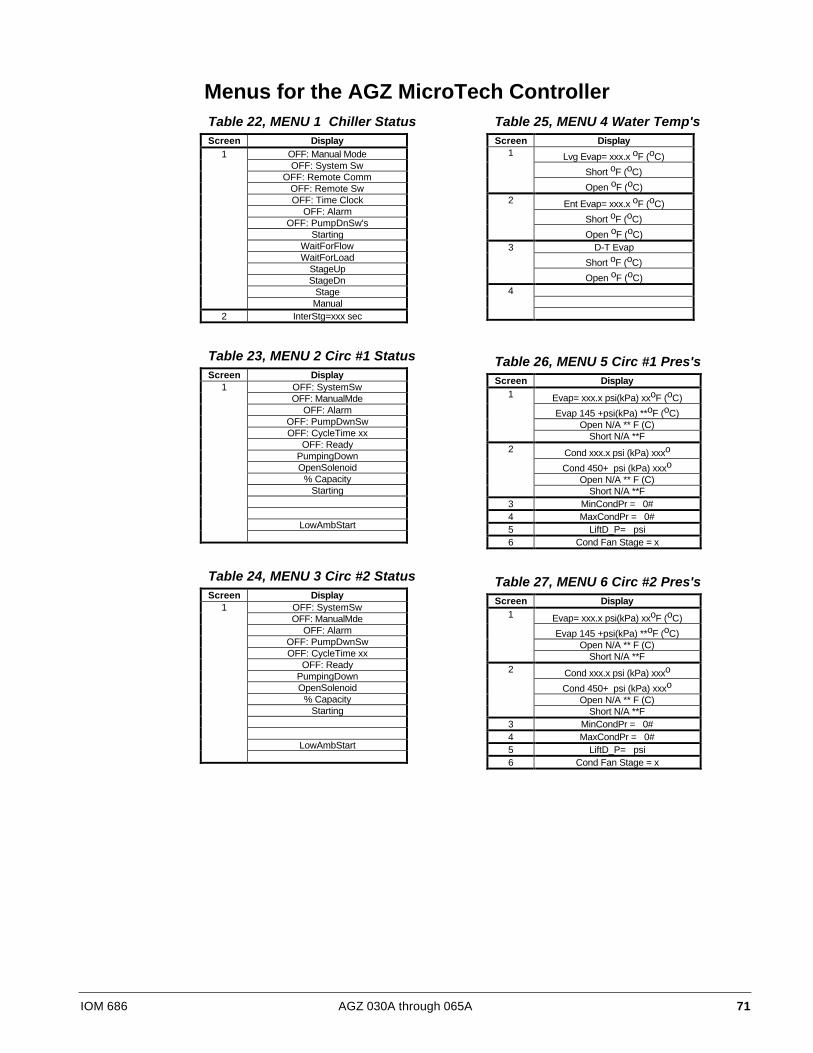
IOM 686 AGZ 030A through 065A 71
Table 22, MENU 1 Chiller StatusScreen Display
1 OFF: Manual ModeOFF: System Sw
OFF: Remote CommOFF: Remote SwOFF: Time Clock
OFF: AlarmOFF: PumpDnSw's
StartingWaitForFlowWaitForLoad
StageUpStageDn
StageManual
2 InterStg=xxx sec
Table 23, MENU 2 Circ #1 StatusScreen Display
1 OFF: SystemSwOFF: ManualMde
OFF: AlarmOFF: PumpDwnSwOFF: CycleTime xx
OFF: ReadyPumpingDownOpenSolenoid
% CapacityStarting
LowAmbStart
Table 24, MENU 3 Circ #2 StatusScreen Display
1 OFF: SystemSwOFF: ManualMde
OFF: AlarmOFF: PumpDwnSwOFF: CycleTime xx
OFF: ReadyPumpingDownOpenSolenoid
% CapacityStarting
LowAmbStart
Table 25, MENU 4 Water Temp'sScreen Display
1 Lvg Evap= xxx.x oF (oC)
Short oF (oC)
Open oF (oC)2 Ent Evap= xxx.x oF (oC)
Short oF (oC)
Open oF (oC)3 D-T Evap
Short oF (oC)
Open oF (oC)4
Table 26, MENU 5 Circ #1 Pres'sScreen Display
1 Evap= xxx.x psi(kPa) xxoF (oC)
Evap 145 +psi(kPa) **oF (oC)Open N/A ** F (C)
Short N/A **F2 Cond xxx.x psi (kPa) xxxo
Cond 450+ psi (kPa) xxxo
Open N/A ** F (C)Short N/A **F
3 MinCondPr = 0#4 MaxCondPr = 0#5 LiftD_P= psi6 Cond Fan Stage = x
Table 27, MENU 6 Circ #2 Pres'sScreen Display
1 Evap= xxx.x psi(kPa) xxoF (oC)
Evap 145 +psi(kPa) **oF (oC)Open N/A ** F (C)
Short N/A **F2 Cond xxx.x psi (kPa) xxxo
Cond 450+ psi (kPa) xxxo
Open N/A ** F (C)Short N/A **F
3 MinCondPr = 0#4 MaxCondPr = 0#5 LiftD_P= psi6 Cond Fan Stage = x
Menus for the AGZ MicroTech Controller
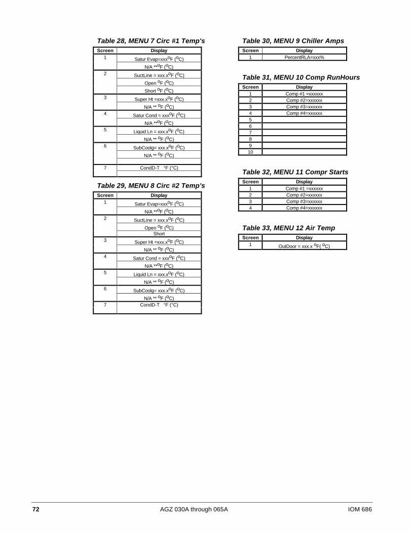
72 AGZ 030A through 065A IOM 686
Table 28, MENU 7 Circ #1 Temp'sScreen Display
1 Satur Evap=xxxoF (oC)
N/A **oF (oC)2 SuctLine = xxx.xoF (oC)
Open oF (oC)
Short oF (oC)3 Super Ht =xxx.xoF (oC)
N/A ** oF (oC)4 Satur Cond = xxxoF (oC)
N/A **oF (oC)5 Liquid Ln = xxx.xoF (oC)
N/A ** oF (oC)6 SubCoolg= xxx.xoF (oC)
N/A ** oF (oC)
7 CondD-T °F (°C)
Table 29, MENU 8 Circ #2 Temp'sScreen Display
1 Satur Evap=xxxoF (oC)
N/A **oF (oC)2 SuctLine = xxx.xoF (oC)
Open oF (oC)Short
3 Super Ht =xxx.xoF (oC)
N/A ** oF (oC)4 Satur Cond = xxxoF (oC)
N/A **oF (oC)5 Liquid Ln = xxx.xoF (oC)
N/A ** oF (oC)6 SubCoolg= xxx.xoF (oC)
N/A ** oF (oC)7 CondD-T °F (°C)
Table 30, MENU 9 Chiller AmpsScreen Display
1 PercentRLA=xxx%
Table 31, MENU 10 Comp RunHoursScreen Display
1 Comp #1 =xxxxxx2 Comp #2=xxxxxx3 Comp #3=xxxxxx4 Comp #4=xxxxxx5678910
Table 32, MENU 11 Compr StartsScreen Display
1 Comp #1 =xxxxxx2 Comp #2=xxxxxx3 Comp #3=xxxxxx4 Comp #4=xxxxxx
Table 33, MENU 12 Air TempScreen Display
1 OutDoor = xxx.x oF( oC)

IOM 686 AGZ 030A through 065A 73
Table 34, MENU 13 Control ModeScreen Display Factory Setpoint Range
1 Manual Unit Off Manual Unit OffAutomatic
Manual Staging
2 Manual Stage=xx 0 1 - 8
Table 35, MENU 14 Lvg Evap SptsValues for R-22 refrigerant, ( ) indicates Centigrade valuesScreen Display Factory Setpoint Range
1 Actv Spt=xxx.x oF (oC) Not Changeable
2 Lvg Evap=xxx.x oF (oC) 44 (6.7) 10 - 80 (-12.2 - 26.7)
3 CntrlBand x.x oF (oC) 3.0 (1.6) 1.0 - 5.0 (0.5 - 2.7)
4 StartUpD-T= x.x oF (oC) 3.0 (1.6) 1.0 - 5.0 (0.5 - 2.7)
5 ShutDn D-T= x.x oF (oC) 1.5 (0.8) 0.0 - 3.0 (0.0 - 1.6)
6 MaxPullDn= x.x oF (oC) 0.5 (0.2) 0.1 - 1.0 (0.0 - 0.5)
7 ResetOpt=None NoneReturn4-20 MaNetwork
Ice8 ResetSig= xx.xma Not Changeable9 MaxChWRst=xx.x oF (oC) 10.0 (5.5) 0.0 - 45.0 (0.0 - 25.0)
10 ReturnSpt= xx.x oF (oC) 54.0 (12.3) 15.0 - 80.0 (-9.4 - 26.7)
[ ] the minus sign is not displayed with three digit numbers
Table 36, MENU 14 Lvg Evap SptsValues for 134a refrigerant, ( ) indicates Centigrade valuesScreen Display Factory Setpoint Range
1 Actv Spt=xxx.x oF (oC) Not Changeable
2 Lvg Evap=xxx.x oF (oC) 44 (6.7) 10 - 80 (-6.6 - 26.7)
3 CntrlBand x.x oF (oC) 3.0 (1.6) 1.0 - 5.0 (0.5 - 2.7)
4 StartUpD-T= x.x oF (oC) 3.0 (1.6) 1.0 - 5.0 (0.5 - 2.7)
5 ShutDn D-T= x.x oF (oC) 1.5 (0.8) 0.0 - 3.0 (0.0 - 1.6)
6 MaxPullDn= x.x oF (oC) 0.5 (0.2) 0.1 - 1.0 (0.0 - 0.5)
7 ResetOpt=None NoneReturn4-40 MaNetwork
Ice8 ResetSig= xx.xma Not Changeable9 MaxChWRst=xx.x oF (oC) 10.0 (5.5) 0.0 - 45.0 (0.0 - 25.0)
10 ReturnSpt= xx.x oF (oC) 54.0 (12.3) 15.0 - 80.0 (-9.4 - 26.7)
[ ] the minus sign is not displayed with three digit numbers

74 AGZ 030A through 065A IOM 686
Table 37, MENU 15 SoftLoad SptsScreen Display Factory Setpoint Range
1 Time Left= xxmin2 SoftLoad= xx min 20 0 - 2543 SoftLdMaxStg= x 4 1 - 44 LoadDelay= xxsec 15 0 - 254
Table 38, MENU 16 CompressorSptScreen Display Factory Setpoint Range
1 Sequence=Auto Auto 12341432214323413214341241234321
2 StageUp= xxx sec3 StageDn= xxx sec4 MinST-ST=xx min 15 5 - 405 MinSP-ST xx min 5 3 - 30
Comp #1 Disable / EnableComp #2 Disable / EnableComp #3 Disable / EnableComp #4 Disable / Enable
Table 39, MENU 17 Head Pres SptValues for R-22 refrigerant, ( ) indicates Centigrade valuesScreen Display Factory Setpoint Range
12 MinLift 50%=xxx 80 (552) 70 - 100 (483 - 690)3 MinLift100%=xxx 140 (966) 100 - 140 (690 - 966)4 DeadBandMult= x.x 1.0 .8 - 1.35 StageUpErr= xxx 400 (2760) 300 - 990 (2070 - 6830)6 StageDnErr = xxx 100 (690) 50 - 400 (340 - 2760)
Table 40, MENU 17 Head Pres SptValues for 134a refrigerant, ( ) indicates Centigrade valuesScreen Display Factory Setpoint Range
2 MinLift 50%=xxx 56 (386) 50 - 80 (345 - 552)3 MinLift100%=xxx 90 (621) 80 - 122 (552 - 841)4 DeadBandMult= x.x 1.0 .8 - 1.35 StageUpErr= xxx 400 (2760) 300 - 990 (2070 - 6830)6 StageDnErr = xxx 100 (690) 50 - 400 (340 - 2760)
Table 41, MENU 18 Demand LimitsScreen Display Factory Setpoint Range
1 Demand Lim= xstg 3 Not Changeable at this screen2 DemandSg= xx.x ma Actual Value Indicates the Magnitude of the
Demand Limit Signal
Table 42, MENU 19 Time / DateScreen Display Factory Setpoint Range
1 Time= xx:xx:xx Actual Time2 Mon xx/xx/xx Actual Day and Date

IOM 686 AGZ 030A through 065A 75
Table 43, MENU 20 ScheduleScreen Display Factory Setpoint Range
1 Override= xx.xx hr 0.00 Hr 00:00 - 63.502 NMPSchedule= N/A N/A3 Sun 00:00-23:59 00:00 - 23:59 00:00 - 23:594 Mon 00:00-23:59 00:00 - 23:59 00:00 - 23:595 Tue 00:00-23:59 00:00 - 23:59 00:00 - 23:596 Wed 00:00-23:59 00:00 - 23:59 00:00 - 23:597 Thu 00:00-23:59 00:00 - 23:59 00:00 - 23:598 Fri 00:00-23:59 00:00 - 23:59 00:00 - 23:599 Sat 00:00-23:59 00:00 - 23:59 00:00 - 23:5910 Hol 00:00-23:59 00:00 - 23:59 00:00 - 23:59
Table 44, MENU 21 Holiday DateScreen Display Factory Setpoint Range
1 #1 Date = N/A 0 N/A 0 Jan - Dec 1 - 312 #1 Dur = 0 Day(s) 0 0 - 313 #2 Date = N/A 0 N/A 0 Jan - Dec 1 - 314 #2 Dur = 0 Day(s) 0 0 - 315 #3 Date = N/A 0 N/A 0 Jan - Dec 1 - 316 #3 Dur = 0 Day(s) 0 0 - 317 #4 Date = N/A 0 N/A 0 Jan - Dec 1 - 318 #4 Dur = 0 Day(s) 0 0 - 319 #5 Date = N/A 0 N/A 0 Jan - Dec 1 - 3110 #5 Dur = 0 Day(s) 0 0 - 3111 #6 Date = N/A 0 N/A 0 Jan - Dec 1 - 3112 #6 Dur = 0 Day(s) 0 0 - 3113 #7 Date = N/A 0 N/A 0 Jan - Dec 1 - 3114 #7 Dur = 0 Day(s) 0 0 - 3115 #8 Date = N/A 0 N/A 0 Jan - Dec 1 - 3116 #8 Dur = 0 Day(s) 0 0 - 3117 #9 Date = N/A 0 N/A 0 Jan - Dec 1 - 3118 #9 Dur = 0 Day(s) 0 0 - 3119 #10 Date = N/A 0 N/A 0 Jan - Dec 1 - 3120 #10 Dur = 0 Day(s) 0 0 - 3121 #11 Date = N/A 0 N/A 0 Jan - Dec 1 - 3122 #11 Dur = 0 Day(s) 0 0 - 3123 #12 Date = N/A 0 N/A 0 Jan - Dec 1 - 3124 #12 Dur = 0 Day(s) 0 0 - 3125 #13 Date = N/A 0 N/A 0 Jan - Dec 1 - 3126 #13 Dur = 0 Day(s) 0 0 - 3127 #14 Date = N/A 0 N/A 0 Jan - Dec 1 - 3128 #14 Dur = 0 Day(s) 0 0 - 31
Table 45, MENU 22 Alarm SptsValues for R-22 refrigerant, ( ) indicates Centigrade valuesScreen Display Factory Setpoint Range
1 StpPumpDn =xxpsi (kPa) 34 (234) 2 - 54 (13 - 372)2 FullPumpDown= No No No - yes3 FreezStat= xxpsi (kPa) 54 (372) 20 - 60 (138 - 414)4 FreezH2O= xx.x oF (oC) 36.0 (2.3) 0.0 - 40.0 (-17.5 - 4.5)
5 FreezeTim= xxx sec6 Hi Press = xxxpsi (kPa) 380 (2622) 280 - 426 (1932 - 2939)
Table 46, MENU 22 Alarm SptsValues for 134a refrigerant, ( ) indicates Centigrade valuesScreen Display Factory Setpoint Range
1 StpPumpDn =xxpsi (kPa) 14 (96) 2 - 22 (13 - 151)2 FullPumpDown= No No No - yes3 FreezStat= xxpsi (kPa) 26 (179) 4 - 26 (27 - 179)4 FreezH2O= xx.x oF (oC) 36.0 (2.3) 0.0 - 40.0 (-17.5 - 4.5)
5 FreezeTim= xxx sec6 Hi Press = xxxpsi (kPa) 380 (2622) 280 - 426 (1932 - 2939)

76 AGZ 030A through 065A IOM 686
Table 47, MENU 23 Misc SetupScreen Display Factory Setpoint Range
1 Unit Type= Air Cooled
2 Units = English English English - Metric
4 SpeedTrol = No No No - Yes5 Power = 60 hz 60 60 - 506 Port A Baud=xxxx 9600 9600 - 2400 - 12007 Pre-Alarm=Blink Blink Blink - Open - Closed
OpenClosed
8 Alarm=Closed Closed Closed - Blink(N/O) - Blink(N/C)Blink(N/O)Blink(N/C)
9 OAT Select=None None None - Lcl - RmtLclRmt
10 LvgEvpAdj= 0.0 oF(oC) -0.8 - 0.8 (-0.4 - 0.5)
11 EntEvpAdj= 0.0 oF(oC) -0.8 - 0.8 (-0.4 - 0.5)
12 #1EvpAdj= 0.0psi (kPa) (-13.8 - 13.8)13 #2EvpAdj= 0.0psi (kPa) (-13.8 - 13.8)14 #1CndAdj= 0.0psi (kPa) (-13.8 - 13.8)15 #2CndAdj= 0.0psi (kPa) (-13.8 - 13.8)16 Refrigerant= R22 Not Changeable17 Not Changeable
Table 48, MENU 24 #1 Curr AlarmScreen Display
1 Current Alarm2 @ 0:00 0/00/003 Evap = x.x psi (kPa)4 Cond = x.x psi (kPa)5 SuctLine=xxx.x oF(oC) 6 LiquisLn=xxx.x oF(oC) 7 Evap Lvg=xxx.x oF(oC) 8 OAT=xx.xxoF(oC)9 Capacity= xxx%
10 Fan Stage = x
Table 49, MENU 25 #2 Curr AlarmScreen Display
1 Current Alarm2 @ 0:00 0/00/003 Evap = x.x psi (kPa)4 Cond = x.x psi (kPa)5 SuctLine=xxx.x oF(oC) 6 LiquisLn=xxx.x oF(oC) 7 Evap Lvg=xxx.x oF(oC) 8 OAT=xx.xxoF(oC)9 Capacity= xxx%
10 Fan Stage = x
Table 50, MENU 26 #1 PrevAlarmScreen Display
1 1 Current Alarm2 1 x:xx x/xx/xx3 2 Current Alarm4 2 x:xx x/xx/xx5 3 Current Alarm 6 3 x:xx x/xx/xx 7 4 Current Alarm 8 4 x:xx x/xx/xx9 5 Current Alarm
10 5 x:xx x/xx/xx
Table 51, MENU 27 #2 PrevAlarmScreen Display
1 1 Current Alarm2 1 x:xx x/xx/xx3 2 Current Alarm4 2 x:xx x/xx/xx5 3 Current Alarm 6 3 x:xx x/xx/xx 7 4 Current Alarm 8 4 x:xx x/xx/xx9 5 Current Alarm
10 5 x:xx x/xx/xx

IOM 686 AGZ 030A through 065A 77
Trouble Analysis for the AGZ MicroTech Controller
Microprocessor Control BoardThe Microprocessor Control Board (MCB) is shown in Figure 26. It contains a microprocessor that ispreprogrammed with the software required to monitor and control the chiller. The various MCBconnections and components are described below.
Figure 26, Microprocessor Control Board (MCB)
RUNNINGRESET
ACTIVE OUTPUT 0
CPUSTATUS
POWER FUSES[BUSSMAN GDC-T2A]
PO
WE
R IN
[18-
24 V
CT
]A
C A
C G
ND
GN
D
AUX/OUT
DIGITAL OUTPUTSA
NA
LO
G IN
PU
TS
DIG
ITA
L IN
PU
TS
HI
ADDRESS
LO
KE
YP
AD
/LC
D D
ISP
LA
Y
COMMUNICATIONSPORT A PORT B
[FUSE: BUSSMAN MCR-1/4]
FUSE 12
34
Hex switches
Microprocessor status LED's
EXPANSION BUS
Digital Inputs ConnectionThe MCB receives digital inputs from the Analog Digital Input (ADI) board through the Digital Inputsconnector via a plug-in ribbon cable. These inputs are conditioned by the ADI board.
Analog Inputs ConnectionThe MCB receives conditioned analog inputs from the ADI board through the Analog Inputs connectorvia a plug-in ribbon cable. These inputs are conditioned by the ADI board. After having beenconditioned, all analog inputs enter the MCB through the Analog Inputs port as 0–5 Vdc signals.
Digital Outputs ConnectionAfter processing all input conditions, the MCB sends the appropriate output signals to output devicesthrough the Digital Outputs port via a plug-in ribbon cable.
Power In ConnectorThe MCB receives 18 Vac, center-tapped power from transformer T4 through the Power In connector.This power drives all logic and communications circuitry
Power FusesTwo identical 2-amp fuses are located to the right of the Power In connector. These fuses are in theMCB power supply circuit.
Microprocessor Status LEDsThe green, red, and amber LEDs on the MCB provide information about the operating status of themicroprocessor. The amber LED also indicates the existence of alarm conditions.
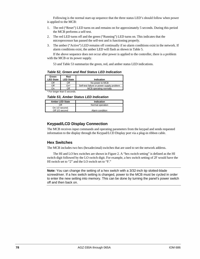
78 AGZ 030A through 065A IOM 686
Following is the normal start-up sequence that the three status LED’s should follow when poweris applied to the MCB:
1. The red (“Reset”) LED turns on and remains on for approximately 5 seconds. During this periodthe MCB performs a self-test.
2. The red LED turns off and the green (“Running”) LED turns on. This indicates that themicroprocessor has passed the self-test and is functioning properly.
3. The amber (“Active”) LED remains off continually if no alarm conditions exist in the network. Ifalarm conditions exist, the amber LED will flash as shown in Table 5.
If the above sequence does not occur after power is applied to the controller, there is a problemwith the MCB or its power supply.
53 and Table 53 summarize the green, red, and amber status LED indications.
Table 52, Green and Red Status LED IndicationGreen
LED StateRed
LED State IndicationOff Off No power to MCBOff On* Self-test failure or power supply problemOn Off MCB operating normally
* For longer than 5 seconds.
Table 53, Amber Status LED IndicationAmber LED State Indication
Off Normal operationOn 1/2 second;Off 1/2 second Alarm condition
Keypad/LCD Display ConnectionThe MCB receives input commands and operating parameters from the keypad and sends requestedinformation to the display through the Keypad/LCD Display port via a plug-in ribbon cable.
Hex SwitchesThe MCB includes two hex (hexadecimal) switches that are used to set the network address.
The HI and LO hex switches are shown in Figure 2. A “hex switch setting” is defined as the HIswitch digit followed by the LO switch digit. For example, a hex switch setting of 2F would have theHI switch set to “2” and the LO switch set to “F.”
Note: You can change the setting of a hex switch with a 3/32-inch tip slotted-bladescrewdriver. If a hex switch setting is changed, power to the MCB must be cycled in orderto enter the new setting into memory. This can be done by turning the panel’s power switchoff and then back on.

IOM 686 AGZ 030A through 065A 79
Figure 27, Hex Switches
1 2
3
0
45
6
789A
BC
D
EF 1 2
3
0
45
6
789A
BC
D
EF
HI (left) hex switch LO (right) hex switch
* Hex switch setting 01 shown
Communication PortsThe MCB has two communication ports: port A and port B. Each port has six terminals and is set upfor both the RS-232C and RS-485 data transmission interface standards. The male and femaleconnectors for these ports are manufactured by AMP. Therefore, they are referred to as “AMP plugs”or “AMP connectors” throughout this manual. Socket fuses located next to the ports protect thecommunications drivers from voltage in excess of ±12 Vdc. Following are brief descriptions of eachport’s function.
Port A: Port A is for communications with an IBM compatible PC using the RS-232C interfacestandard. The PC can be directly connected, over a limited distance, with a twisted, shielded pair cable,or it can be remotely connected via phone lines with a modem. Port A can also be used to connect alicensed building automation system to the MicroTech network via Open Protocol. The defaultcommunications rate is 9600 baud.
Port B: Port B is for MicroTech network communications using the RS-485 interface standard. Atwisted, shielded pair cable should be connected to port B via terminals B+, B–, and GND on terminalblock T11. The communications rate is 9600 baud.
Output BoardThe Output Board (OB) accepts up to 16 digital outputs from the MCB. Each output has fusedsockets and can be used to switch AC or DC power by selecting a particular relay output module.Screw terminals allow for field wiring connections to the output device. Each output has an onboardLED that illuminates when an output socket that contains a relay is activated by the MCB. Followingare the Output Board’s power ratings:
• 120V ~ 50/60 Hz
• 250V ~ 50/60 Hz
PowerAbove each edge card connector are field wiring terminals for 5 Vdc (regulated) and 24 Vac (groundreferenced). These terminals can be used to power peripheral devices. The 5 Vdc is also used to powerthe LEDs in the Output Board.

80 AGZ 030A through 065A IOM 686
Test Procedures
Status LED DiagnosticsThe MCB status LED indications can aid in controller diagnostics. If the status LEDs do not operatenormally there is a problem with the MCB. Following are troubleshooting procedures for the varioussymptoms.
Red LED Remains OnIf the red LED remains on after the 5-second self-test period, it is likely that the MCB is defective.However, this can also occur in some instances if there is a power supply problem. Refer to“Troubleshooting Power Problems” below.
Red and Green LEDs OffIf the red and green LEDs do not turn on after power is applied to the controller, there is likely adefective component or a problem in the controller’s power distribution circuits. Refer to“Troubleshooting Power Problems” below.
Troubleshooting Power ProblemsThe MCB receives 18 Vac, center-tapped power from transformer T4. It then distributes both 5 Vdcand 13 Vdc power to various MicroTech components. A problem that exists in any of thesecomponents can affect the MCB and thus the entire control system. Power problems can be caused byan external short, which can blow a fuse, or a defective component, which can either blow a fuse orcreate an excessive load on the power supply. An excessive load can lower the power supply voltagesto unacceptable levels. Use the following procedure to isolate the problem. Note that this proceduremay require two or three spare MCB fuses . Refer to the panel wiring diagram.
1. Verify that circuit breaker CB1 is closed.
2. Remove the MCB Power In connector and check for 9 Vac between the terminals on the plugcorresponding to terminals 2 and 3 on the board. Then check for 9 Vac between the terminals onthe plug corresponding to terminals 1 and 3 on the board. (Readings of 9–12 Vac are acceptable.)If 9 Vac is present between both sets of terminals, go to step 3If 9 Vac is not present between both sets of terminals, check transformers T2 and T3 and allwiring between the 115 Vac source and the Power In plug.
3. Remove power from the controller by opening circuit breaker CB1. Check the MCB powersupply input fuses (F1 and F2) with an ohmmeter. A good fuse will have negligible resistancethrough it (less than 2 ohms).If either or both fuses are blown, replace them. Go to step 4.If the fuses are intact, the MCB is defective.
4. Reconnect the Power In connector and disconnect all other connectors on the MCB. Cycle powerto the controller (close and then open CB1) and check the power fuses.If both fuses are intact, go to step 5.If either fuse blows, the MCB is defective.
5. Reconnect the keypad/display ribbon cable . Cycle power to the controller and check the powerfuses.If both fuses are intact, go to step 6.If either fuse blows, check the keypad/display and the connecting ribbon cable for shorts. Eitherone may be defective.
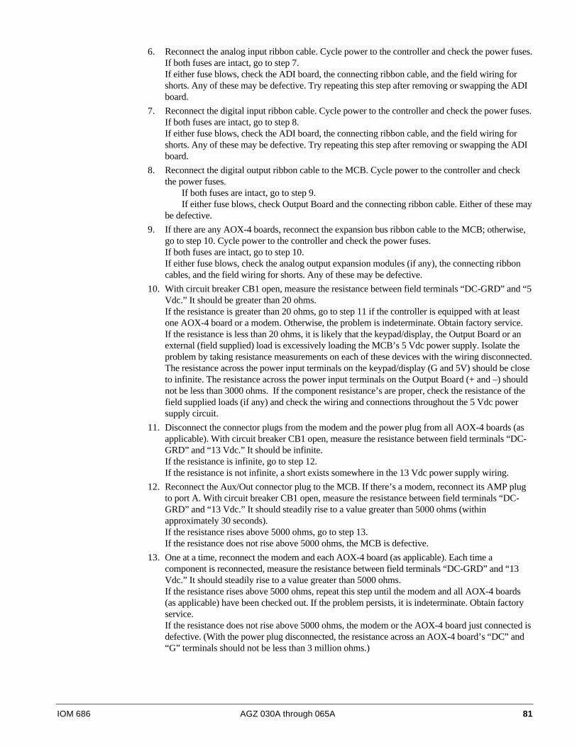
IOM 686 AGZ 030A through 065A 81
6. Reconnect the analog input ribbon cable. Cycle power to the controller and check the power fuses.If both fuses are intact, go to step 7.If either fuse blows, check the ADI board, the connecting ribbon cable, and the field wiring forshorts. Any of these may be defective. Try repeating this step after removing or swapping the ADIboard.
7. Reconnect the digital input ribbon cable. Cycle power to the controller and check the power fuses.If both fuses are intact, go to step 8.If either fuse blows, check the ADI board, the connecting ribbon cable, and the field wiring forshorts. Any of these may be defective. Try repeating this step after removing or swapping the ADIboard.
8. Reconnect the digital output ribbon cable to the MCB. Cycle power to the controller and checkthe power fuses. If both fuses are intact, go to step 9. If either fuse blows, check Output Board and the connecting ribbon cable. Either of these maybe defective.
9. If there are any AOX-4 boards, reconnect the expansion bus ribbon cable to the MCB; otherwise,go to step 10. Cycle power to the controller and check the power fuses.If both fuses are intact, go to step 10.If either fuse blows, check the analog output expansion modules (if any), the connecting ribboncables, and the field wiring for shorts. Any of these may be defective.
10. With circuit breaker CB1 open, measure the resistance between field terminals “DC-GRD” and “5Vdc.” It should be greater than 20 ohms.If the resistance is greater than 20 ohms, go to step 11 if the controller is equipped with at leastone AOX-4 board or a modem. Otherwise, the problem is indeterminate. Obtain factory service.If the resistance is less than 20 ohms, it is likely that the keypad/display, the Output Board or anexternal (field supplied) load is excessively loading the MCB’s 5 Vdc power supply. Isolate theproblem by taking resistance measurements on each of these devices with the wiring disconnected.The resistance across the power input terminals on the keypad/display (G and 5V) should be closeto infinite. The resistance across the power input terminals on the Output Board (+ and –) shouldnot be less than 3000 ohms. If the component resistance’s are proper, check the resistance of thefield supplied loads (if any) and check the wiring and connections throughout the 5 Vdc powersupply circuit.
11. Disconnect the connector plugs from the modem and the power plug from all AOX-4 boards (asapplicable). With circuit breaker CB1 open, measure the resistance between field terminals “DC-GRD” and “13 Vdc.” It should be infinite.If the resistance is infinite, go to step 12.If the resistance is not infinite, a short exists somewhere in the 13 Vdc power supply wiring.
12. Reconnect the Aux/Out connector plug to the MCB. If there’s a modem, reconnect its AMP plugto port A. With circuit breaker CB1 open, measure the resistance between field terminals “DC-GRD” and “13 Vdc.” It should steadily rise to a value greater than 5000 ohms (withinapproximately 30 seconds).If the resistance rises above 5000 ohms, go to step 13.If the resistance does not rise above 5000 ohms, the MCB is defective.
13. One at a time, reconnect the modem and each AOX-4 board (as applicable). Each time acomponent is reconnected, measure the resistance between field terminals “DC-GRD” and “13Vdc.” It should steadily rise to a value greater than 5000 ohms.If the resistance rises above 5000 ohms, repeat this step until the modem and all AOX-4 boards(as applicable) have been checked out. If the problem persists, it is indeterminate. Obtain factoryservice.If the resistance does not rise above 5000 ohms, the modem or the AOX-4 board just connected isdefective. (With the power plug disconnected, the resistance across an AOX-4 board’s “DC” and“G” terminals should not be less than 3 million ohms.)
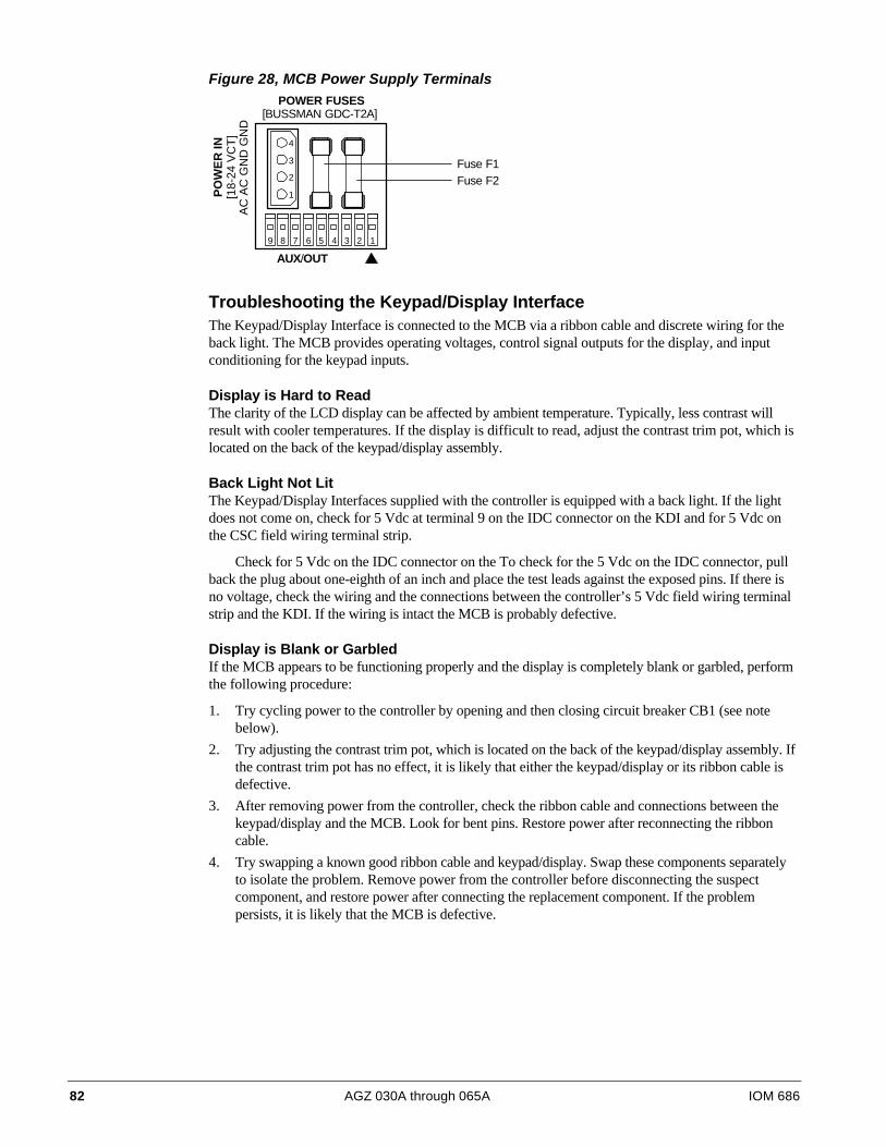
82 AGZ 030A through 065A IOM 686
Figure 28, MCB Power Supply TerminalsPOWER FUSES
[BUSSMAN GDC-T2A]
PO
WE
R IN
[18-
24 V
CT
]A
C A
C G
ND
GN
DAUX/OUT
4
3
2
1
9 8 7 6 5 4 3 2 1
Fuse F1Fuse F2
Troubleshooting the Keypad/Display InterfaceThe Keypad/Display Interface is connected to the MCB via a ribbon cable and discrete wiring for theback light. The MCB provides operating voltages, control signal outputs for the display, and inputconditioning for the keypad inputs.
Display is Hard to ReadThe clarity of the LCD display can be affected by ambient temperature. Typically, less contrast willresult with cooler temperatures. If the display is difficult to read, adjust the contrast trim pot, which islocated on the back of the keypad/display assembly.
Back Light Not LitThe Keypad/Display Interfaces supplied with the controller is equipped with a back light. If the lightdoes not come on, check for 5 Vdc at terminal 9 on the IDC connector on the KDI and for 5 Vdc onthe CSC field wiring terminal strip.
Check for 5 Vdc on the IDC connector on the To check for the 5 Vdc on the IDC connector, pullback the plug about one-eighth of an inch and place the test leads against the exposed pins. If there isno voltage, check the wiring and the connections between the controller’s 5 Vdc field wiring terminalstrip and the KDI. If the wiring is intact the MCB is probably defective.
Display is Blank or GarbledIf the MCB appears to be functioning properly and the display is completely blank or garbled, performthe following procedure:
1. Try cycling power to the controller by opening and then closing circuit breaker CB1 (see notebelow).
2. Try adjusting the contrast trim pot, which is located on the back of the keypad/display assembly. Ifthe contrast trim pot has no effect, it is likely that either the keypad/display or its ribbon cable isdefective.
3. After removing power from the controller, check the ribbon cable and connections between thekeypad/display and the MCB. Look for bent pins. Restore power after reconnecting the ribboncable.
4. Try swapping a known good ribbon cable and keypad/display. Swap these components separatelyto isolate the problem. Remove power from the controller before disconnecting the suspectcomponent, and restore power after connecting the replacement component. If the problempersists, it is likely that the MCB is defective.
IOM 686 AGZ 030A through 065A 83
Troubleshooting Analog InputsAn analog input, such as a temperature sensor, is connected to the ADI board. The analog input is thenconditioned by the ADI board. The conditioned input is transferred to the MCB via a ribbon cable.
Analog Input not Read by the MCBIf the MCB appears to be functioning properly and the analog input is not being read by the MCB,perform the following procedure:
1. Try cycling power to the controller by opening and then closing circuit breaker CB1.
2. Check the ribbon cable, power wiring connector, and the field wiring connections from the analoginput device. Look for bent pins, cable on backwards, or mis-wires. Restore power afterreconnecting all cables and wires.
3. If the problem persists, try swapping a known good ribbon cable or analog input device. Swapthese components separately to isolate the problem. Remove power from the controller beforedisconnecting the suspect component, and restore power after connecting the replacementcomponent. If the problem persists, it is likely that the MCB is defective.
Troubleshooting Digital InputsA digital input device is connected to the ADI board. 24 Vac, supplied by transformer T2, is sent tothe digital input device via a supply wire. When a contact in the digital device makes, a return signal issent back to the ADI board. The signal is then conditioned by the ADI board. The conditioned digitalinput is then sent to the MCB via a ribbon cable.
Digital Input not Read by the MCBIf the MCB appears to be functioning properly and the digital input is not being read by the MCB,perform the following procedure:
1. Try cycling power to the controller by opening and then closing circuit breaker CB1.
2. Check the ribbon cable, power wiring connector, and the field wiring connections from the digitalinput device. Look for bent pins, cable on backwards, or mis-wires. Restore power afterreconnecting all cables and wires.
3. If the problem persists, try swapping a known good ribbon cable or a digital input device. Swapthese components separately to isolate the problem. Remove power from the controller beforedisconnecting the suspect component, and restore power after connecting the replacementcomponent. If the problem persists, it is likely that the MCB is defective.
Troubleshooting Output BoardsEach output on the Output Board consists of a solid-state relay, an LED, 5-amp fuse, and an MOV(metal oxide varistor).
Normally, when the MCB commands an output to energize, the solid-state relay contacts willclose and the LED will glow. The contacts of each solid-state relay are in series with a 5-amp fuse.These fuses resemble small resistors and are located on the board adjacent to the relays they serve (seeFigure 4). The fuses are pressed into place. They can be removed with a needle nose pliers. The MOV,which is located on the underside of the output board, protects the solid-state relay from high transientvoltages. MOVs are part of the output board and cannot be replaced.
Following are troubleshooting procedures for various symptoms of output board problems
Note: It should be possible to determine whether a solid-state relay is defective by usingthese procedures.

84 AGZ 030A through 065A IOM 686
Figure 29, Output Board Relay Socket
1
2
3
4
5
LED
Fuse
Test Resistor330-680 Ohm
*250V ~ 50/60 Hz
*120V ~ 50/60 Hz
WARNINGElectric shock hazard. Can cause severe injury or death. Even when power to the panel isoff, solid-state relay socket terminals 1 and 2 on the output board could be connected tohigh voltage. Avoid them.
One LED OutIf one of the Output Board LEDs fails to illuminate when the MCB is commanding the associatedoutput to energize, perform the following procedure:
1. Remove power from the controller by opening CB1. Swap the suspect relay with a known goodrelay. Try to choose a relay that will not affect unit operation. Restore power by closing CB1.If the LED does not light, go to step 2.If the LED lights, the suspect relay is defective.
2. Remove power from the controller. Check the ribbon cable and connections between the OB andthe MCB. Look for bent pins.If the cable and connections are intact, go to step 3.
3. Remove the relay from the suspect socket. Install a 330-680 ohm resistor between terminals 3 and5 as shown in Figure 4. Restore power by placing CB1 to the ON position. The LED should lightregardless of the controller’s command. If the output LED illuminates, it is likely that the MCB is defective. If the output LED does not illuminate, the output board is defective.
All LEDs OutIf the MCB is commanding at least two outputs to energize and none of the Output Board LEDs arelit, perform the following procedure:
1. Verify that 5 Vdc is present at the Output Board’s power terminals.If 5 Vdc is not present, go to step 2.If 5 Vdc is present, check the ribbon cable and connections between the output board and MCB.Look for bent pins. If the cable and connections are intact, the Output Board or the MCB isdefective.
IOM 686 AGZ 030A through 065A 85
2. Remove power from the controller by placing CB1 to the OFF position. Disconnect at least onewire from the power input terminals of the Output Board. The resistance should not be less than3000 ohms.If the resistance is greater than the acceptable value, go to step 3.If the resistance is less than the acceptable value, the Output Board is defective.
3. Check the discrete wiring and connections between the Output board and the Controller. Aux/Outterminal strip and the field wiring terminal strip.
Note: The MCB Aux/Out connector plug terminals displace wire insulation to make contactwith the conductor. If a faulty Aux/Out connections is suspected, try pressing down on thewire in the terminals with a small screwdriver.
LED Lit, Output not EnergizedIf the LED of a suspect output is lit but the load connected to it is not energized, and everything isintact between the MCB and the coil side of the relay, perform the following procedure to isolate theproblem:
1. Verify that 24 or 120 Vac power is present at the suspect output’s screw terminal on the OutputBoard.
2. Remove power from the controller by opening CB1. Pull the 5-amp fuse on the contact side ofthe relay and check it for continuity with an ohmmeter.If the fuse is not bad, reinstall it and go to step 3.If the fuse is bad, replace it and inspect the load and associated wiring before restoring power.Note that a fuse from an unused output can be substituted for the bad fuse.
3. Remove power from the controller by opening CB1. Swap the suspect relay with a known goodrelay. Try to choose a relay that will not affect unit operation. Restore power by closing CB1.If the output load energizes, the suspect relay is bad. Replace the relay.If the output load does not energize (when LED is lit again), check the load circuit wiring andcomponents.
Output Energized, LED not LitIf the LED of a suspect output is not lit, but the load connected to it is energized, either the Solid-Staterelay or the MOV is bad. The Solid-State relay contacts and the MOV, which are in parallel, can bothfail closed. Perform the following procedure to isolate the problem:
1. Remove power from the controller by opening CB1. Pull the Solid-State relay from the suspectoutput’s socket.
2. Restore power by closing CB1.If the output load remains energized when there is no relay in the socket, the output’s MOV hasfailed and the Output Board must be replaced.If the output load de-energizes, the relay that was pulled is defective.
Contact ChatterContact chatter is very rapid opening and closing of contacts. It is usually caused by low voltage at theelectromechanical relay or contactor coil. If contact chatter is occurring on a relay or contactorconnected to one of the Output Board Solid-State relays, it is also possible that a faulty connectionexists on the power supply terminals of the Aux/Out plug connector on the MCB. In very rareinstances, contact chatter can be caused by a faulty Solid-State relay. Perform the following procedureto isolate the problem.
1. Verify that the voltage at the load’s power supply and at the Solid-State relay contacts is adequate.
2. Remove power from the controller by opening CB1. Swap the suspect relay with a known goodrelay. Try to choose a relay that will not affect unit operation. Restore power by closing CB1.If the chatter does not stop, go to step 3.If the chatter stops, the suspect relay is defective. Replace the relay.

86 AGZ 030A through 065A IOM 686
3. Remove power from the controller by opening CB1. Try to improve the connections in theAux/Out plug insulation displacement terminals by pressing down on the wires with a smallscrewdriver.
4. Check all other wiring and connectors for bent pins or mis-wires.If the chatter does not stop, the electromechanical relay or contactor is probably defective.
Troubleshooting Solid-State RelaysAs shown on the unit wiring diagrams, the Solid-State relays on the Output Boards all have normallyopen “contacts.” Actually, these contacts do not exist as they do in an electromechanical relay. Insteadof using contacts to switch the load, the Solid-State relay changes its resistance from low (closed),when it is energized, to high (open), when it is de-energized. (This high resistance is approximately100K ohms.) Because the output circuit through the Solid-State relay remains continuous regardlessof whether the relay is energized, troubleshooting a Solid-State relay with a voltmeter can be tricky.
In a typical circuit, a power source is connected across a single relay output and a load. In thiscircuit, a Solid-State relay will behave like an electromechanical relay. If the relay is energized, therelay output will be hot. If the relay is de-energized, voltage cannot be measured at the relay output.
The circuit shown in Figure 23 is similar to a typical circuit; the difference is that there is an openset of contacts, or a disconnection between the relay output and the load. In this circuit, a Solid-Staterelay will not behave like an electromechanical relay. if the Solid-State relay is energized, the relayoutput will be hot (as expected). However, if the Solid-State relay is de-energized, the relay output willstill appear to be hot. This is because the relay output and the voltmeter form a continuous circuit inwhich the relay’s resistance, though high, is insignificant compared to the voltmeter’s resistance.
This means that nearly all the voltage is dropped across the voltmeter. Therefore, the voltmeterindicates that voltage is present. If a low wattage light bulb of the appropriate voltage is used insteadof a voltmeter, the bulb’s low resistance will load the circuit enough to eliminate the false voltageindication. In this situation, an incandescent test lamp is a better tool than a voltmeter.
Figure 30, Testing a Typical Relay Circuit Figure 31, Testing a Relay Circuit with aDisconnection
M10
0V
115 VAC
Output BoardDO 13
28 27
NeutralM10
115V
115 VAC
Output BoardDO 13
28 27
Neutral

IOM 686 AGZ 030A through 065A 87
Notes

13600 Industrial Park Boulevard, P.O. Box 1551, Minneapolis, MN 55440 USA (612) 553-5330