air cooled screw chillers - daikin.rs€¦ · air cooled screw chillers ewad-cz (inverter) x (high...
TRANSCRIPT
D - EIMAC00607-11EU - 1/156
Inverter
Installation, Operation and Maintenance Manual
Air cooled screw chillers
EWAD-CZ (Inverter) X (High Efficiency) 640 ~ C18 Cooling capacity from 635 to 1800 kW
Refrigerant: R-134a
English 9
Deutsch 16Français 25
Nederlands 34
Español 41
Italiano 48
�������� 55
Português 64
��� 71
Swedish 78
Norsk 85
Finnish (Suomi) 92
Połysk 99
�ech 106
Hrvat 113
Magyar 120
Român 127
Slovenski 134
�������� 141
Slovenský 148English language: Original instructionsAll other language: Translation of the Original instructions
Installation, Operation and Maintenance Manual D – EIMAC00607-11EU

D - EIMAC00607-11EU - 2/156
A – Typical refrigerant circuit - Water inlet and outlet are indicative. Please refer to the machine dimensional diagrams for exact water connections. A – Typischer Kühlkreislauf – Wasser-Ein- und Ausgang sind unverbindlich. Bitte beziehen Sie sich auf die Geräteabmessungs-Diagramme für genaue Wasseranschlüsse. A – Circuit de refroidissement typique – L'arrivée et la sortie d'eau sont reportés à titre indicatif. Veuillez vous reporter aux schémas dimensionnels de la machine pour identifier les
raccordements exacts de l’eau. A – Typisch koelmiddelcircuit – Waterintlaat en –uitlaat zijn indicatief. Zie de dimensionele diagrams van de machine voor de juiste wateraansluitingen. A – Circuito de refrigeración típico - la entrada y la salida de agua son indicativas. Consulte los diagramas de dimensiones de la máquina para conocer las conexiones de agua
exactas. A – Tipico circuito refrigerante – L’ingresso e l’uscita dell’acqua sono indicativi. Consultare i diagrammi dimensionali delle macchine per i collegamenti idraulici esatti. A – ������ ������� �������� � !�� – " ��#�$% &�!�'�� ��� &(�'�� �&#�� &)��� &�'&�����%. *���# (�& !�� '��+#������ '��!��!&�� ��� ��$��%����, +�� ��, ��#�-&), !��' !&�,
�&#��. A – Circuito típico refrigerante – Entrada e saída de água são indicativas. Consultar os diagramas dimensionais da máquina para as conexões certas da água. A – ./�01��/02 �30/� 4��1��50/� – 67�025 � 827�025 83137�3831025 3/85�/�9 73��:�02 ��;< 1�9 7��=5��. >�9 37�515�50�9 7���=5/�38 731��?@50�9
83137�3831� �515/ @�/28�/< 1�025 ��A���/024 @5�/5B5 3A3�138�0�9. A – Typisk kylkrets – Vattenledningens inlopp och utlopp är ungefärliga. Se maskinens dimensionsdiagram för exakta vattenanslutningar. A – Typisk kjølemediekrets - vanninntak og -uttak er kun antydninger. Se maskinens måltegninger for nøyaktige vanntilkoblinger. A – Tyypillinen jäähdytyspiiri – Vedentulo- ja poistoaukot ovat viitteelliset. Katso tarkat vesiliitännät koneen mittakaavioista. A – Typowy obwód czynnika chłodniczego – wskazane miejsce dopływu i odpływu wody ma charakter poglCdowy. Dokładne miejsca podłCczeD instalacji wodnej wskazano na rysunkach wymiarowanych. A – Typický chladící obvod – PEívod a odvov dvoudy jsou jednoznaFné. PEesný postup pEipojení vody viz nákresy stroje. A – TipiFni rashladni krug – ulaz i izlaz za vodu su samo za indikaciju. Pogledajte mjerne skice stroja ako želite toFan položaj prikljuFaka za vodu. A - Tipikus hGtH áramkör - A vízbeömlH- és kiömlHnyílás jelzésszerG. A pontos összeköttetésekért lásd a berendezés szerkezeti rajzát. A – Circuit de rIcire tipic – Intrarea �i ie�irea pentru apI au rol indicativ. VI rugIm sI consulta�i diagramele ma�inii cu dimensiunile pentru conexiunile exacte la apI. A – TipiFen tokokrog hladilnega sredstva – vodni dovod in odvod sta indikativna. Za natanFne vodne povezave glejte diagrame dimenzij naprave.A – J�7�@0� 34��1�/5�0� 85���� – 6310�/5 8431385 � �:431� � ��:�/5�0�. K3�9, 0�7��85/5 7��8�� 1�����=�/5 �:=5��/5 0� =�;�0�/� :� /3@0�/5 8310� 8��:��. A – Typický obvod chladiacej zmesi. Vstup a výstup vody sú indikatívne.. Presná poloha prípojok vody je vyznaFená na rozmerových výkresoch zariadenia.

D - EIMAC00607-11EU - 3/156
A

D - EIMAC00607-11EU - 4/156
B – Typical refrigerant circuit with heat recovery - Water inlet and outlet are indicative. Please refer to the machine dimensional diagrams for exact water connections. B- Typischer Kühlkreislauf mit Wärmerückgewinnung – Wasser-Ein- und Ausgang sind unverbindlich. Bitte beziehen Sie sich auf die Geräteabmessungs-Diagramme für genaue
Wasseranschlüsse B – Circuit de refroidissement typique avec récuperation de chaleur – L'arrivée et la sortie d'eau sont reportés à titre indicatif. Veuillez vous reporter aux schémas dimensionnels
de la machine pour identifier les raccordements exacts de l’eau. B - – Typisch koelmiddelcircuit – Waterintlaat en –uitlaat zijn indicatief. Zie de dimensionele diagrams van de machine voor de juiste wateraansluitingen.B – Circuito de refrigeración típico con recuperación de calor – La entrada y la salida de agua son indicativas. Consulte los diagramas de dimensiones de la máquina para conocer
las conexiones de agua exactas. B – Tipico circuito refrigerante con recupero di calore – L’ingresso e l’uscita dell’acqua sono indicativi. Consultare i diagrammi dimensionali delle macchine per i collegamenti
idraulici esatti. � – ������ ������� �������� � !�� �& ������!� L&#������, – " ��#�$% &�!�'�� ��� &(�'�� �&#�� &)��� &�'&�����%. *���# (�& !�� '��+#������ '��!��!&�� ��� ��$��%����,
+�� ��, ��#�-&), !��' !&�, �&#��. B – Circuito típico refrigerante com recuperação de calor - – Entrada e saída de água são indicativas. Consultar os diagramas dimensionais da máquina para as conexões certas da
água. B – ./�01��/02 �30/� 4��1��50/� �5�75��M�5 /57�� – 67�025 � 827�025 83137�3831025 3/85�/�9 73��:�02 ��;< 1�9 7��=5��. >�9 37�515�50�9
7���=5/�38 731��?@50�9 83137�3831� �515/ @�/28�/< 1�025 ��A���/024 @5�/5B5 3A3�138�0�9. B – Typisk kylkrets med värmeåtervinning – Vattenledningens inlopp och utlopp är ungefärliga. Se maskinens dimensionsdiagram för exakta vattenanslutningar. B – Typisk kjølemediekrets med varmegjenvinning - vanninntak og -uttak er kun antydninger. Se maskinens måltegninger for nøyaktige vanntilkoblinger. B – Tyypillinen jäähdytyspiiri lämmön talteenotolla - Vedentulo- ja poistoaukot ovat viitteelliset. Katso tarkat vesiliitännät koneen mittakaavioista. B – Typowy obwód czynnika chłodniczego z odzyskiem ciepła. Wskazane miejsce dopływu i odpływu wody ma charakter poglCdowy. Dokładne miejsca podłCczeD instalacji wodnej wskazano na rysunkach wymiarowanych. B – Typciký chladící obvod s rekuperací teplat – PEívod a odvod vody jsou prNkazné. PEesné zapojení viz nákresy stroje. B – TipiFni rashladni krug s povratom topline – ulaz i izlaz za vodu su samo za indikaciju. Pogledajte mjerne skice stroja ako želite toFan položaj prikljuFaka za vodu. B - Tipikus hGtH áramkör hHvisszanyerH berendezéssel - A vízbeömlH- és kiömlHnyílás jelzésszerG. A pontos összeköttetésekért lásd a berendezés szerkezeti rajzát. B – Circuit de rIcire tipic cu recuperare de cIldurI. Intrarea �i ie�irea pentru apI au rol indicativ. VI rugIm sI consulta�i diagramele ma�inii cu dimensiunile pentru conexiunile
exacte la apI. B – TipiFen tokokrog hladilnega sredstva z obnavljanjem toplote – vodni dovod in odvod sta indikativna. Za natanFne vodne povezave glejte diagrame dimenzij naprave.. B – J�7�@0� 34��1�/5�0� 85���� 8�:/�03898�05 0� /37��0�/� – 6310�/5 8431385 � �:431� � ��:�/5�0�. K3�9, 0�7��85/5 7��8�� 1�����=�/5 �:=5��/5 0�
=�;�0�/� :� /3@0�/5 8310� 8��:��. B – Typický obvod chladiacej zmesi s regeneráciou tepla. Vstup a výstup vody sú indikatívne. Presná poloha prípojok vody je vyznaFená na rozmerových výkresoch zariadenia.

D - EIMAC00607-11EU - 5/156
B

D - EIMAC00607-11EU - 6/156
�
� English Deutsch Français Nederlands Español Italiano1 Compressor Verdichter Compresseur Compressor Compresor Compressore 2 Discharge shut off valve Vorlaufabsperrventil Robinet de refoulement Persafsluiter Grifo de salida Rubinetto di mandata 3 High-pressure transducer Hochdrucksensor Transducteur haute pression Omzetter hoge druk Transductor de alta presión Trasduttore alta pressione 4 Service port Wartungsklappe Port de maintenance Dienstluikje Portillo para asistencia Valvola di servizio
5 High-pressure safety valve Hochdruck-Sicherheitsventil Soupape de sécurité haute pression Veiligheidsklep hoge druk Válvula de seguridad de alta presión Valvola di sicurezza alta pressione 6 Axial ventilator Axialventilator Ventilateur axial Axiale ventilator Ventilador axial Ventilatore assiale 7 Condenser coil Verflüssigerregister Batterie à condensation Condensorgroep Batería condensadora Batteria condensante 8 Load Valve Lastventil Vanne de charge Laadklep válvula de carga Valvola di caricamento
9 Liquid line isolating valve Absperrventil Flüssigkeitsleitung Vanne d'isolement de la ligne du liquide Afsluiter vloeistoflijn Válvula de corte de la línea del líquido
Valvola isolante linea del liquido
10 Dehydration filter Entwässerungsfilter Filtre déshydrateur Dehydratatiefilter Filtro deshidratador Filtro deidratatore
11 Liquid and humidity indicator Flüssigkeits- und Feuchtigkeitsanzeige
Indicateur de liquide et humidité Vloeistof- en vochtigheidsindicator Indicador de líquido y humedad Indicatore di liquido e umidità
12 Economiser solenoid valve Solenoidventil Economiser Vanne solénoïde économiseur Magneetklep economiser Válvula solenoide economizador Valvola solenoide economizzatore
13 Economiser thermostatic expansion valve
Thermostatisches Expansionsventil Economiser
Détendeur thermostatique économiseur Thermostatisch expansieventiel economiser
Válvula de expansión termostática del economizador
Valvola di espansione termostatica economizzatore
14 Economiser Economiser Économiseur Economiser Economizador Economizzatore 15 Electronic expansion valve Elektronisches Expansionsventil Détendeur électronique Elektronisch expansieventiel Válvula de expansión electrónica Valvola di espansione elettronica 16 Evaporator Verdampfer Evaporateur Verdamper Evaporador Evaporatore
17 Low-pressure safety valve Niederdruck-Sicherheitsventil Soupape de sécurité à basse pression Veiligheidsklep lage druk Válvula de seguridad de baja presión Valvola di sicurezza a bassa pressione
18 (ST) Suction temperature probe Ansaugtemperaturfühler Sonde de température aspiration Temperatuursonde aanzuiging Sonda de temperatura en aspiración Sonda temperatura aspirazione 19 (EP) Low-pressure transducer Niederdrucksensor Transducteur basse pression Omzetter lage druk Transductor de baja presión Trasduttore bassa pressione
20 Suction shut off valve Absperrventil Saugleitung Robinet d'aspiration Aanzuiging afsluitklep Grifo de aspiración Rubinetto di aspirazione
21 Liquid injection shut off valve Asperrventil der Flüssigkeitseinspritzung
Vanne d’arrêt de l’injection du liquide Afsluitklep voor vloeistofinjectie Grifo de inyección de líquido Valvola di chiusura a iniezione liquida
22 Liquid injection mesh filter Gewebefilter der Flüssigkeitseinspritzung
Filtre à mailles pour l’injection du liquide Filter met mazen voor vloeistofinjectie
Filtro de malla de inyección de líquido Filtro in mesh a iniezione liquida
23 Liquid injection solenoid valve Solenoidventil zur Flüssigkeitseinspritzung
Vanne solénoïde pour injection du liquide Magneetklep voor vloeistofinjectie Válvula solenoide para inyección de líquido
Valvola solenoide per iniezione di liquido
24 (F13) High-pressure pressure switch Maximum-Druckwächter Pressostat haute pression Drukregelaar hoge druk Presostato de alta presión Pressostato alta pressione25 (DT) Discharge temperature sensor Auslauf-Temperatur-Sensor Capteur de la température de refoulement Perstemperatuursensor Sensor de temperatura de salida Sensore di temperatura di scarico 26 (OP) Oil pressure transducer Öldrucksensor Transducteur pression de l'huile Omzetter oliedruk Transductor de presión del aceite Trasduttore pressione olio
27 Water inlet connection Anschluss Wasserzulauf Raccordement de l’arrivée d’eau Aansluiting ingang water Conexión de la entrada de agua Collegamento di ingresso acqua
28 (EEWT) Water entering temperature probe Temperaturfühler Wasserzulauf Sonde de température entrée eau Temperatuursonde watertoevoer Sonda de temperatura de entrada del agua
Sonda temperatura ingresso acqua
29 Water outlet connection Anschluss Wasserauslauf Raccordement de la sortie d’eau Aansluiting uitgang water Conexión de la salida de agua Connessione uscita acqua
30 (ELWT) Water leaving temperature probe Temperaturfühler Wasserauslauf Sonde de température sortie eau Temperatuursonde wateruitlaat Sonda de temperatura de salida del agua
Sonda temperatura uscita acqua
31 (R5) Evaporator heater Verdampfer-Heizer Réchauffeur de l’évaporateur Verwarming verdamper Calentador del evaporador Riscaldatore con evaporatore 32 Heat recovery Wärmerückgewinnung Récupération de chaleur Warmteterugwinning Recuperación de calor Recupero del calore 33 Water inlet connection Anschluss Wasserzulauf Raccordement de l’arrivée d’eau Waterinvoeraansluiting Conexión de la entrada de agua Collegamento di ingresso dell’acqia 34 Water outlet connection Verdichter Raccordement de la sortie d’eau Wateruitvoeraansluiting Conexión de la salida de agua Collegamento di uscita dell’acqua

D - EIMAC00607-11EU - 7/156
� �������� Português ��� � Swedish Norsk Finnish Połyskk �esky1 O����&!�%, Compressor P3=7�53� Kompressor Kompressor Kompressori SprQRarka Kompresor
2 O�#�++���!���% -��-)'�&�#�%, Torneira de mandada
S/5@03 ���7�0 0�0��05/�0�� Tryckavstängningsventil Avstengningsventil på utløp Poiston tyhjennysventtiili Zawór tłoczny VýtlaFný kohoutek
3 T&���#�� �, ����%,�)&!�,
Transdutor de alta pressão >�/@�� 823�3�31�8�50�9
Högtrycksomvandlare Høytrykksomformer Korkeapaineanturi Przetwornik wysokiego ciUnienia
Transduktor vysokého tlaku
4 V�#�� -��L&)�, Válvula de segurança de alta pressão
.=3/�383 �?� Servicelucka Serviceluke Huoltoluukku Drzwiczki serwisowe Servisní dvíEka
5 W��-)'� �!X��&)�, ����%,�)&!�,
Bateria condensante Y�5134��0�/5�<02 ���7�0 73 823�3=1�8�50�?
Högtrycks säkerhetsventil Sikkerhetsventil for høytrykk Korkeapaine turvaventtiili Zawór bezpieczeDstwa wysokiego ciUnienia
BezpeFnostní ventil vysokého tlaku
6 *�&��!�%#�, �(��� Secção de subarrefecimento integrada
S583 850/��9/3� Axialfläkt Aksialventilator Aksiaalipuhallin Wentylator osiowy Axiální ventilátor
7 T����#)� !�������!�, Ventilador axial P30150�/3� Kondensor Kondensatorbatteri Jäähdytyskierukka WQRownica skraplacza KondenzaFní baterie
8 W��-)'� ��(�!�, X�#�)��Torneira de isolamento da linha do líquido
Z���:�� Valve Laddningsventil Load Valve Latausventtiili Zawór wlotowy Zatížení ventilu
9 W��-)'� �������!�,+#���%, �+#�� Filtro desidrator
S/5@03 ���7�0��1��8��@5�3 ��0��
Isoleringsventil vätskeledning
Avstengningsventil på flytende linje
Nestelinjan eristysventtiili Zawór odcinajCcy liniQ płynu IzolaFní kohoutek linie kapaliny
10 [)��#� �X�+#��!�, Indicador de líquido e humidade \��</�-3;�/5�< Avfuktningsfilter Avfuktningsfilter Kuivaussuodatin Filtr odwadniacza Filtr dehydrátoru
11 ]�'&�(� �+#�� ����+#�!)�,
Válvula de expansão eletrónica ^01���/3� 8��B03/� Vätske- och fuktvisare Væske- og fuktighets-seglass Neste- ja kosteusmittari Wska_nik płynu i wilgoci Ukazatel kapaliny a vlhkosti
12 "�&��#���+�����% -��-)'�economiser
Válvula solenóide para injeção de líquido
.3�503�102 ���7�0`�303=� :5�� Magnetventil kylring
Magnetventil for fødevannsforvarmer
Säästöyksikön solenoidiventtiili
Elektromagnetyczny zawór ekonomizera
Solenoidní ventil ekonomizátoru
13 a&#��!�����% -��-)'�&�����!�, economiser
Evaporador de expansão direta J5�=3/�/�@5�� ��;���/5�<02 ���7�0`�303=� :5��
Termostatisk expansionsventil kylring
Termostatisk ekspansjonsventil for fødevannsforvarmer
Säästöyksikön termostaattinen paisuntaventtiili
Termostatyczny zawór rozprQRny ekonomizera
Tepelný expanzní ventil ekonomizátoru
14 Economiser Válvula de segurança a baixa pressão
b�303=� :5� Kylring Fødevannsforvarmer Säästöyksikkö Ekonomizer Ekonomizátor
15 "�&��#����% -��-)'�&�����!�,
Torneira de aspiração b�5�/�3002 ��;���/5�<02 ���7�0
Elektronisk expansionsventil Elektronisk ekspansjonsventil Elektroninen paisuntaventtiili
Elektroniczny zawór rozprQRny Expanzní elektronický ventil
16 �(����!�%, Porta para assistência ^7���/5�< Förångare Evaporator Höyrystin Parownik Evaporátor
17 W��-)'� �!X��&)�,$����%, �)&!�, Conexão para saída de água
Y�5134��0�/5�<02 ���7�0 73 0�:�3=1�8�50�?
Lågtrycks säkerhetsventil Sikkerhetsventil for lavtrykk Matalapaine turvaventtiili Zawór bezpieczeDstwa niskiego ciUnienia
BezpeFnostní ventil nízkého tlaku
18 (ST) *�!L��%#�, L&#���#�!)�,���##�X�!�, Conexão para entrada de água
>�/@�� /5=75��/�2 0�8�28�0�� Sond sugtemperatur Temperaturføler i innløp Imun lämpötila-anturi Sonda temperatury zasysania Tepelná sonda nasávání
19 (EP) T&���#�� �, $����%,�)&!�,
Subarrefecedor (ou economizador) adicional
>�/@�� 0�:�3�3 1�8�50�9 Lågtrycksomvandlare Lavtrykksomformer Matalapaineanturi Przetwornik niskiego ciUnienia Transduktor nízkého tlaku
20 O�#�++���!���% -��-)'����##�X�!�,
Válvula solenóide subarrefecedor (ou economizador) adicional
S/5@03 ���7�0 0�8�28�0�� Sugavstängningsventil Avstengningsventil på innløp Imuhana Zawór ssawny Nasávací kohoutek
21 O�#�++���!���% -��-)'� +$�!�, �+#��
Válvula de expansão termostática subarrefecedor (ou economizador) adicional
67�2�� B�1�3/�:�73�02 ���7�0
Avstängningsventil för vätskeinjicering
Flytende injeksjon stengeventil
Nesteen ruiskutuksen sulkuventtiili
Zawór zamykajCcy wtrysk płynu
VstEikování uzavírací ventil
22 [)��#� �� +����, +$�!�,�+#��
Permutador de recuperação de calor c�1��5 �0�5�M��5/@�/2 d��</� Nätfilter för vätskeinjicering Flytende injeksjon mesh filter
Nesteen ruiskutuksen siiviläverkko
Elektrozawór zamykajCcy wtrysk płynu
VstEikování sítkový filtr
23 "�&��#���+�����% -��-)'��&��!��� �+#��
Entrada da água de recuperação de calor
.3�503�102 ���7�087�2��8�0�9 B�1�3/�
Magnetventil för vätskeinjicering
Magnetventil for væskeinjeksjon
Solenoidiventtiili nesteruiskutukseen
Zawór elektromagnetyczny wtryskiwania płynu
Solenoidní ventil pro vstEikování kapaliny
24 (F13) e�������, �)&!�, ����%,�)&!�,
Saída da água de recuperação de calor
�5�5 823�3�3 1�8�50�9 Högtrycksmätare Høytrykkspressostat Korkeapaine kytkin Presostat wysokiego ciUnienia Presostat vysokého tlaku
25 (DT) *�!L��%#�, L&#���#�!)�,&�#�%, Sonda da temperatura de aspiração
>�/@�� /5=75��/�2��:�91�
Temperatursond för uttömning
Utslipp temperatursensor Vastuuvapaus lämpötila-anturi
Czujnik temperatury na wyjUciu
Vybití teplotní Fidlo
26 (OP) T&���#�� �, �)&!�,��'���
Transdutor de baixa pressão >�/@�� 1�8�50�9 =��� Oljetrycksomvandlare Oljetrykkomformer Öljypaineanturi Przetwornik ciUnienia oleju Transduktor tlaku oleje
27 O��'&!� &�!�'�� �&#�� Transdutor de pressão do óleo 6431 8312 Anslutning vatteninlopp Forbindelse for vanninnløp Veden sisäänmenoliitos PodłCczenie dopływu wody Zapojení vstup vody
28 (EEWT) *�!L��%#�, L&#���#�!)�,&�!�'�� �&#��
Transdutor de alta pressão >�/@�� /5=75��/�28312 0� 84315
Temperatursond inloppsvatten
Temperaturføler for vann i inngang
Veden sisäänmenon lämpötila-anturi
Sonda temperatury dopływu wody
Tepelná sonda vstup vody
29 O��'&!� &(�'�� �&#�� Óleo/sensor temperatura de descarga
62431 8312 Anslutning vattenutlopp Forbindelse for vannutløp Veden ulostuloliitos PodłCczenie odpływu wody Zapojení výstup vody
30 (ELWT) *�!L��%#�, L&#���#�!)�,&(�'�� �&#�� Pressóstato alta pressão
>�/@�� /5=75��/�28312 0� 824315
Temperatursond utloppsvatten
Temperaturføler for vann i utgang
Ulostulevan veden lämpötila-anturi
Sonda temperatury odpływu wody
Tepelná sonda vstup vody
31 (R5) a&#����%#�, &(����!�% Sonda de temperatura da entrada da água
^7���/5�< 0���58�/5�< Förångarvärmare Varmeveksler med varmegjenvinning
Haihduttimen lämmitin Podgrzewacz parownika Výparník
32 *�����!� L&#������,Sonda de temperatura da saída da água
f/���:�M�9 /57�� Värmeåterställning Varmegjenvinning Lämmön talteenotto Odzysk ciepła Rekuperace tepla
33 O��'&!� &�!�'�� �&#�� Sonda de temperatura da entrada da água de recuperação de calor
Y31��?@50�5 83120� 84315
Anslutning för vatteninlopp Forbindelse for vanninnløp Vedenottoputken liitäntä PodłCczenie dopływu wody Vtokové hrdlo
34 O��'&!� &(�'�� �&#��Sonda de temperatura da saída da água de recuperação de calor
Y31��?@50�5 8312 0�824315 Anslutning för vattenutlopp Forbindelse for vannutløp Vedenpoistoputken liitäntä PodłCczenie odpływu wody Odpadní hrdlo
D - EIMAC00607-11EU - 8/156
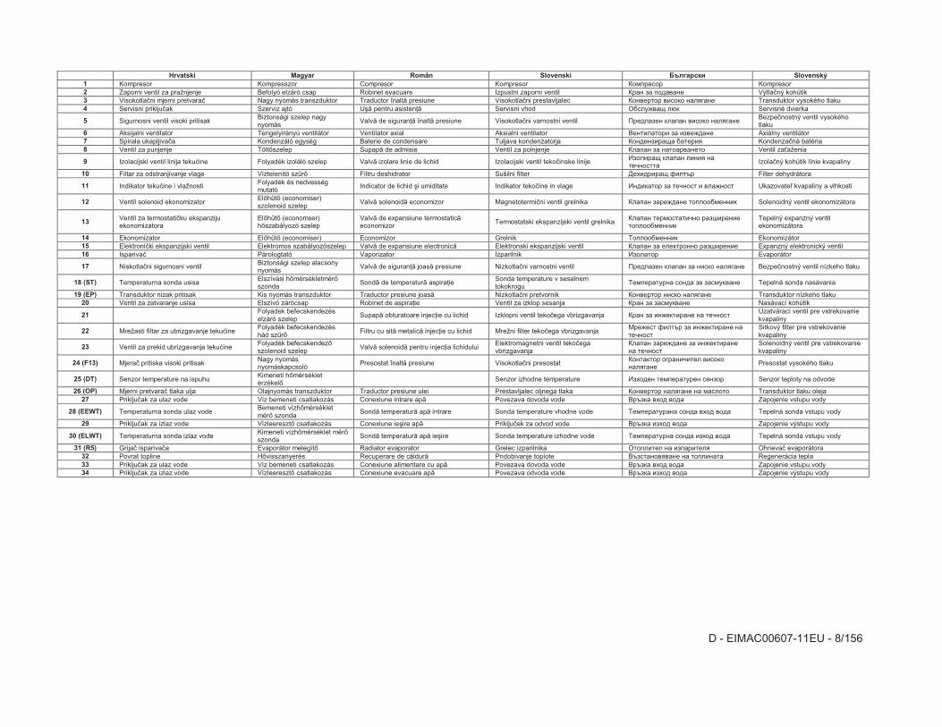
� Hrvatski Magyar Român Slovenski �������� Slovenský 1 Kompresor Kompresszor Compresor Kompresor P3=7�53� Kompresor 2 Zaporni ventil za pražnjenje Befolyó elzáró csap Robinet evacuare Izpustni zaporni ventil P��0 :� 731�8�05 VýtlaFný kohútik 3 VisokotlaFni mjerni pretvaraF Nagy nyomás transzduktor Traductor înaltI presiune VisokotlaFni prestavljalec P3085�/3� 8�3�3 0��9��05 Transduktor vysokého tlaku 4 Servisni prikljuFak Szerviz ajtó UgI pentru asistenhI Servisni vhod SA�B8�i �?� Servisné dvierka
5 Sigurnosni ventil visoki pritisak Biztonsági szelep nagy nyomás
ValvI de siguranhI înaltI presiune VisokotlaFni varnostni ventil Y�517�:50 ���7�0 8�3�3 0��9��05 BezpeFnostný ventil vysokého tlaku
6 Aksijalni ventilator Tengelyirányú ventilátor Ventilator axial Aksialni ventilator 650/���/3�� :� �:85B1�05 Axiálny ventilátor 7 Spirala ukapljivaFa Kondenzáló egység Baterie de condensare Tuljava kondenzatorja P30150:���i� A�/5��9 KondenzaFná batéria 8 Ventil za punjenje TöltHszelep SupapI de admisie Ventil za polnjenje P��7�0 :� 0�/3��8�05/3 Ventil zajaženia
9 Izolacijski ventil linija tekukine Folyadék izoláló szelep ValvI izolare linie de lichid Izolacijski ventil tekoFinske linije ^:3����i ���7�0 ��0�9 0�/5@03//�
IzolaFný kohútik línie kvapaliny
10 Filtar za odstranjivanje vlage VíztelenítH szGrH Filtru deshidrator Sušilni filter >54�1����i d��/�� Filter dehydrátora
11 Indikator tekukine i vlažnosti Folyadék és nedvesség mutató
Indicator de lichid gi umiditate Indikator tekoFine in vlage ^01���/3� :� /5@03/ � 8��B03/ Ukazovatel kvapaliny a vlhkosti
12 Ventil solenoid ekonomizator ElHhGtH (economiser) szolenoid szelep
ValvI solenoidI economizor MagnetotermiFni ventil grelnika P��7�0 :��5B1�05 /37�33A=500�� Solenoidný ventil ekonomizátora
13 Ventil za termostatiFku ekspanziju ekonomizatora
ElHhGtH (economser) hHszabályozó szelep
ValvI de expansiune termostaticIeconomizor
Termostatski ekspanzijski ventil grelnika P��7�0 /5�=3/�/�@03 ��:;��50�5/37�33A=500��
Tepelný expanzný ventil ekonomizátora
14 Ekonomizator ElHhGtH (economiser) Economizor Grelnik J37�33A=500�� Ekonomizátor 15 ElektroniFki ekspanzijski ventil Elektromos szabályozószelep ValvI de expansiune electronicI Elektronski ekspanzijski ventil P��7�0 :� 5�5�/�3003 ��:;��50�5 Expanzný elektronický ventil 16 IsparivaF Párologtató Vaporizator Izparilnik ^:3��/3� Evaporátor
17 NiskotlaFni sigurnosni ventil Biztonsági szelep alacsony nyomás
ValvI de siguranhI joasI presiune NizkotlaFni varnostni ventil Y�517�:50 ���7�0 :� 0��3 0��9��05 BezpeFnostný ventil nízkeho tlaku
18 (ST) Temperaturna sonda usisa Elszívási hHmérsékletmérHszonda
SondI de temperaturI aspirahie Sonda temperature v sesalnem tokokrogu
J5=75��/�0� 301� :� :�=�8�05 Tepelná sonda nasávania
19 (EP) Transduktor nizak pritisak Kis nyomás transzduktor Traductor presiune joasI NizkotlaFni pretvornik P3085�/3� 0��3 0��9��05 Transduktor nízkeho tlaku 20 Ventil za zatvaranje usisa Elszívó zárócsap Robinet de aspirahie Ventil za izklop sesanja P��0 :� :�=�8�05 Nasávací kohútik
21 Folyadek befecskendezés elzáró szelep
SupapI obturatoare injechie cu lichid Izklopni ventil tekoFega vbrizgavanja P��0 :� �0B5�/���05 0� /5@03/Uzatvárací ventil pre vstrekovanie kvapaliny
22 Mrežasti filtar za ubrizgavanje tekukine Folyadék befecskendezés háó szGrH
Filtru cu sitI metalicI injechie cu lichid Mrežni filter tekoFega vbrizgavanja K�5B5/ d��/�� :� �0B5�/���05 0�/5@03/
Sitkový filter pre vstrekovanie kvapaliny
23 Ventil za prekid ubrizgavanja tekukine Folyadék befecskendezHszolenoid szelep
ValvI solenoidI pentru injechia lichidului Elektromagnetni ventil tekoFega vbrizgavanja
P��7�0 :��5B1�05 :� �0B5�/���050� /5@03/
Solenoidný ventil pre vstrekovanie kvapaliny
24 (F13) MjeraF pritiska visoki pritisak Nagy nyomás nyomáskapcsoló
Presostat înaltI presiune VisokotlaFni presostat P30/��/3� 3���0�@�/5� 8�3�30��9��05
Presostat vysokého tlaku
25 (DT) Senzor temperature na ispuhu Kimeneti hHmérséklet érzékelH Senzor izhodne temperature ^:43150 /5=75��/�50 50:3� Senzor teploty na odvode
26 (OP) Mjerni pretvaraF tlaka ulja Olajnyomás transzduktor Traductor presiune ulei Prestavljalec oljnega tlaka P3085�/3� 0��9��05 0� =��3/3 Transduktor tlaku oleja 27 PrikljuFak za ulaz vode Víz bemeneti csatlakozás Conexiune intrare apI Povezava dovoda vode 6��:�� 8431 831� Zapojenie vstupu vody
28 (EEWT) Temperaturna sonda ulaz vode Bemeneti vízhHmérséklet mérH szonda
SondI temperaturI apI intrare Sonda temperature vhodne vode J5=75��/��0� 301� 8431 831� Tepelná sonda vstupu vody
29 PrikljuFak za izlaz vode VízleeresztH csatlakozás Conexiune iegire apI PrikljuFek za odvod vode 6��:�� �:431 831� Zapojenie výstupu vody
30 (ELWT) Temperaturna sonda izlaz vode Kimeneti vízhHmérséklet mérHszonda
SondI temperaturI apI iegire Sonda temperature izhodne vode J5=75��/�0� 301� �:431 831� Tepelná sonda vstupu vody
31 (R5) GrijaF isparivaFa Evaporátor melegítH Radiator evaporator Grelec izparilnika S/37��/5� 0� �:7���/5�9 OhrievaF evaporátora 32 Povrat topline HHvisszanyerés Recuperare de cIldurI Pridobivanje toplote 6�:/�03898�05 0� /37��0�/� Regenerácia tepla 33 PrikljuFak za ulaz vode Víz bemeneti csatlakozás Conexiune alimentare cu apI Povezava dovoda vode 6��:�� 8431 831� Zapojenie vstupu vody 34 PrikljuFak za izlaz vode VízleeresztH csatlakozás Conexiune evacuare apI Povezava odvoda vode 6��:�� �:431 831� Zapojenie výstupu vody

D - EIMAC00607-11EU - 9/156
ENGLISH - ORIGINAL INSTRUCTIONS
This manual is an important supporting document for qualified personnel but it is not intended to replace such personnel.
Thank you for purchasing this chiller
READ THIS MANUAL CAREFULLY BEFORE INSTALLING AND STARTING UP THE UNIT. IMPROPER INSTALLATION COULD RESULT IN ELECTRIC SHOCK, SHORT-CIRCUIT, LEAKS, FIRE OR OTHER DAMAGE TO THE EQUIPMENT OR INJURE TO PEOPLE. THE UNIT MUST BE INSTALLED BY A PROFESSIONAL OPERATOR/TECHNICIAN UNIT STARTUP HAS TO BE PERFORMED BY AUTHORIZED AND TRAINED PROFESSIONAL ALL ACTIVITIES HAVE TO BE PERFORMED ACCORDING TO LOCAL LAWS AND REGULATION. UNIT INSTALLATION AND START UP IS ABOSOLUTELY FORBIDDEN IF ALL INSTRUCTION CONTAINED IN THIS MANUAL ARE NOT CLEAR.IF CASE OF DOUBT CONTACT THE MANUFACTURER REPRESENTATIVE FOR ADVICE AND INFORMATION.
Description
The unit you bought is an “air cooled chiller”, a machine aimed to cool water (or water-glycol mixture) within the limits described in the following. The unit operazion is based on vapour compression, condensation and evaporation according to reverse Carnot cycle.The main components are: - Screw compressor to rise the refrigerant vapour pressure
from evaporation pressure to condensation pressure - Evaporator, where the low pressure liquid reqrigerant
evaporates so cooling the water - Condenser, where high pressure vapour condensate
rejecting heat removed from the chilled water in the atmosphere thanks to an air cooled heat exchanger.
- Expansion valve allowing to reduced the pressure of condensed liquid from coinsensation pressue to evaporation pressure
General InformationAll units are delivered with wiring diagrams, certified drawings, nameplate; and DOC (Declaration Of Conformity); these documents show all technical data for the unit you have bought and they MUST BE CONSIDERED ESSENTIAL DOCUMENTS OF THIS MANUAL
In case of any discrepancy between this manual and the equipment’s documents please refer to on board documents. In case of any doubt contact the manufacturer representative..
The purpose of this manual is to allow the installer and the qualified operator to ensure proper installation, commissioning and maintenance of the unit, without any risk to people, animals and/or objects.
Receiving the unit
The unit must be inspected for any possible damage immediately upon reaching final place of installation. All components described in the delivery note must be inspected and checked. Should the unit be damaged, do not remove the damaged material and immediately report the damage to the transportation company and request they inspect the unit.. Immediately report the damage to the manufacturer representative, a set of photographs are helpful in recognizing responsibility Damage must not be repaired before the inspection of the transportation company representative. Before installing the unit, check that the model and power supply voltage shown on the nameplate are correct. Responsibility for any damage after acceptance of the unit cannot be attributed to the manufacturer.
Operating limits
Storing Environmental conditions must be within the following limits: Minimum ambient temperature : -20°C Maximum ambient temperature : 57°C Maximum R.H. : 95% not condensing Storing below the minimum temperature may cause damage to components. Storing above the maximum temperature causes opening of safety valves. Storing in condensing atmosphere may damage electronic components.
Operation Operation is allowed within the limits mentioned in Figure 2. The unit must be operated with an evaporator water flow rate between 50% and 140% of nominal flow rate (at standard operating conditions). Operation out of the mentioned limits may damage the unit. In case of doubts contact manufacturer representative.
Figure 1 - Description of the labels applied to the electrical panel
Label Identification 1 – Non flammable gas symbol 6 – Electrical hazard symbol 2 – Gas type 7 – Hazardous Voltage warning 3 – Unit nameplate data 8 – Cable tightening warning 4 – Manufacturer’s logo 9 – Lifting instructions 5 – Water circuit filling warning

D - EIMAC00607-11EU - 10/156
Figure 2 - Operating limits
���
���
���
�
��
��
��
��
��
�
��� � � �� �� � � � �� �� �� �
Safety The unit must be firmly secured to the soil. It is essential to observe the following instructions: − The unit can only be lifted using the lifting points marked
in yellow fixed to its base. − It is forbidden to access the electrical components without
having opened the unit main switch and switched off the power supply.
− It is forbidden to access the electrical components without using an insulating platform. Do not access the electrical components if water and/or moisture are present.
− Sharp edges and the surface of the condenser section could cause injury. Avoid direct contact and use adeguate protection device
− Switch off power supply, by opening the main switch, before servicing the cooling fans and/or compressors. Failure to observe this rule could result in serious personal injury.
− Do not introduce solid objects into the water pipes while the unit is connected to the system.
− A mechanical filter must be installed on the water pipe connected to the heat exchanger inlet.
− The unit is supplied with safety valves, that are installed both on the high-pressure and on the low-pressure sides of the refrigerant circuit.
It is absolutely forbidden to remove all protections of moving parts.
In case of sudden stop of the unit, follow the instructions on the Control Panel Operating Manual which is part of the on-board documentation delivered to the end user.
It is strongly recommended to perform installation and maintenance with other people. In case of accidental injury or unease, it is necessary to: - keep calm - press the alarm button if present in the installation site - move the injured person in a warm place far from the unit
and in rest position
- contact immediately emergency rescue personnel of the building or the Health Emergency Service
- wait without leaving the injured person alone until the rescue operators come
- give all necessary information to the the rescue operators
Avoid installing the chiller in areas that could be dangerous during maintenance operations, such as platforms without parapets or railings or areas not complying with the clearance requirements around the chiller.
Noise The unit is a source of noise mainly due to rotation of compressors and fans. The noise level for each model size is listed in sales documentation. If the unit is correctly installed, operated and manteined the noise emission level do not require any special protection device to operate continuosly close to the unit without any risk. In case of installation with special noise requirements it could be necessary to install additional sound attenuation devices.
Moving and lifting Avoid bumping and/or jolting during loading/unloading unit from the truck and moving it. Do not push or pull the unit from any part other than the base frame. Secure the unit inside the truck to prevent it from moving and causing damages. Do not allow any part of the unit to fall during transportation or loading/unloading. All units of the series are supplied with lifting points marked in yellow. Only these points may be used for lifting the unit, as shown in the following. Use spacing bars to prevent damage to the condensation bank. Position these above the fan grills at a distance of at least 2.5 metres.
Both the lifting ropes and the spacing bars must be strong enough to support the unit safely. Please check the unit’s weight on the unit nameplate.
Evap Leaving Water Temperature (°C)
Am
bie
nt T
em
per
atu
re (
°C)
Speedtroll required (below -10°C Amb.)
Fan Speed Modulation required (below 10°C)
In this area Chiller may operate at part load
Operation with Glycol (below 4°C Evap LWT)

D - EIMAC00607-11EU - 11/156
The unit must be lifted with the utmost attention and care following lifting label instructions; lift unit very slowly, keeping it perfectly level..
Positioning and assembly All units are designed for installation outdoors, either on balconies or on the ground, provided that the installation area
is free of obstacles that could reduce air flow to the condensers coil. The unit must be installed on a robust and perfectly level foundation; should the unit be installed on balconies or roofs, it might be necessary to use weight distribution beams.
Figure 3 - Lifting the unit
2 compressors unit 3 compressors unit
For installation on the ground, a strong concrete base, at least 250 mm thickness and wider than the unit must be provided. This base must be able to support the weight of the unit. If the uni is installed in places that are easily accessible to people and animals, it is advisable to install protection grids for the condenser and compressor sections. To ensure best performance on the installation site, the following precautions and instructions must be followed: − Avoid air flow recirculation. − Make sure that there are no obstacles to hamper air flow. − Make sure to provide a strong and solid foundation to
reduce noise and vibrations. − Avoid installation in particularly dusty environments, in
order to reduce soiling of condensers coils. − The water in the system must be particularly clean and all
traces of oil and rust must be removed. A mechanical water filter must be installed on the unit’s inlet piping.
Minimum space requirements It is fundamental to respect minimum distances on all units in order to ensure optimum ventilation to the condenser coils. When deciding where to position the unit and to ensure a proper air flow, the following factors must be taken into consideration: − avoid any warm air recirculation − avoid insufficient air supply to the air-cooled condenser.
Both these conditions can cause an increase of condensing pressure, which leads to a reduction in energy efficiency and refrigerating capacity. Any side of the unit must be accessible for post-installation maintenance operations. Figure 3 shows the minimum space required. Vertical air discharge must not be obstructed. If the unit is surrounded by walls or obstacles of the same height as the unit, this must be installed at a distance no lower
than 2500 mm. If these obstacles are higher, the unit must be installed at a distance no lower than 3000 mm. Should the unit be installed without observing the recommended minimum distances from walls and/or vertical obstacles, there could be a combination of warm air recirculation and/or insufficient supply to the air-cooled condenser which could cause a reduction of capacity and efficiency. In any case, the microprocessor will allow the unit to adapt itself to new operating conditions and deliver the maximum available capacity under any given circumstances, even if the lateral distance is lower than recommended, unless the operating conditions should affect personel safety or unit reliability. When two or more units are positioned side by side, a distance of at least 3600 mm between condenser banks is recommended. For further solutions, please consult manufacturer representative.
Sound protection When sound levels require special control, great care must be exercised to isolate the unit from its base by appropriately applying anti-vibration elements (supplied as an option). Flexible joints must be installed on the water connections, as well.
Water piping Piping must be designed with the lowest number of elbows and the lowest number of vertical changes of direction. In this way, installation costs are reduced considerably and system performance is improved. The water system should have: 1. Anti-vibration mountings in order to reduce transmission of
vibrations to the structures. 2. Isolating valves to isolate the unit from the water system
during maintenance. 3. Flow switch.

D - EIMAC00607-11EU - 12/156
4. Manual or automatic air venting device at the system’s highest point.; drain device at the system’s lowest point.
5. Neither the evaporator nor the heat recovery device must be positioned at the system’s highest point.
6. A suitable device that can maintain the water system under pressure (expansion tank, etc.).
7. Water temperature and pressure indicators to assist the operator during service and maintenance.
Figure 4 - Minimum clearance requirements
8. A filter or device that can remove particles from the fluid. The use of a filter extends the life of the evaporator and pump and helps to keep the water system in a better condition.
9. Evaporator has an electrical resistance with a thermostat that ensures protection against water freezing at ambient temperatures as low as –25°C. All the other water piping/devices outside the unit must therefore be protected against freezing.
10. The heat recovery device must be emptied of water during the winter season, unless an ethylene glycol mixture in appropriate percentage is added to the water circuit.
11. If case of unit substitution, the entire water system must be emptied and cleaned before the new unit is installed. Regular tests and proper chemical treatment of water are recommended before starting up the new unit.
12. In the event that glycol is added to the water system as anti-freeze protection, pay attention to the fact that suction pressure will be lower, the unit’s performance will be lower and water pressure drops will be greater. All unit-protection systems, such as anti-freeze, and low-pressure protection will need to be readjusted.
13. Before insulating water piping, check that there are no leaks.

D - EIMAC00607-11EU - 13/156
Figure 5 - Water piping connection for evaporator
1. Pressure Gauge 2. Flexible connector 3. Flow switch 4. Temperature probe
5. Isolation Valve 6. Pump 7. Filter
Figure 6 - Water piping connection for heat recovery exchangers
1. Pressure Gauge 2. Flexible connector 3. Temperature probe
4. Isolation Valve 5. Pump 6. Filter
Water treatment Before putting the unit into operation, clean the water circuit. Dirt, scales, corrosion debrits and other other material can accumulate inside the heat exchanger and reduce its heat exchanging capacity. Pressure drop can increase as well, thus reducing water flow. Proper water treatment therefore reduces
the risk of corrosion, erosion, scaling, etc. The most appropriate water treatment must be determined locally, according to the type of system and water characteristics. The manufacturer is not responsible for damage to or malfunctioning of equipment caused by failure to treat water or by improperly treated water.
Table 1 - Acceptable water quality limits pH (25°C) 6,8÷8,0 Total Hardness (mg CaCO3 / l) < 200 Electrical conductivity µS/cm (25°C) <800 Iron (mg Fe / l) < 1.0 Chloride ion (mg Cl - / l) <200 Sulphide ion (mg S2 - / l) None Sulphate ion (mg SO2
4- / l) <200 Ammonium ion (mg NH4
+ / l) < 1.0 Alkalinity (mg CaCO3 / l) <100 Silica (mg SiO2 / l) < 50

D - EIMAC00607-11EU - 14/156
Evaporator and recovery exchangers anti-freeze protection All evaporators are supplied with a thermostatically controlled anti-freeze electrical resistance, which provides adequate anti-freeze protection at temperatures as low as –25°C. However, unless the heat exchangers are completely empty and cleaned with anti-freeze solution, additional methods should also be used against freezing. Two or more of below protection methods should be considered when designing the system as a whole: − Continuous water flow circulation inside piping and
exchangers − Addition of an appropriate amount of glycol inside the
water circuit − Additional heat insulation and heating of exposed piping − Emptying and cleaning of the heat exchanger during the
winter season It is the responsibility of the installer and/or of local maintenance personnel to ensure that described anti-freeze methods are used. Make sure that appropriate anti-freeze protection is maintained at all times. Failing to follow the instructions above could result in unit damage. Damage caused by freezing is not covered by the warranty.
Installing the flow switch To ensure sufficient water flow through the evaporator, it is essential that a flow switch be installed on the water circuit. The flow switch can be installed either on the inlet or outlet water piping. The purpose of the flow switch is to stop the unit in the event of interrupted water flow, thus protecting the evaporator from freezing. The manufacturer offers, as optional, a flow switch that has been selected for this purpose. This paddle-type flow switch is suitable for heavy-duty outdoor applications (IP67) and pipe diameters in the range of 1” to 6”. The flow switch is provided with a clean contact which must be electrically connected to terminals shown in the wiring diagram. Flow switch has to be tune to intervene when the evaporator water flow is lower than 50% of nomila flow rate.
Heat recovery Units may be optionally equipped with heat recovery system. This system in made by a water cooled heat exchanger located on the compressors discharge pipe and a dedicated managment of condensing pressure. To gurantee compressor operation within its envelope, units with heat recovery cannot operate with water temperature of the heat recovery water lower than 28°C. It is a responsability of plant designer and chiller installer to grantee the respect of this value (e.g. using recirculating bypass valve)
Electrical Installation
General specifications All electrical connections to the unit must be carried out in compliance with laws and regulations in force. All installation, management and maintenance activities must be carried out by qualified personnel. Refer to the specific wiring diagram for the unit you have bougth. Should the wiring diagram not be on the unit or should it have been lost, please contact your manufacturer representative, who will send you a copy. In case of discrepance between wiring diagram and electrical panel/cables please contact the manufacturer representative.
Only use copper conductors. Failure to use copper conductors could result in overheating or corrosion at connection points and could damage the unit. To avoid interference, all control wires must be connected separately from the power cables. Use different electrical passage ducts for this purpose. Before servicing the unit in any way, open the general disconnecting switch on the unit’s main power supply. When the unit is off but the disconnecting switch is in the closed position, unused circuits are live, as well.
Never open the terminal board box of the compressors before having opened the unit’s general disconnecting switch.
Contemporaneity of single-phase and three-phase loads and unbalance between phases could cause leakages towards ground up to 150mA, during the normal operation of the units of the series. If the unit includes devices that cause superior harmonics (like VFD and phase cut), the leakage towards ground could increases to very higher values (about 2 Ampere). The protections for the power supply system have to be designed according to the above mentioned values.
Operation
Operator’s responsibilities It is essential that the operator is appropriately trained and becomes familiar with the system before operating the unit. In addition to reading this manual, the operator must study the microprocessor operating manual and the wiring diagram in order to understand start-up sequence, operation, shutdown sequence and operation of all the safety devices. During the unit’s initial start-up phase, a technician authorized by the manufacturer is available to answer any questions and to give instructions as to the correct operating procedures. The operator must keep a record of operating data for every installed unit. Another record should also be kept of all the periodical maintenance and servicing activities. If the operator notes abnormal or unusual operating conditions, he is advised to consult the technical service authorized by the manufacturer.
Routine maintenance Minimum maintenance activities are listed in
Table 2
Service and limited warramty
All units are factory-tested and guaranteed for 12 months as of the first start-up or 18 months as of delivery. These units have been developed and constructed according to high quality standards ensuring years of failure-free operation. It is important, however, to ensure proper and periodical maintenance in accordance with all the procedures listed in this manual and with good practice of machines maintenance. We strongly advise stipulating a maintenance contract with a service authorized by the manufacturer in order to ensure efficient and problem-free service, thanks to the expertise and experience of our personnel. It must also be taken into consideration that the unit requires maintenance also during the warranty period.�It must be borne in mind that operating the unit in an inappropriate manner, beyond its operating limits or not performing proper maintenance according to this manual can void the warranty. Observe the following points in particular, in order to conform to warranty limits: 1. The unit cannot function beyond the specified limits 2. The electrical power supply must be within the voltage
limits and without voltage harmonics or sudden changes. 3. The three-phase power supply must not have un
unbalance between phases exceeding 3%. The unit must stay turned off until the electrical problem has been solved.
4. No safety device, either mechanical, electrical or electronic must be disabled or overridden.
5. The water used for filling the water circuit must be clean and suitably treated. A mechanical filter must be installed at the point closest to the evaporator inlet.
6. Unless there is a specific agreement at the time of ordering, the evaporator water flow rate must never be above 120% and below 80% of the nominal flow rate.
D - EIMAC00607-11EU - 15/156
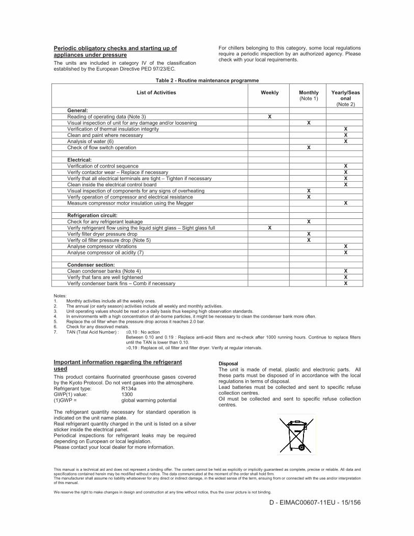
Periodic obligatory checks and starting up of appliances under pressure
The units are included in category IV of the classification established by the European Directive PED 97/23/EC.
For chillers belonging to this category, some local regulations require a periodic inspection by an authorized agency. Please check with your local requirements.
Table 2 - Routine maintenance programme
List of Activities Weekly Monthly (Note 1)
Yearly/Seasonal
(Note 2) General:Reading of operating data (Note 3) XVisual inspection of unit for any damage and/or loosening XVerification of thermal insulation integrity XClean and paint where necessary XAnalysis of water (6) XCheck of flow switch operation X
Electrical:Verification of control sequence XVerify contactor wear – Replace if necessary XVerify that all electrical terminals are tight – Tighten if necessary XClean inside the electrical control board XVisual inspection of components for any signs of overheating XVerify operation of compressor and electrical resistance XMeasure compressor motor insulation using the Megger X
Refrigeration circuit:Check for any refrigerant leakage XVerify refrigerant flow using the liquid sight glass – Sight glass full XVerify filter dryer pressure drop XVerify oil filter pressure drop (Note 5) XAnalyse compressor vibrations XAnalyse compressor oil acidity (7) X
Condenser section:Clean condenser banks (Note 4) XVerify that fans are well tightened XVerify condenser bank fins – Comb if necessary X
Notes: 1. Monthly activities include all the weekly ones. 2. The annual (or early season) activities include all weekly and monthly activities. 3. Unit operating values should be read on a daily basis thus keeping high observation standards. 4. In environments with a high concentration of air-borne particles, it might be necessary to clean the condenser bank more often. 5. Replace the oil filter when the pressure drop across it reaches 2.0 bar. 6. Check for any dissolved metals. 7. TAN (Total Acid Number) : ≤0,10 : No action
Between 0.10 and 0.19 : Replace anti-acid filters and re-check after 1000 running hours. Continue to replace filters until the TAN is lower than 0.10. >0,19 : Replace oil, oil filter and filter dryer. Verify at regular intervals.
Important information regarding the refrigerant used
This product contains fluorinated greenhouse gases covered by the Kyoto Protocol. Do not vent gases into the atmosphere. Refrigerant type: R134a GWP(1) value: 1300 (1)GWP = global warming potential
The refrigerant quantity necessary for standard operation is indicated on the unit name plate. Real refrigerant quantity charged in the unit is listed on a silver sticker inside the electrical panel. Periodical inspections for refrigerant leaks may be required depending on European or local legislation. Please contact your local dealer for more information.
Disposal The unit is made of metal, plastic and electronic parts. All these parts must be disposed of in accordance with the local regulations in terms of disposal. Lead batteries must be collected and sent to specific refuse collection centres. Oil must be collected and sent to specific refuse collection centres.
This manual is a technical aid and does not represent a binding offer. The content cannot be held as explicitly or implicitly guaranteed as complete, precise or reliable. All data and specifications contained herein may be modified without notice. The data communicated at the moment of the order shall hold firm. The manufacturer shall assume no liability whatsoever for any direct or indirect damage, in the widest sense of the term, ensuing from or connected with the use and/or interpretation of this manual.
We reserve the right to make changes in design and construction at any time without notice, thus the cover picture is not binding.

D - EIMAC00607-11EU - 16/156
DEUTSCHE ÜBERSETZUNG DER ENGLISCHEN ORIGINAL-BEDIENUNGSANLEITUNG
Dieses Handbuch liefert dem Fachpersonal hilfreiche Unterstützung, soll und kann dieses Personal aber nicht ersetzen.
Vielen Dank für den Kauf dieses Kühlaggregats
DIESE ANLEITUNG BITTE VOR INSTALLATION UND INBETRIEBNAHME AUFMERKSAM LESEN. BEI EINER UNSACHGEMÄSSEN INSTALLATION KANN ES ZU STROMSCHLAG, KURZSCZHLUSS, LECKAGE, BRAND ODER ANDEREN SCHÄDEN AM GERÄT BZW. VERLETZUNGEN VON PERSONEN KOMMEN. DIE EINHIET IST DURCH FACHPERSONAL ZU INSTALLIEREN. DIE INBETRIEBNAHME DER EINHEIT HAT DURCH ZUGELASSENES UND GESCHULTES FACHPERSONAL ZU ERFOLGEN. ALLE ARBEITEN MÜSSEN UNTER EINHALTUNG DER ÖRTLICHEN GESETZE UND VORSCHRIFTEN AUSGEFÜHRT WERDEN. DIE INSTALLATION UND INBETRIEBNAHME DER EINHEIT IST STRENGSTENS UNTERSAGT, FALLS NICHT ALLE IN DER VORLIEGENDEN ANLEITUNG ENTHALTENEN ANWEISUNGEN EINDEUTIG SEIN SOLLTEN.SCIH IN ZWEIFELSFÄLLEN AN DEN VERTRETER DES HERSTELLERS WENDEN.
Beschreibung
Die erworbene Einheit ist ein „luftgekühltes Kühlaggregat“, d. h. eine Maschine zum Kühlen von Wasser (oder einer Wasser-Glykol-Mischung) in den nachstehend beschriebenen Grenzen. Der Betrieb der Einheit basiert auf der Kompression, Kondensation und Verdunstung von Dampf nach dem umgekehrten Carnot-Zyklus. Die wichtigsten Komponenten sind: - Schraubenverdichter zur Druckerhöhung des
Kühlmitteldampfes vom Verdampfungsdruck auf den Kondensationsdruck.
- Verdampfer, in dem das flüssige Kühlmittel bei geringem Druck verdampft und so das Wasser kühlt.
- Verflüssiger, in dem der Hochdruckdampf kondensiert und dadurch die dem gekühlten Wasser entzogene Wärme mithilfe eines luftgekühlten Wärmetauschers in die Atmosphähre abführt.
- Expansionsventil, mit dem der Druck der kondensierten Flüssigkeit vom Kondensations- auf den Verdampfungsdruck vermindert wird.
Allgemeine InformationAlle Einheiten werden mit Schaltplänen, geprüften
Zeichnungen, Typenschild und DOC (Konformitätserklärung) ausgeliefert; diese Unterlagen zeigen alle technischen Daten der erworbenen Einheit und GELTEN ALS FESTER UND WESENTLICHER BESTANDTEIL DIESER ANLEITUNG.
Für den Fall eines etwaigen Widerspruchs zwischen diesem Handbuch und der Geräteunterlagen, beziehen Sie sich bitte
auf diese. Wenden Sie sich bitte in Zweifelsfällen an den Vertreter des Herstellers.
Mithilfe dieses Handbuchs können Installationstechniker und qualifizierte Benutzer alle notwendigen Schritte zur richtigen Installation, Inbetriebnahme und Wartung der Einheit vornehmen, ohne dass dabei Personen, Tiere und/oder Sachen gefährdet werden.
Empfang der Einheit
Die Einheit muss unmittelbar nach dem Eintreffen an ihrem endgültigen Installationsort auf mögliche Fehler untersucht werden. Alle im Lieferschein aufgeführten Bauteile müssen inspiziert und geprüft werden. Sollte die Einheit beschädigt sein, darf das beschädigte Material nicht entfernt werden, sondern der Schaden ist unverzüglich der Speditionsfirma anzuzeigen und diese zur Inspektion der Einheit aufzufordern. Teilen Sie den Schaden unverzüglich dem Vertreter des Herstellers mit und senden Sie wenn möglich Fotos mit ein, die bei der Ermittlung der Verantwortlichen nützlich sein können. Der Schaden darf nicht repariert werden, bevor die Inspektion durch den Vertreter der Speditionsfirma erfolgt ist.!Vor der Installation der Maschine überprüfen, ob das Modell und die Netzspannung den Angaben auf dem Typenschild entsprechen. Der Hersteller haftet nicht für Schäden, die nach der Abnahme der Maschine entstehen.
Betriebsgrenzen
Lagerung Die Umgebungsbedingungen müssen in folgenden Grenzen liegen: Mindest-Umgebungstemperatur : -20!Höchst-Umgebungstemperatur : 57!Maximale relative Luftfeuchtigkeit : 95% ohne Kondensation Die Lagerung bei einer niedrigeren als der minimalen Temperatur kann zur Beschädigung der Komponenten führen. Bei Lagerung oberhalb der maximalen Temperatur können sich die Sicherheitsventile öffnen. Bei Lagerung in einer Atmosphäre mit Kondenswasserbildung können die elektrischen Bauteile beschädigt werden.
Betrieb Der Betrieb ist innerhalb der in Figure 2 angegebenen Grenzen zulässig. Die Einheit muss mit einem Wasserdurchsatz am Verdampfer betrieben werden, der (unter Standard-Betriebsbedingungen) zwischen 50% und 140% des Nenndurchsatzes liegt. Bei Betrieb außerhalb der genannten Grenzen kann die Einheit beschädigt werden. Sich in Zweifelsfällen bitte an den Vertreter des Herstellers wenden.

D - EIMAC00607-11EU - 155/156

D - EIMAC00607-11EU - 156/156
We reserve the right to make changes in design and construction at any time without notice, thus the cover picture is not binding.
Air cooled screw chillers
EWAD-CZ (Inverter) X (High Efficiency) 640 ~ C18 Cooling capacity from 635 to 1800 kW
����
����
����
����
����
�������������� ��������������� ��������������� ��������������� �����
Zandvoordestraat 300 B-8400 Ostend – Belgium www.daikineurope.com
Daikin units comply with the European regulations that guarantee the safety of the