air-cooled series r helical-rotary chiller rtad 085-100-115-125-145-150-165-180 270 to 630 kw (50...
TRANSCRIPT

Model RTAD 085-100-115-125-145-150-165-180270 to 630 kW (50 Hz)
Integrated Free-CoolingBuilt For the Industrial andCommercial Markets
Air-CooledSeries R®
Helical-rotary Chiller
RLC-PRC024-E4

Introduction
RLC-PRC024-E42
The Trane model RTAD Free Cooling
air-cooled helical-rotary compressor
chiller:
"A solution providing
users energy savings by
using the ambient cold."
Like the standard model RTAD, theFree Cooling version of RTADutilizes the proven design of theTrane helical- rotary compressors.For further information about RTAD,the product catalogue RLC-PRC015-
E4 is available on request from yourlocal Trane representative.
RTAD Free Cooling offers highreliability coupled with acompetitive physical footprint andacoustical performance due to itsadvanced design, low speed/directdrive compressor and proven SeriesR® performance.
The advantages of the model RTADFree Cooling are:• A small footprint compared to a
system where a dry cooler and achiller are used
• One single equipment control
• A wide range of capacities
• A wide range of applications
The Series R® Model RTAD FreeCooling helical-rotary screw chilleris designed for countries that have asignificant yearly number of hoursbelow 0 °C and for applicationswhere cooling is needed yearround.

Contents
3RLC-PRC024-E4
Introduction 2
Application Considerations 4
Selection Procedure 6
General Data 8
Performance Data 10
Electrical Data 17
Mechanical Specifications 19

Application Considerations
RLC-PRC024-E44
Certain application constraintsshould be considered when sizing,selecting and installing Trane air-cooled Series R® chillers. Unit andsystem reliability is often dependentupon properly and completelycomplying with these considerations.When the application varies fromthe guidelines presented, it shouldbe reviewed with your local Tranesales representative.
Cooling capacity in Free
cooling mode:
For each unit, a cooling capacity isprovided at a given condition. Ifthere is a need for more coolingcapacity in Free Cooling mode, thensome alternatives are available.• Allow the Leaving Chilled Water
Temperature to increase inWinter mode.
• Start the free cooling mode at alower ambient temperature. Thetemperature reset point and thefree cooling start will bedetermined by the remainingload inside the building inwinter.
In order to reduce pressure drop
and have a more favorable yearly
energy balance on the overall
installation (chiller and pumps),
Trane recommends making the
selection at 50% nominal water
flow.
Example:• Design load: 400 kW
• Evaporator 7°C / Condenser12°C, 30% Ethylene Glycol
• Ambient in summer mode: 35°C• Free Cooling mode temperature
changeover: 5°CThe unit which will satisfy thoseconditions is the RTAD FC 125 STD.

Application Considerations
5RLC-PRC024-E4
Performance in Free Cooling mode:
Figure 1 - Performance with 50% water flow
Additional Gain in kW and Gain in Pressure Drop
Free Cooling mode temperature changeover:
0°C versus 5°C
Average∆∆ Cooling Capacity
(kW)∆∆ Pressure Drop
Leaving CondenserWaterTemperature
7 °C + 412% - 0.2%
11 °C + 197% - 0.2%
Performance with 50% water flow
161.4
253.3
38.8
127.4
0
50
100
150
200
250
300
7°C 11°CLeaving Chilled Water Temperature
Coo
ling
Cap
acity
(kW
)
0°C5°C
Performance with 50% water flow
Leaving Chilled Water Temperature
Co
olin
g C
apac
ity
(kW
)
Figure 2 - Performance with 100% water flow
Additional Gain in kW and Gain in Pressure Drop
Water Flow changeover:
50% versus 100%
Average∆∆ Cooling Capacity
(kW)∆∆ Pressure Drop
Leaving CondenserWaterTemperature
7 °C + 7% - 72%
11 °C + 7% - 73%
Performance with 100% water flow
149.1
234.6
36.6
120.1
0
50
100
150
200
250
300
7°C 11°CLeaving Chilled Water Temperature
Coo
ling
Cap
acity
(kW
)0°C5°C
Performance with 100% water flow
Leaving Chilled Water Temperature
Co
olin
g C
apac
ity
(kW
)

Selection Procedure SI
units:
The chiller capacity tables cover themost frequently encounteredleaving liquid temperatures. Thetables reflect a 6°C temperaturedrop through the evaporator. Forother temperature drops, apply theappropriate adjustment factors. Forchilled brine selections, refer toTable 7 for Ethylene AdjustmentFactors.
Brine composition:
All selection tables are shown with30% Ethylene Glycol in the coolingloop circuit which is the mostconvenient percentage in order toprotect the unit against freezing.
With Ethylene Glycol:• freezing point without burst
effect = -13°C• freezing point with burst effect =
-50°CTo select a Trane air-cooled RTADFree Cooling chiller, the followinginformation is required:1. Design load in kW of
refrigeration2. The remaining cooling load in
winter3. Design chilled water temperature
drop4. Design leaving chilled water
temperature5. Design ambient temperature
Then there are two ways forproceeding the selection:
A - There is no specification about
Free Cooling mode temperature
changeover.
If one unit can provide the summercooling load but not the wintercooling load then the unit with ahigher size that can handle the FreeCooling capacity required must beselected.
Example:
For a design load of 520 kW at 35°Cwith the condition to have 70%remaining cooling load in winter,which means 364 kW in wintermode at -5°C in order to producewater at 7°C.
RTAD FC 150 STD will match thesummer condition load but in freecooling mode it will only give343.8 kW at -5°C.
In order to satisfy the winter modeconditions, the unit that will bestsuit the conditions requested isRTAD FC 165 STD which gives583 kW in summer mode and421 kW in winter mode.
Refer to table below.
Selection Procedure
RLC-PRC024-E46
RTAD FC 150 RTAD FC 165
Summer Mode 527.9 kW 583.5 kW
Winter Mode
(50% water flow)343.8 kW 421 kW
Match
Mismatch

Selection Procedure
7RLC-PRC024-E4
B - A changeover temperature for
Free Cooling is defined.
If there is a temperature setpointdefined for the beginning of theFree Cooling then the selection ofthe unit has to be done based onthis criterion. For the given wintercooling load, the unit that allowsFree Cooling to run at thetemperature setpoint can beselected using Table 4 or 5.
Evaporator flow rates can bedetermined by using the followingformula:
l/s = kW (Capacity) x 0.261/Temperature Drop (°C)
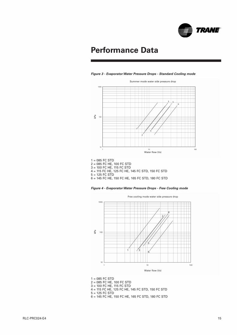
To determine the evaporatorpressure drop we use the flow rate(l/s) and the evaporator waterpressure drop from Figure 3 or 4.
For selection of chilled brine unitsor applications where the altitude issignificantly greater than sea levelor the temperature drop is differentthan 6°C, the performanceadjustment factors from Table 6 and7 should be applied at this point.
For example:
Corrected Capacity = Capacity(unadjusted) x Glycol CapacityAdjustment Factor
Corrected Flow Rate = Flow Rate(unadjusted) x Glycol Flow RateAdjustment Factor
The final unit selection is:
QTY (1) RTAD FC 180 STD (Table 3and 5)
Summer mode:
• Cooling Capacity = 622.8 kW• Entering/Leaving Chilled Water
Temperatures 13/7°C• Ambient 35°C• Chilled Water Flow Rate
= 27.09 l/s• Evaporator Water Pressure Drop
= 95.8 kPa• Power Input = 264.9 kW• Unit COP = 2.35 kW/kWWinter mode:
• Cooling Capacity = 230.1 kW• Entering/Leaving Chilled Water
Temperatures = 9.2/7°C• Ambient 0°C• Chilled Water Flow Rate =
27.29 l/s• Evaporator Water Pressure Drop
= 119.6 kPa• Power Input = 30.5 kW• Unit COP = 7.54 kW/kW
Contact your local Trane salesrepresentative for selections outsideof tabulated conditions.
Selection Procedure -
English units
1 ton = 3.5168 kW
Evaporator flow rate in GPM = 24 xtons / delta T (F)
Delta T (F) = delta T (°C) x 1.8
1 GPM = 0.06309 l/s
1 ft WG = 3 kPa
EER = COP / 0.293
Note:
In this document the PerformanceData given in free cooling mode arefor both 100% and 50% nominalwater flow (see chapter Application
Considerations for more details)

Table 1 - General Data RTAD Free Cooling Standard
(1) Data containing information on two circuits shown as follows: ckt1/ckt2(2) Minimum start-up/operation ambient based on a 2.22 m/s wind across the condenser.(3) Percent minimum load is for total machine at 10°C ambient and 7°C leaving chilled water temp. Not each individual circuit.(4) With aluminum fins
General Data
RLC-PRC024-E48
Unit Size 085 100 115 125 145 150 165 180
Number of Compressors 2 2 2 2 2 2 2 2
Nominal Size (1) (Tons) 40/40 50/50 60/60 70/70 85/70 85/85 100/85 100/100
Evaporator
Evaporator Model EG120 EG140 EG170 EG200 EG200 EG200 EG250 EG250
Water Storage (l) 106 270 222 204 204 204 415 415
Minimum Flow (l/s) 4.1 6 7.3 8.8 8.8 8.8 11.6 11.6
Maximum Flow l/s) 17.3 20.8 24.8 30.7 30.7 30.7 38 38
Free-Cooler
Number of Coils 1 1 1 1 1 1 1 1
Fin series (Fins/ft) 152 152 122 122 152 152 152 152
Number of Rows 4 4 6 6 5 5 5 5
Water Storage (Evap+Free-Cooler) (l) 265 481 538 520 531 531 806 806
Condenser
Number of Coils 2 2 2 2 2 2 2 2
Fin series (Fins/ft) 192 192 192 192 192 192 192 192
Number of Rows 3/3 2/2 3/3 3/3 3/3 3/3 3/3 3/3
Condenser Fans
Quantity (1) 3/3 3/3 3/3 4/4 5/4 5/5 6/5 6/6
Diameter (mm) 762 762 762 762 762 762 762 762
Total Air Flow (m3/s) 17.9/13.0 21.6/15.7 20.4/14.7 23.5/17.2 28.4/20.6 29/21.2 34.2/24.8 34.7/25.4
Nominal Speed (rpm) 935/740 935/740 935/740 935/740 935/740 935/740 935/740 935/740
Motor kW (kW) 1.7/0.85 1.7/0.85 1.7/0.85 1.7/0.85 1.7/0.85 1.7/0.85 1.7/0.85 1.7/0.85
Min Starting/Oper Ambient(2) (°C) -18 -18 -18 -18 -18 -18 -18 -18
General Unit
Refrigerant HFC 134a HFC 134a HFC 134a HFC 134a HFC 134a HFC 134a HFC 134a HFC 134a
No. Of independent Refrigerant Circuits 2 2 2 2 2 2 2 2
% Min. Load (3) 17 17 17 17 17 17 17 17
Weight, Capacities & Dimensions
Refrigerant Charge (1) (kg) 24/24 30/32 35/36 36/37 44/48 44/48 61/59 61/63
Oil Charge (1) (l) 5/5 6/6 8/8 9/9 9/9 9/9 11/10 11/11
Operating Weight (4) (kg) 3781 4587 5387 5542 6395 6607 7978 8064
Shipping Weight (4) (kg) 3456 4000 4721 4895 5727 5939 6960 7048
Length (mm) 3900 4850 4850 4850 5770 5770 6810 6810
Width (mm) 2420 2420 2420 2420 2420 2420 2460 2460
Height (mm) 2603 2603 2623 2623 2643 2643 2743 2743
Water Connection Diameter (mm) 114.3 141.3 141.3 141.3 141.3 141.3 168.3 168.3
Water Connection Type Victaulic Victaulic Victaulic Victaulic Victaulic Victaulic Victaulic Victaulic

General Data
9RLC-PRC024-E4
Table 2 - General Data RTAD Free Cooling High Efficiency
(1) Data containing information on two circuits shown as follows: ckt1/ckt2(2) Minimum start-up/operation ambient based on a 2.22 m/s wind across the condenser.(3) Percent minimum load is for total machine at 10°C ambient and 7°C leaving chilled water temp. Not each individual circuit.(4) With aluminum fins
Unit Size 085 100 115 125 145 150
Number of Compressors Quantity 2 2 2 2 2 2
Nominal Size (1) (Tons) 40/40 50/50 60/60 70/70 85/70 85/85
Evaporator
Evaporator Model EG 140 EG 170 EG 200 EG 200 EG 250 EG 250
Water Storage (l) 270 222 204 204 415 415
Minimum Flow (l/s) 6 7.3 8.8 8.8 11.6 11.6
Maximum Flow l/s) 20.8 24.8 30.7 30.7 38 38
Free-Cooler
Number of Coils 1 1 1 1 1 1
Fin series (Fins/ft) 152 122 152 152 152 152
Number of Rows 4 6 5 5 5 5
Water Storage (Evap+Free-Cooler) (l) 481 538 531 531 806 806
Condenser
Number of Coils 2 2 2 2 2 2
Fin series (Fins/ft) 192 192 192 192 192 192
Number of Rows 3/3 3/3 3/3 3/3 3/3 3/3
Condenser Fans
Quantity (1) 3/3 4/4 4/4 5/5 6/5 6/6
Diameter (mm) 762 762 762 762 762 762
Total Air Flow (m3/s) 20.8/15.1 23.5/17.2 26/18.9 28.9/21.2 34.1/24.8 34.7/25.4
Nominal Speed (rpm) 935/740 935/740 935/740 935/740 935/740 935/740
Motor kW (kW) 1.7/0.85 1.7/0.85 1.7/0.85 1.7/0.85 1.7/0.85 1.7/0.85
Min Starting/Oper Ambient(2) (°C) -18 -18 -18 -18 -18 -18
General Unit
Refrigerant HFC 134a HFC 134a HFC 134a HFC 134a HFC 134a HFC 134a
No. Of independent Refrigerant Circuits 2 2 2 2 2 2
% Min. Load (3) 17 17 17 17 17 17
Weight, Capacities & Dimensions
Refrigerant Charge (1) (kg) 32/34 35/36 42/45 42/45 59/61 59/61
Oil Charge (1) (l) 5/5 6/6 9/9 9/9 10/10 10/10
Operating Weight (4) (kg) 4725 5198 5995 6094 7929 7983
Shipping Weight (4) (kg) 4138 4532 5327 5426 6909 6965
Length (mm) 4850 4850 5770 5770 6810 6810
Width (mm) 2420 2420 2420 2420 2460 2460
Height (mm) 2603 2623 2643 2643 2743 2743
Water Connection Diameter (mm) 141.3 141.3 141.3 141.3 168.3 168.3
Water Connection Type Victaulic Victaulic Victaulic Victaulic Victaulic Victaulic

Table 3 - Standard cooling mode
Ambient air temperature (°C)
30 35 40
LCWT (°C) CC PI COP CC PI COP CC PI COPUnit Size (30%EG) (kW) (kW) (kW/KW) (kW) (kW) (kW/KW) (kW) (kW) (kW/KW)
RTAD 085 FC STD 7 290.4 100.3 2.9 12.6 192.1 271.0 107.4 2.5 11.8 167.8 251.1 115.3 2.2 10.9 144.5
9 308.2 103.7 3.0 13.4 214.4 287.7 110.9 2.6 12.5 187.4 266.7 118.9 2.2 11.6 161.5
11 326.2 107.2 3.0 14.2 238.4 304.7 114.6 2.7 13.2 208.5 282.6 122.7 2.3 12.3 179.9
RTAD 100 FC STD 7 338.5 118.0 2.9 14.7 94.3 315.6 125.7 2.5 13.7 82.3 292.3 134.3 2.2 12.7 70.8
9 358.7 122.3 2.9 15.6 104.9 334.6 130.2 2.6 14.6 91.6 310.0 138.9 2.2 13.5 78.9
11 379.5 126.8 3.0 16.5 116.4 354.2 134.8 2.6 15.4 99.9 328.2 143.7 2.3 14.3 87.6
RTAD 115 FC STD 7 399.2 149.6 2.7 17.4 129.3 371.4 161.2 2.3 16.2 112.3 342.8 174.0 2.0 14.9 96.2
9 421.7 155.2 2.7 18.3 142.9 392.1 167.0 2.3 17.1 124.1 361.9 180.1 2.0 15.7 106.3
11 444.5 161.0 2.8 19.3 157.4 413.2 173.1 2.4 18.0 136.6 381.6 186.3 2.0 16.6 116.8
RTAD 125 FC STD 7 467.4 183.8 2.5 20.4 112.2 435.0 197.7 2.2 19.0 97.7 402.3 212.8 1.9 17.5 83.9
9 493.8 190.5 2.6 21.5 123.9 459.7 204.6 2.2 20.0 107.8 424.8 220.0 1.9 18.5 92.6
11 520.1 197.5 2.6 22.6 136.2 484.3 211.8 2.3 21.0 118.5 447.7 227.4 2.0 19.4 101.7
RTAD 145 FC STD 7 532.5 192.0 2.8 23.2 144.8 498.3 206.0 2.4 21.7 127.2 463.5 221.4 2.1 20.2 110.5
9 564.1 199.0 2.8 24.5 160.9 527.9 220.6 2.4 23.0 141.3 491.0 228.8 2.1 21.3 122.7
11 596.1 206.2 2.9 25.9 178.1 557.8 220.6 2.5 24.2 156.4 518.4 236.4 2.2 22.5 135.7
RTAD 150 FC STD 7 564.8 214.2 2.6 24.6 162.4 527.9 229.6 2.3 23.0 142.4 490.3 246.4 2.0 21.4 123.3
9 596.8 222.1 2.7 26.0 179.6 557.8 237.7 2.3 24.3 157.4 518.0 254.8 2.0 22.5 136.3
11 629.2 230.4 2.7 27.3 197.9 588.0 246.2 2.4 25.5 173.4 545.8 263.4 2.1 23.7 150.0
RTAD 165 FC STD 7 621.1 224.3 2.8 27.0 99.2 583.5 240.2 2.4 25.4 87.9 545.1 257.7 2.1 23.7 77.0
9 658.0 232.6 2.8 28.6 110.3 618.3 248.9 2.5 26.9 97.7 577.1 266.8 2.2 25.1 85.4
11 695.6 241.4 2.9 30.2 122.1 653.4 258.0 2.5 28.4 108.1 609.8 276.2 2.2 26.5 94.5
RTAD 180 FC STD 7 662.6 247.4 2.7 28.9 112.5 622.8 264.9 2.4 27.1 99.7 581.3 284.2 2.0 25.3 87.3
9 700.9 256.9 2.7 30.5 124.8 658.7 274.9 2.4 28.6 110.5 614.8 294.6 2.1 26.7 96.6
11 740.0 266.9 2.8 32.2 137.9 695.3 285.3 2.4 30.2 122.0 648.9 305.5 2.1 28.2 106.6
RTAD 085 FC HE 7 309.5 94.9 3.3 13.5 79.5 289.3 101.3 2.9 12.6 69.7 268.6 108.5 2.5 11.7 60.3
9 329.0 98.0 3.4 14.3 88.9 307.6 104.5 2.9 13.4 78.0 285.7 111.8 2.6 12.4 67.5
11 348.9 101.3 3.4 15.2 99.1 326.4 107.9 3.0 14.2 87.0 303.3 115.3 2.6 13.2 75.4
RTAD 100 FC HE 7 370.7 115.2 3.2 16.1 112.0 346.6 122.7 2.8 15.1 98.3 321.9 131.1 2.5 14.0 85.2
9 393.5 118.8 3.3 17.1 125.0 368.2 126.5 2.9 16.0 109.8 342.3 135.1 2.5 14.9 95.3
11 417.1 122.6 3.4 18.1 139.1 390.4 130.5 3.0 17.0 122.3 363.3 139.2 2.6 15.8 106.2
RTAD 115 FC HE 7 432.9 145.5 3.0 18.9 96.8 405.5 156.1 2.6 17.7 85.2 377.0 168.0 2.2 16.4 74.1
9 488.5 155.6 3.1 20.0 108.3 431.2 161.3 2.7 18.8 95.4 401.3 173.4 2.3 17.5 83.0
11 405.5 156.1 2.6 17.7 85.1 457.5 166.7 2.7 19.9 106.3 425.9 178.9 2.4 18.5 92.5
RTAD 125 FC HE 7 504.3 178.9 2.8 22.0 130.2 472.7 191.9 2.5 20.6 114.8 440.3 206.1 2.1 19.2 100.0
9 535.6 185.0 2.9 23.3 145.4 502.2 198.1 2.5 21.8 128.2 467.7 212.5 2.2 20.3 111.7
11 567.6 191.2 3.0 24.7 161.9 532.1 204.6 2.6 23.1 142.7 495.9 219.2 2.3 21.5 124.4
RTAD 145 FC HE 7 545.5 183.7 3.0 23.7 77.1 513.1 196.6 2.6 22.3 68.5 479.7 210.9 2.3 20.9 60.2
9 579.9 189.9 3.1 25.2 86.3 545.8 203.0 2.7 23.7 76.7 510.7 217.4 2.3 22.2 67.3
11 615.5 196.3 3.1 26.7 96.2 579.2 209.6 2.8 25.2 85.5 542.0 224.2 2.4 23.5 75.1
RTAD 150 FC HE 7 581.7 204.5 2.8 25.3 87.4 546.9 218.6 2.5 23.8 77.5 511.0 234.2 2.2 22.2 67.9
9 617.6 211.6 2.9 26.9 97.4 580.3 225.9 2.6 25.2 86.4 542.3 241.7 2.2 23.6 75.7
11 653.8 219.0 3.0 28.4 108.3 614.8 233.5 2.6 26.7 96.0 574.3 249.5 2.3 25.0 84.1
Notes :1. Temperature drop = 6°C2. 30% ethylene glycol3. Ratings based on sea level altitude and evaporator fouling factor of 0.0176 m² K/kW4. Consult Trane representative for performance at temperatures outside of the ranges shown5. CC = Cooling capacity6. PI (kW) = Power Input (Compressor + Fans + Control Power)7. COP = Coefficient of performance (CC/PI).8. Interpolation between points is permissible. Extrapolation is not permitted.
Performance Data
RLC-PRC024-E410
Water flow rate
Evp(l/s)
WaterPressure
Drop(kPa)
Water flow rate
Evp(l/s)
WaterPressure
Drop(kPa)
Water flow rate
Evp(l/s)
WaterPressure
Drop(kPa)

Performance Data
11RLC-PRC024-E4
Table 4 - Free cooling mode, 50% water flow
Ambient air temperature (°C)
0 -5
LCWT (°C) CC PI COP ECWT CC PI COP ECWTUnit Size (30%EG) (kW) (kW) (kW/KW) (°C) (kW) (kW) (kW/KW) (°C)
RTAD 085 FC STD 7 108.1 15.5 7.0 12.6 5.9 49.3 190.0 15.5 12.2 16.9 5.9 49.1
9 136.1 15.5 8.8 14.7 6.3 73.9 218.5 15.4 14.2 18.1 6.3 73.7
11 170.0 15.4 11.1 17.7 6.6 81.4 254.3 15.3 16.6 21.0 6.6 81.2
RTAD 100 FC STD 7 139.0 14.6 9.5 12.3 6.9 33.0 243.8 14.7 16.6 16.3 6.9 32.9
9 180.0 14.5 12.4 15.5 7.3 36.3 286.2 14.6 19.6 19.3 7.3 36.2
11 221.2 14.5 15.3 18.5 7.7 39.9 328.7 14.5 22.7 22.1 7.7 39.8
RTAD 115 FC STD 7 152.4 14.8 10.3 11.9 8.1 43.7 267.9 14.7 18.2 15.6 8.1 43.6
9 195.9 14.7 13.4 15.0 8.5 47.8 312.3 14.6 21.3 18.5 8.5 47.7
11 239.3 14.6 16.4 17.9 9.0 52.1 356.5 14.5 24.5 21.3 9.0 52.0
RTAD 125 FC STD 7 159.2 20.7 7.7 11.4 9.5 45.8 279.7 20.6 13.6 14.7 9.5 45.7
9 204.9 20.5 10.0 14.3 10.0 49.8 326.5 20.4 16.0 17.5 10.0 49.6
11 251.3 20.4 12.3 17.2 10.5 53.9 376.6 20.3 18.6 20.3 10.5 53.8
RTAD 145 FC STD 7 195.5 22.2 8.8 11.7 10.9 45.8 343.5 22.2 15.5 15.3 10.9 45.7
9 253.4 22.1 11.5 14.8 11.5 50.5 403.7 22.1 18.3 18.2 11.5 50.4
11 311.7 21.9 14.2 17.7 12.1 55.5 464.1 21.9 21.2 21.0 12.1 55.4
RTAD 150 FC STD 7 195.5 25.6 7.6 11.4 11.5 51.1 343.8 25.5 13.5 14.8 11.5 51.0
9 253.4 25.4 10.0 14.4 12.1 56.2 404.0 25.3 16.0 17.7 12.1 56.2
11 311.8 25.2 12.4 17.4 12.8 61.2 464.6 25.2 18.5 20.5 12.8 61.1
RTAD 165 FC STD 7 239.4 27.1 8.8 11.9 12.7 30.0 421.0 27.0 15.6 15.7 12.7 29.9
9 309.5 26.9 11.5 15.0 13.4 33.0 493.4 26.9 18.4 18.6 13.4 33.0
11 379.8 26.7 14.2 18.0 14.2 36.2 571.9 26.7 21.5 21.5 14.2 36.1
RTAD 180 FC STD 7 238.5 30.5 7.8 11.6 13.6 33.9 419.7 30.4 13.8 15.1 13.6 33.8
9 308.4 30.3 10.2 14.6 14.3 37.1 492.0 30.2 16.3 18.0 14.3 37.1
11 382.4 30.0 12.7 17.6 15.1 40.6 575.1 29.9 19.2 20.9 15.1 40.5
RTAD 085 FC HE 7 133.9 14.7 9.1 12.6 6.3 28.1 235.5 14.7 16.0 16.8 6.3 28.0
9 173.4 14.6 11.8 15.8 6.7 31.1 276.3 14.7 18.8 19.8 6.7 31.0
11 213.1 14.6 14.6 18.8 7.1 34.2 317.2 14.6 21.8 22.6 7.1 34.2
RTAD 100 FC HE 7 163.3 20.6 7.9 12.8 7.5 38.7 287.7 20.6 14.0 17.2 7.5 38.6
9 210.3 20.5 10.3 16.0 8.0 42.7 335.9 20.4 16.5 20.2 8.0 42.6
11 257.2 20.4 12.6 19.1 8.5 47.0 383.8 20.3 18.9 23.0 8.5 46.9
RTAD 115 FC HE 7 241.3 19.6 12.3 14.1 8.8 37.6 427.9 19.4 22.0 19.6 8.8 37.5
9 308.6 19.4 15.9 17.6 9.4 41.6 495.9 19.3 25.7 22.8 9.4 41.4
11 376.3 19.3 19.5 20.9 9.9 45.9 572.2 19.1 29.9 26.0 9.9 45.7
RTAD 125 FC HE 7 197.8 25.6 7.7 12.0 10.3 41.4 348.2 25.5 13.7 15.8 10.3 41.4
9 256.5 25.4 10.1 15.1 10.9 45.9 409.4 25.3 16.2 18.8 10.9 45.9
11 315.5 25.2 12.5 18.1 11.6 50.8 470.7 25.1 18.7 21.6 11.6 50.7
RTAD 145 FC HE 7 241.6 27.1 8.9 12.3 11.9 26.5 425.4 27.0 15.7 16.4 11.9 26.4
9 312.4 26.9 11.6 15.5 12.6 29.3 498.6 26.8 18.6 19.3 12.6 29.2
11 383.3 26.7 14.3 18.5 13.4 32.4 572.0 26.7 21.5 22.1 13.4 32.3
RTAD 150 FC HE 7 242.9 30.5 8.0 12.3 11.9 26.6 428.2 30.3 14.1 16.4 11.9 26.5
9 314.2 30.2 10.4 15.5 12.6 29.2 502.2 30.1 16.7 19.4 12.6 29.2
11 385.6 30.0 12.8 18.5 13.4 32.3 576.3 29.9 19.3 22.2 13.4 32.2
Notes :1. Temperature drop = 6°C2. 30% ethylene glycol3. Ratings based on sea level altitude and evaporator fouling factor of 0.0176 m² K/kW4. Consult Trane representative for performance at temperatures outside of the ranges shown5. CC = Cooling capacity6. PI (kW) = Power Input (Compressor + Fans + Control Power)7. COP = Coefficient of performance (CC/PI).8. ECWT = Entering Chilled Water Temperature9. Interpolation between points is permissible. Extrapolation is not permitted.
Water flow rate
Evp(l/s)
WaterPressure
Drop(kPa)
Water flow rate
Evp(l/s)
WaterPressure
Drop(kPa)

Table 4 - Free cooling mode, 50% water flow
Ambient air temperature (°C)
-10 -15
LCWT (°C) CC PI COP ECWT CC PI COP ECWTUnit Size (30%EG) (kW) (kW) (kW/KW) (°C) (kW) (kW) (kW/KW) (°C)
RTAD 085 FC STD 7 275.9 15.5 17.8 21.4 5.9 49.0 366.3 15.5 23.7 26.0 5.9 48.8
9 306.0 15.4 19.9 21.7 6.3 73.5 398.6 15.4 25.9 25.6 6.3 73.3
11 343.3 15.3 22.4 24.5 6.6 81.0 436.9 15.3 28.6 28.2 6.6 80.8
RTAD 100 FC STD 7 353.5 14.7 24.1 20.4 6.9 32.8 467.9 14.7 31.8 24.7 6.9 32.7
9 397.3 14.6 27.2 23.2 7.3 36.1 512.6 14.7 35.0 27.3 7.3 36.0
11 442.6 14.5 30.5 26.0 7.7 39.7 566.2 14.6 38.9 30.1 7.7 39.6
RTAD 115 FC STD 7 389.2 14.7 26.4 19.5 8.1 43.4 516.6 14.7 35.1 23.6 8.1 43.3
9 434.4 14.6 29.7 22.2 8.5 47.5 562.3 14.6 38.5 26.1 8.5 47.4
11 479.1 14.5 33.0 24.8 9.0 51.8 611.1 14.5 42.1 28.6 9.0 51.7
RTAD 125 FC STD 7 406.2 20.5 19.8 18.2 9.5 45.5 538.9 20.5 26.3 21.8 9.5 45.4
9 453.9 20.4 22.3 20.8 10.0 49.5 591.9 20.3 29.1 24.4 10.0 49.3
11 509.4 20.2 25.2 23.6 10.5 53.6 649.8 20.1 32.2 27.1 10.5 53.4
RTAD 145 FC STD 7 498.9 22.2 22.5 19.0 10.9 45.7 662.1 22.2 29.9 22.9 10.9 45.6
9 561.4 22.0 25.5 21.7 11.5 50.4 726.6 22.0 33.0 25.5 11.5 50.3
11 623.6 21.9 28.5 24.4 12.1 55.4 790.6 21.9 36.1 28.0 12.1 55.3
RTAD 150 FC STD 7 499.7 25.4 19.7 18.3 11.5 51.0 663.5 25.4 26.2 22.0 11.5 50.9
9 562.2 25.2 22.3 21.1 12.1 56.1 728.3 25.2 28.9 24.6 12.1 56.1
11 625.0 25.1 24.9 23.8 12.8 61.1 798.8 25.0 32.0 27.3 12.8 61.0
RTAD 165 FC STD 7 612.1 27.0 22.7 19.6 12.7 29.9 813.1 27.0 30.2 23.7 12.7 29.8
9 686.6 26.8 25.6 22.3 13.4 32.9 897.6 26.8 33.5 26.4 13.4 32.8
11 777.0 26.6 29.2 25.2 14.2 36.0 995.3 26.5 37.5 29.2 14.2 35.9
RTAD 180 FC STD 7 610.4 30.3 20.2 18.7 13.6 33.7 811.3 30.2 26.9 22.6 13.6 33.6
9 689.6 30.0 23.0 21.5 14.3 37.0 904.2 29.9 30.2 25.4 14.3 36.9
11 780.5 29.8 26.2 24.5 15.1 40.4 998.9 29.7 33.7 28.2 15.1 40.3
RTAD 085 FC HE 7 342.2 14.8 23.2 21.2 6.3 27.9 454.4 14.8 30.7 25.8 6.3 27.8
9 384.3 14.7 26.2 24.0 6.7 30.9 497.5 14.7 33.8 28.3 6.7 30.8
11 426.2 14.6 29.2 26.6 7.1 34.1 541.2 14.6 37.0 30.8 7.1 34.0
RTAD 100 FC HE 7 419.2 20.5 20.5 21.8 7.5 38.5 558.0 20.4 27.4 26.7 7.5 38.3
9 468.3 20.3 23.0 24.5 8.0 42.5 607.7 20.3 30.0 29.1 8.0 42.3
11 516.9 20.2 25.6 27.2 8.5 46.7 656.8 20.1 32.6 31.5 8.5 46.6
RTAD 115 FC HE 7 627.4 19.3 32.5 25.5 8.8 37.3 840.9 19.2 43.9 31.8 8.8 37.1
9 701.7 19.1 36.7 28.5 9.4 41.2 931.6 19.0 49.1 34.8 9.4 41.0
11 784.3 19.0 41.4 31.5 9.9 45.5 1012.9 18.8 53.8 37.4 9.9 45.3
RTAD 125 FC HE 7 506.9 25.4 20.0 19.8 10.3 41.3 674.4 25.3 26.6 24.1 10.3 41.3
9 570.5 25.2 22.6 22.6 10.9 45.8 740.1 25.2 29.4 26.6 10.9 45.8
11 633.8 25.1 25.3 25.3 11.6 50.7 805.4 25.0 32.3 29.1 11.6 50.6
RTAD 145 FC HE 7 619.2 27.0 22.9 20.6 11.9 26.3 823.6 26.9 30.6 25.1 11.9 26.2
9 694.5 26.8 25.9 23.3 12.6 29.2 900.5 26.8 33.6 27.6 12.6 29.1
11 779.5 26.6 29.3 26.2 13.4 32.2 1001.5 26.5 37.7 30.5 13.4 32.1
RTAD 150 FC HE 7 624.1 30.2 20.6 20.7 11.9 26.4 831.2 30.1 27.6 25.2 11.9 26.4
9 700.5 30.0 23.3 23.5 12.6 29.1 909.6 29.9 30.4 27.8 12.6 29.0
11 786.7 29.8 26.4 26.3 13.4 32.1 1012.6 29.6 34.2 30.7 13.4 32.0
Notes :1. Temperature drop = 6°C2. 30% ethylene glycol3. Ratings based on sea level altitude and evaporator fouling factor of 0.0176 m² K/kW4. Consult Trane representative for performance at temperatures outside of the ranges shown5. CC = Cooling capacity6. PI (kW) = Power Input (Compressor + Fans + Control Power)7. COP = Coefficient of performance (CC/PI).8. ECWT = Entering Chilled Water Temperature9. Interpolation between points is permissible. Extrapolation is not permitted.
Performance Data
RLC-PRC024-E412
Water flow rate
Evp(l/s)
WaterPressure
Drop(kPa)
Water flow rate
Evp(l/s)
WaterPressure
Drop(kPa)

Performance Data
13RLC-PRC024-E4
Table 5 - Free cooling mode, 100% water flow
Ambient air temperature (°C)
0 -5
LCWT (°C) CC PI COP ECWT CC PI COP ECWTUnit Size (30%EG) (kW) (kW) (kW/KW) (°C) (kW) (kW) (kW/KW) (°C)
RTAD 085 FC STD 7 101.7 15.6 6.5 9.3 11.8 247.2 177.9 15.6 11.4 10.9 11.8 246.9
9 131.1 15.5 8.5 11.7 12.5 274.2 208.1 15.5 13.5 13.3 12.5 273.9
11 160.4 15.4 10.4 14.2 13.2 303.4 237.8 15.4 15.5 15.7 13.2 303.1
RTAD 100 FC STD 7 134.8 14.6 9.2 9.6 13.7 120.9 235.9 14.7 16.1 11.5 13.7 120.8
9 175.1 14.5 12.0 12.1 14.6 133.8 277.7 14.6 19.0 14.0 14.6 133.6
11 215.2 14.5 14.9 14.6 15.4 147.5 318.9 14.5 22.0 16.4 15.4 147.3
RTAD 115 FC STD 7 140.9 14.8 9.5 9.3 16.2 160.2 247.0 14.8 16.7 11.0 16.2 160.0
9 181.9 14.7 12.4 11.8 17.1 176.0 289.2 14.7 19.7 13.4 17.1 175.8
11 222.6 14.6 15.2 14.2 18.0 192.7 330.9 14.6 22.7 15.8 18.0 192.5
RTAD 125 FC STD 7 149.8 20.7 7.2 9.1 19.0 166.5 262.5 20.6 12.7 10.6 19.0 166.3
9 193.0 20.5 9.4 11.5 20.0 181.7 306.8 20.5 15.0 13.0 20.0 181.5
11 235.9 20.4 11.6 13.9 21.0 197.6 350.7 20.4 17.2 15.4 21.0 197.4
RTAD 145 FC STD 7 189.7 22.2 8.5 9.3 21.7 171.3 332.7 22.2 15.0 11.0 21.7 171.2
9 246.6 22.1 11.2 11.8 23.0 189.7 392.2 22.1 17.8 13.5 23.0 189.6
11 303.3 22.0 13.8 14.3 24.2 209.5 450.8 21.9 20.5 15.9 24.2 209.4
RTAD 150 FC STD 7 190.5 25.6 7.4 9.2 23.0 191.5 334.6 25.5 13.1 10.8 23.0 191.4
9 247.3 25.4 9.7 11.7 24.3 211.8 393.8 25.4 15.5 13.2 24.3 211.7
11 303.9 25.3 12.0 14.1 25.5 231.3 452.3 25.2 18.0 15.6 25.5 231.3
RTAD 165 FC STD 7 230.1 27.1 8.5 9.4 25.4 110.1 403.5 27.1 14.9 11.2 25.4 110.0
9 297.3 26.9 11.0 11.9 26.9 121.8 472.7 26.9 17.6 13.6 26.9 121.7
11 364.0 26.8 13.6 14.3 28.4 134.1 540.8 26.7 20.2 16.0 28.4 133.9
RTAD 180 FC STD 7 230.1 30.5 7.5 9.2 27.1 124.6 403.9 30.4 13.3 10.9 27.1 124.5
9 297.1 30.3 9.8 11.7 28.6 137.2 472.7 30.2 15.6 13.3 28.6 137.1
11 363.5 30.1 12.1 14.1 30.2 150.7 540.6 30.0 18.0 15.7 30.2 150.6
RTAD 085 FC HE 7 128.3 14.7 8.7 9.7 12.6 102.7 225.0 14.8 15.2 11.7 12.6 102.5
9 167.0 14.7 11.4 12.3 13.4 114.1 265.5 14.7 18.1 14.2 13.4 113.9
11 205.7 14.6 14.1 14.8 14.2 126.3 305.4 14.6 20.9 16.6 14.2 126.2
RTAD 100 FC HE 7 149.0 20.7 7.2 9.6 15.1 141.0 261.9 20.6 12.7 11.6 15.1 140.8
9 193.9 20.5 9.4 12.2 16.0 156.4 308.9 20.5 15.1 14.1 16.0 156.2
11 238.5 20.4 11.7 14.8 17.0 172.8 355.0 20.4 17.4 16.6 17.0 172.6
RTAD 115 FC HE 7 210.8 19.7 10.7 10.1 17.7 136.6 371.4 19.6 19.0 12.5 17.7 136.4
9 270.6 19.5 13.9 12.8 18.8 151.8 432.2 19.4 22.2 15.0 18.8 151.6
11 329.3 19.4 17.0 15.3 19.9 168.2 491.4 19.3 25.5 17.4 19.9 168.0
RTAD 125 FC HE 7 190.5 25.6 7.4 9.4 20.6 154.7 334.9 25.5 13.1 11.3 20.6 154.6
9 248.2 25.4 9.8 12.0 21.8 172.3 395.6 25.3 15.6 13.7 21.8 172.3
11 305.8 25.3 12.1 14.5 23.1 191.4 455.3 25.2 18.1 16.1 23.1 191.3
RTAD 145 FC HE 7 230.9 27.1 8.5 9.5 23.7 96.9 405.1 27.1 15.0 11.5 23.7 96.8
9 298.8 26.9 11.1 12.1 25.2 107.8 475.3 26.9 17.7 13.9 25.2 107.7
11 366.1 26.8 13.7 14.6 26.7 119.6 544.2 26.7 20.4 16.3 26.7 119.5
RTAD 150 FC HE 7 231.8 30.5 7.6 9.5 23.8 97.3 407.4 30.4 13.4 11.5 23.8 97.2
9 300.1 30.3 9.9 12.1 25.2 107.6 478.1 30.2 15.8 14.0 25.2 107.5
11 367.9 30.1 12.2 14.6 26.7 119.2 547.5 30.0 18.3 16.3 26.7 119.1
Notes :1. Temperature drop = 6°C2. 30% ethylene glycol3. Ratings based on sea level altitude and evaporator fouling factor of 0.0176 m² K/kW4. Consult Trane representative for performance at temperatures outside of the ranges shown5. CC = Cooling capacity6. PI (kW) = Power Input (Compressor + Fans + Control Power)7. COP = Coefficient of performance (CC/PI).8. ECWT = Entering Chilled Water Temperature9. Interpolation between points is permissible. Extrapolation is not permitted.
Water flow rate
Evp(l/s)
WaterPressure
Drop(kPa)
Water flow rate
Evp(l/s)
WaterPressure
Drop(kPa)

Performance Data
RLC-PRC024-E414
Table 5 - Free cooling mode, 100% water flow
Ambient air temperature (°C)
-10 -15
LCWT (°C) CC PI COP ECWT CC PI COP ECWTUnit Size (30%EG) (kW) (kW) (kW/KW) (°C) (kW) (kW) (kW/KW) (°C)
RTAD 085 FC STD 7 257.3 15.6 16.5 12.7 11.8 246.6 339.7 15.6 21.8 14.5 11.8 246.4
9 288.0 15.5 18.6 15.0 12.5 273.6 371.0 15.5 24.0 16.7 12.5 273.3
11 318.2 15.4 20.7 17.3 13.2 302.8 401.6 15.4 26.1 18.9 13.2 302.5
RTAD 100 FC STD 7 341.1 14.7 23.2 13.5 13.7 120.6 450.5 14.8 30.5 15.6 13.7 120.5
9 384.2 14.6 26.3 15.9 14.6 133.4 494.9 14.7 33.7 17.9 14.6 133.3
11 426.4 14.6 29.3 18.2 15.4 147.1 537.9 14.6 36.8 20.1 15.4 147.0
RTAD 115 FC STD 7 357.9 14.8 24.2 12.8 16.2 159.8 473.7 14.8 32.0 14.6 16.2 159.6
9 401.1 14.7 27.3 15.1 17.1 175.7 517.9 14.7 35.2 16.9 17.1 175.5
11 443.6 14.6 30.4 17.4 18.0 192.3 561.1 14.6 38.4 19.1 18.0 192.1
RTAD 125 FC STD 7 380.3 20.6 18.5 12.2 19.0 166.0 503.3 20.5 24.5 13.9 19.0 165.8
9 425.6 20.5 20.8 14.6 20.0 181.3 549.5 20.4 26.9 16.2 20.0 181.0
11 470.3 20.3 23.1 16.8 21.0 197.2 594.8 20.3 29.3 18.4 21.0 197.0
RTAD 145 FC STD 7 482.5 22.2 21.7 12.8 21.7 171.2 638.9 22.2 28.8 14.7 21.7 171.1
9 544.2 22.1 24.6 15.2 23.0 189.6 702.8 22.1 31.8 17.0 23.0 189.5
11 604.5 21.9 27.6 17.5 24.2 209.4 764.7 21.9 34.9 19.2 24.2 209.3
RTAD 150 FC STD 7 485.6 25.5 19.1 12.5 23.0 191.4 643.8 25.4 25.3 14.3 23.0 191.3
9 547.0 25.3 21.6 14.9 24.3 211.6 707.3 25.2 28.0 16.6 24.3 211.5
11 607.3 25.1 24.2 17.2 25.5 231.2 769.4 25.1 30.7 18.9 25.5 231.1
RTAD 165 FC STD 7 584.7 27.1 21.6 13.0 25.4 109.8 774.0 27.1 28.6 15.0 25.4 109.7
9 655.7 26.9 24.4 15.4 26.9 121.5 846.5 26.9 31.5 17.2 26.9 121.4
11 725.1 26.7 27.1 17.7 28.4 133.8 916.9 26.7 34.3 19.4 28.4 133.7
RTAD 180 FC STD 7 585.7 30.3 19.3 12.6 27.1 124.3 775.8 30.3 25.6 14.5 27.1 124.2
9 656.3 30.1 21.8 15.0 28.6 136.9 847.9 30.1 28.2 16.7 28.6 136.8
11 725.6 29.9 24.2 17.3 30.2 150.4 918.3 29.9 30.7 18.9 30.2 150.3
RTAD 085 FC HE 7 326.0 14.8 22.0 13.8 12.6 102.4 431.6 14.8 29.1 15.9 12.6 102.2
9 368.1 14.7 25.0 16.2 13.4 113.8 475.1 14.8 32.2 18.3 13.4 113.6
11 409.2 14.6 28.0 18.5 14.2 126.0 517.1 14.7 35.2 20.5 14.2 125.9
RTAD 100 FC HE 7 380.5 20.6 18.5 13.7 15.1 140.6 505.0 20.5 24.6 15.9 15.1 140.4
9 429.4 20.4 21.0 16.1 16.0 156.0 555.4 20.4 27.2 18.2 16.0 155.8
11 476.8 20.3 23.5 18.5 17.0 172.4 604.0 20.3 29.8 20.5 17.0 172.2
RTAD 115 FC HE 7 540.8 19.5 27.7 15.0 17.7 136.1 719.1 19.4 37.0 17.6 17.7 135.8
9 602.0 19.4 31.1 17.4 18.8 151.3 780.6 19.3 40.4 19.9 18.8 151.0
11 661.4 19.2 34.4 19.7 19.9 167.7 840.0 19.2 43.8 22.0 19.9 167.4
RTAD 125 FC HE 7 486.7 25.5 19.1 13.2 20.6 154.5 646.0 25.4 25.4 15.2 20.6 154.5
9 550.1 25.3 21.8 15.6 21.8 172.2 712.0 25.2 28.2 17.5 21.8 172.1
11 611.8 25.1 24.4 17.9 23.1 191.2 775.5 25.1 31.0 19.7 23.1 191.1
RTAD 145 FC HE 7 587.5 27.1 21.7 13.5 23.7 96.7 778.3 27.0 28.8 15.6 23.7 96.6
9 659.6 26.9 24.5 15.8 25.2 107.6 852.0 26.9 31.7 17.8 25.2 107.5
11 729.8 26.7 27.3 18.1 26.7 119.3 923.2 26.7 34.6 20.0 26.7 119.2
RTAD 150 FC HE 7 591.5 30.3 19.5 13.5 23.8 97.1 784.6 30.3 25.9 15.6 23.8 97.0
9 664.4 30.1 22.1 15.9 25.2 107.4 859.3 30.1 28.6 17.9 25.2 107.2
11 735.4 29.9 24.6 18.2 26.7 119.0 931.4 29.9 31.2 20.1 26.7 118.8
Notes :1. Temperature drop = 6°C2. 30% ethylene glycol3. Ratings based on sea level altitude and evaporator fouling factor of 0.0176 m² K/kW4. Consult Trane representative for performance at temperatures outside of the ranges shown5. CC = Cooling capacity6. PI (kW) = Power Input (Compressor + Fans + Control Power)7. COP = Coefficient of performance (CC/PI).8. ECWT = Entering Chilled Water Temperature9. Interpolation between points is permissible. Extrapolation is not permitted.
Water flow rate
Evp(l/s)
WaterPressure
Drop(kPa)
Water flow rate
Evp(l/s)
WaterPressure
Drop(kPa)
Performance Data
15RLC-PRC024-E4
Figure 3 - Evaporator Water Pressure Drops - Standard Cooling mode
1 = 085 FC STD2 = 085 FC HE, 100 FC STD3 = 100 FC HE, 115 FC STD4 = 115 FC HE, 125 FC HE, 145 FC STD, 150 FC STD5 = 125 FC STD6 = 145 FC HE, 150 FC HE, 165 FC STD, 180 FC STD
Figure 4 - Evaporator Water Pressure Drops - Free Cooling mode
1 = 085 FC STD2 = 085 FC HE, 100 FC STD3 = 100 FC HE, 115 FC STD4 = 115 FC HE, 125 FC HE, 145 FC STD, 150 FC STD5 = 125 FC STD6 = 145 FC HE, 150 FC HE, 165 FC STD, 180 FC STD
10
100
1000
1 10 100
10
100
1000
1 10 100
Summer mode water side pressure drop
Water flow (l/s)
kPa
Free cooling mode water side pressure drop
Water flow (l/s)
kPa

Table 6 - Performance Data Adjustment Factors
Table 7 - Ethylene glycol percentage and flow rate adjustment factor
Performance Data
RLC-PRC024-E416
Fouling
Factor
°C Chilled
Water Temp.
drop
Altitude
Sea Level 600 m 1200 m 1800 m
Cooling
Capacity
Evp.
Flow
Rate
Compr.
kW
Input
Cooling
Capacity
Evp.
Flow
Rate
Compr.
kW
Input
Cooling
Capacity
Evp.
Flow
Rate
Compr.
kW
Input
Cooling
Capacity
Evp.
Flow
Rate
Compr.
kW
Input
0.0176 m² K/kW
4.4 1.000 1.249 1.000 0.996 1.245 1.004 0.991 1.240 1.007 0.987 1.234 1.014
5.6 1.000 1.000 1.000 0.997 0.996 1.004 0.993 0.992 1.007 0.988 0.988 1.015
6.7 1.001 0.835 1.001 0.997 0.832 1.004 0.993 0.828 1.009 0.988 0.824 1.015
7.8 1.003 0.716 1.001 0.999 0.714 1.004 0.994 0.711 1.009 0.990 0.708 1.015
8.9 1.004 0.628 1.001 1.000 0.626 1.005 0.997 0.623 1.009 0.991 0.620 1.016
0.044 m² K/kW
4.4 0.988 1.235 0.996 0.984 1.230 1.000 0.980 1.225 1.004 0.975 1.220 1.010
5.6 0.988 0.989 0.998 0.986 0.985 1.000 0.981 0.981 1.004 0.977 0.976 1.011
6.7 0.990 0.825 0.998 0.987 0.822 1.000 0.983 0.819 1.005 0.978 0.815 1.011
7.8 0.991 0.708 0.998 0.988 0.706 1.001 0.984 0.703 1.005 0.980 0.700 1.011
8.9 0.993 0.621 0.999 0.990 0.619 1.001 0.986 0.617 1.006 0.981 0.614 1.012
Ethylene glycol percentage
25% 30% 35% 40% 45%
Flow rate adjustment factor 0.979 1 1.024 1.05 1.078

Electrical Data
17RLC-PRC024-E4
Table 8 - Compressor motor electrical data - 50 Hz
(1) To take in account for the sizing of power cables(2) 3 compressor at full load, the fourth one starting
Table 9 - General electrical data
Unit Size
Nominal
voltage
(V/Ph/Hz)
Maximum
unit kW
(kW)
Maximum
RLA (1)
(A)
Starting
amps (2)
(A)
Power factor
RTAD 085 FC STD 400/3/50 149 239 251 0.90
RTAD 100 FC STD 400/3/50 169 278 302 0.88
RTAD 115 FC STD 400/3/50 199 319 355 0.89
RTAD 125 FC STD 400/3/50 244 391 429 0.90
RTAD 145 FC STD 400/3/50 268 431 465 0.90
RTAD 150 FC STD 400/3/50 291 471 496 0.89
RTAD 165 FC STD 400/3/50 294 520 563 0.89
RTAD 180 FC STD 400/3/50 352 569 601 0.89
RTAD 085 FC HE 400/3/50 149 239 251 0.90
RTAD 100 FC HE 400/3/50 174 286 310 0.88
RTAD 115 FC HE 400/3/50 204 327 363 0.89
RTAD 125 FC HE 400/3/50 249 399 437 0.90
RTAD 145 FC HE 400/3/50 273 439 473 0.90
RTAD 150 FC HE 400/3/50 296 479 504 0.89
Unit SizeNominal voltage
(V/Ph/Hz)
Crankcase
heater
Compressor
(W)
Control circuit
(VA)
Short circuit
intensity
(kA)
RTAD 085 FC STD 400/3/50 150 1600 35
RTAD 100 FC STD 400/3/50 150 1600 35
RTAD 115 FC STD 400/3/50 150 1600 35
RTAD 125 FC STD 400/3/50 150 1600 35
RTAD 145 FC STD 400/3/50 150 1600 35
RTAD 150 FC STD 400/3/50 150 1600 35
RTAD 165 FC STD 400/3/50 150 1600 35
RTAD 180 FC STD 400/3/50 150 1600 35
RTAD 085 FC HE 400/3/50 150 1600 35
RTAD 100 FC HE 400/3/50 150 1600 35
RTAD 115 FC HE 400/3/50 150 1600 35
RTAD 125 FC HE 400/3/50 150 1600 35
RTAD 145 FC HE 400/3/50 150 1600 35
RTAD 150 FC HE 400/3/50 150 1600 35

Table 10 - Electrical connections
(1) To take in account for the sizing of power cables
Electrical Data
RLC-PRC024-E418
Unit Size
Compressor
fuse size (1)
(A)
Disconnect
switch
size (1)
(A)
Minimum
connecting
wire (1)
(mm²)
Maximum
connecting
wire (1)
(mm²)
RTAD 085 FC STD 6 x 125 250 95 150
RTAD 100 FC STD 6 x 160 400 185 240
RTAD 115 FC STD 6 x 200 400 185 240
RTAD 125 FC STD 6 x 250 500 240 240
RTAD 145 FC STD 6 x 250 500 240 240
RTAD 150 FC STD 6 x 250 630 2 x 150 2 x 300
RTAD 165 FC STD 315 + 250 630 2 x 150 2 x 300
RTAD 180 FC STD 6 x 315 630 2 x 150 2 x 300
RTAD 085 FC HE 6 x 125 250 95 150
RTAD 100 FC HE 6 x 160 400 185 240
RTAD 115 FC HE 6 x 200 400 185 240
RTAD 125 FC HE 6 x 250 500 240 240
RTAD 145 FC HE 6 x 250 500 240 240
RTAD 150 FC HE 6 x 250 630 2 x 150 2 x 300

Mechanical Specifications
19RLC-PRC024-E4
General
Units are leak and pressure testedat 35 bar high side, 19 bar low side,then evacuated and charged.Packaged units ship with a fulloperating charge of oil andrefrigerant.Unit panels, structural elements andcontrol boxes are constructed ofgalvanized steel and mounted on awelded structural steel base. Unitpanels and control boxes arefinished with an air-dry paintRAL 9002.
Evaporator
The evaporator is a tube-in-shellheat exchanger design withinternally finned copper tubes rollerexpanded into the tube sheet. Theevaporator is designed, tested andstamped in accordance with theappropriate pressure vessel codeapproval for a refrigerant sideworking pressure of 32 bar. Theevaporator is designed for a waterside working pressure of 14 bar.Water connections are Victaulicconnections. The evaporator hasone water pass with a series ofinternal baffles. Each shell includesa vent, a drain and fittings fortemperature control sensors and isinsulated with 3/4 inch Armaflex IIor equal insulation (K=0.26). Heattape is provided to protect theevaporator from freezing at ambienttemperatures down to -18°C.
Condenser and Fans
Air-cooled condenser coils havealuminum fins mechanically bondedto internally finned seamless coppertubing. The condenser coil has anintegral subcooling circuit.Condensers are factory leak testedat 35 bar. Direct-drive verticaldischarge air foil ZephyrWingcondenser fans are dynamicallybalanced. Three-phase condenserfans motors with permanentlylubricated ball bearing are provided.Standard units will start andoperate between of 4°C (39 F) to themaximum possible ambient of theselected unit.
Free Cooling Coil
The Free Cooling coil has aluminumfins mechanically bonded tointernally finned seamless5/8" copper tubing. Free Cooling coilis factory leak tested.
Piping and 3 Way Control
Valve
The 3-way control valve has a castiron GG25 body with flanged endconnections, stainless steel trim,controlled by a 1800Nm/24Vactuator. The Free Cooling piping isa 4'' or 5'' steel line with Victaulicconnections on both evaporatorside and Free Cooling coil side.
Compressor and Lube Oil
System
The rotary screw compressor issemi-hermetic, direct drive,3000 rpm, with capacity controlslide valve, a load/unload valve,rolling element bearings, differentialrefrigerant pressure oil pump, oilfilter and oil heater. The motor is asuction gas cooled, hermeticallysealed, two-pole squirrel cageinduction motor. Oil separatordevices are provided separate fromthe compressor. Check valves in thecompressor discharge and lube oilsystem are provided.
Refrigeration Circuits
Each unit has two refrigerantcircuits, with one rotary screwcompressor per circuit. Eachrefrigerant circuit includes a liquidline shutoff valve, removable corefilter drier, charging port and anelectronic expansion valve. Fullymodulating compressors andelectronic expansion valves providevariable capacity modulation overthe entire operating range.
Unit Controls
All unit controls are housed in aweather-tight enclosure with hingeddoors to allow for customerconnection of power wiring andremote interlocks. All controls,including sensors, are factorymounted and tested prior toshipment. All cataloged unitscomply with EN 60204 and are EMCcompatible.The Free Cooling mode temperaturechange over can be set using thecontrol display. The automaticchangeover between Compressormode and Free Cooling mode isdone by using a sensor thatmeasures the outside airtemperature (OAT °C). It willanticipate the Free Cooling coilcapacity and will determine if it canovercome the building load andmaintain the chilled water setpoint.If the Free Cooling exchangercapacity decreases (increase ofOAT °C) the unit will switch intoCompressor mode allowing the unitto maintain the chilled watersetpoint.
Mechanical Specifications
RLC-PRC024-E420

Mechanical Specifications
21RLC-PRC024-E4
Microcomputer controls provide allcontrol functions including start-upand shut down, leaving chilledwater temperature control,compressor and electronicexpansion valve modulation, fansequencing, antirecycle logic,automatic lead/lag compressorstarting and load limiting.The unit control module, utilizingAdaptive Control™ microprocessor,automatically takes action to avoidunit shutdown due to abnormaloperating conditions associatedwith low refrigerant temperature,high condensing temperature andmotor current overload. Should theabnormal operating conditioncontinue until a protective limit isviolated, the unit will be shut down.Unit protective functions includeloss of chilled water flow,evaporator freezing, loss ofrefrigerant, low refrigerant pressure,high refrigerant pressure, reverserotation, compressor starting andrunning over current, phase loss,phase imbalance, phase reversal,and loss of oil flow.
A menu driven digital displayindicates over 20 operating datapoints including chilled watersetpoint, current limit setpoint,leaving chilled water temperature,evaporator and condenserrefrigerant pressures andtemperatures. Over 60 diagnosticchecks are made and displayedwhen a problem is detected. Thedigital display can be read andadvanced on the unit withoutopening any control panel doors.Standard power connectionsinclude main three phase powerand two 115 volt single phasepower connections for controlpower and heat tape.
Starters
Starters are housed in aweathertight enclosure withremovable cover plate to allow forcustomer connection of powerwiring. Wye Delta closed transitionstarters are standard on all RTADunits.

Notes
RLC-PRC024-E422

Notes
23RLC-PRC024-E4

Literature Order Number RLC-PRC024-E4
Date 0505
New
Literature Stocking Location Europe
Trane has a policy of continuous product and product data improvement and reserves the right tochange design and specifications without notice.
www.trane.com
For more information, contact your local district office or e-mail us at [email protected]
American Standard Europe BVBARegistered Office: 1789 Chaussée de Wavre, 1160 Brussels - Belgium