air-cooled series r helical-rotary chiller - welcome to trane recovery air-cooled helical-rotary...
TRANSCRIPT

Model RTAD 085-100-115-125-145-150-165-180 270 to 630 kW (50 Hz)
Heat Recovery versionBuilt For the Industrial and Commercial Markets
Air-CooledSeries R®
Helical-rotary Chiller
RLC-PRC026-E4
Introduction
RLC-PRC026-E42
The Trane model RTAD Heat
Recovery air-cooled helical-rotary
compressor chiller:
A solution providing users
energy savings by
recovering heat from the
HVAC installation to use
elsewhere in the building.
Like the standard model RTAD, thePartial Heat Recovery (PHR) andTotal Heat Recovery (THR) versionsof RTAD utilize the proven design ofthe Trane helical-rotarycompressors. For furtherinformation about RTAD, theproduct catalogue RLC-PRC015-E4 isavailable on request from your localTrane representative.
The RTAD with Heat Recoveryoption offers high reliability coupledwith a competitive physicalfootprint and acousticalperformance due to its advanceddesign, low speed/direct drivecompressor and proven Series R®
performance.
The advantages of the model RTADwith Heat Recovery option are:• A single equipment control• A wide range of capacity• A wide range of applications
The Series R® Model RTAD withHeat Recovery option helical-rotaryscrew chiller is designed forapplications where a limited or asignificant amount of heat can berecovered from the HVACinstallation to heat or preheat thesanitary hot water or in processapplications with simultaneouscooling and heating needs.
Contents
3RLC-PRC026-E4
Introduction 2
Application Considerations 4
Selection Procedure 5
General Data 6
Performance Data -
Partial Heat Recovery 10
Performance Data -
Total Heat Recovery 25
Electrical Data 42
Mechanical Specifications 46
Application Considerations
RLC-PRC026-E44
Certain application constraintsshould be considered when sizing,selecting and installing Trane air-cooled Series R® chillers. Unit andsystem reliability is often dependentupon properly and completelycomplying with theseconsiderations. When theapplication varies from theguidelines presented, it should bereviewed with your local Trane salesrepresentative.
Heat recovery appears more andmore as a sensible response tooffset energy costs continually onthe rise. The TRANE range RTADwith Heat Recovery optioncombines the energy savings ofheat recovery operation with theinstallation and maintenance costsavings of completely factory run-tested packaged air cooled liquidchillers. The RTAD with HeatRecovery option operate as astandard chiller as long as heat isnot required or it cansimultaneously produce chilled andhot water which can be used forapplications like:
• Heating or preheating of boilersystems or domestic water:
Piped in series with a boiler, aheat recovery machine enables toreduce both purchase andinstallation cost (undersizedboiler) and operating cost.Installed in addition with anauxiliary heater it can alsoreplace the heater in lowtemperature heating systems(floor heating).
• Air conditioning, ventilation airpreheat:
In office blocks, in winter,computer rooms still needcooling while offices needheating. A heat recovery chillercan carry out both duties.
• Industrial process:
A heat recovery chiller is suitablefor all industrial processrequiring both chilled and hotwater.
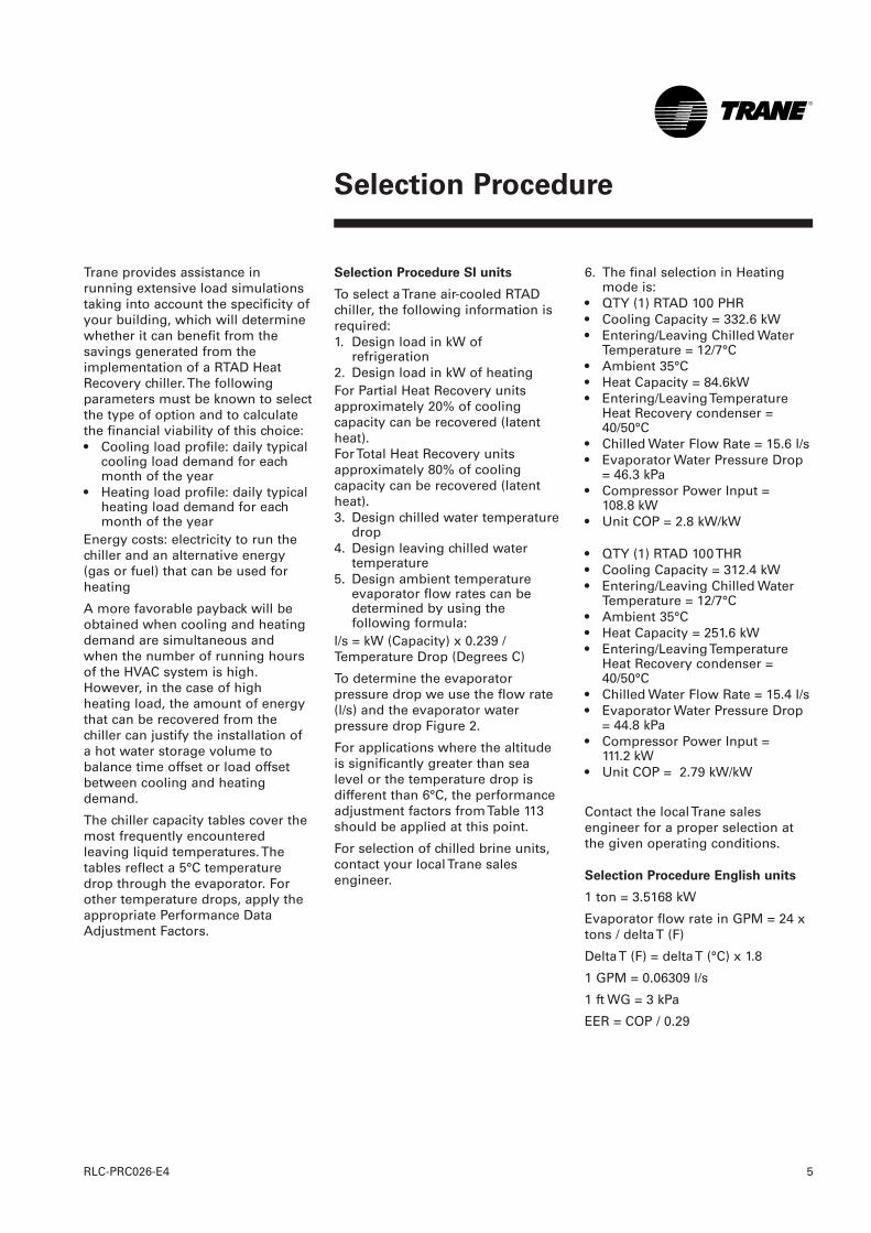
Performance of Heat Recovery units
Heat exchangers are sized torecover up to 80% of the nominalcooling capacity for THR units and25% of the nominal cooling capacityfor PHR units.
Figure 1 - Performance
CC = Cooling capacityHC = Heating capacity
CC
Partial HeatRecovery
Total HeatRecovery
No
min
al c
oo
ling
cap
acit
y (k
W)
CC HC CC HC
Selection Procedure
5RLC-PRC026-E4
Trane provides assistance inrunning extensive load simulationstaking into account the specificity ofyour building, which will determinewhether it can benefit from thesavings generated from theimplementation of a RTAD HeatRecovery chiller. The followingparameters must be known to selectthe type of option and to calculatethe financial viability of this choice:• Cooling load profile: daily typical
cooling load demand for eachmonth of the year
• Heating load profile: daily typicalheating load demand for eachmonth of the year
Energy costs: electricity to run thechiller and an alternative energy(gas or fuel) that can be used forheating
A more favorable payback will beobtained when cooling and heatingdemand are simultaneous andwhen the number of running hoursof the HVAC system is high.However, in the case of highheating load, the amount of energythat can be recovered from thechiller can justify the installation ofa hot water storage volume tobalance time offset or load offsetbetween cooling and heatingdemand.
The chiller capacity tables cover themost frequently encounteredleaving liquid temperatures. Thetables reflect a 5°C temperaturedrop through the evaporator. Forother temperature drops, apply theappropriate Performance DataAdjustment Factors.
Selection Procedure SI units
To select a Trane air-cooled RTADchiller, the following information isrequired:1. Design load in kW of
refrigeration2. Design load in kW of heatingFor Partial Heat Recovery unitsapproximately 20% of coolingcapacity can be recovered (latentheat).For Total Heat Recovery unitsapproximately 80% of coolingcapacity can be recovered (latentheat).3. Design chilled water temperature
drop4. Design leaving chilled water
temperature5. Design ambient temperature
evaporator flow rates can bedetermined by using thefollowing formula:
l/s = kW (Capacity) x 0.239 /Temperature Drop (Degrees C)
To determine the evaporatorpressure drop we use the flow rate(l/s) and the evaporator waterpressure drop Figure 2.
For applications where the altitudeis significantly greater than sealevel or the temperature drop isdifferent than 6°C, the performanceadjustment factors from Table 113should be applied at this point.
For selection of chilled brine units,contact your local Trane salesengineer.
6. The final selection in Heatingmode is:
• QTY (1) RTAD 100 PHR• Cooling Capacity = 332.6 kW• Entering/Leaving Chilled Water
Temperature = 12/7°C• Ambient 35°C• Heat Capacity = 84.6kW• Entering/Leaving Temperature
Heat Recovery condenser =40/50°C
• Chilled Water Flow Rate = 15.6 l/s• Evaporator Water Pressure Drop
= 46.3 kPa• Compressor Power Input =
108.8 kW• Unit COP = 2.8 kW/kW
• QTY (1) RTAD 100 THR• Cooling Capacity = 312.4 kW• Entering/Leaving Chilled Water
Temperature = 12/7°C• Ambient 35°C• Heat Capacity = 251.6 kW• Entering/Leaving Temperature
Heat Recovery condenser =40/50°C
• Chilled Water Flow Rate = 15.4 l/s• Evaporator Water Pressure Drop
= 44.8 kPa• Compressor Power Input =
111.2 kW• Unit COP = 2.79 kW/kW
Contact the local Trane salesengineer for a proper selection atthe given operating conditions.
Selection Procedure English units
1 ton = 3.5168 kW
Evaporator flow rate in GPM = 24 xtons / delta T (F)
Delta T (F) = delta T (°C) x 1.8
1 GPM = 0.06309 l/s
1 ft WG = 3 kPa
EER = COP / 0.29
General Data
RLC-PRC026-E46
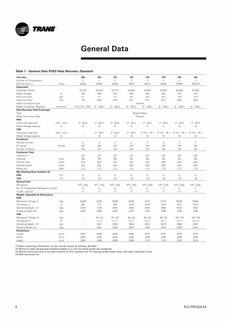
Table 1 - General Data RTAD Heat Recovery Standard
Unit Size 085 100 115 125 145 150 165 180
Number of Compressors 2 2 2 2 2 2 2 2Nominal Size (1) (Tons) 40/40 50/50 60/60 70/70 85/70 85/85 100/85 100/100Evaporator
Evaporator Model EG120 EG140 EG170 EG200 EG200 EG200 EG250 EG250Water Storage (l) 106 269 223 204 204 204 415 415Minimum Flow (l/s) 4.1 6 7.3 8.8 8.8 8.8 11.6 11.6Maximum Flow (l/s) 17.3 20.8 24.8 30.7 30.7 30.7 38.0 38.0Water Connection Type VictaulicWater Connection Diameter (inch-mm) 5"1/2 O.D.- 139.7 6" - 168.3 6" - 168.3 6" - 168.3 6" - 168.3 6" - 168.3 6" - 168.3 6" - 168.3Heat Recovery Heat-Exchanger
Type Brazed PlatesWater Connection Type VictaulicPHR
Connection diameter (inch - mm) 2" - 60.3 2" - 60.3 2" - 60.3 2" - 60.3 2" - 60.3 2" - 60.3 2" - 60.3 2" - 60.3Water Storage capacity (l) 8 8 9 9 11 11 12 12THR
Connection diameter (inch - mm) - 2" - 60.3 2" - 60.3 2" - 60.3 3" O.D. - 76.1 3" O.D. - 76.1 3" O.D. - 76.1 3" O.D. - 76.1Water Storage capacity (l) - 10 14 14 16 16 19 19Condenser
Number of Coils 2 2 2 2 2 2 2 2Fin series (Fins/ft) 192 192 192 192 192 192 192 192Number of Rows 3/3 2/2 3/3 3/3 3/3 3/3 3/3 3/3Condenser Fans
Quantity (1) 3/3 3/3 3/3 3/3 5/4 5/5 6/5 6/6Diameter (mm) 762 762 762 762 762 762 762 762Total Air Flow (m3/s) 23.4 28.5 27.0 27.0 37.0 39.0 44.9 46.8Nominal Speed (rpm) 930 930 930 930 930 930 930 930Motor kW (kW) 1.72 1.72 1.72 1.72 1.72 1.72 1.72 1.72Min Starting/Oper Ambient (2)
PHR (°C) 0 0 0 0 0 0 0 0THR (°C) -18 -18 -18 -18 -18 -18 -18 -18General Unit
Refrigerant HFC 134a HFC 134a HFC 134a HFC 134a HFC 134a HFC 134a HFC 134a HFC 134a No. Of independent Refrigerant Circuits 2 2 2 2 2 2 2 2% Min. Load (3) 17 17 17 17 17 17 17 17Weight. Capacities & Dimensions
PHR
Refrigerant Charge (1) (kg) 26/26 33/35 38/39 39/40 47/51 47/51 65/63 65/65Oil Charge (1) (l) 6/6 7/7 9/9 10/10 10/10 10/10 15/11 15/15Operating Weight (4) (kg) 2736 3176 3635 3650 4345 4605 5535 5622Shipping Weight (4) (kg) 2622 2899 3403 3437 4130 4390 5108 5195THR
Refrigerant Charge (1) (kg) - 55 / 52 67 / 64 68 / 64 86 / 84 86 / 84 100 / 95 100 / 98Oil Charge (1) (l) - 5 / 4 8 / 7 8 / 7 8 / 7 8 / 7 13 / 7 13 / 12Operating Weight (4) (kg) - 3347 3833 3848 4615 4875 5806 5891Shipping Weight (4) (kg) - 3061 3589 3623 4382 4642 5359 5444Dimensions
Length (mm) 3507 4426 4426 4426 5351 5351 6370 6370Width (mm) 2260 2260 2260 2260 2260 2260 2260 2260Height (mm) 2095 2095 2095 2095 2115 2115 2215 2215
(1) Data containing information on two circuits shown as follows: ckt1/ckt2(2) Minimum start-up/operation ambient based on a 2.22 m/s wind across the condenser.(3) Percent minimum load is for total machine at 10°C ambient and 7°C leaving chilled water temp. Not each individual circuit.(4) With aluminum fin
General Data
7RLC-PRC026-E4
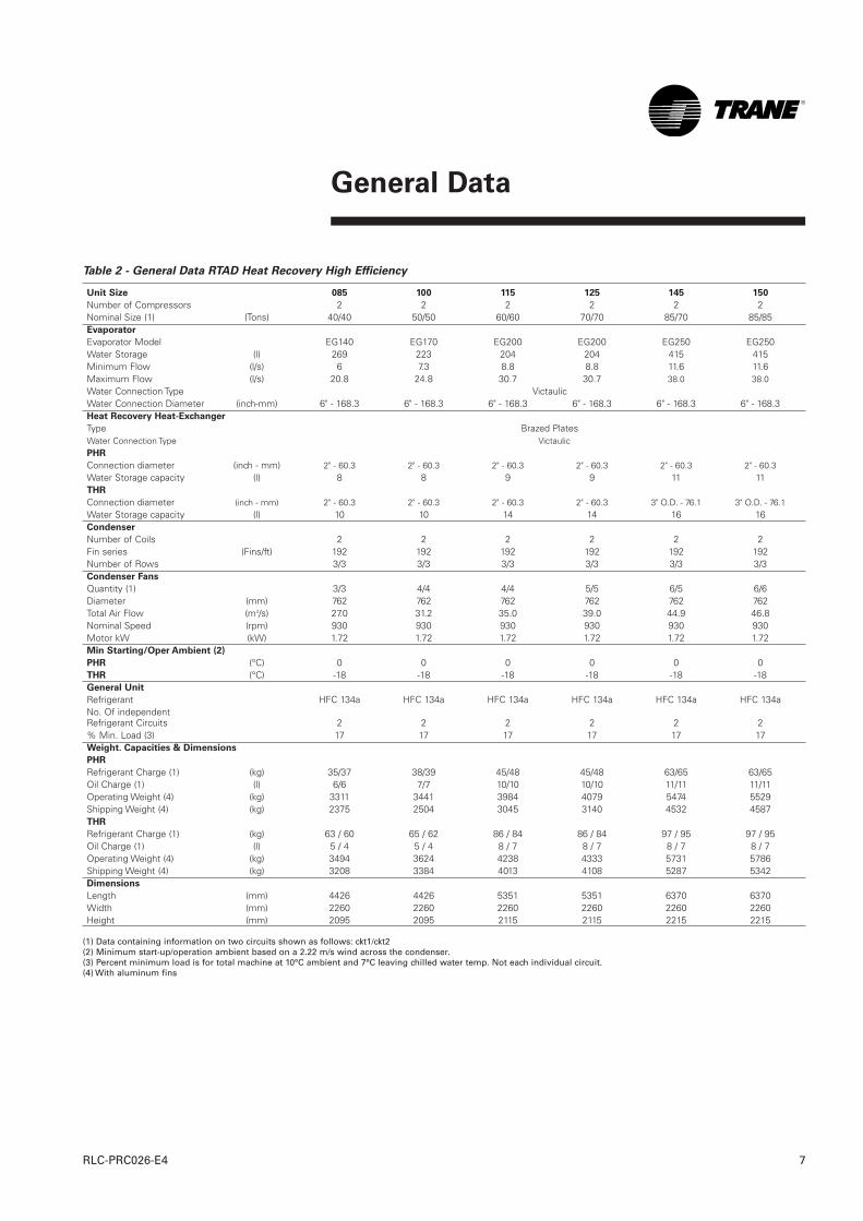
Table 2 - General Data RTAD Heat Recovery High Efficiency
Unit Size 085 100 115 125 145 150
Number of Compressors 2 2 2 2 2 2Nominal Size (1) (Tons) 40/40 50/50 60/60 70/70 85/70 85/85 Evaporator
Evaporator Model EG140 EG170 EG200 EG200 EG250 EG250Water Storage (l) 269 223 204 204 415 415Minimum Flow (l/s) 6 7.3 8.8 8.8 11.6 11.6Maximum Flow (l/s) 20.8 24.8 30.7 30.7 38.0 38.0Water Connection Type VictaulicWater Connection Diameter (inch-mm) 6" - 168.3 6" - 168.3 6" - 168.3 6" - 168.3 6" - 168.3 6" - 168.3Heat Recovery Heat-Exchanger
Type Brazed PlatesWater Connection Type VictaulicPHR
Connection diameter (inch - mm) 2" - 60.3 2" - 60.3 2" - 60.3 2" - 60.3 2" - 60.3 2" - 60.3Water Storage capacity (l) 8 8 9 9 11 11THR
Connection diameter (inch - mm) 2" - 60.3 2" - 60.3 2" - 60.3 2" - 60.3 3" O.D. - 76.1 3" O.D. - 76.1Water Storage capacity (l) 10 10 14 14 16 16Condenser
Number of Coils 2 2 2 2 2 2Fin series (Fins/ft) 192 192 192 192 192 192Number of Rows 3/3 3/3 3/3 3/3 3/3 3/3Condenser Fans
Quantity (1) 3/3 4/4 4/4 5/5 6/5 6/6Diameter (mm) 762 762 762 762 762 762Total Air Flow (m3/s) 27.0 31.2 35.0 39.0 44.9 46.8Nominal Speed (rpm) 930 930 930 930 930 930Motor kW (kW) 1.72 1.72 1.72 1.72 1.72 1.72Min Starting/Oper Ambient (2)
PHR (°C) 0 0 0 0 0 0THR (°C) -18 -18 -18 -18 -18 -18General Unit
Refrigerant HFC 134a HFC 134a HFC 134a HFC 134a HFC 134a HFC 134a No. Of independent Refrigerant Circuits 2 2 2 2 2 2% Min. Load (3) 17 17 17 17 17 17Weight. Capacities & Dimensions
PHR
Refrigerant Charge (1) (kg) 35/37 38/39 45/48 45/48 63/65 63/65Oil Charge (1) (l) 6/6 7/7 10/10 10/10 11/11 11/11Operating Weight (4) (kg) 3311 3441 3984 4079 5474 5529Shipping Weight (4) (kg) 2375 2504 3045 3140 4532 4587THR
Refrigerant Charge (1) (kg) 63 / 60 65 / 62 86 / 84 86 / 84 97 / 95 97 / 95Oil Charge (1) (l) 5 / 4 5 / 4 8 / 7 8 / 7 8 / 7 8 / 7Operating Weight (4) (kg) 3494 3624 4238 4333 5731 5786Shipping Weight (4) (kg) 3208 3384 4013 4108 5287 5342Dimensions
Length (mm) 4426 4426 5351 5351 6370 6370Width (mm) 2260 2260 2260 2260 2260 2260Height (mm) 2095 2095 2115 2115 2215 2215
(1) Data containing information on two circuits shown as follows: ckt1/ckt2(2) Minimum start-up/operation ambient based on a 2.22 m/s wind across the condenser.(3) Percent minimum load is for total machine at 10°C ambient and 7°C leaving chilled water temp. Not each individual circuit.(4) With aluminum fins
General Data
RLC-PRC026-E48
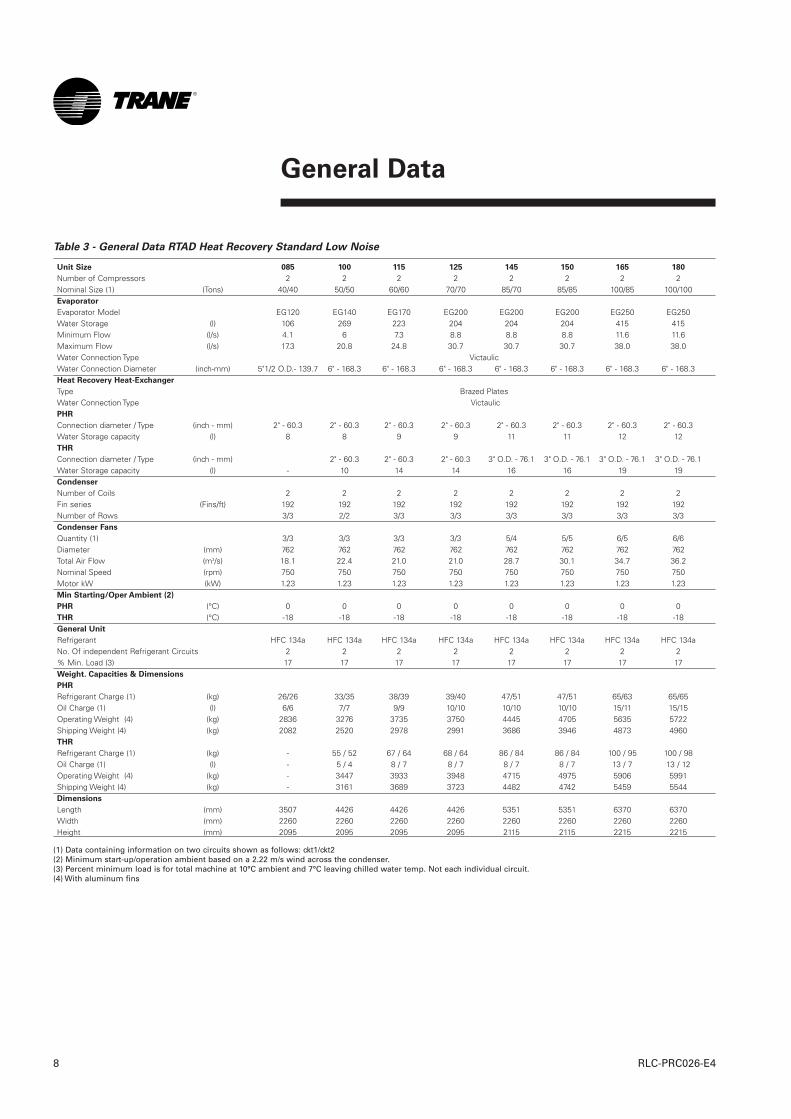
Table 3 - General Data RTAD Heat Recovery Standard Low Noise
Unit Size 085 100 115 125 145 150 165 180
Number of Compressors 2 2 2 2 2 2 2 2Nominal Size (1) (Tons) 40/40 50/50 60/60 70/70 85/70 85/85 100/85 100/100Evaporator
Evaporator Model EG120 EG140 EG170 EG200 EG200 EG200 EG250 EG250Water Storage (l) 106 269 223 204 204 204 415 415Minimum Flow (l/s) 4.1 6 7.3 8.8 8.8 8.8 11.6 11.6Maximum Flow (l/s) 17.3 20.8 24.8 30.7 30.7 30.7 38.0 38.0Water Connection Type VictaulicWater Connection Diameter (inch-mm) 5"1/2 O.D.- 139.7 6" - 168.3 6" - 168.3 6" - 168.3 6" - 168.3 6" - 168.3 6" - 168.3 6" - 168.3Heat Recovery Heat-Exchanger
Type Brazed PlatesWater Connection Type VictaulicPHR
Connection diameter / Type (inch - mm) 2" - 60.3 2" - 60.3 2" - 60.3 2" - 60.3 2" - 60.3 2" - 60.3 2" - 60.3 2" - 60.3Water Storage capacity (l) 8 8 9 9 11 11 12 12THR
Connection diameter / Type (inch - mm) 2" - 60.3 2" - 60.3 2" - 60.3 3" O.D. - 76.1 3" O.D. - 76.1 3" O.D. - 76.1 3" O.D. - 76.1Water Storage capacity (l) - 10 14 14 16 16 19 19Condenser
Number of Coils 2 2 2 2 2 2 2 2Fin series (Fins/ft) 192 192 192 192 192 192 192 192Number of Rows 3/3 2/2 3/3 3/3 3/3 3/3 3/3 3/3Condenser Fans
Quantity (1) 3/3 3/3 3/3 3/3 5/4 5/5 6/5 6/6Diameter (mm) 762 762 762 762 762 762 762 762Total Air Flow (m3/s) 18.1 22.4 21.0 21.0 28.7 30.1 34.7 36.2Nominal Speed (rpm) 750 750 750 750 750 750 750 750Motor kW (kW) 1.23 1.23 1.23 1.23 1.23 1.23 1.23 1.23Min Starting/Oper Ambient (2)
PHR (°C) 0 0 0 0 0 0 0 0THR (°C) -18 -18 -18 -18 -18 -18 -18 -18General Unit
Refrigerant HFC 134a HFC 134a HFC 134a HFC 134a HFC 134a HFC 134a HFC 134a HFC 134a No. Of independent Refrigerant Circuits 2 2 2 2 2 2 2 2% Min. Load (3) 17 17 17 17 17 17 17 17Weight. Capacities & Dimensions
PHR
Refrigerant Charge (1) (kg) 26/26 33/35 38/39 39/40 47/51 47/51 65/63 65/65Oil Charge (1) (l) 6/6 7/7 9/9 10/10 10/10 10/10 15/11 15/15Operating Weight (4) (kg) 2836 3276 3735 3750 4445 4705 5635 5722Shipping Weight (4) (kg) 2082 2520 2978 2991 3686 3946 4873 4960THR
Refrigerant Charge (1) (kg) - 55 / 52 67 / 64 68 / 64 86 / 84 86 / 84 100 / 95 100 / 98Oil Charge (1) (l) - 5 / 4 8 / 7 8 / 7 8 / 7 8 / 7 13 / 7 13 / 12Operating Weight (4) (kg) - 3447 3933 3948 4715 4975 5906 5991Shipping Weight (4) (kg) - 3161 3689 3723 4482 4742 5459 5544Dimensions
Length (mm) 3507 4426 4426 4426 5351 5351 6370 6370Width (mm) 2260 2260 2260 2260 2260 2260 2260 2260Height (mm) 2095 2095 2095 2095 2115 2115 2215 2215
(1) Data containing information on two circuits shown as follows: ckt1/ckt2(2) Minimum start-up/operation ambient based on a 2.22 m/s wind across the condenser.(3) Percent minimum load is for total machine at 10°C ambient and 7°C leaving chilled water temp. Not each individual circuit.(4) With aluminum fins

General Data
9RLC-PRC026-E4
Table 4 - General Data RTAD Heat Recovery High Efficiency Low Noise
Unit Size 085 100 115 125 145 150
Number of Compressors 2 2 2 2 2 2Nominal Size (1) (Tons) 40/40 50/50 60/60 70/70 85/70 85/85 Evaporator
Evaporator Model EG140 EG170 EG200 EG200 EG250 EG250Water Storage (l) 269 223 204 204 415 415Minimum Flow (l/s) 6 7.3 8.8 8.8 11.6 11.6Maximum Flow l/s) 20.8 24.8 30.7 30.7 38.0 38.0Water Connection Type VictaulicWater Connection Diameter (inch-mm) 6" - 168.3 6" - 168.3 6" - 168.3 6" - 168.3 6" - 168.3 6" - 168.3Heat Recovery Heat-Exchanger
Type Brazed PlatesWater Connection Type VictaulicPHR
Connection diameter (inch - mm) 2" - 60.3 2" - 60.3 2" - 60.3 2" - 60.3 2" - 60.3 2" - 60.3Water Storage capacity (l) 8 8 9 9 11 11THR
Connection diameter (inch - mm) 2" - 60.3 2" - 60.3 2" - 60.3 2" - 60.3 3" O.D. - 76.1 3" O.D. - 76.1Water Storage capacity (l) 10 10 14 14 16 16Condenser
Number of Coils 2 2 2 2 2 2Fin series (Fins/ft) 192 192 192 192 192 192Number of Rows 3/3 3/3 3/3 3/3 3/3 3/3Condenser Fans
Quantity (1) 3/3 4/4 4/4 5/5 6/5 6/6Diameter (mm) 762 762 762 762 762 762Total Air Flow (m3/s) 21.0 24.1 27.2 30.1 34.7 36.2Nominal Speed (rpm) 750 750 750 750 750 750Motor kW (kW) 1.23 1.23 1.23 1.23 1.23 1.23Min Starting/Oper Ambient (2)
PHR (°C) 0 0 0 0 0 0THR (°C) -18 -18 -18 -18 -18 -18General Unit
Refrigerant HFC 134a HFC 134a HFC 134a HFC 134a HFC 134a HFC 134a No. Of independent Refrigerant Circuits 2 2 2 2 2 2% Min. Load (3) 17 17 17 17 17 17Weight. Capacities & Dimensions
PHR
Refrigerant Charge (1) (kg) 35/37 38/39 45/48 45/48 63/65 63/65Oil Charge (1) (l) 6/6 7/7 10/10 10/10 11/11 11/11Operating Weight (4) (kg) 3411 3541 4084 4179 5574 5629Shipping Weight (4) (kg) 2655 2784 3325 3420 4812 4867THR
Refrigerant Charge (1) (kg) 63 / 60 65 / 62 86 / 84 86 / 84 97 / 95 97 / 95Oil Charge (1) (l) 5 / 4 5 / 4 8 / 7 8 / 7 8 / 7 8 / 7Operating Weight (4) (kg) 3594 3724 4338 4433 5831 5886Shipping Weight (4) (kg) 3308 3484 4113 4208 5387 5442Dimensions
Length (mm) 4426 4426 5351 5351 6370 6370Width (mm) 2260 2260 2260 2260 2260 2260Height (mm) 2095 2095 2115 2115 2215 2215
(1) Data containing information on two circuits shown as follows: ckt1/ckt2(2) Minimum start-up/operation ambient based on a 2.22 m/s wind across the condenser.(3) Percent minimum load is for total machine at 10°C ambient and 7°C leaving chilled water temp. Not each individual circuit.(4) With aluminum fins
Performance Data - Partial Heat Recovery
RLC-PRC026-E410
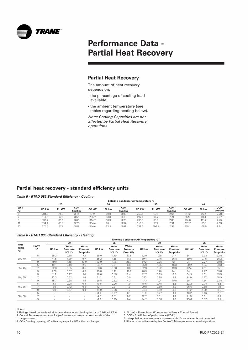
Partial Heat Recovery
The amount of heat recoverydepends on:
- the percentage of cooling loadavailable
- the ambient temperature (seetables regarding heating below).
Note: Cooling Capacities are notaffected by Partial Heat Recoveryoperations.
Table 5 - RTAD 085 Standard Efficiency - Cooling
Entering Condenser Air Temperature °C
25 30 35 40
5 294.3 74.8 3.44 277.4 80.8 3.03 259.5 87.6 2.64 241.2 95.2 2.287 313.6 77.6 3.55 295.7 83.8 3.13 277.1 90.7 2.74 257.7 98.4 2.379 333.7 80.6 3.65 314.7 86.9 3.23 295.0 93.9 2.83 274.6 101.7 2.4511 354.4 83.8 3.75 334.4 90.1 3.32 313.6 97.2 2.91 292.2 105.1 2.5313 375.5 87.1 3.84 354.4 93.5 3.41 332.6 100.7 2.99 310.1 108.6 2.61
Table 6 - RTAD 085 Standard Efficiency - Heating
Entering Condenser Air Temperature °C
20 25 30 35
5 35.2 0.85 7.3 58.0 1.40 17.3 82.0 1.98 31.4 84.1 2.03 32.830 / 40 7 41.5 1.00 9.7 65.2 1.58 21.2 89.4 2.16 36.5 89.0 2.15 36.2
9 49.0 1.18 13.0 72.9 1.76 25.7 97.2 2.35 42.1 94.1 2.27 39.85 19.1 0.46 2.6 33.7 0.81 6.8 55.9 1.35 16.3 80.2 1.94 30.3
35 / 45 7 22.8 0.55 3.5 38.6 0.93 8.6 62.9 1.52 19.9 87.4 2.11 35.19 27.8 0.67 4.9 45.8 1.11 11.6 70.3 1.70 24.1 94.1 2.27 39.85 11.2 0.27 1.0 18.6 0.45 2.4 32.7 0.79 6.5 54.3 1.31 15.5
40 / 50 7 13.3 0.32 1.4 21.1 0.51 3.0 37.3 0.90 8.1 61.0 1.47 18.99 15.7 0.38 1.8 25.8 0.62 4.3 43.3 1.04 10.5 68.1 1.64 22.85 3.4 0.08 0.1 10.8 0.26 1.0 18.6 0.45 2.5 32.2 0.78 6.3
45 / 55 7 5.0 0.12 0.3 12.7 0.31 1.3 20.8 0.50 3.0 36.5 0.88 7.89 6.9 0.17 0.4 14.9 0.36 1.7 24.4 0.59 3.9 41.2 1.00 9.65 - - - 3.1 0.07 0.1 11.0 0.27 1.0 19.2 0.46 2.6
50 / 60 7 - - - 4.5 0.11 0.2 12.7 0.31 1.3 21.3 0.51 3.19 - - - 6.2 0.15 0.4 14.7 0.36 1.6 23.6 0.57 3.7
LWT
°CCC kW P.I. kW
COP
kW/kWCC kW P.I. kW
COP
kW/kWCC kW P.I. kW
COP
kW/kWCC kW P.I. kW
COP
kW/kW
PHR
Temp
°C
LWTE
°C HC kW
Water
flow rate
HX l/s
Water
Pressure
Drop kPa
HC kW
Water
flow rate
HX l/s
Water
Pressure
Drop kPa
HC kW
Water
flow rate
HX l/s
Water
Pressure
Drop kPa
HC kW
Water
flow rate
HX l/s
Water
Pressure
Drop kPa
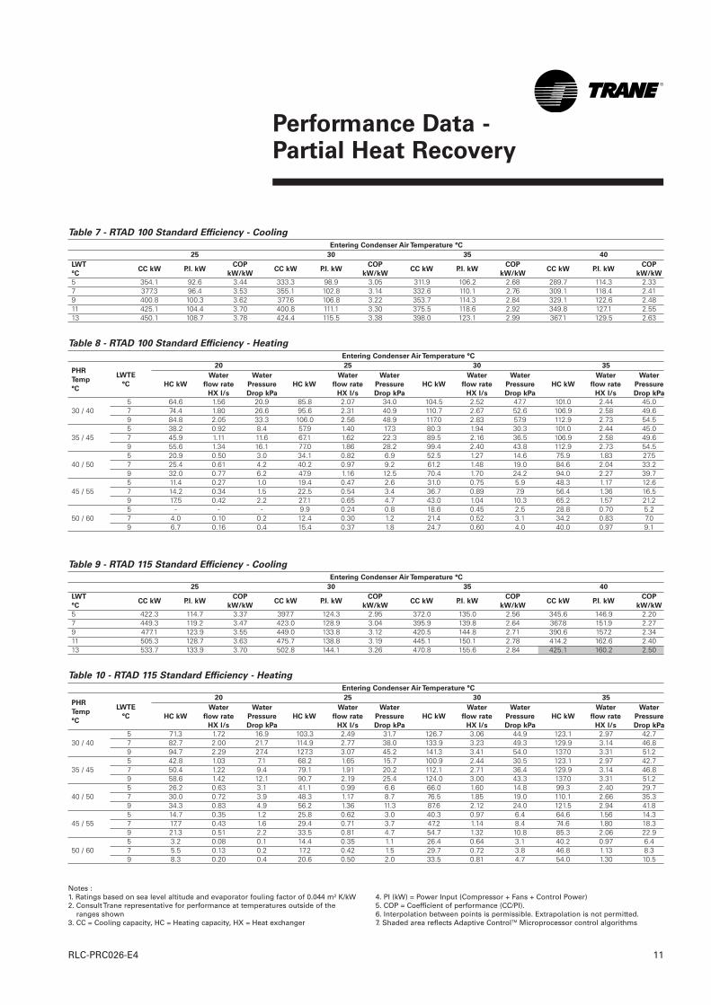
Partial heat recovery - standard efficiency units
Notes :1. Ratings based on sea level altitude and evaporator fouling factor of 0.044 m² K/kW2. Consult Trane representative for performance at temperatures outside of the
ranges shown3. CC = Cooling capacity, HC = Heating capacity, HX = Heat exchanger
4. PI (kW) = Power Input (Compressor + Fans + Control Power)5. COP = Coefficient of performance (CC/PI).6. Interpolation between points is permissible. Extrapolation is not permitted.7. Shaded area reflects Adaptive ControlTM Microprocessor control algorithms
Performance Data - Partial Heat Recovery
11RLC-PRC026-E4
Notes :1. Ratings based on sea level altitude and evaporator fouling factor of 0.044 m² K/kW2. Consult Trane representative for performance at temperatures outside of the
ranges shown3. CC = Cooling capacity, HC = Heating capacity, HX = Heat exchanger
4. PI (kW) = Power Input (Compressor + Fans + Control Power)5. COP = Coefficient of performance (CC/PI).6. Interpolation between points is permissible. Extrapolation is not permitted.7. Shaded area reflects Adaptive ControlTM Microprocessor control algorithms
Table 7 - RTAD 100 Standard Efficiency - Cooling
Entering Condenser Air Temperature °C
25 30 35 40
5 354.1 92.6 3.44 333.3 98.9 3.05 311.9 106.2 2.68 289.7 114.3 2.337 377.3 96.4 3.53 355.1 102.8 3.14 332.6 110.1 2.76 309.1 118.4 2.419 400.8 100.3 3.62 377.6 106.8 3.22 353.7 114.3 2.84 329.1 122.6 2.4811 425.1 104.4 3.70 400.8 111.1 3.30 375.5 118.6 2.92 349.8 127.1 2.5513 450.1 108.7 3.78 424.4 115.5 3.38 398.0 123.1 2.99 367.1 129.5 2.63
Table 8 - RTAD 100 Standard Efficiency - Heating
Entering Condenser Air Temperature °C
20 25 30 35
5 64.6 1.56 20.9 85.8 2.07 34.0 104.5 2.52 47.7 101.0 2.44 45.030 / 40 7 74.4 1.80 26.6 95.6 2.31 40.9 110.7 2.67 52.6 106.9 2.58 49.6
9 84.8 2.05 33.3 106.0 2.56 48.9 117.0 2.83 57.9 112.9 2.73 54.55 38.2 0.92 8.4 57.9 1.40 17.3 80.3 1.94 30.3 101.0 2.44 45.0
35 / 45 7 45.9 1.11 11.6 67.1 1.62 22.3 89.5 2.16 36.5 106.9 2.58 49.69 55.6 1.34 16.1 77.0 1.86 28.2 99.4 2.40 43.8 112.9 2.73 54.55 20.9 0.50 3.0 34.1 0.82 6.9 52.5 1.27 14.6 75.9 1.83 27.5
40 / 50 7 25.4 0.61 4.2 40.2 0.97 9.2 61.2 1.48 19.0 84.6 2.04 33.29 32.0 0.77 6.2 47.9 1.16 12.5 70.4 1.70 24.2 94.0 2.27 39.75 11.4 0.27 1.0 19.4 0.47 2.6 31.0 0.75 5.9 48.3 1.17 12.6
45 / 55 7 14.2 0.34 1.5 22.5 0.54 3.4 36.7 0.89 7.9 56.4 1.36 16.59 17.5 0.42 2.2 27.1 0.65 4.7 43.0 1.04 10.3 65.2 1.57 21.25 - - - 9.9 0.24 0.8 18.6 0.45 2.5 28.8 0.70 5.2
50 / 60 7 4.0 0.10 0.2 12.4 0.30 1.2 21.4 0.52 3.1 34.2 0.83 7.09 6.7 0.16 0.4 15.4 0.37 1.8 24.7 0.60 4.0 40.0 0.97 9.1
LWT
°CCC kW P.I. kW
COP
kW/kWCC kW P.I. kW
COP
kW/kWCC kW P.I. kW
COP
kW/kWCC kW P.I. kW
COP
kW/kW
PHR
Temp
°C
LWTE
°C HC kW
Water
flow rate
HX l/s
Water
Pressure
Drop kPa
HC kW
Water
flow rate
HX l/s
Water
Pressure
Drop kPa
HC kW
Water
flow rate
HX l/s
Water
Pressure
Drop kPa
HC kW
Water
flow rate
HX l/s
Water
Pressure
Drop kPa
Table 9 - RTAD 115 Standard Efficiency - Cooling
Entering Condenser Air Temperature °C
25 30 35 40
5 422.3 114.7 3.37 397.7 124.3 2.95 372.0 135.0 2.56 345.6 146.9 2.207 449.3 119.2 3.47 423.0 128.9 3.04 395.9 139.8 2.64 367.8 151.9 2.279 477.1 123.9 3.55 449.0 133.8 3.12 420.5 144.8 2.71 390.6 157.2 2.3411 505.3 128.7 3.63 475.7 138.8 3.19 445.1 150.1 2.78 414.2 162.6 2.4013 533.7 133.9 3.70 502.8 144.1 3.26 470.8 155.6 2.84 425.1 160.2 2.50
Table 10 - RTAD 115 Standard Efficiency - Heating
Entering Condenser Air Temperature °C
20 25 30 35
5 71.3 1.72 16.9 103.3 2.49 31.7 126.7 3.06 44.9 123.1 2.97 42.730 / 40 7 82.7 2.00 21.7 114.9 2.77 38.0 133.9 3.23 49.3 129.9 3.14 46.8
9 94.7 2.29 27.4 127.3 3.07 45.2 141.3 3.41 54.0 137.0 3.31 51.25 42.8 1.03 7.1 68.2 1.65 15.7 100.9 2.44 30.5 123.1 2.97 42.7
35 / 45 7 50.4 1.22 9.4 79.1 1.91 20.2 112.1 2.71 36.4 129.9 3.14 46.89 58.6 1.42 12.1 90.7 2.19 25.4 124.0 3.00 43.3 137.0 3.31 51.25 26.2 0.63 3.1 41.1 0.99 6.6 66.0 1.60 14.8 99.3 2.40 29.7
40 / 50 7 30.0 0.72 3.9 48.3 1.17 8.7 76.5 1.85 19.0 110.1 2.66 35.39 34.3 0.83 4.9 56.2 1.36 11.3 87.6 2.12 24.0 121.5 2.94 41.85 14.7 0.35 1.2 25.8 0.62 3.0 40.3 0.97 6.4 64.6 1.56 14.3
45 / 55 7 17.7 0.43 1.6 29.4 0.71 3.7 47.2 1.14 8.4 74.6 1.80 18.39 21.3 0.51 2.2 33.5 0.81 4.7 54.7 1.32 10.8 85.3 2.06 22.95 3.2 0.08 0.1 14.4 0.35 1.1 26.4 0.64 3.1 40.2 0.97 6.4
50 / 60 7 5.5 0.13 0.2 17.2 0.42 1.5 29.7 0.72 3.8 46.8 1.13 8.39 8.3 0.20 0.4 20.6 0.50 2.0 33.5 0.81 4.7 54.0 1.30 10.5
LWT
°CCC kW P.I. kW
COP
kW/kWCC kW P.I. kW
COP
kW/kWCC kW P.I. kW
COP
kW/kWCC kW P.I. kW
COP
kW/kW
PHR
Temp
°C
LWTE
°C HC kW
Water
flow rate
HX l/s
Water
Pressure
Drop kPa
HC kW
Water
flow rate
HX l/s
Water
Pressure
Drop kPa
HC kW
Water
flow rate
HX l/s
Water
Pressure
Drop kPa
HC kW
Water
flow rate
HX l/s
Water
Pressure
Drop kPa
Performance Data - Partial Heat Recovery
RLC-PRC026-E412
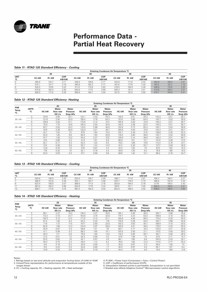
Table 13 - RTAD 145 Standard Efficiency - Cooling
Entering Condenser Air Temperature °C
25 30 35 40
5 550.6 146.9 3.39 520.0 158.7 2.99 488.7 171.8 2.61 456.4 186.4 2.277 586.5 152.8 3.48 554.1 164.7 3.08 520.7 178.0 2.70 486.6 192.8 2.349 623.4 158.9 3.57 588.9 171.0 3.16 553.8 184.5 2.78 517.6 199.4 2.4211 661.0 165.2 3.66 624.8 177.5 3.24 587.5 191.1 2.85 532.3 197.0 2.5113 699.7 171.8 3.74 661.4 184.2 3.32 622.0 198.0 2.92 538.0 189.5 2.63
Table 14 - RTAD 145 Standard Efficiency - Heating
Entering Condenser Air Temperature °C
20 25 30 35
5 98.1 2.37 19.2 139.3 3.37 35.6 165.1 3.99 48.0 160.7 3.88 45.830 / 40 7 113.2 2.73 24.7 154.6 3.74 42.8 174.7 4.22 53.0 169.9 4.10 50.5
9 129.3 3.12 31.2 171.0 4.13 51.1 184.6 4.46 58.4 179.2 4.33 55.55 61.4 1.48 8.4 93.3 2.25 17.6 135.6 3.28 34.0 160.7 3.88 45.8
35 / 45 7 71.6 1.73 11.0 107.7 2.60 22.6 150.3 3.63 40.7 169.9 4.10 50.59 82.6 1.99 14.2 123.0 2.97 28.6 165.9 4.01 48.5 179.2 4.33 55.55 35.9 0.87 3.3 58.6 1.41 7.8 89.7 2.17 16.4 133.0 3.21 32.9
40 / 50 7 41.1 0.99 4.2 68.2 1.65 10.1 103.5 2.50 21.1 147.2 3.55 39.29 50.3 1.21 5.9 78.6 1.90 13.0 118.2 2.85 26.7 162.1 3.92 46.55 21.2 0.51 1.3 35.3 0.85 3.2 57.0 1.38 7.4 87.3 2.11 15.7
45 / 55 7 25.5 0.62 1.8 40.1 0.97 4.0 66.1 1.60 9.6 100.5 2.43 20.19 30.4 0.73 2.4 46.5 1.12 5.2 76.0 1.84 12.3 114.5 2.77 25.25 6.6 0.16 0.2 20.8 0.50 1.3 35.9 0.87 3.3 56.4 1.36 7.3
50 / 60 7 9.9 0.24 0.3 24.6 0.60 1.7 40.3 0.97 4.0 65.1 1.57 9.49 13.8 0.33 0.6 29.1 0.70 2.3 45.4 1.10 5.0 74.5 1.80 11.8
LWT
°CCC kW P.I. kW
COP
kW/kWCC kW P.I. kW
COP
kW/kWCC kW P.I. kW
COP
kW/kWCC kW P.I. kW
COP
kW/kW
PHR
Temp
°C
LWTE
°C HC kW
Water
flow rate
HX l/s
Water
Pressure
Drop kPa
HC kW
Water
flow rate
HX l/s
Water
Pressure
Drop kPa
HC kW
Water
flow rate
HX l/s
Water
Pressure
Drop kPa
HC kW
Water
flow rate
HX l/s
Water
Pressure
Drop kPa
Table 11 - RTAD 125 Standard Efficiency - Cooling
Entering Condenser Air Temperature °C
25 30 35 40
5 485.6 145.7 3.11 456.0 158.0 2.71 425.8 171.6 2.34 394.9 186.5 2.017 515.1 151.7 3.18 483.8 164.2 2.77 451.8 177.9 2.40 401.5 181.2 2.109 545.0 157.8 3.24 511.9 170.6 2.83 478.5 184.6 2.46 406.8 174.8 2.2011 575.6 164.3 3.30 540.8 177.2 2.89 505.3 191.4 2.51 413.8 169.2 2.3113 606.5 171.0 3.35 569.9 184.1 2.94 521.8 191.0 2.60 419.1 164.0 2.41
Table 12 - RTAD 125 Standard Efficiency- Heating
Entering Condenser Air Temperature °C
20 25 30 35
5 107.8 2.60 34.1 142.1 3.43 54.5 149.3 3.61 59.3 145.3 3.51 56.730 / 40 7 121.8 2.94 42.0 156.4 3.78 64.2 157.4 3.80 64.9 145.7 3.52 56.9
9 136.8 3.30 51.1 170.6 4.12 74.4 165.8 4.00 70.9 145.4 3.51 56.75 70.6 1.70 16.6 105.0 2.54 32.6 140.0 3.38 53.2 145.3 3.51 56.7
35 / 45 7 83.7 2.02 22.2 118.5 2.86 40.0 153.8 3.72 62.4 145.7 3.52 56.99 97.8 2.36 28.9 132.9 3.21 48.7 165.8 4.00 70.9 145.4 3.51 56.75 43.1 1.04 7.2 67.9 1.64 15.5 103.1 2.49 31.6 138.6 3.35 52.3
40 / 50 7 52.0 1.26 9.9 80.5 1.94 20.8 116.0 2.80 38.6 145.7 3.52 56.99 61.7 1.49 13.2 94.0 2.27 27.0 129.9 3.14 46.8 145.4 3.51 56.75 27.4 0.66 3.3 41.9 1.01 6.9 66.8 1.61 15.1 101.9 2.46 31.0
45 / 55 7 32.1 0.77 4.3 50.4 1.22 9.4 78.2 1.89 19.8 114.4 2.76 37.79 37.4 0.90 5.6 59.7 1.44 12.5 91.2 2.20 25.7 127.7 3.09 45.55 13.8 0.33 1.0 27.8 0.67 3.4 42.4 1.02 7.0 67.2 1.62 15.3
50 / 60 7 17.6 0.42 1.6 32.1 0.78 4.4 49.8 1.20 9.2 76.8 1.86 19.29 22.0 0.53 2.3 37.1 0.90 5.6 58.6 1.42 12.1 89.2 2.16 24.7
LWT
°CCC kW P.I. kW
COP
kW/kWCC kW P.I. kW
COP
kW/kWCC kW P.I. kW
COP
kW/kWCC kW P.I. kW
COP
kW/kW
PHR
Temp
°C
LWTE
°C HC kW
Water
flow rate
HX l/s
Water
Pressure
Drop kPa
HC kW
Water
flow rate
HX l/s
Water
Pressure
Drop kPa
HC kW
Water
flow rate
HX l/s
Water
Pressure
Drop kPa
HC kW
Water
flow rate
HX l/s
Water
Pressure
Drop kPa
Notes :1. Ratings based on sea level altitude and evaporator fouling factor of 0.044 m² K/kW2. Consult Trane representative for performance at temperatures outside of the
ranges shown3. CC = Cooling capacity, HC = Heating capacity, HX = Heat exchanger
4. PI (kW) = Power Input (Compressor + Fans + Control Power)5. COP = Coefficient of performance (CC/PI).6. Interpolation between points is permissible. Extrapolation is not permitted.7. Shaded area reflects Adaptive ControlTM Microprocessor control algorithms
Performance Data - Partial Heat Recovery
13RLC-PRC026-E4
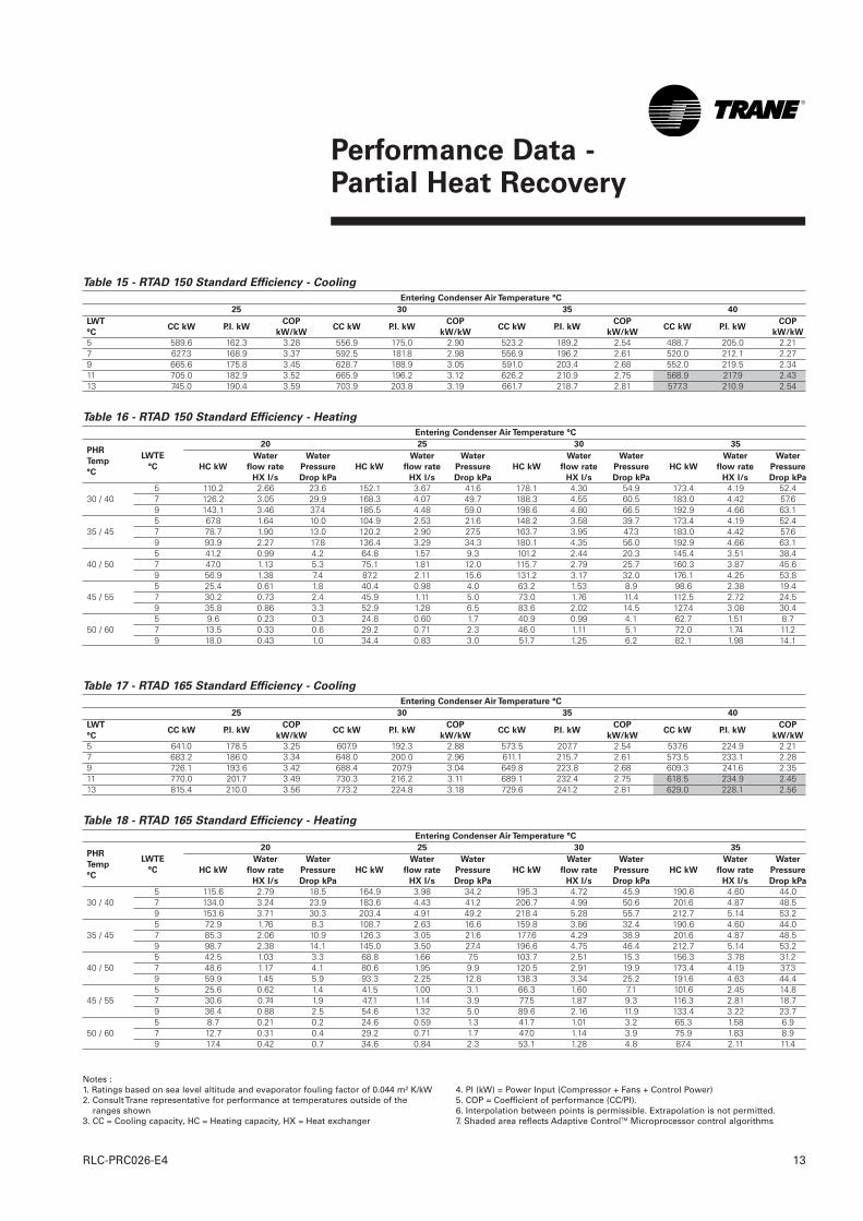
Table 15 - RTAD 150 Standard Efficiency - Cooling
Entering Condenser Air Temperature °C
25 30 35 40
5 589.6 162.3 3.28 556.9 175.0 2.90 523.2 189.2 2.54 488.7 205.0 2.217 627.3 168.9 3.37 592.5 181.8 2.98 556.9 196.2 2.61 520.0 212.1 2.279 665.6 175.8 3.45 628.7 188.9 3.05 591.0 203.4 2.68 552.0 219.5 2.3411 705.0 182.9 3.52 665.9 196.2 3.12 626.2 210.9 2.75 568.9 217.9 2.4313 745.0 190.4 3.59 703.9 203.8 3.19 661.7 218.7 2.81 577.3 210.9 2.54
Table 16 - RTAD 150 Standard Efficiency - Heating
Entering Condenser Air Temperature °C
20 25 30 35
5 110.2 2.66 23.6 152.1 3.67 41.6 178.1 4.30 54.9 173.4 4.19 52.430 / 40 7 126.2 3.05 29.9 168.3 4.07 49.7 188.3 4.55 60.5 183.0 4.42 57.6
9 143.1 3.46 37.4 185.5 4.48 59.0 198.6 4.80 66.5 192.9 4.66 63.15 67.8 1.64 10.0 104.9 2.53 21.6 148.2 3.58 39.7 173.4 4.19 52.4
35 / 45 7 78.7 1.90 13.0 120.2 2.90 27.5 163.7 3.95 47.3 183.0 4.42 57.69 93.9 2.27 17.8 136.4 3.29 34.3 180.1 4.35 56.0 192.9 4.66 63.15 41.2 0.99 4.2 64.8 1.57 9.3 101.2 2.44 20.3 145.4 3.51 38.4
40 / 50 7 47.0 1.13 5.3 75.1 1.81 12.0 115.7 2.79 25.7 160.3 3.87 45.69 56.9 1.38 7.4 87.2 2.11 15.6 131.2 3.17 32.0 176.1 4.25 53.85 25.4 0.61 1.8 40.4 0.98 4.0 63.2 1.53 8.9 98.6 2.38 19.4
45 / 55 7 30.2 0.73 2.4 45.9 1.11 5.0 73.0 1.76 11.4 112.5 2.72 24.59 35.8 0.86 3.3 52.9 1.28 6.5 83.6 2.02 14.5 127.4 3.08 30.45 9.6 0.23 0.3 24.8 0.60 1.7 40.9 0.99 4.1 62.7 1.51 8.7
50 / 60 7 13.5 0.33 0.6 29.2 0.71 2.3 46.0 1.11 5.1 72.0 1.74 11.29 18.0 0.43 1.0 34.4 0.83 3.0 51.7 1.25 6.2 82.1 1.98 14.1
LWT
°CCC kW P.I. kW
COP
kW/kWCC kW P.I. kW
COP
kW/kWCC kW P.I. kW
COP
kW/kWCC kW P.I. kW
COP
kW/kW
PHR
Temp
°C
LWTE
°C HC kW
Water
flow rate
HX l/s
Water
Pressure
Drop kPa
HC kW
Water
flow rate
HX l/s
Water
Pressure
Drop kPa
HC kW
Water
flow rate
HX l/s
Water
Pressure
Drop kPa
HC kW
Water
flow rate
HX l/s
Water
Pressure
Drop kPa
Notes :1. Ratings based on sea level altitude and evaporator fouling factor of 0.044 m² K/kW2. Consult Trane representative for performance at temperatures outside of the
ranges shown3. CC = Cooling capacity, HC = Heating capacity, HX = Heat exchanger
4. PI (kW) = Power Input (Compressor + Fans + Control Power)5. COP = Coefficient of performance (CC/PI).6. Interpolation between points is permissible. Extrapolation is not permitted.7. Shaded area reflects Adaptive ControlTM Microprocessor control algorithms
Table 17 - RTAD 165 Standard Efficiency - Cooling
Entering Condenser Air Temperature °C
25 30 35 40
5 641.0 178.5 3.25 607.9 192.3 2.88 573.5 207.7 2.54 537.6 224.9 2.217 683.2 186.0 3.34 648.0 200.0 2.96 611.1 215.7 2.61 573.5 233.1 2.289 726.1 193.6 3.42 688.4 207.9 3.04 649.8 223.8 2.68 609.3 241.6 2.3511 770.0 201.7 3.49 730.3 216.2 3.11 689.1 232.4 2.75 618.5 234.9 2.4513 815.4 210.0 3.56 773.2 224.8 3.18 729.6 241.2 2.81 629.0 228.1 2.56
Table 18 - RTAD 165 Standard Efficiency - Heating
Entering Condenser Air Temperature °C
20 25 30 35
5 115.6 2.79 18.5 164.9 3.98 34.2 195.3 4.72 45.9 190.6 4.60 44.030 / 40 7 134.0 3.24 23.9 183.6 4.43 41.2 206.7 4.99 50.6 201.6 4.87 48.5
9 153.6 3.71 30.3 203.4 4.91 49.2 218.4 5.28 55.7 212.7 5.14 53.25 72.9 1.76 8.3 108.7 2.63 16.6 159.8 3.86 32.4 190.6 4.60 44.0
35 / 45 7 85.3 2.06 10.9 126.3 3.05 21.6 177.6 4.29 38.9 201.6 4.87 48.59 98.7 2.38 14.1 145.0 3.50 27.4 196.6 4.75 46.4 212.7 5.14 53.25 42.5 1.03 3.3 68.8 1.66 7.5 103.7 2.51 15.3 156.3 3.78 31.2
40 / 50 7 48.6 1.17 4.1 80.6 1.95 9.9 120.5 2.91 19.9 173.4 4.19 37.39 59.9 1.45 5.9 93.3 2.25 12.8 138.3 3.34 25.2 191.6 4.63 44.45 25.6 0.62 1.4 41.5 1.00 3.1 66.3 1.60 7.1 101.6 2.45 14.8
45 / 55 7 30.6 0.74 1.9 47.1 1.14 3.9 77.5 1.87 9.3 116.3 2.81 18.79 36.4 0.88 2.5 54.6 1.32 5.0 89.6 2.16 11.9 133.4 3.22 23.75 8.7 0.21 0.2 24.6 0.59 1.3 41.7 1.01 3.2 65.3 1.58 6.9
50 / 60 7 12.7 0.31 0.4 29.2 0.71 1.7 47.0 1.14 3.9 75.9 1.83 8.99 17.4 0.42 0.7 34.6 0.84 2.3 53.1 1.28 4.8 87.4 2.11 11.4
LWT
°CCC kW P.I. kW
COP
kW/kWCC kW P.I. kW
COP
kW/kWCC kW P.I. kW
COP
kW/kWCC kW P.I. kW
COP
kW/kW
PHR
Temp
°C
LWTE
°C HC kW
Water
flow rate
HX l/s
Water
Pressure
Drop kPa
HC kW
Water
flow rate
HX l/s
Water
Pressure
Drop kPa
HC kW
Water
flow rate
HX l/s
Water
Pressure
Drop kPa
HC kW
Water
flow rate
HX l/s
Water
Pressure
Drop kPa
Performance Data - Partial Heat Recovery
RLC-PRC026-E414
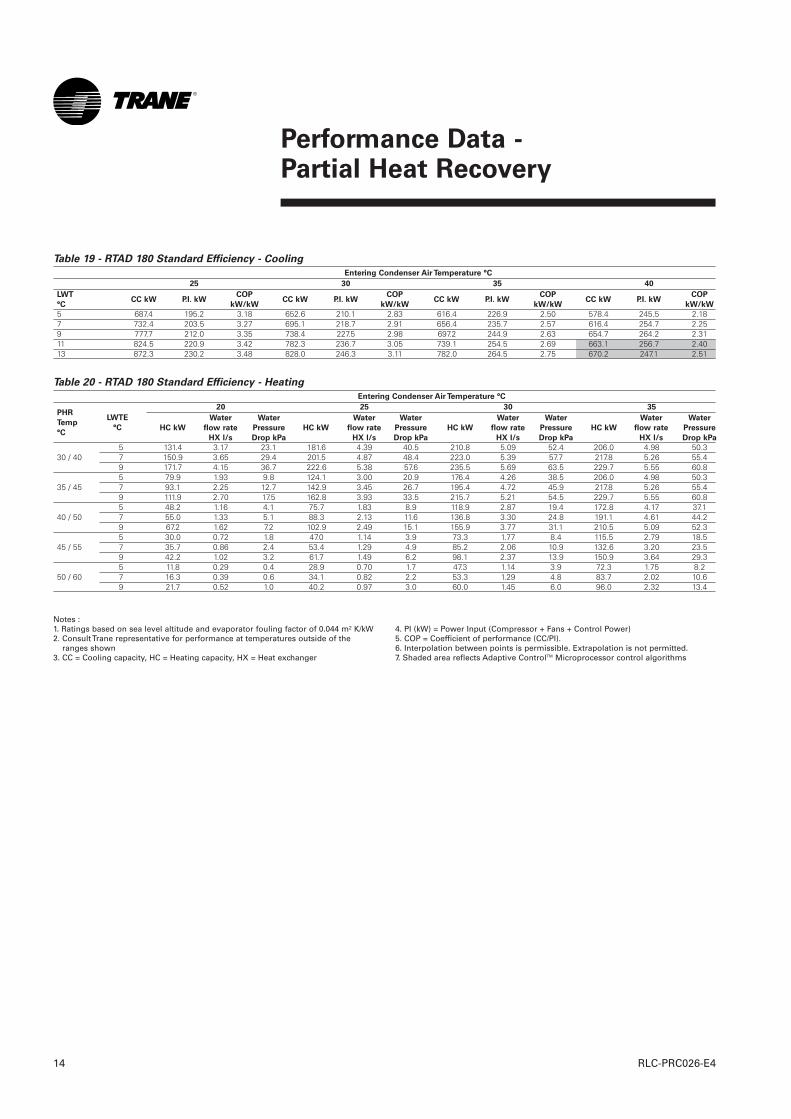
Table 19 - RTAD 180 Standard Efficiency - Cooling
Entering Condenser Air Temperature °C
25 30 35 40
5 687.4 195.2 3.18 652.6 210.1 2.83 616.4 226.9 2.50 578.4 245.5 2.187 732.4 203.5 3.27 695.1 218.7 2.91 656.4 235.7 2.57 616.4 254.7 2.259 777.7 212.0 3.35 738.4 227.5 2.98 697.2 244.9 2.63 654.7 264.2 2.3111 824.5 220.9 3.42 782.3 236.7 3.05 739.1 254.5 2.69 663.1 256.7 2.4013 872.3 230.2 3.48 828.0 246.3 3.11 782.0 264.5 2.75 670.2 247.1 2.51
Table 20 - RTAD 180 Standard Efficiency - Heating
Entering Condenser Air Temperature °C
20 25 30 35
5 131.4 3.17 23.1 181.6 4.39 40.5 210.8 5.09 52.4 206.0 4.98 50.330 / 40 7 150.9 3.65 29.4 201.5 4.87 48.4 223.0 5.39 57.7 217.8 5.26 55.4
9 171.7 4.15 36.7 222.6 5.38 57.6 235.5 5.69 63.5 229.7 5.55 60.85 79.9 1.93 9.8 124.1 3.00 20.9 176.4 4.26 38.5 206.0 4.98 50.3
35 / 45 7 93.1 2.25 12.7 142.9 3.45 26.7 195.4 4.72 45.9 217.8 5.26 55.49 111.9 2.70 17.5 162.8 3.93 33.5 215.7 5.21 54.5 229.7 5.55 60.85 48.2 1.16 4.1 75.7 1.83 8.9 118.9 2.87 19.4 172.8 4.17 37.1
40 / 50 7 55.0 1.33 5.1 88.3 2.13 11.6 136.8 3.30 24.8 191.1 4.61 44.29 67.2 1.62 7.2 102.9 2.49 15.1 155.9 3.77 31.1 210.5 5.09 52.35 30.0 0.72 1.8 47.0 1.14 3.9 73.3 1.77 8.4 115.5 2.79 18.5
45 / 55 7 35.7 0.86 2.4 53.4 1.29 4.9 85.2 2.06 10.9 132.6 3.20 23.59 42.2 1.02 3.2 61.7 1.49 6.2 98.1 2.37 13.9 150.9 3.64 29.35 11.8 0.29 0.4 28.9 0.70 1.7 47.3 1.14 3.9 72.3 1.75 8.2
50 / 60 7 16.3 0.39 0.6 34.1 0.82 2.2 53.3 1.29 4.8 83.7 2.02 10.69 21.7 0.52 1.0 40.2 0.97 3.0 60.0 1.45 6.0 96.0 2.32 13.4
LWT
°CCC kW P.I. kW
COP
kW/kWCC kW P.I. kW
COP
kW/kWCC kW P.I. kW
COP
kW/kWCC kW P.I. kW
COP
kW/kW
PHR
Temp
°C
LWTE
°C HC kW
Water
flow rate
HX l/s
Water
Pressure
Drop kPa
HC kW
Water
flow rate
HX l/s
Water
Pressure
Drop kPa
HC kW
Water
flow rate
HX l/s
Water
Pressure
Drop kPa
HC kW
Water
flow rate
HX l/s
Water
Pressure
Drop kPa
Notes :1. Ratings based on sea level altitude and evaporator fouling factor of 0.044 m² K/kW2. Consult Trane representative for performance at temperatures outside of the
ranges shown3. CC = Cooling capacity, HC = Heating capacity, HX = Heat exchanger
4. PI (kW) = Power Input (Compressor + Fans + Control Power)5. COP = Coefficient of performance (CC/PI).6. Interpolation between points is permissible. Extrapolation is not permitted.7. Shaded area reflects Adaptive ControlTM Microprocessor control algorithms
Performance Data - Partial Heat Recovery
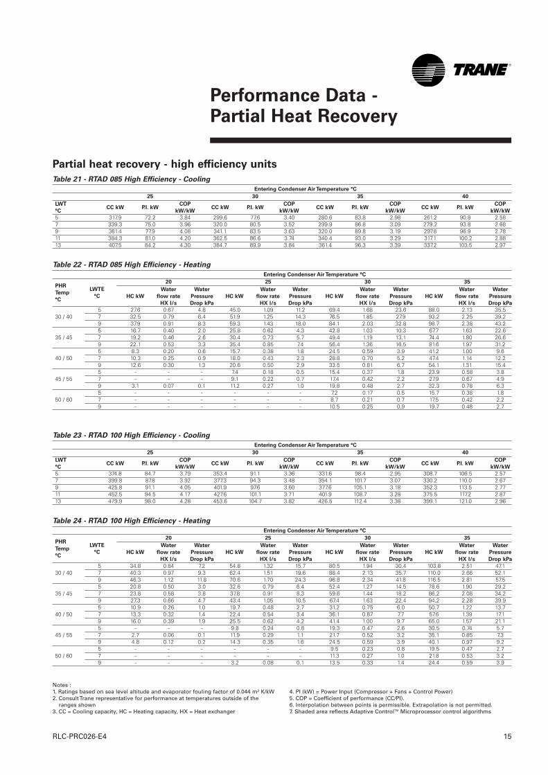
15RLC-PRC026-E4
Table 21 - RTAD 085 High Efficiency - Cooling
Entering Condenser Air Temperature °C
25 30 35 40
5 317.9 72.2 3.84 299.6 77.6 3.40 280.6 83.8 2.98 261.2 90.8 2.587 339.3 75.0 3.96 320.0 80.5 3.52 299.9 86.8 3.09 279.2 93.8 2.689 361.4 77.9 4.08 341.1 83.5 3.63 320.0 89.8 3.19 297.8 96.9 2.7811 384.3 81.0 4.20 362.5 86.6 3.74 340.4 93.0 3.29 317.1 100.2 2.8813 407.5 84.2 4.30 384.7 89.9 3.84 361.4 96.3 3.39 337.2 103.5 2.97
Table 22 - RTAD 085 High Efficiency - Heating
Entering Condenser Air Temperature °C
20 25 30 35
5 27.6 0.67 4.8 45.0 1.09 11.2 69.4 1.68 23.6 88.0 2.13 35.530 / 40 7 32.5 0.79 6.4 51.9 1.25 14.3 76.5 1.85 27.9 93.2 2.25 39.2
9 37.9 0.91 8.3 59.3 1.43 18.0 84.1 2.03 32.8 98.7 2.38 43.25 16.7 0.40 2.0 25.8 0.62 4.3 42.8 1.03 10.3 67.7 1.63 22.6
35 / 45 7 19.2 0.46 2.6 30.4 0.73 5.7 49.4 1.19 13.1 74.4 1.80 26.69 22.1 0.53 3.3 35.4 0.85 7.4 56.4 1.36 16.5 81.6 1.97 31.25 8.3 0.20 0.6 15.7 0.38 1.8 24.5 0.59 3.9 41.2 1.00 9.6
40 / 50 7 10.3 0.25 0.9 18.0 0.43 2.3 28.8 0.70 5.2 47.4 1.14 12.29 12.6 0.30 1.3 20.6 0.50 2.9 33.5 0.81 6.7 54.1 1.31 15.45 - - - 7.4 0.18 0.5 15.4 0.37 1.8 23.9 0.58 3.8
45 / 55 7 - - - 9.1 0.22 0.7 17.4 0.42 2.2 27.9 0.67 4.99 3.1 0.07 0.1 11.2 0.27 1.0 19.8 0.48 2.7 32.3 0.78 6.35 - - - - - - 7.2 0.17 0.5 15.7 0.38 1.8
50 / 60 7 - - - - - - 8.7 0.21 0.7 17.5 0.42 2.29 - - - - - - 10.5 0.25 0.9 19.7 0.48 2.7
LWT
°CCC kW P.I. kW
COP
kW/kWCC kW P.I. kW
COP
kW/kWCC kW P.I. kW
COP
kW/kWCC kW P.I. kW
COP
kW/kW
PHR
Temp
°C
LWTE
°C HC kW
Water
flow rate
HX l/s
Water
Pressure
Drop kPa
HC kW
Water
flow rate
HX l/s
Water
Pressure
Drop kPa
HC kW
Water
flow rate
HX l/s
Water
Pressure
Drop kPa
HC kW
Water
flow rate
HX l/s
Water
Pressure
Drop kPa
Table 23 - RTAD 100 High Efficiency - Cooling
Entering Condenser Air Temperature °C
25 30 35 40
5 374.8 84.7 3.79 353.4 91.1 3.36 331.6 98.4 2.95 308.7 106.5 2.577 399.8 87.8 3.92 377.3 94.3 3.48 354.1 101.7 3.07 330.2 110.0 2.679 425.8 91.1 4.05 401.9 97.6 3.60 377.6 105.1 3.18 352.3 113.5 2.7711 452.5 94.5 4.17 427.6 101.1 3.71 401.9 108.7 3.28 375.5 117.2 2.8713 479.9 98.0 4.28 453.6 104.7 3.82 426.5 112.4 3.38 399.1 121.0 2.96
Table 24 - RTAD 100 High Efficiency - Heating
Entering Condenser Air Temperature °C
20 25 30 35
5 34.8 0.84 7.2 54.8 1.32 15.7 80.5 1.94 30.4 103.8 2.51 47.130 / 40 7 40.3 0.97 9.3 62.4 1.51 19.6 88.4 2.13 35.7 110.0 2.66 52.1
9 46.3 1.12 11.8 70.6 1.70 24.3 96.8 2.34 41.8 116.5 2.81 57.55 20.8 0.50 3.0 32.6 0.79 6.4 52.4 1.27 14.5 78.6 1.90 29.2
35 / 45 7 23.8 0.58 3.8 37.8 0.91 8.3 59.6 1.44 18.2 86.2 2.08 34.29 27.3 0.66 4.7 43.4 1.05 10.5 67.4 1.63 22.4 94.2 2.28 39.95 10.9 0.26 1.0 19.7 0.48 2.7 31.2 0.75 6.0 50.7 1.22 13.7
40 / 50 7 13.3 0.32 1.4 22.4 0.54 3.4 36.1 0.87 7.7 57.6 1.39 17.19 16.0 0.39 1.9 25.5 0.62 4.2 41.4 1.00 9.7 65.0 1.57 21.15 - - - 9.8 0.24 0.8 19.3 0.47 2.6 30.5 0.74 5.7
45 / 55 7 2.7 0.06 0.1 11.9 0.29 1.1 21.7 0.52 3.2 35.1 0.85 7.39 4.8 0.12 0.2 14.3 0.35 1.6 24.5 0.59 3.9 40.1 0.97 9.25 - - - - - - 9.5 0.23 0.8 19.5 0.47 2.7
50 / 60 7 - - - - - - 11.3 0.27 1.0 21.8 0.53 3.29 - - - 3.2 0.08 0.1 13.5 0.33 1.4 24.4 0.59 3.9
LWT
°CCC kW P.I. kW
COP
kW/kWCC kW P.I. kW
COP
kW/kWCC kW P.I. kW
COP
kW/kWCC kW P.I. kW
COP
kW/kW
PHR
Temp
°C
LWTE
°C HC kW
Water
flow rate
HX l/s
Water
Pressure
Drop kPa
HC kW
Water
flow rate
HX l/s
Water
Pressure
Drop kPa
HC kW
Water
flow rate
HX l/s
Water
Pressure
Drop kPa
HC kW
Water
flow rate
HX l/s
Water
Pressure
Drop kPa
Notes :1. Ratings based on sea level altitude and evaporator fouling factor of 0.044 m² K/kW2. Consult Trane representative for performance at temperatures outside of the
ranges shown3. CC = Cooling capacity, HC = Heating capacity, HX = Heat exchanger
4. PI (kW) = Power Input (Compressor + Fans + Control Power)5. COP = Coefficient of performance (CC/PI).6. Interpolation between points is permissible. Extrapolation is not permitted.7. Shaded area reflects Adaptive ControlTM Microprocessor control algorithms
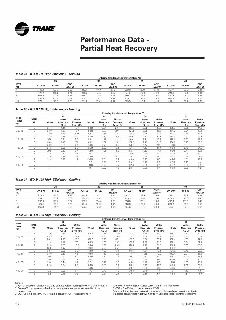
Partial heat recovery - high efficiency units
Performance Data - Partial Heat Recovery
RLC-PRC026-E416
Table 25 - RTAD 115 High Efficiency - Cooling
Entering Condenser Air Temperature °C
25 30 35 40
5 443.4 109.2 3.60 419.1 118.0 3.18 393.8 127.9 2.79 367.8 139.0 2.417 474.0 113.3 3.73 448.3 122.2 3.30 421.6 132.2 2.89 393.8 143.5 2.519 505.6 117.5 3.85 478.2 126.5 3.41 450.1 136.8 3.00 420.9 148.2 2.6111 538.3 121.9 3.97 509.5 131.1 3.52 479.2 141.5 3.09 448.6 153.1 2.7013 572.1 126.6 4.08 541.1 135.9 3.62 509.5 146.4 3.19 477.1 158.2 2.78
Table 26 - RTAD 115 High Efficiency - Heating
Entering Condenser Air Temperature °C
20 25 30 35
5 54.4 1.31 10.7 84.3 2.04 22.4 116.6 2.82 39.0 126.7 3.06 44.930 / 40 7 62.9 1.52 13.7 94.8 2.29 27.4 127.4 3.08 45.3 134.3 3.24 49.6
9 73.9 1.78 17.9 105.9 2.56 33.1 138.9 3.35 52.4 142.3 3.44 54.65 32.5 0.79 4.5 52.0 1.26 9.9 81.6 1.97 21.2 114.7 2.77 37.9
35 / 45 7 37.6 0.91 5.7 59.1 1.43 12.3 91.6 2.21 25.9 125.0 3.02 43.99 45.0 1.09 7.7 69.2 1.67 16.1 102.3 2.47 31.2 136.0 3.29 50.65 20.9 0.51 2.1 31.6 0.76 4.2 50.7 1.22 9.5 79.8 1.93 20.5
40 / 50 7 24.2 0.58 2.7 35.3 0.85 5.1 57.4 1.39 11.7 89.4 2.16 24.89 27.9 0.67 3.4 42.0 1.01 6.9 65.7 1.59 14.7 99.6 2.41 29.85 9.3 0.22 0.5 20.1 0.49 2.0 31.6 0.76 4.2 50.3 1.21 9.3
45 / 55 7 11.8 0.28 0.8 23.0 0.56 2.5 35.1 0.85 5.1 56.7 1.37 11.49 14.8 0.36 1.2 26.5 0.64 3.1 40.0 0.97 6.3 63.6 1.54 13.95 - - - 8.5 0.21 0.5 20.2 0.49 2.0 32.5 0.79 4.4
50 / 60 7 - - - 10.8 0.26 0.7 22.9 0.55 2.5 35.7 0.86 5.29 - - - 13.4 0.32 1.0 26.1 0.63 3.1 39.4 0.95 6.2
LWT
°CCC kW P.I. kW
COP
kW/kWCC kW P.I. kW
COP
kW/kWCC kW P.I. kW
COP
kW/kWCC kW P.I. kW
COP
kW/kW
PHR
Temp
°C
LWTE
°C HC kW
Water
flow rate
HX l/s
Water
Pressure
Drop kPa
HC kW
Water
flow rate
HX l/s
Water
Pressure
Drop kPa
HC kW
Water
flow rate
HX l/s
Water
Pressure
Drop kPa
HC kW
Water
flow rate
HX l/s
Water
Pressure
Drop kPa
Table 27 - RTAD 125 High Efficiency - Cooling
Entering Condenser Air Temperature °C
25 30 35 40
5 519.3 133.2 3.45 490.8 144.1 3.04 461.7 156.3 2.66 431.4 169.8 2.317 554.1 138.2 3.56 524.2 149.2 3.15 493.3 161.6 2.76 461.3 175.3 2.409 590.3 143.4 3.67 558.7 154.6 3.25 526.0 167.1 2.86 492.6 181.0 2.4911 627.6 148.8 3.78 594.2 160.2 3.35 559.8 172.9 2.95 524.2 186.8 2.5813 666.3 154.5 3.88 630.8 166.0 3.45 594.6 178.8 3.04 557.3 192.9 2.66
Table 28 - RTAD 125 High Efficiency - Heating
Entering Condenser Air Temperature °C
20 25 30 35
5 71.9 1.74 17.1 105.5 2.55 32.9 140.0 3.38 53.2 150.3 3.63 60.030 / 40 7 83.5 2.02 22.1 117.5 2.84 39.5 152.4 3.68 61.4 159.2 3.84 66.1
9 96.1 2.32 28.0 130.3 3.15 47.1 165.5 4.00 70.7 168.4 4.07 72.85 44.4 1.07 7.6 68.3 1.65 15.7 102.9 2.49 31.5 138.4 3.34 52.1
35 / 45 7 52.3 1.26 10.0 79.4 1.92 20.3 114.4 2.76 37.7 150.2 3.63 59.99 61.0 1.47 13.0 91.3 2.20 25.7 126.6 3.06 44.8 162.8 3.93 68.75 28.7 0.69 3.6 42.3 1.02 7.0 66.7 1.61 15.1 101.5 2.45 30.8
40 / 50 7 33.0 0.80 4.6 49.8 1.20 9.2 76.4 1.85 19.0 112.4 2.71 36.69 37.8 0.91 5.7 58.0 1.40 11.9 87.7 2.12 24.0 124.1 3.00 43.35 15.0 0.36 1.2 28.2 0.68 3.5 42.2 1.02 6.9 66.6 1.61 15.0
45 / 55 7 18.4 0.44 1.7 32.1 0.77 4.3 48.4 1.17 8.7 74.6 1.80 18.29 22.3 0.54 2.3 36.5 0.88 5.4 56.1 1.36 11.2 85.4 2.06 22.95 - - - 14.6 0.35 1.1 28.7 0.69 3.6 43.5 1.05 7.3
50 / 60 7 3.8 0.09 0.1 17.6 0.42 1.6 32.2 0.78 4.4 48.1 1.16 8.69 6.8 0.16 0.3 21.1 0.51 2.1 36.3 0.88 5.4 55.4 1.34 11.0
LWT
°CCC kW P.I. kW
COP
kW/kWCC kW P.I. kW
COP
kW/kWCC kW P.I. kW
COP
kW/kWCC kW P.I. kW
COP
kW/kW
PHR
Temp
°C
LWTE
°C HC kW
Water
flow rate
HX l/s
Water
Pressure
Drop kPa
HC kW
Water
flow rate
HX l/s
Water
Pressure
Drop kPa
HC kW
Water
flow rate
HX l/s
Water
Pressure
Drop kPa
HC kW
Water
flow rate
HX l/s
Water
Pressure
Drop kPa
Notes :1. Ratings based on sea level altitude and evaporator fouling factor of 0.044 m² K/kW2. Consult Trane representative for performance at temperatures outside of the
ranges shown3. CC = Cooling capacity, HC = Heating capacity, HX = Heat exchanger
4. PI (kW) = Power Input (Compressor + Fans + Control Power)5. COP = Coefficient of performance (CC/PI).6. Interpolation between points is permissible. Extrapolation is not permitted.7. Shaded area reflects Adaptive ControlTM Microprocessor control algorithms
Performance Data - Partial Heat Recovery
17RLC-PRC026-E4
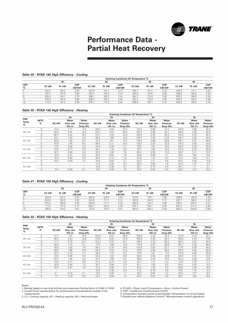
Table 29 - RTAD 145 High Efficiency - Cooling
Entering Condenser Air Temperature °C
25 30 35 40
5 553.4 138.2 3.52 524.9 149.1 3.13 495.1 161.4 2.75 464.5 175.1 2.407 591.4 143.6 3.64 561.2 154.6 3.24 529.5 167.0 2.85 496.8 180.8 2.509 630.4 149.1 3.75 598.1 160.3 3.34 564.7 172.8 2.95 530.2 186.8 2.5911 670.5 154.9 3.86 636.4 166.2 3.44 601.2 178.9 3.05 565.0 193.0 2.6813 712.0 161.0 3.96 676.1 172.3 3.54 638.9 185.1 3.14 600.5 199.3 2.76
Table 30 - RTAD 145 High Efficiency - Heating
Entering Condenser Air Temperature °C
20 25 30 35
5 73.4 1.77 11.5 109.4 2.64 23.3 151.4 3.66 41.2 159.9 3.86 45.430 / 40 7 83.3 2.01 14.4 123.1 2.97 28.6 165.3 3.99 48.1 169.4 4.09 50.2
9 96.7 2.34 18.7 137.7 3.33 34.9 180.2 4.35 56.0 179.3 4.33 55.55 43.1 1.04 4.5 69.9 1.69 10.6 105.5 2.55 21.8 148.7 3.59 40.0
35 / 45 7 52.0 1.26 6.3 79.3 1.91 13.2 118.5 2.86 26.8 162.1 3.91 46.59 61.8 1.49 8.5 89.9 2.17 16.5 132.5 3.20 32.6 176.3 4.26 53.95 27.5 0.66 2.0 40.9 0.99 4.1 67.8 1.64 10.0 103.0 2.49 20.9
40 / 50 7 31.8 0.77 2.6 48.1 1.16 5.5 76.7 1.85 12.5 115.4 2.79 25.69 36.7 0.89 3.4 57.3 1.38 7.5 86.2 2.08 15.3 128.7 3.11 31.05 12.9 0.31 0.5 26.4 0.64 1.9 40.9 0.99 4.1 67.0 1.62 9.8
45 / 55 7 16.3 0.39 0.8 30.3 0.73 2.4 45.6 1.10 5.0 75.3 1.82 12.19 20.3 0.49 1.2 34.8 0.84 3.1 54.2 1.31 6.8 84.4 2.04 14.85 - - - 11.9 0.29 0.5 26.5 0.64 1.9 42.0 1.01 4.3
50 / 60 7 - - - 14.9 0.36 0.7 30.1 0.73 2.4 46.1 1.11 5.19 3.9 0.09 0.1 18.5 0.45 1.0 34.2 0.83 3.0 52.5 1.27 6.4
LWT
°CCC kW P.I. kW
COP
kW/kWCC kW P.I. kW
COP
kW/kWCC kW P.I. kW
COP
kW/kWCC kW P.I. kW
COP
kW/kW
PHR
Temp
°C
LWTE
°C HC kW
Water
flow rate
HX l/s
Water
Pressure
Drop kPa
HC kW
Water
flow rate
HX l/s
Water
Pressure
Drop kPa
HC kW
Water
flow rate
HX l/s
Water
Pressure
Drop kPa
HC kW
Water
flow rate
HX l/s
Water
Pressure
Drop kPa
Table 31 - RTAD 150 High Efficiency - Cooling
Entering Condenser Air Temperature °C
25 30 35 40
5 594.6 153.2 3.42 563.6 164.9 3.04 531.6 178.1 2.68 498.6 192.9 2.347 634.6 159.3 3.52 601.6 171.1 3.14 567.8 184.6 2.77 532.7 199.5 2.439 675.4 165.6 3.62 640.6 177.7 3.23 604.8 191.2 2.86 567.5 206.3 2.5111 717.3 172.3 3.72 680.7 184.4 3.32 642.7 198.1 2.94 603.4 213.3 2.5913 760.5 179.2 3.81 721.8 191.5 3.41 681.8 205.2 3.03 640.3 220.6 2.66
Table 32 - RTAD 150 High Efficiency - Heating
Entering Condenser Air Temperature °C
20 25 30 35
5 81.7 1.97 13.9 122.9 2.97 28.6 165.6 4.00 48.3 172.9 4.18 52.130 / 40 7 96.2 2.32 18.6 137.6 3.32 34.9 180.6 4.36 56.2 183.0 4.42 57.6
9 111.7 2.70 24.1 153.3 3.70 42.1 196.5 4.75 65.2 193.4 4.67 63.55 49.2 1.19 5.7 77.0 1.86 12.5 118.6 2.87 26.8 162.7 3.93 46.8
35 / 45 7 58.9 1.42 7.8 89.5 2.16 16.4 132.6 3.20 32.7 177.0 4.28 54.39 69.5 1.68 10.5 104.2 2.52 21.4 147.5 3.56 39.4 192.3 4.64 62.85 32.4 0.78 2.7 46.8 1.13 5.2 74.8 1.81 11.9 115.9 2.80 25.8
40 / 50 7 37.4 0.90 3.5 54.8 1.32 6.9 84.6 2.04 14.8 129.2 3.12 31.29 43.1 1.04 4.5 64.7 1.56 9.2 98.6 2.38 19.4 143.4 3.46 37.55 16.8 0.41 0.9 31.2 0.75 2.6 46.7 1.13 5.2 73.9 1.79 11.7
45 / 55 7 20.8 0.50 1.3 35.7 0.86 3.3 52.1 1.26 6.3 83.0 2.00 14.39 25.4 0.61 1.8 41.0 0.99 4.1 61.5 1.49 8.4 94.6 2.28 18.05 - - - 15.6 0.38 0.8 31.2 0.75 2.6 47.8 1.15 5.4
50 / 60 7 4.1 0.10 0.1 19.2 0.46 1.1 35.3 0.85 3.2 52.6 1.27 6.49 7.7 0.19 0.2 23.4 0.56 1.5 40.2 0.97 4.0 59.7 1.44 8.0
LWT
°CCC kW P.I. kW
COP
kW/kWCC kW P.I. kW
COP
kW/kWCC kW P.I. kW
COP
kW/kWCC kW P.I. kW
COP
kW/kW
PHR
Temp
°C
LWTE
°C HC kW
Water
flow rate
HX l/s
Water
Pressure
Drop kPa
HC kW
Water
flow rate
HX l/s
Water
Pressure
Drop kPa
HC kW
Water
flow rate
HX l/s
Water
Pressure
Drop kPa
HC kW
Water
flow rate
HX l/s
Water
Pressure
Drop kPa
Notes :1. Ratings based on sea level altitude and evaporator fouling factor of 0.044 m² K/kW2. Consult Trane representative for performance at temperatures outside of the
ranges shown3. CC = Cooling capacity, HC = Heating capacity, HX = Heat exchanger
4. PI (kW) = Power Input (Compressor + Fans + Control Power)5. COP = Coefficient of performance (CC/PI).6. Interpolation between points is permissible. Extrapolation is not permitted.7. Shaded area reflects Adaptive ControlTM Microprocessor control algorithms
Performance Data - Partial Heat Recovery
RLC-PRC026-E418
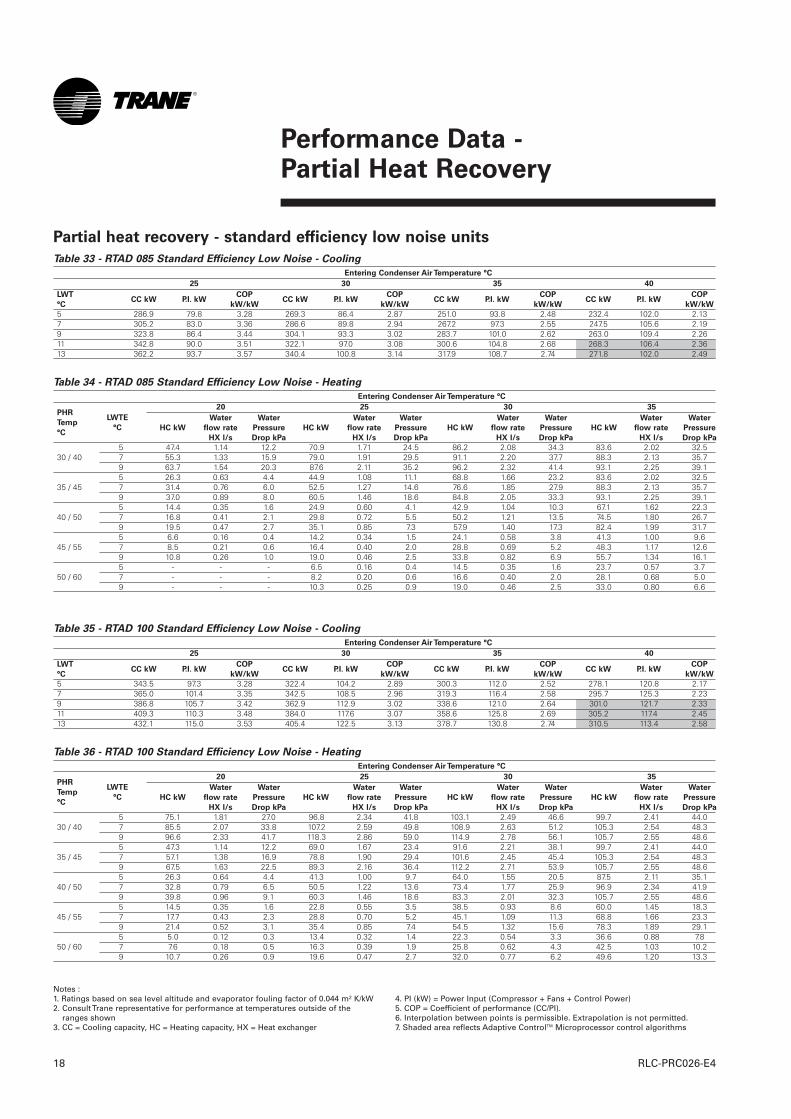
Table 33 - RTAD 085 Standard Efficiency Low Noise - Cooling
Entering Condenser Air Temperature °C
25 30 35 40
5 286.9 79.8 3.28 269.3 86.4 2.87 251.0 93.8 2.48 232.4 102.0 2.137 305.2 83.0 3.36 286.6 89.8 2.94 267.2 97.3 2.55 247.5 105.6 2.199 323.8 86.4 3.44 304.1 93.3 3.02 283.7 101.0 2.62 263.0 109.4 2.2611 342.8 90.0 3.51 322.1 97.0 3.08 300.6 104.8 2.68 268.3 106.4 2.3613 362.2 93.7 3.57 340.4 100.8 3.14 317.9 108.7 2.74 271.8 102.0 2.49
Table 34 - RTAD 085 Standard Efficiency Low Noise - Heating
Entering Condenser Air Temperature °C
20 25 30 35
5 47.4 1.14 12.2 70.9 1.71 24.5 86.2 2.08 34.3 83.6 2.02 32.530 / 40 7 55.3 1.33 15.9 79.0 1.91 29.5 91.1 2.20 37.7 88.3 2.13 35.7
9 63.7 1.54 20.3 87.6 2.11 35.2 96.2 2.32 41.4 93.1 2.25 39.15 26.3 0.63 4.4 44.9 1.08 11.1 68.8 1.66 23.2 83.6 2.02 32.5
35 / 45 7 31.4 0.76 6.0 52.5 1.27 14.6 76.6 1.85 27.9 88.3 2.13 35.79 37.0 0.89 8.0 60.5 1.46 18.6 84.8 2.05 33.3 93.1 2.25 39.15 14.4 0.35 1.6 24.9 0.60 4.1 42.9 1.04 10.3 67.1 1.62 22.3
40 / 50 7 16.8 0.41 2.1 29.8 0.72 5.5 50.2 1.21 13.5 74.5 1.80 26.79 19.5 0.47 2.7 35.1 0.85 7.3 57.9 1.40 17.3 82.4 1.99 31.75 6.6 0.16 0.4 14.2 0.34 1.5 24.1 0.58 3.8 41.3 1.00 9.6
45 / 55 7 8.5 0.21 0.6 16.4 0.40 2.0 28.8 0.69 5.2 48.3 1.17 12.69 10.8 0.26 1.0 19.0 0.46 2.5 33.8 0.82 6.9 55.7 1.34 16.15 - - - 6.5 0.16 0.4 14.5 0.35 1.6 23.7 0.57 3.7
50 / 60 7 - - - 8.2 0.20 0.6 16.6 0.40 2.0 28.1 0.68 5.09 - - - 10.3 0.25 0.9 19.0 0.46 2.5 33.0 0.80 6.6
LWT
°CCC kW P.I. kW
COP
kW/kWCC kW P.I. kW
COP
kW/kWCC kW P.I. kW
COP
kW/kWCC kW P.I. kW
COP
kW/kW
PHR
Temp
°C
LWTE
°C HC kW
Water
flow rate
HX l/s
Water
Pressure
Drop kPa
HC kW
Water
flow rate
HX l/s
Water
Pressure
Drop kPa
HC kW
Water
flow rate
HX l/s
Water
Pressure
Drop kPa
HC kW
Water
flow rate
HX l/s
Water
Pressure
Drop kPa
Table 35 - RTAD 100 Standard Efficiency Low Noise - Cooling
Entering Condenser Air Temperature °C
25 30 35 40
5 343.5 97.3 3.28 322.4 104.2 2.89 300.3 112.0 2.52 278.1 120.8 2.177 365.0 101.4 3.35 342.5 108.5 2.96 319.3 116.4 2.58 295.7 125.3 2.239 386.8 105.7 3.42 362.9 112.9 3.02 338.6 121.0 2.64 301.0 121.7 2.3311 409.3 110.3 3.48 384.0 117.6 3.07 358.6 125.8 2.69 305.2 117.4 2.4513 432.1 115.0 3.53 405.4 122.5 3.13 378.7 130.8 2.74 310.5 113.4 2.58
Table 36 - RTAD 100 Standard Efficiency Low Noise - Heating
Entering Condenser Air Temperature °C
20 25 30 35
5 75.1 1.81 27.0 96.8 2.34 41.8 103.1 2.49 46.6 99.7 2.41 44.030 / 40 7 85.5 2.07 33.8 107.2 2.59 49.8 108.9 2.63 51.2 105.3 2.54 48.3
9 96.6 2.33 41.7 118.3 2.86 59.0 114.9 2.78 56.1 105.7 2.55 48.65 47.3 1.14 12.2 69.0 1.67 23.4 91.6 2.21 38.1 99.7 2.41 44.0
35 / 45 7 57.1 1.38 16.9 78.8 1.90 29.4 101.6 2.45 45.4 105.3 2.54 48.39 67.5 1.63 22.5 89.3 2.16 36.4 112.2 2.71 53.9 105.7 2.55 48.65 26.3 0.64 4.4 41.3 1.00 9.7 64.0 1.55 20.5 87.5 2.11 35.1
40 / 50 7 32.8 0.79 6.5 50.5 1.22 13.6 73.4 1.77 25.9 96.9 2.34 41.99 39.8 0.96 9.1 60.3 1.46 18.6 83.3 2.01 32.3 105.7 2.55 48.65 14.5 0.35 1.6 22.8 0.55 3.5 38.5 0.93 8.6 60.0 1.45 18.3
45 / 55 7 17.7 0.43 2.3 28.8 0.70 5.2 45.1 1.09 11.3 68.8 1.66 23.39 21.4 0.52 3.1 35.4 0.85 7.4 54.5 1.32 15.6 78.3 1.89 29.15 5.0 0.12 0.3 13.4 0.32 1.4 22.3 0.54 3.3 36.6 0.88 7.8
50 / 60 7 7.6 0.18 0.5 16.3 0.39 1.9 25.8 0.62 4.3 42.5 1.03 10.29 10.7 0.26 0.9 19.6 0.47 2.7 32.0 0.77 6.2 49.6 1.20 13.3
LWT
°CCC kW P.I. kW
COP
kW/kWCC kW P.I. kW
COP
kW/kWCC kW P.I. kW
COP
kW/kWCC kW P.I. kW
COP
kW/kW
PHR
Temp
°C
LWTE
°C HC kW
Water
flow rate
HX l/s
Water
Pressure
Drop kPa
HC kW
Water
flow rate
HX l/s
Water
Pressure
Drop kPa
HC kW
Water
flow rate
HX l/s
Water
Pressure
Drop kPa
HC kW
Water
flow rate
HX l/s
Water
Pressure
Drop kPa
Notes :1. Ratings based on sea level altitude and evaporator fouling factor of 0.044 m² K/kW2. Consult Trane representative for performance at temperatures outside of the
ranges shown3. CC = Cooling capacity, HC = Heating capacity, HX = Heat exchanger
4. PI (kW) = Power Input (Compressor + Fans + Control Power)5. COP = Coefficient of performance (CC/PI).6. Interpolation between points is permissible. Extrapolation is not permitted.7. Shaded area reflects Adaptive ControlTM Microprocessor control algorithms
Partial heat recovery - standard efficiency low noise units

Performance Data - Partial Heat Recovery
19RLC-PRC026-E4
Table 37- RTAD 115 Standard Efficiency Low Noise - Cooling
Entering Condenser Air Temperature °C
25 30 35 40
5 405.0 124.0 3.08 379.4 134.5 2.68 353.4 146.3 2.30 318.9 154.0 1.987 429.3 129.2 3.14 402.2 140.0 2.73 374.5 152.0 2.35 323.1 149.3 2.079 453.9 134.7 3.19 425.1 145.7 2.78 395.6 158.0 2.40 328.4 144.8 2.1611 478.5 140.4 3.24 448.3 151.7 2.82 414.5 162.1 2.45 331.9 140.6 2.2413 503.5 146.4 3.28 471.5 157.9 2.86 420.2 156.5 2.57 336.1 136.4 2.34
Table 38- RTAD 115 Standard Efficiency Low Noise - Heating
Entering Condenser Air Temperature °C
20 25 30 35
5 92.7 2.24 26.4 124.7 3.01 43.7 124.9 3.02 43.8 118.2 2.86 39.930 / 40 7 105.4 2.55 32.8 135.6 3.27 50.3 131.6 3.18 47.9 118.1 2.85 39.8
9 119.0 2.88 40.4 142.7 3.45 54.9 138.4 3.34 52.1 118.3 2.86 39.95 57.7 1.39 11.8 89.8 2.17 25.0 122.4 2.96 42.3 118.2 2.86 39.9
35 / 45 7 69.6 1.68 16.2 102.1 2.47 31.1 131.6 3.18 47.9 118.1 2.85 39.89 82.5 1.99 21.6 115.2 2.78 38.2 138.4 3.34 52.1 118.3 2.86 39.95 33.4 0.81 4.7 55.2 1.33 10.9 87.6 2.12 24.0 118.2 2.86 39.9
40 / 50 7 41.3 1.00 6.7 66.4 1.60 15.0 99.5 2.40 29.7 118.1 2.85 39.89 49.9 1.20 9.2 78.8 1.90 20.0 112.1 2.71 36.5 118.3 2.86 39.95 21.0 0.51 2.1 32.5 0.78 4.4 54.5 1.32 10.7 86.0 2.08 23.2
45 / 55 7 24.7 0.60 2.8 39.7 0.96 6.2 64.0 1.54 14.0 97.5 2.36 28.89 29.1 0.70 3.7 47.9 1.16 8.6 75.9 1.83 18.8 109.7 2.65 35.15 9.6 0.23 0.6 21.2 0.51 2.1 33.3 0.80 4.6 54.5 1.32 10.7
50 / 60 7 12.6 0.30 0.9 24.7 0.60 2.8 38.8 0.94 6.0 62.2 1.50 13.49 16.2 0.39 1.4 28.9 0.70 3.6 46.8 1.13 8.2 73.6 1.78 17.8
LWT
°CCC kW P.I. kW
COP
kW/kWCC kW P.I. kW
COP
kW/kWCC kW P.I. kW
COP
kW/kWCC kW P.I. kW
COP
kW/kW
PHR
Temp
°C
LWTE
°C HC kW
Water
flow rate
HX l/s
Water
Pressure
Drop kPa
HC kW
Water
flow rate
HX l/s
Water
Pressure
Drop kPa
HC kW
Water
flow rate
HX l/s
Water
Pressure
Drop kPa
HC kW
Water
flow rate
HX l/s
Water
Pressure
Drop kPa
Table 39 - RTAD 125 Standard Efficiency Low Noise - Cooling
Entering Condenser Air Temperature °C
25 30 35 40
5 459.2 160.0 2.74 429.0 173.6 2.37 391.0 183.1 2.06 311.2 160.8 1.857 484.5 167.0 2.78 452.5 180.9 2.41 397.0 177.5 2.15 315.4 155.9 1.939 510.5 174.3 2.81 476.8 188.5 2.44 404.0 172.1 2.25 320.3 152.3 2.0111 536.2 182.0 2.83 491.5 188.7 2.51 408.9 166.2 2.36 323.1 147.9 2.0813 562.2 189.9 2.85 497.9 181.8 2.63 415.2 161.8 2.46 327.3 143.9 2.17
Table 40 - RTAD 125 Standard Efficiency Low Noise - heating
Entering Condenser Air Temperature °C
20 25 30 35
5 134.6 3.25 49.7 150.6 3.64 60.2 143.5 3.47 55.5 118.0 2.85 39.830 / 40 7 150.4 3.63 60.1 158.4 3.82 65.5 143.6 3.47 55.5 117.8 2.85 39.7
9 167.4 4.04 72.0 166.3 4.02 71.2 144.0 3.48 55.8 118.2 2.85 39.95 97.5 2.36 28.8 132.0 3.19 48.1 143.5 3.47 55.5 118.0 2.85 39.8
35 / 45 7 112.4 2.72 36.6 147.4 3.56 58.0 143.6 3.47 55.5 117.8 2.85 39.79 128.5 3.10 46.0 163.7 3.95 69.3 144.0 3.48 55.8 118.2 2.85 39.95 61.3 1.48 13.1 95.1 2.30 27.5 130.1 3.14 46.9 118.0 2.85 39.8
40 / 50 7 74.4 1.80 18.2 109.5 2.65 35.0 143.6 3.47 55.5 117.8 2.85 39.79 89.7 2.17 24.9 125.0 3.02 43.8 144.0 3.48 55.8 118.2 2.85 39.95 36.9 0.89 5.5 60.5 1.46 12.8 93.3 2.25 26.7 118.0 2.85 39.8
45 / 55 7 45.4 1.10 7.9 71.7 1.73 17.1 107.3 2.59 33.8 117.8 2.85 39.79 55.9 1.35 11.2 86.3 2.08 23.3 122.1 2.95 42.1 118.2 2.85 39.95 23.4 0.57 2.6 37.8 0.91 5.7 60.4 1.46 12.8 92.3 2.23 26.2
50 / 60 7 28.2 0.68 3.5 44.5 1.07 7.6 70.0 1.69 16.4 105.7 2.55 33.09 33.9 0.82 4.8 54.4 1.31 10.7 83.6 2.02 22.1 118.2 2.85 39.9
LWT
°CCC kW P.I. kW
COP
kW/kWCC kW P.I. kW
COP
kW/kWCC kW P.I. kW
COP
kW/kWCC kW P.I. kW
COP
kW/kW
PHR
Temp
°C
LWTE
°C HC kW
Water
flow rate
HX l/s
Water
Pressure
Drop kPa
HC kW
Water
flow rate
HX l/s
Water
Pressure
Drop kPa
HC kW
Water
flow rate
HX l/s
Water
Pressure
Drop kPa
HC kW
Water
flow rate
HX l/s
Water
Pressure
Drop kPa
Notes :1. Ratings based on sea level altitude and evaporator fouling factor of 0.044 m² K/kW2. Consult Trane representative for performance at temperatures outside of the
ranges shown3. CC = Cooling capacity, HC = Heating capacity, HX = Heat exchanger
4. PI (kW) = Power Input (Compressor + Fans + Control Power)5. COP = Coefficient of performance (CC/PI).6. Interpolation between points is permissible. Extrapolation is not permitted.7. Shaded area reflects Adaptive ControlTM Microprocessor control algorithms
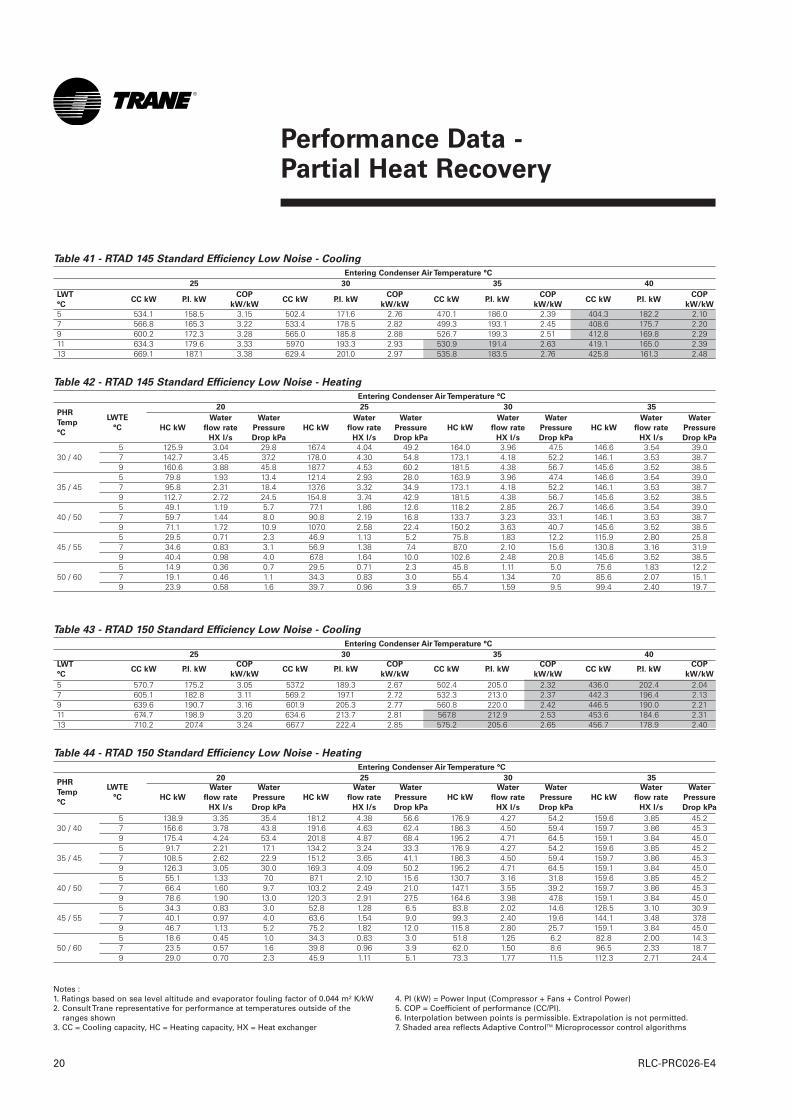
Table 41 - RTAD 145 Standard Efficiency Low Noise - Cooling
Entering Condenser Air Temperature °C
25 30 35 40
5 534.1 158.5 3.15 502.4 171.6 2.76 470.1 186.0 2.39 404.3 182.2 2.107 566.8 165.3 3.22 533.4 178.5 2.82 499.3 193.1 2.45 408.6 175.7 2.209 600.2 172.3 3.28 565.0 185.8 2.88 526.7 199.3 2.51 412.8 169.8 2.2911 634.3 179.6 3.33 597.0 193.3 2.93 530.9 191.4 2.63 419.1 165.0 2.3913 669.1 187.1 3.38 629.4 201.0 2.97 535.8 183.5 2.76 425.8 161.3 2.48
Table 42 - RTAD 145 Standard Efficiency Low Noise - Heating
Entering Condenser Air Temperature °C
20 25 30 35
5 125.9 3.04 29.8 167.4 4.04 49.2 164.0 3.96 47.5 146.6 3.54 39.030 / 40 7 142.7 3.45 37.2 178.0 4.30 54.8 173.1 4.18 52.2 146.1 3.53 38.7
9 160.6 3.88 45.8 187.7 4.53 60.2 181.5 4.38 56.7 145.6 3.52 38.55 79.8 1.93 13.4 121.4 2.93 28.0 163.9 3.96 47.4 146.6 3.54 39.0
35 / 45 7 95.8 2.31 18.4 137.6 3.32 34.9 173.1 4.18 52.2 146.1 3.53 38.79 112.7 2.72 24.5 154.8 3.74 42.9 181.5 4.38 56.7 145.6 3.52 38.55 49.1 1.19 5.7 77.1 1.86 12.6 118.2 2.85 26.7 146.6 3.54 39.0
40 / 50 7 59.7 1.44 8.0 90.8 2.19 16.8 133.7 3.23 33.1 146.1 3.53 38.79 71.1 1.72 10.9 107.0 2.58 22.4 150.2 3.63 40.7 145.6 3.52 38.55 29.5 0.71 2.3 46.9 1.13 5.2 75.8 1.83 12.2 115.9 2.80 25.8
45 / 55 7 34.6 0.83 3.1 56.9 1.38 7.4 87.0 2.10 15.6 130.8 3.16 31.99 40.4 0.98 4.0 67.8 1.64 10.0 102.6 2.48 20.8 145.6 3.52 38.55 14.9 0.36 0.7 29.5 0.71 2.3 45.8 1.11 5.0 75.6 1.83 12.2
50 / 60 7 19.1 0.46 1.1 34.3 0.83 3.0 55.4 1.34 7.0 85.6 2.07 15.19 23.9 0.58 1.6 39.7 0.96 3.9 65.7 1.59 9.5 99.4 2.40 19.7
LWT
°CCC kW P.I. kW
COP
kW/kWCC kW P.I. kW
COP
kW/kWCC kW P.I. kW
COP
kW/kWCC kW P.I. kW
COP
kW/kW
PHR
Temp
°C
LWTE
°C HC kW
Water
flow rate
HX l/s
Water
Pressure
Drop kPa
HC kW
Water
flow rate
HX l/s
Water
Pressure
Drop kPa
HC kW
Water
flow rate
HX l/s
Water
Pressure
Drop kPa
HC kW
Water
flow rate
HX l/s
Water
Pressure
Drop kPa
Notes :1. Ratings based on sea level altitude and evaporator fouling factor of 0.044 m² K/kW2. Consult Trane representative for performance at temperatures outside of the
ranges shown3. CC = Cooling capacity, HC = Heating capacity, HX = Heat exchanger
4. PI (kW) = Power Input (Compressor + Fans + Control Power)5. COP = Coefficient of performance (CC/PI).6. Interpolation between points is permissible. Extrapolation is not permitted.7. Shaded area reflects Adaptive ControlTM Microprocessor control algorithms
Performance Data - Partial Heat Recovery
RLC-PRC026-E420
Table 43 - RTAD 150 Standard Efficiency Low Noise - Cooling
Entering Condenser Air Temperature °C
25 30 35 40
5 570.7 175.2 3.05 537.2 189.3 2.67 502.4 205.0 2.32 436.0 202.4 2.047 605.1 182.8 3.11 569.2 197.1 2.72 532.3 213.0 2.37 442.3 196.4 2.139 639.6 190.7 3.16 601.9 205.3 2.77 560.8 220.0 2.42 446.5 190.0 2.2111 674.7 198.9 3.20 634.6 213.7 2.81 567.8 212.9 2.53 453.6 184.6 2.3113 710.2 207.4 3.24 667.7 222.4 2.85 575.2 205.6 2.65 456.7 178.9 2.40
Table 44 - RTAD 150 Standard Efficiency Low Noise - Heating
Entering Condenser Air Temperature °C
20 25 30 35
5 138.9 3.35 35.4 181.2 4.38 56.6 176.9 4.27 54.2 159.6 3.85 45.230 / 40 7 156.6 3.78 43.8 191.6 4.63 62.4 186.3 4.50 59.4 159.7 3.86 45.3
9 175.4 4.24 53.4 201.8 4.87 68.4 195.2 4.71 64.5 159.1 3.84 45.05 91.7 2.21 17.1 134.2 3.24 33.3 176.9 4.27 54.2 159.6 3.85 45.2
35 / 45 7 108.5 2.62 22.9 151.2 3.65 41.1 186.3 4.50 59.4 159.7 3.86 45.39 126.3 3.05 30.0 169.3 4.09 50.2 195.2 4.71 64.5 159.1 3.84 45.05 55.1 1.33 7.0 87.1 2.10 15.6 130.7 3.16 31.8 159.6 3.85 45.2
40 / 50 7 66.4 1.60 9.7 103.2 2.49 21.0 147.1 3.55 39.2 159.7 3.86 45.39 78.6 1.90 13.0 120.3 2.91 27.5 164.6 3.98 47.8 159.1 3.84 45.05 34.3 0.83 3.0 52.8 1.28 6.5 83.8 2.02 14.6 128.5 3.10 30.9
45 / 55 7 40.1 0.97 4.0 63.6 1.54 9.0 99.3 2.40 19.6 144.1 3.48 37.89 46.7 1.13 5.2 75.2 1.82 12.0 115.8 2.80 25.7 159.1 3.84 45.05 18.6 0.45 1.0 34.3 0.83 3.0 51.8 1.25 6.2 82.8 2.00 14.3
50 / 60 7 23.5 0.57 1.6 39.8 0.96 3.9 62.0 1.50 8.6 96.5 2.33 18.79 29.0 0.70 2.3 45.9 1.11 5.1 73.3 1.77 11.5 112.3 2.71 24.4
Performance Data - Partial Heat Recovery
21RLC-PRC026-E4
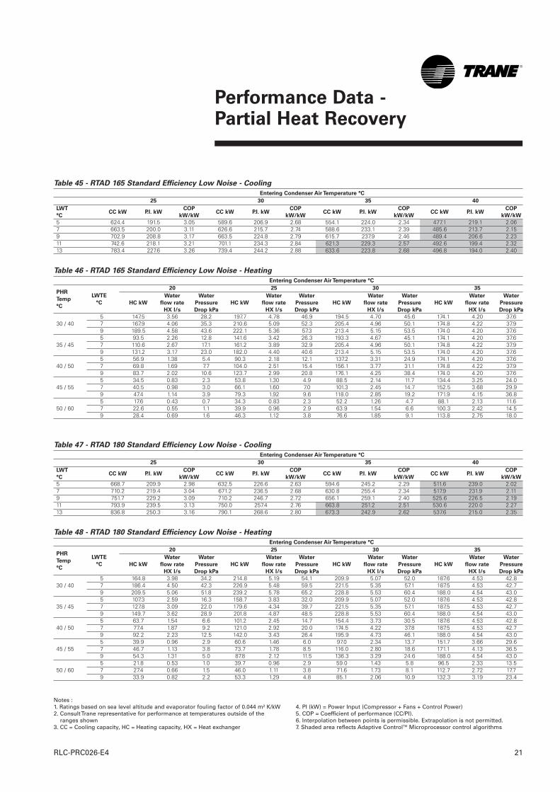
Table 45 - RTAD 165 Standard Efficiency Low Noise - Cooling
Entering Condenser Air Temperature °C
25 30 35 40
5 624.4 191.5 3.05 589.6 206.9 2.68 554.1 224.0 2.34 477.1 219.1 2.067 663.5 200.0 3.11 626.6 215.7 2.74 588.6 233.1 2.39 485.6 213.7 2.159 702.9 208.8 3.17 663.5 224.8 2.79 615.7 237.9 2.46 489.4 206.6 2.2311 742.6 218.1 3.21 701.1 234.3 2.84 621.3 229.3 2.57 492.6 199.4 2.3213 783.4 227.6 3.26 739.4 244.2 2.88 633.6 223.8 2.68 496.8 194.0 2.40
Table 46 - RTAD 165 Standard Efficiency Low Noise - Heating
Entering Condenser Air Temperature °C
20 25 30 35
5 147.5 3.56 28.2 197.7 4.78 46.9 194.5 4.70 45.6 174.1 4.20 37.630 / 40 7 167.9 4.06 35.3 210.6 5.09 52.3 205.4 4.96 50.1 174.8 4.22 37.9
9 189.5 4.58 43.6 222.1 5.36 57.3 213.4 5.15 53.5 174.0 4.20 37.65 93.5 2.26 12.8 141.6 3.42 26.3 193.3 4.67 45.1 174.1 4.20 37.6
35 / 45 7 110.6 2.67 17.1 161.2 3.89 32.9 205.4 4.96 50.1 174.8 4.22 37.99 131.2 3.17 23.0 182.0 4.40 40.6 213.4 5.15 53.5 174.0 4.20 37.65 56.9 1.38 5.4 90.3 2.18 12.1 137.2 3.31 24.9 174.1 4.20 37.6
40 / 50 7 69.8 1.69 7.7 104.0 2.51 15.4 156.1 3.77 31.1 174.8 4.22 37.99 83.7 2.02 10.6 123.7 2.99 20.8 176.1 4.25 38.4 174.0 4.20 37.65 34.5 0.83 2.3 53.8 1.30 4.9 88.5 2.14 11.7 134.4 3.25 24.0
45 / 55 7 40.5 0.98 3.0 66.1 1.60 7.0 101.3 2.45 14.7 152.5 3.68 29.99 47.4 1.14 3.9 79.3 1.92 9.6 118.0 2.85 19.2 171.9 4.15 36.85 17.6 0.43 0.7 34.3 0.83 2.3 52.2 1.26 4.7 88.1 2.13 11.6
50 / 60 7 22.6 0.55 1.1 39.9 0.96 2.9 63.9 1.54 6.6 100.3 2.42 14.59 28.4 0.69 1.6 46.3 1.12 3.8 76.6 1.85 9.1 113.8 2.75 18.0
LWT
°CCC kW P.I. kW
COP
kW/kWCC kW P.I. kW
COP
kW/kWCC kW P.I. kW
COP
kW/kWCC kW P.I. kW
COP
kW/kW
PHR
Temp
°C
LWTE
°C HC kW
Water
flow rate
HX l/s
Water
Pressure
Drop kPa
HC kW
Water
flow rate
HX l/s
Water
Pressure
Drop kPa
HC kW
Water
flow rate
HX l/s
Water
Pressure
Drop kPa
HC kW
Water
flow rate
HX l/s
Water
Pressure
Drop kPa
Table 47 - RTAD 180 Standard Efficiency Low Noise - Cooling
Entering Condenser Air Temperature °C
25 30 35 40
5 668.7 209.9 2.98 632.5 226.6 2.63 594.6 245.2 2.29 511.6 239.0 2.027 710.2 219.4 3.04 671.2 236.5 2.68 630.8 255.4 2.34 517.9 231.9 2.119 751.7 229.2 3.09 710.2 246.7 2.72 656.1 259.1 2.40 525.6 226.5 2.1911 793.9 239.5 3.13 750.0 257.4 2.76 663.8 251.2 2.51 530.6 220.0 2.2713 836.8 250.3 3.16 790.1 268.6 2.80 673.3 242.9 2.62 537.6 215.0 2.35
Table 48 - RTAD 180 Standard Efficiency Low Noise - Heating
Entering Condenser Air Temperature °C
20 25 30 35
5 164.8 3.98 34.2 214.8 5.19 54.1 209.9 5.07 52.0 187.6 4.53 42.830 / 40 7 186.4 4.50 42.3 226.9 5.48 59.5 221.5 5.35 57.1 187.5 4.53 42.7
9 209.5 5.06 51.8 239.2 5.78 65.2 228.8 5.53 60.4 188.0 4.54 43.05 107.3 2.59 16.3 158.7 3.83 32.0 209.9 5.07 52.0 187.6 4.53 42.8
35 / 45 7 127.8 3.09 22.0 179.6 4.34 39.7 221.5 5.35 57.1 187.5 4.53 42.79 149.7 3.62 28.9 201.8 4.87 48.5 228.8 5.53 60.4 188.0 4.54 43.05 63.7 1.54 6.6 101.2 2.45 14.7 154.4 3.73 30.5 187.6 4.53 42.8
40 / 50 7 77.4 1.87 9.2 121.0 2.92 20.0 174.5 4.22 37.8 187.5 4.53 42.79 92.2 2.23 12.5 142.0 3.43 26.4 195.9 4.73 46.1 188.0 4.54 43.05 39.9 0.96 2.9 60.6 1.46 6.0 97.0 2.34 13.7 151.7 3.66 29.6
45 / 55 7 46.7 1.13 3.8 73.7 1.78 8.5 116.0 2.80 18.6 171.1 4.13 36.59 54.3 1.31 5.0 87.8 2.12 11.5 136.3 3.29 24.6 188.0 4.54 43.05 21.8 0.53 1.0 39.7 0.96 2.9 59.0 1.43 5.8 96.5 2.33 13.5
50 / 60 7 27.4 0.66 1.5 46.0 1.11 3.8 71.6 1.73 8.1 112.7 2.72 17.79 33.9 0.82 2.2 53.3 1.29 4.8 85.1 2.06 10.9 132.3 3.19 23.4
LWT
°CCC kW P.I. kW
COP
kW/kWCC kW P.I. kW
COP
kW/kWCC kW P.I. kW
COP
kW/kWCC kW P.I. kW
COP
kW/kW
PHR
Temp
°C
LWTE
°C HC kW
Water
flow rate
HX l/s
Water
Pressure
Drop kPa
HC kW
Water
flow rate
HX l/s
Water
Pressure
Drop kPa
HC kW
Water
flow rate
HX l/s
Water
Pressure
Drop kPa
HC kW
Water
flow rate
HX l/s
Water
Pressure
Drop kPa
Notes :1. Ratings based on sea level altitude and evaporator fouling factor of 0.044 m² K/kW2. Consult Trane representative for performance at temperatures outside of the
ranges shown3. CC = Cooling capacity, HC = Heating capacity, HX = Heat exchanger
4. PI (kW) = Power Input (Compressor + Fans + Control Power)5. COP = Coefficient of performance (CC/PI).6. Interpolation between points is permissible. Extrapolation is not permitted.7. Shaded area reflects Adaptive ControlTM Microprocessor control algorithms
Performance Data - Partial Heat Recovery
RLC-PRC026-E422
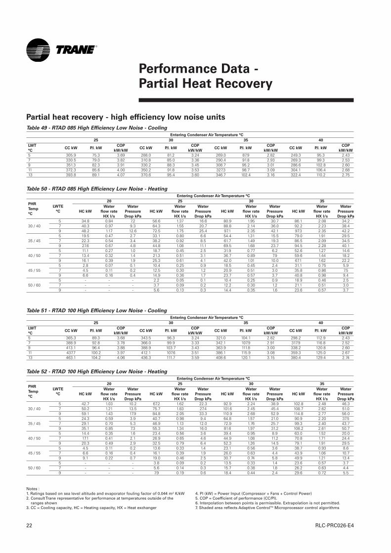
Table 49 - RTAD 085 High Efficiency Low Noise - Cooling
Entering Condenser Air Temperature °C
25 30 35 40
5 305.9 75.3 3.69 288.0 81.2 3.24 269.0 87.9 2.82 249.3 95.3 2.437 330.5 79.0 3.82 310.8 85.0 3.36 290.4 91.8 2.93 269.3 99.3 2.539 351.3 82.3 3.91 330.2 88.3 3.45 308.7 95.2 3.01 286.6 102.8 2.6011 372.3 85.6 4.00 350.2 91.8 3.53 327.3 98.7 3.09 304.1 106.4 2.6813 393.8 89.1 4.07 370.6 95.4 3.60 346.7 102.4 3.16 322.4 110.2 2.75
Table 50 - RTAD 085 High Efficiency Low Noise - Heating
Entering Condenser Air Temperature °C
20 25 30 35
5 34.8 0.84 7.2 56.6 1.37 16.6 80.9 1.95 30.7 86.1 2.08 34.230 / 40 7 40.3 0.97 9.3 64.3 1.55 20.7 88.8 2.14 36.0 92.2 2.23 38.4
9 48.2 1.17 12.6 72.5 1.75 25.4 97.1 2.35 42.1 97.3 2.35 42.25 19.5 0.47 2.7 33.1 0.80 6.6 54.4 1.31 15.5 79.0 1.91 29.5
35 / 45 7 22.3 0.54 3.4 38.2 0.92 8.5 61.7 1.49 19.3 86.5 2.09 34.59 27.6 0.67 4.8 44.8 1.08 11.1 69.5 1.68 23.7 94.5 2.28 40.15 11.1 0.27 1.0 18.7 0.45 2.5 31.9 0.77 6.2 52.6 1.27 14.6
40 / 50 7 13.4 0.32 1.4 21.3 0.51 3.1 36.7 0.89 7.9 59.6 1.44 18.29 16.1 0.39 1.9 25.3 0.61 4.1 42.0 1.01 10.0 67.1 1.62 22.25 2.8 0.07 0.1 10.4 0.25 0.9 18.5 0.45 2.4 31.1 0.75 5.9
45 / 55 7 4.5 0.11 0.2 12.5 0.30 1.2 20.9 0.51 3.0 35.8 0.86 7.59 6.6 0.16 0.4 14.9 0.36 1.7 23.7 0.57 3.7 40.8 0.98 9.45 - - - 2.2 0.05 0.1 10.4 0.25 0.9 18.9 0.46 2.5
50 / 60 7 - - - 3.7 0.09 0.2 12.2 0.30 1.2 21.1 0.51 3.09 - - - 5.6 0.13 0.3 14.4 0.35 1.6 23.6 0.57 3.7
LWT
°CCC kW P.I. kW
COP
kW/kWCC kW P.I. kW
COP
kW/kWCC kW P.I. kW
COP
kW/kWCC kW P.I. kW
COP
kW/kW
PHR
Temp
°C
LWTE
°C HC kW
Water
flow rate
HX l/s
Water
Pressure
Drop kPa
HC kW
Water
flow rate
HX l/s
Water
Pressure
Drop kPa
HC kW
Water
flow rate
HX l/s
Water
Pressure
Drop kPa
HC kW
Water
flow rate
HX l/s
Water
Pressure
Drop kPa
Table 51 - RTAD 100 High Efficiency Low Noise - Cooling
Entering Condenser Air Temperature °C
25 30 35 40
5 365.3 89.3 3.68 343.5 96.3 3.24 321.0 104.1 2.82 298.2 112.9 2.437 388.9 92.8 3.78 366.0 99.9 3.33 342.1 107.9 2.91 317.9 116.8 2.529 413.1 96.4 3.88 388.9 103.7 3.43 363.9 111.8 3.00 338.2 120.8 2.6011 437.7 100.2 3.97 412.1 107.6 3.51 386.1 115.9 3.08 359.3 125.0 2.6713 463.1 104.2 4.06 436.3 111.7 3.59 408.6 120.1 3.15 380.4 129.4 2.74
Table 52 - RTAD 100 High Efficiency Low Noise - Heating
Entering Condenser Air Temperature °C
20 25 30 35
5 42.7 1.03 10.2 67.2 1.62 22.3 92.9 2.24 38.9 102.8 2.48 46.330 / 40 7 50.2 1.21 13.5 75.7 1.83 27.4 101.6 2.45 45.4 108.7 2.62 51.0
9 59.1 1.43 17.9 84.8 2.05 33.3 110.9 2.68 52.9 114.8 2.77 56.05 24.3 0.59 3.9 40.7 0.98 9.4 64.8 1.57 21.0 90.9 2.20 37.5
35 / 45 7 29.1 0.70 5.3 46.9 1.13 12.0 72.9 1.76 25.7 99.3 2.40 43.79 35.1 0.85 7.3 55.3 1.34 16.0 81.6 1.97 31.2 108.2 2.61 50.75 14.4 0.35 1.6 23.4 0.56 3.6 39.4 0.95 8.9 63.0 1.52 20.0
40 / 50 7 17.1 0.41 2.1 26.9 0.65 4.6 44.9 1.08 11.2 70.8 1.71 24.49 20.3 0.49 2.9 32.5 0.79 6.4 52.3 1.26 14.5 79.1 1.91 29.55 4.5 0.11 0.2 13.6 0.33 1.4 23.1 0.56 3.6 38.7 0.93 8.6
45 / 55 7 6.6 0.16 0.4 16.1 0.39 1.9 26.0 0.63 4.4 43.9 1.06 10.79 9.1 0.22 0.7 19.0 0.46 2.5 30.7 0.74 5.8 49.9 1.21 13.45 - - - 3.8 0.09 0.2 13.5 0.33 1.4 23.6 0.57 3.7
50 / 60 7 - - - 5.6 0.14 0.3 15.7 0.38 1.8 26.2 0.63 4.49 - - - 7.9 0.19 0.6 18.4 0.44 2.4 29.6 0.72 5.5
LWT
°CCC kW P.I. kW
COP
kW/kWCC kW P.I. kW
COP
kW/kWCC kW P.I. kW
COP
kW/kWCC kW P.I. kW
COP
kW/kW
PHR
Temp
°C
LWTE
°C HC kW
Water
flow rate
HX l/s
Water
Pressure
Drop kPa
HC kW
Water
flow rate
HX l/s
Water
Pressure
Drop kPa
HC kW
Water
flow rate
HX l/s
Water
Pressure
Drop kPa
HC kW
Water
flow rate
HX l/s
Water
Pressure
Drop kPa
Notes :1. Ratings based on sea level altitude and evaporator fouling factor of 0.044 m² K/kW2. Consult Trane representative for performance at temperatures outside of the
ranges shown3. CC = Cooling capacity, HC = Heating capacity, HX = Heat exchanger
4. PI (kW) = Power Input (Compressor + Fans + Control Power)5. COP = Coefficient of performance (CC/PI).6. Interpolation between points is permissible. Extrapolation is not permitted.7. Shaded area reflects Adaptive ControlTM Microprocessor control algorithms
Partial heat recovery - high efficiency low noise units

Performance Data - Partial Heat Recovery
23RLC-PRC026-E4
Table 53 - RTAD 115 High Efficiency Low Noise - Cooling
Entering Condenser Air Temperature °C
25 30 35 40
5 434.2 116.3 3.44 408.9 126.0 3.01 383.2 136.8 2.62 356.5 148.8 2.257 463.1 120.9 3.54 436.3 130.8 3.11 408.9 141.8 2.70 380.8 154.0 2.339 492.6 125.8 3.63 464.5 135.8 3.19 435.3 147.0 2.78 405.4 159.4 2.4011 522.8 130.9 3.72 492.9 141.1 3.27 462.0 152.5 2.85 421.9 160.2 2.4913 553.8 136.2 3.80 522.1 146.6 3.34 489.8 158.2 2.92 427.6 154.4 2.61
Table 54 - RTAD 115 High Efficiency Low Noise - Heating
Entering Condenser Air Temperature °C
20 25 30 35
5 70.6 1.70 16.6 102.3 2.47 31.2 130.0 3.14 46.9 126.3 3.05 44.730 / 40 7 82.0 1.98 21.4 114.0 2.75 37.5 137.7 3.33 51.7 133.7 3.23 49.2
9 94.2 2.28 27.1 126.5 3.06 44.8 145.6 3.52 56.8 141.2 3.41 53.95 42.4 1.02 7.0 67.2 1.62 15.3 99.8 2.41 29.9 126.3 3.05 44.7
35 / 45 7 50.0 1.21 9.2 78.2 1.89 19.8 111.0 2.68 35.9 133.7 3.23 49.29 58.3 1.41 12.0 89.9 2.17 25.1 123.0 2.97 42.7 141.2 3.41 53.95 26.0 0.63 3.0 40.5 0.98 6.5 64.8 1.57 14.4 98.0 2.37 29.0
40 / 50 7 29.8 0.72 3.8 47.7 1.15 8.5 75.3 1.82 18.6 108.8 2.63 34.79 34.2 0.83 4.9 55.7 1.34 11.1 86.6 2.09 23.5 120.4 2.91 41.15 14.4 0.35 1.1 25.5 0.62 2.9 39.5 0.95 6.2 63.3 1.53 13.8
45 / 55 7 17.5 0.42 1.6 29.1 0.70 3.7 46.4 1.12 8.1 73.3 1.77 17.79 21.1 0.51 2.1 33.2 0.80 4.6 54.0 1.30 10.5 84.1 2.03 22.45 2.8 0.07 0.1 14.1 0.34 1.1 26.0 0.63 3.0 39.3 0.95 6.1
50 / 60 7 5.2 0.12 0.2 16.9 0.41 1.5 29.3 0.71 3.7 45.9 1.11 8.09 8.0 0.19 0.4 20.3 0.49 2.0 33.2 0.80 4.6 53.1 1.28 10.2
LWT
°CCC kW P.I. kW
COP
kW/kWCC kW P.I. kW
COP
kW/kWCC kW P.I. kW
COP
kW/kWCC kW P.I. kW
COP
kW/kW
PHR
Temp
°C
LWTE
°C HC kW
Water
flow rate
HX l/s
Water
Pressure
Drop kPa
HC kW
Water
flow rate
HX l/s
Water
Pressure
Drop kPa
HC kW
Water
flow rate
HX l/s
Water
Pressure
Drop kPa
HC kW
Water
flow rate
HX l/s
Water
Pressure
Drop kPa
Table 55 - RTAD 125 High Efficiency Low Noise - Cooling
Entering Condenser Air Temperature °C
25 30 35 40
5 506.7 142.8 3.27 477.5 154.8 2.86 447.2 168.0 2.49 416.7 182.6 2.147 539.4 148.5 3.36 508.4 160.7 2.94 476.8 174.2 2.56 444.1 189.0 2.219 572.8 154.5 3.44 540.1 166.9 3.02 506.7 180.6 2.63 448.6 182.0 2.3211 607.2 160.8 3.51 572.8 173.4 3.09 537.2 187.2 2.70 456.7 176.6 2.4313 642.4 167.3 3.58 606.2 180.0 3.16 568.5 194.1 2.76 462.0 169.8 2.55
Table 56 - RTAD 125 High Efficiency Low Noise - Heating
Entering Condenser Air Temperature °C
20 25 30 35
5 91.9 2.22 26.0 125.9 3.04 44.4 153.8 3.72 62.4 149.8 3.62 59.730 / 40 7 105.0 2.54 32.6 139.2 3.36 52.7 162.7 3.93 68.7 158.3 3.82 65.5
9 118.9 2.87 40.3 153.5 3.71 62.2 171.8 4.15 75.3 157.7 3.81 65.15 57.8 1.40 11.8 88.7 2.14 24.5 123.5 2.98 43.0 149.8 3.62 59.7
35 / 45 7 66.8 1.61 15.1 101.2 2.44 30.6 136.4 3.29 50.8 158.3 3.82 65.59 79.9 1.93 20.5 114.6 2.77 37.8 150.2 3.63 59.9 157.7 3.81 65.15 35.5 0.86 5.2 56.2 1.36 11.3 86.5 2.09 23.5 122.2 2.95 42.2
40 / 50 7 40.5 0.98 6.5 64.7 1.56 14.3 98.5 2.38 29.3 134.6 3.25 49.79 49.4 1.19 9.0 75.7 1.83 18.7 111.5 2.69 36.1 147.8 3.57 58.35 21.9 0.53 2.3 35.4 0.86 5.2 55.5 1.34 11.0 85.3 2.06 22.9
45 / 55 7 26.0 0.63 3.0 40.1 0.97 6.3 63.7 1.54 13.9 96.9 2.34 28.59 30.7 0.74 4.0 47.0 1.13 8.3 72.7 1.76 17.5 109.2 2.64 34.95 8.2 0.20 0.4 21.9 0.53 2.3 36.3 0.88 5.4 55.8 1.35 11.1
50 / 60 7 11.5 0.28 0.8 25.7 0.62 3.0 40.6 0.98 6.5 63.6 1.54 13.99 15.3 0.37 1.2 30.1 0.73 3.9 45.7 1.10 7.9 72.1 1.74 17.2
LWT
°CCC kW P.I. kW
COP
kW/kWCC kW P.I. kW
COP
kW/kWCC kW P.I. kW
COP
kW/kWCC kW P.I. kW
COP
kW/kW
PHR
Temp
°C
LWTE
°C HC kW
Water
flow rate
HX l/s
Water
Pressure
Drop kPa
HC kW
Water
flow rate
HX l/s
Water
Pressure
Drop kPa
HC kW
Water
flow rate
HX l/s
Water
Pressure
Drop kPa
HC kW
Water
flow rate
HX l/s
Water
Pressure
Drop kPa
Notes :1. Ratings based on sea level altitude and evaporator fouling factor of 0.044 m² K/kW2. Consult Trane representative for performance at temperatures outside of the
ranges shown3. CC = Cooling capacity, HC = Heating capacity, HX = Heat exchanger
4. PI (kW) = Power Input (Compressor + Fans + Control Power)5. COP = Coefficient of performance (CC/PI).6. Interpolation between points is permissible. Extrapolation is not permitted.7. Shaded area reflects Adaptive ControlTM Microprocessor control algorithms
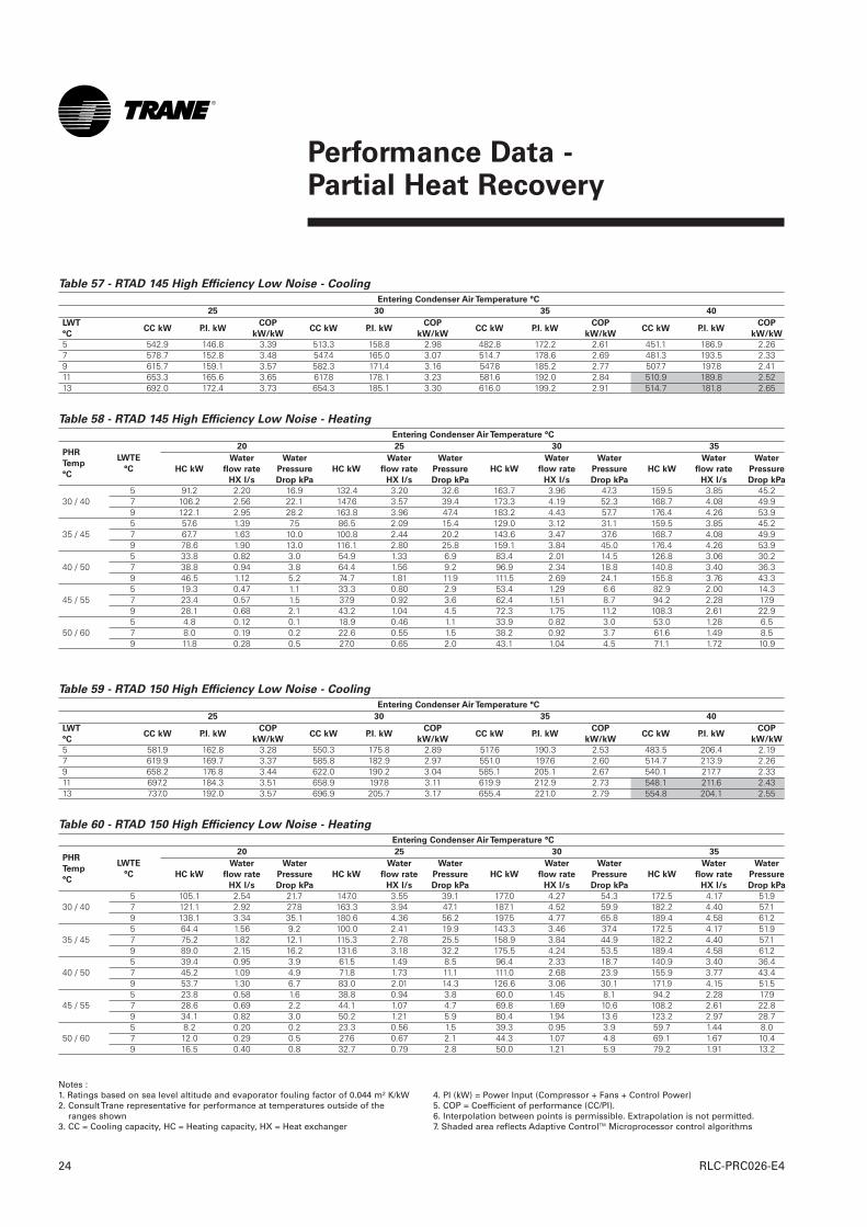
Performance Data - Partial Heat Recovery
RLC-PRC026-E424
Table 57 - RTAD 145 High Efficiency Low Noise - Cooling
Entering Condenser Air Temperature °C
25 30 35 40
5 542.9 146.8 3.39 513.3 158.8 2.98 482.8 172.2 2.61 451.1 186.9 2.267 578.7 152.8 3.48 547.4 165.0 3.07 514.7 178.6 2.69 481.3 193.5 2.339 615.7 159.1 3.57 582.3 171.4 3.16 547.8 185.2 2.77 507.7 197.8 2.4111 653.3 165.6 3.65 617.8 178.1 3.23 581.6 192.0 2.84 510.9 189.8 2.5213 692.0 172.4 3.73 654.3 185.1 3.30 616.0 199.2 2.91 514.7 181.8 2.65
Table 58 - RTAD 145 High Efficiency Low Noise - Heating
Entering Condenser Air Temperature °C
20 25 30 35
5 91.2 2.20 16.9 132.4 3.20 32.6 163.7 3.96 47.3 159.5 3.85 45.230 / 40 7 106.2 2.56 22.1 147.6 3.57 39.4 173.3 4.19 52.3 168.7 4.08 49.9
9 122.1 2.95 28.2 163.8 3.96 47.4 183.2 4.43 57.7 176.4 4.26 53.95 57.6 1.39 7.5 86.5 2.09 15.4 129.0 3.12 31.1 159.5 3.85 45.2
35 / 45 7 67.7 1.63 10.0 100.8 2.44 20.2 143.6 3.47 37.6 168.7 4.08 49.99 78.6 1.90 13.0 116.1 2.80 25.8 159.1 3.84 45.0 176.4 4.26 53.95 33.8 0.82 3.0 54.9 1.33 6.9 83.4 2.01 14.5 126.8 3.06 30.2
40 / 50 7 38.8 0.94 3.8 64.4 1.56 9.2 96.9 2.34 18.8 140.8 3.40 36.39 46.5 1.12 5.2 74.7 1.81 11.9 111.5 2.69 24.1 155.8 3.76 43.35 19.3 0.47 1.1 33.3 0.80 2.9 53.4 1.29 6.6 82.9 2.00 14.3
45 / 55 7 23.4 0.57 1.5 37.9 0.92 3.6 62.4 1.51 8.7 94.2 2.28 17.99 28.1 0.68 2.1 43.2 1.04 4.5 72.3 1.75 11.2 108.3 2.61 22.95 4.8 0.12 0.1 18.9 0.46 1.1 33.9 0.82 3.0 53.0 1.28 6.5
50 / 60 7 8.0 0.19 0.2 22.6 0.55 1.5 38.2 0.92 3.7 61.6 1.49 8.59 11.8 0.28 0.5 27.0 0.65 2.0 43.1 1.04 4.5 71.1 1.72 10.9
LWT
°CCC kW P.I. kW
COP
kW/kWCC kW P.I. kW
COP
kW/kWCC kW P.I. kW
COP
kW/kWCC kW P.I. kW
COP
kW/kW
PHR
Temp
°C
LWTE
°C HC kW
Water
flow rate
HX l/s
Water
Pressure
Drop kPa
HC kW
Water
flow rate
HX l/s
Water
Pressure
Drop kPa
HC kW
Water
flow rate
HX l/s
Water
Pressure
Drop kPa
HC kW
Water
flow rate
HX l/s
Water
Pressure
Drop kPa
Table 59 - RTAD 150 High Efficiency Low Noise - Cooling
Entering Condenser Air Temperature °C
25 30 35 40
5 581.9 162.8 3.28 550.3 175.8 2.89 517.6 190.3 2.53 483.5 206.4 2.197 619.9 169.7 3.37 585.8 182.9 2.97 551.0 197.6 2.60 514.7 213.9 2.269 658.2 176.8 3.44 622.0 190.2 3.04 585.1 205.1 2.67 540.1 217.7 2.3311 697.2 184.3 3.51 658.9 197.8 3.11 619.9 212.9 2.73 548.1 211.6 2.4313 737.0 192.0 3.57 696.9 205.7 3.17 655.4 221.0 2.79 554.8 204.1 2.55
Table 60 - RTAD 150 High Efficiency Low Noise - Heating
Entering Condenser Air Temperature °C
20 25 30 35
5 105.1 2.54 21.7 147.0 3.55 39.1 177.0 4.27 54.3 172.5 4.17 51.930 / 40 7 121.1 2.92 27.8 163.3 3.94 47.1 187.1 4.52 59.9 182.2 4.40 57.1
9 138.1 3.34 35.1 180.6 4.36 56.2 197.5 4.77 65.8 189.4 4.58 61.25 64.4 1.56 9.2 100.0 2.41 19.9 143.3 3.46 37.4 172.5 4.17 51.9
35 / 45 7 75.2 1.82 12.1 115.3 2.78 25.5 158.9 3.84 44.9 182.2 4.40 57.19 89.0 2.15 16.2 131.6 3.18 32.2 175.5 4.24 53.5 189.4 4.58 61.25 39.4 0.95 3.9 61.5 1.49 8.5 96.4 2.33 18.7 140.9 3.40 36.4
40 / 50 7 45.2 1.09 4.9 71.8 1.73 11.1 111.0 2.68 23.9 155.9 3.77 43.49 53.7 1.30 6.7 83.0 2.01 14.3 126.6 3.06 30.1 171.9 4.15 51.55 23.8 0.58 1.6 38.8 0.94 3.8 60.0 1.45 8.1 94.2 2.28 17.9
45 / 55 7 28.6 0.69 2.2 44.1 1.07 4.7 69.8 1.69 10.6 108.2 2.61 22.89 34.1 0.82 3.0 50.2 1.21 5.9 80.4 1.94 13.6 123.2 2.97 28.75 8.2 0.20 0.2 23.3 0.56 1.5 39.3 0.95 3.9 59.7 1.44 8.0
50 / 60 7 12.0 0.29 0.5 27.6 0.67 2.1 44.3 1.07 4.8 69.1 1.67 10.49 16.5 0.40 0.8 32.7 0.79 2.8 50.0 1.21 5.9 79.2 1.91 13.2
LWT
°CCC kW P.I. kW
COP
kW/kWCC kW P.I. kW
COP
kW/kWCC kW P.I. kW
COP
kW/kWCC kW P.I. kW
COP
kW/kW
PHR
Temp
°C
LWTE
°C HC kW
Water
flow rate
HX l/s
Water
Pressure
Drop kPa
HC kW
Water
flow rate
HX l/s
Water
Pressure
Drop kPa
HC kW
Water
flow rate
HX l/s
Water
Pressure
Drop kPa
HC kW
Water
flow rate
HX l/s
Water
Pressure
Drop kPa
Notes :1. Ratings based on sea level altitude and evaporator fouling factor of 0.044 m² K/kW2. Consult Trane representative for performance at temperatures outside of the
ranges shown3. CC = Cooling capacity, HC = Heating capacity, HX = Heat exchanger
4. PI (kW) = Power Input (Compressor + Fans + Control Power)5. COP = Coefficient of performance (CC/PI).6. Interpolation between points is permissible. Extrapolation is not permitted.7. Shaded area reflects Adaptive ControlTM Microprocessor control algorithms
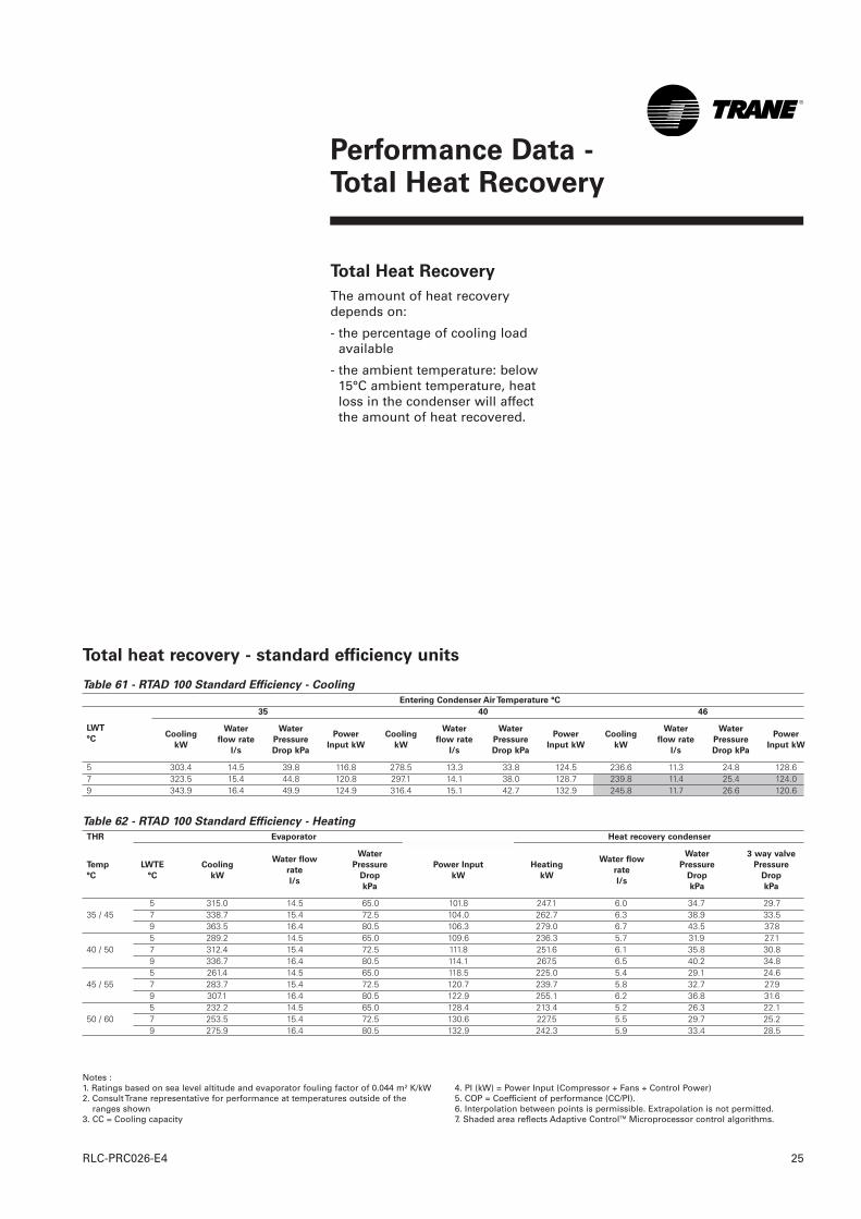
Performance Data - Total Heat Recovery
25RLC-PRC026-E4
Total Heat Recovery
The amount of heat recoverydepends on:
- the percentage of cooling loadavailable
- the ambient temperature: below15°C ambient temperature, heatloss in the condenser will affectthe amount of heat recovered.
Table 61 - RTAD 100 Standard Efficiency - Cooling
Entering Condenser Air Temperature °C
35 40 46
5 303.4 14.5 39.8 116.8 278.5 13.3 33.8 124.5 236.6 11.3 24.8 128.67 323.5 15.4 44.8 120.8 297.1 14.1 38.0 128.7 239.8 11.4 25.4 124.09 343.9 16.4 49.9 124.9 316.4 15.1 42.7 132.9 245.8 11.7 26.6 120.6
Table 62 - RTAD 100 Standard Efficiency - Heating
THR Evaporator Heat recovery condenser
5 315.0 14.5 65.0 101.8 247.1 6.0 34.7 29.735 / 45 7 338.7 15.4 72.5 104.0 262.7 6.3 38.9 33.5
9 363.5 16.4 80.5 106.3 279.0 6.7 43.5 37.85 289.2 14.5 65.0 109.6 236.3 5.7 31.9 27.1
40 / 50 7 312.4 15.4 72.5 111.8 251.6 6.1 35.8 30.89 336.7 16.4 80.5 114.1 267.5 6.5 40.2 34.85 261.4 14.5 65.0 118.5 225.0 5.4 29.1 24.6
45 / 55 7 283.7 15.4 72.5 120.7 239.7 5.8 32.7 27.99 307.1 16.4 80.5 122.9 255.1 6.2 36.8 31.65 232.2 14.5 65.0 128.4 213.4 5.2 26.3 22.1
50 / 60 7 253.5 15.4 72.5 130.6 227.5 5.5 29.7 25.29 275.9 16.4 80.5 132.9 242.3 5.9 33.4 28.5
LWT
°CCooling
kW
Water
flow rate
l/s
Water
Pressure
Drop kPa
Power
Input kW
Cooling
kW
Water
flow rate
l/s
Water
Pressure
Drop kPa
Power
Input kW
Cooling
kW
Water
flow rate
l/s
Water
Pressure
Drop kPa
Power
Input kW
Temp
°C
LWTE
°C
Cooling
kW
Water flow
rate
l/s
Water
Pressure
Drop
kPa
Power Input
kW
Heating
kW
Water flow
rate
l/s
Water
Pressure
Drop
kPa
3 way valve
Pressure
Drop
kPa
Total heat recovery - standard efficiency units
Notes :1. Ratings based on sea level altitude and evaporator fouling factor of 0.044 m² K/kW2. Consult Trane representative for performance at temperatures outside of the
ranges shown3. CC = Cooling capacity
4. PI (kW) = Power Input (Compressor + Fans + Control Power)5. COP = Coefficient of performance (CC/PI).6. Interpolation between points is permissible. Extrapolation is not permitted.7. Shaded area reflects Adaptive ControlTM Microprocessor control algorithms.
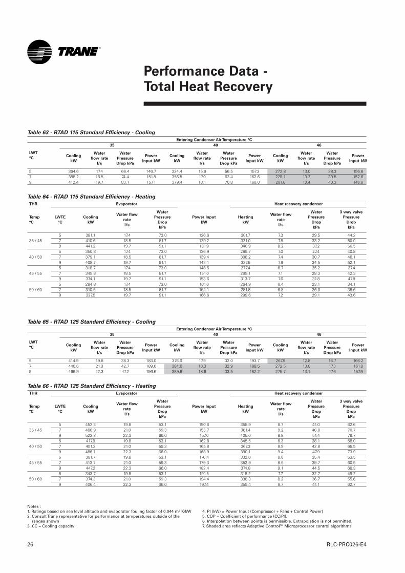
Performance Data - Total Heat Recovery
RLC-PRC026-E426
Notes :1. Ratings based on sea level altitude and evaporator fouling factor of 0.044 m² K/kW2. Consult Trane representative for performance at temperatures outside of the
ranges shown3. CC = Cooling capacity
4. PI (kW) = Power Input (Compressor + Fans + Control Power)5. COP = Coefficient of performance (CC/PI).6. Interpolation between points is permissible. Extrapolation is not permitted.7. Shaded area reflects Adaptive ControlTM Microprocessor control algorithms.
Table 63 - RTAD 115 Standard Efficiency - Cooling
Entering Condenser Air Temperature °C
35 40 46
5 364.6 17.4 66.4 146.7 334.4 15.9 56.5 157.3 272.8 13.0 38.3 156.67 388.2 18.5 74.4 151.8 356.5 17.0 63.4 162.6 278.1 13.2 39.5 152.69 412.4 19.7 83.1 157.1 379.4 18.1 70.8 168.0 281.6 13.4 40.3 148.8
Table 64 - RTAD 115 Standard Efficiency - Heating
THR Evaporator Heat recovery condenser
5 381.1 17.4 73.0 126.6 301.7 7.3 29.5 44.235 / 45 7 410.6 18.5 81.7 129.2 321.0 7.8 33.2 50.0
9 441.2 19.7 91.1 131.9 340.9 8.2 37.2 56.55 350.8 17.4 73.0 136.9 289.7 7.0 27.4 40.8
40 / 50 7 379.1 18.5 81.7 139.4 308.2 7.4 30.7 46.19 408.7 19.7 91.1 142.1 327.5 7.9 34.5 52.15 318.7 17.4 73.0 148.5 277.4 6.7 25.2 37.4
45 / 55 7 345.8 18.5 81.7 151.0 295.1 7.1 28.3 42.39 374.1 19.7 91.1 153.6 313.7 7.6 31.8 47.85 284.8 17.4 73.0 161.6 264.9 6.4 23.1 34.1
50 / 60 7 310.5 18.5 81.7 164.1 281.8 6.8 26.0 38.69 337.5 19.7 91.1 166.6 299.6 7.2 29.1 43.6
LWT
°CCooling
kW
Water
flow rate
l/s
Water
Pressure
Drop kPa
Power
Input kW
Cooling
kW
Water
flow rate
l/s
Water
Pressure
Drop kPa
Power
Input kW
Cooling
kW
Water
flow rate
l/s
Water
Pressure
Drop kPa
Power
Input kW
Temp
°C
LWTE
°C
Cooling
kW
Water flow
rate
l/s
Water
Pressure
Drop
kPa
Power Input
kW
Heating
kW
Water flow
rate
l/s
Water
Pressure
Drop
kPa
3 way valve
Pressure
Drop
kPa
Table 65 - RTAD 125 Standard Efficiency - Cooling
Entering Condenser Air Temperature °C
35 40 46
5 414.9 19.8 38.3 183.0 376.6 17.9 32.0 193.7 267.9 12.8 16.7 166.27 440.6 21.0 42.7 189.6 384.0 18.3 32.9 188.5 272.5 13.0 17.3 161.89 466.9 22.3 47.2 196.6 389.6 18.6 33.5 182.2 275.7 13.1 17.6 157.9
Table 66 - RTAD 125 Standard Efficiency - Heating
THR Evaporator Heat recovery condenser
5 452.3 19.8 53.1 150.6 358.9 8.7 41.0 62.635 / 45 7 486.9 21.0 59.3 153.7 381.4 9.2 46.0 70.7
9 522.8 22.3 66.0 157.0 405.0 9.8 51.4 79.75 417.9 19.8 53.1 162.8 345.5 8.3 38.1 58.0
40 / 50 7 451.2 21.0 59.3 165.8 367.3 8.9 42.8 65.59 486.1 22.3 66.0 168.9 390.1 9.4 47.9 73.95 381.7 19.8 53.1 176.4 332.0 8.0 35.4 53.5
45 / 55 7 413.7 21.0 59.3 179.3 352.9 8.5 39.7 60.59 447.2 22.3 66.0 182.4 374.8 9.1 44.5 68.35 343.7 19.8 53.1 191.5 318.2 7.7 32.7 49.2
50 / 60 7 374.3 21.0 59.3 194.4 338.3 8.2 36.7 55.69 406.4 22.3 66.0 197.4 359.4 8.7 41.1 62.7
LWT
°CCooling
kW
Water
flow rate
l/s
Water
Pressure
Drop kPa
Power
Input kW
Cooling
kW
Water
flow rate
l/s
Water
Pressure
Drop kPa
Power
Input kW
Cooling
kW
Water
flow rate
l/s
Water
Pressure
Drop kPa
Power
Input kW
Temp
°C
LWTE
°C
Cooling
kW
Water flow
rate
l/s
Water
Pressure
Drop
kPa
Power Input
kW
Heating
kW
Water flow
rate
l/s
Water
Pressure
Drop
kPa
3 way valve
Pressure
Drop
kPa
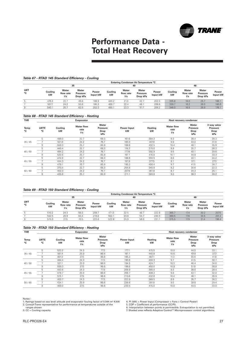
Performance Data - Total Heat Recovery
27RLC-PRC026-E4
Table 67 - RTAD 145 Standard Efficiency - Cooling
Entering Condenser Air Temperature °C
35 40 46
5 476.4 22.7 49.6 188.9 440.2 21.0 42.7 202.0 335.8 16.0 25.7 186.17 507.7 24.2 55.6 195.3 469.7 22.4 48.1 208.6 339.7 16.2 26.0 180.69 540.1 25.7 62.5 202.0 489.1 23.3 51.7 209.2 346.0 16.5 26.9 176.1
Table 68 - RTAD 145 Standard Efficiency - Heating
THR Evaporator Heat recovery condenser
5 486.0 22.7 68.3 161.6 384.3 9.3 38.4 28.335 / 45 7 521.9 24.2 76.7 165.0 407.9 9.9 43.0 31.9
9 559.3 25.7 85.9 168.6 432.5 10.4 48.1 35.95 449.4 22.7 68.3 174.3 370.0 8.9 35.7 26.3
40 / 50 7 484.2 24.2 76.7 177.6 392.9 9.5 40.1 29.69 520.6 25.7 85.9 181.1 416.8 10.1 44.8 33.35 410.9 22.7 68.3 188.6 355.5 8.6 33.1 24.2
45 / 55 7 444.3 24.2 76.7 191.9 377.5 9.1 37.1 27.39 479.1 25.7 85.9 195.3 400.4 9.7 41.5 30.75 370.4 22.7 68.3 204.6 340.8 8.2 30.6 22.3
50 / 60 7 402.3 24.2 76.7 207.8 361.8 8.7 34.3 25.19 435.6 25.7 85.9 211.1 383.8 9.3 38.3 28.2
LWT
°CCooling
kW
Water
flow rate
l/s
Water
Pressure
Drop kPa
Power
Input kW
Cooling
kW
Water
flow rate
l/s
Water
Pressure
Drop kPa
Power
Input kW
Cooling
kW
Water
flow rate
l/s
Water
Pressure
Drop kPa
Power
Input kW
Temp
°C
LWTE
°C
Cooling
kW
Water flow
rate
l/s
Water
Pressure
Drop
kPa
Power Input
kW
Heating
kW
Water flow
rate
l/s
Water
Pressure
Drop
kPa
3 way valve
Pressure
Drop
kPa
Notes :1. Ratings based on sea level altitude and evaporator fouling factor of 0.044 m² K/kW2. Consult Trane representative for performance at temperatures outside of the
ranges shown3. CC = Cooling capacity
4. PI (kW) = Power Input (Compressor + Fans + Control Power)5. COP = Coefficient of performance (CC/PI).6. Interpolation between points is permissible. Extrapolation is not permitted.7. Shaded area reflects Adaptive ControlTM Microprocessor control algorithms.
Table 69 - RTAD 150 Standard Efficiency - Cooling
Entering Condenser Air Temperature °C
35 40 46
5 510.2 24.3 56.5 208.7 471.5 22.5 48.7 222.8 365.7 17.4 30.2 207.57 542.5 25.9 63.4 216.0 502.1 23.9 54.7 230.3 369.5 17.6 30.5 201.49 575.9 27.5 70.5 223.6 522.8 24.9 58.6 231.7 375.5 17.9 31.4 196.4
Table 70 - RTAD 150 Standard Efficiency - Heating
THR Evaporator Heat recovery condenser
5 523.2 24.3 77.3 177.1 415.5 10.0 44.5 33.135 / 45 7 561.4 25.9 86.6 181.1 440.8 10.6 49.8 37.3
9 601.0 27.5 96.6 185.3 467.1 11.3 55.6 41.85 484.4 24.3 77.3 190.6 400.3 9.7 41.5 30.7
40 / 50 7 521.1 25.9 86.6 194.5 424.7 10.3 46.4 34.69 559.3 27.5 96.6 198.6 450.0 10.9 51.8 38.85 443.6 24.3 77.3 205.9 385.0 9.3 38.5 28.4
45 / 55 7 478.7 25.9 86.6 209.7 408.3 9.9 43.1 32.09 515.1 27.5 96.6 213.6 432.6 10.4 48.1 35.95 400.7 24.3 77.3 222.9 369.5 8.9 35.7 26.2
50 / 60 7 434.1 25.9 86.6 226.6 391.8 9.5 39.8 29.49 469.0 27.5 96.6 230.5 415.0 10.0 44.5 33.0
LWT
°CCooling
kW
Water
flow rate
l/s
Water
Pressure
Drop kPa
Power
Input kW
Cooling
kW
Water
flow rate
l/s
Water
Pressure
Drop kPa
Power
Input kW
Cooling
kW
Water
flow rate
l/s
Water
Pressure
Drop kPa
Power
Input kW
Temp
°C
LWTE
°C
Cooling
kW
Water flow
rate
l/s
Water
Pressure
Drop
kPa
Power Input
kW
Heating
kW
Water flow
rate
l/s
Water
Pressure
Drop
kPa
3 way valve
Pressure
Drop
kPa

Performance Data - Total Heat Recovery
RLC-PRC026-E428
Table 71 - RTAD 165 Standard Efficiency - Cooling
Entering Condenser Air Temperature °C
35 40 46
5 - - - - 521.4 24.8 47.2 236.3 412.8 19.7 30.5 224.17 596.7 28.4 60.7 229.0 555.9 26.5 52.9 244.3 417.0 19.9 30.8 217.89 634.3 30.2 67.8 237.2 586.1 27.9 58.3 249.9 421.2 20.1 31.1 211.4
Table 72 - RTAD 165 Standard Efficiency - Heating
THR Evaporator Heat recovery condenser
5 - - - - - - - -35 / 45 7 605.3 28.4 32.6 195.1 475.2 11.5 44.1 43.3
9 648.1 30.2 36.2 199.7 503.6 12.2 49.3 48.65 - - - - - - - -
40 / 50 7 564.5 28.4 32.6 209.7 459.4 11.1 41.4 40.59 605.9 30.2 36.2 214.1 486.9 11.8 46.2 45.55 - - - - - - - -
45 / 55 7 521.1 28.4 32.6 226.1 443.3 10.7 38.7 37.79 560.8 30.2 36.2 230.5 469.7 11.3 43.2 42.35 - - - - - - - -
50 / 60 7 475.5 28.4 32.6 244.5 426.9 10.3 36.0 35.09 513.4 30.2 36.2 248.9 452.3 10.9 40.2 39.2
LWT
°CCooling
kW
Water
flow rate
l/s
Water
Pressure
Drop kPa
Power
Input kW
Cooling
kW
Water
flow rate
l/s
Water
Pressure
Drop kPa
Power
Input kW
Cooling
kW
Water
flow rate
l/s
Water
Pressure
Drop kPa
Power
Input kW
Temp
°C
LWTE
°C
Cooling
kW
Water flow
rate
l/s
Water
Pressure
Drop
kPa
Power Input
kW
Heating
kW
Water flow
rate
l/s
Water
Pressure
Drop
kPa
3 way valve
Pressure
Drop
kPa
Notes :1. Ratings based on sea level altitude and evaporator fouling factor of 0.044 m² K/kW2. Consult Trane representative for performance at temperatures outside of the
ranges shown3. CC = Cooling capacity
4. PI (kW) = Power Input (Compressor + Fans + Control Power)5. COP = Coefficient of performance (CC/PI).6. Interpolation between points is permissible. Extrapolation is not permitted.7. Shaded area reflects Adaptive ControlTM Microprocessor control algorithms.
Table 73 - RTAD 180 Standard Efficiency - Cooling
Entering Condenser Air Temperature °C
35 40 46
5 - - - - 562.9 26.8 54.4 257.5 444.8 21.2 35.0 243.27 642.7 30.6 69.6 249.8 599.5 28.6 61.3 266.4 451.1 21.5 35.9 237.49 682.8 32.5 78.0 258.8 631.5 30.1 67.2 272.7 457.1 21.8 36.5 231.5
Table 74 - RTAD 180 Standard Efficiency - Heating
THR Evaporator Heat recovery condenser
5 - - - - - - - -35 / 45 7 654.7 30.6 37.0 209.9 513.2 12.4 51.1 50.5
9 700.5 32.5 41.1 214.8 543.7 13.1 57.0 56.75 - - - - - - - --
40 / 50 7 612.2 30.6 37.0 225.5 497.1 12.0 48.1 47.49 656.6 32.5 41.1 230.4 526.6 12.7 53.7 53.25 - - - - - - - -
45 / 55 7 566.9 30.6 37.0 243.1 480.5 11.6 45.1 44.39 609.5 32.5 41.1 247.9 508.9 12.3 50.3 49.75 - - - - - -- - -
50 / 60 7 519.2 30.6 37.0 262.8 463.6 11.2 42.1 41.29 559.8 32.5 41.1 267.6 491.0 11.9 47.0 46.2
LWT
°CCooling
kW
Water
flow rate
l/s
Water
Pressure
Drop kPa
Power
Input kW
Cooling
kW
Water
flow rate
l/s
Water
Pressure
Drop kPa
Power
Input kW
Cooling
kW
Water
flow rate
l/s
Water
Pressure
Drop kPa
Power
Input kW
Temp
°C
LWTE
°C
Cooling
kW
Water flow
rate
l/s
Water
Pressure
Drop
kPa
Power Input
kW
Heating
kW
Water flow
rate
l/s
Water
Pressure
Drop
kPa
3 way valve
Pressure
Drop
kPa

Performance Data - Total Heat Recovery
29RLC-PRC026-E4
Notes :1. Ratings based on sea level altitude and evaporator fouling factor of 0.044 m² K/kW2. Consult Trane representative for performance at temperatures outside of the
ranges shown3. CC = Cooling capacity
4. PI (kW) = Power Input (Compressor + Fans + Control Power)5. COP = Coefficient of performance (CC/PI).6. Interpolation between points is permissible. Extrapolation is not permitted.7. Shaded area reflects Adaptive ControlTM Microprocessor control algorithms.
Table 75 - RTAD 085 High Efficiency - Cooling
Entering Condenser Air Temperature °C
35 40 46
5 276.7 13.2 33.5 95.6 254.6 12.1 28.7 101.9 226.1 10.8 22.7 110.37 295.7 14.1 37.7 98.8 272.1 13.0 32.3 105.1 242.6 11.6 26.0 113.69 314.7 15.0 42.4 102.0 290.4 13.8 36.5 108.4 259.5 12.4 29.3 117.0
Table 76 - RTAD 085 High Efficiency - Heating
THR Evaporator Heat recovery condenser
5 272.1 13.2 55.5 88.7 213.5 5.2 26.4 22.135 / 45 7 292.8 14.1 62.2 90.7 227.1 5.5 29.6 25.1
9 314.4 15.0 69.3 92.8 241.3 5.8 33.2 28.35 248.3 13.2 55.5 95.5 203.3 4.9 24.0 20.1
40 / 50 7 268.5 14.1 62.2 97.5 216.6 5.2 27.1 22.89 289.6 15.0 69.3 99.5 230.5 5.6 30.4 25.85 222.8 13.2 55.5 103.3 192.7 4.7 21.7 18.0
45 / 55 7 242.1 14.1 62.2 105.2 205.4 5.0 24.5 20.59 262.3 15.0 69.3 107.2 218.7 5.3 27.6 23.25 195.9 13.2 55.5 112.0 181.7 4.4 19.5 16.0
50 / 60 7 214.2 14.1 62.2 113.9 193.9 4.7 22.0 18.39 233.5 15.0 69.3 115.8 206.6 5.0 24.8 20.7
LWT
°CCooling
kW
Water
flow rate
l/s
Water
Pressure
Drop kPa
Power
Input kW
Cooling
kW
Water
flow rate
l/s
Water
Pressure
Drop kPa
Power
Input kW
Cooling
kW
Water
flow rate
l/s
Water
Pressure
Drop kPa
Power
Input kW
Temp
°C
LWTE
°C
Cooling
kW
Water flow
rate
l/s
Water
Pressure
Drop
kPa
Power Input
kW
Heating
kW
Water flow
rate
l/s
Water
Pressure
Drop
kPa
3 way valve
Pressure
Drop
kPa
Table 77 - RTAD 100 High Efficiency - Cooling
Entering Condenser Air Temperature °C
35 40 46
5 326.3 15.5 53.8 113.9 301.0 14.3 46.3 121.2 268.6 12.8 37.4 131.07 348.4 16.6 60.7 117.5 322.1 15.3 52.3 124.9 288.3 13.7 42.4 134.99 371.3 17.7 68.1 121.3 343.5 16.4 58.9 128.8 308.7 14.7 47.8 138.8
Table 78 - RTAD 100 High Efficiency - Heating
THR Evaporator Heat recovery condenser
5 314.0 15.5 60.0 101.7 246.5 6.0 34.5 29.535 / 45 7 337.6 16.6 67.5 103.9 261.9 6.3 38.7 33.3
9 362.3 17.7 75.6 106.2 278.2 6.7 43.3 37.65 288.2 15.5 60.0 109.6 235.7 5.7 31.7 27.0
40 / 50 7 311.4 16.6 67.5 111.7 250.9 6.1 35.7 30.69 335.6 17.7 75.6 114.0 266.8 6.4 40.0 34.65 260.6 15.5 60.0 118.4 224.5 5.4 29.0 24.5
45 / 55 7 282.9 16.6 67.5 120.6 239.1 5.8 32.6 27.89 306.1 17.7 75.6 122.8 254.4 6.1 36.6 31.45 231.5 15.5 60.0 128.4 213.0 5.1 26.2 22.0
50 / 60 7 252.7 16.6 67.5 130.6 227.0 5.5 29.6 25.09 275.0 17.7 75.6 132.8 241.7 5.8 33.3 28.4
LWT
°CCooling
kW
Water
flow rate
l/s
Water
Pressure
Drop kPa
Power
Input kW
Cooling
kW
Water
flow rate
l/s
Water
Pressure
Drop kPa
Power
Input kW
Cooling
kW
Water
flow rate
l/s
Water
Pressure
Drop kPa
Power
Input kW
Temp
°C
LWTE
°C
Cooling
kW
Water flow
rate
l/s
Water
Pressure
Drop
kPa
Power Input
kW
Heating
kW
Water flow
rate
l/s
Water
Pressure
Drop
kPa
3 way valve
Pressure
Drop
kPa
Total heat recovery - high efficiency units
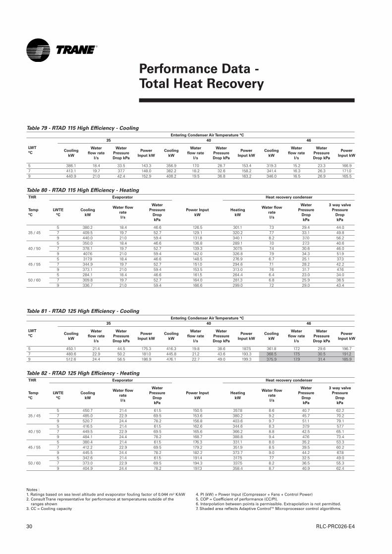
Performance Data - Total Heat Recovery
RLC-PRC026-E430
Notes :1. Ratings based on sea level altitude and evaporator fouling factor of 0.044 m² K/kW2. Consult Trane representative for performance at temperatures outside of the
ranges shown3. CC = Cooling capacity
4. PI (kW) = Power Input (Compressor + Fans + Control Power)5. COP = Coefficient of performance (CC/PI).6. Interpolation between points is permissible. Extrapolation is not permitted.7. Shaded area reflects Adaptive ControlTM Microprocessor control algorithms.
Table 79 - RTAD 115 High Efficiency - Cooling
Entering Condenser Air Temperature °C
35 40 46
5 386.1 18.4 33.5 143.3 356.9 17.0 28.7 153.4 319.3 15.2 23.3 166.97 413.1 19.7 37.7 148.0 382.2 18.2 32.6 158.2 341.4 16.3 26.3 171.09 440.9 21.0 42.4 152.9 408.2 19.5 36.8 163.2 346.0 16.5 26.9 165.5
Table 80 - RTAD 115 High Efficiency - Heating
THR Evaporator Heat recovery condenser
5 380.2 18.4 46.6 126.5 301.1 7.3 29.4 44.035 / 45 7 409.5 19.7 52.7 129.1 320.2 7.7 33.1 49.8
9 440.0 21.0 59.4 131.8 340.1 8.2 37.0 56.25 350.0 18.4 46.6 136.8 289.1 7.0 27.3 40.6
40 / 50 7 378.1 19.7 52.7 139.3 307.5 7.4 30.6 46.09 407.6 21.0 59.4 142.0 326.8 7.9 34.3 51.95 317.9 18.4 46.6 148.5 276.9 6.7 25.1 37.3
45 / 55 7 344.9 19.7 52.7 151.0 294.6 7.1 28.2 42.29 373.1 21.0 59.4 153.5 313.0 7.6 31.7 47.65 284.1 18.4 46.6 161.5 264.4 6.4 23.0 34.0
50 / 60 7 309.8 19.7 52.7 164.0 281.3 6.8 25.9 38.59 336.7 21.0 59.4 166.6 299.0 7.2 29.0 43.4
LWT
°CCooling
kW
Water
flow rate
l/s
Water
Pressure
Drop kPa
Power
Input kW
Cooling
kW
Water
flow rate
l/s
Water
Pressure
Drop kPa
Power
Input kW
Cooling
kW
Water
flow rate
l/s
Water
Pressure
Drop kPa
Power
Input kW
Temp
°C
LWTE
°C
Cooling
kW
Water flow
rate
l/s
Water
Pressure
Drop
kPa
Power Input
kW
Heating
kW
Water flow
rate
l/s
Water
Pressure
Drop
kPa
3 way valve
Pressure
Drop
kPa
Table 81 - RTAD 125 High Efficiency - Cooling
Entering Condenser Air Temperature °C
35 40 46
5 450.1 21.4 44.5 175.3 416.3 19.8 38.6 187.5 361.8 17.2 29.6 196.77 480.6 22.9 50.2 181.0 445.8 21.2 43.6 193.3 368.5 17.5 30.5 191.29 512.6 24.4 56.5 186.9 476.1 22.7 49.0 199.3 375.9 17.9 31.4 185.9
Table 82 - RTAD 125 High Efficiency - Heating
THR Evaporator Heat recovery condenser
5 450.7 21.4 61.5 150.5 357.8 8.6 40.7 62.235 / 45 7 485.0 22.9 69.5 153.6 380.2 9.2 45.7 70.2
9 520.7 24.4 78.2 156.8 403.6 9.7 51.1 79.15 416.5 21.4 61.5 162.6 344.6 8.3 37.9 57.7
40 / 50 7 449.5 22.9 69.5 165.6 366.2 8.8 42.5 65.19 484.1 24.4 78.2 168.7 388.8 9.4 47.6 73.45 380.4 21.4 61.5 176.3 331.1 8.0 35.2 53.3
45 / 55 7 412.2 22.9 69.5 179.2 351.9 8.5 39.5 60.29 445.5 24.4 78.2 182.2 373.7 9.0 44.2 67.85 342.6 21.4 61.5 191.4 317.5 7.7 32.5 49.0
50 / 60 7 373.0 22.9 69.5 194.3 337.5 8.2 36.5 55.39 404.9 24.4 78.2 197.3 358.4 8.7 40.9 62.4
LWT
°CCooling
kW
Water
flow rate
l/s
Water
Pressure
Drop kPa
Power
Input kW
Cooling
kW
Water
flow rate
l/s
Water
Pressure
Drop kPa
Power
Input kW
Cooling
kW
Water
flow rate
l/s
Water
Pressure
Drop kPa
Power
Input kW
Temp
°C
LWTE
°C
Cooling
kW
Water flow
rate
l/s
Water
Pressure
Drop
kPa
Power Input
kW
Heating
kW
Water flow
rate
l/s
Water
Pressure
Drop
kPa
3 way valve
Pressure
Drop
kPa

Performance Data - Total Heat Recovery
31RLC-PRC026-E4
Notes :1. Ratings based on sea level altitude and evaporator fouling factor of 0.044 m² K/kW2. Consult Trane representative for performance at temperatures outside of the
ranges shown3. CC = Cooling capacity
4. PI (kW) = Power Input (Compressor + Fans + Control Power)5. COP = Coefficient of performance (CC/PI).6. Interpolation between points is permissible. Extrapolation is not permitted.7. Shaded area reflects Adaptive ControlTM Microprocessor control algorithms.
Table 83 - RTAD 145 High Efficiency - Cooling
Entering Condenser Air Temperature °C
35 40 46
5 485.6 23.1 41.2 182.0 451.5 21.5 35.9 194.5 408.6 19.4 29.9 211.37 519.0 24.7 46.6 187.9 483.1 23.0 40.6 200.6 413.1 19.7 30.2 204.79 553.4 26.4 52.3 194.1 516.2 24.6 45.7 206.8 415.6 19.8 30.5 196.7
Table 84 - RTAD 145 High Efficiency - Heating
THR Evaporator Heat recovery condenser
5 485.6 23.1 22.8 161.5 384.0 9.3 38.4 28.335 / 45 7 521.4 24.7 25.6 164.9 407.5 9.8 42.9 31.9
9 558.7 26.4 28.6 168.5 432.1 10.4 48.0 35.85 449.1 23.1 22.8 174.3 369.8 8.9 35.7 26.2
40 / 50 7 483.8 24.7 25.6 177.6 392.6 9.5 40.0 29.69 520.1 26.4 28.6 181.0 416.4 10.1 44.7 33.35 410.6 23.1 22.8 188.6 355.3 8.6 33.1 24.2
45 / 55 7 443.9 24.7 25.6 191.9 377.2 9.1 37.1 27.39 478.7 26.4 28.6 195.2 400.1 9.7 41.5 30.75 370.2 23.1 22.8 204.5 340.6 8.2 30.5 22.2
50 / 60 7 402.0 24.7 25.6 207.8 361.6 8.7 34.2 25.19 435.2 26.4 28.6 211.1 383.5 9.3 38.3 28.2
LWT
°CCooling
kW
Water
flow rate
l/s
Water
Pressure
Drop kPa
Power
Input kW
Cooling
kW
Water
flow rate
l/s
Water
Pressure
Drop kPa
Power
Input kW
Cooling
kW
Water
flow rate
l/s
Water
Pressure
Drop kPa
Power
Input kW
Temp
°C
LWTE
°C
Cooling
kW
Water flow
rate
l/s
Water
Pressure
Drop
kPa
Power Input
kW
Heating
kW
Water flow
rate
l/s
Water
Pressure
Drop
kPa
3 way valve
Pressure
Drop
kPa
Table 85 - RTAD 150 High Efficiency - Cooling
Entering Condenser Air Temperature °C
35 40 46
5 521.4 24.8 47.2 201.3 484.9 23.1 41.2 214.8 438.8 20.9 34.1 232.97 556.2 26.5 52.9 208.0 517.9 24.7 46.3 221.7 445.8 21.2 35.0 226.99 592.1 28.2 59.5 215.1 552.0 26.3 52.0 228.9 450.8 21.5 35.6 219.5
Table 86 - RTAD 150 High Efficiency - Heating
THR Evaporator Heat recovery condenser
5 522.7 24.8 25.7 177.0 415.1 10.0 44.5 33.135 / 45 7 560.8 26.5 28.8 181.0 440.4 10.6 49.7 37.2
9 600.3 28.2 32.2 185.2 466.6 11.3 55.5 41.85 484.0 24.8 25.7 190.6 400.0 9.7 41.5 30.7
40 / 50 7 520.5 26.5 28.8 194.4 424.3 10.2 46.3 34.59 558.6 28.2 32.2 198.5 449.6 10.9 51.7 38.85 443.2 24.8 25.7 205.8 384.7 9.3 38.5 28.4
45 / 55 7 478.2 26.5 28.8 209.6 408.0 9.9 43.0 31.99 514.6 28.2 32.2 213.6 432.2 10.4 48.0 35.85 400.4 24.8 25.7 222.8 369.3 8.9 35.6 26.1
50 / 60 7 433.7 26.5 28.8 226.6 391.5 9.5 39.8 29.49 468.5 28.2 32.2 230.5 414.7 10.0 44.4 33.0
LWT
°CCooling
kW
Water
flow rate
l/s
Water
Pressure
Drop kPa
Power
Input kW
Cooling
kW
Water
flow rate
l/s
Water
Pressure
Drop kPa
Power
Input kW
Cooling
kW
Water
flow rate
l/s
Water
Pressure
Drop kPa
Power
Input kW
Temp
°C
LWTE
°C
Cooling
kW
Water flow
rate
l/s
Water
Pressure
Drop
kPa
Power Input
kW
Heating
kW
Water flow
rate
l/s
Water
Pressure
Drop
kPa
3 way valve
Pressure
Drop
kPa
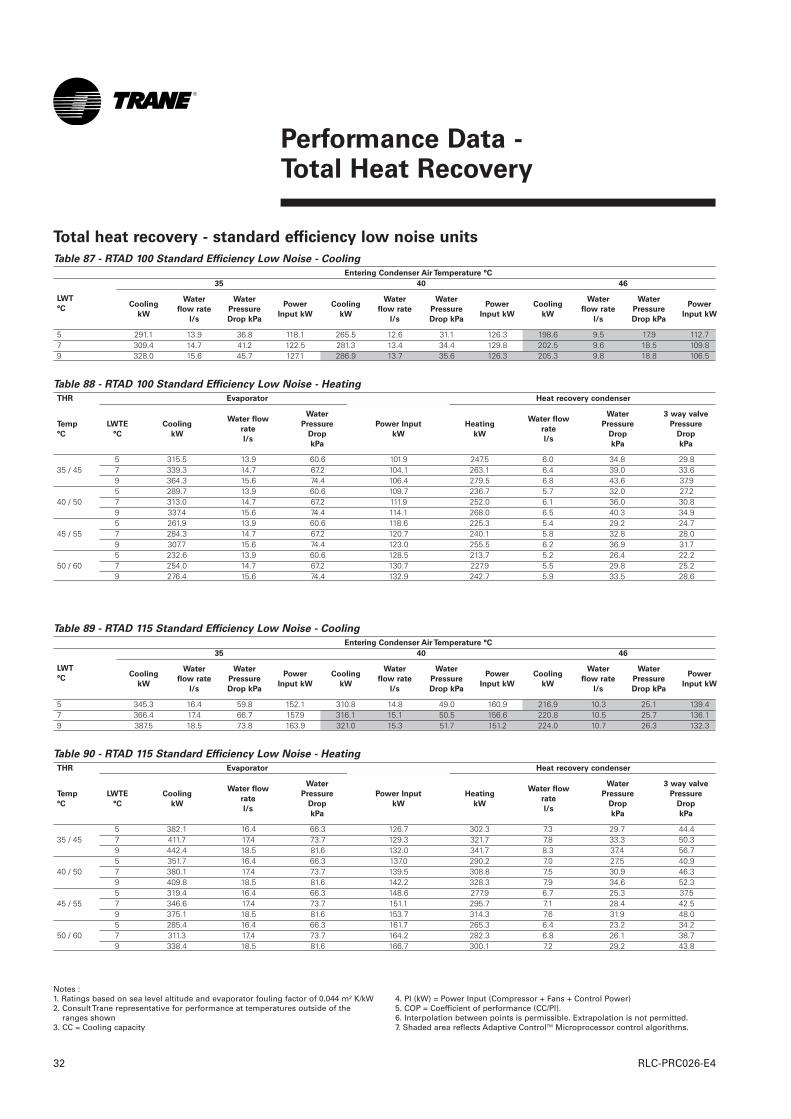
Performance Data - Total Heat Recovery
RLC-PRC026-E432
Notes :1. Ratings based on sea level altitude and evaporator fouling factor of 0.044 m² K/kW2. Consult Trane representative for performance at temperatures outside of the
ranges shown3. CC = Cooling capacity
4. PI (kW) = Power Input (Compressor + Fans + Control Power)5. COP = Coefficient of performance (CC/PI).6. Interpolation between points is permissible. Extrapolation is not permitted.7. Shaded area reflects Adaptive ControlTM Microprocessor control algorithms.
Table 87 - RTAD 100 Standard Efficiency Low Noise - Cooling
Entering Condenser Air Temperature °C
35 40 46
5 291.1 13.9 36.8 118.1 265.5 12.6 31.1 126.3 198.6 9.5 17.9 112.77 309.4 14.7 41.2 122.5 281.3 13.4 34.4 129.8 202.5 9.6 18.5 109.89 328.0 15.6 45.7 127.1 286.9 13.7 35.6 126.3 205.3 9.8 18.8 106.5
Table 88 - RTAD 100 Standard Efficiency Low Noise - Heating
THR Evaporator Heat recovery condenser
5 315.5 13.9 60.6 101.9 247.5 6.0 34.8 29.835 / 45 7 339.3 14.7 67.2 104.1 263.1 6.4 39.0 33.6
9 364.3 15.6 74.4 106.4 279.5 6.8 43.6 37.95 289.7 13.9 60.6 109.7 236.7 5.7 32.0 27.2
40 / 50 7 313.0 14.7 67.2 111.9 252.0 6.1 36.0 30.89 337.4 15.6 74.4 114.1 268.0 6.5 40.3 34.95 261.9 13.9 60.6 118.6 225.3 5.4 29.2 24.7
45 / 55 7 284.3 14.7 67.2 120.7 240.1 5.8 32.8 28.09 307.7 15.6 74.4 123.0 255.5 6.2 36.9 31.75 232.6 13.9 60.6 128.5 213.7 5.2 26.4 22.2
50 / 60 7 254.0 14.7 67.2 130.7 227.9 5.5 29.8 25.29 276.4 15.6 74.4 132.9 242.7 5.9 33.5 28.6
LWT
°CCooling
kW
Water
flow rate
l/s
Water
Pressure
Drop kPa
Power
Input kW
Cooling
kW
Water
flow rate
l/s
Water
Pressure
Drop kPa
Power
Input kW
Cooling
kW
Water
flow rate
l/s
Water
Pressure
Drop kPa
Power
Input kW
Temp
°C
LWTE
°C
Cooling
kW
Water flow
rate
l/s
Water
Pressure
Drop
kPa
Power Input
kW
Heating
kW
Water flow
rate
l/s
Water
Pressure
Drop
kPa
3 way valve
Pressure
Drop
kPa
Table 89 - RTAD 115 Standard Efficiency Low Noise - Cooling
Entering Condenser Air Temperature °C
35 40 46
5 345.3 16.4 59.8 152.1 310.8 14.8 49.0 160.9 216.9 10.3 25.1 139.47 366.4 17.4 66.7 157.9 316.1 15.1 50.5 156.6 220.8 10.5 25.7 136.19 387.5 18.5 73.8 163.9 321.0 15.3 51.7 151.2 224.0 10.7 26.3 132.3
Table 90 - RTAD 115 Standard Efficiency Low Noise - Heating
THR Evaporator Heat recovery condenser
5 382.1 16.4 66.3 126.7 302.3 7.3 29.7 44.435 / 45 7 411.7 17.4 73.7 129.3 321.7 7.8 33.3 50.3
9 442.4 18.5 81.6 132.0 341.7 8.3 37.4 56.75 351.7 16.4 66.3 137.0 290.2 7.0 27.5 40.9
40 / 50 7 380.1 17.4 73.7 139.5 308.8 7.5 30.9 46.39 409.8 18.5 81.6 142.2 328.3 7.9 34.6 52.35 319.4 16.4 66.3 148.6 277.9 6.7 25.3 37.5
45 / 55 7 346.6 17.4 73.7 151.1 295.7 7.1 28.4 42.59 375.1 18.5 81.6 153.7 314.3 7.6 31.9 48.05 285.4 16.4 66.3 161.7 265.3 6.4 23.2 34.2
50 / 60 7 311.3 17.4 73.7 164.2 282.3 6.8 26.1 38.79 338.4 18.5 81.6 166.7 300.1 7.2 29.2 43.8
LWT
°CCooling
kW
Water
flow rate
l/s
Water
Pressure
Drop kPa
Power
Input kW
Cooling
kW
Water
flow rate
l/s
Water
Pressure
Drop kPa
Power
Input kW
Cooling
kW
Water
flow rate
l/s
Water
Pressure
Drop kPa
Power
Input kW
Temp
°C
LWTE
°C
Cooling
kW
Water flow
rate
l/s
Water
Pressure
Drop
kPa
Power Input
kW
Heating
kW
Water flow
rate
l/s
Water
Pressure
Drop
kPa
3 way valve
Pressure
Drop
kPa
Total heat recovery - standard efficiency low noise units
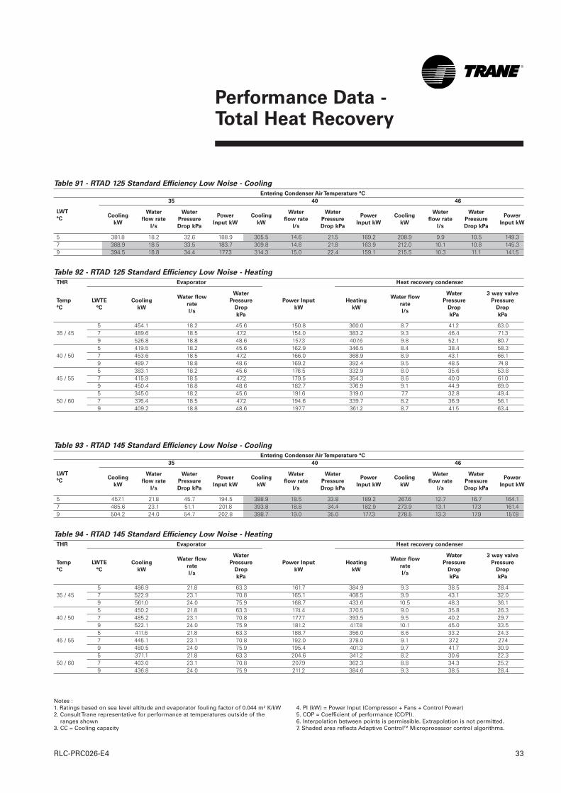
Performance Data - Total Heat Recovery
33RLC-PRC026-E4
Notes :1. Ratings based on sea level altitude and evaporator fouling factor of 0.044 m² K/kW2. Consult Trane representative for performance at temperatures outside of the
ranges shown3. CC = Cooling capacity
4. PI (kW) = Power Input (Compressor + Fans + Control Power)5. COP = Coefficient of performance (CC/PI).6. Interpolation between points is permissible. Extrapolation is not permitted.7. Shaded area reflects Adaptive ControlTM Microprocessor control algorithms.
Table 91 - RTAD 125 Standard Efficiency Low Noise - Cooling
Entering Condenser Air Temperature °C
35 40 46
5 381.8 18.2 32.6 188.9 305.5 14.6 21.5 169.2 208.9 9.9 10.5 149.37 388.9 18.5 33.5 183.7 309.8 14.8 21.8 163.9 212.0 10.1 10.8 145.39 394.5 18.8 34.4 177.3 314.3 15.0 22.4 159.1 215.5 10.3 11.1 141.5
Table 92 - RTAD 125 Standard Efficiency Low Noise - Heating
THR Evaporator Heat recovery condenser
5 454.1 18.2 45.6 150.8 360.0 8.7 41.2 63.035 / 45 7 489.6 18.5 47.2 154.0 383.2 9.3 46.4 71.3
9 526.8 18.8 48.6 157.3 407.6 9.8 52.1 80.75 419.5 18.2 45.6 162.9 346.5 8.4 38.4 58.3
40 / 50 7 453.6 18.5 47.2 166.0 368.9 8.9 43.1 66.19 489.7 18.8 48.6 169.2 392.4 9.5 48.5 74.85 383.1 18.2 45.6 176.5 332.9 8.0 35.6 53.8
45 / 55 7 415.9 18.5 47.2 179.5 354.3 8.6 40.0 61.09 450.4 18.8 48.6 182.7 376.9 9.1 44.9 69.05 345.0 18.2 45.6 191.6 319.0 7.7 32.8 49.4
50 / 60 7 376.4 18.5 47.2 194.6 339.7 8.2 36.9 56.19 409.2 18.8 48.6 197.7 361.2 8.7 41.5 63.4
LWT
°CCooling
kW
Water
flow rate
l/s
Water
Pressure
Drop kPa
Power
Input kW
Cooling
kW
Water
flow rate
l/s
Water
Pressure
Drop kPa
Power
Input kW
Cooling
kW
Water
flow rate
l/s
Water
Pressure
Drop kPa
Power
Input kW
Temp
°C
LWTE
°C
Cooling
kW
Water flow
rate
l/s
Water
Pressure
Drop
kPa
Power Input
kW
Heating
kW
Water flow
rate
l/s
Water
Pressure
Drop
kPa
3 way valve
Pressure
Drop
kPa
Table 93 - RTAD 145 Standard Efficiency Low Noise - Cooling
Entering Condenser Air Temperature °C
35 40 46
5 457.1 21.8 45.7 194.5 388.9 18.5 33.8 189.2 267.6 12.7 16.7 164.17 485.6 23.1 51.1 201.8 393.8 18.8 34.4 182.9 273.9 13.1 17.3 161.49 504.2 24.0 54.7 202.8 398.7 19.0 35.0 177.3 278.5 13.3 17.9 157.8
Table 94 - RTAD 145 Standard Efficiency Low Noise - Heating
THR Evaporator Heat recovery condenser
5 486.9 21.8 63.3 161.7 384.9 9.3 38.5 28.435 / 45 7 522.9 23.1 70.8 165.1 408.5 9.9 43.1 32.0
9 561.0 24.0 75.9 168.7 433.6 10.5 48.3 36.15 450.2 21.8 63.3 174.4 370.5 9.0 35.8 26.3
40 / 50 7 485.2 23.1 70.8 177.7 393.5 9.5 40.2 29.79 522.1 24.0 75.9 181.2 417.8 10.1 45.0 33.55 411.6 21.8 63.3 188.7 356.0 8.6 33.2 24.3
45 / 55 7 445.1 23.1 70.8 192.0 378.0 9.1 37.2 27.49 480.5 24.0 75.9 195.4 401.3 9.7 41.7 30.95 371.1 21.8 63.3 204.6 341.2 8.2 30.6 22.3
50 / 60 7 403.0 23.1 70.8 207.9 362.3 8.8 34.3 25.29 436.8 24.0 75.9 211.2 384.6 9.3 38.5 28.4
LWT
°CCooling
kW
Water
flow rate
l/s
Water
Pressure
Drop kPa
Power
Input kW
Cooling
kW
Water
flow rate
l/s
Water
Pressure
Drop kPa
Power
Input kW
Cooling
kW
Water
flow rate
l/s
Water
Pressure
Drop kPa
Power
Input kW
Temp
°C
LWTE
°C
Cooling
kW
Water flow
rate
l/s
Water
Pressure
Drop
kPa
Power Input
kW
Heating
kW
Water flow
rate
l/s
Water
Pressure
Drop
kPa
3 way valve
Pressure
Drop
kPa
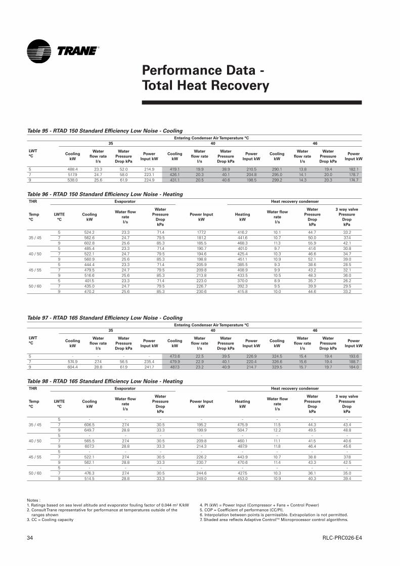
Performance Data - Total Heat Recovery
RLC-PRC026-E434
Notes :1. Ratings based on sea level altitude and evaporator fouling factor of 0.044 m² K/kW2. Consult Trane representative for performance at temperatures outside of the
ranges shown3. CC = Cooling capacity
4. PI (kW) = Power Input (Compressor + Fans + Control Power)5. COP = Coefficient of performance (CC/PI).6. Interpolation between points is permissible. Extrapolation is not permitted.7. Shaded area reflects Adaptive ControlTM Microprocessor control algorithms.
Table 95 - RTAD 150 Standard Efficiency Low Noise - Cooling
Entering Condenser Air Temperature °C
35 40 46
5 488.4 23.3 52.0 214.9 419.1 19.9 38.9 210.5 290.1 13.8 19.4 182.17 517.9 24.7 58.0 223.1 426.1 20.3 40.1 204.8 295.0 14.1 20.0 178.79 538.0 25.6 61.9 224.9 431.1 20.5 40.6 198.5 299.2 14.3 20.3 174.7
Table 96 - RTAD 150 Standard Efficiency Low Noise - Heating
THR Evaporator Heat recovery condenser
5 524.2 23.3 71.4 177.2 416.2 10.1 44.7 33.235 / 45 7 562.6 24.7 79.5 181.2 441.6 10.7 50.0 37.4
9 602.8 25.6 85.3 185.5 468.3 11.3 55.9 42.15 485.4 23.3 71.4 190.7 401.0 9.7 41.6 30.8
40 / 50 7 522.1 24.7 79.5 194.6 425.4 10.3 46.6 34.79 560.9 25.6 85.3 198.8 451.1 10.9 52.1 39.05 444.4 23.3 71.4 205.9 385.5 9.3 38.6 28.5
45 / 55 7 479.5 24.7 79.5 209.8 408.9 9.9 43.2 32.19 516.6 25.6 85.3 213.8 433.5 10.5 48.3 36.05 401.5 23.3 71.4 223.0 370.0 8.9 35.7 26.2
50 / 60 7 435.0 24.7 79.5 226.7 392.3 9.5 39.9 29.59 470.2 25.6 85.3 230.6 415.8 10.0 44.6 33.2
LWT
°CCooling
kW
Water
flow rate
l/s
Water
Pressure
Drop kPa
Power
Input kW
Cooling
kW
Water
flow rate
l/s
Water
Pressure
Drop kPa
Power
Input kW
Cooling
kW
Water
flow rate
l/s
Water
Pressure
Drop kPa
Power
Input kW
Temp
°C
LWTE
°C
Cooling
kW
Water flow
rate
l/s
Water
Pressure
Drop
kPa
Power Input
kW
Heating
kW
Water flow
rate
l/s
Water
Pressure
Drop
kPa
3 way valve
Pressure
Drop
kPa
Table 97 - RTAD 165 Standard Efficiency Low Noise - Cooling
Entering Condenser Air Temperature °C
35 40 46
5 - - - - 473.6 22.5 39.5 226.9 324.5 15.4 19.4 193.67 574.9 27.4 56.5 235.4 479.9 22.9 40.1 220.4 326.6 15.6 19.4 188.79 604.4 28.8 61.9 241.7 487.3 23.2 40.9 214.7 329.5 15.7 19.7 184.0
Table 98 - RTAD 165 Standard Efficiency Low Noise - Heating
THR Evaporator Heat recovery condenser
5 - - - - - - - -35 / 45 7 606.5 27.4 30.5 195.2 475.9 11.5 44.3 43.4
9 649.7 28.8 33.3 199.9 504.7 12.2 49.5 48.85 - - - - - - - -
40 / 50 7 565.5 27.4 30.5 209.8 460.1 11.1 41.5 40.69 607.3 28.8 33.3 214.3 487.9 11.8 46.4 45.65 - - - - - - - -
45 / 55 7 522.1 27.4 30.5 226.2 443.9 10.7 38.8 37.89 562.1 28.8 33.3 230.7 470.6 11.4 43.3 42.55 - - - - - - - -
50 / 60 7 476.3 27.4 30.5 244.6 427.5 10.3 36.1 35.09 514.5 28.8 33.3 249.0 453.0 10.9 40.3 39.4
LWT
°CCooling
kW
Water
flow rate
l/s
Water
Pressure
Drop kPa
Power
Input kW
Cooling
kW
Water
flow rate
l/s
Water
Pressure
Drop kPa
Power
Input kW
Cooling
kW
Water
flow rate
l/s
Water
Pressure
Drop kPa
Power
Input kW
Temp
°C
LWTE
°C
Cooling
kW
Water flow
rate
l/s
Water
Pressure
Drop
kPa
Power Input
kW
Heating
kW
Water flow
rate
l/s
Water
Pressure
Drop
kPa
3 way valve
Pressure
Drop
kPa
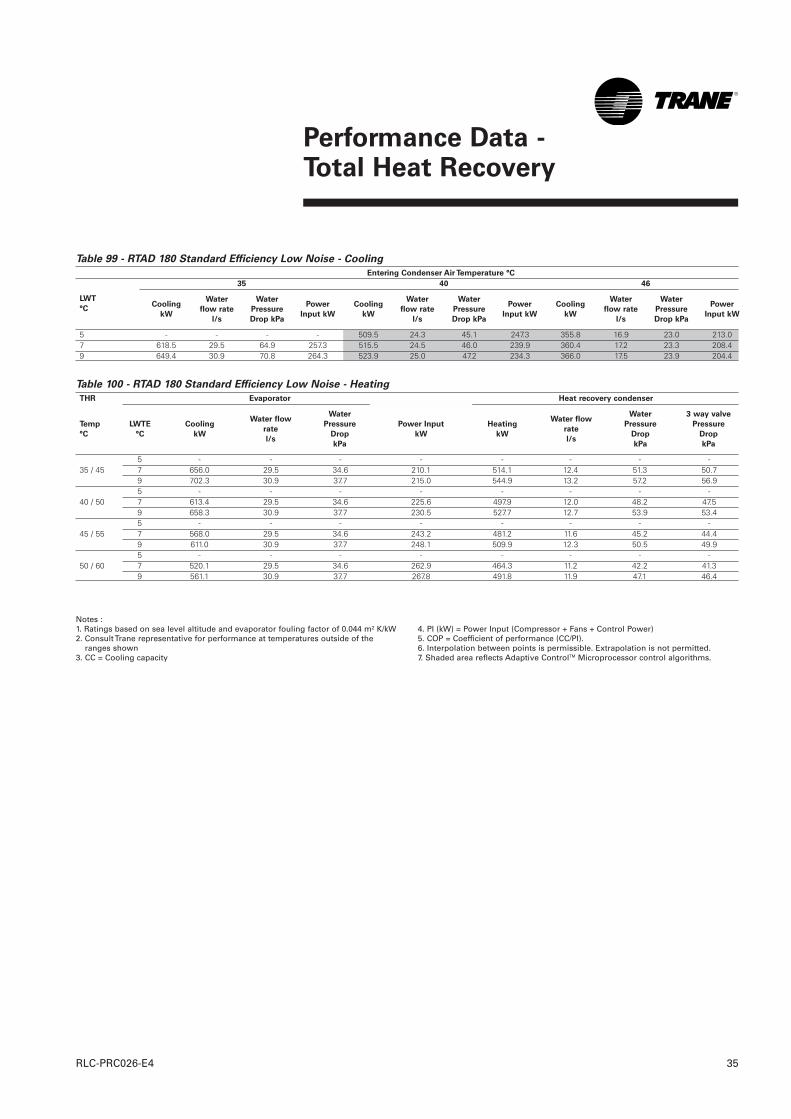
Performance Data - Total Heat Recovery
35RLC-PRC026-E4
Notes :1. Ratings based on sea level altitude and evaporator fouling factor of 0.044 m² K/kW2. Consult Trane representative for performance at temperatures outside of the
ranges shown3. CC = Cooling capacity
4. PI (kW) = Power Input (Compressor + Fans + Control Power)5. COP = Coefficient of performance (CC/PI).6. Interpolation between points is permissible. Extrapolation is not permitted.7. Shaded area reflects Adaptive ControlTM Microprocessor control algorithms.
Table 99 - RTAD 180 Standard Efficiency Low Noise - Cooling
Entering Condenser Air Temperature °C
35 40 46
5 - - - - 509.5 24.3 45.1 247.3 355.8 16.9 23.0 213.07 618.5 29.5 64.9 257.3 515.5 24.5 46.0 239.9 360.4 17.2 23.3 208.49 649.4 30.9 70.8 264.3 523.9 25.0 47.2 234.3 366.0 17.5 23.9 204.4
Table 100 - RTAD 180 Standard Efficiency Low Noise - Heating
THR Evaporator Heat recovery condenser
5 - - - - - - - -35 / 45 7 656.0 29.5 34.6 210.1 514.1 12.4 51.3 50.7
9 702.3 30.9 37.7 215.0 544.9 13.2 57.2 56.95 - - - - - - - -
40 / 50 7 613.4 29.5 34.6 225.6 497.9 12.0 48.2 47.59 658.3 30.9 37.7 230.5 527.7 12.7 53.9 53.45 - - - - - - - -
45 / 55 7 568.0 29.5 34.6 243.2 481.2 11.6 45.2 44.49 611.0 30.9 37.7 248.1 509.9 12.3 50.5 49.95 - - - - - - - -
50 / 60 7 520.1 29.5 34.6 262.9 464.3 11.2 42.2 41.39 561.1 30.9 37.7 267.8 491.8 11.9 47.1 46.4
LWT
°CCooling
kW
Water
flow rate
l/s
Water
Pressure
Drop kPa
Power
Input kW
Cooling
kW
Water
flow rate
l/s
Water
Pressure
Drop kPa
Power
Input kW
Cooling
kW
Water
flow rate
l/s
Water
Pressure
Drop kPa
Power
Input kW
Temp
°C
LWTE
°C
Cooling
kW
Water flow
rate
l/s
Water
Pressure
Drop
kPa
Power Input
kW
Heating
kW
Water flow
rate
l/s
Water
Pressure
Drop
kPa
3 way valve
Pressure
Drop
kPa
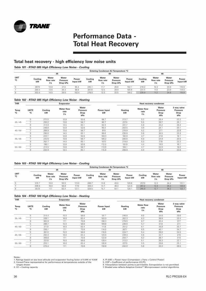
Table 101 - RTAD 085 High Efficiency Low Noise - Cooling
Entering Condenser Air Temperature °C
35 40 46
5 267.9 12.8 31.4 95.4 245.1 11.7 26.6 102.1 216.2 10.3 20.9 110.97 285.5 13.6 35.3 98.8 261.6 12.5 29.9 105.6 231.4 11.0 23.9 114.59 303.4 14.5 39.5 102.4 278.5 13.3 33.5 109.2 235.9 11.2 24.5 110.9
Table 102 - RTAD 085 High Efficiency Low Noise - Heating
THR Evaporator Heat recovery condenser
5 272.5 12.8 52.6 88.7 213.7 5.2 26.4 22.235 / 45 7 293.2 13.6 58.7 90.7 227.4 5.5 29.7 25.1
9 314.9 14.5 65.1 92.9 241.7 5.8 33.2 28.45 248.6 12.8 52.6 95.5 203.5 4.9 24.1 20.1
40 / 50 7 268.9 13.6 58.7 97.5 216.9 5.2 27.1 22.89 290.0 14.5 65.1 99.6 230.8 5.6 30.5 25.95 223.1 12.8 52.6 103.3 192.9 4.7 21.8 18.1
45 / 55 7 242.5 13.6 58.7 105.2 205.6 5.0 24.6 20.59 262.7 14.5 65.1 107.2 219.0 5.3 27.6 23.35 196.1 12.8 52.6 112.0 181.9 4.4 19.5 16.1
50 / 60 7 214.5 13.6 58.7 113.9 194.1 4.7 22.0 18.39 233.9 14.5 65.1 115.9 206.9 5.0 24.8 20.8
LWT
°CCooling
kW
Water
flow rate
l/s
Water
Pressure
Drop kPa
Power
Input kW
Cooling
kW
Water
flow rate
l/s
Water
Pressure
Drop kPa
Power
Input kW
Cooling
kW
Water
flow rate
l/s
Water
Pressure
Drop kPa
Power
Input kW
Temp
°C
LWTE
°C
Cooling
kW
Water flow
rate
l/s
Water
Pressure
Drop
kPa
Power Input
kW
Heating
kW
Water flow
rate
l/s
Water
Pressure
Drop
kPa
3 way valve
Pressure
Drop
kPa
Table 103 - RTAD 100 High Efficiency Low Noise - Cooling
Entering Condenser Air Temperature °C
35 40 46
5 315.7 15.0 50.5 113.0 289.7 13.8 43.0 120.8 257.0 12.2 34.4 131.17 336.5 16.0 56.8 117.0 309.4 14.7 48.4 124.9 261.2 12.4 35.3 126.89 357.9 17.1 63.4 121.1 329.5 15.7 54.1 129.1 265.8 12.7 36.2 122.7
Table 104 - RTAD 100 High Efficiency Low Noise - Heating
THR Evaporator Heat recovery condenser
5 314.4 15.0 56.6 101.7 246.8 6.0 34.6 29.635 / 45 7 338.1 16.0 63.4 103.9 262.3 6.3 38.8 33.4
9 362.9 17.1 70.8 106.3 278.5 6.7 43.4 37.75 288.7 15.0 56.6 109.6 236.0 5.7 31.8 27.1
40 / 50 7 311.9 16.0 63.4 111.8 251.2 6.1 35.8 30.79 336.1 17.1 70.8 114.0 267.1 6.5 40.1 34.75 261.0 15.0 56.6 118.5 224.7 5.4 29.0 24.5
45 / 55 7 283.3 16.0 63.4 120.6 239.4 5.8 32.7 27.89 306.6 17.1 70.8 122.8 254.7 6.2 36.7 31.55 231.8 15.0 56.6 128.4 213.2 5.1 26.3 22.1
50 / 60 7 253.1 16.0 63.4 130.6 227.3 5.5 29.6 25.19 275.4 17.1 70.8 132.8 242.0 5.8 33.3 28.5
LWT
°CCooling
kW
Water
flow rate
l/s
Water
Pressure
Drop kPa
Power
Input kW
Cooling
kW
Water
flow rate
l/s
Water
Pressure
Drop kPa
Power
Input kW
Cooling
kW
Water
flow rate
l/s
Water
Pressure
Drop kPa
Power
Input kW
Temp
°C
LWTE
°C
Cooling
kW
Water flow
rate
l/s
Water
Pressure
Drop
kPa
Power Input
kW
Heating
kW
Water flow
rate
l/s
Water
Pressure
Drop
kPa
3 way valve
Pressure
Drop
kPa
Total heat recovery - high efficiency low noise units
Performance Data - Total Heat Recovery
RLC-PRC026-E436
Notes :1. Ratings based on sea level altitude and evaporator fouling factor of 0.044 m² K/kW2. Consult Trane representative for performance at temperatures outside of the
ranges shown3. CC = Cooling capacity
4. PI (kW) = Power Input (Compressor + Fans + Control Power)5. COP = Coefficient of performance (CC/PI).6. Interpolation between points is permissible. Extrapolation is not permitted.7. Shaded area reflects Adaptive ControlTM Microprocessor control algorithms.
Performance Data - Total Heat Recovery
37RLC-PRC026-E4
Table 105 - RTAD 115 High Efficiency Low Noise - Cooling
Entering Condenser Air Temperature °C
35 40 46
5 374.5 17.8 31.4 145.3 343.9 16.4 26.9 156.1 275.3 13.1 17.6 152.77 399.4 19.0 35.3 150.6 367.4 17.5 30.2 161.5 278.1 13.3 17.9 148.29 425.4 20.3 39.8 156.0 392.0 18.7 34.1 167.1 283.0 13.5 18.5 144.9
Table 106 - RTAD 115 High Efficiency Low Noise - Heating
THR Evaporator Heat recovery condenser
5 380.7 17.8 44.0 126.6 301.4 7.3 29.5 44.135 / 45 7 410.1 19.0 49.6 129.2 320.6 7.7 33.1 49.9
9 440.6 20.3 55.7 131.9 340.6 8.2 37.1 56.35 350.4 17.8 44.0 136.9 289.4 7.0 27.3 40.7
40 / 50 7 378.7 19.0 49.6 139.4 307.9 7.4 30.7 46.19 408.2 20.3 55.7 142.0 327.2 7.9 34.4 52.05 318.3 17.8 44.0 148.5 277.2 6.7 25.2 37.3
45 / 55 7 345.4 19.0 49.6 151.0 294.9 7.1 28.3 42.29 373.6 20.3 55.7 153.6 313.4 7.6 31.7 47.75 284.5 17.8 44.0 161.6 264.7 6.4 23.1 34.0
50 / 60 7 310.2 19.0 49.6 164.0 281.6 6.8 25.9 38.59 337.1 20.3 55.7 166.6 299.3 7.2 29.1 43.5
LWT
°CCooling
kW
Water
flow rate
l/s
Water
Pressure
Drop kPa
Power
Input kW
Cooling
kW
Water
flow rate
l/s
Water
Pressure
Drop kPa
Power
Input kW
Cooling
kW
Water
flow rate
l/s
Water
Pressure
Drop kPa
Power
Input kW
Temp
°C
LWTE
°C
Cooling
kW
Water flow
rate
l/s
Water
Pressure
Drop
kPa
Power Input
kW
Heating
kW
Water flow
rate
l/s
Water
Pressure
Drop
kPa
3 way valve
Pressure
Drop
kPa
Table 107 - RTAD 125 High Efficiency Low Noise - Cooling
Entering Condenser Air Temperature °C
35 40 46
5 434.9 20.7 41.8 178.1 400.5 19.1 35.9 191.2 295.0 14.0 20.0 170.27 463.8 22.1 46.9 184.5 423.3 20.2 39.5 195.2 300.3 14.3 20.6 165.69 493.3 23.5 52.6 191.1 428.6 20.4 40.3 188.3 304.5 14.5 21.2 161.1
Table 108 - RTAD 125 High Efficiency Low Noise - Heating
THR Evaporator Heat recovery condenser
5 451.4 20.7 57.8 150.5 358.2 8.7 40.8 62.335 / 45 7 485.7 22.1 65.1 153.6 380.7 9.2 45.8 70.4
9 521.6 23.5 72.9 156.9 404.1 9.8 51.2 79.45 417.1 20.7 57.8 162.7 345.0 8.3 38.0 57.8
40 / 50 7 450.2 22.1 65.1 165.7 366.6 8.9 42.6 65.39 484.9 23.5 72.9 168.8 389.3 9.4 47.8 73.65 381.0 20.7 57.8 176.3 331.5 8.0 35.3 53.4
45 / 55 7 412.8 22.1 65.1 179.2 352.3 8.5 39.6 60.39 446.2 23.5 72.9 182.3 374.2 9.0 44.3 68.05 343.1 20.7 57.8 191.4 317.8 7.7 32.6 49.1
50 / 60 7 373.6 22.1 65.1 194.3 337.8 8.2 36.6 55.49 405.5 23.5 72.9 197.3 358.8 8.7 40.9 62.5
LWT
°CCooling
kW
Water
flow rate
l/s
Water
Pressure
Drop kPa
Power
Input kW
Cooling
kW
Water
flow rate
l/s
Water
Pressure
Drop kPa
Power
Input kW
Cooling
kW
Water
flow rate
l/s
Water
Pressure
Drop kPa
Power
Input kW
Temp
°C
LWTE
°C
Cooling
kW
Water flow
rate
l/s
Water
Pressure
Drop
kPa
Power Input
kW
Heating
kW
Water flow
rate
l/s
Water
Pressure
Drop
kPa
3 way valve
Pressure
Drop
kPa

Notes :1. Ratings based on sea level altitude and evaporator fouling factor of 0.044 m² K/kW2. Consult Trane representative for performance at temperatures outside of the
ranges shown3. CC = Cooling capacity
4. PI (kW) = Power Input (Compressor + Fans + Control Power)5. COP = Coefficient of performance (CC/PI).6. Interpolation between points is permissible. Extrapolation is not permitted.7. Shaded area reflects Adaptive ControlTM Microprocessor control algorithms.
Performance Data - Total Heat Recovery
RLC-PRC026-E438
Table 109 - RTAD 145 High Efficiency Low Noise - Cooling
Entering Condenser Air Temperature °C
35 40 46
5 472.6 22.5 39.2 183.5 437.4 20.8 33.8 196.9 329.1 15.7 20.0 179.47 504.2 24.0 43.9 190.1 467.3 22.3 38.3 203.6 336.1 16.0 20.6 175.59 536.5 25.6 49.3 196.9 481.7 23.0 40.1 201.8 340.0 16.2 20.9 170.2
Table 110 - RTAD 145 High Efficiency Low Noise - Heating
THR Evaporator Heat recovery condenser
5 486.1 22.5 21.7 161.6 384.4 9.3 38.4 28.335 / 45 7 522.0 24.0 24.3 165.0 408.0 9.9 43.0 31.9
9 559.5 25.6 27.1 168.6 432.6 10.4 48.1 35.95 449.6 22.5 21.7 174.3 370.1 8.9 35.8 26.3
40 / 50 7 484.4 24.0 24.3 177.7 393.0 9.5 40.1 29.69 520.7 25.6 27.1 181.1 416.9 10.1 44.8 33.35 411.1 22.5 21.7 188.7 355.6 8.6 33.1 24.2
45 / 55 7 444.4 24.0 24.3 191.9 377.5 9.1 37.1 27.39 479.3 25.6 27.1 195.3 400.5 9.7 41.5 30.85 370.6 22.5 21.7 204.6 340.8 8.2 30.6 22.3
50 / 60 7 402.4 24.0 24.3 207.8 361.9 8.7 34.3 25.19 435.8 25.6 27.1 211.1 383.9 9.3 38.3 28.3
LWT
°CCooling
kW
Water
flow rate
l/s
Water
Pressure
Drop kPa
Power
Input kW
Cooling
kW
Water
flow rate
l/s
Water
Pressure
Drop kPa
Power
Input kW
Cooling
kW
Water
flow rate
l/s
Water
Pressure
Drop kPa
Power
Input kW
Temp
°C
LWTE
°C
Cooling
kW
Water flow
rate
l/s
Water
Pressure
Drop
kPa
Power Input
kW
Heating
kW
Water flow
rate
l/s
Water
Pressure
Drop
kPa
3 way valve
Pressure
Drop
kPa
Table 111 - RTAD 150 High Efficiency Low Noise - Cooling
Entering Condenser Air Temperature °C
35 40 46
5 506.7 24.1 44.8 203.1 469.0 22.3 38.6 217.7 358.6 17.1 23.3 200.37 539.4 25.7 49.9 210.6 499.6 23.8 43.3 225.4 363.9 17.3 23.9 195.09 572.8 27.3 55.9 218.4 515.8 24.6 45.7 224.3 368.8 17.6 24.2 189.9
Table 112 - RTAD 150 High Efficiency Low Noise - Heating
THR Evaporator Heat recovery condenser
5 523.4 24.1 24.5 177.1 415.6 10.0 44.6 33.135 / 45 7 561.5 25.7 27.3 181.1 440.9 10.6 49.9 37.3
9 601.1 27.3 30.4 185.3 467.2 11.3 55.6 41.95 484.6 24.1 24.5 190.6 400.4 9.7 41.5 30.8
40 / 50 7 521.2 25.7 27.3 194.5 424.8 10.3 46.4 34.69 559.4 27.3 30.4 198.6 450.1 10.9 51.8 38.95 443.8 24.1 24.5 205.9 385.1 9.3 38.6 28.4
45 / 55 7 478.8 25.7 27.3 209.7 408.4 9.9 43.1 32.09 515.3 27.3 30.4 213.6 432.7 10.5 48.1 35.95 400.9 24.1 24.5 222.9 369.6 8.9 35.7 26.2
50 / 60 7 434.3 25.7 27.3 226.7 391.9 9.5 39.9 29.49 469.1 27.3 30.4 230.5 415.1 10.0 44.5 33.0
LWT
°CCooling
kW
Water
flow rate
l/s
Water
Pressure
Drop kPa
Power
Input kW
Cooling
kW
Water
flow rate
l/s
Water
Pressure
Drop kPa
Power
Input kW
Cooling
kW
Water
flow rate
l/s
Water
Pressure
Drop kPa
Power
Input kW
Temp
°C
LWTE
°C
Cooling
kW
Water flow
rate
l/s
Water
Pressure
Drop
kPa
Power Input
kW
Heating
kW
Water flow
rate
l/s
Water
Pressure
Drop
kPa
3 way valve
Pressure
Drop
kPa
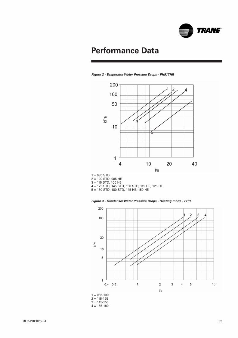
Performance Data
39RLC-PRC026-E4
Figure 2 - Evaporator Water Pressure Drops - PHR/THR
1 = 085 STD2 = 100 STD, 085 HE3 = 115 STD, 100 HE4 = 125 STD, 145 STD, 150 STD, 115 HE, 125 HE5 = 160 STD, 180 STD, 145 HE, 150 HE
Figure 3 - Condenser Water Pressure Drops - Heating mode - PHR
1 = 085-1002 = 115-1253 = 145-1504 = 165-180
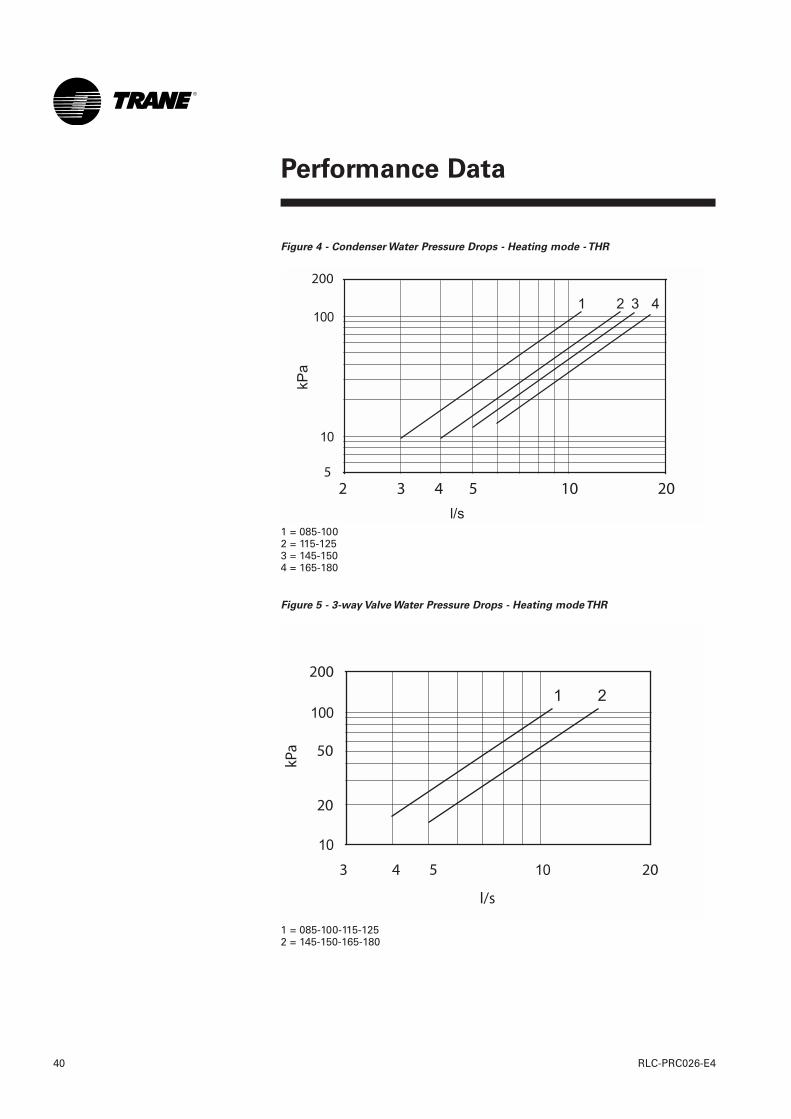
Performance Data
RLC-PRC026-E440
Figure 4 - Condenser Water Pressure Drops - Heating mode - THR
1 = 085-1002 = 115-1253 = 145-1504 = 165-180
Figure 5 - 3-way Valve Water Pressure Drops - Heating mode THR
1 = 085-100-115-1252 = 145-150-165-180
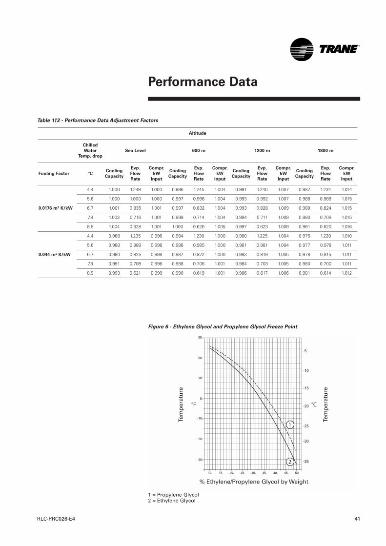
Performance Data
41RLC-PRC026-E4
Table 113 - Performance Data Adjustment Factors
Altitude
Chilled
Water
Temp. drop
Sea Level 600 m 1200 m 1800 m
Fouling Factor °C Cooling
Capacity
Evp.
Flow
Rate
Compr.
kW
Input
Cooling
Capacity
Evp.
Flow
Rate
Compr.
kW
Input
Cooling
Capacity
Evp.
Flow
Rate
Compr.
kW
Input
Cooling
Capacity
Evp.
Flow
Rate
Compr.
kW
Input
0.0176 m² K/kW
4.4 1.000 1.249 1.000 0.996 1.245 1.004 0.991 1.240 1.007 0.987 1.234 1.014
5.6 1.000 1.000 1.000 0.997 0.996 1.004 0.993 0.992 1.007 0.988 0.988 1.015
6.7 1.001 0.835 1.001 0.997 0.832 1.004 0.993 0.828 1.009 0.988 0.824 1.015
7.8 1.003 0.716 1.001 0.999 0.714 1.004 0.994 0.711 1.009 0.990 0.708 1.015
8.9 1.004 0.628 1.001 1.000 0.626 1.005 0.997 0.623 1.009 0.991 0.620 1.016
0.044 m² K/kW
4.4 0.988 1.235 0.996 0.984 1.230 1.000 0.980 1.225 1.004 0.975 1.220 1.010
5.6 0.988 0.989 0.998 0.986 0.985 1.000 0.981 0.981 1.004 0.977 0.976 1.011
6.7 0.990 0.825 0.998 0.987 0.822 1.000 0.983 0.819 1.005 0.978 0.815 1.011
7.8 0.991 0.708 0.998 0.988 0.706 1.001 0.984 0.703 1.005 0.980 0.700 1.011
8.9 0.993 0.621 0.999 0.990 0.619 1.001 0.986 0.617 1.006 0.981 0.614 1.012
Figure 6 - Ethylene Glycol and Propylene Glycol Freeze Point
1 = Propylene Glycol2 = Ethylene Glycol
1
2
Tem
per
atu
re
Tem
per
atu
re
% Ethylene/Propylene Glycol by Weight
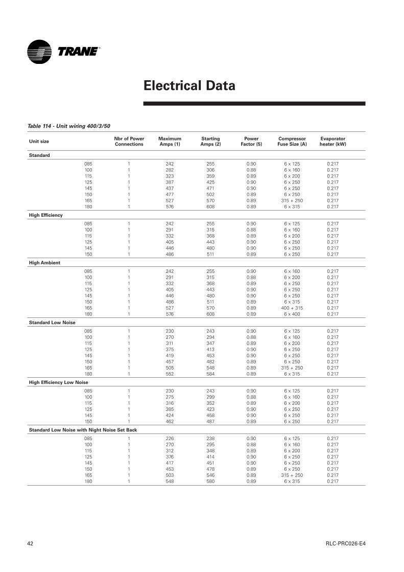
RLC-PRC026-E442
Electrical Data
Table 114 - Unit wiring 400/3/50
Unit size
Standard
085 1 242 255 0.90 6 x 125 0.217100 1 282 306 0.88 6 x 160 0.217115 1 323 359 0.89 6 x 200 0.217125 1 387 425 0.90 6 x 250 0.217145 1 437 471 0.90 6 x 250 0.217150 1 477 502 0.89 6 x 250 0.217165 1 527 570 0.89 315 + 250 0.217180 1 576 608 0.89 6 x 315 0.217
High Efficiency
085 1 242 255 0.90 6 x 125 0.217100 1 291 315 0.88 6 x 160 0.217115 1 332 368 0.89 6 x 200 0.217125 1 405 443 0.90 6 x 250 0.217145 1 446 480 0.90 6 x 250 0.217150 1 486 511 0.89 6 x 250 0.217
High Ambient
085 1 242 255 0.90 6 x 160 0.217100 1 291 315 0.88 6 x 200 0.217115 1 332 368 0.89 6 x 250 0.217125 1 405 443 0.90 6 x 250 0.217145 1 446 480 0.90 6 x 250 0.217150 1 486 511 0.89 6 x 315 0.217165 1 527 570 0.89 400 + 315 0.217180 1 576 608 0.89 6 x 400 0.217
Standard Low Noise
085 1 230 243 0.90 6 x 125 0.217100 1 270 294 0.88 6 x 160 0.217115 1 311 347 0.89 6 x 200 0.217125 1 375 413 0.90 6 x 250 0.217145 1 419 453 0.90 6 x 250 0.217150 1 457 482 0.89 6 x 250 0.217165 1 505 548 0.89 315 + 250 0.217180 1 552 584 0.89 6 x 315 0.217
High Efficiency Low Noise
085 1 230 243 0.90 6 x 125 0.217100 1 275 299 0.88 6 x 160 0.217115 1 316 352 0.89 6 x 200 0.217125 1 385 423 0.90 6 x 250 0.217145 1 424 458 0.90 6 x 250 0.217150 1 462 487 0.89 6 x 250 0.217
Standard Low Noise with Night Noise Set Back
085 1 226 238 0.90 6 x 125 0.217100 1 270 295 0.88 6 x 160 0.217115 1 312 348 0.89 6 x 200 0.217125 1 376 414 0.90 6 x 250 0.217145 1 417 451 0.90 6 x 250 0.217150 1 453 478 0.89 6 x 250 0.217165 1 503 546 0.89 315 + 250 0.217180 1 548 580 0.89 6 x 315 0.217
Nbr of PowerConnections
MaximumAmps (1)
Starting Amps (2)
Power Factor (5)
CompressorFuse Size (A)
Evaporatorheater (kW)
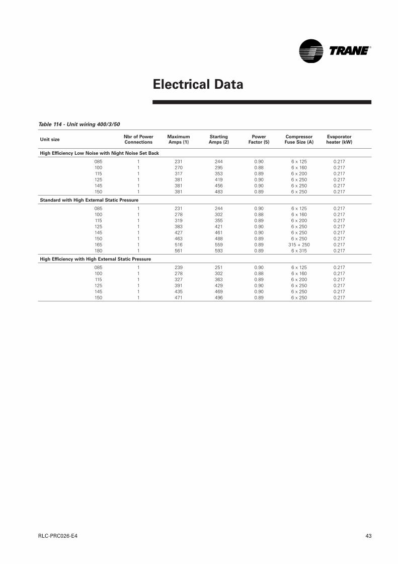
Electrical Data
43RLC-PRC026-E4
Table 114 - Unit wiring 400/3/50
Unit size
High Efficiency Low Noise with Night Noise Set Back
085 1 231 244 0.90 6 x 125 0.217100 1 270 295 0.88 6 x 160 0.217115 1 317 353 0.89 6 x 200 0.217125 1 381 419 0.90 6 x 250 0.217145 1 381 456 0.90 6 x 250 0.217150 1 381 483 0.89 6 x 250 0.217
Standard with High External Static Pressure
085 1 231 244 0.90 6 x 125 0.217100 1 278 302 0.88 6 x 160 0.217115 1 319 355 0.89 6 x 200 0.217125 1 383 421 0.90 6 x 250 0.217145 1 427 461 0.90 6 x 250 0.217150 1 463 488 0.89 6 x 250 0.217165 1 516 559 0.89 315 + 250 0.217180 1 561 593 0.89 6 x 315 0.217
High Efficiency with High External Static Pressure
085 1 239 251 0.90 6 x 125 0.217100 1 278 302 0.88 6 x 160 0.217115 1 327 363 0.89 6 x 200 0.217125 1 391 429 0.90 6 x 250 0.217145 1 435 469 0.90 6 x 250 0.217150 1 471 496 0.89 6 x 250 0.217
Nbr of PowerConnections
MaximumAmps (1)
Starting Amps (2)
Power Factor (5)
CompressorFuse Size (A)
Evaporatorheater (kW)
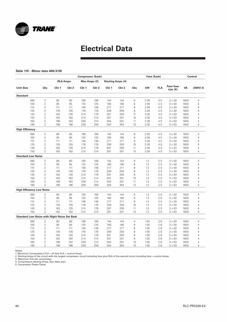
Electrical Data
RLC-PRC026-E444
Table 115 - Motor data 400/3/50
Compressor (Each) Fans (Each) Control
RLA Amps Max Amps (3) Starting Amps (4)
Unit Size Qty Ckt 1 Ckt 2 Ckt 1 Ckt 2 Ckt 1 Ckt 2 Qty kW FLA VA (400V) A
Standard
085 2 80 80 106 106 144 144 6 2.05 4.5 3 x 50 1600 4100 2 95 95 125 125 180 180 6 2.05 4.5 3 x 50 1600 4115 2 111 111 146 146 217 217 6 2.05 4.5 3 x 50 1600 4125 2 135 135 178 178 259 259 6 2.05 4.5 3 x 50 1600 4145 2 162 135 214 178 291 259 9 2.05 4.5 3 x 63 1600 4150 2 162 162 214 214 291 291 10 2.05 4.5 3 x 63 1600 4165 2 196 162 259 214 354 291 11 2.05 4.5 3 x 63 1600 4180 2 196 196 259 259 354 354 12 2.05 4.5 3 x 63 1600 4
High Efficiency
085 2 80 80 106 106 144 144 6 2.05 4.5 3 x 50 1600 4100 2 95 95 125 125 180 180 8 2.05 4.5 3 x 50 1600 4115 2 111 111 146 146 217 217 8 2.05 4.5 3 x 50 1600 4125 2 135 135 178 178 259 259 10 2.05 4.5 3 x 50 1600 4145 2 162 135 214 178 291 259 11 2.05 4.5 3 x 63 1600 4150 2 162 162 214 214 291 291 12 2.05 4.5 3 x 63 1600 4
Standard Low Noise
085 2 80 80 106 106 144 144 6 1.3 2.5 3 x 50 1600 4100 2 95 95 125 125 180 180 6 1.3 2.5 3 x 50 1600 4115 2 111 111 146 146 217 217 6 1.3 2.5 3 x 50 1600 4125 2 135 135 178 178 259 259 6 1.3 2.5 3 x 50 1600 4145 2 162 135 214 178 291 259 9 1.3 2.5 3 x 63 1600 4150 2 162 162 214 214 291 291 10 1.3 2.5 3 x 63 1600 4165 2 196 162 259 214 354 291 11 1.3 2.5 3 x 63 1600 4180 2 196 196 259 259 354 354 12 1.3 2.5 3 x 63 1600 4
High Efficiency Low Noise
085 2 80 80 106 106 144 144 6 1.3 2.5 3 x 50 1600 4100 2 95 95 125 125 180 180 8 1.3 2.5 3 x 50 1600 4115 2 111 111 146 146 217 217 8 1.3 2.5 3 x 50 1600 4125 2 135 135 178 178 259 259 10 1.3 2.5 3 x 50 1600 4145 2 162 135 214 178 291 259 11 1.3 2.5 3 x 63 1600 4150 2 162 162 214 214 291 291 12 1.3 2.5 3 x 63 1600 4
Standard Low Noise with Night Noise Set Back
085 2 80 80 106 106 144 144 4 1.05 2.6 3 x 50 1600 4100 2 95 95 125 125 180 180 6 1.05 2.6 3 x 50 1600 4115 2 111 111 146 146 217 217 6 1.05 2.6 3 x 50 1600 4125 2 135 135 178 178 259 259 6 1.05 2.6 3 x 50 1600 4145 2 162 135 214 178 291 259 8 1.05 2.6 3 x 63 1600 4150 2 162 162 214 214 291 291 8 1.05 2.6 3 x 63 1600 4165 2 196 162 259 214 354 291 10 1.05 2.6 3 x 63 1600 4180 2 196 196 259 259 354 354 10 1.05 2.6 3 x 63 1600 4
Notes: 1. Maximum Compressors FLA + all fans FLA + control Amps 2. Starting Amps of the circuit with the largest compressor circuit including fans plus RLA of the second circuit including fans + control Amps 3. Maximum FLA per compressor. 4. Compressors starting Amps, Star delta start. 5. Compressor Power Factor
Fans fusesize (A)
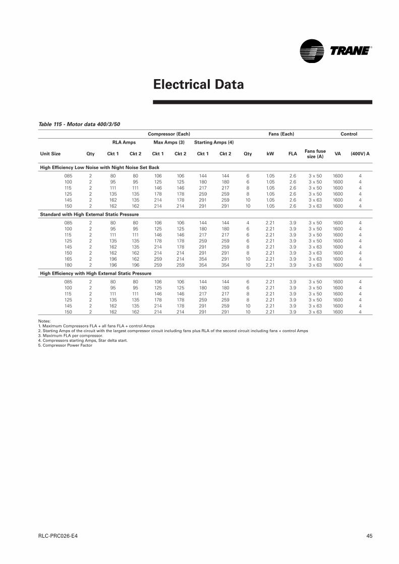
Electrical Data
45RLC-PRC026-E4
Table 115 - Motor data 400/3/50
Compressor (Each) Fans (Each) Control
RLA Amps Max Amps (3) Starting Amps (4)
Unit Size Qty Ckt 1 Ckt 2 Ckt 1 Ckt 2 Ckt 1 Ckt 2 Qty kW FLA VA (400V) A
High Efficiency Low Noise with Night Noise Set Back
085 2 80 80 106 106 144 144 6 1.05 2.6 3 x 50 1600 4100 2 95 95 125 125 180 180 6 1.05 2.6 3 x 50 1600 4115 2 111 111 146 146 217 217 8 1.05 2.6 3 x 50 1600 4125 2 135 135 178 178 259 259 8 1.05 2.6 3 x 50 1600 4145 2 162 135 214 178 291 259 10 1.05 2.6 3 x 63 1600 4150 2 162 162 214 214 291 291 10 1.05 2.6 3 x 63 1600 4
Standard with High External Static Pressure
085 2 80 80 106 106 144 144 4 2.21 3.9 3 x 50 1600 4100 2 95 95 125 125 180 180 6 2.21 3.9 3 x 50 1600 4115 2 111 111 146 146 217 217 6 2.21 3.9 3 x 50 1600 4125 2 135 135 178 178 259 259 6 2.21 3.9 3 x 50 1600 4145 2 162 135 214 178 291 259 8 2.21 3.9 3 x 63 1600 4150 2 162 162 214 214 291 291 8 2.21 3.9 3 x 63 1600 4165 2 196 162 259 214 354 291 10 2.21 3.9 3 x 63 1600 4180 2 196 196 259 259 354 354 10 2.21 3.9 3 x 63 1600 4
High Efficiency with High External Static Pressure
085 2 80 80 106 106 144 144 6 2.21 3.9 3 x 50 1600 4100 2 95 95 125 125 180 180 6 2.21 3.9 3 x 50 1600 4115 2 111 111 146 146 217 217 8 2.21 3.9 3 x 50 1600 4125 2 135 135 178 178 259 259 8 2.21 3.9 3 x 50 1600 4145 2 162 135 214 178 291 259 10 2.21 3.9 3 x 63 1600 4150 2 162 162 214 214 291 291 10 2.21 3.9 3 x 63 1600 4
Notes: 1. Maximum Compressors FLA + all fans FLA + control Amps 2. Starting Amps of the circuit with the largest compressor circuit including fans plus RLA of the second circuit including fans + control Amps 3. Maximum FLA per compressor. 4. Compressors starting Amps, Star delta start. 5. Compressor Power Factor
Fans fusesize (A)

Mechanical Specifications
RLC-PRC026-E446
General
Units are leak and pressure testedat 35 bar high side, 19 bar low side,then evacuated and charged.Packaged units ship with a fulloperating charge of oil andrefrigerant.
Unit panels, structural elements andcontrol boxes are constructed ofgalvanized steel and mounted on awelded structural steel base. Unitpanels and control boxes arefinished with powder paintRAL 9002.
Evaporator
The evaporator is a tube-in-shellheat exchanger design withinternally finned copper tubes rollerexpanded into the tube sheet. Theevaporator is designed, tested andstamped in accordance with theappropriate pressure vessel codeapproval for a refrigerant sideworking pressure of 32 bar. Theevaporator is designed for awaterside working pressure of16 bar. Water connections areVictaulic. The evaporator has onewater pass with a series of internalbaffles. Each shell includes a vent, adrain and fittings for temperaturecontrol sensors and is insulatedwith 3 /4 -inch Armaflex II or equalinsulation (K=0.26). Heat tape isprovided to protect the evaporatorfrom freezing at ambienttemperatures down to -18°C.
Condenser and Fans
Air-cooled condenser coils havealuminum fins mechanically bondedto internally finned seamless coppertubing. The condenser coil has anintegral subcooling circuit.Condensers are factory leak testedat 35 bar. Direct-drive verticaldischarge air foil ZephyrWingcondenser fans are dynamicallybalanced. Three-phase condenserfans motors with permanentlylubricated ball bearing are provided.Standard units will start andoperate between of 4°C (39 F) to themaximum possible ambient of theselected unit.
Heat Recovery Exchanger
The Heat Recovery Exchanger is abrazed plate exchanger (one forTotal Heat Recovery (THR) units andtwo for Partial Heat Recovery (PHR)units), connected to the compressordischarge line, and sized to recoverup to 80% of the nominal coolingcapacity for THR units and 25% ofthe nominal cooling capacity forPHR units.
The Heat Recovery Exchanger is notapproved for Food and Beverageapplications. The use of a primaryloop is mandatory.
Note:
• THR and PHR exchangers arefreeze protected through aresistance.
Compressor and Lube Oil
System
The rotary screw compressor issemi-hermetic, direct drive,3000 rpm, with capacity controlslide valve, a load/unload valve,rolling element bearings, differentialrefrigerant pressure oil pump, oilfilter and oil heater. The motor is asuction gas-cooled, hermeticallysealed, two-pole squirrel cageinduction motor. Oil separatordevices are provided separate fromthe compressor. Check valves in thecompressor discharge and lube oilsystem are provided.
Refrigeration Circuits
Each unit has two refrigerantcircuits, with one rotary screwcompressor per circuit. Eachrefrigerant circuit includes a liquidline shutoff valve, removable corefilter drier, charging port and anelectronic expansion valve. Fullymodulating compressors andelectronic expansion valves providevariable capacity modulation overthe entire operating range.

Mechanical Specifications
47RLC-PRC026-E4
Unit Controls
All unit controls are housed in aweather-tight enclosure with hingeddoors to allow for customerconnection of power wiring andremote interlocks. All controls,including sensors, are factorymounted and tested prior toshipment. All cataloged unitscomply with EN 60204 and are EMCcompatible.
Microcomputer controls provide allcontrol functions including start-upand shut down, leaving chilledwater temperature control,compressor and electronicexpansion valve modulation, fansequencing, anti-recycle logic,automatic lead/lag compressorstarting and load limiting.
The unit control module, utilizingAdaptive Control™ microprocessor,automatically takes action to avoidunit shutdown due to abnormaloperating conditions associatedwith low refrigerant temperature,high condensing temperature andmotor current overload. Should theabnormal operating conditioncontinue until a protective limit isviolated, the unit will be shut down.Unit protective functions includeloss of chilled water flow,evaporator freezing, loss ofrefrigerant, low refrigerant pressure,high refrigerant pressure, reverserotation, compressor starting andrunning over current, phase loss,phase imbalance, phase reversal,and loss of oil flow.
A menu driven digital displayindicates over 60 operating datapoints including chilled watersetpoint, current limit setpoint,leaving chilled water temperature,evaporator and condenserrefrigerant pressures andtemperatures. Over 60 diagnosticchecks are made and displayedwhen a problem is detected. Thedigital display can be read andadvanced on the unit withoutopening any control panel doors.
Standard power connectionsinclude main three phase power.
Specificity of Total Heat
Recovery units
An additional control module ispresent on Heat Recovery units. Itsrole is to control the fans tomaintain the saturated condensingtemperature based on the hot watersetpoint and also a 3-way valve thatallows to partially bypass thecondenser when inlet watertemperature is low, thus ensuringthe correct operation of the unit.
Note: the use of a 3-way valve canbe avoided by using a variablespeed pump. The additional controlmodule can provide a 2-10V signalto control it. This solution allowsbetter control of the outlet watertemperature and limits powerconsumption of the pump.
Starters
Starters are housed in aweathertight enclosure withremovable cover plate to allow forcustomer connection of powerwiring. Wye Delta closed transitionstarters are standard on all RTADunits.

Literature Order Number RLC-PRC026-E4
Date 1205
New
Literature Stocking Location Europe
Trane has a policy of continuous product and product data improvement and reserves the right tochange design and specifications without notice.
www.trane.com
For more information, contact your local sales office or e-mail us at [email protected]
American Standard Europe BVBARegistered Office: 1789 Chaussée de Wavre, 1160 Brussels - Belgium